96
2001 Microchip Technology Inc. DS51028D PICSTART ® PLUS USER’S GUIDE M
2001 Microchip Technology Inc. DS51028D
PICSTART® PLUSUSER’S GUIDE
M

“All rights reserved. Copyright © 2001, Microchip TechnologyIncorporated, USA. Information contained in this publicationregarding device applications and the like is intended throughsuggestion only and may be superseded by updates. No rep-resentation or warranty is given and no liability is assumed byMicrochip Technology Incorporated with respect to the accu-racy or use of such information, or infringement of patents orother intellectual property rights arising from such use or oth-erwise. Use of Microchip’s products as critical components inlife support systems is not authorized except with expresswritten approval by Microchip. No licenses are conveyed,implicitly or otherwise, under any intellectual property rights.The Microchip logo and name are registered trademarks ofMicrochip Technology Inc. in the U.S.A. and other countries.All rights reserved. All other trademarks mentioned herein arethe property of their respective companies. No licenses areconveyed, implicitly or otherwise, under any intellectual prop-erty rights.”
DS51028D
Trademarks
The Microchip name, logo, PIC, PICmicro, PICMASTER, PIC-START, PRO MATE, KEELOQ, SEEVAL, MPLAB and TheEmbedded Control Solutions Company are registered trade-marks of Microchip Technology Incorporated in the U.S.A. andother countries.
Total Endurance, In-Circuit Serial Programming (ICSP), Filter-Lab, FlexROM, fuzzyLAB, ICEPIC, microID, MPASM, MPLIB,MPLINK, MXDEV, PICDEM and Migratable Memory aretrademarks of Microchip Technology Incorporated in theU.S.A.
Serialized Quick Term Programming (SQTP) is a service markof Microchip Technology Incorporated in the U.S.A.
All other trademarks mentioned herein are property of theirrespective companies.
© 2001, Microchip Technology Incorporated, Printed in theU.S.A., All Rights Reserved.
2001 Microchip Technology Inc.
Microchip received QS-9000 quality system certification for its worldwide headquarters, design and wafer fabrication facilities in Chandler and Tempe, Arizona in July 1999. The Company’s quality system processes and procedures are QS-9000 compliant for its PICmicro® 8-bit MCUs, KEELOQ® code hopping devices, Serial EEPROMs and microperipheral products. In addition, Microchip’s quality system for the design and manufacture of development systems is ISO 9001 certified.

12 PICSTART® PLUS USER’S GUIDE
Table of Contents
General InformationIntroduction ................................................................................................ 1
Highlights ................................................................................................... 1
About This Guide ....................................................................................... 1
Warranty Registration ................................................................................ 3
Recommended Reading ............................................................................ 3
Troubleshooting ......................................................................................... 4
The Microchip Internet Web Site ............................................................... 5
Development Systems Customer Notification Service .............................. 6
Customer Support ..................................................................................... 8
Chapter 1. Quick Start1.1 Introduction ..................................................................................... 9
1.2 Highlights ........................................................................................ 9
1.3 Installing MPLAB IDE and PICSTART Plus .................................... 9
1.4 Connecting PICSTART Plus to Your PC ...................................... 10
1.5 Using PICSTART Plus with MPLAB IDE ...................................... 10
Chapter 2. PICSTART Plus Preview
2.1 Introduction ................................................................................... 13
2.2 Highlights ...................................................................................... 13
2.3 What is PICSTART Plus ............................................................... 13
2.4 Components of PICSTART Plus System ...................................... 14
2.5 PICSTART Plus CE Compliance .................................................. 14
2.6 How PICSTART Plus Helps You .................................................. 15
2.7 MPLAB Integrated Development Environment ............................. 15
2.8 MPLAB Development Tools .......................................................... 16
2001 Microchip Technology Inc. DS51028D-page i
PICSTART® Plus User’s Guide
Chapter 3. PICSTART Plus Installation3.1 Introduction ...................................................................................17
3.2 Highlights ......................................................................................17
3.3 Host Computer System Requirements ..........................................17
3.4 Installing PICSTART Plus Hardware .............................................17
3.5 Installing MPLAB IDE Software .....................................................19
3.6 Starting MPLAB IDE .....................................................................20
3.7 Configuring the Serial Port for PICSTART Plus ............................21
3.8 Setting Up the MPLAB Development Mode ..................................22
3.9 Starting PICSTART Plus ...............................................................23
Chapter 4. Programming Examples4.1 Introduction ...................................................................................25
4.2 Example: Programming a Mid-Range PICmicro MCU Device ......25
4.3 Example: Programming Calibration Devices .................................34
Chapter 5. Using PICSTART Plus5.1 Introduction ...................................................................................49
5.2 Highlights ......................................................................................49
5.3 Procedure for Programming a Device ...........................................49
5.4 Verifying the Programming ............................................................57
5.5 Reading a Device ..........................................................................58
Chapter 6. PICSTART Plus – Reference
6.1 Introduction ...................................................................................61
6.2 Highlights ......................................................................................61
6.3 PICSTART Plus Device Programmer Dialog ................................62
6.4 Configuration Bits Dialog ...............................................................64
6.5 Program Memory Window .............................................................65
6.6 Program/Verify Dialog ...................................................................66
6.7 Read Device Dialog ......................................................................67
6.8 PICSTART Plus Menu Items .........................................................68
6.9 Upgrading the PICSTART Plus Operating System .......................69
DS51028D-page ii 2001 Microchip Technology Inc.

Table of Contents
Appendix A. Connecting to a 25-Pin Serial PortA.1 Introduction ................................................................................... 71
A.2 Highlights ...................................................................................... 71
A.3 Connection Description ................................................................. 71
Appendix B. PICSTART Plus VPP AdjustmentB.1 Introduction ................................................................................... 73
B.2 Highlights ...................................................................................... 73
B.3 Overview ....................................................................................... 73
B.4 Procedure ..................................................................................... 73
B.5 Validation ...................................................................................... 73
Appendix C. Troubleshooting
C.1 Introduction ................................................................................... 75
C.2 Highlights ...................................................................................... 75
C.3 Common Problems ....................................................................... 75
Index ......................................................................................................... 81
Worldwide Sales and Service ................................................................. 90
2001 Microchip Technology Inc. DS51028D-page iii

PICSTART® Plus User’s Guide
NOTES:
DS51028D-page iv 2001 Microchip Technology Inc.

®
PICSTART PLUS USER’S GUIDE12General InformationIntroductionThis chapter contains general information about this manual and contacting customer support.
HighlightsTopics covered in this chapter:
• About this Guide
• Recommended Reading
• Warranty Registration
• Troubleshooting
• The Microchip Internet Web Site
• Development Systems Customer Notification Service
• Customer Support
About This Guide
Document LayoutThis document describes how to use PICSTART Plus as a development tool to program firmware in a PICmicro device. The manual layout is as follows:
• Chapter 1: PICSTART Plus Preview – What PICSTART Plus is and how it works.
• Chapter 2: Installing and Setting Up PICSTART Plus – Describes how to install PICSTART Plus hardware and the MPLAB® IDE software. Explains how to set up the MPLAB IDE and PICSTART Plus to work together and how to start PICSTART Plus from the MPLAB IDE.
• Chapter 3: Programming Examples – Contains several examples (tutorials) for programming calibration memory devices, memory devices, and other PICmicro® MCU devices.
• Chapter 4: Using PICSTART Plus with MPLAB – Provides step-by-step instructions on using PICSTART Plus to program, read, and verify devices.
• Chapter 5: PICSTART Plus – MPLAB Reference – Describes PICSTART Plus dialogs and menu options.
• Appendix A: Connecting to a 25-Pin Serial Port – Describes how to connect PICSTART Plus to a 25-pin serial port.
2001 Microchip Technology Inc. DS51028D-page 1

PICSTART® Plus User’s Guide
• Appendix B: PICSTART Plus VPP Adjustment – Describes how to change the VPP programming voltage of older PICSTART Plus hard-ware units to comply with revised programming specifications.
• Appendix C: Troubleshooting – Provides information on solving com-mon problems.
• Index – Provides a cross-reference listing of terms, features, and sec-tions of this document.
• Worldwide Sales and Service – Lists Microchip sales and service locations and telephone numbers worldwide.
Conventions Used in this GuideThis manual uses the following documentation conventions:
Documentation Conventions
Description Represents Examples
Code (Courier font):
Plain characters Sample codeFilenames and paths
#define STARTc:\autoexec.bat
Angle brackets: < >
Variables <label>, <exp>
Square brackets [ ] Optional arguments MPASMWIN [main.asm]
Curly brackets and pipe character: { | }
Choice of mutually exclusive argumentsAn OR selection
errorlevel {0|1}
Lower case charac-ters in quotes
Type of data “filename”
Ellipses... Used to imply (but not show) additional text that is not rele-vant to the example
list [“list_option..., “list_option”]
0xnnn A hexadecimal number where n is a hexadecimal digit
0xFFFF, 0x007A
Italic characters A variable argument; it can be either a type of data (in lower case characters) or a specific example (in uppercase characters)
char isascii (char, ch);
Interface (Helvetica font):
Underlined, italic text with right arrow
A menu selection from the menu bar
File > Save
Bold characters A window or dialog button to click
OK, Cancel
Characters in angle brackets < >
A key on the keyboard <Tab>, <Ctrl-C>
DS51028D-page 2 2001 Microchip Technology Inc.
General Information
UpdatesAll documentation becomes dated, and this user’s guide is no exception. Since the MPLAB IDE, PICSTART Plus and other Microchip tools are constantly evolving to meet customer needs, some MPLAB dialogs and/or tool descriptions may differ from those in this document. Please refer to our web site at http://www.microchip.com to obtain the latest documentation available.
Warranty RegistrationPlease complete the enclosed Warranty Registration Card and mail it promptly. Sending in your Warranty Registration Card entitles you to receive new product updates. Interim software releases are available at the Microchip web site.
Recommended ReadingThis user’s guide describes how to use PICSTART Plus. The data sheets contain current information on programming the specific microcontroller devices.
README.PLS
For the latest information on using PICSTART Plus, read the README.PLS file (ASCII text file) included with the PICSTART Plus software. The README.PLS file contains update information that may not be included in this document.
MPLAB IDE User’s Guide (DS51025)
Comprehensive guide that describes installation and features of Microchip’s MPLAB Integrated Development Environment (IDE), as well as the editor and simulator functions in the MPLAB environment.
MPASM™ User’s Guide with MPLINK™ & MPLIB™ (DS33014)
Describes how to use Microchip Universal PICmicro Microcontroller Assembler (MPASM), Linker (MPLINK), and Librarian (MPLIB).
Documents (Helvetica font):
Italic characters Referenced books MPLAB IDE User’s Guide
Documentation Conventions (Continued)
Description Represents Examples
2001 Microchip Technology Inc. DS51028D-page 3

PICSTART® Plus User’s Guide
Technical Library CD-ROM (DS00161)
This CD-ROM contains comprehensive data sheets for Microchip PICmicro® MCU devices available at the time of print. To obtain this disk, contact the nearest Microchip Sales and Service location (see back page) or download individual data sheet files from the Microchip web site (http://www.microchip.com).
Embedded Control Handbook (DS00711)
This handbook consists of several documents that contain a wealth of information about microcontroller applications. To obtain these documents, contact the nearest Microchip Sales and Service location (see back page).
The application notes described in these manuals are also obtainable from Microchip Sales and Service locations or from the Microchip web site (http://www.microchip.com).
PICmicro Mid-Range MCU Family Reference Manual (DS33023)
This manual explains the general details and operation of the MCU family architecture and peripheral modules. It is designed to complement the device data sheets.
Microsoft® Windows® Manuals
This manual assumes that users are familiar with Microsoft Windows operating system. Many excellent references exist for this software program, and should be consulted for general operation of Windows.
TroubleshootingSee Appendix C for information on common problems.
DS51028D-page 4 2001 Microchip Technology Inc.

General Information
The Microchip Internet Web SiteMicrochip provides online support on the Microchip World Wide Web (WWW)site.
The web site is used by Microchip as a means to make files and informationeasily available to customers. To view the site, the user must have access tothe Internet and a web browser, such as Netscape® Communicator orMicrosoft® Internet Explorer®. Files are also available for FTP download fromour FTP site.
Connecting to the Microchip Internet Website
The Microchip web site is available by using your favorite Internet browserto attach to:
http://www.microchip.com
The file transfer site is available by using an FTP program/client to connect to:
ftp://ftp.microchip.com
The web site and file transfer site provide a variety of services. Users maydownload files for the latest Development Tools, Data Sheets, ApplicationNotes, User’s Guides, Articles, and Sample Programs. A variety of Microchipspecific business information is also available, including listings of Microchipsales offices, distributors and factory representatives. Other data available forconsideration is:
• Latest Microchip Press Releases• Technical Support Section with Frequently Asked Questions • Design Tips• Device Errata• Job Postings• Microchip Consultant Program Member Listing• Links to other useful web sites related to Microchip Products• Conferences for products, Development Systems, technical information
and more• Listing of seminars and events
2001 Microchip Technology Inc. DS51028D-page 5
PICSTART® Plus User’s Guide
Development Systems Customer Notification ServiceMicrochip started the customer notification service to help our customers keep current on Microchip products with the least amount of effort. Once you subscribe to one of our list servers, you will receive email notification whenever we change, update, revise or have errata related to that product family or development tool. See the Microchip web page at http://www.microchip.com for other Microchip list servers.
The Development Systems list names are:
• Compilers
• Emulators
• Programmers
• MPLAB
• Otools (other tools)
Once you have determined the names of the lists that you are interested in, you can subscribe by sending a message to:
with the following as the body:
subscribe <listname> yourname
Here is an example:
subscribe programmers John Doe
To UNSUBSCRIBE from these lists, send a message to:
with the following as the body:
unsubscribe <listname> yourname
Here is an example:
unsubscribe programmers John Doe
The following sections provide descriptions of the available Development Systems lists.
CompilersThe latest information on Microchip C compilers, Linkers and Assemblers. These include MPLAB C17, MPLAB C18, MPLINK, MPASM as well as the Librarian, MPLIB for MPLINK.
To SUBSCRIBE to this list, send a message to:
with the following as the body:
subscribe compilers yourname
DS51028D-page 6 2001 Microchip Technology Inc.
General Information
EmulatorsThe latest information on Microchip In-Circuit Emulators. These include MPLAB ICE and PICMASTER.
To SUBSCRIBE to this list, send a message to:
with the following as the body:
subscribe emulators yourname
ProgrammersThe latest information on Microchip PICmicro device programmers. These include PRO MATE II and PICSTART Plus.
To SUBSCRIBE to this list, send a message to:
with the following as the body:
subscribe programmers yourname
MPLABThe latest information on Microchip MPLAB, the Windows Integrated Development Environment for development systems tools. This list is focused on MPLAB, MPLAB SIM, MPLAB’s Project Manager and general editing and debugging features. For specific information on MPLAB compilers, linkers and assemblers, subscribe to the COMPILERS list. For specific information on MPLAB emulators, subscribe to the EMULATORS list. For specific information on MPLAB device programmers, please subscribe to the PROGRAMMERS list.
To SUBSCRIBE to this list, send a message to:
with the following as the body:
subscribe mplab yourname
OtoolsThe latest information on other development system tools provided by Microchip. For specific information on MPLAB and its integrated tools refer to the other mail lists.
To SUBSCRIBE to this list, send a message to:
with the following as the body:
subscribe otools yourname
2001 Microchip Technology Inc. DS51028D-page 7

PICSTART® Plus User’s Guide
Customer SupportUsers of Microchip products can receive assistance through several channels:
• Distributor or Representative
• Local Sales Office
• Field Application Engineer (FAE)
• Corporate Applications Engineer (CAE)
• Hotline
Customers should call their distributor, representative, or field application engineer (FAE) for support. Local sales offices are also available to help customers. See the back cover for a listing of sales offices and locations.
Corporate applications engineers (CAEs) may be contacted at (480) 792-7627.
In addition, there is a Systems Information and Upgrade Line. This line provides system users a listing of the latest versions of all of Microchip's development systems software products. Plus, this line provides information on how customers can receive any currently available upgrade kits.
The Hotline Numbers are:
1-800-755-2345 for U.S. and most of Canada, and
1-480-792-7302 for the rest of the world.
DS51028D-page 8 2001 Microchip Technology Inc.

®
PICSTART PLUS USER’S GUIDE12Chapter 1. Quick Start1.1 IntroductionThis chapter provides the limited information that experienced users of PCs and embedded application development tools need in order to quickly start using PICSTART Plus.
1.2 HighlightsTopics covered in this chapter:
• Installing MPLAB® IDE and PICSTART Plus
• Connecting the PICSTART Plus to your PC
• Using PICSTART Plus with MPLAB IDE
- Enabling (starting) PICSTART Plus- Setting up the Device Programmer and Configuration Bits- Loading a HEX File- Checking for a Blank Device- Programming, Verifying, and Reading a Device
1.3 Installing MPLAB IDE and PICSTART Plus1. PICSTART Plus is a component of the MPLAB Integrated Development
Environment (IDE). To install the MPLAB IDE software, insert theMPLAB IDE installation CD and run MPXXXX.EXE, where XXXX repre-sents the version of the MPLAB IDE software. This executable is in theroot directory of the CD.
2. When the component selection window of the installation programappears, make sure PICSTART Plus is checkmarked in the list of com-ponents to install. As a minimum, install the MPLAB IDE software andMPASM/MPLINK. You should also install the MPLAB SIM and help files.Continue with the installation by following the instructions displayed bythe installation program. Under Language Components, select All.
If you previously installed the MPLAB IDE software but did not install PICSTART Plus, you must repeat the installation. You can clear all the checkmarks except PICSTART Plus.
2001 Microchip Technology Inc. DS51028D-page 9

PICSTART® Plus User’s Guide
1.4 Connecting PICSTART Plus to Your PCFollow these steps to connect the PICSTART Plus to your PC.
1. Use the RS-232 communications cable to connect the PICSTART Plusto an available COM port on your PC.
2. Install the power supply.
You are now ready to start using PICSTART Plus with the MPLAB IDE.
1.5 Using PICSTART Plus with MPLAB IDE
1.5.1 Starting PICSTART Plus1. Start the MPLAB IDE by double-clicking the MPLAB desktop icon or by
selecting Programs > Microchip MPLAB > MPLAB from your Start menu. 2. Select Options > Programmer Options > Communications Port Setup
from the MPLAB menu. Select the COM port that the PICSTART Plus ison.
3. If the PICSTART Plus menu item is not on the MPLAB menu, you mustselect the PICSTART Plus programmer. In the MPLAB desktop, selectOptions > Programmer Options > Select Programmer. Select PICSTARTPlus Device Programmer and click OK. A message will prompt you torestart the MPLAB software in order for the change to take effect. ClickYes. The MPLAB IDE will shut down, and the PICSTART Plus menu willappear on the MPLAB menu when you restart the MPLAB IDE software.
4. Select Options > Development Mode. Select the MPLAB SIM or EditorOnly development mode and select the device you are going to program.Click OK.
5. Select PICSTART Plus > Enable Programmer from the MPLAB menu.The MPLAB IDE will attempt to establish communications with thePICSTART Plus, and the Program Memory window, as well as thePICSTART Plus Device Programmer and Configuration Bits dialogs willappear.
WARNING
DO NOT connect power with a device in the socket. Damage to the device may result.
DS51028D-page 10 2001 Microchip Technology Inc.
Quick Start
1.5.2 Setting up the Device Programmer and Configuration BitsThe PICSTART Plus Device Programmer dialog is open whenever the programmer is enabled. Closing this dialog disables the programmer.
1. Make sure the correct device is displayed. If the device you want to pro-gram is not listed, you may need to upgrade your PICSTART Plus oper-ating system (see Section 6.9). You may only need to upgrade to thelatest version of the MPLAB IDE software.
2. If you want to identify the programming on a device (e.g., version con-trol), click Device ID and edit the device ID or select unprotected check-sum. Click OK.
3. Set the configuration bits in the Configuration Bits dialog. If you set con-figuration bits in your source code, this dialog will be updated with thosevalues when you rebuild your project. The values in this dialog will beprogrammed into the device you program.
If the Configuration Bits dialog is not visible, click Configuration Bits inthe PICSTART Plus Device Programmer dialog to reopen it.
1.5.3 Loading a Hex FileIf you have a hex file ready for programming into a device, select File > Import > Import to Memory to load the hex code into the MPLAB Program Memory window. Select Window > Program Memory to view the contents of program memory.
1.5.4 Checking for a Blank DeviceInsert the device to be programmed into the PICSTART Plus socket.
Click Blank in the PICSTART Plus Device Programmer dialog to verify that the device is blank (all bits set to ‘1’).
If you are programming a one-time programmable (OTP) device, use the Configuration Bits dialog to set the configuration bits to their factory settings. Select PICSTART Plus > Blank Check OTP to make sure that all program memory bits are set to ‘1’ and that the configuration bits match the value in the Configuration Bits dialog.
2001 Microchip Technology Inc. DS51028D-page 11
PICSTART® Plus User’s Guide
1.5.5 Programming, Verifying, and Reading a DeviceIf you have followed the previous sections, you are ready to program a device. To program the entire device, click Program in the PICSTART Plus Device Programmer dialog.
To program selectively (part of program memory or configuration bits) select PICSTART Plus > Program/Verify. Select the memory range and items to be programmed, and click Program in the Program/Verify dialog.
When programming has completed, “Success” or “Failure” will appear to the right of the Start Address. An error window displaying the expected and actual data will appear if programming failed.
Note: If you are programming a windowed calibration device, be sure tostore its calibration data as described in Section 4.3.3.4, to ensureproper operation of the device.
DS51028D-page 12 2001 Microchip Technology Inc.

®
PICSTART PLUS USER’S GUIDE12Chapter 2. PICSTART Plus Preview2.1 Introduction This chapter will present an overview of the PICSTART Plus development programmer. The features and requirements of PICSTART Plus are presented.
2.2 HighlightsTopics covered in this chapter:
• What is PICSTART Plus
• Components of PICSTART Plus System
• PICSTART Plus CE Compliance
• How PICSTART Plus Helps You
• MPLAB Integrated Development Environment
• MPLAB Development Tools
2.3 What is PICSTART PlusThe PICSTART Plus is a Microchip microcontroller development programmer that enables you to program user software into PICmicro microcontroller (MCU) devices (DIP packages only—adapters available for PIC16C9XX and PIC17C7XX devices).
Note: The PICSTART Plus development system is designed for use in firmware development and is not intended for production use.
2001 Microchip Technology Inc. DS51028D-page 13

PICSTART® Plus User’s Guide
2.4 Components of PICSTART Plus SystemThe PICSTART Plus device programmer system consists of the following:
1. PICSTART Plus device programmer2. RS-232 Interface cable to connect to any standard PC serial port3. MPLAB IDE software, an Integrated Development Environment includ-
ing a text editor, project manager, MPASM assembler, and MPLAB SIMsimulator
4. Blank chips for programming5. 9V power supply (not shown)
Figure 2.1: PICSTART Plus System
2.5 PICSTART Plus CE ComplianceThe PICSTART Plus development system is designed, tested, and certified to meet the Electromagnetic Compatibility requirements known as the CE compliance directives. These standards set by the European Union (EU) countries include limiting radiated emission, reducing susceptibility to radiated emission, and reducing susceptibility to Electrostatic Discharge (ESD).
1
2
3
4
DS51028D-page 14 2001 Microchip Technology Inc.
PICSTART Plus Preview
2.6 How PICSTART Plus Helps YouPICSTART Plus device programmer system has the following features:
• Programs PICmicro MCUs, including program memory, configuration bits, and ID locations.
• Communicates with the PC via a standard RS-232 cable.
• Operates as a Microsoft® Windows® application on a PC-compatible host system within the MPLAB Integrated Development Environment.
• With the MPLAB IDE, you can create, display, and edit files to be pro-grammed into PICmicro MCUs.
In addition, you can verify that the PICmicro MCUs are blank and verify that the code in the target microcontroller matches your firmware. You can also read code from an unprotected PICmicro MCU into the MPLAB IDE’s program memory window for debugging and programming into other PICmicro devices.
2.7 MPLAB Integrated Development Environment The MPLAB IDE desktop provides an integrated development environment (IDE) for developing and debugging your application. PICSTART Plus is integrated into the MPLAB IDE.
This document covers the basic setup and operation of the PICSTART Plus device programmer, but it does not cover all functions of the MPLAB IDE. Read the MPLAB IDE User’s Guide (DS51025) to get a full understanding of the features and debugging capabilities of the MPLAB IDE.
2001 Microchip Technology Inc. DS51028D-page 15

PICSTART® Plus User’s Guide
2.8 MPLAB Development ToolsThe MPLAB IDE integrates several tools to provide a complete development environment.
• MPLAB Project Manager
Use the Project Manager to create a project and work with the specificfiles related to the project. When using a project, you can rebuild sourcecode and download it to the simulator or emulator with a single mouseclick.
• MPLAB Editor
Use the MPLAB Editor to create and edit text files such as source files,code, and linker script files.
• MPLAB SIM Simulator
The software simulator models the instruction execution and I/O of thePICmicro MCUs.
• MPLAB ICE Emulator
The MPLAB ICE emulator uses hardware to emulate PICmicro MCUs inreal time, either with or without a target system.
• MPASM Assembler/MPLINK Linker/MPLIB Librarian
The MPASM assembler allows source code to be assembled withoutleaving MPLAB. MPLINK creates the final application by linking relocat-able modules from MPASM, MPLAB C17, and MPLAB C18. MPLIBmanages custom libraries for maximum code reuse.
• MPLAB CXX C Compilers
The MPLAB C17 and MPLAB C18 C Compilers provide ANSI-basedhigh level source code solutions. Complex projects can use a combina-tion of C and assembly source files to obtain the maximum benefits ofspeed and maintainability.
• PRO MATE® II and PICSTART Plus Programmers
Develop code with the simulator or an emulator, assemble or compile it,and then use one of these tools to program devices. This can all beaccomplished with the MPLAB IDE. Although PRO MATE II does notrequire the MPLAB IDE to operate, programming is easier using theMPLAB IDE.
• Third Party Tools
Many other companies have development tools for Microchip productsthat work with the MPLAB IDE. Consult the Microchip Third Party Guide(DS00104).
DS51028D-page 16 2001 Microchip Technology Inc.

®
PICSTART PLUS USER’S GUIDE12Chapter 3. PICSTART Plus Installation3.1 IntroductionThe PICSTART Plus development system requires connecting the hardware to the PC as well as the installation of the MPLAB IDE software. This chapter covers the details of both hardware and software installation.
3.2 HighlightsTopics covered in this chapter:
• Host Computer System Requirements
• Installing PICSTART Plus Hardware
• Installing MPLAB IDE Software
• Starting MPLAB IDE
• Configuring the Serial Port for PICSTART Plus
• Setting Up the MPLAB IDE Development Mode
• Starting PICSTART Plus
3.3 Host Computer System RequirementsThe following minimum configuration is required to run the MPLAB IDE:
• Pentium® class PC• Microsoft Windows 3.x, Windows 95/98, Windows NT®, or
Windows 2000®
• 16 MB memory (32 MB recommended)• 45 MB of hard disk space• One serial port
3.4 Installing PICSTART Plus HardwareThe PICSTART Plus hardware is simple to set up. First, the communications cable is attached, and then the power supply is connected.
3.4.1 Installing the CablePICSTART Plus provides communications with the host PC via an RS-232 9-pin, D type connector. PICSTART Plus is Data Communication Equipment (DCE), and hardware handshaking is via Clear-To-Send (CTS) and Request-To-Send (RTS).
2001 Microchip Technology Inc. DS51028D-page 17
PICSTART® Plus User’s Guide
A 6-foot data cable with DB-9 connectors is supplied with PICSTART Plus. All lines on the data cable are wired straight through. This cable is NOT a null modem cable.
• Connect one end of the cable to an available COM port on your PC. Check your PC set up to see which communications port is available. Usually a mouse device is connected to COM1 or COM2. If you have a modem, you might not have a third serial port on your PC.
• Connect the cable from your COM port to the PICSTART Plus develop-ment programmer.
3.4.2 Installing the Power SupplyThe PICSTART Plus comes with a 9V input power supply.
PICSTART Plus requires +9 volts ±10% at 500 mA (max.) on the center positive 2.5 mm terminal.
• Plug the power supply into a power socket and connect the power sup-ply cable to the PICSTART Plus.
WARNING
DO NOT connect power with a device in the socket. Damage to the device may result.
DS51028D-page 18 2001 Microchip Technology Inc.

PICSTART Plus Installation
3.5 Installing MPLAB IDE SoftwareInstall the MPLAB IDE software by following the instructions in the MPLAB IDE User’s Guide (DS51025). A brief summary of this procedure, as well as how to obtain and install the PICSTART Plus upgrades, is discussed in the next sections.
3.5.1 Installation SummaryRefer to the MPLAB IDE User’s Guide for more detailed instructions.
• Insert the MPLAB IDE CD-ROM into your CD-ROM drive(Example: drive D).
• Run the Setup program.
- For Windows 3.x/NT 3.51: From the Program Manager Run option, type D:\setup.exe.
- For Windows 95/98, Windows NT 4.0, or Windows 2000: From the Start menu, select Run. In the Run dialog, type D:\setup.exe (assuming that D is your computer’s CD-ROM drive).
• Follow the on-screen instructions to install the MPLAB IDE. Be sure the checkbox to install PICSTART Plus is checked (Figure 3.1).
Figure 3.1: Select Components Dialog
2001 Microchip Technology Inc. DS51028D-page 19

PICSTART® Plus User’s Guide
3.6 Starting MPLAB IDE Once the MPLAB IDE is installed on your PC, you run it by one of the following methods:
• For Windows 3.x/NT 3.51: Double-click on the MPLAB icon.
• For Windows 95/98, Windows NT 4.0, or Windows 2000: From the Start menu, select Programs > Microchip MPLAB > MPLAB.
The MPLAB desktop should look like Figure 3.2.
Figure 3.2: MPLAB Desktop
DS51028D-page 20 2001 Microchip Technology Inc.

PICSTART Plus Installation
3.7 Configuring the Serial Port for PICSTART PlusFrom the MPLAB IDE, select Options > Programmer Options > Communications Port Setup. A dialog similar to the one shown in Figure 3.3 will appear.
Figure 3.3: Communications Port Setup Dialog
The Communications Port Setup Dialog shows the possible PC serial communication ports. Select the COM port to which you connected the PICSTART Plus, and click OK. The MPLAB IDE will attempt to contact PICSTART Plus to verify the port. Click Cancel if you want to close the dialog without selecting a COM port.
If PICSTART Plus is not found on the selected COM port, the dialog shown in Figure 3.4 appears.
Figure 3.4: Communications Error Dialog
Clicking No will retain the new COM port setting without trying to contact PICSTART Plus again. Clicking Yes will cause the MPLAB IDE to try again to contact PICSTART Plus on the specified COM port.
If you cannot establish communications between the PC and PICSTART Plus, make sure you have installed the hardware and software correctly (see Chapter 3). If you still cannot establish communications between the PC and PICSTART Plus, please see Appendix C.
2001 Microchip Technology Inc. DS51028D-page 21

PICSTART® Plus User’s Guide
3.8 Setting Up the MPLAB Development ModeSelect Options > Development Mode and click the Tools tab to change the current Development Mode setting and select a processor module or device.
To view complete information on the inherent limitations of the device in the development mode you’ve selected, click Details. Scroll to the device and double-click on it to view the details. Note that this feature does not apply if you are in None (Editor Only) mode.
To see which device your emulator is configured for, make sure that the correct tool (MPLAB ICE or PICMASTER) is selected, click Inquire. The device will appear in the Processor box.
Figure 3.5: Development Mode Dialog
If you are going to use the MPLAB IDE to develop your firmware, you may choose from the following modes:
• None (Editor Only) – to write your source code and then assemble or compile it into a hex file. Select the relevant Processor from the pull-down list.
• MPLAB-SIM Simulator – to write your source code, assemble or com-pile it into a hex file, and then simulate the PICmicro MCU program exe-cution via a simulator. Select the relevant Processor from the pull-down list.
• MPLAB ICE, PICMASTER, or ICEPIC Emulator – to write your source code, assemble or compile it into a hex file, and then emulate the PICmicro MCU program execution via an emulator. The MPLAB IDE will select the relevant processor from the hardware. Click the Ports tab to select the I/O port for emulator communication.
DS51028D-page 22 2001 Microchip Technology Inc.

PICSTART Plus Installation
• MPLAB ICD Debugger – to write your source code, assemble or com-pile it into a hex file, then debug the PICmicro MCU code via a debug-ger. Select the relevant Processor from the pull-down list. Click Apply to display the MPLAB ICD dialog and select any applicable communica-tion port options.
If you already have hex code that you wish to program into a device, select Editor Only for the development mode and choose your desired processor (device) for programming from the pull-down list. Click OK.
Refer to the MPLAB IDE User’s Guide for more information on developing firmware using the MPLAB IDE. When you have finished your development mode selections, click OK.
3.9 Starting PICSTART PlusTo enable PICSTART Plus, select the PICSTART Plus menu and click Enable Programmer (Figure 3.6). The PICSTART Plus Device Programmer dialog and the Configuration Bits dialog will appear when the programmer is enabled. If these dialogs appear, refer to Section 6.8 for an overview of PICSTART Plus menu item functions, then read Chapter 5 for information on using the PICSTART Plus programmer.
Figure 3.6: PICSTART Plus Programmer Pull-Down Menu
2001 Microchip Technology Inc. DS51028D-page 23

PICSTART® Plus User’s Guide
If you have been using another programmer (e.g., PRO MATE II), the PICSTART Plus menu might not be available. Select Options > Programmer Options > Select Programmer to open the Select Programmer dialog, and choose PICSTART Plus from the list. After you select the programmer, the MPLAB IDE will issue you a warning prompt and shut itself down. You must restart the MPLAB IDE before the programmer options are available. The PICSTART Plus menu will appear on the menu bar when you restart the MPLAB IDE software.
Once the programmer is enabled, this menu item will change to Disable Programmer and can be used to disable PICSTART Plus.
If the device you selected when setting up the development mode in the MPLAB IDE, is not supported by the PICSTART Plus operating system, a message box will appear when you try to enable the programmer.
Where possible, new device support on a previous version of the PICSTART Plus operating system is provided. However, some new devices require updates to the PICSTART Plus operating system. Instructions on upgrading the operating system are listed in Section 6.9. Because the upgrade will require you to program a (supported) device, read Section 5.3 before upgrading the operating system.
DS51028D-page 24 2001 Microchip Technology Inc.

®
PICSTART PLUS USER’S GUIDE12Chapter 4. Programming Examples4.1 IntroductionThe tutorials in this chapter lead you through the steps involved in programming the following PICmicro MCU devices:
• PIC16F84
• PIC12C508A
4.2 Example: Programming a Mid-Range PICmicro MCU Device
This example leads you through the steps involved in programming the PIC16F84, one of Microchip’s most popular PICmicro MCU devices.
4.2.1 Programming Overview – Mid-Range PICmicro MCU DevicesProgramming a mid-range PICmicro MCU device involves the following steps:
• Configuring the Serial Port for PICSTART Plus
• Setting up the MPLAB Development Mode
• Creating the MPLAB Project and Assembly Code
• Building the Hex File
• Enabling PICSTART Plus
• Setting up the PICSTART Plus Device Programmer Dialog
• Setting the Configuration Bits
• Programming the Device
• Verifying the Programming
4.2.2 Before You BeginBefore you can begin this tutorial, you must install the PICSTART Plus hardware (Section 3.4) and the MPLAB IDE software (Section 3.5). Make sure you have read and completed the instructions in Section 3.6 through Section 3.9. Make sure that your PC and PICSTART Plus are communicating and the PICSTART Plus menu item appears on the MPLAB menu before you begin this tutorial.
2001 Microchip Technology Inc. DS51028D-page 25

PICSTART® Plus User’s Guide
4.2.3 Setting Up the MPLAB Development ModeSelect Options > Development Mode to open the Development Mode dialog (Figure 4.1) and select a processor module or device.
Under Tools, select None (Editor Only). Select the PIC16F84 device, and click OK.
Figure 4.1: Setting the Development Mode
DS51028D-page 26 2001 Microchip Technology Inc.

Programming Examples
4.2.4 Creating the MPLAB Project and Assembly CodeIn order to program the device, you need a hex file. In this example, you’ll create your own source code and compile it into a hex file using MPLAB Projects.
4.2.4.1 Creating the Project
Select Project > New Project. Name the new project psp16f84 and select the drive and directory you want to store it in. In this example, use the MPLAB directory. Click OK.
Figure 4.2: Creating a Project
The Edit Project dialog will appear. It should show the Editor Only development mode and the PIC16F84 device. The name of the hex file that this project will create appears in the Project Files area.
2001 Microchip Technology Inc. DS51028D-page 27
PICSTART® Plus User’s Guide
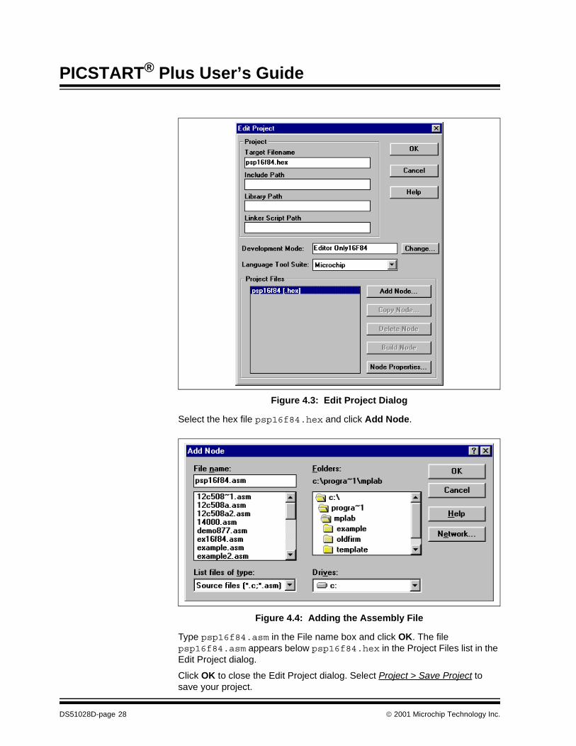
Figure 4.3: Edit Project Dialog
Select the hex file psp16f84.hex and click Add Node.
Figure 4.4: Adding the Assembly File
Type psp16f84.asm in the File name box and click OK. The file psp16f84.asm appears below psp16f84.hex in the Project Files list in the Edit Project dialog.
Click OK to close the Edit Project dialog. Select Project > Save Project to save your project.
DS51028D-page 28 2001 Microchip Technology Inc.
Programming Examples
4.2.4.2 Creating the Assembly Code
At this point, you still need to create the source code that you will assemble to create your hex file. Select File > New. An Untitled source code window will open on your MPLAB desktop.
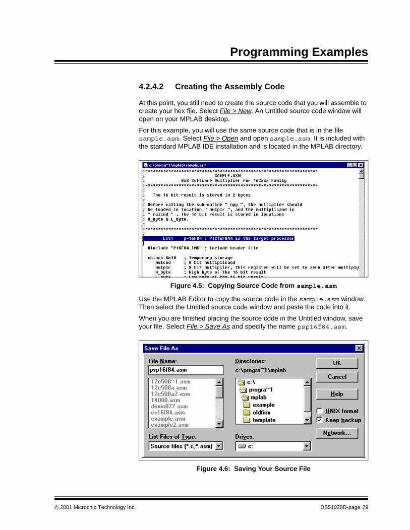
For this example, you will use the same source code that is in the file sample.asm. Select File > Open and open sample.asm. It is included with the standard MPLAB IDE installation and is located in the MPLAB directory.
Figure 4.5: Copying Source Code from sample.asm
Use the MPLAB Editor to copy the source code in the sample.asm window. Then select the Untitled source code window and paste the code into it.
When you are finished placing the source code in the Untitled window, save your file. Select File > Save As and specify the name psp16f84.asm.
Figure 4.6: Saving Your Source File
2001 Microchip Technology Inc. DS51028D-page 29
PICSTART® Plus User’s Guide
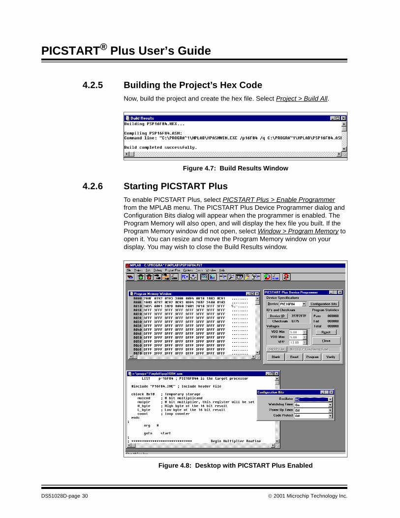
4.2.5 Building the Project’s Hex CodeNow, build the project and create the hex file. Select Project > Build All.
Figure 4.7: Build Results Window
4.2.6 Starting PICSTART PlusTo enable PICSTART Plus, select PICSTART Plus > Enable Programmer from the MPLAB menu. The PICSTART Plus Device Programmer dialog and Configuration Bits dialog will appear when the programmer is enabled. The Program Memory will also open, and will display the hex file you built. If the Program Memory window did not open, select Window > Program Memory to open it. You can resize and move the Program Memory window on your display. You may wish to close the Build Results window.
Figure 4.8: Desktop with PICSTART Plus Enabled
DS51028D-page 30 2001 Microchip Technology Inc.

Programming Examples
4.2.6.1 The PICSTART Plus Device Programmer Dialog
The PICSTART Plus Device Programmer dialog must remain open during your programming session.
Figure 4.9: Device Programmer Dialog – PIC16F84
The Device ID is useful for tracking the version of firmware on a device once it is code protected. The calibration memory tutorial incorporates instructions on using this feature (see Section 4.3.3).
You’ll use the Read, Blank Check, Program, and Verify buttons to perform those functions on an entire device.
4.2.6.2 Configuration Bits Dialog
The Configuration Bits dialog opens when you enable the programmer. If you close the Configuration Bits dialog, you can click Configuration Bits in the PICSTART Plus Device Programmer dialog to reopen it.
Figure 4.10: Setting Configuration Bits
2001 Microchip Technology Inc. DS51028D-page 31
PICSTART® Plus User’s Guide
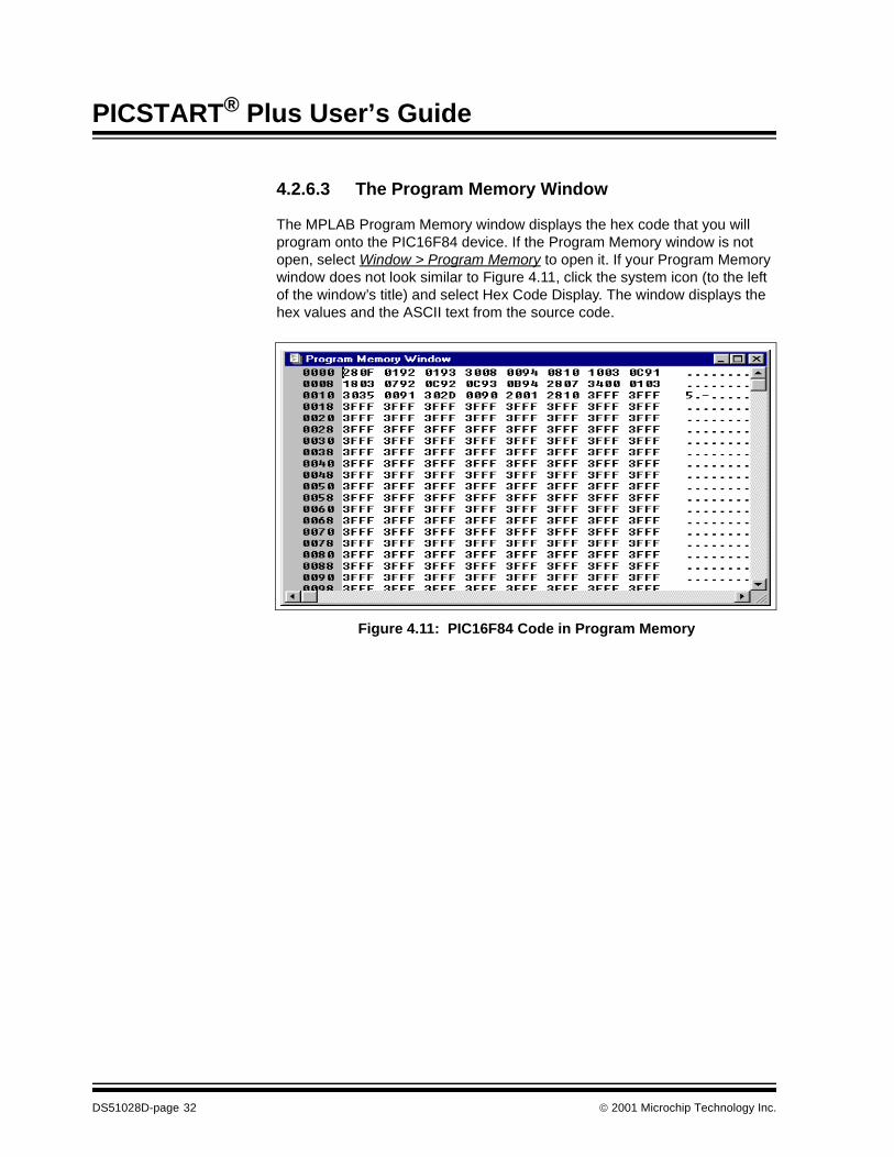
4.2.6.3 The Program Memory Window
The MPLAB Program Memory window displays the hex code that you will program onto the PIC16F84 device. If the Program Memory window is not open, select Window > Program Memory to open it. If your Program Memory window does not look similar to Figure 4.11, click the system icon (to the left of the window’s title) and select Hex Code Display. The window displays the hex values and the ASCII text from the source code.
Figure 4.11: PIC16F84 Code in Program Memory
DS51028D-page 32 2001 Microchip Technology Inc.
Programming Examples
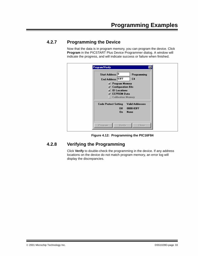
4.2.7 Programming the DeviceNow that the data is in program memory, you can program the device. Click Program in the PICSTART Plus Device Programmer dialog. A window will indicate the progress, and will indicate success or failure when finished.
Figure 4.12: Programming the PIC16F84
4.2.8 Verifying the ProgrammingClick Verify to double-check the programming in the device. If any address locations on the device do not match program memory, an error log will display the discrepancies.
2001 Microchip Technology Inc. DS51028D-page 33

PICSTART® Plus User’s Guide
4.3 Example: Programming Calibration DevicesThe two-part tutorial in this section leads you through the steps involved in programming devices that have been supplied by the factory with calibration memory.
This two-part example provides step-by-step instructions for initially programming and reprogramming a windowed PIC12C508A calibration memory device.
4.3.1 Calibration Programming Process OverviewThe steps required to initially program a new, unprogrammed calibration memory device are:
• Configuring the Serial Port for PICSTART Plus• Setting Up the MPLAB Development Mode• Enabling PICSTART Plus• Preparing for Programming a Device
- Storing Calibration Data to a File- Checking the Device and Setting the Device ID or Checksum- Checking the Configuration Bit Settings- Loading the Hex File to be Programmed
• Programming the Device• Verifying the Programming
The steps required to reprogram an erased windowed calibration memory device are:
• Configuring the Serial Port for PICSTART Plus• Setting Up the MPLAB Development Mode• Enabling PICSTART Plus• Preparing for Programming a Device
- Checking the Device and Setting the Device ID or Checksum- Checking the Configuration Bit Settings- Loading the Hex File to be Programmed- Restoring the Calibration Data from a File
• Reprogramming the Device• Verifying the Programming
4.3.2 Before You BeginBefore you can begin this tutorial, you must install the PICSTART Plus hardware (Section 3.4) and MPLAB IDE software (Section 3.5). Make sure you have read and completed the instructions in Section 3.6 through Section 3.9. Make sure that your PC and PICSTART Plus are communicating and the PICSTART Plus menu item appears on the MPLAB menu before you begin this tutorial.
DS51028D-page 34 2001 Microchip Technology Inc.

Programming Examples
4.3.3 PIC12C508A Example Part 1: Initial Programming of a Windowed Calibration Memory Device
4.3.3.1 Setting Up the MPLAB Development Mode
Select Options > Development Mode to open the Development Mode dialog (Figure 4.13).
Figure 4.13: Development Mode Dialog
Select the MPLAB SIM Simulator development mode. Select the PIC12C508A processor.
4.3.3.2 Changing the Environment Settings
A default setting in the MPLAB IDE clears all memory on download. You don’t want to do that when working with a device with calibration memory, because you want to preserve that memory in the device. Select Options > Environment Setup. Locate the Global Switches area in the General tab of the Development Mode dialog. Remove the check mark in the Clear Memory on Download check box. Select OK or Apply.
Note: When working with calibration memory, it is important that theMPLAB IDE not be in Emulator mode. This ensures that the cali-bration data is correctly loaded from the device or file, rather thanfrom the emulator probe.
2001 Microchip Technology Inc. DS51028D-page 35

PICSTART® Plus User’s Guide
4.3.3.3 Starting PICSTART Plus
To enable PICSTART Plus, select Enable Programmer from the PICSTART Plus menu.
The PICSTART Plus Device Programmer dialog (Figure 4.17) and the Configuration Bits dialog (Figure 4.19) are displayed whenever the programmer is enabled.
4.3.3.4 Storing Calibration Data
Calibration parts such as the PIC12C508A are calibrated at the factory with the calibration parameters stored in a special section of program memory. When you erase a windowed device (/JW) in order to reprogram it, you also erase its calibration data. In order for the device to operate properly once it is reprogrammed, you must restore that individual device’s calibration data. The device may not operate properly if you use another individual device’s calibration data.
Before you program a windowed device for the first time, store its calibration data in a hex file on your PC.
This tutorial will use a PIC12C508A device. Number it with a small label. For this tutorial, label the part “A.”
1. Before you place your device in the PICSTART Plus socket, selectPICSTART Plus > Erase Program Memory. This sets all bits in the Pro-gram Memory, Data Memory, and Calibration Memory windows to ‘1’.
2. Insert the part that you labeled “A” in the PICSTART Plus.3. Click Read in the PICSTART Plus Device Programmer dialog to read the
device.
Figure 4.14: Reading the Device
DS51028D-page 36 2001 Microchip Technology Inc.
Programming Examples
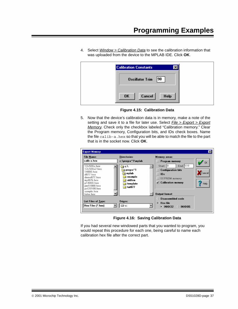
4. Select Window > Calibration Data to see the calibration information thatwas uploaded from the device to the MPLAB IDE. Click OK.
Figure 4.15: Calibration Data
5. Now that the device’s calibration data is in memory, make a note of thesetting and save it to a file for later use. Select File > Export > ExportMemory. Check only the checkbox labeled “Calibration memory.” Clearthe Program memory, Configuration bits, and IDs check boxes. Namethe file calib-a.hex so that you will be able to match the file to the partthat is in the socket now. Click OK.
Figure 4.16: Saving Calibration Data
If you had several new windowed parts that you wanted to program, you would repeat this procedure for each one, being careful to name each calibration hex file after the correct part.
2001 Microchip Technology Inc. DS51028D-page 37

PICSTART® Plus User’s Guide
4.3.3.5 Setting Up the Device Programmer Dialog
The PICSTART Plus Device Programmer dialog (Figure 4.17) is always open when PICSTART Plus is enabled. Closing this dialog will disable the programmer.
Figure 4.17: PICSTART Plus Device Programmer Dialog
The Device box shows the PIC12C508A device that you selected when you set up the development mode.
Click Device ID. Enter 0001. This will allow you to identify the version of firmware on the device after it is programmed and code-protected. Click OK.
Figure 4.18: Using Device ID to Identify Firmware or Other Information
DS51028D-page 38 2001 Microchip Technology Inc.

Programming Examples
4.3.3.6 Setting Up the Configuration Bits Dialog
The Configuration Bits dialog (Figure 4.19) opens when PICSTART Plus is enabled. If you closed the Configuration Bits dialog, reopen it by clicking Configuration Bits in the PICSTART Plus Device Programmer dialog.
Figure 4.19: Configuration Bits Dialog – PIC16F84
Use the default values for the configuration bits. Make sure Code Protect is Off.
4.3.3.7 Loading the Hex File to be Programmed
Now that you have saved the calibration data to a hex file, load the file to be programmed. Select File > Import > Import to Memory to load the hex code into the MPLAB Program Memory window. Select 12c508a.hex. It is included in the MPLAB installation.
Figure 4.20: Download Emulation Memory Dialog
2001 Microchip Technology Inc. DS51028D-page 39
PICSTART® Plus User’s Guide
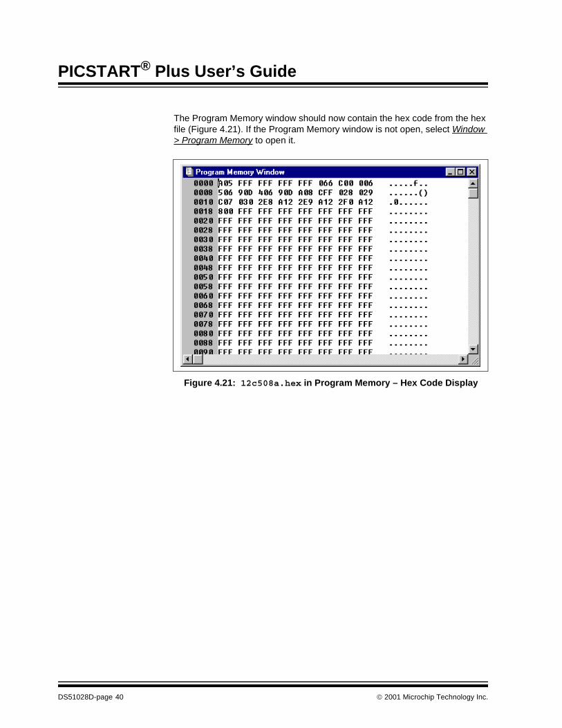
The Program Memory window should now contain the hex code from the hex file (Figure 4.21). If the Program Memory window is not open, select Window > Program Memory to open it.
Figure 4.21: 12c508a.hex in Program Memory – Hex Code Display
DS51028D-page 40 2001 Microchip Technology Inc.

Programming Examples
4.3.3.8 Programming a Calibration Device
Click Program in the PICSTART Plus Device Programmer dialog to program the entire device (all of program memory, configuration bits, etc.).
Figure 4.22: Programming the PIC12C508A
The Program/Verify dialog will appear while the device is being programmed. The areas being programmed are automatically selected based on the device.
When the programming is finished, “Success” or “Failure” will appear to the right of the Start Address. If the programming failed, an error window will appear showing the good (expected) data and the bad (actual) data for each address it attempted to program.
2001 Microchip Technology Inc. DS51028D-page 41

PICSTART® Plus User’s Guide
4.3.3.9 Verifying the Programming
Now that you have programmed a device, click Verify in the PICSTART Plus Device Programmer dialog to verify that the contents of the device match the values shown in the Program Memory window and PICSTART Plus Device Programmer dialog.
Figure 4.23: Verifying the Programming
DS51028D-page 42 2001 Microchip Technology Inc.
Programming Examples
4.3.4 PIC12C508A Example Part 2: Reprogramming A Windowed Calibration Memory Device
4.3.4.1 Before You Begin
This tutorial is intended to be used after you have completed the tutorial on initially programming a windowed device in Section 4.3.3.
Before you can reprogram the windowed part, you must erase it in a UV eraser. Remove the covering on the device’s window. Place the part in a UV eraser. The amount of time required to completely erase a UV erasable device depends on: the wavelength of the light, its intensity, distance from UV source, and the process technology of the device (the size of the memory cells). This erases the entire device, including its calibration memory. In order to work properly, the calibration memory for that individual device must be restored, by importing the calibration file you created for the chip earlier.
4.3.4.2 Setting Up the Device Programmer Dialog
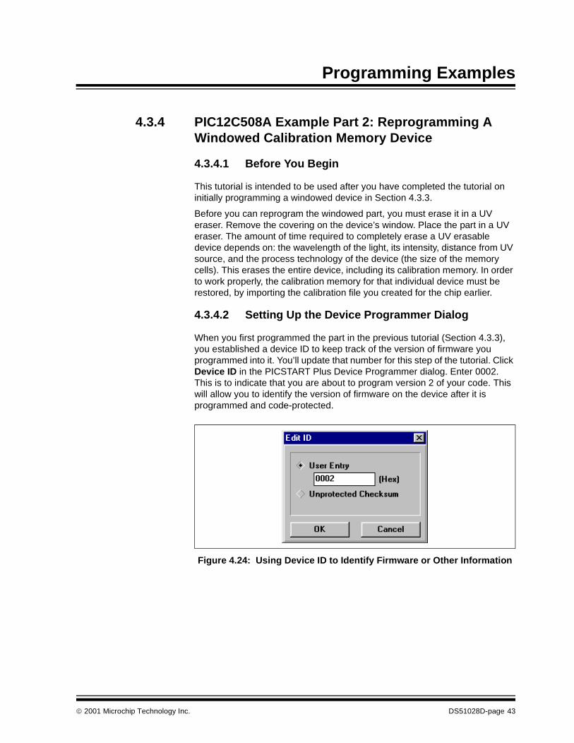
When you first programmed the part in the previous tutorial (Section 4.3.3), you established a device ID to keep track of the version of firmware you programmed into it. You’ll update that number for this step of the tutorial. Click Device ID in the PICSTART Plus Device Programmer dialog. Enter 0002. This is to indicate that you are about to program version 2 of your code. This will allow you to identify the version of firmware on the device after it is programmed and code-protected.
Figure 4.24: Using Device ID to Identify Firmware or Other Information
2001 Microchip Technology Inc. DS51028D-page 43

PICSTART® Plus User’s Guide
4.3.4.3 Setting Up the Configuration Bits Dialog
The Configuration Bits dialog opens when PICSTART Plus is enabled. If you closed the Configuration Bits dialog, reopen it by clicking Configuration Bits in the PICSTART Plus Device Programmer dialog.
Figure 4.25: Configuration Bits Dialog – PIC16F84
Use the default values for the configuration bits. Make sure Code Protect is Off.
DS51028D-page 44 2001 Microchip Technology Inc.

Programming Examples
4.3.4.4 Loading the Hex File to be Programmed
Before you load the device’s calibration data into program memory, load the file to be programmed.
Select File > Import > Import to Memory to load the hex code into the MPLAB Program Memory window. Select 12c508a2.hex. This is similar to the program you originally used to program the part, but it has been modified slightly for this exercise.
The Program Memory window should now contain the hex code from the hex file. If the Program Memory window is not open, select Window > Program Memory to open it.
Figure 4.26: Program Memory – Hex Code Display
2001 Microchip Technology Inc. DS51028D-page 45

PICSTART® Plus User’s Guide
4.3.4.5 Restoring Calibration Values to the Device
Earlier, you saved the part’s calibration data to the hex file calib-a.hex. Because the UV eraser erased that data from the device, you must rewrite it to the device in order for the reprogrammed part to operate correctly.
1. Select File > Import > Import to Memory and select the saved calibrationparameters file (calib-a.hex).
Figure 4.27: Restoring Calibration Data to an Erased Device
2. A default setting in the MPLAB IDE clears all memory on download. Youdon’t want to do that when you’re working with a device with calibrationmemory, because you want to preserve that memory in the device.Select Options > Environment Setup. Locate the Global Switches areain the General tab of the Development Mode dialog. Make sure there isno check mark in the Clear Memory on Download check box. Click OK.
4.3.4.6 Programming a Calibration Device
Click Program in the PICSTART Plus Device Programmer dialog. This will program the entire device including program memory, calibration memory, configuration bits, etc.
The Program/Verify dialog will appear while the device is being programmed. The areas being programmed are automatically selected based on the device.
When the programming is finished, “Success” or “Failure” will appear to the right of the Start Address.
DS51028D-page 46 2001 Microchip Technology Inc.
Programming Examples
4.3.4.7 Verifying the Programming
Now that you have programmed a device, click Verify in the PICSTART Plus Device Programmer dialog to verify that the contents of the device match the values shown in the Program Memory window and PICSTART Plus Device Programmer dialog.
2001 Microchip Technology Inc. DS51028D-page 47

PICSTART® Plus User’s Guide
NOTES:
DS51028D-page 48 2001 Microchip Technology Inc.

®
PICSTART PLUS USER’S GUIDE12Chapter 5. Using PICSTART Plus5.1 IntroductionThis chapter describes the steps required to program and read a device using the PICSTART Plus development programmer.
5.2 HighlightsTopics covered in this chapter:
• Procedure for Programming a Device
• Verifying the Programming
• Reading a Device
5.3 Procedure for Programming a DeviceTo program a device, you will need:
• A hex file to program into the PICmicro MCU device
• A blank PICmicro MCU device to program
Before you can program a device, you must:
• Install the PICSTART Plus hardware and MPLAB IDE software (Chapter 3)
• Establish communications between the PICSTART Plus and PC
• Set up the MPLAB IDE development mode
• Enable (start) PICSTART Plus (Section 3.9)
The following table lists the steps to program a device.
Step Description See Section
1 Set up the Device Programmer dialog Section 5.3.1
2 Set up the Configuration Bits dialog Section 5.3.2
3 Load a hex file into program memory or assemble/compile one in program mem-ory from your source code
Section 5.3.3
4 Check that your device is blank Section 5.3.5
5 Program the device Section 5.3.6
2001 Microchip Technology Inc. DS51028D-page 49

PICSTART® Plus User’s Guide
5.3.1 Setting Up the Device Programmer DialogThe PICSTART Plus Device Programmer dialog (Figure 5.1) is always open when PICSTART Plus is enabled. Closing this dialog will disable the programmer.
Figure 5.1: PICSTART Plus Device Programmer Dialog
The device list shows the device that was selected when you set up the MPLAB IDE development mode. If you wish to program a different device, you may select it here or through Options > Development Mode. However, changing the device at this point will close any open MPLAB IDE projects (unless you are in Editor Only mode) and clear the program memory, configuration bits, and ID locations.
If your device is not listed in the PICSTART Plus Device Programmer dialog, you will need to upgrade your version of MPLAB IDE software, and possibly your version of the PICSTART Plus operating system (Section 6.9).
Configuration bits are set in the Configuration Bits dialog, discussed in the next section. If you close the Configuration Bits dialog, you can reopen it by clicking Configuration Bits in this dialog.
You can edit the device ID value or program the unprotected checksum by clicking Device ID. You can reset Program Statistics by clicking Reset. The Voltages section is set to default voltages and cannot be changed.
DS51028D-page 50 2001 Microchip Technology Inc.

Using PICSTART Plus
5.3.2 Setting Up the Configuration Bits DialogThe Configuration Bits dialog (Figure 5.2) opens when PICSTART Plus is enabled. If you close the Configuration Bits dialog, you can reopen it by clicking Configuration Bits in the PICSTART Plus Device Programmer dialog.
Figure 5.2: Configuration Bits Dialog – PIC16C74A
The configuration bits shown are for a PIC16C74A device. The type and number of configuration bits depend on the device you have selected. For more information on the functions of configuration bits for your device, refer to the device data sheet.
You can specify the configuration bit values in your source code instead of entering them into the Configuration Bits dialog. Use MPASM’s _ _CONFIG directive to set the configuration bits for the device to be programmed. Each time you rebuild your project or reload your hex file, the configuration bits will be set according to the values from this directive.
If you do not set configuration bits in your source code, these bits will not be changed. If you manually change these bits from their default values using this dialog, they will be programmed into the PICmicro MCU device when you program the microcontroller.
An ID value set in the Edit ID dialog overrides any value set in the program.
Note: Setting configuration bits in the Configuration Bits dialog will noteffect emulator or simulator operation. To do so, use Options >Development Mode.
2001 Microchip Technology Inc. DS51028D-page 51
PICSTART® Plus User’s Guide
5.3.3 Loading a Hex File into Program MemoryAbout Program Memory
When PICSTART Plus is enabled, the Program Memory window will be opened in Hex Code format, if it is not already open.
You can view the Program Memory as hex code, machine code, or disassembled with symbols (if available). To change display mode, click on the system button in the upper left corner of the window and select the display mode from the system menu.
When in MPLAB ICE emulator mode, Program Memory shows the data that is in the emulation memory of the MPLAB ICE pod. This memory is read by the MPLAB ICE probe when you run, single step, or trace using the emulator.
When in MPLAB SIM simulator mode or Editor Only mode, the Program Memory window reflects the contents of a memory buffer on the PC. This memory is read by MPLAB SIM when you run, single step, or trace.
If you read program memory with PICSTART Plus while in emulator or simulator mode, it will overwrite the program memory being emulated or simulated. This can cause “mismatches” between the program memory and debug information if you have an MPLAB IDE project open. You will be given an option to close the current MPLAB IDE project or to continue and read the device’s memory into the Program Memory window. Subsequent debug operations may not work properly.
DS51028D-page 52 2001 Microchip Technology Inc.
Using PICSTART Plus
Loading a Hex File into Program Memory
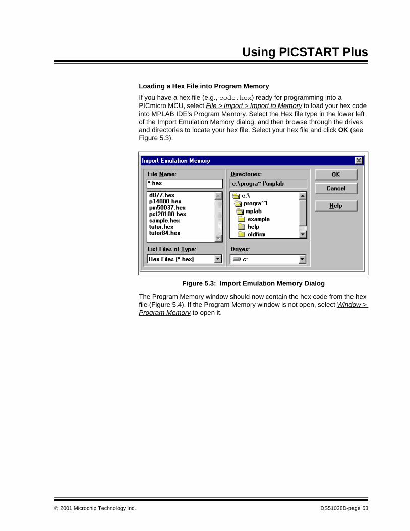
If you have a hex file (e.g., code.hex) ready for programming into a PICmicro MCU, select File > Import > Import to Memory to load your hex code into MPLAB IDE’s Program Memory. Select the Hex file type in the lower left of the Import Emulation Memory dialog, and then browse through the drives and directories to locate your hex file. Select your hex file and click OK (see Figure 5.3).
Figure 5.3: Import Emulation Memory Dialog
The Program Memory window should now contain the hex code from the hex file (Figure 5.4). If the Program Memory window is not open, select Window > Program Memory to open it.
2001 Microchip Technology Inc. DS51028D-page 53

PICSTART® Plus User’s Guide
Figure 5.4: Program Memory – Hex Code Display
If you do not have a hex file with which to program your device, you can build one using MPLAB Projects. The MPLAB IDE User’s Guide contains several tutorials that instruct you on using MPLAB Projects to develop your own firmware. Each time you rebuild your project, the Program Memory window will be updated.
5.3.4 File Formats Used by PICSTART Plus PICSTART Plus can use information directly from the MPLAB IDE projects without any intermediate steps. MPASM can be used separately from the MPLAB IDE to produce hex files for PICSTART Plus. Alternatively, devices can be programmed with hex files from any PICmicro MCU compatible cross-assembler or cross-compiler.
If you are using MPASM separate from the MPLAB IDE, or are using the MPLAB IDE to generate hex files for use with PICSTART Plus, you should use either INHX8M or INHX32 hex formats. MPASM’s default output format for hex files is INHX8M. If you are programming PIC17CXXX or PIC18CXXX devices, you should use INHX32 format. See the MPASM User’s Guide with MPLINK and MPLIB for details on file formats.
DS51028D-page 54 2001 Microchip Technology Inc.

Using PICSTART Plus
5.3.5 Checking For a Blank DeviceInsert the device to be programmed into the PICSTART Plus socket. Position pin one on the device to be in the pin one position as shown by the ‘1’ immediately to the left of the socket. Secure the device by pulling the silver lever on the socket toward you (up).
Click Blank in the PICSTART Plus Device Programmer dialog to verify that the device is completely blank (all bits are set to a ‘1’). This will also verify that all configuration bits are set to a ‘1’ (unprogrammed state). You can also perform a blank check by selecting PICSTART Plus > Blank Check All from the MPLAB menu.
If you are using a one-time programmable (OTP) device, some configuration bits might already be programmed from the factory (e.g., oscillator bits). Use the Configuration Bits dialog to set the configuration bits to the factory settings and then select PICSTART Plus > Blank Check OTP. This will check that all program memory bits are set to ‘1’ and that the configuration bits match the value in the dialog. An OTP device cannot be erased and reprogrammed.
If the EPROM device is not blank, you will have to erase it before programming. To erase a windowed device:
1. Remove any labels covering the device window. If you do not have a win-dowed device (Figure 5.5), you cannot reprogram it. A windowed versionof all EPROM devices may be ordered by requesting the JW package.
Figure 5.5: Windowed Device
2. Place the device in an Ultraviolet (UV) EPROM Eraser. The amount oftime required to completely erase a UV erasable device depends on: thewavelength of the light, its intensity, distance from UV source, and theprocess technology of the device (the size of the memory cells).
3. Before attempting to program the device, perform the blank check againto verify that it is blank.
If the device is EEPROM/FLASH, you do not have to erase it before reprogramming it. These devices are electrically erased before programming.
2001 Microchip Technology Inc. DS51028D-page 55

PICSTART® Plus User’s Guide
5.3.6 Programming a DeviceTo program the entire device (i.e., all of program memory, configuration bits, etc.), click Program in the PICSTART Plus Device Programmer dialog.
To program selectively (e.g., part of program memory, only configuration bits), select PICSTART Plus > Program/Verify to open the Program/Verify dialog (Figure 5.6). Select the options for programming, then click Program in the Program/Verify dialog to program the device.
Figure 5.6: Program/Verify Dialog
To compare the contents of the device to the values shown in the MPLAB IDE, click Verify. Close will exit the dialog.
To selectively program, you will need to adjust the following settings in the Program/Verify dialog. The memory area corresponding to the checked boxes will be programmed. Areas that are grayed out are not available on the device.
Start Address The starting address in program memory for programming or verification.
End Address The ending address in program memory for programming or verification.
Program Memory Program or verify the program memory for the range specified by Start Address and End Address.
Configuration Bits Program or verify the configuration bits.
ID Locations Program or verify the ID locations. You can set the ID locations using the PICSTART Plus Device Programmer dialog.
DS51028D-page 56 2001 Microchip Technology Inc.

Using PICSTART Plus
5.4 Verifying the ProgrammingClick Verify in the PICSTART Plus Device Programmer dialog or the Program/Verify dialog to verify that the contents of the device match the program memory, EEPROM data, calibration memory, ID locations, and configuration bits in the MPLAB IDE and in the PICSTART Plus Device Programmer dialog and Configuration Bits dialog.
EEPROM Data For devices with data EEPROM, program or verify the data memory from data in the EEPROM Memory window. Refer to the MPLAB IDE User’s Guide for more information on data EEPROM and the EEPROM Memory window.
Calibration Memory For devices with calibration memory, program or verify the calibration memory from data in the Calibration Memory window. Refer to the MPLAB IDE User’s Guide for more information on calibration memory and the Calibration Memory window.
Code Protect Settings Shows the status and availability of code pro-tection for the selected device.
2001 Microchip Technology Inc. DS51028D-page 57

PICSTART® Plus User’s Guide
5.5 Reading a DeviceTo copy the firmware from a programmed PICmicro MCU device into an unprogrammed device, you first read the programmed firmware (program memory, configuration bits, etc.) into the MPLAB IDE, and then program the new device based on this information.
To read the entire device (e.g., all of program memory, configuration bits, etc.), click Read in the PICSTART Plus Device Programmer dialog.
To read selectively (e.g., part of program memory, only configuration bits, etc.), select PICSTART Plus > Read Device to display the Read Device dialog (Figure 5.7). Select the options to be read, and then click Read in the Read Device dialog to read the device. The memory area corresponding to the checked boxes will be read. Areas that are grayed out are not available on the device. Close will exit the dialog.
Figure 5.7: Read Device Dialog
To selectively read, adjust the following settings in the Read Device dialog.
Start Address The starting address in program memory for reading.
End Address The ending address in program memory for reading.
Program Memory Read the program memory for the range speci-fied by Start Address and End Address.
Configuration Bits Read the configuration bits.
ID Locations Read the ID locations.
DS51028D-page 58 2001 Microchip Technology Inc.

Using PICSTART Plus
Once the Read is complete, the Program Memory window will display the data read from the device master. You can then:
• Modify the data in the MPLAB IDE by selecting Window > Modify before you save to a hex file or program another device
• Save the data as a hex file by selecting File > Export > Export Memory
• Insert a new device into PICSTART Plus to copy the data into it
If you have any problems when attempting to read a device, refer to Appendix C.
EEPROM Data For devices with data EEPROM, read the data in the data memory into the EEPROM Memory window. For more information on data EEPROM and the EEPROM Memory window, refer to the MPLAB IDE User’s Guide.
Calibration Memory For devices with calibration memory, read the data in the calibration memory into the Calibra-tion Memory window. For more information on calibration memory and the Calibration Memory window, refer to the MPLAB IDE User’s Guide.
Note: If you have an MPLAB ICE emulator connected to the MPLAB IDE,your code will be downloaded to the emulated program memory ofthe MPLAB ICE. If you have a project open, you will be asked ifyou want to close it before reading memory from a device. If youkeep your project open, the Absolute Listing window and theSource Code window may not match the data you have read intothe Program Memory window. Symbols may not match the properaddresses in the Program Memory window.
2001 Microchip Technology Inc. DS51028D-page 59

PICSTART® Plus User’s Guide
NOTES:
DS51028D-page 60 2001 Microchip Technology Inc.
®
PICSTART PLUS USER’S GUIDE12Chapter 6. PICSTART Plus – Reference6.1 IntroductionThis chapter describes the dialogs, windows, and menu items of the PICSTART Plus development system.
6.2 HighlightsTopics covered in this chapter:
• PICSTART Plus Device Programmer Dialog
• Configuration Bits Dialog
• Program Memory Window
• Program/Verify Dialog
• Read Device Dialog
• PICSTART Plus Menu Items
• Upgrading the PICSTART Plus Operating System
2001 Microchip Technology Inc. DS51028D-page 61

PICSTART® Plus User’s Guide
6.3 PICSTART Plus Device Programmer DialogThe PICSTART Plus Device Programmer dialog (Figure 6.1) is displayed whenever the programmer is enabled. Closing the PICSTART Plus Device Programmer dialog will disable the programmer. The options in the dialog will show the current values if active, or will be disabled (grayed out). The Voltage section is set to default voltages and cannot be changed.
Figure 6.1: PICSTART Plus Device Programmer Dialog
To program a device, you will need to set the following options in the PICSTART Plus Device Programmer dialog.
Device Sets the PICmicro MCU device type to use with PICSTART Plus. The default is the device that was selected when you set up the development mode.
Note: Setting the device type here will close anyopen MPLAB IDE projects (except in Edi-tor Only mode) and clear the programmemory, configuration bits, and ID locations.
DS51028D-page 62 2001 Microchip Technology Inc.
PICSTART Plus – Reference
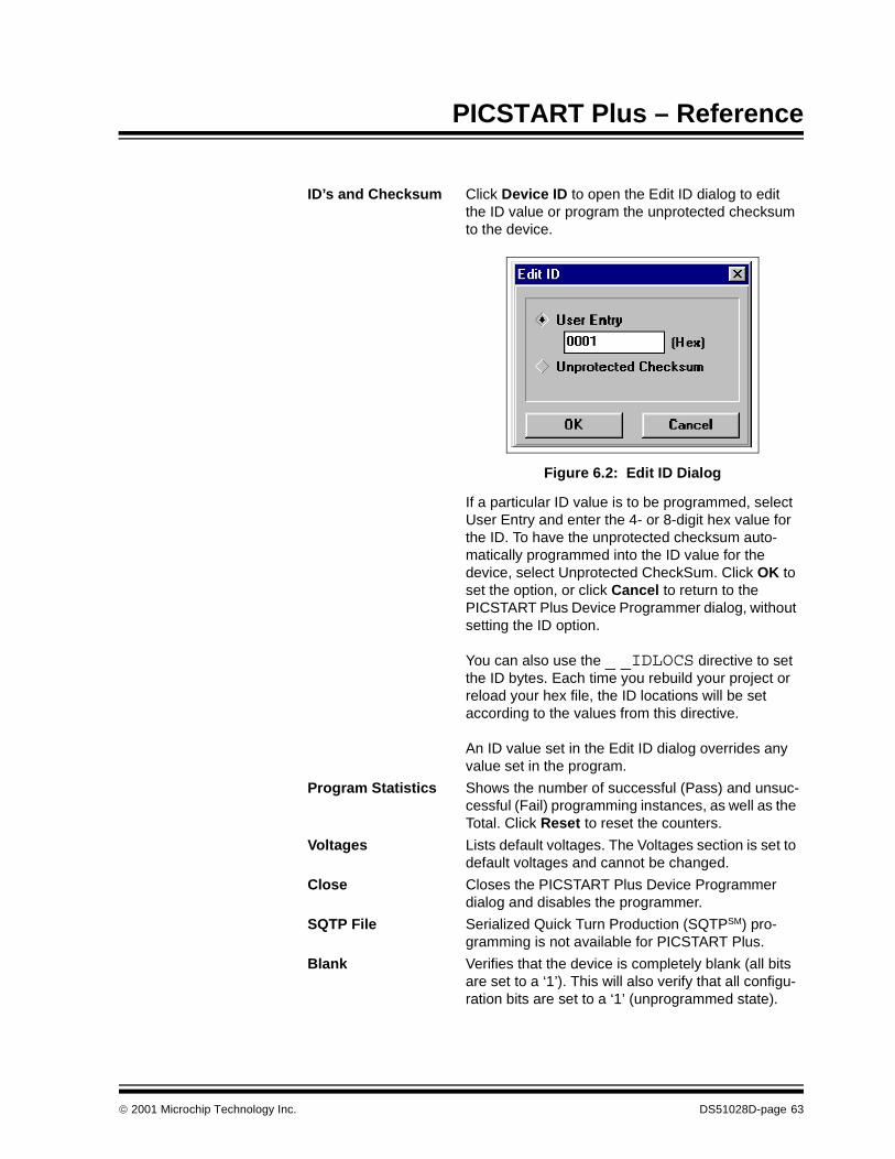
ID’s and Checksum Click Device ID to open the Edit ID dialog to edit the ID value or program the unprotected checksum to the device.
Figure 6.2: Edit ID Dialog
If a particular ID value is to be programmed, select User Entry and enter the 4- or 8-digit hex value for the ID. To have the unprotected checksum auto-matically programmed into the ID value for the device, select Unprotected CheckSum. Click OK to set the option, or click Cancel to return to the PICSTART Plus Device Programmer dialog, without setting the ID option.
You can also use the _ _IDLOCS directive to set the ID bytes. Each time you rebuild your project or reload your hex file, the ID locations will be set according to the values from this directive.
An ID value set in the Edit ID dialog overrides any value set in the program.
Program Statistics Shows the number of successful (Pass) and unsuc-cessful (Fail) programming instances, as well as the Total. Click Reset to reset the counters.
Voltages Lists default voltages. The Voltages section is set to default voltages and cannot be changed.
Close Closes the PICSTART Plus Device Programmer dialog and disables the programmer.
SQTP File Serialized Quick Turn Production (SQTPSM) pro-gramming is not available for PICSTART Plus.
Blank Verifies that the device is completely blank (all bits are set to a ‘1’). This will also verify that all configu-ration bits are set to a ‘1’ (unprogrammed state).
2001 Microchip Technology Inc. DS51028D-page 63
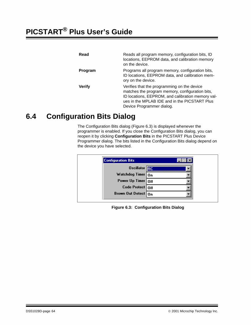
PICSTART® Plus User’s Guide
6.4 Configuration Bits DialogThe Configuration Bits dialog (Figure 6.3) is displayed whenever the programmer is enabled. If you close the Configuration Bits dialog, you can reopen it by clicking Configuration Bits in the PICSTART Plus Device Programmer dialog. The bits listed in the Configuration Bits dialog depend on the device you have selected.
Figure 6.3: Configuration Bits Dialog
Read Reads all program memory, configuration bits, ID locations, EEPROM data, and calibration memory on the device.
Program Programs all program memory, configuration bits, ID locations, EEPROM data, and calibration mem-ory on the device.
Verify Verifies that the programming on the device matches the program memory, configuration bits, ID locations, EEPROM, and calibration memory val-ues in the MPLAB IDE and in the PICSTART Plus Device Programmer dialog.
DS51028D-page 64 2001 Microchip Technology Inc.
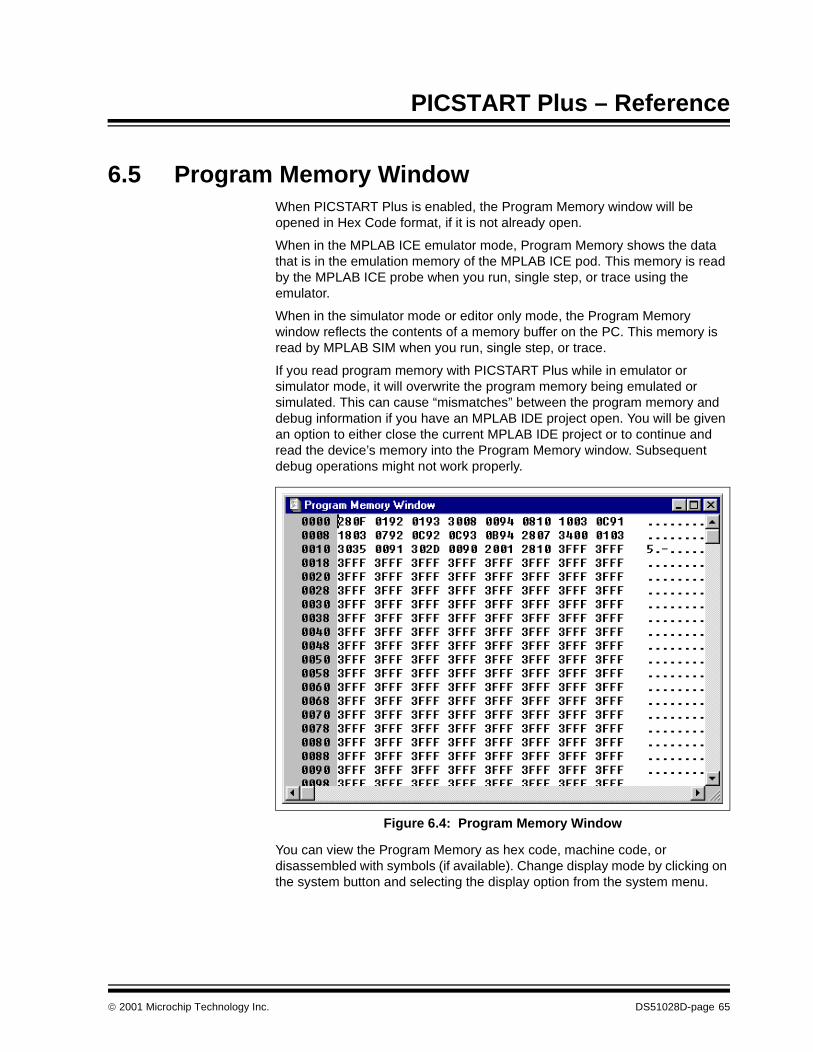
PICSTART Plus – Reference
6.5 Program Memory WindowWhen PICSTART Plus is enabled, the Program Memory window will be opened in Hex Code format, if it is not already open.
When in the MPLAB ICE emulator mode, Program Memory shows the data that is in the emulation memory of the MPLAB ICE pod. This memory is read by the MPLAB ICE probe when you run, single step, or trace using the emulator.
When in the simulator mode or editor only mode, the Program Memory window reflects the contents of a memory buffer on the PC. This memory is read by MPLAB SIM when you run, single step, or trace.
If you read program memory with PICSTART Plus while in emulator or simulator mode, it will overwrite the program memory being emulated or simulated. This can cause “mismatches” between the program memory and debug information if you have an MPLAB IDE project open. You will be given an option to either close the current MPLAB IDE project or to continue and read the device’s memory into the Program Memory window. Subsequent debug operations might not work properly.
Figure 6.4: Program Memory Window
You can view the Program Memory as hex code, machine code, or disassembled with symbols (if available). Change display mode by clicking on the system button and selecting the display option from the system menu.
2001 Microchip Technology Inc. DS51028D-page 65

PICSTART® Plus User’s Guide
6.6 Program/Verify DialogTo program or verify selectively (e.g., part of program memory, only configuration bits, etc.), select PICSTART Plus > Program/Verify to open the Program/Verify dialog (Figure 6.5).
Figure 6.5: Program/Verify Dialog
Select the options for programming or verifying. Then click Program in this dialog to program the device. The memory area corresponding to the checked boxes will be programmed. Areas that are grayed out are not available on the device.
Click Verify to verify that the programming on the device matches the program memory, configuration bits, ID locations, EEPROM, and calibration memory values in the MPLAB IDE and in the PICSTART Plus Device Programmer dialog and Configuration Bits dialog.
Start Address The starting address in program memory for pro-gramming or verification.
End Address The ending address in program memory for pro-gramming or verification.
Program Memory Program or verify the program memory for the range specified by Start Address and End Address.
Configuration Bits Program or verify the configuration bits.
ID Locations Program or verify the ID locations. You can set the ID locations using the PICSTART Plus Device Pro-grammer dialog.
DS51028D-page 66 2001 Microchip Technology Inc.

PICSTART Plus – Reference
6.7 Read Device DialogTo read selectively (e.g., part of program memory, only configuration bits, etc.), select PICSTART Plus > Read Device to display the Read Device dialog (Figure 6.6). Select the options to be read, and then click Read in this dialog to read the device. The memory area corresponding to the checked boxes will be read. Areas that are grayed out are not available on the device. Close will exit the dialog.
Figure 6.6: Read Device Dialog
To selectively read, you will need to adjust the following settings in the Read Device dialog.
EEPROM Data For devices with data EEPROM, program or verify the data memory from data in the EEPROM Mem-ory window. Refer to the MPLAB IDE User’s Guide for more information on data EEPROM and the EEPROM Memory window.
Calibration Memory For devices with calibration memory, program or verify the calibration memory from data in the Cali-bration Memory window. Refer to the MPLAB IDE User’s Guide for more information on calibration memory and the Calibration Memory window.
Code Protect Settings Shows the status and availability of code protection for the selected device.
Start Address The starting address in program memory for reading.
End Address The ending address in program memory for reading.
Program Memory Read the program memory for the range specified by Start Address and End Address.
Configuration Bits Read the configuration bits.
ID Locations Read the ID locations.
2001 Microchip Technology Inc. DS51028D-page 67

PICSTART® Plus User’s Guide
6.8 PICSTART Plus Menu ItemsThe PICSTART Plus menu items perform the following functions:
• Enable/Disable Programmer – Enables or disables the programmer. Once the programmer is enabled, this menu item changes to Disable Programmer.
• Program/Verify – Opens the Program/Verify dialog which allows you to program the device selectively (e.g., program part of program memory, or only configuration bits), or to verify that the device was programmed properly.
• Read Device – Opens the Read Device dialog which allows you to read the device selectively (e.g., part of program memory, only configuration bits of the device).
• Blank Check All – Checks that the device is completely blank (all bits are set to a ‘1’). This will also check that all configuration bits are set to a ‘1’ (unprogrammed state).
• Blank Check OTP – This function is intended for use with OTP devices that come with factory programmed configuration bits. Before using this function, set the displayed configuration bits to match the factory pro-grammed settings. The function verifies that all program memory bits are set to ‘1’ and that the configuration bits match the settings displayed in the Configuration Bits dialog.
• Display Error Log – When you have programmed a device or verified a device, an error window will show you data from memory in the device, that do not match the corresponding memory in the MPLAB IDE.
EEPROM Data For devices with data EEPROM, read the data in the data memory into the EEPROM Memory window. For more information on data EEPROM and the EEPROM Memory window, refer to the MPLAB IDE User’s Guide.
Calibration Memory For devices with calibration memory, read the data in the calibration memory into the Calibration Memory window. For more information on calibration memory and the Calibration Memory window, refer to the MPLAB IDE User’s Guide.
Note: If you have an MPLAB ICE connected to the MPLAB IDE, yourcode will be downloaded to the emulated program memory of theMPLAB ICE. If you have a project open, you will be asked if youwant to close it before reading memory from a device. If you keepyour project open, the Absolute Listing window and the SourceCode window may not match the data you have read into the Pro-gram Memory window. Symbols may not match the properaddresses in the Program Memory window.
DS51028D-page 68 2001 Microchip Technology Inc.
PICSTART Plus – Reference
• Erase Program Memory – Sets all bits in MPLAB IDE Program Mem-ory, Calibration Memory, and Data Memory (if applicable) to ‘1’.
• Erase Configuration Bits – Sets all available configuration bits and ID location bits to ‘1’. If you reload your hex file or your project after using this menu item to erase configuration bits, the values in the Configura-tion Bits dialog will be updated to reflect the newly loaded configuration bit data in your hex file or code. You can select this menu item after you have loaded your hex file or rebuilt your project, if you want to override the configuration bit values in your hex file or code.
• Reset Programmer – Resets the PICSTART Plus hardware and reestablishes RS-232 communications. Use this option if power has been disconnected from the PICSTART Plus. This option does not reset programming information in the Program Memory window, configuration bits, or IDs.
6.9 Upgrading the PICSTART Plus Operating SystemThe PICSTART Plus operating system may need to be upgraded periodically to support new devices. You can obtain these upgrades on our web site at http://www.microchip.com. To install the upgrade, perform the steps in this section.
Required Equipment
• PICSTART Plus programmer with the MPLAB IDE software
• Blank/erased PIC17C44 microcontroller (25 MHz or faster)
• Upgrade hex file (e.g., psf20100.hex) from the Microchip web site (http://www.microchip.com)
• Phillips head screwdriver
Before You Begin
PICSTART Plus hardware and the MPLAB IDE software should be installed and the programmer should be communicating with the PC via a serial port. See Section 3.4 for installation procedures and Section 3.7 for serial port configuration information.
Note: This file is included with the latest version of MPLAB IDE.Most likely, you will need new MPLAB IDE software and newPICSTART Plus software drivers to take advantage of thefeatures in the new operating system.
2001 Microchip Technology Inc. DS51028D-page 69

PICSTART® Plus User’s Guide
Procedure
1. Select Options > Development Mode. Set up MPLAB IDE’s developmentmode as follows: Editor Only, PIC17C44 device.
2. Select PICSTART Plus > Enable to enable the PICSTART Plus programmer.3. Ensure that the PIC17C44 is the selected device in the Device Program-
mer dialog. If not, select it from the Device list in the PICSTART PlusDevice Programmer dialog.
4. If the Configuration Bits dialog is not displayed, click Configuration Bitsin the PICSTART Plus Device Programmer dialog. Set the configurationbits in the Configuration Bit dialog as described below:
- Oscillator: XT- Processor Mode: Microcontroller - Watchdog Timer: TMR
5. Select File > Import > Import to Memory to import the upgrade hex fileinto the MPLAB IDE’s program memory. Select the upgrade hex file andclick OK.
6. Insert the PIC17C44 microcontroller into PICSTART Plus socket andclick Blank in the PICSTART Plus Device Programmer dialog, to checkthat it is blank (see Section 5.3.5). If the device is not blank, it must beerased before programming.
7. Click Program in the PICSTART Plus Device Programmer dialog to pro-gram the hex file into the device.
8. Remove the PIC17C44 from the programming socket and label it withthe upgrade version (e.g., VER 2.01.00).
9. Exit the MPLAB IDE and disconnect the PICSTART Plus from the com-puter serial port and power supply.
10. Carefully remove the four Phillips head screws from the back of thePICSTART Plus. Remove the back cover.
11. Remove the PICSTART Plus PCB from the housing.12. Carefully remove the PIC17C44 from the PICSTART Plus PCB. Save
this version as it may be needed for future upgrades.13. Carefully insert the PIC17C44 you just programmed into the socket,
making sure that Pin 1 is properly oriented (Pin 1 should be close to theserial port connector).
14. Place the PICSTART Plus PCB back into the housing.15. Carefully insert the Phillips head screws into the holes in the back cover,
then tighten each screw slowly. The plastic housing can be damaged iftoo much torque is applied to the screws.
16. Reconnect the PICSTART Plus programmer to the computer serial portand power supply.
17. Start the MPLAB IDE software and enable the PICSTART Plus programmer.18. As the programmer is being enabled, the dialog box will indicate the
PICSTART Plus operating system version. You can also check the ver-sion by selecting Help > About MPLAB and locating PICSTART Plus inthe list of Registered Applications.
Your PICSTART Plus operating system is now upgraded.
DS51028D-page 70 2001 Microchip Technology Inc.

®
PICSTART PLUS USER’S GUIDE12Appendix A. Connecting to a 25-Pin Serial PortA.1 IntroductionThis appendix describes how to connect the PICSTART Plus programmer to a 25-pin serial port.
A.2 HighlightsTopics covered in this appendix:
• Connection Description
A.3 Connection DescriptionThe following table provides the data for connecting the PICSTART Plus programmer (9-pin straight-through) to a 25-pin serial port. Connect the corresponding terminals indicated on each line of the table.
Table A.1: PC Host to PICSTART Plus Signals
25-pin (PC-Host) 9-pin (PICSTART Plus)
2 TX 2 RX
3 RX 3 TX
20 DTR 4 DTR
7 Common 5 Common
6 DSR 6 +5 volts (pulled up)
4 RTS 7 CTS
5 CTS 8 RTS
2001 Microchip Technology Inc. DS51028D-page 71

PICSTART® Plus User’s Guide
NOTES:
DS51028D-page 72 2001 Microchip Technology Inc.

®
PICSTART PLUS USER’S GUIDE12Appendix B. PICSTART Plus VPP AdjustmentB.1 IntroductionThis appendix describes how to change the VPP programming voltage of older PICSTART Plus hardware units to comply with revised programming specifications.
B.2 HighlightsTopics covered in this appendix:
• Overview
• Procedure
• Validation
B.3 OverviewIn order to remain current with Microchip’s programming specifications, any PICSTART Plus, Revision 7 or lower, might need a slight adjustment of the VPP voltage. This adjustment will bring the VPP voltage from a nominal 13.75 volts to a nominal 13.00 volts. This is due to the update of the programming specifications, after the introduction of the PICSTART Plus.
B.4 ProcedureTo identify the revision of PICSTART Plus, look at the label on the back. The serial number will end in a -Rx, where x is the current revision of the PICSTART Plus (e.g., -R7 or -R13). If this number is -R7 or lower, use one of the following two methods to adjust the VPP voltage to the nominal 13.00V:
Method 1:
Locate resistor R4, and solder a 562 kOhm 1% resistor across R4. This will lower the value of R4 and lower the VPP voltage to a nominal 13.00V.
Method 2:
Locate resistor R4, and remove R4 and replace with a 22.6 kOhm 1% resistor. This will lower the VPP voltage to a nominal 13.00V.
B.5 ValidationAfter completing the procedure, apply 9V to the PICSTART Plus and measure the voltage across Capacitor C5. It should be a nominal 13.00 (12.75 – 13.25) volts. If the voltage is correct, the modification is complete. If not, make sure that the procedure was properly followed and there are no solder shorts near the rework area.
2001 Microchip Technology Inc. DS51028D-page 73

PICSTART® Plus User’s Guide
NOTES:
DS51028D-page 74 2001 Microchip Technology Inc.

®
PICSTART PLUS USER’S GUIDE12Appendix C. TroubleshootingC.1 IntroductionThis appendix describes some common problems associated with using PICSTART Plus and steps to follow to resolve those problems.
C.2 HighlightsTopics covered in this appendix:
• Common Problems
C.3 Common Problems MPLAB IDE displays this message: “Failed to Establish Communication.”
MPLAB IDE attempts to establish communication with the PICSTART Plus device programmer upon enabling the programmer. If communication cannot be established, no programming can occur. A dialog box appears if the attempt to establish communication fails. If a communication attempt fails, try again after correcting the problem, or cancel.
SOLUTIONS:
• Make sure that the RS-232 cable is connected, the power supply is con-nected, and the Power LED on the PICSTART Plus is on.
• Try connecting the PICSTART Plus to a different serial port. If your PC has a 25-pin serial port, you will need a 25-to-9 serial port adapter.
• Make sure that a COM port is properly set up exclusively for use by PICSTART Plus. Check the resources to ensure they are operating properly and that there are no conflicts with other devices. This com-monly happens when you have a modem or other serial device that is improperly configured. Consult your Windows manual, or other refer-ence literature. You can try removing, reconfiguring, or disabling the conflicting device, but do so only if you are familiar with those proce-dures. See the steps below for Windows 3.1 or Windows 95/98.
• Some system errors are caused by driver and hardware incompatibility. See the steps below for Windows 95/98.
2001 Microchip Technology Inc. DS51028D-page 75

PICSTART® Plus User’s Guide
• If you have a COM port but the MPLAB IDE will not let you select it (the option is grayed out), you may be able to assign the port manually by editing the mplab.ini file. Typically, this occurs if you have a gap in your COM port list (e.g., you have a COM1, COM2, and a COM4, but no COM3). In this case, you may be able to fix it by opening mplab.ini (use FIND to locate this file) and editing the section called [programmers], so that the setting CommPort=1 is set to the port you want selected. This is just a work-around to a deeper problem, in which the Windows operating system is incorrectly reporting port availability through the 16-bit driver.
• You must use the Microsoft Windows communications driver that is native to the version of Windows that you use. If you use Windows 3.10, look for the file COMM.DRV in your \WINDOWS\SYSTEM directory. That file MUST have a time of 3:10a. The time denotes the version. If you are using Windows for Workgroups, look for the same file as above, but the time stamp on that file should be 3:11a. If these files differ, you may need to reinstall the Windows operating system, or install that file from another source. This problem is not likely to occur in Windows 95/98.
• Make sure you are not using a third party communications driver. Open your system.ini file and look for the line in the [OPTIONS] section that reads
COMM.DRV=COMM.DRV
If this line reads differently, you are using a different communicationsdriver.
Windows 3.1:
A serial mouse will use a COM port, as will an external modem. An internalmodem has its own COM port, so if you have a second COM port on yourPC, set it so it won’t conflict with either the mouse or the modem.
Windows 95/98, Windows NT, Windows 2000:
Windows 95/98, Windows NT, and Windows 2000 require special attentionto setting up COM ports. If you suspect a driver - hardware incompatibility,try changing Flow Control to Hardware and/or turning off the FIFO for theserial port. This is done in the Control Panel.
In Windows 95/98, click the System Icon. Click the Device Manager tab,and click Ports. If necessary, expand the Ports selection by clicking the “+”sign next to it. Double-click the I/O port that PICSTART Plus is connectedto. This is where you can set flow control to Hardware. To turn off FIFO,click the Advanced button, deselect the Use FIFO box, and click OK.
In Windows NT, click the Ports Icon. Select the COM port, click Settings,and then click the Advanced button. Deselect the FIFI box, and click OK.
In Windows 2000, click the System Icon. Click the Hardware tab, and clickthe Device Manager button. If necessary, expand the Ports selection byclicking the “+” sign next to it. Double-click the I/O port that PICSTART Plusis connected to. This is where you can set flow control to Hardware. To turnoff FIFO, click the Port Settings tab, and click the Advanced button.Deselect the Use FIFO box, and click OK.
DS51028D-page 76 2001 Microchip Technology Inc.
Troubleshooting
No PICSTART Plus Menu Visible
If you have been using another programmer (e.g., PRO MATE II), the PICSTART Plus menu might not be available.
SOLUTION:
Select Options > Programmer Options > Select Programmer to open the Select Programmer dialog, and choose PICSTART Plus from the list. After you select the programmer, MPLAB IDE will issue you a warning prompt and shut itself down. You must restart MPLAB IDE before the programmer options are available. The PICSTART Plus menu will appear on the menu bar when you restart MPLAB IDE.
Operating System Update Needed
If the device you selected when setting up the development mode in MPLAB IDE is not supported by the PICSTART Plus operating system, a message box will appear when you try to enable the programmer.
SOLUTION:
Upgrade your version of the PICSTART Plus operating system as described in Section 6.9. Make sure to get the latest versions for MPLAB IDE software and PICSTART Plus operating system (Section 6.9).
When trying to enable the PICSTART Plus with the MPLAB IDE this message appears: “Incompatible Software and Operating System Versions.”
The versions of software and operating system are mixed. PICSTART Plus and the MPLAB IDE include compatibility checks to ensure that version requirements are met.
SOLUTION:
Make sure to get the latest versions for the MPLAB IDE software and PICSTART Plus operating system (Section 6.9).
MPLAB IDE displays this message: “Hex file not found.”
The project did not generate a hex file.
SOLUTION:
Check the Make Project panel on MPLAB IDE to ensure that a hex file is being generated when you assemble or compile. Errors in your code will prevent hex file generation.
MPLAB IDE displays this message: “Program memory contains code protected data. Proceed with programming?”
Program memory contains data that was read from a code protected device. Most or all of this data is not usable.
SOLUTION:
Obtain the original hex code from a file or a nonprotected device.
2001 Microchip Technology Inc. DS51028D-page 77

PICSTART® Plus User’s Guide
When reading a device MPLAB IDE gives the following warning message: “Device is code protected. Program memory may be invalid.”
If you attempt to read a code protected device, you will get this warning.
SOLUTION:
Obtain the original hex code from a file or a nonprotected device.
Available menu functions are not operating.
Like many other applications, MPLAB IDE and PICSTART Plus use Borland’s bwcc.dll. Therefore, other versions of this DLL may interfere with tool operation.
SOLUTION:
Verify what other copies of this DLL exist on your machine and make sure they are all the latest available version (BWCC.DLL is backward compatible). Then, reboot your machine and execute the MPLAB IDE.
Blank Check failed on a known blank mid-range device.
PICSTART Plus operating system versions prior to v1.01.16 would erroneously program the first ID location upon the first access to the device after power-up. Version 1.01.00 did this sporadically, v1.01.06 did this consistently.
SOLUTION:
Upgrade to the latest operating system version following the procedure outlined in Section 6.9.
PIC16C73, PIC16C74: known blank part shows to be nonblank.
When programming some PIC16C7X (PIC16C73, PIC16C74) devices, a known blank part will show to be not blank and will not program properly. The problem occurs because the rise time of VPP is too fast to properly set the part into programming mode. This occurs only on certain date codes of parts and only on non-PIC16C7XA parts.
SOLUTION:
Insert a 0.01 µF capacitor between VPP (Pin 1) and ground (Pin 8) of the socket before inserting part. This will slow the VPP rise time and allow the device to enter programming mode.
When reading a blank PIC16C55A or PIC16C57C, program memory values of 0xBFF are reported.
The oscillator circuit for these devices is different from that of previous devices, and can cause contention during the read operation.
SOLUTION:
Use a stand-off socket with OSC2 (pin 26) clipped.
DS51028D-page 78 2001 Microchip Technology Inc.
Troubleshooting
Program and reading problems with PIC16F87X Devices.
PIC16F87X devices are shipped with low-voltage programming enabled.
PICSTART Plus uses the high-voltage programming method. Some devices do not exit programming mode properly if low-voltage programming is enabled, resulting in invalid read and programming operations.
SOLUTION:
Place a 10 kOhm resistor between the RB3 pin and one of the ground pins on the programming socket. Refer to the device data sheet for the pinout of the specific device.
A power interruption occurred.
PICSTART Plus v1.20 and greater can account for power interruptions between functions. Earlier versions do not.
SOLUTION:
If a power interruption occurs using an earlier version of the PICSTART Plus DLL, apply power to the programmer and reselect the desired device from the Programmer Status window.
LEDs flicker or power LED does not come on.
Wrong part selected and thermal fuse is blown, or device inserted wrong and thermal fuse is blown.
SOLUTION:
Remove the device and cycle power on the PICSTART Plus to reset the internal thermal fuse.
Power LED does not light.
Incompatible power supply or power supply polarity is reversed.
SOLUTION:
Make certain power supply used is the one included with the PICSTART Plus, or a compatible one as specified in Section 3.4.2. If the unit still does not turn on, contact Microchip support.
When importing a 14- or 16-bit hex file for a 12- or 14-bit device, PICSTART Plus programs the device without errors, but a manual verify fails.
SOLUTION:
MPLAB IDE automatically truncates the hex file to fit the core size. For example, if you generate a hex file containing value AAAAh and then load the file for a 14-bit device, the value displayed is 2AAAh. PICSTART Plus will program the device without errors. However, because the value being stored in memory is AAAAh, manual verify will fail.
Values put into program memory by loading a hex file or the Modify dialog, should be truncated to the core size.
2001 Microchip Technology Inc. DS51028D-page 79

PICSTART® Plus User’s Guide
NOTES:
DS51028D-page 80 2001 Microchip Technology Inc.
12 PICSTART® PLUS USER’S GUIDE
Index
Symbols_ _CONFIG .................................................... 51_ _IDLOCS ..................................................... 63
BBlank Check All ........................................ 55, 68Blank Check OTP ............................... 11, 55, 68
CCalibration Data .............................................. 12
Restoring .................................................. 46Storing ...................................................... 36
Calibration Memory ........................................ 59Programming ..................................... 57, 67Programming Example ............................ 34Read Device ...................................... 59, 68Reading .............................................. 59, 68
Calibration MemoryProgramming ........................................... 34
CE Compliance .............................................. 14Code Protect .................................................. 78
Settings .............................................. 57, 67Common Problems ......................................... 75Communication Port ....................................... 71Communications Port ................... 15, 17, 21, 75Components ................................................... 14Configuration Bits
Dialog ................................................. 31, 51Erasing ..................................................... 69Program/Verify ......................................... 56Read Device ............................................ 58Setting ...................................................... 11
Copying Firmware from Programmed Device ....................................... 58Customer Support ............................................ 8
DDefault Voltages ............................................. 63Development Mode
And Program Memory .............................. 52Device
Selecting .................................................. 62Device ID ........................................................ 63
Setting Manually ...................................... 63Device Programmer Dialog ................ 38, 43, 50Disable Programmer ...................................... 68Document Conventions .................................... 2
EEEPROM
Data .......................................................... 59FLASH ...................................................... 55Programming Data ............................. 57, 67Reading Data ..................................... 59, 68
Enable Programmer .................................. 23, 68EPROM ........................................................... 55Erase Configuration Bits ................................. 69Erase Program Memory .................................. 69Error Log ......................................................... 68Example
Creating an MPLAB Project and Source Code ............................................ 27Mid-Range PICmicro MCU Programming 25Programming a PIC12C508A ............. 35, 43Programming Calibration Memory Devices .................................................... 34Restoring Calibration Values .................... 46Storing Calibration Data ........................... 36
FFile Formats .................................................... 54Firmware
Copying from Programmed Device .......... 58FLASH ............................................................ 55
HHardware Installation ...................................... 17Hex File ........................................................... 77
Generating from MPLAB Project .............. 54Loading into Program Memory ................. 53
IID Locations .................................................... 63
Program Verify ......................................... 56Read Device ............................................. 58
INHX32 ........................................................... 54INHX8M .......................................................... 54Installation
Hardware .................................................. 17MPLAB Software ...................................... 19
Internet Address ............................................... 5
JJW package .................................................... 55
2001 Microchip Technology Inc. DS51028D-page 81

PICSTART® Plus User’s Guide
LLEDs ...............................................................79Loading a Hex File ..........................................53
MMicrochip Internet Web Site ..............................5MPASM .................................................9, 16, 54MPLAB Development Tools ............................16MPLAB Editor .................................................16MPLAB IDE ...............................................14, 15
Install ..........................................................9Installing ...................................................19Starting .....................................................20
MPLAB Project ...............................................27MPLAB Projects ..............................................16MPLAB C17 C Compiler .................................16MPLAB ICE Emulator .....................................16MPLAB SIM ......................................................9MPLAB SIM Simulator ....................................16MPLIB .............................................................16MPLINK ..........................................................16
OOperating System
Upgrading .................................................24Operating System Upgrade ............................69OTP
Blank Check .............................................55
PPIC12C508A Programming Example .......35, 43PIC16C9XX ....................................................13PIC17C7XX ....................................................13PIC17CXXX ....................................................54PIC18CXXX ....................................................54PICSTART Plus Device Programmer Dialog ..............................................................50PICSTART Plus Menu Items ..........................68PICSTART Plus Programmer Menu ...............23Power Supply ..................................................18Program Memory ............................................52
Editor Only ................................................65Emulator ...................................................65Erasing .....................................................69Importing a Hex File .................................53Simulator ..................................................65Window ...............................................52, 65
Program Statistics ...........................................63Program/Verify Dialog ...............................56, 66
ProgrammingCalibration Memory ............................57, 67Code Protect Settings .........................57, 67EEPROM Data ...................................57, 67Entire Device ............................................64Procedure .................................................49Selectively ..........................................56, 66Verifying ....................................................56
RRead Device Dialog ..................................58, 67Reading
Calibration Memory ............................59, 68Device .......................................................58Entire Device ............................................64
Reset Programmer ..........................................69Restoring Calibration Values ...........................46RS-232 ................................................15, 17, 21
SSelecting Development Mode .........................52Serial Port .....................................15, 17, 21, 71Software Installation, MPLAB ..........................19SQTP ..............................................................63Starting PICSTART Plus .................................23Storing Calibration Data ..................................36System Requirements, Host Computer ...........17
TTroubleshooting ..............................................75
VVerify ...............................................................56Voltages ..........................................................63
Default ......................................................63Vpp Adjustment ...............................................73
WWindowed Device ...........................................55WWW Address ..................................................5
DS51028D-page 82 2001 Microchip Technology Inc.

Index
NOTES:
2001 Microchip Technology Inc. DS51028D-page 83
PICSTART® Plus User’s Guide
NOTES:
DS51028D-page 84 2001 Microchip Technology Inc.

Index
NOTES:
2001 Microchip Technology Inc. DS51028D-page 85

PICSTART® Plus User’s Guide
NOTES:
DS51028D-page 86 2001 Microchip Technology Inc.

Index
NOTES:
2001 Microchip Technology Inc. DS51028D-page 87

PICSTART® Plus User’s Guide
NOTES:
DS51028D-page 88 2001 Microchip Technology Inc.

Index
NOTES:
2001 Microchip Technology Inc. DS51028D-page 89

Information contained in this publication regarding device applications and the like is intended through suggestion only and may be superseded byupdates. It is your responsibility to ensure that your application meets with your specifications. No representation or warranty is given and no liability isassumed by Microchip Technology Incorporated with respect to the accuracy or use of such information, or infringement of patents or other intellectualproperty rights arising from such use or otherwise. Use of Microchip’s products as critical components in life support systems is not authorized except withexpress written approval by Microchip. No licenses are conveyed, implicitly or otherwise, except as maybe explicitly expressed herein, under any intellec-tual property rights. The Microchip logo and name are registered trademarks of Microchip Technology Inc. in the U.S.A. and other countries. All rightsreserved. All other trademarks mentioned herein are the property of their respective companies.
DS51028D-page 90 2001 Microchip Technology Inc.
All rights reserved. © 2001 Microchip Technology Incorporated. Printed in the USA. 2/01 Printed on recycled paper.
MAMERICASCorporate Office2355 West Chandler Blvd.Chandler, AZ 85224-6199Tel: 480-792-7200 Fax: 480-792-7277Technical Support: 480-792-7627Web Address: http://www.microchip.comRocky Mountain2355 West Chandler Blvd.Chandler, AZ 85224-6199Tel: 480-792-7966 Fax: 480-792-7456
Atlanta500 Sugar Mill Road, Suite 200BAtlanta, GA 30350Tel: 770-640-0034 Fax: 770-640-0307AustinAnalog Product Sales8303 MoPac Expressway NorthSuite A-201Austin, TX 78759Tel: 512-345-2030 Fax: 512-345-6085Boston2 Lan Drive, Suite 120Westford, MA 01886Tel: 978-692-3848 Fax: 978-692-3821BostonAnalog Product SalesUnit A-8-1 Millbrook Tarry Condominium97 Lowell RoadConcord, MA 01742Tel: 978-371-6400 Fax: 978-371-0050Chicago333 Pierce Road, Suite 180Itasca, IL 60143Tel: 630-285-0071 Fax: 630-285-0075Dallas4570 Westgrove Drive, Suite 160Addison, TX 75001Tel: 972-818-7423 Fax: 972-818-2924DaytonTwo Prestige Place, Suite 130Miamisburg, OH 45342Tel: 937-291-1654 Fax: 937-291-9175DetroitTri-Atria Office Building 32255 Northwestern Highway, Suite 190Farmington Hills, MI 48334Tel: 248-538-2250 Fax: 248-538-2260Los Angeles18201 Von Karman, Suite 1090Irvine, CA 92612Tel: 949-263-1888 Fax: 949-263-1338Mountain ViewAnalog Product Sales1300 Terra Bella AvenueMountain View, CA 94043-1836Tel: 650-968-9241 Fax: 650-967-1590
New York150 Motor Parkway, Suite 202Hauppauge, NY 11788Tel: 631-273-5305 Fax: 631-273-5335San JoseMicrochip Technology Inc.2107 North First Street, Suite 590San Jose, CA 95131Tel: 408-436-7950 Fax: 408-436-7955Toronto6285 Northam Drive, Suite 108Mississauga, Ontario L4V 1X5, CanadaTel: 905-673-0699 Fax: 905-673-6509
ASIA/PACIFICAustraliaMicrochip Technology Australia Pty LtdSuite 22, 41 Rawson StreetEpping 2121, NSWAustraliaTel: 61-2-9868-6733 Fax: 61-2-9868-6755China - BeijingMicrochip Technology Beijing OfficeUnit 915New China Hong Kong Manhattan Bldg.No. 6 Chaoyangmen Beidajie Beijing, 100027, No. ChinaTel: 86-10-85282100 Fax: 86-10-85282104China - ShanghaiMicrochip Technology Shanghai OfficeRoom 701, Bldg. BFar East International PlazaNo. 317 Xian Xia RoadShanghai, 200051Tel: 86-21-6275-5700 Fax: 86-21-6275-5060Hong KongMicrochip Asia PacificRM 2101, Tower 2, Metroplaza223 Hing Fong RoadKwai Fong, N.T., Hong KongTel: 852-2401-1200 Fax: 852-2401-3431IndiaMicrochip Technology Inc.India Liaison OfficeDivyasree Chambers1 Floor, Wing A (A3/A4)No. 11, O’Shaugnessey RoadBangalore, 560 025, IndiaTel: 91-80-2290061 Fax: 91-80-2290062JapanMicrochip Technology Intl. Inc.Benex S-1 6F3-18-20, ShinyokohamaKohoku-Ku, Yokohama-shiKanagawa, 222-0033, JapanTel: 81-45-471- 6166 Fax: 81-45-471-6122
ASIA/PACIFIC (continued)KoreaMicrochip Technology Korea168-1, Youngbo Bldg. 3 FloorSamsung-Dong, Kangnam-KuSeoul, KoreaTel: 82-2-554-7200 Fax: 82-2-558-5934SingaporeMicrochip Technology Singapore Pte Ltd.200 Middle Road#07-02 Prime CentreSingapore, 188980Tel: 65-334-8870 Fax: 65-334-8850TaiwanMicrochip Technology Taiwan11F-3, No. 207Tung Hua North RoadTaipei, 105, TaiwanTel: 886-2-2717-7175 Fax: 886-2-2545-0139
EUROPEDenmarkMicrochip Technology Denmark ApSRegus Business CentreLautrup hoj 1-3Ballerup DK-2750 DenmarkTel: 45 4420 9895 Fax: 45 4420 9910FranceArizona Microchip Technology SARLParc d’Activite du Moulin de Massy43 Rue du Saule TrapuBatiment A - ler Etage91300 Massy, FranceTel: 33-1-69-53-63-20 Fax: 33-1-69-30-90-79GermanyArizona Microchip Technology GmbHGustav-Heinemann Ring 125D-81739 Munich, GermanyTel: 49-89-627-144 0 Fax: 49-89-627-144-44GermanyAnalog Product SalesLochhamer Strasse 13D-82152 Martinsried, GermanyTel: 49-89-895650-0 Fax: 49-89-895650-22ItalyArizona Microchip Technology SRLCentro Direzionale Colleoni Palazzo Taurus 1 V. Le Colleoni 120041 Agrate BrianzaMilan, Italy Tel: 39-039-65791-1 Fax: 39-039-6899883United KingdomArizona Microchip Technology Ltd.505 Eskdale RoadWinnersh TriangleWokingham Berkshire, England RG41 5TUTel: 44 118 921 5869 Fax: 44-118 921-5820
01/30/01
WORLDWIDE SALES AND SERVICE


