Instruction Manual THE FIT-N-FRAME BORDER GUIDE PICTURE FRAMING Description The Fit-N-Frame Border Guide has been designed to provide an easy and accurate method for sizing the mat board and positioning the image into square and rectangle picture frames. The Fit-N-Frame Border Guide has two uses. First, use the Fit-N-Frame Border Guide to accurately size your mat board to fit into any square or rectangle frame (Up To a 24” x 28” / 61cm x 71cm frame). Second, quickly center your artwork within the mat for perfect borders on every side. No cumbersome math or fractions! Simply use the enclosed rule and border guide for a perfect custom fit. www.logangraphic.com *Patent applied for MODEL 262 Rev 7/07 Part # L1513N ■ Calculates Border Sizes up to 3.5in (8.9cm) ■ Works with Frames up to 24in x 28in (61cm x 71cm)
Transcript
Instruction Manual
THEFIT-N-FRAMEBORDERGUIDE
P I C T U R E F R A M I N G
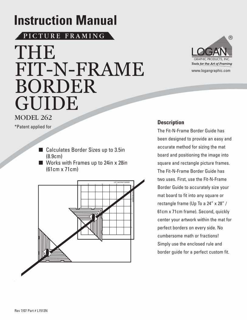
DescriptionThe Fit-N-Frame Border Guide has
been designed to provide an easy and
accurate method for sizing the mat
board and positioning the image into
square and rectangle picture frames.
The Fit-N-Frame Border Guide has
two uses. First, use the Fit-N-Frame
Border Guide to accurately size your
mat board to fit into any square or
rectangle frame (Up To a 24” x 28” /
61cm x 71cm frame). Second, quickly
center your artwork within the mat for
perfect borders on every side. No
cumbersome math or fractions!
Simply use the enclosed rule and
border guide for a perfect custom fit.
www.logangraphic.com
*Patent applied for
MODEL 262
Rev 7/07 Part # L1513N
� Calculates Border Sizes up to 3.5in(8.9cm)
� Works with Frames up to 24in x 28in(61cm x 71cm)
THE FIT-N-FRAME BORDER GUIDE M O D E L 2 6 2
Logan Graphic Products Inc., 1100 Brown Street, Wauconda, IL 60084 Toll Free 1 800 331 6232 www.logangraphic.com
www.logangraphic.com
Identification
1. Sizing Tool (Fig. 1)
a) Arm – Holds sliding alignment triangles
b) Alignment Triangles - Two alignment triangleswhich rotate on the sizing arm.Measurements are printed in 1/4” = 1/8”(6mm = 3mm) on the Border Grid scale.
c) Adjustment Knobs - Two adjustment knobs areused to tighten and loosen the adjustabletriangles, allowing them to slide alongthe rod.
2. Border Guide (Fig. 2) – white measurement gridand an alignment corner stop on the underside.
Fig. 1
Fig. 2
1
Logan Graphic Products Inc., 1100 Brown Street, Wauconda, IL 60084 Toll Free 1 800 331 6232 www.logangraphic.com
www.logangraphic.com
Instructions
THE FIT-N-FRAME BORDER GUIDE M O D E L 2 6 2
2
Sizing the Mat Board to the Frame
Step 1 - Loosen the adjustment knobs on both thealignment triangles and slide triangle A intothe lower left hand corner of the frame takingcare to make sure the edges of the alignmenttriangle fit snuggly into the corner of theframe. Tighten knob until secure (do not overtighten). (Fig. 3).
Step 2 - Slide Triangle B into the upper right handcorner of the frame making sure that it alsofits snuggly into place. Tighten knob untilsecure. (Fig. 4).
* All reference to measurements are approximate only.
A
B
Fig. 3
Fig. 4
A
B
THE FIT-N-FRAME BORDER GUIDE M O D E L 2 6 2
Logan Graphic Products Inc., 1100 Brown Street, Wauconda, IL 60084 Toll Free 1 800 331 6232 www.logangraphic.com
www.logangraphic.com
Instructions
3
Sizing the Mat Board to the Frame (continued)
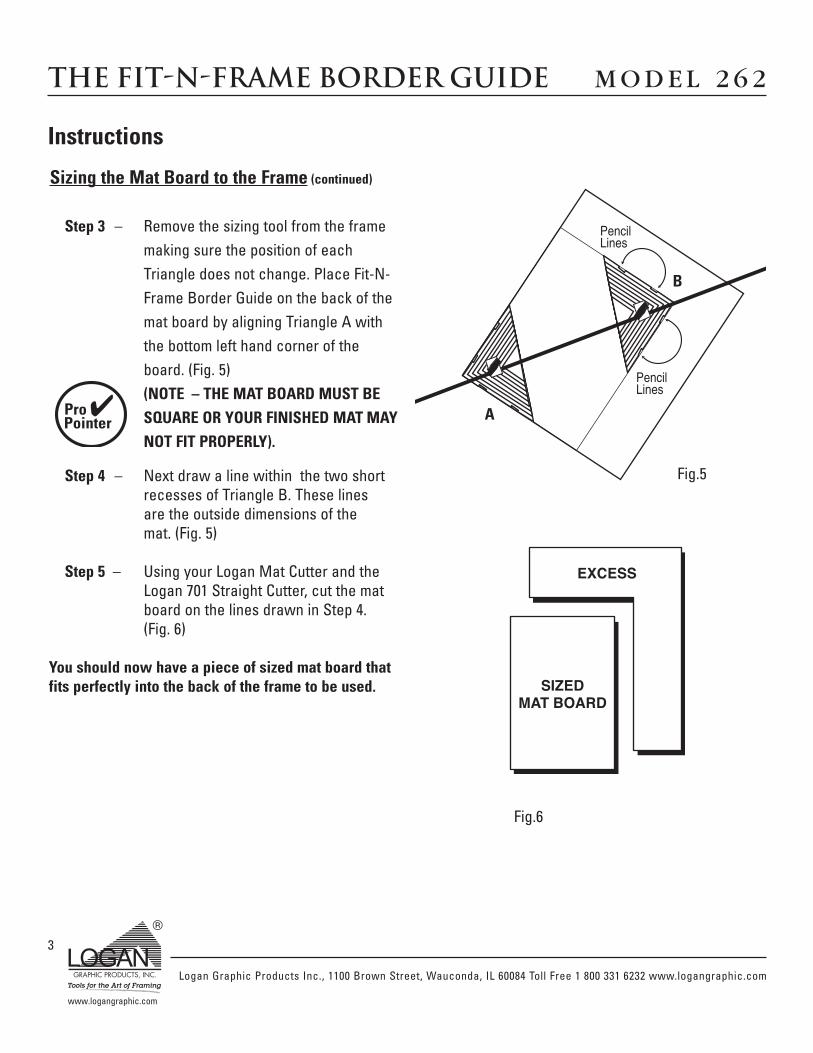
Step 3 – Remove the sizing tool from the framemaking sure the position of eachTriangle does not change. Place Fit-N-Frame Border Guide on the back of themat board by aligning Triangle A withthe bottom left hand corner of theboard. (Fig. 5)(NOTE – THE MAT BOARD MUST BESQUARE OR YOUR FINISHED MAT MAYNOT FIT PROPERLY).
Step 4 – Next draw a line within the two shortrecesses of Triangle B. These linesare the outside dimensions of themat. (Fig. 5)
Step 5 – Using your Logan Mat Cutter and theLogan 701 Straight Cutter, cut the matboard on the lines drawn in Step 4.(Fig. 6)
You should now have a piece of sized mat board thatfits perfectly into the back of the frame to be used.
✔
PencilLines
PencilLines
Fig.5
Fig.6
A
B
Logan Graphic Products Inc., 1100 Brown Street, Wauconda, IL 60084 Toll Free 1 800 331 6232 www.logangraphic.com
www.logangraphic.com
Instructions
THE FIT-N-FRAME BORDER GUIDE M O D E L 2 6 2
4
Centering the Image
Step 1 – Loosen the adjustment knobs on boththe alignment triangles and slideTriangle A into the lower left handcorner of the image to be framed andtighten knob. (Fig. 7)(* Note: You are working on the imagesurface so make sure that your handsand the tool are free of any dirt thatcould be deposited onto the image).
Step 2 – Slide Triangle B to the upper right handcorner of the image and tighten knob.Place both Triangles so that thecorners rest where you would like themat board to begin. Anything inside ofthe two Triangles will be exposed.
Step 3 – Working from the back of your matboard place the Border Guide in theupper right hand corner of the board.Border Guide has a built in 90 degreeedge that will locate the Border Guideonto the corner of the Mat Boardensuring accuracy. (Fig. 8)(*Note make sure that you areorienting the frame, board and imagein the same direction).
Fig.7
Fig.8
SIZEDMAT BOARD
✔
✔
THE FIT-N-FRAME BORDER GUIDE M O D E L 2 6 2
Logan Graphic Products Inc., 1100 Brown Street, Wauconda, IL 60084 Toll Free 1 800 331 6232 www.logangraphic.com
www.logangraphic.com
Instructions
5
Centering the Image (continued)
Step 4 – Place the Fit-N-Frame Border Guide onthe board and align Triangle A with thelower left hand corner. The upper rightTriangle B now rests on top of theBorder Grid.
Step 5 – For the left and right borders on yourmat board, trace the vertical edge ofTriangle B to the scale along the top ofthe Border Guide. Write down thismeasurement. (Fig.9)
Step 6 – For the top and bottom borders tracethe horizontal edge of Triangle B to thescale on the right side of the BorderGuide. Write down this measurement.*Note the scale on the Border Guideis 1”=1/2”. Simply read the scalemeasurements as they are indicatedon the Border Guide. (Fig. 10)
Step 7 – Set up your Logan Mat Cutter to themeasurements recorded. First cut theleft and right borders. Re-set the matcutter to the second measurement (top& bottom ) and cut the top and bottomborders.
Congratulations! Your mat board should now fitperfectly into your frame and the opening for theimage should be perfectly centered in the picture.
Fig.9
Fig.10
2 12 1112233 3 2 2 2 2 1 1 1 1 0
0
1
1
1
1
2
22
2
2
2
1
1
1
1
58
38
18
38
58
78
3 3
2
2
3
12 1
438
18
78
34
58
12
38
14
18
78
58
38
34
12 1
434
78
12 1
4
18
14
12
34
38
58
78
18
14
12
34
38
58
78
18
14
12
34
18
TOP
&B
OTTO
MB
OR
DER
LEFT & RIGHT BORDER
Example:1 1/2" Left & Right X 1 1/4" Top & Bottom
(3.8cm Left & Right X 3.2cm Top & Bottom)
A
B
Logan Graphic Products Inc., 1100 Brown Street, Wauconda, IL 60084 Toll Free 1 800 331 6232 www.logangraphic.com
www.logangraphic.com
THE FIT-N-FRAME BORDER GUIDE M O D E L 2 6 2
6
Helpful Hints and Extras
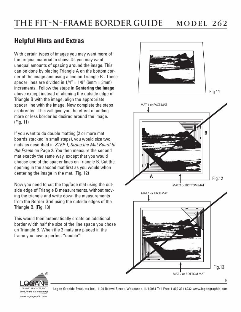
With certain types of images you may want more ofthe original material to show. Or, you may wantunequal amounts of spacing around the image. Thiscan be done by placing Triangle A on the bottom cor-ner of the image and using a line on Triangle B . Thesespacer lines are divided in 1/4” = 1/8” (6mm = 3mm)increments. Follow the steps in Centering the Imageabove except instead of aligning the outside edge ofTriangle B with the image, align the appropriatespacer line with the image. Now complete the stepsas directed. This will give you the effect of addingmore or less border as desired around the image.(Fig. 11)
If you want to do double matting (2 or more matboards stacked in small steps), you would size twomats as described in STEP 1, Sizing the Mat Board tothe Frame on Page 2. You then measure the secondmat exactly the same way, except that you wouldchoose one of the spacer lines on Triangle B. Cut theopening in the second mat first as you would whencentering the image in the mat. (Fig. 12)
Now you need to cut the top/face mat using the out-side edge of Triangle B measurements, without mov-ing the triangle and write down the measurementsfrom the Border Grid using the outside edges of theTriangle B. (Fig. 13)
This would then automatically create an additionalborder width half the size of the line space you choseon Triangle B. When the 2 mats are placed in theframe you have a perfect “double”!
Fig.11
Fig.12
Fig.13
A
B
Logan Graphic Products Inc., 1100 Brown Street, Wauconda, IL 60084 Toll Free 1 800 331 6232 www.logangraphic.com
www.logangraphic.com
Logan Graphic Products, Inc. (“Logan”) warrants the Fit-N-Frame Border Guide, to be free from defects in parts and workmanship for a period of one year from the date of original
purchase. Logan warrants that it will either repair or replace, at it’s sole discretion, any necessary replacement parts found to be defective. Should the product need to be returned to
Logan for repair or replacement parts, authorization for any return must come from Logan in writing. Costs of returning the product to Logan, including insurances, shall be borne by the
purchaser. Logan shall not be liable for any damages or losses, incidental or consequential, direct or indirect, arising from the use of this product. This warranty extends only to the
original purchaser and is not assignable or transferable. This warranty is in lieu of all other warranties, expressed or implied.
Warranty
For more creative ideas in matting,pick up a copy of Logan’s “How To Cut Mats” DVD by VivianC. Kistler, CPF. - Model 237-D .
Complete and detailed directions featuringLogan's Picture Framing Tools System. Learninside secrets from professional framers for cre-ating your own custom framed art.
Home Picture Framing - Model F245
Also available are 3 different books on matting andframing also by Vivian C. Kistler, CPF.
Basic Mat Cutting - Model 238.Mat Decoration Book- Model 240.Do It Yourself Picture Framing- Model 241.
3-Step Oval and Circle Mat Cutter is easy to use,fast and portable. Cuts ovals or circles on the sur-face of the matboard using a patented 3-step mech-anism for gradual increase of blade depth.
Converts from oval to circle cutter with a turn of aknob. 3-Step Oval & Circle Mat Cutter - Model 201.Replacement blades - Model 324.
Simplex V-Groover offers a way to cut surface V-Grooves quickly and accurately with zero overcuts.
Push-Pull action cuts V-Grooves right on the surfaceof the matboard eliminating any need for trimming ortaping. Works entirely with stops.
Simplex V-Groover - Model 703.
Replacement Blades - Model 1258.
See your local Logan Dealer for availability or pleasecheck our 'where to buy' section on Logan's websitewww.logangraphic.com. Call at 800/331-6232 fora dealer near you.
Also available from Logan…
301-S CCompact Includes bevel and straight cutting heads andfive extra blades. Features a 32” Board mounted mat cutting system with parallel mat guide, guide rail, straight and bevel cutting heads and creative matting instructions. PlusFREE set up and instruction DVD. Replacement blade #270
450 IINTERMEDIATE ++40” Board mounted mat cutting system withparallel mat guide, improved 90 degree squaringbar, colored board surface, improved guide railwith production stop and straight and bevel cutting heads. Includes creativematting instructions and includes five extra blades. Plus FREE set up and instruction DVD. Replacement blade #270.
Mode d'emploiE N C A D R E M E N T
DescriptionLe guide-bordure Fit-N-Frame a été conçu pour offrir une méth-ode facile et précise de mesurer le passe-partout et de position-ner l’image dans des cadres carrés et rectangulaires. Le guide-bordure Fit-N-Frame satisfait deux besoins. Primo, le guide-bor-dure Fit-N-Frame permet de mesurer précisément votre passe-partout afin qu’il s’adapte à n’importe quel cadre carré ou rec-tangulaire (dimensions maximales : 24 po x 28 po). Secondo, ilvous permet de centrer rapidement votre document sur le passe-partout et d’obtenir des bordures parfaites. Nul besoin de calculssavants ! Utilisez simplement la règle et le guide-bordure incluspour une adaptation sur-mesure parfaite.
www.logangraphic.com
*Brevet en instanceMODELE 262
GUIDE-BORDURE FIT-N-FRAME
AnleitungR A H M U N G
FIT-N-FRAME BORDER GUIDE
BeschreibungMit dem Fit-N-Frame Border Guide können Passepartoutkartonseinfach und genau abgemessen und Bilder in quadratischenoder rechteckigen Bilderrahmen positioniert werden. Der Fit-N-Frame Border Guide wird auf zwei Arten eingesetzt. Messen Siezunächst anhand des Fit-N-Frame Border Guide denPassepartoutkarton entsprechend Ihrem quadratischen oderrechteckigen Rahmen ab (Rahmengröße bis max. 60 x 70 cm).Wenn Sie dann das Bild auf dem Passepartoutkarton zentrieren,stimmt die Randgröße auf allen Seiten. Sie sparen sichGleichungen und Bruchrechnung! Um den Karton genauabzumessen, verwenden Sie einfach die beigefügteFührungsstange und die Randschablone.
*Patent beantragtMODELL 262
Manuale d’usoI N C O R N I C I A T U R A
DescrizioneLa guida per bordi Fit-N-Frame è stata studiata per essere unmetodo semplice ma preciso per dimensionare il cartoncino eposizionare la fotografia in cornici quadrate o rettangolari. Laguida per bordi Fit-N-Frame ha due applicazioni. Per prima cosa,utilizzate la guida Fit-N-Frame per dimensionare con precisione ilcartoncino da inserire in una cornice quadrata o rettangolare(cornici fino a 24” x 28”). Quindi, centrate la vostra immagine nelcartoncino per avere bordi perfetti su ogni lato. Niente calcoli ofrazioni complicate! È sufficiente utilizzare il righello incluso e laguida per bordi per avere un cartoncino delle dimensionidesiderate.
*In attesa di brevettoMODELLO 262
LA GUIDA PER BORDI FIT-N-FRAME
Manual de instruccionesE N M A R C A D O D E C UA D R O S
GUÍADE BORDES PARA MONTAJEEN BASTIDOR GUIDEDescriptionLe guide-bordure Fit-N-Frame a été conçu pour offrir une méth-ode facile et précise de mesurer le passe-partout et de position-ner l’image dans des cadres carrés et rectangulaires. Le guide-bordure Fit-N-Frame satisfait deux besoins. Primo, le guide-bor-dure Fit-N-Frame permet de mesurer précisément votre passe-partout afin qu’il s’adapte à n’importe quel cadre carré ou rec-tangulaire (dimensions maximales : 24 po x 28 po). Secondo, ilvous permet de centrer rapidement votre document sur le passe-partout et d’obtenir des bordures parfaites. Nul besoin de calculssavants ! Utilisez simplement la règle et le guide-bordure incluspour une adaptation sur-mesure parfaite.
*Patente utilizada paraMODELO 262
FR GR
ITL ESP
Logan Graphic Products Inc., 1100 Brown Street, Wauconda, IL 60084 Toll Free 1 800 331 6232 www.logangraphic.com
www.logangraphic.com
FIT-N-FRAME BORDER GUIDE MODELL 262
LA GUIDA PER BORDI FIT-N-FRAME MODELLO 262 GUÍA DE BORDES PARA MONTAJE EN BASTIDOR MODELO 262
GUIDE-BORDURE FIT-N-FRAME MODELE 262
1. Outil de dimensionnement (Fig. 1)
a) Bras – maintient les triangles d’aligne-ment coulissants.
b) Triangles d’alignement – deux trianglesd’alignement qui pivotent sur le bras dedimensionnement.
Les mesures sont imprimées à l’échelle 1/4po = 1/8 po sur le gabarit de bordure.
c) Molettes de réglage – deux molettes deréglage permettent de serrer et dedesserrer les triangles d’alignementpour qu’ils puissent coulisser sur latige.
2. Guide-bordure (Fig. 2) – grille demesure blanche avec espacements deslignes de 1/16 po et butée d’alignementde coin au verso.
Fig. 1
Fig. 2
1
1. Messwerkzeug (Abb. 1)
a) Stange - Hält die beweglichenAusrichtungsdreiecke
b) Ausrichtungsdreiecke - Zwei auf derMessstange drehbareAusrichtungsdreiecke
Die Randschablone ist in einem Maßstabvon 1 : 2 (1/4” = 1/8”) bedruckt.
c) Einstellknöpfe - Anhand der beidenEinstellknöpfen werden dieAusrichtungsdreiecke festgezogen bzw.gelöst, sodass sie auf der Stange ver-schoben werden können.
2. Randschablone (Abb. 2) - Ein weißesRaster mit parallelen Linien im Abstandvon 1/16" (Zoll) sowie einAnschlagpunkt für die Eckeinstellungauf der Unterseite.
1. Attrezzo per dimensionare (Fig. 1)
a) Braccio: fissa i triangoli scorrevoli diallineamento
b) Triangoli di allineamento: due triangolidi allineamento che ruotano sul braccioper il dimensionamento.
Le misure sono stampate in 1/4” = 1/8” sulrighello della griglia per bordi.
c) Manopole di regolazione: le duemanopole di regolazione servono perserrare e allentare la posizione dei tri-angoli per farli scorrere lungo l’asta.
2. Guida per bordi (Fig. 2): griglia di mis-urazione bianca con linee distanziate inmultipli di 1/16” e un fermo angolare diallineamento sul lato inferiore.
1. Herramienta de medición (Fig. 1)
a) Brazo: sostiene triángulos de alin-eación deslizables.
b) Triángulos de alineación: dos triángulosde alineación que rotan en el brazo demedición.
Las medidas están impresas en la escala dela cuadrícula de bordes en 1/4” = 1/8”.
c) Botones de ajuste: se utilizan dosbotones de ajuste para tensar y aflojarlos triángulos de ajuste permitiendoque se deslicen por la varilla.
2. Guía de bordes (Fig. 2): grilla de mediciónen blanco con líneas espaciadas queaumenta de a 1/16" y un tope de alin-eación en la esquina sobre la parteinferior.
Identification Beschreibung
Identificazione Identificación
FR GR
ITL ESP
Logan Graphic Products Inc., 1100 Brown Street, Wauconda, IL 60084 Toll Free 1 800 331 6232 www.logangraphic.com
www.logangraphic.com
FIT-N-FRAME BORDER GUIDE MODELL 262
GUÍA DE BORDES PARA MONTAJE EN BASTIDOR MODELO 262LA GUIDA PER BORDI FIT-N-FRAME MODELLO 262
GUIDE-BORDURE FIT-N-FRAME MODELE 262
2
A
B
Fig. 3
Fig. 4
Dimensionnement du passe-partout enfonction du cadre
Étape 1 – Desserrez les molettes de réglagedes deux triangles d’alignement et glissez letriangle A dans l’angle inférieur gauche ducadre en prenant soin que les bords du tri-angle d’alignement s’adaptent bien dansl’angle du cadre. Serrez fermement lamolette (mais sans excès). (Fig. 3).
Étape 2 – Glissez le triangle B dans l’anglesupérieur droit du cadre en s’assurant qu’ilse loge bien en place. Serrez fermement lamolette. (Fig. 4).
Zuschneiden des Passepartoutkartonsentsprechend der Rahmengröße
Schritt 1 - Lösen Sie die Einstellknöpfe aufbeiden Ausrichtungsdreiecken und schiebenSie Dreieck A in die untere rechte Ecke desRahmens. Achten Sie dabei darauf, dass dieKanten des Dreiecks ganz in dieRahmenecke geschoben werden. Ziehen Sieden Knopf fest (nicht überziehen). (Abb. 3)
Schritt 2 - Schieben Sie Dreieck B in dieobere rechte Ecke des Rahmens. Achten Sieauch hier darauf, dass die Kanten ganz indie Rahmenecke geschoben werden. ZiehenSie den Knopf fest. (Abb. 4)
Come dimensionare il cartoncino per lacornice
Procedura 1 – allentare le manopole di rego-lazione sui due triangoli di allineamento e farscorrere il triangolo A verso l’angolo inferi-ore sinistro della cornice facendo attenzioneche i bordi del triangolo coincidano perfetta-mente con l’angolo della cornice. Serrare lamanopola perché tenga (non serrarla ecces-sivamente) (Fig. 3).
Procedura 2 – far scorrere il triangolo B nel-l’angolo superiore destro della cornicefacendo attenzione che anch’esso coincidacon l’angolo. Serrare la manopola perchétenga (Fig. 4).
Cómo medir el panel con el marco
Paso 1: afloje los botones de ajuste enambos triángulos de alineación y deslice elTriángulo A hacia la esquina inferior izquier-da del marco cuidando que los bordes deltriángulo de alineación se ajusten perfecta-mente a la esquina del marco. Ajuste elbotón hasta que quede firme, sin excederse.(Fig. 3).
Paso 2: deslice el triángulo B hasta laesquina superior derecha del marco asegu-rando que también se ajuste perfectamenteen el lugar. Ajuste el botón hasta que quedefirme. (Fig. 4).
Instructions Anleitung
Istruzioni Instrucciones
FR GR
ITL ESP
Logan Graphic Products Inc., 1100 Brown Street, Wauconda, IL 60084 Toll Free 1 800 331 6232 www.logangraphic.com
www.logangraphic.com
FIT-N-FRAME BORDER GUIDE MODELL 262
LA GUIDA PER BORDI FIT-N-FRAME MODELLO 262 GUÍA DE BORDES PARA MONTAJE EN BASTIDOR MODELO 262
GUIDE-BORDURE FIT-N-FRAME MODELE 262
3
Dimensionnement du passe-partouten(suite)
Étape 3 – Retirez l'outil de dimensionnementdu cadre et assurez-vous que la position dechaque triangle n’a pas changée. Placez leguide-bordure Fit-N-Frame au dos du passe-partout en alignant le triangle A sur l'angleinférieur gauche du passe-partout. (Fig. 5)
(REMARQUE : LE PASSE-PARTOUT DOIT ÊTRE ÀL’ÉQUERRE, SINON IL RISQUEDE NE PAS S'ADAPTER COR-RECTEMENT).
Étape 4 – Tracez ensuite une ligne à l'in-térieur des deux petits renfoncements dutriangle B. Ces lignes constituent les dimen-sions extérieures du passe-partout. (Fig. 5)
Étape 5 – À l’aide du couteau à passe-partout Logan et du couteau droit à passe-partout Logan 701, coupez le passe-partoutle long des lignes tracées à l’étape 4. (Fig. 6)
Vous devriez avoir maintenant un passe-partout sur mesure qui s’adapte parfaite-ment au dos du cadre à utiliser.
✔ PencilLines
PencilLines
Fig.5
Fig.6
Zuschneiden des Passepartoutkartonsentsprechend der Rahmengröße(Fortsetzung)
Schritt 3 - Nehmen Sie das Messwerkzeugvom Rahmen und achten Sie dabei darauf,dass die Dreiecke nicht verrutschen. LegenSie den Fit-N-Frame Border Guide auf dieRückseite des Passepartoutkartons, indemSie Dreieck A auf die untere linke Ecke desKartons auflegen. (Abb. 5)
(HINWEIS - DER PASSEPA-RTOUTKARTON MUSSRECHTECKIG SEIN, DASONST DER AUSGESCHNIT-TENE KARTON EVENTUELLNICHT KORREKT PASST.)
Schritt 4 - Ziehen Sie jetzt eine Linie inden beiden flachen Aussparungen vonDreieck B. Diese Linien sind die Außenkantedes Passepartouts. (Abb. 5)
Schritt 5 - Schneiden Sie mit dem LoganMat Cutter und Logan 701 Straight Cutterden Passepartoutkarton auf den in Schritt 4aufgezeichneten Linien. (Abb. 6)
Sie sollten jetzt einen Passepartoutkartonhaben, der genau in den zu verwendendenRahmen passt. utiliser.
✔
Come dimensionare il cartoncino per lacornice (continua)
Procedura 3 - rimuovere l’attrezzo perdimensionare dalla cornice controllandoche la posizione dei due triangoli non cambi.Posizionare la guida per bordi Fit-N-Framesul retro del cartoncino allineando il trian-golo A con l’angolo inferiore sinistro delcartoncino (Fig. 5).
(NOTA: IL CARTONCINO DEVEESSERE SQUADRATOPERCHÉ IN CASO CON-TRARIO IL CARTONCINOFINITO NON SI ADAT-
TEREBBE CORRETTAMENTE ALLACORNICE).
Procedura 4 - tracciare una riga all’internodei due incavi del triangolo B. Queste righeindicano le dimensioni esterne del cartonci-no (Fig. 5).
Procedura 5 – con la taglierina per passep-artout Logan e la taglierina per tagli dirittiLogan 701, tagliare il cartoncino in cor-rispondenza delle righe tracciate nella pro-cedura 4 (Fig. 6).
Ne risulta un cartoncino di dimensioni chesi adattano perfettamente al retro della cor-nice da montare.
✔
Cómo medir los bordes del panel con elmarco (continuación)
Paso 3: retire la herramienta de medicióndel marco asegurándose de que la posiciónde cada triángulo no cambie. Coloque laGuía de bordes para montaje en bastidor enla parte posterior del panel al alinear elTriángulo A con la esquina inferior izquierdadel panel. (Fig. 5)
(NOTA: EL PANEL DEBE SERCUADRADO O EL DISEÑOTERMINADO NO SEAJUSTARÁ CORRECTA-MENTE).
Paso 4: luego dibuje una línea dentro de lasdos ranuras del Triángulo B. Estas líneasestán fuera de las dimensiones del panel.(Fig. 5)
Paso 5: con el cortador de placas Logan y elcortador recto Logan 701, corte el panel porlas líneas dibujadas en el paso 4. (Fig. 6)
Ahora tendrá una parte del panel medidaque se ajusta perfectamente a la parte pos-terior del marco que se utilizará.
✔
Instructions Anleitung
Istruzioni Instrucciones
FR GR
ITL ESP
Logan Graphic Products Inc., 1100 Brown Street, Wauconda, IL 60084 Toll Free 1 800 331 6232 www.logangraphic.com
www.logangraphic.com
FIT-N-FRAME BORDER GUIDE MODELL 262
GUÍA DE BORDES PARA MONTAJE EN BASTIDOR MODELO 262LA GUIDA PER BORDI FIT-N-FRAME MODELLO 262
GUIDE-BORDURE FIT-N-FRAME MODELE 262
4
Fig.7
Fig.8
SIZEDMAT BOARD
Centrage de l’image
Étape 1 – Desserrez les molettes de réglagedes deux triangles d’alignement et glissez letriangle A dans l’angle inférieur gauche del'image à encadrer, puis serrez la molette.
(Fig. 7)
(*REMARQUE : VOUS TRA-VAILLEZ SUR LA SURFACE DEL’IMAGE ; ASSUREZ-VOUSQUE VOS MAINS ET L'OUTILSONT EXEMPTS DE SALETÉS
QUI POURRAIENT SE DÉPOSER SUR L’IM-AGE).
Étape 2 – Glissez le triangle B dans l’anglesupérieur droit de l'image et serrez lamolette. Placez les deux triangles demanière à ce que les angles soient situés àl’endroit précis où le passe-partout doitcommencer. Tout ce qui est à l’intérieur desdeux triangles sera exposé. (Fig. 8)
Étape 3 – Depuis le dos du passe-partout,placez le guide-bordure dans l’anglesupérieur droit du passe-partout. Le guide-bordure comporte un bord à 90° intégré per-mettant de positionner précisément leguide-bordure dans l'angle du passe-partout.
(*REMARQUE : VEILLEZ ÀORIENTER LE CADRE, LEPASSE-PARTOUT ET
L’IMAGE DANS LA MÊMEDIRECTION).
✔
✔
Zentrieren des Bildes Schritt 1 - Lösen Sie die Einstellknöpfe anbeiden Ausrichtungsdreiecken, schieben SieDreieck A in die linke untere Ecke des zurahmenden Bildes und ziehen Sie den Knopffest. (Abb. 7)
(* HINWEIS: DA SIE AUF DERBILDOBERFLÄCHE ARBEIT-EN, SOLLTEN SIE DARAUFACHTEN, DASS HÄNDE UNDWERKZEUG FREI VON
SCHMUTZ SIND, DER AUF DAS BILDGELANGEN KÖNNTE.)
Schritt 2 - Schieben Sie Dreieck B in dieobere rechte Ecke des Bildes und ziehen Sieden Knopf fest. Legen Sie beide Dreiecke so,dass die Ecken dort aufliegen, wo dasPassepartout beginnen soll. Die gesamteFläche innerhalb der beiden Dreiecke wirdsichtbar sein. (Abb. 8)
Schritt 3 - Arbeiten Sie von der Rückseitedes Passepartoutkartons aus und legen Siedie Randschablone in die obere rechte Eckedes Kartons. Die rechtwinklige Kante derRandschablone passt sich der Ecke desPassepartoutkartons an und gewährleistetso die Genauigkeit der Messung.
(*HINWEIS: ACHTEN SIEDARAUF, DASS SIE DENRAHMEN, DEN KARTON UNDDAS BILD IN DERSELBENRICHTUNG AUSRICHTEN.)
✔
✔
Come centrare la fotografiaProcedura 1- allentare le manopole di rego-lazione su entrambi i triangoli di allineamen-to e far scorrere il triangolo A nell’angoloinferiore sinistro della fotografia da incorni-ciare, quindi serrare la manopola (Fig. 7).
(*NOTA: DATO CHE SI LAVO-RA SULLA SUPERFICIE DELLAFOTOGRAFIA, ASSICURARSICHE LE MANI E GLI ATTREZZI
SIANO PULITI PER EVITARE CHE LAFOTOGRAFIA SI SPORCHI). Procedura 2 - far scorrere il triangolo B nel-l’angolo superiore destro della fotografia eserrare la manopola. Posizionare i due trian-goli in modo che gli angoli appoggino nelpunto in cui si desidera inizi il bordo del car-toncino. La parte interna ai due triangolirisulterà esposta (Fig. 8).Procedura 3 - sul retro del cartoncino,posizionare la guida per bordi nell’angolosuperiore destro del cartoncino. La guidaper bordi presenta un angolo di 90° che con-sente di posizionarla sull’angolo del carton-cino per ottenere la massima precisione. (*NOTA: ASSICURARSI DI ORIENTARE LACORNICE, IL CARTONCINO E LAFOTOGRAFIA NELLA STESSA DIREZIONE).
✔
Cómo centrar la imagen
Paso 1: afloje los botones de ajuste enambos triángulos de alineación y deslice elTriángulo A hacia la esquina inferior izquier-da de la imagen que se enmarcará y ajusteel botón. (Fig. 7)
(* NOTA: ESTÁ TRABAJANDOEN LA SUPERFICIE DE LAIMAGEN, POR LO TANTO,ASEGÚRESE DE QUE SUSMANOS Y LA HERRAMIENTA
ESTÉN LIMPIAS Y PUEDAN APOYARSESOBRE LA IMAGEN).
Paso 2: deslice el Triángulo B hacia laesquina superior derecha de la imagen yajuste el botón. Coloque ambos triángulosde manera que las esquinas se apoyen en ellugar en que le gustaría que comience elpanel. Todo lo que esté dentro de los dostriángulos quedará al descubierto. (Fig. 8)
Paso 3: en la parte posterior del panel,coloque la Guía de bordes en la esquinasuperior derecha del panel. La Guía de bor-des se construyó con un borde a 90 gradosque ubicará la Guía de bordes en la esquinadel panel para asegurar su precisión.
(*TENGA EN CUENTA UBICAR EL MARCO,EL PANEL Y LA IMAGEN EN LA MISMADIRECCIÓN).
✔
Instructions Anleitung
Istruzioni Instrucciones
FR GR
ITL ESP
Logan Graphic Products Inc., 1100 Brown Street, Wauconda, IL 60084 Toll Free 1 800 331 6232 www.logangraphic.com
www.logangraphic.com
FIT-N-FRAME BORDER GUIDE MODELL 262
LA GUIDA PER BORDI FIT-N-FRAME MODELLO 262 GUÍA DE BORDES PARA MONTAJE EN BASTIDOR MODELO 262
GUIDE-BORDURE FIT-N-FRAME MODELE 262
5
Centrage de l’image (suite)
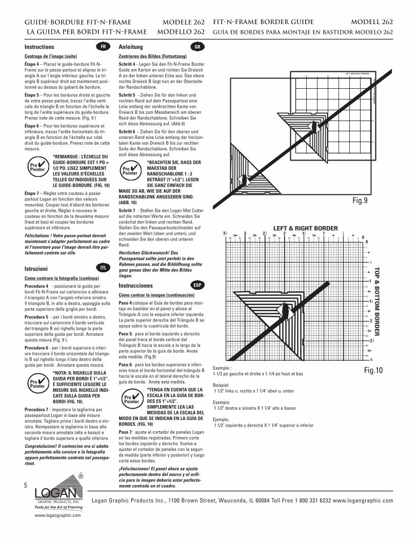
Étape 4 – Placez le guide-bordure Fit-N-Frame sur le passe-partout et alignez le tri-angle A sur l'angle inférieur gauche. Le tri-angle B supérieur droit est maintenant posi-tionné au dessus du gabarit de bordure.
Étape 5 – Pour les bordures droite et gauchede votre passe-partout, tracez l’arête verti-cale du triangle B en fonction de l’échelle lelong de l’arête supérieure du guide-bordure.Prenez note de cette mesure. (Fig. 9 )
Étape 6 – Pour les bordures supérieure etinférieure, tracez l’arête horizontale du tri-angle B en fonction de l’échelle sur côtédroit du guide-bordure. Prenez note de cettemesure.
*REMARQUE : L’ÉCHELLE DUGUIDE-BORDURE EST 1 PO =1/2 PO. LISEZ SIMPLEMENTLES VALEURS D'ÉCHELLESTELLES QU'INDIQUÉES SURLE GUIDE-BORDURE. (FIG. 10)
Étape 7 – Réglez votre couteau à passe-partout Logan en fonction des valeursmesurées. Coupez tout d’abord les borduresgauche et droite. Réglez à nouveau lecouteau en fonction de la deuxième mesure(haut et bas) et coupez les borduressupérieure et inférieure.
Félicitations ! Votre passe-partout devraitmaintenant s’adapter parfaitement au cadreet l'ouverture pour l'image devrait être par-faitement centrée sur elle.
Fig.9
Fig.10
2 12 1112233 3 2 2 2 2 1 1 1 1 0
0
1
1
1
1
2
22
2
2
2
1
1
1
1
58
38
18
38
58
78
3 3
2
2
3
12 1
438
18
78
34
58
12
38
14
18
78
58
38
34
12 1
434
78
12 1
4
18
14
12
34
38
58
78
18
14
12
34
38
58
78
18
14
12
34
18
TOP
& BOTTO
M BORDER
LEFT & RIGHT BORDER
Exemple :1-1/2 po gauche et droite x 1-1/4 po haut et bas
Beispiel:1 1/2" links u. rechts x 1 1/4" oben u. unten
Esempio:1 1/2" destra e sinistra X 1 1/4" alto e basso
Ejemplo:1 1/2" izquierda y derecha X 1 1/4" superior e inferior
✔
Zentrieren des Bildes (Fortsetzung)
Schritt 4 - Legen Sie den Fit-N-Frame BorderGuide am Karton an und richten Sie DreieckA an der linken unteren Ecke aus. Das obererechte Dreieck B liegt nun an der Oberseiteder Randschablone.
Schritt 5 - Ziehen Sie für den linken undrechten Rand auf dem Passepartout eineLinie entlang der senkrechten Kante vonDreieck B bis zum Messbereich am oberenRand der Randschablone. Schreiben Siesich diese Abmessung auf. (Abb.9)
Schritt 6 - Ziehen Sie für den oberen undunteren Rand eine Linie entlang der horizon-talen Kante von Dreieck B bis zur rechtenSeite der Randschablone. Schreiben Siesich diese Abmessung auf.
*BEACHTEN SIE, DASS DERMAßSTAB DERRANDSCHABLONE 1 : 2BETRÄGT (1”=1/2”). LESENSIE GANZ EINFACH DIE
MAßE SO AB, WIE SIE AUF DERRANDSCHABLONE ANGEGEBEN SIND.(ABB. 10)
Schritt 7 - Stellen Sie den Logan Mat Cutterauf die notierten Werte ein. Schneiden Siezunächst den linken und rechten Rand.Stellen Sie den Passepartoutschneider aufden zweiten Wert (oben und unten), undschneiden Sie den oberen und unterenRand.
Herzlichen Glückwunsch! DasPassepartout sollte jetzt perfekt in denRahmen passen, und die Bildöffnung sollteganz genau über der Mitte des Bildesliegen.
✔
Come centrare la fotografia (continua)
Procedura 4 - posizionare la guida perbordi Fit-N-Frame sul cartoncino e allineareil triangolo A con l’angolo inferiore sinistro.Il triangolo B, in alto a destra, appoggia sullaparte superiore della griglia per bordi.
Procedura 5 - per i bordi sinistro e destro,tracciare sul cartoncino il bordo verticaledel triangolo B sul righello lungo la partesuperiore della guida per bordi. Annotarequesta misura (Fig. 9 ).
Procedura 6 - per i bordi superiore e inferi-ore tracciare il bordo orizzontale del triango-lo B sul righello lungo il lato destro dellaguida per bordi. Annotare questa misura.
*NOTA: IL RIGHELLO SULLAGUIDA PER BORDI È 1”=1/2”.È SUFFICIENTE LEGGERE LEMISURE SUL RIGHELLO INDI-CATE SULLA GUIDA PERBORDI (FIG. 10).
Procedura 7 - impostare la taglierina perpassepartout Logan in base alle misureannotate. Tagliare prima i bordi destro e sin-istro. Reimpostare la taglierina in base allaseconda misura annotata (alto e basso) etagliare il bordo superiore e quello inferiore.
Congratulazioni! Il cartoncino ora si adattaperfettamente alla cornice e la fotografiaappare perfettamente centrata nel passepa-rtout.
✔
Cómo centrar la imagen (continuación)
Paso 4:coloque el Guía de bordes para mon-taje en bastidor en el panel y alinee elTriángulo A con la esquina inferior izquierda.La parte superior derecha del Triángulo B seapoya sobre la cuadrícula del borde.
Paso 5: para el borde izquierdo y derechodel panel trace el borde vertical delTriángulo B hacia la escala a lo largo de laparte superior de la guía de borde. Anoteesta medida. (Fig.9)
Paso 6: para los bordes superiores e inferi-ores trace el borde horizontal del triángulo Bhacia la escala en el lateral derecho de laguía de borde. Anote esta medida.
*TENGA EN CUENTA QUE LAESCALA EN LA GUÍA DE BOR-DES ES 1”=1/2”.SIMPLEMENTE LEA LASMEDIDAS DE LA ESCALA DEL
MODO EN QUE SE INDICAN EN LA GUÍA DEBORDES. (FIG. 10)
Paso 7: ajuste el cortador de paneles Loganen las medidas registradas. Primero cortelos bordes izquierdo y derecho. Vuelva aajustar el cortador de paneles con la segun-da medida (parte inferior y posterior) y luegocorte estos bordes.
¡Felicitaciones! El panel ahora se ajustaperfectamente dentro del marco y el orifi-cio para la imagen debería estar perfecta-mente centrado en el cuadro.
✔
Instructions Anleitung
Istruzioni
Instrucciones
FR GR
ITL
ESP
Logan Graphic Products Inc., 1100 Brown Street, Wauconda, IL 60084 Toll Free 1 800 331 6232 www.logangraphic.com
www.logangraphic.com
FIT-N-FRAME BORDER GUIDE MODELL 262
GUÍA DE BORDES PARA MONTAJE EN BASTIDOR MODELO 262LA GUIDA PER BORDI FIT-N-FRAME MODELLO 262
GUIDE-BORDURE FIT-N-FRAME MODELE 262
6
Conseils utiles et extrasIl peut être préférable de montrer davantage dumatériau original avec certains types d’images. Ouvous pouvez souhaiter des espaces inégaux autourde l'image. Ceci est réalisable en plaçant le triangleA dans l'angle inférieur de l'image et en utilisantune ligne du triangle B. L’espacement de ces lignesest à l’échelle 1/4 po = incréments de 1/8 po.Reprenez les étapes de la section Centrage de l’im-age ci-dessus, mais au lieu d’aligner l’arêteextérieure du triangle B avec l’image, alignez laligne d’espacement appropriée avec l’image.Réalisez maintenant les étapes comme indiqué.Cette méthode vous permet de moduler l'épaisseurde la bordure autour de l'image selon votre goût.(Fig. 11)
Si vous souhaitez un double passe-partout (2 ouplusieurs passe-partout empilés par petites étapes): Dimensionnez deux passe-partout comme décrit àl’étape 1, Dimensionnement du passe-partout enfonction du cadre, page 2. Mesurez ensuite le deux-ième passe-partout de la même façon, exceptionfaite que vous choisirez l'une des lignes d'espace-ment du triangle B. Découpez tout d’abord l'ouver-ture du deuxième passe-partout comme vous leferiez pour centrer l’image dans le passe-partout.(Fig. 12)
Découpez ensuite le passe-partout supérieur enutilisant le bord extérieur du triangle B, sans bougerle triangle, puis prenez note des mesures du gabaritde bordure en utilisant les bords extérieurs du trian-gle B. (Fig. 13)
Ceci a pour effet de créer automatiquement unebordure supplémentaire d’une épaisseur égale à lamoitié de la ligne d’espacement choisie pour le tri-angle B. Lorsque les deux passe-partout sontplacés dans le cadre, vous obtenez alors un « dou-ble » parfait !
Fig.11
Fig.12
Fig.13
Nützliche TippsBei bestimmten Bildtypen ist es ratsam, etwas mehrMaterial sichtbar zu lassen. Alternativ kann auchum das Bild herum verschieden viel Platz gelassenwerden. Legen Sie dazu Dreieck A an der unterenEcke des Bildes an und ziehen Sie eine Linie zuDreieck B. Die Linien liegen im Abstand von 1/4” =1/8” zueinander. Befolgen Sie die Schritte unter„Zentrieren des Bildes“, statt jedoch dieAußenkante von Dreieck B am Bild auszurichten,richten Sie die entsprechende Abstandslinie amBild aus. Führen Sie jetzt die Schritte wievorgegeben aus. Auf diese Weise erhalten Sie jenach Wunsch mehr oder weniger Rand um das Bild.(Abb. 11)
Wenn Sie ein doppeltes Passepartout möchten(zwei oder mehr leicht abgestuftePassepartoutkartons übereinander), messen Siezwei Kartons, wie in Schritt 1 „Abmessen desPassepartoutkartons“ auf Seite 2 beschrieben, aus.Messen Sie dann den zweiten Karton auf dieselbeArt und Weise, aber wählen Sie eine derAbstandslinien auf Dreieck B aus. Schneiden Siedie Öffnung des zweiten Kartons zuerst aus, genauwie Sie es für die Zentrierung des Bildes auf demKarton tun würden. (Abb. 12)
Nun schneiden Sie den oberen Karton aus, indemSie die äußeren Kante der Abmessungen fürDreieck B verwenden, ohne das Dreieck zu ver-schieben, und die Werte des Randrasters notieren,indem Sie die Außenkanten von Dreieck B verwen-den. (Abb. 13)
So stellen Sie automatisch einen weiteren Rand mitder halben Größe dem auf Dreieck B gewähltenLinienabstand her. Sobald Sie dann die beidenKartons in den Rahmen legen, haben Sie ein perfek-tes „Doppel“!
Suggerimenti e informazioni utiliPer certi tipi di fotografie potreste desiderare unamaggiore esposizione del material originale.Oppure, spazi irregolari attorno alla fotografia. Perfar ciò, è sufficiente posizionare il triangolo A sul-l’angolo inferiore della fotografia e utilizzare unariga sul triangolo B. Queste righe spaziatrici sonodivise in multipli di 1/4” = 1/8”. Seguite le procedureper il Centraggio della fotografia illustrate sopra conla differenza che invece di allineare il bordo esternodel triangolo B con la fotografia, con quest’ultimaviene allineata la riga spaziatrice. Continuate con leprocedure indicate. In questo modo è possibileaggiungere bordi più o meno larghi attorno allafotografia (Fig. 11).
Se desiderate un’incorniciatura doppia (due o piùcartoncini disposti in modo sfalsato), dovete dimen-sionare due passepartout come descritto nella pro-cedura 1 “Come dimensionare il cartoncino per lacornice” a pag. 2. Quindi misurare il secondopassepartout allo stesso modo, con la differenzache sceglierete una delle righe spaziatrici sul trian-golo B. Tagliate l’apertura nel secondo passepartoutcome fareste nella procedura di centraggio dell’im-magine (Fig. 12).
Ora dovete tagliare la parte alta/anteriore utilizzan-do il bordo esterno della scala del triangolo B,senza muoverlo, e annotare le misure della grigliadel bordo utilizzando i bordi esterni del triangolo B(Fig. 13).
In questo modo si crea automaticamente una sec-onda larghezza del bordo corrispondente alla metàdelle righe spaziatrici che avete scelto sul triangoloB. Posizionando i due passepartout nella corniceavrete un “doppio” perfetto!
Sugerencias útiles y adicionalesEs posible que con algunos tipos de imágenes pre-fiera mostrar más del material original. O también,puede desear que queden espacios desigualesalrededor de la imagen. Esto puede lograrse alubicar el triángulo A en la esquina inferior de laimagen y utilizar una línea con el Triángulo B. Laslíneas espaciadoras aumentan en incrementos de1/4”=1/8”. Siga los pasos en “Cómo centrar la ima-gen”, excepto que en vez de alinear el borde exter-no del Triángulo B con la imagen, alinee la líneaespaciadora adecuada con la imagen. Ahora sigalos pasos según se indica. De esta manera, lograráel efecto de agregar más o menos bordes alrededorde la imagen según lo desee. (Fig. 11)
Si desea realizar un panel doble (2 o más paneleslevemente escalonados). Debe medir los panelessegún se describe en el PASO 1, “Cómo medir laplaca con el marco” en la página 2. Luego mida elsegundo panel de la misma manera, excepto queoptará por las líneas espaciadoras en el TriánguloB. Primero, corte el orificio en el segundo panelcomo lo haría al centrar la imagen en el panel.(Fig. 12)
Ahora deberá cortar el panel superior/frontal con elborde externo de las medidas del triángulo B sinmover el triángulo y anote las medidas desde lacuadrícula de bordes con los bordes exteriores delTriángulo B. (Fig. 13)
De esta manera se creará automáticamente unancho de borde adicional de la mitad del tamaño dela línea espaciadora que eligió en el Triángulo B.Cuando las 2 placas estén ubicadas en el marco,tendrá un “doble” perfecto.
FR GR
ITL ESP
GUIDE-BORDURE FIT-N-FRAME MODELE 262
Rev 9/05
Logan Graphic Products Inc., 1100 Brown Street, Wauconda, IL 60084 Toll Free 1 800 331 6232 www.logangraphic.com