Piezo-Polymer-Composite Unimorph Actuators for Active Cancellation of Flow Instabilities Across Airfoils D. HALLER, 1, * A. PAETZOLD, 2 N. LOSSE, 2 S. NEISS, 1 I. PELTZER, 2 W. NITSCHE, 2 R. KING 2 AND P. WOIAS 1 1 Department of Microsystems Engineering, University of Freiburg IMTEK, Freiburg, Germany 2 Berlin Institute of Technology, Berlin, Germany ABSTRACT: This article presents a smart device for active cancellation of flow instabilities. An array of two piezo unimorph actuators fabricated in piezo-polymer-composite technology is combined with a thin silicone membrane to mimic a movable wall with a closed surface. By locally displacing the thin membrane, a surface wave is generated that interferes with naturally occurring flow instabilities within the boundary layer of an airfoil. Using flow sensors and an intelligent control enables a destructive interference and therefore, an attenu- ation of natural flow instabilities. This leads to a delay of transition. The boundary layer remains laminar which means drag is reduced. Within the next pages, the setup of the device with actuators, membrane, sensors, and control is introduced. The main focus of this article is on actuator design, modeling, and implementation for wind tunnel experiments. Results of actuator characterization are presented. The non-linear behavior of the piezoactuator (harmonic distortions and impact of high electric fields) is investigated in detail. This study concludes with the results obtained in wind tunnel experiments which prove the functionality of the presented approach. A maximal attenuation of natural occurring flow instabilities of 80% is achieved. Key Words: actuator, piezoelectric, polymers, unimorph, harmonic distortions, active transition control, TS waves, non-linear piezoeffects, electrostriction, elastostriction. INTRODUCTION T HE goal of this study is to conduct basic experiments which examine the possibility of an active control of boundary layer instabilities across airfoils. These instabilities occur as wave packages, so-called TollmienSchlichting (TS) waves. Starting as weak disturbances, the amplitudes of TS waves are increasing in downstream direction leading to a non-linear break- down and therefore, a turbulent state (Kachanov, 1994). A turbulent boundary layer causes a significantly higher friction drag compared to a laminar boundary layer. By injecting an opposing surface wave into the laminar boundary layer, the amplitude of the TS waves can be reduced locally and hence, the transition from laminar to turbulent flow can be delayed (Thomas, 1983). Different technical approaches for active flow control are currently investigated. There are several numerical studies that use oscillating Lorentz force to manipulate turbulence structures and reduce skin friction (Berger et al., 2000; Lee and Kim, 2002). Grundmann and Tropea (2008) use pulsed plasma actuators to attenuate artificially introduced TS waves. Another possibility is to use an uncontrolled oscillating surface to reduce tur- bulence (Laadhari et al., 1994). Sturzebecher and Nitsche (2003) use controlled loudspeakers which dis- place a flexible membrane to create a counter wave in the boundary layer. Although being successful in atten- uating natural TS waves, this approach is limited regard- ing its miniaturization potential. In order to create a traveling surface wave, an array of downstream cas- caded actuators is desired. Loudspeakers cannot be cas- caded as densely as required. This fact creates the need for a new, miniaturized actuator concept. Active delay of transition demands a combined sensoractuator system to detect the TS wave pattern and to cancel them by a suitable wave-like movement of the wing surface. Figure 1 shows the principle setup that is desired for active cancellation of boundary layer instabilities. An array of surface hot-wire sensors, placed upstream of the so-called active wall segment, detects the incoming TS waves. Downstream of the first sensor array (called reference sensor in Figure 2), an actuator system is placed. This system locally dis- places an elastic membrane. The amplitude of the TS waves is amplified in downstream direction but the boundary layer in the area of the active wall segment still has to be laminar. The aim of this project is to *Author to whom correspondence should be addressed. E-mail: [email protected]Figures 1 and 313 appear in color online: http://jim.sagepub.com JOURNAL OF INTELLIGENT MATERIAL SYSTEMS AND STRUCTURES, Vol. 22—March 2011 461 1045-389X/11/05 046114 $10.00/0 DOI: 10.1177/1045389X10395794 ß The Author(s), 2010. Reprints and permissions: http://www.sagepub.co.uk/journalsPermissions.nav
Transcript
Piezo-Polymer-Composite Unimorph Actuators for ActiveCancellation of Flow Instabilities Across Airfoils
D. HALLER,1,* A. PAETZOLD,2 N. LOSSE,2 S. NEISS,1 I. PELTZER,2 W. NITSCHE,2 R. KING2AND P. WOIAS
1
1Department of Microsystems Engineering, University of Freiburg � IMTEK, Freiburg, Germany
2Berlin Institute of Technology, Berlin, Germany
ABSTRACT: This article presents a smart device for active cancellation of flow instabilities.An array of two piezo unimorph actuators fabricated in piezo-polymer-composite technologyis combined with a thin silicone membrane to mimic a movable wall with a closed surface.By locally displacing the thin membrane, a surface wave is generated that interferes withnaturally occurring flow instabilities within the boundary layer of an airfoil. Using flowsensors and an intelligent control enables a destructive interference and therefore, an attenu-ation of natural flow instabilities. This leads to a delay of transition. The boundary layerremains laminar which means drag is reduced. Within the next pages, the setup of the devicewith actuators, membrane, sensors, and control is introduced. The main focus of this article ison actuator design, modeling, and implementation for wind tunnel experiments. Results ofactuator characterization are presented. The non-linear behavior of the piezoactuator(harmonic distortions and impact of high electric fields) is investigated in detail. This studyconcludes with the results obtained in wind tunnel experiments which prove the functionalityof the presented approach. A maximal attenuation of natural occurring flow instabilities of80% is achieved.
Key Words: actuator, piezoelectric, polymers, unimorph, harmonic distortions, active
THE goal of this study is to conduct basic experimentswhich examine the possibility of an active control of
boundary layer instabilities across airfoils. Theseinstabilities occur as wave packages, so-calledTollmien�Schlichting (TS) waves. Starting as weakdisturbances, the amplitudes of TS waves are increasingin downstream direction leading to a non-linear break-down and therefore, a turbulent state (Kachanov, 1994).A turbulent boundary layer causes a significantly higherfriction drag compared to a laminar boundary layer.By injecting an opposing surface wave into the laminarboundary layer, the amplitude of the TS waves can bereduced locally and hence, the transition from laminarto turbulent flow can be delayed (Thomas, 1983).Different technical approaches for active flow controlare currently investigated. There are several numericalstudies that use oscillating Lorentz force to manipulateturbulence structures and reduce skin friction (Bergeret al., 2000; Lee and Kim, 2002). Grundmann andTropea (2008) use pulsed plasma actuators to attenuate
artificially introduced TS waves. Another possibility isto use an uncontrolled oscillating surface to reduce tur-bulence (Laadhari et al., 1994). Sturzebecher andNitsche (2003) use controlled loudspeakers which dis-place a flexible membrane to create a counter wave inthe boundary layer. Although being successful in atten-uating natural TS waves, this approach is limited regard-ing its miniaturization potential. In order to create atraveling surface wave, an array of downstream cas-caded actuators is desired. Loudspeakers cannot be cas-caded as densely as required. This fact creates the needfor a new, miniaturized actuator concept.
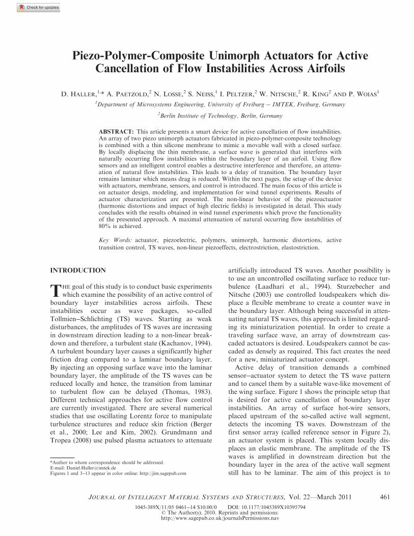
Active delay of transition demands a combinedsensor�actuator system to detect the TS wave patternand to cancel them by a suitable wave-like movement ofthe wing surface. Figure 1 shows the principle setup thatis desired for active cancellation of boundary layerinstabilities. An array of surface hot-wire sensors,placed upstream of the so-called active wall segment,detects the incoming TS waves. Downstream of thefirst sensor array (called reference sensor in Figure 2),an actuator system is placed. This system locally dis-places an elastic membrane. The amplitude of the TSwaves is amplified in downstream direction but theboundary layer in the area of the active wall segmentstill has to be laminar. The aim of this project is to
*Author to whom correspondence should be addressed.E-mail: [email protected] 1 and 3�13 appear in color online: http://jim.sagepub.com
JOURNAL OF INTELLIGENT MATERIAL SYSTEMS AND STRUCTURES, Vol. 22—March 2011 461
1045-389X/11/05 0461�14 $10.00/0 DOI: 10.1177/1045389X10395794� The Author(s), 2010. Reprints and permissions:http://www.sagepub.co.uk/journalsPermissions.nav
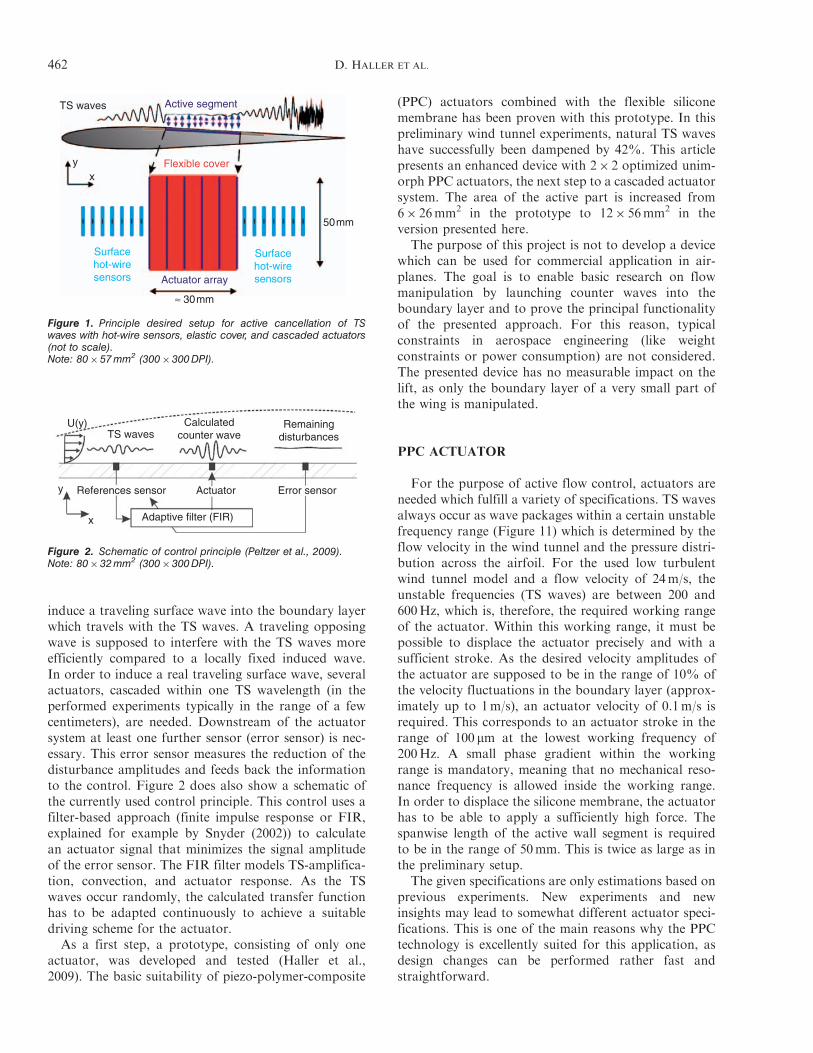
induce a traveling surface wave into the boundary layerwhich travels with the TS waves. A traveling opposingwave is supposed to interfere with the TS waves moreefficiently compared to a locally fixed induced wave.In order to induce a real traveling surface wave, severalactuators, cascaded within one TS wavelength (in theperformed experiments typically in the range of a fewcentimeters), are needed. Downstream of the actuatorsystem at least one further sensor (error sensor) is nec-essary. This error sensor measures the reduction of thedisturbance amplitudes and feeds back the informationto the control. Figure 2 does also show a schematic ofthe currently used control principle. This control uses afilter-based approach (finite impulse response or FIR,explained for example by Snyder (2002)) to calculatean actuator signal that minimizes the signal amplitudeof the error sensor. The FIR filter models TS-amplifica-tion, convection, and actuator response. As the TSwaves occur randomly, the calculated transfer functionhas to be adapted continuously to achieve a suitabledriving scheme for the actuator.As a first step, a prototype, consisting of only one
actuator, was developed and tested (Haller et al.,2009). The basic suitability of piezo-polymer-composite
(PPC) actuators combined with the flexible siliconemembrane has been proven with this prototype. In thispreliminary wind tunnel experiments, natural TS waveshave successfully been dampened by 42%. This articlepresents an enhanced device with 2� 2 optimized unim-orph PPC actuators, the next step to a cascaded actuatorsystem. The area of the active part is increased from6� 26mm2 in the prototype to 12� 56mm2 in theversion presented here.
The purpose of this project is not to develop a devicewhich can be used for commercial application in air-planes. The goal is to enable basic research on flowmanipulation by launching counter waves into theboundary layer and to prove the principal functionalityof the presented approach. For this reason, typicalconstraints in aerospace engineering (like weightconstraints or power consumption) are not considered.The presented device has no measurable impact on thelift, as only the boundary layer of a very small part ofthe wing is manipulated.
PPC ACTUATOR
For the purpose of active flow control, actuators areneeded which fulfill a variety of specifications. TS wavesalways occur as wave packages within a certain unstablefrequency range (Figure 11) which is determined by theflow velocity in the wind tunnel and the pressure distri-bution across the airfoil. For the used low turbulentwind tunnel model and a flow velocity of 24m/s, theunstable frequencies (TS waves) are between 200 and600Hz, which is, therefore, the required working rangeof the actuator. Within this working range, it must bepossible to displace the actuator precisely and with asufficient stroke. As the desired velocity amplitudes ofthe actuator are supposed to be in the range of 10% ofthe velocity fluctuations in the boundary layer (approx-imately up to 1m/s), an actuator velocity of 0.1m/s isrequired. This corresponds to an actuator stroke in therange of 100 mm at the lowest working frequency of200Hz. A small phase gradient within the workingrange is mandatory, meaning that no mechanical reso-nance frequency is allowed inside the working range.In order to displace the silicone membrane, the actuatorhas to be able to apply a sufficiently high force. Thespanwise length of the active wall segment is requiredto be in the range of 50mm. This is twice as large as inthe preliminary setup.
The given specifications are only estimations based onprevious experiments. New experiments and newinsights may lead to somewhat different actuator speci-fications. This is one of the main reasons why the PPCtechnology is excellently suited for this application, asdesign changes can be performed rather fast andstraightforward.
TS waves
Actuator array
≈ 30mm
50mm
Flexible coveryx
Surfacehot-wiresensors
Surfacehot-wiresensors
Active segment
Figure 1. Principle desired setup for active cancellation of TSwaves with hot-wire sensors, elastic cover, and cascaded actuators(not to scale).Note: 80� 57 mm2 (300�300 DPI).
U(y)
y
x
TS waves
References sensor Error sensorActuator
Adaptive filter (FIR)
Calculatedcounter wave
Remainingdisturbances
Figure 2. Schematic of control principle (Peltzer et al., 2009).Note: 80� 32 mm2 (300�300 DPI).
462 D. HALLER ET AL.
Actuator Design and Modeling
The chosen actuator principle is a unimorph actuatormade from a bilayer of a piezoceramic material and anepoxy polymer, as shown in Figure 3. Applying a volt-age to the piezoceramic leads to a contraction or elon-gation of the ceramic material. Due to the polymerlayer adhering on one side of the piezo sheet, a non-homogeneous mechanical stress distribution, andhence, a bending moment is induced into the bilayer.This leads to a vertical bending of the cantilever. Forcalculating the actuator static displacement, the classicallaminated plate theory (CLPT) using Kirchhoff assump-tions is applied (Reddy, 2004). For narrow unimorphactuators, the displacements and resultant componentsare independent from the y-coordinate (Yao et al.,2004a), meaning the model can be reduced to a modelin which the displacement only depends on the x-coor-dinate. As the applied electric fields will be very high,non-linear effects in the piezoelectric material will have asignificant impact on the characteristics of the unimorph(Wang et al., 1999). Therefore, these non-linear materialeffects have to be considered in the theory which will beused for designing the unimorph actuator. For the givencase (electric field only in z-direction, no mechanicalconstraints in y- and z-directions), the mechanical ten-sion in x-direction of a pure piezoceramic with appliedelectric field, including the non-linear material effectselectrostriction and elastostriction, can be written inVoigt notation as (Joshi, 1992):
�1 ¼"1
s11þ �113ð ÞE3�
d31þ12 a133E3
� �E3
s11þK113E3ð Þ
¼ C�11"1�X�31C�11E3, ð1Þ
with d31 being the linear piezoelectric strain coefficient,a133 the electrostrictive coefficient, s11 the complaisant
coefficient, and �113 the elastostrictive coefficient. Thisequation can be rewritten into a more familiar versionwith C�11 being a kind of effective, field-dependent stiff-ness including the elastostrictive effect and X�31 an effec-tive, field-dependent piezoelectric strain coefficient,including the electrostrictive effect. For small strainsand rotations, the strain-to-displacement ratio in acantilever is given by (Reddy, 2004):
"1 ¼@u
@xþ1
2
@w
@x
� �2
¼@u0@xþ1
2
@w0
@x
� �2
� z� zsð Þ@2w0
@x2, ð2Þ
where u is the axial displacement in x-direction and wthe transverse deflection in z-direction. The index0 denotes the displacement at the neutral plane andzs the location of the neutral plane. In the given coordi-nate system of Figure 3, the neutral plane depending onthe effective stiffness and thus, the electric field, can becalculated as:
1
2
�Ypolyhpoly2 þ c�11hPZT 2
Ypolyhpoly þ c�11hPZT: ð3Þ
The equations of motion for the considerednarrow cantilever can be written in the following form(Reddy, 2004):
@Nx
@x¼ m�
@2u0@t2
, ð4Þ
@2Mx
@x2þNx
@2w0
@x2¼ m�
@2w0
@t2� q, ð5Þ
with m* being the mass resultant of inertia per lengthand q denoting a distributed mechanical line load. Thevariables Nx and Mx indicate the stress resultant and themoment resultant, respectively. They can be calculatedas following, using Equations (1) and (2):
Nx ¼ b
Z 0
�hpoly
�1,poly dzþ b
Z hPZT
0
�1,PZTdz
¼ A11@u0@xþ1
2
@w0
@x
� �2
�B11@2w0
@x2�Np
x,
ð6Þ
Mx ¼ b
Z 0
�hpoly
�1,poly z� zsð Þdzþ
Z hPZT
0
�1,PZT z� zsð Þdz
¼ B11@u0@xþ1
2
@w0
@x
� �2
�D11@2w0
@x2�NP
x : ð7Þ
For the given case, the extensional stiffness A11, thebending�extensional coupling stiffness B11, the bending
Clamping
L
DwPassive layer
Passive layer(polymer)
Piezoceramic
Piezolayer
b
hPoly
hPZT
Vy
y
z
z
x
Figure 3. Schematic of unimorph actuator: top, 3D schematic;bottom, cross-section.Note: 80�64 mm2 (300�300 DPI).
Piezo-Polymer-Composite Unimorph Actuators 463
stiffness D11, the actuator force resultant NPx and the
actuator moment resultant MPx are:
A11 ¼ b Ypolyhpoly þ C�11hPZT� �
, ð8Þ
B11 ¼ b YPolyhPoly �1
2hPoly � zS
� ��
þC�11hPZT1
2hPZT � zS
� ��, ð9Þ
D11 ¼ b YPolyhPoly1
3hPoly2 þ hPolyzS þ z2S
� ��
þC�11hPZT1
3hPoly2 � hPolyzS þ z2S
� ��, ð10Þ
NPx ¼ bX�31C
�11E3hPZT, ð11Þ
MPx ¼ bX �31C
�11E3hPZT
1
2hPZT � zS
� �: ð12Þ
The static displacement of a unimorph actuator cannow be calculated by solving the equations of motion forstatic case with no external load and applying theboundary conditions of a one-sided clamped cantilever(Yao et al., 2004b). The result is:
w xð Þ ¼1
2
B11NPx � A11M
Px
A11D11 � B211
� �x2: ð13Þ
Putting the result for the neutral plane of Equation (3)into the expression for the bending�extensionalcoupling stiffness B11 (Equation (9)) delivers the resultthat B11 is actually 0. Thus, Equation (13) can besimplified to:
w xð Þ ¼1
2
MPx
D11x2: ð14Þ
Calculating the eigenfrequency of the given unimorphactuator is somewhat more complex. AdjustingEquation (5) to the considered case (no external loads)delivers for the non-static case:
�D11@4MP
x
@x4¼ m�
@2w0
@t2: ð15Þ
This partial derivative can be solved using a Bernoulliapproach (Maurizi et al., 1976) leading to an expressionfor the eigenfrequency:
fi ¼ 2��iL2
ffiffiffiffiffiffiffiffiffiffiffiD11
m�,
rð16Þ
where �i denotes the eigenvalue of the ith eigenfre-quency. In this study, only the first eigenfrequency is
of importance. For a cantilever clamped at one side,the first eigenvalue is 1.875. This solution only holdsfor a cantilever with no additional mass. An engineeringapproach can be used to enhance this expression forcantilevers with additional seismic mass. In thisapproach, the cantilever is considered as a mass�springsystem. The equivalent spring constant can be approxi-mated by calculating an equivalent force which, ifapplied at the tip of the cantilever, displaces the cantile-ver the same distance as the resulting bending momentMP
x . The equivalent mass is the additional mass plus themass of the cantilever. As the mass of the cantilever isdistributed along the cantilever, it is not fully acting onthe spring and has to be weighted with a factor smallerthan 1. The resulting expression for the eigenfrequencyof a unimorph actuator with additional mass at thetip is:
The coefficient �eff is determined to be 35/144 bysetting the seismic mass equal to zero and comparingEquation (17) with Equation (16).
The resulting expressions of Equations (14) and (17)can now be used to find the optimum design parameters.The height of the piezoceramic (260mm) is determinedby the manufacturer. The actuator width, as long as it isin a reasonable range, has a very limited influence on theactuator displacement and resonance frequency.Therefore, the width is set to 5mm. A larger widthwill not increase the actuator performance significantly,but it will increase the electric capacitance. This leavestwo design parameters which can be optimized: the actu-ator length and the polymer layer height. Table 1 showsall the required material properties. The parametersfrom the polymer (an epoxy resin, Stycast 2057 fromEmerson & Cumming) are determined by characterizingspecial test beams made only from the used polymer.The linear material constants for the used piezoceramicmaterial (VIBRIT1100 from Johnson MattheyCatalysts) are taken from the manufacturer data sheet.
The non-linear parameters are not given by the manu-facturer. For the used piezoelectric material they aredetermined by Wischke et al. (2010).The elastostrictive coefficient is negative, meaning
that the effective stiffness is increasing with an increas-ing applied voltage. An increased material stiffness leadsto an increased bending stiffness and therefore, accord-ing to Equation (17), an increased eigenfrequency. Theelectrostrictive coefficient has no influence on the eigen-frequency. The static displacement depends on bothnon-linear parameters. The increased material stiffnessincreases the bending stiffness but also the bendingmoment, leading to no significant impact of the elastos-trictive effect on the static displacement. The electro-strictive effect increases the bending momentsignificantly for high applied electric fields. Dependingon the geometric design parameters, the electrostrictiveeffect leads to a doubling of the bending momentcompared to considering only linear effects (Wischkeet al., 2010).The task is not only to maximize the displacement,
but also to keep the resonance frequency higher thanthe maximum working frequency. Figure 4 shows thestatic displacement according to Equation (14) plottedover the calculated eigenfrequency according toEquation (17). The applied voltage is 150V (this corre-sponds to an electric field of 0.58 kV/mm), which willbe the highest allowed voltage in the experiments.In Figure 4, the actuator length, as well as the polymerlayer height, is varied. Each line represents a particularlength with an increasing polymer layer height. Thepolymer layer height always starts at 100 mm for eachlength. Each additional marker corresponds to an addi-tional 100 mm in the polymer layer height. Consideringthe displacement, there is an optimum ratio between thepiezoceramic and polymer layer heights, but the
eigenfrequencies are too small in this case. When look-ing at the maximum working frequency of 600Hz, itbecomes obvious that an increased actuator lengthwith an increased polymer layer height leads to anincreased displacement with equivalent eigenfrequency.The advantages become smaller with an increasing actu-ator length. For eigenfrequencies higher than the maxi-mum working frequency of 600Hz, there is no distinctdifference between an actuator length of 30 and 35mm.For this reason, the actuator length is set to 30mm. Thepolymer layer height is chosen to be 1600 mm. The result-ing analytical displacement for a voltage amplitude of150V is 104 mm and the eigenfrequency is 759Hz.A safety margin of 150Hz is added to the maximumworking frequency of 600Hz. If only linear materialeffects would have been considered (simply achievedby setting the electroelastic and electrostrictive coeffi-cient to zero), the analytical displacement would be61 mm and the eigenfrequency would be 745Hz.The difference in the eigenfrequency is small, whereasthe difference in displacement is almost 80%. Thelinear results match very well with 3D-finite elementmodeling simulations using standard simulation soft-ware (COMSOL) which considers only linear piezoelec-tric effects. A CAD-picture of the final design is shownin Figure 5. The final design actually consists of twounimorph cantilevers. The tips of the two cantileversare connected via a 50-mm long and 0.5-mm wide poly-mer plunger. The plunger is needed for locally displacingthe flexible cover over a longer spanwise distance.
Polymer layer (1600mm)
Polymer plunger2.2mm
20mm
5mm
50mm
500mm
Piezoceramic(260mm)
30m
m
Figure 5. Model of designed PPC actuator with two unimorphcantilevers and connecting plunger: top, 3D-view; bottom, viewfrom beneath.Note: 83�87 mm2 (300�300 DPI).
(Hz)
Figure 4. Analytical displacement vs analytical eigenfrequency.Non-linear consideration with an input voltage of 150 VNote: 74�59 mm2 (300�300 DPI).
Piezo-Polymer-Composite Unimorph Actuators 465
This rather long and fragile plunger also explains theneed for having two cantilevers in parallel. The twoparallel cantilevers will be connected to the same voltagesource and only have the task to support the plunger attwo positions in order to prevent an oscillation of theplunger. The weight of the plunger has been consideredin Figure 4 according to Equation (17). Since the plun-ger is carried by two cantilevers, half of the mass of theplunger is added as seismic mass. Later experimentsshow that the individual actuator behavior does notchange when the connection between the two parallelactuators is interrupted by separating the plunger.Therefore, considering the model, only one cantileverwith half of the plunger is justifiable, at least as longas the two cantilevers are driven in parallel which isthe case in this application. In the following chapters,the two cantilevers carrying one plunger will be denotedas one actuator.
Fabrication
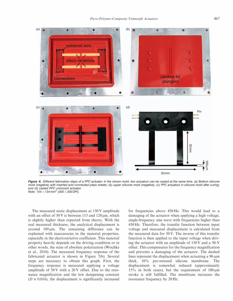
As mentioned before, the developed actuators arefabricated in PPC technology. In this technology, amilled aluminum mold (positive mold), representingthe geometry of the actuator, is casted with liquidsilicone to replicate a negative mold. In a second step,a piezoceramic sheet is inserted into the silicone (nega-tive) mold. Electrical connectors are also inserted intothe casting mold and soldered to the piezoceramic(shown in Figure 6(a)). Next, the liquid epoxy resin isadded into the silicone mold. A second half-mold isadded on top and the two halves are closed together.This second silicone mold is fabricated by castingan aluminum mold that represents the plungers(Figure 6(b)). After the polymer is cured at roomtemperature, the fabricated actuator can now beremoved from the silicone mold. The advantages ofthe PPC technology are a high-design flexibility andthe possibility to realize design chances within a shortperiod of time (Just et al., 2004). Using PPC technology,the very fragile plunger can be fabricated together withthe actuator within the same fabrication step. Through-holes for screwing the actuator on a mount can be real-ized easily in PPC technology.
Actuator Characteristics
The resonance frequency of several fabricated actua-tors, measured at 10V sinusoidal excitation and 0Voffset, varies between 660 and 690Hz. This is around10% smaller than expected from theory. There aredifferent reasons for this behavior. First of all, the thick-ness of the polymer layer is reduced due to shrinkageduring the curing of the polymer. The average measuredthickness of the polymer layer is 60 mm thinner than thedesigned thickness of 1600mm. This is a deviation of
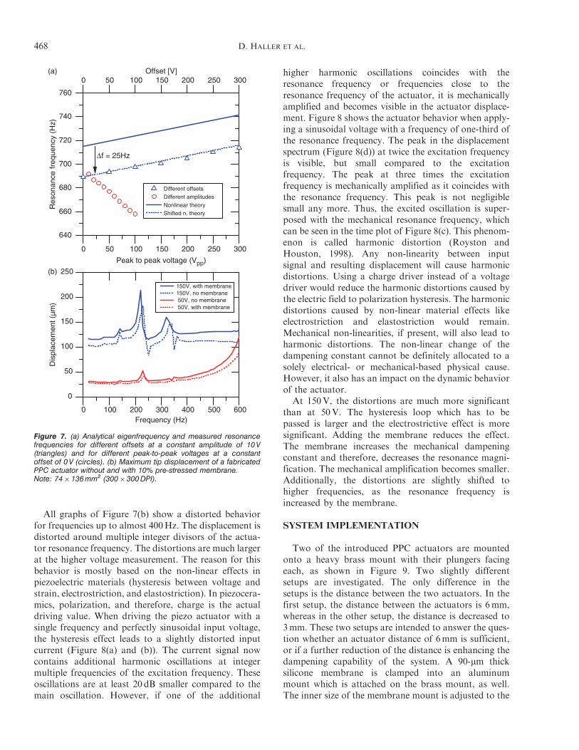
only 4%, but this deviation in the thickness reducesthe analytical resonance frequency by about 30Hz,leading to an analytical eigenfrequency of 716Hz.Additionally, the polymer layer thickness is slightlyinhomogeneous along the beam (in the range of�20 mm) and very small air bubbles can remain insidethe polymer which decreases the stiffness, as well.Furthermore, the theory assumes a perfect fixation atthe clamped end of the unimorph actuator. In reality,the clamped end is not perfectly fixed. Figure 7(a)shows the actuator resonance when driven with differentapplied voltages. First, the amplitude is kept constant at10V and the offset is increased from 0 to 300V. Theincreasing offset shifts the resonance frequency from691 to 715Hz. The analytical eigenfrequency accordingto Equation (17) is added in the graph. As stated above,there is a difference between analytical eigenfrequencyand measured resonance frequency. In the presentedcase, it is 25Hz at 0V offset. If the analytical eigenfre-quency is shifted by this constant deviation, the changeof resonance frequency depending on the voltage offsetis very well predicted by the presented non-linear model.
In the next experiment of Figure 7(a), the offset iskept constant at 0V and the voltage amplitude isincreased. In this case, the peak-to-peak voltage canonly be increased up to 100Vpp, as higher amplitudeslead to very high displacements at resonance whichcause the actuator to break. In contrast to the previousexperiment, the resonance frequency is now heavilydecreasing. This behavior can be explained by twodifferent effects. The first cause is heat generation dueto loss mechanisms in the piezoceramic (Uchino et al.,2006). The higher the voltage amplitude becomes, thehigher the generated heat and, therefore, the actuatortemperature becomes. In the performed experiments,the actuator temperature at the bearing reached up to35�C at the highest applied voltage in resonance. Theincreased temperature leads to a reduced material stiff-ness, especially of the polymer layer. The second, andmore dominating effect decreasing the actuator’s reso-nance frequency is a non-linear restoring force andspring constant. A unimorph actuator is a non-linearoscillator, also called Duffing oscillator. This meansthe spring constant depends on the displacement andthus, also the dampening constant of the unimorph actu-ator. The displacement magnification in resonance ofunimorph actuators decreases with an increasing electricfield. This means the dampening constant is increas-ing and the quality factor is decreasing (Wang et al.,1999). A higher dampening constant leads to a largerdifference between eigenfrequency and resonancefrequency. Therefore, the resonance frequencydecreases with an increasing applied voltage amplitude.Since the presented non-linear theory only calculatesthe eigenfrequency, this fact cannot be considered inthe theory.
466 D. HALLER ET AL.
The measured static displacement at 150V amplitudewith an offset of 50V is between 115 and 120 mm, whichis slightly higher than expected from theory. With thereal measured thickness, the analytical displacement isaround 109 mm. The remaining difference can beexplained with inaccuracies in the material properties,especially in the electrostrictive coefficient. This materialproperty heavily depends on the driving condition or inother words, the state of absolute polarization (Wischkeet al., 2010). The measured frequency response of thefabricated actuator is shown in Figure 7(b). Severalsteps are necessary to obtain this graph. First, thefrequency response is measured applying a voltageamplitude of 50V with a 20V offset. Due to the reso-nance magnification and the low dampening constant(D& 0.016), the displacement is significantly increased
for frequencies above 450Hz. This would lead to adamaging of the actuator when applying a high voltage,single-frequency sine wave with frequencies higher than450Hz. Therefore, the transfer function between inputvoltage and measured displacement is calculated fromthe measured data for 50V. The inverse of this transferfunction is then applied to the input voltage when driv-ing the actuator with an amplitude of 150V and a 50-Voffset. This compensates for the frequency magnificationand prevents a damaging of the actuator. The dashedlines represent the displacement when actuating a 90-mmthick, 10% pre-stressed silicone membrane. Thedisplacement is somewhat reduced (approximately15% in both cases), but the requirement of 100 mmstroke is still fulfilled. The membrane increases theresonance frequency by 20Hz.
(a) (b)
(c) (d)Pin
30m
m
50mm
500mm
Figure 6. Different fabrication steps of a PPC actuator. In the shown mold, two actuators can be casted at the same time. (a) Bottom siliconemold (negative) with inserted and connected piezo sheets; (b) upper silicone mold (negative); (c) PPC actuators in silicone mold after curing;and (d) casted PPC unimorph actuator.Note: 154�134 mm2 (300�300 DPI).
Piezo-Polymer-Composite Unimorph Actuators 467
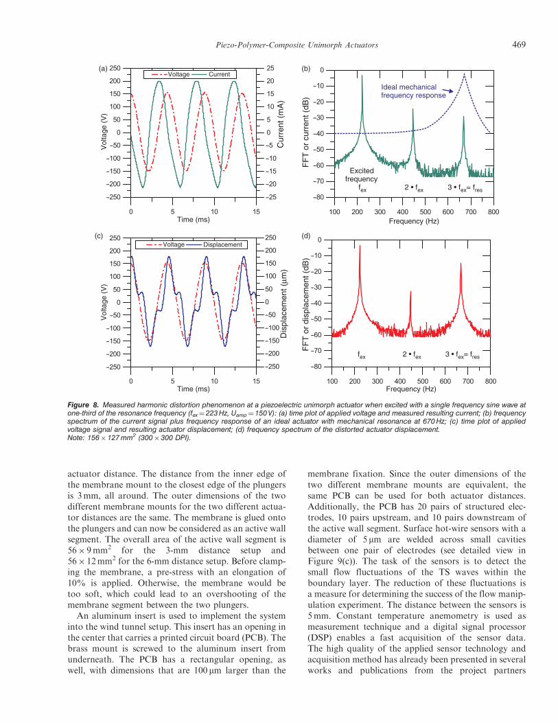
All graphs of Figure 7(b) show a distorted behaviorfor frequencies up to almost 400Hz. The displacement isdistorted around multiple integer divisors of the actua-tor resonance frequency. The distortions are much largerat the higher voltage measurement. The reason for thisbehavior is mostly based on the non-linear effects inpiezoelectric materials (hysteresis between voltage andstrain, electrostriction, and elastostriction). In piezocera-mics, polarization, and therefore, charge is the actualdriving value. When driving the piezo actuator with asingle frequency and perfectly sinusoidal input voltage,the hysteresis effect leads to a slightly distorted inputcurrent (Figure 8(a) and (b)). The current signal nowcontains additional harmonic oscillations at integermultiple frequencies of the excitation frequency. Theseoscillations are at least 20 dB smaller compared to themain oscillation. However, if one of the additional
higher harmonic oscillations coincides with theresonance frequency or frequencies close to theresonance frequency of the actuator, it is mechanicallyamplified and becomes visible in the actuator displace-ment. Figure 8 shows the actuator behavior when apply-ing a sinusoidal voltage with a frequency of one-third ofthe resonance frequency. The peak in the displacementspectrum (Figure 8(d)) at twice the excitation frequencyis visible, but small compared to the excitationfrequency. The peak at three times the excitationfrequency is mechanically amplified as it coincides withthe resonance frequency. This peak is not negligiblesmall any more. Thus, the excited oscillation is super-posed with the mechanical resonance frequency, whichcan be seen in the time plot of Figure 8(c). This phenom-enon is called harmonic distortion (Royston andHouston, 1998). Any non-linearity between inputsignal and resulting displacement will cause harmonicdistortions. Using a charge driver instead of a voltagedriver would reduce the harmonic distortions caused bythe electric field to polarization hysteresis. The harmonicdistortions caused by non-linear material effects likeelectrostriction and elastostriction would remain.Mechanical non-linearities, if present, will also lead toharmonic distortions. The non-linear change of thedampening constant cannot be definitely allocated to asolely electrical- or mechanical-based physical cause.However, it also has an impact on the dynamic behaviorof the actuator.
At 150V, the distortions are much more significantthan at 50V. The hysteresis loop which has to bepassed is larger and the electrostrictive effect is moresignificant. Adding the membrane reduces the effect.The membrane increases the mechanical dampeningconstant and therefore, decreases the resonance magni-fication. The mechanical amplification becomes smaller.Additionally, the distortions are slightly shifted tohigher frequencies, as the resonance frequency isincreased by the membrane.
SYSTEM IMPLEMENTATION
Two of the introduced PPC actuators are mountedonto a heavy brass mount with their plungers facingeach, as shown in Figure 9. Two slightly differentsetups are investigated. The only difference in thesetups is the distance between the two actuators. In thefirst setup, the distance between the actuators is 6mm,whereas in the other setup, the distance is decreased to3mm. These two setups are intended to answer the ques-tion whether an actuator distance of 6mm is sufficient,or if a further reduction of the distance is enhancing thedampening capability of the system. A 90-mm thicksilicone membrane is clamped into an aluminummount which is attached on the brass mount, as well.The inner size of the membrane mount is adjusted to the
(a)
(b)
640
660
680
700
720
740
760
Different offsetsDifferent amplitudesNonlinear theoryShifted n. theory
Res
onan
ce fr
eque
ncy
(Hz)
Peak to peak voltage (Vpp)
0 50 100 150 200 250 300Offset [V]
Δf = 25Hz
0 50 100 150 200 250 300
0 100 200 300 400 500 600
0
50
100
150
200
250
Dis
plac
emen
t (µm
)
Frequency (Hz)
150V, with membrane 150V, no membrane 50V, no membrane 50V, with membrane
Figure 7. (a) Analytical eigenfrequency and measured resonancefrequencies for different offsets at a constant amplitude of 10 V(triangles) and for different peak-to-peak voltages at a constantoffset of 0 V (circles). (b) Maximum tip displacement of a fabricatedPPC actuator without and with 10% pre-stressed membrane.Note: 74� 136 mm2 (300� 300 DPI).
468 D. HALLER ET AL.
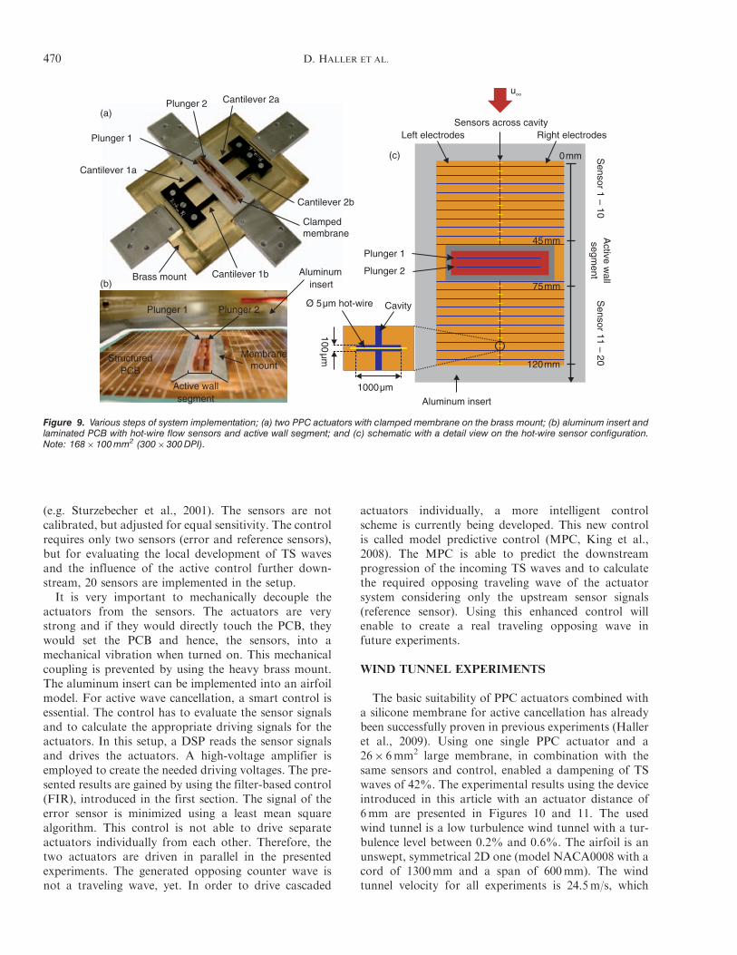
actuator distance. The distance from the inner edge ofthe membrane mount to the closest edge of the plungersis 3mm, all around. The outer dimensions of the twodifferent membrane mounts for the two different actua-tor distances are the same. The membrane is glued ontothe plungers and can now be considered as an active wallsegment. The overall area of the active wall segment is56� 9mm2 for the 3-mm distance setup and56� 12mm2 for the 6-mm distance setup. Before clamp-ing the membrane, a pre-stress with an elongation of10% is applied. Otherwise, the membrane would betoo soft, which could lead to an overshooting of themembrane segment between the two plungers.An aluminum insert is used to implement the system
into the wind tunnel setup. This insert has an opening inthe center that carries a printed circuit board (PCB). Thebrass mount is screwed to the aluminum insert fromunderneath. The PCB has a rectangular opening, aswell, with dimensions that are 100 mm larger than the
membrane fixation. Since the outer dimensions of thetwo different membrane mounts are equivalent, thesame PCB can be used for both actuator distances.Additionally, the PCB has 20 pairs of structured elec-trodes, 10 pairs upstream, and 10 pairs downstream ofthe active wall segment. Surface hot-wire sensors with adiameter of 5 mm are welded across small cavitiesbetween one pair of electrodes (see detailed view inFigure 9(c)). The task of the sensors is to detect thesmall flow fluctuations of the TS waves within theboundary layer. The reduction of these fluctuations isa measure for determining the success of the flow manip-ulation experiment. The distance between the sensors is5mm. Constant temperature anemometry is used asmeasurement technique and a digital signal processor(DSP) enables a fast acquisition of the sensor data.The high quality of the applied sensor technology andacquisition method has already been presented in severalworks and publications from the project partners
fex 2 • fex 3 • fex= fres
(a)
(c)
Ideal mechanicalfrequency response
Excitedfrequency
fex 2 • fex 3 • fex= fres
(b)
(d)
Vol
tage
(V
)V
olta
ge (
V)
Time (ms)
Time (ms)
Frequency (Hz)
Frequency (Hz)
Voltage
Voltage Displacement
Dis
plac
emen
t (mm
)
Current
Cur
rent
(m
A)
FF
T o
r cu
rren
t (dB
)F
FT
or
disp
lace
men
t (dB
)
Figure 8. Measured harmonic distortion phenomenon at a piezoelectric unimorph actuator when excited with a single frequency sine wave atone-third of the resonance frequency (fex¼ 223 Hz, Uamp¼ 150 V): (a) time plot of applied voltage and measured resulting current; (b) frequencyspectrum of the current signal plus frequency response of an ideal actuator with mechanical resonance at 670 Hz; (c) time plot of appliedvoltage signal and resulting actuator displacement; (d) frequency spectrum of the distorted actuator displacement.Note: 156�127 mm2 (300�300 DPI).
Piezo-Polymer-Composite Unimorph Actuators 469
(e.g. Sturzebecher et al., 2001). The sensors are notcalibrated, but adjusted for equal sensitivity. The controlrequires only two sensors (error and reference sensors),but for evaluating the local development of TS wavesand the influence of the active control further down-stream, 20 sensors are implemented in the setup.It is very important to mechanically decouple the
actuators from the sensors. The actuators are verystrong and if they would directly touch the PCB, theywould set the PCB and hence, the sensors, into amechanical vibration when turned on. This mechanicalcoupling is prevented by using the heavy brass mount.The aluminum insert can be implemented into an airfoilmodel. For active wave cancellation, a smart control isessential. The control has to evaluate the sensor signalsand to calculate the appropriate driving signals for theactuators. In this setup, a DSP reads the sensor signalsand drives the actuators. A high-voltage amplifier isemployed to create the needed driving voltages. The pre-sented results are gained by using the filter-based control(FIR), introduced in the first section. The signal of theerror sensor is minimized using a least mean squarealgorithm. This control is not able to drive separateactuators individually from each other. Therefore, thetwo actuators are driven in parallel in the presentedexperiments. The generated opposing counter wave isnot a traveling wave, yet. In order to drive cascaded
actuators individually, a more intelligent controlscheme is currently being developed. This new controlis called model predictive control (MPC, King et al.,2008). The MPC is able to predict the downstreamprogression of the incoming TS waves and to calculatethe required opposing traveling wave of the actuatorsystem considering only the upstream sensor signals(reference sensor). Using this enhanced control willenable to create a real traveling opposing wave infuture experiments.
WIND TUNNEL EXPERIMENTS
The basic suitability of PPC actuators combined witha silicone membrane for active cancellation has alreadybeen successfully proven in previous experiments (Halleret al., 2009). Using one single PPC actuator and a26� 6mm2 large membrane, in combination with thesame sensors and control, enabled a dampening of TSwaves of 42%. The experimental results using the deviceintroduced in this article with an actuator distance of6mm are presented in Figures 10 and 11. The usedwind tunnel is a low turbulence wind tunnel with a tur-bulence level between 0.2% and 0.6%. The airfoil is anunswept, symmetrical 2D one (model NACA0008 with acord of 1300mm and a span of 600mm). The windtunnel velocity for all experiments is 24.5m/s, which
Clampedmembrane
Brass mount
Cantilever 1a
Cantilever 2a
Cantilever 2b
Cantilever 1b
Plunger 1
Plunger 2
Plunger 1 Plunger 2
Active wallsegment
Aluminuminsert
StructuredPCB
Ø 5µm hot-wire
100µm
1000µm
Aluminum insert
Left electrodesS
ensor 11 – 20 S
ensor 1 – 10A
ctive wall
segment
Cavity
Right electrodesSensors across cavity
Plunger 1
Plunger 2
u∞
(c)
(a)
(b)
Membranemount
0mm
45mm
75mm
120mm
Figure 9. Various steps of system implementation; (a) two PPC actuators with clamped membrane on the brass mount; (b) aluminum insert andlaminated PCB with hot-wire flow sensors and active wall segment; and (c) schematic with a detail view on the hot-wire sensor configuration.Note: 168�100 mm2 (300�300 DPI).
470 D. HALLER ET AL.
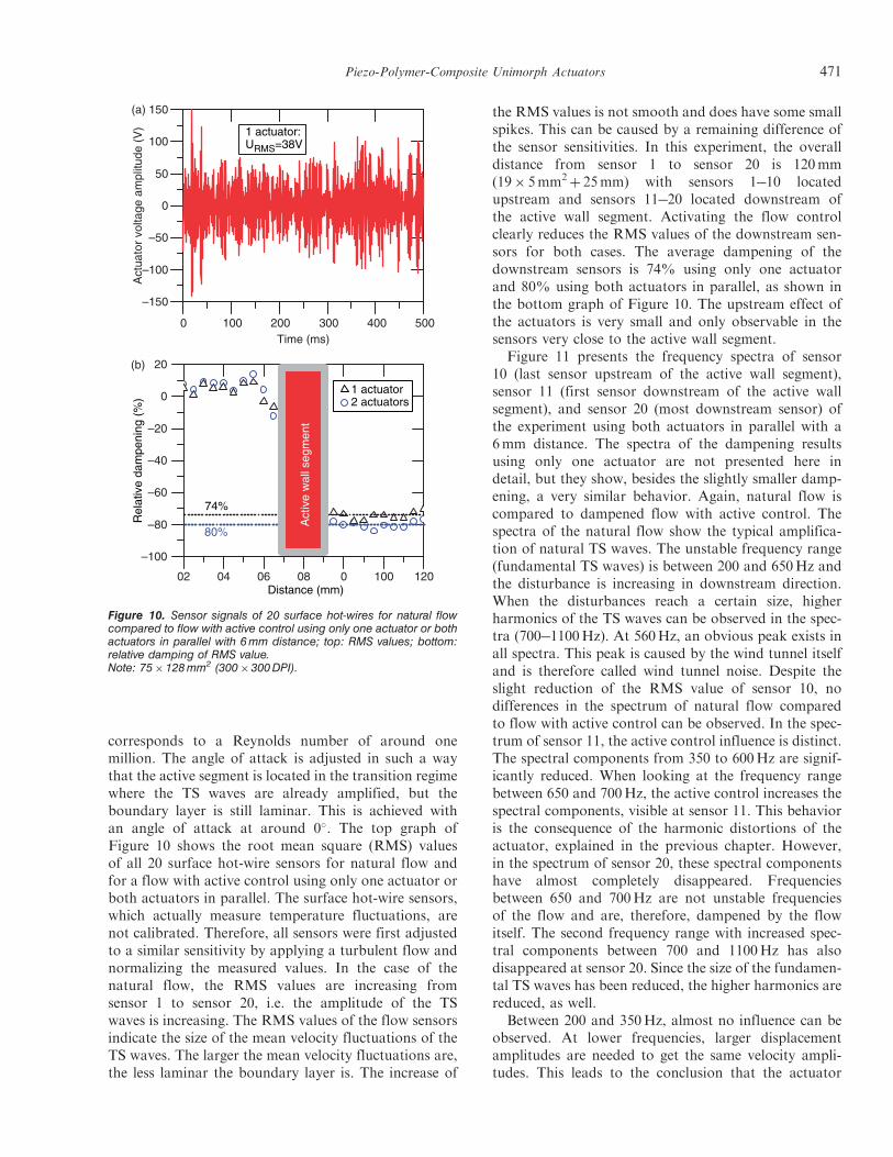
corresponds to a Reynolds number of around onemillion. The angle of attack is adjusted in such a waythat the active segment is located in the transition regimewhere the TS waves are already amplified, but theboundary layer is still laminar. This is achieved withan angle of attack at around 0�. The top graph ofFigure 10 shows the root mean square (RMS) valuesof all 20 surface hot-wire sensors for natural flow andfor a flow with active control using only one actuator orboth actuators in parallel. The surface hot-wire sensors,which actually measure temperature fluctuations, arenot calibrated. Therefore, all sensors were first adjustedto a similar sensitivity by applying a turbulent flow andnormalizing the measured values. In the case of thenatural flow, the RMS values are increasing fromsensor 1 to sensor 20, i.e. the amplitude of the TSwaves is increasing. The RMS values of the flow sensorsindicate the size of the mean velocity fluctuations of theTS waves. The larger the mean velocity fluctuations are,the less laminar the boundary layer is. The increase of
the RMS values is not smooth and does have some smallspikes. This can be caused by a remaining difference ofthe sensor sensitivities. In this experiment, the overalldistance from sensor 1 to sensor 20 is 120mm(19� 5mm2
þ 25mm) with sensors 1�10 locatedupstream and sensors 11�20 located downstream ofthe active wall segment. Activating the flow controlclearly reduces the RMS values of the downstream sen-sors for both cases. The average dampening of thedownstream sensors is 74% using only one actuatorand 80% using both actuators in parallel, as shown inthe bottom graph of Figure 10. The upstream effect ofthe actuators is very small and only observable in thesensors very close to the active wall segment.
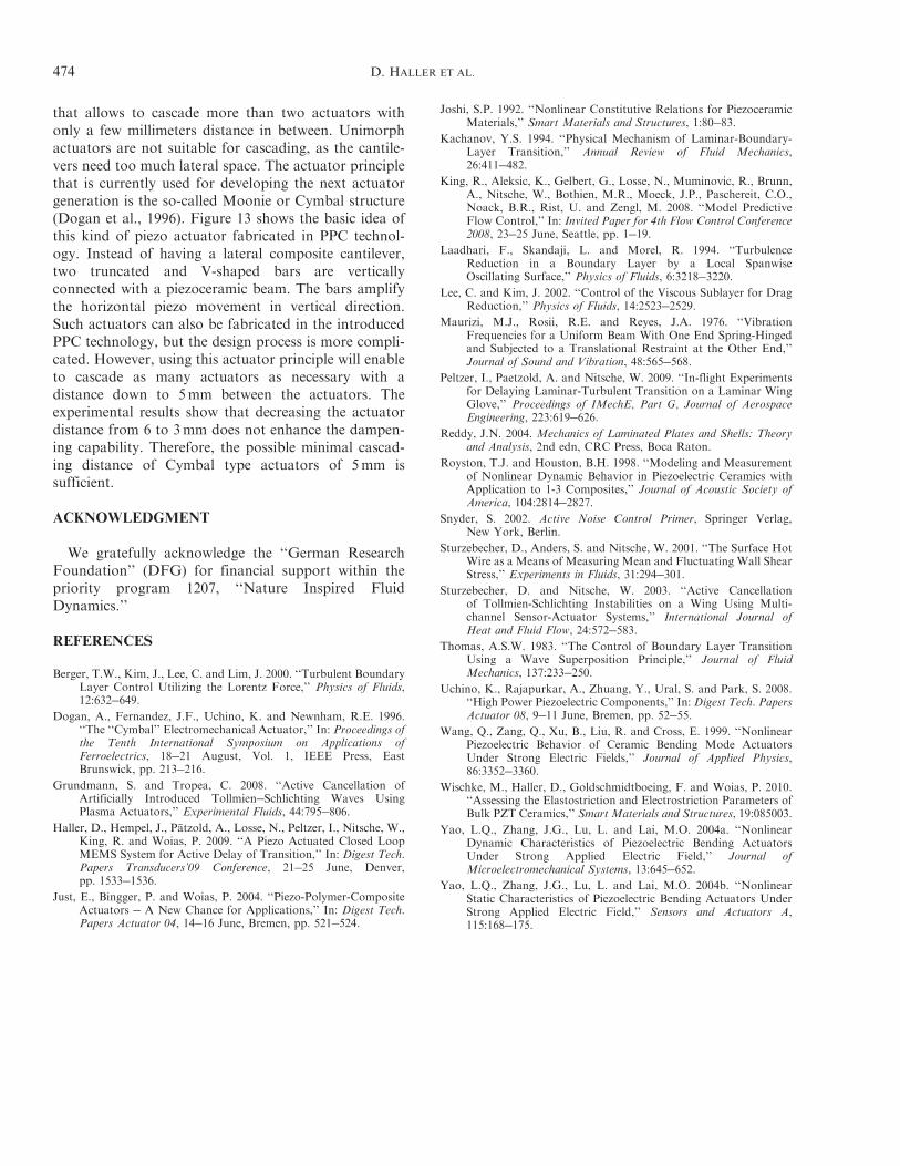
Figure 11 presents the frequency spectra of sensor10 (last sensor upstream of the active wall segment),sensor 11 (first sensor downstream of the active wallsegment), and sensor 20 (most downstream sensor) ofthe experiment using both actuators in parallel with a6mm distance. The spectra of the dampening resultsusing only one actuator are not presented here indetail, but they show, besides the slightly smaller damp-ening, a very similar behavior. Again, natural flow iscompared to dampened flow with active control. Thespectra of the natural flow show the typical amplifica-tion of natural TS waves. The unstable frequency range(fundamental TS waves) is between 200 and 650Hz andthe disturbance is increasing in downstream direction.When the disturbances reach a certain size, higherharmonics of the TS waves can be observed in the spec-tra (700�1100Hz). At 560Hz, an obvious peak exists inall spectra. This peak is caused by the wind tunnel itselfand is therefore called wind tunnel noise. Despite theslight reduction of the RMS value of sensor 10, nodifferences in the spectrum of natural flow comparedto flow with active control can be observed. In the spec-trum of sensor 11, the active control influence is distinct.The spectral components from 350 to 600Hz are signif-icantly reduced. When looking at the frequency rangebetween 650 and 700Hz, the active control increases thespectral components, visible at sensor 11. This behavioris the consequence of the harmonic distortions of theactuator, explained in the previous chapter. However,in the spectrum of sensor 20, these spectral componentshave almost completely disappeared. Frequenciesbetween 650 and 700Hz are not unstable frequenciesof the flow and are, therefore, dampened by the flowitself. The second frequency range with increased spec-tral components between 700 and 1100Hz has alsodisappeared at sensor 20. Since the size of the fundamen-tal TS waves has been reduced, the higher harmonics arereduced, as well.
Between 200 and 350Hz, almost no influence can beobserved. At lower frequencies, larger displacementamplitudes are needed to get the same velocity ampli-tudes. This leads to the conclusion that the actuator
(a)
(b)
0 100 200 300 400 500
–150
–100
–50
0
50
100
150
1 actuator:URMS=38V
Act
uato
r vo
ltage
am
plitu
de (
V)
Time (ms)
02 04 06 08 0 100 120
–100
–80
–60
–40
–20
0
20
74%
1 actuator2 actuators
Rel
ativ
e da
mpe
ning
(%
)
Distance (mm)
80%
A
ctiv
e w
all s
egm
ent
Figure 10. Sensor signals of 20 surface hot-wires for natural flowcompared to flow with active control using only one actuator or bothactuators in parallel with 6 mm distance; top: RMS values; bottom:relative damping of RMS value.Note: 75�128 mm2 (300�300 DPI).
Piezo-Polymer-Composite Unimorph Actuators 471
stroke seems to be not sufficiently high, but this assump-tion is disproved by looking at the actuation voltage,presented in Figure 12. The control is allowed toincrease the voltage up to a maximum limit set to�150V (the 50V constant offset is added afterward).In fact, the applied voltage of the control never crossed�60V when using both actuators. In principle, the actu-ator would be able to deliver a higher stroke, but thecontrol does not demand a higher actuator stroke.Therefore, the control has to be improved, as the actu-ator performance is not limiting the dampening capabil-ity of the system. Comparing the actuation voltagesusing one or two actuators shows that the required actu-ation voltage, and hence, the required actuator stroke, issmaller when using both actuators. The effective voltageis reduced from 38 to 29V. The maximum required
voltage during the full 5-s long recorded actuationsignal is reduced from 150V using one actuator toslightly above 60V using both actuators.
In comparison to the above-presented results, thesetup with a 3-mm actuator distance shows a verysimilar behavior and is therefore not shown in detail,here. The mean dampening of the RMS values is 72%using both actuators in parallel. This is slightly worse asthe dampening results of the setup with 6mm distancebetween the actuators. The spectra of the dampenedflow show the same characteristics (good dampeningfor higher frequencies and almost no dampening forfrequencies below 350Hz) and the maximal requiredactuation voltage is also 60V. The dampening capabilityis not enhanced by reducing the actuator distance from6 to 3mm.
Sensor
11 – 20S
ensor1 – 10
Active w
allsegm
ent
u∞
Sensor 10
Sensor 11
Sensor 20
Natural flowDampened flow
Natural flowDampened flow
Natural flowDampened flow
Higher harmonicsof TS wavesHarmonic
distortions
Fundamental TS waves
Frequency (Hz)
FF
T o
f sen
sor
10 (
dB)
FF
T o
f sen
sor
11 (
dB)
FF
T o
f sen
sor
20 (
dB)
Frequency (Hz) Frequency (Hz)
Figure 11. Frequency spectrum of sensor 10 (5 mm upstream of active wall segment), sensor 11 (5 mm downstream of active wall segment),and sensor 20 (50 mm downstream of active wall segment). The results are taken from the experiment with 6 mm actuator distance and usingboth actuators in parallel.Note: 153�134 mm2 (300�300 DPI).
472 D. HALLER ET AL.
CONCLUSION AND OUTLOOK
The developed non-linear actuator model, consideringthe electrostrictive and the elastostrictive effects, enabledan appropriate design and optimization process for therequired unimorph actuators. On the one hand, themeasured actuator characteristics correspond very wellto the predicted actuator behavior. On the other hand,the developed unimorph actuators show some additionaldynamic non-linearities, mainly the so-called harmonicdistortions. This effect can be explained by the staticnon-linearities of the piezoelectric material.
The developed actuator is combined with a siliconemembrane and implemented into a wind tunnel setup.The dampening capability of the full setup is successfullyproven in wind tunnel experiments. Using two cascadedactuators and increasing the area of the active wallsegment in spanwise and in downstream directionenhanced the dampening of natural TS waves from42% using the preliminary setup up to 80% when eval-uating the new developed setup with twice the dimensionin spanwise direction and two cascaded actuators. Whendisconnecting the second actuator and driving only oneactuator, the dampening capability is somewhat reduced(74%). This proofs that injecting the counter wave overa larger area is advantageous for dampening the TSwaves. The individual required actuator stroke of eachactuator is smaller when two actuators are used. Theapplied maximum actuation voltages in the differentdampening experiments correspond to an actuatorstroke of around 40 mm using both actuators and100 mm using only one actuator. The experiments showthat the actuator performance is sufficient for the appli-cation and the system implementation has proven to besuccessful. A further optimization of the actuator strokewill not lead to an improvement in dampening the TSwaves as already only a part of the full possible actuatorstroke is required by the control. TS waves with highfrequencies have been dampened very well. In contrast,TS waves with low frequencies have been attenuatedvery little. This leaves room for optimization.An increased active area should in principle be able toinject a surface wave with a larger wavelength. Thisshould enhance the dampening of low frequency TSwaves. Additionally, based on the experimental results,an even larger active area is supposed to require an evensmaller individual actuator displacement. This is animportant insight regarding the development of an actu-ator concept which is suitable for numerous cascading inthe required distances. Harmonic distortions caused bythe non-linear effects of the piezoelectric material doesinfluence the boundary layer but in an acceptable way.Two basic steps are necessary to further improve thisproject. First of all, the MPC has to be established, togenerate a real traveling wave instead of a locally fixedwave. The second step is to develop an actuator design
0 100 200 300 400 500
–150
–100
–50
0
50
100
150(a)
(b)
1 actuator:URMS=38V
Act
uato
r vo
ltage
am
plitu
de (
V)
Time (ms)
0 100 200 300 400 500
–150
–100
–50
0
50
100
1502 actuators:URMS=29V
App
lied
actu
ator
vol
tage
(V
)
Time (ms)
Figure 12. Applied actuation voltage using only one actuator(top, 74% dampening) or both actuators in parallel (bottom, 80%dampening).Note: 76�122 mm2 (300�300 DPI).
that allows to cascade more than two actuators withonly a few millimeters distance in between. Unimorphactuators are not suitable for cascading, as the cantile-vers need too much lateral space. The actuator principlethat is currently used for developing the next actuatorgeneration is the so-called Moonie or Cymbal structure(Dogan et al., 1996). Figure 13 shows the basic idea ofthis kind of piezo actuator fabricated in PPC technol-ogy. Instead of having a lateral composite cantilever,two truncated and V-shaped bars are verticallyconnected with a piezoceramic beam. The bars amplifythe horizontal piezo movement in vertical direction.Such actuators can also be fabricated in the introducedPPC technology, but the design process is more compli-cated. However, using this actuator principle will enableto cascade as many actuators as necessary with adistance down to 5mm between the actuators. Theexperimental results show that decreasing the actuatordistance from 6 to 3mm does not enhance the dampen-ing capability. Therefore, the possible minimal cascad-ing distance of Cymbal type actuators of 5mm issufficient.
ACKNOWLEDGMENT
We gratefully acknowledge the ‘‘German ResearchFoundation’’ (DFG) for financial support within thepriority program 1207, ‘‘Nature Inspired FluidDynamics.’’
REFERENCES
Berger, T.W., Kim, J., Lee, C. and Lim, J. 2000. ‘‘Turbulent BoundaryLayer Control Utilizing the Lorentz Force,’’ Physics of Fluids,12:632�649.
Dogan, A., Fernandez, J.F., Uchino, K. and Newnham, R.E. 1996.‘‘The ‘‘Cymbal’’ Electromechanical Actuator,’’ In: Proceedings ofthe Tenth International Symposium on Applications ofFerroelectrics, 18�21 August, Vol. 1, IEEE Press, EastBrunswick, pp. 213�216.
Grundmann, S. and Tropea, C. 2008. ‘‘Active Cancellation ofArtificially Introduced Tollmien�Schlichting Waves UsingPlasma Actuators,’’ Experimental Fluids, 44:795�806.
Haller, D., Hempel, J., Patzold, A., Losse, N., Peltzer, I., Nitsche, W.,King, R. and Woias, P. 2009. ‘‘A Piezo Actuated Closed LoopMEMS System for Active Delay of Transition,’’ In: Digest Tech.Papers Transducers’09 Conference, 21�25 June, Denver,pp. 1533�1536.
Just, E., Bingger, P. and Woias, P. 2004. ‘‘Piezo-Polymer-CompositeActuators � A New Chance for Applications,’’ In: Digest Tech.Papers Actuator 04, 14�16 June, Bremen, pp. 521�524.
Joshi, S.P. 1992. ‘‘Nonlinear Constitutive Relations for PiezoceramicMaterials,’’ Smart Materials and Structures, 1:80�83.
Kachanov, Y.S. 1994. ‘‘Physical Mechanism of Laminar-Boundary-Layer Transition,’’ Annual Review of Fluid Mechanics,26:411�482.
King, R., Aleksic, K., Gelbert, G., Losse, N., Muminovic, R., Brunn,A., Nitsche, W., Bothien, M.R., Moeck, J.P., Paschereit, C.O.,Noack, B.R., Rist, U. and Zengl, M. 2008. ‘‘Model PredictiveFlow Control,’’ In: Invited Paper for 4th Flow Control Conference2008, 23�25 June, Seattle, pp. 1�19.
Laadhari, F., Skandaji, L. and Morel, R. 1994. ‘‘TurbulenceReduction in a Boundary Layer by a Local SpanwiseOscillating Surface,’’ Physics of Fluids, 6:3218�3220.
Lee, C. and Kim, J. 2002. ‘‘Control of the Viscous Sublayer for DragReduction,’’ Physics of Fluids, 14:2523�2529.
Maurizi, M.J., Rosii, R.E. and Reyes, J.A. 1976. ‘‘VibrationFrequencies for a Uniform Beam With One End Spring-Hingedand Subjected to a Translational Restraint at the Other End,’’Journal of Sound and Vibration, 48:565�568.
Peltzer, I., Paetzold, A. and Nitsche, W. 2009. ‘‘In-flight Experimentsfor Delaying Laminar-Turbulent Transition on a Laminar WingGlove,’’ Proceedings of IMechE, Part G, Journal of AerospaceEngineering, 223:619�626.
Reddy, J.N. 2004. Mechanics of Laminated Plates and Shells: Theoryand Analysis, 2nd edn, CRC Press, Boca Raton.
Royston, T.J. and Houston, B.H. 1998. ‘‘Modeling and Measurementof Nonlinear Dynamic Behavior in Piezoelectric Ceramics withApplication to 1-3 Composites,’’ Journal of Acoustic Society ofAmerica, 104:2814�2827.
Snyder, S. 2002. Active Noise Control Primer, Springer Verlag,New York, Berlin.
Sturzebecher, D., Anders, S. and Nitsche, W. 2001. ‘‘The Surface HotWire as a Means of Measuring Mean and Fluctuating Wall ShearStress,’’ Experiments in Fluids, 31:294�301.
Sturzebecher, D. and Nitsche, W. 2003. ‘‘Active Cancellationof Tollmien-Schlichting Instabilities on a Wing Using Multi-channel Sensor-Actuator Systems,’’ International Journal ofHeat and Fluid Flow, 24:572�583.
Thomas, A.S.W. 1983. ‘‘The Control of Boundary Layer TransitionUsing a Wave Superposition Principle,’’ Journal of FluidMechanics, 137:233�250.
Uchino, K., Rajapurkar, A., Zhuang, Y., Ural, S. and Park, S. 2008.‘‘High Power Piezoelectric Components,’’ In: Digest Tech. PapersActuator 08, 9�11 June, Bremen, pp. 52�55.
Wang, Q., Zang, Q., Xu, B., Liu, R. and Cross, E. 1999. ‘‘NonlinearPiezoelectric Behavior of Ceramic Bending Mode ActuatorsUnder Strong Electric Fields,’’ Journal of Applied Physics,86:3352�3360.
Wischke, M., Haller, D., Goldschmidtboeing, F. and Woias, P. 2010.‘‘Assessing the Elastostriction and Electrostriction Parameters ofBulk PZT Ceramics,’’ Smart Materials and Structures, 19:085003.
Yao, L.Q., Zhang, J.G., Lu, L. and Lai, M.O. 2004a. ‘‘NonlinearDynamic Characteristics of Piezoelectric Bending ActuatorsUnder Strong Applied Electric Field,’’ Journal ofMicroelectromechanical Systems, 13:645�652.
Yao, L.Q., Zhang, J.G., Lu, L. and Lai, M.O. 2004b. ‘‘NonlinearStatic Characteristics of Piezoelectric Bending Actuators UnderStrong Applied Electric Field,’’ Sensors and Actuators A,115:168�175.