60
WWW.PI.WS PIglide Air Bearing Products & Technology NANOMETER PRECISION,MULTI-AXIS MOTION, STANDARD & CUSTOM DESIGNS
M O T I O N | P O S I T I O N I N G
BR
O59
E P
Iglid
e S
ub
cata
log
06/
2017
1. S
ub
ject
to
ch
ang
e w
ith
ou
t n
oti
ce. ©
Ph
ysik
Inst
rum
ente
(P
I) G
mb
H &
Co
. KG
201
7
W W W. P I . W S
PIglide Air Bearing Products & Technology
N A N O M E T E R P R E C I S I O N , M U LT I - A X I S M O T I O N , S T A N D A R D & C U S T O M D E S I G N S

W W W. P I . W S
2
FLEXIBLE AXIS CONFIGURATIONn Single axis linear stages
n Rotary stages
n XY Planar Scanners
n Non-motorized linear and rotary bearings
n Hemispherical bearings
n Rotary air bearing spindles
NANOMETER PRECISION, SINGLE- & MULTI-AXIS MOTION n Frictionless high-precision positioning
n Excellent velocity stability
n Excellent guiding accuracy up to 5 µrad/100 mm
n Active yaw control for gantries
n Direct drive linear & torque motors for smooth, high speed scanning
n State of the art controls powered by ACS Motion Control
EXPERIENCE WITH AIR BEARING TECHNOLOGY MATTERS FOR OEMS PI is building on over 200 man-years of in-house air bearing experience and offers comprehensive precision air bearing motion control and positioning products and systems. With more than 4 decades of experience in piezo nano-positioning systems design and motorized precision positioning equipment, the air bearing systems capabilities are a natural and logical extension of PI’s precision motion offerings.
The Step Ahead with Air Bearing Technology
PIg
lide
Tech
no
log
y
M O T I O N | P O S I T I O N I N G
3
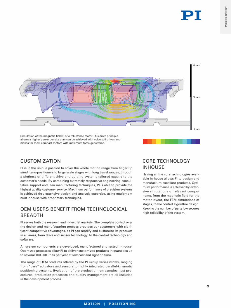
Simulation of the magnetic field B of a reluctance motor. This drive principle allows a higher power density than can be achieved with voice coil drives and makes for most compact motors with maximum force generation.
CUSTOMIZATIONPI is in the unique position to cover the whole motion range from finger-tip sized nano-positioners to large scale stages with long travel ranges, through a plethora of different drive and guiding systems tailored exactly to the customer’s needs. By combining extremely responsive engineering consul-tative support and lean manufacturing techniques, PI is able to provide the highest quality customer service. Maximum performance of precision systems is achieved thru extensive design and analysis expertise, using equipment built inhouse with proprietary techniques.
OEM USERS BENEFIT FROM TECHNOLOGICAL BREADTH PI serves both the research and industrial markets. The complete control over the design and manufacturing process provides our customers with signi-ficant competitive advantages, as PI can modify and customize its products in all areas, from drive and sensor technology, to the control technology and software.
All system components are developed, manufactured and tested in-house. Optimized processes allow PI to deliver customized products in quantities up to several 100,000 units per year at low cost and right on time.
The range of OEM products offered by the PI Group varies widely, ranging from “bare” actuators and sensors to highly integrated parallel-kinematic positioning systems. Evaluation of pre-production run samples, test pro- cedures, production processes and quality management are all included in the development process.
CORE TECHNOLOGY INHOUSEHaving all the core technologies avail- able in-house allows PI to design and manufacture excellent products. Opti- mum performance is achieved by exten-sive simulations of relevant compo- nents, from the magnetic field for the motor layout, the FEM simulations of stages, to the control algorithm design. Keeping the number of parts low secures high reliability of the system.
PIg
lide
Tech
no
log
y

W W W. P I . W S
4
Characteristics of Air Bearings
STRAIGHTNESS AND FLATNESSThe total error motion over full travel is usually specified in microns TIR (Total Indicator Reading). TIR is specifying the peak-to-peak measurement of error mo- tion. Symmetry about a zero reference is not assumed. Air bearing stages can typically achieve better than 1 µm flatness and straightness TIR for every 200 mm of travel.
VELOCITY STABILITY AND SCANNINGThe lack of mechanical bearing elements means there is nothing to get in the way of smooth, controlled velocity (stability to better than 0.01%). Experiments and processes like inertial sensor testing, tomography, wafer scanning, and surface profiling require continuous motion at tightly controlled speeds are best served by air bearing systems.
REPEATABILITY OF HIGH-PRECISION POSITIONINGA direct-drive motor and high-resolution encoder can position a moving carriage supported by an air bearing to within nanometers in a linear application or within tenths of arc-seconds in rotational applications. The lack of friction and mechanical contact means there is minimal vibration, hysteresis or reversal error, making it highly repeatable and ideal for many inspection and manufacturing operations. Stiction is virtually eliminated, improving resolution capabilities and reducing in-position “hunting” (limit cycling). Position repeatability can be obtained within a few fundamental encoder counts. Similar precision can be obtained by piezo flexure guided stages, however over much smaller travel ranges. Magnetic levitation is another option.
Typical specifications are:
Linear: Straightness/Flatness 0.1 µm/25 mm, Pitch/Yaw 0.5 arcsec/25 mm Rotary: Radial/Axial Runout 0.1 µm, Wobble <1 arcsec
PIg
lide
Tech
no
log
y

M O T I O N | P O S I T I O N I N G
5
Magnetic Direct Drive Technology
PIMag®
Magnetic levitation guides achieve ultimate precision in this linear motor driven technology study
Dynamic 6-axis positioning with voice coil drives, H-860 hexapod
Drive technology and control know-how as well as an expertise in bearings and encoders allow for a broad range of motors for system integration. Proprietary developments also include high-resolution force sensors for manufacturing and test equipment.
Ironless Linear Motors
n High acceleration and velocity
n Linear stages, planar scanners, PIMag® 6D positioning system
n Torque motors for rotation stagesVoice Coil Drives
n High dynamics for fast scanning and positioning
n OEM actuators, linear scanners, Hexapods
n Optional force sensors
Drive Technology Beyond Standard
n Highest accelerations up to 60 g with resonance motor
n Highest force density for single phase linear motors with reluctance motor and cylindrical Halbach arrays
n High force density and low weight with linear Halbach arrays
Guiding Systems
n PIglide air bearings for frictionless motion and optimum straightness and flatness
n Active magnetic guidings align flatness during motion
n Flexure guidings provide friction- less motion over short strokes
n Ball and roller bearings from the leading suppliers
PIg
lide
Tech
no
log
y

W W W. P I . W S
6
High Performance Small Footprint Nanopositioning Stage
A-121 PIglide AT1 Linear Stage with Air Bearings
Accessories and options
n Encoder
n PIglide filter and air preparation kits
n Multi-axis motion controller and servo drives
n XY setups and individual configurations
n Cable track variations
n Counterbalance options for vertical assembly
n Base plates made of granite and systems for reducing vibration
Fields of application
PIglide positioning systems are ideally suited for many high-precision applications, such as metrology, photonics, and precision scanning as well as in semiconductor or flat panel display manufacturing.
Thanks to the friction-free motion, no particles are formed, which makes PIglide stages ideal for cleanroom applications.
n Ideal for scanning applications or high-precision positioning
n Cleanroom compatible
n Size of the motion platform 115 mm × 115 mm
n Travel ranges to 350 mm
n Low profile of 60 mm
n Resolution to 1 nm
The PIglide AT1 series of air bearing stages is equipped with a servo drive linear motor with preloaded air bearings and integrated linear encoder. The combination of these non-contact components results in a frictionless motion platform that offers the highest performance, quality, and life.
A high-force linear motor can drive the stage to top speed within a few milliseconds. The dovetail preloaded air bearing design in this model will support normal, vertical, and side-mounted orientations.
Lin
ear
Air
Bea
rin
g
Sta
ges
M O T I O N | P O S I T I O N I N G
7
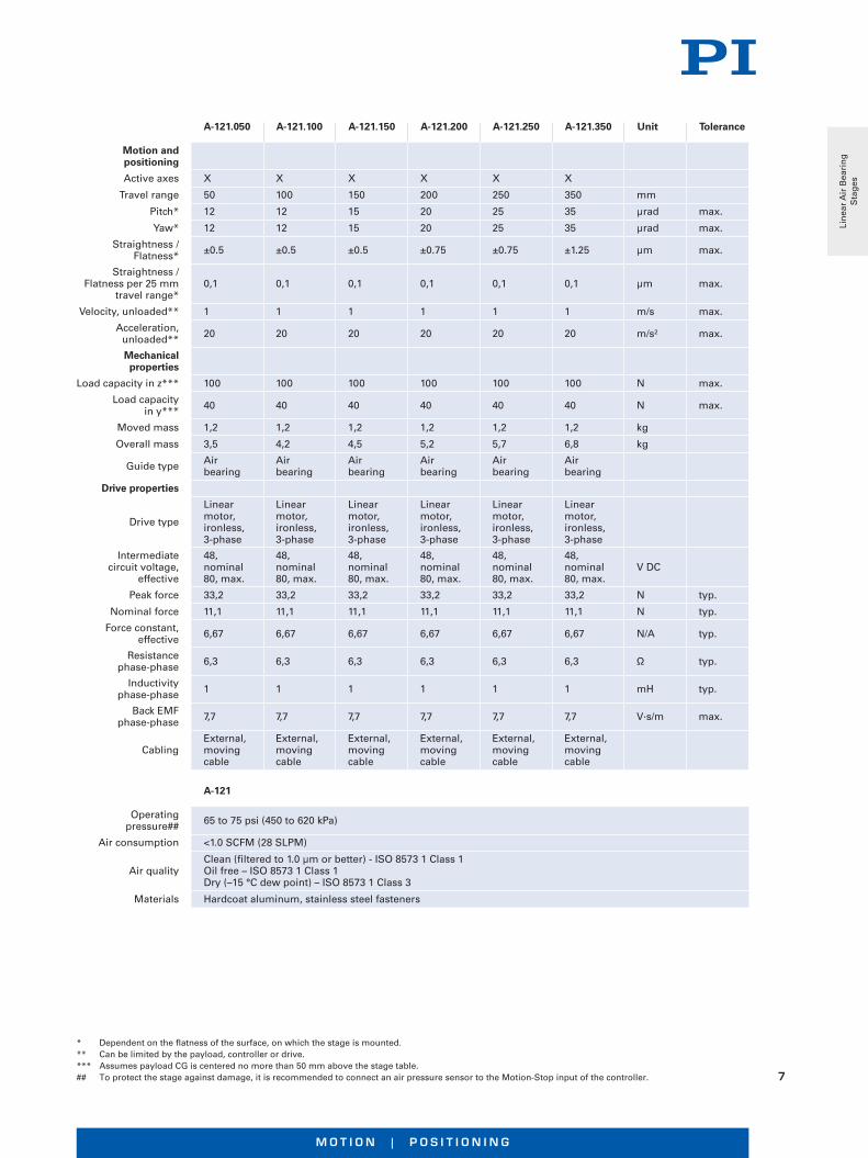
* Dependent on the flatness of the surface, on which the stage is mounted.** Can be limited by the payload, controller or drive.*** Assumes payload CG is centered no more than 50 mm above the stage table.## To protect the stage against damage, it is recommended to connect an air pressure sensor to the Motion-Stop input of the controller.
A-121.050 A-121.100 A-121.150 A-121.200 A-121.250 A-121.350 Unit Tolerance
Motion and positioning
Active axes X X X X X X
Travel range 50 100 150 200 250 350 mm
Pitch* 12 12 15 20 25 35 µrad max.
Yaw* 12 12 15 20 25 35 µrad max.
Straightness / Flatness* ±0.5 ±0.5 ±0.5 ±0.75 ±0.75 ±1.25 µm max.
Straightness / Flatness per 25 mm
travel range*0,1 0,1 0,1 0,1 0,1 0,1 µm max.
Velocity, unloaded** 1 1 1 1 1 1 m/s max.
Acceleration, unloaded** 20 20 20 20 20 20 m/s² max.
Mechanical properties
Load capacity in z*** 100 100 100 100 100 100 N max.
Load capacity in y*** 40 40 40 40 40 40 N max.
Moved mass 1,2 1,2 1,2 1,2 1,2 1,2 kg
Overall mass 3,5 4,2 4,5 5,2 5,7 6,8 kg
Guide type Air bearing
Air bearing
Air bearing
Air bearing
Air bearing
Air bearing
Drive properties
Drive type
Linear motor, ironless, 3-phase
Linear motor, ironless, 3-phase
Linear motor, ironless, 3-phase
Linear motor, ironless, 3-phase
Linear motor, ironless, 3-phase
Linear motor, ironless, 3-phase
Intermediate circuit voltage,
effective
48, nominal 80, max.
48, nominal 80, max.
48, nominal 80, max.
48, nominal 80, max.
48, nominal 80, max.
48, nominal 80, max.
V DC
Peak force 33,2 33,2 33,2 33,2 33,2 33,2 N typ.
Nominal force 11,1 11,1 11,1 11,1 11,1 11,1 N typ.
Force constant, effective 6,67 6,67 6,67 6,67 6,67 6,67 N/A typ.
Resistance phase-phase 6,3 6,3 6,3 6,3 6,3 6,3 Ω typ.
Inductivity phase-phase 1 1 1 1 1 1 mH typ.
Back EMF phase-phase 7,7 7,7 7,7 7,7 7,7 7,7 V·s/m max.
CablingExternal, moving cable
External, moving cable
External, moving cable
External, moving cable
External, moving cable
External, moving cable
A-121
Operating pressure## 65 to 75 psi (450 to 620 kPa)
Air consumption <1.0 SCFM (28 SLPM)
Air qualityClean (filtered to 1.0 µm or better) - ISO 8573 1 Class 1Oil free – ISO 8573 1 Class 1Dry (–15 °C dew point) – ISO 8573 1 Class 3
Materials Hardcoat aluminum, stainless steel fasteners
Lin
ear
Air
Bea
rin
g
Sta
ges
W W W. P I . W S
8
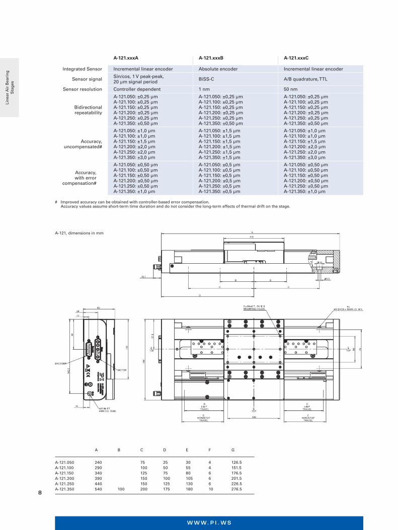
A B C D E F G
A-121.050 A-121.100 A-121.150 A-121.200 A-121.250 A-121.350
240 290 340 390 440 540
100
75 100 125 150 150 200
25 50 75 100 125 175
30 55 80 105 130 180
4 4 6 6 6 10
126.5 151.5 176.5 201.5 226.5 276.5
A-121.xxxA A-121.xxxB A-121.xxxC
Integrated Sensor Incremental linear encoder Absolute encoder Incremental linear encoder
Sensor signal Sin/cos, 1 V peak-peak, 20 µm signal period BiSS-C A/B quadrature, TTL
Sensor resolution Controller dependent 1 nm 50 nm
Bidirectional repeatability
A-121.050: ±0,25 µmA-121.100: ±0,25 µmA-121.150: ±0,25 µmA-121.200: ±0,25 µmA-121.250: ±0,25 µmA-121.350: ±0,50 µm
A-121.050: ±0,25 µmA-121.100: ±0,25 µmA-121.150: ±0,25 µmA-121.200: ±0,25 µmA-121.250: ±0,25 µmA-121.350: ±0,50 µm
A-121.050: ±0,25 µmA-121.100: ±0,25 µmA-121.150: ±0,25 µmA-121.200: ±0,25 µmA-121.250: ±0,25 µmA-121.350: ±0,50 µm
Accuracy, uncompensated#
A-121.050: ±1,0 µmA-121.100: ±1,0 µmA-121.150: ±1,5 µmA-121.200: ±2,0 µmA-121.250: ±2,0 µmA-121.350: ±3,0 µm
A-121.050: ±1,5 µmA-121.100: ±1,5 µmA-121.150: ±1,5 µmA-121.200: ±1,5 µmA-121.250: ±1,5 µmA-121.350: ±1,5 µm
A-121.050: ±1,0 µmA-121.100: ±1,0 µmA-121.150: ±1,5 µmA-121.200: ±2,0 µmA-121.250: ±2,0 µmA-121.350: ±3,0 µm
Accuracy, with error
compensation#
A-121.050: ±0,50 µmA-121.100: ±0,50 µmA-121.150: ±0,50 µmA-121.200: ±0,50 µmA-121.250: ±0,50 µmA-121.350: ±1,0 µm
A-121.050: ±0,5 µmA-121.100: ±0,5 µmA-121.150: ±0,5 µmA-121.200: ±0,5 µmA-121.250: ±0,5 µmA-121.350: ±0,5 µm
A-121.050: ±0,50 µmA-121.100: ±0,50 µmA-121.150: ±0,50 µmA-121.200: ±0,50 µmA-121.250: ±0,50 µmA-121.350: ±1,0 µm
A-121, dimensions in mm
# Improved accuracy can be obtained with controller-based error compensation. Accuracy values assume short-term time duration and do not consider the long-term effects of thermal drift on the stage.
Lin
ear
Air
Bea
rin
g
Sta
ges
M O T I O N | P O S I T I O N I N G
9
Accessories and options
n Encoder
n PIglide filter and air preparation kits
n Single and multi-axis motion controller
n XY setups and individual configurations
n Cable track variations
n Options with counterweight for vertical (Z) orientation
n Customizations available
n Base plates made of granite and systems for reducing vibration
Fields of application
PIglide positioning systems are ideally suited for high-pre- cision application in measuring technology, fiber positioning, semiconductor and flat screen inspection, laser processing, and precision scanning.
Thanks to the friction-free motion, no particles are formed, which makes PIglide stages ideal for cleanroom applications.
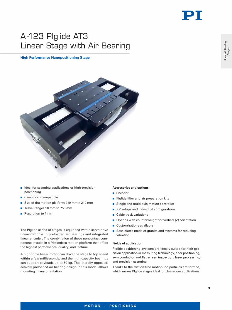
n Ideal for scanning applications or high-precision positioning
n Cleanroom compatible
n Size of the motion platform 210 mm × 210 mm
n Travel ranges 50 mm to 750 mm
n Resolution to 1 nm
The PIglide series of stages is equipped with a servo drive linear motor with preloaded air bearings and integrated linear encoder. The combination of these noncontact com-ponents results in a frictionless motion platform that offers the highest performance, quality, and lifetime.
A high-force linear motor can drive the stage to top speed within a few milliseconds, and the high-capacity bearings can support payloads up to 60 kg. The laterally opposed, actively preloaded air bearing design in this model allows mounting in any orientation.
High Performance Nanopositioning Stage
A-123 PIglide AT3 Linear Stage with Air Bearing
Lin
ear
Air
Bea
rin
g
Sta
ges
W W W. P I . W S
10
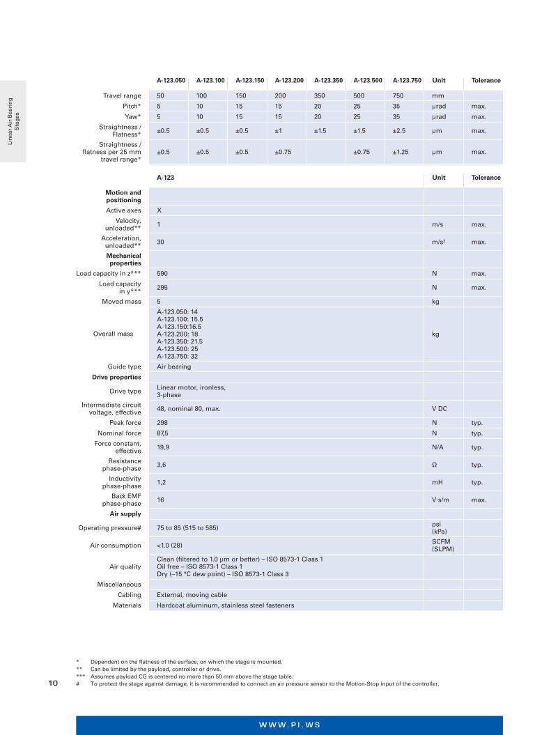
A-123.050 A-123.100 A-123.150 A-123.200 A-123.350 A-123.500 A-123.750 Unit Tolerance
Travel range 50 100 150 200 350 500 750 mm
Pitch* 5 10 15 15 20 25 35 µrad max.
Yaw* 5 10 15 15 20 25 35 µrad max.
Straightness / Flatness* ±0.5 ±0.5 ±0.5 ±1 ±1.5 ±1.5 ±2.5 µm max.
Straightness / flatness per 25 mm
travel range*±0.5 ±0.5 ±0.5 ±0.75 ±0.75 ±1.25 µm max.
A-123 Unit Tolerance
Motion and positioning
Active axes X
Velocity, unloaded** 1 m/s max.
Acceleration, unloaded** 30 m/s² max.
Mechanical properties
Load capacity in z*** 590 N max.
Load capacity in y*** 295 N max.
Moved mass 5 kg
Overall mass
A-123.050: 14A-123.100: 15.5A-123.150:16.5A-123.200: 18A-123.350: 21.5A-123.500: 25A-123.750: 32
kg
Guide type Air bearing
Drive properties
Drive type Linear motor, ironless,3-phase
Intermediate circuit voltage, effective 48, nominal 80, max. V DC
Peak force 298 N typ.
Nominal force 87,5 N typ.
Force constant, effective 19,9 N/A typ.
Resistance phase-phase 3,6 Ω typ.
Inductivity phase-phase 1,2 mH typ.
Back EMF phase-phase 16 V·s/m max.
Air supply
Operating pressure# 75 to 85 (515 to 585) psi (kPa)
Air consumption <1.0 (28) SCFM (SLPM)
Air qualityClean (filtered to 1.0 µm or better) – ISO 8573-1 Class 1Oil free – ISO 8573-1 Class 1Dry (–15 °C dew point) – ISO 8573-1 Class 3
Miscellaneous
Cabling External, moving cable
Materials Hardcoat aluminum, stainless steel fasteners
* Dependent on the flatness of the surface, on which the stage is mounted.** Can be limited by the payload, controller or drive.*** Assumes payload CG is centered no more than 50 mm above the stage table.# To protect the stage against damage, it is recommended to connect an air pressure sensor to the Motion-Stop input of the controller.
Lin
ear
Air
Bea
rin
g
Sta
ges

M O T I O N | P O S I T I O N I N G
11
A-123.xxxA A-123.xxxB A-123.xxxC
Integrated Sensor Incremental linear encoder Absolute encoder Incremental linear encoder
Sensor signal Sin/cos, 1 V peak-peak,20 µm signal period BiSS-C A/B quadrature, TTL
Sensor resolution Controller dependent 1 nm 50 nm
Bidirectional repeatability
A-123.050: ±0.25 µmA-123.100: ±0.25 µmA-123.150: ±0.25 µmA-123.200: ±0.25 µmA-123.350: ±0.5 µmA-123.500: ±0.5 µmA-123.750: ±0.75 µm
A-123.050: ±0.25 µmA-123.100: ±0.25 µmA-123.150: ±0.25 µmA-123.200: ±0.25 µmA-123.350: ±0.5 µmA-123.500: ±0.5 µmA-123.750: ±0.75 µm
A-123.050: ±0.25 µmA-123.100: ±0.25 µmA-123.150: ±0.25 µmA-123.200: ±0.25 µmA-123.350: ±0.5 µmA-123.500: ±0.5 µmA-123.750: ±0.75 µm
Accuracy, uncompensated##
A-123.050: ±1 µmA-123.100: ±1 µmA-123.150: ±1.5 µmA-123.200: ±2 µmA-123.350: ±3 µmA-123.500: ±3.5 µmA-123.750: ±5 µm
A-123.050: ±1.5 µmA-123.100: ±1.5 µmA-123.150: ±1.5 µmA-123.200: ±1.5 µmA-123.350: ±1.5 µmA-123.500: ±1.5 µmA-123.750: ±1.5 µm
A-123.050: ±1 µmA-123.100: ±1 µmA-123.150: ±1.5 µmA-123.200: ±2 µmA-123.350: ±3 µmA-123.500: ±3.5 µmA-123.750: ±5 µm
Accuracy, with error compensation##
A-123.050: ±0.5 µmA-123.100: ±0.5 µmA-123.150: ±0.5 µmA-123.200: ±0.5 µmA-123.350: ±1 µmA-123.500: ±1 µmA-123.750: ±1.5 µm
A-123.050: ±1.5 µmA-123.100: ±1.5 µmA-123.150: ±1.5 µmA-123.200: ±1.5 µmA-123.350: ±1.5 µmA-123.500: ±1.5 µmA-123.750: ±1.5 µm
A-123.050: ±0.5 µmA-123.100: ±0.5 µmA-123.150: ±0.5 µmA-123.200: ±0.5 µmA-123.350: ±1 µmA-123.500: ±1 µmA-123.750: ±1.5 µm
A B* C* D* E* F G Hx J
A-123.050 A-123.100 A-123.150 A-123.200 A-123.350 A-123.500 A-123.750
350 400450 500 650 500 1050
100 100 100 100 100 100
325 300 400
500 700
250 300350 400 550 700 1000
25 5075 100 175 250 375
31.5 56.581.5 106.5 181.5 256.5 381.5
4 8 8 8 12 16 16
181.5 206.5 231.5 256.5 331.5 406.5 531.5
A-123, dimensions in mm
* The mounting holes are symmetric around the center line located at “J”
## Improved accuracy can be obtained with controller-based error compensation. Accuracy values assume short-term time duration and do not consider the long-term effects of thermal drift on the stage.
Lin
ear
Air
Bea
rin
g
Sta
ges
W W W. P I . W S
12
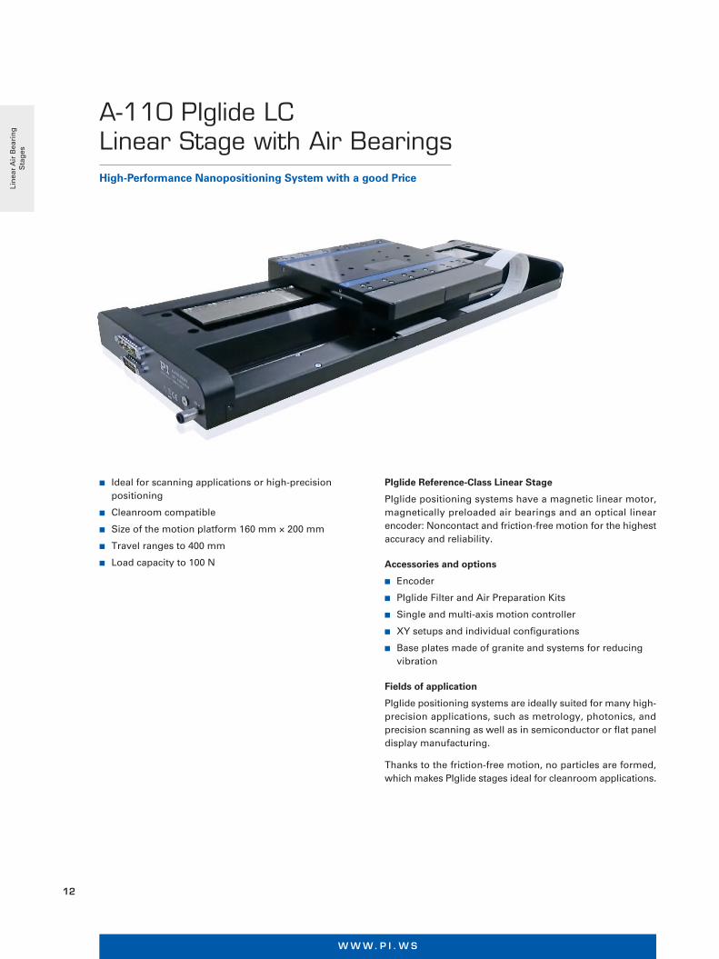
PIglide Reference-Class Linear Stage
PIglide positioning systems have a magnetic linear motor, magnetically preloaded air bearings and an optical linear encoder: Noncontact and friction-free motion for the highest accuracy and reliability.
Accessories and options
n Encoder
n PIglide Filter and Air Preparation Kits
n Single and multi-axis motion controller
n XY setups and individual configurations
n Base plates made of granite and systems for reducing vibration
Fields of application
PIglide positioning systems are ideally suited for many high-precision applications, such as metrology, photonics, and precision scanning as well as in semiconductor or flat panel display manufacturing.
Thanks to the friction-free motion, no particles are formed, which makes PIglide stages ideal for cleanroom applications.
n Ideal for scanning applications or high-precision positioning
n Cleanroom compatible
n Size of the motion platform 160 mm × 200 mm
n Travel ranges to 400 mm
n Load capacity to 100 N
High-Performance Nanopositioning System with a good Price
A-110 PIglide LC Linear Stage with Air Bearings
Lin
ear
Air
Bea
rin
g
Sta
ges
M O T I O N | P O S I T I O N I N G
13
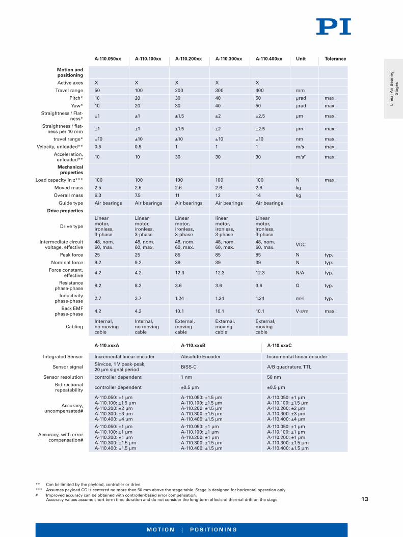
A-110.050xx A-110.100xx A-110.200xx A-110.300xx A-110.400xx Unit Tolerance
Motion and positioning
Active axes X X X X X
Travel range 50 100 200 300 400 mm
Pitch* 10 20 30 40 50 µrad max.
Yaw* 10 20 30 40 50 µrad max.
Straightness / Flat-ness* ±1 ±1 ±1.5 ±2 ±2.5 µm max.
Straightness / flat-ness per 10 mm ±1 ±1 ±1.5 ±2 ±2.5 µm max.
travel range* ±10 ±10 ±10 ±10 ±10 nm max.
Velocity, unloaded** 0.5 0.5 1 1 1 m/s max.
Acceleration, unloaded** 10 10 30 30 30 m/s² max.
Mechanical properties
Load capacity in z*** 100 100 100 100 100 N max.
Moved mass 2.5 2.5 2.6 2.6 2.6 kg
Overall mass 6.3 7.5 11 12 14 kg
Guide type Air bearings Air bearings Air bearings Air bearings Air bearings
Drive properties
Drive type
Linear motor, ironless, 3-phase
Linear motor, ironless, 3-phase
Linear motor, ironless, 3-phase
linear motor, ironless, 3-phase
Linear motor, ironless, 3-phase
Intermediate circuit voltage, effective
48, nom. 60, max.
48, nom. 60, max.
48, nom. 60, max.
48, nom. 60, max.
48, nom. 60, max. VDC
Peak force 25 25 85 85 85 N typ.
Nominal force 9.2 9.2 39 39 39 N typ.
Force constant, effective 4.2 4.2 12.3 12.3 12.3 N/A typ.
Resistance phase-phase 8.2 8.2 3.6 3.6 3.6 Ω typ.
Inductivity phase-phase 2.7 2.7 1.24 1.24 1.24 mH typ.
Back EMF phase-phase 4.2 4.2 10.1 10.1 10.1 V·s/m max.
CablingInternal, no moving cable
Internal, no moving cable
External, moving cable
External, moving cable
External, moving cable
A-110.xxxA A-110.xxxB A-110.xxxC
Integrated Sensor Incremental linear encoder Absolute Encoder Incremental linear encoder
Sensor signal Sin/cos, 1 V peak-peak, 20 µm signal period BiSS-C A/B quadrature, TTL
Sensor resolution controller dependent 1 nm 50 nm
Bidirectional repeatability controller dependent ±0.5 µm ±0.5 µm
Accuracy, uncompensated#
A-110.050: ±1 µm A-110.100: ±1.5 µm A-110.200: ±2 µmA-110.300: ±3 µmA-110.400: ±4 µm
A-110.050: ±1.5 µmA-110.100: ±1.5 µmA-110.200: ±1.5 µmA-110.300: ±1.5 µmA-110.400: ±1.5 µm
A-110.050: ±1 µmA-110.100: ±1.5 µmA-110.200: ±2 µmA-110.300: ±3 µmA-110.400: ±4 µm
Accuracy, with error compensation#
A-110.050: ±1 µmA-110.100: ±1 µmA-110.200: ±1 µmA-110.300: ±1.5 µmA-110.400: ±1.5 µm
A-110.050: ±1 µmA-110.100: ±1 µmA-110.200: ±1 µmA-110.300: ±1.5 µmA-110.400: ±1.5 µm
A-110.050: ±1 µmA-110.100: ±1 µmA-110.200: ±1 µmA-110.300: ±1.5 µmA-110.400: ±1.5 µm
** Can be limited by the payload, controller or drive.*** Assumes payload CG is centered no more than 50 mm above the stage table. Stage is designed for horizontal operation only.# Improved accuracy can be obtained with controller-based error compensation.
Accuracy values assume short-term time duration and do not consider the long-term effects of thermal drift on the stage.
Lin
ear
Air
Bea
rin
g
Sta
ges
W W W. P I . W S
14
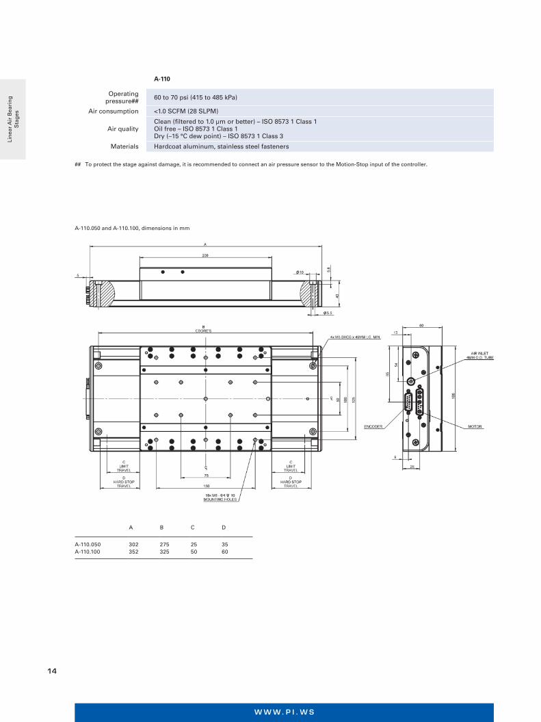
A B C D
A-110.050 A-110.100
302 352
275 325
25 50
35 60
A-110.050 and A-110.100, dimensions in mm
A-110
Operating pressure## 60 to 70 psi (415 to 485 kPa)
Air consumption <1.0 SCFM (28 SLPM)
Air qualityClean (filtered to 1.0 µm or better) – ISO 8573 1 Class 1Oil free – ISO 8573 1 Class 1Dry (–15 °C dew point) – ISO 8573 1 Class 3
Materials Hardcoat aluminum, stainless steel fasteners
## To protect the stage against damage, it is recommended to connect an air pressure sensor to the Motion-Stop input of the controller.
Lin
ear
Air
Bea
rin
g
Sta
ges
M O T I O N | P O S I T I O N I N G
15
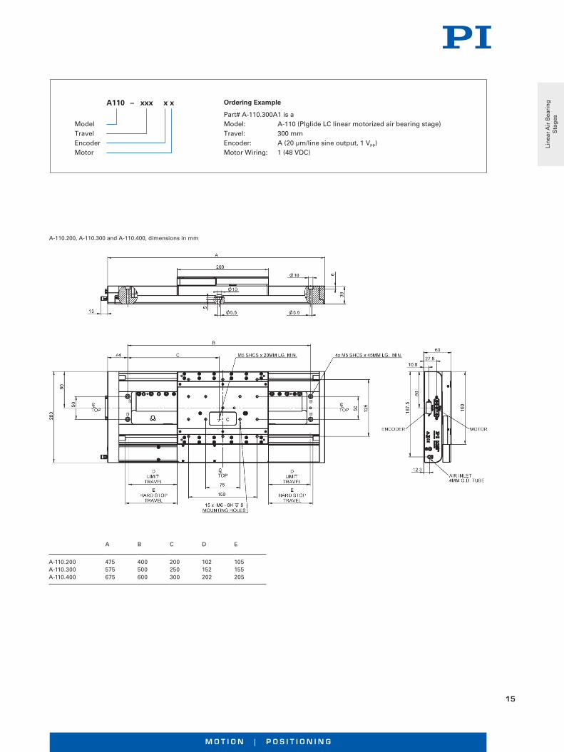
A B C D E
A-110.200 A-110.300 A-110.400
475 575 675
400 500 600
200 250 300
102 152 202
105 155 205
A-110.200, A-110.300 and A-110.400, dimensions in mm
Ordering Example
Part# A-110.300A1 is a Model: A-110 (PIglide LC linear motorized air bearing stage) Travel: 300 mm Encoder: A (20 µm/line sine output, 1 Vpp) Motor Wiring: 1 (48 VDC)
A110 – xxx x x
ModelTravelEncoderMotor
Lin
ear
Air
Bea
rin
g
Sta
ges
W W W. P I . W S
16
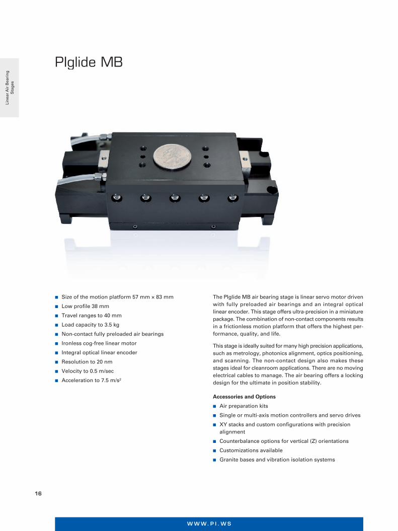
High Performance, Cleanroom Compatible, Customizable
PIglide MB Miniature Linear Air Bearing Stage
n Size of the motion platform 57 mm × 83 mm
n Low profile 38 mm
n Travel ranges to 40 mm
n Load capacity to 3.5 kg
n Non-contact fully preloaded air bearings
n Ironless cog-free linear motor
n Integral optical linear encoder
n Resolution to 20 nm
n Velocity to 0.5 m/sec
n Acceleration to 7.5 m/s²
The PIglide MB air bearing stage is linear servo motor driven with fully preloaded air bearings and an integral optical linear encoder. This stage offers ultra-precision in a miniature package. The combination of non-contact components results in a frictionless motion platform that offers the highest per-formance, quality, and life.
This stage is ideally suited for many high precision applications, such as metrology, photonics alignment, optics positioning, and scanning. The non-contact design also makes these stages ideal for cleanroom applications. There are no moving electrical cables to manage. The air bearing offers a locking design for the ultimate in position stability.
Accessories and Options
n Air preparation kits
n Single or multi-axis motion controllers and servo drives
n XY stacks and custom configurations with precision alignment
n Counterbalance options for vertical (Z) orientations
n Customizations available
n Granite bases and vibration isolation systems
Lin
ear
Air
Bea
rin
g
Sta
ges

M O T I O N | P O S I T I O N I N G
17
A-141.040E1
Travel 40 mm
Drive type Brushless ironless linear servo motor, 3-phase
Feedback system Non-contact optical linear encoder with travel limits and home index
Intermediate circuit voltage, effective 48 VDC nominal, 80 VDC max
Force constant, effective 2.1 N/A
Nominal force 0.58 N
Peak force 2.3 N
Back EMF phase-phase 0.7 V·s/m
Resistance phase-phase 22.4 Ω
Inductivity phase-phase 1.0 mH
Maximum velocity (1) Up to 0.5 m/s
Maximum acceleration (1)
unloaded)
Up to 7.5 m/s²
3.5 kg
Load capacity in z (2) ±2.0 µm
Accuracy (3) (uncompensated) ±0.5 µm
Accuracy (3) (with error
compensation)±0.2 µm
Repeatability 20 nm
Encoder resolution (4) <1µm TIR over full travel
Straightness / flatness (5) <5 µrad over full travel
Pitch / yaw (5) 0.6 kg
Overall mass 0.3 kg
Moving mass Internal, non-moving
Cabling 65±5 psi (450±35 kPa)
Operating pressure (6) <1.0 SCFM (28 SLPM)
Air consumption Clean (filtered to 1.0 µm or better) – ISO 8573-1 Class 1;
Air qualityClean (filtered to 1.0 µm or better) – ISO 8573-1 Class 1; Oil-free – ISO 8573-1 Class 1; Dry (–15 °C dew point) – ISO 8573-1 Class 3
Materials Hardcoat aluminum, stainless steel fasteners
(1) Maximum velocity and acceleration based on unloaded stage capability, may be limited by payload, controller, or drive performance.(2) Assumes payload CG is centered no more than 50mm above the stage table. Stage is designed for horizontal operation only.(3) Improved accuracy can be obtained with controller-based error compensation.
Accuracy values assume short-term time duration and do not consider the long-term effects of thermal drift on the stage.(4) Encoder resolution depends on encoder option chosen. Resolution will impact repeatability specification.(5) Dependent on the flatness of the surface to which the stage is mounted.(6) To protect stage from damage, an under-pressure air sensor tied to the controller E-stop input is recommended.
Lin
ear
Air
Bea
rin
g
Sta
ges
W W W. P I . W S
18
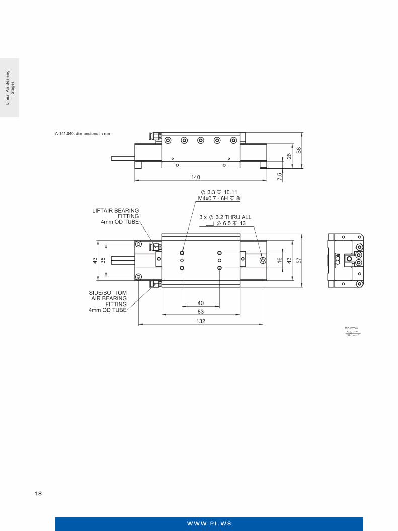
A-141.040, dimensions in mm
Lin
ear
Air
Bea
rin
g
Sta
ges
M O T I O N | P O S I T I O N I N G
19
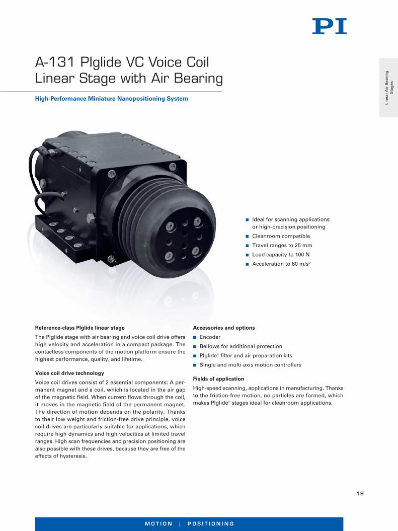
n Ideal for scanning applications or high-precision positioning
n Cleanroom compatible
n Travel ranges to 25 mm
n Load capacity to 100 N
n Acceleration to 80 m/s²
Accessories and options
n Encoder
n Bellows for additional protection
n PIglide® filter and air preparation kits
n Single and multi-axis motion controllers
Fields of application
High-speed scanning, applications in manufacturing. Thanks to the friction-free motion, no particles are formed, which makes PIglide® stages ideal for cleanroom applications.
Reference-class PIglide linear stage
The PIglide stage with air bearing and voice coil drive offers high velocity and acceleration in a compact package. The contactless components of the motion platform ensure the highest performance, quality, and lifetime.
Voice coil drive technology
Voice coil drives consist of 2 essential components: A per-manent magnet and a coil, which is located in the air gap of the magnetic field. When current flows through the coil, it moves in the magnetic field of the permanent magnet. The direction of motion depends on the polarity. Thanks to their low weight and friction-free drive principle, voice coil drives are particularly suitable for applications, which require high dynamics and high velocities at limited travel ranges. High scan frequencies and precision positioning are also possible with these drives, because they are free of the effects of hysteresis.
High-Performance Miniature Nanopositioning System
A-131 PIglide VC Voice Coil Linear Stage with Air Bearing
Lin
ear
Air
Bea
rin
g
Sta
ges
W W W. P I . W S
20
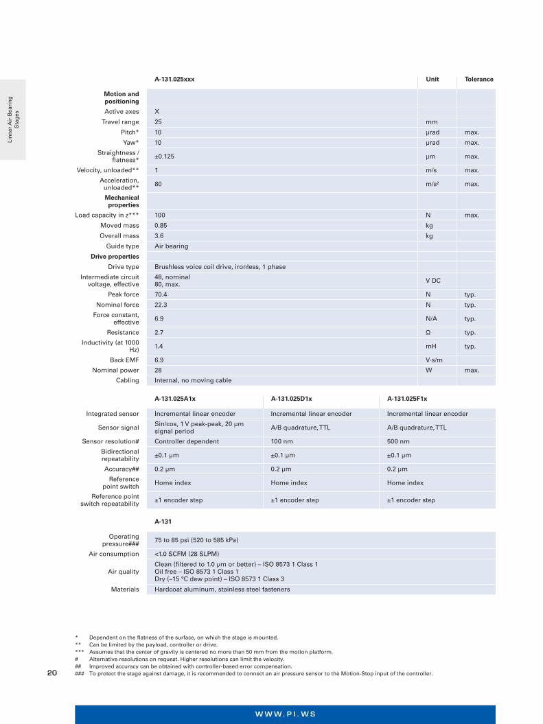
A-131.025xxx Unit Tolerance
Motion and positioning
Active axes X
Travel range 25 mm
Pitch* 10 µrad max.
Yaw* 10 µrad max.
Straightness / flatness* ±0.125 µm max.
Velocity, unloaded** 1 m/s max.
Acceleration, unloaded** 80 m/s² max.
Mechanical properties
Load capacity in z*** 100 N max.
Moved mass 0.85 kg
Overall mass 3.6 kg
Guide type Air bearing
Drive properties
Drive type Brushless voice coil drive, ironless, 1 phase
Intermediate circuit voltage, effective
48, nominal 80, max. V DC
Peak force 70.4 N typ.
Nominal force 22.3 N typ.
Force constant, effective 6.9 N/A typ.
Resistance 2.7 Ω typ.
Inductivity (at 1000 Hz) 1.4 mH typ.
Back EMF 6.9 V·s/m
Nominal power 28 W max.
Cabling Internal, no moving cable
* Dependent on the flatness of the surface, on which the stage is mounted.** Can be limited by the payload, controller or drive.*** Assumes that the center of gravity is centered no more than 50 mm from the motion platform.# Alternative resolutions on request. Higher resolutions can limit the velocity.## Improved accuracy can be obtained with controller-based error compensation.### To protect the stage against damage, it is recommended to connect an air pressure sensor to the Motion-Stop input of the controller.
A-131.025A1x A-131.025D1x A-131.025F1x
Integrated sensor Incremental linear encoder Incremental linear encoder Incremental linear encoder
Sensor signal Sin/cos, 1 V peak-peak, 20 µm signal period A/B quadrature, TTL A/B quadrature, TTL
Sensor resolution# Controller dependent 100 nm 500 nm
Bidirectional repeatability ±0.1 µm ±0.1 µm ±0.1 µm
Accuracy## 0.2 µm 0.2 µm 0.2 µm
Reference point switch Home index Home index Home index
Reference point switch repeatability ±1 encoder step ±1 encoder step ±1 encoder step
A-131
Operating pressure### 75 to 85 psi (520 to 585 kPa)
Air consumption <1.0 SCFM (28 SLPM)
Air qualityClean (filtered to 1.0 µm or better) – ISO 8573 1 Class 1Oil free – ISO 8573 1 Class 1Dry (–15 °C dew point) – ISO 8573 1 Class 3
Materials Hardcoat aluminum, stainless steel fasteners
Lin
ear
Air
Bea
rin
g
Sta
ges

M O T I O N | P O S I T I O N I N G
21
A-131.025xxB, dimensions in mm
A-131.025xx, dimensions in mm
Lin
ear
Air
Bea
rin
g
Sta
ges
W W W. P I . W S
22
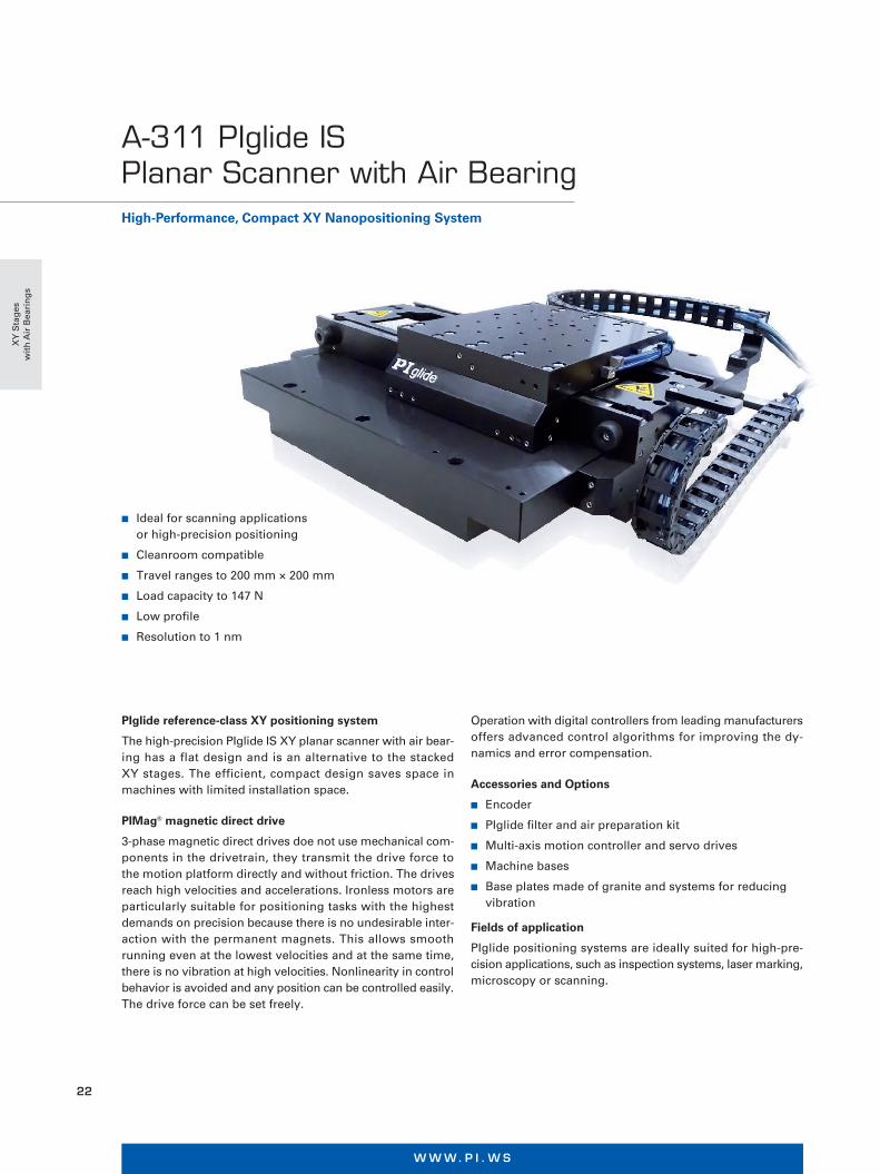
High-Performance, Compact XY Nanopositioning System
A-311 PIglide IS Planar Scanner with Air Bearing
n Ideal for scanning applications or high-precision positioning
n Cleanroom compatible
n Travel ranges to 200 mm × 200 mm
n Load capacity to 147 N
n Low profile
n Resolution to 1 nm
Operation with digital controllers from leading manufacturers offers advanced control algorithms for improving the dy- namics and error compensation.
Accessories and Options
n Encoder
n PIglide filter and air preparation kit
n Multi-axis motion controller and servo drives
n Machine bases
n Base plates made of granite and systems for reducing vibration
Fields of application
PIglide positioning systems are ideally suited for high-pre- cision applications, such as inspection systems, laser marking, microscopy or scanning.
PIglide reference-class XY positioning system
The high-precision PIglide IS XY planar scanner with air bear- ing has a flat design and is an alternative to the stacked XY stages. The efficient, compact design saves space in machines with limited installation space.
PIMag® magnetic direct drive
3-phase magnetic direct drives doe not use mechanical com-ponents in the drivetrain, they transmit the drive force to the motion platform directly and without friction. The drives reach high velocities and accelerations. Ironless motors are particularly suitable for positioning tasks with the highest demands on precision because there is no undesirable inter-action with the permanent magnets. This allows smooth running even at the lowest velocities and at the same time, there is no vibration at high velocities. Nonlinearity in control behavior is avoided and any position can be controlled easily. The drive force can be set freely.
XY
Sta
ges
w
ith
Air
Bea
rin
gs
M O T I O N | P O S I T I O N I N G
23
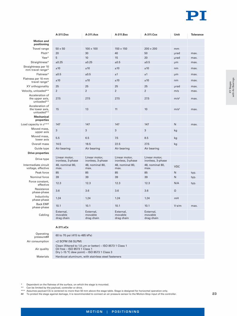
* Dependent on the flatness of the surface, on which the stage is mounted.** Can be limited by the payload, controller or drive.*** Assumes payload CG is centered no more than 50 mm above the stage table. Stage is designed for horizontal operation only.## To protect the stage against damage, it is recommended to connect an air pressure sensor to the Motion-Stop input of the controller.
A-311.Dxx A-311.Axx A-311.Bxx A-311.Cxx Unit Tolerance
Motion and positioning
Travel range 50 × 50 100 × 100 150 × 150 200 × 200 mm
Pitch* 20 30 40 50 µrad max.
Yaw* 5 10 15 20 µrad max.
Straightness* ±0.25 ±0.25 ±0.5 ±0.5 µm max.
Straightness per 10 mm travel range* ±10 ±10 ±10 ±10 nm max.
Flatness* ±0.5 ±0.5 ±1 ±1 µm max.
Flatness per 10 mm travel range* ±10 ±10 ±10 ±10 nm max.
XY orthogonality 25 25 25 25 µrad max.
Velocity, unloaded** 2 2 2 2 m/s max.
Acceleration of the upper axis,
unloaded**27.5 27.5 27.5 27.5 m/s² max.
Acceleration of the lower axis,
unloaded**15 13 11 10 m/s² max.
Mechanical properties
Load capacity in z*** 147 147 147 147 N max.
Moved mass, upper axis 3 3 3 3 kg
Moved mass, lower axis 5.5 6.5 7.5 8.5 kg
Overall mass 14.5 18.5 22.5 27.5 kg
Guide type Air bearing Air bearing Air bearing Air bearing
Drive properties
Drive type Linear motor, ironless, 3-phase
Linear motor, ironless, 3-phase
Linear motor, ironless, 3-phase
Linear motor, ironless, 3-phase
Intermediate circuit voltage, effective
48, nominal 80, max.
48, nominal 80, max.
48, nominal 80, max.
48, nominal 80, max. VDC
Peak force 85 85 85 85 N typ.
Nominal force 39 39 39 39 N typ.
Force constant, effective 12.3 12.3 12.3 12.3 N/A typ.
Resistance phase-phase 3.6 3.6 3.6 3.6 Ω
Inductivity phase-phase 1.24 1.24 1.24 1.24 mH
Back EMF phase-phase 10.1 10.1 10.1 10.1 V·s/m max.
CablingExternal, movable drag chain
External, movable drag chain
External, movable drag chain
External, movable drag chain
A-311.xCx
Operating pressure## 60 to 70 psi (415 to 485 kPa)
Air consumption <2 SCFM (56 SLPM)
Air qualityClean (filtered to 1.0 µm or better) – ISO 8573 1 Class 1 Oil free – ISO 8573 1 Class 1 Dry (–15 °C dew point) – ISO 8573 1 Class 3
Materials Hardcoat aluminum, with stainless steel fasteners
XY
Sta
ges
w
ith
Air
Bea
rin
gs

W W W. P I . W S
24
A-311.xxx, dimensions in mm
A B C D E F
A-311.Dxx A-311.Axx A-311.Bxx A-311.Cxx
300 350 400 450
232 282 332 382
100 150 200 250
275 325 375 425
25 50 75 100
305580105
A-311.xAx A-311.xBx A-311.xCx
Integrated sensor Incremental linear encoder Absolute encoder Incremental linear encoder
Sensor signal Sin/cos, 1 V peak-peak, 20 µm signal period BiSS-C A/B quadrature, TTL
Sensor resolution Controller dependent 1 nm 50 nm
Bidirectional repeatability Controller dependent ±0.05 µm ±0.05 µm
Accuracy, uncompensated#
A-311.Dxx: ±1 µm A-311.Axx: ±1.5 µm A-311.Bxx: ±2 µm A-311.Cxx: ±2.5 µm
A-311.Axx: ±1.5 µm A-311.Axx: ±1.5 µm A-311.Axx: ±1.5 µm A-311.Axx: ±1.5 µm
A-311.Dxx: ±1 µm A-311.Axx: ±1.5 µm A-311.Bxx: ±2 µm A-311.Cxx: ±2.5 µm
Accuracy, with error compensation# ±0.5 µm ±0.5 µm ±0.5 µm
Reference point switch repeatability ±1 encoder step ±1 encoder step ±1 encoder step
# Improved accuracy can be obtained with controller-based error compensation. Accuracy values assume short-term time duration and do not consider the long-term effects of thermal drift on the stage.
XY
Sta
ges
w
ith
Air
Bea
rin
gs

M O T I O N | P O S I T I O N I N G
25
n Ideal for scanning applications or high-precision positioning
n Clean room compatible
n Travel ranges to 500 mm × 1000 mm
n Load capacity to 245 N
n Resolution to 1 nm
n Velocity up to 2 mm/s
Operation with digital controllers from leading manufac- turers offers advanced control algorithms for improving the dynamics and error compensation.
Accessories and options
n PIglide® filter and air preparation kits
n Additional axes
n Machine bases
n Base plates made of granite and systems for reducing vibration
Fields of application
PIglide® positioning systems are ideally suited for many high-precision applications, such as metrology, photonics, and precision scanning as well as in semiconductor or flat panel display manufacturing.
Thanks to the friction-free motion, no particles are formed, which makes PIglide® stages ideal for cleanroom applica-tions.
PIglide® reference-class XY positioning system
The PIglide® HS planar scanner has magnetic linear motors, vacuum preload and absolute encoders: Contact- and fric-tion-free motion for the highest accuracy and reliability.
Absolute encoder
Absolute encoders supply explicit position information that enables immediate determination of the position. This means that referencing is not required during switch-on, which increases efficiency and safety during operation.
PIMag® magnetic direct drive
The stage has an ironless magnetic direct drive, which makes high velocities and acceleration possible. At the same time, sine-commutated control makes high positioning resolution possible because the drive is friction free. The drive force can be set freely.
The positioning system was designed to both maximize the throughput and ensure the highest precision. The flexible coupling of the bridge axis to the gantry axis allows lateral decoupling without sacrificing the stiffness of the system.
XY Positioning System with 1 nm Resolution
A-322 PIglide HS Planar Scanner with Air Bearing
XY
Sta
ges
w
ith
Air
Bea
rin
gs
W W W. P I . W S
26
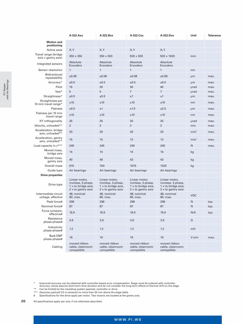
A-322.Axx A-322.Bxx A-322.Cxx A-322.Dxx Unit Tolerance
Motion and positioning
Active axes X, Y X, Y X, Y X, Y
Travel range (bridge axis × gantry axis) 350 × 350 350 × 500 500 × 500 500 × 1000 mm
Integrated sensors Absolute Encoders
Absolute Encoders
Absolute Encoders
Absolute Encoders
Sensor resolution 1 1 1 1 nm
Bidirectional repeatability ±0.08 ±0.08 ±0.08 ±0.08 µm max.
Accuracy* ±0.5 ±0.5 ±0.5 ±0.5 µm max.
Pitch 15 20 30 40 µrad max.
Yaw* 5 5 7 7 µrad max.
Straightness* ±0.5 ±0.5 ±1 ±1 µm max.
Straightness per 10 mm travel range* ±10 ±10 ±10 ±10 nm max.
Flatness ±0.5 ±1 ±1.5 ±2.5 µm max.
Flatness per 10 mm travel range ±10 ±10 ±10 ±10 nm max.
XY orthogonality 25 25 25 25 µrad max.
Velocity, unloaded** 2 2 2 2 m/s max.
Acceleration, bridge axis, unloaded** 20 20 20 20 m/s² max.
Acceleration, gantry axis, unloaded** 15 15 12 12 m/s² max.
Load capacity in z*** 245 245 245 245 N max.
Moved mass, bridge axis 14 14 14 14 kg
Moved mass, gantry axis 40 40 43 43 kg
Overall mass 610 700 1075 1525 kg
Guide type Air bearings Air bearings Air bearings Air bearings
Drive properties
Drive type
Linear motor, ironless, 3-phase, 1 × to bridge axis, 2 × to gantry axis
Linear motor, ironless, 3-phase, 1 × to bridge axis, 2 × to gantry axis
Linear motor, ironless, 3-phase, 1 × to bridge axis, 2 × to gantry axis
Linear motor, ironless, 3-phase, 1 × to bridge axis, 2 × to gantry axis
Intermediate circuit voltage, effective
48, nominal 80, max.
48, nominal 80, max.
48, nominal 80, max.
48, nominal 80, max. VDC
Peak force# 298 298 298 298 N typ.
Nominal force# 87 87 87 87 N typ.
Force constant, effective# 19.9 19.9 19.9 19.9 N/A typ.
Resistance phase-phase# 3.6 3.6 3.6 3.6 Ω
Inductivity phase-phase# 1.2 1.2 1.2 1.2 mH
Back EMF phase-phase# 16 16 16 16 V·s/m max.
Cablingmoved ribbon cable, cleanroom compatible
moved ribbon cable, cleanroom compatible
moved ribbon cable, cleanroom compatible
moved ribbon cable, cleanroom compatible
* Improved accuracy can be obtained with controller-based error compensation. Stage must be ordered with controller. Accuracy values assume short-term time duration and do not consider the long-term effects of thermal drift on the stage.
** Can be limited by the insulating system payload, controller or drive.*** Assumes payload CG is centered no more than 50 mm above the stage table. # Specifications for the drive apply per motor. Two motors are located at the gantry axis. All specifications apply per axis, if not otherwise described.
XY
Sta
ges
w
ith
Air
Bea
rin
gs
M O T I O N | P O S I T I O N I N G
27
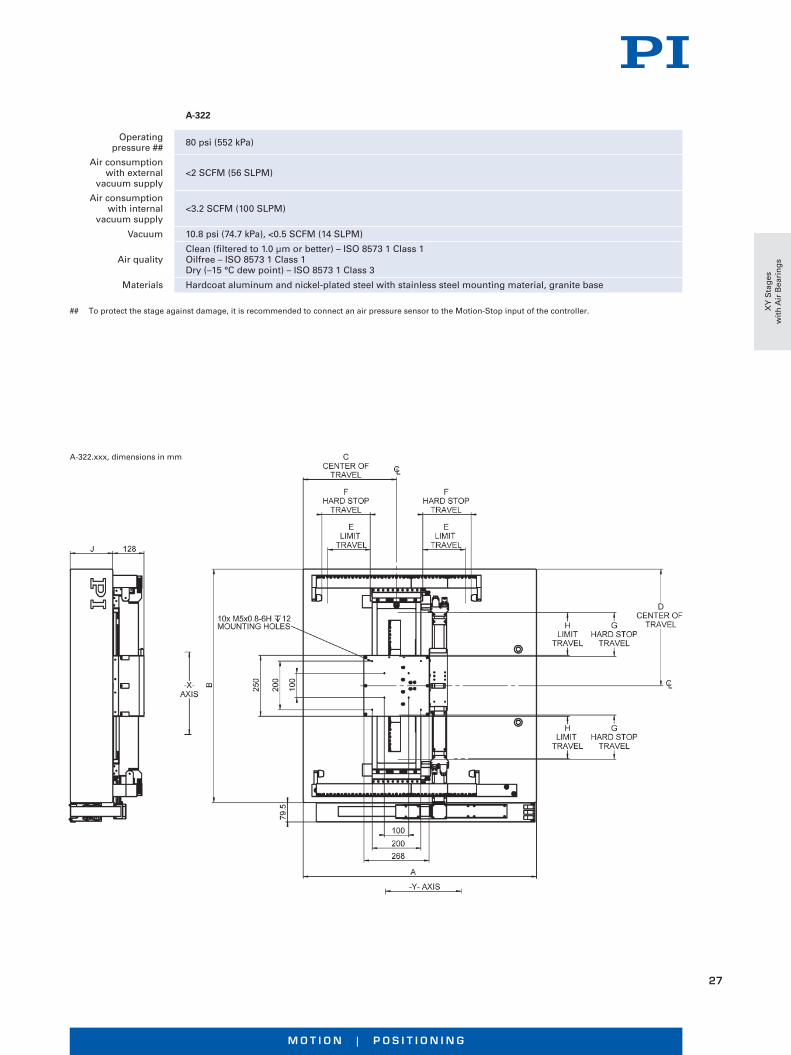
A-322.xxx, dimensions in mm
A-322
Operating pressure ## 80 psi (552 kPa)
Air consumption with external
vacuum supply<2 SCFM (56 SLPM)
Air consumption with internal
vacuum supply<3.2 SCFM (100 SLPM)
Vacuum 10.8 psi (74.7 kPa), <0.5 SCFM (14 SLPM)
Air qualityClean (filtered to 1.0 µm or better) – ISO 8573 1 Class 1Oilfree – ISO 8573 1 Class 1Dry (–15 °C dew point) – ISO 8573 1 Class 3
Materials Hardcoat aluminum and nickel-plated steel with stainless steel mounting material, granite base
## To protect the stage against damage, it is recommended to connect an air pressure sensor to the Motion-Stop input of the controller. XY
Sta
ges
w
ith
Air
Bea
rin
gs

W W W. P I . W S
28
Friction-Free, Ideal for Indexing, Positioning, Scanning, Measuring Technology
A-62x PIglide RM Rotation Stage with Air Bearing
n Cleanroom compatible
n Table diameters from 50 mm to 300 mm
n Load capacity up to 4170 N
n Eccentricity and flatness <200 nm
n Can be mounted vertically or horizontally
Accessories and options
n Encoder
n Optional tip/tilt platform
n Custom mounting flanges
n Vacuum feedthrough
n Slip rings
n PIglide filter and air preparation kit
n Single or multi-axis motion controllers and servo drives
n Base plates made of granite and systems for reducing vibration
Fields of application
Optical adjustment, metrology, inspection systems, calibra- tion, scanning.
PIglide motorized rotation stage
The PIglide RM series of motorized rotation stages are designed for accuracy, precision, high stiffness, and ease of use, and can be mounted in any orientation.
Various options can be combined to create a solution ideal for point-to-point indexing or constant velocity scanning.
The RM stages offer superior runout, flatness, and wobble performance. Because they are friction free and require no maintenance or lubrication, they are ideal for use in clean-rooms.
3-phase torque motor
n Brushless
n Slotless
n Low cogging torque
Absolute encoder (optional)
Absolute encoders supply explicit position information that enables immediate determination of the position. This means that referencing is not required during switch-on, which increases efficiency and safety during operation.
Ro
tati
on
Sta
ges
w
ith
Air
Bea
rin
gs
M O T I O N | P O S I T I O N I N G
29
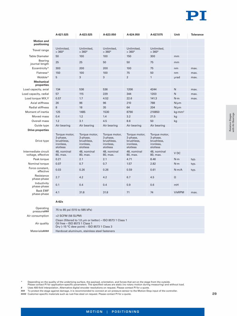
* Depending on the quality of the underlying surface, the payload, orientation, and forces that act on the stage from the outside. Please contact PI for application-specific parameters. The specified values are static (no rotary motion during measuring) and without load.
# Uses 400-fold interpolation. Alternative digital encoder resolutions on request. Please contact PI for a quote. ### To protect the stage against damage, it is recommended to connect an air pressure sensor to the Motion-Stop input of the controller.#### Customer-specific materials such as rust-free steel on request. Please contact PI for a quote.
A-621.025 A-623.025 A-623.050 A-624.050 A-627.075 Unit Tolerance
Motion and positioning
Travel range Unlimited, > 360°
Unlimited, > 360°
Unlimited, > 360°
Unlimited, > 360°
Unlimited, > 360°
Table Diameter 50 100 100 150 300 mm
Bearing journal length 25 25 50 50 75 mm
Eccentricity* 300 200 200 100 75 nm max.
Flatness* 150 100 100 75 50 nm max.
Wobble* 5 3 3 2 1 µrad max.
Mechanical properties
Load capacity, axial 134 536 536 1206 4244 N max.
Load capacity, radial 57 115 229 344 1203 N max.
Load torque MX,Y 0.57 1.7 4.52 22.6 141.3 N·m max.
Axial stiffness 26 96 96 210 788 N/µm
Radial stiffness 8 18 35 64 204 N/µm
Moment of inertia 125 1485 1530 8790 210850 kg·mm²
Moved mass 0.4 1.2 1.4 3.2 21.5 kg
Overall mass 1.2 3.1 4.5 8.6 50 kg
Guide type Air bearing Air bearing Air bearing Air bearing Air bearing
Drive properties
Drive type
Torque motor, 3-phase, brushless, ironless, slotless
Torque motor, 3-phase, brushless, ironless, slotless
Torque motor, 3-phase, brushless, ironless, slotless
Torque motor, 3-phase, brushless, ironless, slotless
Torque motor, 3-phase, brushless, ironless, slotless
Intermediate circuit voltage, effective
48, nominal 80, max.
48, nominal 80, max.
48, nominal 80, max.
48, nominal 80, max.
48, nominal 80, max. V DC
Peak torque 0.21 2.1 2.1 4.71 8.46 N·m typ.
Nominal torque 0.07 0.7 0.7 1.57 2.82 N·m typ.
Force constant, effective 0.03 0.26 0.26 0.59 0.61 N·m/A typ.
Resistance phase-phase 2.7 4.2 4.2 6.7 4.5 Ω
Inductivity phase-phase 0.1 0.4 0.4 0.9 0.6 mH
Back EMF phase-phase 4.1 31.8 31.8 71 74 V/kRPM max.
A-62x
Operating pressure### 75 to 85 psi (515 to 585 kPa)
Air consumption <2 SCFM (56 SLPM)
Air qualityClean (filtered to 1.0 µm or better) – ISO 8573 1 Class 1Oil free – ISO 8573 1 Class 1Dry (–15 °C dew point) – ISO 8573 1 Class 3
Materials#### Hardcoat aluminum, stainless steel fastenersR
ota
tio
n S
tag
es
wit
h A
ir B
eari
ng
s
W W W. P I . W S
30
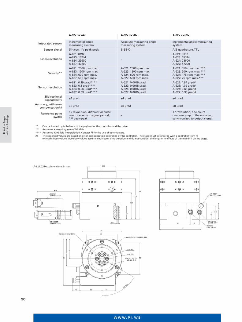
A-62x.xxxAx A-62x.xxxBx A-62x.xxxCx
Integrated sensor Incremental angle measuring system
Absolute-measuring angle measuring system
Incremental angle measuring system
Sensor signal Sin/cos, 1 V peak-peak BiSS-C A/B quadrature, TTL
Lines/revolution
A-621: 8192 A-623: 15744 A-624: 23600 A-627: 47200
–
A-621: 8192 A-623: 15744 A-624: 23600 A-627: 47200
Velocity**
A-621: 2500 rpm max. A-623: 1200 rpm max. A-624: 600 rpm max. A-627: 500 rpm max.
A-621: 2500 rpm max. A-623: 1200 rpm max. A-624: 600 rpm max. A-627: 500 rpm max.
A-621: 550 rpm max.*** A-623: 300 rpm max.*** A-624: 175 rpm max.*** A-627: 75 rpm max.***
Sensor resolution
A-621: 0.19 µrad**** A-623: 0.1 µrad**** A-624: 0.06 µrad**** A-627: 0.03 µrad****
A-621: 0.0015 µrad A-623: 0.0015 µrad A-624: 0.0015 µrad A-627: 0.0015 µrad
A-621: 1.94 µrad# A-623: 1.02 µrad# A-624: 0.68 µrad# A-627: 0.33 µrad#
Bidirectional repeatability ±4 µrad ±4 µrad ±4 µrad
Accuracy, with error compensation## ±8 µrad ±8 µrad ±8 µrad
Reference point switch
1 / revolution, differential pulse over one sensor signal period, 1 V peak-peak
–1 / revolution, one count over one step of the encoder, synchronized to output signal
** Can be limited by imbalance of the payload or the controller and the drive.*** Assumes a sampling rate of 50 MHz.**** Assumes 4096-fold interpolation. Contact PI for the use of other factors.## The specified values are based on error compensation controlled by the controller. The stage must be ordered with a controller from PI
to reach these values. Accuracy values assume short-term time duration and do not consider the long-term effects of thermal drift on the stage.
A-621.025xx, dimensions in mm
Ro
tati
on
Sta
ges
w
ith
Air
Bea
rin
gs
M O T I O N | P O S I T I O N I N G
31
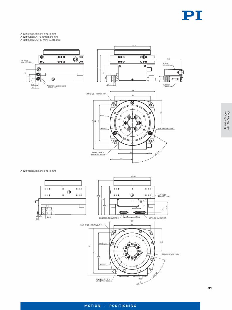
A-623.xxxxx, dimensions in mmA-623.025xx: A=75 mm; B=90 mmA-623.050xx: A=100 mm; B=115 mm
A-624.050xx, dimensions in mm
Ro
tati
on
Sta
ges
w
ith
Air
Bea
rin
gs

W W W. P I . W S
32
A-627.075xx, dimensions in mm
Ro
tati
on
Sta
ges
w
ith
Air
Bea
rin
gs

M O T I O N | P O S I T I O N I N G
33
n Ideal for scanning applications or high-resolution positioning
n Cleanroom compatible
n Size of the motion platform to 300 mm × 300 mm
n Travel ranges to 1 m
n Load capacity to 775 kg
n Straightness / flatness to 0.5 µm per 25 mm
n Pitch / roll / yaw to 1.2 µrad per 25 mm
Linear air bearings of the PIglide RB series are exactly right for applications that need smooth, precise, linear motion. The air bearing modules replace ball or crossed roller guides and are easy to integrate. They offer improved straightness, angular deviation, and repeatability compared to stage units with ball bearings, especially for travel ranges longer than 100 mm.
Because air bearings are basically friction free, they work without stiction on approach or during operation, even under maximum load. Air bearings work without making contact and with purified air, and are virtually maintenance and wear free.
Accessories and options
n Air preparation kit
n Mounting Feet
n Custom configurations on request
n Several motion platforms on one guide
n Constructions with moving guide
Friction Free, Ideal for Positioning, Scanning, Metrology
A-10x PIglide RB Linear Air Bearing Module
Air
Bea
rin
gs
W W W. P I . W S
34
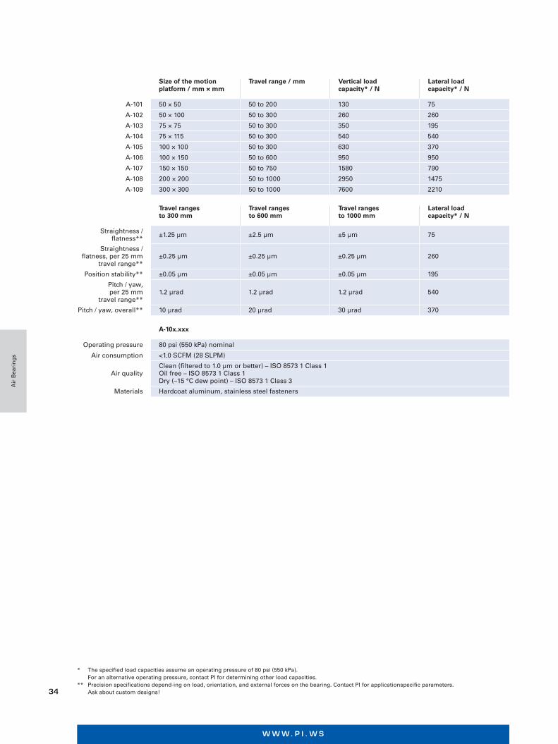
Size of the motion platform / mm × mm
Travel range / mm Vertical load capacity* / N
Lateral load capacity* / N
A-101 50 × 50 50 to 200 130 75
A-102 50 × 100 50 to 300 260 260
A-103 75 × 75 50 to 300 350 195
A-104 75 × 115 50 to 300 540 540
A-105 100 × 100 50 to 300 630 370
A-106 100 × 150 50 to 600 950 950
A-107 150 × 150 50 to 750 1580 790
A-108 200 × 200 50 to 1000 2950 1475
A-109 300 × 300 50 to 1000 7600 2210
Travel ranges to 300 mm
Travel ranges to 600 mm
Travel ranges to 1000 mm
Lateral load capacity* / N
Straightness / flatness** ±1.25 µm ±2.5 µm ±5 µm 75
Straightness /flatness, per 25 mm
travel range**±0.25 µm ±0.25 µm ±0.25 µm 260
Position stability** ±0.05 µm ±0.05 µm ±0.05 µm 195
Pitch / yaw, per 25 mm
travel range**1.2 µrad 1.2 µrad 1.2 µrad 540
Pitch / yaw, overall** 10 µrad 20 µrad 30 µrad 370
A-10x.xxx
Operating pressure 80 psi (550 kPa) nominal
Air consumption <1.0 SCFM (28 SLPM)
Air qualityClean (filtered to 1.0 µm or better) – ISO 8573 1 Class 1 Oil free – ISO 8573 1 Class 1 Dry (–15 °C dew point) – ISO 8573 1 Class 3
Materials Hardcoat aluminum, stainless steel fasteners
* The specified load capacities assume an operating pressure of 80 psi (550 kPa). For an alternative operating pressure, contact PI for determining other load capacities.** Precision specifications depend-ing on load, orientation, and external forces on the bearing. Contact PI for applicationspecific parameters. Ask about custom designs!
Air
Bea
rin
gs
M O T I O N | P O S I T I O N I N G
35
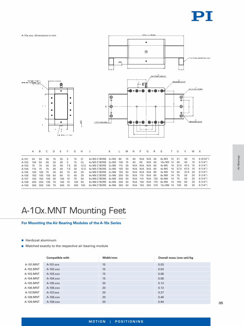
A-10x.xxx, dimensions in mm
A B C D E F G H J K L M N P Q R S T U V W X
A-101 A-102 A-103 A-104 A-105 A-106 A-107 A-108 A-109
50 10075 115100 150150 200 300
50 507575100100150200300
3545557575100100130140
152525453560507070
252545456060100140240
557.57.51010101010
15153030404075100200
ClCL12.512.520205050100
4x M3 C’BORE4x M3 C’BORE4x M5 C’BORE4x M5 C’BORE4x M6 C’BORE4x M6 C’BORE6x M6 C’BORE6x M6 C’BORE6x M6 C’BORE
2x M32x M32x M52x M52x M62x M64x M64x M64x M6
80130115155150200200250350
151535505050505050
4040N/AN/AN/AN/AN/AN/AN/A
N/A60N/AN/AN/A110110150150
N/AN/AN/AN/AN/AN/AN/AN/A250
404060608080125170270
6x M310x M34x M54x M54x M68x M68x M68x M612x M6
121214141414141414
214637.557.5507575100100
304047.567.537.550506565
101015152020202020
4 (5/32”)6 (1/4”)6 (1/4”)6 (1/4”)6 (1/4”)6 (1/4”)6 (1/4”)6 (1/4”)6 (1/4”)
n Hardcoat aluminum
n Matched exactly to the respective air bearing module
Compatible with Width/mm Overall mass (one set)/kg
A-101.MNT A-101.xxx 10 0.03
A-102.MNT A-102.xxx 10 0.03
A-103.MNT A-103.xxx 15 0.08
A-104.MNT A-104.xxx 15 0.08
A-105.MNT A-105.xxx 20 0.13
A-106.MNT A-106.xxx 20 0.13
A-107.MNT A-107.xxx 20 0.27
A-108.MNT A-108.xxx 20 0.46
A-109.MNT A-109.xxx 20 0.94
For Mounting the Air Bearing Modules of the A-10x Series
A-10x.MNT Mounting Feet
Air
Bea
rin
gs
W W W. P I . W S
36
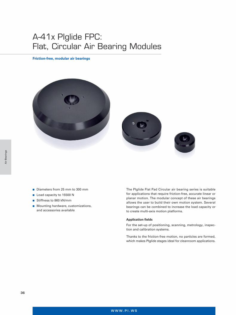
n Diameters from 25 mm to 300 mm
n Load capacity to 15500 N
n Stiffness to 860 kN/mm
n Mounting hardware, customizations, and accessories available
Friction-free, modular air bearings
A-41x PIglide FPC: Flat, Circular Air Bearing Modules
The PIglide Flat Pad Circular air bearing series is suitable for applications that require friction-free, accurate linear or planar motion. The modular concept of these air bearings allows the user to build their own motion system. Several bearings can be combined to increase the load capacity or to create multi-axis motion platforms.
Application fields
For the set-up of positioning, scanning, metrology, inspec-tion and calibration systems.
Thanks to the friction-free motion, no particles are formed, which makes PIglide stages ideal for cleanroom applications.
Air
Bea
rin
gs

M O T I O N | P O S I T I O N I N G
37
Part # Diameter/mm
Ball interface diameter/mm
Load capacity/N
Stiffness/ N/µm
Air consumption/ l/h (SCFH)
Mass/g
A-411.025 25 13 88 17.5 60 (2) 16
A-411.040 40 13 220 28.0 60 (2) 42
A-411.050 50 13 330 52.5 85 (3) 66
A-411.065 65 13 660 78.8 115 (4) 171
A-411.080 80 13 1010 111 170 (6) 259
A-411.100 100 20 1710 175 170 (6) 505
Air supply
Operating pressure 80 psi (550 kPa) nominal
Air qualityClean (filtered to 1.0 µm or better) – ISO 8573 1 Class 1 Oil free – ISO 8573 1 Class 1 Dry (–15 °C dew point) – ISO 8573 1 Class 3
Miscellaneous
Guideway surface flatness <1 µm/300 mm
Nominal fly-height 10-15 µm
Materials Hardcoat aluminum, stainless steel fasteners
Recommended guideway materials
Guideways are supplied by the customer. Granite, hardcoat aluminum, stainless steel, ceramics, nickel-plated steel, nickel-plated cast iron
Air bearing type Discrete orifice
Mounting Hardware (sold separately)
Part # Description Ball interface diameter
A-412.013S Threaded ball stud assembly 13
A-412.013N Mounting nut 13
A-412.013P Retaining plate 13
A-412.020S Threaded ball stud assembly 20
A-412.020N Mounting nut 20
A-412.020P Retaining plate 20
The loads listed assume a supply pressure of 550 kPa (80 psi). Please contact PI if other pressures are required.
Air
Bea
rin
gs
W W W. P I . W S
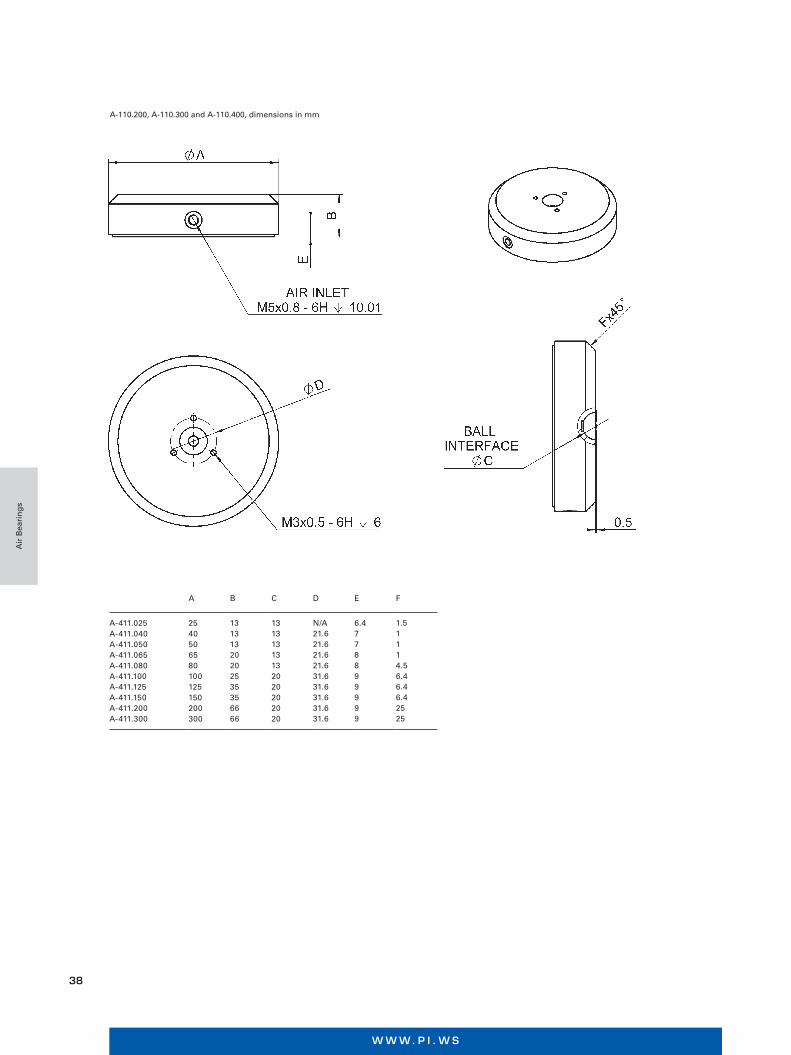
38
A B C D E F
A-411.025A-411.040A-411.050A-411.065A-411.080A-411.100A-411.125A-411.150A-411.200A-411.300
2540506580100125150200300
13131320202535356666
13131313132020202020
N/A21.621.621.621.631.631.631.631.631.6
6.4778899999
1.51114.56.46.46.42525
A-110.200, A-110.300 and A-110.400, dimensions in mm
Air
Bea
rin
gs
M O T I O N | P O S I T I O N I N G
39
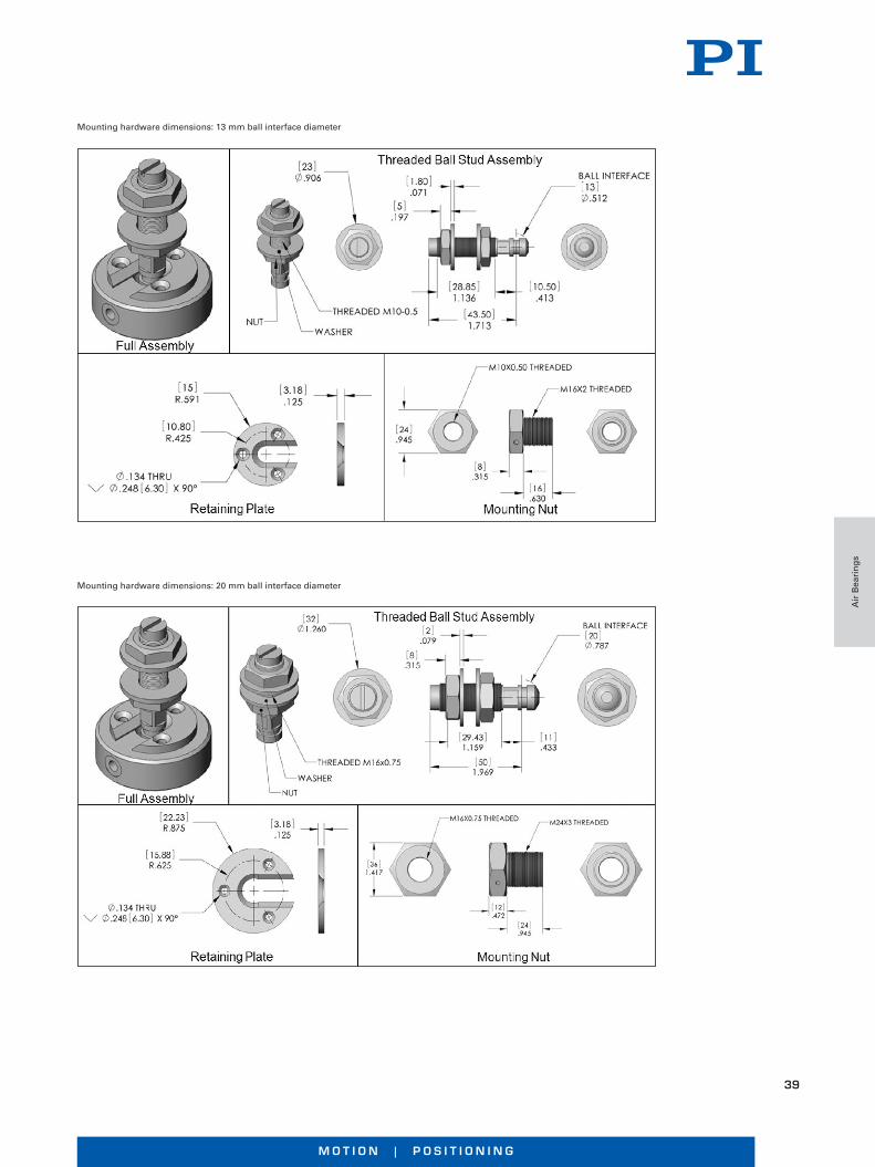
Mounting hardware dimensions: 13 mm ball interface diameter
Mounting hardware dimensions: 20 mm ball interface diameter
Air
Bea
rin
gs
W W W. P I . W S
40
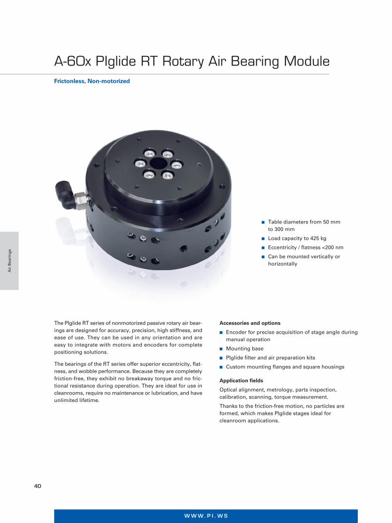
n Table diameters from 50 mm to 300 mm
n Load capacity to 425 kg
n Eccentricity / flatness <200 nm
n Can be mounted vertically or horizontally
The PIglide RT series of nonmotorized passive rotary air bear- ings are designed for accuracy, precision, high stiffness, and ease of use. They can be used in any orientation and are easy to integrate with motors and encoders for complete positioning solutions.
The bearings of the RT series offer superior eccentricity, flat-ness, and wobble performance. Because they are completely friction-free, they exhibit no breakaway torque and no fric-tional resistance during operation. They are ideal for use in cleanrooms, require no maintenance or lubrication, and have unlimited lifetime.
Accessories and options
n Encoder for precise acquisition of stage angle during manual operation
n Mounting base
n PIglide filter and air preparation kits
n Custom mounting flanges and square housings
Application fields
Optical alignment, metrology, parts inspection, calibration, scanning, torque measurement.
Thanks to the friction-free motion, no particles are formed, which makes PIglide stages ideal for cleanroom applications.
Frictonless, Non-motorized
A-60x PIglide RT Rotary Air Bearing Module
Air
Bea
rin
gs
M O T I O N | P O S I T I O N I N G
41
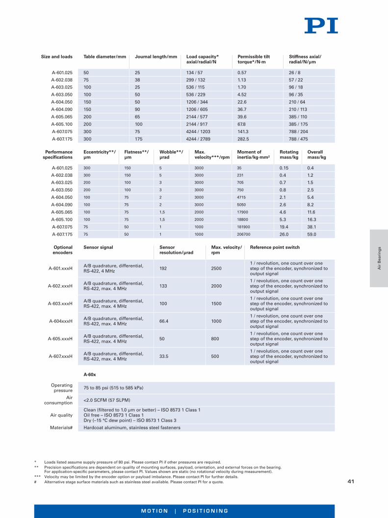
Size and loads Table diameter/mm Journal length/mm Load capacity* axial/radial/N
Permissible tilt torque*/N·m
Stiffness axial/ radial/N/µm
A-601.025 50 25 134 / 57 0.57 26 / 8
A-602.038 75 38 299 / 132 1.13 57 / 22
A-603.025 100 25 536 / 115 1.70 96 / 18
A-603.050 100 50 536 / 229 4.52 96 / 35
A-604.050 150 50 1206 / 344 22.6 210 / 64
A-604.090 150 90 1206 / 605 36.7 210 / 113
A-605.065 200 65 2144 / 577 39.6 385 / 110
A-605.100 200 100 2144 / 917 67.8 385 / 175
A-607.075 300 75 4244 / 1203 141.3 788 / 204
A-607.175 300 175 4244 / 2789 282.5 788 / 475
Optional encoders
Sensor signal Sensor resolution/µrad
Max. velocity/ rpm
Reference point switch
A-601.xxxH A/B quadrature, differential, RS-422, 4 MHz 192 2500
1 / revolution, one count over one step of the encoder, synchronized to output signal
A-602.xxxH A/B quadrature, differential, RS-422, max. 4 MHz 133 2000
1 / revolution, one count over one step of the encoder, synchronized to output signal
A-603.xxxH A/B quadrature, differential, RS-422, max. 4 MHz 100 1500
1 / revolution, one count over one step of the encoder, synchronized to output signal
A-604xxxH A/B quadrature, differential, RS-422, max. 4 MHz 66.4 1000
1 / revolution, one count over one step of the encoder, synchronized to output signal
A-605.xxxH A/B quadrature, differential, RS-422, max. 4 MHz 50 800
1 / revolution, one count over one step of the encoder, synchronized to output signal
A-607.xxxH A/B quadrature, differential, RS-422, max. 4 MHz 33.5 500
1 / revolution, one count over one step of the encoder, synchronized to output signal
Performance specifications
Eccentricity**/ µm
Flatness**/ µm
Wobble**/ µrad
Max. velocity***/rpm
Moment of inertia/kg·mm²
Rotating mass/kg
Overall mass/kg
A-601.025 300 150 5 3000 35 0.15 0.4
A-602.038 300 150 5 3000 231 0.4 1.2
A-603.025 200 100 3 3000 705 0.7 1.5
A-603.050 200 100 3 3000 750 0.8 2.5
A-604.050 100 75 2 3000 4715 2.1 5.4
A-604.090 100 75 2 3000 5050 2.6 8.2
A-605.065 100 75 1,5 2000 17900 4.6 11.6
A-605.100 100 75 1,5 2000 18800 5.3 16.3
A-607.075 75 50 1 1000 181900 19.4 38.1
A-607.175 75 50 1 1000 206700 26.0 59.0
* Loads listed assume supply pressure of 80 psi. Please contact PI if other pressures are required. ** Precision specifications are dependent on quality of mounting surfaces, payload, orientation, and external forces on the bearing. For application-specific parameters, please contact PI. Values shown are static (no rotational velocity during measurement).*** Velocity may be limited by the encoder option or payload imbalance. Please contact PI for further details.# Alternative stage surface materials such as stainless steel available. Please contact PI for a quote.
A-60x
Operating pressure 75 to 85 psi (515 to 585 kPa)
Air consumption <2.0 SCFM (57 SLPM)
Air qualityClean (filtered to 1.0 µm or better) – ISO 8573 1 Class 1 Oil free – ISO 8573 1 Class 1Dry (–15 °C dew point) – ISO 8573 1 Class 3
Materials# Hardcoat aluminum, stainless steel fasteners
Air
Bea
rin
gs

W W W. P I . W S
42
A B C D E F G H J K L M N
A-601.025A-602.038A-603.025A-603.050A-604.050A-604.090A-605.065A-605.100A-607.075A-607.175
5075100100150150200200300300
2538255050906510075175
5065558095135125160150250
70100125125185185240240355355
253050507575100100150150
40507575125125150150250250
6087.5112.5112.5170170220220330330
812.52525404060607575
M3x0.5, 6 DEEPM3x0.5, 6 DEEPM4x0.7, 8 DEEPM4x0.7, 8 DEEPM5x0.8, 10 DEEPM5x0.8, 10 DEEPM6x1.0, 12 DEEPM6x1.0, 12 DEEPM6x1.0, 12 DEEPM6x1.0, 12 DEEP
3x M3 SHCS, 30 LG. MIN 3x M4 SHCS, 40 LG. MIN 3x MS SHCS, 30 LG. MIN 3x MS SHCS, 50 LG. MIN 4x M6 SHCS, 50 LG. MIN 4x M6 SHCS, 90 LG. MIN 6x M6 SHCS, 70 LG. MIN6x M6 SHCS, 100 LG. MIN6x MS SHCS, 80 LG. MIN6x MS SHCS, 150 LG. MIN
3x M3x0.5, 6 DEEP3x M4x0.7, 8 DEEP3x M5x0.8, 10 DEEP3x M5x0.8, 10 DEEP4x M6x1 .0, 12 DEEP4x M6x1.0, 12 DEEP6x M6x1 .0, 12 DEEP6x M6x1 .0, 12 DEEP6x M8x1.25, 16 DEEP6x M8x1.25, 16 DEEP
69.5612.512.522.51623.517.358.5
3030303068685555
A-60x.xxx, dimensions in mm
Air
Bea
rin
gs

M O T I O N | P O S I T I O N I N G
43
A B C D E F G H I
A-601.025 M or HA-602.038 M or HA-603.025 M or HA-603.050 M or HA-604.050 M or HA-604.090 M or HA-605.065 M or HA-605.100 M or HA-607.075 M or HA-607 175 M or H
5075100100150150200200300300
65806590100140130165155255
26.526.5252527.527.5353542.542.5
82106135135185185240240355355
74104125125185185240240355355
5580100100150150200200300300
70100--------
70100--------
M3 SHCS, 25 LG. MIN M4 SHCS, 30 LG. MINM5 SHCS, 25 LG. MINM5 SHCS, 25 LG. MINM5 SHCS, 30 LG. MINM5 SHCS. 30 LG. MINM6 SHCS, 35 LG. MINM6 SHCS, 35 LG. MINMB SHCS, 40 LG. MINMB SHCS, 40 LG MIN
A-60x.xxxH and A-60x.xxxM, dimensions in mm
Air
Bea
rin
gs
W W W. P I . W S
44
Overview
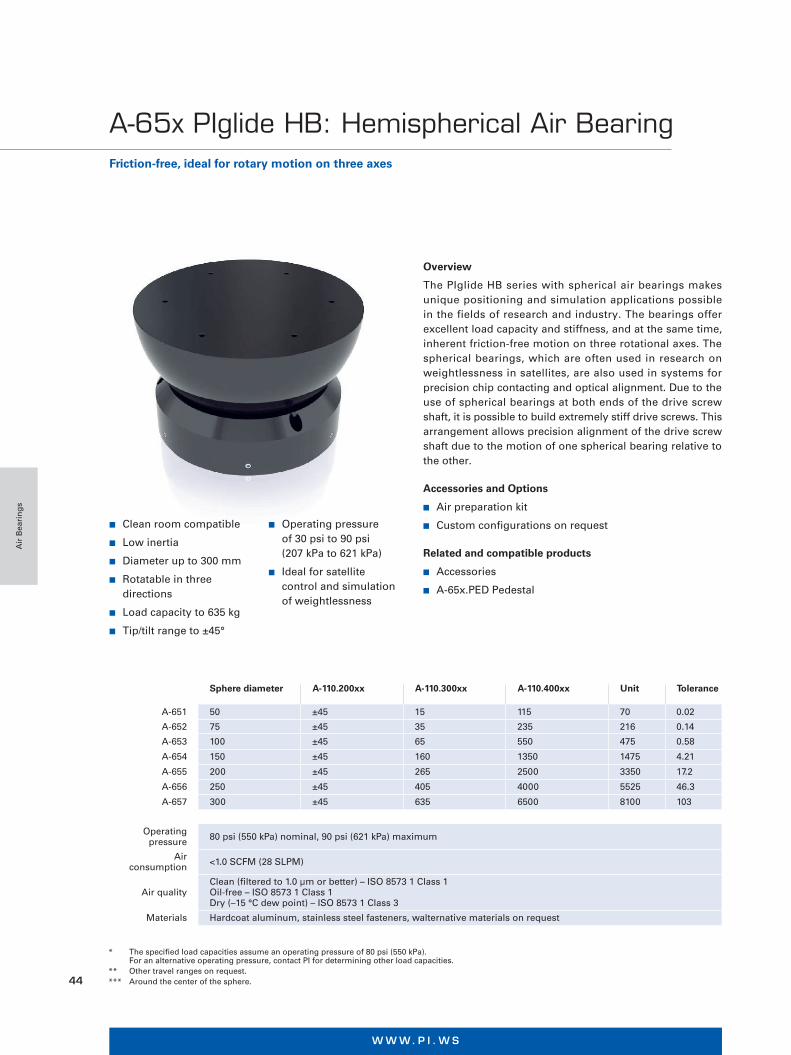
The PIglide HB series with spherical air bearings makes unique positioning and simulation applications possible in the fields of research and industry. The bearings offer excellent load capacity and stiffness, and at the same time, inherent friction-free motion on three rotational axes. The spherical bearings, which are often used in research on weightlessness in satellites, are also used in systems for precision chip contacting and optical alignment. Due to the use of spherical bearings at both ends of the drive screw shaft, it is possible to build extremely stiff drive screws. This arrangement allows precision alignment of the drive screw shaft due to the motion of one spherical bearing relative to the other.
Accessories and Options
n Air preparation kit
n Custom configurations on request
Related and compatible products
n Accessories
n A-65x.PED Pedestal
Sphere diameter A-110.200xx A-110.300xx A-110.400xx Unit Tolerance
A-651 50 ±45 15 115 70 0.02
A-652 75 ±45 35 235 216 0.14
A-653 100 ±45 65 550 475 0.58
A-654 150 ±45 160 1350 1475 4.21
A-655 200 ±45 265 2500 3350 17.2
A-656 250 ±45 405 4000 5525 46.3
A-657 300 ±45 635 6500 8100 103
Operating pressure 80 psi (550 kPa) nominal, 90 psi (621 kPa) maximum
Air consumption <1.0 SCFM (28 SLPM)
Air qualityClean (filtered to 1.0 µm or better) – ISO 8573 1 Class 1 Oil-free – ISO 8573 1 Class 1 Dry (–15 °C dew point) – ISO 8573 1 Class 3
Materials Hardcoat aluminum, stainless steel fasteners, walternative materials on request
* The specified load capacities assume an operating pressure of 80 psi (550 kPa). For an alternative operating pressure, contact PI for determining other load capacities.
** Other travel ranges on request.*** Around the center of the sphere.
Friction-free, ideal for rotary motion on three axes
A-65x PIglide HB: Hemispherical Air Bearing
n Clean room compatible
n Low inertia
n Diameter up to 300 mm
n Rotatable in three directions
n Load capacity to 635 kg
n Tip/tilt range to ±45°
n Operating pressure of 30 psi to 90 psi (207 kPa to 621 kPa)
n Ideal for satellite control and simulation of weightlessness
Air
Bea
rin
gs
M O T I O N | P O S I T I O N I N G
45
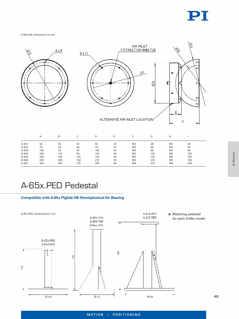
A B C D E F G H I
A-651A-652A-653A-654A-655A-656A-657
5075100150200250300
305070110150200250
42557095125150175
5570100140170210250
23273040505565
M3M3M4M5M5M6M6
386085125175225275
M3M3M4M5M5M6M6
456085125150190230
A-65x.045, dimensions in mm
n Matching pedestal for each A-65x model
A-65x.PED, dimensions in mm
Compatible with A-65x PIglide HB Hemispherical Air Bearing
A-65x.PED Pedestal
Air
Bea
rin
gs
W W W. P I . W S
46
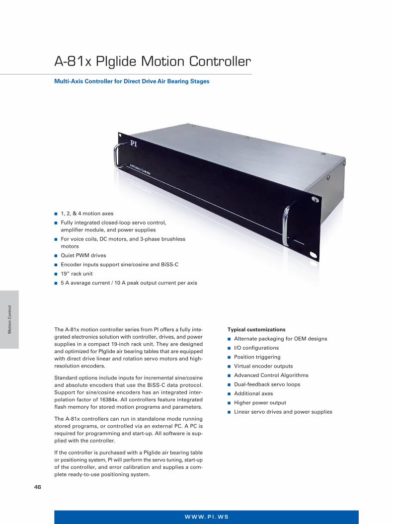
n 1, 2, & 4 motion axes
n Fully integrated closed-loop servo control, amplifier module, and power supplies
n For voice coils, DC motors, and 3-phase brushless motors
n Quiet PWM drives
n Encoder inputs support sine/cosine and BiSS-C
n 19” rack unit
n 5 A average current / 10 A peak output current per axis
The A-81x motion controller series from PI offers a fully inte-grated electronics solution with controller, drives, and power supplies in a compact 19-inch rack unit. They are designed and optimized for PIglide air bearing tables that are equipped with direct drive linear and rotation servo motors and high-resolution encoders.
Standard options include inputs for incremental sine/cosine and absolute encoders that use the BiSS-C data protocol. Support for sine/cosine encoders has an integrated inter- polation factor of 16384x. All controllers feature integrated flash memory for stored motion programs and parameters.
The A-81x controllers can run in standalone mode running stored programs, or controlled via an external PC. A PC is required for programming and start-up. All software is sup-plied with the controller.
If the controller is purchased with a PIglide air bearing table or positioning system, PI will perform the servo tuning, start-up of the controller, and error calibration and supplies a com-plete ready-to-use positioning system.
Typical customizations
n Alternate packaging for OEM designs
n I/O configurations
n Position triggering
n Virtual encoder outputs
n Advanced Control Algorithms
n Dual-feedback servo loops
n Additional axes
n Higher power output
n Linear servo drives and power supplies
Multi-Axis Controller for Direct Drive Air Bearing Stages
A-81x PIglide Motion Controller
Mo
tio
n C
on
tro
l

M O T I O N | P O S I T I O N I N G
47
A-811.23x00 A-812.21x00 A-814.21x00
Number of axes 1 2 4
Controller typeClosed loop servo control (PID) with parameter changing during operation
Closed loop servo control (PID) with parameter changing during operation
Closed loop servo control (PID) with parameter changing during operation
Servo-frequency position control 10 kHz 10 kHz 10 kHz
Servo frequency current control 20 kHz 20 kHz 20 kHz
Trajectory profile modes Point-to-point, jog
Point-to-point, jog, S-curve, interpolated coordinated multi-axis
Point-to-point, jog, S-curve, interpolated coordinated multi-axis
Cooling Fan on the side, continuous operation, constant speed
Fan on the side, continuous operation, constant speed
Fan on the side, continuous operation, constant speed
Drive type PWM PWM PWM
Encoder options (factory configured)
Incremental sine / cosine (1 Vp-p), Absolute, BiSS-C
Incremental sine / cosine (1 Vp-p), A/B quadrature (RS-422) Absolute, BiSS-C
Incremental sine / cosine (1 Vp-p), A/B quadrature (RS-422) Absolute, BiSS-C
Interpolation factor (Sine encoder
options)Up to 16384x Up to 16384x Up to 16384x
Motor output voltage 60 V DC 60 V DC 60 V DC
Motor typesVoice coil, DC motor, 3-phase brushless servo motor with encoder-based sine commutation
Voice coil, DC motor, 3-phase brushless servo motor with encoder-based sine commutation
Voice coil, DC motor, 3-phase brushless servo motor with encoder-based sine commutation
Output current (per axis)
5 A continuous operation, 10 A peak
5 A continuous operation, 10 A peak
5 A continuous operation, 10 A peak
Power supply 120240 V AC, single phase, 50-60 Hz (factory configured)
120-240 V AC, single phase, 50-60 Hz (factory configured)
120-240 V AC, single phase, 50-60 Hz (factory configured)
User I/O (Without reference and limit
switch)
4x digital input, 24 V DC, sink 4x digital output, 24 V DC, sink 1x analog input, differential, ±10 V DC, 12 bit
2x digital input, 24 V DC, sink 2x digital output, 24 V DC, source 1x analog input, differen-tial, ±10 V DC, 12 bit 1x analog output, differential, ±10 VDC, 10 bit 2x RS-422 high-speed output for position trigger (PEG)
4x digital input, 24 V DC, sink 4x digital output, 24 V DC, source 2x analog input, differen-tial, ±10 V DC, 12 bit 2x analog output, differential, ±10 V DC, 10 bit 4x RS-422 high-speed output for position trigger (PEG)
Communication USB 2.0 or TCP/IP TCP/IP TCP/IP
Interlock / Motion-Stop 1x24 V DC 1x24 V DC 1x24 V DC
Connector interface
Rear panel connectors Sub-D for motor and signal connections IEC 60320 type C14 for power supply
Rear panel connectors Sub-D for motor and signal connections IEC 60320 type C14 for power supply
Rear panel connectors Sub-D for motor and signal connections IEC 60320 type C14 for power supply
Mass (approx.) 7.3 kg 8.5 kg 9.3 kg
A-81x, dimensions in mm
Mo
tio
n C
on
tro
l

W W W. P I . W S
48
n Functional safety
n Communication via fieldbus interfaces
n Autotuning
n Synchronization of the individual axes in the system
n Multidimensional motion profiles
n 3-DOF compensation of the position error
n Yaw compensation for gantry solutions
n Suppression of system oscillation
n Robust control behavior
n Easy integration into the higher-level automation environment
SMARTER MOTION AND POSITIONING What makes a positioner and motion solu-tion smart? What functions and features must a high-performance control solution offer to make smart motion and position-ing possible? PI has identified the follow-ing list of basic requirements that make it possible to offer solutions for industrial applications that fulfill the high demands for precision and dynamics irrespective of the number of motion axes.
Positioning and motion tasks in industrial automation such as those in assembly, semiconductor manufac-turing, mechanical engineering, laser material processing, inspection systems or in additive manufacturing demand solutions that need to be robust and reliable. Submicrometer accuracy, exact position reproducibility, high dynamics, and throughput are just as essential. This is particularly the case with industry 4.0 where safety and simple networking options play an important role.
Solutions for Motion Centric Industrial Automation
Mo
tio
n C
on
tro
l

M O T I O N | P O S I T I O N I N G
49
UDMntSPiiPlusEC
HIGH-PERFORMANCE MOTION CONTROL SYSTEMSACS Motion Control offers distributed-architecture motion control systems, completely modular, with compo-nents organized over three levels: The first level is the user interface. This is basically the host software and allows communication with the motion system.
The devices on the second level are called motion controllers. The motion controller is responsible for com-munication with the host software and also takes care of everything related to profile generation, trajectory, macros, diagnostics, and so on. The position commands are sent to the universal drive modules on the third level via an EtherCAT real-time network. In some products, the motion controller, the drives, and the power supplies are integrated into one housing. These products are called control modules.
The universal drive modules on the third level include the digital servo processor (DSP). It performs the servo positioning of the axes. The drive modules power and actuate the motors, handle the feedback devices, manage the I/Os, and analyze the sensor signals for closed-loop positioning control.
COMPLETE SOLUTIONS FOR HIGH-THROUGHPUT AND HIGH-PRECISION MULTI-AXIS APPLICATIONS
Those requirements can only be fulfilled when the mechanics, drive technology, and control electronics of the positioning system are perfectly matched to each other.
A solution from a single-source supplier does not just offer the customer sophisticated positioning technology and high-performance control solutions, but also faster start-up and high flexibility when implementing new requirements.
Mo
tio
n C
on
tro
l
W W W. P I . W S
50
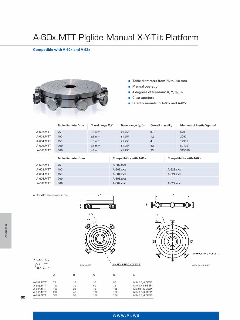
n Table diameters from 75 to 300 mm
n Manual operation
n 4 degrees of freedom: X, Y, θX, θY
n Clear aperture
n Directly mounts to A-60x and A-62x
Table diameter/mm Travel range X,Y Travel range θX, θY Overall mass/kg Moment of inertia/kg·mm²
A-602.MTT 75 ±3 mm ±1,25° 0,8 620
A-603.MTT 100 ±3 mm ±1,25° 1,5 2090
A-604.MTT 150 ±3 mm ±1,25° 4 12900
A-605.MTT 200 ±3 mm ±1,25° 8,6 52100
A-607.MTT 300 ±3 mm ±1,25° 25 319000
Table diameter /mm Compatibility with A-60x Compatibility with A-62x
A-602.MTT 75 A-602.xxx
A-603.MTT 100 A-603.xxx A-623.xxx
A-604.MTT 150 A-604.xxx A-624.xxx
A-605.MTT 200 A-605.xxx
A-607.MTT 300 A-607.xxx A-627.xxx
A B C D E
A-602.MTTA-603.MTTA-604.MTTA-605.MTTA-607.MTT
75 100 150 200 300
25 30 35 45 55
30 50 75 100 150
50 75 125 150 250
M3x0.5, 6 DEEP M4x0.7, 8 DEEP M5x0.8, 10 DEEP M6x0.5, 6 DEEP M3x0.5, 6 DEEP
Compatible with A-60x and A-62x
A-60x.MTT PIglide Manual X-Y-Tilt Platform
A-60x.MTT, dimensions in mm
A-602 / A-603 A-604 through A-607
Acc
esso
ries
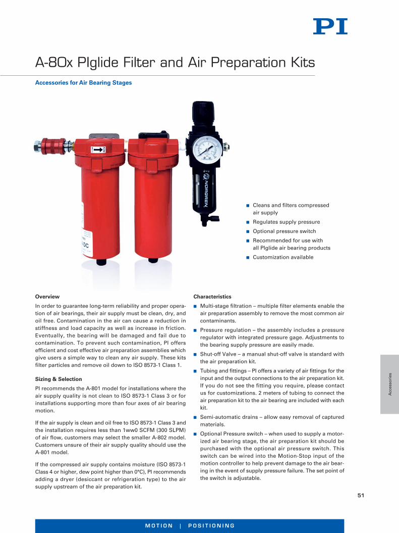
M O T I O N | P O S I T I O N I N G
51
n Cleans and filters compressed air supply
n Regulates supply pressure
n Optional pressure switch
n Recommended for use with all PIglide air bearing products
n Customization available
Overview
In order to guarantee long-term reliability and proper opera-tion of air bearings, their air supply must be clean, dry, and oil free. Contamination in the air can cause a reduction in stiffness and load capacity as well as increase in friction. Eventually, the bearing will be damaged and fail due to contamination. To prevent such contamination, PI offers efficient and cost effective air preparation assemblies which give users a simple way to clean any air supply. These kits filter particles and remove oil down to ISO 8573-1 Class 1.
Sizing & Selection
PI recommends the A-801 model for installations where the air supply quality is not clean to ISO 8573-1 Class 3 or for installations supporting more than four axes of air bearing motion.
If the air supply is clean and oil free to ISO 8573-1 Class 3 and the installation requires less than 1ww0 SCFM (300 SLPM) of air flow, customers may select the smaller A-802 model. Customers unsure of their air supply quality should use the A-801 model.
If the compressed air supply contains moisture (ISO 8573-1 Class 4 or higher, dew point higher than 0°C), PI recommends adding a dryer (desiccant or refrigeration type) to the air supply upstream of the air preparation kit.
Characteristics
n Multi-stage filtration – multiple filter elements enable the air preparation assembly to remove the most common air contaminants.
n Pressure regulation – the assembly includes a pressure regulator with integrated pressure gage. Adjustments to the bearing supply pressure are easily made.
n Shut-off Valve – a manual shut-off valve is standard with the air preparation kit.
n Tubing and fittings – PI offers a variety of air fittings for the input and the output connections to the air preparation kit. If you do not see the fitting you require, please contact us for customizations. 2 meters of tubing to connect the air preparation kit to the air bearing are included with each kit.
n Semi-automatic drains – allow easy removal of captured materials.
n Optional Pressure switch – when used to supply a motor- ized air bearing stage, the air preparation kit should be purchased with the optional air pressure switch. This switch can be wired into the Motion-Stop input of the motion controller to help prevent damage to the air bear- ing in the event of supply pressure failure. The set point of the switch is adjustable.
Accessories for Air Bearing Stages
A-80x PIglide Filter and Air Preparation Kits
Acc
esso
ries
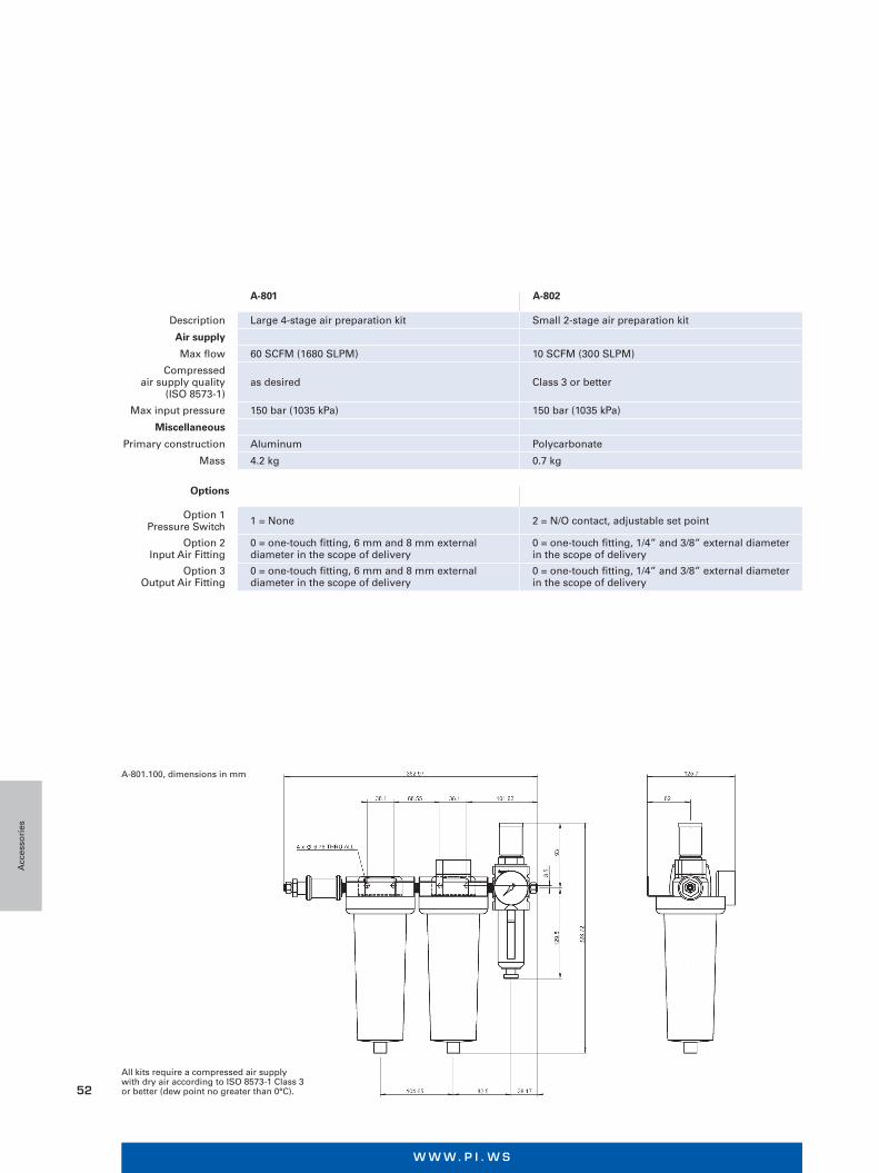
W W W. P I . W S
52
A-801 A-802
Description Large 4-stage air preparation kit Small 2-stage air preparation kit
Air supply
Max flow 60 SCFM (1680 SLPM) 10 SCFM (300 SLPM)
Compressed air supply quality
(ISO 8573-1)as desired Class 3 or better
Max input pressure 150 bar (1035 kPa) 150 bar (1035 kPa)
Miscellaneous
Primary construction Aluminum Polycarbonate
Mass 4.2 kg 0.7 kg
Options
Option 1 Pressure Switch 1 = None 2 = N/O contact, adjustable set point
Option 2 Input Air Fitting
0 = one-touch fitting, 6 mm and 8 mm external diameter in the scope of delivery
0 = one-touch fitting, 1/4” and 3/8” external diameter in the scope of delivery
Option 3 Output Air Fitting
0 = one-touch fitting, 6 mm and 8 mm external diameter in the scope of delivery
0 = one-touch fitting, 1/4” and 3/8” external diameter in the scope of delivery
All kits require a compressed air supply with dry air according to ISO 8573-1 Class 3 or better (dew point no greater than 0°C).
A-801.100, dimensions in mm
Acc
esso
ries
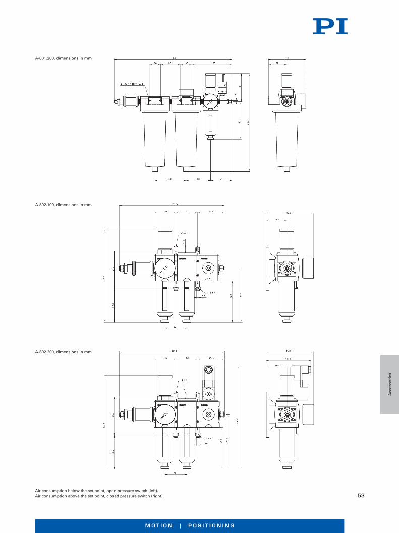
M O T I O N | P O S I T I O N I N G
53
A-801.200, dimensions in mm
Air consumption below the set point, open pressure switch (left).Air consumption above the set point, closed pressure switch (right).
A-802.100, dimensions in mm
A-802.200, dimensions in mm
Acc
esso
ries

W W W. P I . W S
54
V-273, V-275, V-277PIMag® VC Voice Coil Actuators High Dynamics & Force Control Option
n Push force up to 20 N
n Velocity up to 750 mm/s
n Integrated linear encoder, 0.01 µm resolution
n Weight force compensation
n Optional force sensor with 1 mN resolution
n High scanning frequencies, fast step-and-settle
n Wear-free flexure guiding for long lifetime
n Compact design & customization
V-522, V-524, V-528 High-Dynamics PIMag® Linear Stage Voice Coil Direct Drive With Direct Position Measurement
n Fast scanning and positioning
n Travel ranges 5 mm, 10 mm, 20 mm
n Scanning frequencies of more than 10 Hz
n Max. velocity 250 mm/s
n Crossed roller bearings for the highest precision
Linear Motors and Voice Coil Drives
Product Overview PIMag® Stages
Pro
du
ct O
verv
iew
P
IMag
® S
tag
es
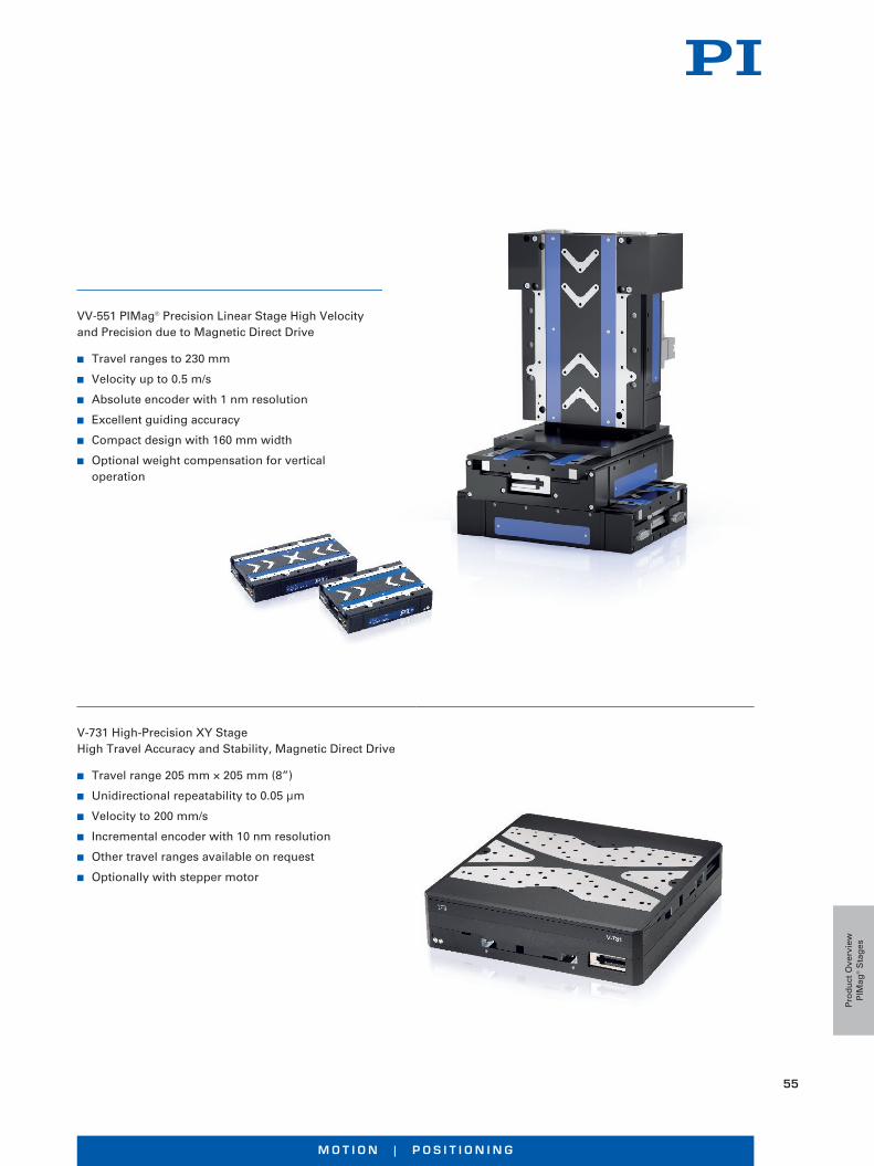
M O T I O N | P O S I T I O N I N G
55
VV-551 PIMag® Precision Linear Stage High Velocity and Precision due to Magnetic Direct Drive
n Travel ranges to 230 mm
n Velocity up to 0.5 m/s
n Absolute encoder with 1 nm resolution
n Excellent guiding accuracy
n Compact design with 160 mm width
n Optional weight compensation for vertical operation
V-731 High-Precision XY Stage High Travel Accuracy and Stability, Magnetic Direct Drive
n Travel range 205 mm × 205 mm (8”)
n Unidirectional repeatability to 0.05 µm
n Velocity to 200 mm/s
n Incremental encoder with 10 nm resolution
n Other travel ranges available on request
n Optionally with stepper motor
Pro
du
ct O
verv
iew
P
IMag
® S
tag
es
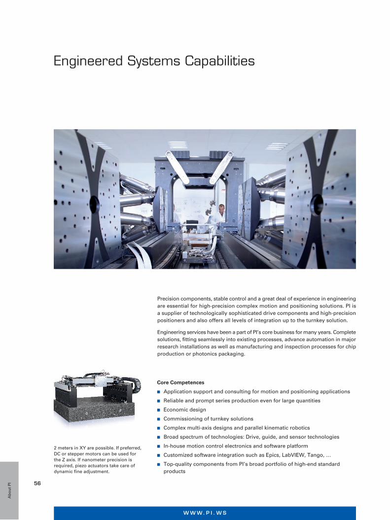
W W W. P I . W S
56
Gantries are normally equipped with linear motors. Travel ranges of up to 2 meters in XY are possible. If preferred, DC or stepper motors can be used for the Z axis. If nanometer precision is required, piezo actuators take care of dynamic fine adjustment.
Engineered Systems Capabilities
Precision components, stable control and a great deal of experience in engineering are essential for high-precision complex motion and positioning solutions. PI is a supplier of technologically sophisticated drive components and high-precision positioners and also offers all levels of integration up to the turnkey solution.
Engineering services have been a part of PI’s core business for many years. Complete solutions, fitting seamlessly into existing processes, advance automation in major research installations as well as manufacturing and inspection processes for chip production or photonics packaging.
Core Competences
n Application support and consulting for motion and positioning applications
n Reliable and prompt series production even for large quantities
n Economic design
n Commissioning of turnkey solutions
n Complex multi-axis designs and parallel kinematic robotics
n Broad spectrum of technologies: Drive, guide, and sensor technologies
n In-house motion control electronics and software platform
n Customized software integration such as Epics, LabVIEW, Tango, …
n Top-quality components from PI’s broad portfolio of high-end standard products
Ab
ou
t P
I

M O T I O N | P O S I T I O N I N G
57
WHAT IS “WORLD CLASS”Customers everywhere would define “World Class Customer Support” differently. They may consider the highest priority being the speed of response, the level of competence of the person that deals with the request, or it could simply be how quickly the solution was found. Whatever the priority is for customer service and support, PI is committed to exceeding all expectations that relate to our service deliverables.
PI’s Global Service Division (GSD) is focused on ensuring that:
n The Right People are;
n In the Right Place;
n At the Right Time;
n With the Right Skills.
This level of conditioning means that PI’s customers are able to benefit from World Class customer support services regardless of their requirement, challenge or need.
PI’s Global Services
SUPPORT FROM START TO FINISHPI is dedicated to supporting its customers’ right from the initial consultation through to when a customer has purchased a PI system. But we don’t stop there, PI’s services division is committed to ensuring that every aspect of owning a PI stage is catered for. Including:
n Quick Start – On-site support setting up a new system;
n Training – Ensuring that a new user gets the most out of their PI system;
n Support – On-going remote and on-site continued support for the whole life of any system.
Every customer is unique with their applications, environ- ments, challenges and the way they like to be supported. As such, PI has a series of packaged service offerings to cover most customer demands, but in addition to that, PI can design bespoke flexible service packages that are tailored exactly to match each customer needs.
Ab
ou
t P
I
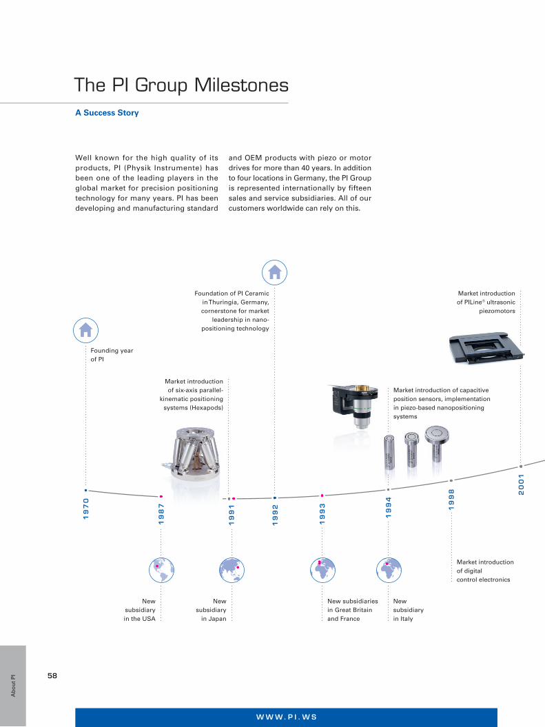
W W W. P I . W S
58
Market introduction of capacitive position sensors, implementation in piezo-based nanopositioning systems
New subsidiaryin Italy
New subsidiary
in Japan
Foundation of PI Ceramicin Thuringia, Germany, cornerstone for market
leadership in nano-positioning technology
New subsidiary in the USA
Market introductionof six-axis parallel-
kinematic positioning systems (Hexapods)
Market introductionof digitalcontrol electronics
Market introductionof PILine® ultrasonic
piezomotors
Market introductionof the NEXLINE®
high-performancepiezo linear drives
Market introductionof the magnetic
PIMag® direct drives
Acquisitionof majority shares
in miCos GmbH,Eschbach, Germany
Founding year of PI
New subsidiariesin Great Britainand France
New subsidiaryin China
Market introductionof the PICMA®
multilayer piezo actuators
New subsidiariesin Korea and
Singapore
Market introductionof Q-Motion®
and PiezoMikes
Market introductionof NEXACT®
piezo linear drives
Introduction of air bearings
Acquisition of Nelson
Air Corp., USA
19
92 19
98 20
01
20
04
20
07
19
87
19
70
19
91
19
93
20
02
20
11
20
14
20
15
19
94
Acquisition of majority shares in ACS Motion Control
20
16
New subsidiariesin Taiwan and the
Netherlands
Well known for the high quality of its products, PI (Physik Instrumente) has been one of the leading players in the global market for precision positioning technology for many years. PI has been developing and manufacturing standard
The PI Group MilestonesA Success Story
and OEM products with piezo or motor drives for more than 40 years. In addition to four locations in Germany, the PI Group is represented internationally by fifteen sales and service subsidiaries. All of our customers worldwide can rely on this.
Ab
ou
t P
I
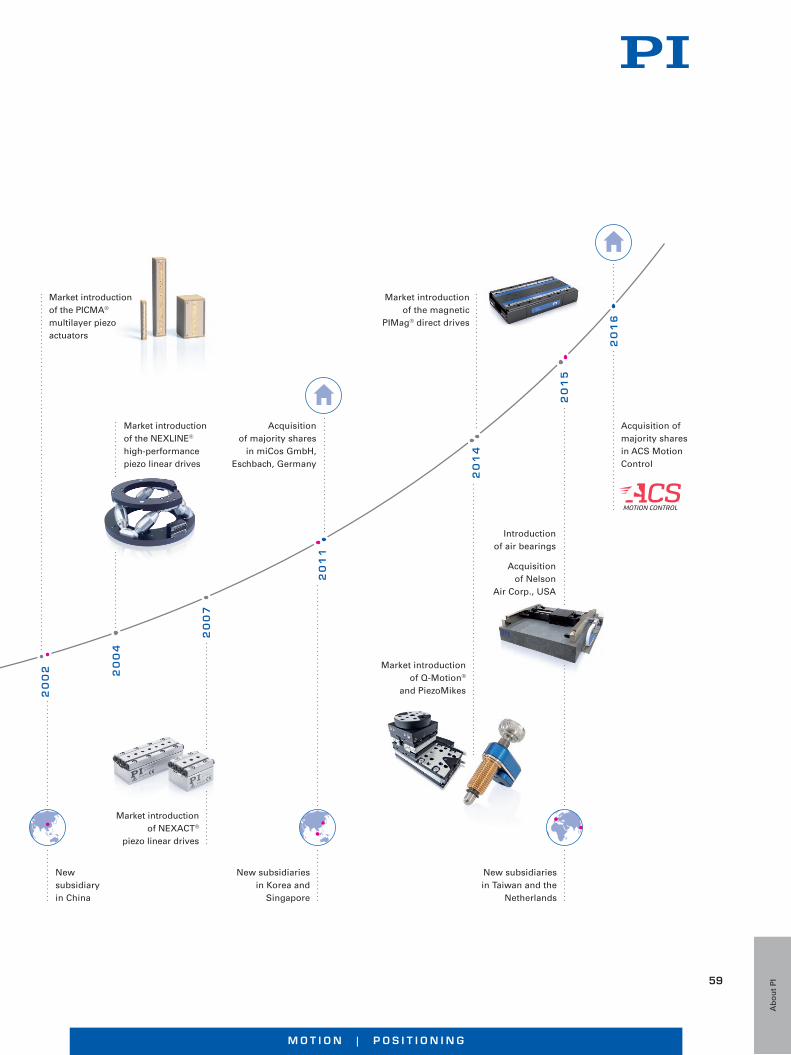
M O T I O N | P O S I T I O N I N G
59
Market introduction of capacitive position sensors, implementation in piezo-based nanopositioning systems
New subsidiaryin Italy
New subsidiary
in Japan
Foundation of PI Ceramicin Thuringia, Germany, cornerstone for market
leadership in nano-positioning technology
New subsidiary in the USA
Market introductionof six-axis parallel-
kinematic positioning systems (Hexapods)
Market introductionof digitalcontrol electronics
Market introductionof PILine® ultrasonic
piezomotors
Market introductionof the NEXLINE®
high-performancepiezo linear drives
Market introductionof the magnetic
PIMag® direct drives
Acquisitionof majority shares
in miCos GmbH,Eschbach, Germany
Founding year of PI
New subsidiariesin Great Britainand France
New subsidiaryin China
Market introductionof the PICMA®
multilayer piezo actuators
New subsidiariesin Korea and
Singapore
Market introductionof Q-Motion®
and PiezoMikes
Market introductionof NEXACT®
piezo linear drives
Introduction of air bearings
Acquisition of Nelson
Air Corp., USA
19
92 19
98 20
01
20
04
20
07
19
87
19
70
19
91
19
93
20
02
20
11
20
14
20
15
19
94
Acquisition of majority shares in ACS Motion Control
20
16
New subsidiariesin Taiwan and the
Netherlands
Ab
ou
t P
I
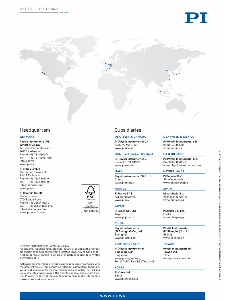
BR
O59
E P
Iglid
e S
ub
cata
log
06/
2017
1. S
ub
ject
to
ch
ang
e w
ith
ou
t n
oti
ce. ©
Ph
ysik
Inst
rum
ente
(P
I) G
mb
H &
Co
. KG
201
7
W W W. P I . W S
© Physik Instrumente (PI) GmbH & Co. KGAll contents, including texts, graphics, data etc., as well as their layout, are subject to copyright and other protective laws. Any copying, modi-fication or redistribution in whole or in parts is subject to a written permission of PI.
Although the information in this document has been compiled with the greatest care, errors cannot be ruled out completely. Therefore, we cannot guarantee for the information being complete, correct and up to date. Illustrations may differ from the original and are not bind-ing. PI reserves the right to supplement or change the information provided without prior notice.
Headquarters GERMANY
Physik Instrumente (PI) GmbH & Co. KGAuf der Roemerstrasse 1 76228 Karlsruhe Phone +49 721 4846-0 Fax +49 721 4846-1019 [email protected] www.pi.ws
PI miCos GmbHFreiburger Strasse 30 79427 Eschbach Phone +49 7634 5057-0 Fax +49 7634 5057-99 [email protected] www.pi.ws
PI Ceramic GmbHLindenstrasse 07589 Lederhose Phone +49 36604 882-0 Fax +49 36604 882-4109 [email protected] www.piceramic.com
Subsidiaries USA (East) & CANADA USA (West) & MEXICO
PI (Physik Instrumente) L.P.Auburn, MA 01501 www.pi-usa.us
PI (Physik Instrumente) L.P.Irvine, CA 92620 www.pi-usa.us
USA (San Francisco Bay Area) UK & IRELAND
PI (Physik Instrumente) L.P.Sausalito, CA 94965 www.pi-usa.us
PI (Physik Instrumente) Ltd.Cranfield, Bedford www.physikinstrumente.co.uk
ITALY NETHERLANDS
Physik Instrumente (PI) S. r. l.Bresso www.pionline.it
PI Benelux B.V.Sint-Oedenrode www.pi.ws/benelux
FRANCE SPAIN
PI France SASAix-en-Provence www.pi.ws
Micos Iberia S.L.Vilanova i la Geltrú www.pimicos.es
JAPAN
PI Japan Co., Ltd.Tokyo www.pi-japan.jp
PI Japan Co., Ltd.Osaka www.pi-japan.jp
CHINA
Physik Instrumente (PI Shanghai) Co., Ltd.Shanghai www.pi-china.cn
Physik Instrumente (PI Shanghai) Co., Ltd.Beijing www.pi-china.cn
SOUTHEAST ASIA TAIWAN
PI (Physik Instrumente) Singapore LLPSingapore www.pi-singapore.sg For ID / MY / PH / SG / TH / VNM
Physik Instrumente (PI) Taiwan Ltd.Taipei www.pi-taiwan.com.tw
KOREA
PI Korea Ltd.Seoul www.pikorea.co.kr
M O T I O N | P O S I T I O N I N G


