155
Pilot Guide & Operating Manual Skymap IIIC™ & Tracker IIIC™ ©Skyforce Avionics Ltd 2006

Pilot Guide & Operating Manual
Skymap IIIC™ & Tracker IIIC™
©Skyforce Avionics Ltd 2006

Skymap IIIC™ & Tracker IIIC™
Pilot Guide & Operating Manual
Manual Revision: SM2105-09 SIIIC Pilot Guide.doc Unit Software Version 1.22 + (System Model Packages SM4000 & TR4000) Aeronautical Database: - Supplied courtesy of Jeppesen® Cartographic Database - AND Products B.V. Topographic – NOAA (National Oceanographic Atmospheric Administration) CONTACT ADDRESS
Skyforce Avionics Limited 5 the Old Granary Boxgrove, Chichester West Sussex PO18 0ES Tel: +44 (0) 1243 783763 Fax: +44 (0) 1243 783992 Email: [email protected]
Honeywell International Inc.One Technology Center23500 West 105th Street
Olathe, KansasUSA 66061-1950 USATel: 001 913 712 2613Fax: 001 913 712 1302
Email: [email protected]

ELECTRONIC DOCUMENT DETAILS NETWORK PATH AND FILE NAME FILE
TYPE/VERSION PRINTER
\\Kent\released_dwgs\SM4000\Master Manuals Microsoft® Word Network
HARD DOCUMENT DETAILS REVISION DOI No. ORIGINATOR DESCRIPTION of CHANGE DATE
9 DOI 159 D Allen Add description of software versions and release document into DOI system
19/07/06
DOCUMENT APPROVAL Authorised for Release for and on Behalf of Skyforce Avionics Limited:
Steve White – Hardware Design Specialist
NOTICES PROPRIETARY NOTICE The information disclosed within this document or separately supplied in furtherance of this document includes proprietary rights of Skyforce Avionics Ltd. and Honeywell International Inc. Neither this document nor the information disclosed herein or of a supplementary nature shall be reproduced or transferred to other documents or used or disclosed to others for manufacturing purposes, or for any other purposes, except as specifically authorised in writing by Skyforce Avionics Ltd. or Honeywell International Inc. Skyforce Avionics Ltd. is a subsidiary of Honeywell International Inc. Copyright © 2006 Honeywell International Inc. All rights reserved. TRADEMARK NOTICE “Skyforce” and the Skyforce logo are registered trademarks of Honeywell International Inc., U.S. and UK Patent & Trademark Office’s. FLIGHT MANUAL The information contained with this manual is for reference use only. If any information herein conflicts with similar information contained within the Aeroplane Flight Manual Supplement, the information in the Aeroplane Flight Manual Supplement shall take precedence. Information in this document is subject to change without notice. Honeywell reserves the right to change or improve its products and to make changes in the content without notification.

TABLE OF CONTENTS
SECTION 1 BASIC OPERATION 1 INTRODUCTION 1 DEFINITIONS, ACRONYMS AND ABBREVIATIONS 3
Definitions 3 Acronyms and Abbreviations. 4
A QUICK LOOK AT YOUR UNIT 8 KEY TO DRAWINGS 8 KEY TO DRAWING 9 Standard Accessories 9 Optional Accessories 9
GENERAL INFORMATION 11 Soft Keying 11 Screen Orientation 11 Software Architecture 11 Memory Locations 14 Screen Icons 14
POWER AND ANTENNA CONSIDERATIONS 16 Power 16 Antenna Considerations (Skymap IIIC only) 18
SECTION 2 QUICK REFERENCE GUIDE 1 INTRODUCTION 1 INITIALISING YOUR UNIT 1 SOFTWARE STRUCTURE 2
Selecting Demo Mode 2 DATABASE SELECTION 3
A Quick Word On DIRECT TOs And Flight Plans 3 VISUAL DIRECT TO AND DATA INTERROGATION 4
DIRECT TO a Specific Latitude- And Longitude 4 Manual DIRECT TO And Data Interrogation 5
USER WAYPOINTS 5 Editing/Creating A User Waypoint Manually 5 Editing/Creating A User Waypoint Visually 5 Saving A User Waypoint In Flight 6
FLIGHT PLANS 7 Editing/Creating A Flight Plan Manually 7 Editing/Creating A Flight Plan Visually 7 Selecting A Flight Plan To Fly 8 Selecting A Map Mode Navigation Presentation 9 Viewing ETAs/Skip Waypoints 9 Ten Nearest Search 9
Rev 9 Jul 2006 i Skymap/Tracker IIIC Pilot's Guide

SETUP MAP FUNCTIONS 10 SETUP OF NAVIGATION FUNCTIONS 12 CLEAR MEMORY 13 SECTION 3 DETAILED OPERATION 1 TITLE AND HELP SCREENS 1
Self Test and Initialisation 2 Main Menu Screen 3 Note Pad Screen 3
GPS STATUS SCREENS (SKYMAP IIIC ONLY) 5 Adjusting Time and Date 7 Setting Local Time Offset 8 Setting Present Position 9
DATA INPUT 11 FLIGHT PLANNING SCREENS 13
User Waypoints 13 Viewing User Waypoints 15 Manual User Waypoint Editing 16 Graphical User Waypoint Editing 17 Editing User Airports 18 Flight Plans 18 Manual Flight Plan Building and Editing 19 Manually Inserting a Waypoint into a Flight Plan and Manual DIRECT TO 20 Graphical Viewing and Editing of Flight Plans 23 Airways Flight Planning 25
MAP MODE SCREENS 26 Data Interrogation and Graphical DIRECT TO 27
Airport Information 28 Beacon Information 29 General Icon Information 30 Airspace Interrogation 30
NAV MENU SCREENS 32 Selecting a Flight Plan 34 Ten Nearest 36
Airports 36 Beacons 37
MAP MODE WITH NAV INFORMATION 39 Viewing En-route ETA’s and Direct-To Page 40
Direct To 41 Arrival at an En-route User Waypoint 42 Arrival at Your Final Destination 43 Alternative Navigation Map Modes 44
TOPO ON / TOPO OFF Large Text Mode 44 TOPO ON / TOPO OFF CDI (Pseudo CDI) Mode: 44
DEMO MODE 47 E6-B CALCULATOR 49
Rev 9 Jul 2006 ii Skymap/Tracker IIIC Pilot's Guide

Density Altitude/TAS/Winds Aloft Calculator 49 Vertical Navigation (VNAV) 50 Trip/Fuel Planning 52 Sunset/Sunrise Calculator. 53
APPENDIX A SETUP SCREENS 1 SETUP SCREENS 1
Map Setup Screens 1 NAV Mode Setup 7 Personal Identification Number (PIN) Setup 9
Auto Power-On Lock 11 Installation and Diagnostic Screens 13
Screen Position Setup 13 View Logs 14 Clear Memory 15 Data In/Out 17
APPENDIX B WARNING SCREENS 1 RAM Lost Warning 1 Memory Battery Warning 1 PIN Lock Warning 2 Lock Out Warning 2 New Data Card Warning 3
APPENDIX C MEMORY CARDS 1 MEMORY CARDS 1
Data Areas 1 Changing the memory card 1 Minimum Safe Altitudes (MSA) 2
Flight Plan building. 2 During Flight 2
Worldwide ICAO Codes. 3 APPENDIX D HOW DOES GPS WORK? 1 INTRODUCTION TO GPS 1
What Is GPS? 1 How Does It Work? 1 Accuracy and Reliability 2
APPENDIX E DIFFERENTIAL FUNCTIONS (SKYMAP IIIC ONLY) 1 DIFFERENTIAL GPS 1
What Is DGPS? 1 How Does DGPS Work? 1 Uses Of DGPS 2 Data Connection 2
APPENDIX F SERIAL DATA OUTPUT SENTENCES 1 SERIAL DATA FORMATS 1
NMEA 0183 Data Format 1 NMEA – RMC Sentence 1 NMEA – GGA Sentence. 1
Rev 9 Jul 2006 iii Skymap/Tracker IIIC Pilot's Guide

NMEA – RMB Sentence 1 Notes on the RMB sentence 2 RS-232C AR-NAV Data Format 3 Notes on the AR-NAV sentence. 3
APPENDIX G SERVICE AND WARRANTY 1 APPENDIX H PREVIOUS SOFTWARE RELEASES 1
Rev 9 Jul 2006 iv Skymap/Tracker IIIC Pilot's Guide

THIS PAGE INTENTIONALLY BLANK
Rev 9 Jul 2006 v Skymap/Tracker IIIC Pilot's Guide

BASIC OPERATION
SECTION 1 BASIC OPERATION
B
ASI
C O
PER
ATI
ON
INTRODUCTION All of us at Honeywell congratulate you on choosing this product. You are now the owner of one of the most sophisticated yet simple-to-use navigational aids available today. We understand you probably can't wait to see it in action but before you try to use it do please take the time to read through this Manual and understand its many interesting and useful features. Time spent in familiarising yourself with your new Bendix/King unit will be more than repaid by trouble-free operation later, and more importantly safe and accurate navigation. We have made the operation of this unit as intuitive as possible through the use of soft keying and on-screen help, thus reducing users' dependence on the Manual. You should very quickly find that handling it efficiently and expertly becomes second nature to you. Don't be afraid to experiment. No matter which Key you activate, your unit will not be damaged. If you do get into a mess, simply switch off and back on again to reset all functions. We must mention just one word of caution. Never remove the memory card whilst the unit is switched on and never attempt to switch the unit on when there is no memory card fitted. Whichever model of our equipment you have chosen, we at Honeywell are sure you will be pleased with its performance. We thank you for your custom and wish you many happy and safe hours flying.
WARNING
The Global Positioning System (GPS) satellite constellation is operated by the Department of Defence (DoD) of the United States, which is solely responsible for its accuracy and maintenance. Although declared fully operational on July 17th 1995, the system is still under development and subject to changes, which could affect the accuracy and performance of all GPS equipment. Use this equipment at your own risk. Your new Bendix/King equipment is a precision navigation aid but like any navigational aid it can be misused or misinterpreted and so become unsafe. You are strongly advised to read and fully understand this Manual before using it. Your unit has a DEMO MODE or simulation facility that allows you to practice with it before you begin using it for actual navigation. Whenever you are using the unit for navigation in the air you should treat it as a supplemental navigation system. You should always carefully compare indications from your Bendix/King equipment with the information available from all other navigation sources including NDB’s, VOR’s, DME's, visual sightings, charts, etc. For safety, any discrepancies observed should be resolved immediately. The altitude calculated by GPS equipment is geometric height above a theoretical mean sea level of a mathematically calculated ellipsoid that approximates to the shape of the earth. This altitude can differ significantly from that displayed by your pressure altimeter. You must therefore NEVER USE GPS ALTITUDE FOR VERTICAL NAVIGATION OR TERRAIN CLEARANCE. The coloured terrain elevation feature is provided solely as an aid to visual identification of terrain features and must never be used for terrain clearance. The European Obstacle Data has been generated from each of the countries AIP en-route
Rev 9 Jul 2006 1-1 Skymap/Tracker IIIC Pilot's Guide

BASIC OPERATION
navigation obstacles section. The respective national authorities do not guarantee that the AIP details are correct or that the list of obstacles is complete.
B
ASIC
OPER
ATIO
N
This equipment is not a replacement for your chart. It is intended as an aid to VFR navigation only. The database within the equipment has been compiled from the latest official information available, and although every care has been taken in the compilation, the manufacturers will not be held responsible for any inaccuracy or omissions therein.
WARNING
Your Bendix/King product is of superior design and craftsmanship and should be treated with care. The suggestions below will help you enjoy the product for many years.
• Keep the Skymap and all its parts and accessories out of the reach of small children.
• Keep the Skymap dry. Precipitation, humidity and liquids containing minerals will corrode the electronic circuits.
• Do not use or store the Skymap in dusty, dirty areas as its components may be damaged.
• Do not store the Skymap in excessively hot areas. High temperatures can shorten the life of electronic devices, damage batteries and warp or melt plastics.
• Do not store the Skymap in excessively cold areas and try to avoid transferring the unit suddenly from a cold to a warm environment. When the unit warms up to its normal temperature, condensation can form inside, which may damage the electronic circuits. If you suspect that there may be internal condensation, allow the unit to warm up slowly and the condensation to clear of its own accord before applying power.
• Do not attempt to open the casing. Only trained and qualified Honeywell technicians can service and repair your unit. Other than the data card the Skymap contains no user-serviceable parts. Non-expert handling may damage the Skymap.
• Do not drop or knock the Skymap. Rough handling may damage the case or internal components.
• Do not use harsh chemicals, cleaning solvents or strong detergents to clean the Skymap. Wipe it with a clean, dry cloth.
• Do not dispose of the Skymap by fire.
Rev 9 Jul 2006 1-2 Skymap/Tracker IIIC Pilot's Guide
BASIC OPERATION
DEFINITIONS, ACRONYMS AND ABBREVIATIONS
B
ASI
C O
PER
ATI
ON
Definitions alphabetic: any of the following characters (b/ is a space): b/ABCDEFGHIJKLMNOPQRSTUVWXYZ alphanumeric: any of the following characters (b/ is a space): b/ABCDEFGHIJKLMNOPQRSTUVWXYZ0123456789 baud: bits per sec barometric altitude: pressure altitude corrected for barometric altimeter setting bearing to waypoint: bearing from the present position to the active waypoint measured clockwise relative to true or magnetic north (true is implied unless magnetic is specified) cross track error: distance from the present position to the nearest point on the desired course, and the direction (right or left) from the desired course to the present position cursor field: a character position or group of adjacent character positions on which a cursor can appear data entry field: A data entry field is a data field where the ENTER, SET or SELECT button must be pressed before data entered in the field becomes effective. A data entry field can be a single or multiple character cursor field. During data entry, the active cursor field remains reverse video. data field: a character position or group of adjacent character positions which display a single data item; a data field may be a single character cursor field, or may contain multiple characters. data list: an ordered list of data elements which a given cursor field can accept desired track: The angle, which the desired flight path makes with respect to true north at the point nearest the present position. Magnetic desired track uses the local magnetic variation. destination: If the active waypoint is not in the active flight plan, the active waypoint is the destination. If the active waypoint is in the active flight plan, the final waypoint in the flight plan is the destination. distance to waypoint: distance from the present position to the active waypoint en route safe altitude: the highest minimum safe altitude which will be encountered for a given flight path (present position to destination, via flight plan if appropriate; or a flight path being analysed by trip planning) ground speed: absolute value of the rate of change of position headwind: difference between true airspeed and ground speed when true airspeed is
Rev 9 Jul 2006 1-3 Skymap/Tracker IIIC Pilot's Guide

BASIC OPERATION
more than ground speed
B
ASIC
OPER
ATIO
N
knots: Nautical miles per hour minimum safe altitude: Minimum safe altitude is the highest minimum off route altitude for any sector within a 10 N.M. square centred at a given position. A minimum off route altitude of 7000 feet or less clears all known obstructions and terrain in a sector by 1000 feet; a minimum off route altitude greater than 7000 feet clears all terrain by 2000 feet. A sector is an area bounded by a 1º latitude/longitude grid. RAIM: Receiver Autonomous Integrity Monitoring - A technique whereby a GPS receiver determines the integrity of the GPS navigation signals by a consistency check among redundant pseudo range measurements. scrolling region: a set of consecutive cursor fields which display a portion of a scroll list; "scroll up" means that the data item in each cursor field in the scrolling region moves to the preceding cursor field. The data item in the first cursor field disappears from the page, and the last cursor field displays the next item in the scroll list; "scroll down" is the opposite. If there is other data associated with the data in the cursor fields (such as waypoint numbers in flight plans), it also moves. selected course: The angle, which the desired flight path makes with respect to true north at the active waypoint. Magnetic selected course uses the magnetic variation at the active waypoint; if the active waypoint is a VOR, the magnetic variation stored for that VOR is used. special use airspace: any of the following: prohibited area, restricted area, warning area, alert area, MOA, Class CARSA, Class BTCA, unknown, danger, caution, training, CTA, or TMA type standard rate turn: 3º/sec tailwind: difference between ground speed and true airspeed when ground speed is more than true airspeed terminal waypoints: waypoints that are duplicated within a country code or "unnamed" waypoints associated with an approach that are assigned to distinct airports time to waypoint: distance to waypoint divided by ground speed track: angle of the aircraft's path over the ground measured clockwise relative to true or magnetic north (true is implied unless magnetic is specified) Acronyms and Abbreviations. AC: alternating current ACT: active (waypoint or flight plan) ADF: automatic direction finder ANSI: American National Standards Institute APT: airport
Rev 9 Jul 2006 1-4 Skymap/Tracker IIIC Pilot's Guide
BASIC OPERATION
ARTCC: air route traffic control centre
B
ASI
C O
PER
ATI
ON
ASCII: American standard code for information interchange ATC: air traffic control ATF: aerodrome traffic frequency ATIS: automatic terminal information service A/C: aircraft baud: or Baud Rate; a measurement of data transmission speed BRG: bearing CAA: Civil Aviation Authority CAS: calibrated airspeed COM: communication CDI: course deviation indicator CTA: control area CTAF: common traffic advisory frequency CTR: centre CWI: continuous wave interference dB: decibels DC: direct current DIS: distance DME: distance measuring equipment DOD: United States Department of Defence DOT: United States Department of Transportation EFIS: electronic flight instrument system ELT: emergency locator transmitter ESA: en route safe altitude ETE: estimated time en route FAA: Federal Aviation Administration FAF: final approach fix FAR: Federal Aviation Regulations FPL: flight plan FPM: feet per minute FSS: flight service station ft: feet FT: feet G: gravitational acceleration = 32.2 ft/sec2 = 9.8 m/sec2 GAL: gallons GPS: Global Positioning System hr: hour HSI: horizontal situation indicator Hz: hertz IAF: initial approach fix IAP: instrument approach procedure IEEE: Institute of Electrical and Electronics Engineers IFR: instrument flight rules in.: inches INT: intersection kHz: kilohertz Kt.: knots KΩ: kilohms LAT: latitude
Rev 9 Jul 2006 1-5 Skymap/Tracker IIIC Pilot's Guide

BASIC OPERATION
LB: pounds
B
ASIC
OPER
ATIO
N
LED: light emitting diode LON: longitude LONG: longitude LRU: line replaceable unit m: meters mA: milliamperes MATZ: Military air traffic zone MAHP: missed approach holding point MAP: missed approach point mB: millibars MF: mandatory frequency MHz: megahertz mi: statute miles min: minutes MOA: military operation area MSA: minimum safe altitude msec: milliseconds NDB: non-directional beacon N.M.: nautical miles NPA: non-precision approach NVM: non-volatile memory OBI: Omni-directional bearing indicator OBS: Omni-directional bearing selector PETE: pointer ETE RAD: radial RAM: random access memory REF: reference RMI: radio magnetic indicator RTCA: Radio Technical Commission for Aeronautics SA: Selective Availability (intentional errors introduced by the DoD) SAT: static air temperature sec: seconds SID: Standard Instrument Departure SNR: signal to noise ratio STAR: Standard Terminal Arrival Route SUP: supplemental waypoint TAS: true airspeed TAT: total air temperature TD: time difference TMA: terminal control area TSO: technical standard order UTC: universal co-ordinated time (same as Greenwich Mean Time) V: volts VHF: very high frequency VNAV: vertical navigation VOR: very high frequency Omni-directional radio range W: Watts wpt: waypoint
sec: microsecond
Rev 9 Jul 2006 1-6 Skymap/Tracker IIIC Pilot's Guide
BASIC OPERATION
V: microvolts
B
ASI
C O
PER
ATI
ON
Ω: ohms ºC: degrees Celsius ºF: degrees Fahrenheit
Rev 9 Jul 2006 1-7 Skymap/Tracker IIIC Pilot's Guide
BASIC OPERATION
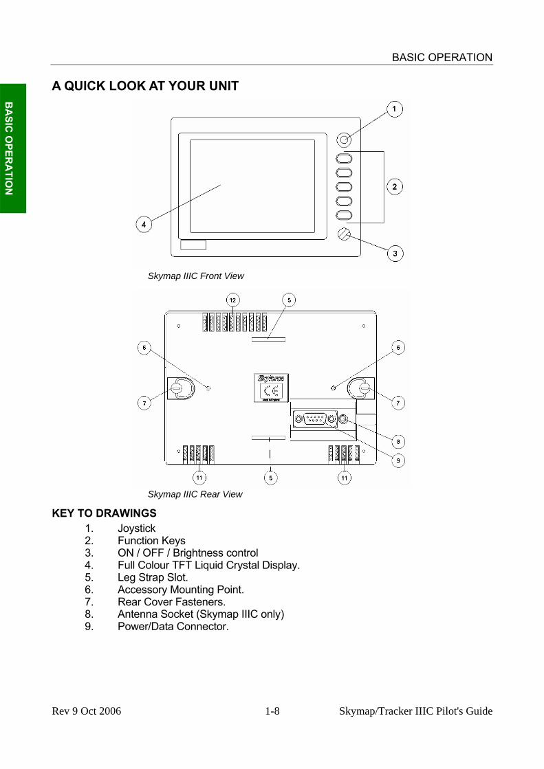
A QUICK LOOK AT YOUR UNIT
B
ASIC
OPER
ATIO
N
Skymap IIIC Front View
Skymap IIIC Rear View
KEY TO DRAWINGS 1. Joystick 2. Function Keys 3. ON / OFF / Brightness control 4. Full Colour TFT Liquid Crystal Display. 5. Leg Strap Slot. 6. Accessory Mounting Point. 7. Rear Cover Fasteners. 8. Antenna Socket (Skymap IIIC only) 9. Power/Data Connector.
Rev 9 Oct 2006 1-8 Skymap/Tracker IIIC Pilot's Guide

BASIC OPERATION
B
ASI
C O
PER
ATI
ON
Skymap IIIC Rear View - Back Case Removed
KEY TO DRAWING 8. Antenna Socket (Skymap IIIC only) 9. Power/Data Connector. 10. Memory Card. 11. Cooling Air Intake (do not block). 12. Cooling Air Exhaust (do not block). 13. Rear Case Earth Tab (do not bend). 14. Serial number and modification level tag. Standard Accessories SM2100 Portable Antenna with Cable and Suction Cup (Skymap IIIC only) SM2104 Carrying Case SM2200 Leg Strap SM2207 Cigar Adapter Cable (Skymap IIIC only)
SM2102 Power/Data Cable (Tracker IIIC only) SM2105 Pilots Guide SM2106 Getting Started Card Optional Accessories SM2201 Yoke Mount SM2204 Panel Mount SM2213 Panel Mount with Power/SMB Connector SM2202 Rack Mount
SM2209 Gimbal Mount SM2228 Pedestal Mount
SM2203 Avionics Interface Module (AIM) KA92 Low Profile External Antenna SM2212 SMB to BNC Adapter
SM2101 Antenna Extension Lead SM2225/6/7 AC Power Adapter
SMP514 PC Interface Cable FM25/26/2700 Flight Manager PC Software
Rev 9 Jul 2006 1-9 Skymap/Tracker IIIC Pilot's Guide

BASIC OPERATION
B
ASIC
OPER
ATIO
N
THIS PAGE INTENTIONALLY BLANK
Rev 9 Jul 2006 1-10 Skymap/Tracker IIIC Pilot's Guide

BASIC OPERATION
GENERAL INFORMATION
B
ASI
C O
PER
ATI
ON
This section of the Manual explains how your Bendix/King unit should be used and provides you with an overview of the software architecture and screen presentation. This manual provides a detailed explanation of each of the individual screens that your Bendix/King unit displays, and will take you step by step through each of them. To simplify this process each screen is numbered and indexed at the front of this Manual for reference. For those users who wish to get stuck into operating the system immediately, the Quick Reference Section of the Manual has been designed to get you up and running. The operating system of the Bendix/King Skymap IIIC and Tracker IIIC has been developed from the highly successful Skymap II software. This operating system greatly reduces the number of key presses necessary to activate the various functions, especially those most frequently used in the air. The provision of a joystick makes it considerably simpler to operate the unit and allows you fast and efficient access to most functions.
Soft Keying You will notice that a label is drawn alongside each valid key. Whenever a new function is selected, by pressing a valid key, a new screen is displayed along with its new key labels. This capability of drawing key labels that are only applicable to a particular screen is referred to as ‘soft keying’, and allows one key to perform multiple functions without the complications of multiple key presses on a conventional keypad. For the purpose of describing the function of a particular key in this Manual, assume that all the keys on the pictured screen drawings are numbered 1 - 5 from top to bottom. The ensuing text will use this numbering sequence to refer to each specific key. The number shown alongside the pictured screen drawings refers to the number of the screen, which is called when that key is pressed. By using these numbers it is possible to follow the paths through the operating system for all functions. If the word RET is printed next to a key, this means that after the key function is performed the same screen is RETurned. A good example of this is ZOOM IN. All screen drawings show the full Skymap IIIC version of software in Landscape Standard mode. Variations affecting Tracker IIIC are described in the accompanying text.
Screen Orientation The Skymap IIIC and Tracker IIIC software can be run in one of four display modes and so allows you to mount the unit either horizontally (either Landscape Standard or Inverse) or vertically (either Portrait Standard or Inverse). This enables the user to configure the unit for either left or right handed operation or place the keys along the left, right, top or bottom edges of the case. The default setting on first switch on is Landscape Standard, and it is this mode that is used to illustrate the functions of your unit in this Manual. Refer to Map Setup Screens in the Setup Screens section of this manual if you wish to alter your screen orientation.
Software Architecture The software in your Bendix/King unit is tree structured, an analogy can therefore be drawn between the trunk of a tree and MAIN MENU. MAIN MENU is the heart of the operating structure and can be accessed by pressing the HELP key after power up or the MAIN MENU key at any other time.
Rev 9 Jul 2006 1-11 Skymap/Tracker IIIC Pilot's Guide

BASIC OPERATION
B
ASIC
OPER
ATIO
N
MAIN MENU has 5 main software branches, which in turn have their own sub software branches. The diagram above depicts the complete tree structure and will serve as a good point of reference whilst you are familiarising yourself with your unit. GPS STATUS
Shows satellite signal strength, allows UTC, local offset, date and position to be set, which will speed up the initialisation of your unit.
FLIGHT PLAN
Allows user defined user waypoints and flight plans to be edited/created.
EDIT FPLN Allows user defined flight plans to be edited /created either manually or visually.
USER WPTS
Allows user defined waypoints, airports and marker functions to be edited/created either manually or visually.
DEMO MODE
Allows you to practice operating the unit on the ground using a built-in simulator.
Figure 1 Software Architecture Diagram
Rev 9 Jul 2006 1-12 Skymap/Tracker IIIC Pilot's Guide

BASIC OPERATION
NOTE PAD Allows up to 4000 characters of text, previously downloaded from a PC using Flight Manager™ software to be viewed. This Key is only available if DEMO MODE is not running. DEMO MODE can only be selected from the first screen after switching on the unit.
E6-B CALC Allows the E6-B Calculator to be used. TAS/WIND Allows density altitude, TAS and winds aloft to
be calculated. V NAV Allows vertical navigation to be Setup. TRIP/FUEL Allows fuel and trip information to be calculated. SUNSET/
RISE Allows sunset and sunrise times to be calculated.
SETUP Allows Setup of map, navigation and input/output characteristics.
MAP SETUP
Allows all map functions to be customised, including map orientation, airport names, map units, map datum, display orientation, language, minimum runway length/surface, extended track, auto zoom, zoom level map de-clutter facility, data logging rate and position reporting.
NAV SETUP
Allows all the NAV functions to be customised, including CDI scale, CDI display, CDI alarm, arrival alarm, auto next leg/leg selection philosophy, turn anticipation, flight plan display and alarms.
PIN SETUP Allows the PIN security function to be Setup. INST &
DIAGS Allows installation and diagnostics for data
input/output and GPS receiver (Skymap IIIC only) to be performed. Flight logs can be viewed and various sections of memory can be cleared from here.
MAP This is the primary operating mode of the unit. NAV MENU Accesses all navigation functions and MSA
information. Joystick toggles NAV Mode. FLIGHT
PLAN Allows a flight plan to be selected and edited.
NEAR APTS
Allows emergency search of 10 nearest airports, providing information and DIRECT TO capability. Includes Jeppesen and user defined airports which satisfies the minimum runway length and surface requirements.
B
ASI
C O
PER
ATI
ON
Rev 9 Jul 2006 1-13 Skymap/Tracker IIIC Pilot's Guide

BASIC OPERATION
NEAR NAVAID
Allows emergency search of 10 nearest beacons (VOR's and NDB's), providing information and DIRECT TO capability.
SAVE WPT Allows your present co-ordinates to be saved in the next available user waypoint number.
DIRECT TO Allows the user to perform a “goto” or DIRECT TO any point in the internal or user defined database. It may also be used to obtain information on any point in the database.
B
ASIC
OPER
ATIO
N
There are short cuts, which allow you to get to the primary operating mode, MAP mode, more easily; but in general if you wish to get to a specific function in another branch of software, work your way back up the present branch to MAIN MENU by pressing either the SAVE & EXIT, PREV PAGE or MAIN MENU key. Then select the branch of software that contains the desired function you wish to access.
Memory Locations In the function descriptions, three types of memory, RAM, NVM and Memory Card, are mentioned. You may find it useful to know where various types of information are stored in order to make best use of the equipment. The RAM (Random Access Memory) is built into the unit and is used to store all user-defined data such as User waypoints and Flight plans. The RAM is maintained by battery power from an internal Lithium cell, which should be replaced by your Bendix/King dealer every three years to prevent loss of user-defined data. The NVM (Non Volatile Memory) is also built into the unit. It stores initialisation data, serial number, PIN number and performance log details. This memory is non-volatile which means it is retained even if the memory battery is removed. If you choose to activate the PIN number security feature (similar to that available on many car radios) the non-volatile nature of the NVM ensures your PIN cannot be tampered with or erased. The Memory Card is used to hold the operating system and the database. The memory card can be replaced periodically in order to upgrade the operating system and update the database. Screen Icons When showing any map screen - airports, beacons, towns, intersections, user waypoints and many other data classes are represented by symbols or icons, many of which are user selectable in the Map Setup Screens. Please refer to the Setup Screens Section of this Manual for further details.
Rev 9 Jul 2006 1-14 Skymap/Tracker IIIC Pilot's Guide

BASIC OPERATION
B
ASI
C O
PER
ATI
ON
Rev 9 Jul 2006 1-15 Skymap/Tracker IIIC Pilot's Guide

BASIC OPERATION
POWER AND ANTENNA CONSIDERATIONS
B
ASIC
OPER
ATIO
N
Power Your unit is designed to operate from an external source providing a voltage between 10V to 33V DC. An optional AC Power (either 110V or 220/240V) Adapter is also available as an accessory for home use. A pre-wired connector is supplied with your unit. The tail end of which either has a Cigar Adapter (Skymap IIIC) or flying leads (Tracker IIIC). The cable uses four coloured cores and a braided screen. The red and blue cores of the cable should be connected to any DC supply between 10 and 33 Volts, capable of supplying 2 Amps.
1. Connect the RED core via a 3 Amp fuse to the positive (+) side of a 10V-33V DC power source.
2. Connect the BLUE core and the braided screen to the negative (-) side of the same power source.
You may also power your unit from a 12 or 24 volt automobile type cigarette lighter socket. However certain of these lack proper circuit protection and may provide an unreliable supply so we recommend that wherever possible an approved aircraft power source be installed by a licensed radio engineer. The yellow and green cores are the data in (yellow) and data out (green) lines. If your unit is a Tracker IIIC, the yellow core (data in) should be connected to the data output line of your GPS. Refer to the Data Input Section of this Manual for more details. If your unit is a Skymap IIIC, the yellow core (data in) can also be connected to the data output line of another GPS, if required and the Skymap IIIC can be switched to Tracker mode and used as a repeater for that GPS. Your unit also has a differential serial data input and external alarm outputs available on the 9 way connector for optional use. The green core of the cable is connected to the serial data output pin and may be used to drive an AirData computer, a plotter or a data recording device (see SECTION 3 APPENDIX F for details of data output).
Rev 9 Jul 2006 1-16 Skymap/Tracker IIIC Pilot's Guide
BASIC OPERATION
B
ASI
C O
PER
ATI
ON
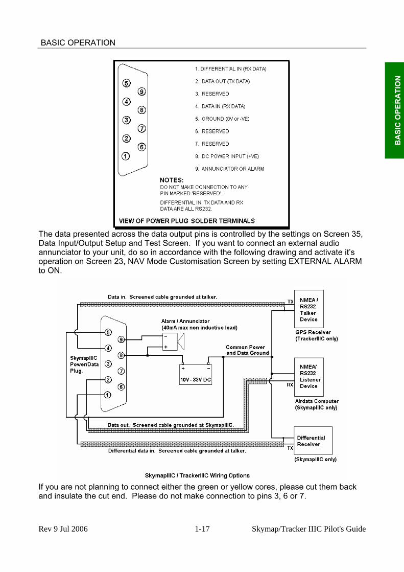
The data presented across the data output pins is controlled by the settings on Screen 35, Data Input/Output Setup and Test Screen. If you want to connect an external audio annunciator to your unit, do so in accordance with the following drawing and activate it’s operation on Screen 23, NAV Mode Customisation Screen by setting EXTERNAL ALARM to ON.
If you are not planning to connect either the green or yellow cores, please cut them back and insulate the cut end. Please do not make connection to pins 3, 6 or 7.
Rev 9 Jul 2006 1-17 Skymap/Tracker IIIC Pilot's Guide

BASIC OPERATION
Antenna Considerations (Skymap IIIC only)
B
ASIC
OPER
ATIO
N
The Skymap IIIC is supplied with a portable antenna that is convenient for use in circumstances where the unit is removed from the aircraft regularly. Your Bendix/King dealer can advise you on other antenna options to suit different applications or improve performance. When positioning the portable antenna, always ensure that the domed (the opposite side to that which carries the CE marking) face of the antenna is facing straight up to the sky and can “see” a large area of the sky, preferably right down to the horizon. In order to provide a 3-dimensional fix, Skymap IIIC needs to receive signals simultaneously from at least four satellites. The radio signals from the GPS Navstar satellites are transmitted in an extremely high frequency band (1.5GHz). They can be regarded as having approximately the same penetration capabilities as light. This means that they are able to penetrate only transparent or very thin materials and will be blocked by almost any material that blocks light. At least four and at times up to twelve GPS satellites should be in view from any place in the world at any time. These can, however, be absolutely anywhere in the sky and so, to ensure uninterrupted navigation it is essential that the antenna has direct line-of-sight contact with as much sky as possible. If the position in which you wish to locate your Skymap IIIC is shielded from the sky and the standard antenna cable is not long enough for an acceptable installation bearing the above guidelines in mind, you may choose one of several options for remote antenna sitting. The simplest is to use the Bendix/King remote antenna extension cable. This allows the portable antenna to be extended by a further 6ft (2 metres) thereby allowing mounting up to 12ft (4 meters) away from the main unit. The antenna may be held in place there by using the rubber suction cup supplied (which should be slotted into the key hole in the antenna bracket) or fixed permanently in position by using the countersunk screw mounting holes in the antenna bracket. The rubber suction cup is ideal for temporary use in vehicles and light aircraft. The portable antenna is only splash proof and not fully waterproof. Never mount this antenna permanently outside. For permanent external antenna mounting an external magnetic mount antenna is available for ground vehicles and an external low profile "tear drop" style antenna for aircraft. For more information about these accessories please contact your Bendix/King dealer.
Rev 9 Jul 2006 1-18 Skymap/Tracker IIIC Pilot's Guide

BASIC OPERATION
B
ASI
C O
PER
ATI
ON
THIS PAGE INTENTIONALLY BLANK
Rev 9 Jul 2006 1-19 Skymap/Tracker IIIC Pilot's Guide

QUICK REFERENCE GUIDE
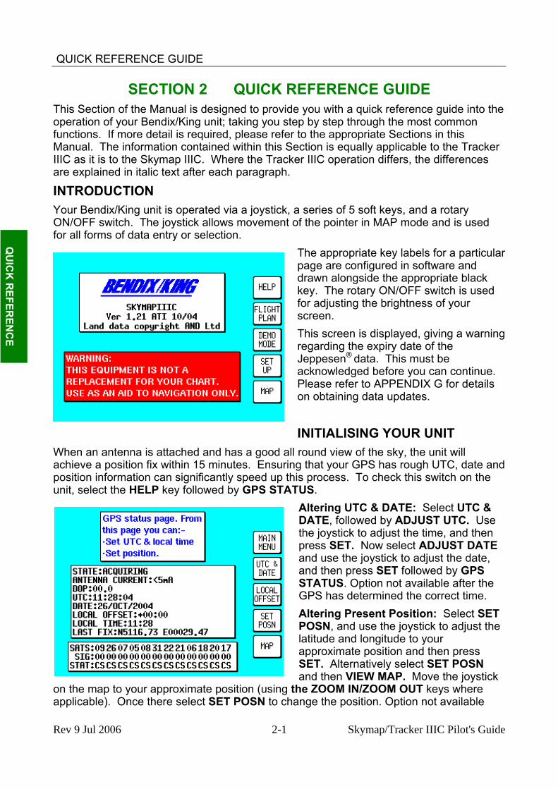
SECTION 2 QUICK REFERENCE GUIDE This Section of the Manual is designed to provide you with a quick reference guide into the operation of your Bendix/King unit; taking you step by step through the most common functions. If more detail is required, please refer to the appropriate Sections in this Manual. The information contained within this Section is equally applicable to the Tracker IIIC as it is to the Skymap IIIC. Where the Tracker IIIC operation differs, the differences are explained in italic text after each paragraph.
INTRODUCTION
Q
UIC
K R
EFEREN
CE
for all forms of data entry or selection. articular
arning
unit, select the HELP key followed by GPS STATDATE: Select UTC &
press
k
e
Your Bendix/King unit is operated via a joystick, a series of 5 soft keys, and a rotary ON/OFF switch. The joystick allows movement of the pointer in MAP mode and is used
The appropriate key labels for a ppage are configured in software and drawn alongside the appropriate blackkey. The rotary ON/OFF switch is used for adjusting the brightness of your screen. This screen is displayed, giving a wregarding the expiry date of the Jeppesen® data. This must be acknowledged before you can continue. Please refer to APPENDIX G for details on obtaining data updates.
INITIALISING YOUR UNIT When an antenna is attached and has a good all round view of the sky, the unit will achieve a position fix within 15 minutes. Ensuring that your GPS has rough UTC, date and position information can significantly speed up this process. To check this switch on the
US. Altering UTC & DATE, followed by ADJUST UTC. Use the joystick to adjust the time, and then press SET. Now select ADJUST DATE and use the joystick to adjust the date, and then press SET followed by GPS STATUS. Option not available after theGPS has determined the correct time. Altering Present Position: Select SETPOSN, and use the joystick to adjust the latitude and longitude to your approximate position and thenSET. Alternatively select SET POSN and then VIEW MAP. Move the joystic
on the map to your approximate position (using the ZOOM IN/ZOOM OUT keys where applicable). Once there select SET POSN to change the position. Option not availabl
Rev 9 Jul 2006 2-1 Skymap/Tracker IIIC Pilot's Guide

QUICK REFERENCE GUIDE
after the GPS has achieved a position fix. When connected to an appropriate GPS output a “Tracker” unit will self initialise.
SOFTWARE STRUCTURE Since the software is tree structured, an analogy can be drawn between the trunk of a tree and MAIN MENU. This can be accessed after powering on the unit by pressing the HELP key. MAIN MENU has 5 main software branches, which are as follows:
GPS STATUS: Shows satellite signal strength, allows UTC, Local Offset, Date and Position to be set.
FLIGHT PLAN: Allows user defined waypoints and flight plans to be edited/created.
Q
UIC
K R
EFER
ENC
E
NOTEPAD: Allows access to NOTEPAD and E6-B functions, or turns off DEMO MODE. DEMO MODE can only be activated in the first power on screen.
SET UP: Allows setup of map, NAV, PIN and input/output characteristics.
MAP: This is the primary mode of the unit.
As a rule when trying to get to a specific function in another branch of software you should work your way back down the present branch to MAIN MENU by pressing either the OK, PREV PAGE, SAVE & EXIT or MAIN MENU key. Then select the branch of software that contains the desired function you wish to access. There are short cuts allowing you to get to the primary mode (MAP mode) more easily. GPS STATUS is replaced with DATA IN/OUT in “Tracker” units. Tracker units will automatically be configured to accept data from external GPS/LORAN units.
Selecting Demo Mode Demo Mode allows you to become familiar with handling your unit on the ground by turning it into a simulator. Demo Mode can only be activated in the first title screen, available at power on. Press DEMO MODE in the title screen, and use the joystick to select the start LAT and LONG and the ground SPEED you wish to use. Alternatively you can press the DATABASE key and select a data point from the database as a start point (for more information on achieving this please refer to Database Selection in this Section of the Manual). Once the
desired LAT/LONG and SPEED is entered press START DEMO.
Rev 9 Jul 2006 2-2 Skymap/Tracker IIIC Pilot's Guide
QUICK REFERENCE GUIDE
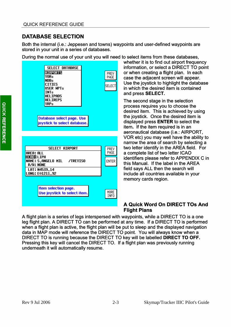
DATABASE SELECTION DATABASE SELECTION Both the internal (i.e.: Jeppesen and towns) waypoints and user-defined waypoints are stored in your unit in a series of databases. Both the internal (i.e.: Jeppesen and towns) waypoints and user-defined waypoints are stored in your unit in a series of databases. During the normal use of your unit you will need to select items from these databases,
whether it is to find out airport frequency information, or select a DIRECT TO point or when creating a flight plan. In each case the adjacent screen will appear. Use the joystick to highlight the database in which the desired item is contained and press SELECT.
During the normal use of your unit you will need to select items from these databases, whether it is to find out airport frequency information, or select a DIRECT TO point or when creating a flight plan. In each case the adjacent screen will appear. Use the joystick to highlight the database in which the desired item is contained and press SELECT.
Q
UIC
K R
EFEREN
CE
REFER
ENC
E
The second stage in the selection process requires you to choose the desired item. This is achieved by using the joystick. Once the desired item is displayed press ENTER to select the item. If the item required is in an aeronautical database (i.e.: AIRPORT, VOR etc) you may well have the ability to
The second stage in the selection process requires you to choose the desired item. This is achieved by using the joystick. Once the desired item is displayed press ENTER to select the item. If the item required is in an aeronautical database (i.e.: AIRPORT, VOR etc) you may well have the ability to
narrow the area of search by selecting a two letter identify in the AREA field. For a complete list of two letter ICAO identifiers please refer to APPENDIX C in this Manual. If the label in the AREA field says ALL then the search will include all countries available in your memory cards region.
narrow the area of search by selecting a two letter identify in the AREA field. For a complete list of two letter ICAO identifiers please refer to APPENDIX C in this Manual. If the label in the AREA field says ALL then the search will include all countries available in your memory cards region. A Quick Word On DIRECT TOs And Flight Plans A Quick Word On DIRECT TOs And Flight Plans
A flight plan is a series of legs interspersed with waypoints, while a DIRECT TO is a one leg flight plan. A DIRECT TO can be performed at any time. If a DIRECT TO is performed when a flight plan is active, the flight plan will be put to sleep and the displayed navigation data in MAP mode will reference the DIRECT TO point. You will always know when a DIRECT TO is running because the DIRECT TO key will be labelled DIRECT TO OFF. Pressing this key will cancel the DIRECT TO. If a flight plan was previously running underneath it will automatically resume.
A flight plan is a series of legs interspersed with waypoints, while a DIRECT TO is a one leg flight plan. A DIRECT TO can be performed at any time. If a DIRECT TO is performed when a flight plan is active, the flight plan will be put to sleep and the displayed navigation data in MAP mode will reference the DIRECT TO point. You will always know when a DIRECT TO is running because the DIRECT TO key will be labelled DIRECT TO OFF. Pressing this key will cancel the DIRECT TO. If a flight plan was previously running underneath it will automatically resume.
Rev 9 Jul 2006 2-3 Skymap/Tracker IIIC Pilot's Guide

QUICK REFERENCE GUIDE
VISUAL DIRECT TO AND DATA INTERROGATION In MAP mode use the joystick to move the pointer to the desired location, or obtain the latitude/longitude and bearing/distance from present position.
Q
UIC
K R
EFER
ENC
E
nd
ation
If you have a ground speed your Bendix/King unit will calculate the time to reach the tip of the on screen pointer. This information is displayed in the PETE (or Pointer ETE) field. If you wish to invoke the DIRECT TO function press the DIRECT TO key. The unit will then provide you with full navigation information to reach this point. Alternatively if you wish to obtain more
information on a specific data point, whether it is an airport, a section of controlled airspace or a beacon, move the pointer onto it and press the MORE INFO key. Once the pointer has been activated by pushing the joystick it will remain active for 30 seconds; after which time it will automatically reset if not moved. Alternatively you can force a reset by pressing RESET STICK DIRECT TO a Specific Latitude- And Longitude To perform a DIRECT TO a specified latitude/longitude press the DIRECT TO key in MAP mode when the joystick is not active.
Then press TEMP WPT and use the joystick to dial in the required latitude alongitude, followed by ENTER. The unit will then provide you with full naviginformation to reach this point.
Rev 9 Jul 2006 2-4 Skymap/Tracker IIIC Pilot's Guide

QUICK REFERENCE GUIDE
Manual DIRECT TO And Data Interrogation Provided the pointer is not active in MAP mode, press the DIRECT TO key. You will now be able to select the item from the database as explained in Database Selection in this section of the manual.
To activate the item as the DIRECT TO, press the SELECT key when the desired item is displayed. To get more information on the item press the MORE INFO key when the desired item is displayed. If you are running a DIRECT TO, you can discontinue the navigation by pressing the DIRECT TO OFF key.
Q
UIC
K R
EFEREN
CE
USER WAYPOINTS Editing/Creating A User Waypoint Manually From MAIN MENU select the FLIGHT PLAN key, followed by USER WPTS. Use the joystick to select the desired user waypoint number or name. Then press the EDIT key and use the joystick to edit the NAME, LAT and LONG fields.
The entire user waypoint can be deleted by pressing CLEAR WPT. If you only wish to delete data in a particular field, as opposed to the entire user waypoint, move the cursor over the field label (i.e. NAME, LAT, LONG) and press the CLEAR key. To save a user waypoint press SAVE & EXIT. Use the ABORT key to return to MAIN MENU without saving. The MARKER key configures the user waypoint as a special type of waypoint with an associated alarm. Marker waypoints are discussed in detail in the Flight Planning section of this manual.
Editing/Creating A User Waypoint Visually From MAIN MENU select the FLIGHT PLAN key, followed by USER WPTS. You may then use the joystick to select a specific user waypoint (either by number or name). Press the VIEW MAP key and the following screen will be shown with the previously selected user waypoint in the centre of the screen. If the previously selected user waypoint was empty your last position will be displayed.
Rev 9 Jul 2006 2-5 Skymap/Tracker IIIC Pilot's Guide

QUICK REFERENCE GUIDE
A user waypoint can then be created as a distance and bearing from the displayed position or as a latitude/longitude. Press ENTER WPT to save the user waypoint to the first available memory location. An unwanted user waypoint can be removed by moving the pointer over it and pressing the DELETE WPT key. If the user waypoint that you wish to delete is in a stored flight plan the message [PRESENT IN FLIGHT PLAN] will be displayed. A second press on the DELETE WPT key will however remove it, or you can move the joystick to cancel
the delete. Use the PREV PAGE key to save the changes and return to the User Waypoint screen.
Q
UIC
K R
EFER
ENC
E
Saving A User Waypoint In Flight A user waypoint can be saved quickly in flight by pressing NAV MENU in MAP mode followed by SAVE WPT. You will immediately be returned to MAP mode with your current position saved to the next available user waypoint memory location.
Rev 9 Jul 2006 2-6 Skymap/Tracker IIIC Pilot's Guide
QUICK REFERENCE GUIDE
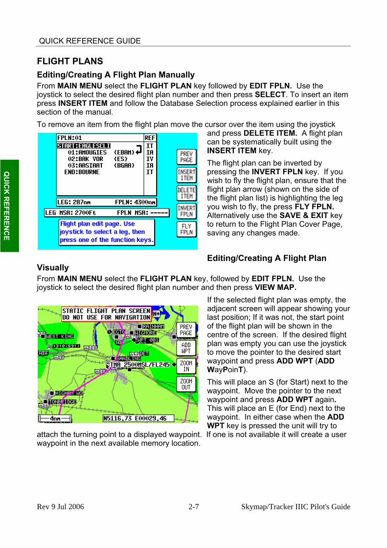
FLIGHT PLANS Editing/Creating A Flight Plan Manually From MAIN MENU select the FLIGHT PLAN key followed by EDIT FPLN. Use the joystick to select the desired flight plan number and then press SELECT. To insert an item press INSERT ITEM and follow the Database Selection process explained earlier in this section of the manual.
Q
UIC
K R
EFEREN
CE
To remove an item from the flight plan move the c
by you
diting/Creating A Flight Plan
ursor over the item using the joystick and press DELETE ITEM. A flight plan can be systematically built using the INSERT ITEM key. The flight plan can be invertedpressing the INVERT FPLN key. Ifwish to fly the flight plan, ensure that the flight plan arrow (shown on the side of the flight plan list) is highlighting the legyou wish to fly, the press FLY FPLN. Alternatively use the SAVE & EXIT keyto return to the Flight Plan Cover Page, saving any changes made.
EVisually From MAIN MENU select the FLIGHT PLAN key, followed by EDIT FPLN. Use the joystick to select the desired flight plan number and then press VIEW MAP.
If the selected flight plan was empty, the adjacent screen will appear showing your last position; If it was not, the start point of the flight plan will be shown in the centre of the screen. If the desired flight plan was empty you can use the joystick to move the pointer to the desired start waypoint and press ADD WPT (ADD WayPoinT). This will place an S (for Start) next to the waypoint. Move the pointer to the next waypoint and press ADD WPT again. This will place an E (for End) next to the waypoint. In either case when the ADD WPT key is pressed the unit will try to
attach the turning point to a displayed waypoint. If one is not available it will create a user waypoint in the next available memory location.
Rev 9 Jul 2006 2-7 Skymap/Tracker IIIC Pilot's Guide

QUICK REFERENCE GUIDE
To systematically create additional legs, draw a line from the waypoint marked (E), with the pointer, to the next waypoint and press ADD WPT again. You will notice that the last point in the flight plan will always be labelled (E). Once you have finished building the flight plan press PREV PAGE, to detach the pointer from the flight plan. This key, if pressed again will return to the screen entered from, saving any changes made.
Q
UIC
K R
EFER
ENC
E
INE r
ck o
the joystick to select the desired flight plan numb
itial leg that is to be flown and press
If you wish to add a new waypoint to a flight plan which you have stopped building, whether it is at the start, the end or the middle of the flight plan, you will need to highlight the appropriate point (i.e.: either the start waypoint (S), the end waypoint (E) or the leg line in which you wish to add a new waypoint). As soon as you do this, the ADD WPT or GRAB Lkey will appear. Press the ADD WPT oGRAB LINE key to join the pointer bato the flight plan line and then move it tthe new waypoint (NOTE: Key 2 reverts to ADD WPT). Once over the new waypoint press ADD WPT, otherwise press PREV PAGE to cancel this action. Unwanted waypoints
can be removed by pointing at them and pressing the DELETE WPT key. Use the PREV PAGE key to return to the screen entered from, saving any changes made.
Selecting A Flight Plan To Fly From MAIN MENU select the MAP key, followed by NAV MENU and FLIGHT PLAN. Use
er and then press the SELECT key. Ensure that the leg arrow is pointing at the inFLY FPLN. The unit will immediately revert to map mode with the navigation information showing, using the pre-selected MAP mode presentation
Rev 9 Jul 2006 2-8 Skymap/Tracker IIIC Pilot's Guide
QUICK REFERENCE GUIDE
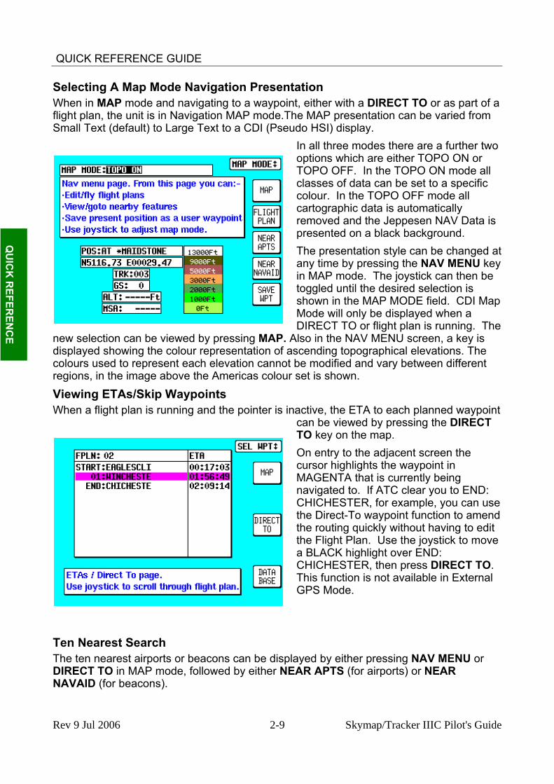
Selecting A Map Mode Navigation Presentation When in MAP mode and navigating to a waypoint, either with a DIRECT TO or as part of a flight plan, the unit is in Navigation MAP mode.The MAP presentation can be varied from Small Text (default) to Large Text to a CDI (Pseudo HSI) display.
Q
UIC
K R
EFEREN
CE
t
In all three modes there are a further two options which are either TOPO ON or TOPO OFF. In the TOPO ON mode all classes of data can be set to a specific colour. In the TOPO OFF mode all cartographic data is automatically removed and the Jeppesen NAV Data is presented on a black background. The presentation style can be changed aany time by pressing the NAV MENU keyin MAP mode. The joystick can then be toggled until the desired selection is shown in the MAP MODE field. CDI Map Mode will only be displayed when a DIRECT TO or flight plan is running. The
new selection can be viewed by pressing MAP. Also in the NAV MENU screen, a key is displayed showing the colour representation of ascending topographical elevations. The colours used to represent each elevation cannot be modified and vary between different regions, in the image above the Americas colour set is shown.
Viewing ETAs/Skip Waypoints When a flight plan is running and the pointer is inactive, the ETA to each planned waypoint
can be viewed by pressing the DIRECT TO key on the map. On entry to the adjacent screen the cursor highlights the waypoint in MAGENTA that is currently being navigated to. If ATC clear you to END: CHICHESTER, for example, you can use the Direct-To waypoint function to amend the routing quickly without having to edit the Flight Plan. Use the joystick to move a BLACK highlight over END: CHICHESTER, then press DIRECT TO. This function is not available in External GPS Mode.
Ten Nearest Search The ten nearest airports or beacons can be displayed by either pressing NAV MENU or DIRECT TO in MAP mode, followed by either NEAR APTS (for airports) or NEAR NAVAID (for beacons).
Rev 9 Jul 2006 2-9 Skymap/Tracker IIIC Pilot's Guide

QUICK REFERENCE GUIDE
The desired information will be presented dynamically as a bearing and distance from your present position. Any displayed item can be instantly navigated to by pressing the DIRECT TO key. Alternatively the MAP key can be used to return the user to MAP mode.
Q
UIC
K R
EFER
ENC
E
SETUP MAP FUNCTIONS When you receive the unit, it will be pre-programmed with default values for colour, language, map orientation etc. however it is possible to fully customise the map display for your specific operating requirements and taste.
The initial screen is reached by pressing SET UP in MAIN MENU, followed by MAP SETUP. The subsequent screens are reached by pressing the NEXT key.
On the initial page, each of the displayed features can be set using the joystick. The features are as follows: ORIENTATION: Set either in Track Up or North Up. AIRPORT NAME: Labels airports in MAP mode either with ICAO code, airport or city names. MAP UNITS: Sets all map units to ether nautical miles, statute miles or kilometres. If miles are selected, all lengths and altitudes will be reported in feet. If kilometres are selected, all lengths and altitudes will be reported in metres. COORD SYSTEM: Determines whether the unit operates with reference to Lat/Long, UTM or OSGB. DISPLAY: Sets orientation of the display into one of four configurations. LANGUAGE: Sets language to English, French, German or Spanish. MIN R/W LENGTH: Sets the minimum length of runway required for ten nearest airports.
Rev 9 Jul 2006 2-10 Skymap/Tracker IIIC Pilot's Guide
QUICK REFERENCE GUIDE
R/W SURFACE REQ: Sets the runway surface required for ten nearest airports. EXTENDED TRACK: Turns on or off the extended track line, which is drawn ahead of your present position in the direction of your present track. AUTO ZOOM: Turns on or off. When flying the last leg of a flight plan or when flying a DIRECT TO, as soon as the distance to the destination drops below ½ the scale bar setting, the unit automatically zooms. Auto Zoom can be disabled by simply pressing the ZOOM OUT key. AUTO DECLUTTER: Turns on or off. If a higher priority icon label (Airport) is found to clash with a lower priority icon label (City) already on the screen, the lower priority icon label will be removed.
Q
UIC
K R
EFEREN
CE
nitial
ressed
KEY BEEP: Turns the key beep on or off. LOGGING RATE: Sets the rate in seconds at which you log your position and loads it into a 2000 point cyclic memory. To log a specific flight use the CLEAR LOG key in the Clear Memory screen (please refer to the Clear Memory section below). The flight can be replayed in DEMO MODE (please refer to the selecting DEMO MODE section above). POSITION REF: Defines the reference to which your position is given in MAP MODE, either to all available data, VORs only or VORs and Airports only. AIRSPACE ALERT: As the aircraft is about to cross an airspace boundary, a warning appears on the screen in MAP mode.
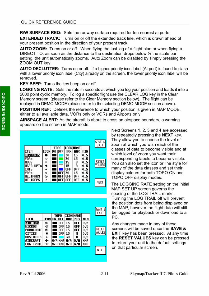
Next Screens 1, 2, 3 and 4 are accessed by repeatedly pressing the NEXT key. They allow you to choose the level of zoom at which you wish each of the classes of data to become visible and at which level of zoom you want their corresponding labels to become visible. You can also set the icon or line style for many of the data classes and set their display colours for both TOPO ON and TOPO OFF display modes. The LOGGING RATE setting on the iMAP SET UP screen governs the spacing of the LOG TRAIL marks. Turning the LOG TRAIL off will prevent the position dots from being displayed on the MAP, however the flight data will still be logged for playback or download to a PC. Any changes made in any of these screens will be saved once the SAVE & EXIT key has been pressed. At any time the RESET VALUES key can be pto return your unit to the default settings on that particular screen.
Rev 9 Jul 2006 2-11 Skymap/Tracker IIIC Pilot's Guide
QUICK REFERENCE GUIDE
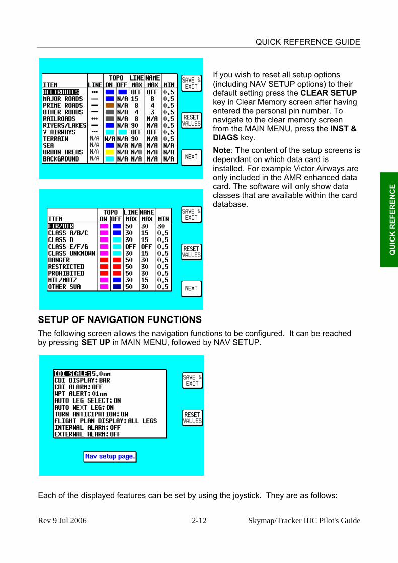
If you wish to reset all setup options (including NAV SETUP options) to their default setting press the CLEAR SETUP key in Clear Memory screen after having entered the personal pin number. To navigate to the clear memory screen from the MAIN MENU, press the INST & DIAGS key.
Q
UIC
K R
EFER
ENC
E
s Note: The content of the setup screens idependant on which data card is installed. For example Victor Airways are only included in the AMR enhanced data card. The software will only show data classes that are available within the card database.
SETUP OF NAVIGATION FUNCTIONS The following screen allows the navigation functions to be configured. It can be reached by pressing SET UP in MAIN MENU, followed by NAV SETUP.
Each of the displayed features can be set by using the joystick. They are as follows:
Rev 9 Jul 2006 2-12 Skymap/Tracker IIIC Pilot's Guide

QUICK REFERENCE GUIDE
CDI SCALE: Sets the full-scale deflection of displayed CDI to 0.3, 1.0, 2.5 or 5.0nm. CDI DISPLAY: Either turns the CDI display off, or sets it to either a numeric or bar display. CDI ALARM: Switches the CDI alarm on or off. When on, the alarm is activated at full-scale deflection. WPT ALERT: Sets the distance away from your destination waypoint at which you wish the audio and visual arrival alarms to be activated. This value is always in nautical miles. AUTO LEG SELECT: When switched on, the unit will automatically determine which is the most appropriate leg to fly when calling up a flight plan.
Q
UIC
K R
EFEREN
CE
e
AUTO NEXT LEG: When switched on, the unit will automatically sequence you on to the next waypoint in a flight plan when it has deemed that the current waypoint has been passed. When switched off the user will be expected to press the NEXT LEG key in MAP mode to sequence on to the next waypoint in the flight plan. TURN ANTICIPATION: Turn Anticipation provides navigation along a curved path segment to ensure a smooth transition between two adjacent legs in the flight plan at higher groundspeeds. FLIGHT PLAN DISPLAY: Allows a choice of displaying the full flight plan or just the active leg on the map screen. INTERNAL (ARRIVAL and CDI) ALARM: These alarms can be switched on or off. EXTERNAL (ARRIVAL and CDI) ALARM: These alarms can be switched on or off. Any changes made in this screen will be saved once the SAVE & EXIT key has been pressed. At any time the RESET VALUES key can be pressed to return your unit to the default settings. If you wish to reset all setup options (including MAP SETUP options) to their default setting press the CLEAR SETUP key in the Clear Memory screen.
CLEAR MEMORY To clear down specific parts of your units’ memory press SET UP in MAIN MENU, followed by INST & DIAGS and CLEAR MEMORY. You will then be asked to enter you’re your PIN (unit default is 1-2-3-4). You are now in the Clear Memory screen.
Each block of memory in your unit can bcleared down individually. CLEAR FPLNs will remove all your flight plans. CLEAR WPTS will remove all your user waypoints. CLEAR SETUP will restore all the default settings in MAP SETUP and NAV SETUP. CLEAR LOG will clear the last flight information, the 2000 logged flight data points and all running timers.
Rev 9 Jul 2006 2-13 Skymap/Tracker IIIC Pilot's Guide

QUICK REFERENCE GUIDE
Q
UIC
K R
EFER
ENC
E
THIS PAGE INTENTIONALLY BLANK
Rev 9 Jul 2006 2-14 Skymap/Tracker IIIC Pilot's Guide

DETAILED OPERATION
SECTION 3 DETAILED OPERATION SECTION 3 DETAILED OPERATION TITLE AND HELP SCREENS TITLE AND HELP SCREENS To switch the unit on, rotate the On/Off/Brightness control fully clockwise. To switch the unit on, rotate the On/Off/Brightness control fully clockwise. Your unit produces a variety of tones and alarms to assist you in correct operation. At this stage only two types of tone are relevant. These are: Your unit produces a variety of tones and alarms to assist you in correct operation. At this stage only two types of tone are relevant. These are:
• One short beep sounds when you press a valid key. • One short beep sounds when you press a valid key.
• Two short beeps sound when you press a key that is not assigned. • Two short beeps sound when you press a key that is not assigned. In the following screen images the numbers shown adjacent to the key positions indicate the screen number activated when that key is pressed. In the following screen images the numbers shown adjacent to the key positions indicate the screen number activated when that key is pressed.
D
ETAILED
OPER
ATIO
N
ILED O
PERA
TION
Screen 1: Title Screen Screen 1: Title Screen
The Title Screen appears each time the unit is switched on, after the Jeppesen® database expiry date has been acknowledged. The Title Screen appears each time the unit is switched on, after the Jeppesen® database expiry date has been acknowledged.
Key 1 calls Screen 2, which is the Main Menu Screen. Key 1 calls Screen 2, which is the Main Menu Screen. Key 2 calls Screen 7, which is the Flight Planning Mode Cover Screen. Key 2 calls Screen 7, which is the Flight Planning Mode Cover Screen. Key 3 calls Screen 20, which is the Demo Mode Setup Screen. (If, since being
switched on, the unit has received valid fix information from the internal GPS receiver (Skymap IIIC) or from an external device (Tracker IIIC), Key 3 DEMO MODE will for safety reasons be blanked and disabled.) This is the only Screen on which Demo Mode can be activated.
Key 3 calls Screen 20, which is the Demo Mode Setup Screen. (If, since being switched on, the unit has received valid fix information from the internal GPS receiver (Skymap IIIC) or from an external device (Tracker IIIC), Key 3 DEMO MODE will for safety reasons be blanked and disabled.) This is the only Screen on which Demo Mode can be activated.
Key 4 calls Screen 21, which is the Setup Cover Screen. Key 4 calls Screen 21, which is the Setup Cover Screen. Key 5 calls Screen 38, which is the Map Mode Screen. Key 5 calls Screen 38, which is the Map Mode Screen.
To switch the unit off, rotate the On/Off/Brightness control fully counter clockwise. To switch the unit off, rotate the On/Off/Brightness control fully counter clockwise.
WARNING: Do not force the control knob past its end stops.
Rev 9 Jul 2006 3-1 Skymap/Tracker IIIC Pilot's Guide
DETAILED OPERATION
Self Test and Initialisation When the Title Screen is initially displayed, the unit carries out a series of internal check routines automatically. These are:
1. Verification that the unit has been factory initialised. This consists of a check to see if there is a special code in NVM. If there is no initialisation code in the NVM a message saying UNIT NOT INITIALISED will be printed across the centre of the Screen and the unit will be totally disabled. This is a security feature, safeguarding against theft of the unit and attempted erasure of your PIN from the NVM. (If your unit is stolen and the NVM is erased or replaced in an attempt to reset the PIN, the thief will still not be able to use or sell the unit because these special high security factory initialisation codes will be missing.)
2. A check for RAM corruption. If RAM has been lost or corrupted due to a severe ‘glitch’ or loss of power in the memory battery a RAM clear will be performed on the affected areas and Screen 51, Ram Lost Warning Screen, will be displayed (Refer to APPENDIX B ).
3. A check of the internal Lithium battery voltage. If the internal battery voltage is low, Screen 52, Internal Battery Warning Screen, will be displayed (Refer to APPENDIX B ).
4. A check to see whether the Automatic Power-On Lock function has been enabled (see Screen 26 for further details). If it is enabled, Screen 54, Power On Security PIN Entry Screen, will be displayed after 5 seconds (or if any Key is pressed before this). If when switched on it is found that three unsuccessful attempts have been made to enter the Unlock PIN, Screen 55, Lockout Screen, will be displayed (Refer to APPENDIX B ).
D
ETA
ILED
OPE
RA
TIO
N
5. A check to see if a new memory card has been fitted. This involves comparing the software version number held in NVM with that of the current memory Card. If a change of card is detected, the integrity of all flight plans will be checked and if any discrepancies are found Screen 56, Flight Plan Change Warning Screen, will be displayed (Refer to APPENDIX B ).
6. If the unit is a Skymap IIIC the GPS receiver circuitry will be tested and if any problems are found, a NO REPLY message will be indicated in the STATUS field of Screen 3, GPS Status Screen.
If the unit passes all checks 1 to 6 above no warnings will be given
Rev 9 Jul 2006 3-2 Skymap/Tracker IIIC Pilot's Guide

DETAILED OPERATION
Main Menu Screen
Screen 2: Main Menu Screen
On Skymap IIIC units, Key 1 calls Screen 3, which is the GPS Status Screen. On Tracker IIIC units, Key 1 is labelled DATA IN/OUT and will cause Screen 35, Data input/output Setup and Test Screen, to be displayed. Key 2 calls Screen 7, which is the Flight Planning Mode Cover Screen. Key 3 will read NOTE PAD if DEMO MODE was not selected on Screen 1. Pressing Key 3 when labelled NOTE PAD will call screen 62, which is the NOTE PAD display screen and will also give access to Screen 57, which is the E6-B Calculator Cover Screen (Refer to Section on E6-B Calculator). If Demo Mode has previously been activated, Key 3 will read DEMO OFF. Pressing DEMO OFF will then switch Demo Mode off and return to Screen 2 with Key 3 reading NOTE PAD. Key 4 calls Screen 21, which is the Setup Cover Screen. Key 5 calls Screen 38 or 47, which are MAP Mode and MAP Mode with NAV Information Screens.
D
ETAILED
OPER
ATIO
N
Note Pad Screen The Note Pad Screen (Screen 62) is accessed by pressing Key 3 on Screen 2, Main Menu Screen.
Screen 62: Notepad Screen
Rev 9 Jul 2006 3-3 Skymap/Tracker IIIC Pilot's Guide

DETAILED OPERATION
The Note Pad function allows you to load up to 4000 characters of text into your GPS unit from a personal computer running the ‘Flight Manager’ flight planning software, and then recalls the text on this screen during flight. The Note Pad text can contain any information you want. Typical uses include checklists, en-route weather downloaded before the flight from DUATS, special instruction for an unfamiliar destination etc. Using the 'Flight Manager' software you can prepare and store a library of Note Pad files and load the relevant one into your Bendix/King unit to suit your day's flying. Screen 62 also gives access to the E6-B calculator screens.
D
ETA
ILED
OPE
RA
TIO
N
Rev 9 Jul 2006 3-4 Skymap/Tracker IIIC Pilot's Guide

DETAILED OPERATION
GPS STATUS SCREENS (SKYMAP IIIC ONLY)
Screen 3: GPS Status Screen
Pressing Key 1, GPS STATUS, in Main Menu, accesses this Screen. The GPS Status Screen will display the receiver status. This can be any of the following:
BAD ALMANAC <3 SATS DIFFERENTIAL ACQUIRING 2D FIX 3D FIX POOR DOP POS PROP
D
ETAILED
OPER
ATIO
N
The meanings of these displays are: BAD ALMANAC means the GPS receiver's information concerning satellite positions is out of date. If this occurs the unit should be left alone with the antenna connected and in view of the sky for approximately 15 minutes during which period it will automatically lock onto a satellite and load an up-to-date almanac. <3 SATS means that according to the current information available, there are less than three satellites in view and a fix can not be calculated. This message is very rarely displayed. DIFFERENTIAL This word will be displayed in conjunction with 2D FIX or 3D FIX and means that the Skymap IIIC has a fix and is also receiving differential correction signals from an external source. (Refer to APPENDIX E for further details concerning differential operation.) ACQUIRING means the unit is currently searching for satellites or is loading information from one or more satellites. 2D FIX means the unit is calculating position in two dimensions (i.e. latitude and longitude only, with no height information). 3D FIX means that the unit is calculating position in three dimensions and can give latitude, longitude and height information. POOR DOP means that the unit is unable to calculate position owing to the poor geometry of the visible satellites. (DOP stands for Dilution of Precision.) POS PROP means that navigation has been temporarily lost and the Skymap IIIC is dead-reckoning (or propagating) its position based on the last known position, track and ground speed. It will not dead-reckon for more than a few seconds at a time.
Rev 9 Jul 2006 3-5 Skymap/Tracker IIIC Pilot's Guide

DETAILED OPERATION
Other information that is displayed on this Screen includes: DOP (Dilution of Precision), This is a number between 00.0 and 99.0 that represents the dilution of quality of the calculated fix due to satellite geometry. 00.0 is best, 99.9 is worst. If this figure is greater than 5.0, performance of the system is likely to be degraded because some of the visible satellites appear too close to each other. DOP is calculated from the angular separation between the various visible satellites. Greater separation results in better fix geometry and a lower DOP. (This DOP figure is not measured in any specific units.) UTC/DATE, which is Universal or Greenwich Mean Time and Date. LOCAL OFFSET, which is the difference between UTC and local time. LOCAL TIME, which is calculated by adding Local Offset to UTC. LAST FIX. If the unit does not have a current valid fix, this is the position at which it last had a fix. If the unit has a fix, this is the present position. SATS (eight or twelve satellite numbers depending model), SIGS (signal strength for each satellite) and STAT (status of each satellite). Each satellite has a PRN (Pseudo Random Noise) or identification number. The satellite PRN numbers are displayed in a line beside the word SATS. The two-digit number under each PRN number is an indication of the signal strength being received from that satellite expressed in terms of a percentage. Best is 99, worst is 00. These numbers can be used for finding and eliminating electrical interference. Readings of 60 and above indicate a good installation.
D
ETA
ILED
OPE
RA
TIO
N
Under each signal strength number is a two-character code. These indicate the status of each satellite. These codes are: CS, CA, AS, FA, BD, MD, TA, EA, and AP. These relate to the eight possible receiver modes and are detailed below. CS: Code Search. This is the receiver's initial stage in acquiring a satellite. It means that the receiver is trying to match its internal code to the satellite signal. CA: Code Acquire. This means the satellite code has been received and matched to the receiver-generated code. AS: AGC Set. This means the satellite strength has been assessed and the Automatic Gain Control has been set. FA: Frequency Acquire. This means the receiver has correctly locked onto the satellite data frequency. BD: Bit Sync Detect. This means the receiver is synchronised with the satellite's data bit stream. MD: Message Detect. This means the receiver is synchronised with the satellite's message stream. TA: Time Available. This means the satellite is fully locked in and has sent down UTC time and date information to the receiver. EA: Ephemeris Acquire. This means the receiver is reading the constellation health status message from the satellite. This usually takes around two minutes and is a function that is performed in the background even if the receiver has a fix. AP: Available for Position. This means the satellite is fully locked in and tested and can be used for calculating position. A minimum of three satellites are necessary for a 2D fix.
Rev 9 Jul 2006 3-6 Skymap/Tracker IIIC Pilot's Guide
DETAILED OPERATION
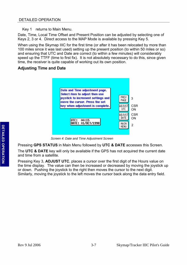
Key 1 returns to Main Menu. Date, Time, Local Time Offset and Present Position can be adjusted by selecting one of Keys 2, 3 or 4. Direct access to the MAP Mode is available by pressing Key 5. When using the Skymap IIIC for the first time (or after it has been relocated by more than 100 miles since it was last used) setting up the present position (to within 50 miles or so) and ensuring that UTC and Date are correct (to within a few minutes) will considerably speed up the TTFF (time to first fix). It is not absolutely necessary to do this, since given time, the receiver is quite capable of working out its own position.
Adjusting Time and Date
Screen 4: Date and Time Adjustment Screen
D
ETAILED
OPER
ATIO
N
Pressing GPS STATUS in Main Menu followed by UTC & DATE accesses this Screen. The UTC & DATE key will only be available if the GPS has not acquired the current date and time from a satellite. Pressing Key 3, ADJUST UTC, places a cursor over the first digit of the Hours value on the time display. The value can then be increased or decreased by moving the joystick up or down. Pushing the joystick to the right then moves the cursor to the next digit. Similarly, moving the joystick to the left moves the cursor back along the data entry field.
Rev 9 Jul 2006 3-7 Skymap/Tracker IIIC Pilot's Guide

DETAILED OPERATION
Screen 4 (Cursor On): Date and Time Adjustment Screen
When the time is adjusted, the information will only be saved if you press Key 1 SET as illustrated below.
D
ETA
ILED
OPE
RA
TIO
N Pressing Key 4 puts a cursor onto the Date entry field. The date is adjusted in the same
way as time. With the cursor over the Month when the joystick is moved up or down, the first three characters of each month are scrolled together i.e. JAN, FEB, MAR, APR etc. Adjusting the year works in the same way. Your Bendix/King unit is fully Year 2000 compliant. The Time and Date will be automatically corrected as soon as the first satellite reaches TA (time available) status. If any satellite is already at status TA or above, user inputs of time and date will be ignored.
Setting Local Time Offset
Screen 5: Local Time Offset Screen
Pressing GPS STATUS in Main Menu, followed by LOCAL OFFSET, accesses this Screen. When this Screen initially appears a cursor will be active in the data entry field.
Rev 9 Jul 2006 3-8 Skymap/Tracker IIIC Pilot's Guide

DETAILED OPERATION
The hour’s value can be adjusted between the limits of +12 and -12 by using the joystick. The cursor can then be moved to the right to adjust the minutes to one of two values, 00 or 30. Only after pressing Key 1, SET is the information saved and the display will revert to Screen 3, GPS Status Screen. The local offset is held in RAM and added to UTC time when calculating ETA's. Default value is +00:00. It is important to set local offset correctly to ensure any ETA’s given are correct. Setting Present Position
Screen 6: Present Position Setup Screen
D
ETAILED
OPER
ATIO
N
Pressing GPS STATUS in Main Menu, followed by SET POSN, accesses this Screen. The SET POSN key will not be available if the GPS has acquired a fix. On entry to this Screen a cursor is positioned over the first character of the latitude as shown above. The joystick can then be used to increment or decrement values and to move the cursor right and left. Alternatively you can press Key 4 VIEW MAP and using the joystick, simply point at your present position.
Rev 9 Jul 2006 3-9 Skymap/Tracker IIIC Pilot's Guide

DETAILED OPERATION
Screen 10A: View Map Screen
When Screen 10A is displayed you can zoom in or out using Keys 2 or 3. By using the joystick you can ‘bump’ the borders of the map window to view anywhere in the world. The POS: box at the bottom of the screen displays the latitude and longitude of the pointer.
D
ETA
ILED
OPE
RA
TIO
N Once you have the joystick pointing at your present location, press Key 5 SET POSN to
return to Screen 3, GPS Status Screen. The pointer latitude and longitude will have become the LAST FIXED POSITION on Screen 3. When new values for latitude and longitude have been selected numerically, pressing Key 1 SET will enter the new latitude and longitude and revert to Screen 3. If the unit is receiving sufficient satellite signals to calculate a fix, user-entered latitude and longitude will be ignored. Keys 3 and 4 give direct access to Time and Date adjustment.
Rev 9 Jul 2006 3-10 Skymap/Tracker IIIC Pilot's Guide

DETAILED OPERATION
DATA INPUT The Tracker IIIC has no internal GPS receiver and so requires a data input from a separate GPS or LORAN unit in order to function in Map Mode. If required, the Skymap IIIC can also be run in Tracker mode using an external GPS or LORAN unit. (Refer to Data In/Out in the Setup Screens Section of the Manual). The following text is valid for Skymap IIIC also if set to Tracker mode. Your Tracker IIIC unit is supplied complete with a power/data cable, which has red, blue, yellow and green cores and a braided screen. The red and blue cores are for connection to an external DC power supply rated between 10V and 33V. The yellow core is the data input cable for connection to your GPS or LORAN. To operate correctly Tracker IIIC requires a 1200, 4800 or 9600 baud NMEA 0183 data sentence containing latitude, longitude, track, and ground speed information. This can take the form of a single RMC sentence or a combination of GGA and VTG sentences. Alternatively a 1200, 4800 or 9600 baud Trimble TNL, Garmin AIU or King equivalent ARNAV R-30 sentence may be used. A third alternative data input is the Northstar M3 binary data format at 1200 baud. To connect the Tracker IIIC to the GPS or LORAN source unit strip the outer cable insulation back a short way and pull back the screening braid to reveal the four inner plastic covered cores. The screening braid of the cable should be twisted into a single core. The red and blue cables should be connected to an external power supply (red is +ve). The screening braid and blue cable core should be connected to the same –ve power supply as the GPS/LORAN. This provides a return path for the data output. You are now ready to make data connection to your GPS or LORAN unit. The input is RS232, RS422 and NMEA 0183 compatible.
D
ETAILED
OPER
ATIO
N
When connecting to an RS232 or NMEA device, yellow should go to DATA OUT (A line). When connecting to an RS422 device, yellow should go to TX-. Do not connect to RS422 TX +. Example 1: To connect to a Bendix/King KLN89/89B (RS232), connect the yellow core of the Tracker IIIC cable to pin 2 of the KLN device. Connect the blue core and screen of the Tracker IIIC cable are connected to the to the same –ve supply or A/C ground as pin 14 of the KLN device. Example 2: To connect to a Bendix/King KLN90/90B (RS232), connect the yellow core of the Tracker IIIC cable to pin 13 of the KLN device. Ensure the blue core and screen of the Tracker IIIC cable are connected to the to the same –ve supply or A/C ground as pin 27 of the KLN device. Example 3: To connect to a Garmin GPS150/155 (RS232), connect the yellow core of the Tracker IIIC cable to pin 19 (channel 1) or pin 24 (channel 2) of the Garmin device. Ensure the blue core and screen of the Tracker IIIC cable are connected to the to the same –ve supply or A/C ground as pin 26 of the Garmin device. Example 4: To connect to a stand-alone Pronav or Garmin GPS 100 (NMEA), connect the yellow core of the Tracker IIIC cable to the yellow core of the power/data cable. Ensure the blue core and screen of the Tracker IIIC cable are connected to the same –ve supply or A/C ground as the black core of the power/data cable of the GPS. Once you have made the physical connection to your GPS or LORAN it is essential to select an appropriate data output. This can be done by referring to the manual for your GPS/LORAN and choosing an option that corresponds to one of the compatible data input
Rev 9 Jul 2006 3-11 Skymap/Tracker IIIC Pilot's Guide

DETAILED OPERATION
types listed above. Once a suitable data output type has been selected on your GPS/LORAN and it has a fix, switch on your Tracker IIIC and from the Main Menu Screen, press Key 1, DATA IN/OUT. Screen 35(T), Data input/output Setup and Test Screen will be displayed.
Screen 35(T): Data Input/Output Setup and Test Screen
If your GPS or LORAN is correctly connected, switched on and outputting data, your Tracker IIIC will automatically start to read and decode the incoming data. There is no need to set an input type on the Tracker IIIC as this is done automatically.
D
ETA
ILED
OPE
RA
TIO
N
After a few seconds if data is being received, the word YES will appear next to the RECEIVING NAV DATA: heading. The type of data being received will then be displayed beside the DATA INPUT: heading. If the data being received contains valid fix information (i.e. your GPS or LORAN has a fix) the word YES will appear next to the NAV DATA VALID: heading. Once the unit is receiving and validating the incoming data you are ready to navigate using Tracker IIIC 's advanced features. Press Key 1, PREV PAGE, to return to either the Installation & diagnostics Cover Screen or the Main Menu Screen.
Rev 9 Jul 2006 3-12 Skymap/Tracker IIIC Pilot's Guide
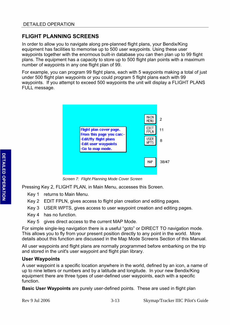
DETAILED OPERATION
FLIGHT PLANNING SCREENS In order to allow you to navigate along pre-planned flight plans, your Bendix/King equipment has facilities to memorise up to 500 user waypoints. Using these user waypoints together with the enormous built-in database you can then plan up to 99 flight plans. The equipment has a capacity to store up to 500 flight plan points with a maximum number of waypoints in any one flight plan of 99. For example, you can program 99 flight plans, each with 5 waypoints making a total of just under 500 flight plan waypoints or you could program 5 flight plans each with 99 waypoints. If you attempt to exceed 500 waypoints the unit will display a FLIGHT PLANS FULL message.
D
ETAILED
OPER
ATIO
N
Screen 7: Flight Planning Mode Cover Screen
Pressing Key 2, FLIGHT PLAN, in Main Menu, accesses this Screen. Key 1 returns to Main Menu. Key 2 EDIT FPLN, gives access to flight plan creation and editing pages. Key 3 USER WPTS, gives access to user waypoint creation and editing pages. Key 4 has no function. Key 5 gives direct access to the current MAP Mode.
For simple single-leg navigation there is a useful “goto” or DIRECT TO navigation mode. This allows you to fly from your present position directly to any point in the world. More details about this function are discussed in the Map Mode Screens Section of this Manual. All user waypoints and flight plans are normally programmed before embarking on the trip and stored in the unit's user waypoint and flight plan library.
User Waypoints A user waypoint is a specific location anywhere in the world, defined by an icon, a name of up to nine letters or numbers and by a latitude and longitude. In your new Bendix/King equipment there are three types of user-defined user waypoints, each with a specific function. Basic User Waypoints are purely user-defined points. These are used in flight plan
Rev 9 Jul 2006 3-13 Skymap/Tracker IIIC Pilot's Guide
DETAILED OPERATION
building, along with data points from the internal database, or simply to add personalised points to your map. A large choice of icon styles are available. Marker User Waypoints are also user-defined waypoints. These can be configured to act as alarm trigger markers. For example, say you are flying a flight plan and you know you have to make a radio call or initiate a climb at a specific point. A Marker User Waypoint can be positioned at that location (but not included in the flight plan) and be set up to trigger an alarm. If a user waypoint is to be used as an alarm trigger, when it is programmed it is given the name MARKERX.X (by pressing the MARKER key). The word MARKER here notifies the software that this user waypoint is to be used as a marker point only and that no name is to be printed next to the user waypoint icon on the map. The X.X specifies the alarm trigger distance between 0.1nm and 9.9nm. The default is 1.0nm. A circle of the specified radius will appear around the marker point on the map. Whilst the Bendix/King software is searching to locate the nearest items for conventional position reporting, if it pulls up a user waypoint named MARKERX.X, it will continuously compare the distance from the present position to the Marker waypoint with the value X.X. When the distance to the Marker becomes less than or equal to X.X then an audible alarm will be triggered. A box will also appear at the top of the screen showing MARKER IMMINENT. Key 5 will change to ALARM OFF and when pressed, will silence the audio alarm and remove the MARKER IMMINENT message. Should you wish a Marker waypoint to have a name next to it for reference, you simply program a Basic User Waypoint with the same co-ordinates as the Marker and give this one a conventional name. The User and Marker waypoint icons would then be superimposed on each other, resulting in a single, named, waypoint.
D
ETA
ILED
OPE
RA
TIO
N
User Defined Airports. Owing to the fact that many private and unlicensed airports are not included within the Jeppesen database contained within your unit, you have the opportunity to program up to 25 of your own USER DEFINED AIRPORTS. User waypoints numbered 101 - 125 have been reserved for this purpose and whenever any of these is selected for editing on Screen 8, User Waypoint Viewer Screen, then Screen 8A will be displayed instead. This Screen allows the insertion of additional information, so permitting 25 user waypoints to become user-defined airports. These will be shown on the map pages with an airport icon instead of a user waypoint icon. The user-defined airports will also be included in the ten nearest airports search on Screen 43, Ten Nearest Airports Screen, and will receive equal priority with other database airports for position reporting purposes. On Screen 39, MAP Mode with Joystick Active Screen, if the pointer is placed over a user-defined airport and the MORE INFO Key is pressed, Screen 40, Map Mode Airport Information Screen, will be displayed with the data you have entered being displayed.
Rev 9 Jul 2006 3-14 Skymap/Tracker IIIC Pilot's Guide

DETAILED OPERATION
Viewing User Waypoints
Screen 8: User Waypoint Viewer Screen
Pressing FLIGHT PLAN in Main Menu, followed by USER WPTS, accesses this Screen. When this Screen appears a cursor will be seen positioned over the WPT field. Use the joystick to increment or decrement the user waypoint number. (Holding the joystick up or down will increase the speed of these changes.) Alternatively the joystick can be used to select a user waypoint alphabetically by name in a similar fashion by moving the cursor down to the NAME: field.
D
ETAILED
OPER
ATIO
N
As each user waypoint is selected, the name, latitude, longitude, icon and position fields are updated. Empty user waypoints will be shown with dashes in the latitude and longitude fields and the default icon (see Screen 22A, Point Features Data Class Setup Screen, in the Setup Screens Section of this Manual for details on setting up the default icon style). As each user waypoint is selected, all stored flight plans are automatically checked to see if that user waypoint is being used in any current flight plan. If the user waypoint is found within any of the flight plans, the words [FPLN LINK] will be printed next to the user waypoint number. It is necessary to think carefully before editing any user waypoint marked FPLN LINK since any changes you make to the user waypoint may also affect one or more of the programmed flight plans. If a user waypoint marked FPLN LINK is selected for editing and the Name only is changed, the new name will be copied over to the relevant parts of the flight plan list. If the name is left the same and the Latitude and/or Longitude only is changed, the new details will also be copied into the flight plan list. However, if the Name is changed, along with either the Latitude or Longitude the user waypoint will be treated as completely new and the details will not be copied to the flight plan list. This would result in your being left with waypoints in your flight plans that do not exist as user waypoints. This can be beneficial in some cases as it makes it possible to double the number of user points in the system to 1000, but it is essential to understand this feature thoroughly and to use it carefully. Once a user waypoint has been selected, Key 2 gives access to the Manual User Waypoint Editing facilities. Key 1 will return to the main Flight Planning Mode Cover Screen. Key 3, NEW WPT shall invoke the Manual User waypoint editing with the next available empty waypoint. NOTE: Key 3 is blank if the waypoint database is full. Key 5
Rev 9 Jul 2006 3-15 Skymap/Tracker IIIC Pilot's Guide

DETAILED OPERATION
displays Screen 10, which is the Graphical User Waypoint Editing Screen. This shows a map on which the selected user waypoint is central. If the selected user waypoint is empty, the map will default to the last fix position.
Manual User Waypoint Editing
Screen 9: Manual User Waypoint Edit Screen
Pressing FLIGHT PLAN in Main Menu, followed by USER WPTS and EDIT, accesses this Screen. On entry to this Screen a cursor appears over the word NAME. The cursor can be moved up and down between NAME, LAT, LONG and ICON using the joystick. The joystick is used to move the cursor to the right so that the user waypoint name, latitude, longitude and icon type can be entered or amended, again by using the joystick.
D
ETA
ILED
OPE
RA
TIO
N
When the cursor is moved to the right after the last character in a line the cursor will move to the next line heading. i.e. from the last character in the name, the cursor will go to the word LAT and similarly from the last digit of the longitude it will go to the word ICON. If you want to use the selected user waypoint as a marker as described previously, pressing Key 2, MARKER, will automatically write the word MARKER1.0 into the name field. You can then move the cursor across using the joystick and alter the distance and fill in the latitude and longitude. If you want to delete an existing user waypoint, press Key 4. If you want to delete just the data entry field that the cursor is positioned over, press Key 3, CLEAR. When the desired alterations have all been made, touching Key 1, SAVE & EXIT, will enter the revised data and return you to Screen 8, User Waypoint Viewer Screen. Alternatively, touching Key 5, ABORT, will return you to Screen 8 without modifying the user waypoint information, cancelling all the changes you have made.
Rev 9 Jul 2006 3-16 Skymap/Tracker IIIC Pilot's Guide

DETAILED OPERATION
Graphical User Waypoint Editing
Screen 10: View and Edit User Waypoints on the Map Screen
When this Screen first appears, after pressing VIEW MAP on Screen 8, User Waypoint Viewer Screen, the selected user waypoint will be centrally positioned. The joystick can be used to move the pointer. The screen window can be moved around to display other areas of the map by “bumping” the screen borders left, right, up or down with the pointer. If you need to “bump” the screen over a large distance you will find it quicker and easier to zoom out first, move across the map as required, then zoom back in. In order to make these moves swiftly, not all details of the map are shown on screen until the joystick is released.
D
ETAILED
OPER
ATIO
N
Distance and bearing boxes below the map show distance and bearing from the selected user waypoint (or the last user waypoint entered) to the pointer. This feature allows you easily to enter new user waypoints as a distance and bearing from a previously entered user waypoint. New user waypoints can be created wherever the pointer is placed, simply by pressing Key 2, ENTER WPT. Positioning the pointer directly over an icon and then pressing Key 5, DELETE WPT, will delete existing user waypoints. Should you attempt to delete a user waypoint that is being used in a stored flight plan, the [PRESENT IN FLIGHT PLAN] message box will be displayed and the user waypoint will NOT be deleted. Pressing Key 5, DELETE WPT, a second time will then delete the user waypoint. Alternatively if you move the joystick, the [PRESENT IN FPLN] message will be removed without deleting the user waypoint. Key 1, PREV PAGE returns to the screen entered from, saving any changes made. Each new user waypoint graphically created on the map will automatically be given the next available user waypoint number as a temporary name and the default icon but you can alter the name and icon later by using Screen 9, Manual User Waypoint Edit Screen.
Rev 9 Jul 2006 3-17 Skymap/Tracker IIIC Pilot's Guide
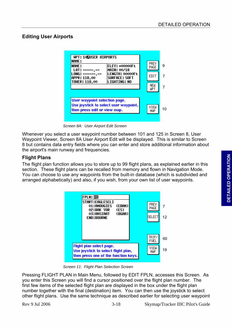
DETAILED OPERATION
Editing User Airports
Screen 8A: User Airport Edit Screen
Whenever you select a user waypoint number between 101 and 125 in Screen 8, User Waypoint Viewer, Screen 8A User Airport Edit will be displayed. This is similar to Screen 8 but contains data entry fields where you can enter and store additional information about the airport's main runway and frequencies.
D
ETA
ILED
OPE
RA
TIO
N
Flight Plans The flight plan function allows you to store up to 99 flight plans, as explained earlier in this section. These flight plans can be recalled from memory and flown in Navigation Mode. You can choose to use any waypoints from the built-in database (which is subdivided and arranged alphabetically) and also, if you wish, from your own list of user waypoints.
Screen 11: Flight Plan Selection Screen
Pressing FLIGHT PLAN in Main Menu, followed by EDIT FPLN, accesses this Screen. As you enter this Screen you will find a cursor positioned over the flight plan number. The first few items of the selected flight plan are displayed in the box under the flight plan number together with the final (destination) item. You can then use the joystick to select other flight plans. Use the same technique as described earlier for selecting user waypoint
Rev 9 Jul 2006 3-18 Skymap/Tracker IIIC Pilot's Guide

DETAILED OPERATION
numbers. Once you have selected the flight plan you wish to edit, pressing Key 2, will allow you to manually edit it. Key 1, PREV PAGE, returns you to the Flight Planning Mode Cover Screen. Key 5, VIEW MAP, calls Screen 19, enabling you to edit the selected flight plan graphically on the map. Key 4, TRIP/FUEL gives access to the trip and fuel planning function. For more information on this function please refer to the Trip/Fuel Planning information in the E6B Calculator Section of this Manual. If you access the above Flight Plan Selection Screen while a flight plan is active, the active flight plan number is automatically displayed and you will find Key 5 has changed to FPLN OFF and Key 2 is blank. As a safety measure the system will not allow you to edit the active flight plan directly unless you touch Key 5, FPLN OFF. This will switch the flight plan out of active status and re-enable Key 2 allowing you to edit what was until then the active flight plan.
Manual Flight Plan Building and Editing
Screen 12: Flight Plan Program/Edit Screen
D
ETAILED
OPER
ATIO
N
This Screen can be accessed either through the Flight Planning Mode Cover Screen (by pressing FLIGHT PLAN in Main Menu followed by EDIT FPLN and SELECT) or through the NAV Menu Cover Screen (by pressing NAV MENU in MAP Mode followed by FLIGHT PLAN). For more information on the second form of entry to this Screen see Screen 41, NAV Menu Cover Screen, in the NAV Menu Screens Section of this Manual. When you enter this Screen you will find a cursor positioned over the first item in the chosen flight plan. By using the joystick, you can move the cursor up or down. This enables you to scroll in either direction through the entire flight plan in the display box. Next to each waypoint in the column headed REF you will see a two-character code, which gives the database origin of each point in the flight plan. The meanings of these codes are as follows: IA (Internal Jeppesen Airports); IV (Internal Jeppesen VOR’s); IN (Internal Jeppesen NDB’s); IR (Internal Jeppesen Runways); IT (Internal Towns); II (Internal Jeppesen Intersections/Approach Waypoints); WP (current user waypoint if user waypoint link is present); OW (Old user waypoint if user waypoint link has been broken); UA (User Airport user waypoint numbers 101-125) and PC (external data downloaded from a PC).
Rev 9 Jul 2006 3-19 Skymap/Tracker IIIC Pilot's Guide

DETAILED OPERATION
In the example shown in the illustration for Screen 12, moving the joystick down would move the cursor down over 01 (or Waypoint 1) but would leave the “LEG” arrow positioned as it was. The distance shown next to the word LEG also would remain unchanged, showing the leg distance from the flight plan start point to Waypoint 01 (01). Moving the joystick down again would move the cursor down to 02, move the leg arrow down so that it is pointing between 01 and 02 and the figures next to the word LEG would then show the distance from 01 to 02 and so on. The number next to the word FPLN is the total flight plan length from start to finish. In addition, as the cursor is moved up and down the flight plan, the MSA for that leg is shown in a box below the LEG and FPLN info box as [LEG MSA: XXXX]. This value is the highest Grid MORA found along a ten-mile wide corridor (including five miles past the waypoint) centred along each leg. Also shown is the [FPLN MSA: XXXX], which is the highest value leg MSA for the entire flight plan. An extra waypoint can be inserted at any place in the flight plan (assuming the flight plan is not full). To do this, you position the cursor over the appropriate point in the flight plan and press Key 2, INSERT ITEM. For example, if you placed the cursor over 02, the new item would become 02 and the existing 02 would become 03, etc. In a similar manner items may be deleted from the flight plan by positioning the cursor and pressing Key 3, DELETE ITEM. Key 4 inverts or reverses the flight plan. Key 5, FLY FPLN, throws the unit into Map Mode (Screen 47) with the selected flight plan active.
Manually Inserting a Waypoint into a Flight Plan and Manual DIRECT TO
D
ETA
ILED
OPE
RA
TIO
N A Waypoint can be inserted into a flight plan by using a two-step process, which is started
by pressing Key 2, INSERT ITEM. The same process is followed when Key 5, DIRECT TO is selected in Screen 38, MAP Mode when the joystick is not active. Step 1. Selecting data source
Screen 13: Database Selection Screen
This Screen shows a list of data libraries and you will find a cursor positioned over the word AIRPORTS. You can use the joystick to move the cursor up and down the list of databases. Keys 3, 4 and 5 only appear if this Screen is called from Screen 38, MAP Mode as a DIRECT TO. By moving the cursor you select the database that contains the item you are looking for, whether to insert into your flight plan or to use as a DIRECT TO destination. Once you
Rev 9 Jul 2006 3-20 Skymap/Tracker IIIC Pilot's Guide
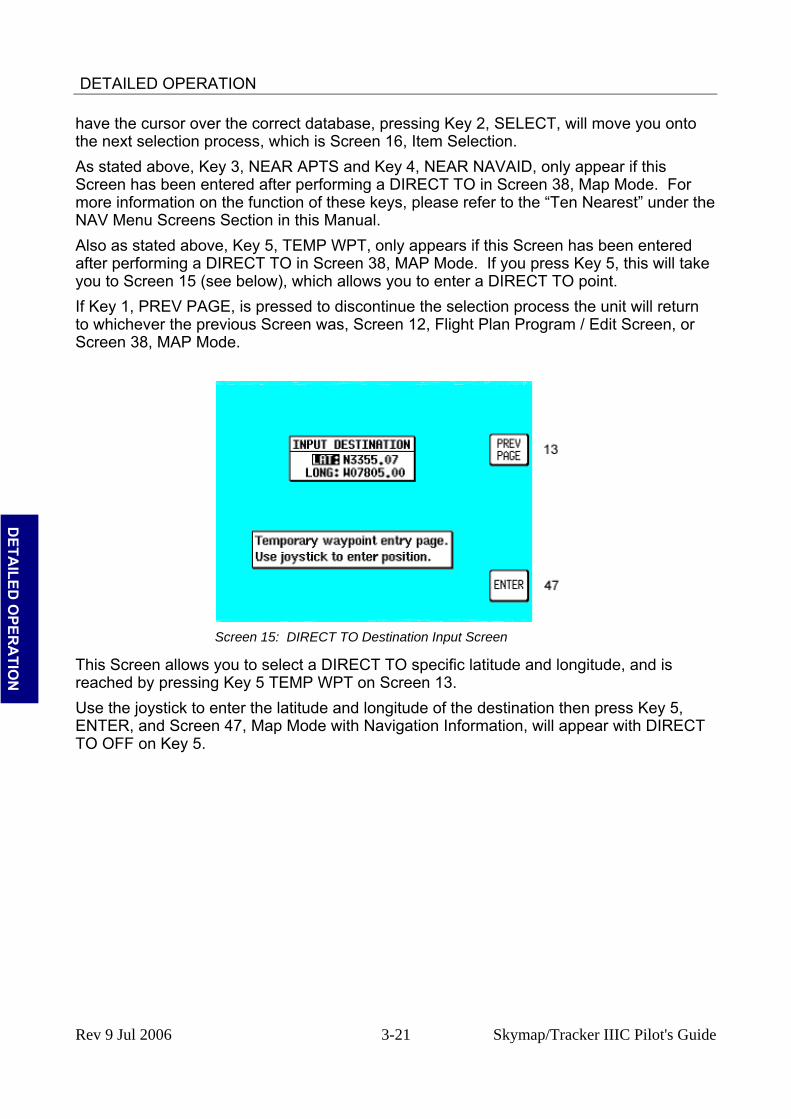
DETAILED OPERATION
have the cursor over the correct database, pressing Key 2, SELECT, will move you onto the next selection process, which is Screen 16, Item Selection. As stated above, Key 3, NEAR APTS and Key 4, NEAR NAVAID, only appear if this Screen has been entered after performing a DIRECT TO in Screen 38, Map Mode. For more information on the function of these keys, please refer to the “Ten Nearest” under the NAV Menu Screens Section in this Manual. Also as stated above, Key 5, TEMP WPT, only appears if this Screen has been entered after performing a DIRECT TO in Screen 38, MAP Mode. If you press Key 5, this will take you to Screen 15 (see below), which allows you to enter a DIRECT TO point. If Key 1, PREV PAGE, is pressed to discontinue the selection process the unit will return to whichever the previous Screen was, Screen 12, Flight Plan Program / Edit Screen, or Screen 38, MAP Mode.
D
ETAILED
OPER
ATIO
N
Screen 15: DIRECT TO Destination Input Screen
This Screen allows you to select a DIRECT TO specific latitude and longitude, and is reached by pressing Key 5 TEMP WPT on Screen 13. Use the joystick to enter the latitude and longitude of the destination then press Key 5, ENTER, and Screen 47, Map Mode with Navigation Information, will appear with DIRECT TO OFF on Key 5.
Rev 9 Jul 2006 3-21 Skymap/Tracker IIIC Pilot's Guide

DETAILED OPERATION
Step 2. Selecting item from chosen database
Screen 16: Item Selection Screen
On entry to this Screen you will find the cursor positioned over the first letter of the first item in the selected database. If AIRPORTS, VORs, NDBs, INTs or AIRWAYS was selected on Screen 13, the first item in the data entry box on screen 16 is AREA:. This is an area filter, which can be set to a specific ICAO country or area code. If set to EG for example, only items in British airspace will appear in the list. Similarly, if set to LF, only items in French airspace will be displayed. In the USA, the airspace is sub-divided into seven areas known as K1 – K7. The area filter can again be set to any of these areas (see APPENDIX C for a full list of country and area codes).
D
ETA
ILED
OPE
RA
TIO
N
If the area filter is set to ALL DATA, all the data from the selected database contained on the memory card for the entire area covered will appear in the list. If AIRPORTS was selected on Screen 13 the cursor will be positioned over the word ICAO:. Airports may be selected by ICAO code, airport name or associated city name and in addition, once an airport has been selected, a particular runway threshold at that airport can be selected. If you wish to select an airport by name or associated city name, use the joystick to move the cursor down to name then right to the first character. If you wish to select a specific runway threshold, move the cursor down to R/W then right to the word NONE. Moving the joystick up or down will now allow you to select a specific runway threshold (if threshold information is available for that airport in the Jeppesen database). When selecting names, use the joystick to scroll the initial letters through the alphabet. Once the required initial letter has been selected, move the joystick to the right and repeat the process. In this way you can scroll through all the items from the selected database, narrowing your search field. If you move the joystick to the left, the cursor will also move left one step, allowing you to make another selection. On this Screen, Key 5 labelled MORE INFO gives additional information about the selected item. When an airport is selected but no runway, the entry into your flight plan will be the name displayed followed by the airport's ICAO code. When a runway is selected, the entry into your flight plan will be the airport's ICAO code followed by the runway ident. For example, if you select runway 32L at Goodwood, the entry to your flight plan would be EGHR 32L.
Rev 9 Jul 2006 3-22 Skymap/Tracker IIIC Pilot's Guide

DETAILED OPERATION
Once you have reached the desired item, pressing Key 1, ENTER, will select it and either return you to Screen 12, Flight Plan Program / Edit Screen, entering the item to your flight plan or invoke the DIRECT TO and take you to Screen 47, MAP Mode with NAV Information, depending on which entry flight plan to Screen 13 you happen to have used.
Once you have reached the desired item, pressing Key 1, ENTER, will select it and either return you to Screen 12, Flight Plan Program / Edit Screen, entering the item to your flight plan or invoke the DIRECT TO and take you to Screen 47, MAP Mode with NAV Information, depending on which entry flight plan to Screen 13 you happen to have used. If VOR’s, NDB’s or intersections / approach waypoints were selected on Screen 13, Database Selection Screen, you will see a two-letter ICAO area code displayed to the right of the identifier. If you have the area filter set to ALL, you can move the cursor over to the two-letter ICAO code and select items with similar names in other areas. For example, there are four NDB’s in the Europe area with the indent ‘AB’. To select any one of these, first select AB then move the cursor to the right so that it is positioned over the two-letter ICAO code. By moving the joystick up and down is it now possible to select EK, ES, LF or LO as a country code. By doing this you can select the ‘AB’ NDB in Finland (EK), Sweden (ES), France (LF) and Austria (LO).
If VOR’s, NDB’s or intersections / approach waypoints were selected on Screen 13, Database Selection Screen, you will see a two-letter ICAO area code displayed to the right of the identifier. If you have the area filter set to ALL, you can move the cursor over to the two-letter ICAO code and select items with similar names in other areas. For example, there are four NDB’s in the Europe area with the indent ‘AB’. To select any one of these, first select AB then move the cursor to the right so that it is positioned over the two-letter ICAO code. By moving the joystick up and down is it now possible to select EK, ES, LF or LO as a country code. By doing this you can select the ‘AB’ NDB in Finland (EK), Sweden (ES), France (LF) and Austria (LO).
When selecting a beacon, intersection or approach waypoint, check the ICAO area code carefully since there are many duplicates present in the database.
Checking the area code will eliminate any ambiguity.
Graphical Viewing and Editing of Flight Plans
Screen 19: View and Edit Flight Plans On Map Screen
DETA
ILED O
PERA
TION
ILED
OPER
ATIO
N
This Screen is accessed by pressing FLIGHT PLAN in Main Menu, followed by EDIT FPLN and Key 5, View Map, on Screen 11, Flight Plan Selection Screen. Screen 19 is displayed showing the starting point of the selected flight plan centred in the middle of the display. The legs and waypoints are shown as in the illustration above. The joystick can be used to move the pointer. The screen window can be moved around the map by “bumping” the screen borders left, right, up or down with the pointer. Distance and bearing boxes below the map show distance and bearing from the last waypoint in the flight plan to the pointer. This feature allows you to enter waypoints as a distance and bearing from the previous flight plan point. To build a flight plan you simply point at the first item to be included in the flight plan and press Key 2, ADD WPT (or ADD WayPoinT). This will place an S (for Start) next to the waypoint. If no suitable data point or user waypoint is available beneath the pointer, a new user waypoint will be created; which can be given a name later by using Screen 9, Manual
Rev 9 Jul 2006 3-23 Skymap/Tracker IIIC Pilot's Guide

DETAILED OPERATION
User Waypoint Edit Screen. Now move the pointer to the second item in the flight plan and press Key 2, ADD WPT. This will place an E (for End) next to the waypoint. To systematically create additional legs, draw a line from the waypoint marked (E), with the pointer, to the next waypoint and press ADD WPT again. You will notice that the last point in the flight plan will always be labelled (E). Once you have finished building the flight plan press PREV PAGE, this will detach the pointer from the flight plan. Press PREV PAGE again to return to screen entered from, saving any changes made. If you wish to add a new waypoint to a flight plan which you have stopped building (which is also the case if you are editing an existing flight plan), whether it is at the start, the end or the middle of the flight plan, you will need to highlight the appropriate point (i.e.: either the start waypoint (S), the end waypoint (E) or the leg line in which you wish to add a new waypoint). As soon as you do this, the ADD WPT or GRAB LINE key will appear. Press the ADD WPT or GRAB LINE key to join the pointer back to the flight plan line and then move it to the new waypoint (NOTE: key 2 reverts to ADD WPT at this point). Once over the new waypoint press ADD WPT to insert it, otherwise press PREV PAGE to cancel this action. Pressing Key 1 PREV PAGE again, returns to the screen entered from, saving any changes made. If, for example you wanted to add DEAL into the existing flight plan going from MANSTON to DOVER VOR shown in the illustration above, you would first position the pointer over the track line between Manston and Dover VOR, thereby highlighting it and then press Key 2, GRAB LINE. This will pick up the line. You would then move the pointer, stretching the track line like a rubber band, until it was over DEAL and press Key 2, ADD WPT. The new track line would then be set joining MANSTON to DEAL to DOVER VOR and the numbers shown next to DOVER VOR and all subsequent waypoints would be increased by one. DEAL would become 01, DOVER VOR 02 etc.
D
ETA
ILED
OPE
RA
TIO
N
If, for example you wanted to add HERNE BAY to the end of the flight plan illustrated above, simply move the pointer over MANSTON, thereby highlighting it and then press Key 2, ADD WPT. This will draw a line from Manston to the pointer. Next move the pointer until it is over HERNE BAY, highlight it and press Key 2, ADD WPT again. To delete a waypoint from a flight plan, point at the item you wish to remove and press Key 5, DELETE WPT. To delete a newly created user waypoint, you have to return to Screen 9, Manual User Waypoint Edit Screen, or 10, View and Edit User Waypoints on the Map Screen. You can create user waypoints on Screen 19 but not delete them from there.
Rev 9 Jul 2006 3-24 Skymap/Tracker IIIC Pilot's Guide
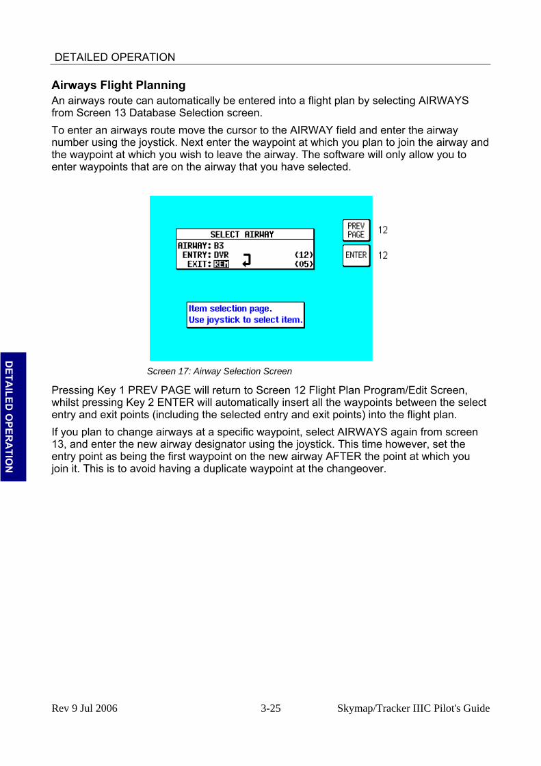
DETAILED OPERATION
Airways Flight Planning An airways route can automatically be entered into a flight plan by selecting AIRWAYS from Screen 13 Database Selection screen. To enter an airways route move the cursor to the AIRWAY field and enter the airway number using the joystick. Next enter the waypoint at which you plan to join the airway and the waypoint at which you wish to leave the airway. The software will only allow you to enter waypoints that are on the airway that you have selected.
D
ETAILED
OPER
ATIO
N
Screen 17: Airway Selection Screen
Pressing Key 1 PREV PAGE will return to Screen 12 Flight Plan Program/Edit Screen, whilst pressing Key 2 ENTER will automatically insert all the waypoints between the select entry and exit points (including the selected entry and exit points) into the flight plan. If you plan to change airways at a specific waypoint, select AIRWAYS again from screen 13, and enter the new airway designator using the joystick. This time however, set the entry point as being the first waypoint on the new airway AFTER the point at which you join it. This is to avoid having a duplicate waypoint at the changeover.
Rev 9 Jul 2006 3-25 Skymap/Tracker IIIC Pilot's Guide

DETAILED OPERATION
MAP MODE SCREENS
Screen 38: Basic Map Mode Screen
Pressing MAP in Main Menu will access this Screen. When you enter this Screen, if the Skymap IIIC's internal GPS receiver has been able to establish a fix or if the external GPS you are using to feed your Tracker IIIC is sending valid data, a Screen similar to the above will be displayed. The map is initially displayed at the Zoom Level where the Scale Bar represents 8nm. This is approximately the same scale as a 1:500,000 chart. If there is no valid GPS fix data available, the words NO FIX POSSIBLE will be shown across the centre of the screen in a box. If the fix is lost at any time during normal operation of the unit, the same NO FIX POSSIBLE box will be overlaid on the map. For an External GPS source the additional messages NO EXTERNAL POSITION DATA and INVALID EXTERNAL POSITION DATA may be displayed in place of NO FIX POSSIBLE.
D
ETA
ILED
OPE
RA
TIO
N
The map will be shown in either North Up mode or Track Up mode depending upon the setting you have made from Screen 22, Map Customisation Screen. The displayed data will be updated every second. From this page, if you press Key 1, Screen 2 Main Menu will take its place. You can use Keys 2 and 3 at any time to zoom the map in and out to whichever one of the twelve pre-set scales you wish to use. The levels of detail appearing at each zoom level can be selected on Screen 22A/B or C, described in the Setup Screens Section of this Manual. If you want to zoom in or out by more than one step at a time, you can apply multiple presses to Keys 2, ZOOM IN, and 3, ZOOM OUT, whilst watching the scale bar calibration figure and the ZOOMING message box. The small boxes marked TRK: and GS: display your present track and ground speed. Ground speed is displayed in the units selected on Screen 22, Map Customisation Screen. Track will be magnetic (i.e.: true with local variation automatically taken into account). The box marked POS: will display your present position as a distance and cardinal bearing from the nearest item in the database. The geographical item used to describe your position to you is chosen on the basis of the POSITION REF: setting on Screen 22, Map Customisation Screen. If you have chosen VOR’s as the position reference on Screen 22, your position will be reported as a distance (range) and bearing from the nearest VOR. If you have chosen VOR’s & AIRPORTS as the position reference on Screen 22 and your position is within 5nm of an airport, your position will be reported as a distance and bearing from that airport
Rev 9 Jul 2006 3-26 Skymap/Tracker IIIC Pilot's Guide
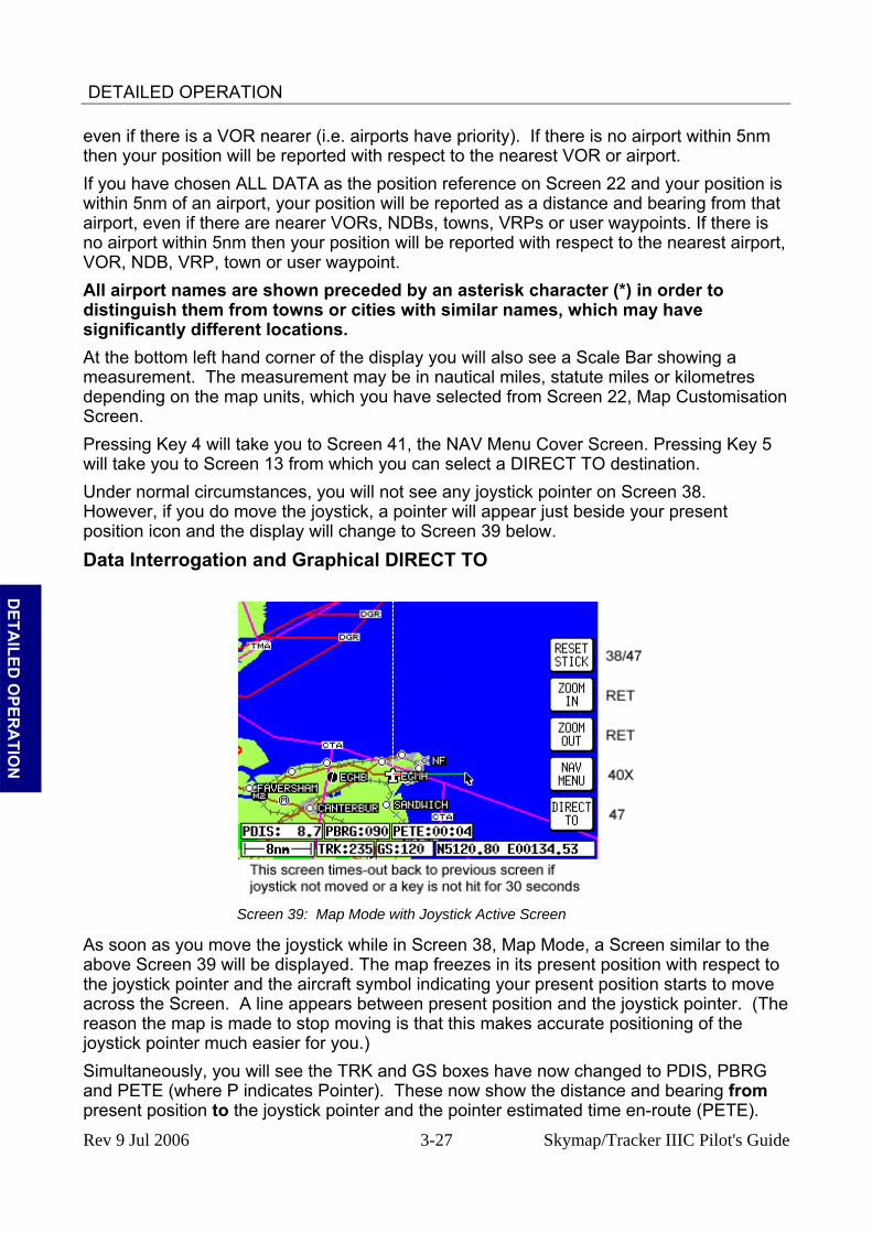
DETAILED OPERATION
even if there is a VOR nearer (i.e. airports have priority). If there is no airport within 5nm then your position will be reported with respect to the nearest VOR or airport. If you have chosen ALL DATA as the position reference on Screen 22 and your position is within 5nm of an airport, your position will be reported as a distance and bearing from that airport, even if there are nearer VORs, NDBs, towns, VRPs or user waypoints. If there is no airport within 5nm then your position will be reported with respect to the nearest airport, VOR, NDB, VRP, town or user waypoint. All airport names are shown preceded by an asterisk character (*) in order to distinguish them from towns or cities with similar names, which may have significantly different locations. At the bottom left hand corner of the display you will also see a Scale Bar showing a measurement. The measurement may be in nautical miles, statute miles or kilometres depending on the map units, which you have selected from Screen 22, Map Customisation Screen. Pressing Key 4 will take you to Screen 41, the NAV Menu Cover Screen. Pressing Key 5 will take you to Screen 13 from which you can select a DIRECT TO destination. Under normal circumstances, you will not see any joystick pointer on Screen 38. However, if you do move the joystick, a pointer will appear just beside your present position icon and the display will change to Screen 39 below.
Data Interrogation and Graphical DIRECT TO
Screen 39: Map Mode with Joystick Active Screen
D
ETAILED
OPER
ATIO
N
As soon as you move the joystick while in Screen 38, Map Mode, a Screen similar to the above Screen 39 will be displayed. The map freezes in its present position with respect to the joystick pointer and the aircraft symbol indicating your present position starts to move across the Screen. A line appears between present position and the joystick pointer. (The reason the map is made to stop moving is that this makes accurate positioning of the joystick pointer much easier for you.) Simultaneously, you will see the TRK and GS boxes have now changed to PDIS, PBRG and PETE (where P indicates Pointer). These now show the distance and bearing from present position to the joystick pointer and the pointer estimated time en-route (PETE).
Rev 9 Jul 2006 3-27 Skymap/Tracker IIIC Pilot's Guide
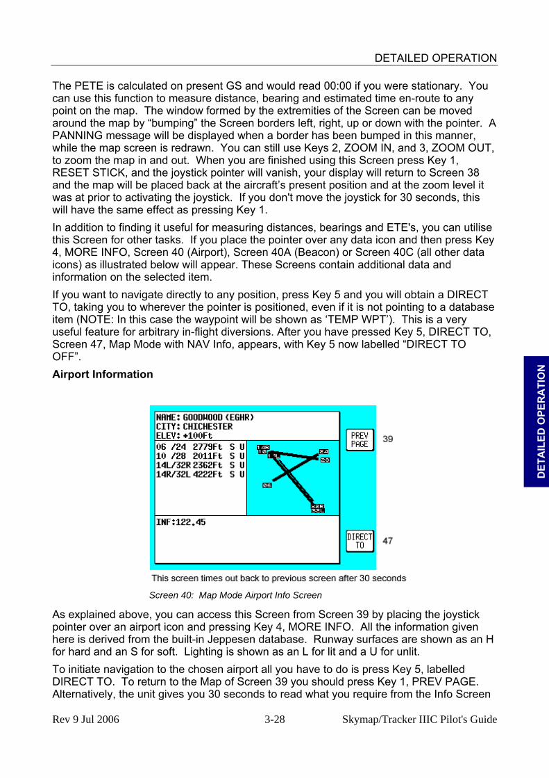
DETAILED OPERATION
The PETE is calculated on present GS and would read 00:00 if you were stationary. You can use this function to measure distance, bearing and estimated time en-route to any point on the map. The window formed by the extremities of the Screen can be moved around the map by “bumping” the Screen borders left, right, up or down with the pointer. A PANNING message will be displayed when a border has been bumped in this manner, while the map screen is redrawn. You can still use Keys 2, ZOOM IN, and 3, ZOOM OUT, to zoom the map in and out. When you are finished using this Screen press Key 1, RESET STICK, and the joystick pointer will vanish, your display will return to Screen 38 and the map will be placed back at the aircraft’s present position and at the zoom level it was at prior to activating the joystick. If you don't move the joystick for 30 seconds, this will have the same effect as pressing Key 1. In addition to finding it useful for measuring distances, bearings and ETE's, you can utilise this Screen for other tasks. If you place the pointer over any data icon and then press Key 4, MORE INFO, Screen 40 (Airport), Screen 40A (Beacon) or Screen 40C (all other data icons) as illustrated below will appear. These Screens contain additional data and information on the selected item. If you want to navigate directly to any position, press Key 5 and you will obtain a DIRECT TO, taking you to wherever the pointer is positioned, even if it is not pointing to a database item (NOTE: In this case the waypoint will be shown as ‘TEMP WPT’). This is a very useful feature for arbitrary in-flight diversions. After you have pressed Key 5, DIRECT TO, Screen 47, Map Mode with NAV Info, appears, with Key 5 now labelled “DIRECT TO OFF”.
D
ETA
ILED
OPE
RA
TIO
N
Airport Information
Screen 40: Map Mode Airport Info Screen
As explained above, you can access this Screen from Screen 39 by placing the joystick pointer over an airport icon and pressing Key 4, MORE INFO. All the information given here is derived from the built-in Jeppesen database. Runway surfaces are shown as an H for hard and an S for soft. Lighting is shown as an L for lit and a U for unlit. To initiate navigation to the chosen airport all you have to do is press Key 5, labelled DIRECT TO. To return to the Map of Screen 39 you should press Key 1, PREV PAGE. Alternatively, the unit gives you 30 seconds to read what you require from the Info Screen
Rev 9 Jul 2006 3-28 Skymap/Tracker IIIC Pilot's Guide

DETAILED OPERATION
and then automatically returns to Screen 39. Pressing Key 5, DIRECT TO, in MAP Mode when the joystick is not active, calls up the Select Database Screen; from here you can select an airport of interest from the airports database as if you were selecting it for a DIRECT TO. Beacon Information
Screen 40A: Map Mode Beacon Information Screen
D
ETAILED
OPER
ATIO
N
As explained above, you can access this Screen from Screen 39 by placing the joystick pointer over a VOR or NDB icon and pressing Key 4, MORE INFO. Full details of the Beacon are listed, type, frequency and ident. The fourth line in the box is a visual representation of the Morse ident and if you are one of those pilots whose knowledge of Morse is less than perfect, all you have to do is press Key 2, IDENT. The unit will then sound the correct ident (on its internal bleeper and on the external alarm, if this is switched on). You can then compare this to the ident you are hearing over the radio to verify that you are indeed tuned to the beacon you want. To initiate a goto for the chosen Beacon (VOR or NDB) all you have to do is press Key 5, labelled DIRECT TO. To return to the Map of Screen 39 you should press Key 1, PREV PAGE. Alternatively, the unit gives you 30 seconds to read what you require and then automatically returns to Screen 39. Pressing Key 5, DIRECT TO, in Map Mode when the joystick is not active, can also access this Screen. Allowing you to call up the item of interest from the either the VOR’s or NDB’s database as if you were selecting it for a DIRECT TO, although if the screen is accessed in this manner the map is not displayed.
Rev 9 Jul 2006 3-29 Skymap/Tracker IIIC Pilot's Guide

DETAILED OPERATION
General Icon Information
Screen 40C: Map Mode General Information Screen
As explained above, you can access this Screen from Screen 39 by placing the joystick pointer over any data icon that is not an airport, VOR or NDB and pressing Key 4, MORE INFO. All available information concerning the chosen data item is then listed. To initiate a goto for the chosen item all you have to do is press Key 5, labelled DIRECT TO. To return to the Map of Screen 39 you should press Key 1, PREV PAGE. Alternatively, the unit gives you 30 seconds to read what you require and then automatically returns to Screen 39.
D
ETA
ILED
OPE
RA
TIO
N
Airspace Interrogation In order to interrogate a piece of airspace in MAP Mode, move the joystick operated pointer and point at one of the airspace boundaries. After you have released the joystick, the software will search the airspace database and after a short time will re-draw the piece of airspace to which you have pointed in a bolder line. IMPORTANT: When a single airspace boundary line is shared by two different pieces of airspace (which is very common), the airspace with the lower vertical limit will always be highlighted. Once you are sure the piece of airspace highlighted is the piece you want information on (you may have to zoom out to verify this, but beware, some airspace switches off as you zoom out dependant on the settings made in Screen 22C, Airspace Data Class Setup Screen), press MORE INFO key and Screen 40B, Airspace Information Screen, will be displayed.
Rev 9 Jul 2006 3-30 Skymap/Tracker IIIC Pilot's Guide
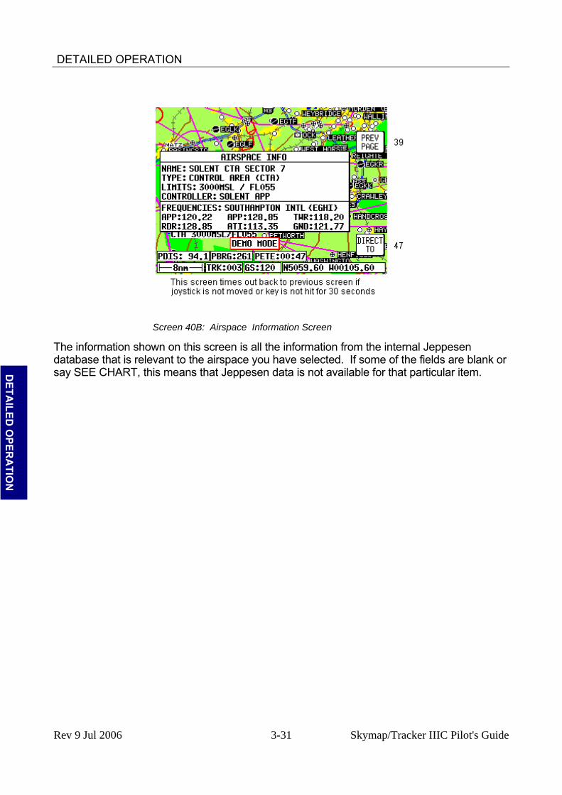
DETAILED OPERATION
Screen 40B: Airspace Information Screen
The information shown on this screen is all the information from the internal Jeppesen database that is relevant to the airspace you have selected. If some of the fields are blank or say SEE CHART, this means that Jeppesen data is not available for that particular item.
D
ETAILED
OPER
ATIO
N
Rev 9 Jul 2006 3-31 Skymap/Tracker IIIC Pilot's Guide

DETAILED OPERATION
NAV MENU SCREENS
Screen 41: NAV Menu Cover Screen
You can enter this important Screen by pressing Key 4, NAV MENU, while in MAP Mode (on Screen 38 or 47). It is a versatile Screen with several useful functions. If you move the joystick up or down when in this Screen, the screen layout presented when in Map Mode with NAV Information (or NAV Mode i.e. flying a flight plan or a DIRECT TO) can be selected to be one of the following
D
ETA
ILED
OPE
RA
TIO
N
TOPO ON: Large map, full colour cartography, and small NAV information text. TOPO ON, LRG TXT: Large map, full colour cartography, and large NAV information text. This will revert to the TOPO ON large map when the joystick is hit. TOPO ON, CDI: Pseudo CDI style display, which reverts to TOPO ON large map when joystick is hit. The TOPO ON map is also displayed if no flight plan or DIRECT TO is active. TOPO OFF: Large map, black background, no cartography, and Jeppesen data only, small NAV information text. TOPO OFF, LRG TXT: Large map, black background, no cartography, and Jeppesen data only, large NAV information text. This will revert to the TOPO OFF large map when the joystick is hit. TOPO OFF, CDI: Pseudo CDI style display, which reverts to TOPO OFF large map when joystick is hit. The TOPO OFF map is also displayed if no flight plan or DIRECT TO is active. Please refer to the Map Setup Screens in the Setup Screens Section of this Manual for further information regarding data settings for each mode. If you wish to return to your previous Map Mode Screen at any time, press Key 1, MAP. Key 2, FLIGHT PLAN, gives you direct access to Flight Planning Mode where you can manually select, cancel and edit flight plans as required. If you press Key 3, NEAR APTS, you will be presented with Screen 43, Ten Nearest Airports Screen, on which you can read off the ten airports nearest to your present
Rev 9 Jul 2006 3-32 Skymap/Tracker IIIC Pilot's Guide
DETAILED OPERATION
position. If you press Key 4, NEAR NAVAID, you will see Screen 45, Ten Nearest Beacons Screen, giving you details of the ten VOR’s and NDB’s nearest to you. For more information on Screens 43 and 45 refer to the Ten Nearest later on in this Section of the Manual. When a DIRECT TO is active, Key 4 will read CENTER CDI which centres the Course Deviation Indicator in the bottom right hand corner of the display. The NEAR NAVAID function will still be available via the NEAR APTS function. If you wish to save your present position, press Key 5, SAVE WPT, and your co-ordinates will be saved as the next available user waypoint number. Once the user waypoint has been saved, the Screen will revert to Map Mode (Screen 38 or 47) where the new user waypoint will already feature on the map. The text boxes in the bottom half of the screen gives the following information: NAV Mode selected (one of six options described above) Position in plain English Position in latitude/longitude (or the co-ordinate system selected on the Map Setup Screen) Track and Ground Speed GPS Altitude MSA for the present position
D
ETAILED
OPER
ATIO
N
The MSA box displays the highest Grid MORA value within a ten mile radius of your present position at all times. See APPENDIX C for a more detailed explanation of Grid MORA.
WARNING: The MSA altitudes displayed are advisory in nature only. They should not be relied upon as the sole source of obstacle and terrain
avoidance information. Always refer to current aeronautical charts for appropriate minimum clearance altitudes.
Rev 9 Jul 2006 3-33 Skymap/Tracker IIIC Pilot's Guide

DETAILED OPERATION
Selecting a Flight Plan
Screen 42: Flight Plan Selection Screen
Pressing Key 2, FLIGHT PLAN, on Screen 41, NAV Menu Cover Screen, enters this Screen. On entry to this Screen you will see a cursor positioned over Flight Plan Number 01, or if there is a flight plan already active, its number will be shown instead of the Flight plan last touched. You will see the first few items of the selected flight plan together with its final destination in the box under the Flight Plan Number. You can select any flight plan you want by using the joystick to scroll the flight plan number up or down. You are free to select any one of the 99 available flight plans. If you wish to return to the NAV Menu Cover Screen (Screen 41) press the PREV PAGE Key 1.
D
ETA
ILED
OPE
RA
TIO
N
If the selected flight plan is already running, Key 5 will read FPLN OFF. If there is no active flight plan, Key 5 will be blank and Key 2 will read SELECT. Pressing Key 2 will call Screen 12, Flight Plan Program/Edit Screen for the selected flight plan. An active flight plan can be switched off at any time by pressing Key 5, FPLN OFF. Pressing Key 5 will cancel the active flight plan and allow you to gain access to what was the active flight plan. (In the interests of safety, the software has been designed not to permit you to edit and fly a flight plan at the same time.) Pressing Key 4 gives a shortcut to Screen 60, the E6-B Trip/Fuel Planning Screen (see Trip/Fuel Planning in the E6B Calculator Section of this Manual for more detail). Whenever Screen 60 is displayed the flight plan selected on Screen 42 will automatically be shown.
Rev 9 Jul 2006 3-34 Skymap/Tracker IIIC Pilot's Guide
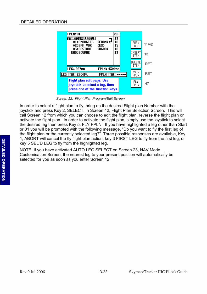
DETAILED OPERATION
Screen 12: Flight Plan Program/Edit Screen
In order to select a flight plan to fly, bring up the desired Flight plan Number with the joystick and press Key 2, SELECT, in Screen 42, Flight Plan Selection Screen. This will call Screen 12 from which you can choose to edit the flight plan, reverse the flight plan or activate the flight plan. In order to activate the flight plan, simply use the joystick to select the desired leg then press Key 5, FLY FPLN. If you have highlighted a leg other than Start or 01 you will be prompted with the following message, “Do you want to fly the first leg of the flight plan or the currently selected leg?” Three possible responses are available, Key 1, ABORT will cancel the fly flight plan action, key 3 FIRST LEG to fly from the first leg, or key 5 SEL’D LEG to fly from the highlighted leg.
D
ETAILED
OPER
ATIO
N
NOTE: If you have activated AUTO LEG SELECT on Screen 23, NAV Mode Customisation Screen, the nearest leg to your present position will automatically be selected for you as soon as you enter Screen 12.
Rev 9 Jul 2006 3-35 Skymap/Tracker IIIC Pilot's Guide
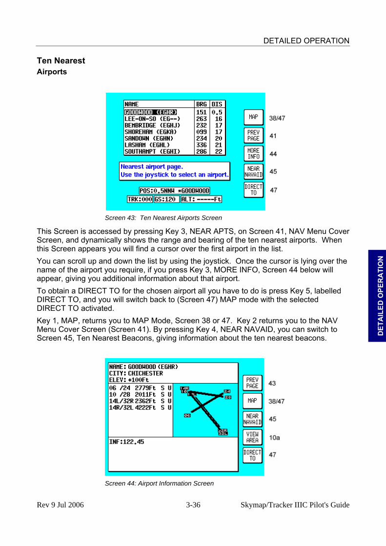
DETAILED OPERATION
Ten Nearest Airports
Screen 43: Ten Nearest Airports Screen
This Screen is accessed by pressing Key 3, NEAR APTS, on Screen 41, NAV Menu Cover Screen, and dynamically shows the range and bearing of the ten nearest airports. When this Screen appears you will find a cursor over the first airport in the list.
D
ETA
ILED
OPE
RA
TIO
N
You can scroll up and down the list by using the joystick. Once the cursor is lying over the name of the airport you require, if you press Key 3, MORE INFO, Screen 44 below will appear, giving you additional information about that airport. To obtain a DIRECT TO for the chosen airport all you have to do is press Key 5, labelled DIRECT TO, and you will switch back to (Screen 47) MAP mode with the selected DIRECT TO activated. Key 1, MAP, returns you to MAP Mode, Screen 38 or 47. Key 2 returns you to the NAV Menu Cover Screen (Screen 41). By pressing Key 4, NEAR NAVAID, you can switch to Screen 45, Ten Nearest Beacons, giving information about the ten nearest beacons.
Screen 44: Airport Information Screen
Rev 9 Jul 2006 3-36 Skymap/Tracker IIIC Pilot's Guide

DETAILED OPERATION
Once you have selected an airport on Screen 43 and pressed Key 3, MORE INFO, the display will change to Screen 44 above. This gives additional information about runways, frequencies, elevation etc. for the airport in question. To return from this Screen to Map Mode (Screen 38 or 47) you simply press Key 2. To select another airport from the Ten Nearest (Screen 43) you press Key 1 and if you want to see the list of ten nearest beacons, simply press Key 3, which will take you directly to Screen 45, Ten Nearest Beacons. To obtain a DIRECT TO for the chosen airport all you have to do is press Key 5, labelled DIRECT TO, and you will switch back to (Screen 47) MAP Mode with the selected DIRECT TO activated. If you want to view the area immediately around the chosen airport, press Key 4. This will call Screen 10A which is very similar to Screen 10, the View and Edit User Waypoint on the Map Screen. Screen 10A can be cancelled by pressing Key 1, PREV PAGE. Beacons
D
ETAILED
OPER
ATIO
N
Screen 45: Ten Nearest Beacons Screen
This Screen is accessed by pressing Key 4, NEAR NAVAID, on Screen 41, NAV Menu Cover Screen, and dynamically shows the range and bearing of the ten nearest beacons. When this Screen appears you will find a cursor placed over the first beacon in the list. The list can be scrolled up and down using the joystick. Once you have placed the cursor over the name of the beacon you want, press Key 3, MORE INFO, to display Screen 46 below, which gives additional information about that beacon. Pressing Key 1 will return you to MAP mode (Screen 38 or 47). Key 2 returns you to Screen 41, NAV Menu Cover Screen. Pressing Key 4, NEAR APTS, will take you to Screen 43, giving you the list of the ten nearest airports. To obtain a DIRECT TO for the chosen beacon all you have to do is press Key 5, labelled DIRECT TO, and you will switch back to (Screen 47) MAP mode with the selected DIRECT TO activated.
Rev 9 Jul 2006 3-37 Skymap/Tracker IIIC Pilot's Guide

DETAILED OPERATION
Screen 46: Beacon Information Screen
The Screen above shows the additional information about the beacon chosen on Screen 45, Ten Nearest Beacons. From here by pressing Key 2 you will get back to MAP mode (Screen 38 or 47). To select another beacon from the Ten Nearest (Screen 45) you press Key 1. If you press Key 3, IDENT, the unit will mimic the Morse code ident for the chosen beacon on the internal beeper (and on the external alarm if you switched this on in Screen 23, NAV Mode Customisation Screen).
D
ETA
ILED
OPE
RA
TIO
N
If you want to view the area immediately around the chosen beacon, press Key 4. This will call Screen 10A which is very similar to screen 10, the View and Edit User Waypoint on the Map Screen. Screen 10A can be cancelled by pressing Key 1, PREV PAGE. To obtain a DIRECT TO for the chosen beacon all you have to do is press Key 5, labelled DIRECT TO, and you will switch back to (Screen 47) MAP mode with the selected DIRECT TO activated.
Rev 9 Jul 2006 3-38 Skymap/Tracker IIIC Pilot's Guide

DETAILED OPERATION
MAP MODE WITH NAV INFORMATION Whenever a flight plan is active or you have called for a DIRECT TO, the map will have extra navigation information added to it and will resemble Screen 47 below. Alternatively you may have selected one of the other Navigation Modes detailed in the NAV Menu Screens Section of this Manual. The same navigation data is presented on all the alternative screens in different ways. The following text refers to the standard Navigation Mode Screen setting (TOPO ON). Alternative Screens 47A and 47B are discussed at the end of this section.
D
ETAILED
OPER
ATIO
N
Screen 47: Map Mode with NAV Information Screen
If the TOPO OFF Large Map Mode is selected, the map will display aeronautical data only on a black background. The Course Deviation Indicator (CDI) at the bottom right of the map can be switched ON or OFF or be set to work numerically and the Full Scale Deflection (FSD) selected on Screen 23, NAV Mode Customisation Screen. If you have selected the CDI alarm ON, when the last element of the CDI bar graph comes on (or when the full scale value as set on Screen 23 is reached) the internal and external alarms (if switched on) will beep at a rate of 2Hz for 5 seconds. Key 5 will change to ALARM OFF and if you press this before the 5 seconds are up this will silence the alarm. When the alarm switches off automatically after 5 seconds, Key 5's label will go blank and have no function for 2 seconds then revert to DIRECT TO (or DIRECT TO OFF). This is to make sure you don't inadvertently select or cancel DIRECT TO mode if you press this Key just as the alarm is cancelling automatically. The CDI alarm resets itself as soon as you come back within the full scale set. It will then be reactivated whenever the full scale is reached again. The box at the bottom left of the map window shows the destination point when you are in DIRECT TO Mode preceded by the “DIRECT TO” symbol or the FROM and TO waypoints when you are in Flight Plan Mode. A great deal of other navigation information is available to you above and below the map. (The positioning of this data that is described in the following relates to when the screen is in Landscape Mode. The position of some of the items is different when Portrait Mode is used.) Starting at the top of the screen on the left hand side you will see DIS. This is the distance or range to run to the destination point from your present position. This distance
Rev 9 Jul 2006 3-39 Skymap/Tracker IIIC Pilot's Guide
DETAILED OPERATION
figure is given in whichever units you selected on Screen 22, Map Customisation Screen. In the left centre of the screen at the top you can read BRG. This is the magnetic bearing to the next turning point. To the right of BRG at the top of the map is the ETE. This gives the Estimated Time En-route (i.e. the estimated time, in hours and minutes, that it will take you to get to the destination point from your present position assuming you maintain your present ground speed. On the Skymap IIIC unit only, at the top right of the map is the ETA. This is the Estimated Time of Arrival at the next turning point. Ensure you have set the local time offset correctly to get local ETA’s. Refer to the GPS Status Screens Section of this Manual for more details. (The reason that ETA is not available on Tracker IIIC is that, depending on the type of GPS receiver in use, real time and local time offset is not always known.) In the left centre of the screen at the bottom is TRK. This is the actual magnetic track the aircraft is travelling over the ground. By comparing this with your magnetic heading you can make an estimate of the crosswind component. To the right of TRK is GS. This is the actual ground speed of the aircraft and is displayed in Knots if you set the map units to nautical miles on Screen 22, Map Customisation Screen, MPH if you set them to statute miles or KPH if the map units are set to kilometres. By comparing the GS with your TAS you can make an estimate of the head or tail wind component. Alternatively refer to Screen 58, Density Altitude, True Air Speed, and Winds Aloft in the E6B Calculator Screens section of this manual.
D
ETA
ILED
OPE
RA
TIO
N
If ground speed is less than 3 Kt., the map will revert to North Up even if Track Up is selected. This is to stop the map rotating when static due to the small position fix changes caused by atmospheric and other effects. If you have entered this Screen 47 by activating a flight plan, a DIRECT TO can be performed on top of the flight plan. You can initiate the DIRECT TO either to an item from the database or by using the joystick pointer or by calling up one of the 10 nearest airports or beacons. In each case the Key 5 label will change to “DIRECT TO OFF”. The flight plan that previously was active will fall into the background and will be replaced by the DIRECT TO information. When the DIRECT TO destination is reached or whenever you press the DIRECT TO OFF Key (Key 5), the flight plan and its information will be reinstated.
Viewing En-route ETA’s and Direct-To Page When flying a flight plan, the ETA’s for each leg of the flight plan can be viewed on Screen 41A which is accessed by pressing Key 5, DIRECT TO on the MAP mode screen (screen 47).
Rev 9 Jul 2006 3-40 Skymap/Tracker IIIC Pilot's Guide
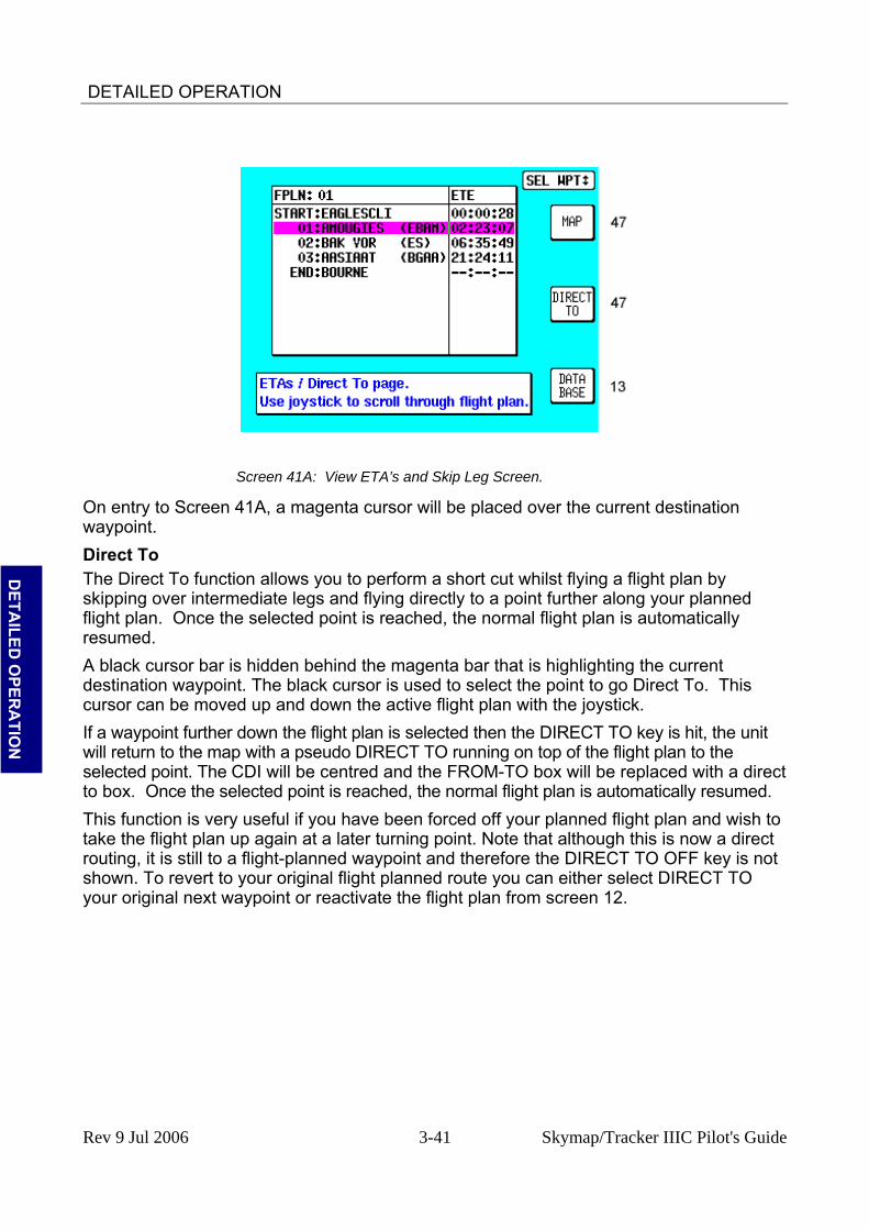
DETAILED OPERATION
Screen 41A: View ETA’s and Skip Leg Screen.
On entry to Screen 41A, a magenta cursor will be placed over the current destination waypoint. Direct To
D
ETAILED
OPER
ATIO
N
The Direct To function allows you to perform a short cut whilst flying a flight plan by skipping over intermediate legs and flying directly to a point further along your planned flight plan. Once the selected point is reached, the normal flight plan is automatically resumed. A black cursor bar is hidden behind the magenta bar that is highlighting the current destination waypoint. The black cursor is used to select the point to go Direct To. This cursor can be moved up and down the active flight plan with the joystick. If a waypoint further down the flight plan is selected then the DIRECT TO key is hit, the unit will return to the map with a pseudo DIRECT TO running on top of the flight plan to the selected point. The CDI will be centred and the FROM-TO box will be replaced with a direct to box. Once the selected point is reached, the normal flight plan is automatically resumed. This function is very useful if you have been forced off your planned flight plan and wish to take the flight plan up again at a later turning point. Note that although this is now a direct routing, it is still to a flight-planned waypoint and therefore the DIRECT TO OFF key is not shown. To revert to your original flight planned route you can either select DIRECT TO your original next waypoint or reactivate the flight plan from screen 12.
Rev 9 Jul 2006 3-41 Skymap/Tracker IIIC Pilot's Guide

DETAILED OPERATION
Arrival at an En-route User Waypoint
Screen 48: NAV Information and WPT ALERT Flags Showing – En-route Screen
To set the radius for the Arrival Alarm you should refer to the data on Screen 23, NAV Mode Customisation Screen. When the distance remaining to run to an en-route waypoint falls below the Arrival Alarm value, the [WPT ALERT] flag is displayed and the internal and external alarms (if switched on) beep at a rate of 2Hz for 5 seconds. To make the change to NEXT LEG you have to press Key 1 and if you wish to silence the alarm before the 5 seconds are up, simply press Key 5, the label of which has changed to ALARM OFF. The alarm is switched off automatically after 5 seconds; Key 5 will go blank and have no function for 2 seconds. It will then revert to DIRECT TO. This is a safety measure to prevent you from inadvertently selecting DIRECT TO mode by pressing Key 5 just as it is cancelling automatically.
D
ETA
ILED
OPE
RA
TIO
N
Once you have pressed Key 1 to select the next leg, Screen 47 re-appears showing all the relevant information for the new leg. The next leg of the flight plan will now be displayed as a solid magenta coloured line with a black border. This black border differentiates the track line from controlled airspace which has no border. If you pass the waypoint the flag will change to [WPT PASSED]. If the unit has been set up for AUTO NEXT LEG in Screen 23, then as the waypoint is passed the unit will automatically revert to Screen 47 with all the new leg information. Key 1 will go blank and inactive for two seconds. It will then revert to MAIN MENU. When the WPT Alert alarm has been given, a new box will appear at the bottom of the screen showing the new course [NEW CRS XXX] to steer for the next leg of the flight plan. The next leg of the flight plan will also be displayed as a solid white line. Prior to reaching a waypoint within a flight plan, Turn Anticipation provides navigation along a curved path segment to ensure a smooth transition between two adjacent legs in the flight plan. The curved path segment is based upon the aircraft's groundspeed and the amount of course angle change between the legs. Turn Anticipation will only work if it is selected ON in Screen 23, NAV Mode Customisation Screen, and if the course change is greater than 5° and less than 90°. If the course change is less than 5° then turn anticipation is not necessary. If the course change is greater than 90° it is up to the pilot which way round the turning point he turns.
Rev 9 Oct 2006 3-42 Skymap/Tracker IIIC Pilot's Guide
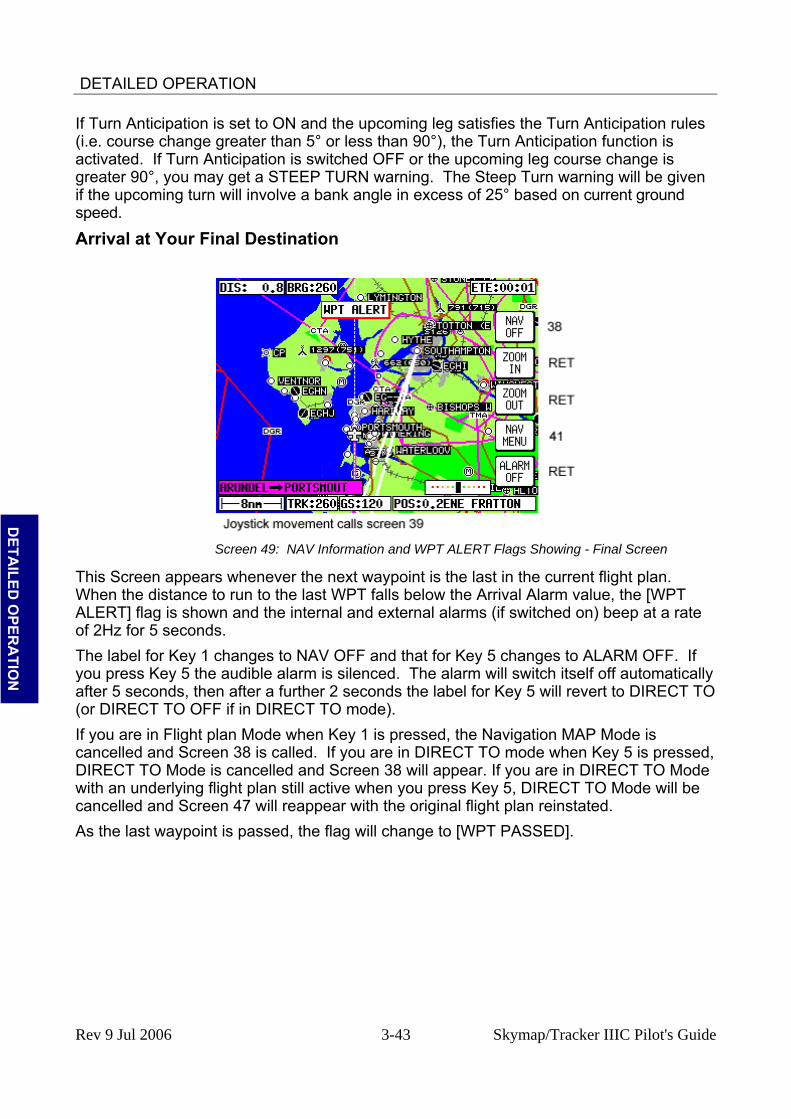
DETAILED OPERATION
If Turn Anticipation is set to ON and the upcoming leg satisfies the Turn Anticipation rules (i.e. course change greater than 5° or less than 90°), the Turn Anticipation function is activated. If Turn Anticipation is switched OFF or the upcoming leg course change is greater 90°, you may get a STEEP TURN warning. The Steep Turn warning will be given if the upcoming turn will involve a bank angle in excess of 25° based on current ground speed.
Arrival at Your Final Destination
Screen 49: NAV Information and WPT ALERT Flags Showing - Final Screen
D
ETAILED
OPER
ATIO
N
This Screen appears whenever the next waypoint is the last in the current flight plan. When the distance to run to the last WPT falls below the Arrival Alarm value, the [WPT ALERT] flag is shown and the internal and external alarms (if switched on) beep at a rate of 2Hz for 5 seconds. The label for Key 1 changes to NAV OFF and that for Key 5 changes to ALARM OFF. If you press Key 5 the audible alarm is silenced. The alarm will switch itself off automatically after 5 seconds, then after a further 2 seconds the label for Key 5 will revert to DIRECT TO (or DIRECT TO OFF if in DIRECT TO mode). If you are in Flight plan Mode when Key 1 is pressed, the Navigation MAP Mode is cancelled and Screen 38 is called. If you are in DIRECT TO mode when Key 5 is pressed, DIRECT TO Mode is cancelled and Screen 38 will appear. If you are in DIRECT TO Mode with an underlying flight plan still active when you press Key 5, DIRECT TO Mode will be cancelled and Screen 47 will reappear with the original flight plan reinstated. As the last waypoint is passed, the flag will change to [WPT PASSED].
Rev 9 Jul 2006 3-43 Skymap/Tracker IIIC Pilot's Guide

DETAILED OPERATION
Alternative Navigation Map Modes You may have selected one of the other Map presentation modes detailed in the NAV Menu Screens Section of this Manual. The same navigation data as described previously is presented on all the alternative screens in different ways. TOPO ON / TOPO OFF Large Text Mode
Screen 47A: TOPO ON Large Text NAV Information Screen.
D
ETA
ILED
OPE
RA
TIO
N
This Screen presents the numeric navigation information in large text laid over the map display in such a way as to allow you a forward view of the map if being used in Track Up Mode. As with standard Map NAV Mode, the CDI scale and format may be adjusted. If the joystick is touched, the display will immediately revert to Map format to allow full use of map graphics. When the joystick is reset or after 30 seconds with no key or joystick activity, Screen 47A will be reinstated. As with standard Map Mode, if the TOPO OFF Large Text Mode is selected, the map will display aeronautical data only on a black background. TOPO ON / TOPO OFF CDI (Pseudo CDI) Mode:
Rev 9 Jul 2006 3-44 Skymap/Tracker IIIC Pilot's Guide

DETAILED OPERATION
Screen 47B: CDI NAV Information Screen
This Screen presents numeric navigation information in small text but instead of a map display, shows a pseudo CDI complete with OBS knob. The aircraft icon in the center of the CDI will remain static and the outer ring represents the desired magnetic track between the start waypoint and the destination waypoint (i.e. magnetic bearing to waypoint if you were on track). On entering NAV Mode or activating a new flight plan leg or a DIRECT TO, the outer ring will show the desired track to the active waypoint. A GPS TRACK bug, which rotates with the aircraft’s actual track, is positioned on the CDI outer ring. This indicates the actual magnetic track of the aircraft. There is also included a conventional TO / FROM flag.
D
ETAILED
OPER
ATIO
N
Flying with the pseudo CDI is very similar to flying with a conventional VOR indicator. Off track error (XTE) is represented by a bar that moves left or right of center. The center of the scale represents the aircraft's position. As with a conventional CDI or VOR indicator, to correct your track error, fly towards the bar. The full scale deflection or scale of the CDI can be selected on Screen 23, NAV Mode Customization Screen. In order to gain, and remain on the desired track, adjust your aircraft heading until the CDI bar is centered. Once the CDI bar is in the center of the display indicating no cross track error (XTE), adjust your aircraft heading in small increments until the track bug, which rotates around the outer ring, is at the top of the display. Once the CDI is centered and the track bug is aligned at the top of the display you are flying precisely along your desired track. If the track bug is aligned at the top of the display but the CDI bar is not centered, this indicates you are flying parallel to your desired track by however far the XTE is indicating. If whilst flying a flight plan you need skip to another waypoint in the flight plan, press key 5 (DIRECT TO) followed by key 3 (DIRECT TO) in exactly the same way as described earlier in this section. The TO / FROM flag will normally point up to indicate you are flying TO the waypoint. When you pass your destination waypoint, the TO / FROM flag will point down to indicate you have passed the waypoint and you are now flying away FROM your destination. As you pass your waypoint and the FROM flag appears, the desired track ring will remain fixed at the original desired track and the CDI will continue to show track error left or right of the extended leg line.
Rev 9 Jul 2006 3-45 Skymap/Tracker IIIC Pilot's Guide
DETAILED OPERATION
If whilst en-route to a destination you decide that you would like to approach that destination point from an angle other than that displayed on the CDI by the desired track ring, you can alter the desired track setting by pushing the INC OBS (increment OBS) or DEC OBS (decrement OBS) Keys. This has the effect of rotating your desired track ring and hence rotating the desired track line on the map screen using the destination point as a pivot. For example if you were approaching an airport from the south west on an inbound heading of 070° but the runway in use at that airport was 09, it may be desirable to approach the airport on a heading of 090° so that you were lined up for the approach. By pressing the INC OBS Key you would increment the desired track setting from 070° to 090°. The CDI would then show a fly left indication because you would be off track to the right from your new track line. By turning left it would then be possible to intercept the new track line then fly straight into the airport on the new approach heading. If the joystick is touched, the display will immediately revert to Map format (either small or large text as selected) to allow full use of map graphics. When the joystick is reset, Screen 47B will be reinstated. When flying with the CDI selected, WPT ALERT messages and other warnings will be displayed in the CDI area. In this mode, the small CDI window will show the numeric cross track error, unless it has been selected to OFF in Screen 23 NAV Mode Customisation Screen.
D
ETA
ILED
OPE
RA
TIO
N
Rev 9 Jul 2006 3-46 Skymap/Tracker IIIC Pilot's Guide
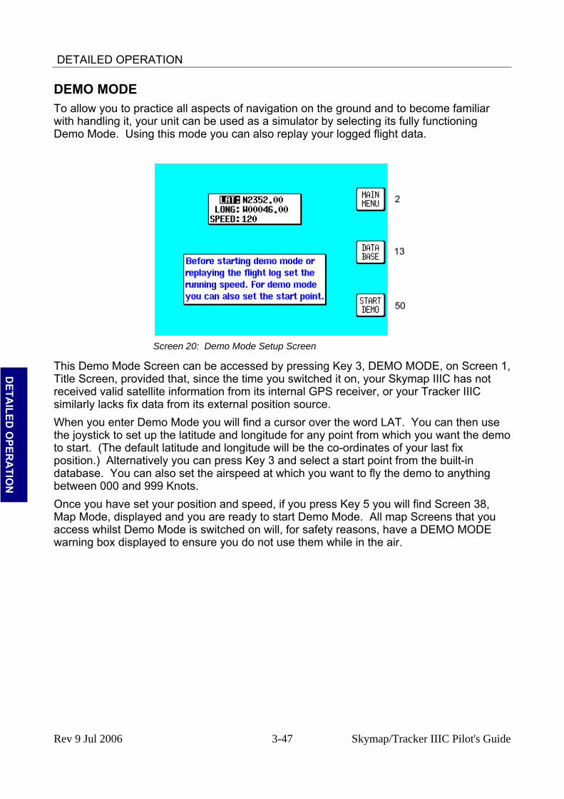
DETAILED OPERATION
DEMO MODE To allow you to practice all aspects of navigation on the ground and to become familiar with handling it, your unit can be used as a simulator by selecting its fully functioning Demo Mode. Using this mode you can also replay your logged flight data.
Screen 20: Demo Mode Setup Screen
This Demo Mode Screen can be accessed by pressing Key 3, DEMO MODE, on Screen 1, Title Screen, provided that, since the time you switched it on, your Skymap IIIC has not received valid satellite information from its internal GPS receiver, or your Tracker IIIC similarly lacks fix data from its external position source.
D
ETAILED
OPER
ATIO
N
When you enter Demo Mode you will find a cursor over the word LAT. You can then use the joystick to set up the latitude and longitude for any point from which you want the demo to start. (The default latitude and longitude will be the co-ordinates of your last fix position.) Alternatively you can press Key 3 and select a start point from the built-in database. You can also set the airspeed at which you want to fly the demo to anything between 000 and 999 Knots. Once you have set your position and speed, if you press Key 5 you will find Screen 38, Map Mode, displayed and you are ready to start Demo Mode. All map Screens that you access whilst Demo Mode is switched on will, for safety reasons, have a DEMO MODE warning box displayed to ensure you do not use them while in the air.
Rev 9 Jul 2006 3-47 Skymap/Tracker IIIC Pilot's Guide

DETAILED OPERATION
Screen 50: Representation of Screen 47 Showing DEMO MODE Flag
If you wish to replay the flight data logged into your unit, set the airspeed as explained above then press Key 4. Screen 50 will then be displayed with the logged data being replayed at the specified speed. This allows long flight plans to be replayed in fast motion. If Demo Mode is active and you switch to Screen 2, Main Menu Screen, you will see Key 3 is now labelled DEMO OFF and can be used to cancel Demo Mode.
D
ETA
ILED
OPE
RA
TIO
N
Rev 9 Jul 2006 3-48 Skymap/Tracker IIIC Pilot's Guide

DETAILED OPERATION
E6-B CALCULATOR E6-B functions are accessible by pressing Key 3, NOTE PAD, in Main Menu followed by Key 3, E6-B CALC, in the Note Pad Screen. This gives access to Screen 57, E6-B Calculator Screen. This function is not available in Demo Mode.
Screen 57: E6-B Calculator Cover Screen
Key 1 returns you to Screen 2 Main Menu. Key 6 calls Screen 58, the Density Altitude/TAS/Winds Aloft Calculator page.
D
ETAILED
OPER
ATIO
N
Key 7 calls Screen 59, Vertical Navigation page. Key 8 calls Screen 60, Trip/Fuel Planning page. Key 9 calls Screen 61, Sunset/Sunrise Calculator page.
Density Altitude/TAS/Winds Aloft Calculator
Screen 58: Density Altitude, True Air Speed & Winds Aloft Screen
On entry to this Screen a cursor will be positioned over the Indicated Altitude (IALT) data entry field.
Rev 9 Jul 2006 3-49 Skymap/Tracker IIIC Pilot's Guide
DETAILED OPERATION
To calculate Density Altitude (DALT) and True Airspeed (TAS) follow these steps. 1. Enter the indicated altitude reading from your altimeter next to the IALT heading.
Default value on entry to Screen is GPS altitude for Skymap IIIC or 2000 feet for Tracker IIIC if no altitude value is being received from the position source.
7. Move the cursor over the entry field next to the heading IAS/CAS and enter your indicated or calibrated airspeed. Default value on entry to this screen is GPS ground speed.
8. Move the cursor over the entry field next to the heading BARO and enter the atmospheric pressure in either inches of mercury (Hg) or millibars (mb). Default value is 29.92Hg / 1013mb.
9. Move the cursor over the entry field next to the heading TAT and enter the total air temperature read from your external aircraft thermometer in either F or C. Default value on entry to this Screen is 59F/15C.
The calculated density altitude (DALT) and true airspeed (TAS) will now be correctly displayed in the lower half of the Screen. To calculate Winds Aloft (WIND) and Headwind / Tailwind Component (COMP), follow these steps.
1. Ensure you have followed steps one to four above so that TAS has been correctly calculated.
10. Move the cursor over the entry field next to the word HDG and enter the magnetic heading of the aircraft from your compass or DI. Default value on entry to this Screen is GPS track
D
ETAILED
OPER
ATIO
N
11. The wind direction and speed (WIND) along with the head or tailwind component (COMP) will now be displayed in the lower half of the Screen.
When the wind has been calculated and you return to the map Screen by pressing Key 5, MAP, a wind arrow will be displayed on screen, correctly orientated and pointing at the aircraft icon to give a visual representation of the wind direction with respect to the aircraft. The wind arrow will disappear after 30 seconds.
Vertical Navigation (VNAV) VNAV is a function that tells the pilot when to start descending or climbing in order to reach a certain altitude at a certain distance from the next waypoint and is entered by pressing Key 3, VNAV, on Screen 57, E6-B Calculator Cover Screen. This function can only be switched on when a Flight plan is being flown or a DIRECT TO is being executed, in other words, when there is a valid destination waypoint.
Rev 8 Oct 2004 3-50 Skymap/Tracker IIIC Pilot's Guide

DETAILED OPERATION
D
ETAILED
OPER
ATIO
N
Screen 59: V NAV Setup Screen
On entry to Screen 59, if there is no active waypoint the DESTINATION box will read NO WPT. You must have an active waypoint in order to activate VNAV Mode. If there is an active waypoint its name will be shown. Once in the VNAV Screen you must enter the cruise altitude (the altitude FROM which you will descend), the final altitude (the altitude TO which you want to descend), the rate of descent (in FPM feet per minute) and the distance before the upcoming waypoint that you want to achieve the new level BY. On entry to this Screen, the FROM value will default to GPS altitude if your unit is a Skymap IIIC or to 5000 feet if your unit is a Tracker IIIC (or the last set value). The TO value will default to 1500 feet (or the last set value). The BY value will default to 5.0nm (or last set value) and the AT value will default to 500fpm (or last set value). The DESCEND IN box will show an active countdown of the time left before you should start your descent and will be recalculated if you change any of the four variables (FROM, TO, BY, AT) or your groundspeed. If Screen 59 is entered then exited by pressing Key 1, VNAV mode is not activated; the values are simply retained for use later in the flight. If Screen 59 is entered then exited by pressing Key 5, Screen 47, 47A or 47B (NAV Mode)
Rev 9 Jul 2006 3-51 Skymap/Tracker IIIC Pilot's Guide
DETAILED OPERATION
Screen will be displayed with the following changes. 1. Key 5 will now read VNAV OFF and there is a new VNAV message box. 12. If the DESCEND IN counter is greater than 00:00, the new message box will show
DESCEND IN with the counter value. 13. When the DESCEND IN counter reaches 00:00, the alarm will sound and a
message will be displayed across the Screen saying START DESCENT NOW. Key 5 will change to ALARM OFF then back to VNAV OFF. Once Key 5 is hit or the alarm times out, the START DESCENT message will disappear and the VNAV message box will now show ADVISORY ALT: XXXXX ft and count down. The descent angle will be fixed at this point to prevent changes in ground speed from altering the descent profile.
When the advisory altitude is within 500 feet of the TO altitude, the alarm will sound again and a message will be displayed across the Screen saying FINAL ALT IMMINENT. Key 5 will change to ALARM OFF then back to VNAV OFF. Once Key 5 is hit or the alarm times out, the advisory altitude will continue to count down until it reaches the TO altitude. VNAV mode will then cancel automatically. If you wish to perform a DIRECT TO or select a new flight plan the VNAV Mode will need to be cancelled. VNAV can be used for climbing as well as descending. If the FROM altitude is set to a lower value than the TO altitude then everywhere the words DESCENT and DESCEND appear, the word CLIMB will be used instead.
D
ETA
ILED
OPE
RA
TIO
N Trip/Fuel Planning
This feature is entered by pressing Key 4, TRIP/FUEL, on Screen 57, E6-B Calculator Cover Screen, and allows you to call up any flight plan and view the following details about each leg of the flight plan. This feature can also be entered whilst flight plan planning from Screens 11 or 42, Flight Plan Selection Screens.
1. BRG (Initial Track, Magnetic) 14. DIS (Leg Distance) 15. ETE (Leg Time) 16. REQ (Fuel Required for Leg)
And for the total flight plan: 1. DIS (Total Distance) 17. ETE (Total Flight Plan Time) 18. REQ (Total Fuel Required)
All you need to input is your cruising speed and your fuel burn. Fuel burn is entered in units / hour. The units are not important providing you use the same units for fuel flow and fuel quantity. If you fill your aircraft tanks using US gallons (or kilograms), enter your fuel flow in USG/hr (kg/hr).
Rev 9 Jul 2006 3-52 Skymap/Tracker IIIC Pilot's Guide

DETAILED OPERATION
Screen 60: Trip / Fuel Flight Plan Select Screen
On entry to Screen 60, the cursor will be positioned over the flight plan number. Default speed will be 120 knots or that last set. Default flow/hour will be 6.0 or that last set. Moving the joystick up and down alters the flight plan number. Moving the joystick right moves the cursor down to the leg selection. Moving the joystick left moves the cursor up to the flow and speed settings. When using this function for the first time, move the cursor up to SPEED and set the cruise speed of your aircraft. Move the cursor down to FLOW/HR and set the fuel flow per hour for your aircraft. These settings will be permanently stored for later use.
D
ETAILED
OPER
ATIO
N
Next move the cursor down and select the flight plan you want to perform the calculations for and then move the cursor down again to scroll through the legs of your chosen flight plan. As you scroll through the flight plan, the seven calculated fields in the lower part of the Screen will be updated. The four values grouped together (DIS, BRG, ETE and REQ) are the DIS (Leg Distance), BRG (Initial Track, Magnetic), ETE (Leg Time) and REQ (Fuel required for Leg) for the leg displayed. The three values grouped below (FPLN DIS, ETE and REQ) are the FPLN DIS (Total flight plan distance), ETE (Total flight plan time) and REQ (Total fuel required, no reserve) for the flight plan displayed.
Sunset/Sunrise Calculator. This feature is entered by pressing Key 5, SUNSET/RISE, on Screen 57, E6-B Calculator Cover Screen, and allows you to calculate sunrise and sunset times for any point in the world. You will be asked to input a latitude, longitude and date. The sunrise and sunset time for that date will then be displayed in your local time.
Rev 9 Jul 2006 3-53 Skymap/Tracker IIIC Pilot's Guide
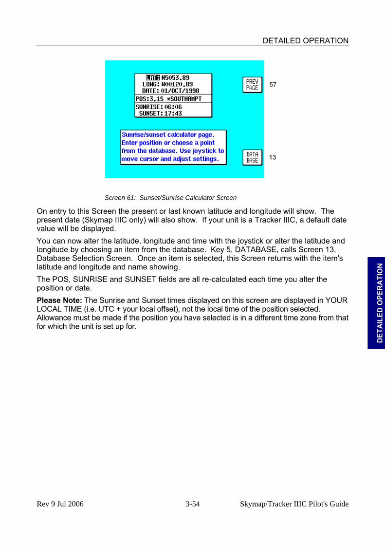
DETAILED OPERATION
Screen 61: Sunset/Sunrise Calculator Screen
On entry to this Screen the present or last known latitude and longitude will show. The present date (Skymap IIIC only) will also show. If your unit is a Tracker IIIC, a default date value will be displayed. You can now alter the latitude, longitude and time with the joystick or alter the latitude and longitude by choosing an item from the database. Key 5, DATABASE, calls Screen 13, Database Selection Screen. Once an item is selected, this Screen returns with the item's latitude and longitude and name showing.
D
ETA
ILED
OPE
RA
TIO
N
The POS, SUNRISE and SUNSET fields are all re-calculated each time you alter the position or date. Please Note: The Sunrise and Sunset times displayed on this screen are displayed in YOUR LOCAL TIME (i.e. UTC + your local offset), not the local time of the position selected. Allowance must be made if the position you have selected is in a different time zone from that for which the unit is set up for.
Rev 9 Jul 2006 3-54 Skymap/Tracker IIIC Pilot's Guide

SETUP SCREENS
A
PPEN
DIC
ES
APPENDIX A SETUP SCREENS
SETUP SCREENS
Screen 21: Setup Cover Screen
Your Bendix/King unit allows you a great deal of flexibility to customise it to suit your own wishes and requirements. It also contains a high level of automatic self-testing and diagnostics. All customisation and diagnostic functions are grouped together in this Setup section. To access Screen 21, Setup Cover Screen press Key 4 SETUP in Main Menu.
Key 1 returns you to Screen 2, Main Menu Key 10 gives access to Screen 22, Map Customisation Screens. Key 11 gives access to Screen 23, NAV Mode Customisation Screen. Key 12 gives access to Screen 24, Personal Identification Number (PIN) Setup
Screens. Key 13 gives access to Screen 28, Installation and Diagnostic Screens.
Map Setup Screens
Rev 9 Jul 2006 A-1 Skymap/Tracker IIIC Pilot's Guide

SETUP SCREENS
Screen 22: Map Customisation Screen
To access Screen 22, Map Customisation Screen, presses Key 4, SETUP, in Main Menu, followed by Key 2, MAP SETUP, in Screen 21, Setup Cover Screen. When this Screen first appears you will always see the current settings with a cursor over the words ORIENTATION. You can then use the joystick to move the cursor up and down the list of headings. When the cursor is over the heading you wish to alter, move the joystick to the right. This will in turn move the cursor over to the set of options available for that heading. Moving the joystick up and down will then allow you to scroll through these options. The various settings available for each heading are listed below. The default settings are those shown in the illustration above. To reset the values on this Screen (or Screens 22A, 22B and 22C) to their defaults, press Key 3 RESET VALUES. This will reset the values on the displayed screen only. In order to reset all user defined data globally, see the Clear Memory screens later in this section. Settings available: ORIENTATION: track up / north up.
A
PPEND
ICES
AIRPORT NAMES: ICAO code / Airport name / City name. MAP UNITS: nautical miles / statute miles / kilometres. COORD SYSTEM: LAT/LON / OSGB / UTM. DISPLAY: landscape standard / landscape inverse / portrait standard / portrait inverse LANGUAGE: English / French / German / Spanish. MIN R/W LENGTH: selectable from 0 to 15 000. R/W SURFACE REQUIRED: hard/soft / hard. EXTENDED TRACK: on / off. AUTO ZOOM: off / on. AUTO DECLUTTER: on / off KEY BEEP: on / off. LOGGING RATE: selectable between 000 (off) and 999 secs. POSITION REF: all data / VOR’s / VOR’s & Airports AIRSPACE ALERT: on / off ORIENTATION: This allows you to choose whether to have the map displayed with north at the top of the screen or orientated to have the aircraft's track aligned up the screen.
Rev 9 Jul 2006 A-2 Skymap/Tracker IIIC Pilot's Guide

SETUP SCREENS
AIRPORT NAMES: This gives you the option of labelling the airport icons on the map with the full names of the airports (long ones truncated to 9 characters), the full names of the city associated with the airport or the ICAO 3 or 4 letter location indicators. MAP UNITS: This allows you to specify the units in which the scale bar and all navigation information will be displayed. If nautical or statute miles are selected, all lengths and altitudes will be reported in feet. If kilometres are selected, all lengths and altitudes will be reported in metres. COORD SYSTEM: This option controls whether the unit operates with reference to Latitude/Longitude or UTM or OSGB grid references DISPLAY: Here you can choose the orientation of the display with respect to the keys. Portrait Std mode is usually selected for leg and yoke-mounted operation. LANGUAGE: Enables you to choose the language in which you would prefer the unit to operate. MIN R/W LENGTH: This allows you to set the minimum length of main runway at the airports, which will be displayed when you ask the unit to display the ten nearest airports. The minimum length can be specified in steps of 1 foot from 0 to 15,000 feet (or meters if map units are set to kilometres). By setting a minimum length you can force the unit to search for those airports with runways, which are equal to or longer than the pre-set minimum length. To disable this filter set the minimum runway length to 00000 feet. R/W SURFACE REQUIRED: R/W Surface Required is also used when searching for the ten nearest airports in map mode, if set to hard/soft, airports with either hard or soft runways will be displayed. If set too hard, only airports with hard runways will be displayed and soft-runway airports ignored. EXT TRACK: If Extended Track is turned on, you will see an extended track line drawn ahead of your present position in the direction of your present track. This can sometimes be useful to see just where the aircraft would end up if the present heading were maintained. Alternatively you can dispense with this map feature simply by selecting EXT TRACK to OFF. AUTO ZOOM: Auto Zoom is a useful function to use as you approach your destination. When flying the last leg of a flight plan or when flying a DIRECT TO, the zoom range is automatically adjusted. The unit selects the lowest zoom setting that will show the destination and the current aircraft position on the same map image. This automatic selection of the optimum zoom range continues until either the final destination is reached, the flight plan or DIRECT TO is cancelled, or the pilot manually adjusts the map zoom by pressing the ZOOM IN or ZOOM OUT keys.
A
PPEN
DIC
ES
AUTO DECLUTTER: This unique feature makes the map more readable in areas of high data density by removing unimportant icon labels. Each time the map is redrawn, the data displayed is built up in layers starting with the least important data classes (towns etc) through to the most important data class (airports). With Auto Declutter switched on as the map is being built, if a higher priority icon label is found to clash with a lower priority icon label already on the screen, the lower priority icon label will be removed. This prevents icon label overlaps and clashes producing a clearer map. KEY BEEP: This allows you to select the beep that occurs when you press a key or move the joystick on or off. LOGGING RATE: This gives you the choice of how often your position is stored in memory for playback in demo mode or to a PC. A setting of 000 switches the logging function off. A Rev 9 Jul 2006 A-3 Skymap/Tracker IIIC Pilot's Guide
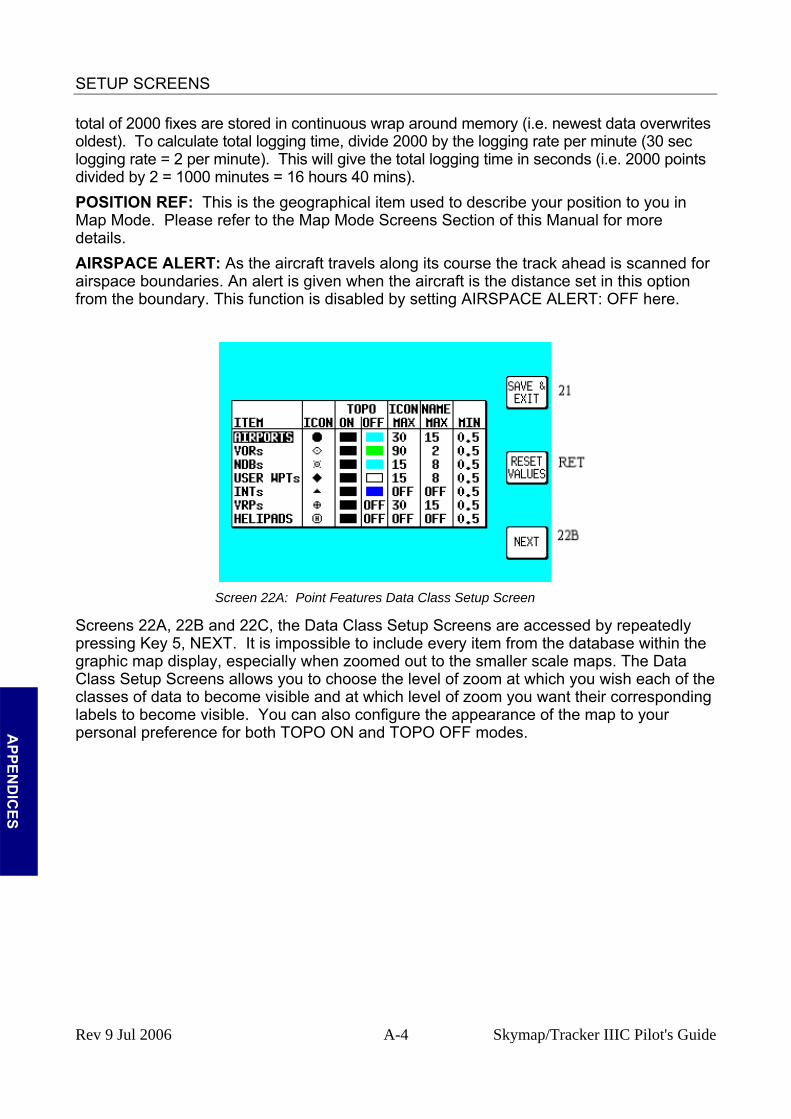
SETUP SCREENS
total of 2000 fixes are stored in continuous wrap around memory (i.e. newest data overwrites oldest). To calculate total logging time, divide 2000 by the logging rate per minute (30 sec logging rate = 2 per minute). This will give the total logging time in seconds (i.e. 2000 points divided by 2 = 1000 minutes = 16 hours 40 mins). POSITION REF: This is the geographical item used to describe your position to you in Map Mode. Please refer to the Map Mode Screens Section of this Manual for more details. AIRSPACE ALERT: As the aircraft travels along its course the track ahead is scanned for airspace boundaries. An alert is given when the aircraft is the distance set in this option from the boundary. This function is disabled by setting AIRSPACE ALERT: OFF here.
Screen 22A: Point Features Data Class Setup Screen
Screens 22A, 22B and 22C, the Data Class Setup Screens are accessed by repeatedly pressing Key 5, NEXT. It is impossible to include every item from the database within the graphic map display, especially when zoomed out to the smaller scale maps. The Data Class Setup Screens allows you to choose the level of zoom at which you wish each of the classes of data to become visible and at which level of zoom you want their corresponding labels to become visible. You can also configure the appearance of the map to your personal preference for both TOPO ON and TOPO OFF modes.
A
PPEND
ICES
Rev 9 Jul 2006 A-4 Skymap/Tracker IIIC Pilot's Guide

SETUP SCREENS
Screen 22B: Cartographical Data Class Setup Screen.
You have the option to select for each database class an ICON or LINE style, A TOPO ON Mode colour, a TOPO OFF Mode colour, an ICON or LINE MAX zoom level (the maximum zoom level at which the icon or line will be displayed), a NAME MAX zoom level (the maximum zoom level at which the name label will be displayed) and a MIN zoom level (the minimum zoom level at which both the icon/line and name will be displayed. The default levels are those shown in the illustrations. You will notice that there is a limited choice of icon styles for some data classes. This is intentional in order to keep the important data (such as airports) displayed in a recognisable form. You will also notice that some settings have N/A in their columns and are not adjustable. These are items that have fixed values and are not configurable by the user. A good example of this is that you cannot set up a colour for the urban areas in TOPO OFF Mode because no cartography is displayed in TOPO OFF Mode. Not all data classes shown in the illustrations are available for all geographic areas, for example VRPs are only included in certain data cards. Details of the data classes available on the data card you have installed are available from Bendix/King.
A
PPEN
DIC
ES
Screen 22C: Line Features Data Class Setup Screen
Rev 9 Jul 2006 A-5 Skymap/Tracker IIIC Pilot's Guide

SETUP SCREENS
Screen 22D: Airspace Data Class Setup Screen Screen 22D: Airspace Data Class Setup Screen
Please think carefully before altering any of the settings on these screens. You may inadvertently switch off an important data class (such as obstacles),
which could compromise your situational awareness.
A
PPEND
ICES
PEND
ICES
Rev 9 Jul 2006 A-6 Skymap/Tracker IIIC Pilot's Guide

SETUP SCREENS
NAV Mode Setup
Screen 23: NAV Mode Customisation Screen
When you first enter this Screen the current settings are displayed with a cursor over the words CDI SCALE. You then have to use the joystick to move the cursor up or down. Once the cursor is over the heading you wish to alter, moving the joystick to the right will move the cursor over to the set of options available for that heading. The various settings available for each heading are listed below. The default settings are those shown in the illustration above. To reset the values on this screen to their defaults, press Key 3 RESET VALUES. This will reset the values on the displayed screen only. In order to reset all user defined data globally, see the Clear Memory screens later in this section. CDI SCALE: 0.3 / 1.0 / 2.5 / 5.0 nm. CDI DISPLAY: bar / numeric / off CDI ALARM: on / off. WPT ALERT: 1 / 2 / 3 / 4 / 5 / 6 / 7 / 8 / 9 / 10 / 11 / 12 / 13 / 14 / 15 / 16 / 17 / 18 / 19 / 20 nm. AUTO LEG SELECT: on / off.
A
PPEN
DIC
ES
AUTO NEXT LEG: on / off. TURN ANTICIPATION: on / off FLIGHT PLAN DISPLAY: all legs / active leg. INTERNAL ALARM: on / off. EXTERNAL ALARM: on / off. CDI SCALE: This enables you to choose which of the given distances you want the unit to use as the setting for the full-scale deflection of the Course Deviation Indicator (CDI) in NAV mode CDI DISPLAY: This allows you to set the CDI display in Map Mode to show either a bar graph, or a numeric read-out of course deviation or to be switched off. If selected OFF, the CDI is no longer shown while you are in Map Mode. CDI ALARM: When selected ON this produces an audible alarm to tell you when full-scale deflection of the CDI has been reached. If you choose to set this to OFF, you disable this alarm. WPT ALERT: You can use this feature to set the distance away from a flight plan turning point, or final destination, at which you wish the audio and visual arrival alarm to be
Rev 9 Jul 2006 A-7 Skymap/Tracker IIIC Pilot's Guide

SETUP SCREENS
activated. AUTO LEG SELECT: If you select this ON, the unit will automatically place the cursor on the closest leg when Screen 12, Flight Plan Program / Edit Screen, is accessed to select the flight plan. Although the nearest leg to your present position is highlighted, an alternative leg may be selected by using the joystick. If AUTO LEG SELECT is switched OFF the cursor will simply be positioned over the first leg in the flight plan whenever Screen 12 is selected. AUTO NEXT LEG: If you select this option ON then, as each waypoint in the flight plan is passed, the next leg will be automatically selected. You thus do not need to press Key 1 (the NEXT LEG Key) as this function produces the same effect automatically. If you select AUTO NEXT LEG to OFF, you will then need to activate the next leg in the flight plan manually by pressing Key 1 (the NEXT LEG Key) at the end of each leg, otherwise your unit will continue to give you distance and bearing information to your previous turning point. TURN ANTICIPATION: Turn Anticipation provides navigation along a curved path segment to ensure a smooth transition between two adjacent legs in the flight plan. If turned ON, Auto Next Leg will also automatically turn on. Auto Next Leg is an essential part of turn anticipation. Please refer to Arrival at an En-route User Waypoint in the Map Mode with NAV Information Screen section of this manual for more details. FLIGHT PLAN DISPLAY: Allows a choice of displaying the full flight plan or just the active leg on the map screen. INTERNAL (ARRIVAL and CDI) ALARM: This gives you the choice between having these internal alarms functioning or inactive. EXTERNAL (ARRIVAL and CDI) ALARM: This gives you the choice to switch ON or OFF the output from the unit, which can drive an external alarm device.
A
PPEND
ICES
Rev 9 Jul 2006 A-8 Skymap/Tracker IIIC Pilot's Guide

SETUP SCREENS
Personal Identification Number (PIN) Setup
Screen 24: PIN Setup Cover Screen
We have provided the security feature of a Personal Identification Number (PIN) in your Bendix/King unit with the main aim of preventing unauthorised persons from using your navigation equipment. You may use this screen to set up your own choice of a four-digit personal number. This can be any permutation of the figures 1, 2, 3, and 4, e.g. 4412, 2433, 3124 etc. To access Screen 24, Pin Setup Cover Screen, press Key 4, SETUP, in Main Menu followed by Key 4, PIN SETUP, in Screen 21, Setup Cover Screen. On entry to this Screen you will find the cursor positioned over the first of four question marks. The joystick is not active and the current four-digit PIN must be entered by pressing Keys 2, 3, 4, and 5 (now labelled 1, 2, 3 and 4 as in the illustration above). The default PIN number that will be set when you receive the unit is 1234. As you enter each number by pressing each of the relevant keys once, in the order that matches the PIN, each question mark in turn is replaced by an asterisk and the cursor moves one step to the right. When the last digit is entered, if you have failed to enter the correct four digits, Screen 25 (see illustration below) will be displayed.
A
PPEN
DIC
ES
Rev 9 Jul 2006 A-9 Skymap/Tracker IIIC Pilot's Guide
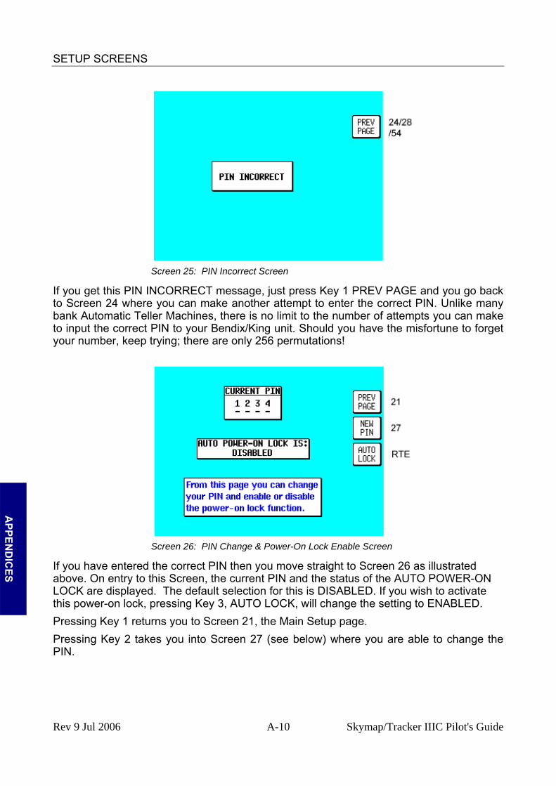
SETUP SCREENS
Screen 25: PIN Incorrect Screen
If you get this PIN INCORRECT message, just press Key 1 PREV PAGE and you go back to Screen 24 where you can make another attempt to enter the correct PIN. Unlike many bank Automatic Teller Machines, there is no limit to the number of attempts you can make to input the correct PIN to your Bendix/King unit. Should you have the misfortune to forget your number, keep trying; there are only 256 permutations!
A
PPEND
ICES
Screen 26: PIN Change & Power-On Lock Enable Screen
If you have entered the correct PIN then you move straight to Screen 26 as illustrated above. On entry to this Screen, the current PIN and the status of the AUTO POWER-ON LOCK are displayed. The default selection for this is DISABLED. If you wish to activate this power-on lock, pressing Key 3, AUTO LOCK, will change the setting to ENABLED. Pressing Key 1 returns you to Screen 21, the Main Setup page. Pressing Key 2 takes you into Screen 27 (see below) where you are able to change the PIN.
Rev 9 Jul 2006 A-10 Skymap/Tracker IIIC Pilot's Guide

SETUP SCREENS
Screen 27: PIN Change Screen
When you access this Screen the cursor will be sitting over the first question mark. This represents the first digit of the PIN. Your new PIN can be entered from here by pressing Keys 2,3,4 or 5 (now labelled 1,2,3, and 4 in the illustration above). The numbers you enter will replace the question marks as they are entered and the cursor will step to the right. When the fourth digit has been entered, the new PIN will automatically be transferred to the unit's Non Volatile Memory (NVM) and Screen 26 will be displayed, showing the newly entered PIN. If you wish, you may press Key 1 at any time and this will take you straight to Screen 26 without making any change to the original PIN. Auto Power-On Lock Pressing Key 3, AUTO LOCK, on Screen 26, Pin Change & Power On Lock Enable Screen, allows you to switch the Auto Power-On Lock security feature ON or OFF. If you ENABLE the Power-On Lock, the unit will require your PIN to be entered every time you or anyone else switches it on. Although, as mentioned above, so long as the Power-On Lock has not been activated, you can key in as many PIN attempts as you wish, once it has been ENABLED however the situation changes entirely.
A
PPEN
DIC
ES If an incorrect PIN is then entered three consecutive times at the switch-on stage, the unit
will lock out and display Screen 55 (see APPENDIX B ). If this happens to you, in order to re-activate the unit, you will have to telephone Honeywell or your Bendix/King dealer, armed with the Serial Number of your unit and the Lock-Out Number, which you can read from the top of Screen 55. The operator at your dealer or at Honeywell will verify these details and check them against the Honeywell database and register of stolen units. Once the operator is satisfied that the unit has not been stolen and that you are the officially recognised owner, you will be given an Unlock Code Number. This Unlock Number is a 10-digit number. In order to unlock your unit you must now enter this number correctly into your unit, still using Screen 55. The digits will replace the question marks as each one is keyed in. The Unlock Number is regarded by the unit as having been entered as soon as the last digit has been keyed in. Every time an incorrect Unlock Number is entered, the unit will generate a new LOCK OUT number. This makes it impossible for a would-be thief to stumble upon the Unlock Number by trial and error. The odds against a thief guessing the correct Unlock Code Number are 10 million to 1.
Rev 9 Jul 2006 A-11 Skymap/Tracker IIIC Pilot's Guide
SETUP SCREENS
If you do ever get into a Lock-Out situation and then re-activate your unit with the Unlock Code Number received from Honeywell, remember that no matter what PIN you were using before, the PIN will now have been reset to the default digits of 1234.
Be very careful if you activate the Auto Power On Lock feature. Locking yourself out of the system can be very inconvenient.
A
PPEND
ICES
Rev 9 Jul 2006 A-12 Skymap/Tracker IIIC Pilot's Guide

SETUP SCREENS
Installation and Diagnostic Screens
Screen 28: Installation and Diagnostics Cover Screen
This Screen is accessed by pressing Key 4, SETUP, in Main Menu followed by Key 5, INST & DIAGS, in Screen 21, Setup Cover Screen. Screen 28 gives you access to all installation and test-related Screens, and allows you to perform diagnostic checks on the data input and output lines. You can also use this Screen to gain full access to the “time in service” logs and “last flight” log. It is used, in addition, to enter four different “Memory Clear” routines, which are PIN-protected to prevent inadvertent erasure to the unit's memory.
Key 1 returns you to Screen 21, Setup Cover Screen. Key 14 calls Screen 63, Screen Position Setup Screen. Key 15 calls Screen 30, Engineering Log Screen. Key 16 calls Screen 32, Memory Clear Entry Screen. Key 17 calls Screen 35, Data In/Out and Test Screen.
A
PPEN
DIC
ES Screen Position Setup
Screen 63 is for use during manufacture to position the picture centrally in the viewable area of the display. This screen is also used to focus the image on the display. It is not a Screen with which you as user of the Skymap IIIC would normally use. This screen is protected by a maintenance PIN number.
Rev 9 Jul 2006 A-13 Skymap/Tracker IIIC Pilot's Guide
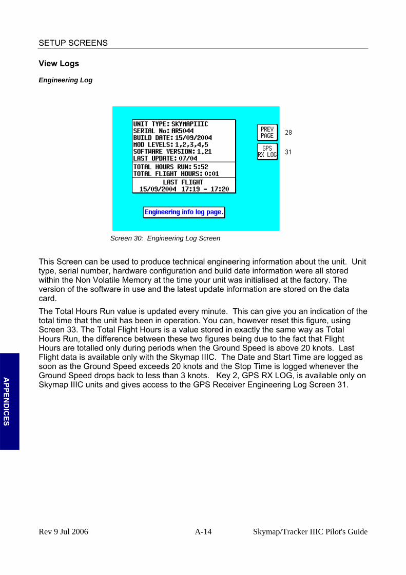
SETUP SCREENS
View Logs
Engineering Log
Screen 30: Engineering Log Screen
This Screen can be used to produce technical engineering information about the unit. Unit type, serial number, hardware configuration and build date information were all stored within the Non Volatile Memory at the time your unit was initialised at the factory. The version of the software in use and the latest update information are stored on the data card. The Total Hours Run value is updated every minute. This can give you an indication of the total time that the unit has been in operation. You can, however reset this figure, using Screen 33. The Total Flight Hours is a value stored in exactly the same way as Total Hours Run, the difference between these two figures being due to the fact that Flight Hours are totalled only during periods when the Ground Speed is above 20 knots. Last Flight data is available only with the Skymap IIIC. The Date and Start Time are logged as soon as the Ground Speed exceeds 20 knots and the Stop Time is logged whenever the Ground Speed drops back to less than 3 knots. Key 2, GPS RX LOG, is available only on Skymap IIIC units and gives access to the GPS Receiver Engineering Log Screen 31.
A
PPEND
ICES
Rev 9 Jul 2006 A-14 Skymap/Tracker IIIC Pilot's Guide
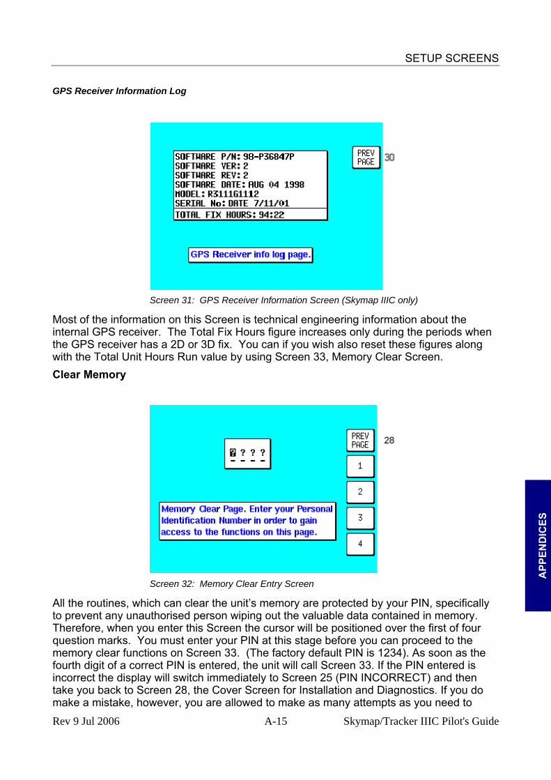
SETUP SCREENS
GPS Receiver Information Log
Screen 31: GPS Receiver Information Screen (Skymap IIIC only)
Most of the information on this Screen is technical engineering information about the internal GPS receiver. The Total Fix Hours figure increases only during the periods when the GPS receiver has a 2D or 3D fix. You can if you wish also reset these figures along with the Total Unit Hours Run value by using Screen 33, Memory Clear Screen. Clear Memory
A
PPEN
DIC
ES
make a mistake, however, you are allowed to make as many attempts as you need to
Screen 32: Memory Clear Entry Screen
All the routines, which can clear the unit’s memory are protected by your PIN, specifically to prevent any unauthorised person wiping out the valuable data contained in memory. Therefore, when you enter this Screen the cursor will be positioned over the first of four question marks. You must enter your PIN at this stage before you can proceed to the memory clear functions on Screen 33. (The factory default PIN is 1234). As soon as the fourth digit of a correct PIN is entered, the unit will call Screen 33. If the PIN entered is incorrect the display will switch immediately to Screen 25 (PIN INCORRECT) and then take you back to Screen 28, the Cover Screen for Installation and Diagnostics. If you do
Rev 9 Jul 2006 A-15 Skymap/Tracker IIIC Pilot's Guide
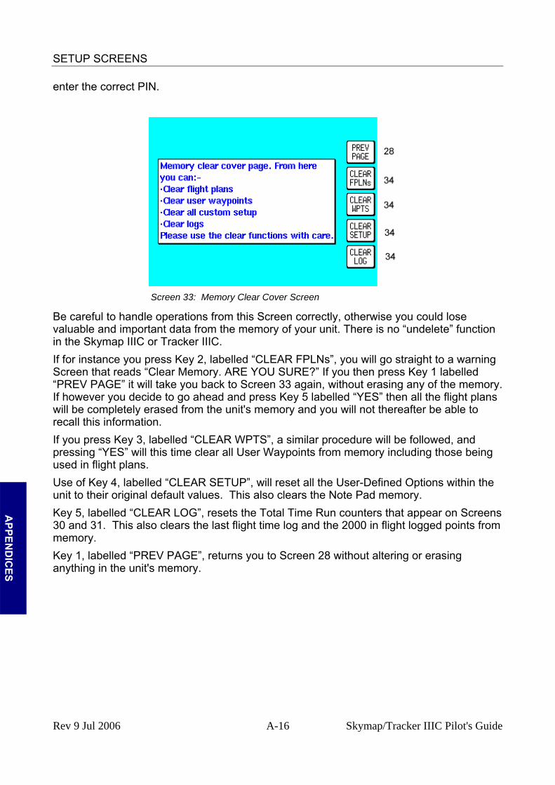
SETUP SCREENS
enter the correct PIN.
Screen 33: Memory Clear Cover Screen
A
PPEND
ICES
Be careful to handle tly, otherwise you could lose ction
lled “CLEAR FPLNs”, you will go straight to a warning
ory.
lled “CLEAR WPTS”, a similar procedure will be followed, and ng
d “CLEAR SETUP”, will reset all the User-Defined Options within the
ar on Screens
elled “PREV PAGE”, returns you to Screen 28 without altering or erasing
operations from this Screen correcvaluable and important data from the memory of your unit. There is no “undelete” funin the Skymap IIIC or Tracker IIIC. If for instance you press Key 2, labeScreen that reads “Clear Memory. ARE YOU SURE?” If you then press Key 1 labelled “PREV PAGE” it will take you back to Screen 33 again, without erasing any of the memIf however you decide to go ahead and press Key 5 labelled “YES” then all the flight plans will be completely erased from the unit's memory and you will not thereafter be able to recall this information. If you press Key 3, labepressing “YES” will this time clear all User Waypoints from memory including those beiused in flight plans. Use of Key 4, labelleunit to their original default values. This also clears the Note Pad memory. Key 5, labelled “CLEAR LOG”, resets the Total Time Run counters that appe30 and 31. This also clears the last flight time log and the 2000 in flight logged points from memory. Key 1, labanything in the unit's memory.
Rev 9 Jul 2006 A-16 Skymap/Tracker IIIC Pilot's Guide
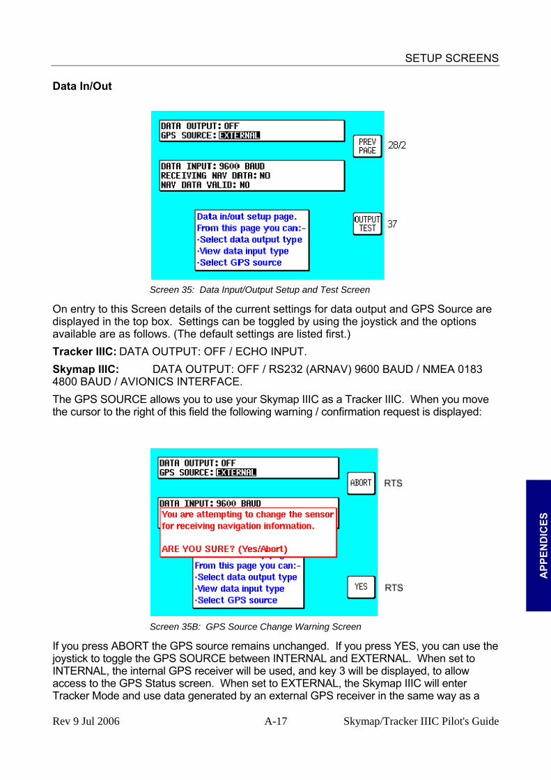
SETUP SCREENS
Data In/Out
Screen 35: Data Input/Output Setup and Test Screen
On entry to this Screen details of the current settings for data output and GPS Source are displayed in the top box. Settings can be toggled by using the joystick and the options available are as follows. (The default settings are listed first.) Tracker IIIC: DATA OUTPUT: OFF / ECHO INPUT. Skymap IIIC: DATA OUTPUT: OFF / RS232 (ARNAV) 9600 BAUD / NMEA 0183 4800 BAUD / AVIONICS INTERFACE. The GPS SOURCE allows you to use your Skymap IIIC as a Tracker IIIC. When you move the cursor to the right of this field the following warning / confirmation request is displayed:
A
PPEN
DIC
ES
Screen 35B: GPS Source Change Warning Screen
If you press ABORT the GPS source remains unchanged. If you press YES, you can use the joystick to toggle the GPS SOURCE between INTERNAL and EXTERNAL. When set to INTERNAL, the internal GPS receiver will be used, and key 3 will be displayed, to allow access to the GPS Status screen. When set to EXTERNAL, the Skymap IIIC will enter Tracker Mode and use data generated by an external GPS receiver in the same way as a
Rev 9 Jul 2006 A-17 Skymap/Tracker IIIC Pilot's Guide

SETUP SCREENS
Tracker IIIC does. If you have a Tracker IIIC and select INTERNAL, an error message will be displayed because an internal GPS receiver will not be found. Data output on Tracker IIIC is limited to echoing the data input. This provides a useful RS232 buffer for connecting other listening devices to your GPS data output. Skymap IIIC can output standard aviation RS232 data at 9600 baud or NMEA 0183 format RMC, GGA and RMB sentences at 4800 baud. See APPENDIX F for full details. The AVIONICS INTERFACE output setting for Skymap IIIC is for use when connected to the Bendix/King Avionics Interface Module (AIM). The AIM is an optional accessory allowing you to connect your Skymap IIIC to other aircraft instruments including the Autopilot. Key 4 will only appear if the AVIONICS INTERFACE output is selected and calls Screen 37, the output test page (Skymap IIIC only). The second box is for information only, and is only shown when the GPS Source is External. The unit will automatically sense the type of incoming data. It first sets up the default data type and then if the incoming data is not recognised, it steps through the other data input options until it finds a format it recognises. The data type the unit is looking for will be displayed next to the DATA INPUT heading. Once a valid format is found, searching will be disabled. Valid data input types are NMEA, AR-NAV (RS 232) and Northstar binary data at either 1200, 4800 or 9600 baud. See the section on Data Input for further details. Once a valid format is recognised and sentences are being decoded, the word YES will be displayed next to RECEIVING DATA. If the data is not recognised or is not present, the word NO will be displayed. If the position information in the data being received is valid and useable, the word YES will appear next to the words DATA VALID, if not then the word NO will be displayed. When Skymap IIIC is used with an external GPS source, the data output will be limited to OFF and ECHO INPUT.
Output Test
A
PPEND
ICES
Screen 37: Aviation Interface Output Test Screen (Skymap IIIC only)
This Screen is designed to output test data to a Bendix/King Avionics Interface Module (AIM) for use during installation and testing. It is not a Screen with which you as user of
Rev 9 Jul 2006 A-18 Skymap/Tracker IIIC Pilot's Guide

SETUP SCREENS
the Skymap IIIC need greatly concern yourself. Should you inadvertently enter it (by pressing Key 4 on Screen 35) you can return to Screen 35 simply by pressing Key 1, labelled PREV PAGE.
A
PPEN
DIC
ES
Rev 9 Jul 2006 A-19 Skymap/Tracker IIIC Pilot's Guide


WARNING SCREENS
APPENDIX B WARNING SCREENS RAM Lost Warning
Screen 51: RAM Lost Warning Screen
This screen is displayed after power-on if any of the RAM areas are found to be corrupted. Key 1 invokes a RAM clear to be carried out on the failed area and the last known good values to be reinstated. If the last known good values are also suspect, a full RAM clear of the affected data will be carried out. Memory Battery Warning
A
PPEND
ICES
Screen 52: Memory Battery Warning Screen
This Screen will appear if during initialisation the memory battery voltage is found to be low. It can also appear at any time during operation if the internal battery falls below a pre-determined limit. By pressing Key 1 you can return to whichever Screen was showing before the low voltage condition was detected. If this screen is displayed, you should have your memory battery replaced by your Bendix/King dealer at the earliest possible opportunity.
Rev 9 Jul 2006 B-1 Skymap/Tracker IIIC Pilot's Guide

WARNING SCREENS
PIN Lock Warning
Screen 54: Power On Security PIN Entry Screen
If the Auto Power-On Lock function has been activated on Screen 26, this Screen will be called during initialisation. You must then input the correct PIN before you are allowed to move back to Screen 1 with full access to all functions. If an incorrect PIN is entered, Screen 25 will appear and Key 1 will revert to this Screen. If an incorrect PIN is entered on three consecutive attempts, even if the unit has been switched off and back on again between attempts, Screen 55 will appear. The number of incorrect attempts that have been made is stored in NVM and increased with each incorrect attempt or cleared down once you have managed to enter the correct PIN. As the PIN is entered, asterisk characters are displayed in place of the question marks. Key 1 can be used as a Back-Space Key. Lock Out Warning
A
PPEN
DIC
ES
Screen 55: Lockout Screen
This Screen will only appear after three incorrect PIN's have been entered on Screen 54 (or if when you switch the unit on the NVM is found to have accumulated three
Rev 9 Jul 2006 B-2 Skymap/Tracker IIIC Pilot's Guide

WARNING SCREENS
unsuccessful PIN input attempts). unsuccessful PIN input attempts). The LOCK OUT number is a random five digit number that the unit generates. This is held in RAM and does not change until an unlock number is entered. The unit can be switched off and on with this Screen showing but the LOCK OUT number will remain the same.
The LOCK OUT number is a random five digit number that the unit generates. This is held in RAM and does not change until an unlock number is entered. The unit can be switched off and on with this Screen showing but the LOCK OUT number will remain the same. If you get locked out of the unit, in order to re-activate the unit, you will need to telephone Honeywell or your local Bendix/King dealer and provide them with your Serial Number and the Lockout Number. Your details will be verified and checked against the Honeywell database and register of stolen units. Once the operator is satisfied that the unit has not been stolen and that you are the officially recognised owner, you will be given an Unlock Code Number.
If you get locked out of the unit, in order to re-activate the unit, you will need to telephone Honeywell or your local Bendix/King dealer and provide them with your Serial Number and the Lockout Number. Your details will be verified and checked against the Honeywell database and register of stolen units. Once the operator is satisfied that the unit has not been stolen and that you are the officially recognised owner, you will be given an Unlock Code Number. This Unlock Code is a 10-digit number. You must enter this into your unit on Screen 55. The digits will replace the question marks as each one is entered. The Unlock Number is deemed to be entered as the last digit is input. Every time an incorrect unlock number is entered, the unit will generate a new LOCK OUT number. This makes it impossible for a would be thief to stumble upon the unlock number by trial and error. The chances of guessing the correct unlock code are 10 million to 1.
This Unlock Code is a 10-digit number. You must enter this into your unit on Screen 55. The digits will replace the question marks as each one is entered. The Unlock Number is deemed to be entered as the last digit is input. Every time an incorrect unlock number is entered, the unit will generate a new LOCK OUT number. This makes it impossible for a would be thief to stumble upon the unlock number by trial and error. The chances of guessing the correct unlock code are 10 million to 1. Once a lock out has occurred and the unit has been re-activated with an unlock number, the PIN will be reset to the default of 1234. Once a lock out has occurred and the unit has been re-activated with an unlock number, the PIN will be reset to the default of 1234.
Be very careful if you activate the Auto Power On Lock feature. Locking yourself out of the system can be very inconvenient.
New Data Card Warning
A
PPEND
ICES
PEND
ICES Screen 56: Flight Plan Change Warning Screen
If, during initialisation, the unit detects a new memory card, the software will check through the flight plans programmed into the unit and validate the data. Whenever you build a flight plan by using items from the memory card, the Name, Lat. and Long of each chosen item is copied into RAM along with a note of which database and which country you selected it from. When a new memory card is detected, each item in each flight plan is checked against the new database. This is done by reading the first item from the first flight plan in RAM and conducting a
Rev 9 Jul 2006 B-3 Skymap/Tracker IIIC Pilot's Guide

WARNING SCREENS
search through the relevant part of the new memory card looking for a name match. If a perfect match is found for the Name, then the Lat. and Long are then checked and if they match correctly also, then no action is required and the software goes on to check the next item. If a discrepancy is found in either Lat. or Long, Screen 56 will appear showing the new information for the waypoint in question. You must confirm that you are aware of the change by pressing Key 1. If no match can be found for the name (i.e. the name has been changed or the item has been deleted from the new database) the Lat. and Long fields on Screen 56 will be left blank and the bottom section of the box will read: CHANGING DATABASE REFERENCE PLEASE CONFIRM Pressing Key 1 will change the database reference displayed on Screen 12, Flight Plan Program/Edit Screen, to OW indicating that this item is now an Old Waypoint and is no longer accessible from any database. This check is carried out for every point in every flight plan and whenever discrepancies are found, Screen 56 will appear on each occasion.
A
PPEN
DIC
ES
Rev 9 Jul 2006 B-4 Skymap/Tracker IIIC Pilot's Guide

MEMORY CARDS
A
PPEND
ICES
APPENDIX C MEMORY CARDS
MEMORY CARDS Data Areas Bendix/King produce a series of memory cards (based on the standard ICAO/ARINC geographic areas) for Skymap IIIC and Tracker IIIC that cover the entire world. Each card for each area contains the operating software, the appropriate Jeppesen aeronautical data and cartographic data to a high resolution. Also included is a low-resolution map of the rest of the world. The ten ICAO/ARINC areas along with their three letter identifiers are:
EUR Europe CAN Canada MES Middle East USA USA PAC Pacific EEU Eastern Europe SPA South Pacific LAM Latin America AFR Africa SAM South America These areas are combined in various ways to produce memory Cards. There are three large area cards available which between them cover the entire world and contain the following data: AMR Americas - comprising CAN, USA, LAM, SAM ATI Atlantic International - comprising EUR, AFR, EEU, MES PAI Pacific International - comprising PAC, SPA, EEU, MES Other area combinations are also available. Please contact your Bendix/King Dealer for full details of data card availability.
Changing the memory card To change the Data Card follow these simple steps:
1. Remove the power/data plug and place the unit face down on a soft surface. A piece of foam or a cushion is ideal. Remove the case back by rotating the two screw fasteners one turn counter clockwise.
Rev 9 Jul 2006 C-1 Skymap/Tracker IIIC Pilot's Guide

MEMORY CARDS
19. Grasp the data card by its edges and pull it straight out of its socket. Do not twist the Card out of the socket, this could bend or break the gold pins. Being careful to align the card with the socket then press the new card firmly into place.
20. Refit the case back being careful that the blue gasket is properly seated. Do not exert undue downward force on the screw fasteners. Let them pull the case back into place. Switch the unit on and check for correct operation. Screen 56 may be displayed if changes to information featured in your flight plans are detected. Please refer to the NAV Data Card Warning in APPENDIX B .
Minimum Safe Altitudes (MSA) Included in the Jeppesen data supplied on your memory card is Grid Minimum Off Route Altitude (Grid MORA) data. The correct use of this data is very important for terrain avoidance and hence requires some further explanation. This data is split into a series of one degree square tiles for the entire world. The Grid MORA provides reference point clearance within these tiles. Jeppesen define a reference point as a natural (peak, knoll, hill, etc) or man-made (tower, stack, tank, building, etc) object. Jeppesen state that Grid MORA values clear all reference points by 1000 feet in areas where the highest reference points are 5000 feet MSL or lower. MORA values clear all reference points by 2000 feet in areas where the highest reference points are 5001 feet MSL or higher. Grid MORAs are defined for all areas. In Skymap IIIC the Grid MORA information is used in two ways to derive Minimum Safe Altitudes (MSA), firstly during flight plan building and secondly during actual flight. Flight Plan building. On screen 12, the Flight Plan Program / Edit Screen, as the cursor is moved up and down the flight plan, the MSA for that leg is shown in a box below the LEG and FPLN info box as [LEG MSA: XXXX]. This value is the highest value Grid MORA found along a ten mile wide corridor (including 5 miles past the waypoint) centred along each leg. Also shown is [FPLN MSA: XXXX] which is the highest value leg MSA for the entire flight plan. During Flight An [MSA:XXXX] box is included on screen 41, the NAV Menu Screen. This displays the highest Grid MORA value within a ten-mile radius of your present position at all times.
A
PPEN
DIC
ES WARNING: The MSA altitudes displayed are advisory in nature only. They
should not be relied upon as the sole source of obstacle and terrain avoidance information. Always refer to current aeronautical charts for appropriate
minimum clearance altitudes.
Rev 9 Jul 2006 C-2 Skymap/Tracker IIIC Pilot's Guide
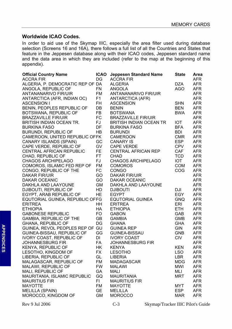
MEMORY CARDS
Worldwide ICAO Codes. In order to aid use of the Skymap IIIC, especially the area filter used during database selection (Screens 16 and 16A), there follows a full list of all the Countries and States that feature in the Jeppesen database along with their ICAO codes, Jeppesen standard name and the data area in which they are included (refer to the map at the beginning of this appendix). Official Country Name ICAO Jeppesen Standard Name State Area ACCRA FIR DG ACCRA FIR AFR ALGERIA, P. DEMOCRATIC REP OF DA ALGERIA DZA AFR ANGOLA, REPUBLIC OF FN ANGOLA AGO AFR ANTANANARIVO FIR/UIR FM ANTANANARIVO FIR/UIR AFR ANTARCTICA (AFR, INDIAN OC) F1 ANTARCTICA (AFR) AFR ASCENSION I FH ASCENSION SHN AFR BENIN, PEOPLES REPUBLIC OF DB BENIN BEN AFR BOTSWANA, REPUBLIC OF FB BOTSWANA BWA AFR BRAZZAVILLE FIR/UIR FC BRAZZAVILLE FIR/UIR AFR BRITISH INDIAN OCEAN TR. FJ BRITISH INDIAN OCEAN TR IOT AFR BURKINA FASO DF BURKINA FASO BFA AFR BURUNDI, REPUBLIC OF HB BURUNDI BDI AFR CAMEROON, UNITED REPUBLIC OF FK CAMEROON CMR AFR CANARY ISLANDS (SPAIN) GC CANARY IS ESP AFR CAPE VERDE, REPUBLIC OF GV CAPE VERDE CPV AFR CENTRAL AFRICAN REPUBLIC FE CENTRAL AFRICAN REP CAF AFR CHAD, REPUBLIC OF FT CHAD TCD AFR CHAGOS ARCHIPELAGO FJ CHAGOS ARCHIPELAGO IOT AFR COMOROS, ISLAMIC FED REP OF FM COMOROS COM AFR CONGO, REPUBLIC OF THE FC CONGO COG AFR DAKAR FIR/UIR GO DAKAR FIR/UIR AFR DAKAR OCEANIC GO DAKAR OCEANIC AFR DAKHLA AND LAAYOUNE GM DAKHLA AND LAAYOUNE AFR DJIBOUTI, REPUBLIC OF HD DJIBOUTI DJI AFR EGYPT, ARAB REPUBLIC OF HE EGYPT EGY AFR EQUTORIAL GUINEA, REPUBLIC OF FG EQUTORIAL GUINEA GNQ AFR ERITREA HH ERITREA ERI AFR ETHIOPIA HA ETHIOPIA ETH AFR GABONESE REPUBLIC FO GABON GAB AFR GAMBIA, REPUBLIC OF THE GB GAMBIA GMB AFR GHANA, REPUBLIC OF DG GHANA GHA AFR GUINEA, REVOL PEOPLES REP OF GU GUINEA REP GIN AFR GUINEA-BISSAU, REPUBLIC OF GG GUINEA-BISSAU GNB AFR IVORY COAST, REPUBLIC OF DI IVORY COAST CIV AFR JOHANNESBURG FIR FA JOHANNESBURG FIR AFR KENYA, REPUBLIC OF HK KENYA KEN AFR LESOTHO, KINGDOM OF FX LESOTHO LSO AFR LIBERIA, REPUBLIC OF GL LIBERIA LBR AFR MALAGASCAR, REPUBLIC OF FM MADAGASCAR MDG AFR MALAWI, REPUBLIC OF FW MALAWI MWI AFR MALI, REPUBLIC OF GA MALI MLI AFR MAURITANIA, ISLAMIC REPUBLIC GQ MAURITANIA MRT AFR MAURITIUS FIR FI MAURITIUS FIR AFR MAYOTTE FM MAYOTTE MYT AFR MELILLA (SPAIN) GE MELILLA ESP AFR MOROCCO, KINGDOM OF GM MOROCCO MAR AFR
A
PPEND
ICES
Rev 9 Jul 2006 C-3 Skymap/Tracker IIIC Pilot's Guide
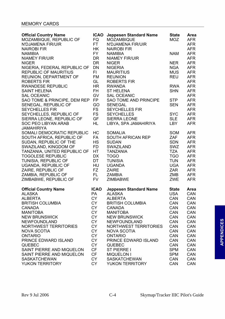
MEMORY CARDS
A
PPEN
DIC
ES
Official Country Name ICAO Jeppesen Standard Name State Area MOZAMBIQUE, REPUBLIC OF FQ MOZAMBIQUE MOZ AFR N'DJAMENA FIR/UIR FT N'DJAMENA FIR/UIR AFR NAIROBI FIR HK NAIROBI FIR AFR NAMIBIA FY NAMIBIA NAM AFR NIAMEY FIR/UIR DR NIAMEY FIR/UIR AFR NIGER DR NIGER NER AFR NIGERIA, FEDERAL REPUBLIC OF DN NIGERIA NGA AFR REPUBLIC OF MAURITIUS FI MAURITIUS MUS AFR REUNION, DEPARTMENT OF FM REUNION REU AFR ROBERTS FIR GL ROBERTS FIR AFR RWANDESE REPUBLIC HR RWANDA RWA AFR SAINT HELENA FH ST HELENA SHN AFR SAL OCEANIC GV SAL OCEANIC AFR SAO TOME & PRINCIPE, DEM REP FP SAO TOME AND PRINCIPE STP AFR SENEGAL, REPUBLIC OF GO SENEGAL SEN AFR SEYCHELLES FIR FS SEYCHELLES FIR AFR SEYCHELLES, REPUBLIC OF FS SEYCHELLES SYC AFR SIERRA LEONE, REPUBLIC OF GF SIERRA LEONE SLE AFR SOC PEO LIBYAN ARAB JAMAHIRIYA
HL LIBYA, SPA JAMAHIRIYA LBY AFR
SOMALI DEMOCRATIC REPUBLIC HC SOMALIA SOM AFR SOUTH AFRICA, REPUBLIC OF FA SOUTH AFRICAN REP ZAF AFR SUDAN, REPUBLIC OF THE HS SUDAN SDN AFR SWAZILAND, KINGDOM OF FD SWAZILAND SWZ AFR TANZANIA, UNITED REPUBLIC OF HT TANZANIA TZA AFR TOGOLESE REPUBLIC DX TOGO TGO AFR TUNISIA, REPUBLIC OF DT TUNISIA TUN AFR UGANDA, REPUBLIC OF HU UGANDA UGA AFR ZAIRE, REPUBLIC OF FZ ZAIRE ZAR AFR ZAMBIA, REPUBLIC OF FL ZAMBIA ZMB AFR ZIMBABWE, REPUBLIC OF FV ZIMBABWE ZWE AFR Official Country Name ICAO Jeppesen Standard Name State Area ALASKA PA ALASKA USA CAN ALBERTA CY ALBERTA CAN CAN BRITISH COLUMBIA CY BRITISH COLUMBIA CAN CAN CANADA CY CANADA CAN CAN MANITOBA CY MANITOBA CAN CAN NEW BRUNSWICK CY NEW BRUNSWICK CAN CAN NEWFOUNDLAND CY NEWFOUNDLAND CAN CAN NORTHWEST TERRITORIES CY NORTHWEST TERRITORIES CAN CAN NOVA SCOTIA CY NOVA SCOTIA CAN CAN ONTARIO CY ONTARIO CAN CAN PRINCE EDWARD ISLAND CY PRINCE EDWARD ISLAND CAN CAN QUEBEC CY QUEBEC CAN CAN SAINT PIERRE AND MIQUELON CF ST PIERRE I SPM CAN SAINT PIERRE AND MIQUELON CF MIQUELON I SPM CAN SASKATCHEWAN CY SASKATCHEWAN CAN CAN YUKON TERRITORY CY YUKON TERRITORY CAN CAN
Rev 9 Jul 2006 C-4 Skymap/Tracker IIIC Pilot's Guide
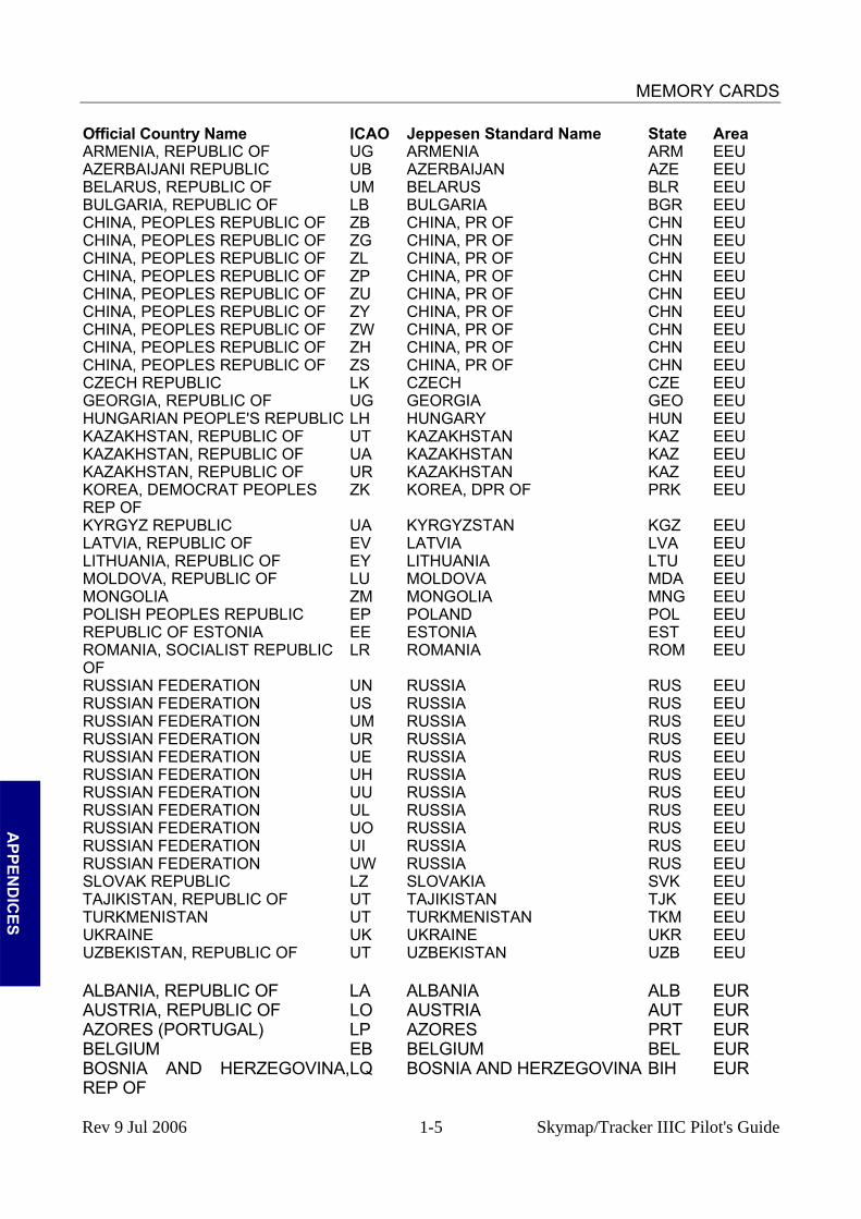
MEMORY CARDS
Official Country Name ICAO Jeppesen Standard Name State Area ARMENIA, REPUBLIC OF UG ARMENIA ARM EEU AZERBAIJANI REPUBLIC UB AZERBAIJAN AZE EEU BELARUS, REPUBLIC OF UM BELARUS BLR EEU BULGARIA, REPUBLIC OF LB BULGARIA BGR EEU CHINA, PEOPLES REPUBLIC OF ZB CHINA, PR OF CHN EEU CHINA, PEOPLES REPUBLIC OF ZG CHINA, PR OF CHN EEU CHINA, PEOPLES REPUBLIC OF ZL CHINA, PR OF CHN EEU CHINA, PEOPLES REPUBLIC OF ZP CHINA, PR OF CHN EEU CHINA, PEOPLES REPUBLIC OF ZU CHINA, PR OF CHN EEU CHINA, PEOPLES REPUBLIC OF ZY CHINA, PR OF CHN EEU CHINA, PEOPLES REPUBLIC OF ZW CHINA, PR OF CHN EEU CHINA, PEOPLES REPUBLIC OF ZH CHINA, PR OF CHN EEU CHINA, PEOPLES REPUBLIC OF ZS CHINA, PR OF CHN EEU CZECH REPUBLIC LK CZECH CZE EEU GEORGIA, REPUBLIC OF UG GEORGIA GEO EEU HUNGARIAN PEOPLE'S REPUBLIC LH HUNGARY HUN EEU KAZAKHSTAN, REPUBLIC OF UT KAZAKHSTAN KAZ EEU KAZAKHSTAN, REPUBLIC OF UA KAZAKHSTAN KAZ EEU KAZAKHSTAN, REPUBLIC OF UR KAZAKHSTAN KAZ EEU KOREA, DEMOCRAT PEOPLES REP OF
ZK KOREA, DPR OF PRK EEU
KYRGYZ REPUBLIC UA KYRGYZSTAN KGZ EEU LATVIA, REPUBLIC OF EV LATVIA LVA EEU LITHUANIA, REPUBLIC OF EY LITHUANIA LTU EEU MOLDOVA, REPUBLIC OF LU MOLDOVA MDA EEU MONGOLIA ZM MONGOLIA MNG EEU POLISH PEOPLES REPUBLIC EP POLAND POL EEU REPUBLIC OF ESTONIA EE ESTONIA EST EEU ROMANIA, SOCIALIST REPUBLIC OF
LR ROMANIA ROM EEU
RUSSIAN FEDERATION UN RUSSIA RUS EEU RUSSIAN FEDERATION US RUSSIA RUS EEU RUSSIAN FEDERATION UM RUSSIA RUS EEU RUSSIAN FEDERATION UR RUSSIA RUS EEU RUSSIAN FEDERATION UE RUSSIA RUS EEU RUSSIAN FEDERATION UH RUSSIA RUS EEU RUSSIAN FEDERATION UU RUSSIA RUS EEU RUSSIAN FEDERATION UL RUSSIA RUS EEU RUSSIAN FEDERATION UO RUSSIA RUS EEU RUSSIAN FEDERATION UI RUSSIA RUS EEU RUSSIAN FEDERATION UW RUSSIA RUS EEU SLOVAK REPUBLIC LZ SLOVAKIA SVK EEU TAJIKISTAN, REPUBLIC OF UT TAJIKISTAN TJK EEU TURKMENISTAN UT TURKMENISTAN TKM EEU UKRAINE UK UKRAINE UKR EEU UZBEKISTAN, REPUBLIC OF UT UZBEKISTAN UZB EEU ALBANIA, REPUBLIC OF LA ALBANIA ALB EUR AUSTRIA, REPUBLIC OF LO AUSTRIA AUT EUR AZORES (PORTUGAL) LP AZORES PRT EUR BELGIUM EB BELGIUM BEL EUR BOSNIA AND HERZEGOVINA,REP OF
LQ BOSNIA AND HERZEGOVINA BIH EUR
A
PPEND
ICES
Rev 9 Jul 2006 1-5 Skymap/Tracker IIIC Pilot's Guide
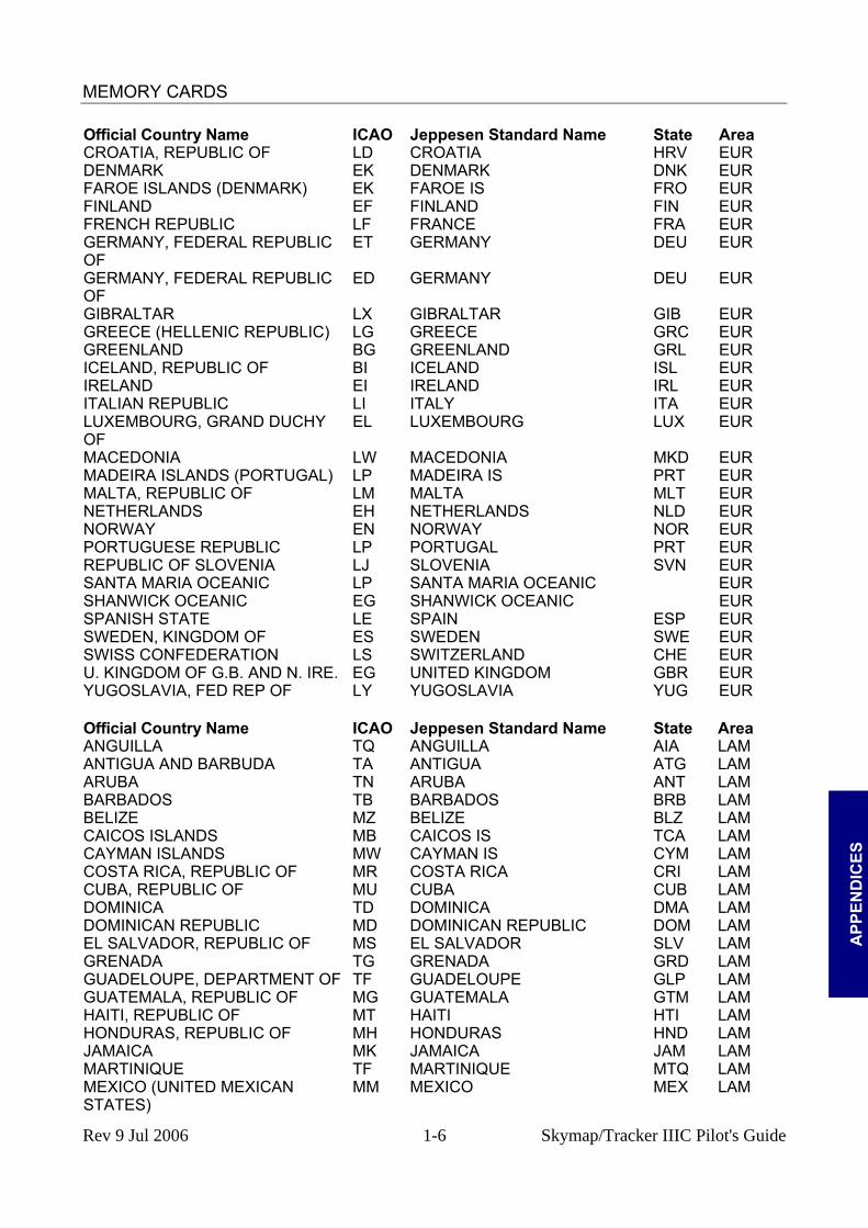
MEMORY CARDS
A
PPEN
DIC
ES
Official Country Name ICAO Jeppesen Standard Name State Area CROATIA, REPUBLIC OF LD CROATIA HRV EUR DENMARK EK DENMARK DNK EUR FAROE ISLANDS (DENMARK) EK FAROE IS FRO EUR FINLAND EF FINLAND FIN EUR FRENCH REPUBLIC LF FRANCE FRA EUR GERMANY, FEDERAL REPUBLIC OF
ET GERMANY DEU EUR
GERMANY, FEDERAL REPUBLIC OF
ED GERMANY DEU EUR
GIBRALTAR LX GIBRALTAR GIB EUR GREECE (HELLENIC REPUBLIC) LG GREECE GRC EUR GREENLAND BG GREENLAND GRL EUR ICELAND, REPUBLIC OF BI ICELAND ISL EUR IRELAND EI IRELAND IRL EUR ITALIAN REPUBLIC LI ITALY ITA EUR LUXEMBOURG, GRAND DUCHY OF
EL LUXEMBOURG LUX EUR
MACEDONIA LW MACEDONIA MKD EUR MADEIRA ISLANDS (PORTUGAL) LP MADEIRA IS PRT EUR MALTA, REPUBLIC OF LM MALTA MLT EUR NETHERLANDS EH NETHERLANDS NLD EUR NORWAY EN NORWAY NOR EUR PORTUGUESE REPUBLIC LP PORTUGAL PRT EUR REPUBLIC OF SLOVENIA LJ SLOVENIA SVN EUR SANTA MARIA OCEANIC LP SANTA MARIA OCEANIC EUR SHANWICK OCEANIC EG SHANWICK OCEANIC EUR SPANISH STATE LE SPAIN ESP EUR SWEDEN, KINGDOM OF ES SWEDEN SWE EUR SWISS CONFEDERATION LS SWITZERLAND CHE EUR U. KINGDOM OF G.B. AND N. IRE. EG UNITED KINGDOM GBR EUR YUGOSLAVIA, FED REP OF LY YUGOSLAVIA YUG EUR Official Country Name ICAO Jeppesen Standard Name State Area ANGUILLA TQ ANGUILLA AIA LAM ANTIGUA AND BARBUDA TA ANTIGUA ATG LAM ARUBA TN ARUBA ANT LAM BARBADOS TB BARBADOS BRB LAM BELIZE MZ BELIZE BLZ LAM CAICOS ISLANDS MB CAICOS IS TCA LAM CAYMAN ISLANDS MW CAYMAN IS CYM LAM COSTA RICA, REPUBLIC OF MR COSTA RICA CRI LAM CUBA, REPUBLIC OF MU CUBA CUB LAM DOMINICA TD DOMINICA DMA LAM DOMINICAN REPUBLIC MD DOMINICAN REPUBLIC DOM LAM EL SALVADOR, REPUBLIC OF MS EL SALVADOR SLV LAM GRENADA TG GRENADA GRD LAM GUADELOUPE, DEPARTMENT OF TF GUADELOUPE GLP LAM GUATEMALA, REPUBLIC OF MG GUATEMALA GTM LAM HAITI, REPUBLIC OF MT HAITI HTI LAM HONDURAS, REPUBLIC OF MH HONDURAS HND LAM JAMAICA MK JAMAICA JAM LAM MARTINIQUE TF MARTINIQUE MTQ LAM MEXICO (UNITED MEXICAN STATES)
MM MEXICO MEX LAM
Rev 9 Jul 2006 1-6 Skymap/Tracker IIIC Pilot's Guide

MEMORY CARDS
A
PPEND
ICES
Official Country Name ICAO Jeppesen Standard Name State Area MONTSERRAT TR MONTSERRAT I MSR LAM NETHERLANDS ANTILLES TN NETH ANTILLES ANT LAM NICARAGUA, REPUBLIC OF MN NICARAGUA NIC LAM PANAMA, REPUBLIC OF MP PANAMA PAN LAM PUERTO RICO TJ PUERTO RICO PRI LAM SAINT KITTS AND NEVIS TK NEVIS I KNA LAM SAINT VINCENT & THE GRENADINES
TV ST VINCENT VCT LAM
SAINT LUCIA TL ST LUCIA LCA LAM SAINT KITTS AND NEVIS TK ST KITTS KNA LAM SAN ANDRES (COLOMBIA) SK SAN ANDRES COL LAM TRINIDAD AND TOBAGO, REP OF TT TOBAGO I TTO LAM TRINIDAD AND TOBAGO, REP OF TT TRINIDAD TTO LAM TURKS AND CAICOS ISLANDS MB TURKS IS TCA LAM VIRGIN ISLANDS OF THE U.S. TI VIRGIN IS VIR LAM VIRGIN ISLANDS, BRITISH TU BRITISH VIRGIN IS VGB LAM Official Country Name ICAO Jeppesen Standard Name State Area AFGHANISTAN OA AFGHANISTAN AFG MES BAHRAIN FIR/UIR OB BAHRAIN FIR/UIR MES BAHRAIN, STATE OF OB BAHRAIN BHR MES BANGLADESH VG BANGLADESH BGD MES BHUTAN, KINGDOM OF VQ BHUTAN BTN MES CYPRUS, REPUBLIC OF LC CYPRUS CYP MES INDIA, REPUBLIC OF VI INDIA IND MES INDIA, REPUBLIC OF VE INDIA IND MES INDIA, REPUBLIC OF VO INDIA IND MES INDIA, REPUBLIC OF VA INDIA IND MES IRAN, ISLAMIC REPUBLIC OF OI IRAN IRN MES IRAQ, REPUBLIC OF OR IRAQ IRQ MES ISRAEL, STATE OF LL ISRAEL ISR MES JEDDAH FIR OE JEDDAH FIR MES JERUSALEM LL JERUSALEM ISR MES JORDAN, HASHEMITE K/DOM OF OJ JORDAN JOR MES KUWAIT, STATE OF OK KUWAIT KWT MES LEBANESE REPUBLIC OL LEBANON LBN MES MALDIVES VR MALDIVES MDV MES NEPAL, KINGDOM OF VN NEPAL NPL MES OMAN, SULTANATE OF OO OMAN OMN MES PAKISTAN, ISLAMIC REPUBLIC OF OP PAKISTAN PAK MES QATAR, STATE OF OT QATAR QAT MES REPUBLIC OF YEMEN OY YEMEN YEM MES SAUDI ARABIA, KINGDOM OF OE SAUDI ARABIA SAU MES SRI LANKA, DEM SOC REP OF VC SRI LANKA LKA MES SYRIAN ARAB REPUBLIC OS SYRIA SYR MES TURKEY, REPUBLIC OF LT TURKEY TUR MES TURKEY, REPUBLIC OF N CYPRUS LC TURKEY (REP OF N CYPRUS) TUR MES UNITED ARAB EMIRATES OM UNITED ARAB EMIRATES ARE MES Official Country Name ICAO Jeppesen Standard Name State Area CAMBODIA, STATE OF VD CAMBODIA KHM PAC CAROLINE ISLANDS PT CAROLINE IS PCI PAC CHINA, THE REPUBLIC OF RC TAIWAN TWN PAC GUAM PG GUAM GUM PAC
Rev 9 Jul 2006 1-7 Skymap/Tracker IIIC Pilot's Guide

MEMORY CARDS
A
PPEN
DIC
ES
Official Country Name ICAO Jeppesen Standard Name State Area HAWAII PH HAWAII USA PAC HONG KONG VH HONG KONG HKG PAC JAPAN RJ JAPAN JPN PAC JAPAN RO JAPAN JPN PAC JOHNSTON ATOLL PJ JOHNSTON ATOLL JTN PAC KIRIBATI PC KIRIBATI KIR PAC KIRIBATI PL KIRIBATI KIR PAC KOREA, REPUBLIC OF RK KOREA KOR PAC LAO, PEOPLES DEM REP OF VL LAOS LAO PAC MACAU VM MACAU MAC PAC MARIANA ISLANDS PG MARIANA IS MNP PAC MARSHALL ISLANDS PK MARSHALL IS MHL PAC MICRONESIA, FED STATES OF PT MICRONESIA FSM PAC MIDWAY ISLANDS PM MIDWAY I MID PAC MYANMAR, UNION OF VY MYANMAR MMR PAC NORTHERN MARIANA ISLANDS PG NORTHERN MARIANA IS MNP PAC OAKLAND OCEANIC CONTROL AREA
P OAKLAND OCTA USA PAC
PALAU, REPUBLIC OF PT PALAU PLW PAC PHILIPPINES, REPUBLIC OF THE RP PHILIPPINES PHL PAC THAILAND, KINGDOM OF VT THAILAND THA PAC VIETNAM, SOCIALIST REP OF VV VIETNAM VNM PAC WAKE ISLAND PW WAKE I XJW PAC Official Country Name ICAO Jeppesen Standard Name State Area ANTARCTICA (ARG, CHILE) S1 ANTARCTICA (ARG, CHILE) SAM ARGENTINA, REPUBLIC OF SA ARGENTINA ARG SAM BOLIVIA, REPUBLIC OF SL BOLIVIA BOL SAM BRAZIL, FED. REPUBLIC OF SB BRAZIL BRA SAM CHILE, REPUBLIC OF SC CHILE CHL SAM COLOMBIA, REPUBLIC OF SK COLOMBIA COL SAM ECUADOR SE ECUADOR ECU SAM FALKLAND ISLANDS SF FALKLAND IS FLK SAM FRENCH GUIANA SO FRENCH GUIANA GUF SAM GUYANA, REPUBLIC OF SY GUYANA GUY SAM PARAGUAY, REPUBLIC OF SG PARAGUAY PRY SAM PERU, REPUBLIC OF SP PERU PER SAM SURINAME, REPUBLIC OF SM SURINAME SUR SAM URUGUAY, REPUBLIC OF SU URUGUAY URY SAM VENEZUELA, REPUBLIC OF SV VENEZUELA VEN SAM Official Country Name ICAO Jeppesen Standard Name State Area ANTARCTICA (AUS, NZ) A1 ANTARCTICA (AUS, NZ) SPA AUSTRALIA YM AUSTRALIA AUS SPA AUSTRALIA YS AUSTRALIA AUS SPA AUSTRALIA YP AUSTRALIA AUS SPA AUSTRALIA YB AUSTRALIA AUS SPA BRUNEI DARUSSALAM WB BRUNEI BRN SPA COOK ISLANDS NC COOK IS COK SPA EASTER ISLAND (CHILE) SC EASTER I CHL SPA FIJI NF FIJI IS FJI SPA FRENCH PACIFIC OVERSEAS TERR.
NT FRENCH PACIFIC PYF SPA
INDONESIA, REPUBLIC OF WA INDONESIA IDN SPA
Rev 9 Jul 2006 1-8 Skymap/Tracker IIIC Pilot's Guide

MEMORY CARDS
A
PPEND
ICES
Official Country Name ICAO Jeppesen Standard Name State Area INDONESIA, REPUBLIC OF WR INDONESIA IDN SPA INDONESIA, REPUBLIC OF WP INDONESIA IDN SPA INDONESIA, REPUBLIC OF WI INDONESIA IDN SPA KIRIBATI NG KIRIBATI KIR SPA MALAYSIA WM MALAYSIA MYS SPA MALAYSIA WB MALAYSIA MYS SPA NAURU, REPUBLIC OF AN NAURU NRU SPA NEW CALEDONIA NW NEW CALEDONIA NCL SPA NEW ZEALAND NZ NEW ZEALAND NZL SPA NIUE NI NIUE NIU SPA PAPUA NEW GUINEA AY PAPUA NEW GUINEA PNG SPA SAMOA, AMERICAN NS AMERICAN SAMOA ASM SPA SAMOA, INDEP STATE OF WESTERN
NS WESTERN SAMOA WSM SPA
SINGAPORE, REPUBLIC OF WS SINGAPORE SGP SPA SOCIETY ISLANDS NT SOCIETY IS PYF SPA SOLOMON ISLANDS AG SOLOMON IS SLB SPA TONGA, KINGDOM OF NF TONGA TON SPA TUAMOTU ISLANDS NT TUAMOTU IS PYF SPA TUVALU NG TUVALU TUV SPA VANUATU, REPUBLIC OF NV VANUATU VUT SPA WALLIS AND FUTUNA ISLANDS NL FUTUNA IS WLF SPA WALLIS AND FUTUNA ISLANDS NL WALLIS IS WLF SPA Official Country Name ICAO Jeppesen Standard Name State Area ALABAMA K7 ALABAMA USA USA ARIZONA K2 ARIZONA USA USA ARKANSAS K4 ARKANSAS USA USA BAHAMAS, COMMONWEALTH OF HE
MY BAHAMAS BHS USA
BERMUDA ISLANDS TX BERMUDA BMU USA CALIFORNIA K2 CALIFORNIA USA USA COLORADO K2 COLORADO USA USA CONNECTICUT K6 CONNECTICUT USA USA DELAWARE K6 DELAWARE USA USA DISTRICT OF COLUMBIA K6 DISTRICT OF COLUMBIA USA USA FLORIDA K7 FLORIDA USA USA GEORGIA K7 GEORGIA USA USA IDAHO K1 IDAHO USA USA ILLINOIS K5 ILLINOIS USA USA INDIANA K5 INDIANA USA USA IOWA K3 IOWA USA USA KANSAS K3 KANSAS USA USA KENTUCKY K5 KENTUCKY USA USA LOUISIANA K4 LOUISIANA USA USA MAINE K6 MAINE USA USA MARYLAND K6 MARYLAND USA USA MASSACHUSETTS K6 MASSACHUSETTS USA USA MICHIGAN K5 MICHIGAN USA USA MINNESOTA K3 MINNESOTA USA USA MISSISSIPPI K7 MISSISSIPPI USA USA MISSOURI K3 MISSOURI USA USA
Rev 9 Jul 2006 1-9 Skymap/Tracker IIIC Pilot's Guide

MEMORY CARDS
A
PPEN
DIC
ES
Official Country Name ICAO Jeppesen Standard Name State Area MONTANA K1 MONTANA USA USA NEBRASKA K3 NEBRASKA USA USA NEVADA K2 NEVADA USA USA NEW MEXICO K2 NEW MEXICO USA USA NEW YORK K6 NEW YORK USA USA NEW HAMPSHIRE K6 NEW HAMPSHIRE USA USA NEW JERSEY K6 NEW JERSEY USA USA NORTH CAROLINA K7 NORTH CAROLINA USA USA NORTH DAKOTA K3 NORTH DAKOTA USA USA OAKLAND OCEANIC CONTROL AREA
K2 UNITED STATES OF AMERICA USA USA
OAKLAND OCEANIC CONTROL AREA
K1 UNITED STATES OF AMERICA USA USA
OHIO K5 OHIO USA USA OKLAHOMA K4 OKLAHOMA USA USA OREGON K1 OREGON USA USA PENNSYLVANIA K6 PENNSYLVANIA USA USA RHODE ISLAND K6 RHODE ISLAND USA USA SOUTH CAROLINA K7 SOUTH CAROLINA USA USA SOUTH DAKOTA K3 SOUTH DAKOTA USA USA TENNESSEE K7 TENNESSEE USA USA TEXAS K4 TEXAS USA USA UNITED STATES OF AMERICA K4 HOUSTON OCEANIC USA USA UNITED STATES OF AMERICA K6 NEW YORK OCEANIC USA USA UNITED STATES OF AMERICA K7 MIAMI OCEANIC USA USA UTAH K2 UTAH USA USA VERMONT K6 VERMONT USA USA VIRGINIA K6 VIRGINIA USA USA WASHINGTON K1 WASHINGTON USA USA WEST VIRGINIA K6 WEST VIRGINIA USA USA WISCONSIN K5 WISCONSIN USA USA WYOMING K1 WYOMING USA USA
Rev 9 Jul 2006 1-10 Skymap/Tracker IIIC Pilot's Guide
HOW DOES GPS WORK?
A
PPEND
ICES
APPENDIX D HOW DOES GPS WORK?
INTRODUCTION TO GPS What Is GPS? Many of the radio-navigation aids used in aviation were originally developed for military use but have now been made freely available to civil users. The Global Positioning System (GPS) has a similar history. The GPS constellation of satellites is an American military facility operated by the US Department of Defence (DoD). This constellation consists of 21 operational satellites plus three spares held in reserve to replace any of the active ones, which might fail. They orbit approximately 10,900 N.M. above the earth in six planes inclined at a 55 degree angle to the Equator and circle the earth twice daily. The orbits are so arranged that a minimum of four satellites will always be visible from any part of the earth's surface at any time. This allows suitable receivers to make extremely accurate determination of latitude, longitude, altitude, velocity and time from satellite signals received by an aircraft, airborne or on the ground.
How Does It Work? Each satellite carries an extremely accurate atomic clock and continuously transmits precise timing waveforms and data concerning its health status and almanac, orbital information and clock timing corrections. The signals have been designed to be extremely resistant to interference from terrestrial radio transmissions, electronic equipment and weather. The technique used to establish position using these satellites is one of simple ranging. In other words, position is calculated from measurements of the distances between the observer and a number of satellites. The exact position of each satellite at any given time is known. This information is actually transmitted by each satellite every few minutes. The precise time (in relation to Universal Time) that each satellite starts to transmit its coded signal is also known. Given this information and the speed of radio waves through space, it is possible to establish the exact distance from each satellite by simple mathematics. For example, if a car leaves point A at exactly 1 o'clock and travels at sixty miles an hour to point B which it reaches at exactly 2 o'clock, we know the distance between points A and B must be sixty miles. In order to achieve the required degree of accuracy from this technique it would normally be necessary to have an extremely accurate atomic clock built into each receiver as well as each satellite. This would not be viable, as each receiver would then cost tens of thousands of pounds. Instead, an ingenious system is used whereby GPS receivers require to be fitted with only reasonably accurate (and thus low-cost) clocks. This involves two important techniques: 1) Code matching or synchronisation. Each satellite transmits, for civilian use, a unique 1023 bit code. This code is repeated every millisecond (one thousandth of a second). In the receiver, circuitry generates an identical code that is then slid back and forth in time until it exactly matches the code being received from the satellite. When a perfect match is achieved, the time at which the receiver is generating the start bit of the code is recorded. The difference in time (or offset) between the receiver generating the code and the satellite generating the code is therefore measurable because the time at which the satellite should have generated the code is known.
Rev 9 Jul 2006 D-1 Skymap/Tracker IIIC Pilot's Guide

HOW DOES GPS WORK?
This gives a very accurate way of measuring the time differences between transmission and reception of the signals generated by the satellites, but does not help with the need for an absolute time reference. One must bear in mind that if the clock in the receiver were only 100 milliseconds (one tenth of a second) out with respect to universal time, the calculated distance from the satellite would have an error of 1,860 miles. This problem is overcome by a second technique: 2) Making use of an extra satellite. In order to obtain a positional fix in three dimensional space, it is necessary to know the exact distance to each of three satellites. The exact distance is however not known because of the presence of an offset or error in the receiver's clock with respect to universal time. A fix is nevertheless calculated using the three satellites, all be it erroneous. Once this fix is calculated, a second fix is calculated using satellites 2 and 3 in conjunction with a fourth satellite. This is repeated for satellites 3, 4 and 1 then 4, 1 and 2. This gives four calculated points in space. If the four calculated points do not overlap, a timing error must be present. A slight correction is then fed into the receiver's clock and the points are calculated again. They move closer to each other. This process is repeated until all the calculations tie up correctly at the same point. The exact position in three-dimensional space is then known and the offset in the receiver's clock eliminated. Similarly, a two-dimensional fix can be established from three satellites. As a result of this technique the receiver does not initially need to know absolute universal time. All that is needed is a reasonably stable clock for taking relative measurements over the short periods between the signals received from each satellite. An approximate knowledge of universal time is required, to know which satellite to expect in which part of the sky. The first satellite the receiver acquires after switch on usually gives this. The exact universal time is transmitted as part of the almanac and health status data by each satellite. This is then corrected by the receiver for signal transition delay as part of the position fix calculations.
A
PPEN
DIC
ES
Accuracy and Reliability All GPS satellites transmit two separate pseudo-random codes on two different frequencies. The most accurate is the P code, which is transmitted at both 1.2276 GHz (1.2276 thousand million cycles per second) and 1.57542 GHz. The P code is extremely complex and has a repetition rate of one week. This code is restricted to military use only, is capable of supreme accuracy and is supposedly unbreakable. The signal available to civilian users is transmitted on 1.57542 GHz only and is called the C/A code. C/A stands for Coarse Acquisition. This code is relatively simple compared to the P code and has a repetition rate of one millisecond. The present maximum accuracy for receivers using the C/A code is 15 meters.
Rev 9 Jul 2006 D-2 Skymap/Tracker IIIC Pilot's Guide

HOW DOES GPS WORK?
There is the possibility however of this being intentionally degraded (by feeding random errors into the satellite clocks) to 100 meters for strategic reasons. This is called Selective Availability or S/A and can be implemented at will by the DoD. Day to day accuracy is monitored by Falcon Air Force Base, Colorado, who receive information from a group of ground stations positioned at Ascension Island, Diego Garcia, Kwagale and Hawaii. These stations receive the satellite signals and check them for timing accuracy. If any errors are detected, error information is transmitted back to the satellite, which then corrects itself. Reliability should be good when the full constellation of 24 satellites are in orbit. Each satellite has three separate clocks on board (one in use and two standby) and in the event of the total failure of a satellite one of the spares already in orbit can be manoeuvred into position within a few hours. The only time the DoD can predict there may be a substantial break in coverage for civilian users, is at a time of National Emergency, when the whole system may be reverted to P code (military) operation only, for strategic reasons. Having said this, the system remained fully available to civilian users during the Gulf conflict.
A
PPEND
ICES
Rev 9 Jul 2006 D-3 Skymap/Tracker IIIC Pilot's Guide
HOW DOES GPS WORK?
THIS PAGE INTENTIONALLY BLANK
A
PPEN
DIC
ES
Rev 9 Jul 2006 D-4 Skymap/Tracker IIIC Pilot's Guide
DIFFERENTIAL FUNCTIONS (Skymap IIIC only)
A
PPEND
ICES
APPENDIX E DIFFERENTIAL FUNCTIONS (Skymap IIIC only) DIFFERENTIAL GPS Your Bendix/King unit has been designed to enable it to make use of Differential GPS (DGPS).
What Is DGPS? GPS on its own is, as we have seen in APPENDIX D , an extremely accurate system for all general navigation purposes. It is not, however, perfect. The most significant source of error in GPS positional calculations is the deliberate downgrading of accuracy known as Selective Availability (SA) described in APPENDIX D . Satellite clocks, although superbly accurate, also have tiny errors, which can affect the accuracy of a fix. So also does any slight drift from a satellite's predicted orbit. The signals from satellites have to pass through the earth's atmosphere and, although radio signals travel at the speed of light, this is only a constant through a vacuum. Things like water vapour in the troposphere and charged particles in the ionosphere do slow down satellite signals and cause slight delays that translate into errors in position. And finally it must be admitted that GPS receivers are not perfect either. These can themselves induce further small positional errors, mainly as a result of receiver noise or clock inaccuracy. DGPS can virtually cancel out all of the errors due to SA, orbital errors and satellite clock inaccuracy. It also greatly reduces any error caused by the atmospheric delay to radio signals. What DGPS cannot correct for are only the inaccuracies due to the GPS receiver itself and possible “multi-path” errors that (like “ghosting” on a TV) are due to secondary signals being received after reflection off local obstructions. The net result of all this is that while standard GPS can experience errors of between 15 and 100 metres (depending largely on whether SA is active or not) DGPS is already capable of accuracy’s down to 1.3 metres horizontally and 2.0 metres vertically. How Does DGPS Work? Any two GPS receivers within a few hundred miles of each other will receive satellite signals that have been affected by virtually the same errors as each other. The signals emanate from the same group of satellites, travel through the same portion of the earth's atmosphere and so will be subjected to the same delays. Thus, all the errors (except those due to multi-pathing and to the receivers themselves) will be common to both. So if one of these receivers is located at a fixed point, which has been extremely and precisely surveyed, it can be used as a reference. Instead of using the signals to calculate its position, since it already knows its position it can calculate the errors in the incoming signals. Having established the magnitude of the errors all that is then needed is an associated transmitter broadcasting signals to tell any mobile GPS receivers in the area exactly what these errors are. The mobile GPS's are then able to use this data to correct for the errors in their raw calculations and to come up with the positional accuracy’s mentioned above. DGPS even removes the deliberate degrading of accuracy associated with the DoD's Selective Availability. It is essential to process the data from the reference receiver very rapidly and to transmit the correction data to the mobile GPS receivers almost instantaneously since, especially if SA is active, these errors are constantly varying. Transmitters and receivers have to be designed to work at high baud (bits per second) rates to transfer the necessary data before it becomes out of date.
Rev 9 Jul 2006 E-1 Skymap/Tracker IIIC Pilot's Guide

DIFFERENTIAL FUNCTIONS (Skymap IIIC only)
Uses Of DGPS Standard GPS provides good accuracy for most navigational tasks, but the additional precision available through DGPS opens up other possibilities in aviation and in many other spheres of activity. Once the aviation authorities are prepared to approve DGPS-based low-visibility approach and landing systems, these could provide low-cost precision facilities worldwide. The benefits of this could be especially useful at small airports where the expense of an ILS or MLS system could never be justified and in developing countries where few if any navigation aids exist today. DGPS has also already become an essential tool of the offshore oil industry, enabling drill bits to be placed with more precision than any other system. Marine navigation, survey work and cartography, emergency services, agriculture and forestry and road transport fleet management are just some of the non-military applications already relying more and more upon the accuracy of DGPS.
Data Connection To operate correctly in differential mode, Skymap IIIC requires a 9600 baud RTCM SVC-104 Version 2.0 format sentence. To connect the Skymap IIIC to a differential receiver unit, connect the 0v or ground lines (pin 5 of the Skymap IIIC connector) and the data output line from the differential receiver to pin 1 of the Skymap IIIC connector. Once connected to an operating differential receiver, switch your Skymap IIIC on and select Screen 3, GPS Status Screen, by pressing Key 1 from the Main Menu Screen. Once the unit has a fix and differential sentences are being decoded, the word DIFFERENTIAL will be displayed next to the STATE: heading. If the data is not recognised or is not present, the word DIFFERENTIAL will not be displayed. All the time that DIFFERENTIAL is displayed, the Skymap IIIC is in differential mode and corrections are being applied to the position fix calculations.
A
PPEN
DIC
ES
Rev 9 Jul 2006 E-2 Skymap/Tracker IIIC Pilot's Guide

SERIAL DATA OUTPUT SENTENCES
A
PPEND
ICES
APPENDIX F SERIAL DATA OUTPUT SENTENCES
SERIAL DATA FORMATS The Skymap IIIC can output standard aviation RS232 data at 9600 baud or NMEA 0183 format RMC, GGA and RMB sentences at 4800 baud. The data output type is setup on Screen 35 Data Input/Output Setup and Test Screen.
NMEA 0183 Data Format The serial format is 4800 baud, 8 data bits, 1 stop bit, no parity. Each sentence is followed by a checksum (*hh), carriage return (CR) and a line feed (LF). All three sentences are sent every two seconds.
NMEA – RMC Sentence $GPRMC,<1>,<2>,<3>,<4>,<5>,<6>,<7>,<8>,<9>,<10>,<11>*hh<CR><LF> <1> UTC time of position fix, hhmmss format. <2> Status, A= Valid position, V=warning <3> Latitude,ddmm.mmm format. <4> Latitude hemisphere, N or S. <5> Longitude, dddmm.mmm format. <6> Longitude hemisphere, E or W. <7> Speed over ground (000.0-999.9 knots). <8> Course over ground (000.0-359.9 true). <9> Date of fix ddmmyy format. <10> Magnetic variation 000.0-180.0o. <11> Variation direction E or W. Sample sentence. $GPRMC,132404,A,5111.465,N,00102.845,W,090.0,304.1,020492,004.3,W*7A
NMEA – GGA Sentence. $GPGGA,<1>,<2>,<3>,<4>,<5>,<6>,<7>,<8>,<9>,M,<10>,M,,*hh<CR><LF> <1> UTC time of position fix, hhmmss. <2> Latitude, ddmm.mmm format. <3> Latitude hemisphere, N or S. <4> Longitude dddmm.mmm format. <5> Longitude hemisphere, E or W. <6> GPS quality. 0 = no fix, 1 = fix good, 2 = fix good, differential mode. <7> Number of sats in use, 00 to 08. <8> DOP, 01.0 to 99.0. <9> Antenna height above MSL (metres). <10> Geoidal offset in metres. Sample sentence. $GPGGA,091636,5119.607,N,00122.001,E,1,04,1.8,18.3,M,-47.0,M,,*5D
NMEA – RMB Sentence $GPRMB,<1>,<2>,<3>,<4>,<5>,<6>,<7>,<8>,<9>,<10>,<11>,<12>,<13>*hhCRLF 1. Position valid (A = valid, V = invalid). 2. XX.XX Cross track error in nautical miles. Rev 9 Jul 2006 F-1 Skymap/Tracker IIIC Pilot's Guide

SERIAL DATA OUTPUT SENTENCES
3. X Direction to steer (L = left, R = right). 4. XXXX Four character start waypoint identifier. (first four characters of name). 5. XXXX Four character destination waypoint identifier. 6. DDMM.MM Destination Lat. 7. X Destination hemisphere (N or S). 8. DDDMM.MM Destination Long. 9. X Destination hemisphere (E or W). 10. XXX.X Range to destination in nautical miles. 11. XXX.X Bearing to destination TRUE. 12. XXX.X closing velocity in knots. 13. X Arrival flag. (A = arrival, V = not arrival). Sample sentence. $GPRMB,A,00.00,L,1,2,5142.20,N,00217.10,W,048.8,304.0,090.0,V*18
Notes on the RMB sentence The direction in field 3 is direction to steer, i.e. off track to the right, steer left. If the unit is not in NAV or DIRECT TO mode, the flag in field 1 will show invalid (V). If the unit is in DIRECT TO mode there will be no start point identifier so field 4 will be blank (spaces). If in DIRECT TO mode where the DIRECT TO point is just a point in space with no name, field 5 will be blank (spaces) also. The arrival flag in field 13 is set to A when the Waypoint Alert message shows on screen and stays set until the next leg is selected even if the Waypoint Passed message comes up on screen. At the end of the flight plan or DIRECT TO when the unit drops out of NAV mode, the flag in field 1 will change to a V. The closing velocity in field 12 is the vectored velocity towards the waypoint. There is no provision for showing negative numbers so if answer is negative, all zeros will be sent.
A
PPEN
DIC
ES
Rev 9 Jul 2006 F-2 Skymap/Tracker IIIC Pilot's Guide

SERIAL DATA OUTPUT SENTENCES
RS-232C AR-NAV Data Format The serial format is 9600 baud 8 data bits, 1 stop bit, no parity. A Type 1 sentence is only sent every two seconds. Each line of data is followed by a carriage return (CR) and a line feed (LF) character except the STX and ETX lines. Header Data Description. STX Hex 02 z aaaaaCRLF GPS altitude in feet. A s dd mmhhCRLF Latitude where s = N or S, dd = degrees, mm = minutes, hh =
hundredths of minutes. B s ddd mmhhCRLF Longitude designated as above. C dddCRLF Magnetic track in whole degrees. D sssCRLF Groundspeed in knots. E dddddCRLF Distance to waypoint in 1/10ths of nm. G snnnnCRLF Cross track error where s = L or R (of track) and nnnn = error in
100ths of an nm. I ddddCRLF Desired magnetic track in 10ths of a degree. i.e. BRG to
waypoint if you were on track. K cccccCRLF Destination waypoint name. Dashes sent after name if shorter
than 5 characters. L ddddCRLF Actual magnetic bearing to WPT (in 1/10ths of a degree). Q sdddCRLF Variation. s= E or W. ddd = 1/10ths degrees. S ----eCRLF e = NAV flag. - = NAV valid, N = NAV not valid. T ---------CRLF Indicates end of sentence type 1. ETX Hex 03. Notes on the AR-NAV sentence. If the unit is not in NAV mode or does not have a fix, dashes (---) will be sent in fields E, G, I, K, L. Part e of field S will be set to N. If the unit does not have a fix, dashes will be sent in the latitude, longitude, track and ground speed fields. If the variation value is greater than 99.9°, a fourth character will be sent in the Q field (i.e. sddddCRLF).
A
PPEND
ICES
Rev 9 Jul 2006 F-3 Skymap/Tracker IIIC Pilot's Guide
SERIAL DATA OUTPUT SENTENCES
THIS PAGE INTENTIONALLY BLANK
A
PPEN
DIC
ES
Rev 9 Jul 2006 F-4 Skymap/Tracker IIIC Pilot's Guide

SERVICE AND WARRANTY
APPENDIX G SERVICE AND WARRANTY Due to the Company's policy of continual development and routine database updates, new Memory Cards will become available every 28 days. As a registered owner of a Tracker IIIC or Skymap IIIC, you will be offered a 1/3/6/12 monthly Memory Card subscription. Keeping your database current is your own responsibility and is extremely important from a safety viewpoint. To validate your warranty you should fill in and return the enclosed Product Registration Card within 10 days of purchase. Failure to register your unit may result in loss of warranty. Registering your unit is also essential if you wish to receive an unlock code over the telephone in the event of a PIN lockout. If your unit is not registered, your only option will be to return the unit to a Bendix/King facility. Registering your unit also provides a means of contacting you with information on any new Memory Card upgrade. If you have a change of address, sell your unit to someone else or if your unit is lost or stolen, please inform us so that we may update our records and keep track of (or help to track down) the unit. Your unit is warranted to be free from defects in materials or workmanship for a period of two years from date of purchase. The warranty will not cover failures due to abuse, misuse, accident or unauthorised alteration or repair. In the unlikely event of repairs being necessary, please return the complete unit, including antenna, in its carrying case, carriage paid to one of the addresses below. Skyforce Avionics Ltd Honeywell Inc 5 The Old Granary Business & General Aviation Boxgrove One Technology Center Chichester 23500 West 105th Street West Sussex Olathe PO18 0ES Kansas United Kingdom USA Tel: +44 (0) 1243 783763 Tel: + 1 913 712 2613 Fax +44 (0) 1243 783992 Fax: + 1 913 712 1302
A
PPEND
ICES
This guarantee does not cover call out or on-site maintenance of the equipment. If you require further help or advice on installing or operating your unit, please contact in the first instance the dealer from whom you purchased the equipment.
Rev 9 Jul 2006 G-1 Skymap/Tracker IIIC Pilot's Guide


SERVICE AND WARRANTY
APPENDIX H PREVIOUS SOFTWARE RELEASES This document has been updated to reflect the features of version 1.22 software. As a
general rule, features introduced on earlier versions of software continue to be supported
on all subsequent versions, but the introduction of new features and enhancements can
mean that screen layouts and some menu items can change from version to version. So
the descriptions and illustrations in this guide may not correspond exactly with your system
if you are using old software.
For convenience, a summary of the differences between the various versions of operating
software is given here. Please note, however, that the software may change with future
versions:
Some of the changes described here correct faults that have been found in earlier versions
of the software. We strongly advise you to use the latest available software at all times.
Software Version
Release Date Features
1.00 1 Dec 1998 Initial release.
1.01 4 Dec 1998 • Does not invite user to set up display of a data type if
there are no examples of that type present in the
databse
• Prevents highlighting of restricted airspace if it is not
displayed at current zoom setting
• Allows selection of USA airfields with or without a leading
K.
• Improved icon highlight labelling
1.02 14 Jan 1999 • Allow user to select database in DEMO mode
• No longer need to re-enter setup variables after
updating software
• Added descriptive pop-up label when airspace is
selected
• The destination turning point on the map screen is now
A
PPEND
ICES
Rev 9 Jul 2006 H-1 Skymap/Tracker IIIC Pilot's Guide
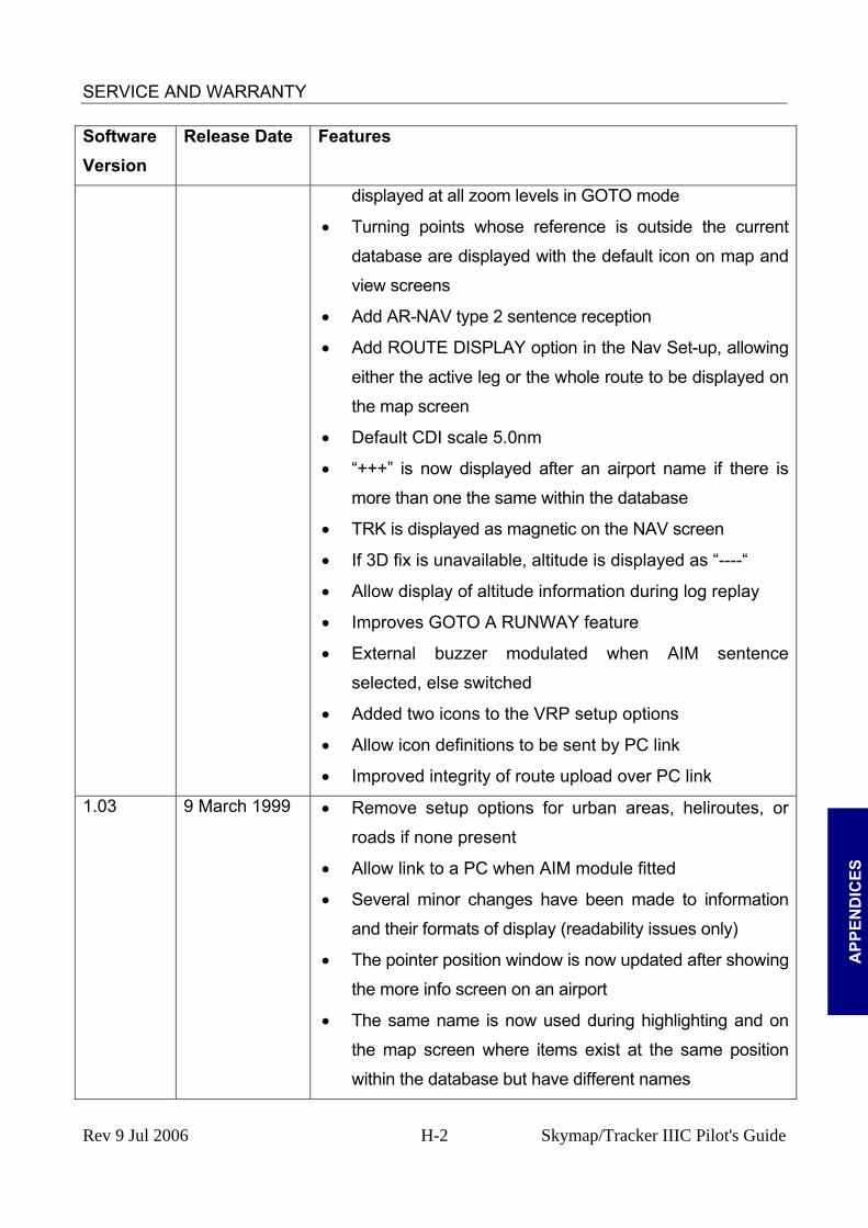
SERVICE AND WARRANTY
A
PPEN
DIC
ES
Software Version
Release Date Features
displayed at all zoom levels in GOTO mode
• Turning points whose reference is outside the current
database are displayed with the default icon on map and
view screens
• Add AR-NAV type 2 sentence reception
• Add ROUTE DISPLAY option in the Nav Set-up, allowing
either the active leg or the whole route to be displayed on
the map screen
• Default CDI scale 5.0nm
• “+++” is now displayed after an airport name if there is
more than one the same within the database
• TRK is displayed as magnetic on the NAV screen
• If 3D fix is unavailable, altitude is displayed as “----“
• Allow display of altitude information during log replay
• Improves GOTO A RUNWAY feature
• External buzzer modulated when AIM sentence
selected, else switched
• Added two icons to the VRP setup options
• Allow icon definitions to be sent by PC link
• Improved integrity of route upload over PC link
1.03 9 March 1999 • Remove setup options for urban areas, heliroutes, or
roads if none present
• Allow link to a PC when AIM module fitted
• Several minor changes have been made to information
and their formats of display (readability issues only)
• The pointer position window is now updated after showing
the more info screen on an airport
• The same name is now used during highlighting and on
the map screen where items exist at the same position
within the database but have different names
Rev 9 Jul 2006 H-2 Skymap/Tracker IIIC Pilot's Guide

SERVICE AND WARRANTY
A
PPEND
ICES
Software Version
Release Date Features
• Now uses the magnetic variation from the AR-NAV input
data when available to ensure consistency with external
GPS
• Improvements in unit operation when configured to work
in Spanish or German
• Route Link now clears when waypoint is cleared
• Screen is now refreshed after coastline and aeronautical
data are displayed when panning
• Improved integrity of upload of User Airports over PC
link
• Waypoint edit screen now allows map to be viewed if
waypoints 1 to 100 are all used
• Flight log now starts at ≥20 knots and stops at <3 knots
to provide greater flexibility for helicopter operations
• Fuel calculations using kilometers and statute miles
corrected
• AIM waypoint alert is cleared at end of route or GOTO
1.04 14 May 1999 • More efficient code allows faster panning and zooming
• Added Large Aircraft, baloon, and helicopter icons for
ownship position
• When ground speed falls below the cut-off point for
track up and the unit reverts to north up, the aircraft icon
is now replaced with the north up style icon
• Current leg route line now fixed at magenta, 3 pixels
wide. Non active leg lines now fixed at solid white, 3
pixels wide. Track line setting on map setup removed.
Extended track line fixed at single dashed white.
• On Nav Setup menu, ALL LEGS is now the default for
route line setting
• Improved logic for highlighting airspace in cases where
Rev 9 Jul 2006 H-3 Skymap/Tracker IIIC Pilot's Guide
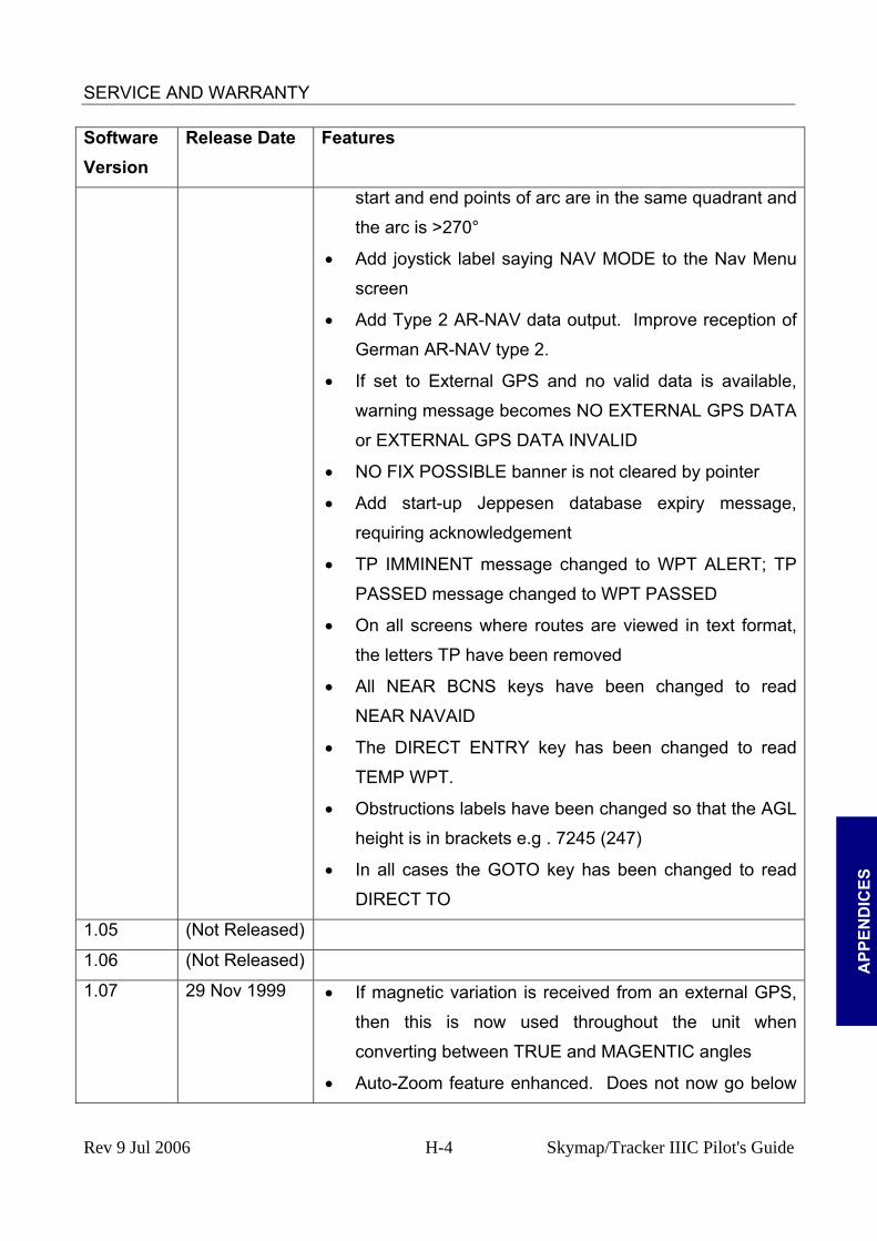
SERVICE AND WARRANTY
A
PPEN
DIC
ES
Software Version
Release Date Features
start and end points of arc are in the same quadrant and
the arc is >270°
• Add joystick label saying NAV MODE to the Nav Menu
screen
• Add Type 2 AR-NAV data output. Improve reception of
German AR-NAV type 2.
• If set to External GPS and no valid data is available,
warning message becomes NO EXTERNAL GPS DATA
or EXTERNAL GPS DATA INVALID
• NO FIX POSSIBLE banner is not cleared by pointer
• Add start-up Jeppesen database expiry message,
requiring acknowledgement
• TP IMMINENT message changed to WPT ALERT; TP
PASSED message changed to WPT PASSED
• On all screens where routes are viewed in text format,
the letters TP have been removed
• All NEAR BCNS keys have been changed to read
NEAR NAVAID
• The DIRECT ENTRY key has been changed to read
TEMP WPT.
• Obstructions labels have been changed so that the AGL
height is in brackets e.g . 7245 (247)
• In all cases the GOTO key has been changed to read
DIRECT TO
1.05 (Not Released)
1.06 (Not Released)
1.07 29 Nov 1999 • If magnetic variation is received from an external GPS,
then this is now used throughout the unit when
converting between TRUE and MAGENTIC angles
• Auto-Zoom feature enhanced. Does not now go below
Rev 9 Jul 2006 H-4 Skymap/Tracker IIIC Pilot's Guide
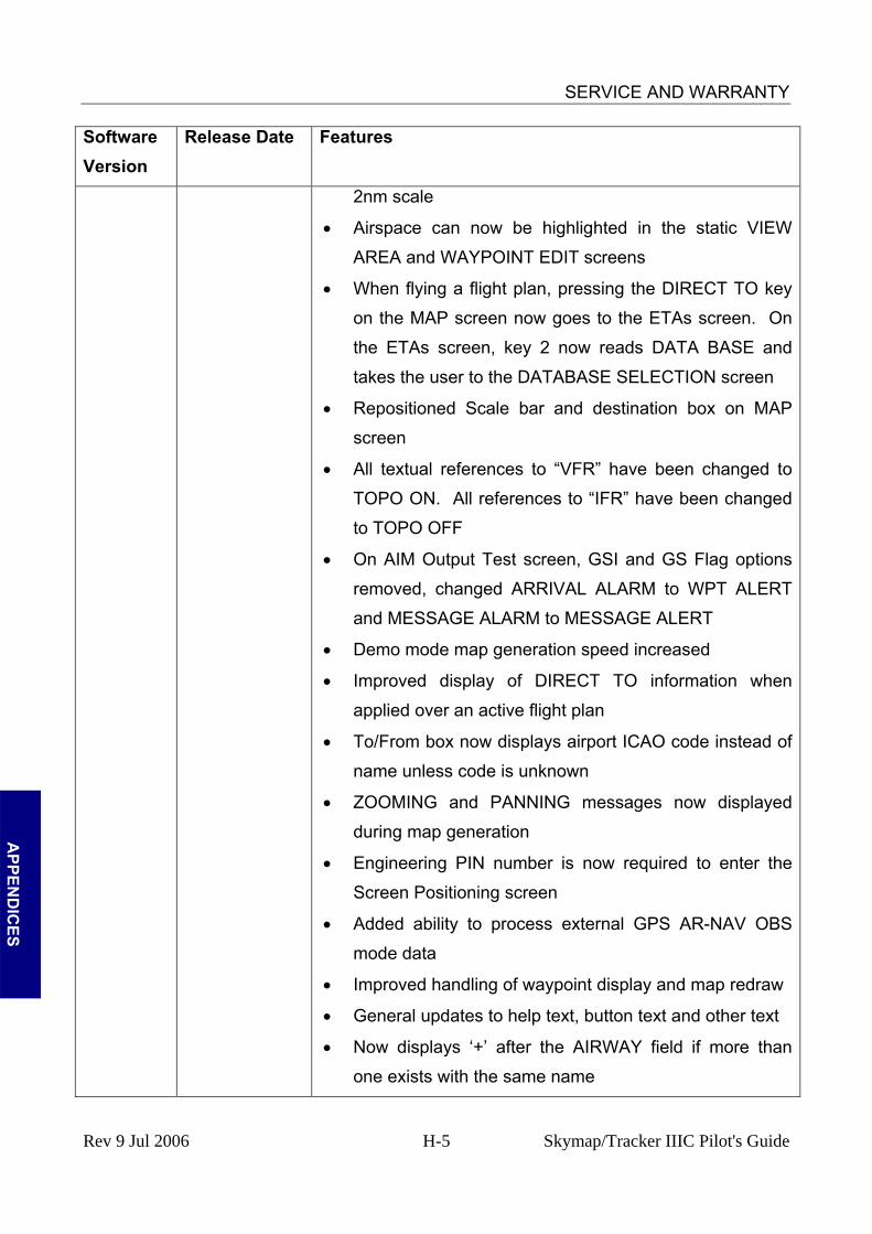
SERVICE AND WARRANTY
A
PPEND
ICES
Software Version
Release Date Features
2nm scale
• Airspace can now be highlighted in the static VIEW
AREA and WAYPOINT EDIT screens
• When flying a flight plan, pressing the DIRECT TO key
on the MAP screen now goes to the ETAs screen. On
the ETAs screen, key 2 now reads DATA BASE and
takes the user to the DATABASE SELECTION screen
• Repositioned Scale bar and destination box on MAP
screen
• All textual references to “VFR” have been changed to
TOPO ON. All references to “IFR” have been changed
to TOPO OFF
• On AIM Output Test screen, GSI and GS Flag options
removed, changed ARRIVAL ALARM to WPT ALERT
and MESSAGE ALARM to MESSAGE ALERT
• Demo mode map generation speed increased
• Improved display of DIRECT TO information when
applied over an active flight plan
• To/From box now displays airport ICAO code instead of
name unless code is unknown
• ZOOMING and PANNING messages now displayed
during map generation
• Engineering PIN number is now required to enter the
Screen Positioning screen
• Added ability to process external GPS AR-NAV OBS
mode data
• Improved handling of waypoint display and map redraw
• General updates to help text, button text and other text
• Now displays ‘+’ after the AIRWAY field if more than
one exists with the same name
Rev 9 Jul 2006 H-5 Skymap/Tracker IIIC Pilot's Guide

SERVICE AND WARRANTY
A
PPEN
DIC
ES
Software Version
Release Date Features
• A thicker dashed line is used on the visual route flight
planning screen
• Handles flight logs of less than 2000 points
• Date and time now stored and extracted from AR-NAV
messages. Time now included in output messages and
a date and time stamp is now applied to flight log entries
• Default colours have changed, and the pointer line has
been changed to CYAN
• Changed information box text for the pointer from DIS
and BRG to PDIS and PBRG respectively
• Reversed operation of heading bug and compass rose
on CDI map screen. Heading bug is now displayed as a
diamond
• Track line length has been increased to 500nm in
external OBS mode
• WPT PASSED message is no longer displayed
continuously in CDI mode
• A warning screen is now displayed before the GPS
SOURCE can be changed
• The default logging rate is now set to zero (off)
• AR-NAV binary waypoint longitude decoded
• When graphically changing a flight plan and a leg is
highlighted, key 2 now reads GRAB LINE. Once this
key is pressed, key reverts to ADD WPT
• When editing a waypoint manually, keys 1 and 5 swap
functionality and key labelled ENTER is changed to
SAVE & EXIT
• ESCAPE key label changed to SAVE & EXIT on
graphical waypoint editing and flight plan screens
• All key label and help text references to ROUTE have
Rev 9 Jul 2006 H-6 Skymap/Tracker IIIC Pilot's Guide
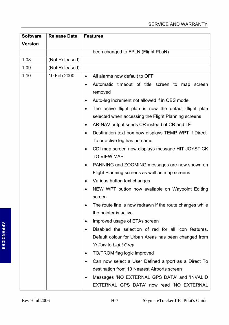
SERVICE AND WARRANTY
A
PPEND
ICES
Software Version
Release Date Features
been changed to FPLN (Flight PLaN)
1.08 (Not Released)
1.09 (Not Released)
1.10 10 Feb 2000 • All alarms now default to OFF
• Automatic timeout of title screen to map screen
removed
• Auto-leg increment not allowed if in OBS mode
• The active flight plan is now the default flight plan
selected when accessing the Flight Planning screens
• AR-NAV output sends CR instead of CR and LF
• Destination text box now displays TEMP WPT if Direct-
To or active leg has no name
• CDI map screen now displays message HIT JOYSTICK
TO VIEW MAP
• PANNING and ZOOMING messages are now shown on
Flight Planning screens as well as map screens
• Various button text changes
• NEW WPT button now available on Waypoint Editing
screen
• The route line is now redrawn if the route changes while
the pointer is active
• Improved usage of ETAs screen
• Disabled the selection of red for all icon features.
Default colour for Urban Areas has been changed from
Yellow to Light Grey
• TO/FROM flag logic improved
• Can now select a User Defined airport as a Direct To
destination from 10 Nearest Airports screen
• Messages ‘NO EXTERNAL GPS DATA’ and ‘INVALID
EXTERNAL GPS DATA’ now read ‘NO EXTERNAL
Rev 9 Jul 2006 H-7 Skymap/Tracker IIIC Pilot's Guide
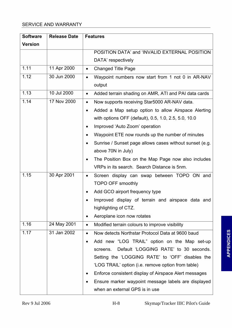
SERVICE AND WARRANTY
A
PPEN
DIC
ES
Software Version
Release Date Features
POSITION DATA’ and ‘INVALID EXTERNAL POSITION
DATA’ respectively
1.11 11 Apr 2000 • Changed Title Page
1.12 30 Jun 2000 • Waypoint numbers now start from 1 not 0 in AR-NAV
output
1.13 10 Jul 2000 • Added terrain shading on AMR, ATI and PAI data cards
1.14 17 Nov 2000 • Now supports receiving Star5000 AR-NAV data.
• Added a Map setup option to allow Airspace Alerting
with options OFF (default), 0.5, 1.0, 2.5, 5.0, 10.0
• Improved ‘Auto Zoom’ operation
• Waypoint ETE now rounds up the number of minutes
• Sunrise / Sunset page allows cases without sunset (e.g.
above 70N in July)
• The Position Box on the Map Page now also includes
VRPs in its search. Search Distance is 5nm.
1.15 30 Apr 2001 • Screen display can swap between TOPO ON and
TOPO OFF smoothly
• Add GCO airport frequency type
• Improved display of terrain and airspace data and
highlighting of CTZ.
• Aeroplane icon now rotates
1.16 24 May 2001 • Modified terrain colours to improve visibility
1.17 31 Jan 2002 • Now detects Northstar Protocol Data at 9600 baud
• Add new “LOG TRAIL” option on the Map set-up
screens. Default ‘LOGGING RATE’ to 30 seconds.
Setting the ‘LOGGING RATE’ to ‘OFF’ disables the
‘LOG TRAIL’ option (i.e. remove option from table)
• Enforce consistent display of Airspace Alert messages
• Ensure marker waypoint message labels are displayed
when an external GPS is in use
Rev 9 Jul 2006 H-8 Skymap/Tracker IIIC Pilot's Guide

SERVICE AND WARRANTY
A
PPEND
ICES
Software Version
Release Date Features
• Suppress extended track line when ground speed is low
in North Up mode
1.18 8 Apr 2002 • Enables initialisation of new LCD Display (hardware
Mod level 2)
• The Screen Alignment page now allows the joystick to
move the screen up and down instead of focus. The
help text has changed to reflect this.
1.19 31 July 2002 • Enable display of AND cartographic data
• Re-instated screen focus on joystick up and down on
Screen Alignment page
1.20 27 Apr 2004 • Enable displaying of ARINC 424-15++ airspace data,
with airspace labelled by class
• Enables use of a new 12-channel internal GPS
(hardware Mod 5)
• The Extended track line has been made thicker, to help
visibility in bright sunlight
• The current leg track line has been given a black outline
so it does not become confused with controlled airspace
• In CDI mode the next Course Box now displays next leg
• Engineering Log Page changed to allow mods to be
identified individually
1.21 22 Jul 2004 • Prevent display of spurious lines at the join between
large inland water features
• N^ (North up) icon always shown when map is
displayed North-Up
• Made entry of negative TAT in the WIND/TAS page
more intuitive
• Logs can be played back at higher simulated speed
than actual aircraft
1.22 18 Feb 2005 • MSA displayed correctly on Nav Menu and Flight
Rev 9 Jul 2006 H-9 Skymap/Tracker IIIC Pilot's Guide

SERVICE AND WARRANTY
A
PPEN
DIC
ES
Software Version
Release Date Features
Planning pages for locations West of 0º and South of
Equator. (ref: Skyforce Service Letter TR/SKY/072)
• Obstacle label no longer displayed with obstacle name
in More Info box
Rev 9 Jul 2006 H-10 Skymap/Tracker IIIC Pilot's Guide

ALPHABETICAL INDEX
ALPHABETICAL INDEXAbbreviations 3 En-route ETA’s 40 AC Power 16 Acronyms 3
EPROM 14 Extended Track 3
ADVISORY ALT 53 Flight Plan 34 Airport Information 28 Flight Plans 18 AIRSPACE ALERT 4 FPLN OFF 19 Airways Flight Planning 25 FPM 52 ALARM OFF 42 almanac 5
Fuel Planning 53
alphabetic 3 fuse 16
alphanumeric 3 Garmin 11
AMR 1 Global Positioning System 1
Antenna 18 GPS 1
AR-NAV 3 GPS ALTITUDE 1
Arrival 43 GPS Receiver 15 ground speed 4
Arrival Alarm 42 ATI 1
GS 28 Help 1
Auto Declutter 3 ICAO 1, 3 AUTO LEG SELECT 8 Icon Information 30 AUTO LOCK 11 icons 14 AUTO NEXT LEG 42, 8 Initialisation 2 Auto Power-On Lock 11 Inserting a Waypoint 20 AUTO ZOOM 3 Installation 13 barometric altitude 3 Battery 1
INVALID EXTERNAL POSITION DATA26
baud 3 Jeppesen 1 landscape 2
Beacon Information 29 local offset 9 bearing to user waypoint 3 care 2
LOCAL OFFSET 6
CDI 44 Lock Out 2 Logs 14
cigarette lighter 16 CLIMB 53
LORAN 11 LRG TXT 32
Coarse Acquisition 2 MAP 26 Course Deviation Indicator 7 Memory Battery 1 cross track error 3 memory cards 1 cursor field 3 database 22
minimum safe altitude 4
Definitions 3 MORA 2 NAV MENU 32
Demo Mode 47 NEAR APTS 37 Density Altitude/ 49 NEAR NAVAID 37 DESCEND IN 52 DGPS 1
New Data Card 3
IN
DEX
Diagnostic 13 NMEA 1
Differential 1 NO EXTERNAL POSITION DATA........26 NO FIX POSSIBLE 26
Dilution of Precision 6 Northstar 11 Direct To 20 DOP 6
Note Pad 3 NVM 14
E6-B Calculator 49 operating system 11 Engineering Log 14 ORIENTATION 2
Rev 9 Jul 2006 Index Skymap/Tracker IIIC Pilot's Guide

ALPHABETICAL INDEX
P code 2 PAI 1
Status 5
PANNING 28 Sunrise 54
PETE 28 Sunset 54
PIN 9 TAS 49 Ten Nearest 36
PIN Lock 2 portrait 2
terminal user waypoints 4
Portrait 11 TOPO OFF 32 TOPO ON 32
position reference 26 Tracker 11 Pseudo CDI 44 RAIM 4
Trimble 11
RAM 14 Turn Anticipation 42 TURN ANTICIPATION 8
RAM Lost 1 REF 19
unlock 1 User Defined Airports 14
RESET STICK 28 RS232 1
User Waypoints 13
satellites 1 UTC 7 Vertical Navigation 51
Screen Orientation 11 VNAV 51 Selective Availability 3 warranty 1 Self Test 2 Setup 1
waypoint 24 Winds Aloft 49
short cuts, 14 WPT ALERT 42 Soft Keying 11 Standard 11
WPT PASSED 42 ZOOM IN, 28
START DESCENT 53 ZOOM OUT 28
IN
DEX
Rev 9 Jul 2006 Index Skymap/Tracker IIIC Pilot's Guide


