This English edition of the EV-97 Eurostar SL Pilotís operating handbook has been translated with care and is accurate to best of our knowledge. However, in all official matters the original Czech text is the authoritative and definite document.
This aeroplane must be operated in compliance with information and limitations contained herein.
This Pilotís operating handbook must be available onboard the aeroplane.
PILOTíS OPERATING HANDBOOK
ii Date of Issue:
02/2008 Revision: Document No.:
EV97SLLPEN
0.1 Record of revisions Any revision of the present manual, except actual weighing data, must be recorded in the following table and in case of approved Sections endorsed by the responsible airworthiness authority. The new or amended text in the revised pages will be indicated by a black vertical line in the left hand margin, and the Revision No. The date will be shown on the left hand bottom of the page.
Rev. No.
Affected Section
Affected Pages
Date Approval Date Date Inserted
Signature
0 ii, iii, iv 4 4-3 7 7-6
1
Valid from S/N 20093511
01/2009
01/2009 Manufact.
0 ii, iii 2 4 4-2, 4-3,
4-4
2/2010
02/2010 Manufact.
0 ii, iii, iv 1 1-1 2 2-3, 2-4
3
7 7-8, 7-9, 7-10, 7-11,
7-12
3/2011
03/2011 Manufact.
03/2011 3
PILOTíS OPERATING HANDBOOK
iii Date of Issue:
02/2008 Revision: Document No.:
EV97SLLPEN
0.2 List of Effective Pages Section Page Date Section Page Date
2 2-0 02/2008 i 02/2008 2-1 02/2008 ii 03/2011 2-2 02/2008 iii 03/2011 2-3 03/2011 iv 03/2011 2-4 03/2011 v 02/2008 2-5 02/2008
1. GENERAL 1.1 Introduction 1.2 Certification basis 1.3 Warnings, cautions and notes 1.4 Descriptive data 1.4.1 Aircraft description 1.4.2 Technical data 1.5 Three-view drawing
PILOTíS OPERATING HANDBOOK
1-1 Date of Issue:
02/2008 Revision: Document No.:
EV97SLLPEN
1.1 Introduction The aeroplane Flight Manual has been prepared to provide pilots and instructors with information for the safe and efficient operation of the EV-97 Eurostar SL ultra-light aeroplane. It also contains supplemental data supplied by the aeroplane manufacturer.
1.2 Certification basis This aircraft type has been approved by the responsible airworthiness authorities listed below: CZECH REPUBLIC Type Certificate No.: ULL ñ 03/98/îdî 00 Date of approval: 2.10.2008
Approved by: Light Aircraft Association of Czech Republic
Certificate of Airworthiness: ìPî
03/2011 3
PILOTíS OPERATING HANDBOOK
1-2 Date of Issue:
02/2008 Revision: Document No.:
EV97SLLPEN
1.3 Warnings, cautions and notes The following definitions apply to warnings, cautions and notes in the flight manual.
WARNING Means that the non-observation of the corresponding procedure leads to an immediate or important degradation of the flight safety.
CAUTION Means that the non-observation of the corresponding procedure leads to a minor or possible long term degradation of the flight safety.
NOTE Draws attention to any special item not directly related to safety, but which is important or unusual.
PILOTíS OPERATING HANDBOOK
1-3 Date of Issue:
02/2008 Revision: Document No.:
EV97SLLPEN
1.4 Descriptive data
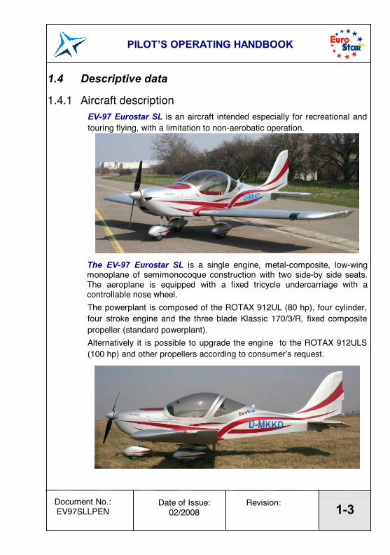
1.4.1 Aircraft description EV-97 Eurostar SL is an aircraft intended especially for recreational and touring flying, with a limitation to non-aerobatic operation.
The EV-97 Eurostar SL is a single engine, metal-composite, low-wing monoplane of semimonocoque construction with two side-by side seats. The aeroplane is equipped with a fixed tricycle undercarriage with a controllable nose wheel. The powerplant is composed of the ROTAX 912UL (80 hp), four cylinder, four stroke engine and the three blade Klassic 170/3/R, fixed composite propeller (standard powerplant). Alternatively it is possible to upgrade the engine to the ROTAX 912ULS (100 hp) and other propellers according to consumerís request.
PILOTíS OPERATING HANDBOOK
1-4 Date of Issue:
02/2008 Revision: Document No.:
EV97SLLPEN
1.4.2 Technical data Wing span ...........................................8.1 m 26.57 ft area ............................................9.84 m2 105.92 ft2 MAC ...........................................1.25 m 4.10 ft loading .....................................45.7 kg/m2 9.37 lb/ft2
Aileron area .................................0.21 m2 2.26 ft2
Flap area .................................0.52 m2 5.60 ft2
Fuselage length..........................................5.98 m 19.62 ft width...........................................1.08 m 3.55 ft height..........................................2.47 m 8,12 ft
Horizontal tail unit span ...........................................2.5 m 8.20 ft area ............................................1.95 m2 20.99 ft2
elevator area...............................0.8 m2 8.60 ft2
Vertical tail unit height..........................................1.28 m 4.21 ft area ............................................1.02 m2 10.93 ft2 rudder area .................................0.43 m2 4.67 ft2
Landing gear wheel track..................................1.6 m 5.25 ft wheel base..................................1.35 m 4.42 ft main wheel diameter ................. 350 mm 14 in nose wheel diameter ..................350 mm 14 in
2.1 Introduction Section 2 includes operating limitations, instrument markings and basic placards necessary for the safe operation of the aircraft, its engine, standard systems and standard equipment.
2.2 Airspeed Airspeed limitations and their operational significance are shown below:
IAS Speed [km/h] [kts]
Remarks
VNE Never exceed speed 270 146
Do not exceed this speed in any operation.
VA Manoeuvring speed 160 86
Do not make full or abrupt control movement above this speed, because under certain conditions the aircraft may be overstressed by full control movement.
VNO Maximum structural
cruising speed 190 103
Do not exceed this speed except in smooth air, and then only with caution.
VFE Maximum Flap. Extending speed 125 67 Do not exceed this speed with
flaps extended.
PILOTíS OPERATING HANDBOOK
2-2 Date of Issue:
02/2008 Revision: Document No.:
EV97SLLPEN
2.3 Airspeed indicator markings Airspeed indicator markings and their colour-code significance are shown below:
IAS value or range Marking [km/h] [kts]
Significance
White arc
58-125 31-67 Positive Flap Operating Range.
Green arc
75-190 40-103 Normal Operating Range.
Yellow arc 190-270 103-146
Manoeuvres must be conducted with caution and only in smooth air.
270 146 Maximum speed for all operations. Red
line 58 31
Stall speed in landing configuration (max. extended flaps, engine on idle)
PILOTíS OPERATING HANDBOOK
2-3 Date of Issue:
02/2008 Revision: Document No.:
EV97SLLPEN
2.4 Powerplant ROTAX 912 engine is installed in the aircraft of S/N
Optimum: 90 ∞C - 110 ∞C 194 - 230∞F 90 ∞C - 110 ∞C 194 - 230∞F Maximum: 7,0 bar Minimum: 1.5 bar 0.8 bar O
il pr
essu
re:
Optimum: 1.5-5.0 bar 2.0-5.0 bar Fuel: see 2.13 Oil: Automotive engine oil of registered brand with gear additives, but
not aircraft oil (refer to engine Operator¥s Manual). API classification ÑSFì or ÑSGì.
Standard Propeller and Manufacturer
V 230C VZL⁄ Praha, Czech Republic
Type: two blade fixed wooden propeller Propeller diameter: 1625 +2
-3 mm 63.98+0.008-0.01 in
Propeller pitch: 18∞20¥ - 18∞55¥
WARNING The Rotax 912 UL has not been certified as an aircraft engine and its failure may occur at any time. The pilot is fully responsible for consequences of such a failure.
2.5
03/2011 3
PILOTíS OPERATING HANDBOOK
2-4 Date of Issue:
02/2008 Revision: Document No.:
EV97SLLPEN
Powerplant instrument markings The analogous powerplant instruments are installed in the EV-97 aeroplane model SL version R, with following colour marking
Function Minimum Limit
(red line)
Normal Operating (green arc)
Caution Range
(yellow arc)
Maximum Range
(red line) Engine speed
(RPM) - 1400-5500 5500-5800 5800
R 912 UL 150 ∞C
(Evans coolant) 128 ∞C
(glycol coolant)
Cylinder Head
Tempe-rature (CHT)
R 912ULS
- - - 135 ∞C (Evans coolant)
128 ∞C (glycol coolant)
R 912 UL 50-90 ∞C
110-140 ∞C 140 ∞C Oil
Tempe-rature R 912ULS
- 50-90 ∞C
110-130 ∞C 130 ∞C
R 912 UL 1.5 bar 1.5 - 5.0 bar 5.0 - 7.0 bar Oil Pressu-
re R 912ULS
0.8 bar 2.0 - 5.0 bar 0.8 ñ 2.0 bar
5.0 - 7.0 bar
7.0 bar cold engine
starting
NOTE
The CHT limit with glycol coolant is 128 ∞C in order to not exceed coolant exit temperature limit 120 ∞C (Operators Manual for ROTAX Engine Type 912 Series ñ Part no. 899374).This limitation is based on Aircraft Manufacturer tests.
NOTE Actual empty weight is stated in SECTION 6, par. 6.2
Max. take-off weight ...................................450 kg 992 lbs
Max landing weight.....................................450 kg 992 lbs
Max. weight of fuel ...................................... 47 kg 104 lbs
Max.baggage weight.................................... 15 kg 33 lbs
2.8 Centre of gravity
Empty aircraft C.G. position (standard).....18±2 % MAC
Operating C.G. range ............................. 20-34 % MAC
2.9 Approved manoeuvres Aeroplane Category: Normal The EV-97 Eurostar SL aeroplane is approved for normal and below listed manoeuvres: ! Steep turns not exceeding 60∞ bank ! Lazy eights ! Chandelles ! Stalls (except whip stalls)
WARNING Aerobatics and intentional spins are prohibited !
PILOTíS OPERATING HANDBOOK
2-7 Date of Issue:
02/2008 Revision: Document No.:
EV97SLLPEN
2.10 Manoeuvring load factors
PILOTíS OPERATING HANDBOOK
2-8 Date of Issue:
02/2008 Revision: Document No.:
EV97SLLPEN
2.11 Crew Minimum crew.................................................. 2 Minimum crew weight......................................55 kg 121 lb Maximum crew weight .............................see 6.2
WARNING Abide with max. take-off weight 450 kg (992 lb)!
2.12 Kinds of operation There are permitted day VFR flights only.
WARNING IFR flights and flights under icing conditions are PROHIBITED!
Instruments and equipment for VFR flights: 1 Airspeed indicator (marked according to 2.3) 1 Altimeter 1 Vertical speed indicator 1 Magnetic compass 1 Bank indicator 2 Safety harnesses
PILOTíS OPERATING HANDBOOK
2-9 Date of Issue:
02/2008 Revision: Document No.:
EV97SLLPEN
2.13 Fuel ! automotive petrol with min RON 95 ! EN 228 Premium ! EN 228 Premium plus ! AVGAS 100 LL
Due to higher lead content in AVGAS, the wear of valve seats and deposits in the combustion chamber and lead sediments in the lubrication system will increase. Therefore, use AVGAS only if you encouter problem with vapour lock or if the other fuel types are not available.
NOTE Use only fuel suitable for the respective climatic zone.
Risk of vapour formation if using winter fuel for summer operation. For other suitable fuel types refer to the engine Operator¥s Manual.
Fuel tank volume...............................65 l 17.2 USgals
Unusable fuel quantity .........................2.9 l 0.77 USgals
2.14 Maximum passenger seating Number of seats.................................................................2
PILOTíS OPERATING HANDBOOK
2-10 Date of Issue:
02/2008 Revision: Document No.:
EV97SLLPEN
2.15 Other limitations No smoking onboard the aeroplane.
PILOTíS OPERATING HANDBOOK
2-11 Date of Issue:
02/2008 Revision: Document No.:
EV97SLLPEN
2.16 Limitation placards CAUTION
The owner (aircraft operating agency) of this aeroplane is responsible for the readability of placards during the aircraft service life.
or
NOTE The values stated on the placard ìLOAD LIMITS,ì are valid for the empty weight of the aircraft with standard equipment installed. The placard with values valid for the actual empty weight of the aircraft will be placed in the cockpit.
3. EMERGENCY PROCEDURES 3.1 Introduction 3.2 Engine failure 3.2.1 Engine failure during take-off run 3.2.2 Engine failure during take-off 3.2.3 Engine failure in flight 3.3 In-Flight start 3.4 Smoke and fire 3.4.1 Fire on ground 3.4.2 Fire during take-off 3.4.3 Fire in flight 3.5 Glide 3.6 Landing emergencies 3.6.1 Emergency landing 3.6.2 Precautionary landing 3.6.3 Landing with a flat tire 3.6.4 Landing with a defective landing gear 3.7 Recovery from unintentional spin 3.8 Other emergencies 3.8.1 Vibration 3.8.2 Carburettor icing
PILOTíS OPERATING HANDBOOK
3-1 Date of Issue:
02/2008 Revision: Document No.:
EV97SLLPEN
3.1 Introduction Section 3 provides checklists and amplified procedures for coping with various emergencies that may occur. Emergencies caused by aircraft or engine malfunction are extremely rare if proper pre-flight inspections and maintenance are practised. However, should an emergency arise, the basic guidelines described in this section should be considered and applied as necessary to correct the problem.
3.2 Engine failure
3.2.1 Engine failure during take-off run 1. Throttle - decrease to idling 2. Ignition - switch off 3. Brake
3.2.2 Engine failure during take-off 1. Speed - gliding at 110 km/h (60 kts) 2. Altitude - below 50 m (160 ft): land in take-off direction
- over 50 m (160 ft): choose landing area 3. Wind - find direction and velocity 4. Landing area - choose free area without obstacles 5. Flaps - extend as needed 6. Fuel cock - shut off 7. Ignition - switch off 8. Propeller - set to the horizontal position by means of starter
(for the two blade propeller) 9. Safety harness - tighten 10. Master switch - switch off before landing 11. Land
NOTE Skip 6-10 if necessary.
PILOTíS OPERATING HANDBOOK
3-2 Date of Issue:
02/2008 Revision: Document No.:
EV97SLLPEN
3.2.3 Engine failure in flight 1. Speed - gliding at 110 km/h (60 kts) 2. Altitude - below 50 m (160 ft): land in flight direction
- over 50 m (160 ft): choose landing area 3. Wind - evaluate direction and velocity 4. Landing area - choose free area without obstacles 5. Flaps - extend if necessary 6. Fuel cock - shut off 7. Ignition - switch off 8. Propeller - set to the horizontal position by means of starter
(for the two blade propeller) 9. Safety harness - tighten 10. Master switch - switch off before landing 11. Land
PILOTíS OPERATING HANDBOOK
3-3 Date of Issue:
02/2008 Revision: Document No.:
EV97SLLPEN
3.3 In-Flight start 1. Speed - gliding at 110 km/h (60 kts, 68 mph) 2. Altitude - check 3. Landing area - choose according to altitude 4. Master switch - switch on 5. Fuel cock - open 6. Electric fuel pump
(if installed) - switch on 7. Choke - as necessary (for cold engine) 8. Throttle - for 1/3 power 9. Ignition box - switch to BOTH and activate starter If the engine cannot be started, increase the flight speed to 200 km/h (110 kts, 124 mph) so that air flow can rotate the propeller, thus enabling the engine to start.
WARNING The loss of altitude during in-flight engine starting is about 400 m (1300 ft) and must be taken into consideration.
3.4 Smoke and fire
3.4.1 Fire on ground 1. Fuel cock - shut off 2. Throttle - full 3. HOT AIR knob
(if installed) - push 4. Master switch - switch off 5. Ignition - switch off 6. Abandon the aeroplane 7. Extinguish fire if it is in your power or call for a fire-brigade.
PILOTíS OPERATING HANDBOOK
3-4 Date of Issue:
02/2008 Revision: Document No.:
EV97SLLPEN
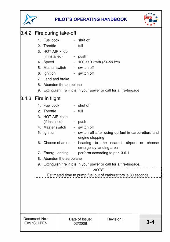
3.4.2 Fire during take-off 1. Fuel cock - shut off 2. Throttle - full 3. HOT AIR knob
(if installed) - push 4. Speed - 100-110 km/h (54-60 kts) 5. Master switch - switch off 6. Ignition - switch off 7. Land and brake 8. Abandon the aeroplane 9. Extinguish fire if it is in your power or call for a fire-brigade
3.4.3 Fire in flight 1. Fuel cock - shut off 2. Throttle - full 3. HOT AIR knob
(if installed) - push 4. Master switch - switch off 5. Ignition - switch off after using up fuel in carburettors and
engine stopping 6. Choose of area - heading to the nearest airport or choose
emergency landing area 7. Emerg. landing - perform according to par. 3.6.1 8. Abandon the aeroplane 9. Extinguish fire if it is in your power or call for a fire-brigade.
NOTE Estimated time to pump fuel out of carburettors is 30 seconds.
PILOTíS OPERATING HANDBOOK
3-5 Date of Issue:
02/2008 Revision: Document No.:
EV97SLLPEN
3.5 Glide An example of the use of gliding is in the case of engine failure. 1. Speed - ~110 km/h (60 kts) 2. Flaps - retracted 3. Instruments - within permitted limits
3.6 Landing emergencies
3.6.1 Emergency landing 1. Emergency landings are generally carried out in the case of engine
failure and the engine cannot be re-started. 2. Speed - 110 km/h (60 kts) 3. Trim - trim the aeroplane 4. Safety harness - tighten 5. Flaps - as needed 6. Radio station - report your location if it is possible 7. Fuel cock - shut off 8. Ignition - switch off 9. Master switch - switch off
PILOTíS OPERATING HANDBOOK
3-6 Date of Issue:
02/2008 Revision: Document No.:
EV97SLLPEN
3.6.2 Precautionary landing A precautionary landing is generally carried out in the cases where the pilot may be dissorientated, the aircraft has no fuel reserve or possibly in bad weather conditions. 1. Choose landing area, determine wind direction 2. Report your plan to land and land area location if a COMM is installed
in the aeroplane 3. Perform low-altitude passage into wind over the right-hand side of the
chosen area with flaps extended to the ìTAKE-OFFì position at a speed of 110 km/h (60 kts) to thoroughly inspect the area.
4. Perform flight around the chosen area 5. Perform an approach at increased idling with fully extended flaps 6. Reduce power to idle run when fly over the runway threshold and
touch-down at the very beginning of the chosen area 7. After stopping the aeroplane switch off all switches, shut off the fuel
cock, lock the aeroplane and look for help NOTE
Watch the chosen area permanently during precautionary landing.
3.6.3 Landing with a flat tire 1. When floating at landing, keep the damaged wheel above ground as
long as possible using the ailerons 2. Maintain the direction at landing run, applying foot control
3.6.4 Landing with a defective landing gear 1. If the main landing gear is damaged, perform touch-down at the
Lowest speed possible and maintain direction at landing run, if possible
2. If the nose wheel is damaged perform touch-down at the Lowest speed possible and hold the nose wheel over a runway by means of the elevator control as long as it is possible
PILOTíS OPERATING HANDBOOK
3-7 Date of Issue:
02/2008 Revision: Document No.:
EV97SLLPEN
3.7 Recovery from unintentional spin
WARNING Intentional spins are prohibited! The spin characteristics of this aircraft
have not been tested. The procedure bellow is only for information.
The aircraft has no tendency to spontaneously enter into an uncontrollable spin if normal piloting techniques are used. This standard procedure can be used to recover from an intentional spin: 1. Throttle - reduced to idle 2. Control stick - ailerons neutralised 3. Rudder pedals - full opposite rudder 4. Control stick - forward elevator control as required to stop
a spinning 5. Rudder pedals - immediately after stop of a rotation
neutralise the rudder 6. Recovery of the dive
PILOTíS OPERATING HANDBOOK
3-8 Date of Issue:
02/2008 Revision: Document No.:
EV97SLLPEN
3.8 Other emergencies
3.8.1 Vibration If any forced aircraft vibrations appear, it is necessary: 1. To set engine speed to such power rating where the vibrations are
lowest. 2. To land on the nearest airfield or to perform a precautionary
landing according to 3.6.2.
3.8.2 Carburettor icing Carburettor icing mostly occurs when entering into an area of ice formation. The carburettor icing shows itself through a decrease in engine power and an increase of engine temperatures. To recover the engine power, the following procedure is recommended: 1. Speed - 110 km/h (60 kts) 2. Throttle - set for 1/3 power 3. If possible, leave the icing area 4. Increase the engine power gradually to cruise conditions after 1-2
minutes If you fail to recover the engine power, land on the nearest airfield (if possible) or, depending on the circumstances, perform a precautionary landing according to 3.6.2.
PILOTíS OPERATING HANDBOOK
4-0 Date of Issue:
02/2008 Revision: Document No.:
EV97SLLPEN
SECTION 4
4. NORMAL PROCEDURES 4.1 Introduction 4.2 Assembly and disassembly 4.3 Pre-flight inspection 4.4 Normal procedures 4.4.1 Before entering cockpit 4.4.2 After entering cockpit 4.4.3 Before engine starting and Engine starting 4.4.4 Engine warm up, Engine check 4.4.5 Taxiing 4.4.6 Before take-off 4.4.7 Take-off 4.4.8 Climb 4.4.9 Cruise 4.4.10 Descent 4.4.11 Check before landing 4.4.12 On base leg 4.4.13 On final 4.4.14 Landing 4.4.15 Balked landing 4.4.16 After landing 4.4.17 Engine shutdown 4.4.18 Flight in rain
PILOTíS OPERATING HANDBOOK
4-1 Date of Issue:
02/2008 Revision: Document No.:
EV97SLLPEN
4.1 Introduction Section 4 provides checklists and amplified procedures for the conduct of normal operation. Normal procedures associated with optional systems can be found in section 9.
4.2 Assembly and disassembly For assembly and disassembly procedures refer to the Technical Description, Operating and Maintenance Manual for the Ultra-light Aeroplane EV-97 Eurostar SL.
4.3 Pre-flight inspection The pre-flight inspection performance is very important by reason that incomplete or careless performance could cause aircraft failure. The following pre-flight inspection procedure is recommended by the aircraft Manufacturer:
PILOTíS OPERATING HANDBOOK
4-2 Date of Issue:
02/2008 Revision: Document No.:
EV97SLLPEN
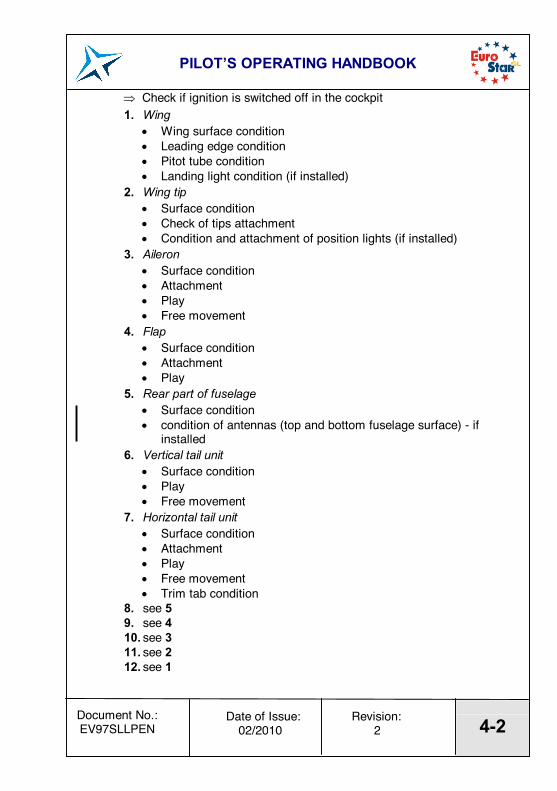
" Check if ignition is switched off in the cockpit 1. Wing
2. Wing tip ! Surface condition ! Check of tips attachment ! Condition and attachment of position lights (if installed)
3. Aileron ! Surface condition ! Attachment ! Play ! Free movement
4. Flap ! Surface condition ! Attachment ! Play
5. Rear part of fuselage ! Surface condition ! condition of antennas (top and bottom fuselage surface) - if
installed 6. Vertical tail unit
! Surface condition ! Play ! Free movement
7. Horizontal tail unit ! Surface condition ! Attachment ! Play ! Free movement ! Trim tab condition
8. see 5 9. see 4 10. see 3 11. see 2 12. see 1
02/2010 2
PILOTíS OPERATING HANDBOOK
4-3 Date of Issue:
02/2008 Revision: Document No.:
EV97SLLPEN
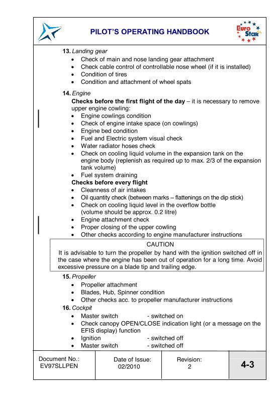
13. Landing gear ! Check of main and nose landing gear attachment ! Check cable control of controllable nose wheel (if it is installed) ! Condition of tires ! Condition and attachment of wheel spats
14. Engine Checks before the first flight of the day ñ it is necessary to remove upper engine cowling: ! Engine cowlings condition ! Check of engine intake space (on cowlings) ! Engine bed condition ! Fuel and Electric system visual check ! Water radiator hoses check ! Check on cooling liquid volume in the expansion tank on the
engine body (replenish as required up to max. 2/3 of the expansion tank volume)
! Fuel system draining Checks before every flight ! Cleanness of air intakes ! Oil quantity check (between marks ñ flattenings on the dip stick) ! Check on cooling liquid level in the overflow bottle
(volume should be approx. 0.2 litre) ! Engine attachment check ! Proper closing of the upper cowling ! Other checks according to engine manufacturer instructions
CAUTION It is advisable to turn the propeller by hand with the ignition switched off in the case where the engine has been out of operation for a long time. Avoid excessive pressure on a blade tip and trailing edge.
15. Propeller ! Propeller attachment ! Blades, Hub, Spinner condition ! Other checks acc. to propeller manufacturer instructions
16. Cockpit ! Master switch - switched on ! Check canopy OPEN/CLOSE indication light (or a message on the
EFIS display) function ! Ignition - switched off ! Master switch - switched off
check switch on Switch box and Master switch, then switch off!) ! Controls - visual check
- check for proper function - check of plays - check of flaps extension - check of free movement up to the stops
! Check for free items ! Check of safety belts condition and attachment ! Canopy - Condition of attachment,
cleanliness
02/2010
02/2010 2
PILOTíS OPERATING HANDBOOK
4-5 Date of Issue:
02/2008 Revision: Document No.:
EV97SLLPEN
4.4 Normal procedures
4.4.1 Before entering cockpit 1. Aeroplane surface - check of covers and caps 2. Cockpit - items inside the cockpit 3. Ignition - off 4. Master switch - off
4.4.2 After entering cockpit 1. Rudder pedals - free movement check 2. Parking brake handle - release brakes
(if installed) 3. Brakes - check of function 4. Control stick - free movement check 5. Trim - check of lever movement 6. Flaps - check of function 7. Engine controls
(throttle, choke) - check of movement 8. Fuel cock - shut off 9. Fuel gauge - fuel quantity check 10. Master switch - off 11. Circuit breakers - off 12. Ignition - off 13. Instruments, COMM, - condition check 14. Safety harness - check of integrity 15. Cockpit - condition and canopy lock function
PILOTíS OPERATING HANDBOOK
4-6 Date of Issue:
02/2008 Revision: Document No.:
EV97SLLPEN
4.4.3 Before engine starting and Engine starting 1. Fuel cock - open 2. Circuit breakers - switch on 3. Throttle - set for idling 4. Choke - according to engine temperature 5. Master switch - switch on 6. Propeller - set for take-off if in-flight variable prop
is installed 7. Electric fuel pump
(if installed) - switch on 8. Brakes - apply 9. Check of free area 10. Ignition box - switch to BOTH and activate starter 11. After starting - set throttle to idling 12. Oil pressure - within 10 sec. min. pressure 13. Choke - push to shut 14. AVIONICS - switch on 15. Engine warm - according to 4.4.4
CAUTION
The starter should be activated for a maximum of 10 sec., followed by a 2 min. pause for engine cooling. After starting the engine, adjust the throttle for smooth running between 2500-2750 rpm. Check the oil pressure, which should increase within 10 sec. Increase the engine speed after the oil pressure has reached 2 bars (29 psi) and is steady. To avoid shock loading, start the engine with the throttle lever set for idling or a maximum of 10 % opened, then wait 3 sec to reach constant engine speed before new acceleration. Only one magneto should be switched on (off) during ignition magneto check.
PILOTíS OPERATING HANDBOOK
4-7 Date of Issue:
02/2008 Revision: Document No.:
EV97SLLPEN
4.4.4 Engine warm up, Engine check Lock the main wheels by means of Scotch blocks before engine check. Initially warm up the engine to 2000 rpm then continue to 2500-2750 rpm till oil temperature reaches 50∞C (122 ∞F). The warm up period depends on ambient air temperature. Check both ignition circuits at 3850 rpm (4000 rpm for Rotax 912S). The engine speed drop during the time either magneto switched off should not overcome 300 rpm. The Max. engine speed drop difference between circuits R and L should be 115 rpm. Set max. power for verification of max. speed with given propeller and engine parameters (temperatures and pressures). Check acceleration from idling to max. power. If necessary, cool the engine at 3000 rpm before shutdown. Check the function of the pitch setting mechanism if in-flight variable prop is installed.
CAUTION The engine check should be performed with the aircraft heading upwind and not on loose terrain (the propeller may suck impurities which can damage the leading edges of blades).
4.4.5 Taxiing The recommended taxiing speed is 15 km/h (8 kts). The direction of taxiing can be controlled by the controllable nose wheel or by brakes. Hydraulic disc brakes are controlled by pedals on the rudder control.
PILOTíS OPERATING HANDBOOK
4-8 Date of Issue:
02/2008 Revision: Document No.:
EV97SLLPEN
4.4.6 Before take-off 1. Brakes - fully applied 2. Rudder pedals - check of free movement 3. Control stick - check of free movement 4. Trim - neutral position 5. Flaps - ÑTake-offì position 6. Propeller - set for take-off (fine pitch) if in-
flight variable prop is installed WARNING
Control overswitch of the constant speed propeller must be set to the ìMANUALî position before take-off, and propeller pitch must be set as above.
4.4.7 Take-off By gradually increasing power, set the aircraft into motion. The direction of take-off run can be controlled by the controllable nose wheel and by hydraulic brakes. Slightly pull the stick to unstick the nose wheel. The aircraft then takes-off at a speed above 75 km/h (40 kts). Slightly push the stick until the safety climb speed of 100 km/h (54 kts) has been reached. The Maximum Flap Extended speed is 125 km/h (67 kts). Refer to the par. 5.2.5 for optimum climbing speed.
WARNING The Take-off is prohibited if: ! The engine is running unsteadily ! The engine instruments values are beyond operational limits ! The engine choke is open ! The crosswind velocity exceeds permitted limits (see 5.3.3)
PILOTíS OPERATING HANDBOOK
4-9 Date of Issue:
02/2008 Revision: Document No.:
EV97SLLPEN
4.4.8 Climb 1. Throttle - Max. Take-off Power
(max. 5 min. 5750 rpm) - Max. Continuous Power (5500 rpm)
2. Speed - 115 km/h (62 kts, 72 mph) 3. Trim - adjust 4. Electric fuel pump
(if installed) - switch off 5. Instruments - CHT, Oil temp. and pressure within limits
CAUTION If the cylinder head temperature or oil temperature exceed their limits, reduce the climb angle to decrease airspeed and thus fulfil the limits.
4.4.9 Cruise The EV-97 Eurostar SL flight characteristics are very grateful within permitted limits of airspeeds, configurations and C/G range. The aircraft is very easy to both control and manoeuvre. For more details about horizontal flight regimes, refer to the Section 5 par. 5.3.1.
4.4.10 Descent 1. Throttle - idling 2. Speed - 110 km/h (60 kts, 68 mph) 3. Trim - as necessary 4. Instruments - within limits
CAUTION On the final approach and when descending from very high altitude, it is not advisable to reduce the engine throttle control lever to minimum. In such cases the engine becomes undercooled and a loss of power occurs. When descending, apply increased idle so that the engine instrument readings range are within the limits for normal use.
4.4.11 Check before landing 1. Fuel - fuel quantity check 2. Safety harness - tightened 3. Brakes - check function 4. Trim - adjust 5. Landing area check - runway area, base leg area
PILOTíS OPERATING HANDBOOK
4-10 Date of Issue:
02/2008 Revision: Document No.:
EV97SLLPEN
4.4.12 On base leg 1. Speed - 110 km/h (60 kts, 68 mph) 2. Flaps - extend to ÑTake-offì position 3. Propeller - in case of adjustable propeller set for
take-off (fine pitch) WARNING
Control overswitch of the constant speed propeller must be set to the ìMANUALî position before landing, and must stay in this position at landing, and propeller pitch must be set as above.
4. Trim - adjust 5. Parking brake - check for lever down
(if installed) CAUTION
Parking brake must be released (lever down) to prevent landing with braked wheels. 6. Electric fuel pump
(if installed) - switch on 7. Throttle - as necessary 8. Instruments - within limits
4.4.13 On final 1. Speed - 110 km/h (60 kts, 68 mph) 2. Flaps - ÑLandingì position 3. Trim - adjust 4. Throttle - as necessary 5. Propeller switch - in case of constant speed prop. check
setting toìMANUALî position and set fine pitch 6. Instruments - values within limits
4.4.14 Landing The airspeed during float is slowly reduced, so that the touch down speed is about 70 km/h (38 kts, 44 mph). Gradually pull the stick after touch down to hold the nose wheel up as long as possible. Push the control stick when the nose wheel touches the ground. The landing run can be shortened by braking.
4.4.15 Balked landing 1. Throttle - full 2. Engine speed - max.5800 rpm 3. Flaps - set to the ÑTake-offì position
at a speed of 100 km/h (54 kts, 62 mph)
PILOTíS OPERATING HANDBOOK
4-11 Date of Issue:
02/2008 Revision: Document No.:
EV97SLLPEN
4. Trim - as necessary 5. Flaps - retract at a height of 50 m (165 ft) 6. Trim - adjust 7. Engine speed - MTV, max.5500 rpm 8. Instruments - within limits 9. Climb - at 110 km/h (60 kts, 68 mph)
4.4.16 After landing 1. Engine speed - set as necessary for taxiing 2. Flaps - retracted and locked 3. Trim - neutral position
4.4.17 Engine shutdown 1. Engine speed - idling 2. Instruments - engine instruments within limits 3. COMM + intercom - switch off 4. Electric fuel pump
(if installed) - switch off 5. Ignition box - turn the key counterclockwise to switch off 6. Master switch - switch off 7. Fuel cock - shut off
CAUTION Rapid engine cooling should be avoided during operation. This happens above all during aircraft descent, taxiing, low engine rpm or at engine shutdown immediately after landing. Under normal conditions the engine temperatures stabilize during descent, taxiing and at values suitable to stop engine by switching the ignition off. If necessary, cool the engine at 2500 ñ 2750 rpm to stabilize the temperatures prior to engine shut down.
4.4.18 Flight in rain When flying in the rain, no additional steps are required. Aircraft qualities and performance are not substantially changed.
PILOTíS OPERATING HANDBOOK
5-0 Date of Issue:
02/2008 Revision: Document No.:
EV97SLLPEN
SECTION 5
5. PERFORMANCE 5.1 Introduction 5.2 Approved data 5.2.1 Airspeed indicator system calibration 5.2.2 Stall speeds 5.2.3 Take-off performance 5.2.4 Landing distances 5.2.5 Climb performance 5.3 Additional information 5.3.1 Cruise 5.3.2 Endurance 5.3.3 Balked landing climb 5.3.4 Effect on flight performance and characteristics 5.3.5 Demonstrated crosswind performance 5.3.6 Ceiling 5.3.7 Noise data
PILOTíS OPERATING HANDBOOK
5-1 Date of Issue:
02/2008 Revision: Document No.:
EV97SLLPEN
5.1 Introduction Section 5 provides approved data for airspeed calibration, stall speeds, take-off performance and non-approved additional information. The data in the charts has been computed from actual flight tests with the aircraft and engine in good conditions and using average piloting techniques. If not stated otherwise, the performance stated in this section is valid for the max. take-off weight and flight under ISA conditions. The performance given in this section is valid for aircraft with given engine and propeller types.
No distinctive warning. Aeroplane downward motion without pitching. Aeroplane is fully controllable. No excessive loss of altitude during recovery. *) MCP ñ maximum
continuous power 50 58
Stalling speed-
Stall Flaps setting Power setting Warning speed IAS
No distinctive warning. Aeroplane downward motion without pitching. Aeroplane is fully controllable. No excessive loss of altitude during recovery. *) MCP ñ maximum
continuous power 27 31
PILOTíS OPERATING HANDBOOK
5-4 Date of Issue:
02/2008 Revision: Document No.:
EV97SLLPEN
5.2.3 Take-off performance Take-off distances stated in the following table are valid at sea level and ambient temperature of 15 ∞C (59 ∞F).
RWY Take-off run distance
Take-off distance over 15 m (50 ft)
obstacle [m] [ft] [m] [ft]
CONCRETE 145 475 280 919 GRASS 155 509 300 984
5.2.4 Landing distances Landing distances stated in the following table are valid at sea level and ambient temperature of 15 ∞C (59 ∞F).
RWY Landing distance over 15 m (50 ft) obstacle
Landing run distance (braked)
[m] [ft] [m] [ft] CONCRETE 520 1706 210 689
GRASS 500 1640 200 656
PILOTíS OPERATING HANDBOOK
5-5 Date of Issue:
02/2008 Revision: Document No.:
EV97SLLPEN
5.2.5 Climb performance
EV-97 EUROSTAR Rate of climb
engine: Rotax 912 UL (80hp)propeller: V 230C (fixed, wooden, two blade, 18∞40')
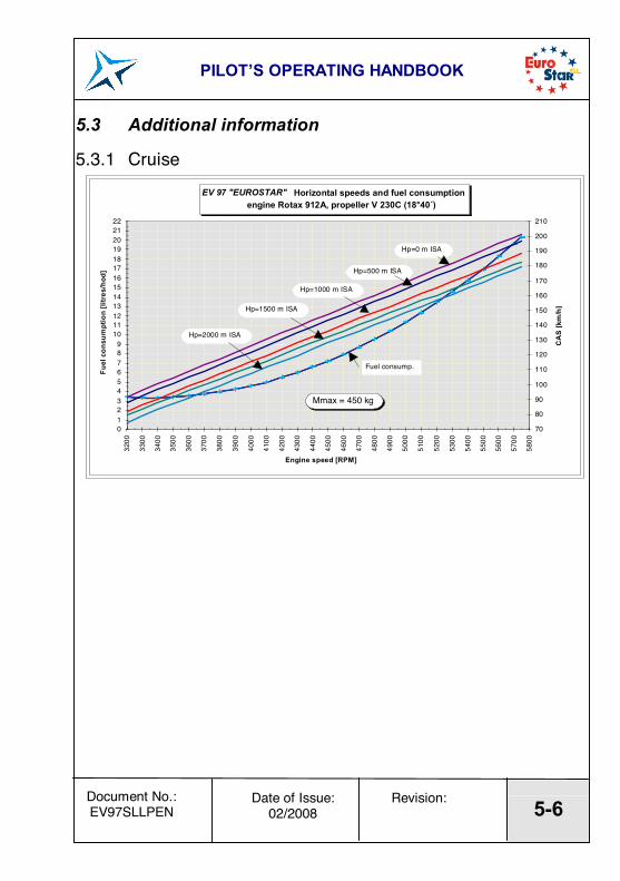
5.3.1 Cruise EV 97 "EUROSTAR" Horizontal speeds and fuel consumption
engine Rotax 912A, propeller V 230C (18∞40¥)
0123456789
10111213141516171819202122
3200
3300
3400
3500
3600
3700
3800
3900
4000
4100
4200
4300
4400
4500
4600
4700
4800
4900
5000
5100
5200
5300
5400
5500
5600
5700
5800
Engine speed [RPM]
Fuel
con
sum
ptio
n [li
tres
/hod
]
70
80
90
100
110
120
130
140
150
160
170
180
190
200
210
CA
S [k
m/h
]
Mmax = 450 kg
Fuel consump.
Hp=500 m ISA
Hp=1000 m ISA
Hp=1500 m ISA
Hp=2000 m ISA
Hp=0 m ISA
PILOTíS OPERATING HANDBOOK
5-7 Date of Issue:
02/2008 Revision: Document No.:
EV97SLLPEN
Horizontal speeds In the following tables state indicated airspeeds (IAS) and corresponding True air speeds (TAS) versus altitude, all for various engine speeds. Maximum
5.3.2 Endurance The following table states fuel consumptions, endurances and ranges for appropriate regimes. Fuel tank Volume = 65 litres 17,2 UsgalsFuel reserve = 11 litres 2,9 Usgals
EV-97 EUROSTAR Balked landing climbengine: Rotax 912 UL (80hp)
propeller: V 230C (fixed, wooden, two blade, 18∞40')
0,0
0,5
1,0
1,5
2,0
2,5
3,0
3,5
4,0
4,5
65 70 75 80 85 90 95 100 105 110 115 120 125 130
Airspeed IAS [km/h]
Rat
e of
clim
b [m
/s] flaps in ìTAKE-OFFî position
flaps in ÑLANDINGì position
PILOTíS OPERATING HANDBOOK
5-10 Date of Issue:
02/2008 Revision: Document No.:
EV97SLLPEN
5.3.4 Effect on flight performance and characteristics Flight performance and characteristics are not substantially affected by rain or accumulation of insects on the aeroplane surface.
5.3.5 Demonstrated crosswind performance Max. permitted cross wind velocity for take-off and landing ............................ 5 m/s 10 kts Max. permitted head wind velocity for take-off and landing .......................... 12 m/s 23 kts
5.3.6 Ceiling Service ceiling.....................................5000 m 16500 ft
5.3.7 Noise data 64.4 dB(A) - with Rotax 912 UL (80 hp) and V 230C prop 59.4 dB(A) - with Rotax 912 UL (80 hp) and Fiti Eco Competition prop 58.3 dB(A) - with Rotax 912 ULS (100 hp) and SR 2000 prop 59.2 dB(A) - with Rotax 912 ULS (100 hp) and Klassic 170/3/R prop. 59.1 dB(A) - with Rotax 912 ULS (100 hp) and Varia 170/2/R prop. .
PILOTíS OPERATING HANDBOOK
6-0 Date of Issue:
02/2008 Revision: Document No.:
EV97SLLPEN
SECTION 6
6. WEIGHT AND BALANCE 6.1 Introduction 6.2 Weight and balance record / Permitted payload range
PILOTíS OPERATING HANDBOOK
6-1 Date of Issue:
02/2008 Revision: Document No.:
EV97SLLPEN
6.1 Introduction This section contains the payload range within which the aircraft may be safely operated. Procedures for weighing the aircraft and the calculation method for establishing the permitted payload range are contained in the Technical Description, Operating and Maintenance Manual for the Ultra-light Aeroplane EV-97 Eurostar SL.
PILOTíS OPERATING HANDBOOK
6-2 Date of Issue:
02/2008 Revision: Document No.:
EV97SLLPEN
6.2 Weight and balance record / Permitted payload range
Sign
at.
A
ppro
ved
Dat
e
1/4
16 li
tre
4.2
US
gall
12 k
g 25
lbs
1/2
32 li
tre
8.5
US
galls
23 k
g 51
lbs
3/4
43 li
tre
11.4
US
galls
31 k
g 68
lbs
1 54
litr
e 14
.3 U
Sga
lls
39 k
g 86
lbs
1 65
litr
e 17
.2 U
Sga
lls
47 k
g 10
4 lb
s
max
. 15
kg
33
lbs
1/2
8 kg
17 lb
s
No
bagg
age
max
. 15
kg
33
lbs
1/2
8 kg
17 lb
s
No
bagg
age
max
. 15
kg
33
lbs
1/2
8 kg
17 lb
s
No
bagg
age
max
. 15
kg
33
lbs
1/2
8 kg
17 lb
s
No
bagg
age
FU
EL
LIN
G
Fuel
gau
ges
Fuel
vol
ume
Fuel
wei
ght
B A G G A G E
C.G
. po
sitio
n [%
MA
C]
Empt
y w
eigh
t [k
g] o
r [lb
s]
Perm
itted
cre
w w
eigh
t
[kg]
or [
lbs]
C
rew
wei
ght =
Max
.Tak
e-of
f wei
ght -
Em
pty
wei
ght -
Bag
gage
wei
ght ñ
Wei
ght o
f fue
l (0.
72 k
g/ltr
.)
Dat
e
CAU
TIO
N:
Incr
easi
ng o
f the
em
pty
wei
ght a
bove
303
kg
(668
lbs)
and
/or C
.G. p
ositio
n un
der 1
6 %
MAC
resu
lting
from
cus
tom
er re
quire
men
ts fo
r opt
iona
l equ
ipm
ent/i
nsta
llatio
ns, w
ill ca
use
dete
riora
tion
of th
e flig
ht c
hara
cter
istic
s.
Pe
rmitt
ed c
rew
wei
ght e
xcee
ding
cau
ses
serv
ice
life d
ecre
ase
of th
e ai
rpla
ne a
nd it
s
com
pone
nts.
PILOTíS OPERATING HANDBOOK
7-0 Date of Issue:
02/2008 Revision: Document No.:
EV97SLLPEN
SECTION 7
7. AEROPLANE AND SYSTEMS DESCRIPTION 7.1 Introduction 7.2 Airframe 7.2.1 Fuselage 7.2.2 Wing 7.2.3 Horizontal tail unit (HTU) 7.2.4 Vertical tail unit (VTU) 7.3 Controls in the cockpit 7.4 Instrument panel 7.5 Landing gear 7.6 Seats and safety harness 7.7 Baggage compartment 7.8 Canopy 7.9 Powerplant 7.10 Fuel system 7.11 Electrical system 7.12 Pitot and static pressure systems 7.13 Miscellaneous equipment 7.14 Avionics
PILOTíS OPERATING HANDBOOK
7-1 Date of Issue:
02/2008 Revision: Document No.:
EV97SLLPEN
7.1 Introduction This section provides description and operation of the aircraft and its systems. Refer to section 9, Supplements, for details of optional systems and equipment.
7.2 Airframe The EV-97 Eurostar SL airframe is of semimonocoque, metal composite construction, formed with metal reinforcements, bulkheads and a duralumin cover.
7.2.1 Fuselage The fuselage has a semimonocoque construction formed with reinforcements and duralumin covers. The fuselage cross-section is rectangular in the lower section and elliptical in the upper one. The tail fin is an integral part of the fuselage. In the middle section of the fuselage there is a two-man cockpit which is accessible by unfolding the one-part perspex overlap canopy. The engine section in the nose is separated from the crew by a firewall to which the engine bed is attached.
7.2.2 Wing The rectangular wing is a monospar construction with an auxiliary spar for the ailerons and flaps attachments. All the elements are riveted together. At the ends of the wings fibre glass wing tips are riveted. The wing can be equipped with a folding mechanism for a convenient storing in the hangar.
7.2.3 Horizontal tail unit (HTU) The rectangular HTU consists of a stabiliser and elevator with a trim tab. The semimonocoque construction of the HTU consists of duralumin ribs, spar and cover.
PILOTíS OPERATING HANDBOOK
7-2 Date of Issue:
02/2008 Revision: Document No.:
EV97SLLPEN
7.2.4 Vertical tail unit (VTU) The trapezoidal fin section of the VTU is mounted to the rear section of the fuselage. The rudder is attached on the fin by two hinges. The frame of the VTU is composed of a metal sheet spar and a duralumin cover.
PILOTíS OPERATING HANDBOOK
7-3 Date of Issue:
02/2008 Revision: Document No.:
EV97SLLPEN
7.3 Controls in the cockpit
PILOTíS OPERATING HANDBOOK
7-4 Date of Issue:
02/2008 Revision: Document No.:
EV97SLLPEN
7.4 Instrument panel The aeroplane EV-97 Eurostar SL, S/N XXXXXXXXXX: is equipped with the following instrument panel:
PILOTíS OPERATING HANDBOOK
7-5 Date of Issue:
02/2008 Revision: Document No.:
EV97SLLPEN
7.5 Landing gear The plane has fixed landing gear with a controllable nose wheel. The main landing gear legs are composed of a composite spring. The wheels on both landing gear legs are equipped with 14 x 4 tyres with hydraulic disc brakes that are controlled by foot pedals on the main rudder pedals. The nose landing gear leg is welded from steel tubes and its suspension is made from rubber rope. The nose wheel steering system is connected to the rudder control. The wheels may be equipped with aerodynamic, fiberglass covers.
7.6 Seats and safety harness The plane has two side-by-side seats which are fixed, unadjustable and thinly upholstered. Each seat is equipped with four point safety belts attached to the side of bulkhead behind the baggage compartment and alongside the seats.
7.7 Baggage compartment The baggage compartment is located behind the seats. Maximum baggage weight is stated on the placard located near the baggage compartment
PILOTíS OPERATING HANDBOOK
7-6 Date of Issue:
02/2008 Revision: Document No.:
EV97SLLPEN
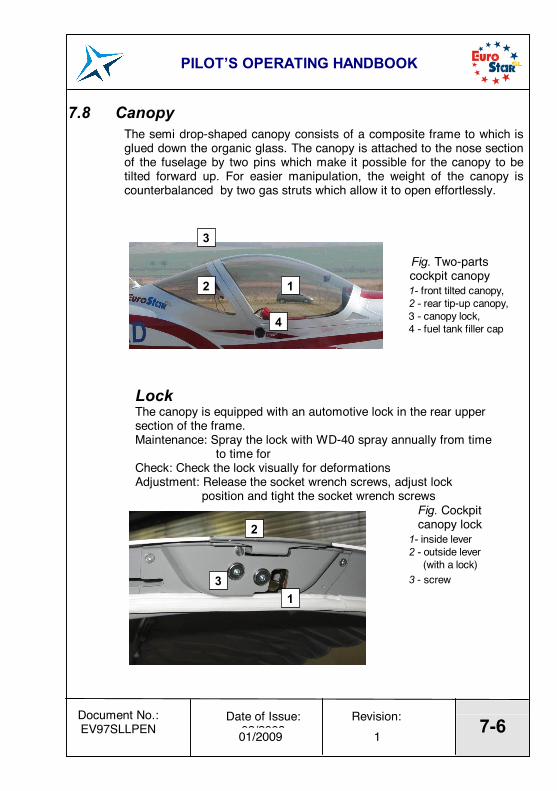
7.8 Canopy The semi drop-shaped canopy consists of a composite frame to which is glued down the organic glass. The canopy is attached to the nose section of the fuselage by two pins which make it possible for the canopy to be tilted forward up. For easier manipulation, the weight of the canopy is counterbalanced by two gas struts which allow it to open effortlessly.
Fig. Two-parts cockpit canopy 1- front tilted canopy, 2 - rear tip-up canopy, 3 - canopy lock, 4 - fuel tank filler cap
Lock The canopy is equipped with an automotive lock in the rear upper section of the frame. Maintenance: Spray the lock with WD-40 spray annually from time to time for Check: Check the lock visually for deformations Adjustment: Release the socket wrench screws, adjust lock position and tight the socket wrench screws
Fig. Cockpit canopy lock
1- inside lever 2 - outside lever (with a lock) 3 - screw
1 2
3
4
1
2
3
01/2009 1
PILOTíS OPERATING HANDBOOK
7-7 Date of Issue:
02/2008 Revision: Document No.:
EV97SLLPEN
7.9 Powerplant The standard powerplant of the EV-97 Eurostar SL is the ROTAX 912UL (80 hp) engine. The ROTAX 912ULS (100 hp) may be installed as option. Rotax 912 is 4-stroke, 4 cylinder horizontally opposed, spark ignition engine with one central camshaft-push-rod-OHV. Liquid cooled cylinder heads, ram air cooled cylinders. Dry sump forced lubrication. Dual breakerless capacitor discharge ignition. The engine is fitted with an electric starter, AC generator and mechanical fuel pump. Prop drive via reduction gear with integrated shock absorber. The two blade, fixed, propeller WODCOMP composite 3 bladed ground adjustable is installed as standard on the ROTAX 912UL engine.
PILOTíS OPERATING HANDBOOK
7-8 Date of Issue:
02/2008 Revision: Document No.:
EV97SLLPEN
7.9.1 Oil Thermostat The aircraft can be optionally equipped with an oil thermostat installed in the engine compartment ñ see pictures. Installation of oil thermostat reduces heating time of the cold engine. Oil flows from the tank through the oil pump into the engine and only after sufficient heating thermostat switches - on and oil starts to flow through the oil cooler. In addition, the thermostat helps to keep the oil temperature in the recommended operating limits, especially during descent with reduced engine power when the engine could be overcooled. The thermostat switches - on approximately 80 ∞ C.
Oil Thermostat
3 03/2011
PILOTíS OPERATING HANDBOOK
7-9 Date of Issue:
02/2008 Revision: Document No.:
EV97SLLPEN
7.10 Fuel system The fuel system consists of a 65 litre (17.2 USgals) tank, a fuel cock, a filter and a fuel pump on the engine. The tank is positioned in the separate space behind the seats, has a drain pocket and a drain valve. The outlet is situated below the fuselage. Fuel quantity is indicated by a fuel-sight gauge or by an electric float fuel gauge. The electric fuel gauge indicates the relative quantity of fuel in the tank (corresponding quantity in litres is shown in the table 6.2 and on placard ìLOAD LIMITSî in the cockpit).
7.11 Electrical system The electric system is single-wire type with the negative connected to the chassis. Both the single-phase generator integrated to the engine and the 12V/16Ah maintenanceless battery located on the firewall serve as power sources. The system is protected by the main circuit breaker (ACCU) positioned on the instrument panel. The circuits of the particular sections are each guarded separately by circuit breakers. The engine dual ignition is a separate part of the electric system. Each ignition circuit is has its own position on the ignition box to allow ignition check and position BOTH for normal operation. Piper type external power socket can be installed optionally. Socket is located on the right side of the fuselage, behind the firewall.
03/2011 3
PILOTíS OPERATING HANDBOOK
7-10 Date of Issue:
02/2008 Revision: Document No.:
EV97SLLPEN
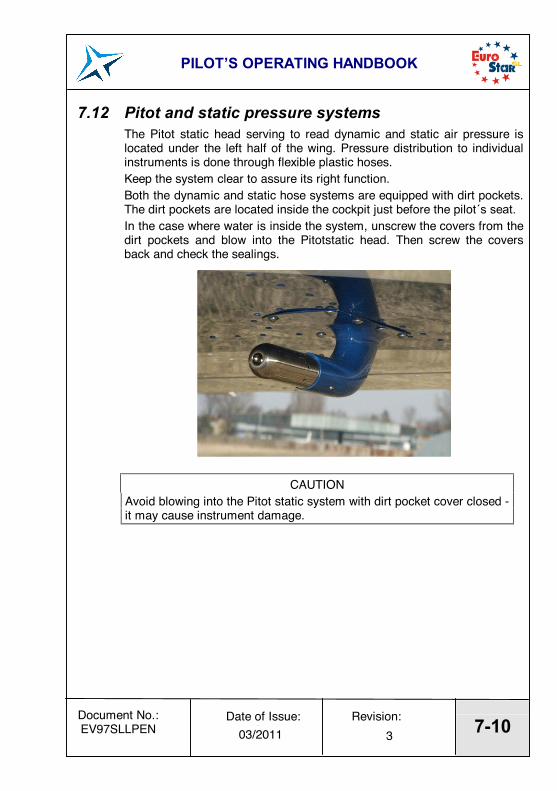
7.12 Pitot and static pressure systems The Pitot static head serving to read dynamic and static air pressure is located under the left half of the wing. Pressure distribution to individual instruments is done through flexible plastic hoses. Keep the system clear to assure its right function. Both the dynamic and static hose systems are equipped with dirt pockets. The dirt pockets are located inside the cockpit just before the pilot¥s seat. In the case where water is inside the system, unscrew the covers from the dirt pockets and blow into the Pitotstatic head. Then screw the covers back and check the sealings.
CAUTION Avoid blowing into the Pitot static system with dirt pocket cover closed - it may cause instrument damage.
03/2011 3
PILOTíS OPERATING HANDBOOK
7-11 Date of Issue:
02/2008 Revision: Document No.:
EV97SLLPEN
7.13 Miscellaneous equipment Besides the instruments stated in par. 0, the EV-97 Eurostar SL aeroplane, S/N XXXXXXX: is fitted with the following equipment:
! vybavenÌ dle zak·zkovÈho listu
03/2011 3
PILOTíS OPERATING HANDBOOK
7-12 Date of Issue:
02/2008 Revision: Document No.:
EV97SLLPEN
7.14 Avionics ! Flight instruments:
(standard equipment) 1 Airspeed indicator ...................... LUN 1106-8 1 Altimeter .................................... BG-3E 1 Compass ................................... C 2300 1 Variometer ................................. LUN 1147.15-8 The EV-97 Eurostar SL, S/N XXXXXXX is additionally equipped with the following instruments:
NOTE
Refer to the documentation supplied with ìnon-standard,ì instruments for operating instructions.
! Engine instruments The following powerplant instruments are installed in the EV-97 Eurostar SL aeroplane, S/N xxxx xxxx: 1 Engine RPM indicator ................................................ Mitchell 1 Engine cylinder head temperature (CHT) indicator...... Mitchell 1 Oil temperature indicator............................................ Mitchell 1 Oil pressure indicator ................................................. Mitchell
The EV-97 Eurostar SL, S/N XXXXXXXX is additionally equipped with the following engine instruments: 1 Electric Float Fuel Gauge........... SW 13.803
03/2011 3
PILOTíS OPERATING HANDBOOK
8-0 Date of Issue:
02/2008 Revision: Document No.:
EV97SLLPEN
SECTION 8
8. Aeroplane handling, servicing and maintenance 8.1 Introduction 8.2 Aircraft inspection periods 8.3 Aircraft alterations or repairs 8.4 Ground handling / Road transport 8.4.1 Towing 8.4.2 Parking 8.4.3 Mooring 8.4.4 Jacking 8.4.5 Levelling 8.4.6 Road transport 8.5 Cleaning and care
PILOTíS OPERATING HANDBOOK
8-1 Date of Issue:
02/2008 Revision: Document No.:
EV97SLLPEN
8.1 Introduction This section contains factory-recommended procedures for proper ground handling and servicing of the aeroplane. It also identifies certain inspection and maintenance requirements which must be followed if the aeroplane is to retain that new-plane performance and dependability. It is wise to follow a planned schedule of lubrication and preventive maintenance based on climatic and flying conditions encountered. This should be done according to the Technical Description, Operating and Maintenance Manual for Ultra-light Aeroplane EV-97 Eurostar SL
8.2 Aircraft inspection periods Periods of overall checks and contingent maintenance depends on the condition of the operation and on overall condition of the aeroplane. The manufacturer recommends that maintenance checks and periodic inspections should be carried out in the following periods, at least: a) after the first 25 ± 2 flight hours b) after every 50 ± 3 flight hours c) after every 100 ± 5 flight hours or at least annual inspection.
Every other annual inspection should be performed by the manufacturer.
Refer to the Rotax 912 Operator¥s Manual for engine maintenance. Maintain the prop according to its manual. Refer to the Technical Description, Operating and Maintenance Manual for the Ultra-light Aeroplane EV-97 Eurostar SL for more details about maintenance.
8.3 Aircraft alterations or repairs It is essential that the responsible airworthiness authority and the aircraft manufacturer be contacted prior to any alternations to the aircraft to ensure that the airworthiness of the aircraft is not violated. If the aircraft weight is affected by that alternation, a new weighing is necessary to take note of the new empty weight. Then the Weight and balance record / Permitted payload range 6.2 and up-date the placard ìLoad Limits,ì have to be filled in.
Refer to the Technical Description, Operating and Maintenance Manual for Ultra-light Aeroplane EV-97 Eurostar SL for aeroplane repairs.
PILOTíS OPERATING HANDBOOK
8-2 Date of Issue:
02/2008 Revision: Document No.:
EV97SLLPEN
8.4 Ground handling / Road transport
8.4.1 Towing It is easy to tow the aircraft a short distance by holding the prop blade at the root since the empty weight of this aeroplane is relatively low. Suitable surfaces to hold the aeroplane airframe are the rear part of the fuselage before the fin and wing roots. A tow bar may be used to tow the aeroplane a long distance.
CAUTION Avoid excessive pressure at the aeroplane airframe - especially at the wing tips, elevator, rudder, trim etc.
CAUTION Handle the propeller by holding the blade root - never blade tip! If starting the engine manually - always handle the propeller on a blade surface i.e. do not hold only an edge.
8.4.2 Parking It is advisable to park the aeroplane inside a hangar or alternatively inside any other proof space (garage) with stable temperature, good ventilation, low humidity and dust-free environment. It is necessary to moor the aeroplane when it is parked outside a hangar. Also when parking for a long time, cover the cockpit canopy, possibly the whole aeroplane by means of a suitable tarpaulin.
PILOTíS OPERATING HANDBOOK
8-3 Date of Issue:
02/2008 Revision: Document No.:
EV97SLLPEN
8.4.3 Mooring If the aircraft is parked outside a hanger then it requires to be moored securely. The mooring is necessary to protect the aeroplane against possible damage caused by wind and gusts. For this reason the aircraft is equipped with mooring eyes located on the lower surfaces of the wings. Mooring procedure: 1. Check: Fuel cock shut off, Circuit breakers and Master switch
switched off, Switch box switched off. 2. Block the control stick up e.g. by means of safety harness or connect
the control stick with rudder pedals by means of a suitable rope. 3. Shut all the ventilation windows. 4. Close and lock cockpit. 5. Moor the aircraft to the ground by means of a mooring rope passed
through the mooring eyes located on the lower surfaces of the wi ngs. It is also necessary to moor the nose wheel landing gear and the tail skid to the ground.
NOTE In the case of long term parking it is advisable to cover the cockpit canopy, or possibly the whole aircraft, by means of a suitable tarpaulin attached to the airframe.
PILOTíS OPERATING HANDBOOK
8-4 Date of Issue:
02/2008 Revision: Document No.:
EV97SLLPEN
8.4.4 Jacking Because the empty weight of this aircraft is relatively low, two people can lift the aircraft easily. First of all prepare two suitable supports to support the aircraft. It is possible to lift the aircraft by handling the following parts: ! Press on the rear part of the fuselage, just before the fin, to lift the
front of the aircraft. Then support the weight under the firewall. ! To jack the rear part of the aircraft, handle the fuselage near the
auxiliary tail skid, lift it upward and support. ! To lift the wings, push from underneath the wings only at the main
spar. Avoid lifting the wings by means of handling the wing tips.
8.4.5 Levelling Refer to the Technical Description, Operating and Maintenance Manual for the Ultra-light Aeroplane EV-97 Eurostar SL for more details about levelling.
8.4.6 Road transport The aircraft may be transported after its loading by a suitable car trailer. It is necessary to dismantle the wings before road transport. The aircraft and dismantled wings should be fastened down securely to ensure these parts against possible damage.
PILOTíS OPERATING HANDBOOK
8-5 Date of Issue:
02/2008 Revision: Document No.:
EV97SLLPEN
8.5 Cleaning and care Use efficient cleaning detergents to clean the aircraft surface. Oil spots on the aircraft surface (except the canopy!) may be cleaned with petrol. The canopy may only be cleaned by washing it with a sufficient quantity of lukewarm water and an adequate quantity of a detergents. Use either a soft, clean cloth sponge or deerskin. Then use suitable polishers to clean the canopy.
CAUTION Never clean the canopy under ìdryì conditions and never use petrol or chemical solvents! Upholstery and covers can be removed from the cockpit, brushed and eventually washed in lukewarm water with an adequate quantity of detergents. Dry the upholstery thoroughly before insertion into the cockpit.
CAUTION In the case of long term parking, cover the canopy to protect the cockpit interior from direct sunshine.
PILOTíS OPERATING HANDBOOK
9-0 Date of Issue:
02/2008 Revision: Document No.:
EV97SLLPEN
SECTION 9
9. Supplements 9.1 Introduction 9.2 List of inserted supplements 9.3 Supplements inserted
PILOTíS OPERATING HANDBOOK
9-1 Date of Issue:
02/2008 Revision: Document No.:
EV97SLLPEN
9.1 Introduction This section contains the appropriate supplements necessary to safely and efficiently operate the aircraft when equipped with various optional systems and equipment not provided with the standard aeroplane.
9.2 List of inserted supplements Date Doc.No. Title of inserted supplement