Introduction Anritsu introduces the first fully integrated Passive Intermodulation (PIM) Analyzer plus Cable and Antenna Analyzer (Option 331) suitable for commissioning and maintaining global wireless networks. This high performance, battery operated unit allows operators to fully characterize infrastructure quality by measuring Return Loss, VSWR, Cable Loss, Passive Intermodulation, Distance-to-Fault, and Distance-to-PIM with a single test instrument.
Passive Intermodulation (PIM) Analyzer Highlights • PIM vs. Time, Swept PIM, Noise Floor, Distance-to-PIM• 3rd, 5th, and 7th order intermodulation products• 2nd order intermodulation products with Option 902• Test Power: 20 dBm to 46 dBm• Residual PIM: –125 dBm typical
Cable and Antenna Analyzer Highlights (Option 331) • Measurements: RL, VSWR, Cable Loss, DTF, Phase• Frequency range: 2 MHz to 3 GHz• Sweep Speed: 1 ms/data point typical• Calibration: OSL and FlexCal™
Capabilities and Functional Highlights • Integrated solution• Battery operated: >3.0 hour run time• Display: 8.4 in (213 mm) daylight viewable• IP54 rated for dust and water spray• MIL-STD-810G drop test rated• Stainless steel lifting rings• Padded soft case for extra protection• Easy-to-use, menu driven user interface• Quick Name Matrix simplifies naming in the field• GPS tag measurements (Option 31)• High Accuracy Power Meter (Option 19)
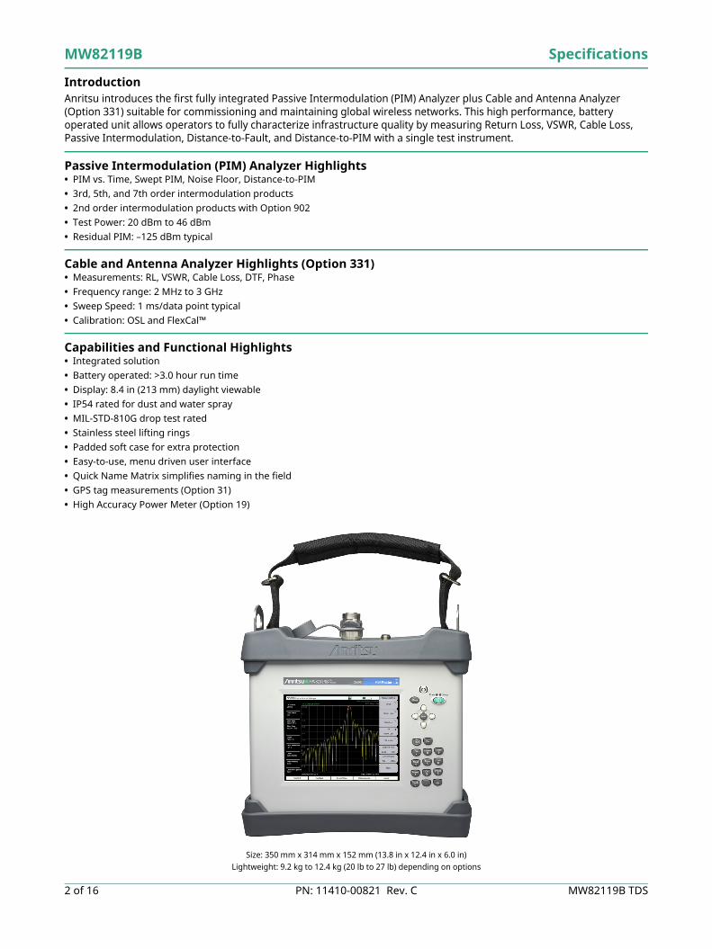
Size: 350 mm x 314 mm x 152 mm (13.8 in x 12.4 in x 6.0 in)Lightweight: 9.2 kg to 12.4 kg (20 lb to 27 lb) depending on options
Definitions All specifications and characteristics apply under the following conditions, unless otherwise stated: Warm-Up Time After 10 minutes of warm-up time, where the instrument is left in the on state.
Temperature Range Over the 23 °C ±5 °C temperature range.Typical Performance Typical specifications in parenthesis () describe performance that will be met by a minimum of 80% of all
products. They do not include guard bands and are not warranted.Typical specifications that are not in parenthesis are not tested and not warranted. They are generally representative of the nominal characteristic performance.
Uncertainty A coverage factor of K=2 is applied to the measurement uncertainties.Calibration Cycle Recommended calibration cycle is 12 months.
All specifications subject to change without notice. For the most current data sheet, please visit the Anritsu web site: www.anritsu.com
PIM Master ConnectorsPIM Test Port 7/16 DIN, female, 50 Ω
Dual USB Type A 2x Type A (connect USB Flash Drive and USB Power Sensor)USB Mini-B 1x Mini-B (connect to PC for data transfer)
GPS SMA, female (with GPS option only)External Power 2.1 mm x 5.5 mm barrel connector, 12 VDC to 15 VDC, < 5.0 A
PIM Test Port Damage Level +10 dBm (10 mW) continuous, (PIM Rx band)+35 dBm (3 W) continuous, (PIM Tx band)*
IM2 In Test Port Type N, Female, 50 Ω (Option 902 only)IM2 In Test Port Damage Level +10 dBm (10 mW) continuous, (IM2 Rx band)
VNA Test Port Type N, female, 50 Ω (Option 331)VNA Test Port Damage Level 40 dBm continuous
* Able to survive full reflection of 2 X 46 dBm PIM test tones generated by the MW82119B.
DisplaySize 213 mm (8.4 in) touch screen
Resolution 800 x 600
BatteryType Li-Ion
Battery Operation 3.0 hours, typicalCharging Limits While charging, battery must be 0 °C to +45 °C, Relative Humidity ≤ 80 %
PowerAC/DC Adapter Input: 100VAC to 240 VAC, 50/60 Hz
Output: 12 VDC
Electromagnetic CompatibilityEuropean Union CE Mark
EMC Directive 2004/108/ECEmissions EN 55011:2009 +A1:2010 Group 1 Class AImmunity EN 61000-4-2/3/4/5/6/11
Australia and New Zealand RSMSouth Korea KCC
SafetyLow Voltage Directive 2006/95/EC
Product Safety EN 61010-1:2010, IEC 60950-1(when used with Anritsu Company supplied Power Supply)
EnvironmentalOperating Temperature –10 °C to 55 °C
Storage Temperature –51 °C to 71 °CMaximum Relative Humidity 95 %, Non-condensing
Ingress Protection (IP) IP54, IP67 when enclosed in optional transit caseMechanical Shock MIL-PRF-28800F Class 2, (30G half-sine, 6 shocks each axis, while operating)
Transit Drop MIL-STD-810G, Method 516.6, Procedure IV, 122 cm (48 in) drop height, each face, edge and corner, (26 drops total), in soft carry case.
Altitude 4600 meters (15092 ft), operating and non-operating
ESDPIM Test Port Connector Center Pin Withstands up to ±15 kV
VNA RF Out Connector Center Pin Withstands up to ±15 kV
Size and WeightSize 350 mm x 314 mm x 152 mm (13.8 in x 12.4 in x 6.0 in)
Weight 9.2 kg to 12.4 kg (20 lb to 27 lb), varies by frequency option
Specifications MW82119B
MW82119B TDS PN: 11410-00821 Rev. C 5 of 16
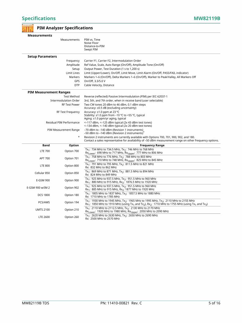
PIM Analyzer Specifications
MeasurementsMeasurements PIM vs. Time
Noise Floor Distance-to-PIM Swept PIM
Setup ParametersFrequency Carrier F1, Carrier F2, Intermodulation OrderAmplitude Ref Value, Scale, Auto Range (On/Off), Amplitude Tone (On/Off)
Setup Output Power, Test Duration (1 s to 1,200 s)Limit Lines Limit (Upper/Lower), On/Off, Limit Move, Limit Alarm (On/Off, PASS/FAIL indicator)
Markers Markers 1–6 (On/Off), Delta Markers 1–6 (On/Off), Marker to Peak/Valley, All Markers OffGPS On/Off, 3.3/5.0 VDTP Cable Velocity, Distance
PIM Measurement Range –70 dBm to –140 dBm (Revision 1 instruments)–50 dBm to –140 dBm (Revision 2 instruments)*
* Revision 2 instruments are currently available with Options 700, 701, 900, 902, and 180.Contact a sales representative for availability of –50 dBm measurement range on other frequency options.
Band Option Frequency Range
LTE 700 Option 700 Tx1: 734 MHz to 734.5 MHz, Tx2: 746 MHz to 768 MHz RxLower: 698 MHz to 717 MHz, RxUpper: 777 MHz to 806 MHz
APT 700 Option 701 Tx1: 758 MHz to 776 MHz, Tx2: 788 MHz to 803 MHz RxLower: 710 MHz to 748 MHz, RxUpper: 825 MHz to 845 MHz
LTE 800 Option 800 Tx1: 791 MHz to 795 MHz, Tx2: 811.5 MHz to 821 MHzRx: 832 MHz to 862 MHz
Cellular 850 Option 850 Tx1: 869 MHz to 871 MHz, Tx2: 881.5 MHz to 894 MHzRx: 824 MHz to 849 MHz
E-GSM 900 Option 900 Tx1: 925 MHz to 937.5 MHz, Tx2: 951.5 MHz to 960 MHz Rx1: 880 MHz to 915 MHz, Rx2: 1876.5 MHz to 1920 MHz
E-GSM 900 w/IM 2 Option 902 Tx1: 925 MHz to 937.5 MHz, Tx2: 951.5 MHz to 960 MHz Rx1: 885 MHz to 915 MHz, Rx2: 1877 MHz to 1920 MHz
DCS 1800 Option 180 Tx1: 1805 MHz to 1837 MHz, Tx2: 1857.5 MHz to 1880 MHz Rx: 1710 MHz to 1785 MHz
PCS/AWS Option 194 Tx1: 1930 MHz to 1945 MHz, Tx2: 1965 MHz to 1995 MHz, Tx3: 2110 MHz to 2155 MHz Rx1: 1850 MHz to 1910 MHz (using Tx1 and Tx2), Rx2: 1710 MHz to 1755 MHz (using Tx1 and Tx3)
UMTS 2100 Option 210 Tx1: 2110 MHz to 2112.5 MHz, Tx2: 2130 MHz to 2170 MHz RxLower: 1920 MHz to 1980 MHz, RxUpper: 2050 MHz to 2090 MHz
LTE 2600 Option 260 Tx1: 2620 MHz to 2630 MHz, Tx2: 2650 MHz to 2690 MHz Rx: 2500 MHz to 2570 MHz
MW82119B Specifications
6 of 16 PN: 11410-00821 Rev. C MW82119B TDS
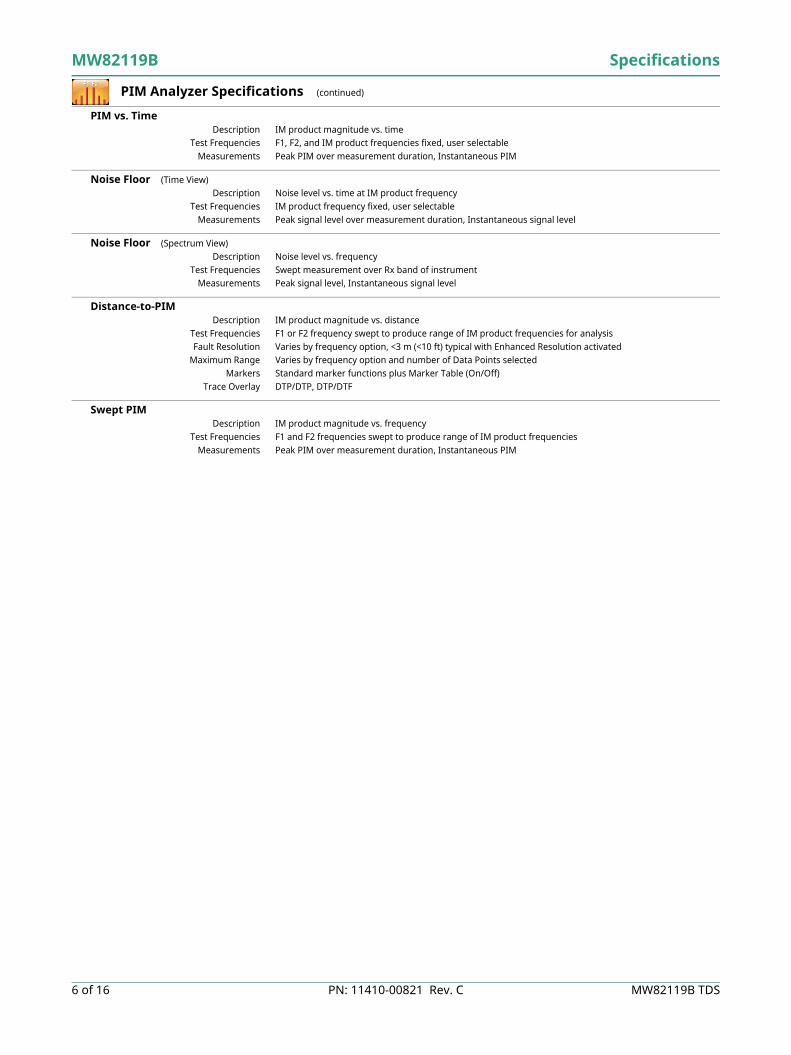
PIM Analyzer Specifications (continued)
PIM vs. TimeDescription IM product magnitude vs. time
Test Frequencies F1, F2, and IM product frequencies fixed, user selectableMeasurements Peak PIM over measurement duration, Instantaneous PIM
Noise Floor (Time View)Description Noise level vs. time at IM product frequency
Test Frequencies IM product frequency fixed, user selectableMeasurements Peak signal level over measurement duration, Instantaneous signal level
Noise Floor (Spectrum View)Description Noise level vs. frequency
Test Frequencies Swept measurement over Rx band of instrumentMeasurements Peak signal level, Instantaneous signal level
Distance-to-PIMDescription IM product magnitude vs. distance
Test Frequencies F1 or F2 frequency swept to produce range of IM product frequencies for analysisFault Resolution Varies by frequency option, <3 m (<10 ft) typical with Enhanced Resolution activated
Maximum Range Varies by frequency option and number of Data Points selectedMarkers Standard marker functions plus Marker Table (On/Off)
Trace Overlay DTP/DTP, DTP/DTF
Swept PIMDescription IM product magnitude vs. frequency
Test Frequencies F1 and F2 frequencies swept to produce range of IM product frequenciesMeasurements Peak PIM over measurement duration, Instantaneous PIM
GPS Receiver Option (Option 31) (Antenna sold separately)
Setup On/Off, Antenna Voltage 3.3/5.0 V, GPS InfoGPS Time/Location Indicator Time, Latitude, Longitude and Altitude on display
Time, Latitude, Longitude and Altitude with trace storageConnector SMA, Female
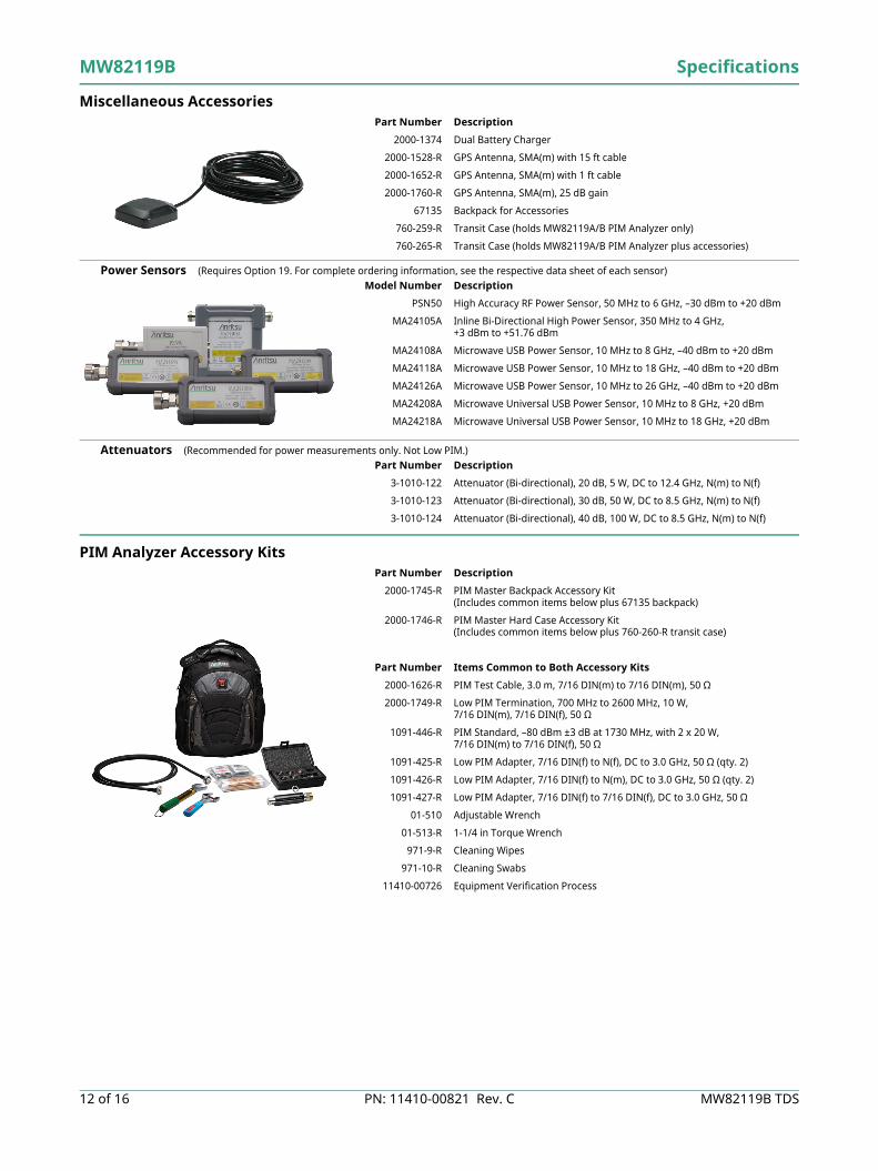
High Accuracy Power Meter (Requires external USB power sensor, sold separately)
Amplitude Maximum, Minimum, Offset, Relative On/Off, Units, Auto ScaleAverage # of Running Averages, Max HoldZero/Cal Zero On/Off, Cal Factor (Center Frequency, Signal Standard)
Limits Limit On/Off, Limit Upper/Lower
Power Sensor Model PSN50a MA24105A MA24108A/18A/26A MA24208A/18Af Description High Accuracy
RF Power SensorInline High Power Sensor
Microwave USB Power Sensor
Microwave Universal USB Power Sensor
Frequency Range 50 MHz to 6 GHz 350 MHz to 4 GHz 10 MHz to 8/18/26 GHz 10 MHz to 8/18 GHzConnector Type N(m), 50 Ω Type N(f), 50 Ω Type N(m), 50 Ω
(8/18 GHz)Type K(m), 50 Ω(26 GHz)
Type N(m), 50 Ω
Dynamic Range –30 dBm to +20 dBm(0.001 mW to 100 mW)
+3 dBm to +51.76 dBm(2 mW to 150 W)
–40 dBm to +20 dBm(0.1 µW to 100 mW)
–60 dBm to +20 dBm(1 nW to 100 mW)
Measurand True-RMS True-RMS True-RMS, Slot Power, Burst Average Power
Notes: a. The PSN50 sensor can be used only with Anritsu handheld instruments with Option 19. The MA241xxA sensors work with Anritsu instruments with Option 19 and also can be used separately with a PC.
b. Total RSS measurement uncertainty (0 ºC to 50 ºC) for power measurements of a CW signal greater than –20 dBm with zero mismatch errors.
c. Expanded uncertainty with K=2 for power measurements of a CW signal greater than +20 dBm with a matched load. Measurement results referenced to the input side of the sensor.
d. Expanded uncertainty with K=2 for power measurements of a CW signal greater than –20 dBm with zero mismatch errors.e. Power uncertainty expressed with two sigma confidence level for CW measurement after zero operation. Includes
calibration factor and linearity over temperature uncertainties, but not the effects of mismatch, zero set and drift, or noise.
f. MA24208A and MA24218A require sensor firmware v1.40 or higher.
1
10
100
-40 -35 -30 -25 -20 -15 -10 -5 0
Phas
e U
ncer
tain
ty (d
egre
es)
Return Loss (dB)
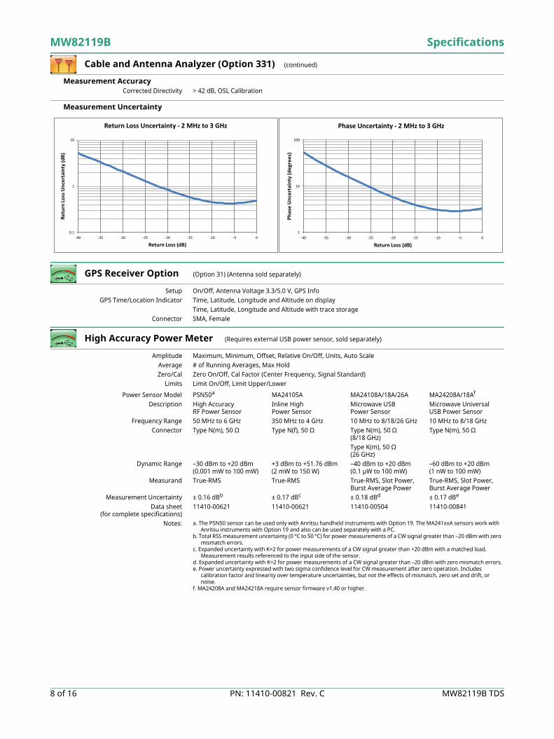
Phase Uncertainty - 2 MHz to 3 GHz
0.1
1
10
-40 -35 -30 -25 -20 -15 -10 -5 0
Retu
rn Lo
ss U
ncer
tain
ty (d
B)
Return Loss (dB)
Return Loss Uncertainty - 2 MHz to 3 GHz
Specifications MW82119B
MW82119B TDS PN: 11410-00821 Rev. C 9 of 16
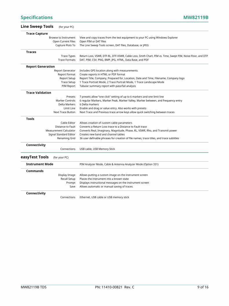
Line Sweep Tools (for your PC)
Trace CaptureBrowse to Instrument View and copy traces from the test equipment to your PC using Windows Explorer
Open Current Files Open PIM or DAT filesCapture Plots To The Line Sweep Tools screen, DAT files, Database, or JPEG
TracesTrace Types Return Loss, VSWR, DTF-RL, DTF-VSWR, Cable Loss, Smith Chart, PIM vs. Time, Swept PIM, Noise Floor, and DTP
Trace Formats DAT, PIM, CSV, PNG, BMP, JPG, HTML, Data Base, and PDF
Report GenerationReport Generator Includes GPS location along with measurements
Report Format Create reports in HTML or PDF formatReport Setup Report Title, Company, Prepared for, Location, Date and Time, Filename, Company logo
Trace ValidationPresets 7 presets allow “one click” setting of up to 6 markers and one limit line
Marker Controls 6 regular Markers, Marker Peak, Marker Valley, Marker between, and frequency entryDelta Markers 6 Delta markers
Limit Line Enable and drag or value entry. Also works with presetsNext Trace Button Next Trace and Previous trace arrow keys allow quick switching between traces
ToolsCable Editor Allows creation of custom cable parameters
Distance to Fault Converts a Return Loss trace to a Distance to Fault traceMeasurement Calculator Converts Real, Imaginary, Magnitude, Phase, RL, VSWR, Rho, and Transmit power
Signal Standard Editor Creates new band and channel tablesRenaming Grid 36 user definable phrases for creation of file names, trace titles, and trace subtitles
ConnectivityConnections USB cable, USB Memory Stick
CommandsDisplay Image Allows putting a custom image on the instrument screen
Recall Setup Places the instrument into a known statePrompt Displays instructional messages on the instrument screen
Save Allows automatic or manual saving of traces
ConnectivityConnections Ethernet, USB cable or USB memory stick
MW82119B Specifications
10 of 16 PN: 11410-00821 Rev. C MW82119B TDS
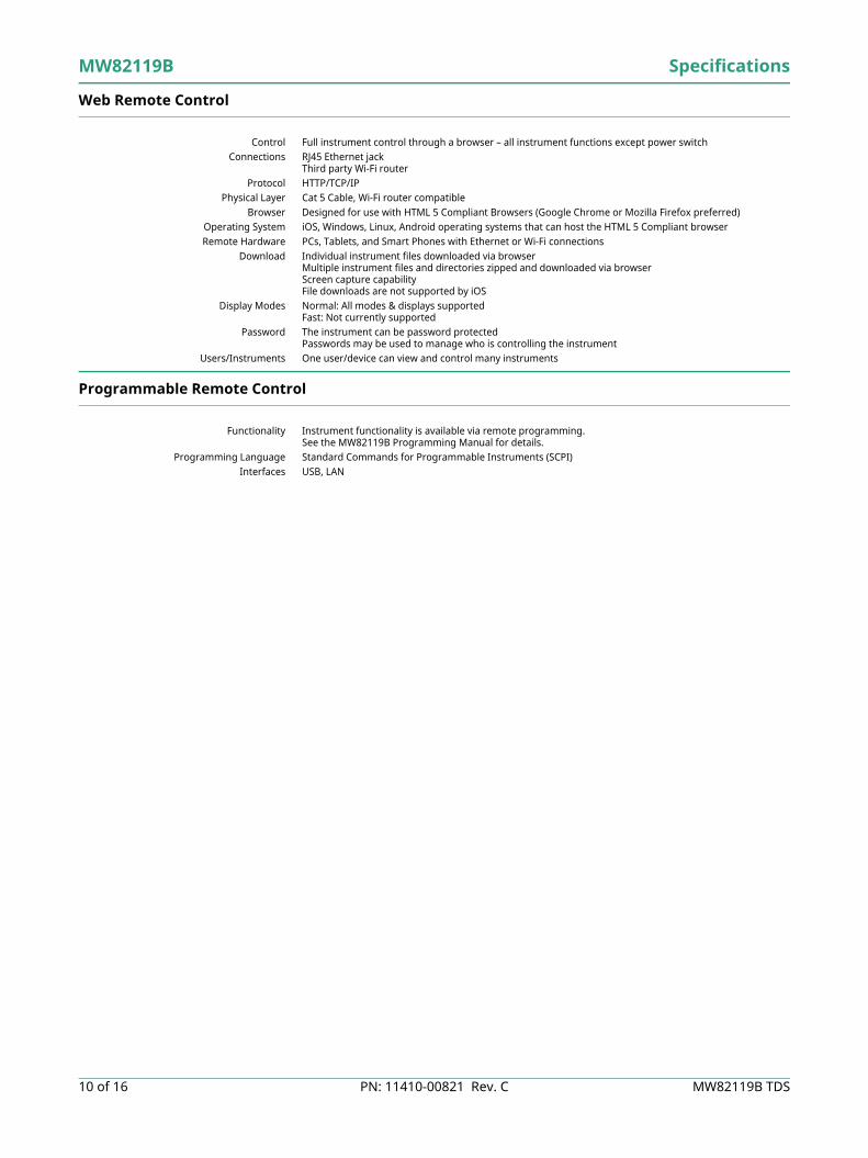
Web Remote Control
Control Full instrument control through a browser – all instrument functions except power switchConnections RJ45 Ethernet jack
Third party Wi-Fi routerProtocol HTTP/TCP/IP
Physical Layer Cat 5 Cable, Wi-Fi router compatibleBrowser Designed for use with HTML 5 Compliant Browsers (Google Chrome or Mozilla Firefox preferred)
Operating System iOS, Windows, Linux, Android operating systems that can host the HTML 5 Compliant browserRemote Hardware PCs, Tablets, and Smart Phones with Ethernet or Wi-Fi connections
Download Individual instrument files downloaded via browserMultiple instrument files and directories zipped and downloaded via browserScreen capture capabilityFile downloads are not supported by iOS
Display Modes Normal: All modes & displays supportedFast: Not currently supported
Password The instrument can be password protectedPasswords may be used to manage who is controlling the instrument
Users/Instruments One user/device can view and control many instruments
Programmable Remote Control
Functionality Instrument functionality is available via remote programming.See the MW82119B Programming Manual for details.
Programming Language Standard Commands for Programmable Instruments (SCPI)Interfaces USB, LAN
Specifications MW82119B
MW82119B TDS PN: 11410-00821 Rev. C 11 of 16
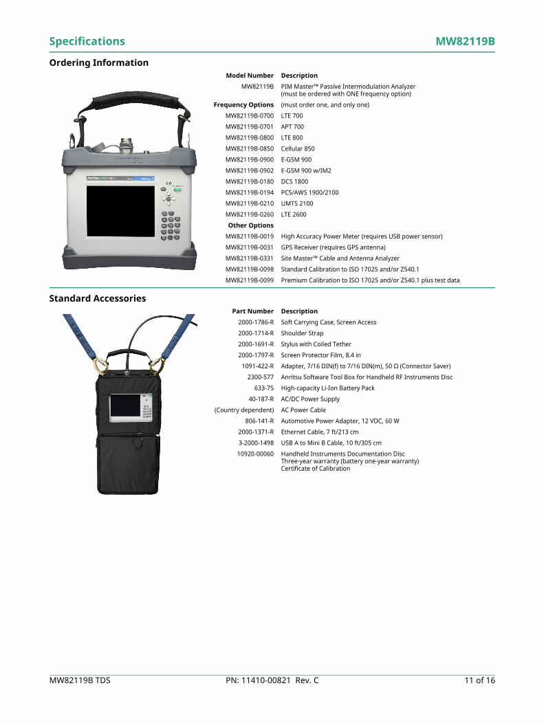
Ordering Information
Standard Accessories
Model Number Description
MW82119B PIM Master™ Passive Intermodulation Analyzer (must be ordered with ONE frequency option)
Frequency Options (must order one, and only one)
MW82119B-0700 LTE 700
MW82119B-0701 APT 700
MW82119B-0800 LTE 800
MW82119B-0850 Cellular 850
MW82119B-0900 E-GSM 900
MW82119B-0902 E-GSM 900 w/IM2
MW82119B-0180 DCS 1800
MW82119B-0194 PCS/AWS 1900/2100
MW82119B-0210 UMTS 2100
MW82119B-0260 LTE 2600
Other Options
MW82119B-0019 High Accuracy Power Meter (requires USB power sensor)
MW82119B-0031 GPS Receiver (requires GPS antenna)
MW82119B-0331 Site Master™ Cable and Antenna Analyzer
MW82119B-0098 Standard Calibration to ISO 17025 and/or Z540.1
MW82119B-0099 Premium Calibration to ISO 17025 and/or Z540.1 plus test data
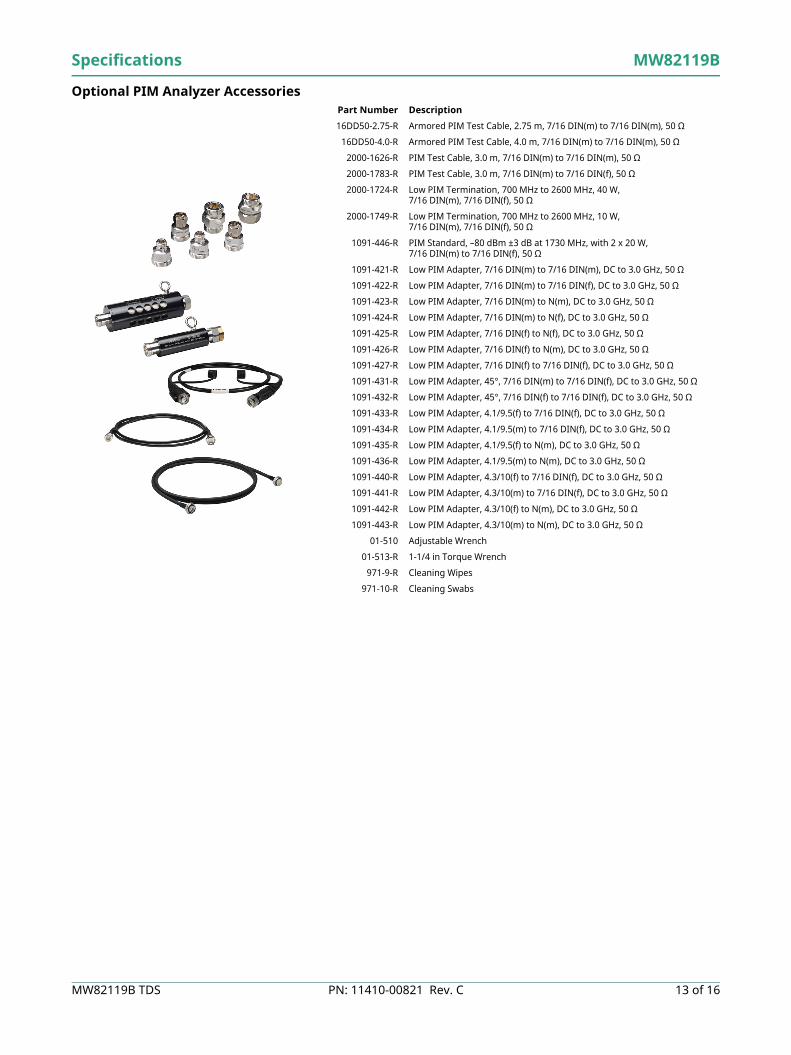
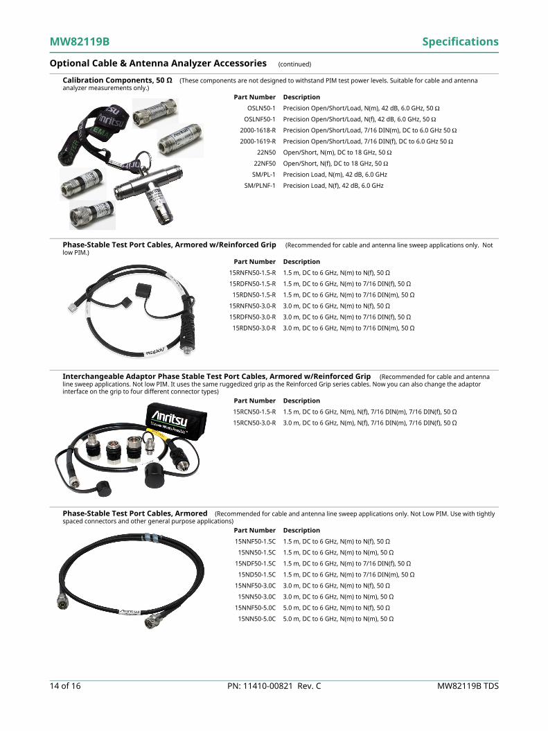
Calibration Components, 50 Ω (These components are not designed to withstand PIM test power levels. Suitable for cable and antenna analyzer measurements only.)
Phase-Stable Test Port Cables, Armored w/Reinforced Grip (Recommended for cable and antenna line sweep applications only. Not low PIM.)
Interchangeable Adaptor Phase Stable Test Port Cables, Armored w/Reinforced Grip (Recommended for cable and antenna line sweep applications. Not low PIM. It uses the same ruggedized grip as the Reinforced Grip series cables. Now you can also change the adaptor interface on the grip to four different connector types)
Phase-Stable Test Port Cables, Armored (Recommended for cable and antenna line sweep applications only. Not Low PIM. Use with tightly spaced connectors and other general purpose applications)
MW82119B TDS, PN: 11410-00821, Rev. CCopyright October 2015, Anritsu Company, USA. All Rights Reserved.
® Anritsu All trademarks are registered trademarks of their respective companies.Anritsu utilizes recycled paper and environmentally conscious inks and toner.
Data subject to change without notice.For the most recent specifications, visit: www.anritsu.com.1616 of 16
Training at AnritsuAnritsu has designed courses to help you stay up to date with technologies important to your job. For available training courses, visit: www.anritsu.com/training
● United StatesAnritsu Company1155 East Collins Blvd, Suite 100 Richardson, TX 75081, U.S.A.Toll Free: 1-800-267-4878Phone: +1-972-644-1777Fax: +1-972-671-1877● CanadaAnritsu Electronics Ltd.700 Silver Seven Road, Suite 120 Kanata, Ontario K2V 1C3, CanadaPhone: +1-613-591-2003Fax: +1-613-591-1006● BrazilAnritsu Electrônica Ltda.Praça Amadeu Amaral, 27 - 1 Andar01327-010 Bela Vista, São Paulo, BrazilPhone: +55-11-3283-2511Fax: +55-11-3288-6940● MexicoAnritsu Company, S.A. de C.V.Av. Ejército Nacional No. 579 Piso 9, Col. Granada11520 México, D.F., MéxicoPhone: +52-55-1101-2370Fax: +52-55-5254-3147● United KingdomAnritsu EMEA Ltd.200 Capability GreenLuton, Bedfordshire LU1 3LUUnited KingdomPhone: +44-1582-433280Fax: +44-1582-731303● FranceAnritsu S.A.12 Avenue du QuébecBâtiment Iris 1-Silic 61291140 Villebon-sur-Yvette, FrancePhone: +33-1-60-92-15-50Fax: +33-1-64-46-10-65● GermanyAnritsu GmbHNemetschek Haus, Konrad-Zuse-Platz 181829 München, GermanyPhone: +49-89-442308-0Fax: +49-89-442308-55
● ItalyAnritsu S.r.l.Via Elio Vittorini 12900144 Roma, ItalyPhone: +39-06-509-9711Fax: +39-06-502-2425● SwedenAnritsu ABKistagången 20B164 40 KISTA, SwedenPhone: +46-8-534-707-00Fax: +46-8-534-707-30● FinlandAnritsu ABTeknobulevardi 3-5FI-01530 Vantaa, FinlandPhone: +358-20-741-8100Fax: +358-20-741-8111● DenmarkAnritsu A/SKay Fiskers Plads 92300 Copenhagen S, DenmarkPhone: +45-7211-2200Fax: +45-7211-2210● RussiaAnritsu EMEA Ltd.Representation Office in RussiaTverskaya str. 16/2, bld. 1, 7th floorMoscow, 125009, RussiaPhone: +7-495-363-1694Fax: +7-495-935-8962● SpainAnritsu EMEA Ltd.Representation Office in SpainEdificio Cuzco IV, Po. de la Castellana, 141, Pta. 828046, Madrid, SpainPhone: +34-915-726-761Fax: +34-915-726-621● United Arab EmiratesAnritsu EMEA Ltd.Dubai Liaison OfficeP O Box 500413 - Dubai Internet CityAl Thuraya Building, Tower 1, Suite 701, 7th FloorDubai, United Arab EmiratesPhone: +971-4-3670352Fax: +971-4-3688460
● IndiaAnritsu India Private Limited2nd & 3rd Floor, #837/1, Binnamangla 1st StageIndiranagar, 100ft Road, Bangalore - 560038, IndiaPhone: +91-80-4058-1300Fax: +91-80-4058-1301● SingaporeAnritsu Pte. Ltd.11 Chang Charn Road, #04-01, Shriro HouseSingapore 159640Phone: +65-6282-2400Fax: +65-6282-2533● P.R. China (Shanghai)Anritsu (China) Co., Ltd.27th Floor, Tower ANew Caohejing International Business CenterNo. 391 Gui Ping Road Shanghai, Xu Hui Di DistrictShanghai 200233, P.R. ChinaPhone: +86-21-6237-0898Fax: +86-21-6237-0899● P.R. China (Hong Kong)Anritsu Company Ltd.Unit 1006-7, 10/F., Greenfield TowerConcordia PlazaNo. 1 Science Museum Road, Tsim Sha Tsui EastKowloon, Hong Kong, P. R. ChinaPhone: +852-2301-4980Fax: +852-2301-3545● JapanAnritsu Corporation8-5, Tamura-cho, Atsugi-shi Kanagawa, 243-0016 JapanPhone: +81-46-296-1221Fax: +81-46-296-1238● KoreaAnritsu Corporation, Ltd.5FL, 235 Pangyoyeok-ro, Bundang-guSeongnam-siGyeonggi-do, 463-400 KoreaPhone: +82-31-696-7750Fax: +82-31-696-7751● AustraliaAnritsu Pty Ltd.Unit 21/270 Ferntree Gully RoadNotting Hill, Victoria, 3168, AustraliaPhone: +61-3-9558-8177Fax: +61-3-9558-8255● TaiwanAnritsu Company Inc.7F, No. 316, Sec. 1, Neihu Rd, Taipei 114, TaiwanPhone: +886-2-8751-1816Fax: +886-2-8751-1817