Application Note Overview: The MW82119A/B PIM Master™ from Anritsu is a family of high power, battery operated PIM test instruments designed for maximum portability. These instruments utilize a filter combiner to maximize RF efficiency and minimize battery consumption during use. The F 1 and F 2 frequency range for each analyzer has been designed to cover the maximum possible range of IM3 frequencies for that band. The fact that some frequencies in the downlink band are not able to be selected (guard band frequencies) has no impact on the instrument’s ability to test the full range of possible IM3 frequencies. Background: Passive intermodulation (PIM) is interference generated by the downlink signals at a cell site interacting with non-linear junctions or non-linear materials (PIM sources) in the RF path. These PIM sources act like a mixer, generating new frequencies that are mathematical combinations of the downlink frequencies present. PIM that falls in an operator’s uplink band can elevate the noise floor, resulting in higher dropped call rates, higher access failures and lower data transmission rates. The PIM Master from Anritsu is a specialized test instrument designed to help operators find and eliminate PIM sources at a cell site. The PIM Master generates two equal power test signals at frequencies F 1 and F 2 , combines these test signals together and feeds them into the system under test. The specified intermodulation product (2F 1 ± F 2 ), (2F 2 ± F 1 ) etc. that falls within an operator’s uplink band is measured and displayed to the test operator. The third order intermodulation products (IM3) typically represent the worst case condition of these unwanted signals. By measuring the magnitude of the IM3 produced by the test signals F 1 and F 2 , operators are able to characterize the linearity of that system. The higher the linearity, the lower IM3 will be. When the linearity of the system is improved, all IM products that might fall in an operator’s uplink band can be reduced to a level that will not cause interference. PIM test equipment uses either a Filter Combiner or a Hybrid Combiner to combine the two test signals before presenting them to the system under test. Each combining technology has advantages and disadvantages that must be considered when designing PIM test instruments. PIM Master ™ Transmit Frequency Range
Transcript
Application Note
Overview:The MW82119A/B PIM Master™ from Anritsu is a family of high power, battery operated PIM test instruments designed for maximum portability. These instruments utilize a filter combiner to maximize RF efficiency and minimize battery consumption during use. The F1 and F2 frequency range for each analyzer has been designed to cover the maximum possible range of IM3 frequencies for that band. The fact that some frequencies in the downlink band are not able to be selected (guard band frequencies) has no impact on the instrument’s ability to test the full range of possible IM3 frequencies.
Background:Passive intermodulation (PIM) is interference generated by the downlink signals at a cell site interacting with non-linear junctions or non-linear materials (PIM sources) in the RF path. These PIM sources act like a mixer, generating new frequencies that are mathematical combinations of the downlink frequencies present. PIM that falls in an operator’s uplink band can elevate the noise floor, resulting in higher dropped call rates, higher access failures and lower data transmission rates.
The PIM Master from Anritsu is a specialized test instrument designed to help operators find and eliminate PIM sources at a cell site. The PIM Master generates two equal power test signals at frequencies F1 and F2, combines these test signals together and feeds them into the system under test. The specified intermodulation product (2F1 ± F2), (2F2 ± F1) etc. that falls within an operator’s uplink band is measured and displayed to the test operator.
The third order intermodulation products (IM3) typically represent the worst case condition of these unwanted signals. By measuring the magnitude of the IM3 produced by the test signals F1 and F2, operators are able to characterize the linearity of that system. The higher the linearity, the lower IM3 will be. When the linearity of the system is improved, all IM products that might fall in an operator’s uplink band can be reduced to a level that will not cause interference.
PIM test equipment uses either a Filter Combiner or a Hybrid Combiner to combine the two test signals before presenting them to the system under test. Each combining technology has advantages and disadvantages that must be considered when designing PIM test instruments.
PIM Master™ Transmit Frequency Range
22
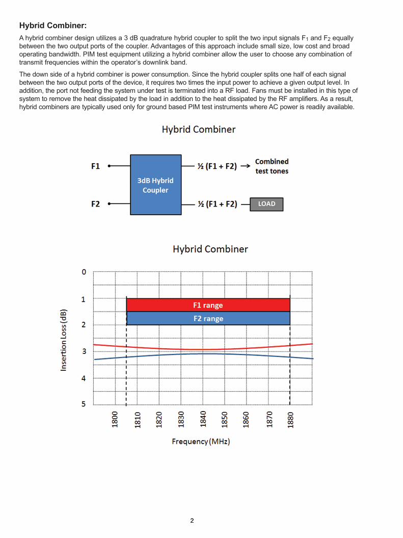
Hybrid Combiner:A hybrid combiner design utilizes a 3 dB quadrature hybrid coupler to split the two input signals F1 and F2 equally between the two output ports of the coupler. Advantages of this approach include small size, low cost and broad operating bandwidth. PIM test equipment utilizing a hybrid combiner allow the user to choose any combination of transmit frequencies within the operator’s downlink band.
The down side of a hybrid combiner is power consumption. Since the hybrid coupler splits one half of each signal between the two output ports of the device, it requires two times the input power to achieve a given output level. In addition, the port not feeding the system under test is terminated into a RF load. Fans must be installed in this type of system to remove the heat dissipated by the load in addition to the heat dissipated by the RF amplifiers. As a result, hybrid combiners are typically used only for ground based PIM test instruments where AC power is readily available.
33
Filter Combiner:A filter combiner design utilizes cavity bandpass filters to efficiently combine signals from two neighboring frequency bands onto a common output port. Cavity bandpass filters are machined from solid blocks of aluminum and often silver plated to minimize conductive losses. As a result, very little RF energy is lost as F1 and F2 pass through the combiner. Since the amplifiers run at lower power and very little heat is dissipated through the filter, these systems can often be designed to operate without fans. Due to the lower over-all power consumption, filter combiners are very useful for battery operated PIM test solutions where long battery life is a chief concern.
The down side of a filter combiner is size, weight, cost and frequency bandwidth. Filter combiners do not allow all frequencies in the downlink band to be selected for PIM testing. Rather, a space or guard band is required to achieve isolation between neighboring frequency bands. As the guard band becomes smaller, more cavities are required, causing the size and the insertion loss of the filter to increase. Guard band spacing should be designed to be as large as possible to minimize the overall size and weight of the PIM test equipment.
4
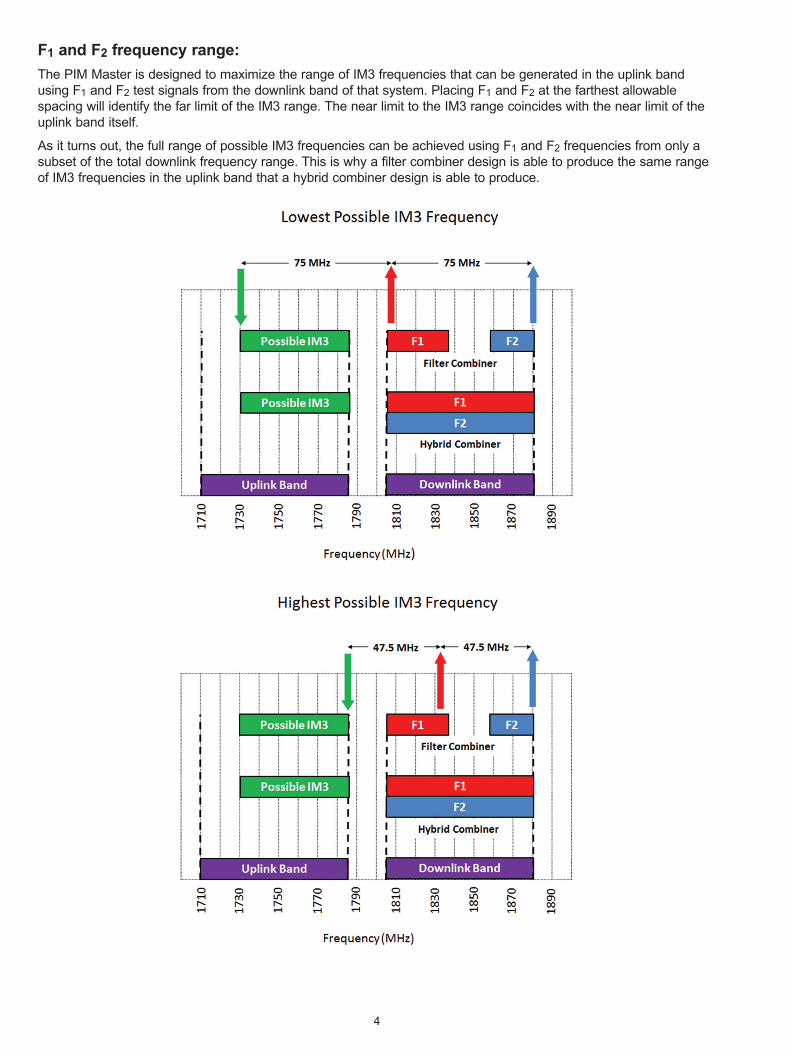
F1 and F2 frequency range:The PIM Master is designed to maximize the range of IM3 frequencies that can be generated in the uplink band using F1 and F2 test signals from the downlink band of that system. Placing F1 and F2 at the farthest allowable spacing will identify the far limit of the IM3 range. The near limit to the IM3 range coincides with the near limit of the uplink band itself.
As it turns out, the full range of possible IM3 frequencies can be achieved using F1 and F2 frequencies from only a subset of the total downlink frequency range. This is why a filter combiner design is able to produce the same range of IM3 frequencies in the uplink band that a hybrid combiner design is able to produce.
5
PIM Master frequency range:
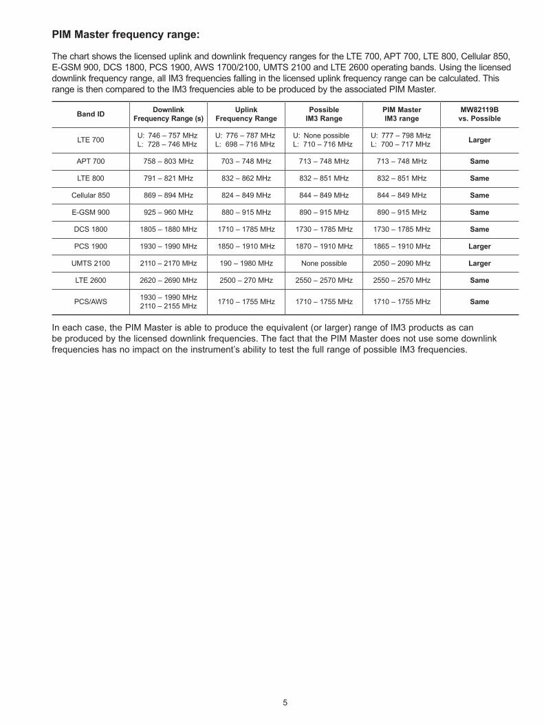
The chart shows the licensed uplink and downlink frequency ranges for the LTE 700, APT 700, LTE 800, Cellular 850, E-GSM 900, DCS 1800, PCS 1900, AWS 1700/2100, UMTS 2100 and LTE 2600 operating bands. Using the licensed downlink frequency range, all IM3 frequencies falling in the licensed uplink frequency range can be calculated. This range is then compared to the IM3 frequencies able to be produced by the associated PIM Master.
In each case, the PIM Master is able to produce the equivalent (or larger) range of IM3 products as can be produced by the licensed downlink frequencies. The fact that the PIM Master does not use some downlink frequencies has no impact on the instrument’s ability to test the full range of possible IM3 frequencies.
® Anritsu All trademarks are registered trademarks of their respective companies. Data subject to change without notice. For the most recent specifications visit: www.anritsu.com
Anritsu utilizes recycled paper and environmentally conscious inks and toner.
• United States Anritsu Company1155 East Collins Boulevard, Suite 100, Richardson, TX, 75081 U.S.A. Toll Free: 1-800-267-4878 Phone: +1-972-644-1777 Fax: +1-972-671-1877
• Brazil Anritsu Electrônica Ltda.Praça Amadeu Amaral, 27 - 1 Andar 01327-010 - Bela Vista - São Paulo - SP - Brazil Phone: +55-11-3283-2511 Fax: +55-11-3288-6940
• Russia Anritsu EMEA Ltd. Representation Office in RussiaTverskaya str. 16/2, bld. 1, 7th floor. Russia, 125009, Moscow Phone: +7-495-363-1694 Fax: +7-495-935-8962
• United Arab Emirates Anritsu EMEA Ltd. Dubai Liaison OfficeP O Box 500413 - Dubai Internet City Al Thuraya Building, Tower 1, Suite 701, 7th Floor Dubai, United Arab Emirates Phone: +971-4-3670352 Fax: +971-4-3688460
• India Anritsu India Pvt Ltd.2nd & 3rd Floor, #837/1, Binnamangla 1st Stage, Indiranagar, 100ft Road, Bangalore - 560038, India Phone: +91-80-4058-1300 Fax: +91-80-4058-1301
• P. R. China (Shanghai) Anritsu (China) Co., Ltd.27th Floor, Tower A, New Caohejing International Business Center No. 391 Gui Ping Road Shanghai, Xu Hui Di District, Shanghai 200233, P.R. China Phone: +86-21-6237-0898 Fax: +86-21-6237-0899
• P. R. China (Hong Kong) Anritsu Company Ltd.Unit 1006-7, 10/F., Greenfield Tower, Concordia Plaza, No. 1 Science Museum Road, Tsim Sha Tsui East, Kowloon, Hong Kong, P. R. China Phone: +852-2301-4980 Fax: +852-2301-3545
• Japan Anritsu Corporation8-5, Tamura-cho, Atsugi-shi, Kanagawa, 243-0016 Japan Phone: +81-46-296-1221 Fax: +81-46-296-1238
• Korea Anritsu Corporation, Ltd.5FL, 235 Pangyoyeok-ro, Bundang-gu, Seongnam-si, Gyeonggi-do, 463-400 Korea Phone: +82-31-696-7750 Fax: +82-31-696-7751
• Australia Anritsu Pty Ltd.Unit 21/270 Ferntree Gully Road, Notting Hill, Victoria 3168, Australia Phone: +61-3-9558-8177 Fax: +61-3-9558-8255
• Taiwan Anritsu Company Inc.7F, No. 316, Sec. 1, Neihu Rd., Taipei 114, Taiwan Phone: +886-2-8751-1816 Fax: +886-2-8751-1817