30
UAV-1001626-001 Rev F ECCN 7A994 Page 1 | 30 ping20Si User and Installation Guide
UAV-1001626-001 Rev F
ECCN 7A994 Page 1 | 30
ping20Si
User and Installation Guide

UAV-1001626-001 Rev F
ECCN 7A994 Page 2 | 30
© 2020 uAvionix Corporation. All rights reserved.
uAvionix Corporation
300 Pine Needle Lane
Bigfork, MT 59911
http://www.uavionix.com
http://www.uavionix.com/support
Except as expressly provided herein, no part of this guide may be
reproduced, transmitted, disseminated, downloaded or stored in any
storage medium, for any purpose without the express written permission of
uAvionix. uAvionix grants permissions to download a single copy of this
guide onto an electronic storage medium to be viewed for personal use,
provided that the complete text of this copyright notice is retained.
Unauthorized commercial distribution of this manual or any revision hereto
is strictly prohibited.
uAvionix® is a registered trademark of uAvionix Corporation, and may not
be used without express permission of uAvionix.

UAV-1001626-001 Rev F
ECCN 7A994 Page 3 | 30
1 Revision History
Revision Date Comments
A 12/9/2017 Initial release
B 4/4/2019 Input power requirements
C 6/18/2019 Including ambient temperature with battery pack
D 7/30/2019
E 10/26/2019 Update product label compliant to RED RED conformity statement added
F 5/19/2020 Update Support Contact and minor formatting edits

UAV-1001626-001 Rev F
ECCN 7A994 Page 4 | 30
2 Warnings / Disclaimers
All device operational procedures must be learned on the ground.
uAvionix is not liable for damages arising from the use or misuse of this
product.
This equipment has not received a FAA transmit license and is
for development use only.
The following required statement from the Federal Communications
Commission (FCC) applies to United States based entities with the
exception of direct sales to the U.S. Government and units directly
exported by uAvionix:
This device has not been authorized as required by the rules of the Federal
Communications Commission. This device is not, and may not be, offered
for sale or lease, or sold or leased, until authorization is obtained.
This equipment is classified by the United States Department of
Commerce's Bureau of Industry and Security (BIS) as Export Control
Classification Number (ECCN) 7A994.
These items are controlled by the U.S. Government and authorized for
export only to the country of ultimate destination for use by the ultimate
consignee or end-user(s) herein identified. They may not be resold,
transferred, or otherwise disposed of, to any other country or to any person
other than the authorized ultimate consignee or end-user(s), either in their
original form or after being incorporated into other items, without first
obtaining approval from the U.S. government or as otherwise authorized by
U.S. law and regulations.
!

UAV-1001626-001 Rev F
ECCN 7A994 Page 5 | 30
3 Limited Warranty
uAvionix products are warranted to be free from defects in material and
workmanship for one year from the installation in the aircraft. For the
duration of the warranty period, uAvionix, at its sole option, will repair or
replace any product which fails under normal use. Such repairs or
replacement will be made at no charge to the customer for parts or labor,
provided that the customer shall be responsible for any transportation cost.
This warranty does not apply to cosmetic damage, consumable parts,
damage caused by accident, abuse, misuse, water, fire or flood, damage
caused by unauthorized servicing, or product that has been modified or
altered.
IN NO EVENT, SHALL UAVIONIX BE LIABLE FOR ANY INCIDENTAL,
SPECIAL, INDIRECT OR CONSEQUENTIAL DAMAGES, WHETHER
RESULTING FROM THE USE, MISUSE OR INABILITY TO USE THE
PRODUCT OR FROM DEFECTS IN THE PRODUCT. SOME STATES DO
NOT ALLOW THE EXCLUSION OF INCIDENTAL OR CONSEQUENTIAL
DAMAGES, SO THE ABOVE LIMITATIONS MAY NOT APPLY TO YOU.
Warranty Service
Warranty repair service shall be provided directly by uAvionix.

UAV-1001626-001 Rev F
ECCN 7A994 Page 6 | 30
4 Contents 1 Revision History ................................................................................. 3
2 Warnings / Disclaimers ....................................................................... 4
3 Limited Warranty ................................................................................ 5
5 Introduction ........................................................................................ 8
5.1 Description .................................................................................. 8
5.2 RED conformity ........................................................................... 8
5.3 Interfaces .................................................................................... 9
5.4 Software and Airborne Electronic Hardware Configuration. .........10
5.5 Supplied Accessories .................................................................10
6 Technical Specifications ....................................................................11
6.1 Markings .....................................................................................12
7 Equipment Limitations .......................................................................12
7.1 Installation ..................................................................................12
7.1.1 Modifications and Use Outside of Intended Scope ................12
7.1.2 Deviations .............................................................................12
8 Equipment Installation .......................................................................13
8.1 Unpacking and Inspecting...........................................................13
8.2 Mounting ....................................................................................13
8.3 Connections ...............................................................................14
.............................................................................................................15
8.4 Wiring Diagram ...........................................................................16
Mating Connector: Molex 0436450200 ..................................................16
8.5 Cooling Requirements ................................................................17
8.6 Antenna Installation ....................................................................17
9 Programming.....................................................................................18
9.1 Default Control ...........................................................................19

UAV-1001626-001 Rev F
ECCN 7A994 Page 7 | 30
9.2 ICAO Number .............................................................................19
9.3 Callsign ......................................................................................20
9.4 Aircraft Category.........................................................................20
9.5 VFR Squawk Code .....................................................................20
9.6 Aircraft Maximum Speed ............................................................20
9.7 ADS-B RX Capability ..................................................................20
9.8 Aircraft Length / Width ................................................................21
9.9 GPS Antenna Offset Lateral / Longitudinal ..................................22
10 PC Control Application ......................................................................23
11 Post Installation Checklist ..................................................................24
12 Continued Airworthiness ....................................................................25
13 Environmental Qualification Forms ....................................................26

UAV-1001626-001 Rev F
ECCN 7A994 Page 8 | 30
5 Introduction
5.1 Description
The ping20Si is a Mode S, 20W transponder with support for ADS-B
extended squitter. The ping20Si has a nominal power output of 20W. The
integrated GPS sensor meets the requirements of DO-229D.
Meets the requirements of:
RTCA DO-181E Level 2els (20W output power level)
RTCA DO-260B Class B1S
RTCA DO-176B Level C
RTCA DO-254 Level C
RTCA DO-160G
RTCA DO-229D Class Beta 1
ICAO Annex 10, Volume IV
EuroCAE ED-115 Class LcF
EU-RED Annex VII
This transponder replies to both legacy Mode A/C interrogations and to
Mode S interrogations from both ground radar and airborne collision
avoidance systems. In all cases, the interrogations are received by the
transponder on 1030MHz and replies are transmitted on 1090MHz.
5.2 RED conformity
Hereby, uAvionix Corporation declares that the radio equipment type
ping20Si is in compliance with Directive 2014/53/EU. The full text of the EU
declaration of conformity is available at the following internet address:
https://uavionix.store/info/red-conformity

UAV-1001626-001 Rev F
ECCN 7A994 Page 9 | 30
5.3 Interfaces
The ping20Si has a SMA antenna connection, a 4-pin Control interface and
a 5-pin programming interface.
Control Interface
The control interface supports the MavLink protocol and can be directly
connected to the TELEM port. Additionally, GDL90 Control and status is
also supported. Protocol switching is automatic.
Protocol Message Type
CONTROL COM1 RX 1200-115200bps
GDL90 Appendix A
[^CS] Callsign [^MD] Mode
SAGETECH [0x02] Preflight [0x03] Operating [0x05] Data Request
Protocol Message Type
STATUS COM1 TX 1200-115200bps
GLD90 Appendix B
[010] Heartbeat [1010] Ownship [1110] Geo Altitude
SAGETECH [0x80] Acknowledge [0x81] Installation Response [0x82] Preflight Response [0x83] Status Response
The Interface Control Document (ICD) can be downloaded from:
www.uavioinix.com

UAV-1001626-001 Rev F
ECCN 7A994 Page 10 | 30
5.4 Software and Airborne Electronic Hardware
Configuration.
Part Part Number Revision
Software
Airborne Electronic Hardware
5.5 Supplied Accessories
Part Part Number Revision
ping20Si UAV-10001625-001
Antenna UAV-10000295-001
Power Cable
PingProg
Programming Cable JST5p-5p
Control Cable JST4p-4p
PixHawk1 cable
PixHawk 2 cable

UAV-1001626-001 Rev F
ECCN 7A994 Page 11 | 30
6 Technical Specifications
SPECIFICATION Operating Altitude unrestricted
Max Cruising Speed unrestricted
Transmit Power (Max) 45dBm, 32W
1030 Receive Sensitivity -61±3 dBm
RF Impedance 50Ω
Host Serial Communications SageTech, GDL90
Calibrated Pressure Altitude 85,000 ft
Export Compliance ECCN 7A994
Supply Voltage 11-28V
Power Consumption (ON & ALT) 1W
Power Consumption (STBY) 0.5W
Transponder Performance Standard RTCA DO-181E
Class 20W
Level 2els
ADS-B Performance Standard RTCA DO-260B
Class B1S
Pressure Altitude Standard SAE AS8003
Granted Certifications TSO-C199 (GPS)
Compliance
DO-181E Class 1 Level 1els (20W output power level) DO-260B Class B1S (20W output power level) DO-160F ICAO Annex 10, Volume IV EuroCAE ED-115 Class Lc2 es V3 (20W output power level) EU-RED Annex VII
Environmental RTCA DO-160F
Software RTCA DO-178B
Hardware RTCA DO-254 Level C
Operating Temperature -45°C to +80°C/+55°C*
Storage Temperature -55°C to +85°C
Transmitter Modulation 6M75 V1D
Weight 20 grams
Height 17mm
Length 40mm
Width 35mm
Host Interface Connector 4p JST
RF Connector SMA
*based on max. operating temperature with battery pack.

UAV-1001626-001 Rev F
ECCN 7A994 Page 12 | 30
6.1 Markings
7 Equipment Limitations
7.1 Installation
7.1.1 Modifications and Use Outside of Intended Scope
This device has been designed and tested to conform to all applicable
standards in the original form and when configured with the components
shipped with the device. It is not permissible to modify the device, use the
device for any use outside of the intended scope, or use the device with
any antenna other than the one shipped with the device.
7.1.2 Deviations
Output power is limited to 20W.

UAV-1001626-001 Rev F
ECCN 7A994 Page 13 | 30
8 Equipment Installation
This section describes the installation of ping20Si and related accessories
in the aircraft, including mounting, wiring, and connections.
8.1 Unpacking and Inspecting
Carefully unpack the device and make a visual inspection of the unit for
evidence of any damage incurred during shipment. If the unit is damaged,
notify the shipping company to file a claim for the damage. To justify your
claim, save the original shipping container and all packing materials.
8.2 Mounting
The ping20Si is designed to be mounted in any convenient location in the
cockpit, the cabin, or an avionics bay.
The following installation procedure should be followed, remembering to
allow adequate space for installation of cables and connectors.
• Select a position in the aircraft that is not too close to any high
external heat source. The ping20Si is not a significant heat source
itself and does not need to be kept away from other devices for this
reason.
• Avoid sharp bends and placing the cables too near to the aircraft
control cables.
• Secure the transponder to the aircraft via the supplied mounting tape.
It should be mounted on a flat surface.

UAV-1001626-001 Rev F
ECCN 7A994 Page 14 | 30
8.3 Connections
Whenever power is supplied to the transponder, a 50ohm load
must be provided to the SMA connection. You can use the
supplied antenna or a commercially available 50ohm load.
!

UAV-1001626-001 Rev F
ECCN 7A994 Page 15 | 30

UAV-1001626-001 Rev F
ECCN 7A994 Page 16 | 30
8.4 Wiring Diagram
Power Interface
Pin Type Physical
1 Aircraft Power 11-15V
2 Ground
Mating Connector: Molex 0436450200 Use a 1 Amp circuit breaker for power supply protection to the ping20Si.
Power to be provided by UAV battery or separate 3S LiPo battery.
Control Interface
Pin Type Physical Rate Link
1 RX In 3.3V Serial 57600bps Control
2 TX Out 3.3V Serial 57600bps GDL 90
3 Power 5V Out
4 Ground
Mating Connector: JST ZHR-4, Pins: SZH-002T-P0.5
LEDs
LED SOLID FLASHING
RED FAULT Reply / Transmit
GREEN Powered Receiving Interrogation
UAV-1001626-001 Rev F
ECCN 7A994 Page 17 | 30
8.5 Cooling Requirements
ping20Si is designed to meet all applicable TSO requirements without
forced-air cooling.
Attention should, however, be given to the incorporation of cooling
provisions to limit the maximum operating temperature if ping20Si is
installed in close proximity to other Avionics. The reliability of equipment
operating in close proximity in an avionics bay can be degraded if adequate
cooling is not provided.
8.6 Antenna Installation
The following considerations should be taken into account when siting the
antenna.
• The antenna should be mounted in a vertical position when the
aircraft is in level flight.
• Where practical, plan the antenna location to keep the cable lengths
as short as possible and avoid sharp bends in the cable to minimize
the VSWR.
Electrical connection to the antenna should be protected to avoid loss of
efficiency due to exposure to liquids and moisture. All Antenna feeders
shall be installed in such a way that a minimum of RF energy is radiated
inside the aircraft.

UAV-1001626-001 Rev F
ECCN 7A994 Page 18 | 30
9 Programming
These settings are stored in the ping20Si. To change these settings, the
ping20Si is configured via the supplied pingUSB Wi-Fi adapter and mobile
device application.
Please refer to the following documentation:
Ping App iOS quick start guide:
http://uavionix.com/downloads/pingapp/uavionix-ping-app-quick-start-guide.pdf

UAV-1001626-001 Rev F
ECCN 7A994 Page 19 | 30
The transponder system should be configured during initial system
installation by a qualified technician. The configuration items list below
should be used to document the system installation for future reference.
Configuration Item Default Control Priority
Default Control Standby/Off YES
ICAO Number 0x000000
Callsign “ “ YES
Aircraft Category UAV (14)
VFR Squawk Code 1200 YES
Aircraft Maximum Speed Not Available
ADS-B RX Capability UAT RX NO
ES1090 RX NO
Aircraft Length (Meters) 0
Aircraft Width (Meters) 0
GPS Offset Lateral (Meters) 0
GP Offset Longitudinal (Meters) 0
Configuration Items List
9.1 Default Control
Select the desired control type. This setting configures the ping20Si for
Standby, On or Altitude reporting.
• Standby/Off: Disables both the transmit and receive functions.
• ON: Responds to all interrogations and transmits ADS-B Extended
Squitter messages. Reports 0000 to altitude (Mode C) interrogations.
ALT: Responds to all interrogations and transmits ADS-B Extended
Squitter messages. Reports barometric altitude to Mode C
interrogations.
9.2 ICAO Number
The ICAO address is a 24-bit number issued to the aircraft by the
registration authority of the aircraft. These addresses are usually written as
a 6-digit hexadecimal number, although you may also encounter one
written as an 8-digit octal number. The echoUAT understands the

UAV-1001626-001 Rev F
ECCN 7A994 Page 20 | 30
hexadecimal format, so you must first convert an octal number to
hexadecimal before entering.
Tip: By using the N-Number Look Up function on https://www.faa.gov,
locate and use the “Mode S Code (base 16 / hex)” value.
9.3 Callsign
The CALL SIGN can be up to an 8 digit code that corresponds to the tail
number of the aircraft. (0-9, A-F).
Note: This is typically your aircraft N-number, unless otherwise advised by
the FAA or ATC.
9.4 Aircraft Category
To assist ATC tracking of aircraft, an aircraft category can be transmitted.
9.5 VFR Squawk Code
VFR squawk (Mode 3/A) code is a pre-programmed default code when the
pilot is flying VFR and not in contact with ATC. In the USA, the VFR
squawk code is 1200 and in most parts of Europe the VFR squawk code is
7000.
9.6 Aircraft Maximum Speed
Mode S transponders can transmit their maximum airspeed characteristics
to aircraft equipped with TCAS. This information is used to identify threats
and to plan avoiding action by the TCAS equipped aircraft. The airspeeds
are grouped in ranges.
9.7 ADS-B RX Capability
The ADS-B transmissions include an indication to the ground stations of
whether the aircraft includes a 1090MHz ADS-B receiver, a UAT ADS-B
receiver, or both.

UAV-1001626-001 Rev F
ECCN 7A994 Page 21 | 30
9.8 Aircraft Length / Width
When on the ground, ADS-B transmits encoded aircraft size information
which is used by ATC to identify taxiing routes and potential conflicts. Enter
the length and width (wingspan) fields and the appropriate size codes will
be calculated for transmission.
Air Aircraft Length in Meters
Aircraft Width (wing span) in Meters
L ≤ 15 W ≤ 23
15 < L ≤ 25 28.5 < W ≤ 34
25 < L ≤ 35 33 < W ≤ 38
35 < L ≤ 45 39.5 < W ≤ 45
45 < L ≤ 55 45 < W ≤ 52
55 < L ≤ 65 59.5 < W ≤ 67
65 < L ≤ 75 72.5 < W ≤ 80
75 < L ≤ 85 W > 80
L > 85 Any
UAV-1001626-001 Rev F
ECCN 7A994 Page 22 | 30
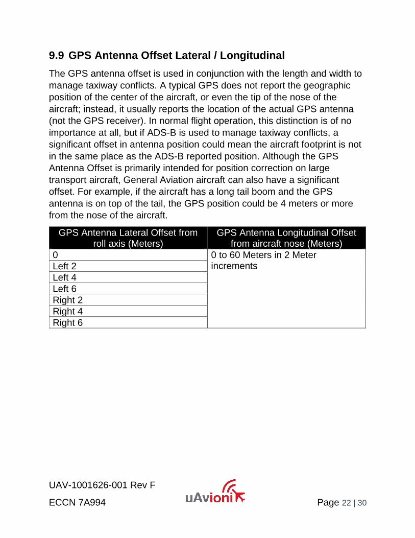
9.9 GPS Antenna Offset Lateral / Longitudinal
The GPS antenna offset is used in conjunction with the length and width to
manage taxiway conflicts. A typical GPS does not report the geographic
position of the center of the aircraft, or even the tip of the nose of the
aircraft; instead, it usually reports the location of the actual GPS antenna
(not the GPS receiver). In normal flight operation, this distinction is of no
importance at all, but if ADS-B is used to manage taxiway conflicts, a
significant offset in antenna position could mean the aircraft footprint is not
in the same place as the ADS-B reported position. Although the GPS
Antenna Offset is primarily intended for position correction on large
transport aircraft, General Aviation aircraft can also have a significant
offset. For example, if the aircraft has a long tail boom and the GPS
antenna is on top of the tail, the GPS position could be 4 meters or more
from the nose of the aircraft.
GPS Antenna Lateral Offset from roll axis (Meters)
GPS Antenna Longitudinal Offset from aircraft nose (Meters)
0 0 to 60 Meters in 2 Meter increments
Left 2
Left 4
Left 6
Right 2
Right 4
Right 6
UAV-1001626-001 Rev F
ECCN 7A994 Page 23 | 30
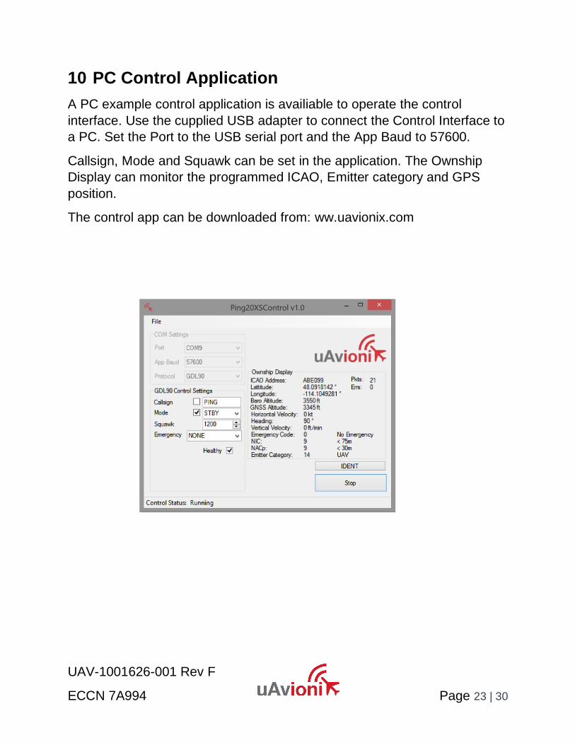
10 PC Control Application
A PC example control application is availiable to operate the control
interface. Use the cupplied USB adapter to connect the Control Interface to
a PC. Set the Port to the USB serial port and the App Baud to 57600.
Callsign, Mode and Squawk can be set in the application. The Ownship
Display can monitor the programmed ICAO, Emitter category and GPS
position.
The control app can be downloaded from: ww.uavionix.com

UAV-1001626-001 Rev F
ECCN 7A994 Page 24 | 30
11 Post Installation Checklist
Connect the system as shown in the Post Installation configuration
diagram.
STEP CHECK
Launch the PC Ping20XSControl application
Set Port to the USB or serial port connected to the ping20Si
Set the App Baud to 57600
Set Protocol to GDL90
Connect the Antenna
Apply power from a minimum of a 12V, 3A power source
Confirm that the Green LED comes on after power-up
‘Pkts:’ should start counting confirming that the app is talking to the transponder
Confirm ‘ICAO Address’ is correctly programmed and not 000000
Confirm ‘Baro Altitude’ is correct for your field elevation
After the GPS has had time to lock, confirm that ‘Latitude’ and ‘Longitude’ are correct
Set ‘Mode’ to ‘ALT’ and check the ‘Mode’ box
Observe the Red LED flashing about four times a second. This indicates 1090ES ADS-B transmissions
If you are in range of Radar, the Green LED will flash during interrogations
Using an EFB App such as ForeFlight mobile. Connect via WiFi to pingUSB powered by a portable USB 5V power supply.
The separation between the transponder and programmer needs to be at least 500ft
The aircraft will appear as traffic on the EFB application

UAV-1001626-001 Rev F
ECCN 7A994 Page 25 | 30
12 Continued Airworthiness
Other than for periodic functional checks required by the regulations,
ping20Si has been designed and manufactured to allow “on condition
maintenance”. This means that there are no periodic service requirements
necessary to maintain continued airworthiness, and no maintenance is
required until the equipment does not properly perform its intended
function. When service is required, a complete performance test should be
accomplished following any repair action. Repairs should only be carried
out in accordance with uAvionix service procedures.

UAV-1001626-001 Rev F
ECCN 7A994 Page 26 | 30
13 Environmental Qualification Forms
Nomenclature ping20Si ADS-B Mode S transponder
Part No: UAV-1000706-001 TSO-C199 Class A Device
Manufacturer uAvionix Inc
Address 380 Portage Ave, Palo Alto, CA 94306
Conditions DO-160G Section
Description of Conducted Tests
Temperature and Altitude 4.0 Equipment tested to Category B2
Low temperature ground survival
4.5.1 -55°C
Low Temperature Short-Time Operating
4.5.1 -45°C
Low Temperature Operating 4.5.2 -45°C
High Temperature Operating 4.5.4 +80°C / +55°C*
High Temperature Short-Time Operating
4.5.3 +80°C / +55°C*
High Temperature Ground Survival
4.5.3 +85°C / +55°C*
Loss of Cooling 4.5.5 Cooling air not required (+70°C operating without cooling)
Altitude 4.6.1 35,000feet
Decompression 4.6.2 Equipment identified as Category B2 – no test
Overpressure 4.6.3 Equipment identified as Category B2 – no test
Temperature Variation 5.0 Equipment tested to Category B2
Humidity 6.0 Equipment tested to Category B2
Operation Shocks 7.2 Equipment tested to Category B
Crash Safety 7.3 Equipment tested to Category B type 5
Vibration 8.0 Aircraft zone 2: type 3, 4, 5 to Category S level M, type 1 (Helicopters) to Category U level G
Explosion 9.0 Equipment identified as Category X – no test
Waterproofness 10.0 Equipment identified as Category X – no test
Fluids Susceptibility 11.0 Equipment identified as Category X – no test
Sand and Dust 12.0 Equipment identified as Category X – no test
Fungus 13.0 Equipment identified as Category X – no test
Salt Spray 14.0 Equipment identified as Category X – no test
Magnetic Field 15.0 Equipment identified as Category Z
Power Input 16.0 Equipment identified as Category ZX
Voltage Spike 17.0 Equipment identified as Category B
AF Conducted Susceptibility 18.0 Equipment identified as Category B
Induced Signal Susceptibility 19.0 Equipment identified as Category AC
RF Susceptibility 20.0 Equipment identified as Category TT
RF Emissions 21.0 Equipment identified as Category B
Lightening Induced Transient Susceptibility
22.0 Equipment identified as Category XXXX – no test
Lightening Direct Effects 23.0 Equipment identified as Category X – no test
Icing 24.0 Equipment identified as Category X – no test
Electrostatic Discharge 25.0 Equipment identified as Category X – no test
Fire, Flammability 26.0 Equipment identified as Category C
*based on max. operating temperature with battery pack.

UAV-1001626-001 Rev F
ECCN 7A994 Page 27 | 30
Appendix A. GDL 90 Compatible Control Protocol Format
(Control RX - RS-232 57600bps, N81)
The ping20Si receives control messages over the Control interface. The
interface uses an ASCII-text basis, with an ASCII-encoded hexadecimal
checksum. The checksum is algebraic sum of the message byte values.
Messages are delimited with a carriage return character.
A1. Physical Interface.
The Control interface uses RS-232 signaling levels. The port is configured
for the following characteristics:
• Baud Rate: 57600 baud
• Start Bits: 1
• Data Length: 8
• Stop Bits: 1
• Parity: None
• Flow Control: None
A2. Control Messages.
The following table summarizes the Control messages that the ping20Si
receives.
Msg ID Description Notes Ref
^CS Call Sign 1 min interval or on change
A2.1
^MD Operating Mode Message 1 second interval (nominal)
A2.2
^VC VFR Code 1 min interval or on change
A2.3

UAV-1001626-001 Rev F
ECCN 7A994 Page 28 | 30
A2.1 Call Sign Message
The Call Sign message provides for a user selectable callsign.
Rate: Every 1 minute or when a change occurs Message Length: 15 bytes
Byte Contents Description
1 ‘^’ ASCII ‘^’ (0x5E)
2 ‘C’ ASCII ‘C’ (0x43)
3 ‘S’ ASCII ‘S’ (0x53)
4 ‘ ‘ ASCII space (0x20)
5-12 dddddddd ASCII Flight ID (all 8 characters are mandatory, right pad with space)
13-14 dd Checksum of bytes 1 through 12. In hex ASCII i.e. “FA”
15 ‘\r’ ASCII carriage return (0x0D)
Example: ^CS UAVIONIX87\r

UAV-1001626-001 Rev F
ECCN 7A994 Page 29 | 30
A2.2 Mode Message
The mode message indicates the current operating mode. It includes the
current mode, the Ident status, current squawk code setting and
emergency code.
Rate: 1 sec (nominal) Message Length: 17 bytes
Byte Contents Description
1 ‘^’ ASCII ‘^’ (0x5E)
2 ‘M’ ASCII ‘M’ (0x4D)
3 ‘D’ ASCII ‘D’ (0x44)
4 ‘ ‘ ASCII space (0x20)
5 m See mode field table below
6 ‘,’ ASCII comma (0x2C)
7 ‘I’ See ident field table below
8 ‘,’ ASCII comma (0x2C)
9-12 dddd ASCII squawk code
13 e See emergency field table below
14 h Health bit in hex ASCII “1”
15-16 dd Checksum of bytes 1 through 14. In hex ASCII i.e. “FA”
17 ‘\r’ ASCII carriage return (0x0D)
Mode Field
m Definition ASCII
O OFF 0x4F
A STBY 0x41
C ON 0x43
S ALT 0x53
Ident Field
i Definition ASCII
I Ident Enabled 0x49
- Ident is Inactive 0x2D
Emergency Field
e Definition ASCII
0 None 0x00
1 General 0x01
2 Medical 0x02
3 Fuel 0x03
4 Com 0x04
5 Hijack 0x05
6 Downed 0x06
7 UAS Lost Link 0x07
The health indication is set to ‘1 to indicate that everything is operating
normally.
Example: ^MD A,I,23540120\r
Mode STBY, Ident active, Squawk 2354, No Emergency, Healthy

UAV-1001626-001 Rev F
ECCN 7A994 Page 30 | 30
Appendix B. GDL 90 Ownship Protocol Format.
(Control TX RS-232 57600bps, 81N)
The GDL 90 Data Interface Specification can be found at:
https://www.faa.gov/nextgen/programs/adsb/wsa/media/GDL90_Public_ICD_RevA.PDF
ping20Si transmits the following messages:
Msg ID Description Notes Ref
010 Heartbeat 1 second interval §3.1
1010 Ownship Report 1 second interval §3.4
1110 Ownship Geometric Report
1 second interval §3.8


