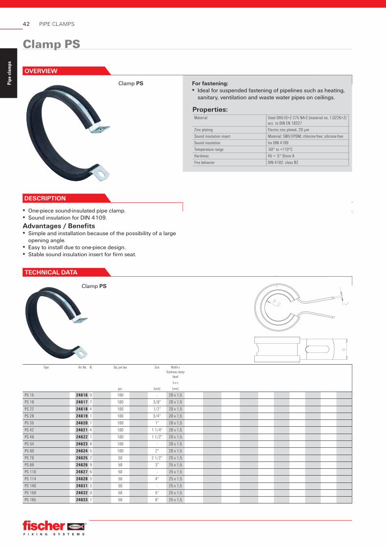
Locking screw Flat head screw with combination recessed head
Sound insulation insert Material: NR/SBR/EPDM
Sound insulation for DIN 4109
Temperature range -50° to +110°C
Hardness 60 +- 5° Shore
Fire behavior DIN 4102: class B2
PIPE CLAMPS
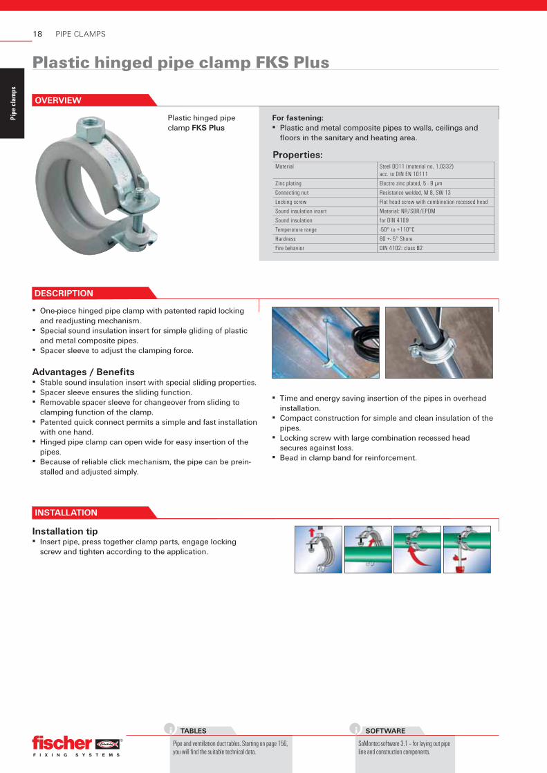
Plastic hinged pipe clamp FKS Plus
For fastening:▪ Plastic and metal composite pipes to walls, ceilings and
fl oors in the sanitary and heating area.
INSTALLATION
Installation tip▪ Insert pipe, press together clamp parts, engage locking
screw and tighten according to the application.
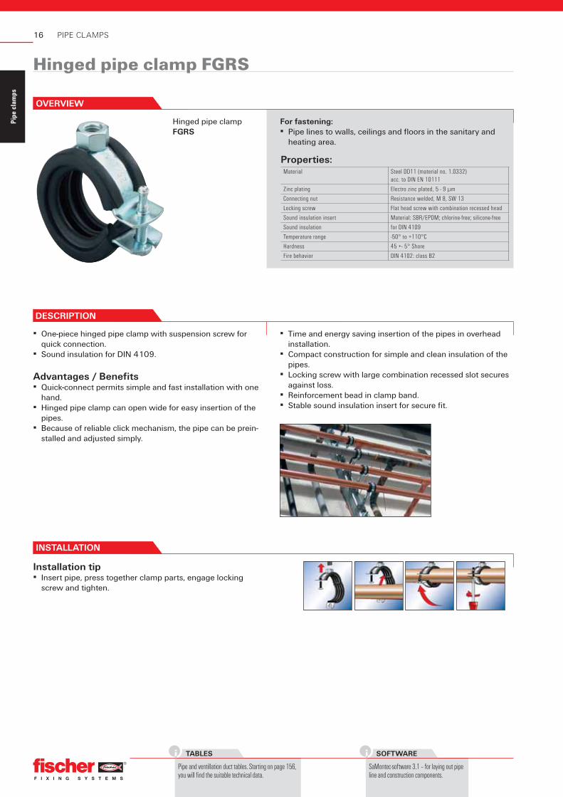
OVERVIEW
DESCRIPTION
▪ One-piece hinged pipe clamp with patented rapid locking and readjusting mechanism.
▪ Special sound insulation insert for simple gliding of plastic and metal composite pipes.
▪ Spacer sleeve to adjust the clamping force.
Advantages / Benefi ts▪ Stable sound insulation insert with special sliding properties.▪ Spacer sleeve ensures the sliding function.▪ Removable spacer sleeve for changeover from sliding to
clamping function of the clamp.▪ Patented quick connect permits a simple and fast installation
with one hand.▪ Hinged pipe clamp can open wide for easy insertion of the
pipes.▪ Because of reliable click mechanism, the pipe can be prein-
stalled and adjusted simply.
▪ Time and energy saving insertion of the pipes in overhead installation.
▪ Compact construction for simple and clean insulation of the pipes.
▪ Locking screw with large combination recessed head secures against loss.
▪ Bead in clamp band for reinforcement.
19
Pipe
cla
mps
DIAGRAMS
Starting on page 159, you will find the expansions of pipe lines.
Plastic hinged pipe clamp FKS Plus
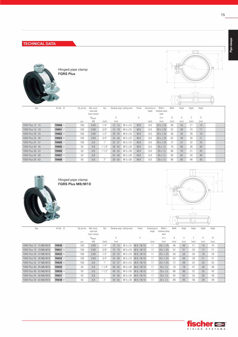
Type Art.-No. ID Qty. per box Max. recom. static load
(centr. tension)
Size Clamping range Locking screw Thread Connecting nut height
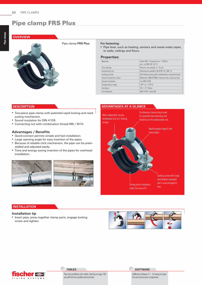
Better adaptation to pipe dimensions due to 2 locking screws.
Reinforcement bead in the clamp band.
Strong sound insulation insert for secure fi t.
Locking screw with large combination recessed slot is secured against loss.
Combination connecting thread for cost-eff ective mounting and fl exibility at the construction site.
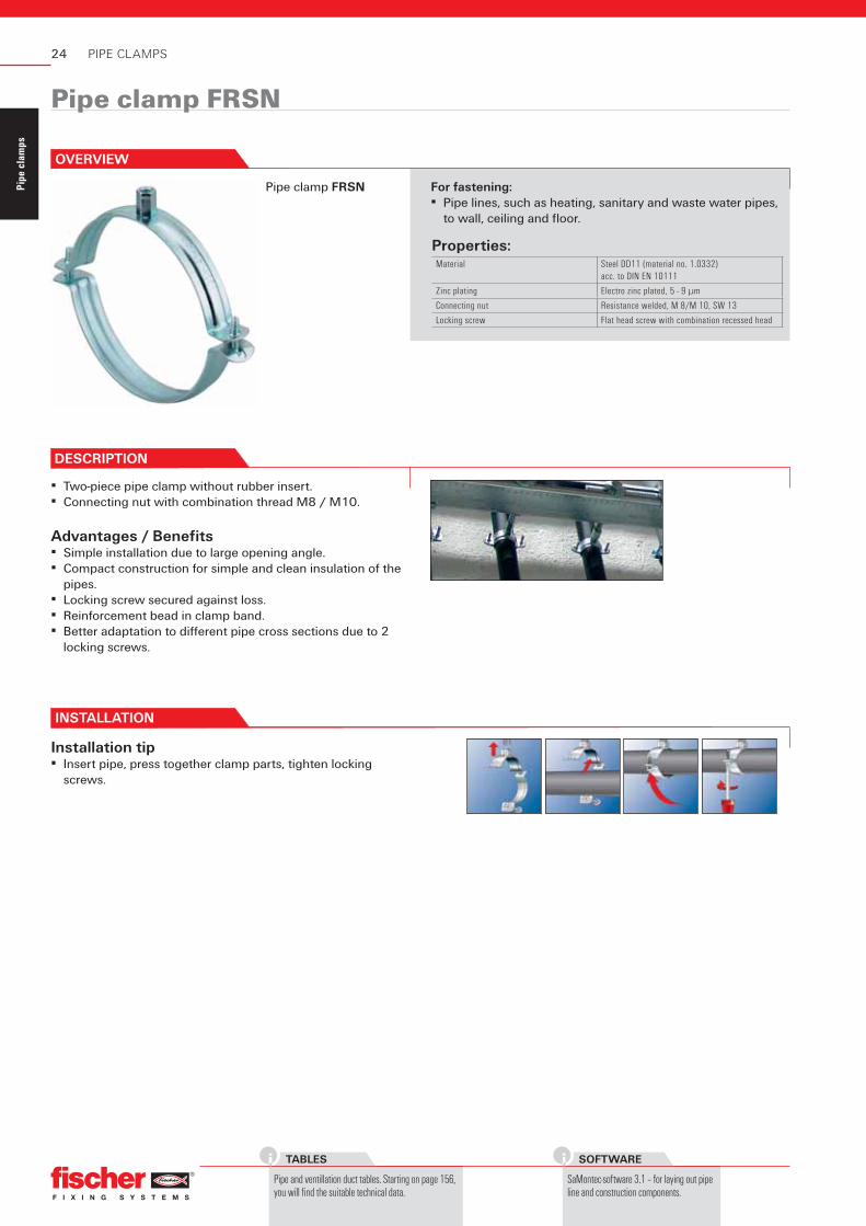
▪ Two-piece pipe clamp with patented rapid locking and read-justing mechanism.
▪ Sound insulation for DIN 4109.▪ Connecting nut with combination thread M8 / M10.
Advantages / Benefi ts▪ Quick-connect permits simple and fast installation.▪ Large opening angle for easy insertion of the pipes.▪ Because of reliable click mechanism, the pipe can be prein-
stalled and adjusted easily.▪ Time and energy saving insertion of the pipes for overhead
installation.
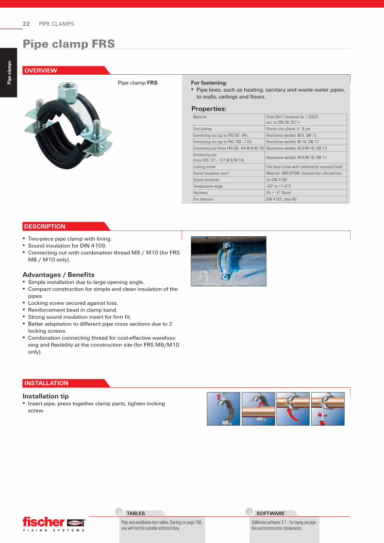
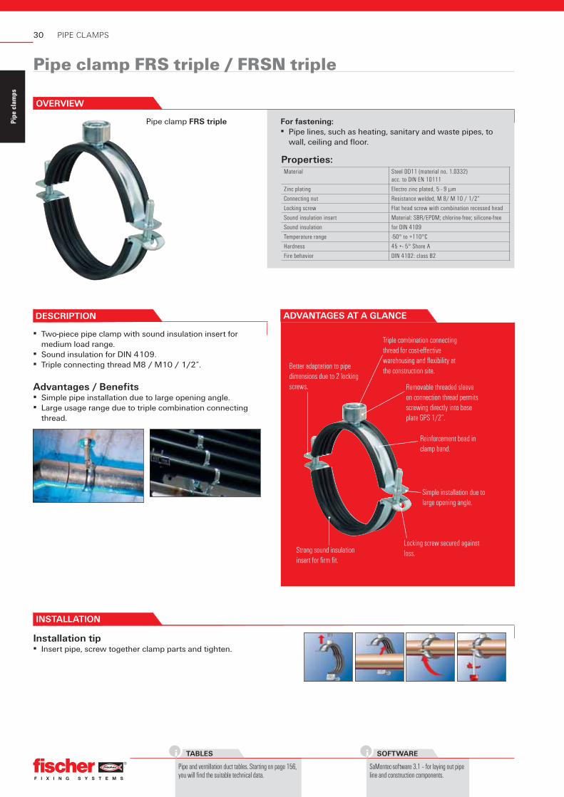
For fastening:▪ Pipe lines, such as heating, sanitary and waste water pipes,
to walls, ceilings and fl oors.
INSTALLATION
Installation tip▪ Insert pipe, press together clamp parts, engage locking
screw and tighten.
OVERVIEW
21
Pipe
cla
mps
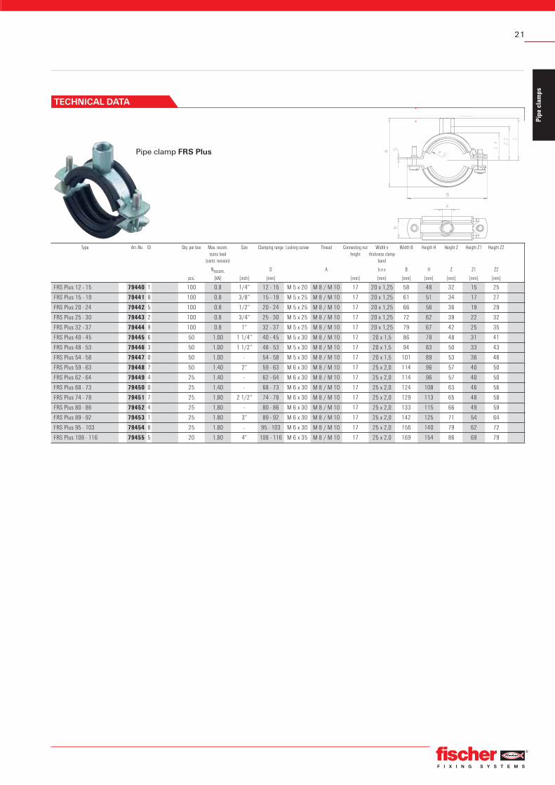
Pipe clamp FRS Plus
Type Art.-No. ID Qty. per box Max. recom. static load
(centr. tension)
Size Clamping range Locking screw Thread Connecting nut height
▪ Two-piece pipe clamp with lining.▪ Sound insulation for DIN 4109.▪ Connecting nut with combination thread M8 / M10 (for FRS
M8 / M10 only).
Advantages / Benefi ts▪ Simple installation due to large opening angle.▪ Compact construction for simple and clean insulation of the
pipes.▪ Locking screw secured against loss.▪ Reinforcement bead in clamp band.▪ Strong sound insulation insert for fi rm fi t.▪ Better adaptation to diff erent pipe cross sections due to 2
locking screws.▪ Combination connecting thread for cost-eff ective warehou-
sing and fl exibility at the construction site (for FRS M8/M10 only).
For fastening:▪ Pipe lines, such as heating, sanitary and waste water pipes,
to walls, ceilings and fl oors.
INSTALLATION
Installation tip▪ Insert pipe, press together clamp parts, tighten locking
screw.
OVERVIEW
23
Pipe
cla
mps
STAINLESS-STEEL
You will find products in stain-less-steel version starting on page 116.
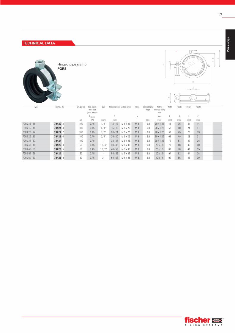
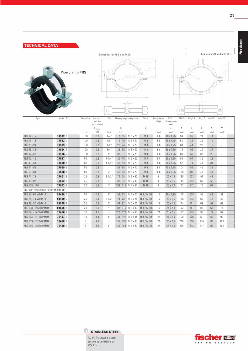
Pipe clamp FRS
Connecting nut M 8 resp. M 10 Combination thread M 8/M 10
Type Art.-No. ID Qty. per box Max. recom. static load
(centr. tension)
Size Clamping range Locking screw Thread Connecting nut height
Connecting nut (up to FRSH 59 - 63) Resistance welded, M 8, SW 13
Locking screw Flat head screw with combination recessed head
Sound insulation insert Material: silicone
Sound insulation for DIN 4109
Temperature range -50° to +220°C
Hardness 60 + - 5° Shore A
Fire behavior DIN 4102: class B2
PIPE CLAMPS
Silicone pipe clamp FRSH
DESCRIPTION
▪ Two-piece pipe clamp with high temperature resistant sound insulation insert without quick connect.
▪ Sound insulation for DIN 4109.
Advantages / Benefi ts▪ Simple installation due to large opening angle.▪ Locking screw secured against loss.▪ Reinforcement bead in clamp band.▪ Strong sound insulation insert for fi rm fi t.▪ Better adaptation to diff erent pipe cross sections due to 2
locking screws.▪ Use for steam up to max. +220°C.
For fastening:▪ Pipe lines with high temperatures up to +220°C, such as
heating, sanitary and waste water pipes, to wall, ceiling and fl oor.
INSTALLATION
Installation tip▪ Insert pipe, press together clamp parts, tighten locking
screws.
OVERVIEW
27
Pipe
cla
mps
DIAGRAMS
Starting on page 159, you will find the expansions of pipe lines.
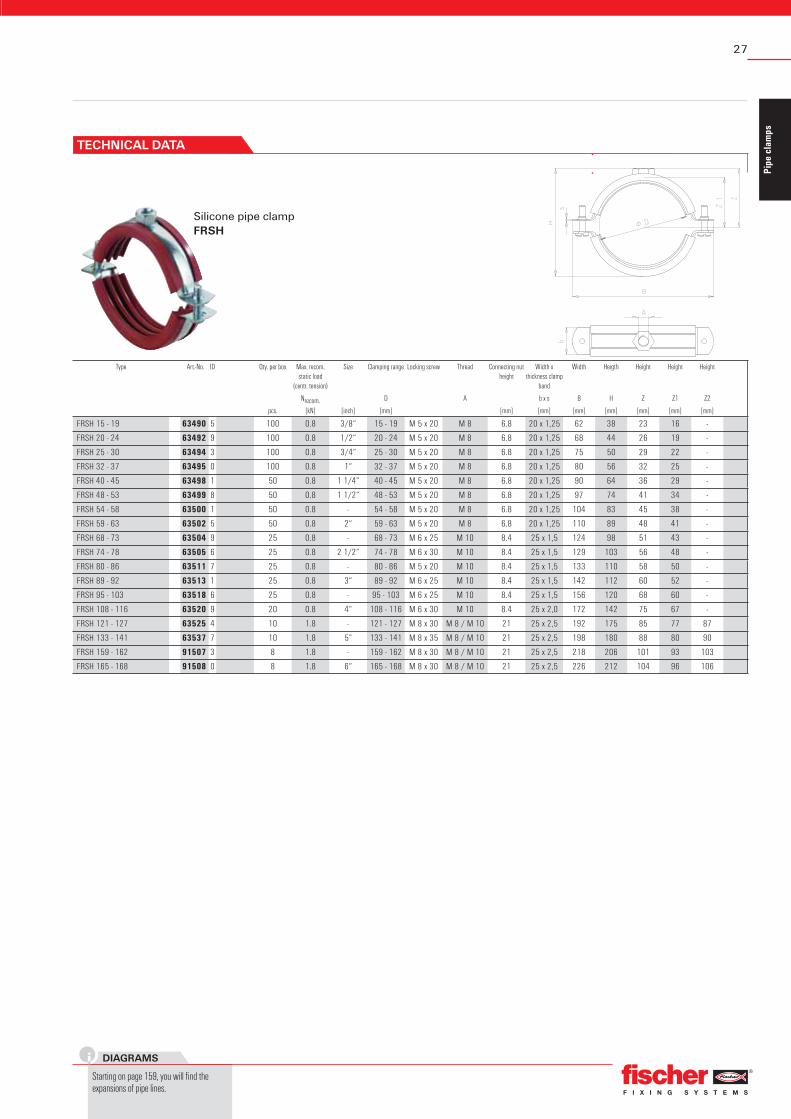
Silicone pipe clamp FRSH
Type Art.-No. ID Qty. per box Max. recom. static load
(centr. tension)
Size Clamping range Locking screw Thread Connecting nut height
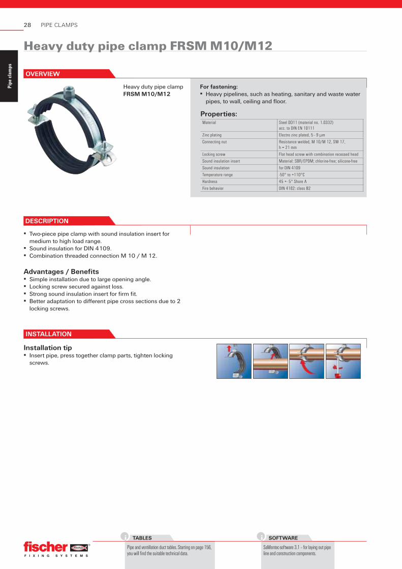
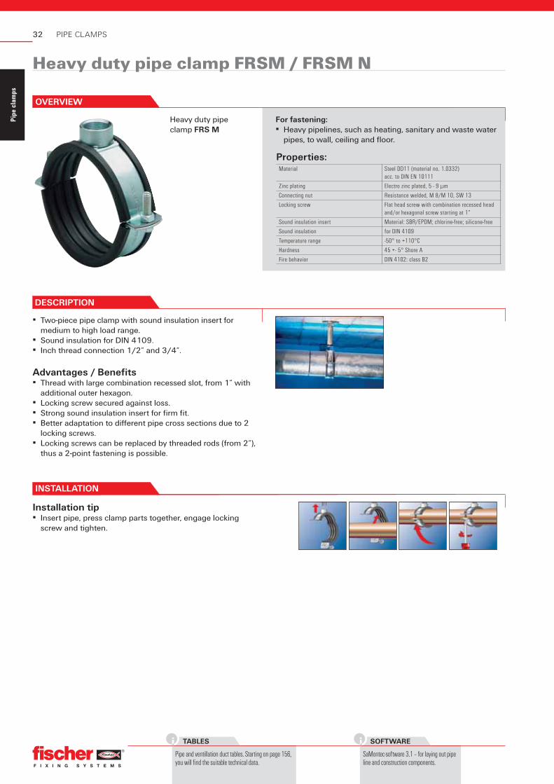
▪ Two-piece pipe clamp with sound insulation insert for medium to high load range.
▪ Sound insulation for DIN 4109.▪ Combination threaded connection M 10 / M 12.
Advantages / Benefi ts▪ Simple installation due to large opening angle.▪ Locking screw secured against loss.▪ Strong sound insulation insert for fi rm fi t.▪ Better adaptation to diff erent pipe cross sections due to 2
locking screws.
For fastening:▪ Heavy pipelines, such as heating, sanitary and waste water
pipes, to wall, ceiling and fl oor.
INSTALLATION
Installation tip▪ Insert pipe, press together clamp parts, tighten locking
screws.
OVERVIEW
29
Pipe
cla
mps
DIAGRAMS
Starting on page 159, you will find the expansions of pipe lines.
Heavy duty pipe clamp FRSM M10/M12
Type Art.-No. ID Qty. per box Size Clamping range Locking screw Thread Connecting nut height
▪ Two-piece pipe clamp with sound insulation insert for medium to high load range.
▪ Sound insulation for DIN 4109.▪ Inch thread connection 1/2” and 3/4”.
Advantages / Benefi ts▪ Thread with large combination recessed slot, from 1” with
additional outer hexagon.▪ Locking screw secured against loss.▪ Strong sound insulation insert for fi rm fi t.▪ Better adaptation to diff erent pipe cross sections due to 2
locking screws.▪ Locking screws can be replaced by threaded rods (from 2”),
thus a 2-point fastening is possible.
For fastening:▪ Heavy pipelines, such as heating, sanitary and waste water
pipes, to wall, ceiling and fl oor.
INSTALLATION
Installation tip▪ Insert pipe, press clamp parts together, engage locking
screw and tighten.
OVERVIEW
33
Pipe
cla
mps
DIAGRAMS
Starting on page 159, you will find the expansions of pipe lines.
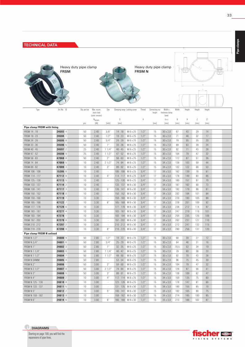
Heavy duty pipe clamp FRSM
Type Art.-No. ID Qty. per box Max. recom. static load
(centr. tension)
Size Clamping range Locking screw Thread Connecting nut height
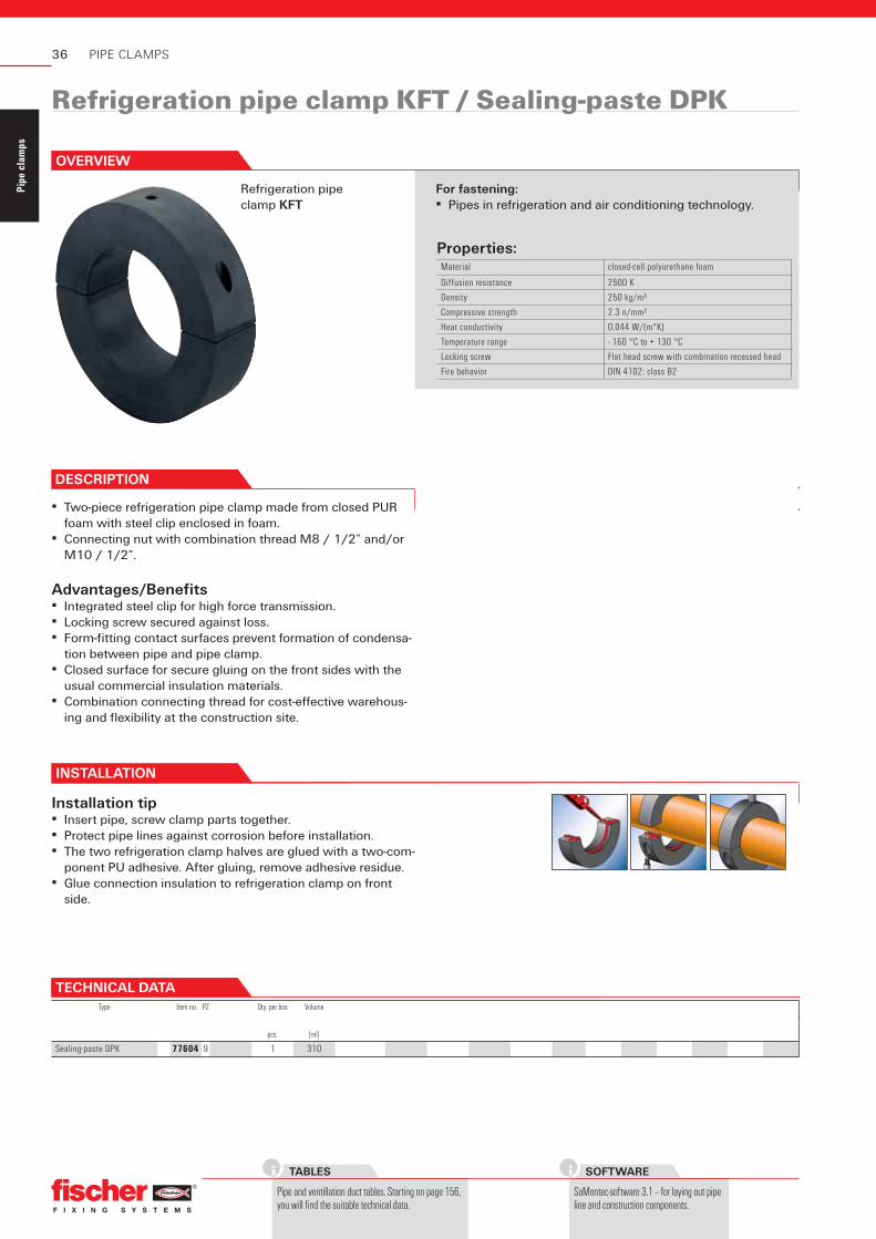
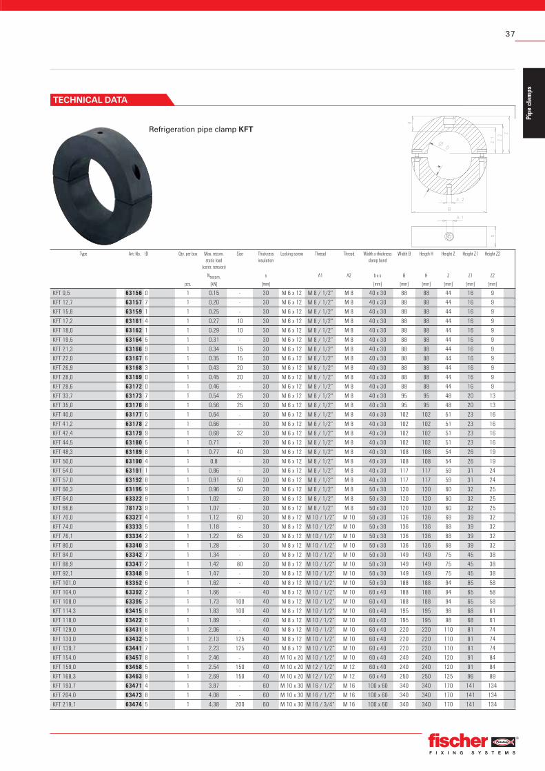
Advantages/Benefi ts▪ Integrated steel clip for high force transmission.▪ Locking screw secured against loss.▪ Form-fi tting contact surfaces prevent formation of condensa-
tion between pipe and pipe clamp.▪ Closed surface for secure gluing on the front sides with the
For fastening:▪ Pipes in refrigeration and air conditioning technology.
INSTALLATION
Installation tip▪ Insert pipe, screw clamp parts together.▪ Protect pipe lines against corrosion before installation.▪ The two refrigeration clamp halves are glued with a two-com-
ponent PU adhesive. After gluing, remove adhesive residue.▪ Glue connection insulation to refrigeration clamp on front
side.
OVERVIEW
TECHNICAL DATAType Item no. PZ Qty. per box Volume
pcs. [ml]
Sealing-paste DPK 77604 9 1 310
Refrigeration pipe clamp KFT / Sealing-paste DPK
37
Pipe
cla
mps
Refrigeration pipe clamp KFT
Type Art.-No. ID Qty. per box Max. recom. static load
(centr. tension)
Size Thicknessinsulation
Locking screw Thread Thread Width x thickness clamp band
Width B Heigth H Height Z Height Z1 Height Z2
Nrecom. s A1 A2 b x s B H Z Z1 Z2
pcs. [kN] [mm] [mm] [mm] [mm] [mm] [mm] [mm]
KFT 9,5 63156 0 1 0.15 - 30 M 6 x 12 M 8 / 1/2“ M 8 40 x 30 88 88 44 16 9
KFT 12,7 63157 7 1 0.20 - 30 M 6 x 12 M 8 / 1/2“ M 8 40 x 30 88 88 44 16 9
KFT 15,8 63159 1 1 0.25 - 30 M 6 x 12 M 8 / 1/2“ M 8 40 x 30 88 88 44 16 9
KFT 17,2 63161 4 1 0.27 10 30 M 6 x 12 M 8 / 1/2“ M 8 40 x 30 88 88 44 16 9
KFT 18,0 63162 1 1 0.29 10 30 M 6 x 12 M 8 / 1/2“ M 8 40 x 30 88 88 44 16 9
KFT 19,5 63164 5 1 0.31 - 30 M 6 x 12 M 8 / 1/2“ M 8 40 x 30 88 88 44 16 9
KFT 21,3 63166 9 1 0.34 15 30 M 6 x 12 M 8 / 1/2“ M 8 40 x 30 88 88 44 16 9
KFT 22,0 63167 6 1 0.35 15 30 M 6 x 12 M 8 / 1/2“ M 8 40 x 30 88 88 44 16 9
KFT 26,9 63168 3 1 0.43 20 30 M 6 x 12 M 8 / 1/2“ M 8 40 x 30 88 88 44 16 9
KFT 28,0 63169 0 1 0.45 20 30 M 6 x 12 M 8 / 1/2“ M 8 40 x 30 88 88 44 16 9
KFT 28,6 63172 0 1 0.46 - 30 M 6 x 12 M 8 / 1/2“ M 8 40 x 30 88 88 44 16 9
KFT 33,7 63173 7 1 0.54 25 30 M 6 x 12 M 8 / 1/2“ M 8 40 x 30 95 95 48 20 13
KFT 35,0 63176 8 1 0.56 25 30 M 6 x 12 M 8 / 1/2“ M 8 40 x 30 95 95 48 20 13
KFT 40,0 63177 5 1 0.64 - 30 M 6 x 12 M 8 / 1/2“ M 8 40 x 30 102 102 51 23 16
KFT 41,2 63178 2 1 0.66 - 30 M 6 x 12 M 8 / 1/2“ M 8 40 x 30 102 102 51 23 16
KFT 42,4 63179 9 1 0.68 32 30 M 6 x 12 M 8 / 1/2“ M 8 40 x 30 102 102 51 23 16
KFT 44,5 63180 5 1 0.71 - 30 M 6 x 12 M 8 / 1/2“ M 8 40 x 30 102 102 51 23 16
KFT 48,3 63189 8 1 0.77 40 30 M 6 x 12 M 8 / 1/2“ M 8 40 x 30 108 108 54 26 19
KFT 50,0 63190 4 1 0.8 - 30 M 6 x 12 M 8 / 1/2“ M 8 40 x 30 108 108 54 26 19
KFT 54,0 63191 1 1 0.86 - 30 M 6 x 12 M 8 / 1/2“ M 8 40 x 30 117 117 59 31 24
KFT 57,0 63192 8 1 0.91 50 30 M 6 x 12 M 8 / 1/2“ M 8 40 x 30 117 117 59 31 24
KFT 60,3 63195 9 1 0.96 50 30 M 6 x 12 M 8 / 1/2“ M 8 50 x 30 120 120 60 32 25
KFT 64,0 63322 9 1 1.02 - 30 M 6 x 12 M 8 / 1/2“ M 8 50 x 30 120 120 60 32 25
KFT 66,6 78173 9 1 1.07 - 30 M 6 x 12 M 8 / 1/2“ M 8 50 x 30 120 120 60 32 25
KFT 70,0 63327 4 1 1.12 60 30 M 8 x 12 M 10 / 1/2“ M 10 50 x 30 136 136 68 39 32
KFT 74,0 63333 5 1 1.18 - 30 M 8 x 12 M 10 / 1/2“ M 10 50 x 30 136 136 68 39 32
KFT 76,1 63334 2 1 1.22 65 30 M 8 x 12 M 10 / 1/2“ M 10 50 x 30 136 136 68 39 32
KFT 80,0 63340 3 1 1.28 - 30 M 8 x 12 M 10 / 1/2“ M 10 50 x 30 136 136 68 39 32
KFT 84,0 63342 7 1 1.34 - 30 M 8 x 12 M 10 / 1/2“ M 10 50 x 30 149 149 75 45 38
KFT 88,9 63347 2 1 1.42 80 30 M 8 x 12 M 10 / 1/2“ M 10 50 x 30 149 149 75 45 38
KFT 92,1 63348 9 1 1.47 - 30 M 8 x 12 M 10 / 1/2“ M 10 50 x 30 149 149 75 45 38
KFT 101,0 63352 6 1 1.62 - 40 M 8 x 12 M 10 / 1/2“ M 10 50 x 30 188 188 94 65 58
KFT 104,0 63392 2 1 1.66 - 40 M 8 x 12 M 10 / 1/2“ M 10 60 x 40 188 188 94 65 58
KFT 108,0 63395 3 1 1.73 100 40 M 8 x 12 M 10 / 1/2“ M 10 60 x 40 188 188 94 65 58
KFT 114,3 63415 8 1 1.83 100 40 M 8 x 12 M 10 / 1/2“ M 10 60 x 40 195 195 98 68 61
KFT 118,0 63422 6 1 1.89 - 40 M 8 x 12 M 10 / 1/2“ M 10 60 x 40 195 195 98 68 61
KFT 129,0 63431 8 1 2.06 - 40 M 8 x 12 M 10 / 1/2“ M 10 60 x 40 220 220 110 81 74
KFT 133,0 63432 5 1 2.13 125 40 M 8 x 12 M 10 / 1/2“ M 10 60 x 40 220 220 110 81 74
KFT 139,7 63441 7 1 2.23 125 40 M 8 x 12 M 10 / 1/2“ M 10 60 x 40 220 220 110 81 74
KFT 154,0 63457 8 1 2.46 - 40 M 10 x 20 M 10 / 1/2“ M 10 60 x 40 240 240 120 91 84
KFT 159,0 63458 5 1 2.54 150 40 M 10 x 20 M 12 / 1/2“ M 12 60 x 40 240 240 120 91 84
KFT 168,3 63463 9 1 2.69 150 40 M 10 x 20 M 12 / 1/2“ M 12 60 x 40 250 250 125 96 89
KFT 193,7 63471 4 1 3.87 - 60 M 10 x 30 M 16 / 1/2“ M 16 100 x 60 340 340 170 141 134
KFT 204,0 63473 8 1 4.08 - 60 M 10 x 30 M 16 / 1/2“ M 16 100 x 60 340 340 170 141 134
KFT 219,1 63474 5 1 4.38 200 60 M 10 x 30 M 16 / 3/4“ M 16 100 x 60 340 340 170 141 134
TECHNICAL DATA
38
Pipe
cla
mps
TABLES
Pipe and ventillation duct tables. Starting on page 156, you will find the suitable technical data.
SOFTWARE
SaMontec-software 3.1 – for laying out pipe line and construction components.
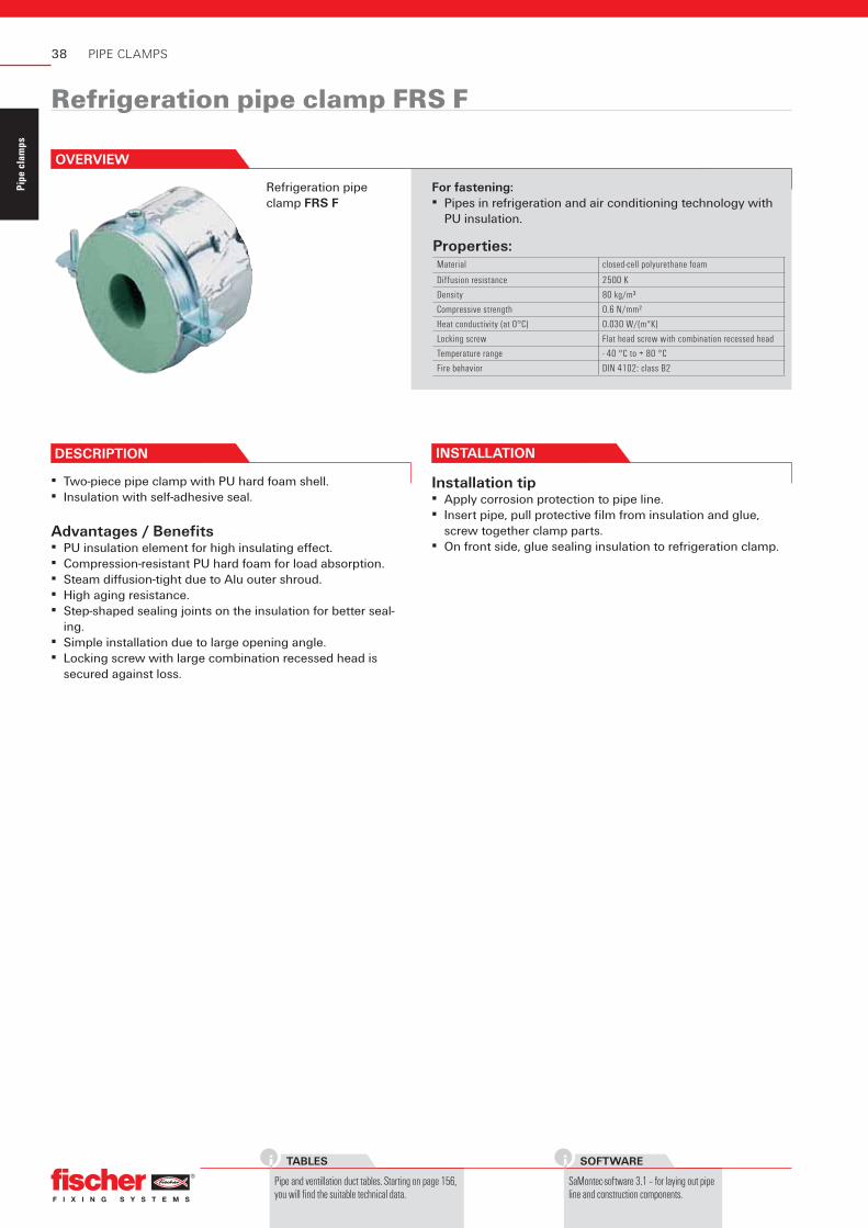
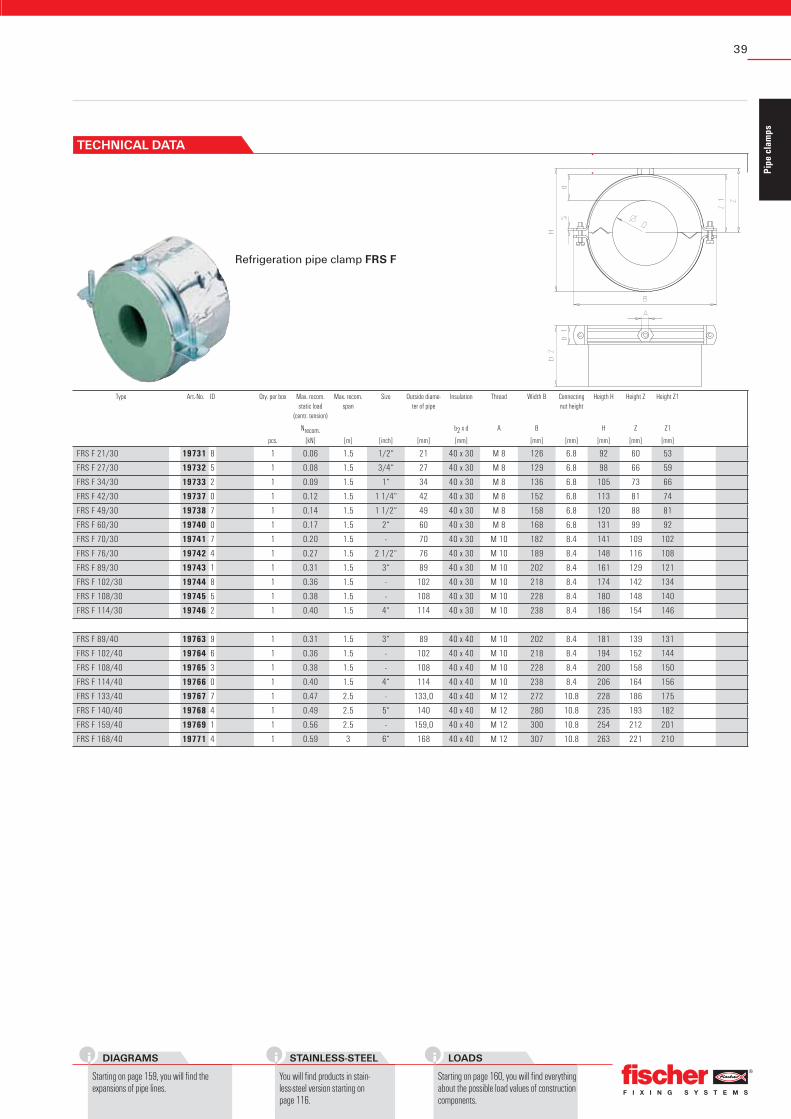
Refrigeration pipe clamp FRS F
DESCRIPTION
Properties:Material closed-cell polyurethane foam
Diffusion resistance 2500 K
Density 80 kg/m³
Compressive strength 0.6 N/mm²
Heat conductivity (at 0°C) 0.030 W/(m*K)
Locking screw Flat head screw with combination recessed head
Temperature range - 40 °C to + 80 °C
Fire behavior DIN 4102: class B2
PIPE CLAMPS
Refrigeration pipe clamp FRS F
▪ Two-piece pipe clamp with PU hard foam shell.▪ Insulation with self-adhesive seal.
Advantages / Benefi ts▪ PU insulation element for high insulating eff ect.▪ Compression-resistant PU hard foam for load absorption.▪ Steam diff usion-tight due to Alu outer shroud.▪ High aging resistance.▪ Step-shaped sealing joints on the insulation for better seal-
ing.▪ Simple installation due to large opening angle.▪ Locking screw with large combination recessed head is
secured against loss.
For fastening:▪ Pipes in refrigeration and air conditioning technology with
PU insulation.
INSTALLATION
Installation tip▪ Apply corrosion protection to pipe line.▪ Insert pipe, pull protective fi lm from insulation and glue,
screw together clamp parts.▪ On front side, glue sealing insulation to refrigeration clamp.
OVERVIEW
39
Pipe
cla
mps
LOADS
Starting on page 160, you will find everything about the possible load values of construction components.
DIAGRAMS
Starting on page 159, you will find the expansions of pipe lines.
Refrigeration pipe clamp FRS F
Type Art.-No. ID Qty. per box Max. recom. static load
FRS F 21/30 19731 8 1 0.06 1.5 1/2“ 21 40 x 30 M 8 126 6.8 92 60 53
FRS F 27/30 19732 5 1 0.08 1.5 3/4“ 27 40 x 30 M 8 129 6.8 98 66 59
FRS F 34/30 19733 2 1 0.09 1.5 1“ 34 40 x 30 M 8 136 6.8 105 73 66
FRS F 42/30 19737 0 1 0.12 1.5 1 1/4“ 42 40 x 30 M 8 152 6.8 113 81 74
FRS F 49/30 19738 7 1 0.14 1.5 1 1/2“ 49 40 x 30 M 8 158 6.8 120 88 81
FRS F 60/30 19740 0 1 0.17 1.5 2“ 60 40 x 30 M 8 168 6.8 131 99 92
FRS F 70/30 19741 7 1 0.20 1.5 - 70 40 x 30 M 10 182 8.4 141 109 102
FRS F 76/30 19742 4 1 0.27 1.5 2 1/2“ 76 40 x 30 M 10 189 8.4 148 116 108
FRS F 89/30 19743 1 1 0.31 1.5 3“ 89 40 x 30 M 10 202 8.4 161 129 121
FRS F 102/30 19744 8 1 0.36 1.5 - 102 40 x 30 M 10 218 8.4 174 142 134
FRS F 108/30 19745 5 1 0.38 1.5 - 108 40 x 30 M 10 228 8.4 180 148 140
FRS F 114/30 19746 2 1 0.40 1.5 4“ 114 40 x 30 M 10 238 8.4 186 154 146
FRS F 89/40 19763 9 1 0.31 1.5 3“ 89 40 x 40 M 10 202 8.4 181 139 131
FRS F 102/40 19764 6 1 0.36 1.5 - 102 40 x 40 M 10 218 8.4 194 152 144
FRS F 108/40 19765 3 1 0.38 1.5 - 108 40 x 40 M 10 228 8.4 200 158 150
FRS F 114/40 19766 0 1 0.40 1.5 4“ 114 40 x 40 M 10 238 8.4 206 164 156
FRS F 133/40 19767 7 1 0.47 2.5 - 133,0 40 x 40 M 12 272 10.8 228 186 175
FRS F 140/40 19768 4 1 0.49 2.5 5“ 140 40 x 40 M 12 280 10.8 235 193 182
FRS F 159/40 19769 1 1 0.56 2.5 - 159,0 40 x 40 M 12 300 10.8 254 212 201
FRS F 168/40 19771 4 1 0.59 3 6“ 168 40 x 40 M 12 307 10.8 263 221 210
TECHNICAL DATA
STAINLESS-STEEL
You will find products in stain-less-steel version starting on page 116.
40
Pipe
cla
mps
TABLES
Pipe and ventillation duct tables. Starting on page 156, you will find the suitable technical data.
SOFTWARE
SaMontec-software 3.1 – for laying out pipe line and construction components.
Refrigeration pipe clamp FRS K
Properties:Material closed-cell polyurethane foam
Diffusion resistance 7000 K
Density 250 kg/m³
Compressive strength 0.85 N/mm²
Heat conductivity (at 0°C) 0.036 W/(m*K)
Locking screw Flat head screw with combination recessed head
Temperature range - 45 °C to + 105 °C
Fire behavior DIN 4102: class B2
PIPE CLAMPS
Refrigerant pipe clamp FRS K
DESCRIPTION
▪ Two-piece pipe clamp, insulation made from elastomer rubber with PU hard foam shell.
▪ Insulation with self-adhesive seal.
Advantages / Benefi ts▪ PU insulation element for high insulating eff ect, coordinated
to standard insulation layer thicknesses.▪ Compression-resistant PU hard foam for load absorption.▪ High aging resistance.▪ Step-shaped sealing joints on the insulation for better seal-
ing.▪ Simple installation due to large opening angle.▪ Locking screw with large combination recessed head is
secured against loss.
For fastening:▪ Pipes in refrigeration and air conditioning technology with
insulation made from elastomer rubber.
INSTALLATION
Installation tip▪ Apply corrosion protection to pipe line.▪ Insert pipe, pull protective fi lm from insulation and glue,
screw together clamp parts.▪ On front side, glue sealing insulation to refrigeration clamp.
OVERVIEW
41
Pipe
cla
mps
DIAGRAMS
Starting on page 159, you will find the expansions of pipe lines.
Refrigeration pipe clamp FRS K
Type Art.-No. ID Qty. per box Max. recom. static load