Pipe Dream: An Out-of-Order, Speculative Processor Karthik Balakrishnan and Michal Karczmarek 6.884 Final Project Report May 12, 2005 1 Proposal For our 6.884 project we propose to design an SMIPS core. This is one of the standard projects. We will optimize the core by adding various components. We expect our CPU will require 8 cycles before the data enters the execution units. Our SMIPS core will be single-issue. Our basic design have the following specifications: • Single-issue processing • In-order execution • No branch prediction For our design exploration, we will experiment with the following possible enhancements: • Out-of-order execution • Branch history table • Branch target buffer • Speculative load-dependent instruction scheduling • Precise exception handling The following two sections will provide some detail as to the implementation of the basic design and design exploration methodologies. 1.1 Basic Design The basic design will be composed of following major modules, which will be discussed in the upcoming sections: 1. PC GEN 2. FETCH 3. DECODE 4. IPCF 5. RENAME 6. ROB 7. RREAD 8. EXEC 9. RETIRE 1
Transcript
Pipe Dream: An Out-of-Order, Speculative Processor
Karthik Balakrishnan and Michal Karczmarek
6.884 Final Project Report
May 12, 2005
1 Proposal
For our 6.884 project we propose to design an SMIPS core. This is one of the standard projects. Wewill optimize the core by adding various components. We expect our CPU will require 8 cycles beforethe data enters the execution units. Our SMIPS core will be single-issue. Our basic design have thefollowing specifications:
• Single-issue processing
• In-order execution
• No branch prediction
For our design exploration, we will experiment with the following possible enhancements:
The following two sections will provide some detail as to the implementation of the basic design anddesign exploration methodologies.
1.1 Basic Design
The basic design will be composed of following major modules, which will be discussed in the upcomingsections:
1. PC GEN
2. FETCH
3. DECODE
4. IPCF
5. RENAME
6. ROB
7. RREAD
8. EXEC
9. RETIRE
1
1.1.1 PC Generate
PC GEN generate a new PC on every cycle. In the basic version it will simply increment the old PCby 4.
1.1.2 Fetch
Fetch will interface with the outside memory module to fetch an instruction. It will wait patiently whilethe memory module makes up its mind about what instruction to return.
1.1.3 Decode
Decode will take the 32-bit SMIPS instruction and decode it into an opcode, information about whichregisters are being read/written and various other miscellaneous and useful information.
1.1.4 IPCF
IPCF is simply a file of 32-bit PC addresses for instructions. Any instruction that may need its PC inthe course of execution will store the PC in the IPCF and receive a tag. Before executing the instructionwill retrieve its PC. We originally added it to reduce the amount of storage necessary in the ROB.
1.1.5 Register Rename
Register rename will keep track of which architectural register is assigned to which physical register.
1.1.6 Re-order Buffer
The reorder buffer will not reorder. The ROB will schedule instructions, taking care to avoid write backconflicts. Load instructions will not be allocated a write-back slot, and will have to wait for an opening(which will come).
1.1.7 Register Read
RegRead will retrieve the values from the physical register file. It will also retrieve the PC from IPCFif the instruction has stored one there.
1.1.8 Execute
Execute will execute instructions and arbitrate results coming from the memory module.
1.1.9 Retire
Retire will take an executed instruction and handle its retirement. Usually that will mean updatingthe renaming table/RAT and/or freeing an entry in the IPCF. On a branch mispredict, though, it willnotify all the components of the CPU that they should do something special.
1.2 Design Exploration
During design exploration, we plan to enhance the system as previously described. The following sectionwill describe in further detail our proposed implementation for these enhancements.
1.2.1 Out-of-order Execution
To facilitate out-of-order execution, we plan to modify the re-order buffer to schedule instructions out oforder when possible. We will also change RETIRE to kill any instructions that have left the ROB, butshould not be executed (due to a branch mispredict or an exception). We will still retire all instructionsin order.
2
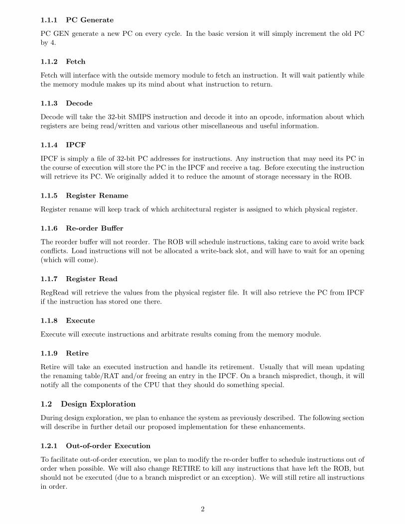
Figure 1: Basic Design data flow
1.2.2 Branch History Table
We will implement a standard BHT with a global history, as described in 6.823 slides. RETIRE willnotify the BHT of whether branches are resolved taken or not to facilitate the BHT’s learning.
1.2.3 Branch Target Buffer
We will implement a standard BTB, as described in 6.823 slides. RETIRE will notify the BTB of actualresolved branch targets to facilitate the BTB’s learning.
We will speculatively schedule instructions that require the return value of a load instruction. Sincethe load can result in a cache miss, we will have a mechanism to kill these speculative instructions ifnecessary.
1.3 Design Drawing
Figure 1 depicts the data flow for our basic design. This does not include any control signals. Note thatred dotted arrows depict FIFOs while solid black arrows depict function calls.
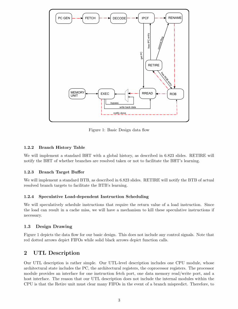
2 UTL Description
Our UTL description is rather simple. Our UTL-level description includes one CPU module, whosearchitectural state includes the PC, the architectural registers, the coprocessor registers. The processormodule provides an interface for one instruction fetch port, one data memory read/write port, and ahost interface. The reason that our UTL description does not include the internal modules within theCPU is that the Retire unit must clear many FIFOs in the event of a branch mispredict. Therefore, to
3
Figure 2: UTL depiction of our CPU
define a single module such as Execute as a single unit would not fully satisfy the specifications of aunit since a unit can only interact with other units by enqueuing to and dequeuing data from FIFOs.
Our CPU, however, does meet the specification for a UTL unit since it communications with instruc-tion and data memory through valid transactions. Figure 2 depicts in more detail the UTL descriptionfor our baseline design.
3 Design/Testing
Our major goal in testing will be to ensure that our design works correctly as a whole. We will write shortprograms which will test functionality of various instructions and features such as throwing exceptions.The testing will work similarly to what labs 1 and 2 did - simply observe the output of the tohost port.
We will also write an architectural simulator of the SMIPS CPU, and use it to verify that theinstructions we’re retiring write correct values to the register file and/or memory. This simulator will
not deal with exceptions or COP0 instructions. In order to use it correctly we will add a small moduleto the retire unit which will print to the screen which instruction is being retired, what its parameterswere and what value is written back as a result of executing this instruction. This type of testing willallow us to run larger programs through our processor and check the correctness of their execution veryquickly. The test rig will be able to report which instruction executed incorrectly, making debuggingmuch easier.1
1May 11, 2005: We did not find a need for such a complex testing strategy. In reality, we found that simply inspecting
traces of execution and eyeballing the source code was sufficient to solve our problems fairly quickly.
4
PC GEN FETCH DECODE IPCF RENAME
ROBRREADEXEC
RETIRE
copy
RAT
ove
r
clea
r all
next instr is in BDS
(if branch mispredict)
fetch BDS if branch mispredict
fetch from branch target / exception handlerclear all
notify if
exceptio
n in BDS
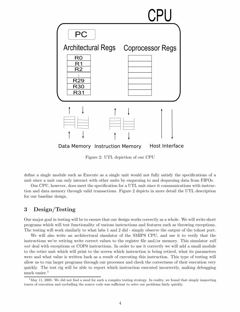
Figure 3: Handling of Branch Mispredict and a regular Synchronous Exception
4 Basic Micro-architectural description
Figure 3 shows our plan for processing branch mispredictions and exceptions. The basic data flow hasalready been shown in Figure 1.
Below we discuss the functions and interfaces each module uses.
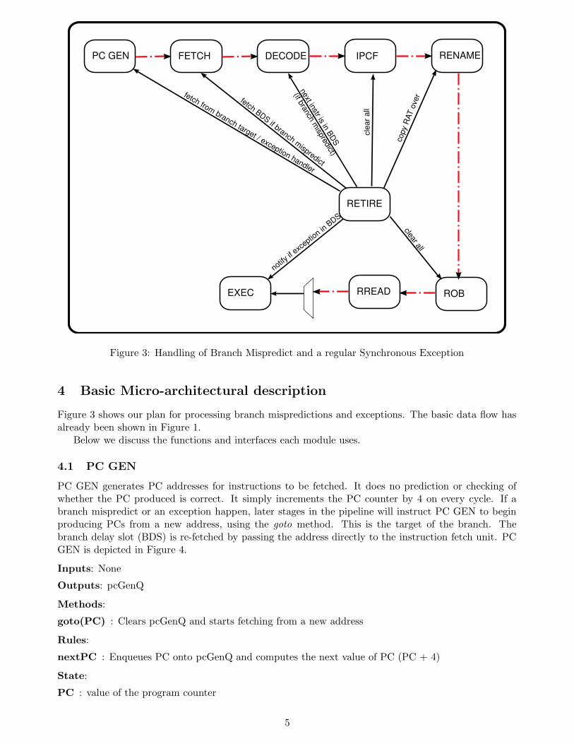
4.1 PC GEN
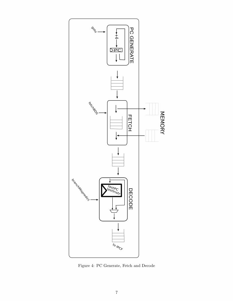
PC GEN generates PC addresses for instructions to be fetched. It does no prediction or checking ofwhether the PC produced is correct. It simply increments the PC counter by 4 on every cycle. If abranch mispredict or an exception happen, later stages in the pipeline will instruct PC GEN to beginproducing PCs from a new address, using the goto method. This is the target of the branch. Thebranch delay slot (BDS) is re-fetched by passing the address directly to the instruction fetch unit. PCGEN is depicted in Figure 4.
Inputs: None
Outputs: pcGenQ
Methods:
goto(PC) : Clears pcGenQ and starts fetching from a new address
Rules:
nextPC : Enqueues PC onto pcGenQ and computes the next value of PC (PC + 4)
State:
PC : value of the program counter
5
4.2 FETCH
Fetch sends an address of an instruction to the memory system and awaits the answer. Fetch canpipeline instructions fetched by putting the addresses of oustanding fetches on the instrReadPCWaitQFIFO. Fetch assumes that requests will come back in order from the memory. If a branch mispredict oran exception happen, Fetch is notified through the fetchBDS method. When that happens, Fetch stopssending instruction fetch requests to memory, waits for all outstanding requests to complete (indicatedby instrReadPCWaitQ being empty), and starts fetching instructions, first from the BDS, and laterfrom addresses in the pcGenQ. Fetch is depicted in Figure 4.
Inputs: pcGenQ
Outputs: fetchQ
Methods:
getInstrAddr () : Returns the address of the next instruction to fetch This is an exteranlly visible
function.
putInstr (instruction) : Receives the fetched instruction This is an exteranlly visible function.
fetchBDS (bdsAddr) : Marks all outstanding instruction fetches as invalid and clears fetchQ. Anyoutstanding instruction fetches will be silently processed, but not put in fetchQ. Will startfetching from bdsAddr.
Rules:
finishFetchBDS : Fires when the read PC queue is empty and changes the status to fetch the BDS
State:
instrReadPCWaitQ : internal buffer that holds values of PCs to be fetched
bdsAddr : contains the value of the BDS address if an instruction has a BDS
status : contains the status of the fetch unit - whether it should fetch normally, wait for the read PCqueue to empty, or fetch the branch delay slot
4.3 DECODE
Decode receives an instruction in raw format (a 32 bit integer) and decodes it into an opcode, sourceand destination register indexes and the immediate value. Decode also indicates whether the instructionis in the branch delay slot, by inspecting the opcode of the last instruction it decoded. On a branchmispredict, Decode assumes that the next instruction was a “J”. On an exception, previous instructionis set to InvalidException. Decode also indicates if an instruction needs to know its PC at executiontime. Instructions that need to know their PC include all jumps and branches, and any instruction thatcan cause an exception. Decode is depicted in Figure 4.
Inputs: fetchQ
Outputs: decodeQ
Methods:
branchMispredict() : clear decodeQ, reset DECODE and force next instruction to be decoded as ifit were in the BDS.
Rules:
decodeInstr : Obtains an instruction from fetchQ, appropriately decodes it, and places the resultonto decodeQ
State:
lastInstr : Stores the opcode of the last instruction decoded
6
Figure 4: PC Generate, Fetch and Decode
7
4.4 IPCF
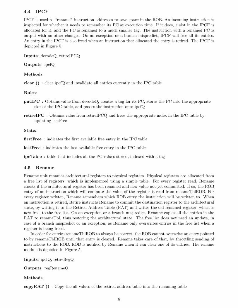
IPCF is used to “rename” instruction addresses to save space in the ROB. An incoming instruction isinspected for whether it needs to remember its PC at execution time. If it does, a slot in the IPCF isallocated for it, and the PC is renamed to a much smaller tag. The instruction with a renamed PC isoutput with no other changes. On an exception or a branch mispredict, IPCF will free all its entries.An entry in the IPCF is also freed when an instruction that allocated the entry is retired. The IPCF isdepicted in Figure 5.
Inputs: decodeQ, retireIPCQ
Outputs: ipcfQ
Methods:
clear () : clear ipcfQ and invalidate all entries currently in the IPC table.
Rules:
putIPC : Obtains value from decodeQ, creates a tag for its PC, stores the PC into the appropriateslot of the IPC table, and passes the instruction onto ipcfQ
retireIPC : Obtains value from retireIPCQ and frees the appropriate index in the IPC table byupdating lastFree
State:
firstFree : indicates the first available free entry in the IPC table
lastFree : indicates the last available free entry in the IPC table
ipcTable : table that includes all the PC values stored, indexed with a tag
4.5 Rename
Rename unit renames architectural registers to physical registers. Physical registers are allocated froma free list of registers, which is implemented using a simple table. For every register read, Renamechecks if the architectural register has been renamed and new value not yet committed. If so, the ROBentry of an instruction which will compute the value of the register is read from renameTblROB. Forevery register written, Rename remembers which ROB entry the instruction will be written to. Whenan instruction is retired, Retire instructs Rename to commit the destination register to the architecturalstate, by writing it to the Retired Address Table (RAT) and writes the old renamed register, which isnow free, to the free list. On an exception or a branch mispredict, Rename copies all the entries in theRAT to renameTbl, thus restoring the architectural state. The free list does not need an update, incase of a branch mispredict or an exception, as Rename only overwrites entries in the free list when aregister is being freed.
In order for entries renameTblROB to always be correct, the ROB cannot overwrite an entry pointedto by renameTblROB until that entry is cleared. Rename takes care of that, by throttling sending ofinstructions to the ROB. ROB is notified by Rename when it can clear one of its entries. The renamemodule is depicted in Figure 5.
Inputs: ipcfQ, retireRegQ
Outputs: regRenameQ
Methods:
copyRAT () : Copy the all values of the retired address table into the renaming table
8
Rules:
writeRenamedReg : Only needed because we use RWires to be able to simultaneously write twodifferent entries in renameTbl
renameReg : Renames the source and destination registers.
retireReg : Commits a renamed register to the architectural state.
State:
renameTbl : register rename table in which each entry consists of a renamed register
rat : retired address table containing values of committed registers for each architectural register
renameTblROB : table of ROB indexes to indicate which instruction is computing the value ofwhich register.
freeList : list of available physical registers
firstFree : index into freeList of first available physical register
lastFree : index into freeList of last available physical register
firstFreeROBIndx : next free slot in the ROB
firstBusyROBEntry : index of the oldest instruction in the ROB
4.6 ROB
The ROB acts as both a reorder buffer and a write-back buffer. An instruction entering the ROB checksinstructions which compute its operands to see if they’ve already been dispatched. If they have, thenthe operands are assumed to be valid. The instruction is now ready to enter the ROB.
On every cycle, the ROB attempts to schedule an instruction. Instructions are scheduled in-orderand non-speculatively. That means, that any instruction that can potentially change the control flow ofthe program stops the scheduler from dispatching subsequent instructions until it’s been written back.The instruction to be dispatched is pointed to by undispatchedROBEntry. The destination registerof the dispatched instruction is broadcast to all the entries in the ROB. If any instruction uses thesoon-to-be valid register, it updates it as a valid source register.
An instruction returning from the Execute unit carries an execution code, which is written back tothe ROB. This code indicates to the scheduler and the write back rule whether the following instructioncan be dispatched, or if a new stream of instructions need to be fetched. If the code is not “OK”, thePC of the instruction is saved.
Once an instruction has been written back, it can be sent to the Retire unit. Instructions are retiredin-order. If the instruction came back with a non-OK execution code, its PC will be sent to Retire aswell.
Inputs: renameQ, doneQ
Outputs: robQ, retireDataQ
Methods:
clear() : Clears the ROB, resetting the values of firstFreeROBEntry, firstBusyROBEntry,undispatchedROBEntry, and firstNonRetiredROBEntry. Also resets schedState to schedule.
Rules:
9
Figure 5: IPCF and Register Rename
10
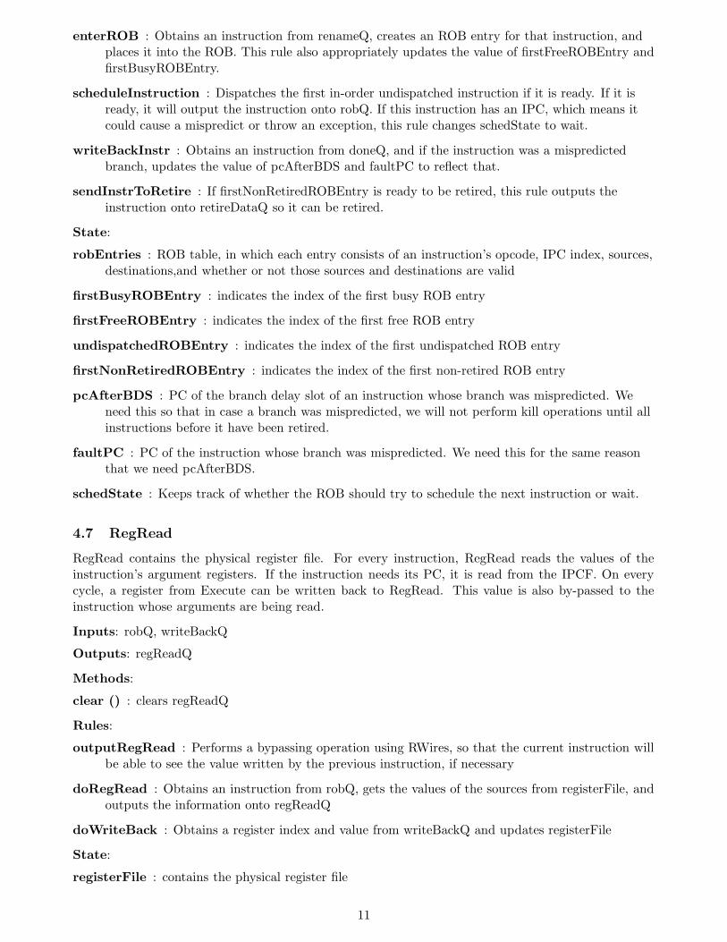
enterROB : Obtains an instruction from renameQ, creates an ROB entry for that instruction, andplaces it into the ROB. This rule also appropriately updates the value of firstFreeROBEntry andfirstBusyROBEntry.
scheduleInstruction : Dispatches the first in-order undispatched instruction if it is ready. If it isready, it will output the instruction onto robQ. If this instruction has an IPC, which means itcould cause a mispredict or throw an exception, this rule changes schedState to wait.
writeBackInstr : Obtains an instruction from doneQ, and if the instruction was a mispredictedbranch, updates the value of pcAfterBDS and faultPC to reflect that.
sendInstrToRetire : If firstNonRetiredROBEntry is ready to be retired, this rule outputs theinstruction onto retireDataQ so it can be retired.
State:
robEntries : ROB table, in which each entry consists of an instruction’s opcode, IPC index, sources,destinations,and whether or not those sources and destinations are valid
firstBusyROBEntry : indicates the index of the first busy ROB entry
firstFreeROBEntry : indicates the index of the first free ROB entry
undispatchedROBEntry : indicates the index of the first undispatched ROB entry
firstNonRetiredROBEntry : indicates the index of the first non-retired ROB entry
pcAfterBDS : PC of the branch delay slot of an instruction whose branch was mispredicted. Weneed this so that in case a branch was mispredicted, we will not perform kill operations until allinstructions before it have been retired.
faultPC : PC of the instruction whose branch was mispredicted. We need this for the same reasonthat we need pcAfterBDS.
schedState : Keeps track of whether the ROB should try to schedule the next instruction or wait.
4.7 RegRead
RegRead contains the physical register file. For every instruction, RegRead reads the values of theinstruction’s argument registers. If the instruction needs its PC, it is read from the IPCF. On everycycle, a register from Execute can be written back to RegRead. This value is also by-passed to theinstruction whose arguments are being read.
Inputs: robQ, writeBackQ
Outputs: regReadQ
Methods:
clear () : clears regReadQ
Rules:
outputRegRead : Performs a bypassing operation using RWires, so that the current instruction willbe able to see the value written by the previous instruction, if necessary
doRegRead : Obtains an instruction from robQ, gets the values of the sources from registerFile, andoutputs the information onto regReadQ
doWriteBack : Obtains a register index and value from writeBackQ and updates registerFile
State:
registerFile : contains the physical register file
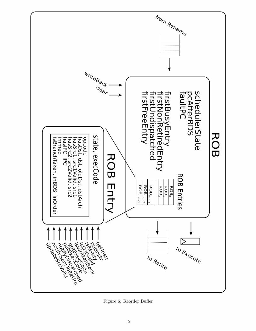
11
Figure 6: Reorder Buffer
12
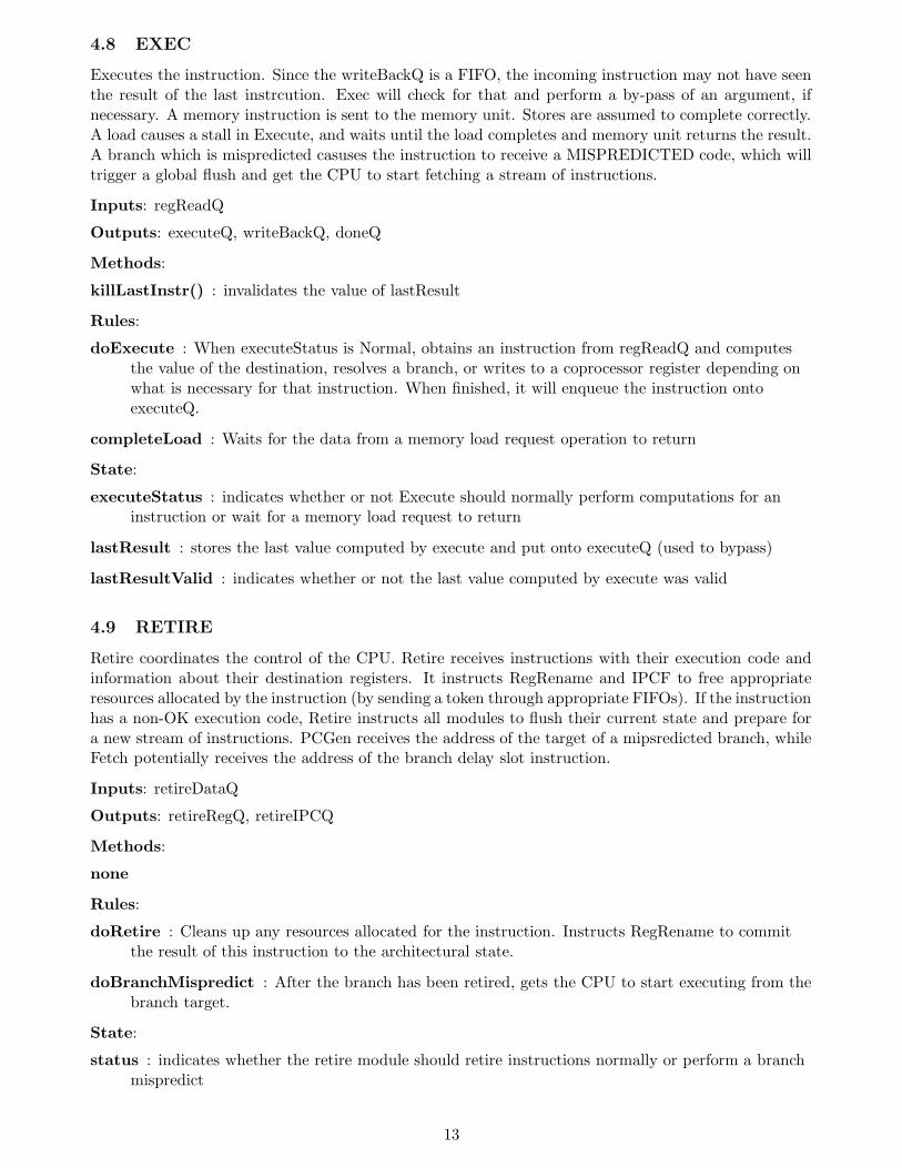
4.8 EXEC
Executes the instruction. Since the writeBackQ is a FIFO, the incoming instruction may not have seenthe result of the last instrcution. Exec will check for that and perform a by-pass of an argument, ifnecessary. A memory instruction is sent to the memory unit. Stores are assumed to complete correctly.A load causes a stall in Execute, and waits until the load completes and memory unit returns the result.A branch which is mispredicted casuses the instruction to receive a MISPREDICTED code, which willtrigger a global flush and get the CPU to start fetching a stream of instructions.
Inputs: regReadQ
Outputs: executeQ, writeBackQ, doneQ
Methods:
killLastInstr() : invalidates the value of lastResult
Rules:
doExecute : When executeStatus is Normal, obtains an instruction from regReadQ and computesthe value of the destination, resolves a branch, or writes to a coprocessor register depending onwhat is necessary for that instruction. When finished, it will enqueue the instruction ontoexecuteQ.
completeLoad : Waits for the data from a memory load request operation to return
State:
executeStatus : indicates whether or not Execute should normally perform computations for aninstruction or wait for a memory load request to return
lastResult : stores the last value computed by execute and put onto executeQ (used to bypass)
lastResultValid : indicates whether or not the last value computed by execute was valid
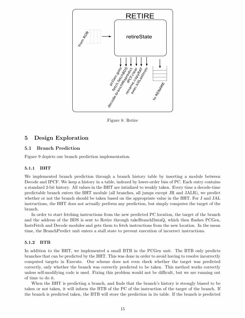
4.9 RETIRE
Retire coordinates the control of the CPU. Retire receives instructions with their execution code andinformation about their destination registers. It instructs RegRename and IPCF to free appropriateresources allocated by the instruction (by sending a token through appropriate FIFOs). If the instructionhas a non-OK execution code, Retire instructs all modules to flush their current state and prepare fora new stream of instructions. PCGen receives the address of the target of a mipsredicted branch, whileFetch potentially receives the address of the branch delay slot instruction.
Inputs: retireDataQ
Outputs: retireRegQ, retireIPCQ
Methods:
none
Rules:
doRetire : Cleans up any resources allocated for the instruction. Instructs RegRename to committhe result of this instruction to the architectural state.
doBranchMispredict : After the branch has been retired, gets the CPU to start executing from thebranch target.
State:
status : indicates whether the retire module should retire instructions normally or perform a branchmispredict
13
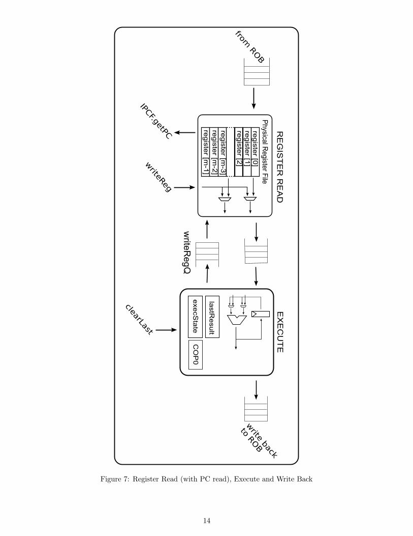
Figure 7: Register Read (with PC read), Execute and Write Back
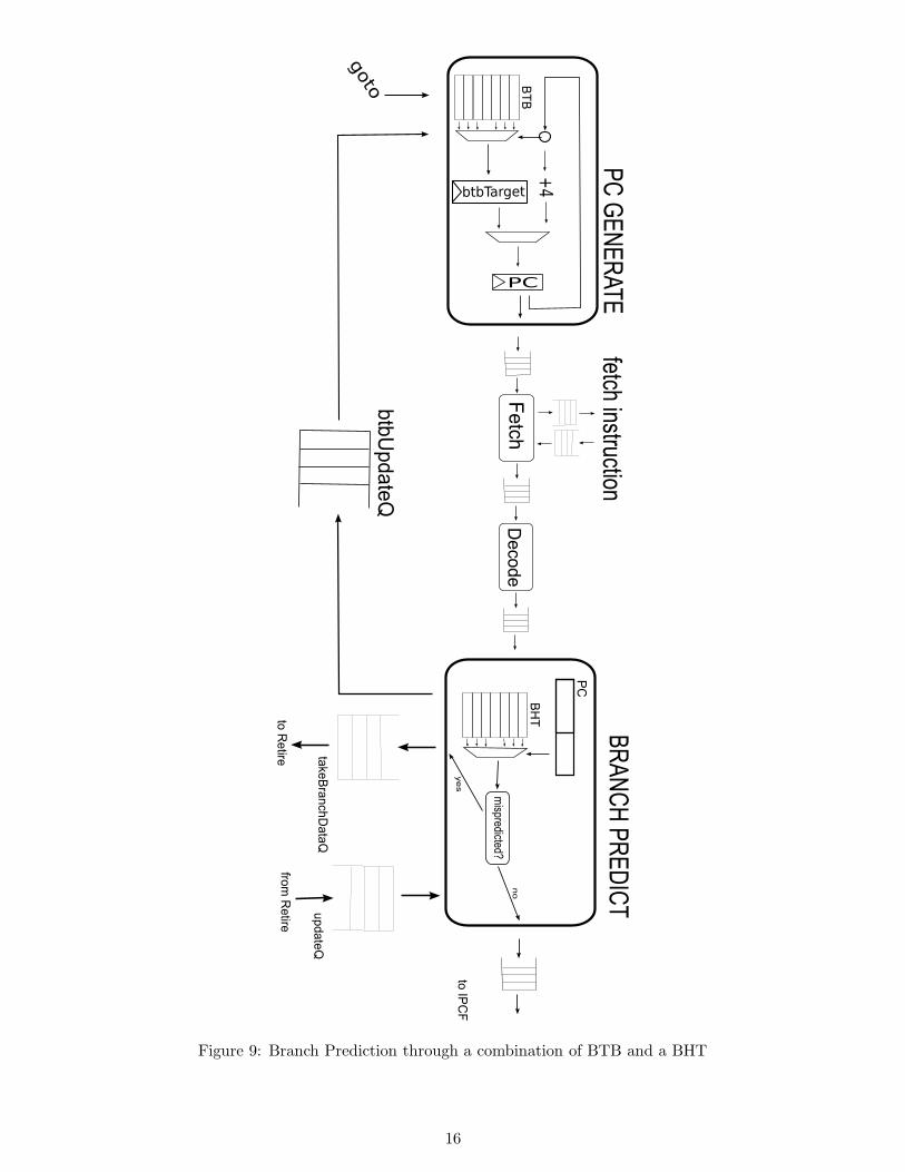
We implemented branch prediction through a branch history table by inserting a module betweenDecode and IPCF. We keep a history in a table, indexed by lower-order biss of PC. Each entry containsa standard 2-bit history. All values in the BHT are intialized to weakly taken. Every time a decode-timepredictable branch enters the BHT module (all branches, all jumps except JR and JALR), we predictwhether or not the branch should be taken based on the appropriate value in the BHT. For J and JALinstructions, the BHT does not actually perform any prediction, but simply computes the target of thebranch.
In order to start fetching instructions from the new predicted PC location, the target of the branchand the address of the BDS is sent to Retire through takeBranchDataQ, which then flushes PCGen,InstrFetch and Decode modules and gets them to fetch instructions from the new location. In the meantime, the BranchPredict unit enters a stall state to prevent execution of incorrect instructions.
5.1.2 BTB
In addition to the BHT, we implemented a small BTB in the PCGen unit. The BTB only predictsbranches that can be predicted by the BHT. This was done in order to avoid having to resolve incorrectlycomputed targets in Execute. Our scheme does not even check whether the target was predictedcorrectly, only whether the branch was correctly predicted to be taken. This method works correctlyunless self-modifying code is used. Fixing this problem would not be difficult, but we are running outof time to do it.
When the BHT is predicting a branch, and finds that the branch’s history is strongly biased to betaken or not taken, it will inform the BTB of the PC of the instruction of the target of the branch. Ifthe branch is predicted taken, the BTB will store the prediction in its table. If the branch is predicted
15
Figure 9: Branch Prediction through a combination of BTB and a BHT
16
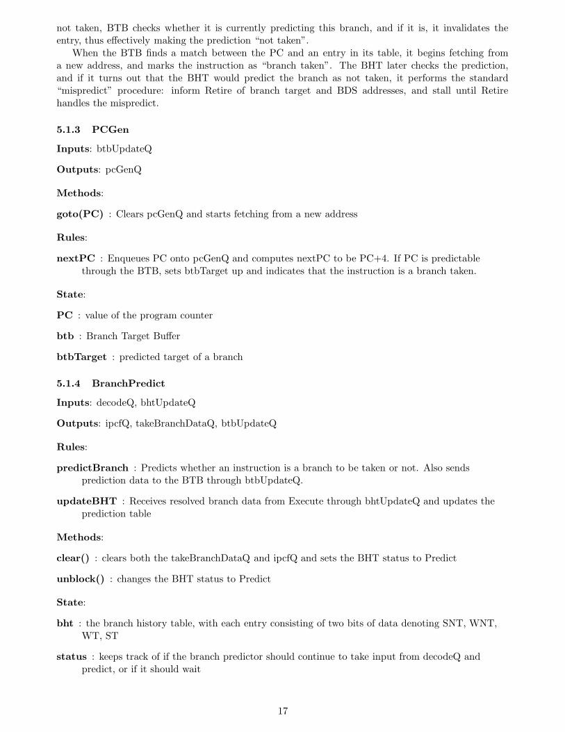
not taken, BTB checks whether it is currently predicting this branch, and if it is, it invalidates theentry, thus effectively making the prediction “not taken”.
When the BTB finds a match between the PC and an entry in its table, it begins fetching froma new address, and marks the instruction as “branch taken”. The BHT later checks the prediction,and if it turns out that the BHT would predict the branch as not taken, it performs the standard“mispredict” procedure: inform Retire of branch target and BDS addresses, and stall until Retirehandles the mispredict.
5.1.3 PCGen
Inputs: btbUpdateQ
Outputs: pcGenQ
Methods:
goto(PC) : Clears pcGenQ and starts fetching from a new address
Rules:
nextPC : Enqueues PC onto pcGenQ and computes nextPC to be PC+4. If PC is predictablethrough the BTB, sets btbTarget up and indicates that the instruction is a branch taken.
State:
PC : value of the program counter
btb : Branch Target Buffer
btbTarget : predicted target of a branch
5.1.4 BranchPredict
Inputs: decodeQ, bhtUpdateQ
Outputs: ipcfQ, takeBranchDataQ, btbUpdateQ
Rules:
predictBranch : Predicts whether an instruction is a branch to be taken or not. Also sendsprediction data to the BTB through btbUpdateQ.
updateBHT : Receives resolved branch data from Execute through bhtUpdateQ and updates theprediction table
Methods:
clear() : clears both the takeBranchDataQ and ipcfQ and sets the BHT status to Predict
unblock() : changes the BHT status to Predict
State:
bht : the branch history table, with each entry consisting of two bits of data denoting SNT, WNT,WT, ST
status : keeps track of if the branch predictor should continue to take input from decodeQ andpredict, or if it should wait
17
5.2 Out-of-Order Execution
In our basic design, we had created a re-order buffer. Much of the total design was ready for out-of-orderexecution, but our scheduler was not able to schedule instructionsout of order. This part of our designexploration introduced a very simple out-of-order scheduler to allow us to leverage the main advantageof our design. Since much of the rest of our design was out-of-order ready, we did not have to make anychanges to any interfaces or modules. All changes were internal to the ROB module.
The Out-of-order scheduler uses a simple, but slow algorithm to schedule an instruction. All theROB entries are walked from top to bottom. Each entry is read and inspected for whether it is a validinstruction (within the execution window described by firstBusyROBEntry and firstFreeROBEntry),whether it is ready, needs to execute in order and if it is a barrier. Even though our CPU is single-issue, the scheduler schedules two instructions at a time: one in-order, and one out of order. Thereason for this is that we traverse our ROB entries physically from top to bottom, rather than iteratingstarting at firstBusyROBEntry and going down. Since the ROB is a circular buffer, it is possible thatinstructions with smaller ROB indexes are actually younger than instructions with larger ROB indexes.Thus it is possible that an in-order instruction that “looks” ready to dispatch will be blocked by aninstruction found later in the ROB. Finally, the scheduler keeps track of how many memory instructionsare outstanding, and will not schedule a memory instruction if a set limit has been reached.
In order to reduce the amount of changes necessary for our design to work, we also changed theDecode module to indicate that store instructions are barriers. This means that a store instruction willblock execution of the program until all preceding instructions have executed correctly. This means thatwe do not need extra communication between the ROB or Retire and the memory unit to indicate whena store is ready to be committed to memory. We also set the limit of number of memory instructionsallowed to be in flight at a time to 1.
With those changes, our microprocessor was able to correctly pass all the tests and benchmarks.The performance was not great, but there was a marked improvement between an in-order version andan out-of-order version. Note, that the small changes to the design dealing with memory instructionswere made outside of the instruction scheduler. Once we had a better memory subsystem ready, we didnot have to change the scheduler again to take advantage of the new functionality.
Unfortunately, BSC was not able to compile our design with the ROB bigger than 12 entries, whichmeans we were not able to take full-advantage of the out-of-order capability, as even smallest loops(vvadd) require approximately 10 instructions. This means that our CPU was never able to effectivelyhide all memory access latency in the system. Our most up-to-date memory unit requires at least 3cycles to complete a load, plus the actual latency of the memory (one cycle in our test harness).
It would be an interesting design exploration to change the scheduling algorithm to schedule instruc-tions using a tree. It would probably give our system a big performance boost by reducing the cycletime, as the scheduler is always very near the top of list of critical paths in a laid-out chip.
5.3 Memory Unit
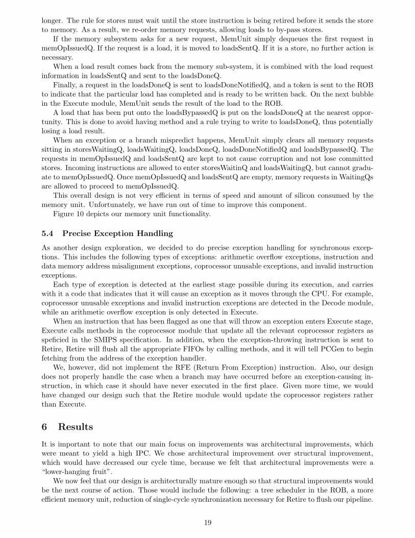
Surprisingly, the memory unit turned out to be the single most difficult part of the design. After severalattempts with more complicated, but also more efficient designs, we finally settled on a design that usesa lot of FIFOs to shuttle memory requests from one state to the next. Our current design employs sixseparate main FIFOs: storesWaitingQ, loadsWaitingQ, memOpIssuedQ, loadsSentQ, loadsDoneQ andloadsDoneNotifiedQ. In addition, we also have a storesOutstanding vector which remembers recent storeoperations and a loadsBypassedQ which we use to by-pass the memory system when a load accesses anaddress of a remembered store.
When a memory request arrives to the memory unit, it is classified as either a load or a store. A storeis entered onto storesWaitingQ and entered into the storesOutstanding vector. If the storesOutstandingvector is full, we shift it up, to make space for the new store. If the request is a load, we check if itmatches a remembered store in storesOustanding. If it does, we retrieve the value stored at the addressand put the resultinto loadsBypassedQ. If it does not, we put the load onto a loadsWaitingQ.
MemUnit has two rules that graduate memory requests into the memOpIssuedQ queue, one forloads, and one for stores. The rule for loads has been given priority, because loads are assumed to take
18
longer. The rule for stores must wait until the store instruction is being retired before it sends the storeto memory. As a result, we re-order memory requests, allowing loads to by-pass stores.
If the memory subsystem asks for a new request, MemUnit simply dequeues the first request inmemOpIssuedQ. If the request is a load, it is moved to loadsSentQ. If it is a store, no further action isnecessary.
When a load result comes back from the memory sub-system, it is combined with the load requestinformation in loadsSentQ and sent to the loadsDoneQ.
Finally, a request in the loadsDoneQ is sent to loadsDoneNotifiedQ, and a token is sent to the ROBto indicate that the particular load has completed and is ready to be written back. On the next bubblein the Execute module, MemUnit sends the result of the load to the ROB.
A load that has been put onto the loadsBypassedQ is put on the loadsDoneQ at the nearest oppor-tunity. This is done to avoid having method and a rule trying to write to loadsDoneQ, thus potentiallylosing a load result.
When an exception or a branch mispredict happens, MemUnit simply clears all memory requestssitting in storesWaitingQ, loadsWaitingQ, loadsDoneQ, loadsDoneNotifiedQ and loadsBypassedQ. Therequests in memOpIssuedQ and loadsSentQ are kept to not cause corruption and not lose committedstores. Incoming instructions are allowed to enter storesWaitinQ and loadsWaitingQ, but cannot gradu-ate to memOpIssuedQ. Once memOpIssuedQ and loadsSentQ are empty, memory requests in WaitingQsare allowed to proceed to memOpIssuedQ.
This overall design is not very efficient in terms of speed and amount of silicon consumed by thememory unit. Unfortunately, we have run out of time to improve this component.
Figure 10 depicts our memory unit functionality.
5.4 Precise Exception Handling
As another design exploration, we decided to do precise exception handling for synchronous excep-tions. This includes the following types of exceptions: arithmetic overflow exceptions, instruction anddata memory address misalignment exceptions, coprocessor unusable exceptions, and invalid instructionexceptions.
Each type of exception is detected at the earliest stage possible during its execution, and carrieswith it a code that indicates that it will cause an exception as it moves through the CPU. For example,coprocessor unusable exceptions and invalid instruction exceptions are detected in the Decode module,while an arithmetic overflow exception is only detected in Execute.
When an instruction that has been flagged as one that will throw an exception enters Execute stage,Execute calls methods in the coprocessor module that update all the relevant coprocessor registers asspeficied in the SMIPS specification. In addition, when the exception-throwing instruction is sent toRetire, Retire will flush all the appropriate FIFOs by calling methods, and it will tell PCGen to beginfetching from the address of the exception handler.
We, however, did not implement the RFE (Return From Exception) instruction. Also, our designdoes not properly handle the case when a branch may have occurred before an exception-causing in-struction, in which case it should have never executed in the first place. Given more time, we wouldhave changed our design such that the Retire module would update the coprocessor registers ratherthan Execute.
6 Results
It is important to note that our main focus on improvements was architectural improvements, whichwere meant to yield a high IPC. We chose architectural improvement over structural improvement,which would have decreased our cycle time, because we felt that architectural improvements were a“lower-hanging fruit”.
We now feel that our design is architecturally mature enough so that structural improvements wouldbe the next course of action. Those would include the following: a tree scheduler in the ROB, a moreefficient memory unit, reduction of single-cycle synchronization necessary for Retire to flush our pipeline.
19
Figure 10: Branch Prediction through a combination of BTB and a BHT
20
basic BHT OoO OoO/BHT fast (mis)predict improved mem unit final
qsort 97909 101139 87675 72549 66473 61275 55380
vvadd 96123 102127 100131 49196 45170 36163 25695
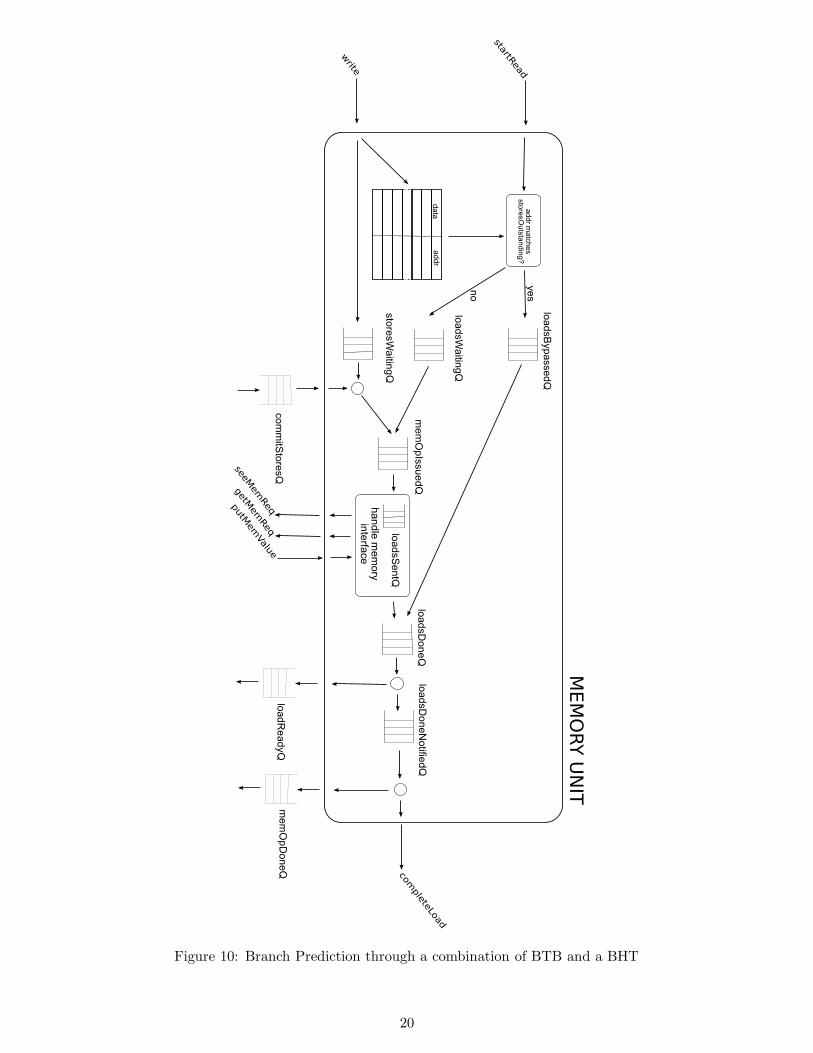
Table 1: Number of cycles to complete qsort and vvadd benchmarks. These include the VERIFY stagefor both benchmarks. qsort retires 24249 instructions. vvadd retires 18026 instructions. This tableshows improvement of our design with new architectural features.
Once those improvements would be done, we re-evaluate our design and select the next course of action,which might be architectural or structural improvement.
The results are presented in three parts. The first part depicts architectural improvements of ourdesign, as we added more speculation and better scheduling ability. The second part shows how theperformance scales as we change two important parameters of the design: ROB size and number ofavailable memory instruction slots in the memory unit. The final part discusses synthesis and place androute results.
6.1 Architectural Exploration
Here we present performance numbers for a number of snapshots of our design. Those include:
• our basic in-order design
• basic design with a branch history table predictor
• basic design with out-of-order scheduling
• basic design with OoO and BHT
• OoO and BHT with improved branch predict/mispredict penalty
• OoO, BHT, fast (mis)predict with speculative OoO memory unit
• OoO, BHT, fast (mis)predict with speculative OoO memory unit and BTB in PCGen; this is ourfinal design
We present number only for qsort and vvadd benchmarks, as those were the ones we were collectingwhile doing the project. We do not have time to re-compile and re-run the two new benchmarks (medianand towers) on all of our design explorations.
Table 1 provides number of cycles the two bencharks took to complete on our various designs. Forqsort, each set of improvements added a small amount of performance. The final result is a design thathas an IPC 43% higher than the basic design on qsort. This is because qsort has a rather irregularexecution pattern with lots of memory accesses blocking the execution. vvadd has a very differentbehavior. It received two very large performance improvements from an improved branch mispredictionstrategy and a small BTB in the PCGen. This is because vvadd has a very regular structure with onlya single branch in the main loop. Reducing the penalty for taking that branch gives a very notableimprovement. The final IPC of vvadd is 3.7x higher than the original design.
6.2 Final Design parameter exploration
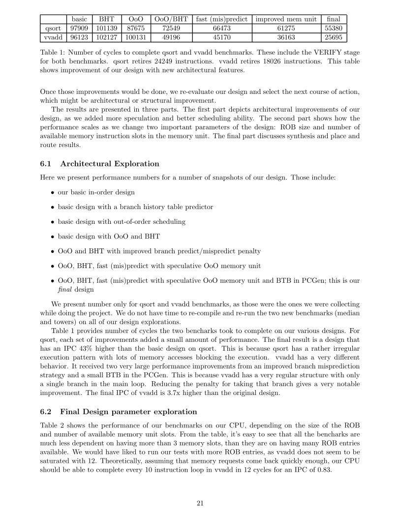
Table 2 shows the performance of our benchmarks on our CPU, depending on the size of the ROBand number of available memory unit slots. From the table, it’s easy to see that all the bencharks aremuch less dependent on having more than 3 memory slots, than they are on having many ROB entriesavailable. We would have liked to run our tests with more ROB entries, as vvadd does not seem to besaturated with 12. Theoretically, assuming that memory requests come back quickly enough, our CPUshould be able to complete every 10 instruction loop in vvadd in 12 cycles for an IPC of 0.83.
21
rob size / mem opslots available vvadd qsort median towers
12/6 0.736 0.425 0.328 0.320
10/6 0.663 0.413 0.328 0.322
8/6 0.586 0.370 0.316 0.315
6/6 0.434 0.340 0.294 0.297
4/6 0.294 0.249 0.229 0.229
2/6 0.100 0.099 0.096 0.093
12/6 0.736 0.425 0.328 0.320
12/5 0.736 0.425 0.328 0.313
12/4 0.736 0.424 0.328 0.310
12/3 0.736 0.420 0.328 0.298
12/2 0.553 0.415 0.303 0.268
12/1 0.399 0.362 0.272 0.184
Table 2: IPC of our CPU with different sized ROB and MemUnit slots
6.3 Final Design Synthesis and Place and Route
Our final synthesized and laid-out design is somewhat slower than the design we presented. We haveadded a good amount of logic in our MemUnit, as it now disambiguates addresses of loads and stores,which requires doing a comparison between the incoming load and every remembered store. The designwe’re presenting here has 6 memory unit slots available, thus requires a single cycle read of 6 32-bitvalues, a comparison between those and the incoming instruction’s address and a decision on whereto send the request (loadsWaitingQ or loadsBypassedQ). We’d like to re-synthesize the design with 3memory slots available to potentially improve our performance, and definitely reduce our area.
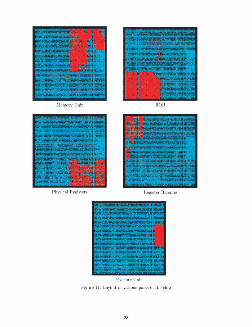
The final placed-and-route’d design reports a clock cycle of 10.34ns and an area of 543145.9µm2 .
Figure 11 shows some of our biggest synthesized modules.