PIPE, FITTINGS AND MANUAL VALVES PP-H The PP-H line consists of a comprehensive range of pipes, fittings and valves for use in the construction of process and service lines for conveying pressurised industrial fluids at maximum working temperatures of no more than 100 °C.
Polypropylene is a thermoplastic and partially crystalline resin belonging to the family of polyolefins.PP is obtained through the polymerization of propylene (C3H6) with the aid of catalysts. For use in piping systems, the latest-generation Polypropylene Homopolymer variant, or PP-H, offers excellent performance at working temperatures of up to 100° C and a high resistance to chemicals due to the excellent physical and thermal characteristics of the resin.
The PP-H line in latest-generation Polypropylene Homopolymer consists of a comprehensive range of pipes, fittings and valves for use in the construc-tion of process and service lines for conveying pressurised industrial fluids and for maximum operating temperatures of up to 100° C.The entire line is made of Polypropylene Homopolymer resins MRS 100 (PP-H 100) according to the classification DIN 8077-8078, DIN 16962 and approved by DIBt - Deutsches Institut für Bautechnik for use in industrial processes.The main properties of the latest-generation Homopolymer resins are:• High chemical resistance: In addition to ensuring excellent chemical resistance, especially against
halogens and alkaline solutions, the use of PP-H resins with special addi-tives also ensures excellent mechanical properties when conveying deter-gents and similar chemicals.
PP-H resins are also fully compatible with the transport of drinking, un-conditioned, demineralised and spa water for therapeutic and kinothera-peutic uses.
• Excellent thermal stability: Particularly in the intermediate temperature range between 10° C and 80°
C typical of industrial applications, PP-H ensures excellent mechanical strength and impact resistance with high safety factors.
• Resistance to ageing: PP-H resins have a high circumferential breaking strength (Minimum
Required Strength MRS ≥ 10.0 MPa at 20°C) and allow long installation lifetimes without showing any signs of significant physical-mechanical deterioration.
GENERAL CHARACTERISTICS
2
DensityTest method ISO 1183Unit of measurement g/cm3
Value Valves/fittings/pipes: 0.9
Fluidity index (MFI 190° C, 5 kg)Test method ISO 1133Unit of measurement g/(10 min)Value Valves/fittings/pipes: 0.5
Modulus of elasticityTest method ASTM D 790Unit of measurement MPa = N/mm2
Value Valves/fittings/pipes: 1300
IZOD notched impact strength at 23°CTest method ASTM D256Unit of measurement J/mValue Valves/fittings/pipes: 150
Ultimate elongationTest method ISO 527Unit of measurement %Value Valves/fittings/pipes: >50
Rockwell hardnessTest method ASTM D785Unit of measurement RValue Valves/fittings/pipes: 100
Tensile strengthTest method ISO 527Unit of measurement MPa = N/mm2
Value Valves/fittings/pipes: 30
Heat distortion temperature HDT (0.46 N/mm2)Test method ASTM D648Unit of measurement °CValue Valves/fittings/pipes: 96
Thermal conductivity at 20° CTest method DIN 5216Unit of measurement W/(m °C)Value Valves/fittings/pipes: 0.22
Coefficient of linear thermal expansionTest method DIN 53752Unit of measurement m/(m °C)Value Valves/fittings/pipes: 16 x 10-5
• ANSI B16.5 cl.150 Pipe, flanges and stubs - NPS 1/2 to NPS 24 mm / inch.• ASTM D 4101-06 Polypropylene compound according to the classification PP0110B56000.• BS 10 Specification for flanges and bolts for pipes, valves and fittings.• BS 1560 Flanges for pipes, valves and fittings (Class designated). Steel, cast iron
and copper alloy flanges. Specification for steel flanges. • BS 4504 Flanges for pipes, valves and fittings (PN designated).• DIN 2501 Flanges, dimensions.• DIN 2999 Whitworth thread for threaded pipes and fittings.• DIN 8077-8078 PP-H pipe dimensions, metric series.• DIN 16962 PP-H fittings for socket and butt welding, dimensions.• DIN 16963 Pipe joints and pipe components for pressurised fluids in HDPE.• DVS 2202-1 Imperfections of PP-H welded joints, characteristics, descriptions and
evaluations.• DVS 2207-11 Socket and butt welding of PP-H components.• DVS 2208-1 Machinery and equipment for thermocouple welding pipes, pipe parts and
panels.• EN 558-1 Industrial valves - Overall dimensions of metal valves for use in flanged
pipe systems - Part 1: PN designated valves• EN 1092-1 Flanges and their joints - Circular flanges for pipes, fittings, valves and ac-
cessories - Part 1: Steel flanges, PN designated.• EN ISO 15494 Specifications for components (Pipes, Fittings and Valves) in PP-H for
industrial applications.• ISO 228-1 Pipe threads for connections that do not seal in the thread.• ISO 5211 Part-turn actuator couplings.• ISO 7005-1 Metal flanges; part 1: steel flanges.
STANDARDSProduction of the PP-H (100) lines is carried out according to the highest quality standards and in full compliance with the environmental restrictions set by the applicable laws in force and in accordance with ISO 14001. All products are made in accordance with the quality guarantee system in compliance with ISO 9001.
4
• JIS B 2220 Steel pipe flanges.• UNI 11318 Socket welding of PP-H components.• UNI 11397 Butt welding of PP-H components.
5
APPROVALS AND
• DIBt FIP PP-H valves have been tested and certified by DIBt (Deutsches Institut
für Bautechnik)
• GOST-R - EAC FIP PP-H valves are GOST-R and EAC certified in accordance with Russian
regulations on Safety, Hygiene and Quality
• RINA FIP PP-H valves have been recongnised as suitable for conveying, treating
domestic and air conditioning waters on board ships and other units clas-sified by RINA.
• TA-Luft FIP PP-H valves have been tested and certified according to “TA-Luft” by
MPA Stuttgart in compliance with the Technical Instruction on Air Quality Control TA-Luft/ VDI 2440
• UKR SEPRO FIP PP-H valves and fittings are certified in accordance with Ukrainian regu-
lations on Safety and Quality
QUALITY MARKS
TA-Luft
6
MAINPROPERTIES
Properties of PP-H BenefitsThermal resistance - service range 0 °C -100 °C (see
Easy jointing (hot socket, butt and electrofusion welding, flanging and threading)
- low installation costs- possible connection with many
accessories and appliances
Low specific weight - low transport costs- ease of handling and installation
7
SOCKET WELDINGINSTRUCTIONS
Fig. 1
Hot socket welding involves fusing the pipe in the fitting's socket. The joint is made by simultaneously fusing the male and female surfaces by means of special manual or automatic heating devices. These devices, in their simplest form, are composed of a heating plate on which a series of heating bushes are assembled. The devices comes with an appropriate heating system complete with an automatic tempera-ture controller. No additional materials are required for this type of welding. Socket welding does not affect the chemical resistance of the polypropylene, nor does it influence the inner pressure resistance of the assembled pipes and fittings. The pipe to be welded must be cut, chamfered and peeled if necessary. The external surface of the pipe and the internal surface of the fitting must be carefully cleaned, and the external surfaces of the pipe and fitting can be marked with a reference notch to eliminate the risk of inadvertent rotation while the joint is setting. The next step is to insert the pipe in the female bush and the fitting in the male bush and hold them in position for the necessary heating time; when this time has elapsed, the parts must be quickly removed from the bushes and then the pipe inserted into the fitting to the full previously determined insertion length, ensuring the reference notches are correctly aligned. The two elements must be supported for approximately 15 sec-onds after initial insertion and then left to cool at ambient temperature without using forced air flows or water immersion.Procedure for hot socket weldingThe method described below is applicable only when creating thermal socket welds that call for the use of manual type welding equipment (fig. 1). The use of automatic and semi-automatic appliances, which are particularly suitable for diameters greater than 63 mm, calls for a specific working knowledge of the welding tool. In this case, adhere strictly to the tool manufacturer's instructions.1) Select the female bushes and the male bushes of the required diameters, insert
them and secure them to the heating plate (fig. 2).2) Carefully clean the contact surfaces (fig. 3). When choosing the type of liquid de-
tergent, use recommended products supplied by specialist producers: trichloro-ethane, chlorothene, ethyl alcohol and isopropyl alcohol are all suitable.
3) Set the temperature of the heating tool. To form the joint correctly, the tempera-ture should be set between 250° C and 270° C.
4) When the appliance has reached the preset temperature, check the temperature of the heating plate using a fast acting thermoprobe.
5) Cut the pipe at right angles, chamfer it and if necessary peel it out (fig. 4-5). The peeling diameter and length and the chamfer depth must correspond to the val-ues shown in the table named “Pipe peeling and chamfer dimensions”. The cham-
Fig. 2
Fig. 3 Fig. 4 Fig. 5
8
Fig. 6
Fig. 7
Fig. 8
Fig. 9 Fig. 10 Fig. 11
fering process can be performed either after peeling or concurrently with this operation, using special calibrated tools.
6) Mark the pipe with the insertion length L1 (fig. 6), referring to the values indicat-ed in the table named “Pipe insertion length” and checking that any peeling has been machined to the entire length shown in the table.
7) Mark a longitudinal reference line on the outside of the pipe and the fitting to prevent the two parts from rotating while the joint is being made (fig. 7).
8) Clean the fitting and pipe from any traces of oil or dust on the weld surfaces (fig. 8).9) After having checked that the surface temperature of the heating plate has sta-
bilized at the required value, insert the pipe into the female bush and the fitting in the male bush (fig. 9). Holding the parts inserted in the two bushes (fitting inserted to limit stop, pipe inserted up to the end of the peeling length), wait for the minimum heating time shown in the table named “Heating, welding and cool-ing times”.
10) When the minimum heating time has elapsed, quickly remove the elements from the bushes and fit the pipe into the fitting for the entire insertion length L1 marked previously (fig. 10). Do not turn the pipe in the fitting; ensure the longitu-dinal reference marks are perfectly aligned (fig. 11).
11) Hold the jointed elements for the welding time shown in the table named “Heating, welding and cooling times” and then leave them to cool slowly at ambi-ent temperature without using forced air flows or water immersion.
12) When the internal and external surfaces have cooled sufficiently, pressurize the plant for the joint hydraulic test.
9
External diameter
de (mm)
Peeling length
L (mm)
Chamfer
Sm (mm)
20 14 225 16 2
32 18 2
40 20 2
50 23 2
63 27 3
75 31 3
90 35 3
110 41 3
External diameter
de (mm)
Length of insertion into the fitting's socket
L1 (mm)
20 1425 15
32 17
40 18
50 20
63 26
75 29
90 32
110 35
PIPE PEELING AND CHAMFER DIMENSIONS
PIPE INSERTION LENGTH
HEATING, WELDING AND COOLING TIMES
de (mm)
Polypropylene pipes according to: DVS 2207 Part 11
* For proper welding, we recommend using pipes with wall thickness exceeding 2 mm, and precisely:
- for d up to 50 mm: pipe series PN 10 and PN 16 - for d from 63 to 110 mm: pipe series PN 16, PN 10 and PN 6.
10
BUTT WELDINGINSTRUCTIONSButt welding with contact heating elements is the process of jointing two elements (pipes and/or fittings) of the same diameter and thickness, the joining surfaces of which are heated until fusion by contact with a heating element and then, after the heating element has been removed, are pressed together to form the weld.The following instructions are provided for reference purposes only. Installers must be properly trained and have an in-depth knowledge of the procedures to be fol-lowed according to the type of welding equipment being used.
PRELIMINARY CHECKS BEFORE WELDINGTo ensure the joint is made properly:
• Ambient temperatures must be within the range from +5 °C to +40 °C.
• When inspecting the elements to be welded together, check the dimensions (check for excess ovality)
• Check the working temperature of the heating element with a calibrated contact thermometer. This measurement must be made 10 minutes after the rated tempera-ture has been reached, thus allowing the element to heat up over its entire surface area and depth. Fusion temperature must be between 200° C and 220° C.
• Check the surface of the heating element (integrity of the non-stick coating) and clean with a lint-free cloth or soft paper wipe.
• Check that the welding unit is functioning correctly.
• Check the efficiency of the welding unit jaw clamps; ensure they are able to guar-antee the correct alignment between the two sides of the joint and that the con-tact surfaces are perfectly parallel.
• Check the pulling force of the carriage, both in terms of friction and in relation to the load to be moved (pipes or fittings).
• Check the efficiency of the measuring instruments (pressure gauge and timer).
• Check that the pipes and/or fittings to be welded together are of the same diam-eter and thickness (same SDR).
PREPARING FOR WELDING• Cleaning the surfaces: Before positioning the parts to be welded, remove all traces of dirt, grease, oil,
dust, etc., from the external and internal surfaces of the ends, using a clean, lint-free cloth soaked in a suitable detergent. When choosing the type of liquid deter-gent, use recommended products supplied by specialist producers: trichloroethane, chlorothene, ethyl alcohol and isopropyl alcohol are all suitable.
• Clamping the ends: The ends of the two parts to be welded must be clamped in such a way that axial
misalignment does not exceed 10% of the thickness (fig. 1).
• Planing the edges to be welded: To guarantee proper parallelism and flatness, and, equally important, to eliminate
the film of oxide that forms, the ends of the two parts to be joined must be planed. When this procedure is concluded, bring the two ends into contact and ensure that any clearances between them do not exceed 0.5 mm. The shavings must form continuously on both the edges to be welded (fig. 2). It is good practice, after the planing stage, to inspect the resulting shavings to verify the absence of manufac-turing defects. Shavings must be removed from the internal surface of the com-ponents to be welded using a brush or a clean cloth. In any event, after planing, the two surfaces must not be touched or contaminated in any other way; for this reason the welding operations must be performed immediately after preparation. If
Fig. 1
Fig. 2
11
any traces of dust have settled on the planed surfaces, before they can be welded they should be cleaned with a cloth soaked in specific detergent.
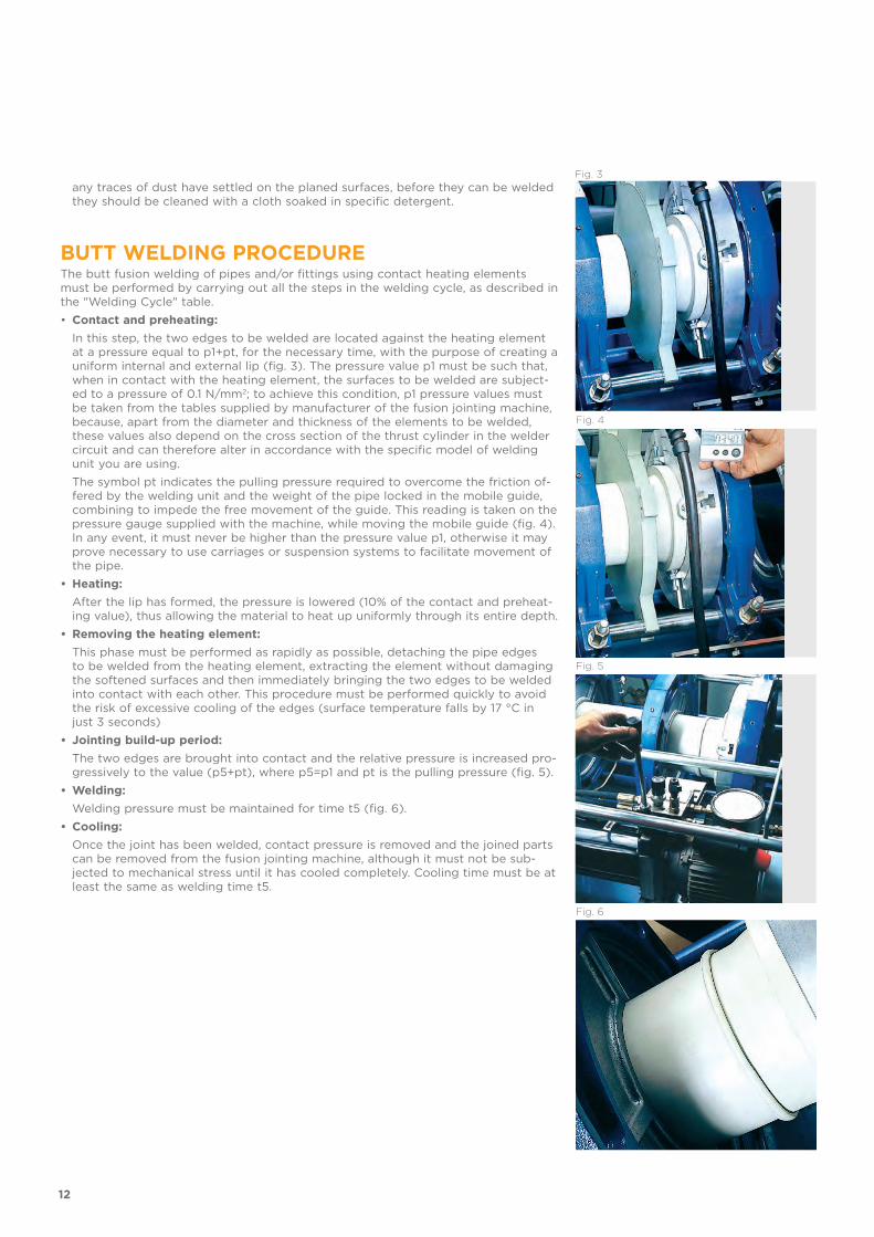
BUTT WELDING PROCEDURE The butt fusion welding of pipes and/or fittings using contact heating elements must be performed by carrying out all the steps in the welding cycle, as described in the "Welding Cycle" table.• Contact and preheating: In this step, the two edges to be welded are located against the heating element
at a pressure equal to p1+pt, for the necessary time, with the purpose of creating a uniform internal and external lip (fig. 3). The pressure value p1 must be such that, when in contact with the heating element, the surfaces to be welded are subject-ed to a pressure of 0.1 N/mm2; to achieve this condition, p1 pressure values must be taken from the tables supplied by manufacturer of the fusion jointing machine, because, apart from the diameter and thickness of the elements to be welded, these values also depend on the cross section of the thrust cylinder in the welder circuit and can therefore alter in accordance with the specific model of welding unit you are using.
The symbol pt indicates the pulling pressure required to overcome the friction of-fered by the welding unit and the weight of the pipe locked in the mobile guide, combining to impede the free movement of the guide. This reading is taken on the pressure gauge supplied with the machine, while moving the mobile guide (fig. 4). In any event, it must never be higher than the pressure value p1, otherwise it may prove necessary to use carriages or suspension systems to facilitate movement of the pipe.
• Heating: After the lip has formed, the pressure is lowered (10% of the contact and preheat-
ing value), thus allowing the material to heat up uniformly through its entire depth.• Removing the heating element: This phase must be performed as rapidly as possible, detaching the pipe edges
to be welded from the heating element, extracting the element without damaging the softened surfaces and then immediately bringing the two edges to be welded into contact with each other. This procedure must be performed quickly to avoid the risk of excessive cooling of the edges (surface temperature falls by 17 °C in just 3 seconds)
• Jointing build-up period: The two edges are brought into contact and the relative pressure is increased pro-
gressively to the value (p5+pt), where p5=p1 and pt is the pulling pressure (fig. 5).• Welding: Welding pressure must be maintained for time t5 (fig. 6).• Cooling: Once the joint has been welded, contact pressure is removed and the joined parts
can be removed from the fusion jointing machine, although it must not be sub-jected to mechanical stress until it has cooled completely. Cooling time must be at least the same as welding time t5.
Irregular path of the weld bead around the circumference of the pipePossible causes Insufficiently meticulous preparation of ends to be welded
with consequent uneven heat distribution
Reduced size of weld beadPossible causes Incorrect adjustment of welding parameters (temperature,
pressure and time)
Notch in centre of bead is too deepPossible causes Temperature or pressure values are too low
Inclusions in the surface of the weld beadPossible causes Insufficient cleaning of the ends to be welded
Porosity of weld beadPossible causes Welding performed in excessively humid ambient conditions
Surface of weld bead presents an excessively smooth shiny finishPossible causes Overheating during welding
Misalignment exceeds 10% of the thickness of the pipe and the fittingPossible causes Incorrectly executed centring or excessive ovality of pipe
The table reports the most common types of defect encountered if the correct welding procedure is not followed.
Joints can be checked using two alternative techniques: non-destructive tests and de-structive tests. While these latter tests call for the use of special equipment, the quality of the joint can also be checked with a simple visual inspection.Visual inspections should assess the following points:a) The weld bead must be uniform around the entire circumference of the joint;b) The notch in the centre of the bead must remain above the outside diameter of the
welded parts;c) The external surface of the bead must not show any signs of porosity or inclusions of
dust or other contaminants;d) There should be no visible signs of surface breakup;e) The surface of the weld bead should not have a very highly reflective finish, as this is
a sign of overheating;f) Axial misalignment of the welded parts must be no greater than 10% of their thickness.
CHECKING THE QUALITY OF THE WELDED JOINT
14
dSDR = __ s
(SDR - 1)ISO-S = ________ 2
σPN = ______ ISO-S
MRSσ = ____
c
d Wall thickness S (mm)SDR 11 - ISO S 5 SDR 17.6 - ISO S 8.3
PP-H components can be welded to compatible components in PPR and PPB without problems, once that the compatibility of the MFI value according to the DVS standard is verified. Because of the difference between PP-H and PPR in terms of MRS (MRS10 for PP-H, MRS8 for PPR, where MRS or Minimum Required Strength is the minimum guaranteed breaking strength of the material, subjected to tangential tension using hydrostatic pressure, at a temperature of 20 °C and for a lifetime of 50 years) and the consequent safety factors to be adopted (Table 1), exact correspondence of the wall thickness / outside diameter ratio is of the maximum importance. For this purpose, both the SDR (Standard Dimension Ratio) and the Series of thickness-es S have been introduced. In accordance with standard EN ISO 15494-1, the safety fac-tor to be adopted and the SDR/Series determine the reference nominal pressure value PN (PN: max. working pressure in bar at 20 °C, for a duration of 50 years, in water).
Working temperature Safety factor
10 °C < t < 40 °C 1.640 °C < t < 0 °C 1.4
t > 60 °C 1.25
SAFETY FACTORS
WALL THICKNESS
COMPATIBILITY AND SAFETY FACTORS
15
ISO-UNI PIPEPP-H
Pressure pipe
18
Technical specificationsSize range d 20 ÷ d 400 (mm)Nominal pressure SDR 17, 6 (PN6) with water at 20 °C
SDR 11 (PN10) with water at 20 °CTemperature range 0 °C ÷ 100 °CCoupling standards Welding: EN ISO 15494.
Can be coupled to pipes according to EN ISO 15494Reference standards Construction criteria: EN ISO 15494
Test methods and requirements: EN ISO 15494Installation criteria: DVS 2202-1, DVS 2207-11,DVS 2208-1, UNI 11318, UNI 11397
Material PP-H
PIPE
Pressure pipes for connection system by butt or socket welding.
PRESSURE PIPE
ISO-UNI
19
TECHNICAL DATAREGRESSION CURVES FOR PIPES IN PP-HRegression coefficients in accordance with standards DIN and EN ISO for MRS = 10 N/mm2
The information in this leaflet is provided in good faith. No liability will be accepted concerning technical data that is not directly covered by recognised international standards. FiP reserves the right to carry out any modification. Products must be installed and maintained by qualified personnel.
For water and non-hazardous fluids with regard to which the material is classified as CHEMICALLY RESISTANT. In other cases, a reduction of the nominal pressure PN is required.A = SDR 11 ISO-S5 - 5 yearsB = SDR 11 ISO-S5 - 25 yearsC = SDR 17.6 ISO-S8.3 - 5 yearsD = SDR 17.6 ISO-S8.3 - 25 years
PRESSURE VARIATION ACCORDING TO TEMPERATURE
-40 -20 0 20 40 60 80 100 120 140 °C
16
14
12
10
8
6
4
2
0
Wor
king
pre
ssur
e
Working temperature
bar
AB
CD
Ho
op
str
ess
Time to failure
bar0.1 1 10 102 103 104 105 106 h
20
25
304050
15
10
0.5
1
1.5
2
2.533.545
6789
1 5 10 25 50 100Years
20 °C10 °C
30 °C40 °C50 °C
70 °C80 °C
90 °C95 °C
110 °C
60 °C
20
PRESSURE VARIATION ACCORDING TO TEMPERATUREFor water and non-hazardous fluids with regard to which the material is classified as CHEMICALLY RESISTANT. In other cases, a reduction of the nominal pressure PN is required.E = SDR 11 ISO-S5 - 10 yearsF = SDR 11 ISO-S5 - 50 yearsG = SDR 17.6 ISO-S8.3 - 10 yearsH = SDR 17.6 ISO-S8.3 - 50 years
-40 -20 0 20 40 60 80 100 120 140 °C
16
14
12
10
8
6
4
2
0
Wor
king
pre
ssur
e
Working temperature
bar
E
F
GH
21
Pressure pipePP-H pressure pipe according to DIN 8077/8078, Beige - RAL 7032, standard length 5m
Supporting PP-H pipes conveying liquids of density 1 g/cm3 (water and other fluids of equal intensity)
Supporting PP-H pipes conveying liquids of density other than 1 g/cm3. If the liquid being conveyed has a density other than 1 g/cm3, the distance L must be multiplied by the factors in the table
INSTALLATIONThe installation of thermoplastic pipe systems requires the use of support clips to pre-vent flexing and the resulting mechanical stresses.The distance between the clips depends on the pipe material, SDR, surface temperature and the density of the conveyed fluid.Before installing the clips, check the distances reported in the table below, as provided for by guidelines DVS 2210-01 for water pipes.
Fluid density in g/cm3 Support factor
1.25 0.96
1.50 0.92
1.75 0.88
2.00 0.94
< 0.01 1.30 for SDR111.47 for SDR17.6
POSITIONING OF ZIKM AND ZAKM PIPE CLIPS
* The distance L can be increased by 30% in case of vertical installation of the pipe
For different SDR values, multiply the data in the table by the following factors:0.91 for SDR 17 and SDR 17.6
For pipes of SDR 11 / S 5 / PN 10:
d mmdistance L in mm at different wall temperatures*
< 20° C 30° C 40° C 50° C 60° C 70° C 80° C16 650 625 600 575 550 525 500