Pipe supports bear the dead loading, live loading, wind, snow, and seismicloadings, as well as the loads imposed or caused by variations in temperatures,both ambient and the contained fluid. Pipe supports must prevent exceeding thestress limit of the piping material, and prevent excessive forces and moments onthe equipment to which the piping is attached. Also to be considered are the fluiddynamic forces, such as water hammer and steam hammer.
The American Society of Mechanical Engineers (ASME) publishes The Code forPressure Piping B31. The Power Piping Code (B31.1) is one of several sectionsof this code that applies to “power and auxiliary service piping systems for
electric generating stations; industrial and institutional plants; central and districtheating plants; and district heating systems, both on the property of and withinthe buildings of the users”. This course will refer to B31.1 as the governing codefor the subject covered herein. Pressure piping systems in other facilities, suchas chemical plants and refineries, each have their own governing codes, andshould be referred to, as appropriate. The requirements for pipe supports andhangers are, however, very similar to those of B31.1.
Nothing in this course is intended to modify or supplant anything in B31.1 or anyother governing codes.
The term “pipe supports” is used in a generic sense that includes pipe hangersand restraints, and any other structure or device that bears the weight or restrictsthe movements of piping.
Pipe support illustrations are taken from ITT Grinnell catalog PH 81.
Steps in Designing Pipe Supports
There are three loosely defined steps in pipe support design:
1. Developing a preliminary piping layout2. Performing a piping stress analysis3. Selecting the individual pipe supports configurations and components
The preliminary piping layout is of necessity done by the piping designagency, and is described in the next section.
The pipe stress calculations can be done by the design agency or by the pipesupport contractor. It often is more convenient to assign both the stress analysisand the detailed pipe support configurations and supply to the generalconstruction contractor, who will then subcontract it to a pipe supportsubcontractor. This is because the stress analysis and the pipe support
configurations are closely related, and often reiterative processes, and thereforefit nicely into a single scope of responsibility package. The argument against thisis that the pipe stress calculations and decisions should remain with the designengineer of record, and not delegated to the general contractor or to a pipesupport supplier. The latter approach is strongly recommended. If, however, thepipe stress is delegated, the stress should still be performed under thesupervision of a Professional Engineer, and the stress analysis so stamped.
The detailed configuration of the supports is usually left to the pipe supportsupplier or contractor because the details can vary with suppliers, and thesuppliers can most efficiently and effectively perform this function. The final
configuration drawings should then be reviewed an approved by the designengineer of record.
Preliminary Layout
The physical layout of piping systems must take into account how the systemsare to be supported. Two primary considerations at this stage are inherentflexibility of the piping system, and structural attachments for the supports.Inherent flexibility is necessary to deal with the effects of thermal expansion andcontraction. It is accomplished by including bends or loops in the piping, and isthe work for an experienced piping designer. Also, of course, the piping must be
routed where there is concrete or steel from which to support it.
In preliminary piping layouts, the experienced designer will take intoconsideration such things as the pipe size and wall thickness, and the maximumrange of temperatures the piping will be subjected to. He or she will then, eitherby rule of thumb or guesswork, lay out the piping using bends, loops, andoffsets. Expansion joints or ball joints may also be included for additionalflexibility in tight areas. Anchor points and tentative pipe support locations areselected. Allowable forces and moments at equipment nozzles are assumed,pending input from the equipment vendors. At this point, the responsibleengineer must decide the degree of pipe stress analysis that will be performed.
The Power Piping Code
The Power Piping code (ANSI / ASME B31.1) requires that “power pipingsystems subject to thermal expansion or contraction or to similar movementsimposed by other sources shall be designed in accordance with the requirementsfor the evaluation or analysis of flexibility and stresses specified herein”, and forall piping to take thermal stress “into consideration”.
The Power Piping Code states the degree of stress analysis that must beperformed to conform with the code. I will quote:
“All piping shall meet the following requirements with respect to thermal
expansion and flexibility: (A) It shall be the designer’s responsibility to perform an analysis unless the system meets one of the following criteria. (A.1) The piping system duplicates a successfully operating installation or replaces a system with a satisfactory service record. (A.2) The piping system can be adjudged adequate by comparison with previously analyzed systems. (A.3) The piping system is of uniform size, has not more than two anchors and no intermediate restraints, is designed for essentially non-cyclic service (less than 7000 total cycles), and satisfies the following approximate criterion:
(a) English units
DY / (L-U)² is less than or equal to 0.03 (b) SI units (6944.44) x [DY / (L-U)²] is less than or equal to 208.3
Where: D = nominal pipe size in inches or mm Y = resultant of movements to be absorbed by the pipelines in inches or mm. L = developed length of line axis in ft. or m. U = anchor distance (length of straight line joining anchors in ft. or m.)
(B) All systems not meeting the above criteria, or where reasonable doubt exists as to adequate flexibility of the system, shall be analyzed by simplified,approximate, or comprehensive methods of analysis that are appropriate for the specific case. (C) Approximate or simplified methods may be applied only if they are used for the range of configurations for which their adequate accuracy has been demonstrated. (D) Acceptable comprehensive methods of analysis include: analytical, model tests and chart methods which provide an evaluation of the forces, moments, and stresses caused by bending and torsion form the simultaneous consideration of intermediate restraints to thermal expansion of the entire piping system under consideration, and including all external movements transmitted to the piping by its terminal and intermediate attachments. Correction factors must be applied for the stress intensification of curved pipe and branch connections, as provided by the details of these rules, and may be applied for the increased flexibility of such component parts”.
A comprehensive pipe stress analysis of piping systems generally meansapplying a reiterative computer program and finding the optimum combination ofstiffness, flexibility, and growth If the system cannot be made to “stress out”, areconfiguration is sometimes necessary.
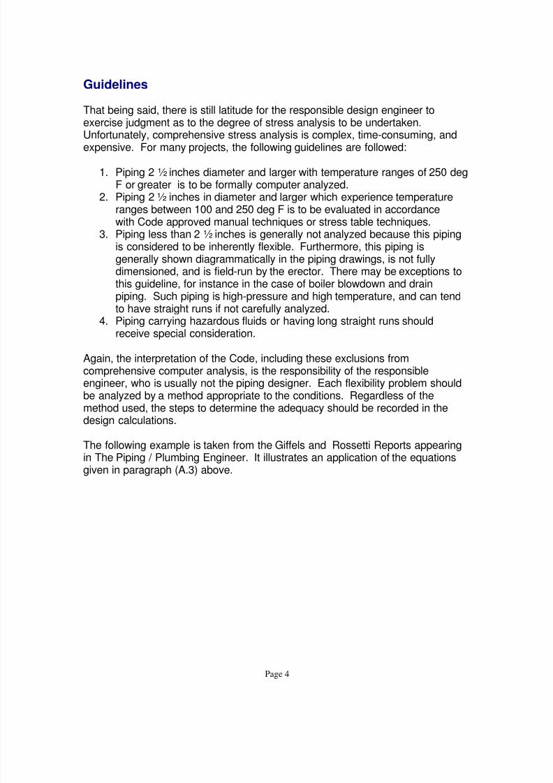
That being said, there is still latitude for the responsible design engineer toexercise judgment as to the degree of stress analysis to be undertaken.
Unfortunately, comprehensive stress analysis is complex, time-consuming, andexpensive. For many projects, the following guidelines are followed:
1. Piping 2 ½ inches diameter and larger with temperature ranges of 250 degF or greater is to be formally computer analyzed.
2. Piping 2 ½ inches in diameter and larger which experience temperatureranges between 100 and 250 deg F is to be evaluated in accordancewith Code approved manual techniques or stress table techniques.
3. Piping less than 2 ½ inches is generally not analyzed because this pipingis considered to be inherently flexible. Furthermore, this piping isgenerally shown diagrammatically in the piping drawings, is not fully
dimensioned, and is field-run by the erector. There may be exceptions tothis guideline, for instance in the case of boiler blowdown and drainpiping. Such piping is high-pressure and high temperature, and can tendto have straight runs if not carefully analyzed.
4. Piping carrying hazardous fluids or having long straight runs shouldreceive special consideration.
Again, the interpretation of the Code, including these exclusions fromcomprehensive computer analysis, is the responsibility of the responsibleengineer, who is usually not the piping designer. Each flexibility problem shouldbe analyzed by a method appropriate to the conditions. Regardless of the
method used, the steps to determine the adequacy should be recorded in thedesign calculations.
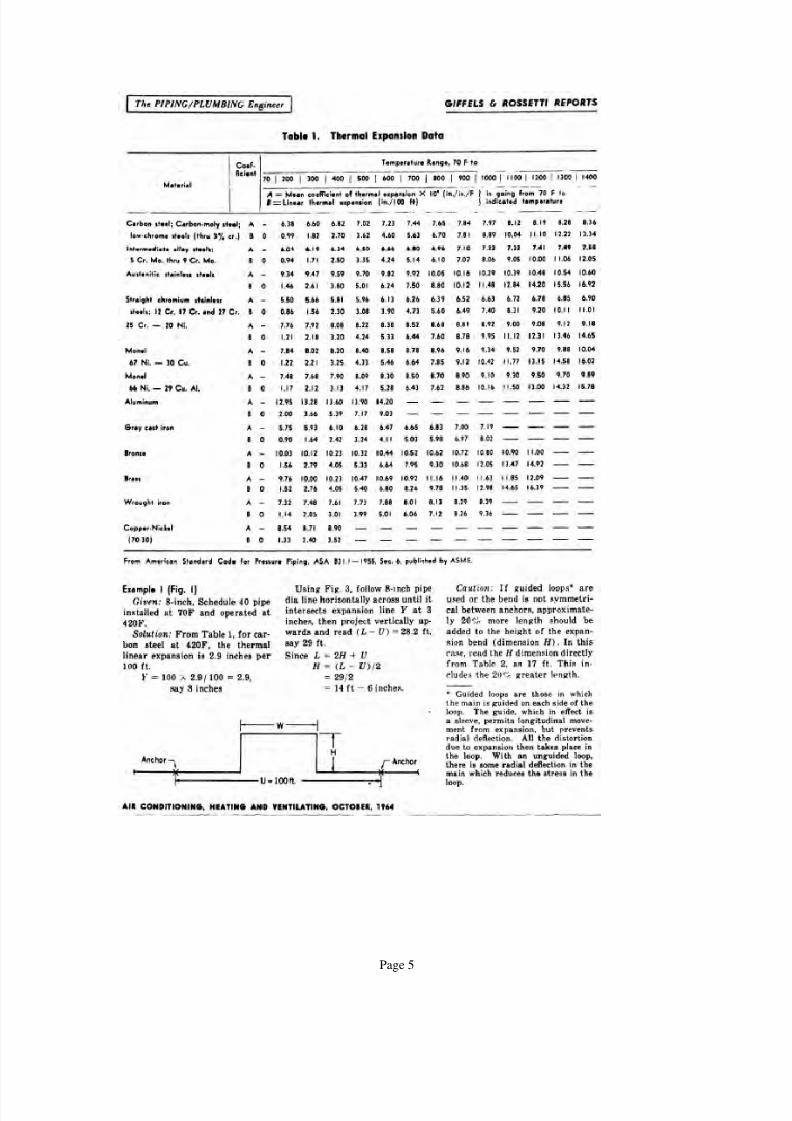
The following example is taken from the Giffels and Rossetti Reports appearingin The Piping / Plumbing Engineer. It illustrates an application of the equationsgiven in paragraph (A.3) above.
Using Fig. 3, follow the six-inch pipe dia. line horizontally until it intersects the
vertical line at (L-U) = 18 feet. The intersecting point indicates that the systemcan safely absorb expansion equivalent to a resultant movement Y = 1.5 inches.Since the actual resultant Y = 1.235 inches, is less, the system has adequateflexibility and no further calculation is necessary.
Cold Springing
Cold springing is a procedure sometimes used to reduce thermal stresses in
piping. The pipe is installed in a pre-stressed condition when cold in such a waythat the stress is relieved when the piping reaches its operating temperature.Larger stress values are allowable at ambient (cold) temperatures than atoperating (hot) temperatures. This procedure must be carefully designed andexecuted, and caution taken if the piping is subsequently cut for future
alterations.
Other Pipe Support Loads
Pipe support loads other than those caused by thermal effects must also beaccounted for, such as:
• Piping dead weight• Live weight, which is the contained fluid. In steam and gas piping
condensation and hydro test liquids must also be accounted for.• Wind, snow, and any other temporary loads.•
Seismic loads.
Reactions at Piping Termination Points
After the resultant of all the piping loads and growth have been calculated orestimated, a second look should be given to the preliminary locations of anchorsand supports previously chosen. A judicious placement of anchors and supportscan help reduce the force and moment reactions at the piping termination pointsat the equipment nozzles. The allowable forces and moments on the equipmentnozzles have to be agreed to with the equipment manufactures. Rotatingequipment such as turbines and pumps are particularly sensitive to nozzle
loadings. Tanks and heat exchanger nozzles often can be reinforced by themanufacturer to withstand heavier loads. The use of expansion joints and ball
joints may also be considered to reduce piping reactions.
Transfer of Forces and Moments to Any point
Flexibility analyses yield forces and moments exerted by piping on its terminalends in three coordinate planes. It is sometimes desired to determine the pipingreactions at some other points remote from the piping connections. It is theneasier to recognize the effects of these forces on other equipment and structure,such as the strength required of a hold-down bolt on a pump or tank.
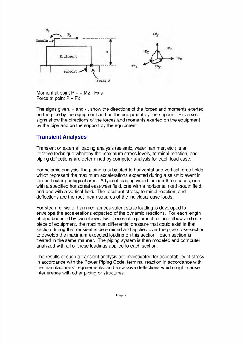
The reactions at any remote point are easily determined in each plane. Theforce and the moment may be transferred anywhere in their plane, but theproduct of the relocated force and the distance the force is moved must be addedalgebraically to the moment.
Moment at point P = + Mz - Fx aForce at point P = Fx
The signs given, + and - , show the directions of the forces and moments exertedon the pipe by the equipment and on the equipment by the support. Reversed
signs show the directions of the forces and moments exerted on the equipmentby the pipe and on the support by the equipment.
Transient Analyses
Transient or external loading analysis (seismic, water hammer, etc.) is aniterative technique whereby the maximum stress levels, terminal reaction, andpiping deflections are determined by computer analysis for each load case.
For seismic analysis, the piping is subjected to horizontal and vertical force fieldswhich represent the maximum accelerations expected during a seismic event in
the particular geological area. A typical loading would include three cases, onewith a specified horizontal east-west field, one with a horizontal north-south field,and one with a vertical field. The resultant stress, terminal reaction, anddeflections are the root mean squares of the individual case loads.
For steam or water hammer, an equivalent static loading is developed toenvelope the accelerations expected of the dynamic reactions. For each lengthof pipe bounded by two elbows, two pieces of equipment, or one elbow and onepiece of equipment, the maximum differential pressure that could exist in thatsection during the transient is determined and applied over the pipe cross-sectionto develop the maximum expected loading on this section. Each section is
treated in the same manner. The piping system is then modeled and computeranalyzed with all of these loadings applied to each section.
The results of such a transient analysis are investigated for acceptability of stressin accordance with the Power Piping Code, terminal reaction in accordance withthe manufacturers’ requirements, and excessive deflections which might causeinterference with other piping or structures.
For systems whose results are unacceptable, there are two solutions. Thepreferred solution is to locate restraints so that the results are acceptable. Thisinvolves a dual iterative technique because not only will a restraint location haveto satisfy the transient analysis, but it is also subjected to another thermalflexibility analysis to assure that the new restraint location does not cause the
thermal stress limits to be exceeded.
The second solution, if the restraint does not work, is to install a hydraulicsnubber or a travel stop. The hydraulic snubber is a device that allows thermalexpansion, but resists the accelerations cause by transients.
Pipe Support Configurations
Pipe hangers and supports are devices which transfer the loads from the pipe orthe structural attachment to the supporting structure or equipment. They includerod hangers, spring hangers, sway braces, turnbuckles, struts, anchors, saddles,
rollers, brackets, and sliding supports. Structural attachments are elements thatare welded, bolted, or clamped to the pipe, such as clips, lugs, clamps, clevises,and stops.
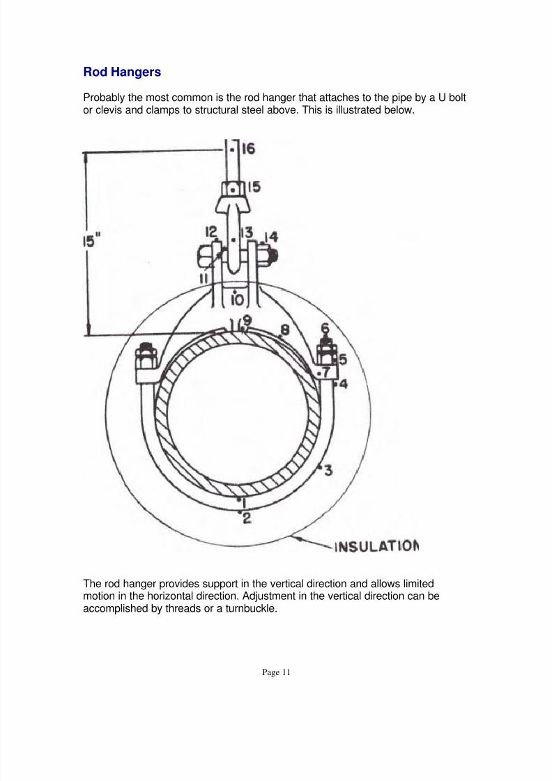
Pipe supports come in many configurations, and are designed to constrain pipemotion in one, two, or three space coordinates. Only the most common types willbe generally described in this course. Manufactures have catalogs thatthoroughly illustrate supports of all types.
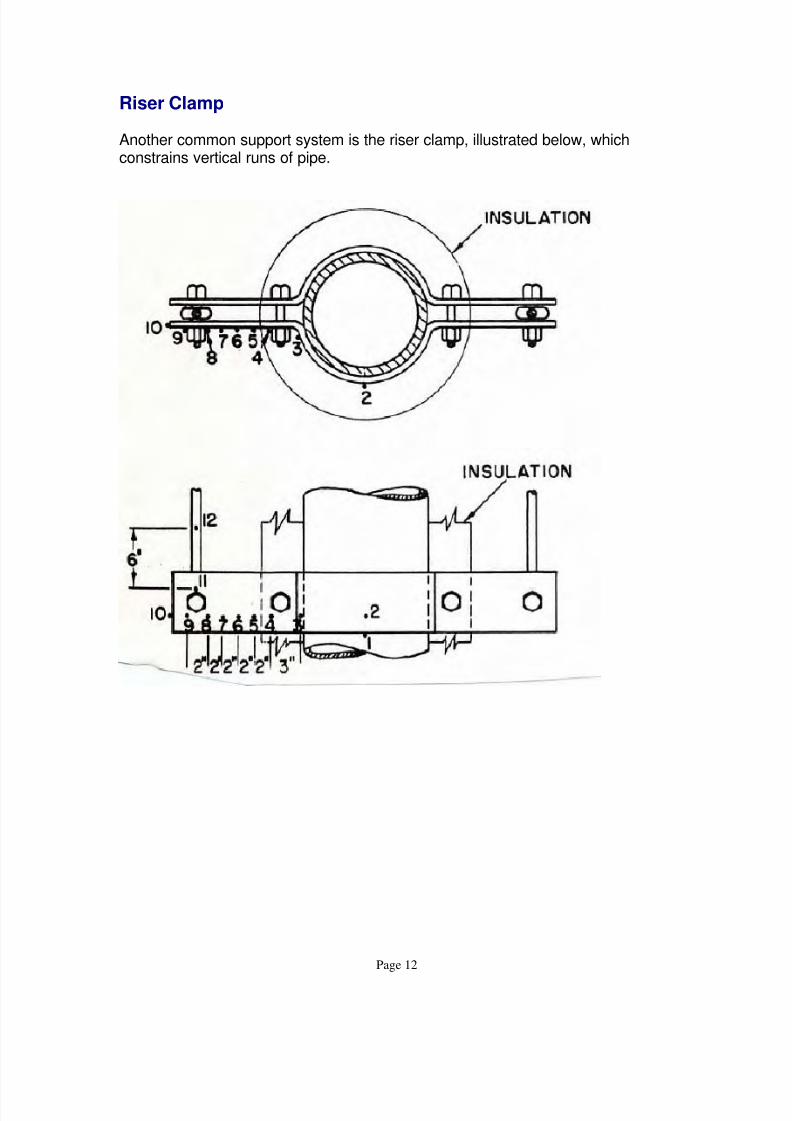
In the following pipe support sketches, the dots (.) indicate suggested locationsfor thermocouples.
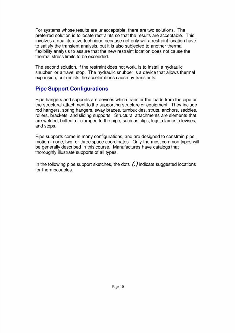
Probably the most common is the rod hanger that attaches to the pipe by a U boltor clevis and clamps to structural steel above. This is illustrated below.
The rod hanger provides support in the vertical direction and allows limitedmotion in the horizontal direction. Adjustment in the vertical direction can beaccomplished by threads or a turnbuckle.
A variable spring hanger is shown next. These devices are installed in locationswhere stresses are not considered to be critical, and where movement permitstheir use. The supporting force varies with the spring deflection. Movement of
the pipe causes the spring to extend or compress. Since the weight of the pipe isthe same in either the hot or cold positions, the variation in the spring forceresults in pipe weight transfer to equipment and adjacent hangers, andconsequently additional stresses on the piping system. Since it is desirable tosupport the actual weight of the pipe in the hot position, when the stressesbecome more critical, the hot load is the dead weight of the pipe. The cold loadis actually under or over supporting the pipe, depending on the movements fromhot to cold.
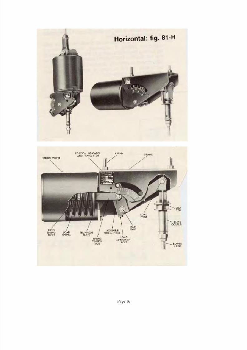
Constant Support Hangers
Constant support hangers provide a constant supporting force for the piping
system throughout its full range of vertical pipe movement. This is accomplishedthrough the use of a spring operating in conjunction with a lever, in such a waythat the spring force times the distance to the lever pivot is always equal to thepipe load times its distance from the pivot point. This type of support is thermallyinvisible, as the supporting force equals the pipe weight throughout the entirethermal cycle. These hangers are used on systems and at locations where thestresses are considered critical.
This is a small sample of the wide variety of hanger and support arrangementsthat can be provided by competent vendors to accommodate any number ofsituations that present themselves in power plants, process, or other facilities thatutilize a variety of piping configurations.
Conclusion
The design of the system and devices that support piping systems in the mannerprescribed by the Power Piping Code ANSI /ASME B31.1, or any other governingcode, including the stress analysis and other analyses that the support designdepends upon, is the responsibility of the Design Engineer of Record, that is, theProfessional Engineer who stamps or seals the piping design drawings. This maynot be the direct quotation of any code of state regulations, but it is a generallyaccepted principle in the trade. This course provides some of the generallyaccepted procedures in designing pipe support systems, but by no means is it
comprehensive.
Pipe support design must be considered an integral part of the design process.