- GRI-00/0193 GRI FINAL DRAFT TOPICAL REPORT NATURAL GAS TRANSMISSION PIPELINES PIPELINE INTEGRITY PREVENTION, DETECTION & MITIGATION PRACTICES Prepared by: THE HARTFORD STEAM BOILER INSPECTION AND INSURANCE COMPANY Gas Research Institute Pipeline Business Unit DECEMBER 2000
Transcript
-
GRI-00/0193 GRIFINAL DRAFT
TOPICAL REPORT
NATURAL GAS TRANSMISSION PIPELINESPIPELINE INTEGRITY
PREVENTION, DETECTION & MITIGATION PRACTICES
Prepared by:
THE HARTFORD STEAM BOILERINSPECTION AND INSURANCE COMPANY
Gas Research InstitutePipeline Business Unit DECEMBER 2000
-
Acknowledgements
The authors acknowledge the leadership and support provided by many individuals in thepreparation of this document. The Interstate Natural Gas Association of America (INGAA) andGas Technology Institute (GTI) worked closely to provide input, direction, review and support.This work was conducted under the direction of John Zurcher of Columbia Energy and KeithLeewis of GTI.
In addition, a number of individuals provided input, review and/or comments that helped tosignificantly improve the final document and make it more inclusive.
We also wish to acknowledge the prior significant effort the American Petroleum Institute (API)member companies and Marty Matheson had in developing an integrity management standardfor liquid pipelines. Many concepts within the standard as well as specific tables and figuresserved as a basis for comparison as this document was drafted.
Thank you all.
Mark Hereth, Ted Clark, and Bernie Selig
- 1 -
NATURAL GAS TRANSMISSION PIPELINESPIPELINE INTEGRITY
PREVENTION, DETECTION & MITIGATION PRACTICES
Executive Summary
There are approximately 325,000 miles of natural gas transmission pipelines in the United States,that transport natural gas from gathering lines and processing plants across the country to localdistribution companies (LDCs) that distribute the gas to homes and businesses.
Transmission pipeline companies spend a large part of their operating budgets to ensure thatpipelines run safely and reliably. A recent GAO report states, “Fatalities from pipeline accidentsare relatively low when compared with those from accidents involving other forms oftransportation.” The Gas Research Institute published report # GRI-00/077 – “The SafetyPerformance of Natural Gas Transmission and Gathering Systems” which describes the safetyperformance of gas transmission pipelines over the past 14 years. While the industry’s safetyrecord is a good one by any measure, it is never good enough.
OPS is developing a new pipeline safety rule – “Pipeline Integrity Management in HighConsequence Areas”, to ensure a comprehensive and integrated approach to pipeline integrity inHigh Consequence Areas (HCA’s).*
Gas transmission pipelines must adhere to various Federal Government regulations from theDepartment of Transportation (predominately 49 CFR Part 192), Environmental ProtectionAgency, U.S. Army Corps of Engineers and Occupational Safety and Health Administration.
Many transmission pipeline companies have programs to prevent pipeline failures, detectanomalies and perform repairs to maintain and improve pipeline integrity and reliability. Theseprograms significantly exceed all the regulatory minimums.
This report shows how the existing pipeline regulations address each of the causes of pipelinefailures. It also shows how industry general practices and voluntary research have addressed andexceed the regulatory minimums. Unlike most regulations, 49 CFR 192 addresses age-relateddeterioration through periodic leak testing, patrols and when the population density increases,mandatory replacement of serviceable pipe with new, heavier wall pipe to mitigate theconsequences of mechanical damage and potential corrosion.
The following conclusions can be drawn from this study and information taken from the listedreferences:
• While gas transmission pipelines are the safest method of energy transportation* (perGAO), the industry continually strives to improve its safety and reliability record.
*See Definitions – page 44
- 2 -
• DOT’s regulation 49 CFR 192 for gas transmission pipelines contains provisions thataddress each of the causes of failures.
• The industry has voluntarily spent more than $100 million over the past 5 years onsafety and reliability research and development, and $33 million just in the areas ofinspection and maintenance. Through appropriate investment now and in the future,developing and new technologies for prevention, detection and repair of pipelines willcontinue to have a significant, positive impact on pipeline safety.
• DOT's regulations for gas transmission pipelines uniquely require the identification ofand additional protection for higher population areas in the proximity of gas pipelinesthrough "class" location design and operations requirements.
• Many pipeline companies significantly exceed regulatory requirements in theiroperations.
• Maintaining pipeline safety and reliability is a complex process. There are presentlymore than 60 different prevention, detection and mitigation practices (not includingmany of the 130 Common Ground reported best practices*) that are applied to the linepipe individually, sequentially or collectively to assure pipeline integrity. Currentregulations require companies to have selected aspects of a comprehensive integritymanagement plan within their Operations and Maintenance Plan.
• Many pipeline companies use some form of risk-based analysis to assess the conditionof their system and to prioritize their prevention, detection and mitigation efforts.
• The pipeline industry is continually updating industry standards that enhance pipelinesystem safety.
• A comparison of total systems versus class 3 and 4 incidents shows that the rates ofincidents are comparable, the majority of class 3 and 4 incidents are due to third-partydamage and their net consequences are no deaths, 16 injuries (10 through third-partydamage) over a 15-year period.
• Based on presented data, it is important to recognize that while pipelines within HighConsequence Areas (HCAs) are an important safety issue, the remaining system'sintegrity must be carefully addressed as well. Regulations should be framed to permitthe industry the ability to provide the most effective safety on a system-wide basis,reducing the frequency of failures as well as the consequences.
*Common Ground Report (see DOT Website)
- 3 -
NATURAL GAS TRANSMISSION PIPELINESPIPELINE INTEGRITY
BY PREVENTION, DETECTION & MITIGATION PRACTICES
Table of Contents
Page
Executive Summary 1
1. Introduction 4
2. Background: Integrity Management of Natural Gas Pipelines 6
3. Pipeline Threats & Impacts 11
4. Comparison of Practices versus Requirements 14
5. Regulatory Requirements to Address Threats 19
6. Industry Prevention and Detection Practices 23
7. Industry Mitigation and Repair Practices 31
8. Integrity Management 33
9. Integrity Management Programs for HCAs 37
10. Industry Safety R&D Initiatives 41
References 43Definitions 44Acronyms 47
Appendices:A. Causes/Threats of Pipeline Incidents and Their Related 49 CFR 192 RequirementsB. Natural Gas Pipeline Industry Research & Development - Pipeline Integrity & SafetyC. Relevant R&D Delineated by Causes/Threats and Processes
-
- 4 -
Section 1 – Introduction
The Natural Gas Transmission Pipeline Industry is comprised of more than 1,000 companies,large and small, which operate approximately 325,000 miles of gas transmission pipelines. Thesepipelines are the conduit that connect the gas production, storage and gathering fields to thedistribution pipelines in each region of the country that ultimately reach the end user.Transmission pipeline companies are dedicated to operating safe and reliable systems. TheOffice of Pipeline Safety (OPS), under the Research & Special Projects Administration of theFederal Department of Transportation is the government organization responsible for interstatetransmission pipeline safety.
OPS is developing a new pipeline safety rule – “Pipeline Integrity Management in HighConsequence Areas”, to ensure a comprehensive and integrated approach to pipeline integrity inHigh Consequence Areas (HCA’s). A framework for a standard for pipeline integritymanagement is presented in this document. An outline of both a process for developing anIntegrity Management Plan as well as what might be included in such a plan are described toprovide a potential framework for a gas pipeline industry standard for Integrity Management inHCA’s.
This report describes the industry’s safety record, the existing regulatory requirements for safeoperation, the practices that the industry uses to meet and exceed the regulatory requirements andthe research and development that is being performed to continue to improve the industry’spractices and safety record. These are related throughout the report to 22 causes or threats topipeline integrity developed by the industry.
The original scope of this document was to identify and document current industry inspectionand maintenance practices. An open industry meeting was held in Houston in June 2000. Thepurpose was to document those practices that are used to achieve compliance with 49 CFR 192and also document those practices that achieve greater levels of safety performance. It wasrecognized that use of the terms “inspection and maintenance” was not broad enough to conveywhat the industry was currently doing. The scope was adapted to reflect the more proactiveefforts that were spawned from the work of the Risk Management Quality Action Teams of themid-1990s and best practices for damage prevention in the years that followed. It wasdetermined that these practices were better characterized through the use of “prevention,detection and mitigation/replace”. These practices are related throughout the report, to 22 causesor threats to pipeline integrity. A significant amount of information has been included in thisreport on what has and is occurring in the pipeline industry in order to learn from the past,determine where gaps exist and plan for the future informatively.
While the industry’s safety record is a good one by any measure, it is never good enough and theindustry spends a great deal of money to continue to improve pipeline integrity and reliability.This report identifies and describes a set of practices to prevent and detect threats to pipelineintegrity. It also describes past and present R&D directly related to prevention, detection, andmitigation of pipeline defects. Mitigation is used throughout this report to indicate the spectrumof options from repair, replacement or continued monitoring of the condition.
- 5 -
The data and information provided in this report are intended as the background information forthe formulation of effective regulations for pipeline integrity. It may also serve as a usefulresource for various constituencies to better understand what the industry presently does tomaintain pipeline integrity and the newer technologies that are "in the pipeline" that willcontribute to future pipeline safety. A list of definitions and acronyms frequently used in thepipeline industry are included in the rear of this report, to make this report useful for a variety ofaudiences.
- 6 -
Section 2 – Background: Integrity Management of Natural Gas Pipelines
Integrity Management is a systematic process for continually assessing, evaluating andremediating the integrity of systems through prevention, detection and mitigation practices,comprehensively evaluating and integrating all data and analyses, in an iterative manner.
The ASME code for natural gas pipelines, B31.8, embodies many provisions now considered inmanaging integrity, including material specification, design, welding, construction, testingrequirements, and operating and maintenance requirements. A code for pressure piping was firstdrafted in 1935, and has undergone revision through the years via the ASME consensusstandards development process.
It is noteworthy that the elements of B31.8 when rigorously applied yield line pipe that showsvirtually no degradation or age effect over time. B31.8, and its companion B31.4 for liquidpipelines are the only codes for the use of steel in commerce that embody a fundamentalapproach when rigorously applied will create operating conditions that minimize the degradationof line pipe over time. The approach is based on proper selection of materials, sound engineeringdesign, application of cathodic protection (and where applicable, coatings), operation within theMAOP (Maximum Allowable Operating Pressure) and maintenance of the cathodic protectionsystems. All other ASME codes presume degradation of in service materials. Sections of linepipe that have been cut out demonstrate this phenomenon. Line pipe in excess of 50 years inservice can appear almost as new, showing no sign of degradation. However, when theseprecautions and protective systems are not in place or are not carefully managed, the integrity ofthe steel can be compromised. Hence, the need for integrity management.
Many aspects of the ASME Code were codified into a set of Minimum Federal Safety Standardsfor Transportation of Natural and Other Gas (Including Hydrogen!) by Pipelines (49 CFR Part192) beginning in August of 1970. These regulations stipulated requirements for materials,design, design of pipeline appurtenances, welding, construction, and operation and maintenance.Requirements for corrosion control were added in 1971. The regulations were amended over thenext thirty years, as technology advances were commercialized (e.g.-use of ClockSpring™ forrepairs and performance-based repairs). In 1999, requirements for qualifications of operatorswere added to reduce the potential for human error.
ASME B31.8 also included a risk-based approach for establishing allowable operating pressuresbased on the relative density of the population surrounding the pipeline. These provisions wereincorporated into the Minimum Federal Safety Standards in June of 1996. The approach appliesa safety factor that reduces the maximum allowable operating pressure based on the density ofthe surrounding population. The greater the population density, the greater the safety factor, andhence the lower the allowable operating pressure and/or increased wall thickness of the pipe.
- 7 -
Following the pipeline incident in Edison, New Jersey in 1994, the Interstate Natural GasAssociation of America (INGAA) formed a Pipeline Safety Task Force that established theSafety Action Plan to address improvements in:
While the plan did not specifically refer to integrity management, it was recognized that therewere gaps in the code and regulations as listed above. The improvements and advances made ineach of these areas were perceived to close these gaps. The net result was an improvement in theintegrity of natural gas pipeline systems. INGAA, with support from the Gas Research Institute(now GTI), worked with representatives of the Office of Pipeline Safety, state regulatoryofficials and members of public interest groups in each of these areas.
GRI published a four volume set of documents that examined the state of risk assessment andrisk management in the natural gas pipeline industry, and documented the extent of it’sapplication in other industries. INGAA and OPS worked together to form the Gas RiskAssessment Quality Action Team to draw upon this work to evaluate the feasibility of allowingregulatory flexibility using risk management principles. The outcome is focused on improvingsafety and reliability. A team was subsequently formed that comprised representatives fromhazardous liquid and natural gas companies, as well as a diverse group of government officials todevelop an interim standard for risk management. This standard serves as the basis forcompanies making application to enter into a demonstration program established by Congress inthe reauthorization of the Pipeline Safety Act in 1996.
One of the drawbacks of the current regulatory structure was that it lent itself to viewing thepipeline in a compartmentalized way. Managing integrity was often viewed as a set of activitiesas opposed to an integrated process. This code compartmentalization was reflected in the waycompanies were organized; separate departments for engineering, corrosion control, etc. Themost significant aspect of these new risk management efforts was that companies began to viewtheir systems in a holistic, comprehensive manner. Risk identification led companies to begin tointegrate data on the condition of the system with the design, work history, service and theenvironment in which the pipeline operated. This was the beginning of an area now identified asbeing critical to integrity management, namely data integration. Finally, risk management hasthe same objective as integrity management—to improve the safety and reliability of the pipelinesystem.
The safety performance of the industry is in part a result of these integrity management measuresdiscussed above, being in effect. Fig. 2-1 shows the trend of number of incidents from 1985 to1998 and on a normalized basis to the amount of gas being transmitted per year. Fig. 2-2 tracksthe number of incidents per year, separating on-shore from offshore incidents. Figure 2-3 shows
- 8 -
the number of incidents that have occurred during that reporting period in the 4 different classlocations defined in 49 CFR 192.
The gas transmission pipeline industry funded and continues to fund, research of the DOTincidence data to guide it into appropriate paths for continuous improvement. Recent analysis ofDOT Reportable Incidents for Gas Transmission Pipelines and Gathering Systems Pipelines(Ref. 2) classifies the reportable incidents into 22 distinct causes. GRI report (Ref. 3 GRI-00/0077) The Safety Performance of Natural Gas Transmission and Gathering Systems, analyzesthe safety performance of transmission lines by the 22 distinct causes. Figure 2-4 shows thenumber of incidents by a consolidated version of the 22 causes (see Ref. 3 for details) for bothonshore and off shore transmission pipelines.
To ensure objective completeness, Table 2-1 has been updated to include all incidents throughJuly 2000, and the unfortunate incident in Carlsbad, NM. Table 2-1 compares total gastransmission systems incidents with those in Classes 3 & 4, which were used as a surrogate torepresent High Consequence Areas.
The Government Accounting Office issued a report in May 2000 on the state of pipeline safety(GAO/RCED-00-128, PIPELINE SAFETY). The report states: “From 1989 to 1998, pipelineaccidents (all oil & gas pipelines) resulted in an average of about 22 fatalities per year. Onaverage, about 66 people die each year from barge accidents, about 590 from railroadaccidents, and about 5,100 from truck accident. ..…… Most fatalities and injuries occurred as aresult of accidents on pipelines that transport natural gas to homes and businesses (primarilyintrastate pipelines), while most property damage occurred as a result of accidents on pipelinestransporting hazardous liquids (primarily interstate pipelines). ……. The Office of PipelineSafety’s data on the causes of pipeline accidents is limited to a few categories, (expected toincrease to 22 in 2001). But these limited data indicate that the damage from outside forces,such as excavation, is the primary cause of such accidents.”
While each person or organization should evaluate this data and draw their own conclusions,several incontrovertible facts do present themselves:
• There are approximately 50 incidents per year (avg. over 15 years) on interstate gastransmission pipelines and less than 10% of these occur in Class 3 &4 locations. (Note: themiles of Class 3&4 comprise approximately 10% of the total mileage.)
• There have been no fatalities (even considering Carlsbad) in the higher population densityClass 3&4 locations in 15 years. There have been 16 injuries during this same time frame,10 of which were a result of third-party damage (TPD).
• From a total system perspective (Natural Gas Interstate Transmission), there have been 151injuries and 34 fatalities in 15 years.
• Thirty percent of all of the incidents are caused by TPD. Approximately 85% (Ref. 15) ofthese occur immediately as the excavator strikes the pipeline. For class 3 and 4, more than50% of the incidents are caused by third-party damage.
- 9 -
While the safety record is exemplary, recent tragic incidents such as those in Bellingham,Washington and Carlsbad, New Mexico underscore the need to continuously improve safety. Inaddition, industry and government recognized that there were potential gaps in the code (andtherefore the regulations) that could be addressed through advances in technology andimprovements in practices developed by pipeline operators. Accordingly, INGAA/GRI formed atask group in January 2000 to review the code, current industry inspection and maintenancepractices, to provide data and information for OPS to consider in rulemaking directed at furtherimproving the integrity of the natural gas pipeline system in America. This document wasprepared to provide that input.
-
AllegroENERG Y G R O UP
369
1215182124
198519 8619 87198 819 8 919 90199 1199 219 931
5678
1985-98: Incidents Fall1985-98: Incidents Fallwhile Natural Gas Consumption Riseswhile Natural Gas Consumption Rises
Trill
ion
Cub
ic F
eet
per
TCF
Source: Safety Incidents from Office of Pipeline Safefilings; consumption in trillion cubic feet (TCF) from E
Consumption (le
Annl No. per TCF (right scale)Dotted: 3-Yr. Moving Avg.
Note: Interstate Transmission and Gathering Operators. Based on RSPA Form 7100.2.
Annual Average Onshore: 52Annual Average Offshore: 15
AllegroENERGY GROUP
-
-
AllegroENERG Y G R O UP Transmission & Gathering Systems:Transmission & Gathering Systems:
Almost 90% Occur in Unpopulated AreasAlmost 90% Occur in Unpopulated Areas
0 1 0 0 2 0 0 3 0 0 4 0 0 5 0 0 6 0 0
C la s s 1 : U p to 1 0 R e s id e n ce s
C la s s 2 : M o re th a n 10 , les s th a n4 6 R es id en c e s
C la s s 3 : 4 6 o r m o re R e s ., P la ce o fA s se m b ly , E tc .
C la s s 4 : B ld g s . o f 4 + S to rie s
Onshore Incidents by Class LocationOnshore Incidents by Class Location
No. of Incidents, 1985-98
“Unpopulated”
Based on RSPA Form 7100.2 for incidents involving Transmission and Gathering Operators, both inter- andintrastate. Excludes incidents involving operators that file a RSPA’s Distribution System Annual Report. Excludes 12 (out of 724) onshore incidents where Class Location is unknown.
Figure 2-3
-
-
AllegroEN ERGY G RO U P PRC International’s Causes:PRC International’s Causes:
Third Party Damage Most ImportantThird Party Damage Most Important
020406080
100120140160180
Inci
dent
s, 1
985-
97
Onshore PipelineOnshore Compressor Sta, Reg/Meter, Other
*SCCracking: S orrosion Cracking. Recompilation er and Associates analysis of RSPA Form 7100.2 for Pipeline Research Committee International (CSystem Annua
Third PartyCorrosion
Natural ForcesIncorrect Oper.
MiscUnknown
Oth. FailuresMfr
Constr/InstallationPrev. Damgd Pipe
MalfunctionSCCracking*
Vandalism
Figure 2-4
(External and Internal)
tress Cof Keifn
ontract No. PR-218-0801). Excludes incidents involving operators that file RSPA’s Distribution
l Report, Form 7100.1-1).
-
- 10 -
Impact Comparisons – Total System vs Classes 3 and 4 Line Piping
Table 2-1
Incidents Fatalities InjuriesCause Total Sys Class 3&4* Total Sys Class 3&4* Total Sys Class 3&4*
Third Party 217 44 8 0 36 10
Corrosion 165 12 17 0 12 1
Miscellaneous 120 0 1 0 32 0
Incorrect Op 57 4 6 0 58 0
Weather 43 0 0 0 0 0
Unknown 46 10 2 0 8 4
ManufacturingRelated
31 8 0 0 0 1
Weld/Fab 31 0 0 0 4 0
Outside Force 20 2 0 0 1 0
Environment 12 0 0 0 0 0
Total 742 80 34 0 151 16All Interstate Transmission Line Pipe
All number reflect 1985 – 7/2000 incidents plus the Carlsbad accident.
*Approximately 10% of all transmission line piping is in Class 3 & 4 locations. This percentageis based upon data received this year from the pipeline companies.
-
- 11 -
Section 3 - Pipeline Threats and Impacts
Gas pipeline incident data has been analyzed by PRCI (Pipeline Research Council International)to permit evaluation of industry trends to provide guidance for the direction of research efforts toimprove pipeline safety and reliability. In order to provide for improved clarity and accuracy, themore recent data analyses by Kiefner & Associates (Ref. 2) have been based on 22 incidentcauses developed from their data analysis efforts. The causes were selected by Kiefner with inputfrom pipeline operating personnel and GRI. This provided for an improved basis for root causeanalysis and incident classification.
For the purposes of this report and matrix construction, Kiefner’s 22 incident causes have beengrouped into the following 10 major categories. Each category contains one or more incidentcauses.
Third Party DamageThird party inflicted damage (instantaneous/immediate fail)Previously damaged pipe (delayed failure mode)Vandalism
Corrosion RelatedExternalInternal
Miscellaneous Equipment and PipeGasket O-ring failureStripped threads/broken pipe/coupling failControl/Relief equipment malfunctionSeal/pump packing failureWrinkle bend or buckleMiscellaneous
Incorrect OperationsIncorrect operation company procedure
Weather RelatedCold weatherLightningHeavy rain or floods
The Third Party Damage category contains three of the 22 incident causes including third partyinflicted damage (implied instantaneous failure), previously damaged pipe (implied delayedfailure), and vandalism. The latter cause has been included in this group since some equipmentdamage or destruction may occur. Each of these causes results in a similar threat of pipelinedamage and failure. The distinction between immediate and delayed failure modes is importantsince the possible prevention/detection and maintenance/mitigation practices available to apipeline operator are significantly impacted. Additional data and discussion on delayed andimmediate failures can be found in Ref. 2.
Two of the 22 incident causes, external and internal corrosion are included in the CorrosionRelated category. In addition to the more typical conditions that promote internal corrosion suchas moisture content, gas quality, and flow conditions, this also includes microbiologicallyinduced corrosion (MIC). In this category, some of the prevention/detection andmaintenance/mitigation practices can be used for both types of corrosion. However, some of theleading practices are unique to the particular incident cause.
The Miscellaneous Equipment and Pipe category contains 6 of the 22 incident causes including:
Gasket/ O-Ring FailureStripped threads/Broken pipe/Coupling failureControl/Relief equipment malfunctionSeal/Pump packing failureWrinkle bend or buckleMiscellaneous
Most of the gasket and O-Ring reported incidents were actually gasket and O-Ring failures.Others included pipeline mechanical couplings and valve seal leaks.
A majority of the incidents in the Stripped threads incident cause included pipeline mechanicalcoupling failures and failures of various threaded connections.
Control/Relief equipment incidents primarily included regulator failures, valve operatormalfunctions, and turbine/compressor control failures.
The Miscellaneous equipment incident cause primarily includes other types of incidents that donot fit the other 21 incident cause descriptions. This mainly included compression equipmentfailures, failure of pipe components (i.e., valves, flanges), and bolts, plus other equipment suchas tubing, gauges etc. that resulted in a gas release. Many of these failures occur insidecompressor stations or processing plants.
The Incorrect Operations category applies to incorrect operations by operator personnel. Anumber of specific causes have been included but gas ignition by some electrical source orwelding, ignition of other combustible materials, incorrect maintenance practices, and incorrectILI (In-Line Inspection) procedures accounted for more than half of the incidents.
- 13 -
Weather Related incidents include 3 of the 22 incident causes including cold weather, lightning,and heavy rains or floods. Cold weather related incidents were mainly related to internal freeze-ups or ice plugs blocking flow, and frost heave.
The Unknown category is used for those incidents that are not easily identified with the other 21causes. Further analysis may provide a clearer classification for analysis purposes.
Manufacturing Related Defects include 2 of the 22 incident causes including defective pipeseams and defective pipe. Defective pipe seam incidents primarily occurred in somemanufacturer specific pre 1970 ERW (Electric Resistance Welded) and DSAW (DoubleSubmerged Arc Welded) pipe.
The Welding/Fabrication Related category includes 2 of the 22 incident causes includingdefective pipe girth weld and defective fabrication weld. Defective pipe girth welds implywelding related defects in the circumferential welds made during pipeline construction orreplacement. Defective fabrication welds include attachment of components or branch lines to apipeline that may be done in-service. One of the main causes reported was making defect-freefillet welds for installation of saddles and steel sleeves. This type of welding is generally moredifficult and requires highly skilled workers.
One of the 22 incident causes is contained in the Outside forces category which is EarthMovement. These events primarily consisted of landslides, subsidence, and unstable ROWareas.
The Environmental Cracking category contains one of the 22 incident causes called stresscorrosion cracking. This incident cause includes external cracking on pipelines that require aparticular combination of materials, stress levels, and electrochemical environments to bepresent.
It should be noted that the forthcoming OPS rule-making for high consequence areasconcentrates on the line pipe where the public is exposed to the impacts of these threats. Pipelinecompany fenced-in property, such as compressor stations, etc., while posing threats toemployees, usually do not impact the public and will not be part of the HCA rule-marking.
-
- 14 -
Section 4 - Comparison of Practices and Requirements
Using the 22 identified threats/causes and the incidence data available by each cause, theregulations were analyzed to determine which regulatory sections addressed which cause.Pipeline companies provided significant assistance in the evaluation of which practices they useto address each of the threats/causes. A study was performed to look at what has been and isbeing done in the R&D arena to further improve the industry’s capabilities. Existing standardsused by the industry to maintain integrity are also listed under the causes they mitigate mosteffectively. The result is the matrix shown in Table 4-1. The primary purpose of the matrix is toanswer such questions as:
• are the regulations addressing the threats/causes of pipeline failures;• are industry practices addressing these threats/causes;• is existing R&D addressing the right issues,• lastly, are these actions effective?
The left-hand column of the matrix titled “Causes of Failures” contains the incident causes listedin rank order by number of incidents. Third Party Damage has the most total incidents,Corrosion (internal and external) the second most numerous, etc.
In the column labeled “Impact”, the total number of incidents, number of fatalities, and numberof injuries has been tabulated. These data comprise a subset of the DOT reportable incidentdatabase and apply only to onshore, interstate gathering and transmission pipelines. (Ref. -Report GRI-00/0077). This information has been updated using the most recent availableinformation in the DOT incident database including data tabulated to 7/2000. It also containsdata from the recent Carlsbad pipeline incident that resulted in multiple fatalities. The propertydamage values provided are average values from statistical analysis of the DOT reported costs.Property damage impacts provided have been based on a statistical analysis of the reportableincident data. Some of the failure causes were found to a have a large cost variation. Propertydamage statistics should be used with discretion.
The “192 Requirements” column was developed through a detailed review of requirements in49 CFR 192 and the potential impact of the required design, inspection, maintenance, or repairactivity in mitigating the particular failure cause. This column has been subdivided into“Primary” and “Secondary” requirements since some sections of 49 CFR 192 have a primary ormore direct application to particular failure cause while others have secondary or more indirectapplication. In addition to the summary of the 49 CFR 192 requirements shown in this column, amore detailed tabulation was completed. The results of this review are provided in Appendix A.
Results of these reviews showed that for the 22 incident causes, 49 CFR 192 currently hasconsiderable primary and/or secondary coverage for each cause.
- 15 -
While only 49 CFR 192 requirements have been included in the matrix, it is also recognized thatOSHA safety, NRC radiation safety, NFPA (combustible liquids and electrical) plus otherregulations, also impact the pipeline industry. Additional API, ASME/ANSI, and ASTM codesand standards including ASME/ANSI B31.8 have been incorporated by reference in49 CFR 192.
Three columns of information have been included in the “Leading Industry Practices” columnincluding the leading industry prevention, detection and mitigation activities, frequency of use,and extent of application in an operators pipeline system. The “Practices” list only includesactivities used by pipeline operators and not those that may be employed on an experimental ortrial basis or others that would be considered as emerging technology. This list was compiledwith significant assistance and input from individuals representing a number of pipelinecompanies whose operations represent the majority of the total transmission pipeline mileage inthe US.
Many of these practices are used individually or in various combinations with others. Forinstance, there have been efforts to correlate the results of close interval surveys (CIS) with in-line inspection (ILI) tool runs in order to maximize the pipeline integrity information obtained.Others have supplemented CIS with localized direct current voltage gradient (DCVG) analysis togain additional information about the nature of CIS anomalies thereby focussing maintenancemitigation action. Since numerous combinations of practices are being used by various pipelineoperators, no attempt has been made to describe this within the matrix but such combinationefforts constitute a less structured form of direct assessment and provide excellent backgroundfor the companion direct assessment (DA) effort. Still others have implemented somewhatunique methods such as establishing a contractor database to identify repeat offenders andrewards for reports of encroachment.
While the matrix includes many significant prevention, detection, maintenance, and mitigationmethods applied by pipeline operators, it was again made clear during this effort that one of themost powerful and useful failure prevention methods is public education. Each companyeducates the public and contractors both locally and along the pipeline ROW’s. Other programs,including Dig Safely and Common Ground, are examples of other efforts in the public safety andeducation arena. (Ref. 4)
The Common Ground Initiative has been included at the top of the “Practices” column in theThird Party Damage Category since it represents a significant effort aimed at identification andvalidation of best practices for preventing damage to various types of underground facilities. Forthird party damage, this report offers useful information to pipeline operators and is the principalguide for leading practices listed in this category.
With respect to the “192 Requirements” and “Leading Industry Practices” columns, it should bepointed out that reference to Section 192.617, Investigation of Failures, has not been included inthe matrix since it is directly applicable to all 22 incident causes. A corollary to this regulationthat belongs in the practices column was root cause analysis. This was considered to be anecessary practice for all incident types. Root cause analysis is an effective prevention method ofa good integrity management program that requires that the actual causes of an incident be
- 16 -
clearly identified thereby minimizing the chance of recurrence. Pipeline companies actively useit.
In the “Frequency” column, the frequencies of the application for the leading practices listedwere solicited to estimate the typical overall range representing current industry practice.Application frequencies ranged from the minimum intervals stipulated by 49 CFR 192 toincreasing frequencies. It is well known that many pipeline operators have been implementingrisk-based prevention, detection, and maintenance frequencies. This methodology has beengaining momentum which has been amplified in the matrix that shows a significant number of“risk based” frequencies. The risk based methods also range widely from simpler knowledgebased risk assessment practices to more sophisticated model or scenario based approaches. Someare using even more advanced absolute or probabilistic risk models. With these methods and thepipeline integrity knowledge gained in the process, pipeline operators are able to evaluate failureprobabilities and loss consequences thereby tuning resource allocation to improvingsafety/reliability. (Ref. 5 - GRI-95/0228.1,2,3,4 - Risk Management Vol. 1-4). Frequency ofapplication varies between companies and between pipeline segments within a company.
Individuals involved in the gas pipeline industry have been developing and improving standardsfor the design, construction, operation and maintenance of gas pipelines for more than 50 years.Standards developing organizations such as ASME, NACE, NFPA, AWS, etc., using recognizedANSI consensus standards processes have developed standards, some of which are incorporatedby reference into the 192 regulations. The matrix lists those standards, recommended practicesand guidelines that most directly affect each of the 22 causes and are used by leading companies.
Standards presently under development are also listed.
The gas transmission pipeline industry has invested $100MM over the past 5 years to developimproved prevention, detection, and mitigation tools and methods to improve an alreadyoutstanding safety record. The “Applicable R&D” column at the right side of the matrix lists abrief “snapshot” of some the work directly addressing each of the 22 incident causes. It is notintended to provide a comprehensive reference for such work but to provide an indication of thesubject matter and the organizations conducting it. This included both domestic and foreignorganizations involved. Significant domestic sources are the PRCI and GRI that have conductedrelevant industry research since 1952. Research and methods developed by foreign organizationssuch as the EPRG (European Pipeline Research Group) are also an important source of improvedmethods and pipeline technology. A more complete listing of relevant R&D by cause is given inAppendix C.
Additional discussion concerning the leading prevention/detection practices and mitigation/repairpractices is provided in the next two chapters of this report.
-
Table 4-1 page 1
TTaabbllee 44--11Gas Transmission Pipelines
Leading Detection, Prevention and Mitigation Practices and Relevant R&DCause ofFailures
Impact 192 Requirements Leading Industry Practice
No./Fatal/InjPropertyDamage $
Primary (1) Secondary (1) Practice Frequency Extent Applicable Standards,Practices, Guidelines
615 –(Emerg Plan) One call system Per CFR All areasIncreased cover depth Per CFR/As needed Affected areasIncreased line marker frequency Per CFR/Risk based Higher risk areasProtective barriers/ coatings Per CFR/Risk based Affected areasIncreased patrol frequency Per CFR/Risk based Higher risk areasPipe replacement As needed All areasLine relocation As needed Affected areasPublic awareness/education Per CFR/Risk based All areasMarker tape at top of pipe Risk based All areasRepeat offender database As needed/risk based System-wideReward for report of encroachment All areas System-wide
ASME B31.8ASME (Future Dent/Gouge)
Real-Time Monitoring to Detect Third-Party DamageGas Research Institute, Report No. 96/007EPRG Recommendations for the Assessment of theTolerance and Resistance of Pipelines to ExternalDamagePaper No. 21, PRCI-EPRG 11th Joint Technical Meeting(April 1997)The Pipe-Agression Rig: A Comprehensive Means forStudying Pipe Resistance to Third Party DamagePaper No. 22, PRCI-EPRG 11th Joint Technical Meeting(April 1997)Effectiveness of Various Means of Detecting ThirdParty DamageGRI-99/0050Common Ground: Study of One-Call Systems andDamage Prevention Best PracticesJune 1999 (www.dot.gov)
615-(Emerg Plan) One call system Per CFR All areasPipe manufacturing inspection As needed during prod. All new pipe prodPipe loading / transport inspection Per CFR/As needed All pipeConstruction inspection Per CFR Replacement/new
constCoating integrity evaluation (DCVG etc) Risk based All areasILI/ Geometry tool eval Risk based High risk/all areas
(ILI currentlydevelop)
Hydrotest (pre-service) Per CFR All areasHydrotest (periodic retest) Retest in X yrs/Risk based All areasCIS Risk based sched All areas in 10 yrsPipe replacement As needed All areasGrind repair As needed All areasEpoxy filled steel/ Composite sleeve As needed All areas Direct deposition weld repair As needed All areasProtective coatings Risk based All areasPublic awareness/ education Per CFR/Risk based All areasMarker tape at top of pipe Risk based All areasRepeat offender database As needed/Risk based System-wideIncreased line marker frequency Per CFR/Risk Based Higher risk areasIncreased patrol frequency Per CFR/Risk Based Higher risk areasReward for report of encroachment All areas System-wide
Repair of Line Pipe with Dents and ScratchesPRCI – PR-218-9508Cyclic Pressure Fatigue Life of Pipelines with PlainDents, Dents with Gouges, and Dents with Welds(Volume A)PRCI – PR-201-9324Guidelines for the Assessment of Dents on WeldsPRCI – PR-218-9822In-Line Inspection Technologies for MechanicalDamage and SCC in Pipelines-Final Report on Tasks 1and 2No. DTRS56-96-C-0010 (1998)EPRG Recommendations for the Assessment of theTolerance and Resistance of Pipelines to ExternalDamageNo. 21, PRCI-EPRG 11th Joint Technical Meeting(April 1997)Magnetic Flux Leakage (MFL) Technology forNatural Gas PipelinesGRI-99______
Table 4-1 page 2
Gas Transmission PipelinesLeading Detection, Prevention and Mitigation Practices and Relevant R&D
Cause ofFailures
Impact 192 Requirements Leading Industry Practice
No./Fatal/InjPropertyDamage $
Primary (1) Secondary (1) Practice Frequency Extent Applicable Standards,Practices, Guidelines
ApplicableR&D
*See Appendix A – Pages A-33 to A-35Third PartyDamage(Continued)
• Vandalism –V
5 / 0 / 0
$40K
163-(Comp Stat Design)179- (Valve prot)317-(Hazard prot)327-(Cover)613-(Surveil)614-(Dam. Prevent)705-(Patrol)713-(Repair)
615-(Emerg plan) Increased patrol frequency As needed/High risk Selected areasExternal protection (fencing etc) As needed/High risk Selected areasIncreased leak survey As needed/High risk Selected areasVisual / Bellhole inspection Per CFR Entire systemSigns / Markers All areas Entire systemReward for reporting an event All areas Entire systemAlarm input to SCADA system As needed Selected areasILI As needed/Risk based Developmental
ASME B31.8NACE (future LIL Std-RP212)ASME (Future HydrotestStd.)ASME (Future Dent/Gouge)
Real-Time Monitoring to Detect Third-Party DamageGRI - No. 96/0077
ILI tool run Risk based/10 yrs All areasHydrostatic re-test Risk based Affected areasReduced operating pressure As needed/Risk based Affected areasCIS/DCVG surveyUpgrade CP coverage Per CFR/As reqd Affected areas
by test point dataECA (B31G/RSTRENG) evaluation As needed Affected areasRehabilitation (Inspect/ Re-coat) Risk based Affected areasBellhole/ visual inspection Risk based/ Affected areasSoil corrosivity evaluation (inc. MIC) Risk based/ Problem areasApply rate predictive methods Risk based/ All areasBuried coupon monitoring As needed/Risk based Existing/potential
prob. areas + newconst.
Apply protective coating (above ground) Per CFR/As needed Above ground pipePipe replacement Per CFR/As needed Affected areasMechanical clamp Per CFR/As needed Affected areasPressurized sleeve (pumpkin) Per CFR/As needed Affected areasComposite sleeve repair Per CFR All areasDirect weld deposition Per CFR All AreasResistivity Survey As needed All areas
ILI tool run Risk based/10 years All areasHydrostatic retest Risk based/ X years Affected areasECA (B31G/RSTRENG) Per CFR/as needed Affected areas
of systemGas moisture reduction (separators) As needed All areasBiocide injection As needed Affected areasInhibitor injection As needed Affected areasInternal coupon monitoring Per CFR Affected areasGas quality control Per CFR/As needed All areasMIC testing Per CFR/As needed All areasExternal UT exam (B-scan) As needed Affected areasPipe replacement Per CFR/As needed Affected areasIron analysis As needed Affected areasCleaning pig run Daily-Annual Affected areas
of systemInternal corrosion coating As needed Affected areasRemove or modify drips Risk based/As needed Affected drip
barrelsCRA materials As needed Flow linesRadiography As needed Affected areas
Materials evaluation/ selection Service conditions/reliability All equipmentUse appropriate install procedure Per mfgr/Operator procedure All areasConduct I/M training (Formal/OJT) Per CFR/Operator require All areasOperator procedure compliance audits Audit schedule/As reqd. All areasApply proper bolt tension All installations All areasLeak inspections Per CFR All areasInstallation QA/QC As needed All areas
751-(Accid. ignit) Design considerations Per CFR/Operation cond All areasProper construction methods Per CFR/Operation cond All areasTesting considerations Appropriate test procedure All areasFabrication QA/QC As needed All areasControl piping vibration As needed Compressor
stationsMaintenance of coupled pipe Per CFR All coupled
linesLeakage evaluation (patrol) Per CFR/Oper procedure All areasMaterials evaluation/selection Service cond/reliability All equipmentUse appropriate install procedure Per CFR/Oper procedure All areasConduct I/M training (Formal/OJT) Per CFR/Operator require All areas
Proper design for application Per CFR+ All facilitiesProper installation/maint procedures Per CFR All facilitiesProper materials/ equipment specs Per CFR+ All facilitiesProper test procedures Per CFR All facilitiesConduct I/M training (Formal/OJT) Per CFR All facilitiesInternal compliance audits Per schedule/ All facilities
Proper installation/maint procedures Per CFR All facilitiesProper materials/ equipment specs Per CFR+ All facilitiesProper test procedures Per CFR All facilitiesConduct I/M training (Formal/OJT) Per CFR All facilitiesInternal compliance audits Per schedule/ All facilities
751-(Accid. ignit) Develop/Improve Company procedures Annual per CFR/ All facilitiesAs needed
Improved design criteria As needed All facilitiesOperational review/critiques As needed All significant
events/incidents
Proper materials application Per CFR All facilitiesEquipment/component specs Most pipe/comp All facilitiesTraining – (Formal/OJT) Per CFR All facilitiesInternal compliance audits Per schedule/ All facilties
As needed
ASME B31.8 State of the Art Intelligent Control for Large EnginesPRCI – PR-179-9131
Reliability Based Planning of Inspection &MaintenancePRCI – PR-224-9519
Relative Risk – The Competitive AdvantageInternational Pipeline Conference – Volume I, ASME(1998)
WeatherRelated
Table 4-1 page 7
Gas Transmission PipelinesLeading Detection, Prevention and Mitigation Practices and Relevant R&D
Cause ofFailures
Impact 192 Requirements Leading Industry Practice
No./Fatal/InjPropertyDamage $
Primary (1) Secondary (1) Practice Frequency Extent Applicable Standards,Practices, Guidelines
Appropriate facility design/const methods All projects New facilityMaterials testing/ characterization Per CFR All facilitiesECA applications As needed All facilitiesIndirect gas heating As needed Northern climatesFrozen valve thaw As needed All facilitiesMethanol injection (hydrates) As needed All facilitiesHeat trace As needed All above gradeFrost heave mitigation As needed Northern climatesCatalytic heaters As needed All above gradeSpecific coating materials applied As needed Above/below
transitLow temp operational procedures All facilities Northern climates
Pipeline isolation As required Flood plain; riverRiver bottom survey 1-5 years for major Erosion prone or
Rivers/critical areas navigableAlso risk based freq waterway
Underwater coating (in place) As needed All water crossingsLowering pipe (burial depth increase) As needed Erosion prone or
Navigablewaterway
Erosion control(mats, wiers, rip rap) As needed Erosion proneareas
Crossing design All projects Erosion prone orNavigablewaterway
Directional drilling As needed Environmental/highScour areas
Weight coating As neededRestraints/anchors As neededIncreased wall thickness As needed
ASME B31.8 Integrity Assessment of Exposed/Unburied Pipe inRiverPRCI – PR-170-9520
Satellite Radar Interferometry to Detect andCharacterize Slope Motion Hazardous to GasPipelinesGRI-99/0096
Table 4-1 page 8
Gas Transmission PipelinesLeading Detection, Prevention and Mitigation Practices and Relevant R&D
Cause ofFailures
Impact 192 Requirements Leading Industry Practice
No./Fatal/InjPropertyDamage $
Primary (1) Secondary (1) Practice Frequency Extent Applicable Standards,Practices, Guidelines
ApplicableR&D
Unknown 46 / 2 / 8 605-(Procedures) Refer to criteria for other groups.See other causes
Manufac-turingRelatedDefects
• Defect pipeseam – DPS
20 / 0 / 0
$470K
53(a)-(Matls)App A-(Specs)55-(Steel pipe)113-(Joint factor)503-(Test Req)713-(Perm repair of imperfections)715-(Perm repair of welds)717-(Perm repair of leaks)
Company pipe specifications As needed All new constProduction QA/QC As needed All new const.Hydrotest Per CFR Entire systemPipe mfg. Selection As needed All pipe purchasedSleeve repair Per CFR Entire systemReplacement Per CFR Entire systemECA evaluation As needed Entire system
API Specification 5LAPI RP 5L1API RP 5L5ASTM A53ASTM A106ASTM A333ASTM A372ASTM A381ASTM A671ASTM A672ASTM A691ASNT RP NST-TC-1A
Investigation of Sulfide-Stress Cracking atPipe Seam WeldsPRCI – Report 184
Seam-Weld Quality of Modern ERW/HFI PipePRCI – Report 198 (NG18 – Report 184)
A Breakthrough in the Detection of Long Seam WeldDefects in Steel PipelinesPipeline Integrity International, 1999
• Defectivepipe – DP
11 / 0 / 0
$360K
53(a)-(Matls)App A-(Specs)55-(Steel pipe)309-(Steel pipe repair)503-(Test Req)713-(Perm repair of imperfections)715-(Perm repair of welds)717-(Perm repair of leaks)103-(Gen Pipe Design)150-(ILI Passage)
605-(Procedures)706-(Leak survey)
Company pipe specifications As needed All new const.Production QA/QC As needed All new const.Hydrotest Per CFR Entire systemPipe mfgr selection As needed All pipe purchasedSleeve repair Per CFR Entire systemReplacement Per CFR Entire systemECA evaluation As needed Entire systemComposite sleeve repair As applicable Entire system
API Specification 5LAPI RP 5L1API RP 5L5API RP 5L6API RP 5LWASTM A53ASTM A106ASTM A333ASTM A372ASTM A381ASTM A671ASTM A672ASTM A691ASTM D2513ASTM D2517API 579BS 7910
Development and Validation Ductile Flaw GrowthAnalysisPRCI – Report 193
Hydrotest Strategies for Gas Transmission Pipelines –Ductile FlawPRCI – Report 194
High Pressure Pipe DesignPRCI – PR-201-9202
History of Line Pipe Manufacturing in North AmericaASME Research Report CRTD-Vol. 43, Book Number100396
Table 4-1 page 9
Gas Transmission PipelinesLeading Detection, Prevention and Mitigation Practices and Relevant R&D
Cause ofFailures
Impact 192 Requirements Leading Industry Practice
No./Fatal/InjPropertyDamage $
Primary (1) Secondary (1) Practice Frequency Extent Applicable Standards,Practices, Guidelines
Welding procedure selection Per design requirement All facilitiesWelding procedure qualification Per CFR All facilitiesField QA/QC As needed Active projectsHydrotest Per CFR All facilitiesLeak testing Per CFR All facilitiesWelder qualification Per CFR All facilitiesWelder/Inspector training Per CFR All involved indiv.Weld repair Per CFR All facilitiesWeld replacement Per CFR All facilitiesSleeve repair Per CFR All facilitiesInternal compliance audit As required All facilitiesDefect removal by grinding/NDE Per CFR All facilitiesECA evaluation As needed Affected areas
API Standard 1104ASME Section IXASME Section II, Part CASNT TC 1AASME B31.8API 579BS 7910AWS A5.x SeriesAWS CWI Certification
Evaluation of Ultrasonic Technology for VolumetricWeld Inspection of Pipeline Girth WeldsPRCI – PR-220-9437
Evaluation of Low Hydrogen Welding Processes forPipeline Construction in High Strength SteelPRCI – PR-164-9330
Reliability-Based fitness for Service Assessment ofWeldsPRCI – PR-185-9429
Study of Processes for Welding PipelinesPRCI – PR-164-007
Table 4-1 page 10
Gas Transmission PipelinesLeading Detection, Prevention and Mitigation Practices and Relevant R&D
Cause ofFailures
Impact 192 Requirements Leading Industry Practice
No./Fatal/InjPropertyDamage $
Primary (1) Secondary (1) Practice Frequency Extent Applicable Standards,Practices, Guidelines
Welding procedure selection Per design req. All facilitiesWelding procedure qualification Per CFR All facilitiesField/Shop QA/QC As needed Active shop/
projectHydrotest Per CFR All facilitiesLeak testing Per CFR All facilitiesWelder qualification Per CFR All personnelWelder/Inspector training Per CFR All involved indivWeld repair Per CFR All facilitiesWeld replacement Per CFR All facilitiesInternal compliance audit As required All facilitiesDefect removal by grinding/NDE Per CFR All facilitiesDesign/stress analysis As needed Affected areasECA evaluation As needed Affected areas
API Standard 1104ASME Section IXASME Section II, Part CAPI Standard 1107ASNT TC 1AASME B31.8API 579BS 7910AWS D1.1AWS A5.x SeriesAWS CWI Certification
Design issues (earthquake etc) As reqd by local geology Affected areasSlope restoration As needed Affected areasPipe strain monitoring As needed Affected areasBackfill removal for strain reduction As needed Affected areasReduce pressure/isolate affected section As needed Affected areasGround displacement surveys As needed Affected areasIncreased patrol/surveillance Per CFR/As needed Affected areasBellhole/ visual inspection As needed Affected areasGeometry/ pipe deformation tool run Before/After event Affected areasCooperative effort with mining operators As needed for predictive Affected areas
mitigation planningRelocate/Replace As needed Affected areas
ASME B31.8 Non-Conventional Means for Monitoring Pipelines inAreas of Soil Subsidence or Soil MovementPRCI – Report 166
Fiber Optic Strain Monitoring of PipelinesPRCI – PR-255-9616
Users Manual for CISPM-Comprehensive andIntegrated Subsidence Prediction Model"West Virginia University
Satellite Radar Interferometry to Detect andCharacterize Slope Motion Hazardous to GasPipelinesGRI-99/0096
Coating integrity evaluation (DCVG) Per CFR/Risk based All areasControl applied CP range As needed DevelopmentalControl R-value/ stress level As needed Local areasPipe replacement As needed All affected areasBellhole- Visual/ Surface MPI Risk based All affected areasCISRehabilitation (Inspect/ re-coat) Per CFR/Risk based All affected areasGrind repair/ re-coat As needed All affected areasTemperature reduction As needed Comp station
dischargeCoating selection/ design consid New const/ replacement All new
Per CFR installationsECA based remediation As needed All affected areasHydro re-test(for SCC) Risk based to 10 yrs All affected areasPipeline design considerations New const/ replacement All areasSoil survey/ characterization To be determined System baseline
(developmental)SCC predictive methods Risk based All areas
ASME B31.8API 579NACE (Future T10E7)
Characterization of Axial Flaws in Pipelines, with aFocus on Stress Corrosion CrackingPRCI – Report 212
Failure Criterion for Stress-Corrosion Cracking inPipelinesPRCI – PR-3-9407
Stress Corrosion Cracking Life Prediction Model(SCCLPM) Version 1.0 User's Manual and SoftwarePRCI – Report 217
Evaluation of Circumferential Magnetic Flux for In-Line Detection of Stress Corrosion Cracks andSelective Seam Weld CorrosionPRCI – PR-3-9420
- 17 -
DETECTION, PREVENTION, MITIGATION MATRIX
Explanatory notes to the Table
1. The causes of pipeline failures are the 22 causes developed by John Kiefner et al forPRCI –(Ref. 2)
2. The impact includes the total number of incidents, the number of deaths and the numberof injuries, for onshore interstate and regulated gathering pipelines, from GRI Report #GRI-00/0077 updated to include 1999 and 2000 data through 7/2000 and the Carlsbadincident. The property damage values are calculated averages per incident from the DOTreports. The reported values can have a large variation for certain causes of failure andshould be used with discretion.
3. The 192 Requirements column lists the paragraphs of 49 CFR 192, the gas transmissionpipeline DOT regulations, that require specific inspections, maintenance or repairactivities that directly (Primary) or indirectly (Secondary), help to mitigate the listedcause. Appendix A provides a more complete explanation of the regulation paragraphscited.
4. The leading practices column lists the possible activities that are actually used by thepipeline companies, including, where applicable, the extent of the pipeline to which theyare applied and the frequency of use. The Leading Practices are used individually and invarious combinations. It is not possible to show the combinations of practices becausethey vary by pipeline segments and pipeline companies.
5. The gas transmission pipeline industry has spent over $100MM in the past 5 yearsdeveloping capabilities to improve safety. The R&D column lists some directlyapplicable R&D that has been performed for the failure causes listed. An industry reporton R&D is attached as Appendix B. A more complete listing of issued reports for eachcause is shown in Appendix C.
6. While this table lists specific detection, prevention and Mitigation methods applied by theindustry, one of the most powerful and useful methods to prevent failures is PUBLICEDUCATION. The Dig Safely and Common Ground programs are just 2 examples ofwhat is being done. Each pipeline company also educates the public, contractors etc. bothlocally and along their pipelines.
- 18 -
DETAILED NOTES:
• Most pipeline companies now use risk-based methods to guide them in their operations.With either commercially available risk assessment models or in-house developedmodels, companies evaluate the probabilities and consequences of losses. To this theyadd their years of experience and knowledge about each of the pipeline segments, andthen plot a course of action to provide the safest, most reliable operation possible.
• For bellhole inspections, some companies perform magnetic particle inspections on thesurface of the exposed pipe to check for cracking.
• For Third Party Damage, one company is developing a database of repeat offendercontractors.
• A good integrity management program requires that the actual cause of an incident beclearly identified in order to prevent reoccurrence where possible. A leading practiceamong the pipeline companies is “root cause” analysis, determining the underlyingcause or causes for a failure. This methodology is applied for most of the 22 causes offailures and is in and of itself, a prevention method.
• A definitive discussion of paragraph 192.613 is located in Appendix A, pages A-33 toA-35. It describes how the industry applies this paragraph in practice and how theintent of implementation of paragraph 192.613 is in essence an "Integrity Management"program.
- 19 -
Section 5 - Regulatory Requirements to Address Threats
Current interstate gas pipeline regulatory requirements contained in 49 CFR 192 have beenderived from extensive industry initiatives dating back to the 1920’s. This evolved from ageneral Standard that included gas piping published in 1935 to the ASA B31.1.8 GasTransmission and Distribution Piping Systems Code document published in 1955. All stateagencies with pipeline regulatory authority as well as many foreign countries adopted the 1958revision, ASA B31.8. A major objective of those involved in formulating this Code was toprovide a well founded set of pipeline design, construction, operation, and maintenance practicesthereby minimizing the frequency of failures and improvement of public safety. (Ref. 6 - GRI98/0367)
Federal authority to regulate interstate transmission pipelines was established in 1968 withpassage of the Natural Gas Pipeline Safety Act in 1968 and the Office of Pipeline Safety wasformed to administer it. The B31.8 Code was then adopted as the interim regulation until theFederal regulations (49 CFR 192) took effect in March 1971. ASME/ANSI B31.8, GasTransmission and Distribution Piping Systems remains incorporated by reference in 49 CFR 192and the B31.8 Committee continues its activity. Additional detail pertaining to the history anddevelopment of B31.8 are available in Ref. 6 - (GRI 98/0367)
The underlying principle in this background is that the industry and then the Federal regulationswere, and are aimed at addressing public safety and mitigating threats to pipeline operations.Although 49 CFR 192 is the governing regulatory document, B31.8 is often used in conjunctionwith it to provide additional information. The provisions of the current version of 49 CFR 192,Subparts A-M with respect to their applicability to the 22-pipeline incident causes are discussedbelow. Additional detail concerning the regulatory requirements for each 49 CFR sectionincluded in the matrix has been provided in Appendix A.
Subpart A - General
This subpart mainly lays out the scope, definitions, and applicability of Part 192. It also containsseveral sections that impact pipeline threats. Section 192.7 (Incorporation by reference)references pipe transportation, construction, materials, fabrication, and corroded pipe analysisspecifications listed in Appendix A that provide for minimum quality levels thereby reducingpotential threats resulting from defective materials or fabrication. Material specifications alsoprovide for more damage tolerant pipe and components that can reduce the consequences of thirdparty damage. Class locations described in Section 192.5 affect the allowable design factordepending on population densities, thus taking incidence consequences into account. Testrequirements are delineated that can also reduce the severity of third party damage and detectdefective pipe.
- 20 -
Subpart B - Material
Subpart B contains requirement for general materials compatibility, qualification of steel pipeand components, plastic pipe, materials marking, and pipe transportation. This also referencesthe listed specifications for new materials and required qualification and limitations for use ofolder or used steel pipe. These requirements, in addition to the materials marking criteria in192.63, directly address the threat caused by installation of defective or improper pipe in a line.The pipe transportation criteria in 192.65 require compliance with API approved transportationof high diameter/thickness ratio pipe thereby addressing the previously damaged pipe issue.Several of the threats listed in the Miscellaneous Equipment and Pipe category are addressed bythe compatibility criteria in 192.53.
Subpart C - Pipe Design
Pipe design requirements for steel, plastic, and copper materials are defined in this subpart. Forsteel pipe, it covers design pressure, yield strength criteria, design factor, and longitudinal jointfactor. Requirements in this subpart address several specific threats including third party damage,previously damaged pipe, heavy rain/floods, and defective pipe.
Subpart D - Design of Pipeline Components
Subpart D contains a wide range of requirements for pipeline components includingvalves/fittings/flanges, other manufactured components, extruded outlets, components fabricatedby welding, compressor stations and equipment, pressure relief devices, and vaults. It also coverspassage of ILI tools in new lines or segments. Due to the wide scope of Subpart D, it directly orindirectly addresses 10 of the 22 threats listed in the matrix. A specific threat includes protectionfrom vandalism that is implied in 192.163 (Compressor Station Design) and 192.179 (ValveProtection). Another example is defective fabrication welds that are addressed in sections 143,151, 153, and 155.
Subpart E - Welding of Steel in Pipelines
Welding requirements, welder qualification, restrictions on miter joints, weld testing andinspection, repair, and nondestructive testing are covered in Subpart E. Proper attention to all ofthese criteria is required to produce acceptable quality field and fabrication welds. As such, manyof the requirements directly address two threats including defective pipe girth weld and defectivefabrication. It also addresses the threat resulting from cold weather since a properly completedand inspected weldment is essential to meet the more demanding service conditions created bylow ambient temperatures.
- 21 -
Subpart F - Joining of Materials Other Than by Welding
This subpart contains joining requirements and limitations for steel and other materials. A majorpart applies to plastic pipe joining including procedure and personnel qualifications. With respectto pipeline threats, these criteria pertain to gasket/O-Ring failure, Stripped threads, andSeal/pump packing failure according to the provisions in section 273 requiring consideration oflongitudinal forces and joint expansion/contraction.
Subpart G - General Construction Requirements for Transmission Lines …
Construction requirements contained in this subpart include standard and specificationcompliance, construction and materials inspection, steel pipe repair, bends/elbows, hazardprotection, pipe installation, casing, and cover.
This subpart directly addresses the three threats in the Third Party Damage Category (third partyinflicted. previously damaged pipe, vandalism) that account for a significant fraction of pipelineincidents. In particular, sections 305, 307, 309, 317, and 327 cover several requirements toprevent previously damaged pipe remaining after construction completion. The threat created byheavy rains or floods is also reduced by 317 and 327 by requiring hazard protection andsufficient depth. Another threat, defective pipe seam, is indirectly addressed by 313 whichaddresses the serviceability of pipe used for bends.
Subpart H - Customer Meters, Service Regulators, and Service Lines
With respect to threat mitigation on transmission pipelines, this subpart is not applicable.
Subpart I - Requirements for Corrosion Control
This scope of this subpart is focused on internal, external, and atmospheric corrosion control asapplied to metallic materials. More specifically, it covers cathodic protection systems, coatings,corrosion monitoring, electrical isolation, remedial measures, and records. Three of the 22incident causes including external corrosion, internal corrosion, and stress corrosion cracking(SCC) are addressed with emphasis on external corrosion. Application to SCC is not direct but459 covering external examination of an exposed pipeline and 461(Coating) can apply. Coatingquality is an important factor in SCC mitigation.
Subpart J - Test Requirements
Subpart J applies to strength verification and leak testing requirements of new, relocated, orreplaced pipeline segments. It is aimed at detection of defects that may remain after constructionis completed. Five of the 22 incident causes are affected including previously damaged pipe,defective pipe seam, defective pipe, defective girth weld and defective fabrication weld. All ofthese causes pertain to critical defects most likely present prior to service and can be detected bya pressure test.
- 22 -
Subpart K - Uprating
This subpart describes what must be done to uprate piping, frequently a concomitant actionrequired by class location changes.
No failure criteria included in the matrix pertain to this subpart.
Subpart L - Operations
Provisions of this subpart apply either directly or indirectly to all 22 incident causes. Specificrequirements include operation/maintenance and emergency response procedural manuals, classlocation change requirements, damage prevention program, emergency plans, public educationetc. Another section (617) addresses failure investigation and analysis, which was alsoconsidered to be directly applicable to all 22 incident causes and not shown in the matrix. Rootcause analysis was also considered to be a common element not specifically stated in this subpartbut implied in 617.
Subpart M - Maintenance
Maintenance requirements in this subpart apply directly or indirectly to all of the incident causesexcept cold weather. As such, these requirements impact the most significant incident causes andthe leading maintenance mitigation practices. This subpart contains a wide range of maintenancerequirements including leakage surveys, line markers, repair procedures, patrolling, facilityabandonment, relief device inspection and testing, valve maintenance, and accidental ignitionprevention.
- 23 -
Section 6 - Industry Prevention and Detection Practices
The “Leading Industry Practices” column at the center of the matrix contains a group of practicesthat can be considered as activities pertaining to incident prevention through early detection andmaintenance action to correct what may be considered as incident precursors. The second basictype of practice is included in a maintenance/repair group. In some cases, depending on thespecific circumstances and application, the distinction between these two groups of practices isnot clear-cut. This Chapter will focus on prevention/ detection practices and Chapter 7 willdiscuss the maintenance/repair practices included in the matrix.
A total of 38 leading practices included in the prevention and detection group that are being usedby pipeline operators are provided in Table 6-1 below. A brief description of some practices hasbeen provided for clarity.
Table 6-1
Prevention/Detection Practice DescriptionVisual Examination Includes all visual determinations and measurements of
pipe and components.Surface Nondestructive Testing Includes techniques such as magnetic particle and shear
wave ultrasonic testing to assess external anomaliesSurveillance/Patrol Aerial or foot patrol of ROW, detailed visual inspectionCoating Condition Evaluation All inspections associated with field coating evaluation
of exposed buried or above ground pipe sections.Close Interval Survey (CIS) Aboveground potential measurement at close intervals.Direct Current Voltage Gradient(DCVG)
Aboveground coating integrity assessment.
Bellhop Inspection Exposure of a pipe section for examination. Usuallyincludes visual and other NDE methods
Compliance Audit Audit conducted by operator personnel to assurecompliance with regulatory and Company procedures
CP Test Points Required measurement of CP current at fixed test points.Leak Survey Required evaluation for pipeline leaks.Geometry Tool Inspection Inline inspection of pipe to detect obstructions, dents,
pipe ovality, evaluation of clearances for inlineinspection, etc.
Inline Inspection Tool(Baseline)
Inline inspection tool run in newly constructed pipe toestablish initial pipe condition and detect constructiondamage.
Inline Inspection Tool(In-service)
Periodic inline inspection tool runs for pipeline integrityassessment.
Preservice Hydrotest Initial hydrostatic test to validate initial integrity anddetect construction and defective materials
- 24 -
Prevention/Detection Practice DescriptionConstruction Inspection Inspection effort during pipeline construction to assure
regulatory and specification compliance.Manufacturer Inspection Active QA/QC during pipe and component manufacture
to assure initial product quality.Transportation Inspection Inspection during pipe/component loading to assure
proper methods that minimize transportation relateddamage.
Hydrostatic Retest Periodic retesting to assure continued integrity or foruprating purposes
Strain Monitoring Installation and monitoring of the deformation extent ofpipe or components as a method to assure integrity.
Ground Displacement Survey Use of survey methods to detect and monitor the extentof pipe deformation due to unstable soil or subsidence.
Soil Corrosivity Evaluation Laboratory evaluation of soil samples removed from abellhole to evaluate potential corrosivity.
Resistivity Survey Over-the-line determination of soil resistivity to estimatecorrosive potential.
Rate Predictive Methods Use of corrosion rate data to predict the time required forexcessive metal loss and maintenance interval estimates.
External Coupon Monitoring Installation and monitoring of buried coupons adjacent topipe for corrosion monitoring and IR drop estimates.
Internal Coupon Monitoring Installation and monitoring of coupons inside a pipelineto detect and monitor internal corrosive conditions.
Gas Analysis Analytic determination of natural gas composition andpotentially corrosive components.
Microbiological CorrosionMonitoring
Process of determining the contribution ofmicrobiological organisms to either external or internalcorrosion.
Surface Ultrasonic Inspection(B-scan)
Inspection to determine the extent and severity ofinternal corrosion from the outside pipe surface.
Iron Analysis Determination of iron quantities in the gas stream asindicator of internal corrosion at upstream location(s).
Surface Radiography Radiography to determine the presence of internalcorrosion pitting damage (also pipe construction NDE).
Complete documented procedures for all pipelineoperations and remediation.
One Call System Centralized state operated locations for constructionactivity notification and erosion and washout monitoring.
The practices described in Table 6-1 above have been extracted from the summary matrixpresented in Section 4. It can be seen that a wide range of prevention and detection methods havebeen included. Some have a very specific scope of application while others can be used forseveral purposes. Also, in some cases, a specific practice may be used alone but more frequentlythese practices are used jointly with others to maximize their effect or improve the quality ofinformation gained. Some of these practices are required by the regulations in 49 CFR 192 whileothers represent activities that are over and above regulatory requirements
With respect to prevention related activities that should occur prior to facility operation, goodpractice starts with comprehensive design and materials specifications that provide assurancethat the pipeline and facilities will be suitable for the intended service conditions and life. Stillother practices are used including manufacturer and transportation inspection to assure thatcorrectly produced and properly coated pipe and materials reach the construction site withoutdamage.
During the construction process, preventive measures include visual and NDE inspections andpre-service hydrostatic testing that are required by the regulations. Such hydrostatic testing isintended to eliminate critical material or construction defects that may escape detection duringthe construction process. Often, these actions are supplemented by optional pre-service(baseline) ILI or geometry tool runs to further verify initial pipeline integrity.
Throughout the operational life of a pipeline, a number of preventive measures are employed.They include actions required by the regulations including one call systems, written operationand emergency procedures, patrolling, corrosion monitoring, leakage surveys, and effectivepersonnel training processes. Other additional preventive measures are also commonly used. Forinstance, close interval surveys (CIS), coating condition surveys using DCVG are both non-intrusive methods may both be used to provide additional data beyond that obtained by therequired CP test point monitoring. Suites of test methods such as this form the basis of the DirectAssessment process that is the subject of a parallel industry effort. Additional details concerningCIS and DCVG methods are contained in (Ref. 7 - DA Report).
Third Party Damage clearly has been identified as the leading cause of gas pipeline incidents forsome time. DOT and the Industry embarked on a significant program to reduce Third PartyDamage. The result was the Common Ground Report (Ref. 4) and the Dig Safely Program.
- 26 -
The Common Ground Report (Ref. 4) identified eight significant activities in undergroundsystems and in each of those, identified the best practices that will reduce or eliminate third partyincursions.
The areas and the number of best practices are:
Design and Planning – 11One Call Centers – 23Locating and Marking – 17Excavation – 28Mapping – 18Compliance – 5Public Education and Awareness – 9Reporting and Evaluations – 21
The Common Ground effort therefore identified 132 best or leading practices. Industry iscontinuing its efforts to implement those best practices not yet in service.
Another methodology that can be considered predictive, as well as a maintenance tool, isintegrity assessment using engineering critical assessment (ECA) methods such as RSTRENG(Ref. B31G) for corroded pipe analysis. Although such methods are not always considered to bepredictive tools, they can be depending on the type of application.
Similarly, a number of detection measures shown in Table 6-1 (Ref. 8) can also be usedindependently but are often used together. One frequent example of a multiple inspection effortoccurs when bellhole excavations are used to permit visual inspection of buried pipelines, orwhen pipeline segments are exposed for some type of maintenance. Although records ofstipulated pipeline condition assessments are required by the regulations, bellhole inspections areusually more extensive depending on perceived or known threats to that segment of pipeline.Bellhole inspections can include several of the items listed in Table 6-1 including visualinspection, surface NDT, soil corrosivity evaluation, and application of corrosion rate predictivemethods. Where internal corrosion may be a threat, application of surface UT methods capableof scanning and evaluating limited areas (B-Scan) and radiography may provide an indication ofinternal conditions. Other methods including iron analyses, MIC analysis, gas analyses, andinternal corrosion coupon monitoring are also useful in verifying the existence of an internalcorrosion threat.
Hydrostatic testing is frequently employed to detect corrosion and other types of anomalies overlonger pipeline lengths. ILI is effective for detecting corrosion at an earlier stage, permittingmitigation activities. ILI technology is under commercial development to detect additionalanomalies such as dents, cracks, SCC. Several types of ILI tools are currently availableincluding MFL (Magnetic Flux Leakage), TFI (Transverse Flux), UT (Ultrasonic Testing), andothers. MFL tools are commercially available in low and high-resolution versions (see Ref. 9).Each type of ILI tool has an optimum application area and, therefore, must be selected carefullybased on the anticipated pipeline conditions. For instance, conventional MFL tools would not be
- 27 -
a good selection in pipelines suspected to contain selective corrosion of ERW (ElectricResistance Welded) seams but would be applicable to corroded pipelines. Additional detailsconcerning the techniques discussed above are contained in Reference 8 (Ref GRI-91/0366)*.The following Table 6-2 excerpted from this reference illustrates a simple way of describing theapplications of some of the preventive practices discussed in this Chapter.
Although the matrix shows risk assessment results as useful for establishing inspection andmaintenance frequencies, such models and processes could also be considered as predictivetools. A properly designed and implemented risk assessment process is capable of predicting thelocation of potential trouble spots that can be evaluated prior to the occurrence of an incident.
*Table 6-3 describes in-line inspection tool applicability for the various types of anomaliesfound in gas pipelines.
Table 6-2. Assuring Integrity of Natural Gas Transmission Lines (1)
R-O-W Patrol
Corrosion Control
In-Line Inspection
Bellholes Tests
Practices
Conditions Aer
ial P
atro
ls
Gro
und
Surv
eys
CP
Mea
sure
men
ts
Clo
se In
terv
al S
urve
y
Cou
pons
/Mon
itors
MFL
Pig
s
Geo
met
ry P
igs
Map
ping
Pig
s
Cam
eras
Vis
ual I
nspe
ctio
n
ND
E Ex
amin
atio
ns (d
)
Hyd
rost
atic
Ret
estin
g*
Outside Forces3rd party damage X X Xa Xc XEarth movements Xb Xb X XMetal LossExternal Corrosion X Xf X Xd X XInternal corrosion X X X XGouges X Xd X XGas Leakage X X XCoatings X X XCracksSeam weld Xe X XGirth weld Xe X XStress corrosion X XFatigue XeSelective corrosion Xe X XGeometryOvality, buckles X X XObstructions, dents X X XOvality, wrinkles X X XBend radius X XPipeline movement XMetallurgicalInclusions X X XHard spots X X XLaminations X
* Effective for Critical Defects Only(a) Geometry Pigs are designed to detect dents and ovality(b) Effective for landslides but not for differential settlement(c) Designed to detect dents and wall protrusions(d) Assumes coating has been removed(e) Generally cannot detect without using NDT methods(f) Locates possible corrosion resulting from inadequate CP
1From: GRI-91/0366
- 28 –
29
Table 6-3 - Anomaly Types and In-Line Inspection Tools to Detect Them in Natural Gas Pipelines *
METAL LOSS TOOLS CRACK DETECTION TOOLSMFLANOMALY TYPES
StandardResolution
HighResolution
Ultrasonic(normal beam- compression
wave)
Ultrasonic(angle beam -
liquidcoupled)
Ultrasonic(angle beam -
wheelcoupled)
CircumferentialMFL14
GEOMETRYTOOLS
(CALIPERTOOLS)
GEOGRAPHYTOOLS
(inertial navig.tools)
METAL LOSS (CORROSION)External and Internal Corrosion
detection1,approximatesizing3
detection2,sizing3
detection2,sizing3
detection2, detection2, detection2,sizing3
not applicable not applicable
Narrow Axial Corrosion no detection no detection4 no detection4 detection2,sizing3
no detection no detection no detection detection2,sizing3
detection2,11,poor sizing3
sizingaccuracy lessthan liquidcoupled
detection2,5
poor sizing3 not applicable not applicable
Circumferential Cracking no detectionlimiteddetection andsizing
no detection no detection2 no detection2
no detection not applicable not applicable
DENTSPlain DentsWrinkle Bends/Buckles
detection7improveddetection7,10 detection7,10
no sizing
limiteddetection7,10
no sizing
limiteddetection7,10
no sizing
detection7,10
sizing notreliable
detection8
sizing
detection,sizing notreliable
DENTS WITH GOUGES not reliabledetection
not reliabledetection
detection7
sizing notreliable
detection7
sizing notreliable
detection7
sizing notreliable
detection7
sizing notreliable
dent detection8
no sizing
dent detection,sizing notreliable
LAMINATIONS no detection no detection detection detection detection no detection not applicable not applicable
INCLUSIONSno detection no detection limited
detectionDetection andPossiblesizing
Detection andPossiblesizing
Possibledetection not applicable not applicable
PREVIOUS REPAIRSdetection only of steel sleeves,patches and markedClockSpringTM
detection onlyof steelsleeves andpatcheswelded to pipe
detection onlyof steelsleeves andpatcheswelded to pipe
detection onlyof steelsleeves andpatcheswelded to pipe
detection onlyof steel sleevesand patches
not applicable not applicable
MILL-RELATED ANOMALIES detection12 detection12 detection13 detection13 detection13 detection12 not applicable not applicable
OVALITIES no detection no detection no detection no detection no detection no detection detection andsizing3
detectionsizing3,9
See Footnotes on next page
1. Limited by the minimum detectable metal loss2. Limited by the minimum detectable depth, length and width of the defects3. Defined by the specified sizing accuracy of the tool4. If the width is smaller than the minimum detectable defect width for the tool5. Reduced POD for tight cracks6. Transducers to be rotated by 90°7. Reduced reliability depending on the size and shape of the dent8. Depending on the configuration of the tool, also circumferential position9. If the tool is equipped for ovality measurement10. In case of detection, circumferential position is given as well11. Poor discrimination between inclusions and cracks with wheel coupled12. Identifies volumetric or metal loss13. Identifies volumetric, metal loss and planar14. Emerging technology
*For similar information on hydrostatic testing and Direct Assessment, we refer you to the following reports:
GRI-00-0230 Determining Periodic Integrity Inspection Intervals for High Consequence Areas (Ref. 16)
GRI-00-0231 Direct Assessment and Validation (Ref. 7)30
- 31 -
Section 7 - Industry Mitigation and Repair Practices
A second type of activities included in the “Leading Industry Practices” column at the center ofthe matrix (Table 4-1) are the mitigation practices that result from the detection measuresdiscussed in the previous chapter. One of the maintenance/repair practices discussed herein isEngineering Critical Assessment (ECA), which can also be considered as a predictive method.
Table 7-1 contains a total of 31 leading maintenance and repair practices utilized by pipelineoperators. A brief description of most of them has been provided for clarity.
Table 7-1
Mitigation/Repair Practice DescriptionApply external insulation For protection from low temperature environments
and frost heavesInstall heat tracing For maintaining a minimum allowable pipe wall
temperature. – Electrically heated wire on pipe.Conduct ECA - Run as is Conduct ECA and continue operation without
additional action.Install rectifier protection systems Surge and lightning protectionInstall pipeline insulating joints Electrical isolation; CP system isolation; stray
current controlInstall shunts to ground Electrical surge protectionIncrease burial depth Lower pipe in ditch such as a result of subsidence
related soil deformation (lowering in service)Apply weight coating/ add swampweights
Added protective barrier; correct for flotation inwetlands
Increased wall thickness Usually be replacing pipe and lowering riskRehabilitation ( Inspect/Re-coat) Remove from ditch, remove coating, inspect, replace
as needed, re-coat, re-installRepair pipeline coating Repair defective coating of exposed pipe segmentsGrind repair and ECA Remove defect by grinding and ECA of repair area.Adjust rectifier output Correct CP level deficiencyDecrease operational stress Reduce operational pressurePipe replacementReduce operating temperature Install cooling equipment typically at compressor
dischargeProvide external protection Add external barriers for improved TPD protection.Increase depth of cover Addition of backfill over pipelineIncreased line marker frequency Increased marker frequency over and above
regulationsRelocation Re-route of pipeline around problem areaInstall steel repair sleeve Reinforce corroded or damaged pipe
- 32 -
Mitigation/Repair Practice DescriptionRemove backfill Relieve strain due to subsidence; slope instability.Isolate pipeline segment Isolate under pressureDirect deposit weld repair In-service weld repair of corroded pipe areasInstall composite sleeve repair Install ClockSpring™ to reinforce corroded areaImproved CP coverage Modify CP system to correct deficienciesApply protective coating (aboveground)
Atmospheric corrosion protection
Mechanical leak clamp. Repair of leaking defectInstall pressurized sleeve (pumpkin) Repair of leaking defectReduce gas moisture content Install driers, separators for dew point reductionBiocide injection For control of internal MICInhibitor injection For control of corrosive gas components (CO2, H2S)
Engineering Critical Assessment – ECA – is a generic term (see definition section afterreferences)
Engineering critical assessment (ECA) has also been included here as a maintenance action inaddition to applications covered in Chapter 5 since the same basic methods are used to verifypipe integrity. In some cases, the only maintenance action needed is an analysis to assess theintegrity of a corroded area or other anomaly to verify the pipeline can be safely operatedwithout additional action. In another case shown in Table 7-1, an ECA is performed after a grindrepair to assure that the material removed while eliminating a defect does not create anunacceptable situation.
Composite sleeves (i.e., ClockSpring™ – Ref. 10) for reinforcement of corroded areas inpipelines is another maintenance method that is being used with increasing frequency.Considerable industry research on the installation and long term performance of these sleeveshas demonstrated that they are an effective, safe repair method. Additional information on thelong-term reliability of composite sleeves can be found in Ref. 10. (Long-Term Reliability ofGas Pipeline Repairs by Reinforced Composites, SwRI and Battelle)
- 33 -
Section 8 – Integrity Management
Integrity Management is a systematic process for continually assessing, evaluating andremediating the integrity of systems through prevention, detection and repair techniques,comprehensively evaluating and integrating all data and analyses in an iterative manner.
This section defines integrity management as a process, describes how the process works andthen provides examples of the application of the process.
Figure 8-1 depicts integrity management as a process. There are five steps in the process. Theyare:
Viewing integrity management as a process implemented in a sequential fashion provides thegreatest potential for reducing incident frequency and the potential for catastrophic events. Theimportance of a sequential implementation is best exemplified by examining the fundamentals ofthird party damage, the leading cause of reportable pipeline incidents. Third party damage isdamage inflicted on the line pipe in right of way by personnel, generally with mechanically-driven excavation equipment. Experience demonstrates that in cases where third party damagehas led to an incident, 88% of the cases result in immediate consequences (Ref. 15). The mosteffective way to reduce the likelihood and therefore the consequences of most third party damageincidents is to direct significant resources towards prevention practices. This is why the industryin cooperation with the Office of Pipeline Safety, and public interest groups committed the timeand resources to develop the leading practices under the Common Ground Initiative. Simplydirecting resources to trying to detect third party damage, in lieu of properly applying preventionpractices, is not sound business.
The first step in the process is to conduct an assessment of the system that reflects informationand data on the properties of the line pipe, construction and service history, operating and workhistory, the surrounding environment, and the mode(s) of protection for the pipeline. Theassessment also includes a review of inspection and testing conducted. This will also include areview and evaluation of all exposed pipe reports, with an emphasis on observations concerningpresence or absence or corrosion, nature and extent of corrosion when present, observationsabout coating condition and other aspects of the line pipe integrity. This step has been referredto as “data integration”, as it entails, as the name suggests, integration, review and evaluation ofa variety of data sources to develop a profile or a picture of the integrity of the line. The use ofindex-based risk assessment tools provides a platform for data integration. Many natural gastransmission companies use index-based tools as a part of risk management programs begun inthe mid-1990s. While index-based models consider risk in a relative, not absolute sense, data onthe pipeline system are compiled and stored with the model. This provides the basis upon whichto conduct the types of analyses that constitute this assessment function. One way to view this
- 34 -
step is to view it as a risk-based assessment of the condition of the system, based on availabledata. Index-based models also provide a means to integrate expert judgment with available data.
One question that often arises is how does one decide how to segment a system. In ourexperience, the basis for segmentation should consider the resolution of the data being used andwhat size of a segment provides a meaningful basis to consider in assessing condition; e.g. - dothe data on the condition of the system reflect one foot intervals or one mile intervals? Do thedata represent discrete measurements along the system or are they continuous? The outcome ofthis assessment is to create a uniform system-wide understanding of the physical condition of thesystem. It is not to identify the segments that pose the greatest risk. Defining the segments thatwarrant additional work or pose the greatest risk can only be done when factoring in the natureof the threats to the pipeline. Jumping too quickly to identifying segments that appear to be thegreatest risk can lead to ineffective use or allocation of resources, and actually divert resourcesaway from more significant risks.
The second step is definition of the threats to the segment under consideration. This step isimportant because it ensures that subsequent efforts will be directed at actual threats reflectingthe condition of the line. Subsequent efforts are the steps that follow, prevention, detection andmitigation. For example, it would be imprudent to apply a detection tool, such as magnetic fluxleakage (MFL), to a line where there were concerns about the coating quality without firstestablishing that corrosion was in fact a threat to the segment under consideration. While itmight seem plausible to assume this, the cathodic protection on the system may have been morethan adequate alone to protect the metal integrity, and the nature of the surrounding soils may notbe conducive to corrosion. In fact, the best means of managing integrity might be to conduct anabove ground coating quality assessment using Direct Assessment methods such as direct currentvoltage gradient (DCVG) technology, and then dig and repair the coating in those areas ofconcern. If on the other hand, records on the adequacy of the cathodic protection are notcomplete, the soil conditions are conducive to a corrosive environment and therefore there isreason to be concerned about external corrosion, the operator may choose to select pigging usingTable 6-3. The operator may find it prudent to first apply one of the Direct Assessment methodssuch as DCVG to target areas of potential concern. The DCVG will identify areas where thecoating is disbonded which are an indication of the potential for formation of corrosion sites.Then depending on the prevalence and extent of the anomolies identified with DCVG, theoperator can develop a plan to make digs and repair/replace/monitor, or run a pig.
Defining threats takes into account data and information gathered in the previous step. Oneevaluates the land use, with particular emphasis on soil characteristics and construction activities,the chemistry of surrounding soils, the potential for land movement and heavy rainfall, and thehistory of the line pipe itself, including how it was manufactured. The twenty-two causes definedin Section 3 can be used as the basis for initiating the analyses. Causes or threats can besystematically selected or rejected for further consideration based on the evaluation of thehistorical data and information.
Having identified the threats to integrity, one can review the myriad of prevention practicesoutlined in Section 6. Again, the importance of prevention cannot be overstated. Prevention isthe first course of action to take in reducing or eliminating a threat. Then having defined
- 35 -
applicable prevention practices, gaps identified in managing these threats are addressed byselecting detection practices. The purpose of detection practices is to identify the presence orabsence of the threat along the segment being addressed, and where present the extent to whichthe threat exists. For example, if external corrosion is a threat then one might select pigging toidentify the presence or absence, and the extent of corrosion. As shown in Table 6-3, metal losstools such as a magnetic flux leakage pig might be selected for testing. But as shown in theexample below, direct assessment may be an appropriate means of detecting the externalcorrosion.
The last step in the process entails selecting practices to either repair or replace the line pipebased on the nature and extent of the problem identified through employing the detectionpractices. Section 7 provides a variety of practices and a brief description of each. A finalimportant aspect of this last step is that work done on the line pipe and other information relatingto the condition are gathered and made available to update the database. In this manner, thisprocess is continuous in that evaluation of new data and information may cause one to consideradditional threats or select additional prevention, detection and repair or replacement practices.Likewise, the new data may warrant that a threat no longer be considered significant for asegment or series of segments.
Figure 8-2 schematically shows how the gas transmission pipeline industry is performing theprocess now for two threats/causes of pipeline failures, Third Party Damage and ExternalCorrosion. In the example, prevention practices embodied within the current regulations arelisted with their respective subsection within 49 CFR 192 (e.g.- subsection 103 for GeneralDesign). Prevention practices in use that exceed the current regulatory requirements are listed aswell; examples include one call and increased patrols for third party damage and a close intervalsurvey for external corrosion. Figure 8-2 also depicts detection practices used to manageintegrity. Selection of the applicable and ultimately most appropriate detection practice willdepend on the evaluation of historical data and information and the effectiveness of preventionpractices.
For example, a review of exposed pipe reports and field notes from a line pipe replacementproject a year ago indicated the presence of general corrosion of the surface of selected locationsadjacent to where the work was done. Additional pipe was exposed to ensure that the full extentof corrosion was identified. The corrosion did not warrant action at that point. However, therewas concern about the corrosion rate so coupons were placed along the line prior to replacing thecover. A leak survey was conducted as required by the regulations. Soil corrosivitymeasurements were made and then checked periodically. In addition, the cathodic protection onthe segment was upgraded. An engineering critical analysis based on pipeline inspection reportswas conducted annually to ensure that the pipe could be operated safely. In line inspectionwould be considered once the data demonstrated that the corrosion could have progressed to anextent to cause the line pressure to be derated. From the knowledge gained from theseevaluations, repairs may be required and grinding, sleeves, or pipe section replacement are allviable repair techniques.
- 36 -
Current DOT regulations have provisions for mitigating the twenty-two threats, from the initialdesign of a pipeline system, through its daily operation. These are detailed in Appendix A. Inaddition, One Call Systems implementation increased patrols above and beyond 192requirements, and such innovative approaches as a repeat offender database, all help to reduceThird Party Damage. In addition, the Gas Pipeline Industry has fully participated in the CommonGround Initiative. Through this process, 132 separate best practices have been enumerated forsignificantly reducing Third Party Damage to buried systems (Section 7).
Taken in a broader context, pipeline companies using leading practices, perform system-wideintegrity management by:
1. Assessing each segment – its history, service and environment.2. Assessing the risks in each segment – defining potential threats.3. Developing and implementing an integrity plan based on the assessed risks – selecting
prevention practices selecting detection practices.4. Performing post inspection mitigation and analyses-repairs and determining revised
inspection intervals
A brief discussion of how industry interprets and implements paragraph 49 CFR 192.613 isgiven at the end of Appendix A. This interpretation and implementation have provided afoundation to build on for managing pipeline integrity.
455 - General Post 1971457 - General Pre 1971459 - Examination461 - External Coating463 - Cathodic Protection465 - Monitoring467 - Electrical Isolation469 - Test Stations471 - Test Leads473 - Interference
103 - General Design111 - Design Factor317 - Hazard Protection327 - Cover613 - Surveillance614 - Damage Prevention616 - Public Education705 - Patrol707 - Line Markers
Assessment by Segment• History• Service• Environment
Assessment by Segment• History• Service• Environment
DefineThreats
SelectPreventionPractices
SelectDetectionPractices
SelectRepair/Replace
PracticesB31G/Mod B31G
B31H
Figure 8-2
- 37 -
Section 9 - Integrity Management Programs for HCAs
While the gas pipeline industry has been managing its systems’ integrity, the proposed IntegrityManagement Programs described in this section are more comprehensive, systematic andintegrated. Data integration and iteration and comprehensive industry standards for theseprograms are significant additions to managing integrity.
The following provides an outline of what a Gas Transmission Pipeline Industry Standard forIntegrity Management in High Consequence Areas should include.
It is developed with the definition in section 8 in mind: - Integrity Management is a systematicprocess for continually assessing, evaluating and remediating the integrity of systems throughprevention, detection and mitigation techniques, comprehensively evaluating and integrating alldata and analyses iteratively.
Fig. 9-1 schematically shows the framework for such a standard that includes all of theseelements.
In addition to the Integrity Management Standard, the Gas Transmission Pipeline Industry is inthe process of developing a number of supporting standards. Adding these to the existingregulations and B31.8, will provide a complete set of Codes and Standards for developing andimplementing integrity management programs that can meet the proposed Integrity ManagementRule.
The following are the standards that are in various stages of development that will supplementthe Integrity Management Standard:
Corrosion Assessment - This is an update and perhaps a re-write of the ASME B31 G standard tobring it more in line with current research and practices using updated RSTRENG for moreaccurate analyses. This should continue to be an ASME document but not necessarily under theB31 committee.
Dent and Gouge Assessment - This will be a new standard under ASME similar to the one forcorrosion assessment in form and format. This would be based on research and current industrypractices. This may or may not be under the B31 committee.
Hydrostatic (Pressure or Strength) Testing - This will be a new standard under ASME that wouldaddress testing for new pipelines as well as testing for in-service pipelines for the purpose ofperiodically proving integrity, utilizing the most current research and industry practices. Thismay or may not be under the B31 committee.
Smart Pigging - This will be a NACE standard that addresses tool selection, tool capabilities, etc.The current designation is T10E6.
- 38 -
Direct Assessment - This will be a NACE standard that addresses the direct assessmentmethodology including use of various tools to determine pipeline integrity. The currentdesignation is T-10B8.
Stress Corrosion Cracking Assessment - This will be a NACE standard that addresses how topredict and sample for the occurrence of SCC and recommendations for managing SCC if it isfound. It will be based on current industry practices and research. The current designation is T-10E7
Internal Corrosion Control - This will be a NACE standard that addresses how to predict andsample for the occurrence of internal corrosion on pipelines and recommendations for managingit if it is found. There is no current standard; however, one did exist previously.
External Microbiologically Induced Corrosion (MIC) - This will be a NACE standard thataddresses how to predict and sample for MIC and recommendations for managing MIC if it isfound.
Corrosion Control Monitoring Techniques - This will be a NACE standard that addresses thecurrent industry practices and recent research in the area of monitoring for external corrosion onpipelines.
High Consequence Affected Area Determination - This will be a recommended practice or guideon how to determine whether or not a pipeline falls under the integrity management regulationsfor HCA's. The ultimate location of this document is not determined but may best fit within theGPTC organization and charter as it is a refinement/interpretation of a regulation.
Integrity Management Development Guide - This will be a recommended practice or guide onhow to comply with the prescriptive portions of the Integrity Management Rule. The ultimatelocation of this document has not been determined but may best fit within the GPTCorganization and charter as it is a refinement/interpretation of a regulation,
Risk Based Integrity Management - This will be a standard or recommended practice on how todevelop an integrity management program as an alternative to the prescriptive regulation. Theultimate location of this document is not determined but may fit well within the ASME realmprovided that ASME begins development of Operation and Maintenance standards thatcompliment their Design and Construction Standards.
Integrity Management programs will be developed and implemented based upon the IntegrityManagement Rule, the Integrity Management Standard and all the supporting standards listedabove. This will provide a structured framework for the entire industry to follow, ensuring alevel of compliance commensurate with the intent of the rule, but allowing companies tointegrate this initiative with the many other integrity efforts they presently perform.
-
Figure 9-1Integrity Management Program Outline
Identify PotentialPipeline Impact
to HCAs
Revise Inspectionand Mitigation
Plan
Initial DataGathering,
Review, and
Initial RiskAssessment
DevelopBaseline Plan
Perform Inspectionand/or
Mitigation
Update,Integrate, andReview Data
ManagingChange
ReassessRisk
EvaluateProgram
-
- 39 -
INTEGRITY MANAGEMENT FOR HCA’S –DRAFT STANDARD OUTLINE
The Standard for Integrity Management in High Consequence Areas should include thefollowing elements:
1. INTRODUCTIONWhat is I/M, Define HCA’sPurpose & ObjectivesGuiding Principles
2. SCOPEIncludes pipelines & ROW facilities within defined HCAsBaseline testing and subsequent testing that include: hydros, ILI, D.A. & otherappropriate methods.All data & information to be integrated and analyzed to determine integrity. Furthertesting required until integrity is assured.System integrity to be considered during design & construction phases as well.While specific to HCA’s, standard can be applied to any and all pipeline facilities.
3. REFERENCES & STANDARDSInclude 9 standards being prepared + B31.8 etc. and 192, GPTC
4. TERMS, DEFINITIONS & ACRONYMSTake material from NPRM, HCA, Risk Mgmt., Integrity Mgmt.
5. INTEGRITY MANAGEMENT PROGRAM OVERVIEWA. Prescriptive Program
1. Identify pipelines within HCAs.2. Gather all historical data on pipelines within HCA, including: pipe age,
pipe material, construction, previous testing, dates, results, methods etc.3. Integrate data to determine pipe integrity, rate of possible deterioration etc.4. Based on OPS rules, is last integrity test an adequate baseline, if so,
schedule next test accordingly and choose by what method. If not,schedule for testing by appropriate method to meet OPS guidelines andtimeliness requirements.
5. Analyze results – mitigate or/and schedule for next testing interval perOPS rule.
6. Review performance measures and update 2-5 as appropriate.
6. IDENTIFYING HCA’S ALONG YOUR ROWDefinitions of HCAsHow to determine pipeline potential impactsMapping your pipeline in HCA’s
- 40 -
7. GATHERING, REVIEWING, INTEGRATING DATAWhat data to gatherData review and analysisData integration processesReporting
8. DEVELOPMENT OF INITIAL BASELINE PLANDetermining what inspections must be performed and whenBaseline plan development
9. INSPECTION / MITIGATIONInspect per planAnalyze dataMitigation activities as required from testing resultsEnter all data and information into I/M Plan
10. CONTINUING INSPECTIONS/MITIGATIONS PLANIntegrate results from 9.Following OPS Rules- set up next inspection intervals/methods
13. COMMUNICATIONS PLANSCommunications with regulators, employees, public, emergency organizations.
- 41 -
Section 10 – Industry Safety R&D Initiatives
The Gas Transmission Pipeline Industry has always spent significant sums to improve itsperformance, especially in the area of safety.
Three groups account for the bulk of the spending for transmission systems safety R&D:
GRI – Gas Research Institute (now GTI)PRCI- Pipeline Research Council InternationalIndustry – Individual Companies, INGAA Foundation etc.
For the 5-year period of 1995-1999 inclusive, GRI has spent more than $66 million on gastransmission systems safety and reliability. Areas include Inspections, Maintenance, Safety,Operations, Compressors, Measurement, Storage, Corrosion and Non Destructive Examinations.For the same 5 year period, PRCI has spent more than $9 million just on line pipe, Corrosion andNon Destructive Examinations. Combined, GRI & PRCI have spent more than $33 million inthose 5 years on the subjects of, corrosion, line pipe and NDE alone.
To these sums must be added two unmeasured but significant sums of money:
1. Company in-house research and development programs2. Industry management and support of R&D programs, codes and standards efforts, and the
use of their people and facilities for field trials and commercialization.1
Based upon industry activity over the past 5 years, it is conservatively calculated that theseexpenditures are more than $5 million per year.
Therefore, for the 5 year period, the industry as a whole, has spent more than $100 million onsafety and reliability research and development.
Appendix B - NATURAL GAS PIPELINE INDUSTRY RESEARCH & DEVELOPMENT –PIPELINE INTEGRITY & SAFETY, provides an overview of the areas of concentration andresults achieved to date.
Appendix C - RELEVANT R&D lists by the 22 causes and several other categories, applicableR&D that has been performed in approximately the past 10 years. This is a condensation of whatis called the GRI “Yellow Pages”, a full compendium of all R&D performed for transmissionsystems with brief explanations of each work and its results. This report GRI-00/0192 (Ref. 13)is available from GTI.
1 Industry considers a technique or capability COMMERCIALIZED when they can obtain itthrough normal quoting processes, in a real-time framework with fully field demonstratedrepeatable results.
- 42 -
The matrix (Table 4-1) includes an abbreviated listing of significant R&D that is relevant to eachof the 22 causes. Due to space limitations, only 4 or 5 most recent and directly applicable andvaried activities are listed. The 2 appendices provide much greater details.
DOT has been a limited partner in these R&D activities, especially in the NDE area. PerReference 11,
"Of the $10MM in OPS's research program between 1995 and 1999, approximately 75%was spent on risk assessment, mapping, and information analysis. OPS has fundedresearch on smart pig technology, spending $2.5MM from FY1995 through 1999 toassess and verify smart pig capabilities."
One objective for developing and displaying all of this information is to permit Industry andDOT to jointly find areas that need greater exploration and hopefully obtain support and fundingfrom DOT and Industry in these areas.
From an industry perspective, further research can be meaningfully employed to:
1. Further inspection capabilities to detect and characterize SCC.2. Improve ROW monitoring for encroachment, line hits and damage.3. Developing additional non-intrusive methods for coating and external pipe condition
assessment.4. Develop nondestructive evaluations of unpiggable lines
The Inspector General's report, reference 11, recommends the following relative to R&D:"Expand the focus of RSPA research and development programs to include (a) smart pigs thatcan detect pipe material defects, and (b) alternative pipeline inspection and monitoringtechnologies for pipelines that cannot accommodate smart pigs."
RSPA's position stated – "Research on Inspection Technology – FY2001 funding request forresearch, recognizes the need to begin development of alternative inspection and monitoringtechnologies."
The second objective is to provide a convenient compendium of relevant R&D to the 22threats/causes and to show how much industry has done and where its efforts have beenexpended.
Lastly, it is important to note how much new technology plays a role in improving safety and itis important to frame legislation in such a way that new, beneficial technologies and methods canbe utilized advantageously.
- 43 -
List of References
1. GAO/RCED-00-128 Pipeline Safety, May 2000
2. J. Kiefner, et al – Analysis of DOT Reportable Incidents for Gas Transmission Pipelinesand Gathering Systems, RCI Contract #218-98-01, March 1999
3. Allegro Energy Group – The Safety Performance of Natural Gas Transmission andGathering Systems, GRI-00/0077, March 2000
4. Common Ground Report (DOT Website – www.dot.gov)
8. Posakony et al – Assessing the Integrity of Natural Gas Transmission Pipelines,GRI-91/0366
9. H. Noel Duckworth – Smart Pigs Offer More Definitive Integrity Data – Pipeline andGas Industry, June 2000
10. D. R. Stephens – Summary of Validation of ClockSpring™ for Permanent Repair ofPipeline Corrosion Defects, GRI-98/0227
11. DOT-IG Audit Report – Pipeline Safety Program Report No. RT-2000-069, March 13,2000
12. ASME B31G
13. GRI-00/0192 – Compendium of Gas Pipeline Industry Research
14. ASME/CRTD – Vol. 43 – History of Line Pipe Manufacturing in North America
15. GRI-99/0050 – Effectiveness of Various Means of preventing Pipeline Failures FromMechanical Damage
16. GRI-00-0230 – Determining Periodic Integrity Inspection Intervals for HighConsequence Areas
- 44 -
Definition of Terms
49CFR192
An abbreviation for primary regulation issued by the Research and Special ProgramsAdministration, DOT governing minimum standards for interstate natural gas pipelines titled "Part 192- Transportation Of Natural And Other Gas By Pipeline: Minimum Federal SafetyStandards. It is contained in Title 49 of the Code of Federal Regulations Subchapter D, PipelineSafety.
Class Location
A requirement contained in 49 CFR 192 that define the requirements for four different classlocations (1-4) based on the number and type of structures adjacent to a pipeline intended forhuman occupancy. Class 1 locations have the fewest structures and Class 4 locations containmultistory buildings. The extent of a class location has been defined in terms of a "class locationunit" which is an area extending 660 feet on either side of a pipeline with a one-mile continuouslength.
Root Cause Analysis
A family of processes implemented to determine the primary cause of an event. These processesall seek to examine cause-and-effect relationship through the organization and analysis of data.Such processes are often used in failure analyses.
Microbiologically Induced Corrosion
Corrosion or deterioration of metals resulting from the metabolic activity of microorganisms.Such corrosion may be initiated or accelerated by microbial activity.
Electric Resistance Welded (ERW)
One of the welding processes used for line pipe production. It involves the passage of currentacross an open gap, which creates the heat required to permit fusion of the abutting edges of arolled shape. No filler metal is added.
Double Submerged-Arc Welded (DSAW)
The application of submerged-arc welding for line pipe production. In line pipe production, thisincludes one weld pass from the outside and one from the inside of the formed pipe. In thisprocess, the welding arc is submerged in a granular flux for shielding.
- 45 -
High Consequence Areas
Generally an area along a pipeline with an increase in relative population density or in crossingcertain waterways. In this report, class 3 and 4 locations are considered to be closeapproximations to an HCA. The definitive definition for gas pipeline HCAs will be issued byDOT in the forthcoming rule making.
Engineering Critical Acceptance
A generic term that implies the application of analytic methods, often based on fracturemechanics principles, to determine the acceptability of a structure for continued operationcontaining an anomaly. Other terms including fitness-for-purpose analysis have also been used.
RSTRENG/B31 G
Semi-empirical analytic methods used to estimate acceptability of corroded line pipe forcontinued service (fracture mechanics is the basic analytical tool).
A comprehensive management decision support process that is implemented as a program,integrated through defined roles and responsibilities into daily operations, maintenance,engineering, management, and regulatory decisions of the facility.
Integrity Management
Integrity Management is a systematic process for continually assessing, evaluating andremediating the integrity of systems through prevention, detection and mitigation practices,comprehensively evaluating and integrating all data and analyses, in an iterative manner.
Piggable/Non-Piggable
Terms that indicate the configuration of a pipeline or segment with respect to its ability to beinspected with an ILI tool or "smart pig." This definition has been divided into four categories.These definitions and the approximate fraction of pipeline miles in each category, based on anINGAA survey for interstate natural gas transmission pipelines, is as follows:
• Easily piggable - Launchers/Receivers available 35.4%
• Piggable without extensive work - Temporary launchers/receivers; 19.2%temporarily remove valves.
• Cannot be pigged without extensive modifications - Remove/replace 40.1%bends; service suspension.
• Cannot be pigged; wireline pig not feasible 2.9%
- 46 -
ROW
A strip of land over which pipelines, railroads, power lines, and other similar facilities areconstructed. It secures the right to pass over property owned by others and ROW agreementsonly allow the right of ingress and egress. The width of the ROW is negotiated with eachaffected landowner.
- 47 -
A Useful List of Acronyms
ANSI American National Standards Institute
API American Petroleum Institute
ASME American Society of Mechanical Engineers
ASTM American Society for Testing and Materials
CIS Close interval survey
CRA Corrosion resistant alloy
DCVG Direct current voltage gradient
DOT Department Of Transportation
DSAW Double submerged arc welded
ECA Engineering Critical Assessment
EPRG European Pipeline Research Group
ERW Electric resistance welded
GAO Government Accounting Office
GPTC Gas Piping Technology Committee
GTI Gas Technology Institute(formerly GRI – Gas Research Institute)
HCA High consequence area
ILI In-line inspection
MAOP Maximum Allowable Operating Pressure
MFL Magnetic flux leakage
MIC Microbially induced corrosion
MPI Magnetic particle inspection
- 48 -
NACE National Association of Corrosion Engineers International
NDE Nondestructive evaluation
NFPA National Fire Protection Association
NRC Nuclear Regulatory Commission
OSHA Occupational Safety and Health Administration
OPS Office of Pipeline Safety
PRCI Pipeline Research Council International
ROW Right-of-way
RSPA Research & Special Projects Administration
SCC Stress corrosion cracking
TCF Trillion cubic feet
TFI Transverse flux inspection
UT Ultrasonic testing
A-1
APPENDIX A
Gas Transmission PipelinesCauses/Threats of Pipeline Incidents and Their Related 49 CFR 192 Requirements
Cause of Failures 192 Requirements
Primary (1) Secondary (1)
Third Party Damage
• Vandalism - V 179 - (Valve prot)- protected from tampering and damage
317 - (Hazard prot.)See PDP
327 - (Cover)See HRF
613 - (Surveil)See PDP
614 - (Damage Prevent)See PDP
705 - (Patrol)- should have patrol program to observe service condition- frequency not longer than:
Class Hwy. & RR X-ing. All other places1, 2 7½ mos.. at least twice 15 mos., at least once
calendar yr. calendar yr.3 4½ mos., at least 4 7½ mos., at least twice
times each calendar yr. each calendar yr.4 4½ mos., at least 4 4½ mos., at least 4
times each calendar yr. times each calendar yr.- Methods can be walking, driving, flying, or other means
615 - (Emerg plan)- must establish written procedure to minimize hazards
A-2
Cause of Failures 192 Requirements
Primary (1) Secondary (1)
Third Party DamageContinued• Previously
damaged pipe –PDP(Delayed failuremode)
65 - (Pipe transp.)- pipe opt. greater than 20% SMYS if 70 to 1 (dia. to wall) rating
or more and transp. by rail can not be used unless transp. inaccordance with API RP 5L1. Pipe transp. before Nov. 12,1970 be tested to 1.25 MAOP in class 1; 1.5 MAOP in class 2,3, and 4
103 - (Gen. Design)- pipe must be designed with sufficient wall thickness, or
withstand anticipated external pressure and load that will beimposed on pipe
111 - (Design factor)- the appropriate design factor must be used depending on where
the pipe is installed, Class locations, compressor stns., road,and RR X-ing, and fabrications
305 - (Insp-Gen)- each transmission pipeline constructed must be insp. for
compliance307 - (Const insp)
- pipe and other component must be visually insp. on site ofinstallation for damage
309 (Const. repair)- each imperfection or damage that impairs the serviceability of
a length of pipe must be repaired or removed317 - (Hazard prot)
- protect pipeline from washouts, floods, unstable soils,landslides, or other hazards caused by pipeline movement.Also, protect offshore pipeline from mud slides, watercurrents, hurricanes, ship anchors, and fishing operations.Onshore pipelines must be protected from vehicular traffic.Platform risers must be protected.
327 - (Cover)- minimum cover requirements
See HRF
A-3
Cause of Failures 192 Requirements
Primary (1) Secondary (1)
Third Party DamageContinued• Previously
damaged pipe –PDP(Delayed failuremode)(Continued)
503 - (Gas test reqm’ts.)- no persons may operate a new pipeline, or return to service a
segment of pipeline that has been relocated, or replaced, untilit has been tested to substantiate MAOP
613- (Surveil)- shall have procedures to determine and take action concerning
changes in class locations, failures, leakage history, corrosion,cathodic protection and other unusual O&P conditions. Takeaction to recondition, or reduce MAOP in accordance with 619(a) and (b)
614- (Dam. Prevent)- written program to prevent damage from excavation activities- participation in one call system
616- (Public educat)- establish a continuing educational program to enable
customers, public, government organizations and persons engaged inexcavation activities to recognize pipeline emergencies and report tooperator705- (Patrol)
See V706- (Leak survey)
- leakage surveys must be conducted once a calendar year, not toexceed a 15 mo. interval
- however, leakage surveys with a leak detector must be madewhen gas unodorized in class 3 location, at least twice a year, notexceeding a 7½ mo. interval; class 4 locations 4 times each calendaryear, not exceeding a 4½ mo. interval
A-4
Cause of Failures 192 Requirements
Primary (1) Secondary (1)
Third Party DamageContinued• Previously
damaged pipe –PDP(Delayed failuremode)(Continued)
707- (Line markers)- required to be placed and maintained over each transmission
and main at public road x-ing and RR x-ing and where evernecessary to reduce possibility of damages or interference
- marker not required offshore, or at x-ing under waterways andother bodies of water, or in Class 3 or 4 when impractical
- pipeline above ground where accessible to public, markers arerequired
- specific information is required on markers• Third Party
inflicted damage –TP
(Instantaneous/immediate fail)
103- (Gen Design)- pipe must be designed with sufficient wall thickness, or
withstand anticipated external pressure and load that will beimposed on pipe
111- (Design factor)- the appropriate design factor must be used depending on where
the pipe is installed, Class locations, compressor stns., road,and RR x-ing, and fabrications
317- (Hazard prot)- protect pipeline from washouts, floods, unstable soils,
landslides, or other hazards caused by pipeline movement.Also, protect offshore pipeline from mud slides, water currents,hurricanes, ship anchors, and fishing operations. Onshorepipelines must be protected from vehicular traffic. Platformrisers
327- (Cover)See HRF
613- (Surveil)- procedure for continuing surveillance of facilities to determineand take action for changes in O&M
A-5
Cause of Failures 192 Requirements
Primary (1) Secondary (1)
Third Party DamageContinued• Third party
inflicted damage –TP
(Instantaneous/immediate fail)
(continued)
614- (Damage Prevent)See PDP
616- (Public educat)- establish a continuing educational program to enable
customers, public, government organizations and personsengaged in excavation activities to recognize pipelineemergencies and report to operator
705- (Patrol)(See V
707- (Line markers)- required to be placed and maintained over each transmission
and main, at public road x-ing and RR x-ing and where evernecessary to reduce possibility of damages or interference
- marker not required offshore, or at x-ing under waterways andother bodies of water, or in Class 3 or 4 when impractical
- pipeline above ground where accessible to public markers arerequired
- specific information is required on markers
Corrosion Related• External - EC 455-(Gen. Post 1971)
- must be protected from corrosion by coating and cathodicprotection must be installed within 1 yr. after construction
- except if an operator can demonstrate by tests, investigation, orexperience a corrosive environment does not exist the abovedoes not apply. However, if test required after 6 mo. indicate acorrosive condition does exist, cathodic protection must beapplied
457- (Gen. Pre-1971)- must have cathodic protection
603- Gen Oper)(See above)
613- (Survil)- each operator shall have a procedure for continuing surveillance
to determine and take action concerning changes in classlocation, failures, leakage history, corrosion, changes incathodic protection requirements and unusual O&P conditions
A-6
Cause of Failures 192 Requirements
Primary (1) Secondary (1)
CorrosionContinued• External – EC
(Continued)459- (Examination)
- examine pipe when exposed for corrosion, if found, remedial.action required. Also, determine extent of corrosion
461- (Ext. coating)- external coating must be applied on properly prepared surface,
sufficient adhesion, sufficiently ductile to resist cracking,sufficient strength to resist damage in handling and soil stressand compatible with cathodic protection
- coating must have low moisture absorption and high electricalresistance
- coating must be inspected just prior to lowering in pipe- coating must be protected from damages by ditch conditions or
supporting blocks- coating must be protected during installation by boring, driving,
or other methods463- (CP)
- cathodic protection must comply with one or more criteria inAppdx. D
- If amphoteric metals are included in the system they must beisolated and cathodic protected
- the entire system must be cathodically protected at a cathodicpotential that meets requirements of Appdx. D for amphotericmetals
- cathodic protection system must be controlled not to damagecoating
465- (Monitoring)- once a yr. (not exceeding 15 mos. interval) rectifier, 6 times
calendar yr (not exceeding 2½ mos. interval)- interference bond, 6 times calendar yr (not exceeding 2½ mos.
intervals)
A-7
Cause of Failures 192 Requirements
Primary (1) Secondary (1)
Corrosion RelatedContinued• External – EC
(Continued)467- (Elect isolation)
- must electrically isolate from other structures or interconnectcathodically protected as a unit
469- (Test stations)- must have sufficient test stations or other contact points to
determine the adequacy of cathodic protection471- (Test leads)
- must be connected to pipeline to remain mechanically secureand electrically conductive
- must be connected to pipeline with minimum stressconcentration on the pipe
- connection must be coated with insulating material compatiblewith coating and wire insulation
473- (Interference)- continuing program to minimize detrimental effect of strong
currents- impressed current or galvanic anode system must be designed
and installed to prevent adverse effects on existing adjacentunderground metallic structures
479- (Atmospheric)- aboveground pipelines must be protected from corrosion. If
corrosion is found remedial measures must be made if required481- (Atmospheric)
- onshore reevaluate each exposed pipeline at intervals notexceeding 3 yrs. And take remedial action if corrosion is found
- offshore reevaluate each exposed pipeline at intervals of eachcalendar yr. not to exceed 15 mos. and take remedial action ifcorrosion is found
483- (Remedial-Gen)- replacement pipe must have properly prepared surface and
externally coated- must be cathodically protected
A-8
Cause of Failures 192 Requirements
Primary (1) Secondary (1)
Corrosion RelatedContinued• External – EC
(Continued)485- (Remedial)
- pipe with general corrosion must be replaced, or repaired, orpressure reduced to be commensurate with remaining wallthickness as determined by ASME/ANSI B31G
705- (Patrol)See V
706- (Leak survey)- leakage surveys must be conducted once a calendar year, not to
exceed a 15 mo. interval- however, leakage surveys with a leak detector must be made
when gas unodorized in class 3 location at least twice a year,not exceeding a 7½ mo. interval; class 4 locations 4 times eachcalendar year, not exceeding a 4½ mo. interval
711- (Repair-Gen)- take measures to protect public- leak, imperfection, or damages make permanent repair as soon
as feasible713- (Perm repair)
- if feasible take out of service and repair by cutting out acylinder and replacing pipe
- if not feasible take out of service, repair by installing a splitsleeve
- reduce pressure, if pipeline not taken out of service, to a safelevel during repair
715- (Weld repair)- if feasible take pipeline out of service and repair in accordance
with 192.245- weld may be repaired in service if weld not leaking, reduce
pressure to 20% SMYS, grinding is limited so at least 1/8”thickness remains
- if weld cannot be repaired, as above, install a full encirclementsleeve
A-9
Cause of Failures 192 Requirements
Primary (1) Secondary (1)
Corrosion RelatedContinued• Internal – IC 475- (General IC)
- Corrosive gas can not be transported until the corrosive effectof the gas has been investigated and action taken to minimizecorrosion
- inspection of pipe removed, if IC is found, must determineeffect of corrosion in adjacent pipe and replacement made asrequired
- gas containing more than 0.25 grain in 100 cf may not bestored in pipe-type or bottle-type holders
477- (IC monitoring)- transportation of corrosive gas requires coupons, or other
means to measure effectiveness of corrosion control, eachcoupon or other means of monitoring must be checked 2 timeseach calendar yr., but intervals not exceeding 7½ mos.
705- (Patrol)See V
706- (Leak survey)- leakage surveys must be conducted once a calendar year, not to
exceed a 15 mo. interval- however, leakage surveys with a leak detector must be made
when gas unodorized in a class 3 location at least twice a yr.,not exceeding a 7½ mo. interval; class 4 locations 4 times eachcalendar yr., not exceeding 4½ mo. intervals
53(a)- (Materials)- able to maintain structural integrity
603- (Gen Oper)- operate in accordance with Subpart L- must keep records
613- (Surveil)- procedure for continuing surveillance of facilities to
determine and take action for changes in O&M
A-10
Cause of Failures 192 Requirements
Primary (1) Secondary (1)
MiscellaneousEquipment and Pipe• Gasket O-ring
failure – GF53(a)- Matls)
- maintain structural integrityAPP A-(Ref Spec)
- incorporated by reference273- (Gen joining)
- must be designed and installed to sustain longitudinal pullout,or thrust caused by contraction or expansion, or by external, orinternal loading
- joint must be made by written procedures, proven by test, orexperience
- joint must be inspected for compliance605- (Procedures)
- manual of written procedures required, must include O&Mactivities, emergency response and abnormal operations
613- (Cont’d surveill)- procedure for continuing surveillance of facilities to determine
and take action for changes in O&M706- Leak survey)
- leakage surveys must be conducted once a calendar yr., not toexceed a 15 mo. interval
- however, leakage surveys with a leak detector must be madewhen gas unodorized in class 3 location at least twice acalendar yr., not exceeding a 7½ mo. interval, class 4 location4 times a calendar yr., not to exceed a 4½ mos. interval
736- (Gas detect)- compressor building must have fixed gas detection and alarms
unless building has 50% of upright side open, the station isunattended with 1000 hp or less
- gas detection must monitor gas in air of more than 25% oflower explosive limit
- detector must warn people inside and outside building- must be maintained and must include performance tests
749- (Vault maint)- must be inspected once ea. calendar yr., not exceeding 15 mos.
interval- if gas is detected must be inspected for leaks and leaks must be
repaired- ventilating equipment must be inspected for proper operation- cover must be inspected to assure no hazard to public
751-(Accid.Ignit)- when gas present in atmosphere; shall take steps to minimize
danger of accidental ignition, such as, remove sources ofignition, provide fire extinguishers, no welding, or cutting, andpost warning signs
A-11
Cause of Failures 192 Requirements
Primary (1) Secondary (1)
MiscellaneousEquipment and Pipe(Continued)• Stripped
threads/brokenpipe/coupling fail– TSBPC
53(a) (Matls)APP A-(Ref Specs)- Maintain structural integrity- Incorporated by reference
103- (Design-Pipe)- pipe must be designed with sufficient wall thickness, or
installed with adequate protection to withstand anticipatedexternal pressures and loads that may be anticipated
143- (Design-Gen Req)- each component must withstand operating pressures and other
anticipated loadings without impairment of serviceabilitybased on unit stresses if design based on unit stresses isimpractical design, may be based on pressure rating bymanufacturer pressure testing that component or a prototype
273- (Gen joining)- must be designed and installed to sustain longitudinal pullout,
or thrust caused by contraction or expansion, or by external, orinternal loading
- joint must be made by written procedures, proven by test, orexperience
- joint must be inspected for compliance303- (Spec comply)
- must be constructed in accordance with comprehensive writtenspecifications or standards
305- (Insp-Gen)- each transmission pipeline constructed must be insp. for
compliance307- (Insp-Matls)
- pipe and other component must be visually insp. on site ofinstallation for damage
736- (Gas detect)- compressor building must have fixed gas detection and alarms
unless building 50% of upright side is open, the station isunattended with 1000hp or less
- gas detection must monitor gas in air of more than 25% oflower explosive limit
- detector must warn people inside and outside building- detector must be maintained and must include performance tests
749- (Vault main)- must be inspected once ea. calendar yr., not exceeding 15 mos.
intervals- if gas is detected must be inspected for leaks and leaks must be
repaired- ventilating equip. must be inspected for proper operation- cover must be insp. to assure no hazard to public
751- (Accid.Ignit)- when gas present in atmosphere; shall take steps to minimize
danger of accident ignition, such as, remove sources ofignition, provide fire extinguishers, no welding, or cutting, andpost warning signs
A-12
Cause of Failures 192 Requirements
Primary (1) Secondary (1)
MiscellaneousEquipment and Pipe(Continued)• Stripped
605- (Procedures)- prepare and follow written procedures for O&M activity and
emergency response. Also, must include procedures forabnormal operations
613- (Cont’d surveill)- procedures for continuing surveillance of facilities to determine
and take action for changes in O&M706- (Leak survey)
- leakage surveys must be conducted once a calendar yr., not toexceed 15 mo. intervals
- however, leakage surveys with a leak detector must be madewhen gas unodorized in class 3 location at least twice acalendar yr.; not to exceed 7½ mos. intervals; class 4 locations4 times calendar yr., not to exceed 4½ mos. interval
• Control/Reliefequipmentmalfunction –MCRA
53(a)-(Matls)- maintain structural integrity APP A-(Ref Specs)- incorporated by reference
143- (Design-Gen Req)- each component must withstand operating pressures and other
anticipated loadings without impairment of serviceability basedon unit stresses
- if design based on unit stresses is impractical, design may bebased on pressure rating by manufacturer pressure testing thatcomponent or a prototype
169- (Pres limit device)- compressor station must have pressure relief or other protective
device to ensure MAOP of station piping and equipment is notexceeded more than 10%
- vents for relief valves must discharge to non-hazardous area
605- (Procedures)- prepare and follow written procedures for O&M activity and
emergency response; also, must include procedures forabnormal operations
736- (Gas detect)- compressor building must have fixed gas detection and alarms
unless building has 50% of the upright side open, the station isunattended with 1000 hp or less
- gas detection must monitor gas in air of more than 25% oflower explosive limit
- detector must warn people inside and outside building- detector must be maintained and must include performance tests
751- (Accid.Ignit)- when gas present in atmosphere; shall take steps to minimize
danger of accidental ignition, such as, remove sources ofignition, provide fire extinguishers, not welding, or cutting, andpost warning signs
A-13
Cause of Failures 192 Requirements
Primary (1) Secondary (1)
MiscellaneousEquipment and Pipe(Continued)• Control/Relief
equipmentmalfunction –MCRA(Continued)
199- (Pres rel design)- except for rupture discs, pressure limiting device must not
corrode, valves not stick, able to check operation or leakage,noncombustible support, vent stack protected from water,snow, ice and venting to non-hazardous location, designed toprevent unauthorized operation that would isolate the reliefdevice from pressure service
706- (Leak survey)- leakage surveys must be conducted once a calendar yr., not to
exceed 15 mo. intervals- however, leakage surveys with a leak detector must be made
when gas unodorized in cl. 3 location at least twice a cal. yr.,not exceeding 7½ mo. intervals; cl. 4 location at least 4 times acal. yr., not to exceed 4½ mo. intervals
731- (Insp/test at CS)- except for rupture disc, pressure relieving devises in
compressor stations must be inspected and tested and operatedperiodically to determine that it opens at the correct set pressure
- defective equipment must be promptly repaired or replaced orreplaced
- remote control shutdown device must be inspected and tested atleast once each calendar year, at intervals not to exceed 15months
739- (Insp/test-Regs)- pressure limiting station, relief device, and pressure regulating
stations at intervals of 15 mos., but at least each calendar yearsubject to test and inspections to determine if in goodmechanical condition, adequate capacity, reliability, correct setpoint, protected from dirt and liquids
A-14
Cause of Failures 192 Requirements
Primary (1) Secondary (1)
MiscellaneousEquipment and Pipe(Continued)• Control/Relief
equipmentmalfunction –MCRA(Continued)
741- (Insp/test-Gauge)- distribution systems supplied by more than one district
pressure regulating station must be equipped with telemeteringor recording pressure gauge to monitor pressure
- distribution system supplied by a single district pressureregulator must determine the necessity of installing telemetersor new gauges
- indications of high or low pressure must be suspended andcorrected
743- (Test relief dev)- if feasible relief valve must be tested for adequate capacity at
least once a calendar year at intervals not to exceed 15 mos.- if a test is not feasible a review and calculation for each
relieving device must be made at least once a year, notexceeding a 15 mos. interval
- if insufficient capacity is found, a new or additional devicemust be installed to provide additional capacity
A-15
Cause of Failures 192 Requirements
Primary (1) Secondary (1)
MiscellaneousEquipment and Pipe(Continued)• Seal/pump
packing failure –SPPF
53(a)- (Matls)- maintain structural integrity
APP A-(Ref specs)- incorporated by reference
273- (Gen joining)- must be designed and installed to sustain longitudinal pullout,
or thrust caused by contraction or expansion, or by external, orinternal loading
- joint must be made by written procedures, proven by test, orexperience
- joint must be inspected for compliance357- (Meter install)
- meter and regulator must be installed to minimize stresses- when close all-thread nipples are used, remaining wall must not
be less than minimum wall thickness- lead or other easily damaged material may not be used- regulators that vent gas in operation must be vented to the
atmosphere605- (Procedures)
- prepare and follow written procedures for O&M activity andemergency response. Also, must include procedures forabnormal operations
706- (Leak survey)- leakage surveys must be conducted once a calendar yr., not to
exceed a 15 mo. interval- leakage surveys with a leak detector must be made when gas
unodorized in cl. 3 location, at least twice a cal. yr., not toexceed 7½ mo. interval; cl. 4 location, 4 times a cal. yr., not toexceed 4½ mo. intervals
167- (Comp ESD)- except for unattended field compressors of 1000 hp or less must
have an emergency shutdown system171- (Comp addnl safety)
- must have fire protection facilities- must have overspeed protection on prime mover and
compressor (except electric motors)- must have shutdown or alarm for inadequate cooling or
lubrication- gas engines muffler must have slots or holes in baffles
736- (Gas detect)- compressor building must have fixed gas detection and alarms
unless bldg. has 50% of the upright side open, the station isunattended with 1000 hp or less
- gas detection must monitor gas in air of more than 25% oflower explosive limit
- detector must warn people inside and outside bldg.- detector must be maintained and must include performance tests
751- (Accid. Ignit)- when gas present in atmosphere; shall take steps to minimize
danger of accidental ignition, such as, remove sources of ignit.,provide fire extinguishers, no welding, or cutting, and postwarning signs
A-16
Cause of Failures 192 Requirements
Primary (1) Secondary (1)
MiscellaneousEquipment and Pipe(Continued)• Wrinkle bend or
buckle – WBB159- (Flexibility)
- must be designed to prevent thermal expansion or contractingfrom causing excessive stresses
161- (Anchors/supp)- pipelines must have enough anchors and supports to prevent
undue strain on connected equipment, resist longitudinal forces,prevent excessive vibration.
- exposed pipeline must have enough supports or anchors toprotect pipe from maximum end force caused by internalpressure or additional forces caused by temperature expansion,or contraction, or weight of pipe
- supports and anchors on exposed pipelines must be durable,noncombustible material; and allow free expansion andcontraction, provision for service conditions, and movementwill not disengage equipment
- exposed pipelines over 50% SMYS must not be welded tostructural support, supports must be encirclement, if welded topipe must be continuous over entire circumference
- underground pipeline must have enough flexibility or beanchored
- branch connection must have firm support
605- (Procedures)- manual of written procedures required, must include O&M
activities, emergency response and abnormal operations706- (Leak survey)
- leakage surveys must be conducted once a year, not to exceed a15 mo. interval
- however, leakage surveys with a leak detector must be madewhen gas unodorized in class 3 locations at least twice a year,not exceeding a 7½ mo. inter- val; class 4 locations 4 timeseach calendar yr., not exceeding a 4½ mo. interval
A-17
Cause of Failures 192 Requirements
Primary (1) Secondary (1)
MiscellaneousEquipment and Pipe(Continued)• Wrinkle bend or
buckle – WBB315- (Wrinkle bends)
- wrinkle bends not allowed on pipe to operate 30% or more,SMYS
- wrinkle bends must not have sharp kinks- wrinkles must be at least a distance of one pipe diameter
measuring along the crotch- pipe 16”, or larger, diameter must not have deflection more
than 1½” per wrinkle- longitudinal seams must be as near as practical to the neutral
axis317- (Hazard prot)
- protect from washouts, floods, unstable soil, slides, or otherhazards
• Miscellaneous –MISC
605-(Procedures)- manual of written procedures required, must include O&M
activities, emergency response and abnormal operations
A-18
Cause of Failures 192 Requirements
Primary (1) Secondary (1)
Incorrect Operation• Incorrect
operationCompanyprocedure – IO
199- (Pres relief design)- except for rupture discs, pressure limiting device must not
corrode, valves not stick, able to check operation or leakage,noncombustible support, vent stack protected from water,snow, ice and venting to non-hazardous location, designed toprevent unauthorized operation that would isolate the reliefdevice from pressure service
605- (Procedures)- manual of written procedures required, must include O&M
activities, emergency response and abnormal operations615- (Emerg plan)
- establish written procedures to minimize hazards805- (Qualification)
- each operator shall have and follow a written qualificationprogram
53(a)-(Materials)- maintain structural integrity APP A-(Ref Specs)- incorporated by reference143-(Design-Gen)- each component must withstand operating pressures and other anticipated loadings without impairment of serviceability based on unit stresses- if design based on unit stresses is impractical design may be based on pressure rating by manufacturer pressure testing that component or a prototype613-(Cont surveil)- procedure for continuing surveillance of facilities to determine and take action for changes in O&M751-(Accid.ignit)- when gas present in atmosphere; shall take steps to minimize danger of accidental ignition, such as, remove sources of ignit., provide fire extinguishers, no welding, or cutting, and post warning signs
A-19
Cause of Failures 192 Requirements
Primary (1) Secondary (1)
Weather Related• Cold Weather –
CW53(a) – MatlsAPP A-(Ref Specs)
- Maintain structural integrity- Incorporated by Reference
141- (Pipe Design)- Scope, design and installation reqmt. of components and
reqmts. against accidental overpressure159- (Flexibility)
- must be designed to prevent thermal expansion or contractionfrom causing excessive stresses
225- (Gen Welding)- welder using qualified procedures required. Procedures
requires destructive test303- (Spec.Comp)
- Construction requires comprehensive written specification orstandards
605- (Proced Manual)- Manual of written procedures required, must include O&M
activities, emergency response and abnormal operations- Manual review once each calendar year, intervals not more than
15 months615- (Emerg Plan)
- establish written procedures to minimize hazards
A-20
Cause of Failures 192 Requirements
Primary (1) Secondary (1)
Weather Related(Continued)• Lightning –
LIGHT467- (Elect. isol)
- must electrically isolate from other structures or interconnectcathodically protected as a unit
- where unusual risk of lightning pipeline must be providedpipeline must be provided with protection and measures toprotect insulating devices
465- (CP monitor)- CP once a yr (not exceeding 15 mos. interval) rectifier, 6 times
calendar yr (not exceeding 2½ mos. interval)- interference bond, 6 times calendar year (not exceeding 2½ mo.
interval)- unprotected lines, 3 yrs and apply Cathodic protection if active
corrosion is found- separately protected short sections may be inspected over 10
yrs at 10% per year
605- (Proced Manual)- manual of written procedures required, must include O&M
activities, emergency response and abnormal operations613- (Contd surveill)
- procedure for continuing surveillance of facilities to determineand take action for changes in O&M
615- (Emerg Plan)- establish written procedures to minimize hazards
A-21
Cause of Failures 192 Requirements
Primary (1) Secondary (1)
Weather Related(Continued)• Heavy rain or
floods HRF103- (Gen Design)
- Pipe must be designed with sufficient wall thickness, orinstalled with adequate protection to withstand anticipatedexternal pressures and loads that may be imposed
159- (Flexibility)- must be designed to prevent thermal expansion or contracting
from causing excessive stresses179- (Trans vales)
- valves must be spaced 2½ mi. in Class 4, 4 mi. in Class 3, 7½mi. Class 2, 10 mi. in Class 1
- must be accessible and protected from tampering and damage- must be supported to prevent settling or movement of pipe- must have blowdown except offshore
189- (Vaults)- must be designed to minimize entrance of water- must not connect drain to any underground structure- electrical conform to Class 1, Group D of NEC ANSI/NFPA
70317– (Hazard prot.)
- from washouts, floods, unstable soil , and slides, or otherhazards
- protect from traffic- protect risers (offshore)
327– (Cover.)- 1 - 30” soil, 18” rock- Class 2, 3, 4 – 36” soil, 24” rock- ditches, public roads, and railroads – 36” soil, 24” rock
303- (Spec comply)- pipeline must be constructed in accordance with comprehensive
written specifications or standards605- (Proced manual)
- must prepare and follow a manual of written procedures forO&M activities and emergency response. Must includeabnormal operations
613- (cont surveill)- procedures for continuing surveillance of facilities to
determine and take action for changes in operations andmaintenance
615- (Emerg plan)- establish written procedures to minimize hazards
751- (Accid ignit)- when gas present in atmosphere; shall take steps to minimize
danger of accidental ignition, such as, remove sources ofignition, provide fire extinguishers, no welding, or cutting ,and post warning signs
A-22
Cause of Failures 192 Requirements
Primary (1) Secondary (1)
Weather Related(Continued)• Heavy rain or
floods HRF(Continued)
705- (Patrol)- should have patrol program to observe service condition- frequency not longer than:Class Hwy. & RR X-ing. All other places 1, 2 7½ mos.. at least twice 15 mos., at least once
calendar yr. calendar yr. 3 4½ mos., at least 4 7½ mos., at least twice
times each calendar yr. each calendar yr. 4 4½ mos., at least 4 4½ mos., at least 4
times each calendar yr. times each calendar yr.- Methods can be walking, driving, flying, or other means
Unknown605- (Procedures)
- manual of written procedures required, must include O&Mactivities, emergency response and abnormal operations
- manual review once each calendar year, interval snot morethan 15 mos.
A-23
Cause of Failures 192 Requirements
Primary (1) Secondary (1)
ManufacturingRelated Defects• Defect pipe seam
– DPS53(a)- (Materials)
- maintain structural integrityAPP A- (Ref Specs)
- Incorporated by Reference55- (Steel Pipe)
- new pipe is qualified for use in accordance with requirementsof this paragraph
113- (Joint factor)- the acceptable longitudinal joint factors to be used in the
design formula are listed if the joint factor can not bedetermined, the joint may not exceed that designed “other” inthe table
503- (Test Req)See PDP
713- (Perm repair of imperfections)See EC
715- (Perm repair of welds)See EC
313- (Bends/elbows)- field bends must not impair serviceability of pipe, must have
smooth contour, free from buckling, cracks, or damage- longitudinal weld, when practical be near neutral axis
605- (Procedures)- manual of written procedures required, must include O&M
activities, emergency response and abnormal operations- manual review once each calendar year, interval snot more
than 15 mos.706- (Leak survey)
- leakage surveys must be conducted once a calendar year, notto exceed a 15 mo. interval
- however, leakage surveys with a leak detector must be madewhen gas unodorized in Class 3 location at least twice a year,not exceeding a 7½ mo. interval; Class 4 locations 4 timeseach calendar year, not exceeding a 4½ mo. interval
• Defect pipe seam– DPS
717- (Perm repair of leaks)- onshore field repair of leaks must be repaired by cutting out a
cylinder of pipe and replacing with pipe of similar or greaterdesign if it is feasible to take the line out of service
- if not feasible to remove from service, install a fullencirclement split sleeve
- leak due to corrosion pit, can be repaired by bolt-on-leakclamp
- leak due to corrosion pit and operating less than 40,000(SMYS), a steel plate with rounded corners can be weldedover corrosion pit
- offshore or other underwater pipelines are repaired by fullencirclement sleeve
- Incorporated by Reference55-(Steel pipe)See above
309- (Steel pipe repair)See above
503- (Test Req)See PDP
713- (Perm repair of imperfections)See EC
715- (Perm repair of welds)See EC
717- (Perm repair of leaks)See DPS
605- (Procedures)- manual of written procedures required, must include O&M
activities, emergency response and abnormal operations- manual review once each calendar year, interval snot more
than 15 mos.706- (Leak survey)
- leakage surveys must be conducted once a calendar year, notto exceed a 15 mo. interval
- however, leakage surveys with a leak detector must be madewhen gas unodorized in Class 3 location at least twice a year,not exceeding a 7½ mo. interval; Class 4 locations 4 timeseach calendar year, not exceeding a 4½ mo. interval
A-25
Cause of Failures 192 Requirements
Primary (1) Secondary (1)
Welding/FabricationRelated• Defective pipe
girth weld –DGW
225- (Welding-Gen)- qualified welder using qualified procedures required.
- Welders must be qualified in accordance with Sect. 3 of APIStd. 1104, or Sect. IX of ASME BPVC
- welder may qualify to weld pipe under 20% SMYS byacceptable test in Sect. I of Appdx. C, however, a welder mustqualify by making a successful test under Sect. II of Appdx. Cto weld a service line to a main
229- (Welder-Limits)- no welder qualified on nondestructive testing may weld
compressor station pipe and components- no welder may weld with a particular welding process unless,
within the proceeding 6 calendar months, he has welded withthat process
231- (Weather prot)- welding operation must be protected from weather conditions
that would impair the quality of the completed weld233- (Miter joints)
- miter joint operated at 30% of SMYS, or more, may notdeflectmore than 3°
- miter joint operating less than 30% of SMYS, but more than10% of SMYS may not deflect more than 12½° and must bemore than one pipe diameter from another miter joint
- miter joint operating less than 10% of SMYS, may not deflectmore than 90°
235- (Weld prepare)- surface must be clean- pipe or component must be properly aligned- alignment must be maintained for applying root bead
605- (Procedures)- manual of written procedures required, must include O&M
activities, emergency response and abnormal operations- manual review once each calendar year, intervals not more
than 15 mos.706- (Leak survey)
- leakage surveys must be conducted once a calendar yr., not toexceed 15 mo. intervals
- however, leakage surveys with a leak detector must be madewhen gas unodorized in cl. 3 locations at least twice a cal. yr.,not to exceed 7½ mo intervals; class 4 location 4 times a cal.yr., not to exceed 4½ mo. intervals
751- (Accid.ignit)- when gas present in atmosphere; shall take steps to minimize
danger of accidental ignition, such as, remove sources ofignition, provide fire extinguishers, no welding, or cutting,and post warning signs
241- (Insp/test welds)- visual inspection must be conducted to determine if performed
in accordance with welding procedure and that weld isacceptable under Sect. 6 of API Std. 1104
- welds to be operated at 20% or more of SMYS must be non-destructively tested in accordance with AP 1104, unless theyare visually inspected and approved by a qualified weldinginspector and the pipe is less than 6”, or the pipeline operates atless than 40% of SMYS and welds are so limited in numberthat nondestructive testing is impractical
- the acceptability of a weld nondestructively tested or visuallyinspected is determined according to Sect. 6 API 1104
243- (Weld NDT)- nondestructive testing must be by any process, other than
trepanning that will indicate defects in the weld integrity- nondestructive testing must be by written procedures by
persons qualified and trained in the established procedures andequipment used
- procedures must be established for proper interpretation- when nondestructive testing is required the percentages of butt
welds selected at random each day, must the tested over entirecircumference
Class 1 - 10%Class 2 - 15%
Class 3 & 4 and at x-ing of major or navigable rivers, offshore,within RR or public highways, R-O-W, including tunnels,bridges and overhead road x-ing is 100%, unless impracticable90% is required
- at pipeline tie-ins, including pipe replacements, require 100%testing
- nondestructive testing records showing location must beretained for life of pipeline
245- (Weld defect rem)- unacceptable welds must be removed, or repaired, except welds
offshore installed from a pipeline vessel, a weld must beremoved with a crack more than 8% of weld length
- weld repaired must have defect removed down to sound metal- after repair the weld must be inspected to ensure acceptability- repair of crack, or defect in a previously repaired area must be
done in accordance with written qualified procedures309- (Steel pipe repair)
- imperfections or damage that impair serviceability of pipe mustbe repaired or removed
- repairs by grinding must not reduce wall thickness belowtolerance in specs. or nominal wall required in design pressure
- dents in pipe operated at 20%, or more, SMYS must beremoved if the dent contains a scratch, gouge, groove, or arcburn. Also, dents that affect a longitudinal weld orcircumferential weld
- in pipe operating at 40% or more of SMYS a dent more than¼” , 12¾” diameter pipe, or a 2% dent in 12¾” diameter pipe,must be removed
- in pipe operating at 40%, or more, SMYS an arc burn must beremoved, or repaired
- a gouge, groove, arc burn, or dent may not be repaired by insertpatching, or by pounding out
- each gouge, groove, arc burn, or dent must be cut out as acylinder and replaced with pipe
503- (Test Req)- no person may operate a new segment of pipeline, or return to
service a segment of pipelines that has been relocated, orreplaced
- it must first be tested in accordance with this Subpart and192.619 to substantiate the MAOP
- testing tie-ins are not required, but a non-welded joint must beleak tested at its operating pressure
715- (Weld repair)- unacceptable welds must be repaired in accordance with weld
repair procedure in 192.245- if the weld can not be repaired by these procedures, it must be
repaired by installing a welded split sleeve805- (Quailif program)
- each operator shall have and follow a written qualificationprogram
• Defectivefabrication weld –DFW
143- (Design-Gen Req)- each component must withstand operating pressures and other
anticipated loadings without impairment of serviceability basedon unit stresses
- if design based on unit stresses is impractical, design may bebased on pressure rating by manufacturer pressure testing thatcomponent or a prototype
151-(Tapping)- mechanical fitting used for hot tap must be designed for at
least operating pressure
605- (Procedures)- manual of written procedures required, must include O&M
activities, emergency response and abnormal operations- review once each calendar year, intervals not more that 15 mos.
706- (Leak survey)- leakage surveys must be conducted once a calendar year, not to
exceed a 15 mo. interval- however, leakage surveys with a leak detector must be made
when gas unodorized in class 3 location, at least twice a year, notexceeding a 7½ mo. interval; class 4 locations 4 times eachcalendar yr., not to exceed a 4½ mo. interval
751- (Accid. Ignit)(see above)
A-29
Cause of Failures 192 Requirements
Primary (1) Secondary (1)
Welding/FabricationRelated(Continued)• Defective
fabrication weld –DFW(Continued)
153- (Fab. Component)- except for branch connections and assemblies of standard pipe
joined by circumferential welds, each component whosestrength can not be determined must be established inaccordance with para. UG-101 of Sect. VIII, Div. 1 of ASMEBPVC
- prefabricated units that use plate and longitudinal seams mustbe designed, constructed and tested in accordance with Sect. 1,Sect. On VIII, Div. 2 of ASME BPVC, except manufacturedbutt fitting, pipe produced and tested under specification list inAppdx. B
- prefabricated units certified by manufacturer to being testedtwice maximum pressure to which it will be subjected
- orange-peel bull plugs and orange-peel swages may not be usedover 20% of SMYS of the pipe
- except for flat closures designed in accordance with Sect. VIIIof the ASME PBVC, flat closures and fish tails may not beused on pipe operating at 100 psi, or more, or more than 3”
155- (Branch connect)- branch connections made to pipe either single, or in a header, or
manifold must be designed to account the stress in theremaining pipe wall due to the opening(s), the shear stressescaused by the pressure acting on the branch opening andexternal loading due to thermal movement, weight andvibration
225- (Welding-Gen)See DGW
227- (Welder qual)Welder to qualify by API in ASME Stds.
229- (Welder limits)See DGW
A-30
Cause of Failures 192 Requirements
Primary (1) Secondary (1)
Welding/FabricationRelated(Continued)• Defective
fabrication weld –DFW(Continued)
231- (Weather prot)See DGW
233- (Miter joints)See DGW
235- (Weld prepare)See DGW
241- (Insp/test welds)See DGW
243- (Weld NDT)See DGW
245- (Weld defect rem)See DGW
309- (Steel pipe repair)See DGW
503- (Test req)See DGW
715- (Weld repair)See DGW
805- (Qualif. Program)See DGW
A-31
Cause of Failures 192 Requirements
Primary (1) Secondary (1)
Outside Forces• Earth movement
– EM103- (Gen Design)
- Pipe must be designed with sufficient wall thickness, orinstalled with adequate protection to withstand anticipatedexternal pressures and loads that may be imposed
159- (Flexibility)- must be designed to prevent thermal expansion or contraction
from causing excessive stresses161- (Support/anchor)
- pipelines must have enough anchors and supports to preventundue strain on connected equipment, resist longitudinal forces,prevent excessive vibration.
53(a)- Matls)- able to maintain structural integrity under temperature and other
environmental conditions that may be anticipated603- (Gen Oper)
- operate in accordance with Subpart L- must keep records
605- (Proced manual)- prepare and follow written procedures for O&M activity and
emergency response; also, must include procedures forabnormal operations
- exposed pipeline must have enough supports or anchors toprotect pipe from maximum end force caused by internalpressure or additional forces caused by temperature expansion,or contraction, or weight of pipe
- supports and anchors on exposed pipelines must be durable,non- combustible material; and allow free expansion andcontraction, provision for service conditions, and movementwill not disengage equipment
- exposed pipelines over 50% SMYS must not be welded tostructural support, supports must be encirclement, if welded topipe must be continuous over entire circumference
- underground pipeline must have enough flexibility or beanchored
- underground branch connection must have firm support317- (Hazard prot)
- protect from washouts, floods, unstable soil, and slides, or otherhazards
613- (Surveil)- procedure for continuing surveillance of facilities to determine
and take action for changes in O&M
A-32
Cause of Failures 192 Requirements
Primary (1) Secondary (1)
Outside Forces(Continued)• Earth movement
– EM(Continued)
614- (Dam.Prevent)- written program to prevent damage from excavation activities- participation in one call system
705- (Petrol)See V
706- (Leak survey)- leakage surveys must be conducted once a calendar year, not to
exceed a 15 mo. interval- however, leakage surveys with a leak detector must be made
when gas unodorized in Class 3 location at least twice a year,not exceeding a 7½ mo. interval; Class 4 locations 4 timeseach calendar
EnvironmentalCrackingSCC – SCC 459- (Corr.exam)
- examine pipe when exposed for corrosion, if found, takeremedial action. Also determine extent of corrosion
461- (Ext.corr.)- properly applied coating, inspected for damage
53(a)- (Matls)- able to maintain structural integrity
603- (Oper – Gen)- operate in accordance with Subpart L- must keep records
605- (Proced manual)- prepare and follow written procedures for O&M activity and
emergency response. Also, must include procedures forhandling abnormal operations
A-33
Discussion on Meaning and Intent of 49 CFR 192.613
Paragraph 192.613 is viewed by some operators as a requirement to have a set of eyes on thepipeline on a “continuing” basis. This is understandable given the definition of “surveillance” inthe dictionary, i.e., “to watch over.” However, if one looks at the list of things in paragraph192.613(a) that need to be considered when “watching over” the pipeline, it’s evident, that it isnot a visual examination of the physical facilities that the rule is talking about. This is confirmedby reading the B31.8 Code section 850.5 (1968 edition), the source text of paragraph 192.613.The text of these two are cited below:
192.613 Continuing Surveillance.(a) Each operator shall have a procedure for continuing surveillance of its facilities todetermine and take appropriate action concerning changes in class location, failures,leakage history, corrosion, substantial changes in cathodic protection requirements, andother unusual operating and maintenance conditions.
(b) If a segment of pipeline is determined to be in unsatisfactory condition but noimminent hazard exists, the operator shall initiate a program to recondition or phase outthe segment involved, or, if the segment cannot be conditioned or phased out, reduce themaximum allowable operating pressure in accordance with 192.619(a) and (b).
850.5 Continuing Surveillance of the Pipeline. (B31.8 Code – 1968)As a means of maintaining the integrity of its pipeline system each operator shall have aprocedure for continuing surveillance of its facilities. Studies shall be initiated andappropriate action taken when unusual operating and maintenance conditions occur suchas failures, leakage history, drop in flow efficiency due to internal corrosion orsubstantial changes in cathodic protection requirements.
If such studies indicate that the facility is in unsatisfactory condition, but no imminenthazard exists requiring immediate action, a planned program to recondition or phase outsuch facility shall be initiated. If such facility cannot be reconditioned or phased out, themaximum allowable operating pressure shall be reduced commensurate with therequirements described in 845.22(c) of this Code.
Based on the preamble discussions in the Notice of Proposed Rulemaking and the FinalRulemaking of the original regulations, it is further evident that OPS did not change the intent ofthe source text (B31.8). In the rulemaking process, OPS stated that, unless they specificallyidentified a substantive change, the intent of the B31.8 Code sections corresponding to the rulewas maintained. In the preamble of the Final Rule, it is clear that OPS did not change the intentof what the B31.8 Code meant by “continuing surveillance.” However, OPS did change the listof the items to be considered. It explained that “drop in flow efficiency due to internalcorrosion” was deleted because drops in flow efficiency are not necessarily a result of internalcorrosion. They replaced this with “corrosion.” OPS also noted that it added, “changes in classlocation” to the list (without discussion of why.)
A-34
If the premise is accepted that the original B31.8 intent was maintained, then it is much clearer inreading paragraph 850.5 that the unusual conditions are manifested by observations over time(failures, leakage history, drop in flow efficiency, and substantial changes in cathodic protectionrequirements. The observations may include patrols, surveys, inspections, maintenance, andtests, each of which are required in other parts of the Code (same for Part 192.) It was intendedthat the operator combine observations made over time to see if there is indication of an overallproblem that the individual observations would miss. (Note that problems discovered atindividual observations need to be addressed under specific requirements of the Code and theregulations.) This is a process that continues as additional observations are collected. If areview of the combined (or integrated) data suggests a potential unusual operating condition, astudy to determine whether the problem suggests a significant risk to the integrity is required. Ifconcluded that it is significant, then the operator must establish a program to take action torestore the integrity of the system, if an imminent hazard does not exist. This rule, therefore, is aperformance element of an integrity management program.
If it were intended that continuing surveillance in paragraph 613 was an ongoing visualobservation of the pipeline, then the list of things being watched do not make sense. Through asingular observation, one cannot see changes in class location (although one might see a changein house count.) One generally does not see failures in one observation (although one might seea singular failure.) One does not see leak history in a singular observation (history occurs overtime). Although one may see a change in cathodic protection requirements in one observation,substantial changes generally occur over time.
Consider that Part 192 has specific requirements regarding patrols, leakage surveys, cathodicprotection monitoring, inspections of pipe and coating, inspections of safety equipment, etc.These are performed at specified intervals. Consider also that Part 192 has specific requirementsfor what to do in the event that any of these individual observations suggest a problem. None ofthese are paragraph 613.
Why would paragraph 192.613 be used to mandate the very same observations required in otherparts of the regulation? There is no reason because it isn’t a redundant requirement, nor is it ageneral requirement because of its placement in the regulations. It’s a separate requirement onits own. Here is a list of examples of some of the things that could be picked up under acontinuing surveillance program (as understood in paragraph 192.613)
• An operator notes that on a particular segment of pipeline, he has had to increase the CPeach of the last several years because of low readings. A study may conclude that thecoating on that segment is deteriorating and needs to be reconditioned.
• An operator has noted that numerous inspections on pipe having a certain vintage andkind of coating indicate high occurrence of disbondment and shielded corrosion. A studymay conclude that the operator will need to establish a program to locate and replace thiscoating throughout his system.
• An operator notes that on a particular part of his system, there appears to be an unusualnumber of leaks. A study may conclude that there is a lot of shielded corrosion occurringand that the coating needs to be replaced.
A-35
• An operator notes that valve operators made by XYZ have required an unusual amount ofmaintenance each of the last several years. A study may find that the maintenanceindicates that the operators are near the end of their useful life and may need replacementor overhaul.
• An operator notes that overpressure protection devices of a certain make continually donot hold their sets between inspections. A study may conclude that this make of valveswas not suited for the application and that these valves need to be replaced to avoid apotentially significant overpressuring.
• An operator notes over recent years cracks appearing in numerous weldolets on thedischarge side of compressor engines. A study finds that a common design used in thedischarge header piping did not adequately compensate for pulsation and that a programto modify the headers at all of these locations was needed.
These are examples of industry's interpretation and implementation of paragraph 613, making it,in effect, an integrity management plan in and of itself. Therefore, paragraph 192.613 is notlisted in the rules section of the threats to integrity table for those threats that are discoverablewith one observation (e.g., third party damage prevention – which is a patrolling issue). Otherthreats (e.g., certain corrosion problems) can and are discovered under paragraph 192.613.Wherever else one can discover a threat through the integration and analysis of data, paragraph192.613 should be listed.
B-1
APPENDIX B
NATURAL GAS PIPELINE INDUSTRYRESEARCH & DEVELOPMENT
PIPELINE INTEGRITY & SAFETY
The United States natural gas pipeline industry has a long history of dedication to justifying thepublic trust in maintaining pipeline integrity and safety. This dedication has been self-imposedby the industry’s public consciousness and own economic self-interest. It is clear from the recordof many decades that the correct philosophy of dependable and safe operation is entirelyconsistent with the fiduciary responsibility associated with the management of financialresources. It is this industry culture that provides the commitment to support the research andtechnology development necessary to solve industry problems and to address unmet needs. Thiscommitment has been implemented in many ways, both large and small. Two very large andvisible programs are contained in the work of Pipeline Research Council International (PRCI)and Gas Research Institute (GRI).
In 1952, the natural gas pipeline industry created PRCI to plan and coordinate a program inresponse to the issue of long-running brittle fractures. Given the likely extent of this seriousthreat to system integrity, and the fact that to identify it and stop it would be cost prohibitive toindividual companies, a collaborative, voluntary funding approach was developed. Thecapability of this approach was clearly proven. This voluntary R&D organization provided themeans to detect and prevent this systemic brittle fracture problem.
The structure, funding formula, and focus of PRCI have undergone change over the years,including the emphasis today on applied technologies rather than basic research. The vastmajority of the work of PRCI assures system viability and reliability by identifying the problemsaffecting system integrity and the solutions to those problems. Pipeline industry guidance andsupport has been critical since GRI was established in 1976. GRI emphasizes more advancedtechnology projects and longer term research objectives. GRI’s pipeline industry advisors andcorporate management provide input to the planning process to ensure that program elements arebalanced and meet at least one of six criteria:
Enhance health and safetyIncrease gas system reliabilityEnhance environmental qualityLower gas industry operating and maintenance costsIncrease gas supply from emerging resourcesIncrease efficiency of use
B-2
In the past ten years, the natural gas pipeline industry has invested over $100 million throughPRCI and GRI in safety related research. Much of this work is now embodied in ASMEStandards such as B31, or NACE Corrosion Control Standards and available in publications suchas the GRI Guide for Locating and Using Industry Research, GRI-00/0189. This pipeline modelfor technology development has produced significant technology breakthroughs under manytechnical subjects. Here is a partial listing of topics:
• Internal Corrosion: Management of Microbiologically Influenced Corrosion (MIC),Corrosivity of CO2, H2S etc separately and combined, IC needs analysis,
• External Force Impacts: Prevention, Mitigation, Detection, Characterization & Assessment,and Remediation of 3-rd Party Damage; Avoiding Dynamite Blasting Damage in the right ofway; Remote and Direct Measurement of Land Movement, Design for Earthquake and SoilMovement,
• Failure Mechanics: Ductile Fracture and Arrest, Toughness, Gas Decompression DrivingForces, Cracking; Strain, Crack Arrestor Designs
• Stress Corrosion Cracking (SCC): Metallurgical; Environmental; High & Low p-H• Welds & Welding: Techniques, Mill and Field Processes & Procedures; Defects; Inspection• Non Intrusive Inspection: Close Interval Survey Criteria, Voltage and Magnetic
Measurement Technologies such as the Current Mapper, Direct Current Voltage Gradient,• Repair: Pipeline Repair Manual, ClockSpring™, Welded Steel Sleeves, Direct Deposit
Welding, In-Service Pipeline Lowering,• Gas Dispertion and Combustion: Software such as DEGADIS, confined and unconfined
combustion of natural gas and natural gas liquids• Rights of Way: Hydrotest Water Acquisition and Disposal, Preserving Microhabitats,
Mitigation of Spills, Site Restoration,
B-3
Key Pipeline Technologies in Use
The following work, focusing on selected technology development brought on line during the1990’s, presents a sampling of integrity-relevant work. In nearly every case, the work citedrepresents the culmination of several related and integrated projects, typically produced over aperiod of time.
Corrosion
• Development of Coupons to Read Off-Potentials of PipelinesSince 1992, the pipeline industry has devoted a large effort to investigate the effectiveness ofusing steel coupons buried on the outside of the pipeline to monitor the effectiveness ofcathodic protection. The coupon technology has introduced superior methods to measure theadequacy of cathodic protection systems without the inefficient interruption of CP currentprotecting the pipelines. The coupons have also proved a valuable tool for investigation ofmany other CP problems including interference stray direct currents (DC) from mining andrailways, telluric currents, AC interference, and long line detection currents encountered inthe depolarization of pipeline systems.
• Alternating Current (AC) Prediction & Mitigation TechniquesAC mitigation is becoming a major problem as pipeline right-of-way (ROW) is harder toacquire, and pipelines are subsequently forced to share power corridors with high voltage ACtransmission lines. This has created incidences where significant voltages have beenobserved on pipelines in the ROW, raising concerns for both personal safety and systemintegrity. The pipeline industry through collaborative work completed development of a userfriendly software package in 1997 to assist the pipeline operators in resolving two-thirds ofthe situations while sharing the ROW with AC voltage lines.
• Assuring the integrity of corroded pipeThe RSTRENG assessment methodology, which was recognized in the federal pipelinesafety regulations in 1996, has been the primary means for determining the remainingstrength of corroded pipe, and as such is critical for pipe repair and remediation decisionsmade both within and without a risk assessment program. This has already beenincorporated in ASME's B31G code and referenced in 49 CFR 192 and 195.
• Cathodic Protection (CP)There have been major accomplishments in the area of cathodic protection, including: CPCriteria - The pipeline industry devoted over $1 million and thousands of hours of research toinvestigate the CP Criteria to assist NACE (National Association of Corrosion Engineers)with the rewrite of RP0169. All of the changes are already incorporated in NACE standardsand many of the changes were written into the Department of Transportation (DOT) code 49CFR 192 in 19996, to ensure pipeline integrity for the pipeline systems.
B-4
• Internal Corrosion ModelsSome of the major results of the work on internal corrosion are: Models to estimate thecorrosion rates with normal pipeline gas and liquid contaminants and expected operatingconditions; A Risk Assessment Program to assist pipeline operators to choose the mosteffective internal corrosion mitigation action plans; A major study on the Management ofMicrobiologically Induced Corrosion (MIC). This research has been the basis for on-goingstudies on detection, identification, and mitigation of corrosive environments caused by MIC.
• Pipeline Current Mapper/Stray Current MapperThe Pipeline Current Mapper (PCM) and the pending Stray Current Mapper (SCM) weredeveloped to overcome some of the limitations and complexity of existing CP surveytechniques. Limitations of existing CP system troubleshooting techniques include:
1. Labor intensive (multiple connections to pipeline)2. Requires highly trained/skilled operator3. Subject to user interpretation and error
The PCM has been implemented by over 20 US operators since its introduction in 1997.
Internal Corrosion
• Microbiologically Induced Corrosion (MIC)MIC has been recognized as a major concern for internal corrosion on the gas pipelineinfrastructure, especially in the gathering and storage fields. A multi-year study has laid thebasic groundwork for understanding many of the MIC issues, and is a basis for much of theresearch today. Another major undertaking is the development of a benign methodology tocontrol the bacteria. Three technologies were investigated, and presently GTI is pursuing apatent on one of the technologies. Research was performed on the susceptibility of certainsteel microstructures to MIC. The report is in draft form, and members are already applyingknowledge of the report.
• Gas and Water ChemistryMany corrosive contaminants (CO2, H2S, and oxygen) are either produced with the gas, orare introduced into the gas stream through operations. Whenever water is present to act as anelectrolyte, these contaminants often cause corrosion. A detailed matrix of differentcombinations of gas contaminants and fluids was developed, to start a testing program todetermine the corrosivity of these different combinations. The corrosion rates weredetermined by placing coupons in pressurized vessels to simulate pipeline conditions.Graphs and algorithms for internal corrosion rates were developed in this project for differentmixtures of contaminants, and are being used by operators today. A Risk Assessmentprogram has also been written using the same logic as applied in the testing.
• Monitoring Internal CorrosionKnowing if and when internal corrosion is occurring will help the corrosion engineer andtechnicians improve their ability to control internal corrosion. The industry has co-fundedwork with DOE and marketing partner to develop a probe which can detect active pitting as it
B-5
occurs. The probe is superior to existing technologies such as polarization probes that canloose sensitivity under normal operating conditions. This probe is now in the Beta testingphase.
• Research Needs for the FutureThe corrosion committee for PRCI and GTI recognized that internal corrosion has manyinteractions (including bacteria), which create the whole internal corrosion process.Recognizing this, they embarked on a “Gap Analysis” to study what has been done to date,and what the needs are for future research to fill the missing gaps of research. The result is avery focussed multi-year plan for future research. The study identified 9 gaps for futureresearch, of which two are already under study.
External Forces and Loads
• External ForceExternal force which includes 3 rd party damage, incorrect operations, and “acts-of-God”,like floods and landslides, are the most prevalent root cause in the pipeline incidents reportedto DOT. Studies of the One Call System, sources of External Force Damage andmethodologies to prevent Excavation Damage have recently been completed to identify gapsin the systems that thereby minimize the incident rate. In 1997, spacing of mainline valveswas found to have no effect on improving safety even if the valve was closed at the time of aline break A variety of remote monitoring systems have been evaluated and some arepromising to become commercial services.
• On-bottom Stability of Off-shore PipelinesThe latest version of the definitive design reference manual for assuring the stability ofpipelines laid in the subsea environment is presented in a user-friendly, state-of-the-artsoftware that addresses all design considerations, including: coatings; soil characteristics; andpipe-to-soil interactions.
• Transportation CrossingsPC-Pisces, an engineering analysis program, predicts the safe maximum vehicle loadingwhen traversing buried pipelines. PC-Pisces has been used to minimize the problem of casingshorts and the associated accelerated corrosion by establishing safe installation of uncasedcrossings. PC-Pisces has been adopted in 1993 by the American Railway EngineeringAssociation and by the American Petroleum Institute. This methodology is being updated.
Inspection
• Hydrostatic Testing to Eliminate Flaws & Defects on In-service PipelinesBased on numerous failure analyses, laboratory studies, field evaluations, and statisticalanalyses, the primary resource has been developed on the test parameters, benefits, and risksof hydrostatic testing of in-service pipelines in addressing flaws, defects, and damage.
B-6
• Pipeline Simulation FacilityThe Pipeline Simulation Facility (PSF) was designed to help gas pipeline companiesmaintain the integrity of their systems, prevent shutdowns, and reduce overall maintenancecosts. The Facility was conceived in 1986 and dedicated nearly a decade later in 1995, thecurrent facility can perform full scale, pipeline experiments. Several realistic tests have beenperformed in the facility since its construction.
These include:
− testing of Magnetic Flux Leakage (MFL) corrosion pigs,− testing of speed control devises,− testing inertial mapping systems,− development and testing of SCC detection pigs,− development of mechanical damage pigs,− testing and development of coating disbondment detection devices,− and testing of real time monitoring systems.
• PurgingAddressing the need for safer pipeline purging practices, in 1997 this research resolvedindustry concerns on specific technical issues of minimum purge velocity, time to complete apurge, and the required nitrogen volume.
Stress Corrosion Cracking (SCC)
• SCC CharacterizationA comprehensive model has been created that enables the description of SCC growth fromshallow micro cracks to failure of macro cracks, based on crack behavior, pipe properties,and loading history.
• SCC Initiation Site PredictionA comprehensive model has been developed which relates actual excavated pipe surfaceinspections with pipe stress, metallurgy and electrochemistry all which must be presentsimultaneously to cause of SCC. These three require the integration then correlation ofvarious secondary relationships such as pipe metallurgy, design, construction andmaintenance history, terrain shape, soil classification, and soil moisture electrochemistry, topredict the absence or presence of SCC initiation sites.
• SCC Life Prediction ModelA software model has been created that assesses the effects of operating conditions (e.g.,temperature, peak pressure, and pressure cycles) on crack growth enabling a determination ofkey risk elements, including: time to failure; failure pressure; and size of flaws at failure.
B-7
Welding
• Pipeline Repair by Direct Weld DepositionIn 1999 the Department of Transportation accepted this work, providing the criteria for theuse of a safe, efficient alternative to other repair methods and for the remediation of pipe andfittings, including a sound basis for a decision to continue the service of corrosion-pitted pipewhen repaired by this approach.
• Reliability-based Fitness for ServiceUtilizing the proven “engineering critical assessment (ECA)” approach, this work enables asound determination of the uncertainties in weld reliability, in both individual and multiplewelds on long pipelines, and it provides the criteria and procedures for resolving thoseuncertainties.
• Weld ProceduresIn 1999 through collaborative efforts, the pipeline industry developed safe weldingprocedures and technologies for new materials such as X80, for underwater welding, and forwelded repairs. Special weld pass sequencing procedures were developed that allowed thesuccessive passes to temper previous welds and avoid potential toe cracking leaks in oldersteel pipe. The welding technology was expanded to include safer hot tapping procedures andeven direct deposit welding to restore pipe wall thickness in awkward locations such aselbows.
Key Pipeline Technologies Under Development
The following work currently under development builds on prior work, either as theplanned extension of that work, or as the next iteration of that work based on evolvingtechnology and need.
• Determining the remaining strength of corroded pipeThis work will develop the criteria and guidance for application of several remaining-strength models (including RSTRENG and PAFFC) best suited to the nature and type of theaffected steel and its operating parameters, thus informing and improving repair andremediation decisions.
• Software Model for Design of Cathodic Protection (CP)This model will enable CP system designers to develop customized CP programs based on apredictive assessment of such concerns as coating effectiveness, attenuation of current alongthe pipeline, interference effects from other pipelines and influences (e.g., stray AC), andcurrent distribution near holidays and anodes.
• Effects of Non-typical Loading Conditions on Buried PipelinesThis analysis will provide a design tool for evaluating the impacts on both shallow-buriedand normal depth pipelines from large and unusual loads that present concerns resulting fromthe increasing encroachment of load-inducing activities on pipelines.
B-8
• Monitoring CP Levels in Remote & Inaccessible LocationsThis work will provide an evaluation tool using scenario protocols to enable pipelineoperators to determine if adequate CP is being provided to pipe in locations where traditionalCP monitoring is not feasible or safe, and to enable the operator to respond accordingly.
• Risk Management & Data IntegrationIndustry-wide risk assessment and management technologies have been developed, includinga common lexicon that permits optimum application of risk analysis and managementprinciples to pipeline situations.
• Automatic Encroachment Detection on the Right of WayRadar satellites detect and track heavy equipment entering operating and leaving the right ofway. Additional visual satellite images are used to verify the operator. Software is beingdeveloped to automatically detect within corridors, confirm, and warn operators of potential3rd Party Damage.
As pipelines move from paper to electronic records, Integrated Spatial Analyses Techniques(ISAT) is the original dictionary of the pipeline components and risk related data visualized asthe center line of the pipe and everything attached to the pipe. PipeView was the originalgeographical information system (GIS) example to show how to use ISAT to provide electronicalignment sheets. As the process of pipeline Risk Management matured, identification of the rootcauses that lead to poor performance of pipe, fittings, and other equipment was needed; andIncident Reporting and Tracking System (IRATS) was developed to collect root causecomponents and sort these to improve safety performance. The GIS Mapping initiative of DOTsummarized and the pipeline industry’s constructive suggestions. ISAT has evolved into PODS(Pipeline Open Data Standard). PODS is a design tool to help pipelines with the next GIS orintegrity management systems to converge integrity inspections embodied as disjointed softwareapplications across company divisions and minimize migration expense of integrating capitalequipment, construction, maintenance, and inspection history, and other departmental records asthey are updated.
Future Integrity Needs & Opportunities
The pipeline industry’s planning and program model directs technology development over a 3-4year horizon, and it largely builds incrementally on work previously conducted. Eventuallythese successful projects require outside partners with additional resources to ensure theybecome a commercial service or product, or are embodied in public codes and standards.Consequently, it is likely that the pipeline’s technology agenda will continue to have a strongfocus on bringing evolving technologies to bear on known problems that further enhance soundsafety margins. It is the pipeline industry’s view that the following technology needs andopportunities will need to be addressed.
B-9
Mechanical Damage: Several industry sponsored R&D tools are in the expensivecommercialization stage. Real Time Monitoring needs to shrink from the microwave oven size toa cell phone size and not require hard wire connections. Satellite radar surveillance and visiblelight satellite perpetrator verification is commercially available for near real time monitoring andalarm. Both require software enhancements to more effectively eliminate false calls.
Integration of Data: The industry has developed a design tool PODS which has been used in GISapplications capable of generating pipeline alignment sheets showing the capital inventory onmaps. Additional tools are required to allow interoperability across marginally relateddepartments with the aim of increased integrity and reliability. These cross functional systemdesign applications have the possibility of reducing the time to meet regulatory requirements fornew construction.
Leak Detection: The industry has helped develop research tools to the near commercial stage.Passive and active infrared (IR) laser technology has been shown to work to about 50 feet butgreat strides in sensitivity are needed before these tools can be mounted on aircraft for leakpatrols. Commercial truck mounted IR absorption equipment quickly scans the methanebackground levels on neighborhood roads for the presence of leaks but patient foot patrols arestill required to zero in on these small sources.
Assessment of the Remaining Strength of Corroded Pipelines
Determining the strength of corroded pipes, is an issue the pipeline industry has been working onfor a number of years. This work is reviewing the existing databases of metal loss defects fromNorth America and Europe and comparing them to the results of all known assessment methods.The results of this work will be documented in a comprehensive report that recommendsparticular assessment methodology for different assessment situations.
• New Materials.Using composite materials and the appropriate procedures to effect pipeline repairs, ie theClockSpring™ repaired area is restored to it’s original performance . Considering its leak-before-burst characteristics, , composite pipe promises to be even safer that all steel pipecurrently available to the industry for class upgrades and new construction. Higher strengthsteels and automatic welding and inspection processes reduce constructions costs.
• External CorrosionImproved Direct Assessment methods are needed to provide non intrusive, "off-the-pipe,”accurate assurance that sufficient CP protection is being applied to buried pipelines in anyoperating environment.
B-10
• In-Line Inspection (Pigs)Technologies to facilitate the commercial inspection of major pipeline systems using devicesknown in the industry as "smart pigs" that run inside the pipe itself and can locate andquantify most significant corrosion defects that could cause a pipeline failure. Work iscontinuing on technologies to detect and quantify certain other defects such as SCC and forwhich no practical (only prototype) detection and quantification currently exists. Theseinclude defects like Mechanical Damage, Stress Corrosion Cracking (SCC), CoatingDisbondment, Weld Defects, and Pipeline Material Properties.
• In-Line InspectionThe industry still doesn’t have a reliable tool to detect crack like defects in natural gaspipelines, even after more than fifteen years and tens of millions in industry R&D funds. ThePII elastic wave tool may expect a 20% success, one in every five calls, gas coupledultrasonics have several serious physics problems to overcome, liquid coupled ultrasonics area large operations difficulty, and the non-contact EMAT tools show promise in the lab.Circumferential MFL shows promise for wide long seam corrosion defects but it is stillunreliable for tight axial cracks. Normal MFL tools can not detect axial cracks.
There are no in-line inspection (ILI) tools that can detect mechanical damage. Mechanicaldamage such as a gouge in a dent may be inferred if two occurrences can be shown todirectly coincide. Both a caliper pig must detect a dent and then an MFL tool must not havelift off cause by the dent so it can indicate marginal wall loss at the same location. Theindustry R&D has shown that lowering the magnetic flux from full wall saturation to partialsaturation can detect the change in permeability due to mechanical work. Pipeline ILI toolsneed to be built and demonstrated at costs of tens of millions.
• Stress Corrosion CrackingAn integrated model is needed for determining/predicting the presence of SCC andcharacterizing the phenomenon by type (high pH or near-neutral) and identifying theappropriate control response (e.g., replace or repair). Direct Assessment tools need to bedeveloped to reliability locate pipe that have initiated SCC.
• System MonitoringA system is needed to provide real-time detection, transmission (field to central location),and assessment capability that covers all or a portion (e.g., in high consequence areas) of anoperating pipeline to detect the unintentional striking of the pipeline.
-
APPENDIX C
RELEVANT R&D DELINEATEDBY CAUSES/THREATS
AND PROCESSES
C-1
The following list of references represent pipeline industry research efforts relevant tounderstanding and preventing pipeline failures. The projects represented by these reports oftenhad scopes much broader than understanding or preventing pipeline failures, but there is noquestion that these efforts have enhanced pipeline safety and have led directly or indirectly to therelatively low fatality and injury rates per ton-mile of commodity shipped compared to otherforms of transportation. The references are categorized by cause of incident to which they aremost relevant or to the significant processes such as Risk Management/ Integrity Management.It will be obvious that some references are relevant to more than one cause. Readers who wishto learn more about the contents of particular references will find abstracts for the PRCIdocuments on the PRCI's web page at www.prci.com. and [email protected].
DEFECTIVE FABRICATION WELD (DFW)
"Advanced Pipe Initiative for Inherently Safer Pipe: A Preliminary Assessment", GRI-99/0098
Yi-Wang, et al, EWI and Rosenfeld, M.J., et al, Kiefner and Associates, Inc. "PlasticDeformation Capacity of Girth Welded and Structural Sleeve Connections", Catalog No.L51757, PR-185-9211 (December 1997).
Yi-Want, Y., et al, "Plastic Deformation Capacity of Girth-Welded and Structural SleeveConnections", Catalog No. L51708, PR-185-9211 (April 1994).
Bruce, W.A. and Kenzie, B.W., "Development of NDI Methods for Welds on In-ServicePipelines III", Catalog No. L51668, PR-185-933.
Bruce, W.A., "Development of Optimized NDI Methods for Hot Tap Branch Welds", CatalogNo. L51786, PR-185-9614, (June 1995).
Edison Welding Institute, "Criteria for Hot-Tap Welding, Further Studies", Catalog No. L51602,PR-185-815 (May 1989).
Laverty, K. and Kirk, M., "Development of Fitness-for-Purpose Assessment Procedures forBranch Welds", Catalog No. L51714, PR-185-9332 (July 1994).
Laverty, K. and Kirk, M., "Development of Modeling Procedures for Branch Welds", CatalogNo. L51737, PR-185-9430 (November 1995).
Cola, M.J., Bruce, W.A., Kiefner, J.F., Fischer, R.D., Bubenik, T.A., and Jones, D.J.,"Development of Simplified Weld Cooling Rate Models for In-Service Gas Pipelines", CatalogNo. L51660, PR-185-914 (March 1991; Update & Reprint December 1999).
C-2
Bruce, W.A. and Threadgill, P.L., "Effective Procedure Variables for Weld Onto In-ServicePipelines", Catalog No. L51713, PR-185-9329 (July 1994).
Graville, B.A., "Factors Affecting Heat Affected Zone Root Strains in Pipeline Girth Welds andRepairs", Catalog No. L51707, PR-225-9325 (November 1993).
Svedeman, S., "Fitness-for-Purpose Assessment Procedures for Sleeve Welds in Pipelines:Summary Report", Catalog No. L51732, PR-185-014 (December 1994).
Bruce, W.A., "Guidelines for Weld Deposition Repair on Pipelines", Catalog No. L51782, PR-185-9734 (February 1998).
Yi-Wang, Y., Mohr., W., and Sun, X., "Plastic Collapse Solutions for GW Pipes and Sleeves",Catalog No. L51761, PR-185-9431 (May 1997).
Bruce, W.A., "Repair of Pipelines by Direct Deposition of Weld Metal", Catalog No. L51681,PR-185-9110 (June 1993).
Bruce, W.A., Holdren, R.L., and Kiefner, J.F., "Repair of Pipelines by Direct Deposition ofWeld Metal--Further Studies", A.G.A. Catalog No. L51763, PR-185-9515 (November 1996).
Goldak, J., "Welding on Fluid Filled Pressurized Pipelines: Transient 3D Analysis ofTemperature, Microstructure, Stress, and Strain", A.G.A. Catalog No. L51647, PR-206-013(March 2000).
"Effect of Procedure qualification Variables for Welding Onto In-Service Pipelines",GRI-94/0482 AGA-PR-185-9329
DEFECTIVE PIPE GIRTH WELD (DGW)
Feole Technologies, Inc., "Automation of FAST Ultrasonic Technique for Weld", Catalog No.L51777. PR-250-9612 (June 1995).
Tucker, J.E., et al, "Evaluation of the Feasibility of a Pipeline Field Weld Real-time Radiography(Radioscopy) Inspection System", Catalog No. L51728, PR-231-9419.
C-3
Van der Ent, J. and Dijkstra, F.H., "Evaluation of Ultrasonic Inspection Techniques for the RootRegion of Girth Welds", Catalog No. L51734, PR-220-9123 (January 1996).
Dijkstra, F.H. and Blinde, M.R., "Evaluation of Ultrasonic Technology for Volumetric WeldInspection of Pipeline Girth Welds", Catalog No. L51776, PR-220-9437 (December 1997).
Denys, R.M. and Lefevre, T., "Alternative Acceptance Criteria of Girth Weld Defects", CatalogNo. L51771, PR-202-9328 (June 1997).
Denys, R.M., "Effect of Weld Metal Matching on Girth Weld Performance Vol. I", Catalog No.L51651, PR-202-922 (February 1992).
Denys, R.M., "Effect of Weld Metal Matching on Girth Weld Performance, Volume II:Experimental Investigation", Catalog No. L51685, PR-202-922 (January 1993).
Denys, R.M. and Martin, T., "Effect of Weld Metal Matching on Girth Weld Performance,Volume III: An Engineering Critical Assessment (ECA) Analysis", Catalog No. L51711, PR-202-922 (June 1994).
Howse, D.S. and Jones, R.L., "Evaluation of Low Hydrogen Welding Processes for PipelineConstruction in High Strength Steel", Catalog No. L51751, PR-164-9330 (August 1996).
Graville, B.A., "Factors Affecting Heat Affected Zone Root Strains in Pipeline Girth Welds andRepairs", Catalog No. L51707, Pr-225-9325 (November 1993).
Graville, B.A., "Hydrogen Cracking in the Heat Affected Zone of High Strength Steels--Year 2,Development of Weld Metal Test", Catalog No. L51764, PR-225-9516 (May 1997).
Orth, F.J., "Investigation of Fatigue Properties of Girth Welds with Root Imperfections Allowedby API 1104", Catalog No. L51762, PR-185-9432 (January 1997).
Yi-Wang, Y., Mohr, W., and Sun, X., "Plastic Collapse Solutions for GW Pipes and Sleeves",Catalog No. L51761, PR-185-9431 (March 1997).
C-4
Warke, R.W. and Ferregut, C., "Reliability-Based Fitness for Service Assessment of Welds",Catalog No. L51779, PR-185-9429 (June 1998).
Weston, J., "Study of Processes for Welding Pipelines", Catalog No. L51649, PR-164-007 (June1991).
Denys, R.M. and Lefecre, T., "Weld Metal Yield Strength Testing of Girth Welds", Catalog No.L51738, PR-202-9326 (February 1996).
DEFECTIVE PIPE (DP)
VanFoeken, R.J. and Gresnigt, A.M., "Buckling and Collapse of UOE Manufactured SteelPipes", A.G.A. Catalog No. L51809, PR-238-9423, 132 pages (November 1998).
Gray, J.M., Frazackerley, R.L., and Fazackerley, W.J., "Tensile Property Variation in DSAWand ERW Line Pipe", A.G.A. Catalog No. L51805, PR-187-9602, 230 pages (July 1996).
Gray, J.M., Chen, C.C., Subramamian, S.V., Peters, P.A., and Abbott, T., "CenterlineSegregation in Plate and Strip for Linepipe Produced from Continuously Cast Slabs", A.G.A.Catalog No. L51759, PR-187-9212, 91 pages (July 1996).
Maxey, W.A. and Barnes, C.R., "Chevron Notch for DWTT Use on High-Toughness Steel",A.G.A. Catalog No. L51622, Report 190, 91 pages (September 1990).
Zimmerman, T.J.E.,, Chen, Q., and Pandey, M.D., "Limit States and Reliability-Based PipelineDesign", A.G.A. Catalog No. L51769, PR-244-9517, 104 pages (June 1997).
Denys, R.M., "Effect of Defect Size and Yield to Tensile Ratio on Plastic Deformation CapacityPipeline Steels", A.G.A. Catalog No. L51686, PR-202-010, 86 pages (January 1993).
Dennys, R.M. and Lefecre, T., "Effect of Defect Size and YS/TS Ratio on the PlasticDeformation Capacity of X70 and X80 Pipe Steels", A.G.A. Catalog No. L51739, PR-202-9327,137 pages (February 1996).
Denys, R.M. and Lefecre, T., "Interaction of Multiple Through-Thickness Defects", A.G.A.Catalog No. L51780, PR-202-9514, 99 pages (1998).
Francini, R. B., Burgoon, D. A., Chang, O. C., Leis, B. N., Rust, S. W., and Clark, E. B., “AnAlternative to 49 CFR192 Appendix B to Determine Unknown Yield Strength of Pipelines”, Apaper presented at the ASME Energy Technology Conference and Exhibit, 21 pages (January2000).
Bilston, P. and Murray, N., “The Role of Cold Field Bending in Pipeline Construction”, EighthSymposium on Line Pipe Research, Pipeline Research Committee, American Gas Association,Catalog No. L51680, 19 pages (1993).
Olson, R., Clark, T., and Odom, T., “Evaluation of the Structural Integrity of Cold Field-BentLine Pipe”, Ninth Symposium on Pipeline Research, PRCI, 20 pages (1996).
Kiefner, J. F., and Morris, W. G., "Considerations for Line Pipe Material Reliability", OTC8498, Paper for 1997 Offshore Technology Conference, pp 55-60, Houston, Texas (May 1997).
Kiefner, J. F., and Clark, E. B., History of Line Pipe Manufacturing in North America, ASMEResearch Report CRTD-Vol. 43, Book Number 100396, 292 pages (1996).
"History of Line pipe Manufacturing in North America", GRI-96/0487 ASME-CRTD-VOL.43
C-6
DEFECTIVE PIPE SEAM (DPS)
Buehler, W.M., McHaney, J.H., and Bruno, T.V., "Evaluation of Laser Welded Line Pipe",A.G.A. Catalog No. L51812, PR-253-9703 (July 1999).
Groeneveld, T.P., "Evaluation of Modern X-70 HFER Line Pipe", A.G.A. Catalog No. L51690,Report 203, 40 pages (May 1992).
Leis, B.N. and Brust, F.W., "Hydrotest Strategies for Gas Transmission Pipelines - DuctileFlaw", A.G.A. Catalog No. L51665, Report 194, 57 pages (July 1992).
Cialone, H.J. and Williams, D.N., "Investigation of Sulfide-Stress Cracking at Pipe SeamWelds", A.G.A. Catalog No. L51589, Report 184, 53 pages (August 1989).
Groeneveld, T.P., et al, “Seam-Weld Quality of Modern ERW/HFI Pipe”, A.G.A. Catalog No.L51663, Report 198, 28 pages (September 1991).
Lukezich, S.J, “Susceptibility of Modern ERW Pipe to Corrosion in Wet”, A.G.A. CatalogL51775, PR-15-9306, 77 pages (February 1998).
Feole, R.A., “Automation of FAST Ultrasonic Technique for Weld”, A.G.A. Catalog No.L51777, RP-250-9612, 25 pages (June 5).
Kiefner, J. F., and Morris, W. G., "Considerations for Line Pipe Material Reliability", OTC8498, Paper for 1997 Offshore Technology Conference, pp 55-60, Houston, Texas (May 1997).
Kiefner, J. F., and Clark, E. B., History of Line Pipe Manufacturing in North America, ASMEResearch Report CRTD-Vol. 43, Book Number 100396, 292 pages (1996).
Grimes, K., "A Breakthrough in the Detection of Long Seam Weld Defects in Steel Pipelines",Pipeline Integrity International (1999).
Maxey, W. A., Mesloh, R. E., and Kiefner, J. F., "Use of the Elastic Wave Tool to Locate CracksAlong the DSAW Seam Welds in a 32-Inch (812.8 mm) OD Products Pipeline", InternationalPipeline Conference, Volume 1, ASME (1998).
Miller, S. E., Gardiner, M. A., and Ward, C. R., "In-Line Inspection Detects Early Cracking onCanadian Crude-Oil Line", Oil and Gas Journal, 5 pages (September 28, 1998).
Willems, H. H., and Barbian, O. A., "Crack Detection in Pipelines: Survey Experience Obtainedwith the Ultrascan CD Tool", The Pipeline Pigging Conference, 9 pages (February 14-16, 1996).
Willems, H. H., Barbian, O. A., and Uzelac, N. I., "In-Line Inspection Tools for Crack Detectionin Gas and Liquid Pipelines", International Pipeline Conference, Volume 1, ASME, 8 pages(1998).
C-7
Ward, C. R., and Mann, A. S., "Field Evaluation of British Gas Elastic Wave Inspection Systemfor SCC Detection", Eighth Symposium on Line Pipe Research, A.G.A. Pipeline ResearchCommittee, Catalog No. L51680, 13 pages (1993).
EXTERNAL CORROSION (EC)
"Guide for the Monitoring and Treatment of Microbiologically Influenced Corrosion in theNatural Gas Industry: 1998", GRI-96/0488
"Technology Assessment of External Microbiologically Influenced corrosion (MIC)"GRI-98/0386
"Summary of Validation of ClockSpring™ for Permanent Repair of Pipeline Corrosion Defects",GRI-98/0227
Gummow, R.A., “Cathodic Protection Considerations for Pipelines w/ AC Mitigation Facilities”,A.G.A. Catalog No. L51800, PR-262-9809, 89 pages (January 1999).
Perdomo, J.J., and Payer, J.H., “Chemical and Electrochemical Conditions on Steel at DisbondedCoatings”, A.G.A. Catalog No. L51736, PR-75-9310, 181 pages (June 1995).
Thompson, N.G., Beavers, J.A., and Han, M.K., “Criteria to Stop Active Pit Growth”, A.G.A.Catalog No. L51544, PR-3-165, 60 pages (January 1987).
Kiefner, J.F. and Vieth, P., "Modified Criterion for Evaluating the Remaining Strength ofCorroded Pipe (RSTRENG) (Includes: L51688, RSTRENG2 User's Manual and Software)",A.G.A. Catalog No. L51688B, PR-3-805, 80 pages (December 1989).
Macdonald, D.D., Balachov, I., Sikora, J., Kirksunov, I., and Urquidi-Macdonald, M., "NewTechnique to Assess Level of Cathodic Protection in Underground Pipe Systems", A.G.A.Catalog No. L51750, PR-12-9314, 133 pages (February 1996).
C-8
Vol I&II: Dawalibi, F, Southey, R., Malric, Y., Tavcar, W., Vol III: Dabkowski, J., Frazier, M.,"Power Line Fault Current Coupling to Nearby Natural Gas Pipelines (3-Vols)", A.G.A. CatalogNo. L51537, PR-151-634, 315 pages (November 1988).
Nunez, S., Coulson, K., Choate, L.C. and Banach, J.L., "Review of Gas Industry PipelineCoating Practices", A.G.A. Catalog No. L51586, 18 pages (July 1988).
Barlo, T. and Werner, D., "Shielding Effects of Concrete and Foam External Pipeline Coatings",A.G.A. Catalog No. L51656, PR-208-631, 63 pages (January 1992).
Leis, B.N., Forte, T.P., and Ghadiali, N.D., "Stress Corrosion Cracking Life Prediction Model(SCCLPM) Version 1.0 User’s Manual and Software", A.G.A. Catalogy No. L51808, Report217, 37 pages (November 1995).
Orazem, M.E. and Carson, S.L., "Time-Dependent Polarization Behavior as a Function of SoilType", A.G.A. Catalog No. L51735, PR-101-9221, 361 pages (June 1995).
Kiefner, J.F. and et al, "Continued Validation of RSTRENG", A.G.A. Catalog No. L51749, PR-218-9304, 150 pages (December 1996).
Stephens, D.R., et al, "Development of Alternative Failure Criterion for Res. Strength-PCORRC", A.G.A. Catalog No. L51794, PR-3-9509, 83 pages (January 1999).
"Stephens, D.R., et al, "Residual Strength of Pipeline Corrosion Defects Under CombinedPressure and Axial Loads", A.G.A. Catalog No. L51722, Report 216, 100 pages (February1995).
Lukezich, S.J., "Susceptibility of Modern ERW Pipe to Corrosion in Wet", A.G.A. Catalog No.L51775, PR-15-9306, 77 pages (February 1998).
Crouch, A.E., "Assessment of NDT Needs for Pipeline Integrity Assurance II", A.G.A. CatalogNo. L51747, PR-15-9507, 76 pages (June 1995).
Lank, A. and Mudge, P., "Development of Long Range Ultrasonic Methods of AssessingPipeline Condition (Phase 4)", A.G.A. Catalog No. L51785, PR-164-9207, 58 pages (June 1995).
Nestleroth, J.B., "Evaluation of Circumferential Magnetic Flux for In-Line Detection of StressCorrosion Cracks and Selective Seam Weld Corrosion", A.G.A. Catalong No. L51811, PR-3-9420, 38 pages (September 1999)
Fowler, J.R. and Curington, D., "Determination of Clamp Repairable Leaks", Catalog No.L51701, PR-201-9114, 25 pages (January 1993).
C-9
Stress Engineering Services, "Development of a Diverless Pipeline Repair Clamp, Phase II",A.G.A. Catalog No. L51669, PR-201-019, 154 pages (April 1992).
Miller, J. E., "Diverless Pipeline Repair Clamp, Phase III", A.G.A. Catalog No. L51699, PR-201-019, 100 pages (August 1993).
J.P. Kenny Offshore Engineering, Inc., "Guidelines for Riser Splash Zone Design and Repair",A.G.A. Catalog No. L51726, PR-189-9322, 112 pages (February 1995).
Nessim, M.A. and Pandey, M.D., "Reliability Based Planning of Inspection & Maintenance”,A.G.A. L51765, PR-224-9519, 93 pages (January 1997).
Muhlbauer, W. Kent, Pipeline Risk Management Manual, Gulf Publishing Company (1992).Second Edition (1996). Also Pipeline Risk Controller, Version 2.0 for Windows
Kulkarni, R.B. and Conroy, J.E., "Pipeline Inspection and Maintenance Optimization System(PIMOS)", Pipeline Risk Assessment, Rehabilitation and Repair Conference (September 12-15,1994).
Kirkwood, M.G. and Karam, M., "A Scheme for Setting Pipeline Repair, Maintenance andInspection Priorities", Pipeline Risk Assessment, Rehabilitation and Repair Conference(September 12-15, 1994).
Stephens, M.J. and Nessim, M.A., "Pipeline Maintenance Planning Based on Quantitative RiskAnalysis", International Pipeline Conference - Volume 1, ASME (1996).
Kiefner, J.F., Morris, W.G., Vieth, P.H., and Wiegele, E.J., "A Risk Management Tool forEstablishing Budget Priorities", 6th International Conference & Exhibition on GIS for the Oil &Gas Industry (September 8-10, 1997).
Beighle, B. D. and Gloven, M. P., "Relative Risk - "The Competitive Advantage"", InternationalPipeline Conference - Volume I, ASME (1998).
Acton, M. R., Baldwin, P. J., Baldwin, T. R., and Jager, N. V., "The Development of thePIPESAFE Risk Assessment Package for Gas Transmission Pipelines", International PipelineConference - Volume I, ASME (1998).
Vieth, P.H., Rust, S.W., Johnson, E.R., and Cox, M.L., "Corrosion Pig Performance Evaluation",National Association of Corrosion Engineers (NACE), NACE/96, Denver, Colorado (March1996).
C-10
Rust, S.W., Vieth, P.H., Johnson, E.R., and Cox, M.L., "Quantitative Corrosion Risk AssessmentBased on Pig Data", National Association of Corrosion Engineers (NACE), NACE/96, Denver,Colorado (March 1966).
Vieth, P.H., Ashworth, B.P., and Sahney, Reena, "TCPL In-Line Inspection ManagementProgram", Proceedings of the International Pipeline Conference�1998, Offshore Mechanics andArctic Engineering Division, American Society of Mechanical Engineers (ASME), Calgary,Alberta, Canada (June 7-11, 1998).
Anon., "Risk Management Program Standard" (for use in the Pipeline Risk ManagementDemonstration Program), Produced by the Joint Risk Management Standard Team, The Office ofPipeline Safety, American Petroleum Institute, Interstate Natural Gas Association of America,National Association of Pipeline Safety Representatives, Gas Research Institute (1996).
Stirling, D. G., "Evaluation of Coating Condition Using the Elastic Wave Pig", Final Report,GRI 97/0073, 29 pages (1997).
Crouch, A. E., Bruton, F. A., and Bartlett, G. R., "In-Line Inspection of Unpiggable Natural GasPipelines", Topical Report, GRI 95/0323, 86 pages (October 1995).
Nestleroth, J. B., Rust, S. W., Burgoon, D. A., and Haines, H., "Determining Corrosion DefectGeometry From Magnetic Flux Leakage Pig Data", The NACE International Annual Conferenceand Exposition 96, Paper No. 44 (1996).
Vieth, P. H., Rust, S. W. and Ashworth, B. P., "Use of In-line Inspection Data for IntegrityManagement", Paper No. 547, Corrosion 99, 9 pages (1999).
Crouch, A. E., "In-Line Inspection of Natural Gas Pipelines", Topical Report, GRI 91-0365(May 1993).
Goedecke, H., "Corrosion Surveys with the UltraScan Pig", Pipe Line Industry and Pipes andPipelines International (1990).
Maltby, P. M. and Hamilton, J. C., "An Ultrasonic Pipeline Inspection System", Pipeline Piggingand Inspection Technology Conference, 21 pages (February 1991).
"Advanced Magnetic Flux Leakage Signal Analysis for Detection and Sizing of PipelineCorrosion: Field Evaluation Program", GRI-00/0109
"Detection and Sizing of Pipeline Corrosion in Difficult Access Areas Using EMATS",GRI-00/0029
"Development of Techniques for Monitoring Pipeline Coatings with the Elastic Wave In-LineInspection Vehicle", GRI-00/0160
C-11
"Induced AC Influence on Pipeline Corrosion and Coating Disbondment", GRI-95/0004
"Mechanism of Disbonding of Pipeline Coatings", GRI-95/0459
"Models for Mitigating Corrosion Under Disbonded Coating on Steel Pipeline", GRI-98/0337
"Prediction of the Field Performance of Anti-Corrosion Coatings for Buried Steel Pipelines",International Gas Research Conference, 1992. Conference Paper, April 1993, vl, p512-521
"State-of-the-Art for the Use of Anti-Corrosion Coatings on Buried pipelines in the Natural GasIndustry", GRI-92/0004
EARTH MOVEMENT (EM)
Kiefner, J.F., Olsen, R.J., and Gideon, D.N., "Non-Conventional Means for Monitoring Pipelinesin Areas of Soil Subsidence or Soil Movement", A.G.A. Catalog No. L51574, Report 166, 59pages (June 1988).
O'Rourke, M., Leon, R. L., and Wang, L. R., "Earthquake Response of Buried Pipeline," Paperin Proc ASCE Geotechnical Engineering Division Specialty Conference, Earthquake Engineeringand Soil Dynamics, Pasadena, California (June 19-21, 1978). Am. Soc. Civ. Eng., pp 720-731(1978).
Anon., Guidelines for the Seismic Design of Oil and Gas Pipeline Systems, Committee on Gasand Liquid Fuel Lifelines of the ASCE Technical Council on Lifeline Earthquake Engineer, D.J.Nyman, Chairman, ASCE, 484 pages (1984).
Honegger, D. G., Manual for the Seismic Design and Assessment of Natural Gas TransmissionPipelines, Preliminary Draft (December 1998).
Stewart, H. E., Ingraffea, R. R., O'Rourke, T. D., and Behn, "Design of Uncased Pipelines atRailroad and Highway Crossings," API Pipeline Conference, Houston, Texas (April 7-8, 1992).
C-12
Peng, S. S., Surface Subsidence Engineering, Society for Mining, Metallurgy, and Exploration,Inc., Littleton, Colorado (1992).
Peng, S. S., and Luo, Y., "Users Manual for CISPM - Comprehensive and Integrated SubsidencePrediction Model," West Virginia University, Morgantown, West Virginia (October 1994).
Kiefner, J. F., "Monitoring and Intervention on Pipelines in Mining Subsidence Area," NG-18Report No. 155 to the American Gas Association, Battelle Memorial Institute, A.G.A. CatalogueL51515 (August 1986).
Kiefner, J. F., Wall, T. T., Ghadiali, N. D., Prabhat, K., and Rodabaugh, E. C., "Guidelines forLowering Pipelines While in Service," Battelle report to USDOT/OPS, ASME, and API, ReportNo. DOT-RSPA-DMT-30/84/8, NTIS, Springfield, Virginia (February 25, 1985).
Kiefner, J. F., Tuten, J. M., and Wall, T. A., "Preventing Pipeline Failures in Areas of SoilMovement - Part 1, State of the Art�A Report of 1985 Activities", NG-18 Report No. 156 to theAmerican Gas Association, Battelle Memorial Institute, A.G.A. Catalog No. L51515 (August 8,1986).
Olson, R. J., and Kiefner, J. F., "Guidelines for Pipeline Strain Monitoring by ConventionalMeans", NG-18 Report No. 164 to the American Gas Association, Battelle Memorial Institute,A.G.A. Catalog No. L51515 (December 1987).
Anon., "Satellite Radar Interferometry to Detect and Characterize Slope Motion Hazardous toGas Pipelines: A Demonstration Study of Three Sites", prepared by the Hartford Steam Boilerand Inspection and Insurance Company, GRI 99/0096, 50 pages (1998).
Stephens, D. R., Olson, R. J., and Rosenfeld, M. J., "Pipeline Monitoring - Limit State Criteria,"NG-18 Report No. 188 to the American Gas Association, Battelle Memorial Institute, A.G.A.Catalogue L51620 (January 1990).
Watson, P.D., "Installation of Pipelines by Horizontal Directional Drilling - Enginerring DesignGuide", A.G.A. Catalog L51730, PR-227-9424, 110 pages (April 1995).
Danish Hydraulic Institute, "Integrity Assessment of Exposed/Unburied Pipe in River", A.G.A.Catalog No. L51767, PR-170-9520, 100 pages (April 1967).
Cialone, H.J. and Williams, D.N., "Investigation of Sulfide-Stress Cracking at Pipe SeamWelds", A.G.A. Catalog No. L51589, Report 184 (August 1989).
Cialone, H.J. and Williams, D.N., "Investigation of Sulfide-Stress Cracking at Pipe SeamWelds", A.G.A. Catalog No. L51589, Report 184 (August 1989).
Crouch, A.E., "Assessment of NDT Needs for Pipeline Integrity Assurance II", A.G.A. CatalogNo. L51747, PR-15-9507 (June 1995).
Lank, A. and Mudge, P., "Development of Long Range Ultrasonic Methods of AssessingPipeline Condition (Phase 4)", A.G.A. Catalog No. L51785, PR-164-9207 (June 1995).
Nestleroth, J.F., "Evaluation of Circumferential Magnetic Flux for In-Line Detection of StressCorrosion Cracks and Selective Seam Weld Corrosion", A.G.A. Catalog No. L51811, PR-3-9420(September 1999).
Fowler, J.R., and Curington, D., "Determination of Clamp Repairable Leaks", A.G.A. CatalogNo. L51701, PR-201-9114 (January 1993).
Stress Engineering Services, Inc., "Development of a Diverless Pipeline Repair Clamp, PhaseII", A.G.A. Catalog No. 51669, PR-201-019 (April 1992).
Nessim, M.A. and Pandey, M.D., "Reliability Based Planning of Inspection & Maintenance",A.G.A. Catalog No. L51765, PR-224-9519 (January 1997).
Yi-Wang, Y. and Bruce, W.A., "Examination of External Weld Deposition Repair for InternalInternal Wall Loss", A.G.A. Catalog No. L51781, PR-185-9633 (March 1998).
Muhlbauer, W. Kent, Pipeline Risk Management Manual, Gulf Publishing Company (1992).Second Edition (1996). Also Pipeline Risk Controller, Version 2.0 for Windows
Kulkarni, R.B. and Conroy, J.E., "Pipeline Inspection and Maintenance Optimization System(PIMOS)", Pipeline Risk Assessment, Rehabilitation and Repair Conference, (September 12-15,1994).
C-15
Kirkwood, M.G. and Karam, M., "A Scheme for Setting Pipeline Repair, Maintenance andInspection Priorities", Pipeline Risk Assessment, Rehabilitation and Repair Conference(September 12-15, 1994).
Stephens, M.J. and Nessim, M.A., "Pipeline Maintenance Planning Based on Quantitative RiskAnalysis", International Pipeline Conference - Volume 1, ASME (1996).
Kiefner, J.F., Morris, W.G., Vieth, P.H., and Wiegele, E.J., "A Risk Management Tool forEstablishing Budget Priorities", 6th International Conference & Exhibition on GIS for the Oil &Gas Industry (September 8-10, 1997).
Beighle, B. D. and Gloven, M. P., "Relative Risk - "The Competitive Advantage"", InternationalPipeline Conference - Volume I, ASME (1998).
Acton, M. R., Baldwin, P. J., Baldwin, T. R., and Jager, N. V., "The Development of thePIPESAFE Risk Assessment Package for Gas Transmission Pipelines", International PipelineConference - Volume I, ASME (1998).
Hartford Steam Boiler Inspection and Insurance Company and Radian Corporation, "NaturalGas Pipeline Risk Management, Volume I - Selected Technical Terminology", Gas ResearchInstitute, GRI-95/0228.1 (October 1995).
Hartford Steam Boiler Inspection and Insurance Company and Radian Corporation, "NaturalGas Pipeline Risk Management, Volume II - Search of Literature Worldwide on RiskAssessment/Risk Management for Loss of Containment", Gas Research Institute, GRI-95/0228.3(October 1995).
Hartford Steam Boiler Inspection and Insurance Company and Radian Corporation, "Natural GasPipeline Risk Management, Volume III - Industry Practices Analysis", Gas Research Institute,GRI-95/0228.3 (October 1995).
Hartford Steam Boiler Inspection and Insurance Company and Radian Corporation, "Natural GasPipeline Risk Management, Volume IV - Identification of Risk, GRI-95/0228.4 (October 1995).
Vieth, P.H., Rust, S.W., Johnson, E.R., and Cox, M.L., "Corrosion Pig Performance Evaluation",National Association of Corrosion Engineers (NACE), NACE/96, Denver, Colorado (March1996).
Rust, S.W., Vieth, P.H., Johnson, E.R., and Cox, M.L., "Quantitative Corrosion Risk AssessmentBased on Pig Data", National Association of Corrosion Engineers (NACE), NACE/96, Denver,Colorado (March 1966).
Vieth, P.H., Ashworth, B.P., and Sahney, Reena, "TCPL in-Line Inspection ManagementProgram", Proceedings of the International Pipeline Conference�1998, Offshore Mechanics and
C-16
Arctic Engineering Division, American Society of Mechanical Engineers (ASME), Calgary,Alberta, Canada (June 7-11, 1998).
Anon., "Risk Management Program Standard" (for use in the Pipeline Risk ManagementDemonstration Program), Produced by the Joint Risk Management Standard Team, The Office ofPipeline Safety, American Petroleum Institute, Interstate Natural Gas Association of America,National Association of Pipeline Safety Representatives, Gas Research Institute (1996).
Crouch, A. E., Bruton, F. A., and Bartlett, G. R., "In-Line Inspection of Unpiggable Natural GasPipelines", Topical Report, GRI 95/0323, 86 pages (October 1995).
Crouch, A. E., "In-Line Inspection of Natural Gas Pipelines", Topical Report, GRI 91-0365(May 1993).
Goedecke, H., "Corrosion Surveys with the UltraScan Pig", Pipe Line Industry and Pipes andPipelines International (1990).
Maltby, P. M. and Hamilton, J. C., "An Ultrasonic Pipeline Inspection System", Pipeline Piggingand Inspection Technology Conference, 21 pages (February 1991).
"Advanced Magnetic Flux Leakage Signal Analysis for Detection and Sizing of PipelineCorrosion: Field Evaluation Program", GRI-00/0109
"Biocide and Corrosion Inhibition Use in the Oil and Gas Industry: Effectiveness and PotentialEnvironmental Impacts", Reprint 95-0006; SPE-29735
"Effectiveness and Potential Environmental Impacts of Biocides and Corrosion Inhibitors in theNatural Gas Industry", GRI-94/0321
"Investigation of Internal MIC and Testing Mitigation Measures (Field Guide)", GRI-92/0005
"Microbiologically Influenced Corrosion of Gas Transmission Pipelines", AGA-OSP-92-DT-66
"Role of Iron Sulfide in Microbially Influenced Corrosion of Pipelines", GRI-95/0242
"State-of-the-Art Report on Monitoring, Prevention, and Mitigation of MicrobiologicallyInfluenced Corrosion in the Natural Gas Industry", GRI-92/0382
Fletcher, C., et al, "Field Application of Electronic Gas Admission with Cylinder PressureFeedback for Large Bore Engines", A.G.A. Catalog No. L51754, PR-239-9438 (June 1996).
C-17
Willson, B., "State of the Art Intelligent Control for Large Engines", A.G.A. Catalog No.L51756, PR-179-9131 (September 1996).
Nessim, M.A. and Pandey, M.D., "Reliability Based Planning of Inspection & Maintenance",A.G.A. Catalog No. L51765, PR-224-9519 (January 1997).
Muhlbauer, W. Kent, Pipeline Risk Management Manual, Gulf Publishing Company (1992).Second Edition (1996). Also Pipeline Risk Controller, Version 2.0 for Windows
Kulkarni, R.B. and Conroy, J.E., "Pipeline Inspection and Maintenance Optimization System(PIMOS)", Pipeline Risk Assessment, Rehabilitation and Repair Conference (September 12-15,1994).
Kirkwood, M.G. and Karam, M., "A Scheme for Setting Pipeline Repair, Maintenance andInspection Priorities", Pipeline Risk Assessment, Rehabilitation and Repair Conference(September 12-15, 1994).
Stephens, M.J. and Nessim, M.A., "Pipeline Maintenance Planning Based on Quantitative RiskAnalysis", International Pipeline Conference - Volume 1, ASME (1996).
Kiefner, J.F., Morris, W.G., Vieth, P.H., and Wiegele, E.J., "A Risk Management Tool forEstablishing Budget Priorities", 6th International Conference & Exhibition on GIS for the Oil &Gas Industry (September 8-10, 1997).
Beighle, B. D. and Gloven, M. P., "Relative Risk - "The Competitive Advantage"", InternationalPipeline Conference - Volume I, ASME (1998).
Acton, M. R., Baldwin, P. J., Baldwin, T. R., and Jager, N. V., "The Development of thePIPESAFE Risk Assessment Package for Gas Transmission Pipelines", International PipelineConference - Volume I, ASME (1998).
Hartford Steam Boiler Inspection and Insurance Company and Radian Corporation, "NaturalGas Pipeline Risk Management, Volume I - Selected Technical Terminology", Gas ResearchInstitute, GRI-95/0228.1 (October 1995).
Hartford Steam Boiler Inspection and Insurance Company and Radian Corporation, "NaturalGas Pipeline Risk Management, Volume II - Search of Literature Worldwide on RiskAssessment/Risk Management for Loss of Containment", Gas Research Institute, GRI-95/0228.3(October 1995).
C-18
Hartford Steam Boiler Inspection and Insurance Company and Radian Corporation, "Natural GasPipeline Risk Management, Volume III - Industry Practices Analysis", Gas Research Institute,GRI-95/0228.3 (October 1995).
Hartford Steam Boiler Inspection and Insurance Company and Radian Corporation, "Natural GasPipeline Risk Management, Volume IV - Identification of Risk, GRI-95/0228.4 (October 1995).
Anon., "Risk Management Program Standard" (for use in the Pipeline Risk ManagementDemonstration Program), Produced by the Joint Risk Management Standard Team, The Office ofPipeline Safety, American Petroleum Institute, Interstate Natural Gas Association of America,National Association of Pipeline Safety Representatives, Gas Research Institute (1996).
Fletcher, C., et al, "Field Application of Electronic Gas Admission with Cylinder PressureFeedback for Large Bore Engines", A.G.A. Catalog No. L51754, PR-239-9438 (June 1996).
Willson, B., "State of the Art Intelligent Control for Large Engines", A.G.A. Catalog No.L51756, PR-179-9131 (September 1996).
Southwest Research Institute, "Investigation of Amine Induced Stess Corrosion Cracking ofSteels in Natural Gas Treatment Plants", Catalog No. L51603, PR-15-633 (October 1989).
Van der Veer, J. and van Wortel, J.C., "Non-Destructive Assurance of Quality of Heat TreatedFittings", Catalog No. L51758, PR-238-9502 (March 1997).
Rodabaugh, E.C. and Eiber, R.J., "Pressure Capacity of MSS SP-75 Fittings", Catalog No.L51721, Report 214 (January 1995).
Metallurgical Consultants, Inc., "Recommended Practice for Sour-Service Piping Components",Catalog No. L51789, PR-252-9605 (June 1995).
Fowler, J.R. and Alexander, C.R., "Design Guidelines for High-Strength Pipe Fittings", CatalogNo. L51704, PR-201-9320 (January 1984).
C-19
Bubenik, T. A., Nestleroth, J. B., and Koenig, M. J., "GRI Pipeline Simulation Facility Pull Rig",GRI 94/0377 (1995).
Nestleroth, J. B, Bubenik, T. A. and Teitsma, A., "GRI Pipeline Simulation Facility MagneticFlux Leakage Test Bed Vehicle", GRI Research Institute, GRI 96/0207 (June1996).
Bubenik, T. A. and Detty, D. W., "GRI Pipeline Simulation Facility Flow Loop", Gas ResearchInstitute, GRI 99/0051 (January 1999).
Kiefner, J.F. and Alexander, C.R., "Repair of Line Pipe with Dents and Scratches", Catalog No.L51788, PR-218-9508 (March 1999).
Crouch, A.E., "Assessment of NDT Needs for Pipeline Integrity Assurance II", Catalog No.L51747, PR-15-9507 (June 1995).
Rosenfield, M.J., "Development of a Model for Fatigue Rating Shallow Unrestrained Dents",Catalog No. L51741, PR-218-9405 (September 1997).
Lank, A. and Mudge, P., "Development of Long Range Ultrasonic Methods of AssessingPipeline Condition (Phase 4)", Catalog No. L51785, PR-164-9207 (September 1995).
Fowler, J.R., et al, "Cyclic Pressure Fatigue Life of Pipelines with Plain Dents, Dents withGouges, and Dents with Welds (Volume A)". Catalog No. L51705A, PR-201-9324 (June 1994).
Fowler, J.R., et al, "Cyclic Pressure Fatigue Life of Pipelines with Plain Dents, Dents withGouges, and Dents with Welds (Volume B)", Catalog No. L51705B, PR-201-927 (June 1994).
Rosenfeld, M.J., "Guidelines for the Assessment of Dents on Welds", Catalog No. L51810, PR-218-9822 (December 1999).
Muhlbauer, W. Kent, Pipeline Risk Management Manual, Gulf Publishing Company (1992).Second Edition (1996). Also Pipeline Risk Controller, Version 2.0 for Windows®
Kulkarni, R.B. and Conroy, J.E., "Pipeline Inspection and Maintenance Optimization System(PIMOS)", Pipeline Risk Assessment, Rehabilitation and Repair Conference (September 12-15,1994).
Kirkwood, M.G. and Karam, M., "A Scheme for Setting Pipeline Repair, Maintenance andInspection Priorities", Pipeline Risk Assessment, Rehabilitation and Repair Conference(September 12-15, 1994).
Stephens, M.J. and Nessim, M.A., "Pipeline Maintenance Planning Based on Quantitative RiskAnalysis", International Pipeline Conference - Volume 1, ASME (1996).
Kiefner, J.F., Morris, W.G., Vieth, P.H., and Wiegele, E.J., "A Risk Management Tool forEstablishing Budget Priorities", 6th International Conference & Exhibition on GIS for the Oil &Gas Industry (September 8-10, 1997).
Beighle, B. D. and Gloven, M. P., "Relative Risk - "The Competitive Advantage"", InternationalPipeline Conference - Volume I, ASME (1998).
Acton, M. R., Baldwin, P. J., Baldwin, T. R., and Jager, N. V., "The Development of thePIPESAFE Risk Assessment Package for Gas Transmission Pipelines", International PipelineConference - Volume I, ASME (1998).
Hartford Steam Boiler Inspection and Insurance Company and Radian Corporation, "NaturalGas Pipeline Risk Management, Volume I - Selected Technical Terminology", Gas ResearchInstitute, GRI-95/0228.1 (October 1995).
Hartford Steam Boiler Inspection and Insurance Company and Radian Corporation, "NaturalGas Pipeline Risk Management, Volume II - Search of Literature Worldwide on Risk
C-21
Assessment/Risk Management for Loss of Containment", Gas Research Institute, GRI-95/0228.3(October 1995).
Hartford Steam Boiler Inspection and Insurance Company and Radian Corporation, "Natural GasPipeline Risk Management, Volume III - Industry Practices Analysis", Gas Research Institute,GRI-95/0228.3 (October 1995).
Hartford Steam Boiler Inspection and Insurance Company and Radian Corporation, "Natural GasPipeline Risk Management, Volume IV - Identification of Risk, GRI-95/0228.4 (October 1995).
Anon., "Risk Management Program Standard" (for use in the Pipeline Risk ManagementDemonstration Program), Produced by the Joint Risk Management Standard Team, The Office ofPipeline Safety, American Petroleum Institute, Interstate Natural Gas Association of America,National Association of Pipeline Safety Representatives, Gas Research Institute (1996).
Hopkins, P., "The Significance of Mechanical Damage in Gas Transmission Pipelines", PaperNo. 25, NG-18/EPRG 8th Biennial Joint Technical Meeting on Line Pipe Research, Paris (May,1991).
Hopkins, P., Corder, I., and Corbin, P., "The Resistance of Gas Transmission Pipelines toMechanical Damage", International Conference on Pipeline Reliability, Calgary (June 1992).
Corder, I. and Corbin, P., “Resistance of Pressurized Pipelines to Outside Force Damage”, PaperNo. 24, NG-18/EPRG 8th Biennial Joint Technical Meeting on Line Pipe Research, Paris (May1991).
Francini, R. B., Hyatt, R. W., Leis, B. N., Narendran, V. K., Pape, D., and Stulen, F. B., "Real-Time Monitoring to Detect Third-Party Damage", Gas Research Institute, Report No. 96/0077(March 1996).
Bubenik, T. A., Nestleroth, J. B., Davis, R. J., Crouch, A., Udpa, S., and Afzal, M. A., "In-LineInspection Technologies for Mechanical Damage and SCC in Pipelines�Final Report on Tasks 1and 2", U.S. Department of Transportation, Office of Pipeline Safety, Lloyd Ultrich ContractingOfficer and Technical Representative, Report No. DTRS56-96-C-00l0 (1998).
Crouch, A. E., Bruton, F. A., and Bartlett, G. R., "In-Line Inspection of Unpiggable Natural GasPipelines", Topical Report, GRI 95/0323, 86 pages (October 1995).
Davis, R. J, Bubenik, T. A., and Crouch, A. E., "The Feasibility of Magnetic Flux Leakage In-Line Inspection as a Method to Detect and Characterize Mechanical Damage" Topical ReportGRI 95/0369 (1996).
Crouch, A. E., "In-Line Inspection of Natural Gas Pipelines", Topical Report, GRI 91-0365(May 1993).
C-22
Anderson, H. A., Price, P. St. J., Smith, J. W. K., and Wade, R. L., "High-Accuracy CaliperSurveys with the "Geopig" Pipeline Internal Geometry Tool", Pipeline Pigging and InspectionTechnology Conference, 20 pages (1991).
Keating, P. B., and Hoffman, R. L., "Fatigue Behavior of Dented Petroleum Pipelines - Task 4USDOT RSPA", Contract No. DTRS56-95-C-0003 (May 1997).
Leis, B. N., Francini, R. B., Mohan, R., Rudland, D. L., and Olson, R. J., "The Pressure-Displacement Response of Gas Transmission Pipelines Under Outside Forces -- Towards aServiceability Criterion for Mechanical Damage", Paper No. 25, PRCI-EPRG 11th JointTechnical Meeting, Arlington (April 1997).
Roovers, P., Steiner, M., and Zarea, M., "EPRG Recommendations for the Assessment of theTolerance and Resistance of Pipelines to External Damage", Paper No. 21, PRCI-EPRG 11th
Joint Technical Meeting, Arlington (April 1997).
Eiber, R. J., and Leis, B. N., "Line Pipe Resistance to Outside Force", Paper No. 14, EPRG/PRC10th Joint Technical Meeting (April 1995).
Corder, I., and Chatain, P., "EPRG Recommendations for the Assessment of the Resistance ofPipelines to External Damage", Paper No. 12, EPRG/PRC 10th Joint Technical Meeting (April,1995).
Corder, I., and Chatain, P., "Towards EPRG Recommendations for the Assessment of theTolerance and Resistance of Pipelines to External Damage", Paper No. 13, EPRG/PRC 10th JointTechnical Meeting (April 1995).
Nestleroth, J. B., and Davis, R. J., "Stress, Cold Work, and Metal-Loss Induced Magnetic FluxLeakage Signals", Paper No. 15, PRCI-EPRG 11th Joint Technical Meeting, Arlington (April1997).
Zarea, M., Champavére, R., Dezobry, J., Philibert, C., Chappanera, A., Dodi, F., Linke, G., andEngel, A., "The Pipe-Aggression Rig: A Comprehensive Means for Studying Pipe Resistance toThird Party Damage", Paper No. 22, PRCI-EPRG 11th Joint Technical Meeting, Arlington (April1997).
Zarea, M., Dea, I., and Philibert, C., "Full Scale Experimental Approach of Gas TransmissionPipeline Resistance to Dynamic Puncture", Paper No. 23, PRCI-EPRG 11th Joint TechnicalMeeting, Arlington (April 1997).
Alexander, C. R., and Kiefner, J. F., "Effects of Smooth and Rock Dents on Liquid PetroleumPipelines", API Publication 1156 (November 1997).
Hagawara, N., and Oguchi, N., "Fatigue Behavior of Line Pipes Subjected to Severe MechanicalDamage", Proc. International Pipeline Conference, Calgary (June 1998).
C-23
Rosenfeld, M. J., Porter, P. C., and Cox, J. C., "Strain Estimation Using VETCO DeformationTool Data", Proc. International Pipeline Conference, Calgary (June 1998).
Kiefner, J. F., and Alexander, C. R., "Effects of Smooth and Rock Dents on Liquid PetroleumPipelines (Phase 2)", Addendum to API Publication 1156, (1999).
Ferry, K. R., Rutherford, W. C., Harrison, M. R., and Shires, T. M., "Analysis of External ForceDamage to Onshore Natural Gas Transmission Pipelines", Topical Report for Gas ResearchInstitute, Report No. 98/0083 (June 1998).
Kiefner, J. F., "Effectiveness of Various Means of Preventing Pipeline Failures from MechanicalDamage", Contract No. 5015, Draft to GRI 99/0050, 35 pp (February 2000).
Anon, "Common Ground: Study of One-Call Systems and Damage Prevention Best Practices",Sponsored by the United States Department of Transportation; Research and Special ProgramsAdministration; Office of Pipeline Safety, as authorized by the Transportation Equity Act for the21st Century (June 1999).
REPAIRS (R)
"Evaluation of Plexus MA440(TM) Adhesive and Typical Pipeline Rehabilitation Coatings forUse with the ClockSpring™ System", GRI-98/0151
"Long-Term Durability of the ClockSpring™ System", GRI-98/0150
"Field Validation of Composite Repair of Gas Transmission Pipelines", GRI-98/0032
"Evaluation of a Composite System for Repair of Mechanical Damage in Gas TransmissionLines [CD=ROM]", GRI-97/0413
"Recommended Procedures for ClockSpring™ Field Monitoring", GRI-97/0304
"Engineering Properties of ClockSpring™ for Repair of Defects in Transmission Pipelines",GRI-95/0072
"ClockSpring™ Reinforcement of Elbow Fittings", GRI-93/0346
"Evaluation of a New Ditch Backfill Method for Use When Laying Pipelines in Rocky Terrain",GRI-97/0260
"Evaluation of Repair of Mechanical Damage in Line Pipe with ClockSpring™", GRI-96/0084
"Factors Affecting Pipeline Flaw Detection and Measurement", GRI-99/0082
C-24
"Feasibility of Ultrasonic Guided Waves for Non-Destructive Evaluation of Gas Pipelines",GRI-99/0076
"Field Validation of Composite Repair of Gas Transmission Pipelines", GRI-94/0139
"Repair of Pipeline Dents Containing Minor Scratches", GRI-99/0138 PR-218-0508
RISK MANAGEMENT/INTEGRITY MANAGEMENT (RM/IM)
"Operational Risk Management: 1996 Papers and Presentations", GRI-97/0061
"Development of the B31.8 Code and Federal Pipeline Regulations: Implications for Today'sNatural Gas Pipeline System, Volume 1: Technical Report", GRI-98-0367.1
"National Pipeline Mapping System – Review of Standards Revised as of May 1998",GRI-98/0241
"Cost Benefit Study of Remote Controlled Main Line Valves", GRI-98/0076
"Review of Suggested National Pipeline Mapping System Standards", GRI-97/0411
"Assessment of Remote Sensor Systems for Monitoring Pipeline Integrity, Appendix B: FieldReport on Aerial Detection of Pipeline Lekage Plumes", GRI-97/0409.1
"Incident Reporting and Trending System", GRI-97/0101
"Development of a Pipeline Inspection and Maintenance Optimization Program", GRI-95/0181
Hartford Steam Boiler Inspection and Insurance Company and Radian Corporation, "NaturalGas Pipeline Risk Management, Volume I - Selected Technical Terminology", Gas ResearchInstitute, GRI-95/0228.1 (October 1995).
Hartford Steam Boiler Inspection and Insurance Company and Radian Corporation, "NaturalGas Pipeline Risk Management, Volume II - Search of Literature Worldwide on RiskAssessment/Risk Management for Loss of Containment", Gas Research Institute, GRI-95/0228.3(October 1995).
Hartford Steam Boiler Inspection and Insurance Company and Radian Corporation, "Natural GasPipeline Risk Management, Volume III - Industry Practices Analysis", Gas Research Institute,GRI-95/0228.3 (October 1995).
C-25
Hartford Steam Boiler Inspection and Insurance Company and Radian Corporation, "Natural GasPipeline Risk Management, Volume IV - Identification of Risk", GRI-95/0228.4 (October 1995).
"Assessment of Remote Sensor Systems for Monitoring Pipeline Integrity", GRI-97/0409
"Assuring the Integrity of Natural Gas Transmission Pipelines, GRI-91/0366
"Development of a Pipeline Inspection and Maintenance Optimization Program", GRI-97/0245
"Development of the B31.8 Code and Federal Pipeline Regulations: Implications for Today'sNatural Gas Pipeline System", Volume 1: Technical Report, GRI-98/0367.1
"Effects of Velocity on Magnetic Flux Leakage Inspection of Gas Pipelines", GRI-95/0008
"Elastic Wave Development Programme for Canadian Energy Pipeline Association",GRI-00/0159
"Environmental Aspects of Hydrostatic Test Water Discharges: Operations, Characterization,Treatment and Disposal", GRI-96/0059
"Evaluation of a New Aerial Leak Survey Approach", GRI-96/0376
"Magnetic Flux Leakage (MFL) Technology for Natural Gas Pipeline Inspection", GRI-00/0180
"Magnetic Flux Leakage Inspection of Gas Pipelines: Experience with a Collapsible Tool",GRI-96/0223
"Modification of the WaveForm Analyzer/Pulse Generator System for Close Interval PotentialSurvey", GRI-92/0332
"Natural Disasters and the Gas Pipeline System", GRI-96/0385
"Natural Gas Jet Flames", GRI-97/0123
"New Way of Managing Risk", GRI-96/0162
"Use of Geographic Information Systems for Applications on Gas Pipeline Rights-of-Way",GRI-92/0059
SAFETY PERFORMANCE (SP)
"Safety Performance of Natural Gas Transmission and Gathering Systems", GRI-00/0077
"Arrest of Propagating Brittle Cracks in Low Toughness Pipe with Clock SpringReinforcements", GRI-93/0347
C-26
"Determining the Yield Stress of In-Service Transmission Pipelines", GRI-99/0284
"Effects of Line Pressure Stress, Magnetic Properties and Test Conditions on Magnetic FluxLeakage Signale", GRI-96/0197
"Fundamental Advances for Characterizing Cathodic Protection Systems", GRI-95/0064
"Fusion of Two Electromagnetic Field Sensor Technologies for Application to the Location ofBuried Gas Pipes", GRI-95/0288
"Gas Transmission Industry Automation: Towards the Real Time Pipeline", Volume 2-FinalReport, GRI-93/0228.2
"Non-Destructive Methods for Inspectionof Gas Pipes in Gas Piping Systems", GRI-95/0477
"Nondestructive Measurement of the Ductile-to-Brittle Transition Temperature in Pipe Steels",GRI-98/0182
"Pipe Proximity Warning Device for Accidental Damage Prevention", GRI-92/0179
"Remote and Automatic Main Line Valve Technology Assessment",GRI-95/0101 SWRI-04-6609
"Rights-of-Way (ROW) Best Management Practices (BMP) Literature and Regulatory Review:Phase I", GRI-99/0033
"Seismic Signal Processing for the Detection of Gas Pipelines and Leaks Using GroundPenetrating Radar", GRI-99/0112
"Technical Summary and Database for Guidelines for Pipelines Crossing Railroads andHighways", GRI-91/0285
STRESS-CORROSION CRACKING (SCC)
Beavers, J.A., "Assessment of the Effects of Surface Preparations and Coatings on theSusceptibility of Line Pipe to Stress Corrosion Cracking", A.G.A. Catalog No. L51666, PR-186-917 (February 1992).
Leis, B.N., "Characterization of Axial Flaws in Pipelines, with a Focus on Stress CorrosionCracking", A.G.A. Catalog No. L51807, Report 212 (December 1997).
C-27
Perdomo, J.J. and Payer, J.H., "Chemical and Electrochemical Conditions on Steel at DisbondedCoatings", A.G.A. Catalog No. L51736, PR-75-9310 (June 1995).
Parkins, R.N., "Effects of Hydrogen on Low-pH Stress Corrosion Crack Growth", A.G.A.Catalog No. L51806, PR-232-9704 (July 1998).
Leis, B.N. and Mohan, R., "Failure Criterion for Stress-Corrosion Cracking in Pipelines", A.G.A.Catalog No. L51803, PR-3-9407 (September 1995).
Zheng, W., Revie, R., MacLeod, F., and Dinardo, O., "Low pH SCC: Environmental Effects onCrack Propagation", A.G.A. Catalog No. L51791, PR-230-9413 (July 1998).
Nunez, S., Coulson, K., Choate, .C., and Banach, J.L., "Review of Gas Industry Pipeline CoatingPractices", Catalog No. L51586 (July 1988).
Leis, B.N., Forte, T.P., and Ghadiali, N.D., "Stress Corrosion Cracking Life Prediction Model(SCCLPM) Version 1.0 User’s Manual and Software", Catalog No. L51808, Report 217(November 1995).
Parkins, R.N., "Environment Sensitive Cracking of Hi-Pressure Pipe with Carbon Dioxide-Containing Solutions", Catalog No. L51683, Report 205 (September 1992).
Beavers, J.A. and Hagerdorn, E.L., "Low-pH SCC: Mechanical Effects on Crack Propagation",Catalog No. L51760, PR-186-9402 (September 1996).
Parkins, R.N., "Overview of Intergranular SCC Research Activities", Catalog No. L51719, PR-232-9401 (November 1994).
Parkins, R.N., "Stress Corrosion Cracking of Pipelines in Contact with Near-Neutral Solutions",Catalog No. L51742, PR-232-9501 (July 1995).
Crouch, A.E., "Assessment of NDT Needs for Pipeline Integrity Assurance II", Catalog No.L51747, PR-15-9507 (June 1995).
Barton, A.B., Card, K.J., Pope, C.W., Thompson, N., and Lawson, K., "Development ofInspection Vehicle to Detect SCC in Natural Gas Lines", Catalog No. L51695, PR-198-9108(November 1993).
Nestleroth, J.B., "Evaluation of Circumferential Magnetic Flux for In-Line Detection of StressCorrosion Cracks and Selective Seam Weld Corrosion", Catalog No. L51811, PR-3-9420(September 1999).
C-28
Hayford, D.T. and Davis, R.J., "In-Line Inspection Device to Detect and Size Stress CorrosionCracks Utilizing Low Frequency Eddy Currents in Combination with Magnetic Saturation of thePipe Wall in Natural Gas Pipelines", Catalog No. L51674, PR-3-025
Nestleroth, J.B., "Remote Field Eddy Current Detection of SCC II", Catalog No. L51657, PR-3-823 (June 1995).
Bubenik, T. A., Nestleroth, J. B., Davis, R. J., Crouch, A., Udpa, S., and Afzal, M. A., "In-LineInspection Technologies for Mechanical Damage and SCC in Pipelines�Final Report on Tasks 1and 2", U.S. Department of Transportation, Office of Pipeline Safety, Lloyd Ultrich ContractingOfficer and Technical Representative, Report No. DTRS56-96-C-00l0 (1998).
Stirling, D. G., "Evaluation of Coating Condition Using the Elastic Wave Pig", Final Report,GRI 97/0073, 29 pages (1997).
Willems, H. H., and Barbian, O. A., "Crack Detection in Pipelines: Survey Experience Obtainedwith the Ultrascan CD Tool", The Pipeline Pigging Conference, 9 pages (February 14-16, 1996).
Willems, H. H., Barbian, O. A., and Uzelac, N. I., "In-Line Inspection Tools for Crack Detectionin Gas and Liquid Pipelines", International Pipeline Conference, Volume 1, ASME, 8 pages(1998).
Ward, C. R., and Mann, A. S., "Field Evaluation of British Gas Elastic Wave Inspection Systemfor SCC Detection", Eighth Symposium on Line Pipe Research, A.G.A. Pipeline ResearchCommittee, Catalog No. L51680, 13 pages (1993).
"Application of New Experimental Methods to Pipeline Stress Corrosion Cracking",GRI-94/0327
"Assessment of Technology for Detection of Stress Corrosion Cracking in Gas Pipelines",GRI-94/0145
"Development of an EMAT Based In-Line Inspection System for the Detection of StressCorrosion Cracks in Operations Pipelines", GRI-00/0184
"Effect of Microstructure and Microchemistry on the SCC Behavior of Pipeline Steels in a HighpH Environment", GRI-00/0099
"Field Evaluation of the British Gas Elastic-Wave Vehicle for Detecting Stress CorrosionCracking in Natural Gas Transmission Pipelines", GRI-95/0241
"Stress Corrosion Cracks in Pipelines: Characteristics and Detection Considerations",GRI-95/0007
C-29
SEAL/PUMP PACKING FAILURE (SPPF)
Cooke, L., "100,000 Hour Design Life of Turbo Compressor Packages", A.G.A. Catalog No.L51783, PR-253-9622 (June 1995).
Howard, T., Kantamaneni, R., and Jones, G., "Cost Effective Leak Mitigation at Natural GasTransmission Compressor Stations", A.G.A. Catalog No. L51802, PR-246-9526 (August 1999).
THIRD-PARTY DAMAGE (TPD)
"Excavation Damage: Safety Control Study", GRI-98/0319
"Analysis of External Force Damages to Onshore Natural Gas Transmission Pipelines",GRI-98/0083
"'One Call' Centers: Survey Results, Analysis, and Recommendations", GRI-97/0412
"Assessment of Remote Sensor Systems for Monitoring Pipeline Integrity", GRI-97/0409
Watson, P.D., "Installation of Pipelines by Horizontal Directional Drilling - Enginerring DesignGuide", Catalog No. L51730, PR-227-9424 (April 1995).
Meloy, J.D., "Precision Gas Pipeline Location--A Technology Study (Volume A)", Catalog No.L51702A, PR-215-9130 (January 1994).
Baley, E.I. and Read, S.R., "Precision Gas Pipeline Location--A Technology Study (Volume B)",Catalog No. L51702B, PR-215-9130 (January 1994).
Stewart, H. E., Ingraffea, R. R., O'Rourke, T. D., and Behn, "Design of Uncased Pipelines atRailroad and Highway Crossings", API Pipeline Conference, Houston, Texas (April 7-8, 1992)
Kiefner, J. F., Wall, T. T., Ghadiali, N. D., Prabhat, K., and Rodabaugh, E. C., "Guidelines forLowering Pipelines While in Service," Battelle Report to USDOT/OPS, ASME, and API, ReportNo. DOT-RSPA-DMT-30/84/8, NTIS, Springfield, Virginia (February 25, 1985).
C-30
Muhlbauer, W. Kent, Pipeline Risk Management Manual, Gulf Publishing Company (1992).Second Edition (1996). Also Pipeline Risk Controller, Version 2.0 for Windows
Kulkarni, R.B. and Conroy, J.E., "Pipeline Inspection and Maintenance Optimization, System(PIMOS)", Pipeline Risk Assessment, Rehabilitation and Repair Conference (September 12-15,1994).
Kirkwood, M.G. and Karam, M., "A Scheme for Setting Pipeline Repair, Maintenance andInspection Priorities", Pipeline Risk Assessment, Rehabilitation and Repair Conference(September 12-15, 1994).
Stephens, M.J. and Nessim, M.A., "Pipeline Maintenance Planning Based on Quantitative RiskAnalysis", International Pipeline Conference - Volume 1, ASME (1996).
Kiefner, J.F., Morris, W.G., Vieth, P.H., and Wiegele, E.J., "A Risk Management Tool forEstablishing Budget Priorities", 6th International Conference & Exhibition on GIS for the Oil &Gas Industry (September 8-10, 1997).
Beighle, B. D. and Gloven, M. P., "Relative Risk - "The Competitive Advantage"", InternationalPipeline Conference - Volume I, ASME (1998).
Acton, M. R., Baldwin, P. J., Baldwin, T. R., and Jager, N. V., "The Development of thePIPESAFE Risk Assessment Package for Gas Transmission Pipelines", International PipelineConference - Volume I, ASME (1998).
Hartford Steam Boiler Inspection and Insurance Company and Radian Corporation, "NaturalGas Pipeline Risk Management, Volume I - Selected Technical Terminology", Gas ResearchInstitute, GRI-95/0228.1 (October 1995).
Hartford Steam Boiler Inspection and Insurance Company and Radian Corporation, "NaturalGas Pipeline Risk Management, Volume II - Search of Literature Worldwide on RiskAssessment/Risk Management for Loss of Containment", Gas Research Institute, GRI-95/0228.3(October 1995).
Hartford Steam Boiler Inspection and Insurance Company and Radian Corporation, "Natural GasPipeline Risk Management, Volume III - Industry Practices Analysis", Gas Research Institute,GRI-95/0228.3 (October 1995).
Hartford Steam Boiler Inspection and Insurance Company and Radian Corporation, "Natural GasPipeline Risk Management, Volume IV - Identification of Risk, GRI-95/0228.4 (October 1995).
Anon., "Risk Management Program Standard" (for use in the Pipeline Risk ManagementDemonstration Program), Produced by the Joint Risk Management Standard Team, The Office ofPipeline Safety, American Petroleum Institute, Interstate Natural Gas Association of America,National Association of Pipeline Safety Representatives, Gas Research Institute (1996).
C-31
Hopkins, P., "The Significance of Mechanical Damage in Gas Transmission Pipelines", PaperNo. 25, NG-18/EPRG 8th Biennial Joint Technical Meeting on Line Pipe Research, Paris (May,1991).
Hopkins, P., Corder, I., and Corbin, P., "The Resistance of Gas Transmission Pipelines toMechanical Damage", International Conference on Pipeline Reliability, Calgary (June 1992).
Corder, I. and Corbin, P., “Resistance of Pressurized Pipelines to Outside Force Damage”, PaperNo. 24, NG-18/EPRG 8th Biennial Joint Technical Meeting on Line Pipe Research, Paris (May1991).
Chatain, P., "An Experimental Evaluation of Punctures and Resulting Dents in Gas TransmissionPipelines", Paper No. 15, PRC/EPRG 9th Joint Technical Meeting on Line Pipe Research, 12 pp(May 1993).
Chatain, P., "An Experimental Evaluation of Punctures and Resulting Dents in TransmissionPipelines", Paper No. 11, 8th Symposium on Line Pipe Research, (September 1993).
Francini, R. B., Hyatt, R. W., Leis, B. N., Narendran, V. K., Pape, D., and Stulen, F. B., "Real-Time Monitoring to Detect Third-Party Damage", Gas Research Institute, Report No. 96/0077(March 1996).
Roovers, P., Steiner, M., and Zarea, M., "EPRG Recommendations for the Assessment of theTolerance and Resistance of Pipelines to External Damage", Paper No. 21, PRCI-EPRG 11th
Joint Technical Meeting, Arlington (April 1997).
Zarea, M. F., Toumbas, D. N., and Phlibat, C. C., "Numerical Models for Static Denting andDynamic Puncture of Gas Transmission Linepipe and Their Validation", Proc. 1st InternationalPipeline Conference, Calgary (June 1996).
Eiber, R. J., and Leis, B. N., "Line Pipe Resistance to Outside Force", Paper No. 14, EPRG/PRC10th Joint Technical Meeting (April 1995).
Corder, I., and Chatain, P., "EPRG Recommendations for the Assessment of the Resistance ofPipelines to External Damage", Paper No. 12, EPRG/PRC 10th Joint Technical Meeting (April,1995).
Corder, I., and Chatain, P., "Towards EPRG Recommendations for the Assessment of theTolerance and Resistance of Pipelines to External Damage", Paper No. 13, EPRG/PRC 10th JointTechnical Meeting (April 1995).
Zarea, M., Champavére, R., Dezobry, J., Philibert, C., Chappanera, A., Dodi, F., Linke, G., andEngel, A., "The Pipe-Aggression Rig: A Comprehensive Means for Studying Pipe Resistance toThird Party Damage", Paper No. 22, PRCI-EPRG 11th Joint Technical Meeting, Arlington (April1997).
C-32
Zarea, M., Dea, I., and Philibert, C., "Full Scale Experimental Approach of Gas TransmissionPipeline Resistance to Dynamic Puncture", Paper No. 23, PRCI-EPRG 11th Joint TechnicalMeeting, Arlington (April 1997).
Doctor, R. H., Dunker, N. A., and Santee, N. M., "Third-Party Damage Prevention Systems",Gas Research Institute, Report No. 95/0816 (October 1995).
Hartranft, R. M., "The One-Call Center: Survey Results, Analysis, and Recommendations",Final Report for Gas Research Institute, Report No. 97/0412 (December 1997).
Ferry, K. R., Rutherford, W. C., Harrison, M. R., and Shires, T. M., "Analysis of External ForceDamage to Onshore Natural Gas Transmission Pipelines", Topical Report for Gas ResearchInstitute, Report No. 98/0083 (June 1998).
Kiefner, J. F., "Effectiveness of Various Means of Preventing Pipeline Failures from MechanicalDamage", Contract No. 5015, Draft to GRI 99/0050, 35 pp (February 2000).
Anon, "Common Ground: Study of One-Call Systems and Damage Prevention Best Practices",Sponsored by the United States Department of Transportation; Research and Special ProgramsAdministration; Office of Pipeline Safety, as authorized by the Transportation Equity Act for the21st Century (June 1999).
"Signal Characterization of Mechanical Third-Party Damage", GRI-00/0030
Howard, T., Kantamaneni, R., and Jones, G., "Cost Effective Leak Mitigation at Natural GasTransmission Compressor Stations", A.G.A. Catalog No. L51802, PR-246-9526 (August 1999).
Taylor, H.F., "Development and Testing of an Advanced Technology Vibration Transmission",A.G.A. Catalog No. L51755, PR-240-9416 (July 1996).
VANDALISM (V)
Francini, R. B., Hyatt, R. W., Leis, B. N., Narendran, V. K., Pape, D., and Stulen, F. B., "Real-Time Monitoring to Detect Third-Party Damage", Gas Research Institute, Report No. 96/0077(March 1996).
C-33
WRINKLE BEND OR BUCKLE (WBB)
Anderson, H. A., Price, P. St. J., Smith, J. W. K., and Wade, R. L., "High-Accuracy CaliperSurveys with the "Geopig" Pipeline Internal Geometry Tool", Pipeline Pigging and InspectionTechnology Conference, 20 pages (1991).


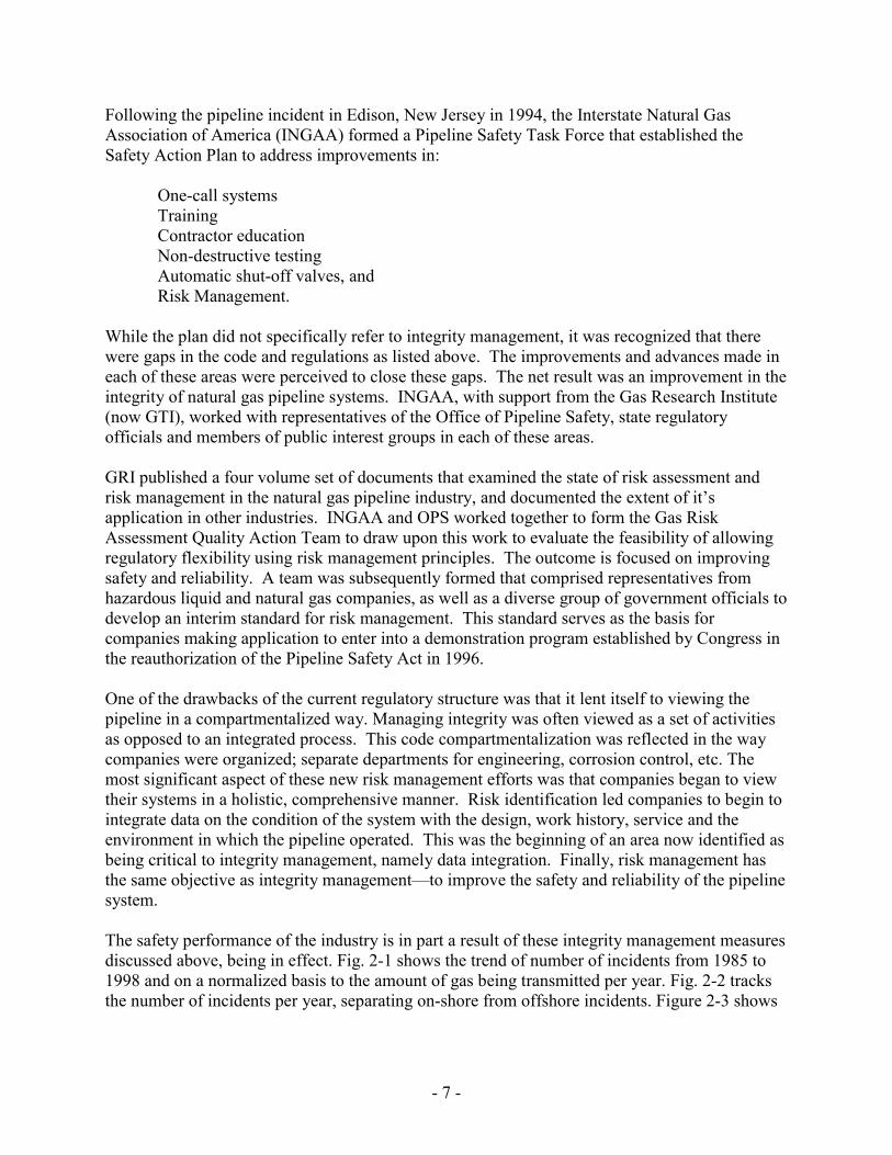
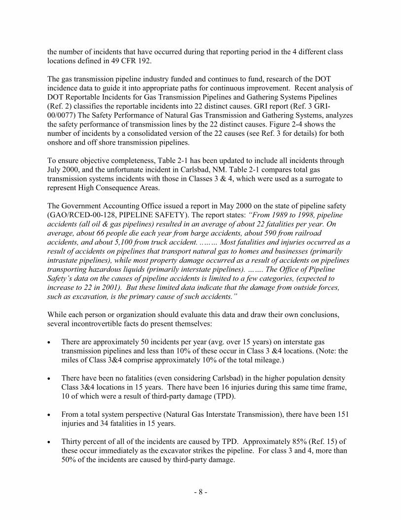


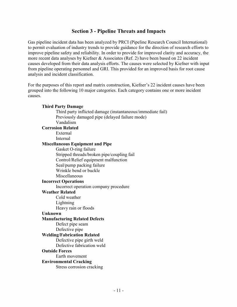


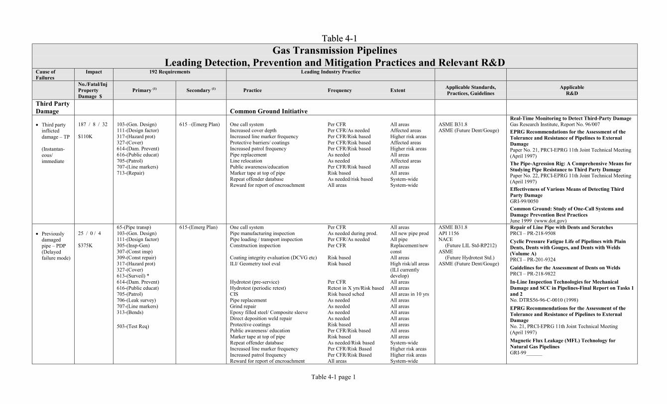


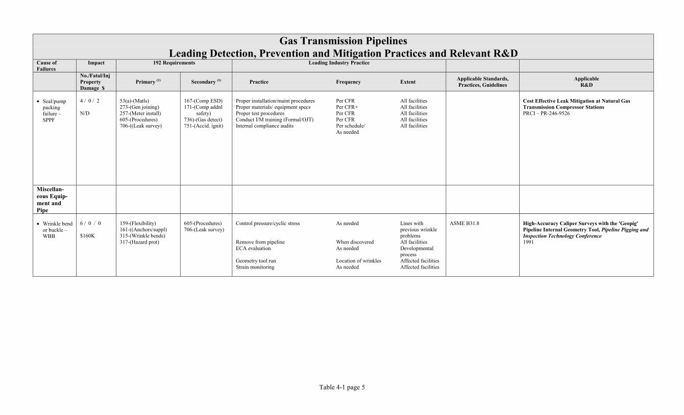
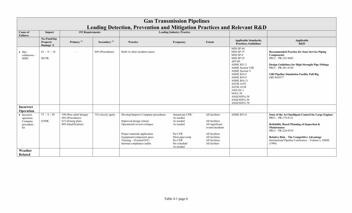
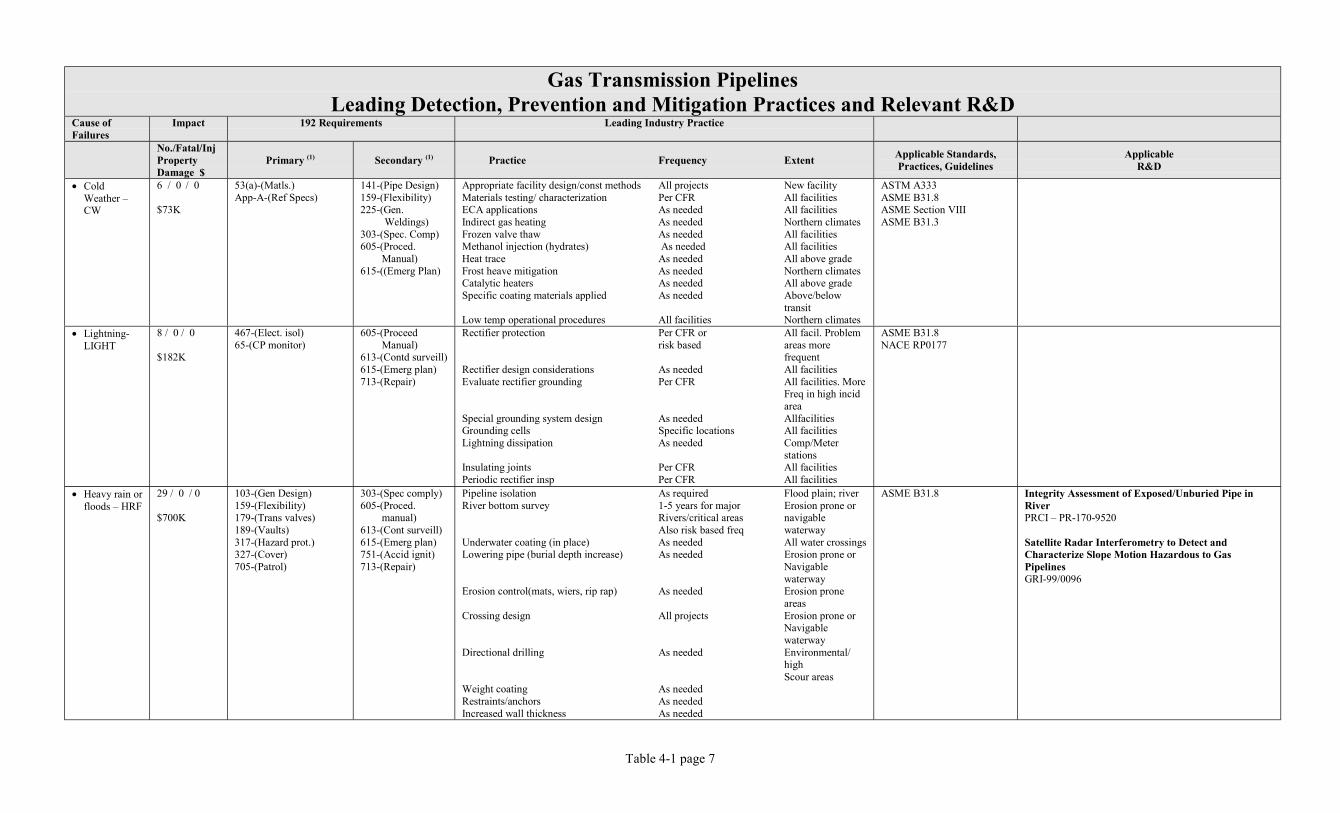
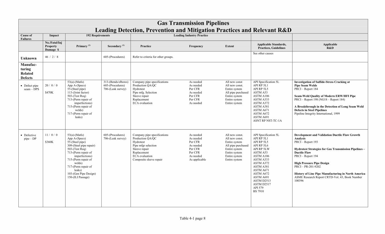

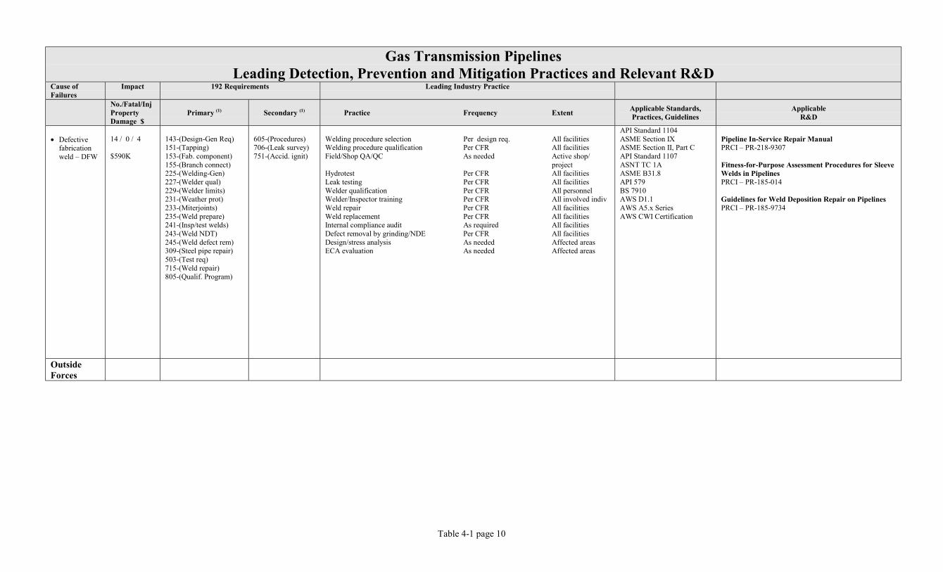

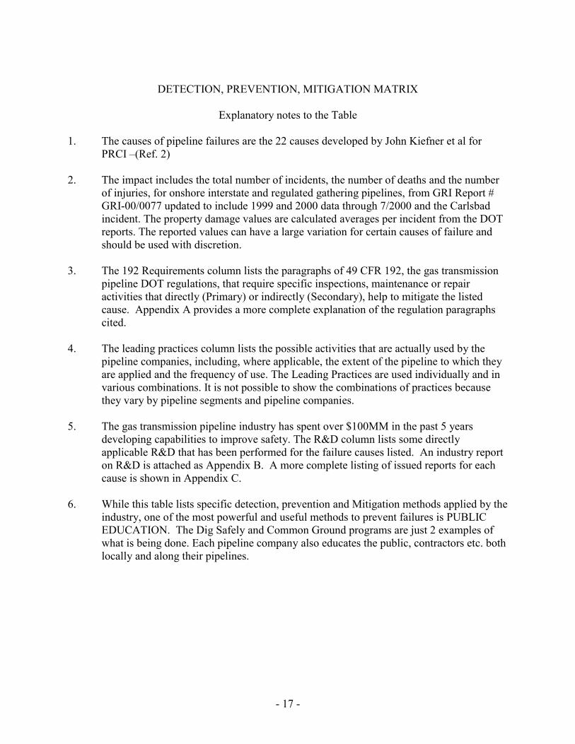


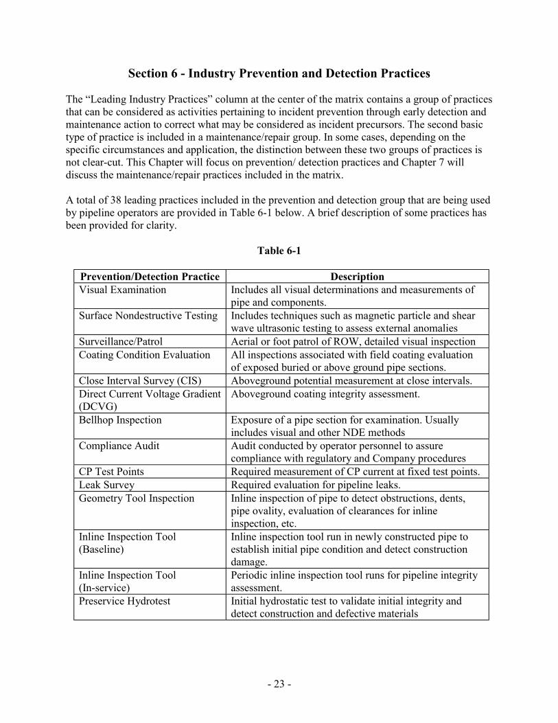
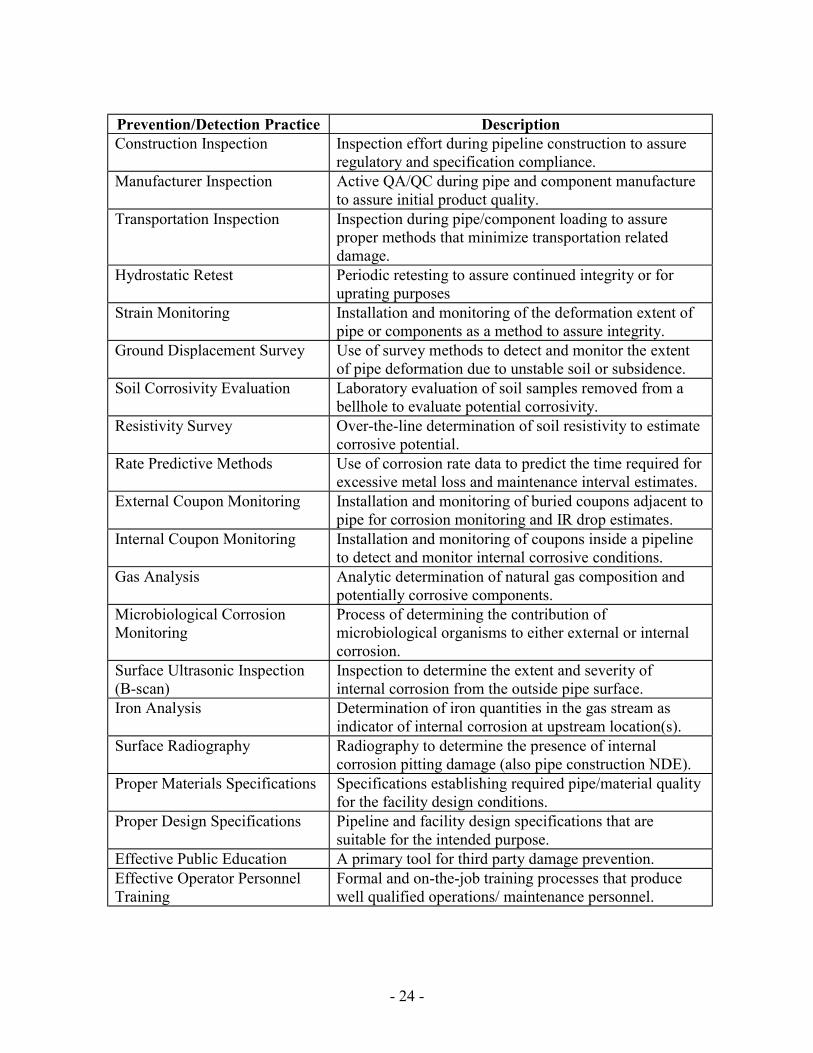


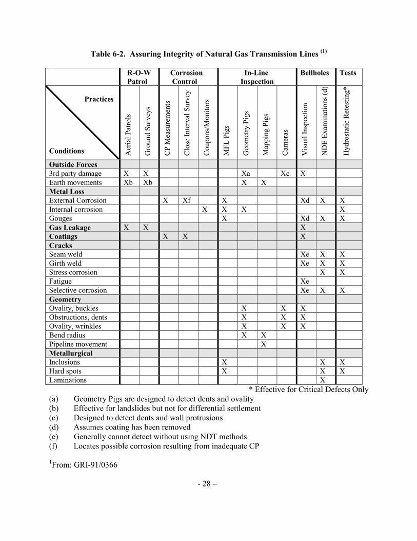
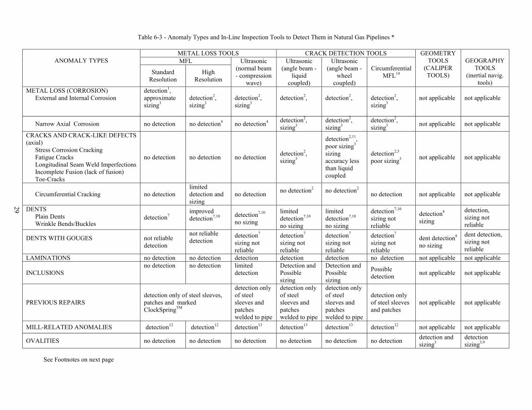


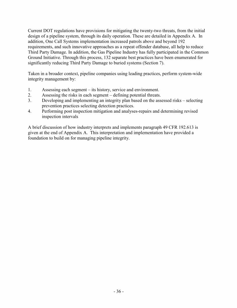
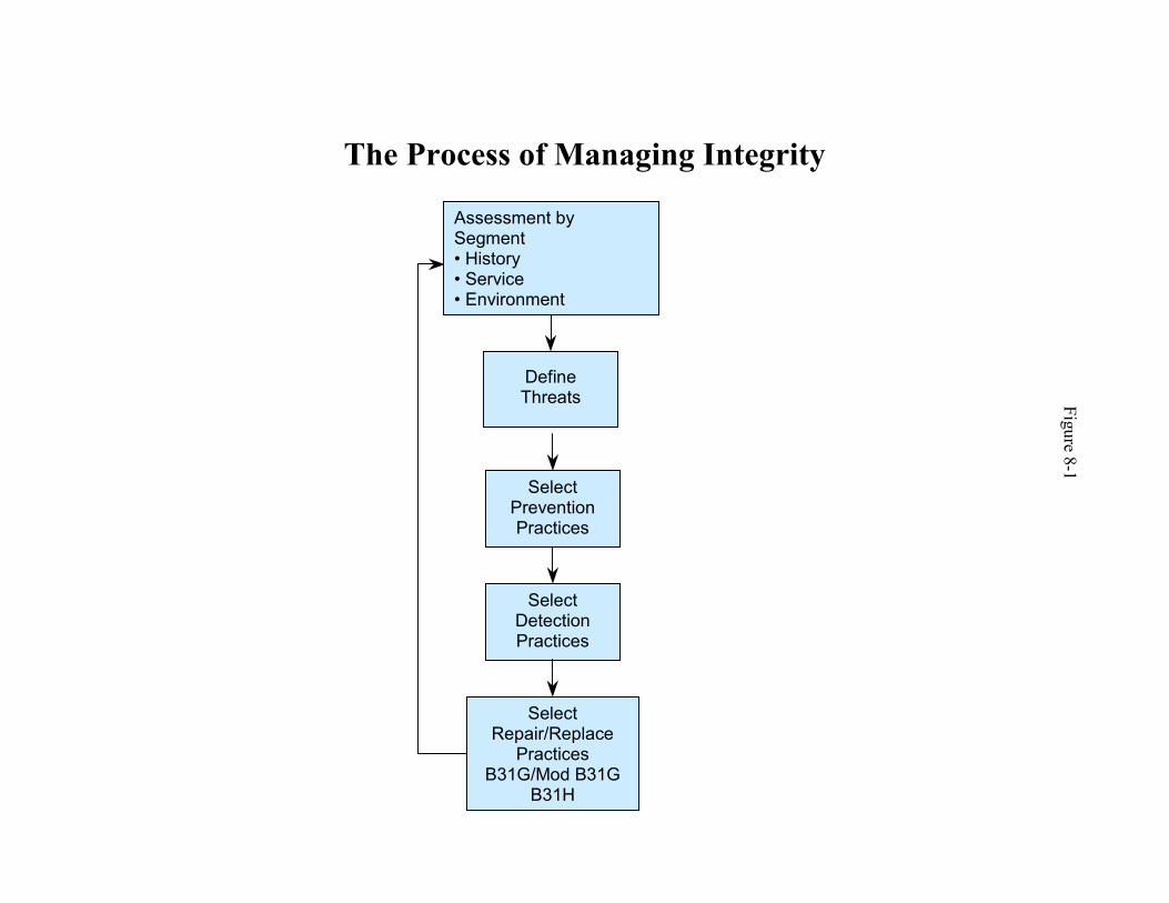


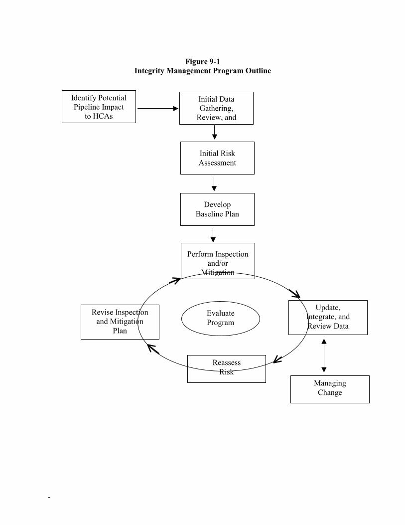

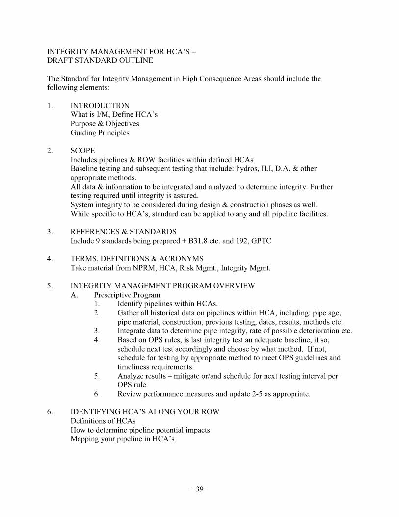


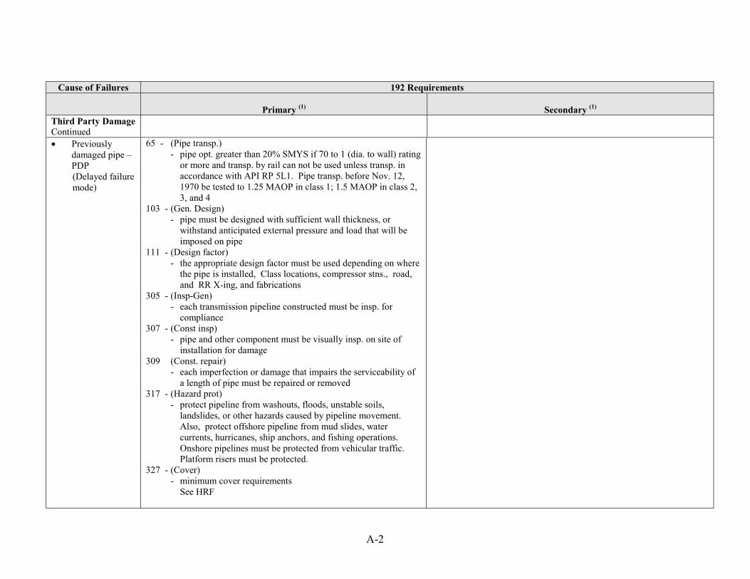
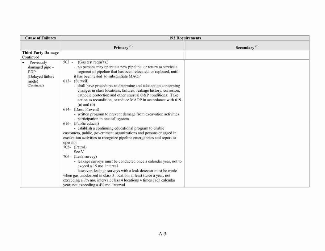


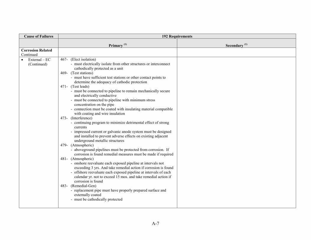
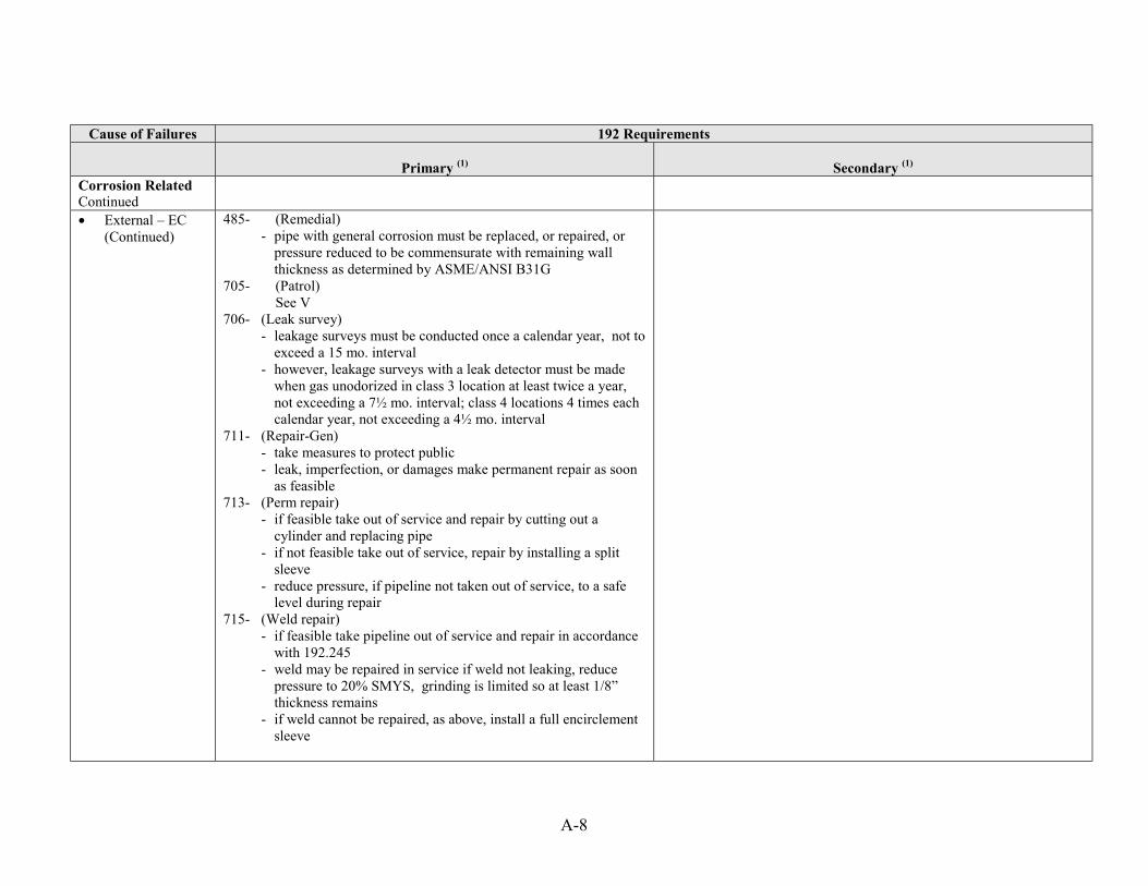
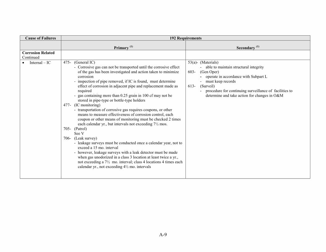
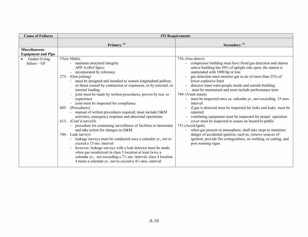

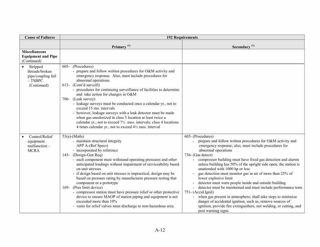


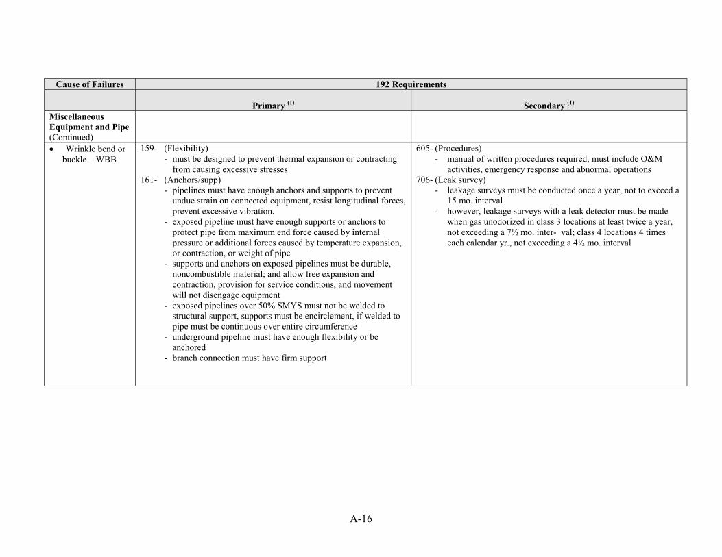


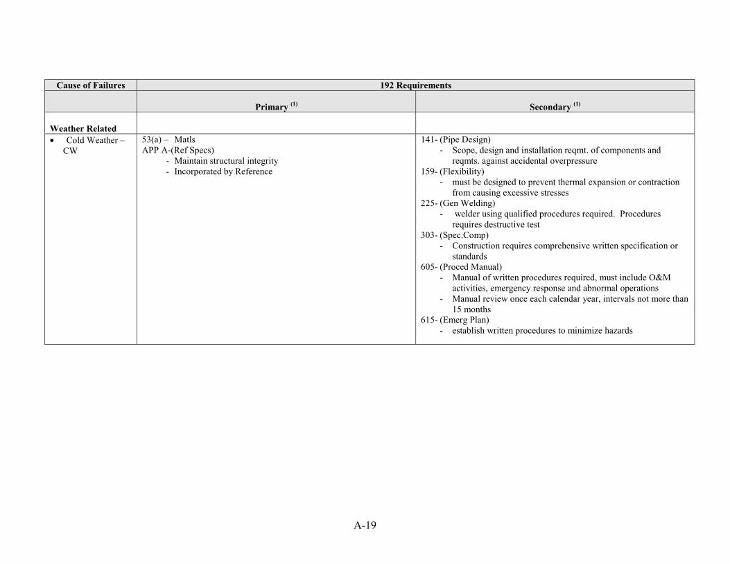
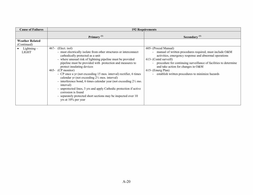


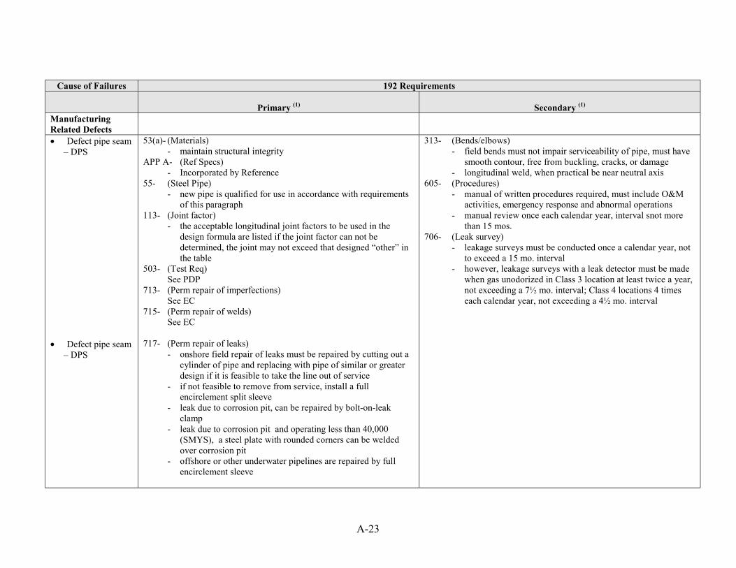
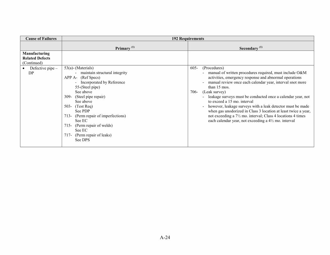


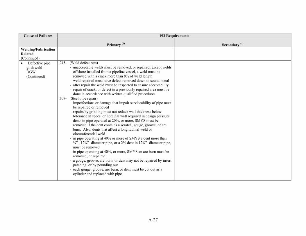
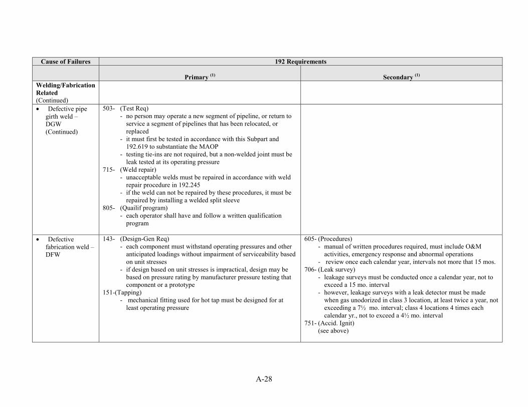
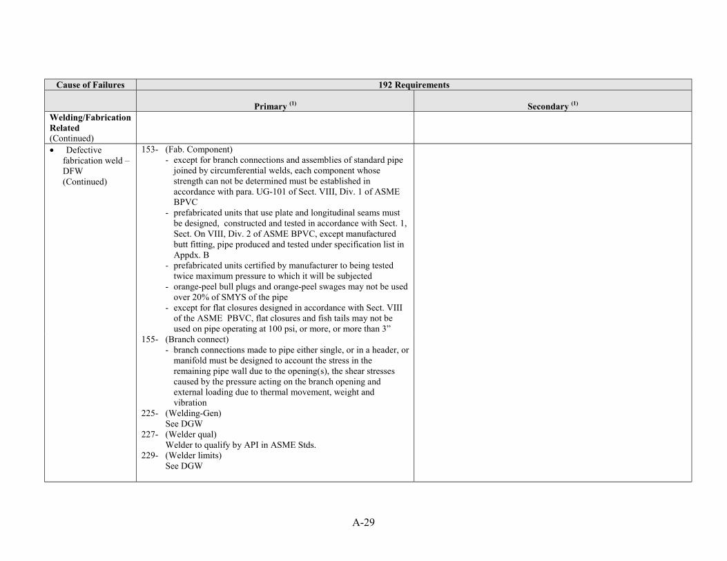
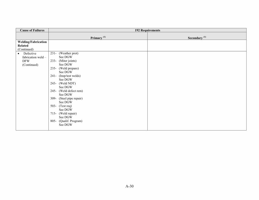


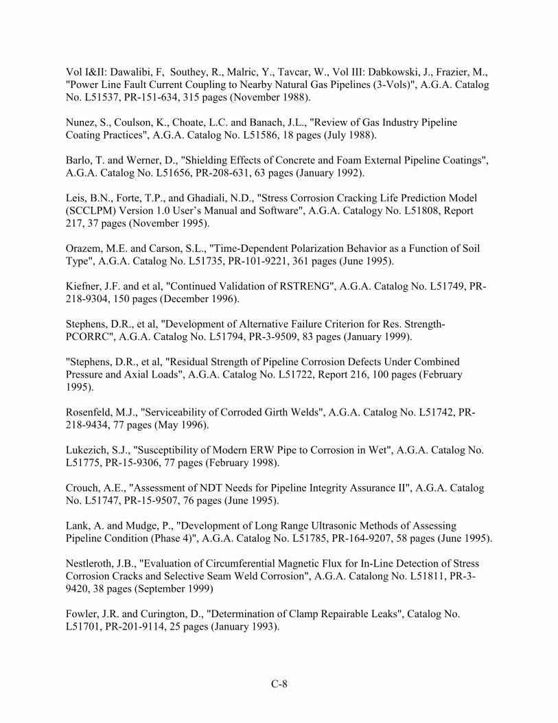
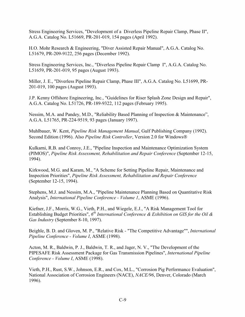

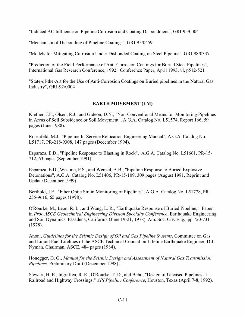


![[Pipeline] Inspecting Pipeline Installation](https://static.documents.pub/doc/80x56/55cf8d045503462b1391543e/pipeline-inspecting-pipeline-installation.jpg)


