Specifications Wingspan: 62 in (1575mm) Length: 41.5 in (1050mm) Wing Area: 550 sq in (35.5 sq dm) Weight w/ Battery: 4–4.25 lb (1800–1900 g) Weight w/o Battery: 3.25 lb (1450 g) Piper Pawnee 15e ARF Assembly Manual
Transcript
SpecificationsWingspan: 62 in (1575mm)Length: 41.5 in (1050mm)Wing Area: 550 sq in (35.5 sq dm)Weight w/ Battery: 4–4.25 lb (1800–1900 g)Weight w/o Battery: 3.25 lb (1450 g)
Piper Pawnee 15e ARFAssembly Manual
2 E-flite Piper Pawnee ARF Assembly Manual
IntroductionThe Piper Pawnee entered service in the late 1950s as one of the first planes to be purpose-built for agricultural spraying and dusting. While most have been retired from crop-dusting duty, many are still on the job today towing advertising banners or serving as towplanes for glider clubs around the world.
E-flite’s Piper Pawnee 15e ARF is a superbly detailed replica of this aerial workhorse that flies every bit as good as it looks. Its fuselage and wing outlines are exact-to-scale and perfectly match the proportions of the full-scale Pawnee. Other realistic touches include the prepainted fiberglass cowl and belly pan as well as cockpit instrument gauges and a pilot’s seat. And like its full-scale inspiration, the Pawnee 15e’s generous wing area gives it exceptionally forgiving flight characteristics that are perfect for newer pilots. You can even outfit the Pawnee 15e with optional flaps and experience exciting short field takeoffs and landings.
Using the ManualThis manual is divided into sections to help make assembly easier to understand, and to provide breaks between each major section. In addition, check boxes have been placed next to each step to keep track of each step completed. Steps with a single circle () are performed once, while steps with two circles ( ) indicate that the step will require repeating, such as for a right or left wing panel, two servos, etc.
Remember to take your time and follow the directions.
Table of ContentsSpecifications ...................................................................... 1Introduction ......................................................................... 2Using the Manual ................................................................ 2Contents of Kit/Parts Layout ................................................. 3Required Radio Equipment ................................................... 3Important Information About Motor Selection ........................ 4Scale Outrunner Setup ......................................................... 4Sport Outrunner Setup ......................................................... 4Optional Accessories ........................................................... 4Required Tools and Adhesives .............................................. 4Notes Regarding Servos and ESC ........................................ 5Note on Lithium Polymer Batteries ........................................ 5Warranty Information ...................................................... 5–7Landing Gear Assembly....................................................... 8Aileron Servo Installation ................................................... 12Flap Servo Installation ....................................................... 19Joining the Wing Panels .................................................... 22Rudder and Elevator Installation ......................................... 25Main Radio Installation ...................................................... 30Motor Installation .............................................................. 37Final Assembly .................................................................. 41Control Throws .................................................................. 43Range Test Your Radio ....................................................... 44Center of Gravity .............................................................. 44Preflight ............................................................................ 45Flying Your Piper Pawnee ARF ........................................... 45Instructions for Disposal of WEEE
by Users in the European Union ............................... 462007 Official AMA
National Model Aircraft Safety Code ....................... 47
3E-flite Piper Pawnee ARF Assembly Manual
Contents of Kit/Parts LayoutEFL2651 Wing Set w/StrutsEFL2652 FuselageEFL2653 Tail SetEFL2654 Landing GearEFL2655 CowlingEFL2656 CanopyEFL2657 Pushrod SetEFL2658 Belly PanEFL2659 Pilot SeatEFL2660 Wing StrutsEFL2661 Battery HatchEFL2662 Motor Mount SpacersEFL2663 Instrument Panel
Required Radio Equipment
You will need a minimum 6-channel transmitter (for proper mixing and dual rate capabilities), crystals, micro receiver, and four mini servos. You can choose to purchase a complete radio system if you are using an existing transmitter, just purchase the other required equipment separately. We recommend the crystal-free, interference-free Spektrum™ DX6i 2.4GHz DSM2® 6-channel full range transmitter and receiver (no servos). If using your own transmitter, we recommend the JR SPORT™ MN48 Mini servos.
If you own the Spektrum DX7 radio, just add the AR7000 DSM2™ 7-channel receiver and four of our JR SPORT MN48 Mini servos.Radio System
JSP20040 MN48 Mini Servo (4)JSP98110 6-inch extension (2)JSP98020 Y harness (1), (2) w/optional flaps
4 E-flite Piper Pawnee ARF Assembly Manual
Important Information About Motor Selection
We recommend the E-flite® Power 15 Brushless Outrunner, 950Kv (EFLM4015A) for sport performance.
Scale Outrunner SetupEFLM4015A Power 15 BL Outrunner, 950KvEFLA1040 40-Amp Brushless ESCTHP42003S2PPL 4200mAh 3-Cell 11.1V Li-PoAPC11070E 11 x 7 Electric PropEFLAEC303 EC3 Device & Battery Connector,
Male/Female (included with our ESC)EFLC3005 Celectra™ 1- to 3-Cell Li-Po Charger
Sport Outrunner SetupEFLM4025A Power 25 BL Outrunner, 870KvEFLA1060 60-Amp Brushless ESCTHP42003S2PPL 4200mAh 3-Cell 11.1 V Li-PoAPC12080E 12 x 8E Electric PropEFLAEC303 EC3 Device & Battery Connector,
Male/Female (included with our ESC)EFLC3005 Celectra 1- to 3-Cell Li-Po Charger
Optional AccessoriesEFLA110 Power Meter
Required Tools and AdhesivesTools & Equipment
EFLA250 Park Flyer Tool Assortment, 5-pieceOr Purchase Separately
EFLA257 Screwdriver, #1 and #2 Phillips (or included with EFLA250)
EFLA251 Hex Wrench: 3/32-inch (or included with EFLA250)
WARNING: Use of servos other than those we recommend may overload the BEC of the recommended Electronic Speed Control (ESC). We suggest the use of only the servos we recommend when utilizing the recommended ESC’s BEC, or the use of a separate BEC (like the UBEC) or receiver battery pack when using other servos.
Note on Lithium Polymer BatteriesLithium Polymer batteries are significantly more volatile than alkaline or Ni-Cd/Ni-MH batteries used in RC applications. All manufacturer’s instructions and warnings must be followed closely. Mishandling of Li-Po batteries can result in fire. Always follow the manufacturer’s instructions when disposing of Lithium Polymer batteries.
WarningAn RC aircraft is not a toy! If misused, it can cause serious bodily harm and damage to property. Fly only in open areas, preferably at AMA (Academy of Model Aeronautics) approved flying sites, following all instructions included with your radio.
Keep loose items that can get entangled in the propeller away from the prop, including loose clothing, or other objects such as pencils and screwdrivers. Especially keep your hands away from the propeller.
Warranty PeriodHorizon Hobby, Inc., (Horizon) warranties that the Products purchased (the “Product”) will be free from defects in materials and workmanship at the date of purchase by the Purchaser.
Limited Warranty(a) This warranty is limited to the original Purchaser ("Purchaser") and is not transferable. REPAIR OR REPLACEMENT AS PROVIDED UNDER THIS WARRANTY IS THE EXCLUSIVE REMEDY OF THE PURCHASER. This warranty covers only those Products purchased from an authorized Horizon dealer. Third party transactions are not covered by this warranty. Proof of purchase is required for warranty claims. Further, Horizon reserves the right to change or modify this warranty without notice and disclaims all other warranties, express or implied.
(b) Limitations- HORIZON MAKES NO WARRANTY OR REPRESENTATION, EXPRESS OR IMPLIED, ABOUT NON-INFRINGEMENT, MERCHANTABILITY OR FITNESS FOR A PARTICULAR PURPOSE OF THE PRODUCT. THE PURCHASER ACKNOWLEDGES THAT THEY ALONE HAVE DETERMINED THAT THE PRODUCT WILL SUITABLY MEET THE REQUIREMENTS OF THE PURCHASER’S INTENDED USE.
(c) Purchaser Remedy- Horizon's sole obligation hereunder shall be that Horizon will, at its option, (i) repair or (ii) replace, any Product determined by Horizon to be defective. In the event of a defect, these are the Purchaser's exclusive remedies. Horizon reserves the right to inspect any and all equipment involved in a warranty claim. Repair or replacement decisions are at the sole discretion of Horizon. This warranty does not cover cosmetic damage or damage due to acts of God, accident, misuse, abuse, negligence, commercial use, or modification of or to any part of the Product. This warranty does not cover damage due to improper installation, operation, maintenance, or attempted repair by anyone other than Horizon. Return of any goods by Purchaser must be approved in writing by Horizon before shipment.
6 E-flite Piper Pawnee ARF Assembly Manual
Damage LimitsHORIZON SHALL NOT BE LIABLE FOR SPECIAL, INDIRECT OR CONSEQUENTIAL DAMAGES, LOSS OF PROFITS OR PRODUCTION OR COMMERCIAL LOSS IN ANY WAY CONNECTED WITH THE PRODUCT, WHETHER SUCH CLAIM IS BASED IN CONTRACT, WARRANTY, NEGLIGENCE, OR STRICT LIABILITY. Further, in no event shall the liability of Horizon exceed the individual price of the Product on which liability is asserted. As Horizon has no control over use, setup, final assembly, modification or misuse, no liability shall be assumed nor accepted for any resulting damage or injury. By the act of use, setup or assembly, the user accepts all resulting liability.
If you as the Purchaser or user are not prepared to accept the liability associated with the use of this Product, you are advised to return this Product immediately in new and unused condition to the place of purchase.
Law: These Terms are governed by Illinois law (without regard to conflict of law principals).
Safety PrecautionsThis is a sophisticated hobby Product and not a toy. It must be operated with caution and common sense and requires some basic mechanical ability. Failure to operate this Product in a safe and responsible manner could result in injury or damage to the Product or other property. This Product is not intended for use by children without direct adult supervision. The Product manual contains instructions for safety, operation and maintenance. It is essential to read and follow all the instructions and warnings in the manual, prior to assembly, setup or use, in order to operate correctly and avoid damage or injury.
Questions, Assistance, and RepairsYour local hobby store and/or place of purchase cannot provide warranty support or repair. Once assembly, setup or use of the Product has been started, you must contact Horizon directly. This will enable Horizon to better answer your questions and service you in the event that you may need any assistance. For questions or assistance, please direct your email to [email protected], or call 877.504.0233 toll free to speak to a service technician.
Inspection or RepairsIf this Product needs to be inspected or repaired, please call for a Return Merchandise Authorization (RMA). Pack the Product securely using a shipping carton. Please note that original boxes may be included, but are not designed to withstand the rigors of shipping without additional protection. Ship via a carrier that provides tracking and insurance for lost or damaged parcels, as Horizon is not responsible for merchandise until it arrives and is accepted at our facility. A Service Repair Request is available at www.horizonhobby.com on the “Support” tab. If you do not have internet access, please include a letter with your complete name, street address, email address and phone number where you can be reached during business days, your RMA number, a list of the included items, method of payment for any non-warranty expenses and a brief summary of the problem. Your original sales receipt must also be included for warranty consideration. Be sure your name, address, and RMA number are clearly written on the outside of the shipping carton.
Warranty Inspection and RepairsTo receive warranty service, you must include your original sales receipt verifying the proof-of-purchase date. Provided warranty conditions have been met, your Product will be repaired or replaced free of charge. Repair or replacement decisions are at the sole discretion of Horizon Hobby.
7E-flite Piper Pawnee ARF Assembly Manual
Non-Warranty RepairsShould your repair not be covered by warranty the repair will be completed and payment will be required without notification or estimate of the expense unless the expense exceeds 50% of the retail purchase cost. By submitting the item for repair you are agreeing to payment of the repair without notification. Repair estimates are available upon request. You must include this request with your repair. Non-warranty repair estimates will be billed a minimum of ½ hour of labor. In addition you will be billed for return freight. Please advise us of your preferred method of payment. Horizon accepts money orders and cashiers checks, as well as Visa, MasterCard, American Express, and Discover cards. If you choose to pay by credit card, please include your credit card number and expiration date. Any repair left unpaid or unclaimed after 90 days will be considered abandoned and will be disposed of accordingly. Please note: non-warranty repair is only available on electronics and model engines.
Electronics and engines requiring inspection or repair should be shipped to the following address:
Horizon Service Center 4105 Fieldstone Road
Champaign, Illinois 61822
All other Products requiring warranty inspection or repair should be shipped to the following address:
Horizon Product Support 4105 Fieldstone Road
Champaign, Illinois 61822
Please call 877-504-0233 with any questions or concerns regarding this product or warranty.
Safety, Precautions, and WarningsAs the user of this product, you are solely responsible for operating it in a manner that does not endanger yourself and others or result in damage to the product or the property of others.
Carefully follow the directions and warnings for this and any optional support equipment (chargers, rechargeable battery packs, etc.) that you use.
This model is controlled by a radio signal that is subject to interference from many sources outside your control. This interference can cause momentary loss of control so it is necessary to always keep a safe distance in all directions around your model, as this margin will help to avoid collisions or injury.
• Always operate your model in an open area away from cars, traffic, or people.
• Avoid operating your model in the street where injury or damage can occur.
• Never operate the model out into the street or populated areas for any reason.
• Never operate your model with low transmitter batteries.
• Carefully follow the directions and warnings for this and any optional support equipment (chargers, rechargeable battery packs, etc.) that you use.
• Keep all chemicals, small parts and anything electrical out of the reach of children.
• Moisture causes damage to electronics. Avoid water exposure to all equipment not specifically designed and protected for this purpose.
8 E-flite Piper Pawnee ARF Assembly Manual
Landing Gear AssemblyRequired Parts
Landing gear Landing gear cover (2)Axle w/nut (2) Instrument panelPilot seat 2mm x 6mm machine screw (4)Landing gear cover (2) 5/64-inch wheel collar w/setscrewVertical Fin Rudder3/4-inch (19mm) tailwheel2mm x 15mm sheet metal screw (8)5/32-inch wheel collar w/setscrew (2)2
1/2-inch (63mm) main wheel w/hubs (2)Required Tools and Adhesives
Note: We will assemble the landing gear and set them aside until needed. This will reduce the number of parts to track, yet keep the fuselage light to install the rudder, elevator and radio system.
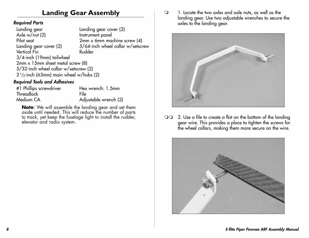
1. Locate the two axles and axle nuts, as well as the landing gear. Use two adjustable wrenches to secure the axles to the landing gear.
2. Use a file to create a flat on the bottom of the landing gear wire. This provides a place to tighten the screws for the wheel collars, making them more secure on the wire.
9E-flite Piper Pawnee ARF Assembly Manual
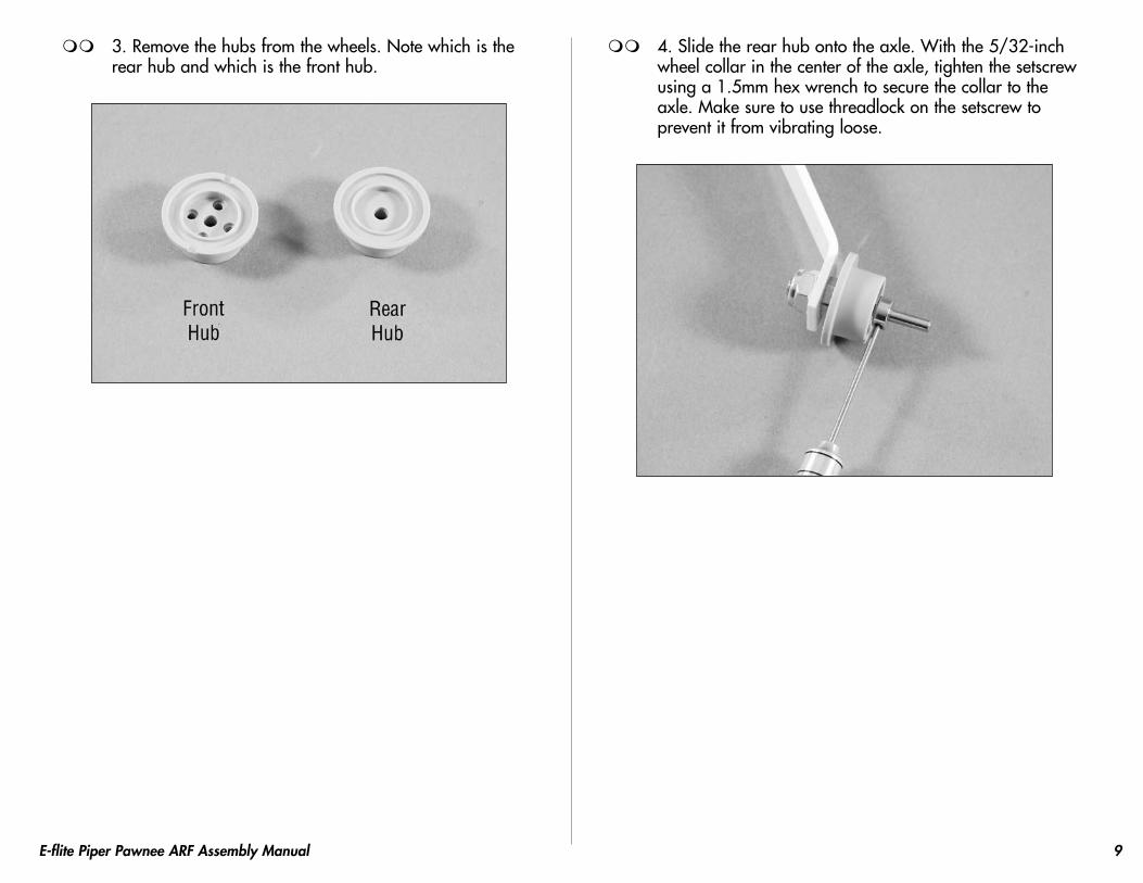
3. Remove the hubs from the wheels. Note which is the rear hub and which is the front hub.
4. Slide the rear hub onto the axle. With the 5/32-inch wheel collar in the center of the axle, tighten the setscrew using a 1.5mm hex wrench to secure the collar to the axle. Make sure to use threadlock on the setscrew to prevent it from vibrating loose.
10 E-flite Piper Pawnee ARF Assembly Manual
5. Slip the tire over the rear hub. Insert the front hub into the tire. Place a piece of music wire or hex wrench through a hole in the front hub and into a screw hole in the rear hub to help align the holes when inserting the front hub in the wheel.
6. Use four 2mm x 15mm sheet metal screws and a #1 Phillips screwdriver to secure the front and rear hubs. You can now install the hubcap onteh wheel.
7. Attach the landing gear covers to the landing gear using four 2mm x 6mm machine screws. Make sure to use threadlock on these screws. The front edge of the covers will line up with the front edge of the landing gear when installed correctly.
11E-flite Piper Pawnee ARF Assembly Manual
8. Repeat Steps 2 through 7 for the remaining wheel installation.
9. Slide the tail wheel onto the tail gear wire. Use a 5/64-inch wheel collar and setscrew to secure the tail wheel. Remember to use threadlock on the setscrew to prevent it from vibrating loose.
10. Use medium CA to glue the instrument panel into the cockpit as shown.
11. Use medium CA to glue the seat into the fuselage.
12 E-flite Piper Pawnee ARF Assembly Manual
Aileron Servo InstallationRequired Parts
Wing panels (right and left)Servo w/hardware (2)Servo cover (right and left)6-inch (152) servo extension (2)2mm x 15mm machine screw (4)2mm x 8mm self-tapping screw (8)Control horn w/backplate (2)Clevis (2)Clevis retainer (2)4-inch (102mm) pushrod wire (2)6-inch (152mm) servo extension (2)Pushrod connector (2)Servo mounting block 5/8 x 3/8 x 3/8-inch (16 x 9.5 x 9.5mm) (4)
1. Plug the aileron servos into the radio system and make sure they operate and are centered as well.
2. Prepare the aileron servos for installation by removing any unnecessary arms from the servo horns as shown. Install any grommets or brass eyelets at this time as well. The servos will have the arms installed opposite of each other as shown in the photo.
3. Position the aileron servo on the servo cover so the arm is centered lengthwise in the cutout. The arm will align with the edge of the servo cover as well. Use a pencil to mark the position of the servo on the cover.
13E-flite Piper Pawnee ARF Assembly Manual
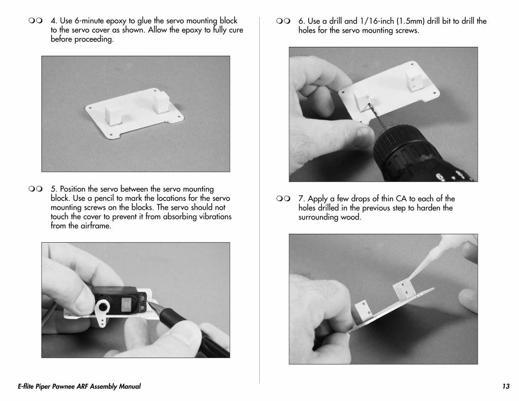
4. Use 6-minute epoxy to glue the servo mounting block to the servo cover as shown. Allow the epoxy to fully cure before proceeding.
5. Position the servo between the servo mounting block. Use a pencil to mark the locations for the servo mounting screws on the blocks. The servo should not touch the cover to prevent it from absorbing vibrations from the airframe.
6. Use a drill and 1/16-inch (1.5mm) drill bit to drill the holes for the servo mounting screws.
7. Apply a few drops of thin CA to each of the holes drilled in the previous step to harden the surrounding wood.
14 E-flite Piper Pawnee ARF Assembly Manual
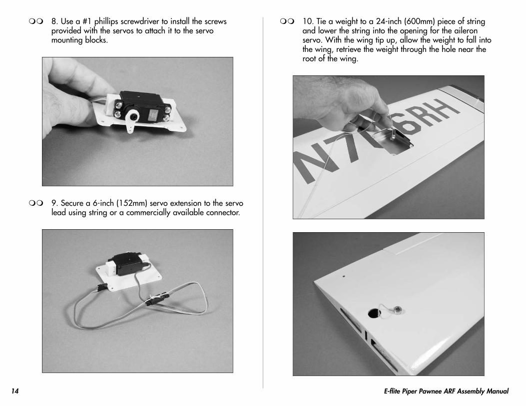
8. Use a #1 phillips screwdriver to install the screws provided with the servos to attach it to the servo mounting blocks.
9. Secure a 6-inch (152mm) servo extension to the servo lead using string or a commercially available connector.
10. Tie a weight to a 24-inch (600mm) piece of string and lower the string into the opening for the aileron servo. With the wing tip up, allow the weight to fall into the wing, retrieve the weight through the hole near the root of the wing.
15E-flite Piper Pawnee ARF Assembly Manual
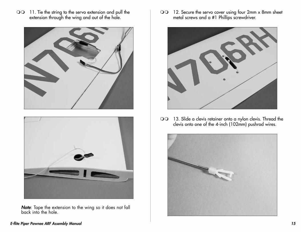
11. Tie the string to the servo extension and pull the extension through the wing and out of the hole.
Note: Tape the extension to the wing so it does not fall back into the hole.
12. Secure the servo cover using four 2mm x 8mm sheet metal screws and a #1 Phillips screwdriver.
13. Slide a clevis retainer onto a nylon clevis. Thread the clevis onto one of the 4-inch (102mm) pushrod wires.
16 E-flite Piper Pawnee ARF Assembly Manual
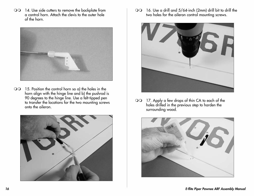
14. Use side cutters to remove the backplate from a control horn. Attach the clevis to the outer hole of the horn.
15. Position the control horn so a) the holes in the horn align with the hinge line and b) the pushrod is 90 degrees to the hinge line. Use a felt-tipped pen to transfer the locations for the two mounting screws onto the aileron.
16. Use a drill and 5/64-inch (2mm) drill bit to drill the two holes for the aileron control mounting screws.
17. Apply a few drops of thin CA to each of the holes drilled in the previous step to harden the surrounding wood.
17E-flite Piper Pawnee ARF Assembly Manual
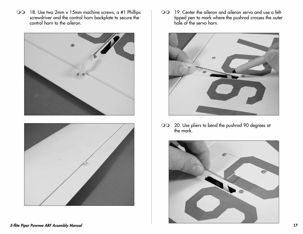
18. Use two 2mm x 15mm machine screws, a #1 Phillips screwdriver and the control horn backplate to secure the control horn to the aileron.
19. Center the aileron and aileron servo and use a felt-tipped pen to mark where the pushrod crosses the outer hole of the servo horn.
20. Use pliers to bend the pushrod 90 degrees at the mark.
18 E-flite Piper Pawnee ARF Assembly Manual
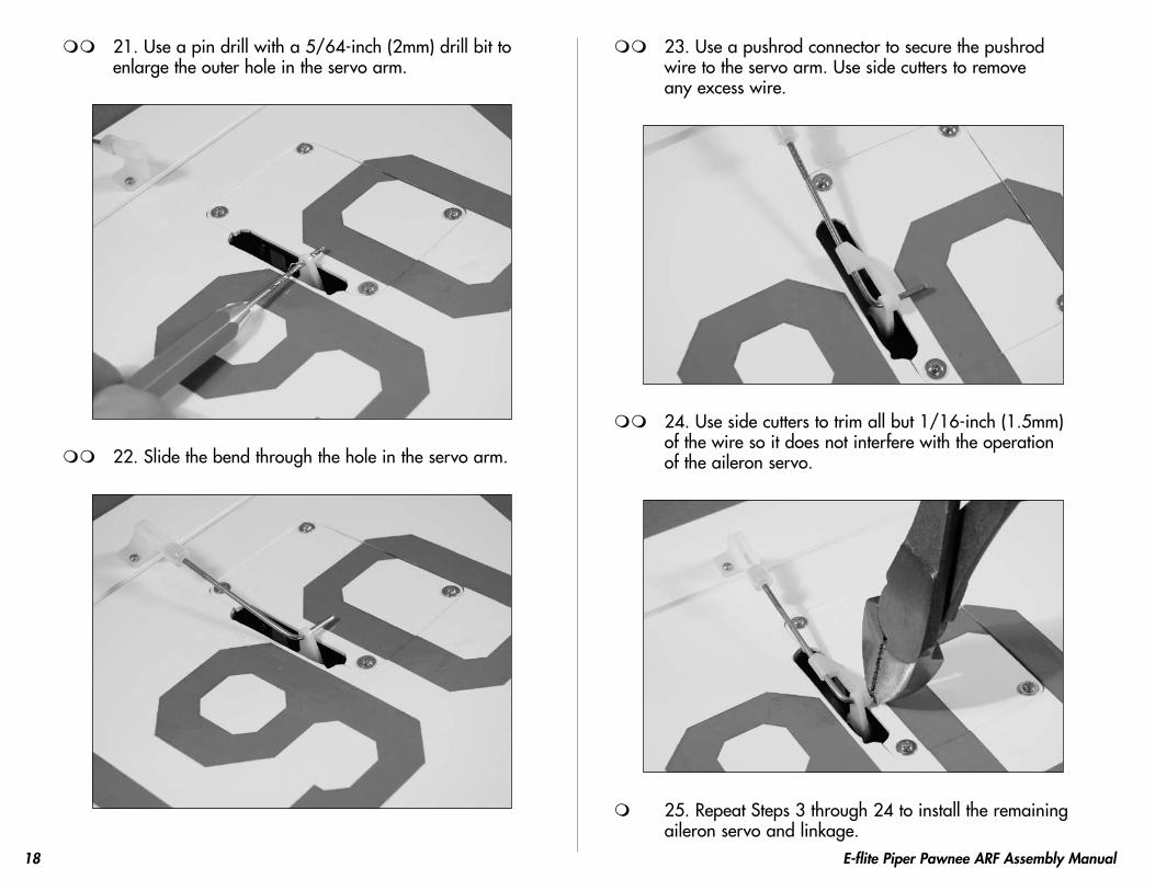
21. Use a pin drill with a 5/64-inch (2mm) drill bit to enlarge the outer hole in the servo arm.
22. Slide the bend through the hole in the servo arm.
23. Use a pushrod connector to secure the pushrod wire to the servo arm. Use side cutters to remove any excess wire.
24. Use side cutters to trim all but 1/16-inch (1.5mm) of the wire so it does not interfere with the operation of the aileron servo.
25. Repeat Steps 3 through 24 to install the remaining aileron servo and linkage.
19E-flite Piper Pawnee ARF Assembly Manual
Flap Servo InstallationRequired Parts
Wing panels (right and left)Servo w/hardware (2)Servo cover (right and left)6-inch (152) servo extension (2)2mm x 15mm machine screw (4)2mm x 8mm self-tapping screw (8)Control horn w/backplate (2)Clevis (2)Clevis retainer (2)4-inch (102mm) pushrod wire (2)Pushrod connector (2)Servo mounting block 5/8 x 3/8 x 3/8-inch (16 x 9.5 x 9.5mm) (4)
Note: The installation of the flaps are optional. You will need to purchase a Y-harness or use a computer radio with mixing to operate the flaps.
1. Plug the flap servos into the radio system and make sure they operate and are centered as well.
20 E-flite Piper Pawnee ARF Assembly Manual
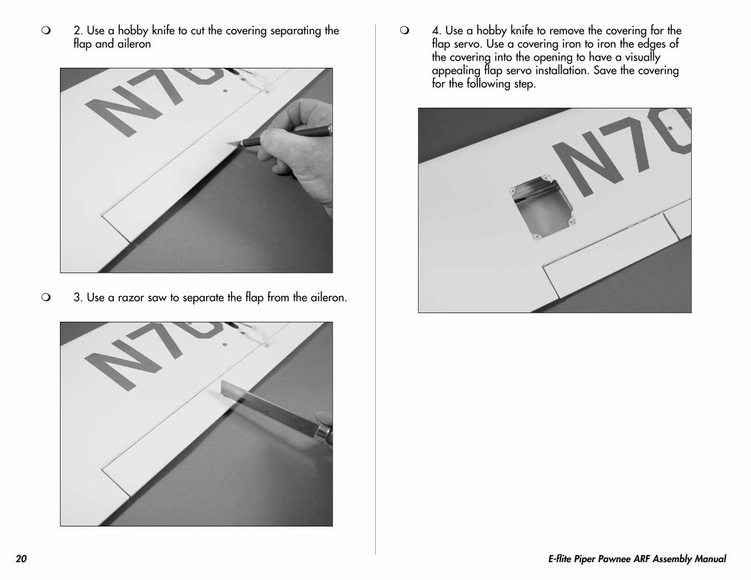
2. Use a hobby knife to cut the covering separating the flap and aileron
3. Use a razor saw to separate the flap from the aileron.
4. Use a hobby knife to remove the covering for the flap servo. Use a covering iron to iron the edges of the covering into the opening to have a visually appealing flap servo installation. Save the covering for the following step.
21E-flite Piper Pawnee ARF Assembly Manual
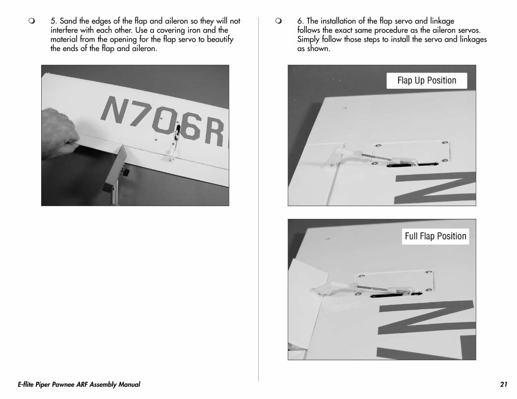
5. Sand the edges of the flap and aileron so they will not interfere with each other. Use a covering iron and the material from the opening for the flap servo to beautify the ends of the flap and aileron.
6. The installation of the flap servo and linkage follows the exact same procedure as the aileron servos. Simply follow those steps to install the servo and linkages as shown.
22 E-flite Piper Pawnee ARF Assembly Manual
Joining the Wing PanelsRequired Parts
Wing panel (right and left) Wing joiner (2)Required Tools and Adhesives
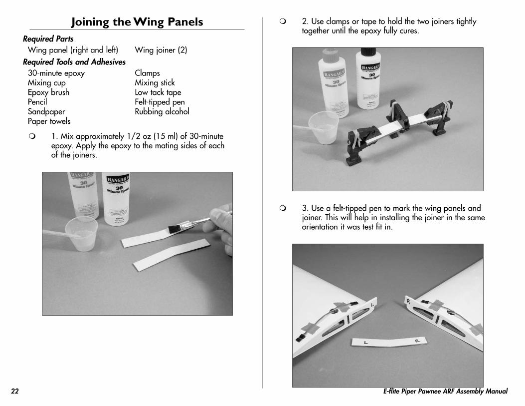
1. Mix approximately 1/2 oz (15 ml) of 30-minute epoxy. Apply the epoxy to the mating sides of each of the joiners.
2. Use clamps or tape to hold the two joiners tightly together until the epoxy fully cures.
3. Use a felt-tipped pen to mark the wing panels and joiner. This will help in installing the joiner in the same orientation it was test fit in.
23E-flite Piper Pawnee ARF Assembly Manual
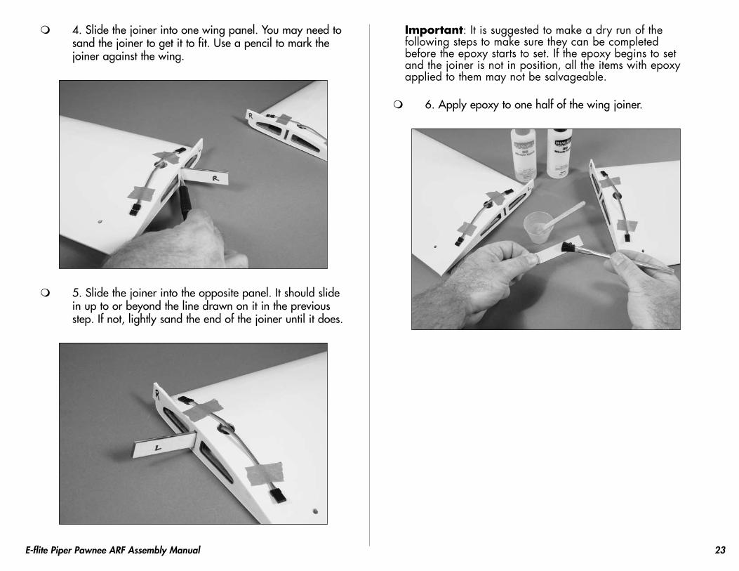
4. Slide the joiner into one wing panel. You may need to sand the joiner to get it to fit. Use a pencil to mark the joiner against the wing.
5. Slide the joiner into the opposite panel. It should slide in up to or beyond the line drawn on it in the previous step. If not, lightly sand the end of the joiner until it does.
Important: It is suggested to make a dry run of the following steps to make sure they can be completed before the epoxy starts to set. If the epoxy begins to set and the joiner is not in position, all the items with epoxy applied to them may not be salvageable.
6. Apply epoxy to one half of the wing joiner.
24 E-flite Piper Pawnee ARF Assembly Manual
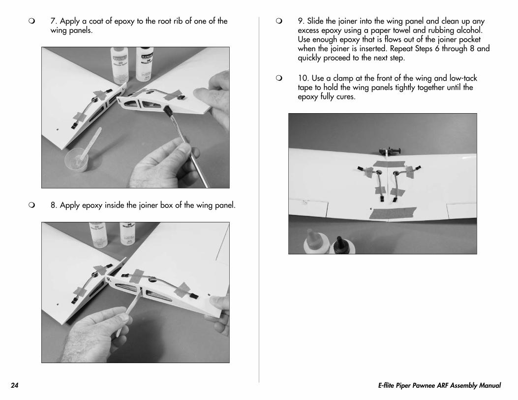
7. Apply a coat of epoxy to the root rib of one of the wing panels.
8. Apply epoxy inside the joiner box of the wing panel.
9. Slide the joiner into the wing panel and clean up any excess epoxy using a paper towel and rubbing alcohol. Use enough epoxy that is flows out of the joiner pocket when the joiner is inserted. Repeat Steps 6 through 8 and quickly proceed to the next step.
10. Use a clamp at the front of the wing and low-tack tape to hold the wing panels tightly together until the epoxy fully cures.
25E-flite Piper Pawnee ARF Assembly Manual
Rudder and Elevator InstallationRequired Parts
Fuselage WingWing fairing 8-32 x 1-inch machine screw (2)#8 washer (2) StabilizerElevator (2) CA hinge (6)
Required Tools and AdhesivesHobby knife Felt-tipped penRuler T-pinsThin CA Rotary toolDrill bit: 1/16-inch (1.5mm) Square30-minute epoxy Phillips screwdriver: #2Medium CA Paper towelRubbing alcohol
1. Attach the wing using two 8-32 x 1-inch machine screws, two #8 washers and a #2 Phillips screwdriver.
2. Use medium CA to glue the wing fairing to the bottom of the wing. Use care not to glue the wing to the fuselage.
3. Measure and mark a center line on one side of the stabilizer. This will help in the alignment.
26 E-flite Piper Pawnee ARF Assembly Manual
4. Position the stabilizer into the slot in the aft end of the fuselage. Check that the stabilizer is centered in the fuselage.
5. View the airframe from the rear and make sure the wing and stab are parallel. If not, lightly sand the stab saddle until they are.
Align Wing and Stabilizer
6. Double-check the adjustments from Steps 1 through 3. Use a felt-tipped pen to trace the outline of the fuselage onto the top and bottom of the stabilizer.
7. Use a sharp hobby knife to cut the covering slightly inside the lines drawn. Be very careful not to cut into the underlying wood, as this will weaken the stab and cause it to fail in flight.
27E-flite Piper Pawnee ARF Assembly Manual
Note: You can use a soldering iron instead of a knife. This will eliminate the chances of cutting into the wood.
8. Apply a thin coat of 30-minute epoxy to the exposed wood on the top and bottom of the stabilizer. Slide the stabilizer back into the fuselage and clean up any excess epoxy using a paper towel and rubbing alcohol.
9. Use a rotary tool and a 1/16-inch (1.5mm) drill bit to drill a hole in the center of each hinge slot of both the stabilizer and elevators. This provides a tunnel for the CA to wick into, penetrating the hinge.
10. Locate three CA hinges. Place a T-pin in the center of each hinge.
28 E-flite Piper Pawnee ARF Assembly Manual
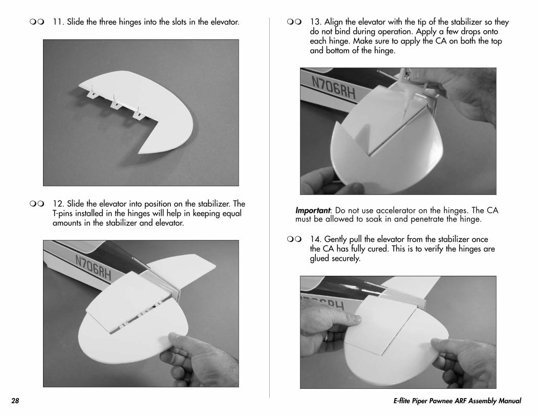
11. Slide the three hinges into the slots in the elevator.
12. Slide the elevator into position on the stabilizer. The T-pins installed in the hinges will help in keeping equal amounts in the stabilizer and elevator.
13. Align the elevator with the tip of the stabilizer so they do not bind during operation. Apply a few drops onto each hinge. Make sure to apply the CA on both the top and bottom of the hinge.
Important: Do not use accelerator on the hinges. The CA must be allowed to soak in and penetrate the hinge.
14. Gently pull the elevator from the stabilizer once the CA has fully cured. This is to verify the hinges are glued securely.
29E-flite Piper Pawnee ARF Assembly Manual
15. Flex the stabilizer through its range of motion a few times to break in the hinges.
16. Repeat Steps 10 through 15 to attach the remaining elevator to the stabilizer.
17. Place the fin in position on the fuselage. Trace the outline of the fuselage onto both sides of the fin.
18. Remove the covering from the bottom of the fin using the same technique used for the stabilizer.
30 E-flite Piper Pawnee ARF Assembly Manual
19. Position the fin back onto the fuselage. Use a square to check the alignment between the fin and stabilizer. Lightly sand the bottom of the fin until the alignment is correct. Use 30-minute epoxy to glue the fin to the fuselage. Make sure to check the alignment periodically to make sure it does not change position during the curing process.
Main Radio InstallationRequired Parts
Receiver Servo w/hardware (3)Pushrod connector (3) Hook and loop material
Required Tools and AdhesivesPhillips screwdriver: #1 ScissorsPliers Side cutters6 minute epoxy Felt-tipped penThin CA Hobby KnifeDrillDrill bit: 1/16-inch (1.5mm), 5/64-inch (2mm)
1. Turn on your radio system and select a new model if using a computer radio. Make sure all the sub-trims have been set to 0 and no mixing functions are turned on. Center the trim levers and stick at this time as well. Plug the servos into the radio system and make sure all servos operate and are centered.
2. Prepare the rudder and elevator servos for installation by removing any unnecessary arms from the servo horns as shown. Install any grommets or brass eyelets at this time.
31E-flite Piper Pawnee ARF Assembly Manual
3. Slide each of the 23 5/8-inch (600mm) pushrods
into the tubes inside the fuselage. You will need to use a hobby knife to trim the covering near the tail so the pushrods can exit the fuselage.
4. Position the rudder servo in the fuselage. Mark the locations for the servo mounting screws on the servo mounting rails using a felt-tipped pen.
32 E-flite Piper Pawnee ARF Assembly Manual
5. Use a drill and 1/16-inch (1.5mm) drill bit to drill the four holes for the servo mounting screws.
6. Apply a few drops of thin CA to each of the holes drilled in the previous step to harden the surrounding wood.
7. Mount the servo using the screws provided with the servo and a #1 Phillips screwdriver.
8. Repeat Steps to install the elevator servo.
33E-flite Piper Pawnee ARF Assembly Manual
9. Use hook and loop tape to install the receiver in the fuselage following the manufacturer's instructions. A tube has been installed inside the fuselage to route the antenna wire. Do not cut the receiver wire if it extends excessively outside the fuselage as this will greatly reduce the range of your radio system.
10. Place a clevis retainer onto a nylon clevis, then thread the clevis onto the rudder pushrod.
11. Remove the backplate from a control horn and attach the horn to the clevis. Position the clevis in a similar fashion as the aileron horn and mark the locations for the two mounting screws.
12. Use a drill and 5/64-inch (2mm) drill bit to drill the two holes for the mounting screws.
34 E-flite Piper Pawnee ARF Assembly Manual
13. Apply a few drops of thin CA to each of the holes drilled in the previous step to harden the surrounding wood.
14. Mount the rudder control horn using a #1 phillips screwdriver and two 2mm x 15mm machine screws.
15. Use a felt-tipped pen to mark the pushrod where it crosses the outer hole of the rudder servo arm.
16. Bend the pushrod wire 90-degrees at the mark made in the previous step.
35E-flite Piper Pawnee ARF Assembly Manual
17. Use a pushrod connector to secure the pushrod wire to the servo arm. Use side cutters to remove any excess wire.
18. Repeat Steps 10 through 17 to install the first elevator pushrod. Before connecting the pushrod to the servo arm, make sure to slide two 5/32-inch wheel collars onto the pushrod wire inside the fuselage as shown.
36 E-flite Piper Pawnee ARF Assembly Manual
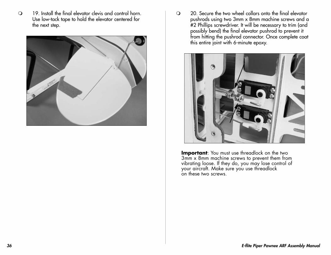
19. Install the final elevator clevis and control horn. Use low-tack tape to hold the elevator centered for the next step.
20. Secure the two wheel collars onto the final elevator pushrods using two 3mm x 8mm machine screws and a #2 Phillips screwdriver. It will be necessary to trim (and possibly bend) the final elevator pushrod to prevent it from hitting the pushrod connector. Once complete coat this entire joint with 6-minute epoxy.
Important: You must use threadlock on the two 3mm x 8mm machine screws to prevent them from vibrating loose. If they do, you may lose control of your aircraft. Make sure you use threadlock on these two screws.
37E-flite Piper Pawnee ARF Assembly Manual
Motor InstallationRequired Parts
Fuselage Motor w/mount and accessories#4 washer (4) CowlingMotor BatteryElectronic speed control PropellerPlywood X mount spacer (2)Hook and Loop straps (2)2mm x 8mm sheet metal screw (4)4-40 x 3/4-inch socket head screw (4)
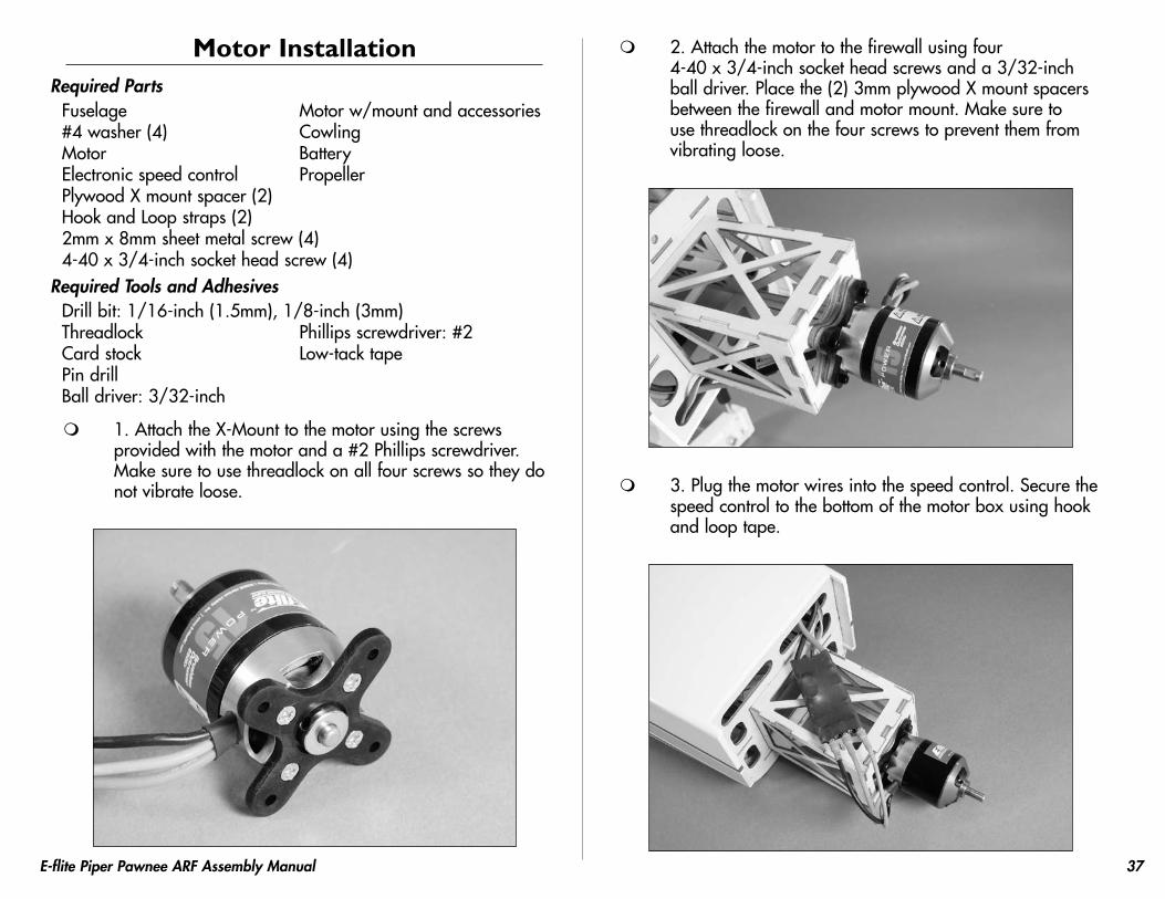
1. Attach the X-Mount to the motor using the screws provided with the motor and a #2 Phillips screwdriver. Make sure to use threadlock on all four screws so they do not vibrate loose.
2. Attach the motor to the firewall using four 4-40 x 3/4-inch socket head screws and a 3/32-inch ball driver. Place the (2) 3mm plywood X mount spacers between the firewall and motor mount. Make sure to use threadlock on the four screws to prevent them from vibrating loose.
3. Plug the motor wires into the speed control. Secure the speed control to the bottom of the motor box using hook and loop tape.
38 E-flite Piper Pawnee ARF Assembly Manual
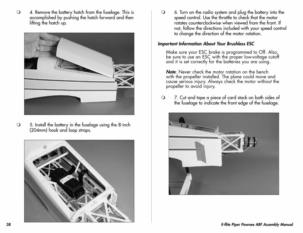
4. Remove the battery hatch from the fuselage. This is accomplished by pushing the hatch forward and then lifting the hatch up.
5. Install the battery in the fuselage using the 8-inch (204mm) hook and loop straps.
6. Turn on the radio system and plug the battery into the speed control. Use the throttle to check that the motor rotates counterclockwise when viewed from the front. If not, follow the directions included with your speed control to change the direction of the motor rotation.
Important Information About Your Brushless ESC
Make sure your ESC brake is programmed to Off. Also, be sure to use an ESC with the proper low-voltage cutoff and it is set correctly for the batteries you are using.
Note: Never check the motor rotation on the bench with the propeller installed. The plane could move and cause serious injury. Always check the motor without the propeller to avoid injury.
7. Cut and tape a piece of card stock on both sides of the fuselage to indicate the front edge of the fuselage.
39E-flite Piper Pawnee ARF Assembly Manual
8. Slide the cowling onto the fuselage.
Important Information About Your Propeller
It is also very important to check to be sure the propeller is balanced before installing onto the shaft. An unbalanced propeller may strip the gears or cause poor flight characteristics.
Note: If it is necessary to enlarge the hole in the propeller, make sure to check the balance of the propeller afterwards.
9. Slide the propeller and adapter onto the motor shaft.
10. Position the cowling so it will not be rubbing on the propeller when the motor is running. Tape the cowling in position on the fuselage.
40 E-flite Piper Pawnee ARF Assembly Manual
11. Use a pin drill and 1/16-inch (1.5mm) drill bit to drill four locations (two each side) for the cowl mounting screws.
Note: Ensure the painted stripe on the cowl lines up with the stripe on the fuselage before drilling.
12. Use a pin drill and 1/8-inch (3mm) drill bit to drill the four holes in the cowling for the mounting screws.
13. Apply a few drops of thin CA to each of the holes drilled in the previous step to harden the surrounding wood.
14. Secure the cowl to the fuselage using four 2mm x 8mm sheet metal screws. Secure the propeller to the motor.
41E-flite Piper Pawnee ARF Assembly Manual
Final AssemblyRequired Parts
Fuselage WingWing strut (2) 2mm x 12mm sheet metal screw (6)Canopy Y-harness (2)6-32 x 1/2-inch socket head screw (2)
Required Tools and AdhesivesCanopy glue Phillips screwdriver: #1, #2Low-tack masking tape Hex wrench: 7/64-inchThreadlock Hobby knifeMedium CA1/16-inch (1.5mm) drill bit or T-pin
1. Use a hobby knife to remove the covering to expose the blind nuts for the landing gear.
2. Attach the landing gear to the fuselage using two 6-32 x 1/2-inch socket head screws and a 7/64-inch hex wrench. Use threadlock on the screws to prevent them from vibrating loose in flight.
42 E-flite Piper Pawnee ARF Assembly Manual
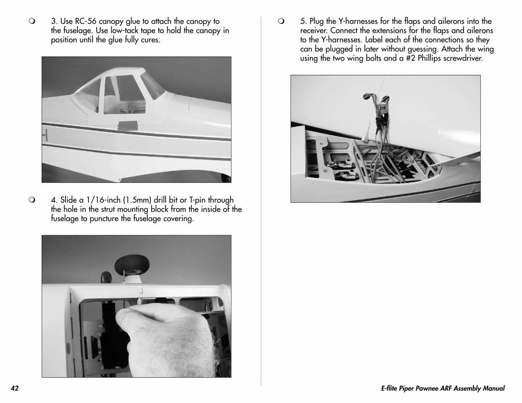
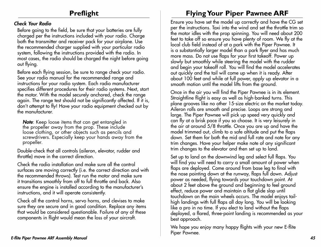
3. Use RC-56 canopy glue to attach the canopy to the fuselage. Use low-tack tape to hold the canopy in position until the glue fully cures.
4. Slide a 1/16-inch (1.5mm) drill bit or T-pin through the hole in the strut mounting block from the inside of the fuselage to puncture the fuselage covering.
5. Plug the Y-harnesses for the flaps and ailerons into the receiver. Connect the extensions for the flaps and ailerons to the Y-harnesses. Label each of the connections so they can be plugged in later without guessing. Attach the wing using the two wing bolts and a #2 Phillips screwdriver.
43E-flite Piper Pawnee ARF Assembly Manual
6. Test fit the struts between the fuselage and wing. They can be turned over (top to bottom) if they do not align with the holes in the wing and fuselage. Secure the strut to the fuselage using a 2mm x 12mm sheet metal screw and #1 Phillips screwdriver.
7. Secure the struts to the wing using two 2mm x 12mm sheet metal screws and #1 Phillips screwdriver.
Control Throws 1. Turn on the transmitter and receiver of your Piper Pawnee.
Check the movement of the rudder using the transmitter. When the stick is moved right, the rudder should also move right. Reverse the direction of the servo at the transmitter if necessary.
2. Check the movement of the elevator with the radio system. Moving the elevator stick down will make the airplane elevator move up.
3. Check the movement of the ailerons with the radio system. Moving the aileron stick right will make the right aileron move up and the left aileron move down.
4. Use a ruler to adjust the throw of the elevator, ailerons and rudder. Adjust the position of the pushrod at the control horn to achieve the following measurements when moving the sticks to their endpoints.
Note: Measurements are taken at the widest point on the surface.
AileronsHigh Rate: 1-inch (25mm) (Up/Down)
Low Rate: 5/8-inch (15mm) (Up/Down)
ElevatorHigh Rate: 2-inch (51mm) (Up/Down)
Low Rate: 1 1/4-inch (32mm) (Up/Down)
RudderHigh Rate: 3-inch (76mm) (Right/Left)
Low Rate: 2-inch (51mm) (Right/Left)
These are general guidelines measured from our own flight tests. You can experiment with higher rates to match your preferred style of flying.
44 E-flite Piper Pawnee ARF Assembly Manual
Once all the control throws have been set, make sure to slide the clevis retainers over the clevises to prevent them from opening accidentally.
Range Test Your Radio 1. Before each flying session, be sure to range check your
radio. This is accomplished by turning on your transmitter with the antenna collapsed. Turn on the receiver in your airplane. With your airplane on the ground and the engine running, you should be able to walk 30 paces (approximately 100 feet) away from your airplane and still have complete control of all functions.
If not, don’t attempt to fly! Have your radio equipment checked out by the manufacturer.
2. Double-check that all controls (aileron, elevator, rudder and throttle) move in the correct direction.
3. Be sure that your transmitter batteries are fully charged, per the instructions included with your radio.
Center of GravityAn important part of preparing the aircraft for flight is properly balancing the model.
Caution: Do not inadvertently skip this step!
The recommended Center of Gravity (CG) location for the Piper Pawnee ARF is 2
1/4– 2 3/4-inch (57–70mm) back from the
leading edge on the top of the wing. Support the model inverted on the marks to check the balance.
After the first flights, the CG position can be adjusted for your personal preference.
45E-flite Piper Pawnee ARF Assembly Manual
PreflightCheck Your Radio
Before going to the field, be sure that your batteries are fully charged per the instructions included with your radio. Charge both the transmitter and receiver pack for your airplane. Use the recommended charger supplied with your particular radio system, following the instructions provided with the radio. In most cases, the radio should be charged the night before going out flying.
Before each flying session, be sure to range check your radio. See your radio manual for the recommended range and instructions for your radio system. Each radio manufacturer specifies different procedures for their radio systems. Next, start the motor. With the model securely anchored, check the range again. The range test should not be significantly affected. If it is, don’t attempt to fly! Have your radio equipment checked out by the manufacturer.
Note: Keep loose items that can get entangled in the propeller away from the prop. These include loose clothing, or other objects such as pencils and screwdrivers. Especially keep your hands away from the propeller.
Double-check that all controls (aileron, elevator, rudder and throttle) move in the correct direction.
Check the radio installation and make sure all the control surfaces are moving correctly (i.e. the correct direction and with the recommended throws). Test run the motor and make sure it transitions smoothly from off to full throttle and back. Also ensure the engine is installed according to the manufacturer’s instructions, and it will operate consistently.
Check all the control horns, servo horns, and clevises to make sure they are secure and in good condition. Replace any items that would be considered questionable. Failure of any of these components in flight would mean the loss of your aircraft.
Flying Your Piper Pawnee ARFEnsure you have set the model up correctly and have the CG set per the instructions. Taxi into the wind and set the throttle trim so the motor idles with the prop spinning. You will need about 200 feet to take off so ensure you have plenty of room. We fly at the local club field instead of at a park with the Piper Pawnee. It is a substantially larger model than a park flyer and has much more mass. Do not use flaps for your first takeoff. Power up slowly but smoothly while steering the model with the rudder and begin your takeoff roll. You will find the model accelerates out quickly and the tail will come up when it is ready. After about 100 feet and while at full power, apply up elevator in a smooth motion until the model lifts from the ground.
Once in the air you will find the Piper Pawnee is in its element. Straightline flight is easy as well as high-banked turns. This plane grooves like no other 15-size electric on the market today. Aileron rolls are smooth and precise. Loops are strong and large. The Piper Pawnee will pick up speed very quickly and can fly at a brisk pace if you so choose. It is very leisurely in the air at around 5/8 throttle. Once you are up and have the model trimmed out, climb to a safe altitude and put the flaps down. Set them for both the mid and full rate and note for any trim changes. Have your helper make note of any significant trim changes to the elevator and then set up to land.
Set up to land on the downwind leg and select full flaps. You will find you will need to carry a small amount of power when flaps are deployed. Come around from base leg to final with the nose pointing down at the runway, flaps full down. Adjust power as needed, flying towards your touchdown point. At about 2 feet above the ground and beginning to feel ground effect, reduce power and maintain a flat glide slop until touchdown on the main wheels occurs. The model enjoys tail-high landings with full flaps all day long. You will be looking like a pro in no time. If you elect to land without the flaps deployed, a flared, three-point landing is recommended as your best approach.
We hope you enjoy many happy flights with your new E-flite Piper Pawnee.
46 E-flite Piper Pawnee ARF Assembly Manual
Instructions for Disposal of WEEE by Users in the European Union
This product must not be disposed of with other waste. Instead, it is the user’s responsibility to dispose of their waste equipment by handing it over to a designated collection point for the recycling of waste electrical and electronic equipment. The separate collection and recycling of your waste equipment at the time of disposal will help to conserve natural resources and ensure that it is recycled in a manner that protects human health and the environment. For more information about where you can drop off your waste equipment for recycling, please contact your local city office, your household waste disposal service or where you purchased the product.
47E-flite Piper Pawnee ARF Assembly Manual
2007 Official AMA National Model Aircraft Safety Code
GENERAL1) I will not fly my model aircraft in sanctioned events, air shows
or model flying demonstrations until it has been proven to be airworthy by having been previously, successfully flight tested.
2) I will not fly my model higher than approximately 400 feet within 3 miles of an airport without notifying the airport operator. I will give right-of-way and avoid flying in the proximity of full-scale aircraft. Where necessary, an observer shall be utilized to supervise flying to avoid having models fly in the proximity of full-scale aircraft.
3) Where established, I will abide by the safety rules for the flying site I use, and I will not willfully or deliberately fly my models in a careless, reckless and/or dangerous manner.
4) The maximum takeoff weight of a model is 55 pounds, except models flown under Experimental Aircraft rules.
5) I will not fly my model unless it is identified with my name and address or AMA number on or in the model. (This does not apply to models while being flown indoors.)
6) I will not operate models with metal-bladed propellers or with gaseous boosts, in which gases other than air enter their internal combustion engine(s); nor will I operate models with extremely hazardous fuels such as those containing tetranitromethane or hydrazine.
RADIO CONTROL1) I will have completed a successful radio equipment ground range
check before the first flight of a new or repaired model.2) I will not fly my model aircraft in the presence of spectators until I
become a qualified flier, unless assisted by an experienced helper.3) At all flying sites a straight or curved line(s) must be established
in front of which all flying takes place with the other side for spectators. Only personnel involved with flying the aircraft are allowed at or in front of the flight line. Intentional flying behind the flight line is prohibited.
4) I will operate my model using only radio control frequencies currently allowed by the Federal Communications Commission. (Only properly licensed Amateurs are authorized to operate equipment on Amateur Band frequencies.)
5) Flying sites separated by three miles or more are considered safe from site-to-site interference, even when both sites use the same frequencies. Any circumstances under three miles separation require a frequency management arrangement, which may be either an allocation of specific frequencies for each site or testing to determine that freedom from interference exists. Allocation plans or interference test reports shall be signed by the parties involved and provided to AMA Headquarters.
Documents of agreement and reports may exist between (1) two or more AMA Chartered Clubs, (2) AMA clubs and individual AMA members not associated with AMA Clubs, or (3) two or more individual AMA members.
6) For Combat, distance between combat engagement line and spectator line will be 500 feet per cubic inch of engine displacement. (Example: .40 engine = 200 feet.); electric motors will be based on equivalent combustion engine size. Additional safety requirements will be per the RC Combat section of the current Competition Regulations.
7) At air shows or model flying demonstrations, a single straight line must be established, one side of which is for flying, with the other side for spectators.
8) With the exception of events flown under AMA Competition rules, after launch, except for pilots or helpers being used, no powered model may be flown closer than 25 feet to any person.
9) Under no circumstances may a pilot or other person touch a powered model in flight.


![[ ] ARF slides.ppt](https://static.documents.pub/doc/80x56/55ca7deabb61eb604e8b456c/-arf-slidesppt.jpg)


