28
NASA SP-5903 (02) TECHNOLOGY UTILIZATION PIPING AND TUBING TECHNOLOGY CASE FI LE COPY A COMPILATION i "_ z' I i.J ,_. '_,, _ .... NATIONAL AERONAUTICS AND SPACE ADMINISTRATION

NASA SP-5903 (02)
TECHNOLOGY UTILIZATION
PIPING AND TUBING TECHNOLOGY
CASE FI LECOPY
A COMPILATION
i "_ z' Ii.J ,_.
'_,, _ ....
NATIONAL AERONAUTICS AND SPACE ADMINISTRATION

II

Foreword
The National Aeronautics and Space Administration has established a
Technology Utilization Program for the dissemination of information on tech-
nological developments which have potential utility outside the aerospace com-
munity. By encouraging multiple application of the results of its research and
development,. NASA earns for the public an increased return on the investment
in aerospace research and development programs.
This publication is part of a series intended to provide such technical informa-
tion. The devices, methods, and techniques presented have resulted from the
gieat variety of requirements that have been encountered in the aerospace pro-
gram. The handling of fluids has encompassed a wide range of materials, and
has covered a spectrum from low to high pressures and from cryogenic to
elevated temperatures.The document is divided into four sections. The first section includes a num-
ber of fittings, couplings, and connectors that have been useful in joining tubing
and piping and various systems. Section two presents a family of devices used
where flexibility' and/or vibration damping are necessary. The third section
contains a number of devices found useful in the regulation and control of fluid
flow. In tile last section, shop hints to aid in maintenance and repair procedures
such as cleaning, flaring and swaging of tubes, etc., are presented.
Additional technical information on individual tools and techniques can be
requested by circling the appropriate number on the Reader Service Card in-
cluded in this compilation.
Unless otherwise stated, NASA contemplates no patent action on the tech-
nology described.
We appreciate comment by readers and welcome hearing about the relevance
and utility of the information in this compilation.
Ronald J. Philips, Director
TechmJlo_y Utilizatimt O/tTce
National Aero_autics and Space AdmilU._tratiou
NOTICE • This document was prepared under the sponsorship of the National Aeronautics, and Space
Administration, Neither the United States Government nor any person acting on behalf of the United
Stales Government assumes an)' liability resulting from the use of the inl't)rmation conl:,lined in lhb,
document, or warrants that such use will be free from privately ov_ned rights.
For sale by the National Technical Information Service. Springfield, Virginia 22151 - Price $1,00

Contents
SECTfON 1. Fittings, Couplings, and Connectors
Pipe Joints Reinforced in Place ',_ith Fitted
Aluminum Sleeves ............................... 1
High Pressure Coupling for Unthreaded, Unflared
Tubes .............. " ......................... 2
Method for Reinforcing Tubing Joints .................. 2
Self-Sealing Fitting for Injection and Samplingof Liquids ........................ ' ............ 3
A Quick Disconnect for Cryogenic Fluid Lines .......... 4
Elbow Fitting with Self-Locking Coupling Nut ............ 4
Lightweight ttose Assembly v,ith High Flexibilityand Strength .................................. 5
Fusible Metal Used in High-Pressure Pipe Joint ............ 6
SECT1OX 2. Flexible Devices and Vibration Damping
Plastic Tubing Protects Flexible Copper Hose ............. 6
Spherical Pipe Joint Loads Mating Flanges Evcnb . ........ 7TFE-Fluorocarbon Liners for Flexible Hoses .............. 7
Flow Liner Extends Operating Lifeof High-Angulation Bellows ........................ 8
Bellows Joint Absorbs Torsional Deflections
in Duct System ................................. 8
Bellows Design Features Low Spring Rate
and Long Life ................................. 9
Universal Gimbal Forms Flexible Tube System ............ 10Vibration Damper for Hydraulic Filter ................. 10
Threaded, Union-Type Gimbal ....................... I l
tligh Flow, High Pressure Gimbal Joint ................ 11
SECTION 3. Devices Used for Regulation and Control
Improved Drag-Type Flowmeler: A Concept .............. 12
Flow Rate Range Controlled by Cavitating Venturi ......... 12Orifice for Automatically Regulating Flow Rate:
A Concept .................................... 13
Pressure Block and Vent with Integral Relief Valve:
A Concept .................................... 13
Automatic Humidity Regulation in Decontamination
System ...................................... 14
Electrically Actuated Burst Disk Assembly ............... 14
Simplified Rupture Diaphragm for Standard Fittings:A Concept .................................... 15

SECTION4.ShopHintsforMaintenanceandRepairTelescopingof InstrumentationTubingEliminatesSwaging..................................... [6
PipeCuttingTool for Usein LimitedSpace.............. 16ImprovedToo[EasilyRemovesBrazedTube Connectors ...... 17
Orbital Tube Flaring System Produces Connectorswith Zero Leakage .............................. 18
Cleaning Method for Bellows Convolutions:
A Concept ................................... 19
Guides Protect Bellows During Pressure Testing ............ 19Improved Technique for Coupling Flexible Tubing
onto Rigid Tubing .............................. 20
Adjustable Saddle Clamp for Tubing ................... 20
Adapter Simplifies Flush Cleaning of Female
Half Couplers ................................. 21Cleaner for Convoluted Hose ........................ 21
i/i


Section 1. Fittings, Couplings, and Connectors
PIPE JOINTS REINFORCED IN PLACE WITH FITTEDALUMINUM SLEEVES
Space for EpoxyTubing Snapring Ferrule Sleeve /
\ I _ _ / Sleeve Swaged\ l \ _k / to Snapring
A new technique can be used to reinfo'rce:
solder-sealed ferrule joints In instaJled small-diam-
eter aluminum tubing. A fitted aluminufn sleeve
is placed over the joint using specia!ly de-
signed tools.The reinforcement sleeve (see fig.) is made in
two longitudinal halves for easy installation over
the joint ferrule and a contiguous section of tub-
ing. Epoxy cement is used tO seal and bond the
sleeve tightly around the joint assembly• Snap-
rings inserted in circumferential g¢ooves position
and hold the sleeve halves together. Each snap-
ring is ground to a flat at the crown,, allowing
the shield metal to be swaged over the ring at
the flat area. The snaprings are quickly and
accurately installed in one of the _lceve halves
by means of a special die and swaging punch,
the free ends of the rings protrude equally beyond
the cut edges of the sleeve half.The inside of the sleeve is machined to the
contour of the ferrule joint, with clearance
to accommodate the epoxy cement. A sufficient
length of sleeve is provided to allow an ample con-
tact surface for sealing and bonding betw_een the
sleeve and tubing on both sides of the ferrule.
Grooves for the snaprings are cut around the
outside diameter of the sleeve near each end.
The sleeve is then cut in half lengthwise with
a 0,05 cm (0.02 in.) mill saw to form two identi-cal shells.
Immediately prior to permanent installation over
a joint, both shells of the sleeve are completelycoated on the inside cleared surfaces with a com-
mercial epoxy resin. The clamping action of the
snaprings aids in distributing the epoxy resin, andan}' excess expelled from the sleeve can be
removed before jelling occurs (within 8 hours at
room temperature). The epoxy resin normally
cures tO standard test strength in approximately
24 hours. Centering and installation of the
shielding over joints in constricted working
areas are greatly facilitated with specially designed
centering and insertion tools. The insertion tool
positions the sleeve halves over the tubing joint
and locks them in place in a single, one-handed
operation.Although the method was specifically designed
for solder-sealed ferrule joints in small-diameter
aluminum tubing, the approach is adaptable to
a variety of tubing sizes, materials, and joints.
Tubingjoints reinforced by this method have with-stood considerable torsion, tension, and vibra-
2 PIPINGANDTUBINGTECHNOLOGY
tionstressesat moderately elevated temperatures.In tests for resistance to mechanical abuse, tub-
ing and joint assemblies were bent to failure. All
failures occurred in the tubing rather than in the
reinforced joint.
Source: I. Cortex, Jr., J. Siegfried,
and O. Wobig
Manned Spacecraft Center
(MSC- 11109)
Circle 1 on Reader Service Card.
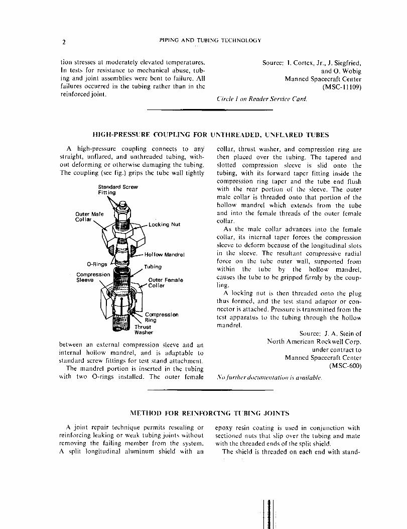
HIGH-PRESSURE COUPLING FOR UNTHREADED, UNFLARED TUBES
A high-pressure coupling connects to any
straight, unflared, and unthreaded tubing, with-
out deforming or otherwise damaging the tubing.
The coupling (see fig.) grips the tube wall tightly
Standard ScrewFitting
Ou'' 'e
Collar _ ! _Locking Nut
O-RinosZ :lCompression
Sleeve
between an external compression sleeve and an
internal hollow mandrel, and is adaptable to
standard screw fittings for test stand attachment.
The mandrel portion is inserted in the tubingwith two O-rings installed. The outer female
collar, thrust washer, and compression ring are
then placed over the tubing. The tapered and
slotted compression sleeve is slid onto the
tubing, with its forward taper fitting inside the
compression ring taper and the tube end flush
with the rear portion of the sleeve. The outer
male collar is threaded onto that portion of thehollow mandrel which extends from the tube
and into the female threads of the outer femalecollar.
As the male collar advances into the female
collar, its internal taper forces the compression
sleeve to deform because of the longitudinal slots
in the sleeve. The resultant compressive radial
force on the tube outer wall, supported from
within the tube by the hollow mandrel,
causes the tube to be gripped firmly by the coup-ling.
A locking nut is then threaded onto the plug
thus formed, and the test stand adapter or con-nector is attached. Pressure is transmitted from the
test apparatus to the tubing through the hollowmandrel.
Source: J.A. Stein of
North American Rockwell Corp.under contract to
Manned Spacecraft Center
(MSC-600)
No.further documentation is available.
METHOD FOR REINFORCING TUBING JOINTS
A joint repair technique permits resealing or
reinforcing leaking or weak tubing joints without
removing the failing member from the system.
A split longitudinal aluminum shield with an
epoxy resin coating is used in conjunction with
sectioned nuts that slip over the tubing and mate
with the threaded ends of the split shield.The shield is threaded on each end with stand-
t

FI.TTINGS, COUPLINGS, AND CONNECTORS 3
ard pipe threads and is designed with a small spaceadjacent to each side of the ferrule location to en-
sure a continuous circumfercntial epoxy seal. The
Space For Epoxy
Ferrule Shield /
\ \ / NutTu ing\ \ L_
aluminum shield is halved longitudinally with a
slit saw, and a generous coating of epoxy resin
is applied to the inner surfaces of each half.
Nuts to fit the pipe-threaded ends of the shield
are sectioned (see fig.) to just slip over the tub-
ing, the shield halves are clamped togetherover the joint, and the nuts are attached and
drawn up on the shield and threads. For in-
creased strength and clamping action, two such
nuts can be applied at each end of the shield.In this case, the nuts should be so sectioned that
their open portions lie on opposite sides of theshield.
Source: W. S. Lee and J. Kinzler
Manned Spacecraft Center
(MSC-I 1108)
Circle 2 on Reader Service Card.
SEI.F-SEAI.ING FITTING FOR INJECTION AND SAMPI.ING
OF I.IQUIDS
either introduced into or withdrawn from the
system without danger of contamination. This
technique greatly reduces the quantities required to
obtain representative system samples, and has been
successfully used for taking contamination control
samples from a fluid system located in an uncleanarea.
As shown in the sketch, a standard AN fitting
is modified by the introduction of two compres-sion wafers of silicone rubber with a durometer
hardness of approximately 40. Each washer is
punctured through its center by a very shortslit. The wafers are then installed in the fit-
ting so that the slits are at right angles to each
other to form a cross. A short piece of flared
thick-wall tubing is inserted into the fitting on
top of the compression wafers, and a standard
AN "13" nut is installed and tightened to com-
press the wafers. The blunt needle is then in-
serted through the wafer slits, without pe'r-
mitring any leakage or contamination.
A standard AN fitting has been modified to _[,t "-.J'_accept a blunt-ended hypodermic needle for inser-
tion into a liquid system so that material may be
HypodermicSyringe andBlunt Needle
AN Fitting _[ FlaredReworked to accept l/ Th ck-Wa I Tubina
Silic°ne Wafer_l_ N ,,B,, Nut
Weld_ [_ ____Silicone Rubber
Source: C. W. Overbey of
North American Rockwell Corp.under contract to
Manned Spacecraft Center
(MSC-15005)
,Vo./brtker docume_ltation L_a vai/oble.

4 PIPING AND TUBING TECtlNOLOGY
A QUICK DISCONNECT FOR CRYOGENIC FL[;ID IJNES
Poppet Valve
_// j__ _10peratingCam
Disconnect
J--V
A cam-operated valve can be used for handling
fluids at cryogenic temperatures and at very low
pressures. The valve (see fig.) is part of a quick-
disconnect coupling designed to implement the
separation of a space vehicle liquid fluid system
and its umbilicallycom_ected ground supplyfacility.
The cam-lever actuated poppet valve has been
used in conjunction with a ground half-disconnect
to overcome LOX tank ullage pressure decay
caused by "cryo-pumping" resulting from the
temperature differential across the LH2/LOX
tanks and He-pressurized common bulkhead. The
cam actuates the normally closed airborne half-
poppet to the open position when the ground half-
disconnect coupling is engaged, and maintains an
evacuated system while providing a thermal bar-
ier in the disengaged position.Source: E. J. Castaldo and P. J. Formolo of
North American Rockwell Corp.under contract to
Marshall Space Flight Center
(M FS-16622)
Circle 3 on Reader Service Card.
ELBOW FITTING WITH SELF-LOCKING COUPLING NUT
:r/2 _
r
_ Flared Tube
Type Fitting
_ Locking Ring
_._ " "B" Nut Coupling
A 7r,f2 rad (90 °) elbow fitting can swivel
27r rad (360 °) in one plane for more effective
alignment with mating hardware, yet may be
secured in place without the usual locking
devices. On existing elbow assemblies, the fitting
and Iocknut are secured by means of a locking wireinserted through a hole in the nut and a channel
in the fitting. When torqued beyond a certain
point, such an arrangement will shear the wire,
swage the fitting groove, or mutilate the channel,all of which are undesirable.
This improved technique (see fig.) uses a left-
hand threaded locking ring to ensure secure
attachment of the locknut to the fitting. Suf-ficient surface area is obtained on the face of the
locking ring to support the compression sur-

FITTINGS, COUPLINGS, AND CONNECTORS 5
face of the locknut, thus maintaining a 27r rad
(360 °) pressure on the sealing areas of the fitting.This eliminates the requirement for the lockingwire.
Source: F. L. Broadwick of
The Chrysler Corp.under contract to
Marshall Space Flight Center
(MFS-14366)
Circle 4 on Reader Service Card.
LIGHTWEIGHT HOSE ASSEMBLY WITH HIGH
FLEXIBILITY AND STRENGTH
Bel lows
(Flexible Section)
Collar Braid
Sleeve
Bel lows Neck
Tube End
A new hose design incorporates flexible sections
fastened to reinforcement braid. The assembly
is lightweight and flexible, is useful in high-
and low-pressure oxygen, helium, and hydrogen
systems, and can withstand pressures from689.5 kN/m 2 (100 psi) to 22,064 kN/m 2 (3200
psi) and temperatures from 294.25 K (70 ° F) to
58.15K( 423 °F).The all-metal hose assembly consists of a flex-
ible section, sleeves, reinforcementbraid, collars,
and tube ends (see fig.). The flexible section is an
annular, continuous convoluted bellows. An over-
lapping, double-row resistance weldment joinsthe end sleeves to the bellows neck, which fits
snugly within the inside diameter of the sleeve.The weldment is trimmed, still leaving a pres-
sure-tight joint, and the resulting end is sub-
sequently butt welded to the tube ends. Thestainless steel braid is then assembled over
the flexible section which is compressed in a
fixture to its required length. The braid is formedover the sleeve conical shoulder, and a collar
is positioned over and against the braid at the
sleeve cone area. This provides a clamping action
which is maintained by swaging and heliarc
welding the collar and the braid to the sleeve.Source: L. L. Bessing of
North American Rockwell Corp.under contract to
Marshall Space Flight Center
(MFS-1831)
Circle 5 oll Reader Service Card.

6 PIPING AND TUBING TECttNOLOGY
FUSIBI.E METAL USED IN HIGH-PRESSURE PIPE JOINT
A simple method increases the pressure hand-
ling capabilities of threaded pipe joints and
renders them practically impervious to thermal
PinchFit
Sea I
\
7
Bleed HoleFusible Metal in
Clearance SpaceBetween Threads
Female Fitting Male Fitting
transient conditions. Conventional flanged jointsusually fail in the extremes of these two areas.
in this application, the joint is assembled
dry to the proper seal compression and fusible
metal is flowed into the threaded area, filling
the void space between the threads. A bleed hole
is used as an exit for any gas trapped during
the filling process. The joint can be disassembled
by heating it while expelling the fusible metal by
applying pressurized gas to either end of the
threaded joint. For joints where one part cannotbe rotated relative to the other, or where a
precise angular relationship is required, a left-
hand/right-hand threaded turnbuckle-type doublejoint can be used.
Source: R. E. Meyer of
Pratt & Whitney Aircraftunder contract to
Marshall Space Flight Center
(MFS-21176)
No fitrther documenlathm is available.
Section 2. Flexible Devices and Vibration Damping
PI.ASTIC TUBING PROTECTS FLEXIBLE COPPER HOSE
Connection to Shrinkable Plastic
Water Supply Sleeving
Reinforcing flexible copper pt, rge and coolant
hoses with a sleeve of high-temperature shrinkable
plastic has proven to be an excellent protectivemeasure in a severe vibration condition, such as
testing a rocket engine. Similar flexible copper
coolant lines can be used in automotive ap-plications.
The flexible copper hose is inserted into a
slightly larger plastic tube. Sufficient heat is
then applied to shrink the plastic until it assumesthe contour of the hose in intimate contact.
Flexible Copper
_ Conn ector
During operation, the plastic covering permits the
copper hose to take a radial bend without kink-
ing, and prevents it from taking a permanent
bend (setting). The plastic covering also serves
as a reinforcement of the joint between thehose and fitting.
Source: B. E. Mellgrcn of
North American Rockwell Corp.under contract to
Marshall Space Flight Center(MFS-772)
No /itrther docmneHtation it availahh,.

FLEXIBLE DEVICES AND VIBRATION DAMPING 7
SPHERICAL PIPE JOINT LOADS MATING FI.ANGES EVENLY
A large-diameter ball joint pipe fitting trans-mits an evenly distributed load to the mating
flanges of a large duct. The fitting incorporates
Reverse Load Device Outer Bearing Race
Mating Bellows _ _ _fSI: 'ing_1 Bearing
Flange _ _ Inner
__.[ _..r'_-__/__ r Bearing
.... , Race
two spherical bearing races and balls in contact
with centering cage springs that enable the races
to center themselves when the joint is angu[ated.
An inner bearing race is slotted to providea channel in which a reverse load device with
spherical, tipped fingers may move inward while
under reverse loads and while traveling through
the angular movement of the ball joint. Curved
springs center the ball bearing, preventing it
from free floating while the ball joint is under
the reverse loading. The bearing contains 1,728
balls for high thrust loads through a ±rr/18 rad
( i 10°) oscillation at 10 cpm.
This design should find application in piping
systems where unequal load distributions exist.
Source: R.O. Pfleger of
North American Rockwell Corp.under contract to
Marshall Space Flight Center
(M FS-807)
Circle 6 on Reader Service Card.
TFE-FLUOROCARBON LINERS FOR FI.EXIBLE HOSES
,__. ___.___._ ,_--_, $_e_IFE eCnYt/indriCal Parallel Offset
A flexible hose handles high flow rates under
high pressure while permitting greater parallel
offset than 0.I0. Conventional hoses, commonlyreinforced with one-piece or two-piece liners, allow
the flow to impinge on the surrounding metal-
lic bellows, causing failure of the hose.
To prevent this type of failure, a superior
flexible liner is made from short lengths of TFE-
fluorocarbon tubing. The outside diameter of one
end of each length is reduced so that it becomes
a male end; the internal diameter of the other
end is increased, making it female. The joints

8 PIPINGANDTUBINGTECtlNOI.OGY
betweenthelengthsarethusslidingoverlapsthat
permit flexibility with much greater parallel off-
set. The liners are surrounded by the usualmetallic bellows covered with braid.
Oil companies and hose manufacturers may beinterested in this new technique.
Source: D. F. Higley of
North American Rockwell Corp.under contract to
Marshall Space Flight Center
(MFS- 16480)
Circh, 7 on Reader Service Card.
FLO%V LINER EXTENDS OPERATING LIFE
OF ttlGH-ANGULATION BELLO%VS
Fill _-"X7 _-'ateher
_1_- _ Section
Unlined Bellows
A flow liner appreciably extends the service
life of externally gimballed high-angulation _/6.92
rad (26 degree) bellows at duct points handlinghigh-velocity fluid flow in a liquid oxygen trans-
port system. Unlined bellows have failed due
to flo_-induced vibration; and conventional,
full-length conical liners, while protecting the
interior of the bellows, result in an unacceptableredtiction in flow area.
The solution (see fig.) is a bellows liner con-
sisting of t_vo sections: (I) a conical frustum
or nozzle on the upstream side; and (2) acylindrical .,,cotton or catcher on the down-
Lined Bellows
stream side. The liner directs a jet from the nozzle
across the open gap to the catcher on the other
side of the bellows. The vibration-inducing flow
is thus directed away from the bellows con-
volutions, while full gimbal motion and arelatively small reduction in flow area are allowed.
Source: D.G. Rumph of
The Boeing Companyunder contract to
Marshall Space Flight Center
(MFS-12023)
Circle ,_on Reader Service Card.
BEI.LOWS JOINT ABSORBS TORSIONAL DEFLECTIONS
IN DUCT SYSTEM
A long, thin-walled bellows, compressed into a
much shorter length absorbs torsional deflections
in duct systems wherc the usual dogleg, dual
bellows arrangement, cannot accommodate
a short, straight run. In the dogleg configuration,torsional loading in either half is absorbed
by angular dcflection of the bellows in the op-
posite half. Short space, and a requirement for
I
FLEXIBLE DEVICES AND VIBRATION DAMPING 9
Flange
Thin WalledBellows
a straight-in approach, preclude the use of
the dogleg approach.
A long, thin-walled bellows is compressed into
a short length and then installed in a flanged
linkage, which takes the separating pressure loadand restricts the motion that the bellows absorbs
due to torsional deflections. The bolts holding the
two flanges of the torsional bellows are loosely
torqued to take the separating pressure loadand to allow relative torsional deflection be-
tween the two.
The torsional bellows has a lower torsional
spring rate than any of the other bellows in theduct assembly, it thus absorbs the bulk of the
duct's torsional deflections, leaving the other
bellows of the duct assembly free to absorb
the axial and angular deflections.Source: C. M. Daniels of
North American Rockwell Corp.under contract to
Marshall Space Flight Center
(MFS-882)
Circle 9 oH Reader Service Card.
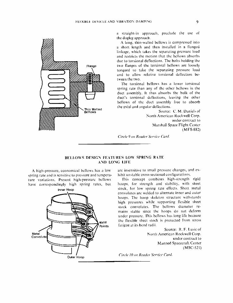
BELLOV¢S DESIGN FEATURES LOVe SPRING RATE
AND LONG LIFE
A high-pressure, economical bellows has a low
spring rate and is sensitive to pressure and tempera-ture variations. Present high-pressure bellows
have correspondingly high spring rates, but
Inner Hoop
_ WeId
Points
Outer Hoop
are insensitive to small pressure changes, and ex-
hibit unstable cross-sectional configurations.
This concept combines high-strength rigid
hoops, for strength and stability, with sheet
stock, for low spring rate effects. Sheet metalconvolutes are welded to alternate inner and outer
hoops. The hoop skeleton structure withstands
high pressures while supporting flexible sheetstock convolutes. The bellows diameter re-
mains stable since the hoops do not deform
under pressure. This bellows has long life because
the flexible sheet stock is protected from stress
fatigue at its bend radii.Source: R. F. Lusic of
North American Rockwell Corp.under contract to
Manned Spacecraft Center
(MSC-521)
Circh" 10 oH Reader Service Card.
10 PIPING AND TUBING TECHNOLOGY
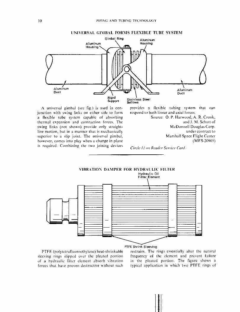
UNIVERSAl. GIMBAL FORMS FLEXIBLE TUBE SYSTEM
G imbal Ring Aluminum
Aluminum _ Housing
Housing _ f
a,uminum _ _ a,_minum
Duct \ "_ Duct
RigidSupport Stainless Steel
Bellows
A universal gimbal (sec fig.) is used in con- provides a flexible tubing system that can
junction with swing links on either side to form respond to both linear and axial forces.a flexible tube system capable of absorbing Source: O. P. Harwood, A. R. Cronk,
thermal expansion and contraction forces. The and J. M. Schuttof
swing links (not shown) provide only straight- McDonnell Douglas Corp.line motion, but in a manner that is mechanically under contract to
superior to a slip joint. The universal gimbal, Marshall Space Flight Center
however, comes into play when a change in plane (MFS-20965)
is required. Combining the two joining devices Circle I 1 on Reader Service Canf.
VIBRATION DAMPER FOR HYDRAULIC FILTER
Hydraulic OilFilter Element
PTFE (polytetrafluoroethylene) heat-shrinkable
sleeving rings slipped over the pleated portion
of a hydraulic filter element absorb vibration
forces that have proven destructive without such
PTFE Shrink Sleeving
restraint. The rings essentially alter the natural
frequency of the element and prevent failurein the pleated portion. The figure shows a
typical application in which two PTFE rings of
1

FLEXIBLE DEVICES AND VIBRATION DAMPING 11
the shrink sleeving have been applied over
the filter pleats. In practice, the required num-
ber of PTFE rings are slipped over the filter
pleats and heat is applied to shrink the rings intointimate contact with the pleated section.
Source: R. E. Prout of
North American Rockwell Corp.under contract to
Marshall Space Flight Center
(MFS-16173)
,\'o./itrther documentation is available.
J
A threaded union-type gimbal functions without
the use of bolted flanges and seals. Its simplicity
permits easy replacement, and line assembly can
be accomplished at less cost since the tubing
can be fabricated to wire templates developed
by normal mockup procedures. The innovation
presents a good method for reworking existingline assemblies.
THREADED UNION-TYPE GI.MBAI.
,_./Gimbal
i_._t _ v S 1
Source: M. C. Eycstone ofNorth American Rockwell Corp.
under contract to
Marshall Space Flight Corp.
(MFS-13870)
No further documentation is available.
HIGH FLOW, HIGH PRESSURE GIMBAI. JOINT
h _ I
pT s II
Pad _Bolt

12 PIPING AND TUBING TECIINOI.OGY
A lightweight, high flow, high pressure gimbal
joint gives leak-tight angulation through 7r/30
rad (6 degrees) about its centerline when operat-
ing at 41,364 kN/m2 (6,000 psi). By using several
such joints in fluid transfer systems, compensa-tion can be achieved for relative motion between
stationary and transporting storage devices. The
joint is smaller and lighter, and can withstand
higher pressures than the bellows type described in
the preceding item. The design can be appreciably
upgraded by proper material selection to handlc
operating pressures as high as 103,410 kN/m 2
(l 5,000 psi) at elevated temperatures.Source: J. S. Kunkle
Kennedy Space Center(KSC-10205)
Circle 12 on Reader Service Card.
Section 3. Devices Used for Regulation and Control
IMPROVED DRAG-TYPE
A flowmeter for low-range, high-response meas-
urements will reduce unsymmetrical flow to a
negligible level. Previous designs permitted
Drag Body
unsymmetrical flow around the drag body
and resulted in reduced output and/or poor re-
sponse characteristics.
FLOWMETER: A CONCEPT
The new design introduces two abutting sleeves
in the flow passage. These sleeves, one of which
is notched to clear the cantilever support, are
inserted axially into the flow passage after the
drag body has been installed radially through
a clearance bole. The sleeves act as over-range
deflection stops that may be changed, without dis-
turbing the drag body, by substituting sleeves
having different bores.Source: L. H. Groeper of
North American Rockwell Corp.under contract to
Manned Spacecraft Center
(MSC-15908)
No further documentation is a vailabh'.
FLOW RATE RANGE CONTROLLED BY CAVITATING VENTURI
Venturi
Installing a cavitating venturi in the flowline
between supply tanks and fluid injectors eliminates
appreciable testing by making test hardware
pressure drop independent of supply' tank pres-
Flow
sure. By installing the cavitating venturi, flow
rates become a function only of upstream
temperature and pressure, and any preselectedflow rate can be achieved by providing a tank
I

DEVICES USED FOR REGULATION AND CONTROL 13
pressure read from the venturi calibration curve,
using the desired flow rate and temperature.
Using this method, flow rates have been deter-mined'from venturi upstream pressure and tem-
perature with the precision of 0.5% flowmeters.
Source: J. L. Kitchens and R. L. Ingrain of
North American Rockwell Corp.under contract to
Manned Spacecraft Center
(MSC-91102)
Circle 13 on Reader Service Card.
ORIFICE FOR AUTOMATICALLY REGULATING FLO_' RATE:
A CONCEPT
A variable-area, self-actuating orifice could
control flow rate to maintain a preselected pres-
sure drop at its output. The conceptual design
Booster SpringIf Required
Bellows..._.,,_ _, ..
Plug (Body or Revolution -- _-_Shape Can Be Varied toGive Required Orifice Change)
consists mainly of a bellows supporting a
fixed-area annular piston. The port in the piston
is centered on a plug with a contour matched
to the spring rate of the bellows. This provides
the proper area variation, under flow conditions,
to maintain the required back pressure.
In operation, the bellows senses the pres-
sure differential across the orifice, and responds
to any change in this differential by changing in
length, so that the orifice area is correspondingly
changed to maintain a constant pressure drop.Source: S. D. Butler and E. F. Shacffer of
North American Rockwell Corp.under contract to
Marshall Space Flight Center(MFS-13915)
No further documentation is available.
PRESSURE BI.OCK AND VENT WITH INTEGRAl. RELIEF VALVE: A CONCEPT
This concept would automatically shut off
system pressure to a given gage using an arrange-
mcnt of increasing pressure stages, each monitored
by its own gage. The device limits the maximum
Damping Orifice _Gage or Transducer Port
Inlet VentPort _I___ _ f_ _ _ Port
Relief Port _"-'_ Adjustable/Replaceable/_ Spring
Integral Relief Valve
pressure to which each gage is subjected, andthen vents the next lower range gage. This
facilitates reading the next gage in line when
the next higher pressure stage is attained. The
device is essentially a spring-loaded spool valve
with a spring tension calibrated to yicld to the
prcselected pressurc. A relief valve integral
to the device protects against possible line surges.Source: R. L. Gochowski of
North American Rockwcll Corp.under contract to
Marshall Space Flight Center
(M FS- 16970)
No further documentation is available.

14 PIPING AND TUBING TECHNOLOGY
AUTOMATIC HUMIDITY REGULATION IN DECONTAMINATIONSYSTEM
ChamberPressure
Gage FilamentHumidity Sensor \ K'_ . heated
_k_ f,--] Preheating Oven SteamI_ " I , (Heat Exchanger) ......... I Aspirator
A t' I©/ xk- Sterilization 1 =
Clamber ___£ ,_ '_ Z--_ll -- _J_ -'Dy, Filtered_ txlE_=__. Z--_----------__ _+__. 1 tAir Sourc__e _.f--I I " Humidity Controller[- qii |_ _.-__ [ l Heat Exchanger _-_ JlJ I I_ryAir 7 IIr-= --=-__ li , HeaterSo,enoidi-, Ill _ _ ' _; IFi,amentsValve _ _ (7 I1, L- .....
( _ \ I' /I I _ liii _ ExhaustH \ I / _-- 4- - - _ - SolenoidI 1 \ .... /-- - - _- - - --L___L_L ValveI I _Tn_=.... ;:Tn _ Master Programmer-] I "_h_'o_i;n;' Solenoid _ T,mer (CamType)
L___J Valve Valve _ ----- ElectricalETO-Freon Integral Vacuum- -- Gas FlewSource Pressure Pump
Incorporation of an aspirator and flash evapora-
tion chamber in a specially designed and con-
structed automatic ethylene oxide/freon gasdecontamination system has improved humidity
regulation over the long term (300 to 500 hours)
decontamination cycles involved. The new sys-
tem minimizes contact between sterilant gas and
steam or water and the heater elements, thus in-
hibiting long term decomposition of the decon-
taminating gases.
The flowing stream of gas passes continuously
through the aspirator, but not in direct contact
with the water or heaters. Passage of the gas
PressureRegulator
Dry, FilteredAir Source
Sv ?v °'d
-- _ Water Reservoir
creates a vacuum that pulls water vapor from
the steam generator and into the gas stream, on
an as-generated basis. A humidity-controlledsolenoid valve meters water from the reservoir
into the steam generator to achieve long termhumidity control within the sterilization chamber.
Source: R. H. Silver and S. H. Kalfayan of
Caltech/JPLunder contract to
NASA Pasadena Office
(NPO-10540)
Circle I4 on Reader Service Card.
ELECTRICALLY ACTUATED BURST DISK ASSEMBIA"
A composite burst disk, which gives way to
pressure when an electric current is applied,
should prove useful wherever programmed ventingis desired.
The assembly consists of a plastic disk backed
by a frangiblc mctal disk which is placed on the
high-pressure side of the unit. The two disks are
held together and to the pressure pipe with a
flange mounting. A resistance wire, mounted
on the plastic disk around the inner perimeter of
the flange, is connected to a voltage source.Composite burst disks of brass shim stock
and acetate (mylar) were used to vent a solid
propellant motor with a 5.08 cm diameter vent.
Mylar disks 0.036 cm thick were used with brass
disks from 0.005 to 0.018 cm thick to provide

DEVICES USED FOR REGULATION AND CONTROl_ 15
an
kN/m 2 (100 to 1200 psi). The 0.036 cm thick
mylar disks permitted pressures of 1722 to
2067 kN/m 2 (250 to 300 psi) above the burst
pressure of the brass disks.
Nichrome resistance wire of 0.02 f_/cm was
Meta I,Disk
Pressure Leads
Vent
/I
operating pressure range of 689 to 8268 The metal and plastic disks can be fabricated
inexpensively from sheet material, eliminating theneed for costly close-tolerance burst disks or
explosive bolt systems. The composite disk
assembly does not require a momentary over-
pressure to achieve venting.
fastened to the surface of the mylar disks with
ordinary masking tape. When the resistance wire
was heated with a 24 V supply, the assemblywas caused to fail and the motor vented within
20 to 100 msec, depending upon the motor
Source: G. E. Jensen of
United Aircraft Corp.under contract to
Langley Research Center
(LAR-10479)
pressure and the thickness of the brass disk.No further ¢tocume, tatio, L_available.
SIMPLIFIED RUPTURE DIAPHRAGM FOR STANDARD FITTINGS: A CONCEPT
A pressure relief device in the conceptual
stage is designed to operate in standard flared-
tube fittings without the need for any system or
component modification. The diaphragm, made
of oxygen-free high conductivity (OFHC)
copper, corresponds basically to the commer-
cially available, conical metallic seal used for such
fittings, with the exception that no hole is in-cluded. Material thickness is controlled, and the
conical shape ensures correct positioning of thecoined side for consistent burst value.
Source: E. M. Saxelby ofNorth American Rockwell Corp.
under contract to
Marshall Space Flight Center
(MFS-13662)
No further docm,e,tatio, is available.

16 PIPING AND TUBING TECtINOI.OGY
Section 4. Shop Hints for Maintenance and Repair
TEI.ESCOPING OF INSTRUMENTATION TUBINGELIMINATES SWAGING
A rapid, economical method for fabricatingsmall-diameter tubing for instrumentation ap-
plications has been devised. Such tubing is con-
ventionally fabricated by a swaging operation,
which requires the use of relatively costly dies and
frequently results in excessive material loss be-cause of fractures produced when attemptingmaintenance of close tolerances.
Short sections of commercially available
stainless steel tubing of slide-fit sizes are fitted
together and silver-soldered at the junctions. The
large-diameter tubing section is connected
to a standard plumbing fitting, and the stepped-
down sections are successively fitted in placeuntil the desired reduction in diameter is obtained.
The tubing sections are secured together by silver
soldering. Tubing fabricated by this method has
been quickly and easily connected between
0.038 cm (0.015 inch) diameter pressure tapsat various locations on wind-tunnel models and
standard 0.318 cm (0.125 inch) diameter instru-
mentation plumbing.
SoIder
Source: E. L. McClellan of
North American Rockwell Corp.under contract to
Marshall Space Flight Center
(MFS-546)
Circle 15 on Rea_h'r Service Card.
PIPE CUTTING TOOL FOR USE IN IJMITED SPACE
LociVeShaft
king Pin
Fulcrum
,o0Cutting Pressure _ "_ \ _ .,_ ./'_.
Lock RotatableArm
A means has been found for cutting pipe or
tubing in areas restricted by adjacent structuralmembers. A portable tool clamps the pipe firmly
and then rotates a cutter assembly that is in-
ternally connected to a drive shaft engaged inthe chuck of an electric drill.
The rotatable arm is opened to allow in-
sertion of the pipe. The pipe is clamped in place
by closing the rotatable arm, tightening the cutterassembly lock knob, and inserting the locking
pin. The blade cutting pressure is then adjusted,
and a portable electric 'drill is connected to thecutter drive shaft.
As the cutting progresses, it may be necessary
to periodically tighten the cutting pressure ad-
justment knob until the pipe is severed. When
1

SHOP HINTS FOR MAINTENANCE AND RIPAIR 17
cutting is completed, the clamping membersare opened and the blades are backed off to
prevent accidental overloading of the cutter
assembly at the start of the next cutting opera-tion.
Title to this invention, covered by U.S. Patent
No. 3,136,057, has been waived under the pro-
visions of the National Aeronautics and Space
Act (42 U.S.C. 2457 (f)) to the McDonnell
Aircraft Corporation, Box 516, St. Louis,Missouri, 63166.
Source: D. D. Jones and C. A. Headley of
McDonnell Aircraft Corp.under contract to
Manned Spacecraft Center
(MSC-36)
IMPROVED TOOL EASII.Y REMOVES BRAZED TUBE CONNECTORS
A portable, compact tool for removing brazedtube connections eliminates undesirable oxidation
on the tube surfaces and lends itself to use in
cramped areas. Conventional tools have short
service lives because they use the heating
unit to exert the necessary separating force.
Power
Leads
C lamp ._ T_
Heating _ J _
Device• I2CTube _ ,_'_ ,d--I/_-_'_",,,.J,_ Gas
7/ t _ _ • Opening
Pivot Handle
Barrel Nut
The new tool uses an induction coil to melt the
braze and a compression spring to automaticallyseparate the connection. An inert gas such asargon is force-fed about the heated area to
prevent tube oxidation.
First, the connection is cut, preferably with atool that will crimp its walls inwardly to form a
rough ridge or burr. The pulling device is then in-serted into the connector until the cone head on
the sleeve is past the burr. The barrel nut is ro-
tated counterclockwise as the sleeve is held,
causing the cone head to expand outwardly
and grip the connector ridge from within. Thepressure plate is forced over the sleeve and
pressed against the barrel nut, thus compressing
the spring, and the heating device is placed over
the connector and clamped shut. High-frequency
current is applied to the induction coil in the
heating device through the leads in the end of
the handle, and argon gas is applied to the
induction coil area through the gas port in the
PressureInduction Cone Plate
Coil Head /
_,_-_ _._ .... Sleeve
/ .....Tobe
V///'_////////_ S wing NUt re I
Heating UnionDevice
Heating Device Details
handle. As the braze melts, the force of the
compression spring backs the connector off of
the tube. Current is removed, and the argon
gas is allowed to flow until the danger of oxida-tion is past.
Title to this invention has been waived under
the provisions of the National Aeronautics and
Space Act (42 U.S.C. 2457 (f)) to McDonnell
Aircraft Corporation, Box 516, St. Louis,Missouri, 63166.
Source: R.A. Schoppman of
McDonnell Aircraft Corp.under contract to
Manned Spacecraft Center
(MSC-263)

[8 PIPINGANDTUBING TECtINOLOGY
ORBITAl. TUBE FLARING SYSTEM PRODUCES CONNECTORS
%VITH ZERO LEAKAGE
An orbital tubc flaring system, which is a modi-fied version of the split die and cone, incor-
porates a rolling cone and rolling die to closelycontrol flare formation, achieving zero leakage in
high-pressure systems.End View Rolling Die
• Tube _ - /'_---_'k
Rolh g Co Tube Centerlme
Start
Rolling Die Tube ClampSide View _ /
_ri_S,_ _
The zero-leakage can be obtained from welded
and brazed joints or from precision mechanical
connectors which mat' be assembled arid dis-
assembled. Ahhough there are many tube flaring
methods, including impact forming, ballistic form-
ing, hydraulic forming, pneumatic forming, and
the conventional split die and cone procedure,
it is extremely difficult to produce a flared tube
configuration with zero leakage.
The orbital system produces a flare on the tube
end by rolling the material between an ex-
ternally orbiting rolling dic and an eccentrically
rolling internal cone. The rolling dic is thc essen-
tial difference between the oribtal flaring method
and thc con'_entional flaring ststem which uses
a split die as the flare receptacle. The rolling
die and the rolling cone are held in rotational
registrt' at all times, permitting the tube material
being flared to be formed between the two
rolling surfaces.
The three primary parts of the system are: the
tubc clamp, the I.D. flaring cone, and the O.D.
rolling die. The tube ckunp is designed to hold theO.O. of thc tube concentric _ith the centerline
of rotation of the main spindle which drives the
orbital adaptor flaring head. The tube holder
design incorporates an iris type collet which
compensates for slight variations of the tube
diameter; the O.D. of the tube is therefore
always positioned concentrically. The split
jaw die holder on the commercial machine is
replaced by a one-piece bracket which con-
centrically positions the iris type tube collet.The I.D. flaring cone of the orbital st'stem
functions in a manner similar to the I.D. flar-
ing cone on the conventional flaring machine.The cone is completely bearing mounted and isfree to roll about its own centerline. The
centerline of the cone shaft is slightly ec-centric to the centerline or rotation of the main
drive spindle. Therefore, during operation, thecenterline of the cone orbits around the center-
line of the main drive spindle. The flaring action
takes place as the O.D. surface of the flare cone
is forced axially against and rolls around the
I.D. of the tube. The cone is driven only by
frictional contact as the material being flared
bottoms against the rolling die.Source: J. R. Williams
Marshall Space Flight Center
(MFS-2016)
Circle 16 on Reader Service Card.
I

SHOP HINTS FOR MAINTENANCE AND REPAIR 19
CLEANING METHOD FOR BEI.LOWS CONVOLUTIONS: A CONCEPT
Bellows Convol ut ionCleaning Fluid
Travel
,<
• ,';.., ; , ,
Spray Pattern
Hand-Held CleaningFluid Dra Fluid Spray Nozzle
A proposed method for cleaning the convolu-
tions of a bellows removes foreign materials
such as dust and other matter that could damage
high speed pump impellers. This previously
presented a real problem due to the small access
area and relatively large entrapment volume.
A small metal tube, attached to a system for
pumping the cleaning fluid, has two thin slots
machined in its cleaning end at opposite sides
(rr rad (180 °) apart). Starting at the uppermost
convolution, the two opposite jets enter the
cavity and are progressively moved down,
flushing each succeeding convolution and permit-
ting the spent fluid to drain freely through the bel-lows outlet.
Source: J. M. Lynn of
North American Rockwell Corp.under contract to
Marshall Space Flight Center(MFS-13935)
No ]_lrther doc,mentatio, is a railable.
GUIDES PROTECT BEI,I,OIVS DURING PRESSURE TESTING
A protective device, consisting of internal
guides, assists in pressure testing bcllows used
in fluid flow systems. Two end caps (sec fig.)with O-ring seals are arranged to close the end
flanges of the bellows under test. One end caphas a blind thread and the other has a through /
f
thread, so that they may be assembled and ad- ,>.jjusted lengthwise on a threaded through rod. The /threads are of sufficient length to adjust the bel-
lows from fully restricted 1o full.}' e,_lended. The
through-threaded end cap contains the inlet (-..port, through which pressurized air is introduced ).into the test bellows via a blind center hole t
and intersecting radial hole in the threaded rod. )-.
Prior to attachment of the end caps, rings of
cork or a suitable elastomer are arranged on
the center rod in a manner which wil! support
the inside of the bellows convolutions. These rings
I
AInlet Port /
, EndCap
O-Ring\
Threaded Rod
Port
Spacer
Bellows
=.I(3
o

20 PIPING AND TUBING TECIINOLOGY
have no effect on the burst pressure of the bel-
lows, but the)prevent the bellows from buckling
and whipping when internal air pressure is
applied.
Source: B.T. Howhmd of
North American Rockwell Corp.under contract to
Manned Spacecraft Center
(MSC-15264)
Ao /ilrther documentation is availahle.
IMPROVED TECHNIQUE FOR COUPI.ING FI.EXIBLE T1BINGONTO RIGID TI!BING
iFlexTubing Ferrule
't fl Externally
RigidTubing ThreadedDie
A simple, improved technique uses a ferrule and
a hand tool with internal and external dies toco@le flexible tubing onto rigid metal tubing.
The flexible tube end is slipped over the metal
tube end, the ferrule is slipped over this junction,and the tool _ith dies installed is rotated around
the ferrule, crimping it firmly in place. This
i
roll-crimped ferrule exerts appreciable, constant,
and equal pressure around the joint.Source: J. C. McConnell
Wallops Station
(WLP-10006)
NoJ}wther documentatioH is available.
ADJUSTABI.E SADDLE
An adjustable saddle clamp has the flexibilityand range to clamp a tube or hose _hose
Loo_.
_i -i_)/_iffener:
IillIJj! Jill
CI.AMP FOR TUBING
outside dianlcter may vary as much as 0.635 cm
(0.25 in.) during system operation. This is an
appreciable improvement over conventional
lixcd-dimension clamps that can only be usedfor items that are manufactured to and retain
close Lolerances. The clamp should be useful in
the automotive industry and in the installation
of insulated tubing for thc plumbing, heating, andair conditioning industries.
Source: J. Ftihan of
North American Rockwell Corp.under contract to
Marshall Space Flight Center
(MFS-14031)
Circle 17 on Reader Service Card.

SHOP HINTS FOR MAINTENANCE AND REPAIR 21
ADAPTER SIMPLIFIES FL[TSH CI,E_NING OF FEMAI.E HAI.F COUPI,ERS
An inexpensive adapter made from a standard
reducer provides a cheaper and more efficient
means of flush cleaning fluid syMem couplers.
Flared Tube
.,_ / _--_--___ _Reducer
///__/ ,__ M_[ edified Bore
[__l__/%,__i_fi _ ed Slot
Previously, the more expensive test point connector
was used as the flush cleaning connector.
in some fluid systems, the female half couplers
arc repeatedly used to engage the male stems of
the system. In one fluid system, for instance, 73
male stems arc used at test points, and up to
150 connections arc made to each during weld
purging, flushing, testing, etc. With the simplified
flushing adapter (sec fig.), considerable savings arc
realized compared to the use of clas.,, l stems,
which cost several hundred dollars each.
Source: J. A. Klein and H. tt. Maltby of
North American Rockwell Corp.
under contract to
Manned Spacecraft Center
(,M SC- 17096)
CircA" 18 on Reader Serricc CYmL
CI,EANER FOR CONVOI.[TTED HOSE
A new cleaner does an excellent job of clean-
ing convoluted flexible hoses, and has a built-in
method for determining the degree of cleanliness
achieved. Previous methods have proven un-
satisfactory because the cleaning was done with
thc hose lying in a horizontal plane, either coiled
or extended. With the hose horizontal, dirt tended
to remain in the bottom of the convolutions, even
though cleaning solvent was forced through
vigorously.
In the method devised, the convoluted hose
is suspended from a winch, and the lower end of
the hose is attached to a fixture adapter. A hosc
of PTFE (polytctrafluoroethylcnc) is inserted
into the full length of the convoluted hose and
is topped by a spray nozzle. The lower end
of the PTFE hose is attached to a reel hollow
shaft which is connected to a cleaning fluid
source. As cleaning fluid is forced through the
PTFE hose to its spray nozzle, the reel is turned
to slo_ly lox_er the spray nozzle. This action
cleans the convolutions one-by-one, and allows
the cleaning soh'cnt and dislodged dirt to bc
carried off by gravity. An affluent port provides
a means of sampling the descending fluid to
determine the degree of cleanliness being
achieved in the flexible hosc convolutions. Several
cleaning passes can bc easily accomplished as
necessary to obtain the desired cleanliness.
Wineh_
Winch Adapter Spray Nozzle
PTFE Hose r_lJ'-_._._a_Convoluted
Fixture Adapterand Affluent _
Sampling Port
.¢0 E_ w
FlexibleHose to beCleaned
Swivel SmoothJoint Lined
_-4_"_ Flexible
T7 "°se
Source: T. L. Moen of
McDonnell Douglas Corp.
under contract It)
Marshall Space Flight Center
(M FS-20590)
Circle I 9 oil Rea&'r Service Card.
NASA-Langley, 1971

t


