433
| Date post: | 14-Sep-2014 |
| Category: |
Business |
| View: | 8,210 times |
| Download: | 542 times |


Piping Systems Manual

About the AuthorBrian Silowash, PE, CEM, LEED AP, is president of Innovative Design Engineering of America, LLC, a Pittsburgh-based engineering consulting firm special-izing in facilities engineering, energy management, in-surance consulting, and building inspections. He has worked as a maintenance foreman, a plant engineer, and an engineering consultant. Mr. Silowash has ex-tensive experience in design, construction, and com-missioning.
Piping Systems Manual
Brian Silowash
New York Chicago San Francisco Lisbon London Madrid Mexico City
Milan New Delhi San Juan Seoul Singapore Sydney Toronto

Copyright © 2010 by The McGraw-Hill Companies, Inc. All rights reserved. Except as permitted under the United StatesCopyright Act of 1976, no part of this publication may be reproduced or distributed in any form or by any means, or stored ina database or retrieval system, without the prior written permission of the publisher.
ISBN: 978-0-07-159277-2
MHID: 0-07-159277-6
The material in this eBook also appears in the print version of this title: ISBN: 978-0-07-159276-5, MHID: 0-07-159276-8.
All trademarks are trademarks of their respective owners. Rather than put a trademark symbol after every occurrence of a trademarked name, we use names in an editorial fashion only, and to the benefit of the trademark owner, with no intention ofinfringement of the trademark. Where such designations appear in this book, they have been printed with initial caps.
McGraw-Hill eBooks are available at special quantity discounts to use as premiums and sales promotions, or for use in corporate training programs. To contact a representative please e-mail us at [email protected].
Information contained in this work has been obtained by The McGraw-Hill Companies, Inc. (“McGraw-Hill”) from sourcesbelieved to be reliable. However, neither McGraw-Hill nor its authors guarantee the accuracy or completeness of any information published herein, and neither McGraw-Hill nor its authors shall be responsible for any errors, omissions, or damages arising out of use of this information. This work is published with the understanding that McGraw-Hill and its authorsare supplying information but are not attempting to render engineering or other professional services. If such services arerequired, the assistance of an appropriate professional should be sought.
TERMS OF USE
This is a copyrighted work and The McGraw-Hill Companies, Inc. (“McGraw-Hill”) and its licensors reserve all rights in andto the work. Use of this work is subject to these terms. Except as permitted under the Copyright Act of 1976 and the right tostore and retrieve one copy of the work, you may not decompile, disassemble, reverse engineer, reproduce, modify, create derivative works based upon, transmit, distribute, disseminate, sell, publish or sublicense the work or any part of it without McGraw-Hill’s prior consent. You may use the work for your own noncommercial and personal use; any other use of the workis strictly prohibited. Your right to use the work may be terminated if you fail to comply with these terms.
THE WORK IS PROVIDED “AS IS.” McGRAW-HILL AND ITS LICENSORS MAKE NO GUARANTEES OR WAR-RANTIES AS TO THE ACCURACY, ADEQUACY OR COMPLETENESS OF OR RESULTS TO BE OBTAINED FROMUSING THE WORK, INCLUDING ANY INFORMATION THAT CAN BE ACCESSED THROUGH THE WORK VIAHYPERLINK OR OTHERWISE, AND EXPRESSLY DISCLAIM ANY WARRANTY, EXPRESS OR IMPLIED, INCLUD-ING BUT NOT LIMITED TO IMPLIED WARRANTIES OF MERCHANTABILITY OR FITNESS FOR A PARTICULARPURPOSE. McGraw-Hill and its licensors do not warrant or guarantee that the functions contained in the work will meet yourrequirements or that its operation will be uninterrupted or error free. Neither McGraw-Hill nor its licensors shall be liable toyou or anyone else for any inaccuracy, error or omission, regardless of cause, in the work or for any damages resulting therefrom. McGraw-Hill has no responsibility for the content of any information accessed through the work. Under no circum-stances shall McGraw-Hill and/or its licensors be liable for any indirect, incidental, special, punitive, consequential or similardamages that result from the use of or inability to use the work, even if any of them has been advised of the possibility of suchdamages. This limitation of liability shall apply to any claim or cause whatsoever whether such claim or cause arises in contract, tort or otherwise.

In memory of my parents, George and Juliana Silowash
“Deep waters cannot quench love, nor floods sweep it away.”—Song of Songs 8:7

This page intentionally left blank
vii
ContentsAcknowledgments . . . . . . . . . . . . . . . . . . . . . . . . . . . . xvi
Chapter 1 Introduction 1Some Miscellaneous Thoughts on Piping . . . . . . . . . 2
Chapter 2 Terminology 3
Chapter 3 Reference Materials 15
Chapter 4 Piping Codes 17ASME B31.1 Power Piping . . . . . . . . . . . . . . . . . . . . . 21
100.1.2 Scope . . . . . . . . . . . . . . . . . . . . . . . . . . . . . 22100.1.3 Not in Scope . . . . . . . . . . . . . . . . . . . . . . . 22102.3.2 Limits for Sustained and
Displacement Stresses . . . . . . . . . . . . . . . . . . . 22104.1 Pressure Design of Straight Pipe . . . . . . . 22104.3 Branch Connections . . . . . . . . . . . . . . . . . . 25104.3.3 Miters . . . . . . . . . . . . . . . . . . . . . . . . . . . . . 35119 Expansion and Flexibility . . . . . . . . . . . . . . . 35137 Pressure Tests . . . . . . . . . . . . . . . . . . . . . . . . . 37137.4 Hydrostatic Testing . . . . . . . . . . . . . . . . . . . 38137.5 Pneumatic Testing . . . . . . . . . . . . . . . . . . . . 38
ASME B31.3 Process Piping . . . . . . . . . . . . . . . . . . . . 38300.1 Scope . . . . . . . . . . . . . . . . . . . . . . . . . . . . . . . 39300.2 Defi nitions . . . . . . . . . . . . . . . . . . . . . . . . . . 39301 Design Conditions . . . . . . . . . . . . . . . . . . . . . 40301.3.2 Uninsulated Components . . . . . . . . . . . . 40302 Design Criteria . . . . . . . . . . . . . . . . . . . . . . . . 40302.2.4 Allowances for Pressure and
Temperature Variations . . . . . . . . . . . . . . . . . . 40304.1.1 Pressure Design of Straight Pipe . . . . . . 41304.3 Branch Connections . . . . . . . . . . . . . . . . . . 43305.2 Specifi c Requirements . . . . . . . . . . . . . . . . 50319.4 Flexibility Analysis . . . . . . . . . . . . . . . . . . . 51345 Testing . . . . . . . . . . . . . . . . . . . . . . . . . . . . . . . 52
ASME B31.9 Building Services Piping . . . . . . . . . . . . 53904 Pressure Design of Components . . . . . . . . . 53
Summary of Code Comparisons . . . . . . . . . . . . . . . . 54
Chapter 5 Specifi cations and Standards 55
viii C o n t e n t s
Chapter 6 Materials of Construction 83Casting versus Forging . . . . . . . . . . . . . . . . . . . . 84
Cast Iron Pipe . . . . . . . . . . . . . . . . . . . . . . . . . . . . . . . . 85Applications . . . . . . . . . . . . . . . . . . . . . . . . . . . . . 85Applicable Specifi cations . . . . . . . . . . . . . . . . . . . 85Manufacture of Cast Iron Pipe . . . . . . . . . . . . . . 86
Ductile Iron Pipe . . . . . . . . . . . . . . . . . . . . . . . . . . . . . . 92Applications . . . . . . . . . . . . . . . . . . . . . . . . . . . . . 92Applicable Specifi cations . . . . . . . . . . . . . . . . . . . 92Manufacture of DI Pipe . . . . . . . . . . . . . . . . . . . . 93Fabrication and Assembly of Ductile
Iron Pipe . . . . . . . . . . . . . . . . . . . . . . . . . . . . . . 95Carbon Steel . . . . . . . . . . . . . . . . . . . . . . . . . . . . . . . . . 96
Applications . . . . . . . . . . . . . . . . . . . . . . . . . . . . . 97Applicable Standards . . . . . . . . . . . . . . . . . . . . . . 97Manufacture of Carbon Steel Pipe . . . . . . . . . . . 100Wall Thicknesses of Carbon Steel Pipe . . . . . . . 101Sizes of Carbon Steel Pipe . . . . . . . . . . . . . . . . . . 102Fabrication and Assembly of Carbon Steel
Pipe . . . . . . . . . . . . . . . . . . . . . . . . . . . . . . . . . . 102Stainless Steel Piping . . . . . . . . . . . . . . . . . . . . . . . . . . 104
Applications . . . . . . . . . . . . . . . . . . . . . . . . . . . . . 104Applicable Specifi cations . . . . . . . . . . . . . . . . . . . 104Manufacture of Stainless Steel Pipe . . . . . . . . . . 105Fabrication and Assembly of Stainless
Steel Piping . . . . . . . . . . . . . . . . . . . . . . . . . . . . 105Copper Tubing . . . . . . . . . . . . . . . . . . . . . . . . . . . . . . . 106
Applications . . . . . . . . . . . . . . . . . . . . . . . . . . . . . 108Applicable Specifi cations . . . . . . . . . . . . . . . . . . . 108Manufacture of Copper Tubing . . . . . . . . . . . . . 109Fabrication and Assembly of Copper Tubing . . 109
Brass Pipe . . . . . . . . . . . . . . . . . . . . . . . . . . . . . . . . . . . . 114Applicable Specifi cations . . . . . . . . . . . . . . . . . . . 114
Titanium Piping . . . . . . . . . . . . . . . . . . . . . . . . . . . . . . 114Applications . . . . . . . . . . . . . . . . . . . . . . . . . . . . . 114Applicable Specifi cations . . . . . . . . . . . . . . . . . . . 114Manufacture . . . . . . . . . . . . . . . . . . . . . . . . . . . . . 115Fabrication and Assembly of Titanium Pipe . . . 115
Aluminum Piping and Tubing . . . . . . . . . . . . . . . . . . 115Applications . . . . . . . . . . . . . . . . . . . . . . . . . . . . . 115Applicable Specifi cations . . . . . . . . . . . . . . . . . . . 115Manufacture . . . . . . . . . . . . . . . . . . . . . . . . . . . . . 116Fabrication and Assembly of Aluminum Pipe . 116
PVC (Polyvinyl Chloride) Piping . . . . . . . . . . . . . . . . 116Applications . . . . . . . . . . . . . . . . . . . . . . . . . . . . . 117Applicable Specifi cations . . . . . . . . . . . . . . . . . . . 117Manufacture . . . . . . . . . . . . . . . . . . . . . . . . . . . . . 119Fabrication and Assembly of PVC Pipe . . . . . . . 120
CPVC (Chlorinated PolyVinyl Chloride) Piping . . . 122
C o n t e n t s ix
Applications . . . . . . . . . . . . . . . . . . . . . . . . . . . . . 122Applicable Specifi cations . . . . . . . . . . . . . . . . . . . 122Manufacture of CPVC Pipe . . . . . . . . . . . . . . . . . 123Fabrication and Assembly of CPVC Pipe . . . . . 123
Polybutylene (PB) Piping . . . . . . . . . . . . . . . . . . . . . . 124Polyethylene (PE) and High-Density Polyethylene
(HDPE) Piping . . . . . . . . . . . . . . . . . . . . . . . . . . . . . 124Applications . . . . . . . . . . . . . . . . . . . . . . . . . . . . . 125Applicable Specifi cations . . . . . . . . . . . . . . . . . . . 125Manufacture of PE pipe . . . . . . . . . . . . . . . . . . . . 128Fabrication and Assembly of PE Pipe . . . . . . . . 130
Acrylonitrile-Butadiene-Styrene (ABS) Piping . . . . 132Applications . . . . . . . . . . . . . . . . . . . . . . . . . . . . . 132Applicable Specifi cations . . . . . . . . . . . . . . . . . . . 132Manufacture . . . . . . . . . . . . . . . . . . . . . . . . . . . . . 133Fabrication and Assembly of ABS Pipe . . . . . . . 133
Cross-Linked Polyethylene (PEX) Piping . . . . . . . . . 133Applications . . . . . . . . . . . . . . . . . . . . . . . . . . . . . 134Applicable Specifi cations . . . . . . . . . . . . . . . . . . . 134Manufacture of PEX Tubing . . . . . . . . . . . . . . . . 135Fabrication and Assembly of PEX Tubing . . . . . 135
Fiberglass Reinforced Plastic (FRP) Piping . . . . . . . . 136Applications . . . . . . . . . . . . . . . . . . . . . . . . . . . . . 136Applicable Specifi cations . . . . . . . . . . . . . . . . . . . 137Manufacture of FRP . . . . . . . . . . . . . . . . . . . . . . . 137Fabrication and Assembly of FRP Pipe . . . . . . . 137
Concrete Pipe . . . . . . . . . . . . . . . . . . . . . . . . . . . . . . . . 137Applications . . . . . . . . . . . . . . . . . . . . . . . . . . . . . 138Applicable Specifi cations . . . . . . . . . . . . . . . . . . . 138Manufacture of Concrete Pipe . . . . . . . . . . . . . . 138Fabrication and Assembly of Concrete Pipe . . . 139
Asbestos Cement Pipe . . . . . . . . . . . . . . . . . . . . . . . . . 139Other Composites . . . . . . . . . . . . . . . . . . . . . . . . . . . . . 144
Centrifugally Cast Glass-Fiber Reinforced, Polymer Mortar Pipe . . . . . . . . . . . . . . . . . . . . . . . . . . . . 144
Lined Piping Systems . . . . . . . . . . . . . . . . . . . . . . 145Elastomers . . . . . . . . . . . . . . . . . . . . . . . . . . . . . . . . . . . 145
Polyvinylidene Fluoride (PVDF) . . . . . . . . . . . . 145Polytetrafl uoroethylene (PTFE) . . . . . . . . . . . . . 145Nitrile Rubber, or Buna-N . . . . . . . . . . . . . . . . . . 145Ethylene Propylene Diene Monomer (EPDM)
Rubber . . . . . . . . . . . . . . . . . . . . . . . . . . . . . . . 146Polychloroprene . . . . . . . . . . . . . . . . . . . . . . . . . . 146Fluoropolymer . . . . . . . . . . . . . . . . . . . . . . . . . . . 146Polyetheretherketone (PEEK) or
Polyketones . . . . . . . . . . . . . . . . . . . . . . . . . . . . 146Insulating Materials . . . . . . . . . . . . . . . . . . . . . . . . . . . 146
Fiberglass . . . . . . . . . . . . . . . . . . . . . . . . . . . . . . . . 146Calcium Silicate . . . . . . . . . . . . . . . . . . . . . . . . . . . 146
x C o n t e n t s
Cellular Glass . . . . . . . . . . . . . . . . . . . . . . . . . . . . 147Foam Synthetic Rubber . . . . . . . . . . . . . . . . . . . . 147Polyisocyanurate . . . . . . . . . . . . . . . . . . . . . . . . . 147Mineral Wool . . . . . . . . . . . . . . . . . . . . . . . . . . . . . 147Extruded Polystyrene . . . . . . . . . . . . . . . . . . . . . . 148
Chapter 7 Fittings 149Applicable Specifi cations . . . . . . . . . . . . . . . . . . . . . . 151Flanges . . . . . . . . . . . . . . . . . . . . . . . . . . . . . . . . . . . . . . 152
Flange Ratings . . . . . . . . . . . . . . . . . . . . . . . . . . . . 152Flange Facings . . . . . . . . . . . . . . . . . . . . . . . . . . . . 158Types of Flanges . . . . . . . . . . . . . . . . . . . . . . . . . . 160Dielectric Connections . . . . . . . . . . . . . . . . . . . . . 166Gaskets . . . . . . . . . . . . . . . . . . . . . . . . . . . . . . . . . . 166Bolting . . . . . . . . . . . . . . . . . . . . . . . . . . . . . . . . . . 168
Other Fittings . . . . . . . . . . . . . . . . . . . . . . . . . . . . . . . . 169Elbows . . . . . . . . . . . . . . . . . . . . . . . . . . . . . . . . . . 169Tees . . . . . . . . . . . . . . . . . . . . . . . . . . . . . . . . . . . . . 171Cleanouts . . . . . . . . . . . . . . . . . . . . . . . . . . . . . . . . 172Laterals . . . . . . . . . . . . . . . . . . . . . . . . . . . . . . . . . . 172Threaded Fittings . . . . . . . . . . . . . . . . . . . . . . . . . 172Reducers . . . . . . . . . . . . . . . . . . . . . . . . . . . . . . . . . 173Bushings . . . . . . . . . . . . . . . . . . . . . . . . . . . . . . . . . 174Caps and Plugs . . . . . . . . . . . . . . . . . . . . . . . . . . . 180Bull Plugs and Swaged Nipples . . . . . . . . . . . . . 180Couplings and Half-Couplings . . . . . . . . . . . . . 180Integrally Reinforced Forged Branch Outlet
Fittings . . . . . . . . . . . . . . . . . . . . . . . . . . . . . . . . 180Wyes . . . . . . . . . . . . . . . . . . . . . . . . . . . . . . . . . . . . 180
Ratings of Fittings . . . . . . . . . . . . . . . . . . . . . . . . . . . . . 182
Chapter 8 Valves and Appurtenances 183Valve Trim . . . . . . . . . . . . . . . . . . . . . . . . . . . . . . . . . . . 184Gate Valves . . . . . . . . . . . . . . . . . . . . . . . . . . . . . . . . . . 184Globe Valves . . . . . . . . . . . . . . . . . . . . . . . . . . . . . . . . . 186Check Valves . . . . . . . . . . . . . . . . . . . . . . . . . . . . . . . . . 187
Swing Check Valves . . . . . . . . . . . . . . . . . . . . . . . 188Lift Check Valves . . . . . . . . . . . . . . . . . . . . . . . . . 189Ball Check Valves . . . . . . . . . . . . . . . . . . . . . . . . . 189Silent Check Valves . . . . . . . . . . . . . . . . . . . . . . . . 189Foot Valves . . . . . . . . . . . . . . . . . . . . . . . . . . . . . . . 190
Ball Valves . . . . . . . . . . . . . . . . . . . . . . . . . . . . . . . . . . . 190Butterfl y Valves . . . . . . . . . . . . . . . . . . . . . . . . . . . . . . . 192
Wafer-Type . . . . . . . . . . . . . . . . . . . . . . . . . . . . . . . 192Lug-Type . . . . . . . . . . . . . . . . . . . . . . . . . . . . . . . . 192High-Performance Butterfl y Valves (HPBV) . . 194
Fluid Velocities through Control Valves . . . . . . . . . . 194Needle Valves . . . . . . . . . . . . . . . . . . . . . . . . . . . . . . . . 194Pressure Regulating Valves . . . . . . . . . . . . . . . . . . . . . 195Pressure Relief Valves (PRVs) . . . . . . . . . . . . . . . . . . . 196
C o n t e n t s xi
ASME Boiler and Pressure Vessel Code – Section I Requirements . . . . . . . . . . . . . . . . . . 198
ASME Boiler and Pressure Vessel Code – Section VIII Requirements . . . . . . . . . . . . . . . 198
Operation . . . . . . . . . . . . . . . . . . . . . . . . . . . . . . . . 198Pilot-Operated Valves . . . . . . . . . . . . . . . . . . . . . 199Design Considerations . . . . . . . . . . . . . . . . . . . . . 201Temperature and Pressure (T&P) Valves . . . . . . 202
Rupture Disks . . . . . . . . . . . . . . . . . . . . . . . . . . . . . . . . 202ASME Requirements for Rupture Disks . . . . . . 205Design Considerations . . . . . . . . . . . . . . . . . . . . . 205
Valve Leakage . . . . . . . . . . . . . . . . . . . . . . . . . . . . . . . . 205Plug Valves . . . . . . . . . . . . . . . . . . . . . . . . . . . . . . . . . . 207Diaphragm Valves . . . . . . . . . . . . . . . . . . . . . . . . . . . . 207Triple-Duty Valves . . . . . . . . . . . . . . . . . . . . . . . . . . . . 207Backfl ow Preventers . . . . . . . . . . . . . . . . . . . . . . . . . . . 208ASSE Valves . . . . . . . . . . . . . . . . . . . . . . . . . . . . . . . . . . 211
ASSE 1016 Control Valves . . . . . . . . . . . . . . . . . . 212ASSE 1017 Control Valves . . . . . . . . . . . . . . . . . . 212ASSE 1062 Temperature Actuated Flow Reduction
(TAFR) Valves . . . . . . . . . . . . . . . . . . . . . . . . . 212ASSE 1066 Pressure Balancing In-Line
Valves . . . . . . . . . . . . . . . . . . . . . . . . . . . . . . . . 212ASSE 1070 Water Temperature Limiting
Devices . . . . . . . . . . . . . . . . . . . . . . . . . . . . . . . 212Steam Traps . . . . . . . . . . . . . . . . . . . . . . . . . . . . . . . . . . 212
Float Traps . . . . . . . . . . . . . . . . . . . . . . . . . . . . . . . 212Inverted Bucket Traps . . . . . . . . . . . . . . . . . . . . . 213Liquid Expansion Trap . . . . . . . . . . . . . . . . . . . . . 213Balanced Pressure Trap . . . . . . . . . . . . . . . . . . . . 214Bimetallic Traps . . . . . . . . . . . . . . . . . . . . . . . . . . . 214Thermodynamic Traps . . . . . . . . . . . . . . . . . . . . . 215
Strainers . . . . . . . . . . . . . . . . . . . . . . . . . . . . . . . . . . . . . 216Instrumentation . . . . . . . . . . . . . . . . . . . . . . . . . . . . . . 217
Temperature Elements and Indicators . . . . . . . . 217Pressure Transmitters and Indicators . . . . . . . . 217Flow Meters . . . . . . . . . . . . . . . . . . . . . . . . . . . . . . 217Annubar® . . . . . . . . . . . . . . . . . . . . . . . . . . . . . . . 218Turbine Flow Meters . . . . . . . . . . . . . . . . . . . . . . 218Magnetic Flow Meter . . . . . . . . . . . . . . . . . . . . . . 218Ultrasonic Flow Meters . . . . . . . . . . . . . . . . . . . . 219
Hoses and Expansion Joints . . . . . . . . . . . . . . . . . . . . 219Hoses . . . . . . . . . . . . . . . . . . . . . . . . . . . . . . . . . . . 219Expansion Joints . . . . . . . . . . . . . . . . . . . . . . . . . . 220
Chapter 9 Pipe Supports 221Reference Standards . . . . . . . . . . . . . . . . . . . . . . . . . . . 221Pipe Routings . . . . . . . . . . . . . . . . . . . . . . . . . . . . . . . . 222 Support Considerations . . . . . . . . . . . . . . . . . . . . . . . 222
Degrees-of-Freedom . . . . . . . . . . . . . . . . . . . . . . . 223Types of Supports . . . . . . . . . . . . . . . . . . . . . . . . . . . . . 224
Rack Piping . . . . . . . . . . . . . . . . . . . . . . . . . . . . . . 224
xii C o n t e n t s
Structural Supports . . . . . . . . . . . . . . . . . . . . . . . 226Support Spacing . . . . . . . . . . . . . . . . . . . . . . . . . . 227Shoes . . . . . . . . . . . . . . . . . . . . . . . . . . . . . . . . . . . . 228Anchors . . . . . . . . . . . . . . . . . . . . . . . . . . . . . . . . . 231Trapezes . . . . . . . . . . . . . . . . . . . . . . . . . . . . . . . . . 231Rods . . . . . . . . . . . . . . . . . . . . . . . . . . . . . . . . . . . . 233Rollers . . . . . . . . . . . . . . . . . . . . . . . . . . . . . . . . . . . 233Spring Hangers . . . . . . . . . . . . . . . . . . . . . . . . . . . 234
Stress Analysis . . . . . . . . . . . . . . . . . . . . . . . . . . . . . . . 234Stress Analysis Software . . . . . . . . . . . . . . . . . . . 235
Chapter 10 Drafting Practice 245The Purpose of Piping Drawings . . . . . . . . . . . . . . . . 245
The Contractor . . . . . . . . . . . . . . . . . . . . . . . . . . . 245The Owner . . . . . . . . . . . . . . . . . . . . . . . . . . . . . . . 246
Drawing Sizes . . . . . . . . . . . . . . . . . . . . . . . . . . . . . . . . 246Drawing Scales . . . . . . . . . . . . . . . . . . . . . . . . . . . . . . . 247Symbology . . . . . . . . . . . . . . . . . . . . . . . . . . . . . . . . . . . 250
Valves and Piping . . . . . . . . . . . . . . . . . . . . . . . . 250Process Symbols . . . . . . . . . . . . . . . . . . . . . . . . . . 250
Drafting Practices for Piping . . . . . . . . . . . . . . . . . . . 255Piping Plans and Elevations . . . . . . . . . . . . . . . . 255Piping Details . . . . . . . . . . . . . . . . . . . . . . . . . . . . 260
Chapter 11 Pressure Drop Calculations 261Concepts Involved in Pressure Drop . . . . . . . . . . . . . 262Bernoulli’s Equation . . . . . . . . . . . . . . . . . . . . . . . . . . . 262
Pressure Head . . . . . . . . . . . . . . . . . . . . . . . . . . . . 264Velocity Head . . . . . . . . . . . . . . . . . . . . . . . . . . . . 264Elevation Head . . . . . . . . . . . . . . . . . . . . . . . . . . . 264
Friction Losses . . . . . . . . . . . . . . . . . . . . . . . . . . . . . . . . 265Water . . . . . . . . . . . . . . . . . . . . . . . . . . . . . . . . . . . . 265Steam . . . . . . . . . . . . . . . . . . . . . . . . . . . . . . . . . . . 270
Major Losses . . . . . . . . . . . . . . . . . . . . . . . . . . . . . . . . . 271Darcy Weisbach Equation . . . . . . . . . . . . . . . . . . 271Hazen-Williams Formula . . . . . . . . . . . . . . . . . . . 278Fanning Friction Factor . . . . . . . . . . . . . . . . . . . . 280Tabulated or Graphic Solutions . . . . . . . . . . . . . 280
Minor Losses . . . . . . . . . . . . . . . . . . . . . . . . . . . . . . . . . 280Resistance Coeffi cient K . . . . . . . . . . . . . . . . . . . . 281Equivalent Length Method . . . . . . . . . . . . . . . . . 281Flow Coeffi cient Cv . . . . . . . . . . . . . . . . . . . . . . . . 282
Pump Head Terminology . . . . . . . . . . . . . . . . . . . . . . 285Total Suction Head . . . . . . . . . . . . . . . . . . . . . . . . 285Static Discharge Head . . . . . . . . . . . . . . . . . . . . . 286Total Static Head . . . . . . . . . . . . . . . . . . . . . . . . . . 286Total Discharge Head . . . . . . . . . . . . . . . . . . . . . . 286Total Dynamic Head . . . . . . . . . . . . . . . . . . . . . . . 286
C o n t e n t s xiii
Power Requirements . . . . . . . . . . . . . . . . . . . . . . . . . . 287Suction Piping and Cavitation . . . . . . . . . . . . . . . . . . 293
Chapter 12 Piping Project Anatomy 297An Archetypical Project . . . . . . . . . . . . . . . . . . . . . . . . 297Utility Consumption Table . . . . . . . . . . . . . . . . . . . . . 298
Diversity Factors . . . . . . . . . . . . . . . . . . . . . . . . . . 298Utility Quality Spreadsheets . . . . . . . . . . . . . . . . . . . . 300Block Flow Diagrams . . . . . . . . . . . . . . . . . . . . . . . . . . 301P&IDs . . . . . . . . . . . . . . . . . . . . . . . . . . . . . . . . . . . . . . . 301General Notes . . . . . . . . . . . . . . . . . . . . . . . . . . . . . . . . 305Design Basis . . . . . . . . . . . . . . . . . . . . . . . . . . . . . . . . . . 306
Recommended Data . . . . . . . . . . . . . . . . . . . . . . . 306Optional Data . . . . . . . . . . . . . . . . . . . . . . . . . . . . 307Inappropriate Data . . . . . . . . . . . . . . . . . . . . . . . . 307
General Arrangement . . . . . . . . . . . . . . . . . . . . . . . . . 307Design and Construction Schedules . . . . . . . . . . . . . 308Flow Maps or Utility Distribution Diagrams . . . . . . 308Equipment Lists . . . . . . . . . . . . . . . . . . . . . . . . . . . . . . 309Piping Plans, Sections, and Details . . . . . . . . . . . . . . 309Pipe Support Plans and Instrument Location Plans 309Isometrics . . . . . . . . . . . . . . . . . . . . . . . . . . . . . . . . . . . . 309Checklists . . . . . . . . . . . . . . . . . . . . . . . . . . . . . . . . . . . . 310Document Control . . . . . . . . . . . . . . . . . . . . . . . . . . . . 311After IFC . . . . . . . . . . . . . . . . . . . . . . . . . . . . . . . . . . . . 312
Field Engineering . . . . . . . . . . . . . . . . . . . . . . . . . 312
Chapter 13 Specifi cations 315Types of Specifi cations . . . . . . . . . . . . . . . . . . . . . . . . . 315
Specifi cation Formats . . . . . . . . . . . . . . . . . . . . . . 315Equipment Specifi cations . . . . . . . . . . . . . . . . . . . . . . 316
Sample Outline . . . . . . . . . . . . . . . . . . . . . . . . . . . 316Bid Tabulation . . . . . . . . . . . . . . . . . . . . . . . . . . . . 321
Pipe Specifi cations . . . . . . . . . . . . . . . . . . . . . . . . . . . . 321CSI Format . . . . . . . . . . . . . . . . . . . . . . . . . . . . . . . 321Outlined Narrative . . . . . . . . . . . . . . . . . . . . . . . . 322Tabulated Piping Specifi cations . . . . . . . . . . . . . 324
Chapter 14 Field Work and Start-up 329Safety . . . . . . . . . . . . . . . . . . . . . . . . . . . . . . . . . . . . . . . 329Walkdowns . . . . . . . . . . . . . . . . . . . . . . . . . . . . . . . . . . 331Pipe Cleanliness . . . . . . . . . . . . . . . . . . . . . . . . . . . . . . 332
Sample Bearing Lube Oil System Cleaning Procedure . . . . . . . . . . . . . . . . . . . . . . . . . . . . . 333
Sample Hydraulic Oil System Cleaning Procedure . . . . . . . . . . . . . . . . . . . . . . . . . . . . . 333
Pumps . . . . . . . . . . . . . . . . . . . . . . . . . . . . . . . . . . . . . . 333
xiv C o n t e n t s
Venting . . . . . . . . . . . . . . . . . . . . . . . . . . . . . . . . . . . . . . 334Steam Systems . . . . . . . . . . . . . . . . . . . . . . . . . . . . . . . . 334Compressed Air . . . . . . . . . . . . . . . . . . . . . . . . . . . . . . 335
Chapter 15 What Goes Wrong 337Fires . . . . . . . . . . . . . . . . . . . . . . . . . . . . . . . . . . . . . . . . 337Floods . . . . . . . . . . . . . . . . . . . . . . . . . . . . . . . . . . . . . . . 337Earthquakes . . . . . . . . . . . . . . . . . . . . . . . . . . . . . . . . . . 338Unanticipated Thermal Growth . . . . . . . . . . . . . . . . . 339Condensation . . . . . . . . . . . . . . . . . . . . . . . . . . . . . . . . 339Damage to Underground Utilities . . . . . . . . . . . . . . . 339
One Call and 811 . . . . . . . . . . . . . . . . . . . . . . . . . . 339Underground Markers . . . . . . . . . . . . . . . . . . . . . 340
Legionella . . . . . . . . . . . . . . . . . . . . . . . . . . . . . . . . . . . 341Cooling Towers . . . . . . . . . . . . . . . . . . . . . . . . . . . 341Hot Water Systems . . . . . . . . . . . . . . . . . . . . . . . . 341
Operator Error . . . . . . . . . . . . . . . . . . . . . . . . . . . . . . . . 342Signage . . . . . . . . . . . . . . . . . . . . . . . . . . . . . . . . . . 343Protection from Physical Damage . . . . . . . . . . . 343
Freezing . . . . . . . . . . . . . . . . . . . . . . . . . . . . . . . . . . . . . 343Design and Construction Errors . . . . . . . . . . . . . . . . . 345
Drawing Issues . . . . . . . . . . . . . . . . . . . . . . . . . . . 345Interferences . . . . . . . . . . . . . . . . . . . . . . . . . . . . . 345Contractor Errors . . . . . . . . . . . . . . . . . . . . . . . . . 346
Chapter 16 Special Services 347Natural Gas . . . . . . . . . . . . . . . . . . . . . . . . . . . . . . . . . . 347
Capacity of Natural Gas Pipelines . . . . . . . . . . . 348Sealing Natural Gas Threaded Connections . . . 348Purging . . . . . . . . . . . . . . . . . . . . . . . . . . . . . . . . . . 349
Compressed Air . . . . . . . . . . . . . . . . . . . . . . . . . . . . . . 349 Instrument Air . . . . . . . . . . . . . . . . . . . . . . . . . . . 350
Oxygen . . . . . . . . . . . . . . . . . . . . . . . . . . . . . . . . . . . . . . 350Oxy-Fuel Cutting . . . . . . . . . . . . . . . . . . . . . . . . . . . . . 351Hydrogen . . . . . . . . . . . . . . . . . . . . . . . . . . . . . . . . . . . . 353Hydraulics . . . . . . . . . . . . . . . . . . . . . . . . . . . . . . . . . . . 353Pigging . . . . . . . . . . . . . . . . . . . . . . . . . . . . . . . . . . . . . . 354
Chapter 17 Infrastructure 355Infrastructure . . . . . . . . . . . . . . . . . . . . . . . . . . . . . . . . 355
Diagnostic Tools . . . . . . . . . . . . . . . . . . . . . . . . . . 356Rehabilitation and Replacement of Pipelines . . 357
Energy Considerations . . . . . . . . . . . . . . . . . . . . . . . . 359Centrifugal Machines . . . . . . . . . . . . . . . . . . . . . . 359Compressed Air Systems . . . . . . . . . . . . . . . . . . . 359Water Conservation . . . . . . . . . . . . . . . . . . . . . . . 360
C o n t e n t s xv
Chapter 18 Strategies for Remote Locations 361Motive Power Technologies . . . . . . . . . . . . . . . . . . . . 362
Solar Power . . . . . . . . . . . . . . . . . . . . . . . . . . . . . . 362Hydraulic Ram Pump . . . . . . . . . . . . . . . . . . . . . 362
Water Treatment . . . . . . . . . . . . . . . . . . . . . . . . . . . . . . 363Boiling . . . . . . . . . . . . . . . . . . . . . . . . . . . . . . . . . . . 363Filtration . . . . . . . . . . . . . . . . . . . . . . . . . . . . . . . . . 363Chemical Disinfection . . . . . . . . . . . . . . . . . . . . . 364Ultraviolet Radiation . . . . . . . . . . . . . . . . . . . . . . 366
Appendix 1 Carbon Steel Pipe Schedule 368
Appendix 2 PVC Pipe Schedules 373
Appendix 3 Copper Tubing Schedules 375
Appendix 4 Material Properties of Some Common Piping Materials 377
Appendix 5 NEMA Enclosures 379
Appendix 6 IP Codes for Electrical Enclosures 381
Appendix 7 Steam Tables, English Units 383
Appendix 8 Steam Tables, SI Units 391
Appendix 9 Friction Losses 397
Index . . . . . . . . . . . . . . . . . . . . . . . . . . . . . . . . . . . . . . . . . . 413
xvi
Acknowledgments
The author wishes to thank R. Dodge Woodson of Lone Wolf Enterprises, Ltd., and Larry Hager of McGraw-Hill for providing the opportunity to prepare this work. Dodge’s advice and knowledge of the publishing business were always welcome,
and Larry was agreeable to the concept of this text. Without them, this work may never have been published. Thanks also to the entire team at McGraw-Hill who were always available to answer questions. Editorial Coordinator Alexis Richard was particularly helpful throughout the process. Copyeditor Jacquie Wallace’s attention to detail was much appreciated. Production Manager Virginia Howe was always gracious, and I delighted in her ability to turn my raw manuscript into a book.
The support and encouragement of family and friends is not to be underestimated, especially in consideration of the need to execute engineering projects while simultaneously preparing a manuscript. Beyond that, tangible assistance was rendered by my brother George Silowash, who reviewed selected chapters for readability; my friend Mary McGrellis who prepared many of the illustrations; my nephew Ryan Silowash, who assisted with data entry; and my friend Dave Schwemmer, PE, who offered his expert insight into structural engineering.
The technical reviewers for this work included George Dorogy, PE, of Hatch; Chester Kos, PE of Hatch; Stephen N. Koslasky of Hatch; Norman Hunt, PE of Power Engineers, Inc.; and James S. McKinney, PE. I have had the special privilege of working closely with each of them, and aside from having enormous respect for their technical knowledge as mechanical engineers, I cherish their friendship.
Of the manufacturers and associations that offered the use of technical data, information, or artwork, those deserving special thanks are:
• American Concrete Pipe Association• American Society of Mechanical
Engineers• American Welding Society• Anvil International• Association of Energy Engineers• Bonney Forge Corporation• Crane Energy Flow Solutions• Dresser Piping Specialties• Farris Engineering, division of Curtiss-
Wright Flow Control Corporation• Fiberglass Tank and Pipe Institute• Fike Corporation• Flexitallic• Flowline Corporation• Garlock
• Innovative Design Engineering of America, LLC
• ITT Goulds Pumps• McGraw-Hill • Pipeline Seal & Insulator, Inc.• Ridgid Tool Company• Victaulic Company• Watts Regulator Company
Individuals who offered valuable technical expertise included:
• Ronald W. Haupt, P.E., Pressure Piping Engineering Associates, Inc., San Mateo, California
• David Diehl, COADE, Inc., Houston, Texas
My sincere apologies to anyone I may have overlooked.Brian Silowash, PE, CEM, LEED AP
Innovative Design Engineering of America, LLC
1
CHAPTER 1Introduction
I have for many years wanted to compile some thoughts about piping design. As a young engineer, I was often confronted with a problem that was new to me. Older engineers and superiors would often advise me to “check the Corinth job,” or “see
what we did five years ago on the XYZ project.” I would dig through stacks of files and dozens of drawings, only to find that the problems were not the same, or what they had imagined as an existing solution existed only in their failing memories. Nothing was on paper that could be applied to the problem at hand. I suppose this sort of thing applies not just to piping design, but to every other aspect of engineering as well.
In any case, I would waste a lot of time looking for answers in the existing reference materials, only to discover that many texts were silent on the topic under investigation. I would then be forced to do a lot of research and draw my own conclusions.
An example of this was when I was responsible for the start-up of a hot oil calender system, circa 1984. The mill engineers and project managers were concerned over the cleanliness of the piping. My initial reaction was that someone should be watching what the contractors were doing as they fabricated and hung the pipe to ensure that the pipe remained clean. And although this seems to be a reasonable approach, it would not have assisted in this particular case. Nor is it common to bird-dog the fitters to ensure that hard hats, wrenches, 2 x 4’s, etc. don’t get left inside pipes.
Cleanliness of piping is not often addressed in the reference books. While there are standards for the cleanliness of hydraulic piping and piping found in the pharmaceutical and food and beverage industries, there was not a lot to choose from in the general arena of industrial service piping.
Many phone calls later, I was finally able to lay my hands on a copy of PFI Standard ES-5, Cleaning of Fabricated Piping. This was a three-page document published by the Pipe Fabrication Institute. At least now I had a starting point and was able to apply this standard to the system that was causing so much heartburn among my managers. Back in 1984, one had to rely on picking up a scent, persistence, and lots of phone calls and trips to the library. Now that we have the Internet, the playing field has been leveled, although a quick Internet search of “pipe cleanliness standards” proves that today the process is still no picnic.
There are many excellent reference materials available. Some of these are referenced in this manual, and no serious student of piping should be without the Piping Handbook by Nayyar, or earlier editions by Crocker and King.
This is not a scholarly manual. I have tried to organize it in a logical manner and make the information readable and easy to access. The reader will forgive me for stating certain opinions (which should be obvious in the text, and not to be confused with facts).
Further, this text is intended to be practical rather than comprehensive. I have tried to highlight the items a piping engineer will most likely encounter, rather than to attempt an encyclopedic volume. For example, while there is much wonderful information in ASME B31.1, I have touched only on the portions one might encounter in a “typical”
2 C h a p t e r 1
piping job. Throughout the preparation of this manuscript, I was faced with trying to strike a balance between solving the tough problems we face every day, and overstating the obvious. A review of online discussion sites indicated to me that there really was no shortage of elementary questions out there, but in fairness to those who appear to be new to the profession, the more you delve into an issue, the less you seem to know1. And though I tried to remain practical, some subjects are irresistible, and so I couldn’t resist footnoting that PTFE is the only known substance to which a gecko cannot stick.
The piping engineer for a project will encounter many issues outside of any strict definition of “piping.” There will be process equipment such as tanks, heat exchangers, pumps, structures, and so on. Early in a project, the piping engineer is asked to determine the horsepower of the pumps, so that electrical equipment may be sized. This often occurs before complete process information is available. As the project continues, it is most often the piping engineer who becomes the focal point, the lightning rod, the bottle-neck. Operating and maintenance issues must always be considered, and are often left to the piping engineer to resolve. Broad knowledge of the other disciplines’ needs, as well as the industry served, is often required. My task in writing this book was to concentrate on the piping side, though I have made some minor excursions into some of the areas described above. Perhaps if the publishers and the engineering community enjoy this book, they may permit me an opportunity to examine a broader scope at some later date.
Some Miscellaneous Thoughts on Piping 1. The trades should always be made aware that piping cleanliness is of the utmost
importance. This certainly applies to the inside of the piping, valves, and fittings but also to sumps as well. Stressing this point will save a lot of time on startups.
2. Take advantage of “non-traditional” piping materials such as HDPE for underground applications. While these materials have been around for some time, “old-timers” may be reluctant to use them.
3. Determining the size of piping is usually a function of its velocity. Keep in mind that the installed cost of piping is primarily a function of labor costs and it really doesn’t cost much more to increase one pipe size to reduce friction and also to allow for future capacity. On the other hand, one has to be aware of the application. Bigger is not always better, especially if you are dealing with slurries.
4. Be aware of the possibility of back flowing through Y-type strainers since these screens may be very flimsy and will collapse when the flow reverses through them.
5. Don’t neglect startup considerations in the design of the piping system. Be sure that you have high point vents and low point drains, and have the spares and clearances to remove, clean, or replace strainer screens.
6. In some cases, you may have to consider the minimum and maximum flows through a line over its life. This is particularly important for slurries and gravity flow lines.
7. Nobody likes to pay for welders. This means that if you can minimize the number of welds, everyone (except the welders) will be happier.
8. Viton gaskets smell like cinnamon.
1 Someone once defined an “expert” as “one who knows more and more about less and less, until he knows everything about nothing.”
3
CHAPTER 2Terminology
ActuatorA device mounted on a valve stem that is used to change the size of the valve aperture. Actuators may either be air-operated, motor-operated, or hydraulically-operated.
AHJAuthority Having Jurisdiction (the code compliance officer).
Air BreakIn a drainage system, an air break is a piping arrangement in which a drain discharges into another fixture or receptacle, without a direct connection, and at a point below the flood level rim and above the trap seal.
Air GapIn a drainage system, an air gap is the unobstructed vertical distance that a liquid travels through the air between the outlet of a waste pipe and the flood level rim of the receptacle into which the waste pipe discharges.
In a water distribution system, the air gap is the unobstructed vertical distance that a liquid travels through the air between the lowest opening of any pipe (or faucet) supplying water to a tank, plumbing fixture, or other receptacle, and the flood level rim of that receptacle.
Angle of ReposeThe angle with the horizontal at which a granular material remains stable.
ASHRAEAssociation of Heating, Refrigeration, and Air Conditioning Engineers. See www.ashrae.org.
ASMEAmerican Society of Mechanical Engineers. An organization that has developed codes and standards for piping and many other items. The codes are in use throughout the world. See www.asme.org.
4 C h a p t e r 2
AWSAmerican Welding Society. An organization that has developed codes and standards for welding. See www.aws.org.
Ball ValveA type of quarter-turn valve used for on/off and sometimes throttling applications. It consists of a ball mounted on the stem. The ball has a hole drilled through it, and is seated firmly against a seal inside the body of the valve. When the ball is rotated, the valve aperture is reduced because of the relative movement between the hole in the ball and the valve seat.
BaseplateA flat plate machined to accept the mounting holes of a piece of equipment. It is anchored to the floor, and is usually, but not always, grouted. Grouting offers the best installation for preventing deflection and minimizing vibration.
BEP 1. Boiler External Piping. BEP is the piping that begins where the boiler proper
ends, at the first circumferential weld, at the face of the first flange, or at the first threaded joint, and ends downstream of the stop valve. Refer to ASME B31.1, Paragraph 100.1.2
2. Best Efficiency Point. The Best Efficiency Point on a pump curve is that point at which the capacity and head intersect at the highest efficiency of the pump.
Bid TabContraction of “Bid Tabulation”, a table used to analyze the best choice of a set of competing proposals.
BlankSee “Blind.”
BlindA plate inserted between two flanges. There are three types: one with a hole in the plate, the same size as the inside pipe diameter; one with no hole, used to prevent the flow of fluid in the pipe; and a third which has both of the other types joined together by a short piece of steel, which pivots around a bolt hole in the flange (known as a “spectacle blind,” due to its resemblance to a pair of eyeglasses). It may be swung into either position. Usually the open type first described has a handle through which a hole has been drilled. This enables the observer to determine whether the blind is open or closed. Open blinds are used to provide the spacing between the flanges for the occasions when a closed blind is to replace the open blind. These are most often used to provide safe access to a vessel. Sometimes also called a “blank.”
Block-and-BleedA valve configuration in which the pressure upstream of a valve (the “block” valve) is able to be vented to atmosphere by another valve (the “bleed” valve). See also “double
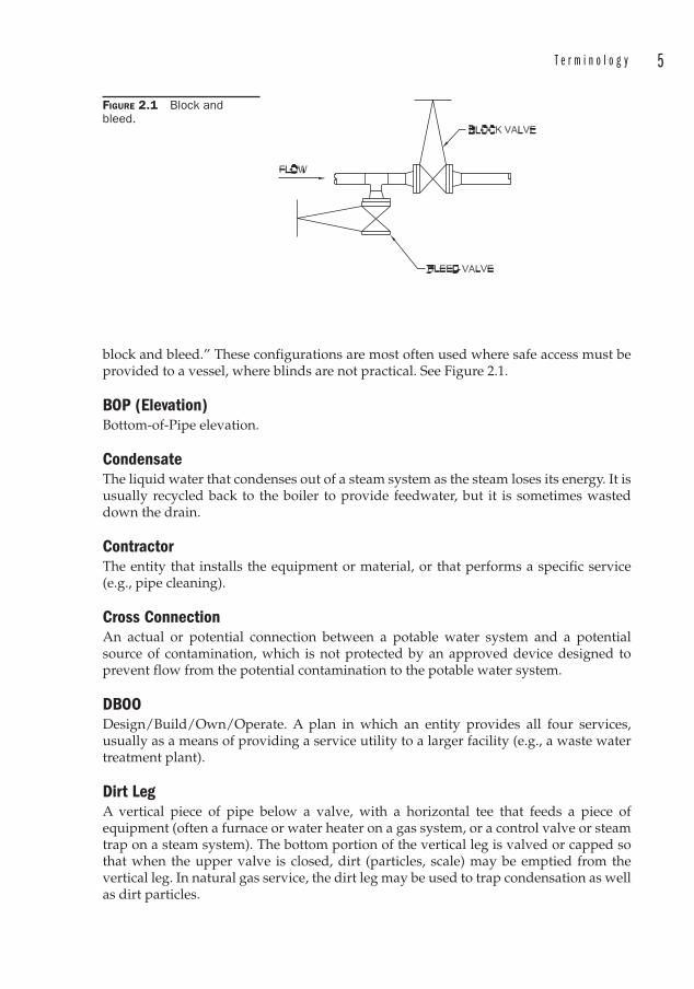
T e r m i n o l o g y 5
block and bleed.” These configurations are most often used where safe access must be provided to a vessel, where blinds are not practical. See Figure 2.1.
BOP (Elevation)Bottom-of-Pipe elevation.
CondensateThe liquid water that condenses out of a steam system as the steam loses its energy. It is usually recycled back to the boiler to provide feedwater, but it is sometimes wasted down the drain.
ContractorThe entity that installs the equipment or material, or that performs a specific service (e.g., pipe cleaning).
Cross ConnectionAn actual or potential connection between a potable water system and a potential source of contamination, which is not protected by an approved device designed to prevent flow from the potential contamination to the potable water system.
DBOODesign/Build/Own/Operate. A plan in which an entity provides all four services, usually as a means of providing a service utility to a larger facility (e.g., a waste water treatment plant).
Dirt LegA vertical piece of pipe below a valve, with a horizontal tee that feeds a piece of equipment (often a furnace or water heater on a gas system, or a control valve or steam trap on a steam system). The bottom portion of the vertical leg is valved or capped so that when the upper valve is closed, dirt (particles, scale) may be emptied from the vertical leg. In natural gas service, the dirt leg may be used to trap condensation as well as dirt particles.
FIGURE 2.1 Block and bleed.
6 C h a p t e r 2
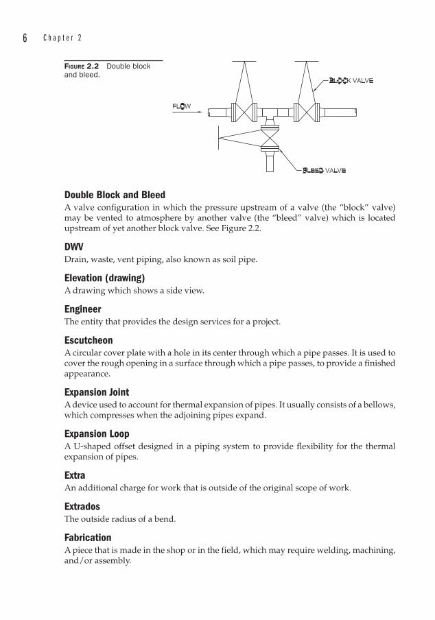
Double Block and BleedA valve configuration in which the pressure upstream of a valve (the “block” valve) may be vented to atmosphere by another valve (the “bleed” valve) which is located upstream of yet another block valve. See Figure 2.2.
DWVDrain, waste, vent piping, also known as soil pipe.
Elevation (drawing)A drawing which shows a side view.
EngineerThe entity that provides the design services for a project.
EscutcheonA circular cover plate with a hole in its center through which a pipe passes. It is used to cover the rough opening in a surface through which a pipe passes, to provide a finished appearance.
Expansion JointA device used to account for thermal expansion of pipes. It usually consists of a bellows, which compresses when the adjoining pipes expand.
Expansion LoopA U-shaped offset designed in a piping system to provide flexibility for the thermal expansion of pipes.
ExtraAn additional charge for work that is outside of the original scope of work.
ExtradosThe outside radius of a bend.
FabricationA piece that is made in the shop or in the field, which may require welding, machining, and/or assembly.
FIGURE 2.2 Double block and bleed.
T e r m i n o l o g y 7
Fire LoopAn underground water line outside the perimeter of a building. Part of the fire protection system, it provides water to the hydrants and may also supply the interior fire sprinkler system.
FittingA manufactured item that is used in a piping system to conveniently change the size or direction of the pipe. Examples are elbows, reducers, plugs, caps, and bushings.
Flood Level RimThe level of the edge of a receptacle from which water overflows.
Flow DiagramA drawing that shows the general flow characteristics of a piping system, including flowrate, temperature, and other parameters. Used to develop the P&IDs.
Fluid DynamicsThe study of how fluids behave in motion.
Gate ValveA type of valve used for on/off applications. It consists of a plate that enters the fluid stream, seating against the valve body interior to provide a tight seal.
Globe ValveA type of valve used for throttling and on/off applications. It consists of a disc mounted on the end of the valve stem. The disc rises and falls against a seat, effecting a seal or a variable opening which can be used to throttle the flow.
GreenfieldAn undeveloped site for new construction.
HAZOPHAZard and Operability analysis. A systematic means of identifying potential hazards so that they may be eliminated or mitigated.
HeadPressure, converted into feet of water. Used for determining pressure requirements of pumps.
HeaderA pipe that contains branch connections. Also known as the “run” pipe.
HVACHeating Ventilation and Air Conditioning.
HydraulicsThe study of how liquids behave at rest or in motion.
8 C h a p t e r 2
HydronicPiping that relates to hot and cold water in an HVAC system, and is used exclusively for heat transfer.
IDInside Diameter
Indirect ConnectionA waste pipe that does not attach to the receptacle that it discharges into.
IntradosThe inside radius of a bend.
Invert ElevationThe elevation of the bottom of a formed (concrete or otherwise) trench or inside of a gravity drain pipe at the 6 o’clock position.
LateralA type of tee fitting in which the angle formed between the run pipe and the branch pipe is less than 90 degrees.
LavatoryA sink with hot and cold water fixtures, and a drain to a sanitary sewer system.
Make-UpThe critical dimension of a threaded fitting.
MAWP“Maximum Allowable Working Pressure.” The MAWP is the maximum working pressure of the weakest component of a vessel.
Mfg“Manufacturing.” Not to be confused with “manufacturer.”
Mfr“Manufacturer.”
MMA designation for “million.” Since M is the Roman numeral for 1000, MM is one-thousand thousands, or one million. For example a 2 MM tank has a capacity of 2 million gallons. Care should be exercised since some industries use M for million.
MOC“Material of construction.”
NBEPNonboiler external piping.
T e r m i n o l o g y 9
NDTNon-destructive testing.
NominalA term used to indicate that something is “named” or called something. For instance, a standard 6 in diameter pipe has two pertinent diameters, neither of which is actually 6 in. The OD is 6.625 in, and the ID is 6.065 in. We say that the “nominal” diameter is 6 in. That is, we “call” it 6 in diameter as a matter of convenience, even though it is not exactly 6 in.
ODOutside diameter.
OS&YOutside stem and yoke. A type of gate or globe valve in which the stem nut is held by two arms (the yoke), which rise out of the valve body.
OwnerThe entity for whom the project is being developed. Usually also the operator of the facility.
P&IDPiping and Instrumentation Diagram.
PFDProcess Flow Diagram. A drawing that shows the major equipment and general flow characteristics of a piping system. The PFD usually indicates flowrates and temperatures. Used to develop the P&IDs.
PlanA drawing which depicts the overhead view.
PlaypipeA type of fire hose nozzle with a lever-actuated shut-off.
Pop-Off ValveSame as a safety valve. An automatic pressure relieving device activated by the static pressure upstream of the valve, and characterized by the rapid, full-opening of the valve. May be used for steam, gas, or vapor service.
Pressure Relief ValveA pressure relief device designed to reclose and prevent further venting of fluid after normal conditions have been restored. This is the generic term for any relief valve, whether it pops open or opens in proportion to the increase in pressure above the opening pressure.
10 C h a p t e r 2
PupA short length of pipe welded between two other lengths. Often used as a repair for a ruptured portion of piping.
Quad-StenciledA pipe labeled (stenciled) with four different specifications, meaning that it satisfies the requirements of any of the four specifications.
ReducerA fitting that is used to change the size (diameter) of a pipe. Sometimes referred to as an increaser by the uninformed. The size is always stated as (larger diameter) � (smaller diameter).
Relief ValveAn automatic pressure-relieving device activated by the static pressure upstream of the valve, which opens in proportion to the increase in pressure above the opening pressure.
Re-PadA reinforcing pad. A ring placed around a branch connection in order to add strength to the connection between the run pipe and the branch pipe.
Rising StemA type of gate or globe valve in which the position of the orifice (open or closed) can be determined by examining the tip of the threaded stem. Compare with non-rising stem.
RTJRing type joint. A type of flange with a grooved face to accept a ring gasket, common in the oil patch.
Rupture DiskA pressure relief device that is non-reclosing. It consists of a thin disk held between two flanges. When the pressure reaches a set limit, the rupture disk is designed to rupture, relieving the pressure.
SafeguardingProviding protective measures to minimize the risk of accidental damage to piping, or to mitigate the consequences of a possible pipe failure. See ASME B31.3, Appendix G.
Safety Relief ValveA pressure relief valve activated by the static pressure upstream of the valve, which either opens rapidly (like a safety or pop-off valve), or opens in proportion to the increase in pressure above the opening pressure (like a relief valve).
T e r m i n o l o g y 11
Safety ValveAn automatic pressure relieving device activated by the static pressure upstream of the valve, and characterized by the rapid, full-opening of the valve. May be used for steam, gas, or vapor service. Also referred to as a pop-off valve.
ScheduleA nominal number which designates the pipe wall thickness.
SleeperA type of pipe support at grade upon which the pipe rests.
SlurryA liquid that contains particles in suspension.
SMACNASheet Metal and Air Conditioning Contractor’s National Association. See www.smacna.org.
Soil StackA stack that conveys fecal waste.
SoleplateSee “Baseplate.”
Sovent®A trade name for a proprietary sanitary sewage system.
SpecialtyA manufactured item that performs a special function but is neither a valve nor a fitting. Examples include air vents, vacuum breakers, and strainers.
SpoolOriginally a length of pipe with a flange on both ends, it has come to mean any pre-fabricated piece of pipe of any configuration, whether or not there are flanges on the ends.
StackA vertical pipe in a drainage system. It may be a vent, a soil pipe, a rainwater pipe, or other waste pipe.
StanchionAn upright pipe support.

12 C h a p t e r 2
Steam TrapAn automatic valve used to remove condensate from a steam system.
STPStandard Temperature and Pressure of air, defined by the International Union of Pure and Applied Chemistry as an absolute pressure of 1 bar (100 kPa or 14.5038 psia) and a temperature of 273.15K (0°C or 32°F). There is no universally accepted definition of STP in industry, so it is necessary to define this term in detail.
SwageA forged fitting that reduces the size (diameter) of a pipe. It is longer than a reducer, and usually threaded on one end. Sometimes spelled swedge by the uninformed, due to the common mispronunciation.
SwedgeCommon mispronunciation of “swage.” See “Swage.”
Take-outThe dimension of a valve or fitting that must be accounted for in the design and fabrication of a piping system. For instance, on a valve, it is the distance between the raised faces of the flanges. For threaded fittings it is also referred to as “make-up.”
ThrottleTo modulate the flow in a pipeline with a valve.
TrimIn reference to boilers, trim consists of valves, fittings, gages, or appurtenances installed on a boiler to provide control. Trim usually refers to safety valves, try cocks, low water cutoff switches, and water columns.
In reference to valves, trim consists of the seat rings, disk or facing of the disk, stem, and stem guide sleeves (the wearing surfaces).
Tri-StenciledA pipe labeled (stenciled) with three different specifications, meaning that it satisfies the requirements of any of the three specifications.
ValveA device that is used to shut off or throttle the flow through a pipe.
Water-Distribution PipingThe piping inside a building that delivers both hot and cold water to plumbing fixtures.
Water-Service PipingPiping which extends from a potable water source to the interior of a building.
T e r m i n o l o g y 13
WeightSimilar to “schedule,” the “weight” is a nominal designation used to identify pipe wall thickness.
WeldmentA steel structure that is bonded by welding. Usually refers to the piece prior to any machining.
Weld-o-let®A type of branch connection that welds onto the run pipe. Bonney Forge owns the trademark to the name “Weld-o-let®.”
Wet VentA plumbing vent that also discharges waste water.
WOG“Water-Oil-Gas.” A designation that a fitting is suitable for these services, usually used with a specified pressure rating.
WorkabilityA characteristic that describes in relative terms the ability of a metal to be plastically deformed without fracturing.
WroughtPast participle of “to work,” hence, another name for “forged.”
WSP“Working steam pressure.” A designation that a fitting is suitable for steam service at a specified pressure rating.

This page intentionally left blank

15
CHAPTER 3Reference Materials
There are many excellent reference materials available to the piping engineer. Some are out of print, but still available in libraries or tucked away in the dusky recesses of a retired engineer’s desk.
1. Piping Handbook, Mohinder L. Nayyar, McGraw-Hill, Inc., ISBN 0-07-046881-8. This handbook covers piping fundamentals, various types of piping systems, and does a good job of covering the various ASTM piping specs and ASME piping codes. This is a massive volume. The fifth and earlier editions were edited by Crocker and King, and are equally good references.
2. Pipe Fitters Handbook, Grinnell Supply Sales Company. This was a pocket reference book that used to be available from Grinnell. It contains comprehensive tables of pipe sizes, wall thicknesses, and take-out dimensions for fittings, but is now out-of-print.
3. NAVCO Piping Datalog, National Valve and Manufacturing Company, Pittsburgh, PA. A favorite among piping engineers and designers, this out-of-print booklet contains a wealth of data pertaining to pipes and fittings.
4. Facility Piping Systems Handbook, Michael Frankel, McGraw-Hill, Inc., ISBN 0-07-021891-9. Another excellent reference for various system types encountered in industrial, commercial, and institutional settings.
5. National Plumbing Codes Handbook, R. Dodge Woodson, McGraw-Hill, Inc., ISBN 0-07-071769-9. This is an excellent reference for plumbing projects. It provides a good summary of the various plumbing codes, as well as information useful to those studying to take the plumbing license exam.
6. Piping and Pipe Support Systems, Paul R. Smith and Thomas J. Van Laan, McGraw-Hill, Inc., ISBN 0-07-058931-3. This reference provides insight into the codes specific to performing stress analyses of piping systems.
16 C h a p t e r 3
7. Marks’ Standard Handbook for Mechanical Engineers, Baumeister, Avallone, and Baumeister, McGraw-Hill, Inc., ISBN 0-07-004123-7. This encyclopedic reference contains a wealth of information concerning mechanical systems and materials.
8. Structural steel shapes catalogs published by any of the steel companies that roll structural steel. These catalogs are invaluable in the field for identifying the sizes of steel members and for detailing pipe supports.
9. Codes and Standards Training Institute (CASTI) publishes a variety of guide books including several that pertain to the ASME piping codes.
10. NIBCO Chemical Resistance Guide. Available from NIBCO, this reference provides excellent data regarding metals, plastics, and elastomers, and their ability to resist deterioration when exposed to a lengthy list of fluids.
11. Goulds Pump Manual. Aside from pump performance and selection data, this manual offers excellent design advice for centrifugal pump installations.
17
CHAPTER 4Piping Codes
I once worked on a pulp and paper project in western Canada. The consulting firm I worked for was designing the piping for an evaporator set. Evaporators take the black liquor that is produced in the cooking of the wood fibers (the pulping process) and evaporate most of the water away, leaving a flammable liquid that can be burned in boilers to produce steam. The process also recovers most of the chemicals used in the pulping process.
We had about seven large stainless steel vessels that had nozzles protruding at all kinds of odd angles. Our piping was designed to attach to these nozzles. The piping spools had been prefabricated, and due to some problems with the way the nozzles were fabricated, the contractor was having trouble with the fit-up. The nozzles had been fabricated out of plate, and when they were rolled the ends were out of plane. It really was a poorly made fitting, and demanded a lot of grinding to mate with the adjoining pipe.
The contractor wanted a cost extra to cut off the nozzles and reweld a new longer length of pipe, which would cause a redesign of our piping.
I was the site engineer and suggested that the contractor cut the nozzle back a bit so that it would be in the same plane, and then insert a short pup to which the remainder of my piping could be welded.
“You can’t do that! That’s against code! No pup length can be less than half of the pipe diameter.”
I didn’t have a copy of the “code,” and I didn’t challenge the contractor to cite the code reference of which he spoke. Had I bothered to ask him the details of the particular code, I would have learned that he did not know. He couldn’t have known, because there is no such code that prohibits welding a short pup .
Many contractors are code-savvy; many are not. To cite the codes is to speak with authority. It can be intimidating to challenge someone who appears to stand on firmer technical ground. But very often when you challenge someone to produce the code reference, you will find that it does not exist.
Many contractors and engineers have been trained to believe that something is part of a code when in fact it is not. They were told early in their career that something is code, or something violates a code. So without consulting the appropriate code to determine the validity of such a claim, it becomes part of the prejudices and superstitions that they bring to the job site. In the case of a pipe fitter, who could blame him for not consulting a code?
18 C h a p t e r 4
Well, why have codes in the first place?Piping codes, like the Boiler and Pressure Vessel Code and National
Electric Code have evolved over time in response to the need to continuously improve safety. Some of the ASME codes can trace their development back to historic disasters like the explosion of the steamship USS Sultana , which exploded on April 27, 1865 as it was transporting Union POW survivors from the Confederate South. Estimates range from 1300 to 1900 souls lost when one of the boilers exploded.
Another episode occurred in Boston on January 15, 1919, when a 2.3 MM gallon molasses tank ruptured, spewing its contents through the streets to a depth of 2 to 3 ft and killing 21 people. It is said that you can still smell molasses in the area to this day.
Incidents like these spawned public sentiment that “there ought to be a law,” and so were born certain codes that regulate the design, manufacture, and operation of facilities that may pose a hazard to the public.
The codes, however, are not themselves “laws.” Legislative bodies may adopt a code, or reference a code in a law, thereby requiring owners of equipment to abide by that particular code. Prudent engineers will contact the Authority Having Jurisdiction (AHJ) if they are uncertain about what codes must be applied.
But consider a manufacturing facility that may be staffed by unsophisticated personnel, who are nevertheless conscientious, at least in their desire to provide a profitable operation for the owners. Let’s assume that the plant has undergone an evolution of updates, modifications, and expansions throughout the years. Perhaps there is no actual engineering staff. So there is a good chance that the plant personnel do not consult with the AHJ whenever there is a new modification. It doesn’t take a lot of imagination to envision a scenario in which a piping failure might lead to property damage or worse.
There are many different piping codes in use throughout the world. These codes may be divided into the following basic groups:
1. Plumbing codes, intended to protect the public against unsanitary conditions.
2. Gas codes, intended to protect the public from hazardous fumes, fires, and explosions.
3. Industrial codes, intended to protect facilities and those working in them from catastrophic failures.
The location of the installation in question determines which plumbing and gas codes are to be applied. There is not a lot of difference between them, but there may be some differences, and local Authorities Having Jurisdiction (AHJ) should be consulted to determine which specific codes apply. Further, there may be amendments to the codes, which will be provided by the AHJ.
There has recently been a trend to standardize these codes within the U.S. In 1994, the International Code Council (ICC) was established as a nonprofit organization dedicated to developing a single set of comprehensive and coordinated national codes. Previously, there had been three code models in use throughout the U.S.:
• Building Officials and Code Administrators (BOCA)
• International Conference of Building Officials (ICBO)
• Southern Building Code Congress International (SBCCI).
P i p i n g C o d e s 19
These organizations created the ICC to resolve the technical disparities among the three sets of model codes.
Some of these codes may still be in force in various locations, so you should always check with the AHJ to determine what code needs to be applied to your project.
The newer, comprehensive code models developed by ICC are:
• International Building Code
• International Fire Code
• International Plumbing Code
• International Fuel Gas Code
• International Mechanical Code
• International Private Sewage Disposal Code
• International Residential Code – One and Two-Family Dwellings
• International Electrical Code
• International Energy Conservation Code
• International Property Maintenance Code
• International Zoning Code
• International Existing Building Code
• International Performance Code
• International Urban-Wildlife Interface Code.
Obviously, not all of these are piping codes. The list is provided for the sake of thoroughness.
The beauty of this system is that they are all fully compatible with each other, and represent an effort to unify the various other codes that have existed in the past. There are, however, some cumbersome features:
• Like all codes, you have to know where to look for the answer to the problem under investigation. For instance, you might reasonably expect that natural gas and hydronic piping would fall under the Mechanical Code. Not so. You will find hydronic piping and fuel oil in the Mechanical Code, but natural gas, being a fuel gas, will be found under the Fuel Gas Code.
• You really need access to most of these codes for them to be of any real value. The first six or seven are an absolute necessity, depending on what sort of projects you are involved in.
• Like all codes, they are written in codespeak, with lots of exceptions noted, and references to other parts of the code.
• As noted earlier, not all jurisdictions have adopted the ICC. You will still have to rely on the AHJ to tell you what codes are applicable.
When working on industrial piping projects, you may still have to rely on the plumbing and fuel gas codes mentioned above. However, any process piping or high pressure steam lines will lie outside the scope of the ICC codes. It is always a good idea to consult the “Scope” section of any code, to make sure that you are using the proper
20 C h a p t e r 4
code. The Scope section will tell you what the purpose of the code is, and may provide hints of where else you may search. If you are looking for high pressure steam lines in an ICC code book, you will quickly find that they are out of the ICC’s scope. Another set of codes is required.
Once again, there are many different piping codes for process and high-pressure lines in use throughout the world. Some countries, like Canada, take advantage of the considerable body of knowledge contained in the U.S. codes.
In the U.S. we follow the ASME Code for Pressure Piping, B31 . The code was first published in 1935 by the ASA (American Standards Association, now known as ANSI, the American National Standards Institute). The responsibility for developing the code was assigned to the ASME (American Society of Mechanical Engineers).
The ASME Code is so extensive that it was more convenient to break it up into several separate documents, which represent various industries. The code now consists of:
• B31.1 Power Piping
• B31.3 Process Piping
• B31.4 Pipeline Transportation Systems for Liquid Hydrocarbons and Other Liquids
• B31.5 Refrigeration Piping
• B31.8 Gas Transportation and Distribution Piping
• B31.9 Building Services Piping
• B31.11 Slurry Transportation Piping Systems.
Usually, by the time you get involved in a project, most of the piping specifications are written, and the codes to be used have been laid out in the specifications. But how did the engineer who wrote the specs know which codes to apply? Much of the time the answer lies in the codes themselves. The codes will explain what their intended scope is. But the codes are often applied to piping systems that are outside their scope.
This sounds like it might be a big problem, but the intelligent application of a piping code outside of its scope is not necessarily bad.
Let’s say that you are the engineer in charge of setting up the piping specs for a plant that is going to produce turbo-widgets for the up-and-coming e-widget industry. The heat is on to get into production right away, and the Chief Engineer is visiting you every 15 minutes to see if you have issued the specs for bid yet.
The first thing you notice after going to the code is that the e-widget industry is not represented. And you can’t find any mention of piping systems used in the production of turbo-widgets.
But you know that the plant uses air for the turbo-stamping lines, it uses water to cool the ovens that bake the widgets, it uses hydraulics for the presses that assemble the turbo-widgets, and there is also high-pressure steam for heating the reactor vessels that produce the proprietary widget compounds.
Like many projects of this type, a review of the available codes indicates that your choices are probably going to be limited to B31.1, B31.3, and B31.9. If you have some HVAC refrigerant lines, you might have to rely on B31.5 as well.
Some of these codes are more stringent than others. For instance, the allowable stresses for a given piping material is less in B31.1 and B31.9 than it is in B31.3. It’s the same material, made the same way. But the allowable stresses are different. In this respect, B31.1 and B31.9 are more stringent that B31.3.
P i p i n g C o d e s 21
You can always apply a more stringent code than is required for an application. Doing that does not compromise safety.
So you could specify the most stringent code for all of these services, but that might mean that your 2 in diameter low-pressure cooling water lines would be constructed out of Schedule 160 pipe. And by the way, since 2 in Schedule 160 pipe has a wall thickness of 0.344 in, the ID is reduced, and maybe you better use 3 in pipe so your head losses aren’t so high.
But the Chief Engineer isn’t crazy about the idea, since the piping costs are going to go way up. And a big part of engineering is doing the safest things in the most economical manner.
So you decide to use B31.1 for the steam and condensate systems, and B31.3 for everything else. You might want to use B31.1 for high-pressure hydraulics lines, especially if they are in an area where corrosion is a factor.
In the discussion that follows, the order in which the material is presented follows the same order as the Codes. The sections are numbered in accordance with the paragraphs as labeled in the Code. Referenced formulas and tables are identified as they are in the respective codes.
Note that this text is not a substitute for any of the codes. This text is provided to help the designer study and apply the codes. It is assumed that the code is available to the designer, and that this text is supplemental to it. We will not cover the codes completely, but will only hit the high points; those areas that are most likely to be encountered in a piping project, and those that can cause some of the most trouble.
Any code you use is going to be organized into numbered paragraphs. You will find that in applying a code, you will often be referred to other paragraphs elsewhere, especially where exceptions are involved. This can be frustrating, and it requires quite a bit of patience and perseverance. Working within the codes is a complicated process, and sometimes it may seem as though it is needlessly complicated. Perhaps the code writers may someday include the intent of what they want you to achieve in the codes. The Fine Print Notes in the National Electric Codes approach this philosophy, but it seems that all of the piping codes remain prescriptive. For example, the International Fuel Gas Code prohibits the use of cast iron bushings in Paragraph 403.10.4.5.2. If they explained that the reason they object to these fittings is because they are prone to undetected cracking during installation, then perhaps other installers would become aware of this problem as it applies to other applications or materials.
Of the seven B31 codes, most design engineers find that they spend most of their time dealing with B31.1, B31.3, and B31.9. The remainder of this chapter is confined to an overview of these codes.
ASME B31.1 Power Piping “Power piping ” in this case means the piping that is used around boilers. It is called power piping because often a boiler is used to make steam for power generation. This is done by converting pressure and temperature energy into kinetic energy in a turbine, which then produces electrical energy.
Mechanical engineering is the technical field associated with transforming energy into work. A steam generator is a perfect example of that. This code relates particularly to piping that would be found in electrical power plants, commercial and institutional plants, geothermal plants, and central heating and cooling plants.
This code is primarily concerned with the effects of temperature and pressure on the piping components.
22 C h a p t e r 4
100.1.2 ScopeAround a boiler, the scope of B31.1 begins where the boiler proper ends, at either:
1. The first circumferential weld joint
2. The face of the first flange
3. The first threaded joint
This piping is collectively referred to as “boiler external piping, ” since it is not considered part of the boiler.
Power piping may include steam, water, oil, gas, and air services. But it is not limited to these, and as mentioned before, there is nothing that says you cannot apply B31.1 to other piping systems unrelated to boilers or power generation, as long as they would not be better classified as within other piping codes, which may be more stringent.
100.1.3 Not in ScopeB31.1 does NOT apply to:
1. Components covered by the ASME Boiler and Pressure Vessel Code
2. Building heating and distribution steam and condensate piping if it designed for 15 psig or less
3. Building heating and distribution hot water piping if it is designed for 30 psig or less
4. Piping for hydraulic or pneumatic tools (and all of their components downstream of the first block valve off of the system header)
5. Piping for marine or other installations under federal control
6. Structural components
7. Tanks
8. Mechanical equipment
9. Instrumentation
102.3.2 Limits for Sustained and Displacement StressesThis section addresses cyclic stresses among other things. Note that the Stress Range Reduction Factors apply only to thermal cycling and NOT to pressure cycles.
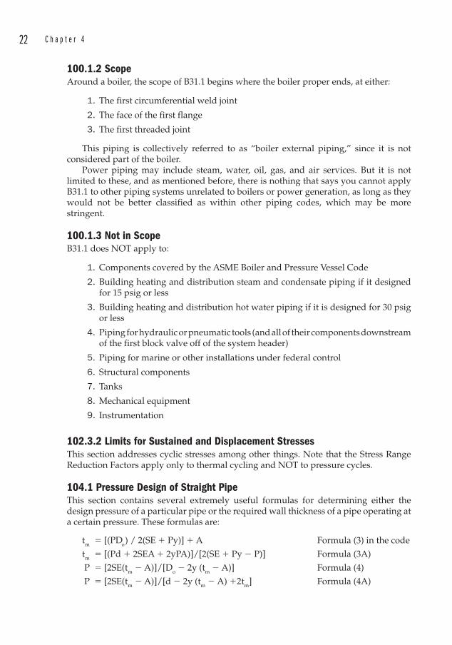
104.1 Pressure Design of Straight PipeThis section contains several extremely useful formulas for determining either the design pressure of a particular pipe or the required wall thickness of a pipe operating at a certain pressure. These formulas are:
tm � [(PDo) / 2(SE � Py)] � A Formula (3) in the code
tm � [(Pd � 2SEA � 2yPA)]/[2(SE � Py � P)] Formula (3A)
P � [2SE(tm � A)]/[Do � 2y (tm � A)] Formula (4)
P � [2SE(tm � A)]/[d � 2y (tm � A) �2tm] Formula (4A)
P i p i n g C o d e s 23
wheretm � Minimum Required Wall Thickness [in. or mm]1
Piping is generally purchased based on commercially available schedules or wall thicknesses (unless specially ordered, which is usually prohibitively expensive). These thicknesses must take into account the mill tolerance, which may be as much as 12.5 percent less than the nominal thickness.
P � Internal design gage pressure [psig or kPa (gage)]
The pressure is either given or solved for in the equations.
Do � Outside diameter of pipe [in or mm]
The outside diameter will be the OD of a commercially available pipe. An example of these data for carbon steel pipe can be found in Appendix A.1 of this text.
d � Inside diameter of pipe [in or mm]
The inside diameter will be the ID of a commercially available pipe.
S � Maximum Allowable Stress Values in Tension for the material at the design temperature [psi or kPa]
These values are tabulated in ASME B31.1, Appendix A. Note that they are dependent on the temperature to which the material will be exposed. This temperature is the metal temperature. This would normally be the temperature of the fluid in the pipe, but if a pipe was to be exposed to a high temperature externally, it would be the fluid temperature outside the pipe.
Note that the values tabulated in Appendix A include the Weld Joint Efficiencies and the Casting Factors . Therefore, the tabulated values are the values of S, SE, or SF. See General Note (f) at the end of each table.
E � Weld Joint Efficiency, shown in ASME B31.1, Appendix A. These values depend on the material used and the method of manufacture. Naturally, if the material is a cast product, there is no weld. In that case the Casting Factor F is used.
F � Casting Factor shown in ASME B31.1, Appendix A. Where a cast material is used, the casting factor F takes the place of E in the equations above. Like the weld joint efficiency, these values depend on the material used and the method of manufacture.
A � Additional thickness [in or mm]
This value is used to compensate for:
1. Material that is removed in fabricating mechanical joints (threading or grooving)
2. Increased mechanical strength of the piping
3. Erosion or corrosion allowance
4. Cast pipe tolerances.
1 Note that throughout this book we will make an effort to include both Imperial and metric units. Regardless of which system is utilized, the designer must always remain consistent in the use of the units chosen. Switching back and forth between systems of measure is not recommended. It is always recommended to include the units in any calculation so that they may be algebraically cancelled. This ensures that any appropriate conversion factors are applied within the calculation. See Example 4.1.
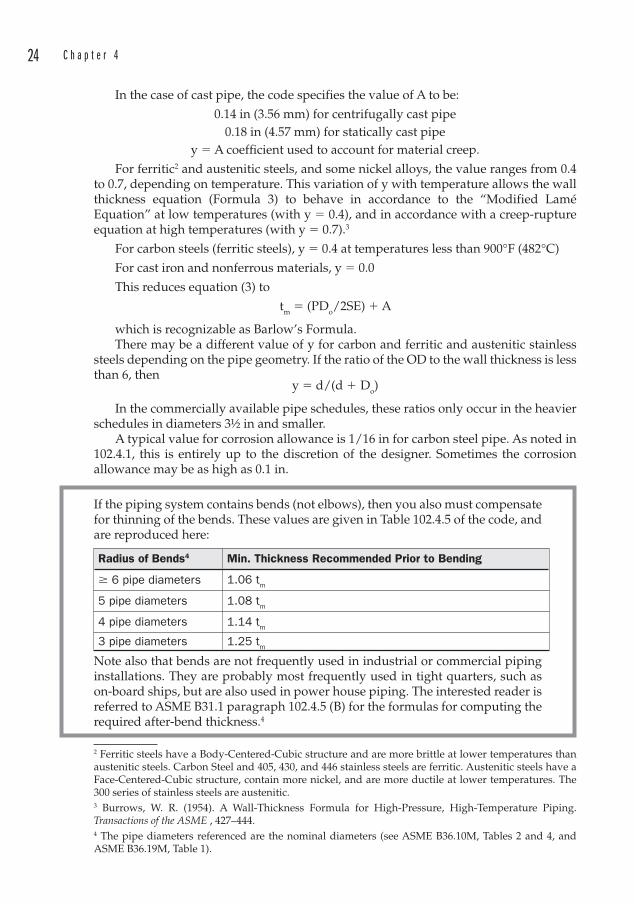
24 C h a p t e r 4
In the case of cast pipe, the code specifies the value of A to be:
0.14 in (3.56 mm) for centrifugally cast pipe0.18 in (4.57 mm) for statically cast pipe
y � A coeffi cient used to account for material creep.
For ferritic2 and austenitic steels, and some nickel alloys, the value ranges from 0.4 to 0.7, depending on temperature. This variation of y with temperature allows the wall thickness equation (Formula 3) to behave in accordance to the “Modified Lamé Equation” at low temperatures (with y � 0.4), and in accordance with a creep-rupture equation at high temperatures (with y � 0.7).3
For carbon steels (ferritic steels), y � 0.4 at temperatures less than 900°F (482°C)
For cast iron and nonferrous materials, y � 0.0
This reduces equation (3) to
tm � (PDo/2SE) � A
which is recognizable as Barlow’s Formula.There may be a different value of y for carbon and ferritic and austenitic stainless
steels depending on the pipe geometry. If the ratio of the OD to the wall thickness is less than 6, then
y � d/(d � Do)
In the commercially available pipe schedules, these ratios only occur in the heavier schedules in diameters 3½ in and smaller.
A typical value for corrosion allowance is 1/16 in for carbon steel pipe. As noted in 102.4.1, this is entirely up to the discretion of the designer. Sometimes the corrosion allowance may be as high as 0.1 in.
If the piping system contains bends (not elbows), then you also must compensate for thinning of the bends. These values are given in Table 102.4.5 of the code, and are reproduced here:
Radius of Bends4 Min. Thickness Recommended Prior to Bending
� 6 pipe diameters 1.06 tm
5 pipe diameters 1.08 tm
4 pipe diameters 1.14 tm
3 pipe diameters 1.25 tm
Note also that bends are not frequently used in industrial or commercial piping installations. They are probably most frequently used in tight quarters, such as on-board ships, but are also used in power house piping. The interested reader is referred to ASME B31.1 paragraph 102.4.5 (B) for the formulas for computing the required after-bend thickness.4
2 Ferritic steels have a Body-Centered-Cubic structure and are more brittle at lower temperatures than austenitic steels. Carbon Steel and 405, 430, and 446 stainless steels are ferritic. Austenitic steels have a Face-Centered-Cubic structure, contain more nickel, and are more ductile at lower temperatures. The 300 series of stainless steels are austenitic.3 Burrows, W. R. (1954). A Wall-Thickness Formula for High-Pressure, High-Temperature Piping. Transactions of the ASME , 427–444.4 The pipe diameters referenced are the nominal diameters (see ASME B36.10M, Tables 2 and 4, and ASME B36.19M, Table 1).
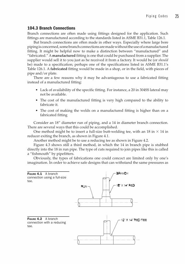
P i p i n g C o d e s 25
104.3 Branch Connections Branch connections are often made using fittings designed for the application. Such fittings are manufactured according to the standards listed in ASME B31.1, Table 126.1.
But branch connections are often made in other ways. Especially where large bore piping is concerned, some branch connections are made without the use of a manufactured fitting. It might be helpful now to make a distinction between “manufactured” and “fabricated.” A manufactured fitting is one that could be purchased from a supplier. The supplier would sell it to you just as he received it from a factory. It would be (or should be) made to a specification; perhaps one of the specifications listed in ASME B31.1’s Table 126.1. A fabricated fitting would be made in a shop, or in the field, with pieces of pipe and/or plate.
There are a few reasons why it may be advantageous to use a fabricated fitting instead of a manufactured fitting:
• Lack of availability of the specific fitting. For instance, a 20 in 304SS lateral may not be available.
• The cost of the manufactured fitting is very high compared to the ability to fabricate it.
• The cost of making the welds on a manufactured fitting is higher than on a fabricated fitting
Consider an 18” diameter run of piping, and a 14 in diameter branch connection. There are several ways that this could be accomplished.
One method might be to insert a full-size butt-welding tee, with an 18 in � 14 in reducer exiting the branch, as shown in Figure 4.1.
Another method might be to use a reducing tee as shown in Figure 4.2.Figure 4.3 shows still a third method, in which the 14 in branch pipe is stubbed
directly into the 18 in run pipe. The type of cuts required to join pipes like this is called a “fishmouth” by pipefitters.
Obviously, the types of fabrications one could concoct are limited only by one’s imagination. In order to achieve safe designs that can withstand the same pressures as
FIGURE 4.1 A branch connection using a full-size tee.
FIGURE 4.2 A branch connection with a reducing tee.
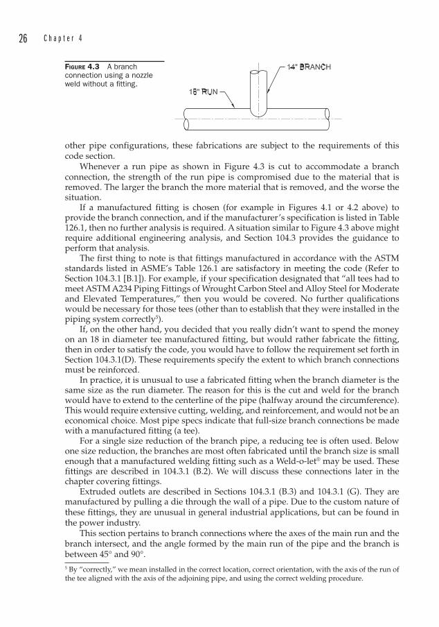
26 C h a p t e r 4
other pipe configurations, these fabrications are subject to the requirements of this code section.
Whenever a run pipe as shown in Figure 4.3 is cut to accommodate a branch connection, the strength of the run pipe is compromised due to the material that is removed. The larger the branch the more material that is removed, and the worse the situation.
If a manufactured fitting is chosen (for example in Figures 4.1 or 4.2 above) to provide the branch connection, and if the manufacturer’s specification is listed in Table 126.1, then no further analysis is required. A situation similar to Figure 4.3 above might require additional engineering analysis, and Section 104.3 provides the guidance to perform that analysis.
The first thing to note is that fittings manufactured in accordance with the ASTM standards listed in ASME’s Table 126.1 are satisfactory in meeting the code (Refer to Section 104.3.1 [B.1]). For example, if your specification designated that “all tees had to meet ASTM A234 Piping Fittings of Wrought Carbon Steel and Alloy Steel for Moderate and Elevated Temperatures,” then you would be covered. No further qualifications would be necessary for those tees (other than to establish that they were installed in the piping system correctly5).
If, on the other hand, you decided that you really didn’t want to spend the money on an 18 in diameter tee manufactured fitting, but would rather fabricate the fitting, then in order to satisfy the code, you would have to follow the requirement set forth in Section 104.3.1(D). These requirements specify the extent to which branch connections must be reinforced.
In practice, it is unusual to use a fabricated fitting when the branch diameter is the same size as the run diameter. The reason for this is the cut and weld for the branch would have to extend to the centerline of the pipe (halfway around the circumference). This would require extensive cutting, welding, and reinforcement, and would not be an economical choice. Most pipe specs indicate that full-size branch connections be made with a manufactured fitting (a tee).
For a single size reduction of the branch pipe, a reducing tee is often used. Below one size reduction, the branches are most often fabricated until the branch size is small enough that a manufactured welding fitting such as a Weld-o-let® may be used. These fittings are described in 104.3.1 (B.2). We will discuss these connections later in the chapter covering fittings.
Extruded outlets are described in Sections 104.3.1 (B.3) and 104.3.1 (G). They are manufactured by pulling a die through the wall of a pipe. Due to the custom nature of these fittings, they are unusual in general industrial applications, but can be found in the power industry.
This section pertains to branch connections where the axes of the main run and the branch intersect, and the angle formed by the main run of the pipe and the branch is between 45° and 90°. 5 By “correctly,” we mean installed in the correct location, correct orientation, with the axis of the run of the tee aligned with the axis of the adjoining pipe, and using the correct welding procedure.
FIGURE 4.3 A branch connection using a nozzle weld without a fi tting.
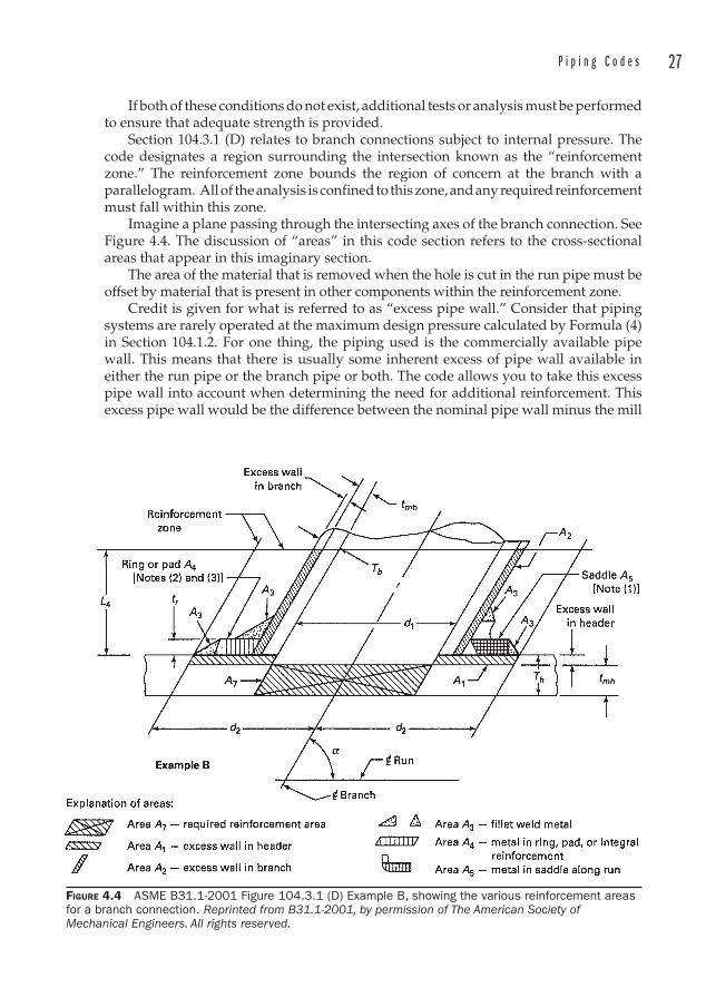
P i p i n g C o d e s 27
If both of these conditions do not exist, additional tests or analysis must be performed to ensure that adequate strength is provided.
Section 104.3.1 (D) relates to branch connections subject to internal pressure. The code designates a region surrounding the intersection known as the “reinforcement zone. ” The reinforcement zone bounds the region of concern at the branch with a parallelogram. All of the analysis is confined to this zone, and any required reinforcement must fall within this zone.
Imagine a plane passing through the intersecting axes of the branch connection. See Figure 4.4. The discussion of “areas” in this code section refers to the cross-sectional areas that appear in this imaginary section.
The area of the material that is removed when the hole is cut in the run pipe must be offset by material that is present in other components within the reinforcement zone.
Credit is given for what is referred to as “excess pipe wall. ” Consider that piping systems are rarely operated at the maximum design pressure calculated by Formula (4) in Section 104.1.2. For one thing, the piping used is the commercially available pipe wall. This means that there is usually some inherent excess of pipe wall available in either the run pipe or the branch pipe or both. The code allows you to take this excess pipe wall into account when determining the need for additional reinforcement. This excess pipe wall would be the difference between the nominal pipe wall minus the mill
FIGURE 4.4 ASME B31.1-2001 Figure 104.3.1 (D) Example B, showing the various reinforcement areas for a branch connection. Reprinted from B31.1-2001, by permission of The American Society of Mechanical Engineers. All rights reserved.
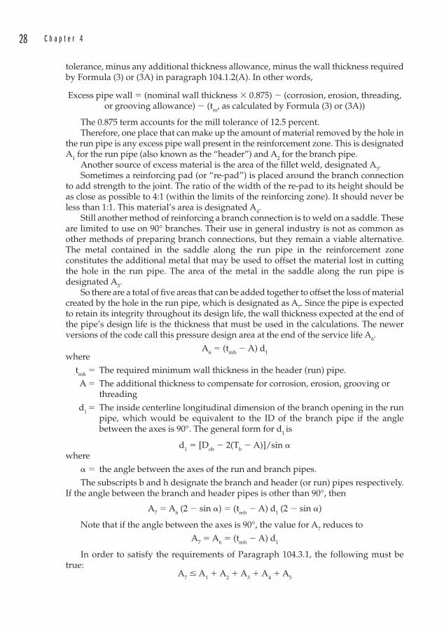
28 C h a p t e r 4
tolerance , minus any additional thickness allowance, minus the wall thickness required by Formula (3) or (3A) in paragraph 104.1.2(A). In other words,
Excess pipe wall � (nominal wall thickness � 0.875) � (corrosion, erosion, threading, or grooving allowance) � (tm, as calculated by Formula (3) or (3A))
The 0.875 term accounts for the mill tolerance of 12.5 percent.Therefore, one place that can make up the amount of material removed by the hole in
the run pipe is any excess pipe wall present in the reinforcement zone. This is designated A1 for the run pipe (also known as the “header”) and A2 for the branch pipe.
Another source of excess material is the area of the fillet weld, designated A3.Sometimes a reinforcing pad (or “re-pad”) is placed around the branch connection
to add strength to the joint. The ratio of the width of the re-pad to its height should be as close as possible to 4:1 (within the limits of the reinforcing zone). It should never be less than 1:1. This material’s area is designated A4.
Still another method of reinforcing a branch connection is to weld on a saddle. These are limited to use on 90° branches. Their use in general industry is not as common as other methods of preparing branch connections, but they remain a viable alternative. The metal contained in the saddle along the run pipe in the reinforcement zone constitutes the additional metal that may be used to offset the material lost in cutting the hole in the run pipe. The area of the metal in the saddle along the run pipe is designated A5.
So there are a total of five areas that can be added together to offset the loss of material created by the hole in the run pipe, which is designated as A7. Since the pipe is expected to retain its integrity throughout its design life, the wall thickness expected at the end of the pipe’s design life is the thickness that must be used in the calculations. The newer versions of the code call this pressure design area at the end of the service life A6.
A6 � (tmh � A) d1where
tmh � The required minimum wall thickness in the header (run) pipe.
A � The additional thickness to compensate for corrosion, erosion, grooving or threading
d1 � The inside centerline longitudinal dimension of the branch opening in the run pipe, which would be equivalent to the ID of the branch pipe if the angle between the axes is 90°. The general form for d1 is
d1 � [Dob � 2(Tb � A)]/sin �where
� � the angle between the axes of the run and branch pipes.
The subscripts b and h designate the branch and header (or run) pipes respectively.If the angle between the branch and header pipes is other than 90°, then
A7 � A6 (2 � sin �) � (tmh � A) d1 (2 � sin �)
Note that if the angle between the axes is 90°, the value for A7 reduces to
A7 � A6 � (tmh � A) d1
In order to satisfy the requirements of Paragraph 104.3.1, the following must be true:
A7 � A1 � A2 � A3 � A4 � A5
P i p i n g C o d e s 29
Another way of stating this is that the required reinforcement area must be less than any combination of:
1. A1 � Area of any excess pipe wall contained in the run� (2d2 � d1)(Th � tmh)
2. A2 � Area of any excess pipe wall contained in the branch.� 2L4(Tb � tmb)/sin �
3. A3 � Area of any welds beyond the outside diameters of either the run or branch, or of weld attachments of pads, rings, or saddles.
4. A4 � Area provided by any rings, pads, or integral reinforcement.
5. A5 � Area provided by a saddle on a right angle connection.� (OD of saddle � Dob) tr
In practice, if you were using a saddle, you would not also have a re-pad, and vice-versa. Therefore, A4 and A5 can be considered mutually exclusive.
The code lists specific requirements for closely spaced branch connections, branch connections subject to external forces and moments.
The Pipe Fabrication Institute publishes worksheets (designated ES36) that aid in these calculations.
One of the piping projects I worked on was a high pressure descale system for a steel mill. These systems blast the scale from rolling operations off of the strip of steel as it passes through the rolling mills. The scale is removed through a combination of thermal shock and high velocity water jets. The water pressures may be in the 3000 to 4500 psi range. Obviously, great care must be taken to ensure a safe piping system.
We were having trouble finding available fittings for the descale piping, due to the very heavy wall thicknesses required by the piping code. The design pressure was 3900 psi, and we were using ASME B31.3. As usual, the design schedule was incredibly tight, and no one was in the mood to hear that the project might be delayed because the engineer was specifying hard-to-find materials. The equipment vendor took me aside and told me that my calculations were too conservative, since I had allowed for a mill tolerance of 87.5 percent of the published wall thicknesses, as required by the code.
“I worked in a pipe mill,” he told me, “and we got paid by how many tons of pipe we produced! I can tell you that the mills don’t skimp on wall thickness. It’s to their advantage to make the walls thicker since they sell by weight!”
An argument like that doesn’t carry much weight. You should avoid trouble by meeting or exceeding the code requirements.
Example 4.1Given: Design Pressure: 165 psigTemperature: 675°FService: Superheated Steam inside a powerhouseCode: ASME B31.1Design: A fabricated 4 in branch connection at 90°, coming off an 8 in diameter header.
30 C h a p t e r 4
Solution:Let’s assume that the material of construction is garden-variety carbon steel: A53
Grade A, ERW (electric resistance welded) pipe6.We must determine the minimum wall thicknesses of each of the pipes. From
Formula (3) in Section 104.1, we have
tm � [(PDo) / 2 (SE � Py)] � A
P and Do are given. From Table A-1 of B31.1, we find that the maximum allowable stress value for A53, Grade A, ERW pipe is 10.2 ksi from minus 20 to 650°F. However, our example has a temperature that is higher than 650°F. We are permitted to interpolate to arrive at the design stress. The value at 700°F is 9.9 ksi, so we will use SE � 10.05 ksi. The value of y is taken to be 0.4, since we are using carbon steel pipe.
Because we are working with carbon steel, we assume a corrosion allowance of 0.0625 in. This will ensure that the pipe will remain serviceable at the design pressure over a period of time that it will take for the pipe to corrode 1/16 in from the inside diameter. If the line is located in a harsh environment without any maintenance, we might choose to provide an additional corrosion allowance to the outside of the pipe. For our example, the line is inside a building and protected from external corrosion. “Fitness for service ” calculations may be made during the life of the piping using ultrasonic thickness measurements taken at various points to monitor material lost due to corrosion or erosion.
Therefore, for the header
tmh � [(PDo) / 2 (SE � Py)] � A � (165 psig)(8.625 in) / 2[10,050 psi � (165 psig)(0.4)] � 0.0625 in � 0.070 in � 0.0625 in � 0.133 in
The minimum wall thickness that is commercially available for 8 in diameter CS pipe is Schedule 20, with a thickness of 0.250 in. This would be suitable, but Schedule 40 is the standard thickness (sometimes also called the “weight” of the pipe), so we choose Schedule 40 with a thickness of 0.322 in. We note that Schedule 40 could have a wall thickness as low as
0.322 in � 0.875 � 0.282 in due to the 12.5 percent mill tolerance on wall thickness.
This minimum wall thickness of the run pipe is known as Th.Therefore, by selecting Schedule 40, we see that we have an excess pipe wall of
0.282 in � 0.133 in � 0.149 in
We perform the same exercise for the branch:
tmb � [(PDo) / 2(SE � Py)] � A � (165 psig psi)(4.500 in) / 2[10,050 psi � (165 psig psi)(0.4)] � 0.0625 in � 0.037 in � 0.0625 in � 0.099 in
6 ASTM A53 Grade A is not suitable for prolonged exposure to temperatures above 800°F (427°C), since the carbon phase may be converted to graphite.
P i p i n g C o d e s 31
The minimum wall thickness that is commercially available for 4 in diameter pipe is Schedule 40 (standard weight), with a thickness of 0.237 in. But we note that with the mill tolerance , it could be as thin as
0.237 in � 0.875 � 0.207 in This value is known as Tb.We select Schedule 40, and note that the branch pipe has an excess pipe wall of
0.207 in � 0.099 in � 0.108 inWe may now calculate A7.
d1 � Inside diameter of the branch pipe � 4.026 in A7 � (tmh � A) d1
� (0.133 in � 0.0625 in) (4.026 in) � 0.284 in2
Now we examine the excess areas, and determine the need for reinforcements. We must first determine the bounds of the reinforcement zone.
d2 � The half-width of the reinforcing zone � The greater of d1 or (Tb � A) � (Th � A) � d1/2, but in no case
more than the outside diameter of the header pipe.
The OD of the header is 8.625 in and d1 � 4.026 in. The other term to check is:
(Tb � A) � (Th � A) � d1/2 � (0.207 in � 0.0625 in) �(0.282 in � 0.0625 in) � 4.026 in/2
� 0.145 in � 0.220 in � 2.013 in � 2.377 in
Therefore, d2 � 4.026 in. This establishes the width of the reinforcement zone. We must now find the height of the reinforcement zone, L4.
L4 is the smaller of 2.5 (Tb � A) � tr or 2.5 (Th � A), where tr is the thickness of a reinforcing pad, if used. If the branch attachment is a
manufactured connection, it may contain additional metal for reinforcing the connection. This is termed “integrally reinforced,” and if this is the case, then the value of tr is the height of a 60° right triangle whose perpendicular legs align with the ODs of the run and branch, and which lies completely within the area of the extra metal reinforcement.
In our example, we will presume that we will not have a re-pad. We already know that this is a fabricated piece, so we are not using an integrally reinforced connection. Therefore tr � 0 and
L4 � the smaller of 2.5 (0.207 in � 0.0625 in) � 0 � 0.361 in
OR 2.5 (0.282 in � 0.0625 in) � 0.549 in
Therefore, L4 � 0.361 in
A1 � (2d2 � d1)(Th � tmh) � [2(4.026 in) � 4.026 in](0.282 in � 0.133 in) � 0.600 in2
We see that this is already larger than A7, so we can stop here and be satisfied that the branch connection meets the code requirements.
But what if the problem had been at a much higher pressure?
32 C h a p t e r 4
Example 4.2Given: The same design and MOC as Example 4.1, but with a design pressure of 1000 psig. Use ASME B31.1. (The saturation temperature at P = 1000 psig is 546°F, so the steam is still superheated if it is at 675°F.)Solution:We start as before.
tmh � [(PDo) / 2 (SE � Py)] � A � (1000 psig)(8.625 in) / 2[10,050 psi � (1000(0.4)] � 0.0625 in � 0.413 in � 0.0625 in � 0.475 in
Schedule 100 has a wall thickness of 0.594 in. This is a very uncommon schedule, but for the purpose of this exercise we will use it. Under ordinary circumstances, an engineer would choose the next thicker common schedule, which in this case would be Schedule XXS (double-extra-strong) with a wall thickness of 0.875 in. But in this exercise, let’s see how much excess metal lies inside the reinforcement zone, and what must be done if it is not enough to satisfy the code.
Th � 0.594 in � 0.875 � 0.520 in
Therefore, by selecting Schedule 100, the excess pipe wall is
Th � tmh � 0.520 in � 0.475 in � 0.045 in
Again, we perform the same exercise for the branch:
tmb � [(PDo) / 2(SE � Py)] � A � (1000 psig)(4.500 in) / 2[10,050 psi � (1000 psig)(0.4)] � 0.0625 in � 0.215 in � 0.0625 in � 0.278 in
4 in diameter Schedule 80 (extra-strong) has a thickness of 0.337 in, so we choose it.
Tb � 0.337 in � 0.875 � 0.295 in
The branch pipe has an excess pipe wall of
Tb � tmb � 0.295 in � 0.278 in � 0.017 in
We now calculate the required reinforcement area A7.
d1 � inside diameter of the branch pipe � 3.826 in A7 � (tmh � A) d1
� (0.475 in � 0.0625 in) (3.826 in) � 1.578 in2
Now we examine the excess areas, and determine the need for reinforcements. We first determine the bounds of the reinforcement zone.
d2 � The half-width of the reinforcing zone � The greater of d1 or (Tb � A) � (Th � A) � d1/2, but in no case more
than the outside diameter of the header pipe
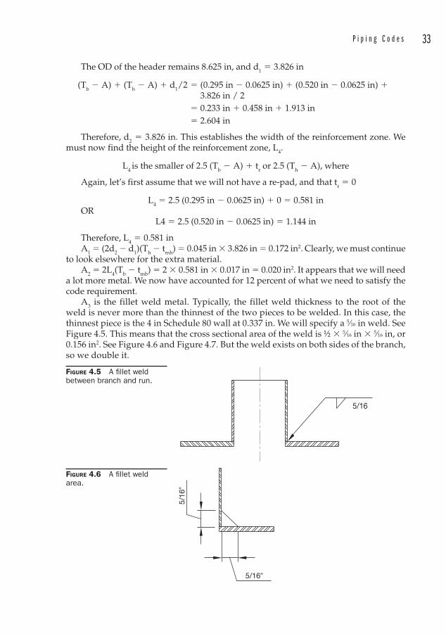
P i p i n g C o d e s 33
The OD of the header remains 8.625 in, and d1 � 3.826 in
(Tb � A) � (Th � A) � d1/2 � (0.295 in � 0.0625 in) � (0.520 in � 0.0625 in) � 3.826 in / 2
� 0.233 in � 0.458 in � 1.913 in � 2.604 in
Therefore, d2 � 3.826 in. This establishes the width of the reinforcement zone. We must now find the height of the reinforcement zone, L4.
L4 is the smaller of 2.5 (Tb � A) � tr or 2.5 (Th � A), where
Again, let’s first assume that we will not have a re-pad, and that tr � 0
L4 � 2.5 (0.295 in � 0.0625 in) � 0 � 0.581 inOR
L4 � 2.5 (0.520 in � 0.0625 in) � 1.144 in
Therefore, L4 � 0.581 inA1 � (2d2 � d1)(Th � tmh) � 0.045 in � 3.826 in � 0.172 in2. Clearly, we must continue
to look elsewhere for the extra material.A2 � 2L4(Tb � tmb) � 2 � 0.581 in � 0.017 in � 0.020 in2. It appears that we will need
a lot more metal. We now have accounted for 12 percent of what we need to satisfy the code requirement.
A3 is the fillet weld metal. Typically, the fillet weld thickness to the root of the weld is never more than the thinnest of the two pieces to be welded. In this case, the thinnest piece is the 4 in Schedule 80 wall at 0.337 in. We will specify a 5⁄16 in weld. See Figure 4.5. This means that the cross sectional area of the weld is ½ � 5⁄16 in � 5⁄16 in, or 0.156 in2. See Figure 4.6 and Figure 4.7. But the weld exists on both sides of the branch, so we double it.
FIGURE 4.5 A fi llet weld between branch and run.
5/16
5/16�
5/16
�
FIGURE 4.6 A fi llet weld area.

34 C h a p t e r 4
Our total excess metal at this point is now
0.172 in2 � 0.020 in2 � 2(0.156 in2) � 0.504 in2
We still need 1.578 in2 � 0.504 in2 � 1.074 in2
We need to add a reinforcing pad, preferably one with an aspect ratio of 4:1. We note that the half-width of the reinforcing zone is 3.826, and that the OD of the branch pipe is 4.5 in, leaving us with
3.826 in � 4.5 in/2 � 1.576 in
as a limit on the width of a re-pad. If we aim for a 4:1 aspect ratio on this (the aspect ratio recommended by the code), we can consider a plate with a thickness of 3⁄8 in and a width
FIGURE 4.7 Fillet weld size from ASME B31.1-2001, Figure 127.4.4 (A). Reprinted from B31.1-2001, by permission of The American Society of Mechanical Engineers. All rights reserved.
P i p i n g C o d e s 35
of 1.5 in. We recognize that from a practical standpoint, the ID of the re-pad has to be at least 5/8 in larger than the OD of the branch pipe to allow room for the fillet weld that connects the branch to the run pipe. This joint must be welded prior to the addition of the re-pad. This reduces the ID of the repad, which will leave us with a repad width of 1.188 in. The annulus between the ID of the repad and the OD of the branch pipe will be filled with weld, so as a convenience we can consider this weld metal to be part of the repad metal, even though technically it belongs to the A3 weld area.
This yields an additional area of
A4 � 2 � 0.375 in � 1.5 in � 1.125 in2
We now have
A7 � A1 � A2 � A3 � A4 � A5
1.578 in2 � 0.172 in2 � 0.020 in2 � 2(0.156) in2 � 1.125 in2 � 0 � 1.629 in2
This satisfies the code.
104.3.3 MitersMiters are perfectly acceptable fabricated fittings for pressure piping, if constructed in accordance with the requirements of Paragraph 104.3.3. Note however that they are usually only used in large bore piping where manufactured elbows are either unavailable or very expensive. Miters require much fit-up and welding. It is easier to simply purchase an elbow that conforms to one of the standards listed in Table 126.1 if these are available.
119 Expansion and Flexibility A review of this section of the code quickly reveals that the calculations for performing a flexibility and stress analysis are quite complex and cumbersome. These calculations are best performed with computer programs specifically designed to model and analyze piping systems.
There is, however, a formula which may be used to determine whether the more complex analysis is required. The conditions for applying this formula are:
• The piping system must be of uniform size
• The formula pertains only to ferrous systems
• It must be restrained only by two anchors (one at each end)
• It must be less than 7000 cycles during its life (which is fairly common)
• It should not be used with unequal leg U-bends (L/U � 2.5)
• It should not be used for large diameter, thin-wall pipe
• There is no assurance that the terminal reactions will be acceptably low.
If the above caveats are met, then the piping system requires no additional stress analysis if it satisfies the following equation:
DY/(L-U)2 � 30 SA/EC for Imperial units, orDY/(L-U)2 � 208,000 SA/EC for metric units
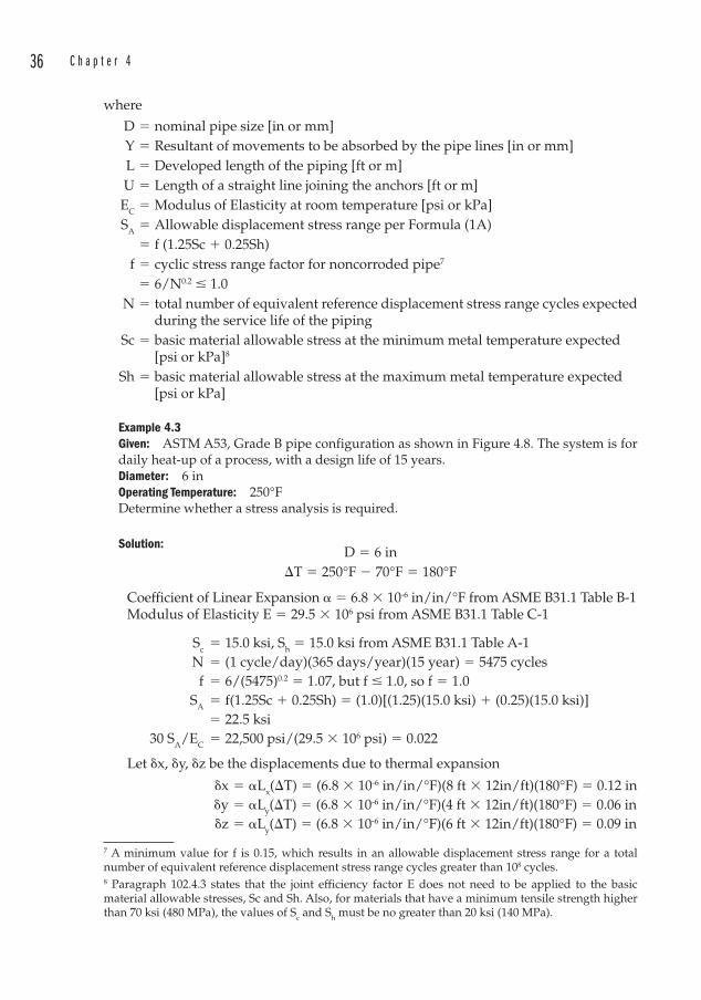
36 C h a p t e r 4
where
D � nominal pipe size [in or mm] Y � Resultant of movements to be absorbed by the pipe lines [in or mm] L � Developed length of the piping [ft or m] U � Length of a straight line joining the anchors [ft or m] EC � Modulus of Elasticity at room temperature [psi or kPa] SA � Allowable displacement stress range per Formula (1A) � f (1.25Sc � 0.25Sh) f � cyclic stress range factor for noncorroded pipe7 � 6/N0.2 � 1.0 N � total number of equivalent reference displacement stress range cycles expected
during the service life of the piping Sc � basic material allowable stress at the minimum metal temperature expected
[psi or kPa]8
Sh � basic material allowable stress at the maximum metal temperature expected[psi or kPa]
Example 4.3Given: ASTM A53, Grade B pipe configuration as shown in Figure 4.8. The system is for daily heat-up of a process, with a design life of 15 years.Diameter: 6 inOperating Temperature: 250°FDetermine whether a stress analysis is required.
Solution:D � 6 in
T � 250°F � 70°F � 180°F
Coefficient of Linear Expansion � � 6.8 � 10-6 in/in/°F from ASME B31.1 Table B-1Modulus of Elasticity E � 29.5 � 106 psi from ASME B31.1 Table C-1
Sc � 15.0 ksi, Sh � 15.0 ksi from ASME B31.1 Table A-1 N � (1 cycle/day)(365 days/year)(15 year) � 5475 cycles f � 6/(5475)0.2 � 1.07, but f � 1.0, so f � 1.0 SA � f(1.25Sc � 0.25Sh) � (1.0)[(1.25)(15.0 ksi) � (0.25)(15.0 ksi)] � 22.5 ksi 30 SA/EC � 22,500 psi/(29.5 � 106 psi) � 0.022
Let x, y, z be the displacements due to thermal expansion
x � �Lx(T) � (6.8 � 10-6 in/in/°F)(8 ft � 12in/ft)(180°F) � 0.12 in y � �Ly(T) � (6.8 � 10-6 in/in/°F)(4 ft � 12in/ft)(180°F) � 0.06 in z � �Ly(T) � (6.8 � 10-6 in/in/°F)(6 ft � 12in/ft)(180°F) � 0.09 in
7 A minimum value for f is 0.15, which results in an allowable displacement stress range for a total number of equivalent reference displacement stress range cycles greater than 108 cycles.8 Paragraph 102.4.3 states that the joint efficiency factor E does not need to be applied to the basic material allowable stresses, Sc and Sh. Also, for materials that have a minimum tensile strength higher than 70 ksi (480 MPa), the values of Sc and Sh must be no greater than 20 ksi (140 MPa).
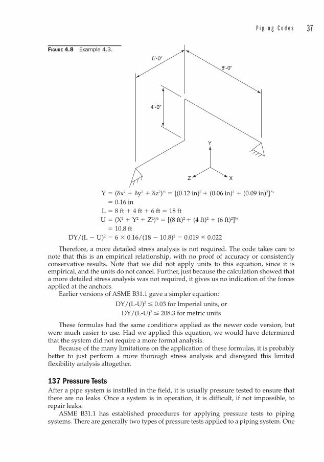
P i p i n g C o d e s 37
Y � (x2 � y2 � z2)½ � [(0.12 in)2 � (0.06 in)2 � (0.09 in)2] ½
� 0.16 in L � 8 ft � 4 ft � 6 ft � 18 ft U � (X2 � Y2 � Z2)½ � [(8 ft)2 � (4 ft)2 � (6 ft)2]½
� 10.8 ft DY/(L � U)2 � 6 � 0.16/(18 � 10.8)2 � 0.019 � 0.022
Therefore, a more detailed stress analysis is not required. The code takes care to note that this is an empirical relationship, with no proof of accuracy or consistently conservative results. Note that we did not apply units to this equation, since it is empirical, and the units do not cancel. Further, just because the calculation showed that a more detailed stress analysis was not required, it gives us no indication of the forces applied at the anchors.
Earlier versions of ASME B31.1 gave a simpler equation:
DY/(L-U)2 � 0.03 for Imperial units, orDY/(L-U)2 � 208.3 for metric units
These formulas had the same conditions applied as the newer code version, but were much easier to use. Had we applied this equation, we would have determined that the system did not require a more formal analysis.
Because of the many limitations on the application of these formulas, it is probably better to just perform a more thorough stress analysis and disregard this limited flexibility analysis altogether.
137 Pressure Tests After a pipe system is installed in the field, it is usually pressure tested to ensure that there are no leaks. Once a system is in operation, it is difficult, if not impossible, to repair leaks.
ASME B31.1 has established procedures for applying pressure tests to piping systems. There are generally two types of pressure tests applied to a piping system. One
FIGURE 4.8 Example 4.3.
6�-0�
8�-0�
4�-0�
Y
Z X
38 C h a p t e r 4
is a hydrotest and the other is a pneumatic test . The hydrotest is greatly preferred for the following reasons:
• Leaks are easier to locate.
• A hydrotest will lose pressure more quickly than a pneumatic test if leaks are present.
• Pneumatic tests are more dangerous, due to the stored pressure energy and possibility of rapid expansion should a failure occur.
On the other hand, if a piping system cannot tolerate trace levels of the testing medium (for instance, a medical oxygen system) then a pneumatic test is preferred.
137.4 Hydrostatic TestingIt is important to provide high point vents and low point drains in all piping systems to be hydrotested. The high point vents are to permit the venting of air, which if trapped during the hydrotest may result in fluctuating pressure levels during the test period. The drains are to allow the piping to be emptied of the test medium prior to filling with the operating fluid. (Low point drains are always a good idea though since they facilitate cleaning and maintenance.)
A hydrotest is to be held at a test pressure not less than 1.5 times the design pressure. The system should be able to hold the test pressure for at least 10 minutes, after which the pressure may be reduced to the design pressure while the system is examined for leaks. A test gauge should be sensitive enough to measure any loss of pressure due to leaks, especially if portions of the system are not visible for inspection.
The test medium for a hydrotest is usually clean water, unless another fluid is specified by the Owner. Care must be taken to select a medium that minimizes corrosion.
137.5 Pneumatic TestingThe test medium must be nonflammable and nontoxic. It is most often compressed air, but may also be nitrogen, especially for fuel gases or oxygen service. Note that compressed air often contains both oil and water, so care must be exercised in specifying an appropriate test medium.
A preliminary pneumatic test is often applied, holding the test pressure at 25 psig to locate leaks prior to testing at the test pressure. The test pressure for pneumatic tests is to be at least 1.2 but not more than 1.5 times the design pressure. The pneumatic test must be held at least 10 minutes, after which time it must be reduced to the lower of the design pressure or 100 psig (700 kPa gage) until an inspection for leaks is conducted.
If a high degree of sensitivity is required, other tests are available such as mass-spectrometer or halide tests.
Other portions of ASME B31.1 discuss various fittings, load cases, pipe hangers, systems specific to boiler piping, and welding requirements. We will follow-up on some of these areas in later portions of this book.
ASME B31.3 Process PipingThe term “process piping ” may be thought of as any piping that does not fall under the other B31 codes. It is generally considered to be the piping that one may find in chemical plants, refineries, paper mills, and other manufacturing plants.
P i p i n g C o d e s 39
This code is structured similar to B31.1 in that it is organized into chapters, parts, and paragraphs. Note that while the paragraphs of B31.1 are numbered in the 100s, those in B31.3 are numbered in the 300s. This convention follows throughout the B31 codes.
There are several very important concepts in this code that should be identified before we delve too far into the particulars. Because we have entered into the realm of process piping , it is necessary to recognize some of the inherent hazards associated with handling dangerous chemicals.
One concept is “damaging to human tissue.” This describes a fluid that could cause irreversible damage to the skin, eyes, or mucous membranes unless the fluid is promptly flushed away with water, or medication or antidotes are administered promptly.
In many manufacturing facilities, you will see eyewash stations or emergency showers , or a device which is a combination of both. These have evolved over the years into fairly sophisticated units, which may have remote alarms if activated to alert plant personnel to the fact that someone is in trouble. The Occupational Safety and Health Administration 29 CFR 1910.151 states that “…where the eyes or body of any person may be exposed to injurious corrosive materials, suitable facilities for quick drenching or flushing of the eyes and body shall be provided within the work area for immediate emergency use.”
But what constitutes “suitable facilities?” The American National Standards Institute (ANSI) has developed a voluntary standard ANSI Z358.1 which recommends, among other things, that the shower be no more than 10 seconds walking time away from the location of the hazard without requiring the use of steps or ramps, that the water should be tepid, unless this would create an additional hazard due to acceleration of chemical reactions, and that the water be disposed of in a manner that will not create additional hazards. Tepid water can be mixed at the device using an ASSE 1071 device.
In practice, you may sometimes observe eyewash/shower units that have not been tested in years and that are covered with dirt and grime. This is an indication of a poorly maintained facility. The drains of eyewash and safety showers are often not piped to a sewer and many are not located near a floor drain. This may create some reluctance to test these devices. This is unfortunate, since the supply lines should be periodically flushed.
300.1 ScopeThe scope of this code includes all fluids. This scope specifically excludes the following:
1. Piping with an internal design pressure between 0 and 15 psi (105 kPa) 2. Power boilers and BEP which is required to be in accordance with B31.1
3. Tubes inside fired heaters
4. Pressure vessels, heat exchangers, pumps, or compressors.
300.2 DefinitionsThere are several very important definitions included in this paragraph under the term “fluid service”:
a) Category D fluids are those in which all of the following apply:1. The fluid is nonflammable, nontoxic, and not damaging to human tissue.2. The design pressure does not exceed 150 psig (1035 kPa).3. The design temperature is between -20°F and 366°F (-29°C and 186°C).
40 C h a p t e r 4
b) Category M fluids are those in which a single exposure to a very small quantity could lead to serious irreversible harm, even if prompt restorative measures are taken.
c) High pressure fluids are those in which the Owner has specified that the pressures will be in excess of that allowed by the ASME B16.5 PN420 (Class 2500) rating for the specified design temperature and material group.
d) Normal fluids are everything else that does not fit into the above categories. These are the fluids most often used with this code.
301 Design ConditionsThis section requires the designer to consider the various temperatures, pressures, and loads that the piping system may be subject to. While it is a good checklist, most of the items contained are common sense.
301.3.2 Uninsulated ComponentsThis paragraph describes how to determine the design temperature of uninsulated piping and components. Of particular interest is the description of how to determine component temperatures using the fluid temperature. The instructions indicate that for fluid temperatures above 150°F (65°C) the temperature for uninsulated components shall be no less than a certain percentage of the fluid temperature. For example, the temperature used for lap joint flanges shall be 85 percent of the fluid temperature.
Note that unless you use the absolute temperature in degrees Rankine or Kelvin, such a calculation has no meaning, since a percentage cannot be applied to the Fahrenheit or Celsius scales.
302 Design CriteriaNote that B31.3 also has a Table 326.1 that corresponds to B31.1’s Table 126.1. A comparison between the two tables shows that Table 126.1 is focused more on steel pipe and fittings, while Table 326.1 pertains more to nonmetallic pipe and fittings. The obvious reason is that process piping deals with more fluids that are corrosive to steel. In many cases, thermoplastics, thermosetting plastics, and resins will be more appropriate materials for the fluids handled in the purview of the process piping code.
This set of paragraphs states that if the components listed in Table 326.1 are rated for a specific temperature/pressure condition, then they are suitable for the design pressures and temperatures allowed by this code. If they have no specific temperature/pressure rating, but are instead based on the ratings of straight seamless pipe, then the component must be de-rated by 12.5 percent, less any mechanical and corrosion allowances.
In other words, you have to determine the minimum wall thickness of the straight pipe based on the design temperature and pressure, as well as the mechanical and corrosion allowances. Once you apply the mill tolerance of 12.5 percent, you will be safe in selecting a fitting that satisfies the same requirements as the straight pipe to which it is connected.
302.2.4 Allowances for Pressure and Temperature VariationsThere are paragraphs in both B31.1 and B31.3 that describe allowable deviations from operating conditions. These are called “allowances for pressure and temperature variations. ” The rules for such operating excursions are not complicated, but in
P i p i n g C o d e s 41
practice industrial users do not chart how often the operating pressures exceed the allowable pressures.
Most often, any pressure excursions are prevented through the use of pressure relief devices, such as pressure relief valves, pressure safety valves, or rupture disks.
Also, it is important to note that the allowable stresses are temperature dependent. So if there are temperature excursions (as allowed for in both B31.1 and B31.3) the allowable stress may vary. Unless someone has taken the trouble to build a database of the relationships between operating temperature and pressure, and allowable temperature and pressure, then the designer will be well-advised to base the design pressure on the MAXIMUM temperature that the system will ever see, and not to rely on the allowance for temperature variations.
Therefore, from a practical standpoint, it is best to not rely upon any allowances for temperature or pressure excursions above the design conditions. Choose your design conditions so that the temperature and pressure will not be exceeded.
304.1.1 Pressure Design of Straight PipeAs we noted above, paragraph 302 requires us to calculate the required wall thickness to satisfy the design temperature and pressure conditions. We did the same thing for B31.1. But B31.3 handles things a little differently.
tm � t � c Formula (2) in the code t � PD/2(SEW � PY) Formula (3a) t � P(d+2c)/2[SEW � P(1-Y)] Formula (3b)where
tm � Minimum required wall thickness [in or mm]. This minimum wall thickness
includes any mechanical, corrosion, or erosion allowances.If the piping system contains bends (not elbows), then you also must compensate
for thinning of the bends, as in ASME B31.1. Because this is not common, the interested reader is referred to ASME B31.3 Paragraph 304.2.1 for the formulas required to determine after-bend thicknesses
t � Pressure design thickness, as determined by any of the Formulas (3a) through (3b) [in or mm].
c � Mechanical, corrosion, or erosion allowances [in or mm]. Note that for unspecifi ed tolerances on thread or groove depth, the code specifi es that an additional 0.02 in (0.5 mm) shall be added to the depth of the cut to take the unspecifi ed tolerance into account.
T � Pipe wall thickness, either measured or minimum per purchase specifi cation [in or mm].
Unless specially ordered (which is usually prohibitively expensive) piping is generally purchased based on commercially available schedules (or wall thicknesses). These thicknesses must take into account the mill tolerance which may be as much as 12.5 percent less than the nominal thickness.
Therefore, under ordinary circumstances, the pipe wall thickness (T) will be 87.5 percent of the thickness of the listed schedule.
d � Inside diameter of pipe [in or mm]. P � Internal design gage pressure [psig or kPa (gage)]

42 C h a p t e r 4
The pressure is either given, or solved for in the equations.
D � Outside diameter of pipe [in or mm]
The outside diameter will be the OD of a commercially available pipe. Carbon steel pipe dimensions are shown in Appendix 1 of this text.
E � Quality Factor from ASME Table A-1A or A-1B. Table A-1A relates exclusively to castings. Table A-1B relates to longitudinal weld joints. The quality factor is a means of de-rating the pressure based on the material and method of manufacture. Thus, for A106 seamless pipe, the quality factor E � 1.00.
Casting quality factors may be increased if the procedures and inspections listed in ASME B31.3 Table 302.3.3C are utilized.
The quality factors are in place to account for imperfections in castings, such as inclusions and voids. Machining all of the surfaces of a casting to a finish of 250 micro inches (6.3 μm) improves the effectiveness of surface examinations such as magnetic particle, liquid penetrant, or ultrasonic examinations.
The Quality Factor E is analogous to the Weld Joint Efficiency E or Casting Factor F in B31.1. But note that the Quality Factor E in B31.3 is NOT included in the stress values provided in B31.3 Tables A-1 and A-2. See Paragraph 302.3.1(a).
S � Stress in material at the design temperature [psi or kPa].
These values are tabulated in ASME B31.3, Appendix A. Note that they are dependent on the temperature to which the material will be exposed. This temperature is the metal temperature. This would normally be the temperature of the fluid in the pipe, but if a pipe was to be exposed to a high temperature externally, it would be the fluid temperature outside the pipe. See also Paragrah 301.
Once again, note that the values tabulated in ASME B31.3 Appendix A DO NOT include the Quality Factors. Therefore, the tabulated values are only the values of S.
W � Weld Joint Strength Factor. This factor accounts for the long term strength of weld joints at elevated temperatures. In the absence of specifi c data such as creep testing, W is taken as 1.0 at temperatures of 950°F (510°C) and below. W falls linearly to 0.5 at 1500°F (815°C).
Y � A coeffi cient used to account for material creep, as in B31.1. The table of Y coeffi cients in B31.3 is virtually identical to the table given in B31.1. As pre-viously noted, the variation of Y with temperature allows the wall thick-ness equation to behave in accordance to the “Modifi ed Lamé Equation” at low temperatures (with Y � 0.4), and in accordance with a creep-rupture equation at high temperatures (with Y � 0.7).
The values are taken from Table 304.1.1 for t < D/6. For ductile metals (including steel), the value is 0.4 across the range of temperatures. For t � D/6,
Y � (d � 2c)/(D � d � 2c)
Note that the difference between Formulas (3a) and (3b) is that (3a) begins with the OD of the pipe, and (3b) begins with the ID of the pipe.
B31.3 Chapter VII deals with nonmetallic piping and piping lined with nonmetals. Paragraph A304 explains how to calculate minimum wall thicknesses in such cases. The method and equations closely parallel Paragraph 304.1.1. The Allowable Stresses are replaced with Hydrostatic Design Stresses for nonmetals in Table B-1.
P i p i n g C o d e s 43
Pressure design of high-pressure piping (pressures in excess of the Class 2500 rating for the design temperature and material group), is covered in Paragraph K304. The equations given use Table K-1 for the basic allowable stresses. These stresses are higher than those listed in Table A-1 for the same materials.
Until recent editions of the code introduced the Weld Joint Strength Reduction Factor W, the code permitted the use of a simpler Formula (3b) for calculating pressure design thickness:
t � PD/2SE
The computation was simpler and because the denominator did not contain the addition of the PY term, this led to consistently more conservative results. With the possibility of W � 1.0 in the equation, this formula could lead to less conservative pressure design thicknesses.
However, if the metal temperatures are less than 950°F (510°C) or in the absence of specific creep testing data, then W � 1.0 and this formula could still be applied with confidence.
304.3 Branch Connections Similar to B31.1, B31.3 permits fabrication of branch connections. We are faced with the following prerequisites:
1. The run pipe diameter-to-thickness ratio (Dh/Th) < 100 and the branch-to-run diameter ratio (Db/Dh) is not greater than 1.0. If we examine the tables of commercially-available pipe data, we see that the first condition in which we might see a diameter-to-thickness ratio in excess of 100 would be 24 in diameter Schedule 5S, which has a wall thickness of 0.218 in. For thicknesses above the standard wall thickness, there is little chance that the ratio will exceed 100. So it is clear that while this is an important consideration for large bore, thin wall pipes, it is a situation that most of us are not likely to encounter. Looking next at the requirement that the branch-to-run ratio is not greater than 1.0, we see that this means only that it is impossible to stub a larger branch onto a smaller run. And if we tried to do that, we might be inclined to reverse the names of the branch and run. In other words, the branch pipe is always the smaller diameter, unless they are both the same diameter. Whichever pipe is designated as the run pipe, must still satisfy (Dh/Th) < 100.
2. If Dh/Th � 100, the branch diameter Db has to be less than one-half the run diameter Dh.
3. The angle between the branch and run is at least 45°. See Figure 4.8. This is analogous to B31.1’s angle �. We will examine the similarities and differences between B31.1 and B31.3 regarding the branch connection calculations.
4. The axes of the branch and run pipe must intersect each other. This was also a requirement of B31.1.
Once the prerequisites are established, we can examine any requirements for reinforcing the branch connection.
44 C h a p t e r 4
Here is an example of how the codes complicate matters. The names assigned to the various reinforcing areas in B31.3 are different than those we examined in B31.1. See Table 4.1 for a comparison of the terminology as they pertain to branch connections.
For B31.3:
A1 � Required reinforcement area
� thd1 (2 � sin ) Formula (6) A2 � Area due to excess thickness in the run pipe wall � (2d2 � d1) (Th � th
� c) Formula (7) A3 � Area due to excess thickness in the branch pipe wall = 2L4 (Tb � tb � c) / sin Formula (8) A4 � Area provided by welds and attached reinforcements d1 � Effective length of run pipe removed at the branch � [Db � 2 (Tb � c)] / sin d2 � Half-width of the reinforcement zone � The greater of d1
or (Tb � c) � (Th � c) � d1/2, but not more than Dh
L4 � Height of the reinforcement zone = The lesser of 2.5 (Tb � c) � Tr or 2.5 (Th � c) Tr � Minimum thickness of re-pad or saddle made from pipe � Smaller of the angles between the intersecting axes of the Branch and
Run pipes
The subscripts b and h refer to the branch and run pipe (or header pipe) respectively.In order to satisfy the reinforcement requirements of B31.3,
A2 � A3 � A4 � A1 Formula (6a)
As in B31.1, we have a reinforcement zone bounded by the parallelogram shown in Figure 4.9. Also, as in B31.1, there are also specific requirements for closely spaced nozzles (overlapping reinforcement zones) and branch connections subject to external pressure, forces, or moments.
Let’s turn our attention to some examples so that we can compare B31.1 with B31.3.
Example 4.4We will use the same design parameters as Example 4.1, but will instead analyze it using the rules of B31.3.Given: Design Pressure: 165 psigTemperature: 675°FService: Superheated Steam inside a powerhouseCode: ASME B31.3Design: A fabricated 4 in branch connection at 90°, coming off an 8 in diameter header.
Solution:Again we assume that the material of construction is A53 Grade A, ERW (electric
resistance welded) pipe.We have to determine the required wall thickness of each pipe, by applying one of
the formulas in Section 304.1.2.By Formula (3a):
t � PD/2 (SEW � PY)
P and D are given, and we know that W � 1.0 since the temperature is less than 950°F. We need to obtain the values of S, E, and Y.

Piping Codes 45
FIGURE 4.9 Branch connection nomenclature from ASME B31.3-2006, Figure 304.4.4. Reprinted from B31.3-2006, by permission of The American Society of Mechanical Engineers. All rights reserved.
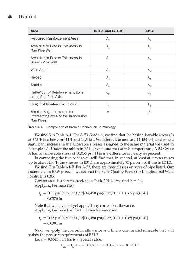
46 C h a p t e r 4
Area B31.1 and B31.9 B31.3
Required Reinforcement Area A7 A1
Area due to Excess Thickness in Run Pipe Wall
A1 A2
Area due to Excess Thickness in Branch Pipe Wall
A2 A3
Weld Area A3 A4
Re-pad A4 A4
Saddle A5 A4
Half-Width of Reinforcement Zone along Run Pipe Axis
d2 d2
Height of Reinforcement Zone L4 L4
Smaller Angle between the intersecting axes of the Branch and Run Pipes
�
TABLE 4.1 Comparison of Branch Connection Terminology
We find S in Table A-1. For A-53 Grade A, we find that the basic allowable stress (S) at 675°F lies between 14.4 and 14.5 ksi. We interpolate and use 14,450 psi, and note a significant increase in the allowable stresses assigned to the same material we used in Example 4.1. Under the tables in B31.1, we found that at this temperature, A-53 Grade A had an allowable stress of 10,050 psi. This is a difference of nearly 44 percent.
In comparing the two codes you will find that, in general, at least at temperatures up to about 200°F, the stresses in B31.1 are approximately 75 percent of those in B31.3.
We find E in Table A1-B. For A-53, there are three classes or types of pipe listed. Our example uses ERW pipe, so we see that the Basic Quality Factor for Longitudinal Weld Joints, Ej is 0.85.
Carbon steel is a ferritic steel, so in Table 304.1.1 we find Y � 0.4.Applying Formula (3a):
th � (165 psi)(8.625 in) / 2[(14,450 psi)(0.85)(1.0) � (165 psi)(0.4)] � 0.0576 in
Note that we have not yet applied any corrosion allowance .Applying Formula (3a) for the branch connection.
tb � (165 psi)(4.500 in) / 2[(14,450 psi)(0.85)(1.0) � (165 psi)(0.4)] � 0.0301 in
Next we apply the corrosion allowance and find a commercial schedule that will satisfy the pressure requirements of B31.3.
Let c � 0.0625 in. This is a typical value.
tmh � th � c � 0.0576 in � 0.0625 in � 0.1201 in
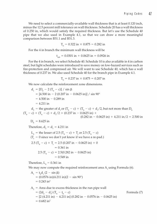
P i p i n g C o d e s 47
We need to select a commercially-available wall thickness that is at least 0.120 inch, minus the 12.5 percent mill tolerance on wall thickness. Schedule 20 has a wall thickness of 0.250 in, which would satisfy the required thickness. But let’s use the Schedule 40 pipe that we also used in Example 4.1, so that we can draw a more meaningful comparison between B31.1 and B31.3.
Th � 0.322 in � 0.875 � 0.282 in
For the 4 in branch the minimum wall thickness will be
tmb � 0.0301 in � 0.0625 in � 0.0926 in
For the 4 in branch, we select Schedule 40. Schedule 10 is also available in 4 in carbon steel, but light schedules were introduced to save money on low-hazard services such as fire-protection and compressed air. We will want to use Schedule 40, which has a wall thickness of 0.237 in. We also used Schedule 40 for the branch pipe in Example 4.1.
Tb � 0.237 in � 0.875 � 0.207 in
We now calculate the reinforcement zone dimensions.
d1 � [Db � 2 (Tb � c)] / sin
� [4.500 in � 2 (0.207 in � 0.0625 in)] / sin 90°
� 4.500 in � 0.289 in
� 4.211 in
d2 � the greater of d1 or (Tb � c) � (Th � c) � d1/2, but not more than Dh
(Tb � c) � (Th � c) � d1/2 � (0.237 in � 0.0625 in) �(0.282 in � 0.0625 in) � 4.211 in/2 � 2.500 in
Dh � 8.625 in
Therefore, d2 � d1 � 4.211 in
L4 � the lesser of 2.5 (Tb � c) � Tr or 2.5 (Th � c) (Tr � 0 since we don’t yet know if we have a re-pad.)
2.5 (Tb � c) � Tr � 2.5 (0.207 in � 0.0625 in) � 0
� 0.361 in
2.5 (Th � c) � 2.5(0.282 in � 0.0625 in)
� 0.549 in
Therefore, L4 � 0.361 in
We may now compute the required reinforcement area A1 using Formula (6).
A1 � thd1 (2 � sin ) � (0.0576 in)(4.211 in)(2 � sin 90°) � 0.243 in2
A2 � Area due to excess thickness in the run pipe wall � (2d2 � d1) (Th � th
� c) Formula (7) � [2 (4.211 in) � 4.211 in] (0.282 in � 0.0576 in � 0.0625 in) � 0.682 in2
48 C h a p t e r 4
We note that we can stop here, since the area due to excess pipe wall in the run exceeds the required reinforcement area. Comparing the results of B31.1 with B31.3, we see that:
Description B31.1 B31.3
Required Reinforcement Area 0.284 in2 0.243 in2
Area due to Excess Thickness in Run Pipe Wall
0.600 in2 0.682 in2
Allowable Stress SE = 10,050 psi SE = 12,300 psi
These were the identical pipe configurations and materials. We eventually arrived at the same result, that is, no additional material such as a re-pad was required. But notice the difference in the values calculated between the two codes.9
Let’s re-work the same problem with the design parameters given in Example 4.2.
Example 4.5Given: Design Pressure: 1000 psigTemperature: 675°FService: Superheated Steam inside a powerhouseMaterial: A53 Grade A, ERW (electric resistance welded) pipe.Code: ASME B31.3Design: A fabricated 4 in branch connection at 90°, coming off an 8 in diameter header.
Solution:By Formula (3a):
th � (1000 psi)(8.625 in) /2[(14,450 psi)(0.85)(1.0) � (1000 psi)(0.4)] � 0.340 in tb � (1000 psi)(4.500 in) / 2[(14,450 psi)(0.85)(1.0) � (1000 psi)(0.4)] � 0.177 in
Let c � 0.0625 in
tmh � th � c � 0.340 in � 0.0625 in � 0.403in
We select Schedule 80, with a wall thickness of 0.500 in. The actual minimum wall thickness of 8 in diameter Schedule 80 pipe, less the mill tolerance is
Th � 0.500 in � 0.875 � 0.438 in
For the 4 in branch the minimum wall thickness will be
tmb � 0.177 in � 0.0625 in � 0.240 in
For the 4 in branch, we select Schedule 80, with a wall thickness of 0.337 in.
Tb � 0.337 in � 0.875 � 0.295 in
We now calculate the reinforcement zone dimensions.
9 Note also that for a superheated steam line as described, the appropriate code application would be ASME B31.1. The B31.3 example is provided for instruction only.
P i p i n g C o d e s 49
d1 � [Db � 2(Tb � c)] / sin � [4.500 in � 2(0.295 in � 0.0625 in)] / sin 90° � 4.500 in � 0.465 in � 4.035 in
d2 � the greater of d1 or (Tb � c) � (Th � c) � d1/2, but not more than Dh
(Tb � c) � (Th � c) � d1/2 � (0.295 in � 0.0625 in) �(0.438 in � 0.0625 in) � 4.035 in/2 � 2.626 in
Dh � 8.625 inTherefore, d2 � d1 � 4.035 in
L4 � the lesser of 2.5(Tb � c) � Tr or 2.5(Th � c) (Tr � 0 since we don’t yet know if we have a re-pad)
2.5 (Tb � c) � Tr � 2.5(0.295 in � 0.0625 in) � 0 � 0.581 in
OR
2.5 (Th � c) � 2.5(0.438 in � 0.0625 in) � 0.939 in
Therefore, L4 � 0.581 inWe may now compute the required reinforcement area A1 using Formula (6).
A1 � thd1 (2 � sin ) � (0.340 in)(4.035 in)(2 � sin 90°) � 1.372 in2
A2 � Area due to excess thickness in the run pipe wall � (2d2 � d1) (Th � th
� c) Formula (7) � [2 (4.035 in) � 4.035 in] (0.438 in � 0.340 in � 0.0625 in) � 0.143 in2
A3 � Area due to excess thickness in the branch pipe wall � 2L4 (Tb � tb � c) / sin Formula (8) � 2 (0.581 in)(0.295 in � 0.177 in � 0.0625 in) / sin 90° � 0.065 in2
A4 � Area provided by welds and attached reinforcements
Let’s assume that the welds are 5/16 in per leg. The weld area will be:
A4 (weld) � 2 (1/2)(0.3125 in)(0.3125 in) � 0.098 in2
The factor “2” is because we have the same fillet weld triangle on both sides of the branch. We still have a deficit of reinforcing material of:
1.372 in2 � 0.143 in2 � 0.065 in2 � 0.098 in2 � 1.066 in2
50 C h a p t e r 4
We need a re-pad. B31.3 does not mention the aspect ratio of 4:1 that B31.1 recommends. But we can still use it, provided it does not lay outside the reinforcement zone. The half-width of the reinforcement zone is d2 � 4.035 in. The OD of the branch pipe is 4.500 in. Again we want the branch fillet welded to the run before the repad is applied, so the minimum ID of the repad is
4.5 in � 2(5/16 in) � 5.125 inThis leaves us with
4.035 in � 5.125 in/2 � 1.473 in as the limit for the width of a re-pad.
We select a thickness approximately one-fourth of the width. If we use a 3/8 in plate by 11⁄4 in wide, then
A4(re-pad) � 2 � 0.375 in � 1.25 in � 0.9375 in2
In practice, the 5/16 in annulus between the ID of the repad and the OD of the branch pipe will be filled with weld to the height of the repad, so this adds to the available metal within the reinforcement zone
A4(weld) � 2(3/8 in)(5/16 in) � .098 in2 � 0.332 in2
The additional metal added by the repad and weld is
A4 � 0.9375 in2 � 0.332 in2 � 1.26 in2
and the required reinforcement area is satisfied.
Note that we must choose a re-pad material that is compatible with the metallurgy of the adjoining pipes. Also, if the allowable stress of the re-pad is less than that of the run pipe, its area must be increased in proportion to the ratio of the allowable stress of the run pipe over the re-pad. If the re-pad allowable stress is more than the allowable stress of the run pipe, no credit may be taken.
Comparing the results of this example to Example 4.2, we see that we were able to use a Schedule 80 header for B31.3 instead of a Schedule 100 header for B31.1.
305.2 Specific RequirementsThis section describes what piping may be used for certain services. A review of the four fluid services reveals that the most benign service is Category D, followed by normal fluids , and then perhaps high pressure fluids with Category M fluids constituting the most hazardous service. If you were dealing with water in a plant it would most likely be a Category D fluid service, regardless of whether it is potable or cooling water or general service water. Most water service in a manufacturing facility does not exceed 150 psig or 366°F.
Paragraph 305.2.1 specifies that there are three pipe specifications that are suitable only for these benign Category D services. They are:
• API 5L, Furnace Butt-Welded
• ASTM A53, Type F (also Furnace Butt-Welded)
• ASTM A 134 if made from other than ASTM A285 plate
These pipes are not suitable for the more hazardous services of B31.3. The furnace butt-weld pipes have a Weld Joint Quality Factor Ej of only 0.6. These pipes are made with a continuous longitudinal butt weld. The furnace butt weld process is a continuous
P i p i n g C o d e s 51
forge weld that is made through the application of mechanical pressure. It is not as strong as electric resistance welded pipe, electric fusion welded pipe, or seamless pipe.
Paragraph 305.2.2 discusses pipe that requires safeguarding . The two pipe spec i-fications that require safeguarding for services other than Category D are:
• ASTM A 134 if made from ASTM A285 plate• ASTM A139.
Because safeguarding is an added expense in terms of both design and installation, the designer would be better off using a more suitable pipe material. But this avoids the concept of safeguarding altogether, which may be required in other circumstances.
For example, suppose you are faced with designing a piping system that handles dilute hydrochloric acid. You realize that it is corrosive to carbon steel, and stainless steel is not suitable due to the possibility of stress corrosion cracking. You select a PVC piping system that is impervious to the HCl, but might not hold up so well against fork truck traffic. The pipe system must be “safeguarded.”
ASME B31.3 Appendix G addresses the concept of safeguarding . Safeguarding is the provision of protective measures to minimize the risk of accidental damage to a piping system, or to mitigate the consequences of a possible pipe failure. Such provisions include, but are not limited to:
• Physical barriers• Guards around pipe flanges to prevent spraying of fluids if a gasket fails• Isolation of hazardous areas• Installation of fire protection systems• Process controls to shut down systems in the event of a failure• Grounding of static charges to prevent ignition of flammable vapors• Implementation of special operating or maintenance procedures.
These are considerations that are often addressed in a HAZOP analysis.Paragraph 305.2.3 lists piping that may be used under severe cyclic conditions.
Severe cyclic conditions are defined in Paragraph 300.2 as those in which the number of cycles exceeds 7000, and the Displacement Stress Range (SE) exceeds the 80 percent of the Allowable Displacement Stress Range (SA).
As in ASME B31.1, the cycles referred to in this section of B31.3 are temperature cycles and not pressure cycles.
The allowable displacement stress (SA) is dependent only on the material, the temperature fluctuations during the operating cycles, and the number of cycles.
The Displacement Stress Range (SE) is dependent only on the loading conditions and the pipe geometry.
The calculation of the resultant stresses is best left to a computer program, as it becomes cumbersome. For the moment, it is enough to realize that severe cyclic conditions are not common, since thermal cycles above 7000 over the expected life of the system are not common.
319.4 Flexibility AnalysisLike B31.1, there is a simple test to determine if a more complex stress analysis is required. The prerequisites are the same as for B31.1, but the equation is slightly
52 C h a p t e r 4
different, using the outside diameter rather than the nominal diameter. The threshold values are different as well.
Dy/(L � U)2 � K1 (Formula 16) in the code
where
K1 � 30 SA/Ea (in/ft)2
= 208,000 SA/Ea (mm/m)2
SA � Allowable Displacement Stress [ksi or MPa]
Ea � Modulus of Elasticity at 70°F [ksi or MPa]
f � may be as high as 1.2 for some ferrous materials.
D � Outside diameter of the pipe[in or mm]
Example 4.6Using the same system as Example 4.3, determine if a more complex analysis is required using Formula 16.Solution: The left hand side of the equation would appear to be identical to the left hand side of the equation we used for B31.1 in Example 4.3. Interestingly, or perhaps oddly, ASME B31.3 uses a different Coefficient of Thermal Expansion than we found in B31.1. This may affect the thermal displacements.
� � 6.49 � 10-6 in/in/°F from ASME B31.3 Table C-3
x � �Lx(T) � (6.49 � 10-6 in/in/°F)(8 ft � 12 in/ft)(180°F) � 0.11 in
y � �Ly(T) � (6.49 � 10-6 in/in/°F)(4 ft � 12 in/ft)(180°F) � 0.06 in
z � �Ly(T) � (6.49 � 10-6 in/in/°F)(6 ft � 12 in/ft)(180°F) � 0.08 in
y � (x2 � y2 � z2)½ � [(0.11 in)2 � (0.06 in)2 � (0.08 in)2]½ � 0.15 in
U � 10.8 ft and L � 18 ft as before. Dy/(L � U)2 � (6.625)(0.15)/(18 � 10.8)2 � 0.019
SA � f (1.25 Sc � 0.25 Sh)
f � 1.07 this time, since the upper limit is 1.2.
Sc � Sh � 20.0 ksi from ASME B31.3 Table A-1
SA � (1.07)[(1.25)(20.0 ksi) � (0.25)(20.0 ksi)] � 32,100 psi
Ea � 29.5 � 106 psi from ASME Table C-6
K1 � 30(32,100 psi/29.5 � 106 psi) � 0.032
Then Dy/(L � U)2 � 0.019 � 0.032 and the system again does not require a more complex analysis, other than to determine if the loads applied at the anchors are excessive.
345 TestingB31.3 requires that all piping designed in accordance with B31.3 be leak tested. For the benign Category D fluids, a service test may be conducted using the service fluid as the test medium, and setting the test pressure at the operating pressure. This is in lieu of conducting a hydrostatic test. Of course, a hydrostatic test may be applied at the Owner’s discretion. It is not required however.

P i p i n g C o d e s 53
The B31.3 hydrostatic test is similar to that described in B31.1. It is most often conducted with clean water, unless that would pose a problem such as contamination or corrosion, and it is held for 10 minutes at 1.5 times the design pressure.
Due to the possibility of brittle fracture of nonmetallic piping which may be found in systems under the scope of B31.3, a pneumatic leak test requires a pressure relief device having a set pressure of the test pressure plus the smaller of 50 psi or 10 percent of the test pressure.
Because chemical piping can involve core complicated equipment and piping designs, there may be additional factors to be considered in a pressure test.
Internal piping of a jacketed line should be tested at the more critical of either the internal or jacket design pressure (Paragraph 345.2.5).
Because there may be elevated temperatures, Paragraph 345.4.2 includes a provision for establishing a more appropriate test pressure:
PT � 1.5 P (ST/S) Equation (24) in the code
and ST/S � 6.5where
PT � Minimum test gage pressure
P � Internal design gage pressure
ST � Stress value at test temperature
S � Stress value at design temperature as listed in Table A-1.
For high pressure piping (pressures in excess of the Class 2500 rating for the design temperature and material group), the limit of ST/S < 6.5 does not apply. Further, the allowable stresses are taken from Table K-1 rather than from Table A-1. (Paragraph K345.4.2)
ASME B31.9 Building Services PipingThe scope of this code envelopes industrial, institutional, commercial, public
buildings, and multi-unit residences. Because the most demanding service that one might encounter in such a facility would be steam and condensate, one might expect this code to rely on ASME B31.1. In fact, there are many similarities between B31.9 and B31.1.
Both codes cover boiler external piping . However, B31.9 includes steam boilers up to 15 psig maximum, while B31.1 uses 15 psig as a lower limit of its scope. Similarly, B31.9 includes water heating units up to 160 psig maximum, while B31.1 uses 160 psig as its lower limit for hot water.
904 Pressure Design of ComponentsB31.9 permits pressure and wall thickness calculations to be performed in accordance with B31.1. Alternately, it permits these to be calculated using the following formulas:
tm � (PD/2SE) � A (Formula 1)
P � 2SE (tm � A)/D (Formula 2)
where the variables are defined as in ASME B31.1. As with B31.1, the Maximum Allowable Stress Values tabulated in Table A-1 already include the weld joint efficiency factor E. That is, the values tabulated are equal to SE.
54 C h a p t e r 4
Branch connection strength follows ASME B31.1.Minimum flexibility is similar to the older version of the ASME B31.1 flexibility
analysis, i.e.
DY/(L-U)2 � 0.03 for Imperial units, orDY/(L-U)2 � 208.3 for metric units
Under B31.9:
• No cast iron fittings are permitted• No more than two anchors and no intermediate restraints are present
(same as B31.1)• Two different pipe sizes may be used, but they may differ by only one size • The least wall thickness is at least 75 percent of the greatest wall thickness.
These flexibility criteria are always to be applied with great care, and are invalid for unequal leg U-bends in which L/U � 2.5. Further, just because the system appears to satisfy the flexibility criterion, there is no assurance that the reactions at the anchors will be acceptable.
Summary of Code ComparisonsAllowable stress values for the most common metal piping at temperatures up to 100°F:
B31.1: 1/4 of the specified minimum tensile strengthB31.3: 1/3 of the specified minimum tensile strengthB31.9: 1/4 of the specified minimum tensile strength
Tabulated stress values shown in the “A” tables:B31.1: Includes Quality Factor E or FB31.3: Does NOT include Quality Factor. See B31.3 Tables A-1A or A-1BB31.9: Includes Quality Factor E or F
Minimum required wall thickness:B31.1: tm � [(PDo) / 2(SE � Py)] � A Formula (3)B31.3: tm � PD/2(SEW � PY) � c Formula (2) and Formula (3a)B31.9: tm � PD/2SE � A Formula (1)
Internal design pressure:B31.1: P � [2SE(tm � A)] / [Do � 2y(tm � A)] Formula (4)B31.3: P � 2(SEW � PY) (tm –c) / DoB31.9: P � 2SE(tm – A) / Do Formula (2)
Minimum flexibility analysis:
The system is identical to a successfully operating installation or replaces one with a satisfactory service record, or satisfies the following:
B31.1: DY/(L-U)2 � 30 SA/EC for Imperial units orDY/(L-U)2 � 208,000 SA/EC for metric units
B31.3: Virtually identical to B31.1, but there may be some slight variations in material values.
B31.9: DY/(L-U)2 � 0.03 for Imperial units (Formula 9)
55
CHAPTER 5Specifications and Standards
Starting with a blank sheet of paper can be either intimidating or liberating. Very often in a project the piping specifications are available in some form or another. They may be specific to the current project or left over from an earlier project but deemed to be suitable for the one you are working on. Most engineers collect specifications as they move from project to project. These specs tend to evolve over time, with appendages growing out of them to handle a situation that stung some poor engineer once upon a time. One danger in recycling old specifications is that they often refer to out-of-date or obsolete specifications and standards.
Whereas codes which are adopted by regulating authorities are required to be met or exceeded, specifications and standards are not necessarily mandatory requirements of regulating authorities, although they are often cited within
the codes.Standards are prepared by trade associations to provide guidance on how materials,
equipment, or systems should be installed or operated. An example of this is the Compressed Gas Association, which offers technical advice such as CGA G-4 Oxygen . This standard provides design considerations that assist in the safe operation of oxygen piping systems. Some standards set dimensions for fittings, so that every time you need to connect one 150 lb 6 in flange to another 150 lb 6 in flange, the bolt holes line up and the raised faces of the flanges mirror each other on the opposite sides of the gasket. This should be true even if the flanges are made by different manufacturers.
Specifications can mean either those that are project-specific, or those that are developed to establish the requirements of a material like carbon steel or a type of pipe like A-53 Grade B, or a valve.
Project-specific specifications are those that are prepared by the engineer to describe the quality of the material and workmanship for a project. They may take the form of an outlined narrative or a table. Project-specific specifications will be discussed in a later chapter.
The other type of specification is most often developed by a standards organization, government agency, or trade association. See Table 5.1. When we speak of “specifications” in this chapter, this is the type of specification that we mean.
56 C h a p t e r 5
The codes, standards, and specifications are usually identified using the following convention:
ACRO SPEC-YR
Where
ACRO � the acronym of the organization which has developed the code, standard, or specification
SPEC � an alphanumeric identifier
YR � the year of the latest revision
The codes, standards, or specifications are updated in regular intervals so that the latest technology is available, and so it is important to know which revision is the latest. In this book, we will omit the revision year since it will be sufficient to identify the document.
A list of some of the common codes, standards, and specifications appears in Table 5.2. While this list is not meant to be exhaustive, it represents a practical collection of applicable references in one place. The engineer may search for available references using this table.
Note that some of the standards share joint responsibility between two organizations. This occurs frequently between ASME and ANSI, and a good example is one of the codes for flanges from NPS ½ to NPS 24. The standard is ASME/ANSI B16.5. This is often referred to as ANSI B16.5, and the convention in this book will be to use the organization that is more commonly identified with the standard. If the reader were to look for the standard, it would be easy to locate using only the one organization. But when the standard is located in a library, or on-line, it will be identified as ASME/ANSI B16.5.
For piping and fittings, it is often necessary to identify both the material specification and a specification that addresses the dimensional requirements of the component.
The presence of an asterisk next to a specification listed in Table 5.2 indicates that the specification is also listed in ASME B31.1 Table 126.1. Table 126.1 is important because it identifies “standard” piping components, which are suitable for use at temperature-pressure ratings specified by the manufacturing standard.
Table 5.3 lists the various ASME stamps required by the ASME codes.
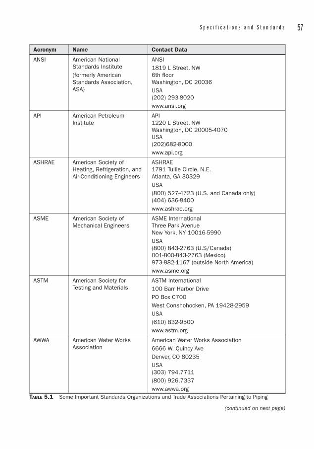
S p e c i f i c a t i o n s a n d S t a n d a r d s 57
Acronym Name Contact Data
ANSI American National Standards Institute(formerly American Standards Association, ASA)
ANSI1819 L Street, NW6th floorWashington, DC 20036USA(202) 293-8020www.ansi.org
API American Petroleum Institute
API1220 L Street, NWWashington, DC 20005-4070USA(202)682-8000www.api.org
ASHRAE American Society of Heating, Refrigeration, and Air-Conditioning Engineers
ASHRAE1791 Tullie Circle, N.E.Atlanta, GA 30329USA(800) 527-4723 (U.S. and Canada only) (404) 636-8400www.ashrae.org
ASME American Society of Mechanical Engineers
ASME InternationalThree Park AvenueNew York, NY 10016-5990USA(800) 843-2763 (U.S/Canada)001-800-843-2763 (Mexico)973-882-1167 (outside North America)www.asme.org
ASTM American Society for Testing and Materials
ASTM International100 Barr Harbor Drive PO Box C700West Conshohocken, PA 19428-2959USA(610) 832-9500www.astm.org
AWWA American Water Works Association
American Water Works Association 6666 W. Quincy AveDenver, CO 80235USA(303) 794.7711 (800) 926.7337www.awwa.org
TABLE 5.1 Some Important Standards Organizations and Trade Associations Pertaining to Piping
(continued on next page)
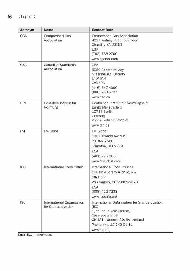
58 C h a p t e r 5
Acronym Name Contact Data
CGA Compressed Gas Association
Compressed Gas Association4221 Walney Road, 5th FloorChantilly, VA 20151USA(703) 788-2700www.cganet.com
CSA Canadian Standards Association
CSA5060 Spectrum WayMississauga, OntarioL4W 5N6CANADA(416) 747-4000(800) 463-6727www.csa.ca
DIN Deutches Institut für Normung
Deutsches Institut für Normung e. V.Burggrafenstraße 610787 BerlinGermanyPhone: +49 30 2601-0www.din.de
FM FM Global FM Global1301 Atwood Avenue P.O. Box 7500 Johnston, RI 02919 USA(401) 275 3000www.fmglobal.com
ICC International Code Council International Code Council500 New Jersey Avenue, NW 6th FloorWashington, DC 20001-2070USA(888) 422-7233www.iccsafe.org
ISO International Organization for Standardization
International Organization for Standardization (ISO)1, ch. de la Voie-Creuse, Case postale 56CH-1211 Geneva 20, SwitzerlandPhone +41 22 749 01 11www.iso.org
TABLE 5.1 (continued)
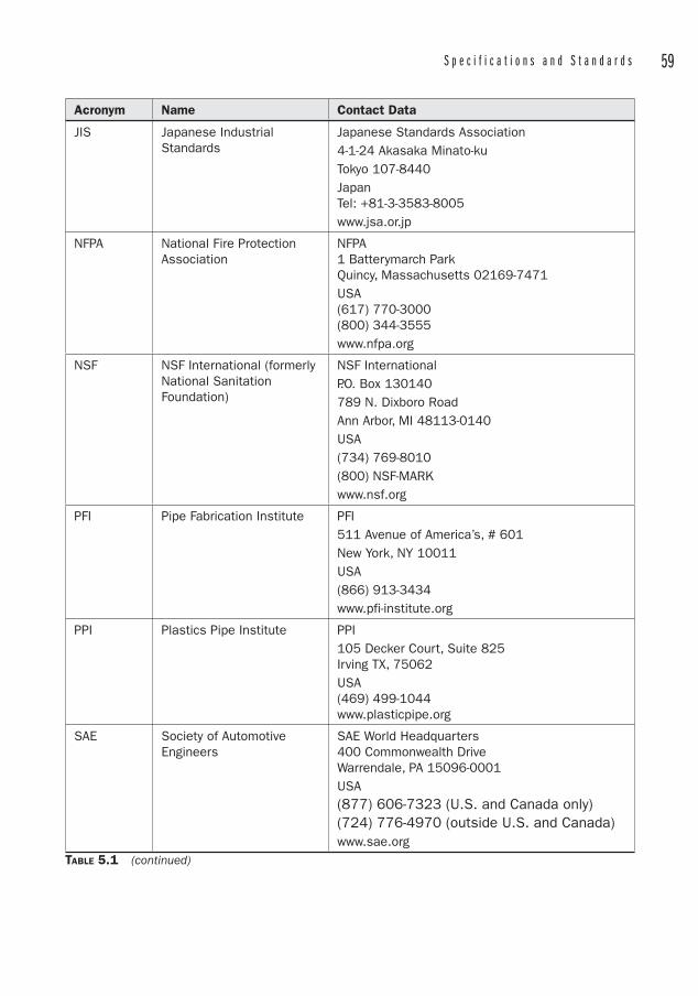
S p e c i f i c a t i o n s a n d S t a n d a r d s 59
Acronym Name Contact Data
JIS Japanese Industrial Standards
Japanese Standards Association4-1-24 Akasaka Minato-kuTokyo 107-8440 JapanTel: +81-3-3583-8005www.jsa.or.jp
NFPA National Fire Protection Association
NFPA1 Batterymarch ParkQuincy, Massachusetts 02169-7471USA(617) 770-3000(800) 344-3555www.nfpa.org
NSF NSF International (formerly National Sanitation Foundation)
NSF InternationalP.O. Box 130140789 N. Dixboro RoadAnn Arbor, MI 48113-0140USA(734) 769-8010(800) NSF-MARKwww.nsf.org
PFI Pipe Fabrication Institute PFI511 Avenue of America’s, # 601 New York, NY 10011 USA(866) 913-3434 www.pfi-institute.org
PPI Plastics Pipe Institute PPI105 Decker Court, Suite 825 Irving TX, 75062 USA(469) 499-1044 www.plasticpipe.org
SAE Society of Automotive Engineers
SAE World Headquarters 400 Commonwealth DriveWarrendale, PA 15096-0001 USA(877) 606-7323 (U.S. and Canada only) (724) 776-4970 (outside U.S. and Canada)www.sae.org
TABLE 5.1 (continued)
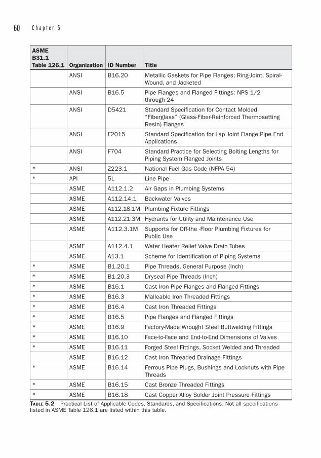
60 C h a p t e r 5
ASMEB31.1Table 126.1 Organization ID Number Title
ANSI B16.20 Metallic Gaskets for Pipe Flanges; Ring-Joint, Spiral-Wound, and Jacketed
ANSI B16.5 Pipe Flanges and Flanged Fittings: NPS 1/2 through 24
ANSI D5421 Standard Specification for Contact Molded “Fiberglass” (Glass-Fiber-Reinforced Thermosetting Resin) Flanges
ANSI F2015 Standard Specification for Lap Joint Flange Pipe End Applications
ANSI F704 Standard Practice for Selecting Bolting Lengths for Piping System Flanged Joints
* ANSI Z223.1 National Fuel Gas Code (NFPA 54)
* API 5L Line Pipe
ASME A112.1.2 Air Gaps in Plumbing Systems
ASME A112.14.1 Backwater Valves
ASME A112.18.1M Plumbing Fixture Fittings
ASME A112.21.3M Hydrants for Utility and Maintenance Use
ASME A112.3.1M Supports for Off-the -Floor Plumbing Fixtures for Public Use
ASME A112.4.1 Water Heater Relief Valve Drain Tubes
ASME A13.1 Scheme for Identification of Piping Systems
* ASME B1.20.1 Pipe Threads, General Purpose (Inch)
* ASME B1.20.3 Dryseal Pipe Threads (Inch)
* ASME B16.1 Cast Iron Pipe Flanges and Flanged Fittings
* ASME B16.3 Malleable Iron Threaded Fittings
* ASME B16.4 Cast Iron Threaded Fittings
* ASME B16.5 Pipe Flanges and Flanged Fittings
* ASME B16.9 Factory-Made Wrought Steel Buttwelding Fittings
* ASME B16.10 Face-to-Face and End-to-End Dimensions of Valves
* ASME B16.11 Forged Steel Fittings, Socket Welded and Threaded
ASME B16.12 Cast Iron Threaded Drainage Fittings
* ASME B16.14 Ferrous Pipe Plugs, Bushings and Locknuts with Pipe Threads
* ASME B16.15 Cast Bronze Threaded Fittings
* ASME B16.18 Cast Copper Alloy Solder Joint Pressure FittingsTABLE 5.2 Practical List of Applicable Codes, Standards, and Specifications. Not all specifications listed in ASME Table 126.1 are listed within this table.
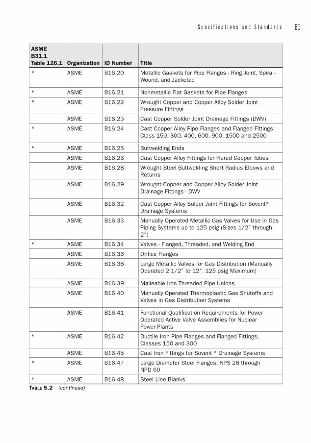
S p e c i f i c a t i o n s a n d S t a n d a r d s 61
ASMEB31.1Table 126.1 Organization ID Number Title
* ASME B16.20 Metallic Gaskets for Pipe Flanges - Ring Joint, Spiral-Wound, and Jacketed
* ASME B16.21 Nonmetallic Flat Gaskets for Pipe Flanges
* ASME B16.22 Wrought Copper and Copper Alloy Solder Joint Pressure Fittings
ASME B16.23 Cast Copper Solder Joint Drainage Fittings (DWV)
* ASME B16.24 Cast Copper Alloy Pipe Flanges and Flanged Fittings: Class 150, 300, 400, 600, 900, 1500 and 2500
* ASME B16.25 Buttwelding Ends
ASME B16.26 Cast Copper Alloy Fittings for Flared Copper Tubes
ASME B16.28 Wrought Steel Buttwelding Short Radius Elbows and Returns
ASME B16.29 Wrought Copper and Copper Alloy Solder Joint Drainage Fittings - DWV
ASME B16.32 Cast Copper Alloy Solder Joint Fittings for Sovent® Drainage Systems
ASME B16.33 Manually Operated Metallic Gas Valves for Use in Gas Piping Systems up to 125 psig (Sizes 1/2” through 2”)
* ASME B16.34 Valves - Flanged, Threaded, and Welding End
ASME B16.36 Orifice Flanges
ASME B16.38 Large Metallic Valves for Gas Distribution (Manually Operated 2 1/2” to 12”, 125 psig Maximum)
ASME B16.39 Malleable Iron Threaded Pipe Unions
ASME B16.40 Manually Operated Thermoplastic Gas Shutoffs and Valves in Gas Distribution Systems
ASME B16.41 Functional Qualification Requirements for Power Operated Active Valve Assemblies for Nuclear Power Plants
* ASME B16.42 Ductile Iron Pipe Flanges and Flanged Fittings, Classes 150 and 300
ASME B16.45 Cast Iron Fittings for Sovent ® Drainage Systems
* ASME B16.47 Large Diameter Steel Flanges: NPS 26 through NPD 60
* ASME B16.48 Steel Line BlanksTABLE 5.2 (continued)
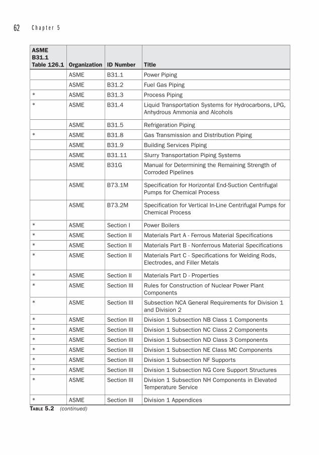
62 C h a p t e r 5
ASMEB31.1Table 126.1 Organization ID Number Title
ASME B31.1 Power Piping
ASME B31.2 Fuel Gas Piping
* ASME B31.3 Process Piping
* ASME B31.4 Liquid Transportation Systems for Hydrocarbons, LPG, Anhydrous Ammonia and Alcohols
ASME B31.5 Refrigeration Piping
* ASME B31.8 Gas Transmission and Distribution Piping
ASME B31.9 Building Services Piping
ASME B31.11 Slurry Transportation Piping Systems
ASME B31G Manual for Determining the Remaining Strength of Corroded Pipelines
ASME B73.1M Specification for Horizontal End-Suction Centrifugal Pumps for Chemical Process
ASME B73.2M Specification for Vertical In-Line Centrifugal Pumps for Chemical Process
* ASME Section I Power Boilers
* ASME Section II Materials Part A - Ferrous Material Specifications
* ASME Section II Materials Part B - Nonferrous Material Specifications
* ASME Section II Materials Part C - Specifications for Welding Rods, Electrodes, and Filler Metals
* ASME Section II Materials Part D - Properties
* ASME Section III Rules for Construction of Nuclear Power Plant Components
* ASME Section III Subsection NCA General Requirements for Division 1 and Division 2
* ASME Section III Division 1 Subsection NB Class 1 Components
* ASME Section III Division 1 Subsection NC Class 2 Components
* ASME Section III Division 1 Subsection ND Class 3 Components
* ASME Section III Division 1 Subsection NE Class MC Components
* ASME Section III Division 1 Subsection NF Supports
* ASME Section III Division 1 Subsection NG Core Support Structures
* ASME Section III Division 1 Subsection NH Components in Elevated Temperature Service
* ASME Section III Division 1 AppendicesTABLE 5.2 (continued)
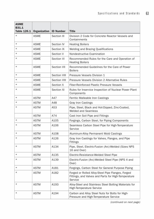
S p e c i f i c a t i o n s a n d S t a n d a r d s 63
ASMEB31.1Table 126.1 Organization ID Number Title
* ASME Section III Division 2 Code for Concrete Reactor Vessels and Containments
* ASME Section IV Heating Boilers
* ASME Section IX Welding and Brazing Qualifications
* ASME Section V Nondestructive Examination
* ASME Section VI Recommended Rules for the Care and Operation of Heating Boilers
* ASME Section VII Recommended Guidelines for the Care of Power Boilers
* ASME Section VIII Pressure Vessels Division 1
* ASME Section VIII Pressure Vessels Division 2 Alternative Rules
* ASME Section X Fiber-Reinforced Plastic Pressure Vessels
* ASME Section XI Rules for Inservice Inspection of Nuclear Power Plant Components
* ASTM A47 Ferritic Malleable Iron Castings
* ASTM A48 Gray Iron Castings
* ASTM A53 Pipe, Steel, Black and Hot-Dipped, Zinc-Coated, Welded and Seamless
ASTM A74 Cast Iron Soil Pipe and Fittings
* ASTM A105 Forgings, Carbon Steel, for Piping Components
* ASTM A106 Seamless Carbon Steel Pipe for High-Temperature Service
* ASTM A108 Aluminum-Alloy Permanent Mold Castings
* ASTM A126 Gray Iron Castings for Valves, Flanges, and Pipe Fittings
* ASTM A134 Pipe, Steel, Electric-Fusion (Arc)-Welded (Sizes NPS 16 and Over)
* ASTM A135 Electric-Resistance-Welded Steel Pipe
* ASTM A139 Electric-Fusion (Arc)-Welded Steel Pipe (NPS 4 and Over)
* ASTM A181 Forgings, Carbon Steel for General Purpose Piping
* ASTM A182 Forged or Rolled Alloy-Steel Pipe Flanges, Forged Fittings, and Valves and Parts for High-Temperature Service
* ASTM A193 Alloy-Steel and Stainless Steel Bolting Materials for High-Temperature Service
* ASTM A194 Carbon and Alloy Steel Nuts for Bolts for High-Pressure and High-Temperature Service
(continued on next page)
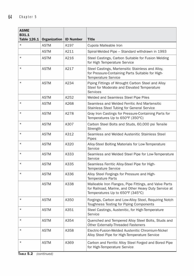
64 C h a p t e r 5
ASMEB31.1Table 126.1 Organization ID Number Title
* ASTM A197 Cupola Malleable Iron
ASTM A211 Spiral-Welded Pipe – Standard withdrawn in 1993
* ASTM A216 Steel Castings, Carbon Suitable for Fusion Welding for High Temperature Service
* ASTM A217 Steel Castings, Martensitic Stainless and Alloy, for Pressure-Containing Parts Suitable for High-Temperature Service
* ASTM A234 Piping Fittings of Wrought Carbon Steel and Alloy Steel for Moderate and Elevated Temperature Services
ASTM A252 Welded and Seamless Steel Pipe Piles
* ASTM A268 Seamless and Welded Ferritic And Martensitic Stainless Steel Tubing for General Service
* ASTM A278 Gray Iron Castings for Pressure-Containing Parts for Temperatures Up to 650°F (350°C)
* ASTM A307 Carbon Steel Bolts and Studs, 60,000 psi Tensile Strength
* ASTM A312 Seamless and Welded Austenitic Stainless Steel Pipes
* ASTM A320 Alloy-Steel Bolting Materials for Low-Temperature Service
* ASTM A333 Seamless and Welded Steel Pipe for Low-Temperature Service
* ASTM A335 Seamless Ferritic Alloy-Steel Pipe for High-Temperature Service
* ASTM A336 Alloy Steel Forgings for Pressure and High-Temperature Parts
ASTM A338 Malleable Iron Flanges, Pipe Fittings, and Valve Parts for Railroad, Marine, and Other Heavy Duty Service at Temperatures Up to 650°F (345°C)
* ASTM A350 Forgings, Carbon and Low-Alloy Steel, Requiring Notch Toughness Testing for Piping Components
* ASTM A351 Steel Castings, Austenitic, for High-Temperature Service
* ASTM A354 Quenched and Tempered Alloy Steel Bolts, Studs and Other Externally-Threaded Fasteners
* ASTM A358 Electric-Fusion-Welded Austenitic Chromium-Nickel Alloy Steel Pipe for High-Temperature Service
* ASTM A369 Carbon and Ferritic Alloy Steel Forged and Bored Pipe for High-Temperature Service
TABLE 5.2 (continued)
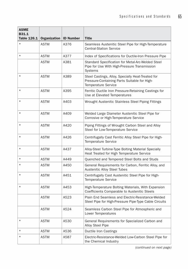
S p e c i f i c a t i o n s a n d S t a n d a r d s 65
ASMEB31.1Table 126.1 Organization ID Number Title
* ASTM A376 Seamless Austenitic Steel Pipe for High-Temperature Central-Station Service
* ASTM A377 Index of Specifications for Ductile-Iron Pressure Pipe
ASTM A381 Standard Specification for Metal-Arc-Welded Steel Pipe for Use With High-Pressure Transmission Systems
* ASTM A389 Steel Castings, Alloy, Specially Heat-Treated for Pressure-Containing Parts Suitable for High-Temperature Service
* ASTM A395 Ferritic Ductile Iron Pressure-Retaining Castings for Use at Elevated Temperatures
* ASTM A403 Wrought Austenitic Stainless Steel Piping Fittings
* ASTM A409 Welded Large Diameter Austenitic Steel Pipe for Corrosive or High-Temperature Service
* ASTM A420 Piping Fittings of Wrought Carbon Steel and Alloy Steel for Low-Temperature Service
* ASTM A426 Centrifugally Cast Ferritic Alloy Steel Pipe for High-Temperature Service
* ASTM A437 Alloy-Steel Turbine-Type Bolting Material Specially Heat Treated for High Temperature Service
* ASTM A449 Quenched and Tempered Steel Bolts and Studs
* ASTM A450 General Requirements for Carbon, Ferritic Alloy, and Austenitic Alloy Steel Tubes
* ASTM A451 Centrifugally Cast Austenitic Steel Pipe for High-Temperature Service
* ASTM A453 High-Temperature Bolting Materials, With Expansion Coefficients Comparable to Austenitic Steels
ASTM A523 Plain End Seamless and Electric-Resistance-Welded Steel Pipe for High-Pressure Pipe-Type Cable Circuits
ASTM A524 Seamless Carbon Steel Pipe for Atmospheric and Lower Temperatures
* ASTM A530 General Requirements for Specialized Carbon and Alloy Steel Pipe
* ASTM A536 Ductile Iron Castings
* ASTM A587 Electric-Resistance-Welded Low-Carbon Steel Pipe for the Chemical Industry
(continued on next page)
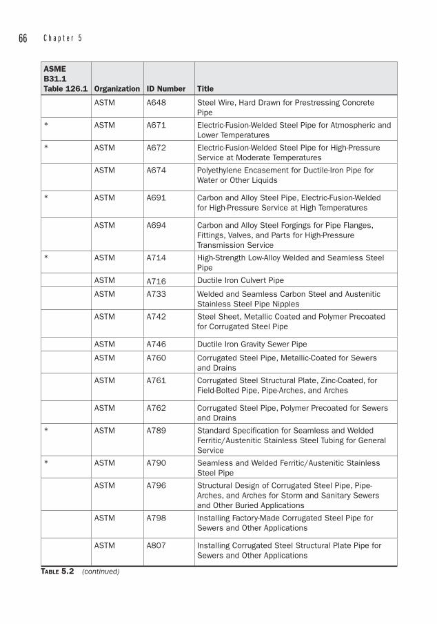
66 C h a p t e r 5
ASMEB31.1Table 126.1 Organization ID Number Title
ASTM A648 Steel Wire, Hard Drawn for Prestressing Concrete Pipe
* ASTM A671 Electric-Fusion-Welded Steel Pipe for Atmospheric and Lower Temperatures
* ASTM A672 Electric-Fusion-Welded Steel Pipe for High-Pressure Service at Moderate Temperatures
ASTM A674 Polyethylene Encasement for Ductile-Iron Pipe for Water or Other Liquids
* ASTM A691 Carbon and Alloy Steel Pipe, Electric-Fusion-Welded for High-Pressure Service at High Temperatures
ASTM A694 Carbon and Alloy Steel Forgings for Pipe Flanges, Fittings, Valves, and Parts for High-Pressure Transmission Service
* ASTM A714 High-Strength Low-Alloy Welded and Seamless Steel Pipe
ASTM A716 Ductile Iron Culvert Pipe
ASTM A733 Welded and Seamless Carbon Steel and Austenitic Stainless Steel Pipe Nipples
ASTM A742 Steel Sheet, Metallic Coated and Polymer Precoated for Corrugated Steel Pipe
ASTM A746 Ductile Iron Gravity Sewer Pipe
ASTM A760 Corrugated Steel Pipe, Metallic-Coated for Sewers and Drains
ASTM A761 Corrugated Steel Structural Plate, Zinc-Coated, for Field-Bolted Pipe, Pipe-Arches, and Arches
ASTM A762 Corrugated Steel Pipe, Polymer Precoated for Sewers and Drains
* ASTM A789 Standard Specification for Seamless and Welded Ferritic/Austenitic Stainless Steel Tubing for General Service
* ASTM A790 Seamless and Welded Ferritic/Austenitic Stainless Steel Pipe
ASTM A796 Structural Design of Corrugated Steel Pipe, Pipe-Arches, and Arches for Storm and Sanitary Sewers and Other Buried Applications
ASTM A798 Installing Factory-Made Corrugated Steel Pipe for Sewers and Other Applications
ASTM A807 Installing Corrugated Steel Structural Plate Pipe for Sewers and Other Applications
TABLE 5.2 (continued)
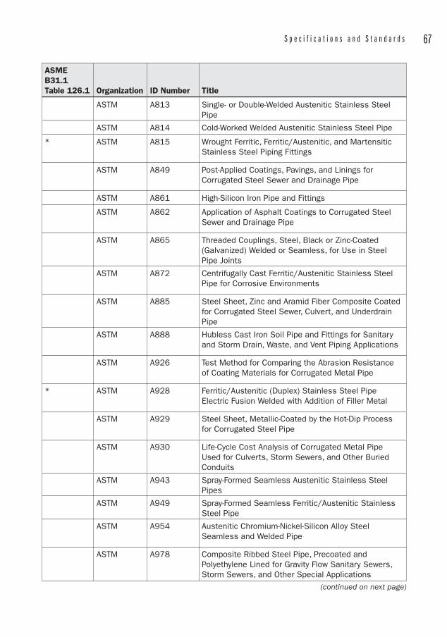
S p e c i f i c a t i o n s a n d S t a n d a r d s 67
ASMEB31.1Table 126.1 Organization ID Number Title
ASTM A813 Single- or Double-Welded Austenitic Stainless Steel Pipe
ASTM A814 Cold-Worked Welded Austenitic Stainless Steel Pipe
* ASTM A815 Wrought Ferritic, Ferritic/Austenitic, and Martensitic Stainless Steel Piping Fittings
ASTM A849 Post-Applied Coatings, Pavings, and Linings for Corrugated Steel Sewer and Drainage Pipe
ASTM A861 High-Silicon Iron Pipe and Fittings
ASTM A862 Application of Asphalt Coatings to Corrugated Steel Sewer and Drainage Pipe
ASTM A865 Threaded Couplings, Steel, Black or Zinc-Coated (Galvanized) Welded or Seamless, for Use in Steel Pipe Joints
ASTM A872 Centrifugally Cast Ferritic/Austenitic Stainless Steel Pipe for Corrosive Environments
ASTM A885 Steel Sheet, Zinc and Aramid Fiber Composite Coated for Corrugated Steel Sewer, Culvert, and Underdrain Pipe
ASTM A888 Hubless Cast Iron Soil Pipe and Fittings for Sanitary and Storm Drain, Waste, and Vent Piping Applications
ASTM A926 Test Method for Comparing the Abrasion Resistance of Coating Materials for Corrugated Metal Pipe
* ASTM A928 Ferritic/Austenitic (Duplex) Stainless Steel Pipe Electric Fusion Welded with Addition of Filler Metal
ASTM A929 Steel Sheet, Metallic-Coated by the Hot-Dip Process for Corrugated Steel Pipe
ASTM A930 Life-Cycle Cost Analysis of Corrugated Metal Pipe Used for Culverts, Storm Sewers, and Other Buried Conduits
ASTM A943 Spray-Formed Seamless Austenitic Stainless Steel Pipes
ASTM A949 Spray-Formed Seamless Ferritic/Austenitic Stainless Steel Pipe
ASTM A954 Austenitic Chromium-Nickel-Silicon Alloy Steel Seamless and Welded Pipe
ASTM A978 Composite Ribbed Steel Pipe, Precoated and Polyethylene Lined for Gravity Flow Sanitary Sewers, Storm Sewers, and Other Special Applications
(continued on next page)
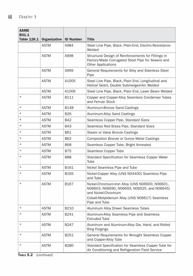
68 C h a p t e r 5
ASMEB31.1Table 126.1 Organization ID Number Title
ASTM A984 Steel Line Pipe, Black, Plain-End, Electric-Resistance-Welded
ASTM A998 Structural Design of Reinforcements for Fittings in Factory-Made Corrugated Steel Pipe for Sewers and Other Applications
ASTM A999 General Requirements for Alloy and Stainless Steel Pipe
ASTM A1005 Steel Line Pipe, Black, Plain End, Longitudinal and Helical Seam, Double Submerged-Arc Welded
ASTM A1006 Steel Line Pipe, Black, Plain End, Laser Beam Welded
* ASTM B111 Copper and Copper-Alloy Seamless Condenser Tubes and Ferrule Stock
* ASTM B148 Aluminum-Bronze Sand Castings
* ASTM B26 Aluminum-Alloy Sand Castings
* ASTM B42 Seamless Copper Pipe, Standard Sizes
* ASTM B43 Seamless Red Brass Pipe, Standard Sizes
* ASTM B61 Steam or Valve Bronze Castings
* ASTM B62 Composition Bronze or Ounce Metal Castings
* ASTM B68 Seamless Copper Tube, Bright Annealed
* ASTM B75 Seamless Copper Tube
* ASTM B88 Standard Specification for Seamless Copper Water Tube
* ASTM B161 Nickel Seamless Pipe and Tube
* ASTM B165 Nickel-Copper Alloy (UNS N04400) Seamless Pipe and Tube
* ASTM B167 Nickel-Chromium-Iron Alloy (UNS N06600, N06601, N06603, N06690, N06693, N06025, and N06645) and Nickel-Chromium-Cobalt-Molybdenum Alloy (UNS N06617) Seamless Pipe and Tube
* ASTM B210 Aluminum Alloy Drawn Seamless Tubes
* ASTM B241 Aluminum-Alloy Seamless Pipe and Seamless Extruded Tube
* ASTM B247 Aluminum and Aluminum-Alloy Die, Hand, and Rolled Ring Forgings
* ASTM B251 General Requirements for Wrought Seamless Copper and Copper-Alloy Tube
* ASTM B280 Standard Specification for Seamless Copper Tube for Air Conditioning and Refrigeration Field Service
TABLE 5.2 (continued)
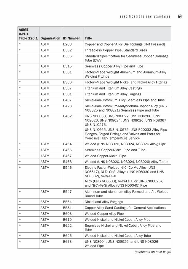
S p e c i f i c a t i o n s a n d S t a n d a r d s 69
ASMEB31.1Table 126.1 Organization ID Number Title
* ASTM B283 Copper and Copper-Alloy Die Forgings (Hot Pressed)
* ASTM B302 Threadless Copper Pipe, Standard Sizes
ASTM B306 Standard Specification for Seamless Copper Drainage Tube (DWV)
* ASTM B315 Seamless Copper Alloy Pipe and Tube
* ASTM B361 Factory-Made Wrought Aluminum and Aluminum-Alloy Welding Fittings
* ASTM B366 Factory-Made Wrought Nickel and Nickel Alloy Fittings
* ASTM B367 Titanium and Titanium Alloy Castings
* ASTM B381 Titanium and Titanium Alloy Forgings
* ASTM B407 Nickel-Iron-Chromium Alloy Seamless Pipe and Tube
* ASTM B423 Nickel-Iron-Chromium-Molybdenum-Copper Alloy (UNS N08825 and N08821) Seamless Pipe and Tube
* ASTM B462 UNS N06030, UNS N06022, UNS N06200, UNS N08020, UNS N08024, UNS N08026, UNS N08367, UNS N10276,UNS N10665, UNS N10675, UNS R20033 Alloy Pipe Flanges, Forged Fittings and Valves and Parts for Corrosive High-Temperature Service
* ASTM B464 Welded (UNS N08020, N08024, N08026 Alloy) Pipe
* ASTM B466 Seamless Copper-Nickel Pipe and Tube
* ASTM B467 Welded Copper-Nickel Pipe
* ASTM B468 Welded (UNS N08020, N08024, N08026) Alloy Tubes
* ASTM B546 Electric Fusion-Welded Ni-Cr-Co-Mo Alloy (UNS N06617), Ni-Fe-Cr-Si Alloys (UNS N08330 and UNS N08332), Ni-Cr-Fe-AlAlloy (UNS N06603), Ni-Cr-Fe Alloy (UNS N06025), and Ni-Cr-Fe-Si Alloy (UNS N06045) Pipe
* ASTM B547 Aluminum and Aluminum-Alloy Formed and Arc-Welded Round Tube
* ASTM B564 Nickel and Alloy Forgings
* ASTM B584 Copper Alloy Sand Castings for General Applications
* ASTM B603 Welded Copper-Alloy Pipe
* ASTM B619 Welded Nickel and Nickel-Cobalt Alloy Pipe
* ASTM B622 Seamless Nickel and Nickel-Cobalt Alloy Pipe and Tube
* ASTM B626 Welded Nickel and Nickel-Cobalt Alloy Tube
* ASTM B673 UNS N08904, UNS N08925, and UNS N08926 Welded Pipe
(continued on next page)

70 C h a p t e r 5
ASMEB31.1Table 126.1 Organization ID Number Title
* ASTM B674 UNS N08904, UNS N08925, and UNS N08926 Welded Tube
* ASTM B677 UNS N08904, UNS N08925, and UNS N08926 Seamless Pipe and Tube
* ASTM B704 Welded UNS N06625 and N08825 Alloy Tubes
* ASTM B705 Nickel-Alloy (UNS N06625 and N08825) Welded Pipe
* ASTM B729 Seamless UNS N08020, UNS N08026, and UNS N08024 Nickel-Alloy Pipe and Tube
ASTM B819 Standard Specification for Seamless Copper Tube for Medical Gas Systems
* ASTM B861 Titanium and Titanium Alloy Seamless Pipe
* ASTM B862 Titanium and Titanium Alloy Welded Pipe
ASTM D2241 Standard Specification for Polyvinyl Chloride Pressure-Rated Pipe (SDR Series)
ASTM E84 Standard Test Method for Surface Burning Characteristics of Building Materials
AWWA C104/A21.4
Cement-Mortar Lining for Ductile-Iron Pipe and Fittings for Water
AWWA C105/A21.5
Polyethylene Encasement for Ductile-Iron Pipe Systems
* AWWA C110/A21.10
Ductile-Iron and Gray-Iron Fittings for Water
* AWWA C111/A21.11
Rubber-Gasket Joints for Ductile-Iron Pressure Pipe and Fittings
* AWWA C115/A21.15
Flanged Ductile-Iron Pipe with Ductile-Iron or Gray-Iron Threaded Flanges
AWWA C116/A21.16
Protective Fusion-Bonded Epoxy Coatings Int. & Ext. Surf. Ductile-Iron/Gray-Iron Fittings
* AWWA C150/A21.50
Thickness Design of Ductile-Iron Pipe
* AWWA C151/A21.51
Ductile-Iron Pipe, Centrifugally Cast, for Water or Other Liquids
* AWWA C153/A21.53
Ductile-Iron Compact Fittings for Water Service
* AWWA C200 Steel Water Pipe 6 in (150 mm) and Larger
AWWA C203 Coal-Tar Protective Coatings & Linings for Steel Water Pipelines, Enamel & Tape, Hot-Applied
TABLE 5.2 (continued)
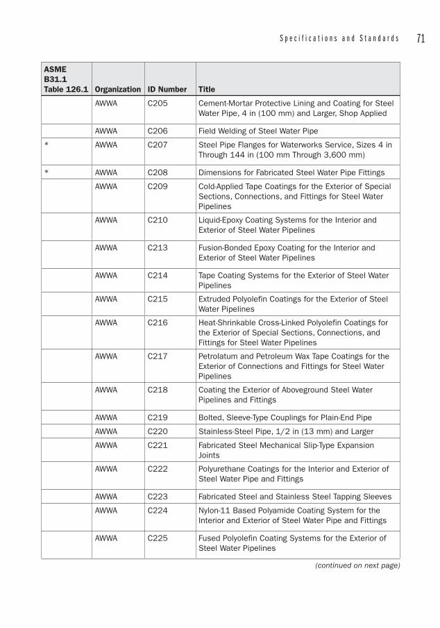
S p e c i f i c a t i o n s a n d S t a n d a r d s 71
ASMEB31.1Table 126.1 Organization ID Number Title
AWWA C205 Cement-Mortar Protective Lining and Coating for Steel Water Pipe, 4 in (100 mm) and Larger, Shop Applied
AWWA C206 Field Welding of Steel Water Pipe
* AWWA C207 Steel Pipe Flanges for Waterworks Service, Sizes 4 in Through 144 in (100 mm Through 3,600 mm)
* AWWA C208 Dimensions for Fabricated Steel Water Pipe Fittings
AWWA C209 Cold-Applied Tape Coatings for the Exterior of Special Sections, Connections, and Fittings for Steel Water Pipelines
AWWA C210 Liquid-Epoxy Coating Systems for the Interior and Exterior of Steel Water Pipelines
AWWA C213 Fusion-Bonded Epoxy Coating for the Interior and Exterior of Steel Water Pipelines
AWWA C214 Tape Coating Systems for the Exterior of Steel Water Pipelines
AWWA C215 Extruded Polyolefin Coatings for the Exterior of Steel Water Pipelines
AWWA C216 Heat-Shrinkable Cross-Linked Polyolefin Coatings for the Exterior of Special Sections, Connections, and Fittings for Steel Water Pipelines
AWWA C217 Petrolatum and Petroleum Wax Tape Coatings for the Exterior of Connections and Fittings for Steel Water Pipelines
AWWA C218 Coating the Exterior of Aboveground Steel Water Pipelines and Fittings
AWWA C219 Bolted, Sleeve-Type Couplings for Plain-End Pipe
AWWA C220 Stainless-Steel Pipe, 1/2 in (13 mm) and Larger
AWWA C221 Fabricated Steel Mechanical Slip-Type Expansion Joints
AWWA C222 Polyurethane Coatings for the Interior and Exterior of Steel Water Pipe and Fittings
AWWA C223 Fabricated Steel and Stainless Steel Tapping Sleeves
AWWA C224 Nylon-11 Based Polyamide Coating System for the Interior and Exterior of Steel Water Pipe and Fittings
AWWA C225 Fused Polyolefin Coating Systems for the Exterior of Steel Water Pipelines
(continued on next page)
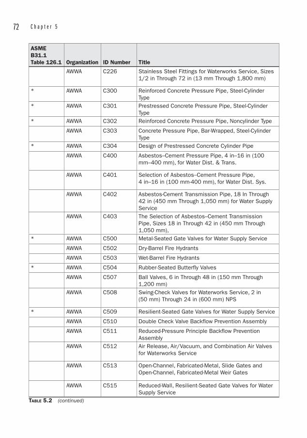
72 C h a p t e r 5
ASMEB31.1Table 126.1 Organization ID Number Title
AWWA C226 Stainless Steel Fittings for Waterworks Service, Sizes 1/2 in Through 72 in (13 mm Through 1,800 mm)
* AWWA C300 Reinforced Concrete Pressure Pipe, Steel-Cylinder Type
* AWWA C301 Prestressed Concrete Pressure Pipe, Steel-Cylinder Type
* AWWA C302 Reinforced Concrete Pressure Pipe, Noncylinder Type
AWWA C303 Concrete Pressure Pipe, Bar-Wrapped, Steel-Cylinder Type
* AWWA C304 Design of Prestressed Concrete Cylinder Pipe
AWWA C400 Asbestos–Cement Pressure Pipe, 4 in–16 in (100 mm–400 mm), for Water Dist. & Trans.
AWWA C401 Selection of Asbestos–Cement Pressure Pipe, 4 in–16 in (100 mm-400 mm), for Water Dist. Sys.
AWWA C402 Asbestos-Cement Transmission Pipe, 18 In Through 42 in (450 mm Through 1,050 mm) for Water Supply Service
AWWA C403 The Selection of Asbestos–Cement Transmission Pipe, Sizes 18 in Through 42 in (450 mm Through 1,050 mm),
* AWWA C500 Metal-Seated Gate Valves for Water Supply Service
AWWA C502 Dry-Barrel Fire Hydrants
AWWA C503 Wet-Barrel Fire Hydrants
* AWWA C504 Rubber-Seated Butterfly Valves
AWWA C507 Ball Valves, 6 in Through 48 in (150 mm Through 1,200 mm)
AWWA C508 Swing-Check Valves for Waterworks Service, 2 in (50 mm) Through 24 in (600 mm) NPS
* AWWA C509 Resilient-Seated Gate Valves for Water Supply Service
AWWA C510 Double Check Valve Backflow Prevention Assembly
AWWA C511 Reduced-Pressure Principle Backflow Prevention Assembly
AWWA C512 Air Release, Air/Vacuum, and Combination Air Valves for Waterworks Service
AWWA C513 Open-Channel, Fabricated-Metal, Slide Gates and Open-Channel, Fabricated-Metal Weir Gates
AWWA C515 Reduced-Wall, Resilient-Seated Gate Valves for Water Supply Service
TABLE 5.2 (continued)
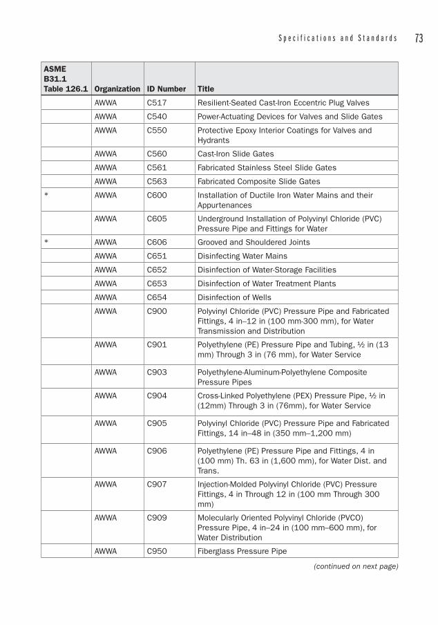
S p e c i f i c a t i o n s a n d S t a n d a r d s 73
ASMEB31.1Table 126.1 Organization ID Number Title
AWWA C517 Resilient-Seated Cast-Iron Eccentric Plug Valves
AWWA C540 Power-Actuating Devices for Valves and Slide Gates
AWWA C550 Protective Epoxy Interior Coatings for Valves and Hydrants
AWWA C560 Cast-Iron Slide Gates
AWWA C561 Fabricated Stainless Steel Slide Gates
AWWA C563 Fabricated Composite Slide Gates
* AWWA C600 Installation of Ductile Iron Water Mains and their Appurtenances
AWWA C605 Underground Installation of Polyvinyl Chloride (PVC) Pressure Pipe and Fittings for Water
* AWWA C606 Grooved and Shouldered Joints
AWWA C651 Disinfecting Water Mains
AWWA C652 Disinfection of Water-Storage Facilities
AWWA C653 Disinfection of Water Treatment Plants
AWWA C654 Disinfection of Wells
AWWA C900 Polyvinyl Chloride (PVC) Pressure Pipe and Fabricated Fittings, 4 in–12 in (100 mm-300 mm), for Water Transmission and Distribution
AWWA C901 Polyethylene (PE) Pressure Pipe and Tubing, ½ in (13 mm) Through 3 in (76 mm), for Water Service
AWWA C903 Polyethylene-Aluminum-Polyethylene Composite Pressure Pipes
AWWA C904 Cross-Linked Polyethylene (PEX) Pressure Pipe, ½ in (12mm) Through 3 in (76mm), for Water Service
AWWA C905 Polyvinyl Chloride (PVC) Pressure Pipe and Fabricated Fittings, 14 in–48 in (350 mm–1,200 mm)
AWWA C906 Polyethylene (PE) Pressure Pipe and Fittings, 4 in (100 mm) Th. 63 in (1,600 mm), for Water Dist. and Trans.
AWWA C907 Injection-Molded Polyvinyl Chloride (PVC) Pressure Fittings, 4 in Through 12 in (100 mm Through 300 mm)
AWWA C909 Molecularly Oriented Polyvinyl Chloride (PVCO) Pressure Pipe, 4 in–24 in (100 mm–600 mm), for Water Distribution
AWWA C950 Fiberglass Pressure Pipe
(continued on next page)
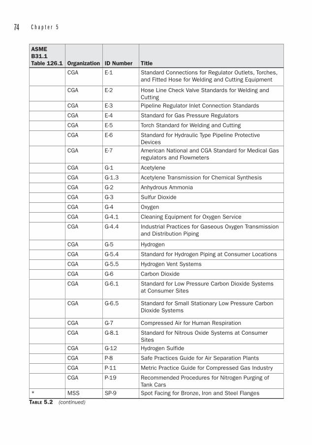
74 C h a p t e r 5
ASMEB31.1Table 126.1 Organization ID Number Title
CGA E-1 Standard Connections for Regulator Outlets, Torches, and Fitted Hose for Welding and Cutting Equipment
CGA E-2 Hose Line Check Valve Standards for Welding and Cutting
CGA E-3 Pipeline Regulator Inlet Connection Standards
CGA E-4 Standard for Gas Pressure Regulators
CGA E-5 Torch Standard for Welding and Cutting
CGA E-6 Standard for Hydraulic Type Pipeline Protective Devices
CGA E-7 American National and CGA Standard for Medical Gas regulators and Flowmeters
CGA G-1 Acetylene
CGA G-1.3 Acetylene Transmission for Chemical Synthesis
CGA G-2 Anhydrous Ammonia
CGA G-3 Sulfur Dioxide
CGA G-4 Oxygen
CGA G-4.1 Cleaning Equipment for Oxygen Service
CGA G-4.4 Industrial Practices for Gaseous Oxygen Transmission and Distribution Piping
CGA G-5 Hydrogen
CGA G-5.4 Standard for Hydrogen Piping at Consumer Locations
CGA G-5.5 Hydrogen Vent Systems
CGA G-6 Carbon Dioxide
CGA G-6.1 Standard for Low Pressure Carbon Dioxide Systems at Consumer Sites
CGA G-6.5 Standard for Small Stationary Low Pressure Carbon Dioxide Systems
CGA G-7 Compressed Air for Human Respiration
CGA G-8.1 Standard for Nitrous Oxide Systems at Consumer Sites
CGA G-12 Hydrogen Sulfide
CGA P-8 Safe Practices Guide for Air Separation Plants
CGA P-11 Metric Practice Guide for Compressed Gas Industry
CGA P-19 Recommended Procedures for Nitrogen Purging of Tank Cars
* MSS SP-9 Spot Facing for Bronze, Iron and Steel Flanges
TABLE 5.2 (continued)
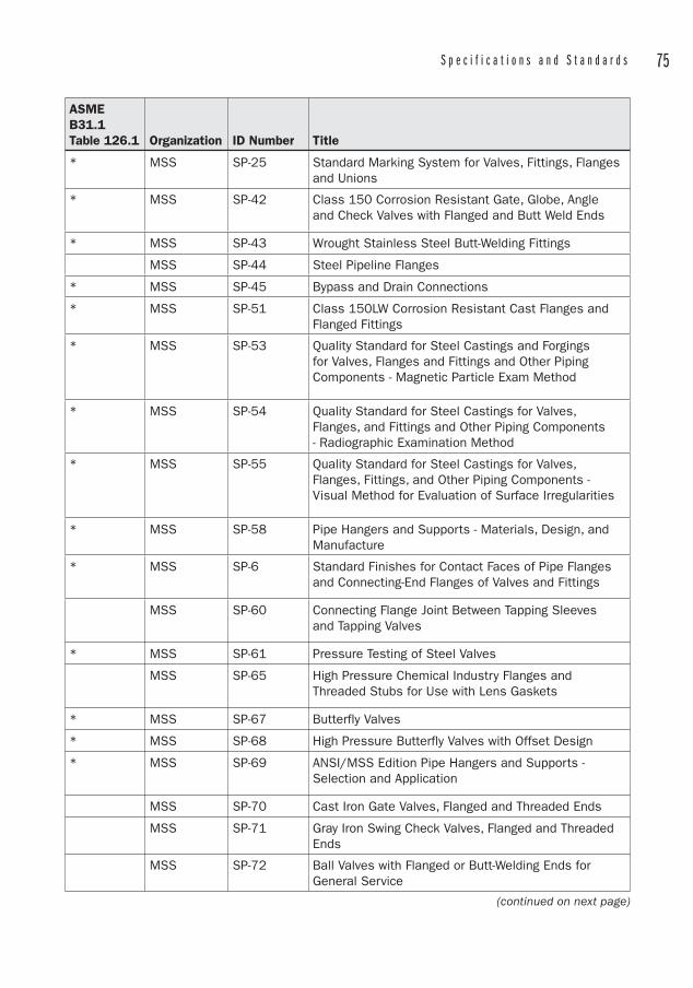
S p e c i f i c a t i o n s a n d S t a n d a r d s 75
ASMEB31.1Table 126.1 Organization ID Number Title
* MSS SP-25 Standard Marking System for Valves, Fittings, Flanges and Unions
* MSS SP-42 Class 150 Corrosion Resistant Gate, Globe, Angle and Check Valves with Flanged and Butt Weld Ends
* MSS SP-43 Wrought Stainless Steel Butt-Welding Fittings
MSS SP-44 Steel Pipeline Flanges
* MSS SP-45 Bypass and Drain Connections
* MSS SP-51 Class 150LW Corrosion Resistant Cast Flanges and Flanged Fittings
* MSS SP-53 Quality Standard for Steel Castings and Forgings for Valves, Flanges and Fittings and Other Piping Components - Magnetic Particle Exam Method
* MSS SP-54 Quality Standard for Steel Castings for Valves, Flanges, and Fittings and Other Piping Components - Radiographic Examination Method
* MSS SP-55 Quality Standard for Steel Castings for Valves, Flanges, Fittings, and Other Piping Components - Visual Method for Evaluation of Surface Irregularities
* MSS SP-58 Pipe Hangers and Supports - Materials, Design, and Manufacture
* MSS SP-6 Standard Finishes for Contact Faces of Pipe Flanges and Connecting-End Flanges of Valves and Fittings
MSS SP-60 Connecting Flange Joint Between Tapping Sleeves and Tapping Valves
* MSS SP-61 Pressure Testing of Steel Valves
MSS SP-65 High Pressure Chemical Industry Flanges and Threaded Stubs for Use with Lens Gaskets
* MSS SP-67 Butterfly Valves
* MSS SP-68 High Pressure Butterfly Valves with Offset Design
* MSS SP-69 ANSI/MSS Edition Pipe Hangers and Supports - Selection and Application
MSS SP-70 Cast Iron Gate Valves, Flanged and Threaded Ends
MSS SP-71 Gray Iron Swing Check Valves, Flanged and Threaded Ends
MSS SP-72 Ball Valves with Flanged or Butt-Welding Ends for General Service
(continued on next page)
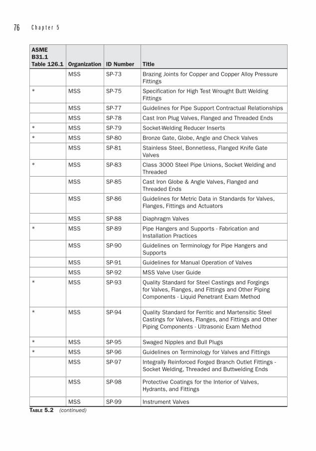
76 C h a p t e r 5
ASMEB31.1Table 126.1 Organization ID Number Title
MSS SP-73 Brazing Joints for Copper and Copper Alloy Pressure Fittings
* MSS SP-75 Specification for High Test Wrought Butt Welding Fittings
MSS SP-77 Guidelines for Pipe Support Contractual Relationships
MSS SP-78 Cast Iron Plug Valves, Flanged and Threaded Ends
* MSS SP-79 Socket-Welding Reducer Inserts
* MSS SP-80 Bronze Gate, Globe, Angle and Check Valves
MSS SP-81 Stainless Steel, Bonnetless, Flanged Knife Gate Valves
* MSS SP-83 Class 3000 Steel Pipe Unions, Socket Welding and Threaded
MSS SP-85 Cast Iron Globe & Angle Valves, Flanged and Threaded Ends
MSS SP-86 Guidelines for Metric Data in Standards for Valves, Flanges, Fittings and Actuators
MSS SP-88 Diaphragm Valves
* MSS SP-89 Pipe Hangers and Supports - Fabrication and Installation Practices
MSS SP-90 Guidelines on Terminology for Pipe Hangers and Supports
MSS SP-91 Guidelines for Manual Operation of Valves
MSS SP-92 MSS Valve User Guide
* MSS SP-93 Quality Standard for Steel Castings and Forgings for Valves, Flanges, and Fittings and Other Piping Components - Liquid Penetrant Exam Method
* MSS SP-94 Quality Standard for Ferritic and Martensitic Steel Castings for Valves, Flanges, and Fittings and Other Piping Components - Ultrasonic Exam Method
* MSS SP-95 Swaged Nipples and Bull Plugs
* MSS SP-96 Guidelines on Terminology for Valves and Fittings
MSS SP-97 Integrally Reinforced Forged Branch Outlet Fittings - Socket Welding, Threaded and Buttwelding Ends
MSS SP-98 Protective Coatings for the Interior of Valves, Hydrants, and Fittings
MSS SP-99 Instrument Valves TABLE 5.2 (continued)
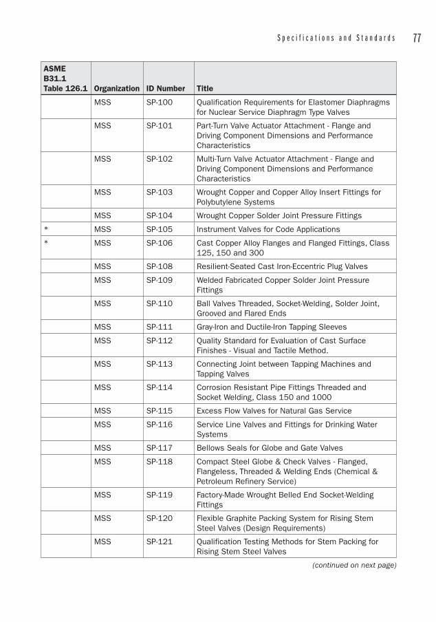
S p e c i f i c a t i o n s a n d S t a n d a r d s 77
ASMEB31.1Table 126.1 Organization ID Number Title
MSS SP-100 Qualification Requirements for Elastomer Diaphragms for Nuclear Service Diaphragm Type Valves
MSS SP-101 Part-Turn Valve Actuator Attachment - Flange and Driving Component Dimensions and Performance Characteristics
MSS SP-102 Multi-Turn Valve Actuator Attachment - Flange and Driving Component Dimensions and Performance Characteristics
MSS SP-103 Wrought Copper and Copper Alloy Insert Fittings for Polybutylene Systems
MSS SP-104 Wrought Copper Solder Joint Pressure Fittings
* MSS SP-105 Instrument Valves for Code Applications
* MSS SP-106 Cast Copper Alloy Flanges and Flanged Fittings, Class 125, 150 and 300
MSS SP-108 Resilient-Seated Cast Iron-Eccentric Plug Valves
MSS SP-109 Welded Fabricated Copper Solder Joint Pressure Fittings
MSS SP-110 Ball Valves Threaded, Socket-Welding, Solder Joint, Grooved and Flared Ends
MSS SP-111 Gray-Iron and Ductile-Iron Tapping Sleeves
MSS SP-112 Quality Standard for Evaluation of Cast Surface Finishes - Visual and Tactile Method.
MSS SP-113 Connecting Joint between Tapping Machines and Tapping Valves
MSS SP-114 Corrosion Resistant Pipe Fittings Threaded and Socket Welding, Class 150 and 1000
MSS SP-115 Excess Flow Valves for Natural Gas Service
MSS SP-116 Service Line Valves and Fittings for Drinking Water Systems
MSS SP-117 Bellows Seals for Globe and Gate Valves
MSS SP-118 Compact Steel Globe & Check Valves - Flanged, Flangeless, Threaded & Welding Ends (Chemical & Petroleum Refinery Service)
MSS SP-119 Factory-Made Wrought Belled End Socket-Welding Fittings
MSS SP-120 Flexible Graphite Packing System for Rising Stem Steel Valves (Design Requirements)
MSS SP-121 Qualification Testing Methods for Stem Packing for Rising Stem Steel Valves
(continued on next page)
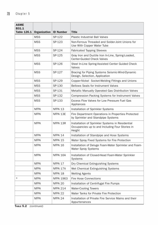
78 C h a p t e r 5
ASMEB31.1Table 126.1 Organization ID Number Title
MSS SP-122 Plastic Industrial Ball Valves
MSS SP-123 Non-Ferrous Threaded and Solder-Joint Unions for Use With Copper Water Tube
MSS SP-124 Fabricated Tapping Sleeves
MSS SP-125 Gray Iron and Ductile Iron In-Line, Spring-Loaded, Center-Guided Check Valves
MSS SP-126 Steel In-Line Spring-Assisted Center Guided Check Valves
MSS SP-127 Bracing for Piping Systems Seismic-Wind-Dynamic Design, Selection, Application
MSS SP-129 Copper-Nickel Socket-Welding Fittings and Unions
MSS SP-130 Bellows Seals for Instrument Valves
MSS SP-131 Metallic Manually Operated Gas Distribution Valves
MSS SP-132 Compression Packing Systems for Instrument Valves
MSS SP-133 Excess Flow Valves for Low Pressure Fuel Gas Appliances
NFPA NFPA 13 Installation of Sprinkler Systems
NFPA NFPA 13E Fire Department Operations in Properties Protected by Sprinkler and Standpipe Systems
NFPA NFPA 13R Installation of Sprinkler Systems in Residential Occupancies up to and Including Four Stories in Height
NFPA NFPA 14 Installation of Standpipe and Hose Systems
NFPA NFPA 15 Water Spray Fixed Systems for Fire Protection
NFPA NFPA 16 Installation of Deluge Foam-Water Sprinkler and Foam-Water Spray Systems
NFPA NFPA 16A Installation of Closed-Head Foam-Water Sprinkler Systems
NFPA NFPA 17 Dry Chemical Extinguishing Systems
NFPA NFPA 17A Wet Chemical Extinguishing Systems
NFPA NFPA 18 Wetting Agents
* NFPA NFPA 1963 Fire Hose Connections
NFPA NFPA 20 Installation of Centrifugal Fire Pumps
NFPA NFPA 214 Water-Cooling Towers
NFPA NFPA 22 Water Tanks for Private Fire Protection
NFPA NFPA 24 Installation of Private Fire Service Mains and their Appurtenances
TABLE 5.2 (continued)

S p e c i f i c a t i o n s a n d S t a n d a r d s 79
ASMEB31.1Table 126.1 Organization ID Number Title
NFPA NFPA 25 Inspection, Testing and Maintenance of Water-Based Fire Protection Systems
NFPA NFPA 30 Flammable and Combustible Liquids Code
NFPA NFPA 31 Installation of Oil-Burning Equipment
NFPA NFPA 325 Fire Hazard Properties of Flammable Liquids, Gases, and Volatile Solids
NFPA NFPA 328 Control of Flammable and Combustible Liquids and Gases in Manholes, Sewers, and Similar Underground Structures
NFPA NFPA 37 Installation of Stationary Combustion Engines and Gas Turbines
NFPA NFPA 45 Fire Protection for Laboratories Using Chemicals
NFPA NFPA 49 Hazardous Chemicals Data
NFPA NFPA 491 Hazardous Chemical reactions
NFPA NFPA 497 Classification of Flammable Liquids, Gases or Vapors and of Hazardous (classified) Locations for Electrical Installations in Chemical Process Areas
NFPA NFPA 50 Bulk Oxygen Systems at Consumer Sites
NFPA NFPA 50A Gaseous Hydrogen Systems at Consumer Sites
NFPA NFPA 50B Liquified Hydrogen Systems at Consumer Sites
NFPA NFPA 51 Design and Installation of Oxygen-Fuel Gas Systems for Welding, Cutting, and Allied Processes
NFPA NFPA 54 National Fuel Gas Code
NFPA NFPA 57 Liquified Natural Gas (LNG) Vehicular Fuel Systems
NFPA NFPA 58 Storage and Handling of Liquified Petroleum Gases
NFPA NFPA 59 Storage and Handling of Liquified Petroleum Gases at Utility Gas Plants
NFPA NFPA 600 Industrial Fire Brigades
NFPA NFPA 70 National Electric Code
NFPA NFPA 99C Gas and Vacuum Systems
NSF 14 Plastics Piping System Components and Related Materials
NSF 61 Drinking water system components - Health effects
PFI ES1 Internal Machining and Solid Machined Backing Rings For Circumferential Butt Welds
(continued on next page)
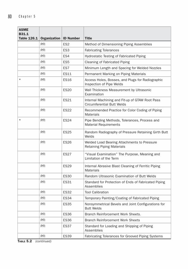
80 C h a p t e r 5
ASMEB31.1Table 126.1 Organization ID Number Title
PFI ES2 Method of Dimensioning Piping Assemblies
PFI ES3 Fabricating Tolerances
PFI ES4 Hydrostatic Testing of Fabricated Piping
PFI ES5 Cleaning of Fabricated Piping
PFI ES7 Minimum Length and Spacing for Welded Nozzles
PFI ES11 Permanent Marking on Piping Materials
* PFI ES16 Access Holes, Bosses, and Plugs for Radiographic Inspection of Pipe Welds
PFI ES20 Wall Thickness Measurement by Ultrasonic Examination
PFI ES21 Internal Machining and Fit-up of GTAW Root Pass Circumferential Butt Welds
PFI ES22 Recommended Practice for Color Coding of Piping Materials
* PFI ES24 Pipe Bending Methods, Tolerances, Process and Material Requirements
PFI ES25 Random Radiography of Pressure Retaining Girth Butt Welds
PFI ES26 Welded Load Bearing Attachments to Pressure Retaining Piping Materials
PFI ES27 “Visual Examination” The Purpose, Meaning and Limitation of the Term
PFI ES29 Internal Abrasive Blast Cleaning of Ferritic Piping Materials
PFI ES30 Random Ultrasonic Examination of Butt Welds
PFI ES31 Standard for Protection of Ends of Fabricated Piping Assemblies
PFI ES32 Tool Calibration
PFI ES34 Temporary Painting/Coating of Fabricated Piping
PFI ES35 Nonsymmetrical Bevels and Joint Configurations for Butt Welds
PFI ES36 Branch Reinforcement Work Sheets.
PFI ES36 Branch Reinforcement Work Sheets
PFI ES37 Standard for Loading and Shipping of Piping Assemblies
PFI ES39 Fabricating Tolerances for Grooved Piping SystemsTABLE 5.2 (continued)
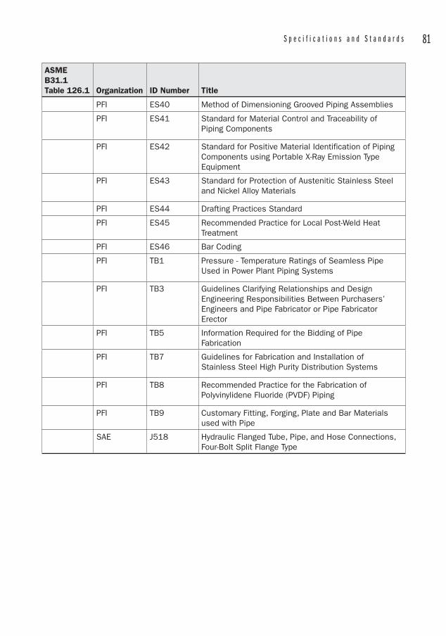
S p e c i f i c a t i o n s a n d S t a n d a r d s 81
ASMEB31.1Table 126.1 Organization ID Number Title
PFI ES40 Method of Dimensioning Grooved Piping Assemblies
PFI ES41 Standard for Material Control and Traceability of Piping Components
PFI ES42 Standard for Positive Material Identification of Piping Components using Portable X-Ray Emission Type Equipment
PFI ES43 Standard for Protection of Austenitic Stainless Steel and Nickel Alloy Materials
PFI ES44 Drafting Practices Standard
PFI ES45 Recommended Practice for Local Post-Weld Heat Treatment
PFI ES46 Bar Coding
PFI TB1 Pressure - Temperature Ratings of Seamless Pipe Used in Power Plant Piping Systems
PFI TB3 Guidelines Clarifying Relationships and Design Engineering Responsibilities Between Purchasers’ Engineers and Pipe Fabricator or Pipe Fabricator Erector
PFI TB5 Information Required for the Bidding of Pipe Fabrication
PFI TB7 Guidelines for Fabrication and Installation of Stainless Steel High Purity Distribution Systems
PFI TB8 Recommended Practice for the Fabrication of Polyvinylidene Fluoride (PVDF) Piping
PFI TB9 Customary Fitting, Forging, Plate and Bar Materials used with Pipe
SAE J518 Hydraulic Flanged Tube, Pipe, and Hose Connections, Four-Bolt Split Flange Type
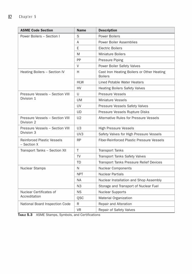
82 C h a p t e r 5
ASME Code Section Name Description
Power Boilers – Section I S Power Boilers
A Power Boiler Assemblies
E Electric Boilers
M Miniature Boilers
PP Pressure Piping
V Power Boiler Safety Valves
Heating Boilers – Section IV H Cast Iron Heating Boilers or Other Heating Boilers
HLW Lined Potable Water Heaters
HV Heating Boilers Safety Valves
Pressure Vessels – Section VIII Division 1
U Pressure Vessels
UM Miniature Vessels
UV Pressure Vessels Safety Valves
UD Pressure Vessels Rupture Disks
Pressure Vessels – Section VIII Division 2
U2 Alternative Rules for Pressure Vessels
Pressure Vessels – Section VIII Division 3
U3 High Pressure Vessels
UV3 Safety Valves for High Pressure Vessels
Reinforced Plastic Vessels – Section X
RP Fiber-Reinforced Plastic Pressure Vessels
Transport Tanks – Section XII T Transport Tanks
TV Transport Tanks Safety Valves
TD Transport Tanks Pressure Relief Devices
Nuclear Stamps N Nuclear Components
NPT Nuclear Partials
NA Nuclear Installation and Shop Assembly
N3 Storage and Transport of Nuclear Fuel
Nuclear Certificates of Accreditation
NS Nuclear Supports
QSC Material Organization
National Board Inspection Code R Repair and Alteration
VR Repair of Safety ValvesTABLE 5.3 ASME Stamps, Symbols, and Certifications
83
CHAPTER 6Materials of Construction
At a Fortune 500 company, a young engineer had designed a hot water system for a pilot plant using PVC . He may have thought he was doing a good job by saving money over the cost of a copper or steel system, but when one of the lines ruptured, it showered two workers with scalding water. One was hospitalized. At 140°F, PVC is only capable of withstanding 22 percent of its working pressure at 73°F.
At a plant I visited in Chicago, I observed a PVC line extending out of an air receiver on a compressed air system. Not only was this time bomb a poor application of material, but the compressor was an unanchored reciprocating compressor, which had “walked” on the floor, further stressing the PVC.
PVC is a perfectly acceptable material for the applications for which it is designed. If you expose it to high temperature, high pressure, shock loads, or the sun, you can expect failure in a short time. The failure may be accompanied by property
damage, shrieking, or worse. There are really only a few piping materials in common use. You will often see
reference books provide data on materials like borosilicate glass piping, but applications for this are uncommon outside of laboratory settings. One obsolete use of borosilicate piping is for coolant piping in electronics equipment that used vacuum tubes.
Likewise, data for wood stave piping and terra cotta are common, even though such applications are out-of-date. One can still observe wood stave construction in old cooling tower installations1 and terra cotta house drains, but no one would ever design a new system using these materials2.
So the remaining common materials break down into the following categories:
Ferrous Metal Piping• Cast iron• Ductile iron• Carbon steel
• Stainless steel
1 At a paper mill in North Carolina, wooden water tanks were still in use as recently as 2004. The maintenance superintendent loved them because they required no painting and did not corrode. Small leaks were sealed by tossing a few handfuls of sawdust into the open top of the tank.2 Although some in the “green” building movement advocate clay pipe as an environmentally friendly MOC.
Non-ferrous metal piping• Copper• Brass• Titanium• Aluminum
84 C h a p t e r 6
Plastics• PVC • CPVC • PB• HDPE • ABS • PEX
Composites • FRP • Concrete• Lined pipe
Many of these materials are represented by technical organizations that publish manuals to aid in the design of piping systems constructed of such materials. These manuals contain useful data for applications that are specific to the material under consideration. It’s also worthy to note that these organizations are very competitive with one another. Aside from providing technical data, they often cast the products they represent in a favorable light compared to other products. It is therefore the engineer’s responsibility to determine which is the best material for the application, based on the available data, economics, and prior experience.
Upon examining any of the various tables that describe what sizes and wall thicknesses of pipe are available, the reader will note that the critical dimension in every case is the outside diameter. In the world of piping, the outside diameter only occasionally matches exactly with the nominal diameter . This is essentially the difference between piping and tubing.
Tubing is specified in two ways:
1. It may be specified by OD and wall thickness 2. It may be specified by ID and wall thickness.
Piping is specified by nominal diameter and wall thickness . The wall thickness may be referred to as “pressure class,” “thickness class, ” “schedule, ” or “weight, ” depending on the material.
The selection of materials is of paramount importance to the piping engineer. Some of the criteria used to select a material include chemical compatibility, system cleanliness requirements, service life, allowable stress, availability, ease of repair, and economy.
Casting versus ForgingIn addition to specifying the correct material for a pipe or fitting, it is important to understand the way in which the item was manufactured. In general, metals that are cast are more brittle, and therefore more susceptible to fracture, than are forged metals. However, there are varying degrees of strength among cast metals as well. Hence, cast iron is weaker than cast steel. This is why cast iron reducing bushings are not permitted for use in fuel gas piping, but cast steel bushings are.
Given a choice, the forged materials will be the better selection due to their ability to withstand abuse. Over-tightening a cast threaded fitting will often result in a stress fracture. Castings are not easily welded. Castings may have surface imperfections due to improper cleaning of the mold.
Forging work-hardens the metal and imparts greater durability. Forged metals withstand higher stresses. Forged steel fittings are easily welded. The term “wrought, ” as in wrought iron or wrought copper indicates a forging process.
However, engineering is the science of making choices, or compromises, and those choices are often based as much on economics as technical merit. Castings often represent the least expensive installed cost.
M a t e r i a l s o f C o n s t r u c t i o n 85
Cast Iron Pipe Commercially manufactured cast iron contains between 2 and 6.67 percent carbon. These metals are exceptionally strong in compression, but are very brittle. They have very low ductility and malleability, and cannot be drawn, rolled, or worked at room temperature. A sharp blow with a sledge hammer can crack a cast iron pipe.
Cast irons melt readily however, and can be cast into complicated shapes and machined. This property suits them for some valve bodies.
A distinction is drawn between “cast ” iron and “ductile” iron. While ductile irons are also cast, the terms distinguish the metallographic structures of the materials. Cast iron describes a metallographic structure in which the carbon exists in the form of graphite flakes. The graphite is essentially carbon, chemically uncombined with any other elements. This structure is known as “gray cast iron” or simply “cast iron.” The larger the graphite flakes are, the weaker the metal is. The flakes form stress concentrations at the microscopic level.
ApplicationsCast iron was probably the first metal used for piping. The first recorded use of it was for a fountain in Langensalza, Germany circa 1562. A water distribution system was installed in France in 1664 for the palace of Versailles, and is allegedly still in use.
Because it is so brittle, it is not often used for pressure piping applications, although ASME B31.3 contains Basic Allowable Stress data for gray cast iron pipe. Cast iron pipe is now used primarily for drain, waste, and vent (DWV) applications, which is also known as “soil pipe.”
Once used for water distribution piping, cast iron is now relegated to drain, waste, and vent service, due to the improved metallurgy provided by other materials, especially ductile iron. Cast iron water mains are still in service throughout the world however, in aging infrastructure.
Applicable SpecificationsANSI/AWWA C105/A 21.5 American National Standard for Polyethylene
Encasement for Ductile-Iron Pipe SystemsANSI/AWWA C110/A21.10 Ductile-Iron and Gray-Iron Fittings for WaterANSI/AWWA C115/A21.15 Flanged Ductile-Iron Pipe with Ductile-Iron or
Gray-Iron Threaded FlangesANSI/AWWA C116/A21.16 Protective Fusion-Bonded Epoxy Coatings for the
Interior and Exterior Surfaces of Ductile-Iron/Gray-Iron Fittings for Water Supply Service
ASME/ANSI B 16.45 Cast Iron Fittings for Sovent® Drainage Systems. ASSE 1043 Cast Iron Fittings for Sovent ® Drainage SystemsASTM A-74 Standard Specification for Cast Iron Soil Pipe and
FittingsASTM A-674 Standard Practice for Polyethylene Encasement for
Ductile Iron Pipe for Water or Other Liquids. ASTM A-888 Standard Specification for Hubless Cast Iron Soil Pipe
and Fittings for Sanitary and Storm Drain, Waste, and Vent Piping Applications
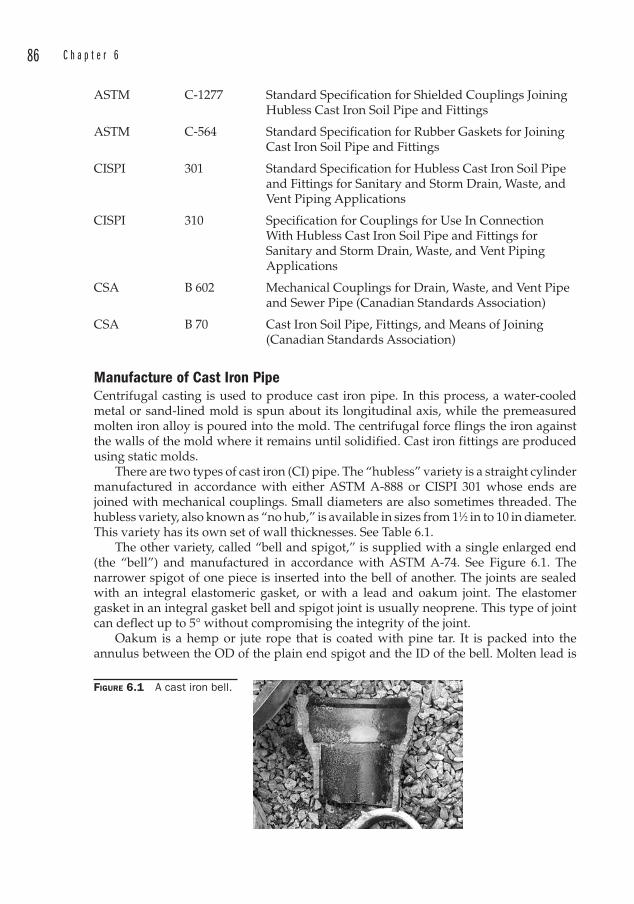
86 C h a p t e r 6
ASTM C-1277 Standard Specification for Shielded Couplings Joining Hubless Cast Iron Soil Pipe and Fittings
ASTM C-564 Standard Specification for Rubber Gaskets for Joining Cast Iron Soil Pipe and Fittings
CISPI 301 Standard Specification for Hubless Cast Iron Soil Pipe and Fittings for Sanitary and Storm Drain, Waste, and Vent Piping Applications
CISPI 310 Specification for Couplings for Use In Connection With Hubless Cast Iron Soil Pipe and Fittings for Sanitary and Storm Drain, Waste, and Vent Piping Applications
CSA B 602 Mechanical Couplings for Drain, Waste, and Vent Pipe and Sewer Pipe (Canadian Standards Association)
CSA B 70 Cast Iron Soil Pipe, Fittings, and Means of Joining (Canadian Standards Association)
Manufacture of Cast Iron Pipe Centrifugal casting is used to produce cast iron pipe. In this process, a water-cooled metal or sand-lined mold is spun about its longitudinal axis, while the premeasured molten iron alloy is poured into the mold. The centrifugal force flings the iron against the walls of the mold where it remains until solidified. Cast iron fittings are produced using static molds.
There are two types of cast iron (CI) pipe. The “hubless ” variety is a straight cylinder manufactured in accordance with either ASTM A-888 or CISPI 301 whose ends are joined with mechanical couplings. Small diameters are also sometimes threaded. The hubless variety, also known as “no hub,” is available in sizes from 11⁄2 in to 10 in diameter. This variety has its own set of wall thicknesses. See Table 6.1.
The other variety, called “bell and spigot, ” is supplied with a single enlarged end (the “bell”) and manufactured in accordance with ASTM A-74. See Figure 6.1. The narrower spigot of one piece is inserted into the bell of another. The joints are sealed with an integral elastomeric gasket, or with a lead and oakum joint. The elastomer gasket in an integral gasket bell and spigot joint is usually neoprene. This type of joint can deflect up to 5° without compromising the integrity of the joint.
Oakum is a hemp or jute rope that is coated with pine tar. It is packed into the annulus between the OD of the plain end spigot and the ID of the bell. Molten lead is
FIGURE 6.1 A cast iron bell.
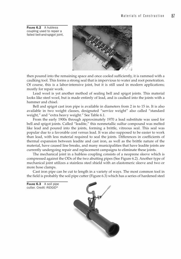
M a t e r i a l s o f C o n s t r u c t i o n 87
then poured into the remaining space and once cooled sufficiently, it is rammed with a caulking tool. This forms a strong seal that is impervious to water and root penetration. Of course, this is a labor-intensive joint, but it is still used in modern applications; mostly for repair work.
Lead wool is yet another method of sealing bell and spigot joints. This material looks like steel wool, but is made entirely of lead, and is caulked into the joints with a hammer and chisel.
Bell and spigot cast iron pipe is available in diameters from 2 in to 15 in. It is also available in two weight classes, designated “service weight” also called “standard weight,” and “extra heavy weight.” See Table 6.1.
From the early 1900s through approximately 1970 a lead substitute was used for bell and spigot joints. Called “leadite, ” this nonmetallic sulfur compound was melted like lead and poured into the joints, forming a brittle, vitreous seal. This seal was popular due to a favorable cost versus lead. It was also supposed to be easier to work than lead, with less material required to seal the joints. Differences in coefficients of thermal expansion between leadite and cast iron, as well as the brittle nature of the material, have caused line breaks, and many municipalities that have leadite joints are currently undergoing repair and replacement campaigns to eliminate these joints.
The mechanical joint in a hubless coupling consists of a neoprene sleeve which is compressed against the ODs of the two abutting pipes (See Figure 6.2). Another type of mechanical joint utilizes a stainless steel shield with an elastomeric sleeve and two or more hose clamps.
Cast iron pipe can be cut to length in a variety of ways. The most common tool in the field is probably the soil pipe cutter (Figure 6.3) which has a series of hardened steel
FIGURE 6.2 A hubless coupling used to repair a failed bell-and-spigot joint.
FIGURE 6.3 A soil pipe cutter. Credit: RIDGID®
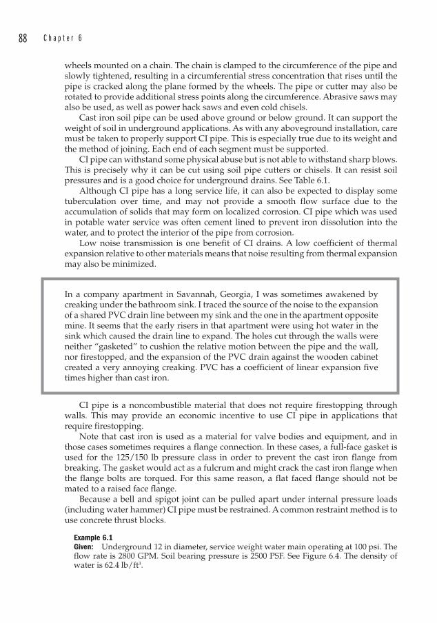
88 C h a p t e r 6
wheels mounted on a chain. The chain is clamped to the circumference of the pipe and slowly tightened, resulting in a circumferential stress concentration that rises until the pipe is cracked along the plane formed by the wheels. The pipe or cutter may also be rotated to provide additional stress points along the circumference. Abrasive saws may also be used, as well as power hack saws and even cold chisels.
Cast iron soil pipe can be used above ground or below ground. It can support the weight of soil in underground applications. As with any aboveground installation, care must be taken to properly support CI pipe. This is especially true due to its weight and the method of joining. Each end of each segment must be supported.
CI pipe can withstand some physical abuse but is not able to withstand sharp blows. This is precisely why it can be cut using soil pipe cutters or chisels. It can resist soil pressures and is a good choice for underground drains. See Table 6.1.
Although CI pipe has a long service life, it can also be expected to display some tuberculation over time, and may not provide a smooth flow surface due to the accumulation of solids that may form on localized corrosion. CI pipe which was used in potable water service was often cement lined to prevent iron dissolution into the water, and to protect the interior of the pipe from corrosion.
Low noise transmission is one benefit of CI drains. A low coefficient of thermal expansion relative to other materials means that noise resulting from thermal expansion may also be minimized.
In a company apartment in Savannah, Georgia, I was sometimes awakened by creaking under the bathroom sink. I traced the source of the noise to the expansion of a shared PVC drain line between my sink and the one in the apartment opposite mine. It seems that the early risers in that apartment were using hot water in the sink which caused the drain line to expand. The holes cut through the walls were neither “gasketed” to cushion the relative motion between the pipe and the wall, nor firestopped, and the expansion of the PVC drain against the wooden cabinet created a very annoying creaking. PVC has a coefficient of linear expansion five times higher than cast iron.
CI pipe is a noncombustible material that does not require firestopping through walls. This may provide an economic incentive to use CI pipe in applications that require firestopping.
Note that cast iron is used as a material for valve bodies and equipment, and in those cases sometimes requires a flange connection. In these cases, a full-face gasket is used for the 125/150 lb pressure class in order to prevent the cast iron flange from breaking. The gasket would act as a fulcrum and might crack the cast iron flange when the flange bolts are torqued. For this same reason, a flat faced flange should not be mated to a raised face flange.
Because a bell and spigot joint can be pulled apart under internal pressure loads (including water hammer) CI pipe must be restrained. A common restraint method is to use concrete thrust blocks.
Example 6.1Given: Underground 12 in diameter, service weight water main operating at 100 psi. The flow rate is 2800 GPM. Soil bearing pressure is 2500 PSF. See Figure 6.4. The density of water is 62.4 lb/ft3.
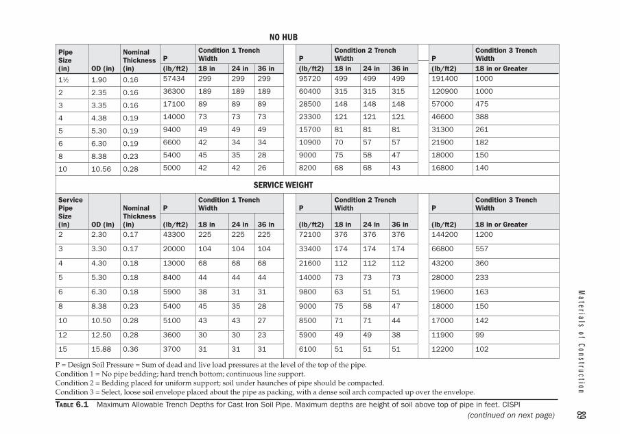
Materials of Construction
89 NO HUB
PipeSize(in) OD (in)
NominalThickness(in)
PCondition 1 Trench Width P
Condition 2 Trench Width P
Condition 3 Trench Width
(lb/ft2) 18 in 24 in 36 in (lb/ft2) 18 in 24 in 36 in (lb/ft2) 18 in or Greater
11⁄2 1.90 0.16 57434 299 299 299 95720 499 499 499 191400 1000
2 2.35 0.16 36300 189 189 189 60400 315 315 315 120900 1000
3 3.35 0.16 17100 89 89 89 28500 148 148 148 57000 475
4 4.38 0.19 14000 73 73 73 23300 121 121 121 46600 388
5 5.30 0.19 9400 49 49 49 15700 81 81 81 31300 261
6 6.30 0.19 6600 42 34 34 10900 70 57 57 21900 182
8 8.38 0.23 5400 45 35 28 9000 75 58 47 18000 150
10 10.56 0.28 5000 42 42 26 8200 68 68 43 16800 140
SERVICE WEIGHT
Service PipeSize(in) OD (in)
NominalThickness(in)
PCondition 1 Trench Width P
Condition 2 Trench Width P
Condition 3 Trench Width
(lb/ft2) 18 in 24 in 36 in (lb/ft2) 18 in 24 in 36 in (lb/ft2) 18 in or Greater2 2.30 0.17 43300 225 225 225 72100 376 376 376 144200 1200
3 3.30 0.17 20000 104 104 104 33400 174 174 174 66800 557
4 4.30 0.18 13000 68 68 68 21600 112 112 112 43200 360
5 5.30 0.18 8400 44 44 44 14000 73 73 73 28000 233
6 6.30 0.18 5900 38 31 31 9800 63 51 51 19600 163
8 8.38 0.23 5400 45 35 28 9000 75 58 47 18000 150
10 10.50 0.28 5100 43 43 27 8500 71 71 44 17000 142
12 12.50 0.28 3600 30 30 23 5900 49 49 38 11900 99
15 15.88 0.36 3700 31 31 31 6100 51 51 51 12200 102
P = Design Soil Pressure = Sum of dead and live load pressures at the level of the top of the pipe.Condition 1 = No pipe bedding; hard trench bottom; continuous line support.Condition 2 = Bedding placed for uniform support; soil under haunches of pipe should be compacted.Condition 3 = Select, loose soil envelope placed about the pipe as packing, with a dense soil arch compacted up over the envelope.
TABLE 6.1 Maximum Allowable Trench Depths for Cast Iron Soil Pipe. Maximum depths are height of soil above top of pipe in feet. CISPI(continued on next page)
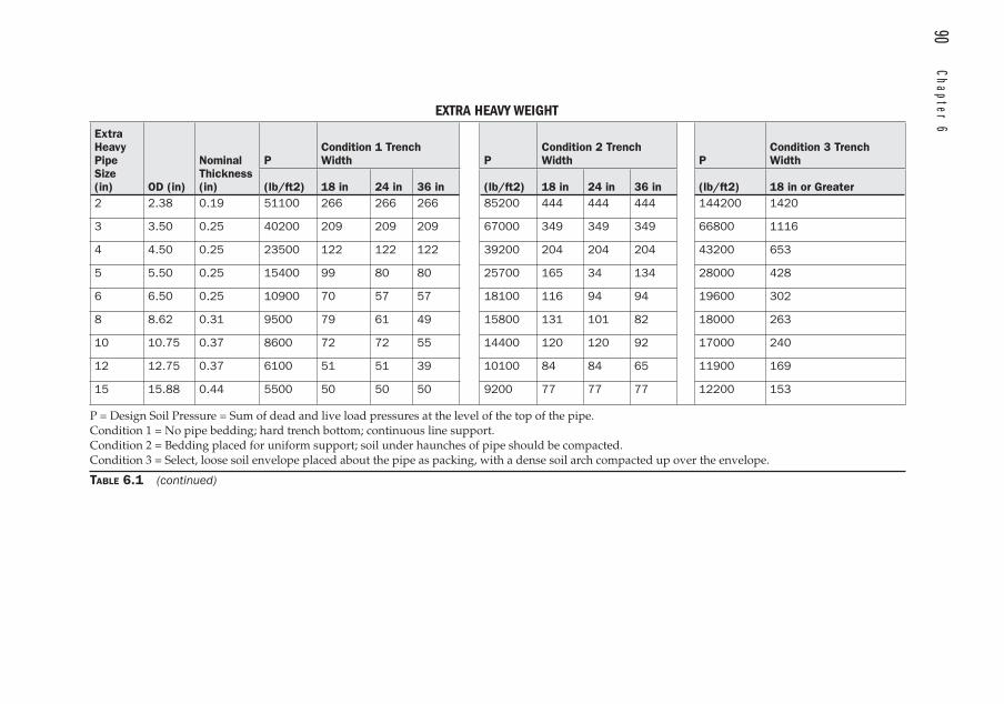
90 Chapter 6
ExtraHeavy PipeSize(in) OD (in)
NominalThickness(in)
PCondition 1 Trench Width P
Condition 2 Trench Width P
Condition 3 Trench Width
(lb/ft2) 18 in 24 in 36 in (lb/ft2) 18 in 24 in 36 in (lb/ft2) 18 in or Greater2 2.38 0.19 51100 266 266 266 85200 444 444 444 144200 1420
3 3.50 0.25 40200 209 209 209 67000 349 349 349 66800 1116
4 4.50 0.25 23500 122 122 122 39200 204 204 204 43200 653
5 5.50 0.25 15400 99 80 80 25700 165 34 134 28000 428
6 6.50 0.25 10900 70 57 57 18100 116 94 94 19600 302
8 8.62 0.31 9500 79 61 49 15800 131 101 82 18000 263
10 10.75 0.37 8600 72 72 55 14400 120 120 92 17000 240
12 12.75 0.37 6100 51 51 39 10100 84 84 65 11900 169
15 15.88 0.44 5500 50 50 50 9200 77 77 77 12200 153
P = Design Soil Pressure = Sum of dead and live load pressures at the level of the top of the pipe.Condition 1 = No pipe bedding; hard trench bottom; continuous line support.Condition 2 = Bedding placed for uniform support; soil under haunches of pipe should be compacted.Condition 3 = Select, loose soil envelope placed about the pipe as packing, with a dense soil arch compacted up over the envelope.
TABLE 6.1 (continued)
EXTRA HEAVY WEIGHT
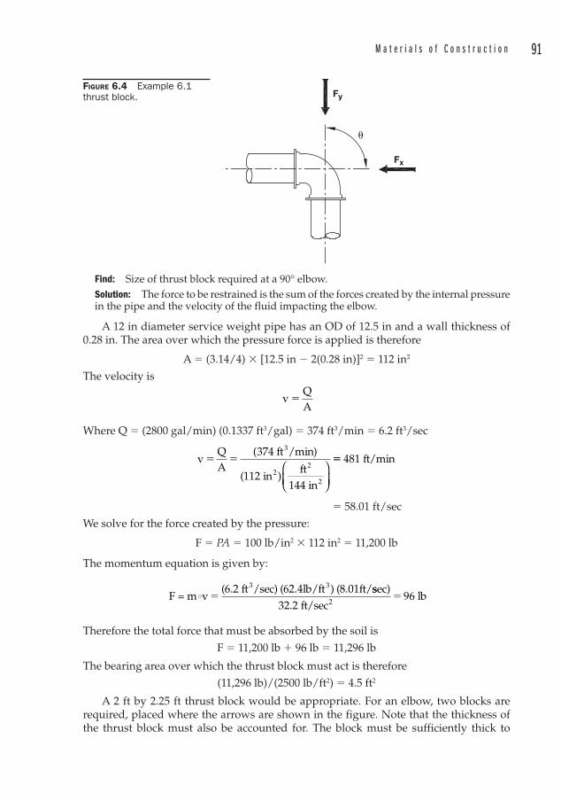
M a t e r i a l s o f C o n s t r u c t i o n 91
Find: Size of thrust block required at a 90° elbow.Solution: The force to be restrained is the sum of the forces created by the internal pressure in the pipe and the velocity of the fluid impacting the elbow.
A 12 in diameter service weight pipe has an OD of 12.5 in and a wall thickness of 0.28 in. The area over which the pressure force is applied is therefore
A � (3.14/4) � [12.5 in � 2(0.28 in)]2 � 112 in2
The velocity is
vQA
�
Where Q � (2800 gal/min) (0.1337 ft3/gal) � 374 ft3/min � 6.2 ft3/sec
vQA
374 ft /min)
(112 inft
144 in
3
22
2
� �(
)⎛
⎝⎜⎞
⎠⎟
�� 481 ft/min
� 58.01 ft/sec
We solve for the force created by the pressure:
F � PA � 100 lb/in2 � 112 in2 � 11,200 lb
The momentum equation is given by:
F = m v(6.2 ft /sec) (62.4lb/ft ) (8.01ft/3 3
i �ssec)
32.2 ft/sec96 lb
2�
Therefore the total force that must be absorbed by the soil is
F � 11,200 lb � 96 lb � 11,296 lb
The bearing area over which the thrust block must a ct is therefore
(11,296 lb)/(2500 lb/ft2) � 4.5 ft2
A 2 ft by 2.25 ft thrust block would be appropriate. For an elbow, two blocks are required, placed where the arrows are shown in the figure. Note that the thickness of the thrust block must also be accounted for. The block must be sufficiently thick to
Fy
Fx
�
FIGURE 6.4 Example 6.1 thrust block.
92 C h a p t e r 6
withstand the compressive force applied without shearing (reinforcing may be required). The calculation currently makes no allowance for water hammer loads, which may increase the force substantially. Finally, there is often very little care paid to thrust blocks during the construction phase. Forms are rarely used. Instead, a hole is dug, a pile of concrete is poured, the hole is covered, and the pipe very often leaks. The surface of the thrust block that bears against the soil should be flat.
Any time you specify a thrust block, great care must be taken in the field to ensure that the thrust block will satisfy the requirements. Field inspections are advisable. In lieu of this, a better choice will be restrained joints designed to accommodate the thrust loads.
Ductile Iron PipeDucti le iron (DI) pipe was developed in 1948, and soon replaced cast iron p ipe in pressure applications. The metallographic structure of ductile iron is such that the graphite exists in the form of nodules. These compact nodules do not interrupt the metallurgical matrix like the graphite flakes in cast iron. The result is a material that is stronger and tougher than cast iron.
ApplicationsLike cast iron, ductile iron is used for sewage service. But it finds additional use in liquid service; especially for water, and especially potable water.
Applicable SpecificationsASME B16.42 Ductile Iron Pipe Flanges and Flanged Fittings, Classes 150
and 300
AWWA C104/A21.4 Cement-Mortar Lining for Ductile-Iron Pipe and Fittings for Water
ASTM A716 Ductile Iron Culvert Pipe
ASTM A746 Ductile Iron Gravity Sewer Pipe
AWWA C105/A21.5 Polyethylene Encasement for Ductile-Iron Pipe Systems
AWWA C110/A21.10 Ductile-Iron and Gray-Iron Fittings for Water
AWWA C111/A21.11 Rubber-Gasket Joints for Ductile-Iron Pressure Pipe and Fittings
AWWA C115/A21.15 Flanged Ductile-Iron Pipe with Ductile-Iron or Gray-Iron Threaded Flanges
AWWA C116/A21.16 Protective Fusion-Bonded Epoxy Coatings Int. & Ext. Surf. Ductile-Iron/Gray-Iron Fittings
AWWA C150/A21.50 Thickness Design of Ductile-Iron Pipe
AWWA C151/A21.51 Ductile-Iron Pipe, Centrifugally Cast, for Water or Other Liquids
AWWA C153/A21.53 Ductile-Iron Compact Fittings for Water Service
M a t e r i a l s o f C o n s t r u c t i o n 93
Manufacture of DI PipeDuctile iron pipe is manufactured in the same way as cast iron pipe; that is, using a centrifugal casting process to form the lengths of pipe.
Ductile iron pipe is available in five pressure classes, defined as the rated working pressure of the pipe, based on a minimum yield strength of 42,000 psi and a 2.0 safety factor which is applied to the working pressure plus a surge pressure of 100 psi.
When DI pipe was introduced, the outside diameters of the sizes between 4 and 48 in inclusive were selected to be identical to that of cast iron pipe to make the transition to the new material easier. Accessories and fittings were then compatible.
Example 6.2Given: 12 in diameter DI pipe at 350 psi working pressure
100 psi surge pressure42,000 psi yield stress
Find: Required wall thickness using a factor of safety of 2
By Barlow’s formula,
T � PD/2Swhere
T � Wall thickness P � Pressure D � Outside diameter S � Yield stress
Then T � (350 psi � 100 psi)(13.20 in) / 2 (42,000 psi)
� 0.071 in
Next we apply the safety factor
T � 2 � 0.071 in � 0.14 in
DI pipe manufacturers add both a “service allowance” and a casting tolerance to this thickness to arrive at the commercial wall thickness . The service allowance is 0.08 in. The casting tolerances are given in Table 6.2 as 0.06 in for this diameter of pipe.
Adding the calculated wall thickness to the service allowance and the casting tolerance yields a commercial wall thickness of
t � 0.14 in � 0.08 in � 0.06 in � 0.28 in
which is the value shown in Table 6.3 for the nominal wall thickness of a 12 in diameter Pressure Class 350 DI pipe.
There are 12 standard wall thickness classes for DI pipe. These classes are analogous to “schedules” or “weights” that are used for steel pipe. The DI pipe classes are divided into two categories:
1. The Pressure Class is named after the working pressure of the pipe, as shown in the example above. It allows for a pressure surge of 100 psi above the working pressure, and includes a yield stress of 42,000 psi for the DI material, a factor of safety of 2, and also the service allowance and casting tolerances described in the above example.
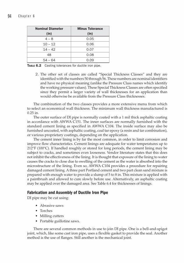
94 C h a p t e r 6
2. The other set of classes are called “Special Thickness Classes” and they are identified with the numbers 50 through 56. These numbers are nominal identifiers and have no physical meaning (unlike the Pressure Class names which identify the working pressure values). These Special Thickness Classes are often specified since they permit a larger variety of wall thicknesses for an application than would otherwise be available from the Pressure Class thicknesses.
The combination of the two classes provides a more extensive menu from which to select an economical wall thickness . The minimum wall thickness manufactured is 0.25 in.
The outer surface of DI pipe is normally coated with a 1 mil thick asphaltic coating in accordance with AWWA C151. The inner surfaces are normally furnished with the standard cement lining as specified in AWWA C104. The inside surface may also be furnished uncoated, with asphaltic coating, coal tar epoxy (a resin and tar combination), or various proprietary coatings, depending on the application.
The cement inner lining is by far the most common, in order to limit corrosion and improve flow characteristics. Cement linings are adequate for water temperatures up to 212°F (100°C). If handled roughly or stored for long periods, the cement lining may be subject to cracks, and sometimes even looseness. Vendor literature states that this does not inhibit the effectiveness of the lining. It is thought that exposure of the lining to water causes the cracks to close due to swelling of the cement as the water is absorbed into the microstructure of the lining. Even so, AWWA C104 provides a procedure for repairing damaged cement lining. A three part Portland cement and two part clean sand mixture is prepared with enough water to provide a slump of 5 to 8 in. This mixture is applied with a paintbrush and allowed to cure slowly before use. Alternatively, an asphaltic coating may be applied over the damaged area. See Table 6.4 for thicknesses of linings.
Fabrication and Assembly of Ductile Iron Pipe DI pipe may be cut using:
• Abrasive saws• Torches• Milling cutters• Portable guillotine saws.
There are several common methods in use to join DI pipe. One is a bell-and-spigot joint, which, like some cast iron pipe, uses a flexible gasket to provide the seal. Another method is the use of flanges. Still another is the mechanical joint.
Nominal Diameter(in)
Minus Tolerance(in)
4 – 8 0.05
10 – 12 0.06
14 – 42 0.07
48 0.08
54 – 64 0.09
TABLE 6.2 Casting tolerances for ductile iron pipe.
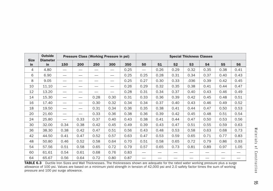
Materials of Construction
95
Sizein
OutsideDiameter
in
Pressure Class (Working Pressure in psi) Special Thickness Classes
150 200 250 300 350 50 51 52 53 54 55 56 4 4.80 — — — — 0.25 — 0.26 0.29 0.32 0.35 0.38 0.41
6 6.90 — — — — 0.25 0.25 0.28 0.31 0.34 0.37 0.40 0.43
8 9.05 — — — — 0.25 0.27 0.30 0.33 .036 0.39 0.42 0.45
10 11.10 — — — — 0.26 0.29 0.32 0.35 0.38 0.41 0.44 0.47
12 13.20 — — — — 0.28 0.31 0.34 0.37 0.40 0.43 0.46 0.49
14 15.30 — — 0.28 0.30 0.31 0.33 0.36 0.39 0.42 0.45 0.48 0.51
16 17.40 — — 0.30 0.32 0.34 0.34 0.37 0.40 0.43 0.46 0.49 0.52
18 19.50 — — 0.31 0.34 0.36 0.35 0.38 0.41 0.44 0.47 0.50 0.53
20 21.60 — — 0.33 0.36 0.38 0.36 0.39 0.42 0.45 0.48 0.51 0.54
24 25.80 — 0.33 0.37 0.40 0.43 0.38 0.41 0.44 0.47 0.50 0.53 0.56
30 32.00 0.34 0.38 0.42 0.45 0.49 0.39 0.43 0.47 0.51 0.55 0.59 0.63
36 38.30 0.38 0.42 0.47 0.51 0.56 0.43 0.48 0.53 0.58 0.63 0.68 0.73
42 44.50 0.41 0.47 0.52 0.57 0.63 0.47 0.53 0.59 0.65 0.71 0.77 0.83
48 50.80 0.46 0.52 0.58 0.64 0.70 0.51 0.58 0.65 0.72 0.79 0.86 0.93
54 57.56 0.51 0.58 0.65 0.72 0.79 0.57 0.65 0.73 0.81 0.89 0.97 1.05
60 61.61 0.54 0.61 0.68 0.76 0.83 — — — — — — —
64 65.67 0.56 0.64 0.72 0.80 0.87 — — — — — — —TABLE 6.3 Ductile Iron Sizes and Wall Thicknesses. The thicknesses shown are adequate for the rated water working pressure plus a surge allowance of 100 psi. Values are based on a minimum yield strength in tension of 42,000 psi and 2.0 safety factor times the sum of working pressure and 100 psi surge allowance.
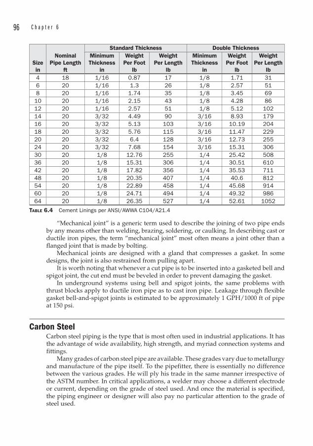
96 C h a p t e r 6
“Mechanical joint” is a generic term used to describe the joining of two pipe ends by any means other than welding, brazing, soldering, or caulking. In describing cast or ductile iron pipes, the term “mechanical joint” most often means a joint other than a flanged joint that is made by bolting.
Mechanical joints are designed with a gland that compresses a gasket. In some designs, the joint is also restrained from pulling apart.
It is worth noting that whenever a cut pipe is to be inserted into a gasketed bell and spigot joint, the cut end must be beveled in order to prevent damaging the gasket.
In underground systems using bell and spigot joints, the same problems with thrust blocks apply to ductile iron pipe as to cast iron pipe. Leakage through flexible gasket bell-and-spigot joints is estimated to be approximately 1 GPH/1000 ft of pipe at 150 psi.
Carbon SteelCarbon steel piping is the type that is most often used in industrial applications. It has the advantage of wide availability, high strength, and myriad connection systems and fittings.
Many grades of carbon steel pipe are available. These grades vary due to metallurgy and manufacture of the pipe itself. To the pipefitter, there is essentially no difference between the various grades. He will ply his trade in the same manner irrespective of the ASTM number. In critical applications, a welder may choose a different electrode or current, depending on the grade of steel used. And once the material is specified, the piping engineer or designer will also pay no particular attention to the grade of steel used.
Sizein
NominalPipe Length
ft
Standard Thickness Double ThicknessMinimumThickness
in
WeightPer Foot
lb
WeightPer Length
lb
MinimumThickness
in
WeightPer Foot
lb
WeightPer Length
lb4 18 1/16 0.87 17 1/8 1.71 316 20 1/16 1.3 26 1/8 2.57 518 20 1/16 1.74 35 1/8 3.45 6910 20 1/16 2.15 43 1/8 4.28 8612 20 1/16 2.57 51 1/8 5.12 10214 20 3/32 4.49 90 3/16 8.93 17916 20 3/32 5.13 103 3/16 10.19 20418 20 3/32 5.76 115 3/16 11.47 22920 20 3/32 6.4 128 3/16 12.73 25524 20 3/32 7.68 154 3/16 15.31 30630 20 1/8 12.76 255 1/4 25.42 50836 20 1/8 15.31 306 1/4 30.51 61042 20 1/8 17.82 356 1/4 35.53 71148 20 1/8 20.35 407 1/4 40.6 81254 20 1/8 22.89 458 1/4 45.68 91460 20 1/8 24.71 494 1/4 49.32 98664 20 1/8 26.35 527 1/4 52.61 1052
TABLE 6.4 Cement Linings per ANSI/AWWA C104/A21.4
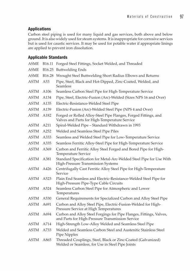
M a t e r i a l s o f C o n s t r u c t i o n 97
ApplicationsCarbon steel piping is used for many liquid and gas services, both above and below ground. It is also widely used for steam systems. It is inappropriate for corrosive services but is used for caustic services. It may be used for potable water if appropriate linings are applied to prevent iron dissolution.
Applicable StandardsASME B16.11 Forged Steel Fittings, Socket Welded, and Threaded
ASME B16.25 Buttwelding Ends
ASME B16.28 Wrought Steel Buttwelding Short Radius Elbows and Returns
ASTM A53 Pipe, Steel, Black and Hot-Dipped, Zinc-Coated, Welded, and Seamless
ASTM A106 Seamless Carbon Steel Pipe for High-Temperature Service
ASTM A134 Pipe, Steel, Electric-Fusion (Arc)-Welded (Sizes NPS 16 and Over)
ASTM A135 Electric-Resistance-Welded Steel Pipe
ASTM A139 Electric-Fusion (Arc)-Welded Steel Pipe (NPS 4 and Over)
ASTM A182 Forged or Rolled Alloy-Steel Pipe Flanges, Forged Fittings, and Valves and Parts for High-Temperature Service
ASTM A211 Spiral-Welded Pipe – Standard Withdrawn in 1993
ASTM A252 Welded and Seamless Steel Pipe Piles
ASTM A333 Seamless and Welded Steel Pipe for Low-Temperature Service
ASTM A335 Seamless Ferritic Alloy-Steel Pipe for High-Temperature Service
ASTM A369 Carbon and Ferritic Alloy Steel Forged and Bored Pipe for High-Temperature Service
ASTM A381 Standard Specification for Metal-Arc-Welded Steel Pipe for Use With High-Pressure Transmission Systems
ASTM A426 Centrifugally Cast Ferritic Alloy Steel Pipe for High-Temperature Service
ASTM A523 Plain End Seamless and Electric-Resistance-Welded Steel Pipe for High-Pressure Pipe-Type Cable Circuits
ASTM A524 Seamless Carbon Steel Pipe for Atmospheric and Lower Temperatures
ASTM A530 General Requirements for Specialized Carbon and Alloy Steel Pipe
ASTM A691 Carbon and Alloy Steel Pipe, Electric-Fusion-Welded for High-Pressure Service at High Temperatures
ASTM A694 Carbon and Alloy Steel Forgings for Pipe Flanges, Fittings, Valves, and Parts for High-Pressure Transmission Service
ASTM A714 High-Strength Low-Alloy Welded and Seamless Steel Pipe
ASTM A733 Welded and Seamless Carbon Steel and Austenitic Stainless Steel Pipe Nipples
ASTM A865 Threaded Couplings, Steel, Black or Zinc-Coated (Galvanized) Welded or Seamless, for Use in Steel Pipe Joints
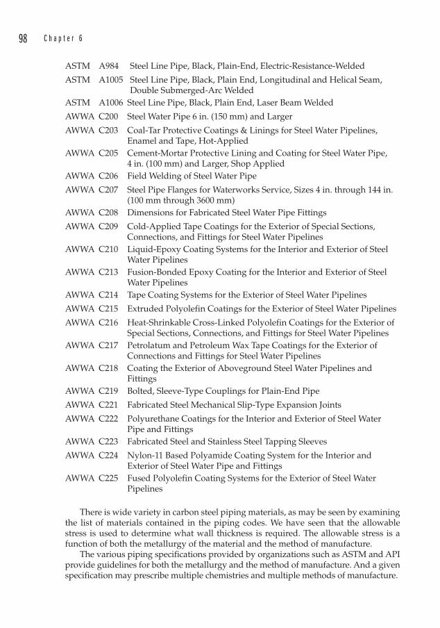
98 C h a p t e r 6
ASTM A984 Steel Line Pipe, Black, Plain-End, Electric-Resistance-Welded
ASTM A1005 Steel Line Pipe, Black, Plain End, Longitudinal and Helical Seam, Double Submerged-Arc Welded
ASTM A1006 Steel Line Pipe, Black, Plain End, Laser Beam Welded
AWWA C200 Steel Water Pipe 6 in. (150 mm) and Larger
AWWA C203 Coal-Tar Protective Coatings & Linings for Steel Water Pipelines, Enamel and Tape, Hot-Applied
AWWA C205 Cement-Mortar Protective Lining and Coating for Steel Water Pipe, 4 in. (100 mm) and Larger, Shop Applied
AWWA C206 Field Welding of Steel Water Pipe
AWWA C207 Steel Pipe Flanges for Waterworks Service, Sizes 4 in. through 144 in. (100 mm through 3600 mm)
AWWA C208 Dimensions for Fabricated Steel Water Pipe Fittings
AWWA C209 Cold-Applied Tape Coatings for the Exterior of Special Sections, Connections, and Fittings for Steel Water Pipelines
AWWA C210 Liquid-Epoxy Coating Systems for the Interior and Exterior of Steel Water Pipelines
AWWA C213 Fusion-Bonded Epoxy Coating for the Interior and Exterior of Steel Water Pipelines
AWWA C214 Tape Coating Systems for the Exterior of Steel Water Pipelines
AWWA C215 Extruded Polyolefin Coatings for the Exterior of Steel Water Pipelines
AWWA C216 Heat-Shrinkable Cross-Linked Polyolefin Coatings for the Exterior of Special Sections, Connections, and Fittings for Steel Water Pipelines
AWWA C217 Petrolatum and Petroleum Wax Tape Coatings for the Exterior of Connections and Fittings for Steel Water Pipelines
AWWA C218 Coating the Exterior of Aboveground Steel Water Pipelines and Fittings
AWWA C219 Bolted, Sleeve-Type Couplings for Plain-End Pipe
AWWA C221 Fabricated Steel Mechanical Slip-Type Expansion Joints
AWWA C222 Polyurethane Coatings for the Interior and Exterior of Steel Water Pipe and Fittings
AWWA C223 Fabricated Steel and Stainless Steel Tapping Sleeves
AWWA C224 Nylon-11 Based Polyamide Coating System for the Interior and Exterior of Steel Water Pipe and Fittings
AWWA C225 Fused Polyolefin Coating Systems for the Exterior of Steel Water Pipelines
There is wide variety in carbon steel piping materials, as may be seen by examining the list of materials contained in the piping codes. We have seen that the allowable stress is used to determine what wall thickness is required. The allowable stress is a function of both the metallurgy of the material and the method of manufacture.
The various piping specifications provided by organizations such as ASTM and API provide guidelines for both the metallurgy and the method of manufacture. And a given specification may prescribe multiple chemistries and multiple methods of manufacture.
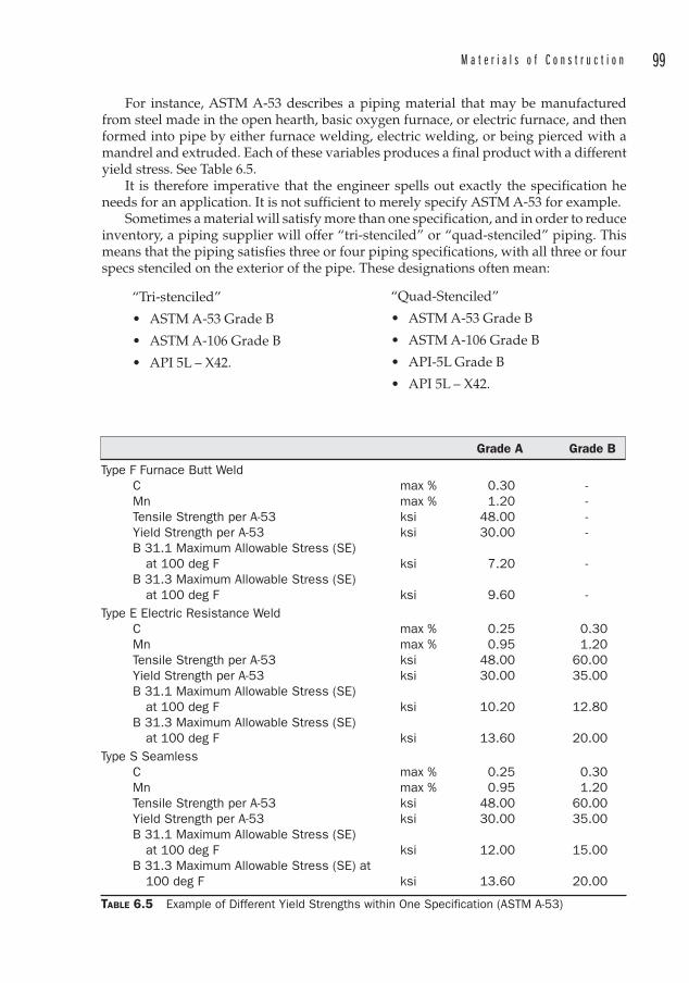
M a t e r i a l s o f C o n s t r u c t i o n 99
For instance, ASTM A-53 describes a piping material that may be manufactured from steel made in the open hearth, basic oxygen furnace, or electric furnace, and then formed into pipe by either furnace welding, electric welding, or being pierced with a mandrel and extruded. Each of these variables produces a final product with a different yield stress. See Table 6.5.
It is therefore imperative that the engineer spells out exactly the specification he needs for an application. It is not sufficient to merely specify ASTM A-53 for example.
Sometimes a material will satisfy more than one specification, and in order to reduce inventory, a piping supplier will offer “tri-stenciled” or “quad-stenciled” piping. This means that the piping satisfies three or four piping specifications, with all three or four specs stenciled on the exterior of the pipe. These designations often mean:
“Tri-stenciled”
• ASTM A-53 Grade B
• ASTM A-106 Grade B
• API 5L – X42.
Grade A Grade B
Type F Furnace Butt Weld C max % 0.30 - Mn max % 1.20 - Tensile Strength per A-53 ksi 48.00 - Yield Strength per A-53 ksi 30.00 - B 31.1 Maximum Allowable Stress (SE) at 100 deg F ksi 7.20 - B 31.3 Maximum Allowable Stress (SE) at 100 deg F ksi 9.60 -Type E Electric Resistance Weld C max % 0.25 0.30 Mn max % 0.95 1.20 Tensile Strength per A-53 ksi 48.00 60.00 Yield Strength per A-53 ksi 30.00 35.00 B 31.1 Maximum Allowable Stress (SE) at 100 deg F ksi 10.20 12.80 B 31.3 Maximum Allowable Stress (SE) at 100 deg F ksi 13.60 20.00Type S Seamless C max % 0.25 0.30 Mn max % 0.95 1.20 Tensile Strength per A-53 ksi 48.00 60.00 Yield Strength per A-53 ksi 30.00 35.00 B 31.1 Maximum Allowable Stress (SE) at 100 deg F ksi 12.00 15.00 B 31.3 Maximum Allowable Stress (SE) at 100 deg F ksi 13.60 20.00
TABLE 6.5 Example of Different Yield Strengths within One Specification (ASTM A-53)
“Quad-Stenciled”
• ASTM A-53 Grade B
• ASTM A-106 Grade B
• API-5L Grade B
• API 5L – X42.
100 C h a p t e r 6
But it is important to note that designations such as tri-stenciled or quad-stenciled may include different specs than those noted above. The best way to proceed is to specify the exact specification that is required.
Manufacture of Carbon Steel PipeSeamless PipeSeamless pipe is produced by heating a round billet or square bloom of steel, and then piercing it with a bullet-shaped piercer, over which the steel is stretched. This is followed by another piercer that opens the hole even more and further elongates the hollow cylinder. A series of straightening rollers, sizing rollers, and heating, cooling, and inspection processes results in a seamless pipe that may now be cut to length and end finished. The final product is hydrostatically tested, inspected, coated if required, and stenciled with the specification.
Because it is a homogeneous substance with no weld stresses, seamless pipe is the strongest variety. For example, the maximum allowable stresses are higher for ASTM Type A-53 Type S (Seamless) than for any of the other varieties of A-53.
The piercing of a round billet is a process that incredibly was first performed in 1845, but proved too technically challenging to produce long lengths of pipe until about 1895.
Electric Resistance Weld (ERW) Pipe ERW pipe is made from coils that are cupped longitudinally by forming rolls and a fin pass section of rolls that brings the ends of the coil together to form a cylinder. These ends are passed through a high frequency welder which heats the steel to 2600°F and squeezes the ends together to form a fusion weld. The weld is heat treated to remove welding stresses and the pipe is cooled, sized to the proper OD, straightened, and cut to length.
There is an optional process that can also be employed to size the pipe while at the same time increasing the transverse yield strength. Incredibly, this process involves hydraulically expanding the pipe. The ends are sealed, and water is forced into the pipe at a pressure high enough to plastically deform the steel to the desired OD and wall thickness . This obviously results in a hydrotest of the weld as well, but each length of pipe is also subjected to a separate hydrotest and is then straightened. The welds are ultrasonically tested, the ends are prepared, and the pipe is visually inspected, coated, and stenciled.
Double Submerged Arc Weld (DSAW) PipeDSAW pipe starts with a plate that is edge milled to ensure that the edges to be joined will be parallel. The edges are then crimped upward and a ram forms the plate into a U-shape. Next the U is placed in an “O”-ing press, which completes the cylinder and prepares it for tack welding. The pipe is welded on the inside, then again on the outside. An inspection of the weld follows, and then the pipe is placed into a mechanical expander that plastically deforms the wall in short longitudinal increments to achieve the appropriate diameter. Additional hydrostatic and NDT is next followed by end beveling and an X-ray inspection of each end of the pipe weld. The finished pipe is visually inspected, coated, and stenciled.
Furnace Weld, Butt Weld or Continuous Weld (CW) PipeThese all refer to the same process, and in fact, the term “Furnace Butt Weld” is also synonymous. Steel strip coil (called a “skelp”) is uncoiled and fed into a roller leveler
M a t e r i a l s o f C o n s t r u c t i o n 101
which flattens the steel. An endless strip is created prior to further processing, so the ends of the coil are cut square and welded to the trailing end of the preceding coil. The continuous strip enters a furnace where it is heated to approximately 2450°F (1343°C). The edge of the strip is raised to approximately 2600°F (1427°C) by an oxygen lance (nozzle) as it exits the furnace. Forming rolls gradually bend the strip into a circle where a set of rollers welds the seam using the heat contained in the strip and the pressure exerted by the welding rollers. The pipe OD is reduced, and the wall thickness is achieved in a stretching mill. A saw cuts the pipe to length, and the pipe enters a sizing mill that reduces the pipe to the final OD. The pipe is straightened, end finished, hydrotested, coated, stenciled, and inspected.
Spiral-Welded PipeASTM A211 was a specification for spiral-welded pipe. This specification was withdrawn in 1993. Spiral-welded pipe is currently manufactured to meet the specifications of ASTM A139 or AWWA C200. It is used primarily by utilities for water distribution service.
Spiral-welded pipe is produced from coils of steel that are unwound and flattened. The flattened strip is formed by angled rollers into a cylinder of the desired diameter. Interior and exterior submerged arc welds seal the spiral seam. At the end of the coil, a new coil is butt welded to the trailing edge of the pipe, forming a cross seam. The pipe is cut to length and the ends are beveled if required.
Available joints for this type of pipe include butt weld, lap weld, and rubber gasketed joints. The lap weld and rubber gasketed joints require a bell to be formed on one end of the pipe. This is created by the manufacturer with a hydraulic expander. After forming the ends, the pipes are hydrostatically tested and then lined with cement. The pipe is next heated to eliminate moisture, and the exterior is blasted to prepare it for the application of an exterior coating.The coating consists of a primer or adhesive, followed by a dielectric tape, and finally a polyethylene wrap.
Sizes of spiral-welded pipe are available from 24 to 144 in, and wall thicknesses up to 1 in.
Wall Thicknesses of Carbon Steel PipeCarbon steel piping is described by the nominal diameter and the “weight” or “schedule. ” The weight or schedule is merely a description of the wall thickness .
As with the DI pressure classes, the carbon steel pipe schedules have evolved over the years into what amounts to a menu of diameters and wall thicknesses that have little to do with either the actual diameters or the wall thicknesses. Everything about these schedules must be considered “nominal.” And the engineer who must perform field measurements of existing installations would be well-advised to either memorize the outside diameters of some of the more common pipes, or to carry with him a copy of the schedules. See Appendix 1 for carbon steel pipe data.
The wall thicknesses known as Standard, Extra Strong (XS), and Double Extra Strong (XXS) are from an older system of describing wall thickness known as Iron Pipe Size (IPS). This system has carried over into the relatively newer system, called the Nominal Pipe Size (NPS), and many (but not all) of the old IPS sizes are duplicated within the NPS schedules:
• Standard is identical to Schedule 40 up to and including 10 in. Starting at 12 in, the wall thickness of Standard pipe remains at 0.375 in.
102 C h a p t e r 6
• Extra Strong is identical to Schedule 80 up to and including 8 in. Starting at 8 in, the wall thickness of XS pipe remains at 0.500 in.
• Double Extra Strong has no related schedule . It is thicker than Schedule 160 up to 6 in diameter, and starting at 8 in diameter it is thinner than Schedule 160.
The NPS system is used throughout North America and the United Kingdom. Europe also uses the same schedules, however they are referred to as the Diameter Nominal (DN) system, and they are identified by a metric approximation of the nominal diameter . Thus, a 1 in pipe specified for use in Canada may be specified in the European Union as DN 25. DN pipe is sometimes also referred to as DIN or ISO pipe.
Not all of the schedules are commercially available in every pipe diameter. Some schedules are not produced, and some are produced only if a minimum tonnage is ordered.
This is seldom a problem though, since most of the time the engineer will specify or work in the common schedules:
• 10 or 10S• Standard• 40• XS• 80• 160• XXS
Note that the published wall thicknesses may be 12.5 percent thicker than the actual thickness.
Sizes of Carbon Steel PipeMany specifications for industrial piping limit the sizes to be used on a project. Rarely will any size below 1 in be specified, for instance, since the smaller diameters are more difficult to support, and the difference in cost is negligible.
There is also a prejudice against 1¼ in and 2½ in pipe in industrial projects due to the costs of stocking pipe and fittings that are so close in size to other economical selections. HVAC projects are more apt to use these sizes for hydronic piping.
The availability of fittings and valves is another concern when specifying piping, since any pipe must necessarily mate with fittings. For this reason, 3 ½ in and 5 in diameter is hardly ever specified. As might be expected, 5 in would fill the gap between 4 in and 6 in nicely in terms of flow velocities. But it is never specified for industrial projects.
The suffix “S” on some of the schedules indicates that these are available in corrosion resistant (stainless) steel. Carbon steel is available in Schedule 10 for all sizes except 42 in. This is sometimes useful for low-pressure applications, and finds use in fire protection piping.
Fabrication and Assembly of Carbon Steel PipeCarbon steel piping is cut to length with oxy-fuel torches or abrasive saws. It is joined in several ways:
• Welded• Threaded and Coupled (T&C)
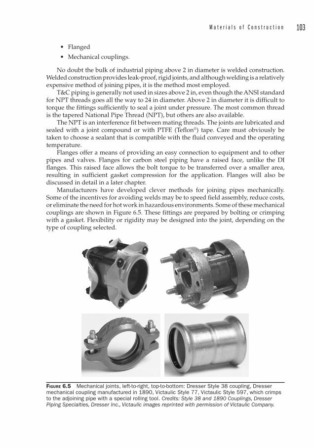
M a t e r i a l s o f C o n s t r u c t i o n 103
• Flanged
• Mechanical couplings.
No doubt the bulk of industrial piping above 2 in diameter is welded construction. Welded construction provides leak-proof, rigid joints, and although welding is a relatively expensive method of joining pipes, it is the method most employed.
T&C piping is generally not used in sizes above 2 in, even though the ANSI standard for NPT threads goes all the way to 24 in diameter. Above 2 in diameter it is difficult to torque the fittings sufficiently to seal a joint under pressure. The most common thread is the tapered National Pipe Thread (NPT), but others are also available.
The NPT is an interference fit between mating threads. The joints are lubricated and sealed with a joint compound or with PTFE (Teflon®) tape. Care must obviously be taken to choose a sealant that is compatible with the fluid conveyed and the operating temperature.
Flanges offer a means of providing an easy connection to equipment and to other pipes and valves. Flanges for carbon steel piping have a raised face, unlike the DI flanges. This raised face allows the bolt torque to be transferred over a smaller area, resulting in sufficient gasket compression for the application. Flanges will also be discussed in detail in a later chapter.
Manufacturers have developed clever methods for joining pipes mechanically. Some of the incentives for avoiding welds may be to speed field assembly, reduce costs, or eliminate the need for hot work in hazardous environments. Some of these mechanical couplings are shown in Figure 6.5. These fittings are prepared by bolting or crimping with a gasket. Flexibility or rigidity may be designed into the joint, depending on the type of coupling selected.
FIGURE 6.5 Mechanical joints, left-to-right, top-to-bottom: Dresser Style 38 coupling, Dresser mechanical coupling manufactured in 1890, Victaulic Style 77, Victaulic Style 597, which crimps to the adjoining pipe with a special rolling tool. Credits: Style 38 and 1890 Couplings, Dresser Piping Specialties, Dresser Inc., Victaulic images reprinted with permission of Victaulic Company.
104 C h a p t e r 6
Stainless Steel PipingStainless steel piping is used whenever corrosion resistance is desired. The addition of chromium is primarily responsible for the corrosion resistant properties of stainless steels. Even though stainless steel exhibits excellent corrosion protection, it would be very unusual to use it in an underground application. A more economical solution would be to use carbon steel with cathodic protection.
Austenitic stainless steels are identified by the 300 series. These alloys contain a maximum of 0.15 percent carbon and a minimum of 16 percent chromium, along with nickel and/or manganese. Austenitic stainless steels are nonmagnetic and have the best high-temperature strengths of all of the stainless steels.
Ferritic stainless steels belong to the 400 series. These steels contain 14 to 27 percent chromium and are magnetic.
Martensitic stainless steels contain 11.5 to 18 percent chromium, and are also magnetic. They are sometimes used in valve components.
Most stainless piping is of the austenitic variety. The most common grades for piping are 304 and 316. There are also special subsets of these which contain lower carbon, making them less susceptible to carbide precipitation. These are designated by the suffix “L.”
Stainless is susceptible to stress corrosion cracking and so exposure to chlorine compounds must be avoided.
ApplicationsStainless steel piping is used wherever iron dissolution cannot be tolerated, as in the production of foods, beverages, and pharmaceuticals. It is often used in uninsulated industrial services to avoid the need to paint the exterior of pipes. The added cost of stainless steel piping can often be offset by the cost of painting and repainting the exterior of carbon steel pipes over the expected lifetime of the installation. The cost of using stainless piping can be reduced further if one is able to take advantage of the 5S or 10S lightweight schedules.
Applicable SpecificationsASTM A312 Seamless, Welded, and Heavily Cold Worked Austenitic Stainless
Steel Pipes
ASTM A358 Electric-Fusion-Welded Austenitic Chromium-Nickel Alloy Steel Pipe for High-Temperature Service
ASTM A376 Seamless Austenitic Steel Pipe for High-Temperature Central-Station Service
ASTM A409 Welded Large Diameter Austenitic Steel Pipe for Corrosive or High-Temperature Service
ASTM A451 Centrifugally Cast Austenitic Steel Pipe for High-Temperature Service
ASTM A790 Seamless and Welded Ferritic /Austenitic Stainless Steel Pipe
ASTM A813 Single- or Double-Welded Austenitic Stainless Steel Pipe
M a t e r i a l s o f C o n s t r u c t i o n 105
ASTM A814 Cold-Worked Welded Austenitic Stainless Steel Pipe
ASTM A872 Centrifugally Cast Ferritic /Austenitic Stainless Steel Pipe for Corrosive Environments
ASTM A928 Ferritic /Austenitic (Duplex) Stainless Steel Pipe Electric Fusion Welded with Addition of Filler Metal
ASTM A943 Spray-Formed Seamless Austenitic Stainless Steel Pipe
ASTM A949 Spray-Formed Seamless Ferritic /Austenitic Stainless Steel Pipe
ASTM A954 Austenitic Chromium-Nickel-Silicon Alloy Steel Seamless and Welded Pipe
ASTM A999 General Requirements for Alloy and Stainless Steel Pipe
AWWA C220 Stainless-Steel Pipe, 1/2 in (13 mm) and Larger
AWWA C226 Stainless Steel Fittings for Waterworks Service, Sizes 1/2 in through 72 in (13 mm through 1800 mm)
Note that in ASME B31.1, Table A-3 references ASTM A213 seamless stainless pipe. This is a specification for boiler and heat exchanger tubes. The corresponding piping specification is ASTM A312.
Manufacture of Stainless Steel PipeAside from differences in the welding procedures, stainless pipe is manufactured similarly to carbon steel pipe.
As noted above, there are special wall thicknesses available in stainless steel piping to reduce the material costs. (A crude rule-of-thumb is that the material cost of stainless steel is three times more than carbon steel.) Manufacturers therefore developed lighter wall thicknesses to make stainless steel more attractive3.
The mill tolerance of 12.5 percent must be applied to stainless steel piping as well as to carbon. Usually, any corrosion allowance can be eliminated in the thickness calculation though, since stainless resists corrosion under most applications.
Fabrication and Assembly of Stainless Steel PipingOne technique that is applied to cutting stainless steel is “air carbon arc gouging.” This technique can be applied to a wide range of metals, but it is often used to quickly cut through stainless steel. An electric arc is generated between a copper-coated carbon electrode and the metal to be cut. This is done using an electric arc welder. When the metal melts at the arc, a jet of air blows the molten metal away. This method removes metal quickly, but it is very noisy due to the high electric current and high-pressure air. The resulting cut is typically very clean and does not result in carbon absorption by the surrounding metal since the molten metal is quickly removed by the air jet. Low air flow can lead to carbon hardening and cracking of the metal in the area of the cut.
Except for different welding procedures, stainless steel piping is fabricated and assembled in much the same way as carbon steel piping. Refer to Table 6.6 for a summary of the various welding procedures.
3 Carbon steel is also available in Schedule 10S.
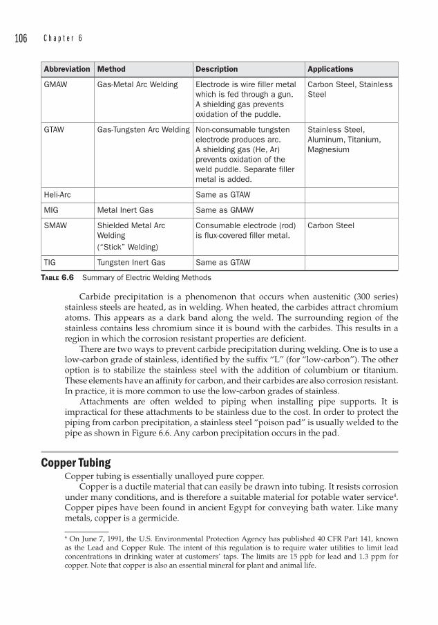
106 C h a p t e r 6
Carbide precipitation is a phenomenon that occurs when austenitic (300 series) stainless steels are heated, as in welding. When heated, the carbides attract chromium atoms. This appears as a dark band along the weld. The surrounding region of the stainless contains less chromium since it is bound with the carbides. This results in a region in which the corrosion resistant properties are deficient.
There are two ways to prevent carbide precipitation during welding. One is to use a low-carbon grade of stainless, identified by the suffix “L” (for “low-carbon”). The other option is to stabilize the stainless steel with the addition of columbium or titanium. These elements have an affinity for carbon, and their carbides are also corrosion resistant. In practice, it is more common to use the low-carbon grades of stainless.
Attachments are often welded to piping when installing pipe supports. It is impractical for these attachments to be stainless due to the cost. In order to protect the piping from carbon precipitation, a stainless steel “poison pad” is usually welded to the pipe as shown in Figure 6.6. Any carbon precipitation occurs in the pad.
Copper Tubing Copper tubing is essentially unalloyed pure copper.
Copper is a ductile material that can easily be drawn into tubing. It resists corrosion under many conditions, and is therefore a suitable material for potable water service4. Copper pipes have been found in ancient Egypt for conveying bath water. Like many metals, copper is a germicide.
4 On June 7, 1991, the U.S. Environmental Protection Agency has published 40 CFR Part 141, known as the Lead and Copper Rule. The intent of this regulation is to require water utilities to limit lead concentrations in drinking water at customers’ taps. The limits are 15 ppb for lead and 1.3 ppm for copper. Note that copper is also an essential mineral for plant and animal life.
Abbreviation Method Description Applications
GMAW Gas-Metal Arc Welding Electrode is wire filler metal which is fed through a gun. A shielding gas prevents oxidation of the puddle.
Carbon Steel, Stainless Steel
GTAW Gas-Tungsten Arc Welding Non-consumable tungsten electrode produces arc. A shielding gas (He, Ar) prevents oxidation of the weld puddle. Separate filler metal is added.
Stainless Steel, Aluminum, Titanium, Magnesium
Heli-Arc Same as GTAW
MIG Metal Inert Gas Same as GMAW
SMAW Shielded Metal Arc Welding(“Stick” Welding)
Consumable electrode (rod) is flux-covered filler metal.
Carbon Steel
TIG Tungsten Inert Gas Same as GTAW
TABLE 6.6 Summary of Electric Welding Methods
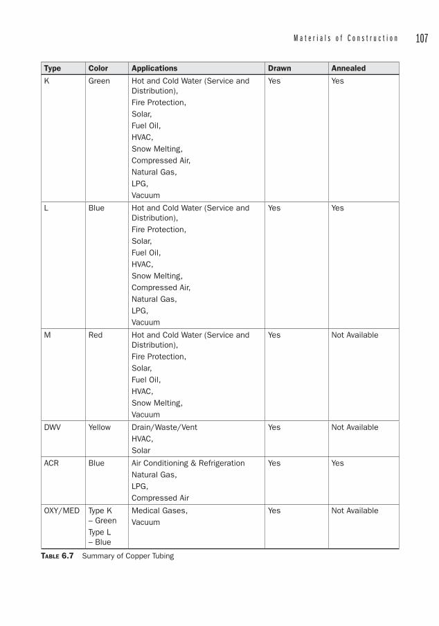
M a t e r i a l s o f C o n s t r u c t i o n 107
Type Color Applications Drawn Annealed
K Green Hot and Cold Water (Service and Distribution),Fire Protection, Solar, Fuel Oil,HVAC,Snow Melting,Compressed Air,Natural Gas,LPG,Vacuum
Yes Yes
L Blue Hot and Cold Water (Service and Distribution),Fire Protection, Solar, Fuel Oil,HVAC,Snow Melting,Compressed Air,Natural Gas,LPG,Vacuum
Yes Yes
M Red Hot and Cold Water (Service and Distribution),Fire Protection, Solar, Fuel Oil,HVAC,Snow Melting,Vacuum
Yes Not Available
DWV Yellow Drain/Waste/VentHVAC,Solar
Yes Not Available
ACR Blue Air Conditioning & RefrigerationNatural Gas,LPG, Compressed Air
Yes Yes
OXY/MED Type K – GreenType L – Blue
Medical Gases,Vacuum
Yes Not Available
TABLE 6.7 Summary of Copper Tubing
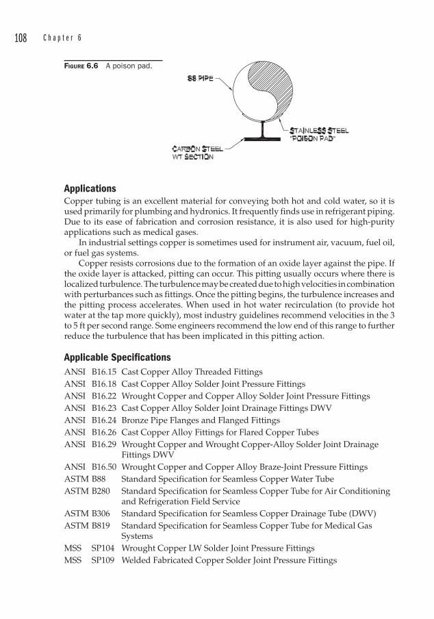
108 C h a p t e r 6
ApplicationsCopper tubing is an excellent material for conveying both hot and cold water, so it is used primarily for plumbing and hydronics. It frequently finds use in refrigerant piping. Due to its ease of fabrication and corrosion resistance, it is also used for high-purity applications such as medical gases.
In industrial settings copper is sometimes used for instrument air, vacuum, fuel oil, or fuel gas systems.
Copper resists corrosions due to the formation of an oxide layer against the pipe. If the oxide layer is attacked, pitting can occur. This pitting usually occurs where there is localized turbulence. The turbulence may be created due to high velocities in combination with perturbances such as fittings. Once the pitting begins, the turbulence increases and the pitting process accelerates. When used in hot water recirculation (to provide hot water at the tap more quickly), most industry guidelines recommend velocities in the 3 to 5 ft per second range. Some engineers recommend the low end of this range to further reduce the turbulence that has been implicated in this pitting action.
Applicable SpecificationsANSI B16.15 Cast Copper Alloy Threaded FittingsANSI B16.18 Cast Copper Alloy Solder Joint Pressure FittingsANSI B16.22 Wrought Copper and Copper Alloy Solder Joint Pressure FittingsANSI B16.23 Cast Copper Alloy Solder Joint Drainage Fittings DWVANSI B16.24 Bronze Pipe Flanges and Flanged FittingsANSI B16.26 Cast Copper Alloy Fittings for Flared Copper TubesANSI B16.29 Wrought Copper and Wrought Copper-Alloy Solder Joint Drainage
Fittings DWVANSI B16.50 Wrought Copper and Copper Alloy Braze-Joint Pressure FittingsASTM B88 Standard Specification for Seamless Copper Water TubeASTM B280 Standard Specification for Seamless Copper Tube for Air Conditioning
and Refrigeration Field ServiceASTM B306 Standard Specification for Seamless Copper Drainage Tube (DWV)ASTM B819 Standard Specification for Seamless Copper Tube for Medical Gas
SystemsMSS SP104 Wrought Copper LW Solder Joint Pressure FittingsMSS SP109 Welded Fabricated Copper Solder Joint Pressure Fittings
FIGURE 6.6 A poison pad.
M a t e r i a l s o f C o n s t r u c t i o n 109
Manufacture of Copper Tubing Copper is melted in a furnace where the temperature is brought several hundred degrees Fahrenheit above the melting point. Impurities are removed through various slagging techniques, with the result being a pool of 99.9 percent copper. Copper cast into solid billets is pierced with a mandrel in much the same way that seamless carbon steel pipe is produced. Hollow billets and pierced billets are extruded, and then drawn through dies to reduce the outside diameter.
Drawing results in work-hardening. The tubes become stiff, and this as-drawn condition is one of the two tempers available for copper tubing. Alternately, copper tubing is available in a soft annealed condition, usually sold in coils, but also available in straight lengths.
There are six different types of copper tubing, as shown in Table 6.7. Under ASTM B88, the wall thicknesses are described by “type” rather than “schedule. ”
• Type K has the heaviest wall thickness for a given size. The next heaviest is Type L, with Type M being the lightest.5
• Types K, L, M and DWV and Medical Gas (OXY/MED) tubes are specified by nominal diameters, with their actual ODs always 1/8 in larger than the nominal size.
• Type ACR is designated by its actual OD.
• OXY/MED tubing is available in Types K and L, but is manufactured in accordance with ASTM B819.
See Table 6.8 for available copper tubing sizes and wall thicknesses.
Fabrication and Assembly of Copper Tubing Copper tubing may be cut to length with a hacksaw or abrasive saw, but is usually cut with a tubing cutter. These repeatedly score the tube with hardened wheels, displacing the soft copper until the tube is cut all the way through. Cutters are available with small swing radii to permit field cuts in tight quarters.
Copper tubing is joined by soldering, brazing, compression fittings, or grooved-end connections.
Fittings for soldering or brazing are available as either wrought or cast , but wrought fittings are preferred for brazing. The term “wrought” (often misspelled as “wrot” in the trades and catalogs) means “worked,” and these fittings are forged as opposed to being cast. Cast fittings contain copper, tin, lead, and zinc.
Soldered ConnectionsAlso called sweat connections, solder joints are made with a variety of fittings that slip over the OD of the adjoining tube. The small clearance provides a means of filling the annulus with solder using capillary action. Solder can be made to flow up inside a joint.
While lead6 solder is still available, its use in potable water was banned in the United States in 1988. Solder for potable water systems now contains tin and antimony.
5 A useful mnemonic device is “thicK.” The only letter in the word “thick” among K, L, and M is “K,” and this has the thickest wall.6 The chemical symbol for lead is Pb, from the Latin plumbum. This is the word from which “plumber” is derived. Plumber used to mean “lead-worker,” since lead pipes were used extensively in plumbing systems.
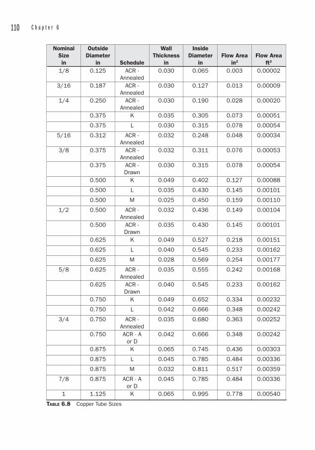
110 C h a p t e r 6
NominalSizein
OutsideDiameter
in Schedule
Wall Thickness
in
InsideDiameter
inFlow Area
in2
Flow Areaft2
1/8 0.125 ACR - Annealed
0.030 0.065 0.003 0.00002
3/16 0.187 ACR - Annealed
0.030 0.127 0.013 0.00009
1/4 0.250 ACR - Annealed
0.030 0.190 0.028 0.00020
0.375 K 0.035 0.305 0.073 0.00051
0.375 L 0.030 0.315 0.078 0.00054
5/16 0.312 ACR - Annealed
0.032 0.248 0.048 0.00034
3/8 0.375 ACR - Annealed
0.032 0.311 0.076 0.00053
0.375 ACR - Drawn
0.030 0.315 0.078 0.00054
0.500 K 0.049 0.402 0.127 0.00088
0.500 L 0.035 0.430 0.145 0.00101
0.500 M 0.025 0.450 0.159 0.00110
1/2 0.500 ACR - Annealed
0.032 0.436 0.149 0.00104
0.500 ACR - Drawn
0.035 0.430 0.145 0.00101
0.625 K 0.049 0.527 0.218 0.00151
0.625 L 0.040 0.545 0.233 0.00162
0.625 M 0.028 0.569 0.254 0.00177
5/8 0.625 ACR - Annealed
0.035 0.555 0.242 0.00168
0.625 ACR - Drawn
0.040 0.545 0.233 0.00162
0.750 K 0.049 0.652 0.334 0.00232
0.750 L 0.042 0.666 0.348 0.00242
3/4 0.750 ACR - Annealed
0.035 0.680 0.363 0.00252
0.750 ACR - A or D
0.042 0.666 0.348 0.00242
0.875 K 0.065 0.745 0.436 0.00303
0.875 L 0.045 0.785 0.484 0.00336
0.875 M 0.032 0.811 0.517 0.00359
7/8 0.875 ACR - A or D
0.045 0.785 0.484 0.00336
1 1.125 K 0.065 0.995 0.778 0.00540
TABLE 6.8 Copper Tube Sizes
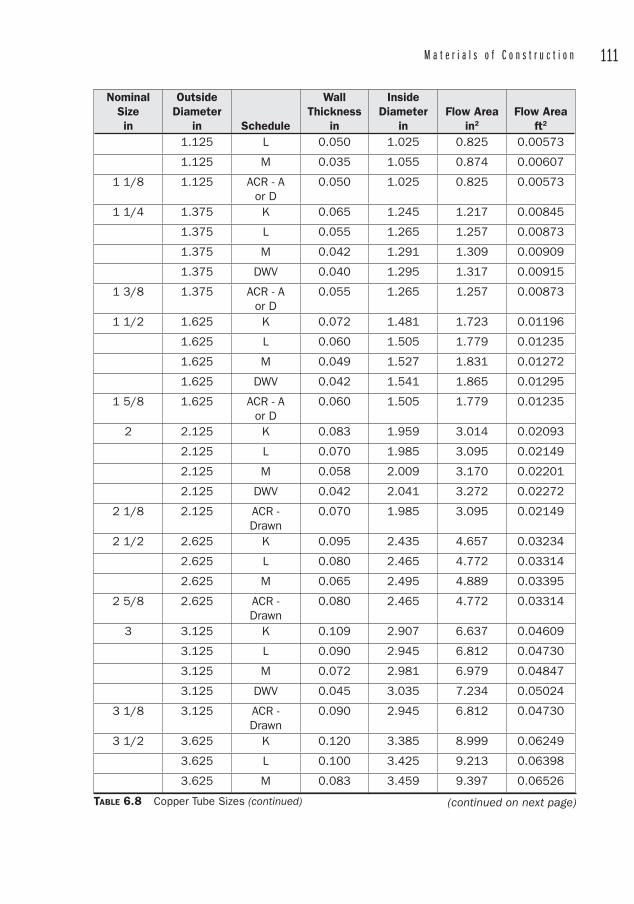
M a t e r i a l s o f C o n s t r u c t i o n 111
NominalSizein
OutsideDiameter
in Schedule
Wall Thickness
in
InsideDiameter
inFlow Area
in2
Flow Areaft2
1.125 L 0.050 1.025 0.825 0.00573
1.125 M 0.035 1.055 0.874 0.00607
1 1/8 1.125 ACR - A or D
0.050 1.025 0.825 0.00573
1 1/4 1.375 K 0.065 1.245 1.217 0.00845
1.375 L 0.055 1.265 1.257 0.00873
1.375 M 0.042 1.291 1.309 0.00909
1.375 DWV 0.040 1.295 1.317 0.00915
1 3/8 1.375 ACR - A or D
0.055 1.265 1.257 0.00873
1 1/2 1.625 K 0.072 1.481 1.723 0.01196
1.625 L 0.060 1.505 1.779 0.01235
1.625 M 0.049 1.527 1.831 0.01272
1.625 DWV 0.042 1.541 1.865 0.01295
1 5/8 1.625 ACR - A or D
0.060 1.505 1.779 0.01235
2 2.125 K 0.083 1.959 3.014 0.02093
2.125 L 0.070 1.985 3.095 0.02149
2.125 M 0.058 2.009 3.170 0.02201
2.125 DWV 0.042 2.041 3.272 0.02272
2 1/8 2.125 ACR - Drawn
0.070 1.985 3.095 0.02149
2 1/2 2.625 K 0.095 2.435 4.657 0.03234
2.625 L 0.080 2.465 4.772 0.03314
2.625 M 0.065 2.495 4.889 0.03395
2 5/8 2.625 ACR - Drawn
0.080 2.465 4.772 0.03314
3 3.125 K 0.109 2.907 6.637 0.04609
3.125 L 0.090 2.945 6.812 0.04730
3.125 M 0.072 2.981 6.979 0.04847
3.125 DWV 0.045 3.035 7.234 0.05024
3 1/8 3.125 ACR - Drawn
0.090 2.945 6.812 0.04730
3 1/2 3.625 K 0.120 3.385 8.999 0.06249
3.625 L 0.100 3.425 9.213 0.06398
3.625 M 0.083 3.459 9.397 0.06526
TABLE 6.8 Copper Tube Sizes (continued) (continued on next page)
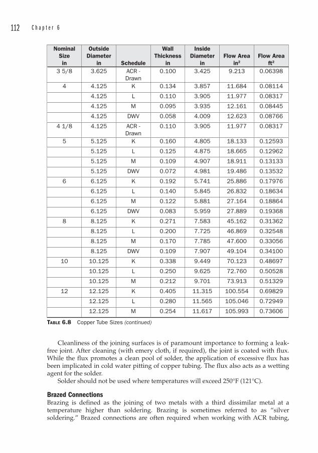
112 C h a p t e r 6
Cleanliness of the joining surfaces is of paramount importance to forming a leak-free joint. After cleaning (with emery cloth, if required), the joint is coated with flux. While the flux promotes a clean pool of solder, the application of excessive flux has been implicated in cold water pitting of copper tubing. The flux also acts as a wetting agent for the solder.
Solder should not be used where temperatures will exceed 250°F (121°C).
Brazed ConnectionsBrazing is defined as the joining of two metals with a third dissimilar metal at a temperature higher than soldering. Brazing is sometimes referred to as “silver soldering.” Brazed connections are often required when working with ACR tubing,
NominalSizein
OutsideDiameter
in Schedule
Wall Thickness
in
InsideDiameter
inFlow Area
in2
Flow Areaft2
3 5/8 3.625 ACR - Drawn
0.100 3.425 9.213 0.06398
4 4.125 K 0.134 3.857 11.684 0.08114
4.125 L 0.110 3.905 11.977 0.08317
4.125 M 0.095 3.935 12.161 0.08445
4.125 DWV 0.058 4.009 12.623 0.08766
4 1/8 4.125 ACR - Drawn
0.110 3.905 11.977 0.08317
5 5.125 K 0.160 4.805 18.133 0.12593
5.125 L 0.125 4.875 18.665 0.12962
5.125 M 0.109 4.907 18.911 0.13133
5.125 DWV 0.072 4.981 19.486 0.13532
6 6.125 K 0.192 5.741 25.886 0.17976
6.125 L 0.140 5.845 26.832 0.18634
6.125 M 0.122 5.881 27.164 0.18864
6.125 DWV 0.083 5.959 27.889 0.19368
8 8.125 K 0.271 7.583 45.162 0.31362
8.125 L 0.200 7.725 46.869 0.32548
8.125 M 0.170 7.785 47.600 0.33056
8.125 DWV 0.109 7.907 49.104 0.34100
10 10.125 K 0.338 9.449 70.123 0.48697
10.125 L 0.250 9.625 72.760 0.50528
10.125 M 0.212 9.701 73.913 0.51329
12 12.125 K 0.405 11.315 100.554 0.69829
12.125 L 0.280 11.565 105.046 0.72949
12.125 M 0.254 11.617 105.993 0.73606
TABLE 6.8 Copper Tube Sizes (continued)

M a t e r i a l s o f C o n s t r u c t i o n 113
since they form stronger joints than soldered connections. Brazing can accommodate operating temperatures as high as 350°F (17°C). The same fittings are used for brazing as for soldering, although wrought fittings are preferred for brazing.
Compression FittingsFlared connections are a type of compression connection most easily made with annealed Type K or L tubing. Types K, L, or M hard temper may also be flared after annealing the end of the tube to be flared.
Because a flared connection is essentially a union with a metal-to-metal seal between the ends of the tubing, it is essential for the end to be squarely cut and free of burrs. A flaring tool shapes a cup on the tube end, and a nut behind the cup tightens into a cone-shape that engages the interior of the flare.
Another type of compression fitting is made with a ferrule that digs into the OD of the tube whenever a compression nut is tightened around it.
No-Solder Push-On JointsRecently introduced as an alternative to soldering are a variety of fittings that join copper tubing by inserting it into the joint. See Figure 6.7. The end of the joint contains a plastic sleeve that fits inside the copper tubing. The fitting itself is a cast copper material that contains a ring of sharp barbs or teeth around its ID. These teeth bite into the OD of the copper tube when inserted. Once inserted, the tubing cannot be removed. If a trial fit-up is required for measuring, a plastic removal sleeve is used to prevent the fitting from permanently attaching to the tubing.
The National Institutes of Health recommends that if copper tubing domestic water lines contain lead solder, they be flushed for a minute or two before using the water to cook with or drink. This is only necessary if they have not been operated for awhile (for instance, overnight). You can tell if the water has been flushed enough by checking its temperature. Stagnant water in cold water pipes will warm up inside the structure. When the water gets colder, you know that you are drawing fresh water from the distribution piping out in the street. This is another reason why you should only use cold water for cooking. Hot water leaches lead faster than cold water does.
FIGURE 6.7 Push-on copper tubing couplings require no soldering skills.
114 C h a p t e r 6
The assembly of copper tubing using these fittings requires no special skills such as soldering. This results in a potential labor savings over construction using sweat fittings. However, the cost of these fittings is considerably more than sweat fittings.
Note that the plastic sleeve inside these fittings reduces the ID of the tubing significantly, so if many of these connections are used in a single run, some restriction of flow may result.
Brass PipeBrass pipe is manufactured from an alloy of 85 percent copper and 15 percent zinc. It is an uncommon piping material, but is sometimes used for potable water pressure pipe where hot work is impractical. It is also sometimes used for drainage due to its ability to resist specific corrosives. Brass pipe may be threaded, flanged, or soldered.
Applicable SpecificationsANSI B16.15 Cast Copper Alloy Threaded FittingsANSI B16.18 Cast Copper Alloy Solder Joint Pressure FittingsANSI B16.24 Bronze Pipe Flanges and Flanged FittingsANSI B16.26 Cast Copper Alloy Fittings for Flared Copper TubesANSI B16.29 Wrought Copper and Wrought Copper-Alloy Solder Joint Drainage
Fittings DWV
Titanium PipingTitanium is often thought to be an exotic material for piping systems, yet it is the ninth most common element in the earth’s crust. Among common piping materials, only iron and aluminum are more abundant. There is approximately six times more titanium present than copper. Titanium resists corrosion, has high strength, and low weight.
ApplicationsTitanium piping is used in the petrochemical, pulp and paper, food processing, and power generation industries. It is compatible with:
• Chlorides• Hydrogen sulfide• Dilute hydrochloric acid• Ammonia• Hydrogen
Applicable SpecificationsASTM B861 Standard Specification for Titanium and Titanium Alloy Seamless Pipe
ASTM B862 Standard Specification for Titanium and Titanium Alloy Welded Pipe
ASTM B363 Standard Specification for Seamless and Welded Unalloyed Titanium and Titanium Alloy Welding Fittings
M a t e r i a l s o f C o n s t r u c t i o n 115
ManufactureTitanium pipe is available as either seamless or welded. Seamless pipe is available in sizes from 1⁄8 to 6 in NPS, and in schedules 10S, 40S, and 80S to match the same wall thicknesses as steel pipe. Welded titanium pipe is available in sizes from ¾ to 24 in NPS, in schedules 10S and 40S.
There are many grades of titanium piping, but the most common is Grade 2. This is an unalloyed grade with a minimum yield strength of 40 ksi and a minimum tensile strength of 50 ksi. Other grades of titanium pipe are Grades 1, 3, 7, and 12.
Fabrication and Assembly of Titanium PipeTitanium piping can be cut with an abrasive wheel. It is welded using the TIG or MIG processes, but the welding process for titanium is sensitive to air currents and contamination more so than for other metals.
Aluminum Piping and Tubing Aluminum is a lightweight metal that is approximately one-third the density of steel. It resists corrosion, and may be alloyed with magnesium, manganese, or silicon.
ApplicationsAluminum piping systems are not very common, but they are sometimes used for pneumatic conveying and compressed gas applications, including enrichment of uranium through centrifugal cascades. It resists corrosion, but is not compatible with acids, mercury, or strong alkalis.
At least one manufacturer has designed a clever aluminum piping system for use in plant compressed air systems. The pipes are joined with a proprietary mechanical coupling which seals the ends together with a sleeve. The advantages are alleged to be low installation cost due to the lightweight of the pipe, ease of completing the joint, and flexibility for changing the configuration. Because aluminum will not corrode, a further advantage over steel is that the airstream remains clean.
One caution regarding compressed air systems is that they are notorious for developing leaks, and even small leaks rob the system of efficiency. The cost to compress air is so high that every leak results in lost energy dollars in a very short time. Therefore, any improvements that can be made to seal a compressed air system will likely offset installation costs over the life of the system. The emphasis should be on providing a leak-free system.
Applicable SpecificationsASTM B210 Standard Specification for Aluminum and Aluminum-Alloy Drawn
Seamless Tubes
ASTM B241 Standard Specification for Aluminum and Aluminum-Alloy Drawn Seamless Pipe and Seamless Extruded Tube
116 C h a p t e r 6
ManufactureSeamless aluminum pipe and tubing is formed by extruding a hollow billet over a mandrel. Seamless tubes may be drawn through a die to achieve closer tolerances on diameter and wall thicknesses.
Non-Heat Treatable AlloysDrawn tube in Alloy 3003 has excellent resistance to chemical corrosion. It has excellent workability and weldability. The 3000 series of alloys contain manganese.
Drawn tube in Alloy 5085 provides high strength after welding. It too has excellent resistance to chemical corrosion. The 5000 series of alloys contain magnesium.
Heat-Treatable AlloysAlloy 6061 is available in both tube and pipe. It is almost twice as strong as Alloy 3003, and has good workability, weldability, and corrosion resistance. The 600 series of alloys contain magnesium and silicon.
Alloy 6063 is also available in both tube and pipe. It is more resistant to corrosion than 6061. It can also be anodized.
The anodization process is usually applied to aluminum, magnesium, zinc, and their alloys. It consists of applying an oxide coating on the surface of the metal in order to impart qualities such as wear resistance or improve the appearance of the metal. Anodizing builds a thicker oxide layer than would otherwise form from simple exposure to air.
Aluminum pipe is available as Schedule 40, in sizes from 1⁄8 to 12 in, and as Schedule 80 in sizes from 1 to 5 in. Tubing is available in sizes ranging from 3⁄16 to 10½ in.
Fabrication and AssemblyBeing a soft metal, aluminum is easily cut with hand or power hacksaws. Abrasive saws are not used on the soft alloys, since they tend to smear the metal rather than cut it.
Joints are brazed or welded using alloy fillers, and although it is weldable, skill is required to produce acceptable joints. Mechanical couplings are also used.
PVC (Polyvinyl Chloride) PipingPVC is a thermoplastic polymer. PVC piping is used in pressure piping as well as in plumbing drainage. It is widely available, relatively inexpensive, and the subject of some controversy over its environmental impact. It is the most widely used material for plastic piping.
The chlorine component of PVC constitutes 57 percent of the weight of the molecule, so less petroleum is required in the production of PVC than in other plastics.
PVC pipe is manufactured from compounds that contain no plasticizers. Plasticizers such as phthalates are known to leach out of the plastic, and have been a health concern due to a link with hormone activity. Because phthalates are not present in PVC pipe, it may be considered inert when exposed to potable water. The controversy surrounding its use is due to the environmental impact of dioxins released during its manufacture and disposal by incineration. Post-consumer recycling of PVC on an industrial scale has been difficult, but recent technologies offer hope for economical recycling with reduced environmental impact. PVC pipe manufacturers claim to recycle nearly 100 percent of waste product.
M a t e r i a l s o f C o n s t r u c t i o n 117
Although there is not a uniform standard for color of PVC piping, the following color scheme generally applies:
• White – Cold water, DWV• Blue – Cold water• Dark Gray – Cold water, industrial• Green – Sewer.
ApplicationsPVC is widely used for cold water pressure piping and DWV piping. It is also used in many industrial applications.
Pipe materials that have a low modulus of elasticity will produce lower surge pressures than materials with higher moduli of elasticity. Therefore, a PVC piping system will generate a lower pressure surge (water hammer) than a carbon steel system (all other things being equal). Joint restraints under pressure surge conditions are always important to consider.
PVC pipe used for potable water distribution must be certified for potable water service.
Though PVC contains stabilizers to help prevent ultraviolet degradation, PVC should be painted with latex paint if it is to be exposed to sunlight, and pipe stored outdoors should be covered with an opaque tarp. Better applications are underground or inside structures. Above ground support of PVC pipe can be costly in order to avoid excessive sagging in between supports.
PVC is not suitable for hot water, since it has a maximum temperature limit of only 140°F (60°C). Being a thermoplastic, the strength drops off quickly as the temperature rises above ambient, and the working pressure must be de-rated for temperatures above 73°F (23°C). See Table 6.9.
PVC is never to be used for compressed gases, nor is it to be tested with gases under pressure.
Applicable SpecificationsASTM D1784 Standard Specification for Rigid Poly(Vinyl Chloride) (PVC )
Compounds and Chlorinated Poly(Vinyl Chloride) (CPVC ) Compounds
ASTM D1785 Standard Specification for Poly(Vinyl Chloride) (PVC ) Plastic Pipe, Schedules 40, 80, and 120
ASTM D2241 Standard Specification for Polyvinyl Chloride Pressure-Rated Pipe (SDR Series)
ASTM D2466 Standard Specification for Poly(Vinyl Chloride) (PVC ) Plastic Pipe Fittings, Schedule 40
ASTM D2467 Standard Specification for Poly(Vinyl Chloride) (PVC ) Plastic Pipe Fittings, Schedule 80
ASTM D2564 Standard Specification for Solvent Cements for Poly(Vinyl Chloride) (PVC ) Plastic Piping Systems
ASTM D2665 Standard Specification for Poly(Vinyl Chloride) (PVC ) Plastic Drain, Waste, and Vent Pipe and Fittings
118 C h a p t e r 6
ASTM D2672 Standard Specification for Joints for IPS PVC Pipe Using Solvent Cement
ASTM D2680 Standard Specification for Acrylonitrile-Butadiene-Styrene (ABS ) and Polyvinyl Chloride (PVC ) Composite Sewer Piping
ASTM D2729 Standard Specification for Poly(Vinyl Chloride) (PVC ) Sewer Pipe and Fittings
ASTM D2855 Standard Practice for Making Solvent-Cemented Joints with Poly(Vinyl Chloride) (PVC ) Pipe and Fittings
ASTM D2949 Standard Specification for 3.25-in Outside Diameter Poly(Vinyl Chloride) (PVC ) Plastic Drain, Waste, and Vent Pipe and Fittings
ASTM D3034 Standard Specification for Type PSM Poly(Vinyl Chloride) (PVC ) Sewer Pipe and Fittings
ASTM F402 Standard Practice for Safe Handling of Solvent Cements, Primers, and Cleaners Used for Joining Thermoplastic Pipe and Fittings
ASTM F679 Standard Specification for Poly(Vinyl Chloride) (PVC ) Large-Diameter Plastic Gravity Sewer Pipe and Fittings
ASTM F758 Standard Specification for Smooth-Wall Poly(Vinyl Chloride) (PVC ) Plastic Underdrain Systems for Highway, Airport, and Similar Drainage
ASTM F949 Standard Specification for Poly(Vinyl Chloride) (PVC ) Corrugated Sewer Pipe With a Smooth Interior and Fittings
AWWA C605 Underground Installation of Polyvinyl Chloride (PVC ) Pressure Pipe and Fittings for Water
AWWA C900 Polyvinyl Chloride (PVC ) Pressure Pipe and Fabricated Fittings, 4-12 in (100-300 mm), for Water Transmission and Distribution
AWWA C905 Polyvinyl Chloride (PVC ) Pressure Pipe and Fabricated Fittings, 14-48 in (350-1200 mm)
AWWA C907 Injection-Molded Polyvinyl Chloride (PVC ) Pressure Fittings, 4-12 in (100-300 mm)
AWWA C909 Molecularly Oriented Polyvinyl Chloride (PVCO) Pressure Pipe, 4-24 in (100-600 mm), for Water Distribution
CSA B137.0 Definitions, general requirements, and methods of testing for thermoplastic pressure piping
CSA B137.2 Polyvinylchloride (PVC ) injection-moulded gasketed fittings for pressure applications
CSA B137.3 Rigid polyvinylchloride (PVC ) pipe and fittings for pressure applications
CSA B181.0 Definitions, general requirements, and methods of testing for thermoplastic nonpressure pipe
CSA B182.1 Plastic drain and sewer pipe and pipe fittings
CSA B182.11 Standard practice for the installation of thermoplastic drain, storm, and sewer pipe and fittings
CSA B182.2 PSM type polyvinylchloride (PVC ) sewer pipe and fittings
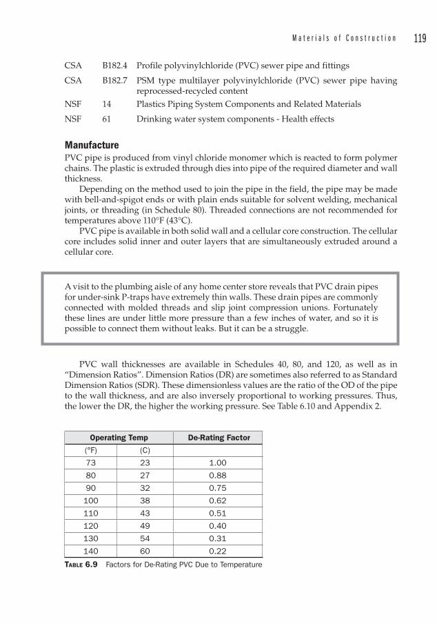
M a t e r i a l s o f C o n s t r u c t i o n 119
CSA B182.4 Profile polyvinylchloride (PVC ) sewer pipe and fittings
CSA B182.7 PSM type multilayer polyvinylchloride (PVC ) sewer pipe having reprocessed-recycled content
NSF 14 Plastics Piping System Components and Related Materials
NSF 61 Drinking water system components - Health effects
ManufacturePVC pipe is produced from vinyl chloride monomer which is reacted to form polymer chains. The plastic is extruded through dies into pipe of the required diameter and wall thickness .
Depending on the method used to join the pipe in the field, the pipe may be made with bell-and-spigot ends or with plain ends suitable for solvent welding, mechanical joints, or threading (in Schedule 80). Threaded connections are not recommended for temperatures above 110°F (43°C).
PVC pipe is available in both solid wall and a cellular core construction. The cellular core includes solid inner and outer layers that are simultaneously extruded around a cellular core.
A visit to the plumbing aisle of any home center store reveals that PVC drain pipes for under-sink P-traps have extremely thin walls. These drain pipes are commonly connected with molded threads and slip joint compression unions. Fortunately these lines are under little more pressure than a few inches of water, and so it is possible to connect them without leaks. But it can be a struggle.
PVC wall thicknesses are available in Schedules 40, 80, and 120, as well as in “Dimension Ratios”. Dimension Ratios (DR) are sometimes also referred to as Standard Dimension Ratios (SDR). These dimensionless values are the ratio of the OD of the pipe to the wall thickness , and are also inversely proportional to working pressures. Thus, the lower the DR, the higher the working pressure. See Table 6.10 and Appendix 2.
Operating Temp De-Rating Factor
(°F) (C)
73 23 1.00
80 27 0.88
90 32 0.75
100 38 0.62
110 43 0.51
120 49 0.40
130 54 0.31
140 60 0.22
TABLE 6.9 Factors for De-Rating PVC Due to Temperature
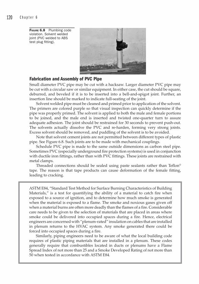
120 C h a p t e r 6
Fabrication and Assembly of PVC PipeSmall diameter PVC pipe may be cut with a hacksaw. Larger diameter PVC pipe may be cut with a circular saw or similar equipment. In either case, the cut should be square, deburred, and beveled if it is to be inserted into a bell-and-spigot joint. Further, an insertion line should be marked to indicate full-seating of the joint.
Solvent welded pipe must be cleaned and primed prior to application of the solvent. The primers are colored purple so that visual inspection can quickly determine if the pipe was properly primed. The solvent is applied to both the male and female portions to be joined, and the male end is inserted and twisted one-quarter turn to assure adequate adhesion. The joint should be restrained for 30 seconds to prevent push-out. The solvents actually dissolve the PVC and re-harden, forming very strong joints. Excess solvent should be removed, and puddling of the solvent is to be avoided.
Note that solvent cement joints are not permitted between different types of plastic pipe. See Figure 6.8. Such joints are to be made with mechanical couplings.
Schedule PVC pipe is made to the same outside dimensions as carbon steel pipe. Sometimes PVC (especially underground fire protection systems) is used in conjunction with ductile iron fittings, rather than with PVC fittings. These joints are restrained with metal clamps.
Threaded connections should be sealed using paste sealants rather than Teflon® tape. The reason is that tape products can cause deformation of the female fitting, leading to cracking.
FIGURE 6.8 Plumbing code violation. Solvent welded joint (PVC welded to ABS test plug fi tting).
ASTM E84, “Standard Test Method for Surface Burning Characteristics of Building Materials,” is a test for quantifying the ability of a material to catch fire when exposed to a source of ignition, and to determine how much smoke is generated when the material is exposed to a flame. The smoke and noxious gases given off when a material burns are often more deadly than the flames of a fire. Considerable care needs to be given to the selection of materials that are placed in areas where smoke could be delivered into occupied spaces during a fire. Hence, electrical engineers are concerned with “plenum-rated” insulation on cables that are installed in plenum returns to the HVAC system. Any smoke generated there could be forced into occupied spaces during a fire.
Similarly, piping engineers need to be aware of what the local building code requires of plastic piping materials that are installed in a plenum. These codes generally require that combustibles located in ducts or plenums have a Flame Spread Index of not more than 25 and a Smoke Developed Rating of not more than 50 when tested in accordance with ASTM E84.
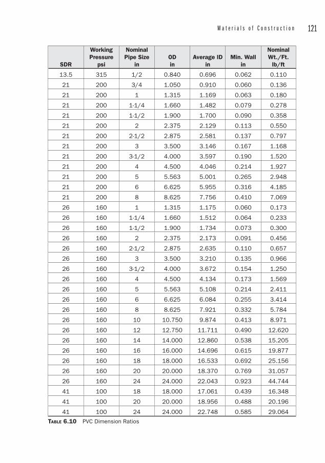
M a t e r i a l s o f C o n s t r u c t i o n 121
SDR
Working Pressure
psi
NominalPipe Size
inODin
Average IDin
Min. Wallin
NominalWt./Ft.
lb/ft
13.5 315 1/2 0.840 0.696 0.062 0.110
21 200 3/4 1.050 0.910 0.060 0.136
21 200 1 1.315 1.169 0.063 0.180
21 200 1-1/4 1.660 1.482 0.079 0.278
21 200 1-1/2 1.900 1.700 0.090 0.358
21 200 2 2.375 2.129 0.113 0.550
21 200 2-1/2 2.875 2.581 0.137 0.797
21 200 3 3.500 3.146 0.167 1.168
21 200 3-1/2 4.000 3.597 0.190 1.520
21 200 4 4.500 4.046 0.214 1.927
21 200 5 5.563 5.001 0.265 2.948
21 200 6 6.625 5.955 0.316 4.185
21 200 8 8.625 7.756 0.410 7.069
26 160 1 1.315 1.175 0.060 0.173
26 160 1-1/4 1.660 1.512 0.064 0.233
26 160 1-1/2 1.900 1.734 0.073 0.300
26 160 2 2.375 2.173 0.091 0.456
26 160 2-1/2 2.875 2.635 0.110 0.657
26 160 3 3.500 3.210 0.135 0.966
26 160 3-1/2 4.000 3.672 0.154 1.250
26 160 4 4.500 4.134 0.173 1.569
26 160 5 5.563 5.108 0.214 2.411
26 160 6 6.625 6.084 0.255 3.414
26 160 8 8.625 7.921 0.332 5.784
26 160 10 10.750 9.874 0.413 8.971
26 160 12 12.750 11.711 0.490 12.620
26 160 14 14.000 12.860 0.538 15.205
26 160 16 16.000 14.696 0.615 19.877
26 160 18 18.000 16.533 0.692 25.156
26 160 20 20.000 18.370 0.769 31.057
26 160 24 24.000 22.043 0.923 44.744
41 100 18 18.000 17.061 0.439 16.348
41 100 20 20.000 18.956 0.488 20.196
41 100 24 24.000 22.748 0.585 29.064
TABLE 6.10 PVC Dimension Ratios
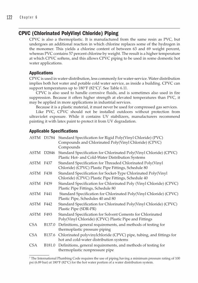
122 C h a p t e r 6
CPVC (Chlorinated PolyVinyl Chloride) PipingCPVC is also a thermoplastic. It is manufactured from the same resin as PVC , but undergoes an additional reaction in which chlorine replaces some of the hydrogen in the monomer. This yields a chlorine content of between 63 and 69 weight percent, whereas PVC contains 57 percent chlorine by weight. The result is a higher temperature at which CPVC softens, and this allows CPVC piping to be used in some domestic hot water applications.
ApplicationsCPVC is used in water-distribution, less commonly for water-service. Water distribution implies both hot water and potable cold water service, as inside a building. CPVC can support temperatures up to 180°F (82°C)7. See Table 6.11.
CPVC is also used to handle corrosive fluids, and is sometimes also used in fire suppression. Because it offers higher strength at elevated temperatures than PVC , it may be applied in more applications in industrial services.
Because it is a plastic material, it must never be used for compressed gas services.Like PVC , CPVC should not be installed outdoors without protection from
ultraviolet exposure. While it contains UV stabilizers, manufacturers recommend painting it with latex paint to protect it from UV degradation.
Applicable SpecificationsASTM D1784 Standard Specification for Rigid Poly(Vinyl Chloride) (PVC )
Compounds and Chlorinated Poly(Vinyl Chloride) (CPVC ) Compounds
ASTM D2846 Standard Specification for Chlorinated Poly(Vinyl Chloride) (CPVC ) Plastic Hot- and Cold-Water Distribution Systems
ASTM F437 Standard Specification for Threaded Chlorinated Poly(Vinyl Chloride) (CPVC ) Plastic Pipe Fittings, Schedule 80
ASTM F438 Standard Specification for Socket-Type Chlorinated Poly(Vinyl Chloride) (CPVC ) Plastic Pipe Fittings, Schedule 40
ASTM F439 Standard Specification for Chlorinated Poly (Vinyl Chloride) (CPVC ) Plastic Pipe Fittings, Schedule 80
ASTM F441 Standard Specification for Chlorinated Poly(Vinyl Chloride) (CPVC ) Plastic Pipe, Schedules 40 and 80
ASTM F442 Standard Specification for Chlorinated Poly(Vinyl Chloride) (CPVC ) Plastic Pipe (SDR-PR)
ASTM F493 Standard Specification for Solvent Cements for Chlorinated Poly(Vinyl Chloride) (CPVC ) Plastic Pipe and Fittings
CSA B137.0 Definitions, general requirements, and methods of testing for thermoplastic pressure piping
CSA B137.6 Chlorinated polyvinylchloride (CPVC ) pipe, tubing, and fittings for hot and cold-water distribution systems
CSA B181.0 Definitions, general requirements, and methods of testing for thermoplastic nonpressure pipe
7 The International Plumbing Code requires the use of piping having a minimum pressure rating of 100 psi (6.89 bar) at 180°F (82°C) for the hot water portion of a water distribution system.
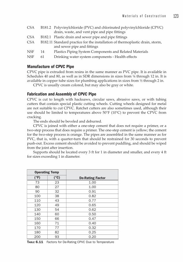
M a t e r i a l s o f C o n s t r u c t i o n 123
CSA B181.2 Polyvinylchloride (PVC ) and chlorinated polyvinylchloride (CPVC ) drain, waste, and vent pipe and pipe fittings
CSA B182.1 Plastic drain and sewer pipe and pipe fittingsCSA B182.11 Standard practice for the installation of thermoplastic drain, storm,
and sewer pipe and fittingsNSF 14 Plastics Piping System Components and Related MaterialsNSF 61 Drinking water system components - Health effects
Manufacture of CPVC PipeCPVC pipe is extruded from resins in the same manner as PVC pipe. It is available in Schedules 40 and 80, as well as in SDR dimensions in sizes from ¼ through 12 in. It is available in copper tube sizes for plumbing applications in sizes from ½ through 2 in.
CPVC is usually cream colored, but may also be gray or white.
Fabrication and Assembly of CPVC PipeCPVC is cut to length with hacksaws, circular saws, abrasive saws, or with tubing cutters that contain special plastic cutting wheels. Cutting wheels designed for metal are not suitable to cut CPVC. Ratchet cutters are also sometimes used, although their use should be limited to temperatures above 50°F (10°C) to prevent the CPVC from cracking.
The ends should be beveled and deburred.CPVC is joined with either a one-step cement that does not require a primer, or a
two-step process that does require a primer. The one-step cement is yellow; the cement for the two-step process is orange. The pipes are assembled in the same manner as for PVC , that is, with a quarter-turn that should be restrained for 30 seconds to prevent push-out. Excess cement should be avoided to prevent puddling, and should be wiped from the joint after insertion.
Supports should be located every 3 ft for 1 in diameter and smaller, and every 4 ft for sizes exceeding 1 in diameter.
Operating Temp
De-Rating Factor (°F) (°C)73 23 1.00 80 27 1.00 90 32 0.91
100 38 0.82 110 43 0.77 120 49 0.65 130 54 0.62 140 60 0.50 150 66 0.47160 71 0.40170 77 0.32180 82 0.25200 93 0.20
TABLE 6.11 Factors for De-Rating CPVC Due to Temperature
124 C h a p t e r 6
Polybutylene (PB) Piping Polybutylene piping was never used for industrial applications, although it has been used for both water distribution and water service piping. At least two class action lawsuits were filed in the United States alleging defects in the manufacture or installation of PB piping. The PB was favored by installers because it is a flexible system which is “forgiving” in terms of routing and avoiding interferences. The installer did not have to be dimensionally precise.
The problem with the material is thought to be that chlorine in public water supplies attacks the PB tubing and some of the fittings. This results in scaling, flaking, and brittleness, which culminates in failure of the system
PB piping was joined using acetal, brass, or copper fittings over which the tubing was placed and then secured with a metal band. PB tubing was colored blue, gray, or black.
Polyethylene (PE) and High-Density Polyethylene (HDPE ) PipingPolyethylene is a polymer thermoplastic that excels in certain underground applications. It belongs to a class of polymers known as polyolefins. It tolerates abuse and may be deformed without compromising its strength. It is made by the polymerization of ethylene with propylene, butene, or hexene. The result is a long polymer chain which can be modified to adjust the desired properties of the bulk material which will be extruded into pipe.
The three properties of density, molecular weight, and molecular weight distribution influence the physical properties of the material. In that sense, it should be noted that the composition of HDPE is analogous to steel. Various chemicals can be used to modify the properties of the final product in a manner similar to alloying materials in steels.
Early PE compositions had many side-branches coming off of the main polymer chain. These side branches prevented the polymer chains from packing together very
During a large steel mill project several years ago, the piping contractor suggested using HDPE for much of the underground water piping on the grounds that it would save time and money. We engineers exchanged skeptical glances, thinking they were just trying to pull a fast one. They explained how they felt it would be a poor application to use HDPE underground inside the melt shop, just in case a ladle of steel got loose, and we certainly agreed.
The contractor submitted some vendor information including a sample of the fusion weld. We immediately took turns trying to break the weld by hand or by propping it on a chair rung and kicking it. It wouldn’t budge. One of the designers suggested that this material might become brittle in the cold Ohio winters. (It would be exposed to the elements prior to burial). We left it in a freezer overnight, and went through the same exercise with no difference in the results. We decided that it would be satisfactory after reviewing some additional data with the vendor.
I became a supporter of HDPE for underground applications. It installs quickly, is less expensive than steel, and is nearly impervious. Sometimes the contractors are ahead of the curve.

M a t e r i a l s o f C o n s t r u c t i o n 125
tightly, and so were called “Low Density Polyethylene ” (LDPE). These are not often used for piping, since the higher density varieties exhibit more desirable qualities, such as improved tensile strength, improved low-temperature brittleness, higher softening point, and increased chemical resistance.
ApplicationsHDPE is often used to convey water or low-pressure natural gas. It does not corrode, and its flow characteristics are very good, since the surfaces are so smooth. The resistance to corrosion can make it a more economical choice for underground piping than coated and wrapped carbon steel, provided that the fluids are compatible with the material, and the pressures can be accommodated.
HDPE is only used above ground in installations that are regarded as temporary. It is snaked over grade in such applications. Due to its extreme flexibility (low Young’s Modulus) it would require extensive support for above ground installation.
Applicable SpecificationsAASHTO F2136 Standard Test Method for Notched, Constant Ligament-Stress
(NCLS) Test to Determine Slow-Crack Growth Resistance of HDPE Resins or HDPE Corrugated Pipe
AASHTO M294 Corrugated Polyethylene Pipe, 12 to 24 in DiameterAPI 15LE Specification for Polyethylene Line Pipe (American Petroleum
Institute)ASTM D2104 Polyethylene (PE) Plastic Pipe, Schedule 40ASTM D2239 Polyethylene (PE) Plastic Pipe (SIDR-PR) Based on Controlled
Inside DiameterASTM D2447 Polyethylene (PE) Plastic Pipe, Schedules 40 to 80, Based on Outside
DiameterASTM D2609 Plastic Insert Fittings for Polyethylene (PE) Plastic PipeASTM D2683 Socket Type Polyethylene Fittings for Outside Diameter Controlled
Polyethylene Pipe and Tubing ASTM D2683 Socket-Type Polyethylene Fittings for Outside Diameter-Controlled
Polyethylene Pipe and Tubing ASTM D2737 Polyethylene (PE) Plastic Tubing ASTM D3035 Polyethylene (PE) Plastic Pipe (SDR-PR) Based on Controlled
Outside DiameterASTM D3261 Butt Heat Fusion Polyethylene (PE) Plastic Fittings for Polyethylene
(PE) Plastic Pipe and Tubing ASTM D3350 Polyethylene Plastics Pipe and Fittings MaterialsASTM F1025 Selection and Use of Full-Encirclement-Type Band Clamps for
Reinforcement or Repair of Punctures or Holes in Polyethylene Gas Pressure Pipe
ASTM F1055 Electrofusion Type Polyethylene Fittings for Outside Diameter Controlled Polyethylene Pipe and Tubing
ASTM F1056 Socket Fusion Tools for Use in Socket Fusion Joining Polyethylene Pipe or Tubing and Fittings
126 C h a p t e r 6
ASTM F1248 Test Method for Determination of Environmental Stress Crack Resistance (ESCR) of Polyethylene Pipe
ASTM F1282 Standard Specification Polyethylene /Aluminum/ Polyethylene (PE-AL -PE) Composite Pressure Pipe
ASTM F1473 Notch Tensile Test to Measure the Resistance to Slow Crack Growth of Polyethylene Pipes and Resins
ASTM F1533 Deformed Polyethylene (PE) LinerASTM F1563 Tools to Squeeze Off Polyethylene (PE) Gas Pipe or Tubing ASTM F1606 Standard Practice for Rehabilitation of Existing Sewers and
Conduits with Deformed Polyethylene (PE) LinerASTM F1734 Practice for Qualification of a Combination of Squeeze Tool, Pipe,
and Squeeze-Off Procedure to Avoid Long-Term Damage in Polyethylene (PE) Gas Pipe
ASTM F1759 Standard Practice for Design of High-Density Polyethylene (HDPE ) Manholes for Subsurface Applications
ASTM F1804 Determine Allowable Tensile Load For Polyethylene (PE) Gas Pipe During Pull-in Installation
ASTM F1901 Polyethylene (PE) Pipe and Fittings for Roof Drain SystemsASTM F1924 Plastic Mechanical Fittings for Use on Outside Diameter
Controlled Polyethylene Gas Distribution Pipe and Tubing ASTM F1962 Standard Guide for Use of Maxi-Horizontal Directional Drilling
for Placement of Polyethylene Pipe or Conduit Under Obstacles, Including River Crossing
ASTM F1973 Factory Assembled Anodeless Risers and Transition Fittings in Polyethylene (PE) Fuel Gas Distribution Systems
ASTM F2164 Standard Practice for Field Leak Testing of Polyethylene (PE) Pressure Piping Systems Using Hydrostatic Pressure
ASTM F2206 Standard Specification for Fabricated Fittings of Butt-Fused Polyethylene (PE) Plastic Pipe, Fittings, Sheet Stock, Plate Stock, or Block Stock
ASTM F2231 Standard Test Method for Charpy Impact Test on Thin Specimens of Polyethylene Used in Pressurized Pipes
ASTM F2263 Standard Test Method for Evaluating the Oxidative Resistance of Polyethylene (PE) Pipe to Chlorinated Water
ASTM F405 Corrugated Polyethylene (PE) Tubing and FittingsASTM F667 Large Diameter Corrugated Polyethylene (PE) Tubing and FittingsASTM F714 Polyethylene (PE) Plastic Pipe (SIDR-PR) Based on Controlled
Outside DiameterASTM F771 Polyethylene (PE) Thermoplastic High-Pressure Irrigation
Pipeline SystemsASTM F810 Smooth Wall Polyethylene (PE Pipe for Use in Drainage and
Waste Disposal Absorption FieldsASTM F858 Insertion of Flexible Polyethylene Pipe into Existing SewersASTM F894 Polyethylene (PE) Large Diameter Profile Wall Sewer and Drain
Pipe
M a t e r i a l s o f C o n s t r u c t i o n 127
ASTM F905 Qualification of Polyethylene Saddle Fusion JointsASTM F982 Polyethylene (PE) Corrugated Pipe with a Smooth Interior and
FittingsAWWA C901 Polyethylene (PE) Pressure Pipe and Tubing , ½ in (13 mm)
through 3 in (76 mm), for Water ServiceAWWA C906 Polyethylene (PE) Pressure Pipe and Fittings, 4 in (100 mm)
through 63 in (1600 mm), for Water Distribution AWWA M55 PE Pipe - Design and InstallationCSA B137.1 Polyethylene (PE) Pipe, Tubing, and Fittings for Cold-Water
Pressure ServicesCSA B137.4 Polyethylene Piping Systems for Gas Services (Canadian
Standards Association)CSA B137.4.1 Electrofusion-type Polyethylene (PE) Fittings for Gas ServicesCSA B137.9 Polyethylene /Aluminum/Polyethylene (PE-AL-PE) Composite
Pressure-Pipe SystemsCSA B182.6 Profile polyethylene (PE) Sewer Pipe and Fittings for Leak-Proof
Sewer ApplicationsCSA B182.8 Profile Polyethylene (PE) Storm Sewer and Drainage Pipe and
FittingsFM 1613 Polyethylene (PE) Pipe and Fittings for Underground Fire
Protection ServiceISO 4427 Polyethylene (PE) Pipes for Water SupplyISO 4437 Buried polyethylene (PE) Pipes for the Supply of Gaseous Fuels -
Metric Series - SpecificationsNSF 14 Plastics Piping System Components and Related MaterialsNSF 61 Drinking Water System Components - Health EffectsPPI MS-2 Model Specification for Polyethylene Plastic Pipe, Tubing and
Fittings for Natural Gas DistributionPPI MS-3 Model Specification for Polyethylene Plastic Pipe, Tubing and
Fittings for Water Mains and DistributionPPI TN-13 General Guidelines for Butt, Saddle, and Socket Fusion of Unlike
Polyethylene Pipes and FittingsPPI TN-15 Resistance of Solid Wall Polyethylene Pipe to a Sanitary Sewage
EnvironmentPPI TN-16 Rate Process Method for Projecting Performance of Polyethylene
Piping ComponentsPPI TN-4 Odorants in Plastic Fuel Gas Distribution SystemsPPI TN-6 Polyethylene (PE) Coil DimensionsPPI TR-22 Polyethylene Plastic Piping Distribution Systems for Components
of Liquid Petroleum GasPPI TR-33 Generic Butt Fusion Joining Procedure for Polyethylene Gas PipePPI TR-34 Disinfection of Newly Constructed Polyethylene Water MainsPPI TR-35 Chemical and Abrasion Resistance of Corrugated Polyethylene
Pipe
128 C h a p t e r 6
PPI TR-36 Hydraulic Considerations for Corrugated Polyethylene PipePPI TR-37 CPPA Standard Specification (100-99) for Corrugated Polyethylene
(PE) Pipe for Storm Sewer ApplicationsPPI TR-38 Structural Design Method for Corrugated Polyethylene PipePPI TR-39 Structural Integrity of Non-Pressure Corrugated Polyethylene
PipePPI TR-40 Evaluation of Fire Risk Related to Corrugated Polyethylene Pipe
Manufacture of PE pipePE resin is extruded into pipe diameters ranging from ½ to 63 in diameter. It is often pigmented solid black, but may be coextruded with other colors as stripes to denote different services. There are three different dimensioning systems to describe the wall thickness of PE piping:
1. Dimension Ratio – The wall thickness is determined using the diameter divided by the wall thickness. This provides a ratio that is based on an allowable working pressure for all of the diameters in a given Dimension Ratio (DR).
2. Iron Pipe Size Inside Diameter (SIDR) – The ID of the PE pipe matches the ID of Schedule 40 steel pipe, and the wall thicknesses vary in accordance with the pressure rating of the pipe. This designation is available in smaller sizes (approximately 2 in and less).
3. Copper Tube Size Outside Diameter (CTS) – The pipe ODs are the same as for copper tubing, i.e., the OD is 1/8 in larger than the nominal size. These are also available only in smaller sizes.
The dimension ratio system is the one used most often for industrial piping, but the pipe manufacturers specify the dimension ratio in two ways:
IDR � ID/t for pipes manufactured according to a controlled ID
and
DR � OD/t for pipes manufactured according to a controlled OD
These two terms are important in determining the allowable working pressure of the pipe. The plastics industry has developed equations (called ISO equations) for calculating the allowable stresses that look similar to the familiar Barlow’s formula, with modifications for the environment, the operating temperature, and the dimension ratio.
Thus, for pipe manufactured to a controlled OD,
P � [2 (HDB) � FE � FT] / (DR � 1)
where
HDB � Hydrostatic Design Basis (see Table 6.12)
FE � Environmental Design Factor based on the service fluid (see Table 6.13)
FT � Service Temperature Design Factor (see Table 6.14)

M a t e r i a l s o f C o n s t r u c t i o n 129
and for pipe manufactured to a controlled ID,
P � [2 (HDB) � FE � FT] / (IDR � 1)
Certain dimension ratios that meet ASTM-specified number series are known as “Standard Dimension Ratios” (SDR) or SIDR, and this terminology is also found in vendor data. Standard Dimension Ratios are: 41, 32.5, 26, 21, 17, 13.5, 11, 9, and 7.3. There is approximately a 25 percent difference in minimum wall thickness from one SDR to the next.
Care must be taken to use the HDB values and not the HDS values. The HDS is the Hydrostatic Design Stress, and
HDS � HDB � FE
Molded PE fittings require a larger body to provide additional wall thickness for a given pressure rating. Similarly, fabricated fittings made from straight pipe segments are usually derated at least one SDR.
Property PE 4710 PE 3408 PE 2406
Density Cell Class per ASTM D3350
4 3 2
Slow Crack Growth (SCG) Cell Class per ASTM D3350
7 4 4
Hydrostatic Design Stress (HDS) at 73°F (23°C)
1000 psi (6.89 MPa)
800 psi (5.52 Mpa)
600 psi (4.14 MPa)
Hydrostatic Design Basis at 73°F (23°C)
2000 psi (13.79 MPa)
1600 psi (11.04 MPa)
1250 psi (8.62 MPa)
Maximum recommended temperature for Pressure Service
Check with manufacturer
140°F (60°C) 140°F (60°C)
Maximum Recommended Temperature forNon-Pressure Service
Check with manufacturer
180°F (82°C) 180°F (82°C)
TABLE 6.12 Properties of PE Plastics for Piping
Fluid FE
Fluids such as potable and process water, benign chemicals, dry natural gas (non-federally regulated), brine, CO2, H2S, wastewater, sewage, glycol/anti-freeze solutions
0.50
Dry natural gas (Federally regulated under CFR Title 49, Part 192), 0.32Fluids such as solvating/permeating chemicals in pipe or soil (typically hydrocarbons) in 2% or greater concentrations, natural or other fuel-gas liquid condensates, crude oil, fuel oil, gasoline, diesel, kerosene, hydrocarbon fuels
0.25
TABLE 6.13 Environmental Design Factors, FE, for HDPE Pipe
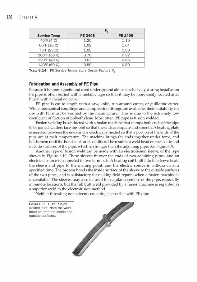
130 C h a p t e r 6
Fabrication and Assembly of PE PipeBecause it is nonmagnetic and used underground almost exclusively, during installation PE pipe is often buried with a metallic tape so that it may be more easily located after burial with a metal detector.
PE pipe is cut to length with a saw, knife, run-around cutter, or guillotine cutter. While mechanical couplings and compression fittings are available, their suitability for use with PE must be verified by the manufacturer. This is due to the extremely low coefficient of friction of polyethylene. Most often, PE pipe is fusion welded.
Fusion welding is conducted with a fusion machine that clamps both ends of the pipe to be joined. Cutters face the joint so that the ends are square and smooth. A heating plate is inserted between the ends and is electrically heated so that a portion of the ends of the pipe are at melt temperature. The machine brings the ends together under force, and holds them until the bond cools and solidifies. The result is a weld bead on the inside and outside surfaces of the pipe, which is stronger than the adjoining pipe. See Figure 6.9.
Another type of fusion weld can be made with an electrofusion sleeve , of the type shown in Figure 6.10. These sleeves fit over the ends of two adjoining pipes, and an electrical source is connected to two terminals. A heating coil built into the sleeve heats the sleeve and pipe to the melting point, and the electric source is withdrawn at a specified time. The process bonds the inside surface of the sleeve to the outside surfaces of the two pipes, and is satisfactory for making field repairs when a fusion machine is unavailable. The sleeves may also be used for regular assembly of the pipe, especially in remote locations, but the full butt weld provided by a fusion machine is regarded as a superior weld to the electrofusion method.
Neither threading nor solvent cementing is possible with PE pipe.
Service TempFT
PE 3408 PE 240640°F (4 C) 1.20 1.10
60°F (16 C) 1.08 1.0473°F (23 C) 1.00 1.00100°F (38 C) 0.78 0.92120°F (49 C) 0.63 0.86140°F (60 C) 0.50 0.80
TABLE 6.14 PE Service Temperature Design Factors, FT
FIGURE 6.9 HDPE fusion welded joint. Note the weld bead on both the inside and outside surfaces.
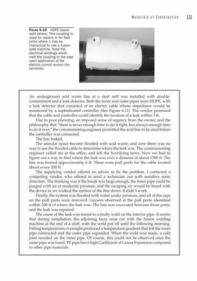
M a t e r i a l s o f C o n s t r u c t i o n 131
An underground acid waste line at a steel mill was installed with double-containment and a leak detector. Both the inner and outer pipes were HDPE , with a leak detector that consisted of an electric cable whose impedance would be monitored by a sophisticated controller (See Figure 6.11). The vendor promised that the cable and controller could identify the location of a leak within 3 ft.
Due to poor planning, an imposed sense of urgency from the owner, and the philosophy that “there is never enough time to do it right, but always enough time to do it over,” the commissioning engineer permitted the acid line to be used before the controller was connected.
The line leaked.The annular space became flooded with acid waste, and now there was no
way to use the flooded cable to determine where the leak was. The commissioning engineer called me at the office, and left the horrifying news. Now we had to figure out a way to find where the leak was over a distance of about 1500 ft. The line was buried approximately 6 ft. There were pull ports for the cable located about every 200 ft.
The supplying vendor offered no advice to fix the problem. I contacted a competing vendor, who offered to send a technician out with sensitive sonic detectors. The thinking was if the break was large enough, the inner pipe could be purged with air at moderate pressure, and the escaping air would be heard with the device as we walked the surface of the line down. It didn’t work.
Finally, the system was flooded with water under pressure, and all of the caps on the pull ports were removed. Geysers observed at the pull ports identified within 200 ft of where the leak was. The line was excavated between those ports, and the leak was repaired.
The cause of the leak was traced to a faulty weld on the interior pipe. It seems that during installation, the adjoining faces were cut with the fusion welding machine at the end of a shift, with the weld put off until the following morning. Falling temperatures overnight produced a temperature gradient that left the inner pipe contracted and the outer pipe expanded. When the weld was made, a cold joint resulted on the inner pipe. Of course, this could not be observed once the outer pipe was fused. PE pipe has a high Coefficient of Linear Expansion compared to other pipe materials.
FIGURE 6.10 HDPE fusion weld sleeve. This coupling is used for repairs or for fi eld joints where it may be impractical to use a fusion weld machine. Note the electrical windings which melt the coupling to the pipe upon application of the electric current across the terminals.
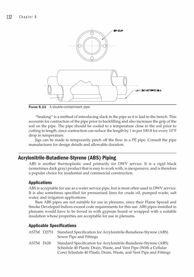
132 C h a p t e r 6
“Snaking” is a method of introducing slack in the pipe as it is laid in the trench. This accounts for contraction of the pipe prior to backfilling and also increases the grip of the soil on the pipe. The pipe should be cooled to a temperature close to the soil prior to cutting to length, since contraction can reduce the length by 1 in per 100 ft for every 10°F drop in temperature.
Jigs can be made to temporarily pinch off the flow in a PE pipe. Consult the pipe manufacturer for design details and allowable duration.
Acrylonitrile-Butadiene-Styrene (ABS ) PipingABS is another thermoplastic used primarily for DWV service. It is a rigid black (sometimes dark gray) product that is easy to work with, is inexpensive, and is therefore a popular choice for residential and commercial construction.
ApplicationsABS is acceptable for use as a water service pipe, but is most often used in DWV service. It is also sometimes specified for pressurized lines for crude oil, pumped waste, salt water, and irrigation applications.
Bare ABS pipes are not suitable for use in plenums, since their Flame Spread and Smoke Developed Indices exceed code requirements for this use. ABS pipes installed in plenums would have to be boxed in with gypsum board or wrapped with a suitable insulation whose properties are acceptable for use in plenums.
Applicable SpecificationsASTM D2751 Standard Specification for Acrylonitrile-Butadiene-Styrene (ABS )
Sewer Pipe and Fittings
ASTM F628 Standard Specification for Acrylonitrile-Butadiene-Styrene (ABS ) Schedule 40 Plastic Drain, Waste, and Vent Pipe (With a Cellular Core) Schedule 40 Plastic Drain, Waste, and Vent Pipe and Fittings
FIGURE 6.11 A double-containment pipe.
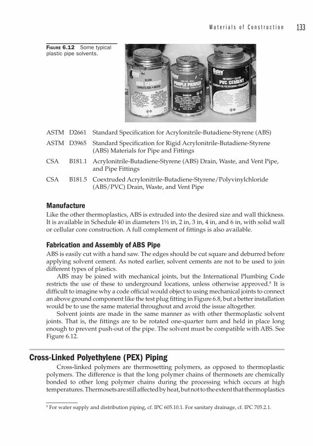
M a t e r i a l s o f C o n s t r u c t i o n 133
ASTM D2661 Standard Specification for Acrylonitrile-Butadiene-Styrene (ABS )
ASTM D3965 Standard Specification for Rigid Acrylonitrile-Butadiene-Styrene (ABS ) Materials for Pipe and Fittings
CSA B181.1 Acrylonitrile-Butadiene-Styrene (ABS ) Drain, Waste, and Vent Pipe, and Pipe Fittings
CSA B181.5 Coextruded Acrylonitrile-Butadiene-Styrene/Polyvinylchloride (ABS /PVC ) Drain, Waste, and Vent Pipe
ManufactureLike the other thermoplastics, ABS is extruded into the desired size and wall thickness . It is available in Schedule 40 in diameters 1½ in, 2 in, 3 in, 4 in, and 6 in, with solid wall or cellular core construction. A full complement of fittings is also available.
Fabrication and Assembly of ABS PipeABS is easily cut with a hand saw. The edges should be cut square and deburred before applying solvent cement. As noted earlier, solvent cements are not to be used to join different types of plastics.
ABS may be joined with mechanical joints, but the International Plumbing Code restricts the use of these to underground locations, unless otherwise approved.8 It is difficult to imagine why a code official would object to using mechanical joints to connect an above ground component like the test plug fitting in Figure 6.8, but a better installation would be to use the same material throughout and avoid the issue altogether.
Solvent joints are made in the same manner as with other thermoplastic solvent joints. That is, the fittings are to be rotated one-quarter turn and held in place long enough to prevent push-out of the pipe. The solvent must be compatible with ABS . See Figure 6.12.
Cross-Linked Polyethylene (PEX ) PipingCross-linked polymers are thermosetting polymers, as opposed to thermoplastic
polymers. The difference is that the long polymer chains of thermosets are chemically bonded to other long polymer chains during the processing which occurs at high temperatures. Thermosets are still affected by heat, but not to the extent that thermoplastics
8 For water supply and distribution piping, cf. IPC 605.10.1. For sanitary drainage, cf. IPC 705.2.1.
FIGURE 6.12 Some typical plastic pipe solvents.
134 C h a p t e r 6
are. Thermoset plastics are not recyclable, in the sense that they cannot be ground up and remelted to form the same compound.
ApplicationsPEX is used in hot and cold water piping for water distribution systems and in radiant heating applications including snow melt systems. It is not intended for outdoor use.
PEX tubing for heating is available with an oxygen barrier to prevent oxygen from corroding cast iron system components. The oxygen barriers are available as a PEX-Aluminum-PEX composite system in which the aluminum prevents oxygen from permeating the tube. The other oxygen barrier is identifiable as a red coating on the PEX tube exterior.
Applicable SpecificationsASTM F876 Cross-linked Polyethylene (PEX ) Tubing
ASTM F877 Cross-linked Polyethylene (PEX ) Plastic Hot- and Cold-Water Distribution Systems
ASTM F1281 Standard Specification for Cross-linked Polyethylene /Aluminum/ Cross-linked Polyethylene (PEX -AL-PEX) Pressure Pipe
ASTM F1807 Metal Insert Fittings Utilizing a Copper Crimp Ring for SDR 9 Cross-linked Polyethylene (PEX ) Tubing
ASTM F1865 Mechanical Cold Expansion Insert Fitting With Compression Sleeve for Cross-linked Polyethylene (PEX ) Tubing
ASTM F1960 Mechanical Cold Expansion Insert Fittings with PEX Reinforcing Rings for Use with Cross-linked (PEX) Tubing
ASTM F1961 Metal Mechanical Cold Flare Compression Fittings with Disc Spring for Cross-linked Polyethylene (PEX ) Tubing
ASTM F1974 Standard Specification for Metal Insert Fittings for Polyethylene /Aluminum/Polyethylene and Cross-linked Polyethylene/Aluminum/Cross-linked Polyethylene Composite Pressure Pipe
ASTM F2023 Standard Test Method for Evaluating the Oxidative Resistance of Cross-linked Polyethylene (PEX ) Tubing and Systems to Hot Chlorinated Water
ASTM F2080 Cold Expansion Fittings with Metal Compression Sleeves for Cross-linked Polyethylene (PEX ) Pipe
ASTM F2098 Stainless Steel Clamps for Securing SDR 9 Cross-linked Polyethylene (PEX ) Tubing to Metal Insert Fittings
ASTM F2159 Standard Specification for Plastic Insert Fittings Utilizing a Copper Crimp Ring for SDR9 Cross-linked Polyethylene (PEX ) Tubing
ASTM F2262 Standard Specification for Cross-linked Polyethylene /Aluminum/Cross-linked Polyethylene Tubing OD Controlled SDR9
AWWA C903 Polyethylene -Aluminum-Polyethylene Composite Pressure Pipes

M a t e r i a l s o f C o n s t r u c t i o n 135
AWWA C904 Cross-Linked Polyethylene (PEX ) Pressure Pipe, 1/2 in (12 mm) through 3 in (76 mm), for Water Service
CSA B137.10 Crosslinked Polyethylene/Aluminum/Cross-Linked Polyethylene (PEX -AL-PEX) Composite Pressure-Pipe Systems
CSA B137.5 Cross-linked Polyethylene (PEX ) Tubing Systems for Pressure Applications
Manufacture of PEX Tubing There are three methods used to manufacture PEX tubing:
1. The “Engel” method (PEX -A) uses a special extruder with a plunger action in which peroxide is added to the resin. The cross-linking occurs through a combination of pressure and high temperature, and the tubing is extruded through a die.
2. The “Silane” method (PEX -B) attaches a silane molecule to the base polyethylene molecule with the aid of a catalyst. After extrusion through a die, the tubing is heated with steam or hot water to cross-link (thermoset) the polymer.
3. The electron beam method (PEX -C) begins with normal HDPE tubing which is exposed to high-energy electron beam radiation. This removes hydrogen atoms from the chain and causes them to bond at the location of the missing hydrogen atoms.
The designations PEX -A, PEX-B, and PEX-C are more common in Europe. The means of manufacture however does not significantly affect performance, and the three varieties may be treated as identical. More important is whether the tubing is certified to meet the appropriate specification.
PEX is available in Copper Tube Sizes 1⁄4 through 2 in. It is usually available in coils but can also be purchased in 20 ft straight lengths. The wall thicknesses vary to achieve an SDR 9 rating. PEX is rated for long-term service at temperatures up to 180°F (82°C) and a working pressure of 100 psi.
Fabrication and Assembly of PEX Tubing Because it is a flexible material, PEX finds favor among some plumbers because the need for dimensional accuracy during routing is eliminated. Still, there are good and bad practices in routing and workmanship, and the tube has limits on how much bend it can accept without compromising the strength of the product. Similarly, adequate support of any piping system is always important, whether or not the system is flexible. The maximum recommended support of horizontal tube runs is 32 in (800 mm) for tubing up to 1 in diameter. This would be a practical spacing across the range of sizes however.
The tubing may be cut with plastic tubing cutters. A variety of methods are used to join the tubes. Some require the tube to be expanded over a fitting, and some require a ring to be crimped over the end of the tube. Regardless, it is important to provide square cuts without burrs on the ends of the tube.
Fiberglass Reinforced Plastic (FRP ) PipingFiberglass Reinforced Plastic (FRP ) is a composite material with wide use due to its chemical resistance and strength. The resins are thermosetting epoxy or polyester and

136 C h a p t e r 6
the glass fibers are embedded within these resins to impart mechanical strength. The orientation of the fibers and the resin blend can be manipulated to obtain the desired quality for the specific application.
ApplicationsFRP piping is used to convey chemicals in liquid or vapor phases. It often finds use in fume scrubbers, ductwork, stacks, and fuel, acids, caustics, and solvents piping. It therefore is frequently used in oil field applications. It is also used to convey water in industrial applications. FRP may be used in both above and below ground installations.
Because FRP does not conduct electricity, caution must be exercised in handling flammable liquids so that static electricity discharge does not create an ignition source9. Test data appears to indicate that the velocity of the fluid inside the pipe is responsible for static electricity build-up, and a practical maximum limit for fuels inside nonconductive piping such as FRP is thought to be 12 ft per second (3.6 m/sec). Additional precautions such as grounding metal valves and fittings are also recommended, as well as wrapping the FRP with a copper wire helix and grounding it at regular intervals of approximately 500 ft (150 m).
FRP has a maximum temperature rating of 250°F (121°C).
9 Sullivan D. Curran, PE. (n.d.). Static Electricity in Fuel Handling Facilities. Retrieved November 22, 2008, from Fiberglass Tank and Pipe Institute: http://www.fiberglasstankandpipe.com/static.htm.
Static electricity can also become a problem in some metallic piping systems. At one plant where I worked, we had a pellet handling system that pneumatically conveyed polypropylene pellets from railcars to extruder hoppers. The system was made out of plain end aluminum tubing, with stainless steel mechanical clamps that sealed the tubes with a white elastomer gasket around the joint, securing it within the SS sleeve with a 3-bolt clamp.
The construction engineer instructed the contractor to remove the brass inserts on the clamps, reckoning that these were supplied to hold the clamps together during shipment. These brass strips were actually supplied to provide a continuous electrical path across the joints so that the entire system could be grounded. High velocity polypropylene can create some serious static charges.
Upon realizing that the system was now ungrounded, the plant engineer decided to provide a ground by welding aluminum lugs on both sides of each joint and connecting an external wire. This had the advantage of providing a visible ground, but it had the disadvantage of preventing the removal of the clamps, which could not be slid off of the joint due to the lugs.
Applicable SpecificationsANSI D5421 Standard Specification for Contact Molded “Fiberglass ” (Glass-
Fiber-Reinforced Thermosetting Resin) Flanges
API 14LR Specification for Low Pressure Fiberglass Line Pipe
API 15HR Specification for High Pressure Fiberglass Line Pipe
API RP 15TL4 Recommended Practice for Care and Use of Fiberglass Tubulars
ASTM D2996 Filament Wound Fiberglass (Glass-Fiber-Reinforced Thermosetting Resin) Pipe
M a t e r i a l s o f C o n s t r u c t i o n 137
ASTM D2997 Centrifugally Cast Fiberglass (Glass-Fiber-Reinforced Thermosetting Resin) Pipe
ASTM D3262 Fiberglass (Glass-Fiber-Reinforced Thermosetting Resin) Sewer Pipe
ASTM D3754 Fiberglass (Glass-Fiber-Reinforced Thermosetting Resin) Sewer and Industrial Pressure Pipe
AWWA C950 Fiberglass Pressure Pipe
UL 971 Nonmetallic Underground Piping for Flammable Liquids
Manufacture of FRP FRP pipe is made by winding glass filaments around a mandrel. These glass filaments are responsible for imparting the mechanical strength of the pipe, and ratings up to 450 psi can be achieved. The resins are responsible for the resistance to corrosion, and often an interior or exterior lining may be applied to offer increased corrosion resistance. These linings do not contain much, if any, reinforcement, and so they must not be included in strength calculations.
In a sense, FRP piping may be thought of as tubing since it is built up over a mandrel (the ID is set by the size of the mandrel) and the wall thickness may be varied to achieve the desired physical properties. In other words, FRP is specified by ID and wall thickness, just like tubing.
Special “oil field tubular” can be manufactured with pressure ratings up to 3000 psi, but these are for “down-hole” applications.
FRP pipe diameters range from 1 to 108 in.
Fabrication and Assembly of FRP PipeFRP piping is commonly cut to length with abrasive saws. The joints may be bell and spigot , threaded, butted, or mechanical joint. Except for mechanical joints, the others are generally secured with adhesive and wrapped with a glass cloth for additional strength.
Concrete Pipe Concrete pipe may be either reinforced (RCP) or non-reinforced, and is used in pressure and gravity applications.
ApplicationsConcrete pipe is often used for storm and sanitary sewers. Pressurized services are usually nonpotable cooling or process water.
Applicable SpecificationsASTM C14 Standard Specification for Concrete Sewer, Storm Drain, and
Culvert Pipe ASTM C76 Reinforced Concrete Culvert, Storm Drain, and Sewer Pipe
(AASHTO M170)ASTM C361 Reinforced Concrete Low-Head Pressure Pipe
ASTM C443 Joints for Circular Concrete Sewer and Culvert Pipe, Using Rubber Gaskets (AASHTO M198)
138 C h a p t e r 6
ASTM C478 Precast Reinforced Concrete Manhole Sections (AASHTO M199)
ASTM C497 Standard Methods of Testing Concrete Pipe , Sections or Tile (AASHTO T33)
ASTM C507 Reinforced Concrete Elliptical Culvert, Storm Drain, and Sewer Pipe (AASHTO M207)
ASTM C655 Reinforced Concrete D-Load Culvert, Storm Drain, and Sewer Pipe (AASHTO M242)
ASTM C822 Standard Definitions of Terms Relating to Concrete Pipe and Related Products
ASTM C924 Testing Concrete Pipe Sewer Lines by Low-Pressure Air Test MethodASTM C969 Infiltration and Exfiltration Acceptance Testing of Installed Precast
Concrete Pipe Sewer LinesASTM C1103 Joint Acceptance Testing of Installed Concrete Pipe Sewer Lines
ASTM C1131 Least Cost (Life Cycle) Analysis of Concrete Culvert, Storm Sewer, and Sanitary Sewer Systems
ASTM C1214 Concrete Pipe Sewer Lines by Negative Air Pressure (Vacuum) Test Method
ASTM C1244 Standard Test Method for Concrete Sewer Manholes by Negative Air Pressure (Vacuum) Test (Metric)
ASTM C1433 Precast Reinforced Concrete Box Sections for Culverts, Storm Drains and Sewers (AASHTO M259)
AWWA C300 Reinforced Concrete Pressure Pipe, Steel-Cylinder Type
AWWA C301 Prestressed Concrete Pressure Pipe, Steel-Cylinder Type
AWWA C302 Reinforced Concrete Pressure Pipe, Noncylinder Type
AWWA C303 Concrete Pressure Pipe, Bar-Wrapped, Steel-Cylinder Type
AWWA C304 Design of Prestressed Concrete Cylinder Pipe
Manufacture of Concrete Pipe Nonreinforced concrete pipe is available in sizes from 4 to 36 in, in two strength classes: standard and extra strength. Reinforced concrete pipe is available in sizes from 12 to 144 in. RCP is available is five strength classes, according to the load requirements set forth in ASTM C 76 (AASHTO M170). See Table 6.15.
The 0.01 in crack loads were developed in an effort to quantify “visible” cracks. As used in ASTM C76, the 0.01 in crack is a test criterion for concrete pipe tested in a three-edge bearing test and is not intended as a criterion of failure.
Class 0.01 in Crack Ultimate
I 800 lb 1,200 lb
II 1,000 lb 1,500 lb
III 1,350 lb 2,000 lb
IV 2,000 lb 3,000 lb
V 3,000 lb 3,750 lb
TABLE 6.15 RCP Strength Classes
M a t e r i a l s o f C o n s t r u c t i o n 139
Fabrication and Assembly of Concrete PipeConcrete pipe is manufactured with gasketed bell joint ends, so assembly involves driving the straight spigot end into the bell. For small diameters, the spigot may be driven into the bell with a pry bar. For larger diameters a come-along may be used, although this task is often done using the bucket of a backhoe. The backhoe straddles the trench, and the bucket presses against the bell, driving the opposite end (the spigot) into the bell of the adjoining pipe. Concrete pipe manufacturers warn against using this method, unless precautions are taken to prevent localized stresses from being placed on the bell. The direction of lay of bell-and-spigot concrete pipe should be with the bells upstream. Figure 6.13 provides additional information regarding the handling and installation of concrete pipe.
It is frequently necessary to join concrete pipe to a manhole. In the past, these were built with masonry. It is far more common for these to be prefabricated concrete structures now, with the penetrations already cast in. The annulus between the OD of the pipe and the ID of the penetration is often sealed with an elastomeric band that may be tightened to form a watertight seal. See Figure 6.14. Care must be exercised to ensure that the plane of the seal lies entirely within the plane cut by the penetrating pipe in the radius of curvature of the manhole wall. See Figure 6.15.
Asbestos Cement Pipe Asbestos has been used in various forms since ancient times. The developed ancient cultures marveled at its properties, and wove tablecloths out of it that could be cleaned by immersing in fire. The ancient Romans noticed that slaves who worked with the mineral fibers sometimes developed lung disease.
Use of asbestos grew throughout the industrial revolution and it was used in many products for its resistance to heat and its ability to be woven into cloth. It has been used as a component of cement piping since 1913 in Italy, and production of asbestos cement pipe in the U.S. began in 1929.
Manufacture of asbestos cement pipe continues today in spite of the health hazards associated with asbestos. The use of asbestos in new construction is banned by the European Union, Australia, Japan, and New Zealand.
Some controversy exists over the lack of a direct link to health hazards through the use of asbestos in water piping. Several studies have been conducted, but the results to date do not appear to prove a link between various cancers and the use of asbestos cement pipe in water supplies. Usually, the route of exposure to asbestos that causes the greatest concern is inhalation. While this is a potential route of exposure to workers who demolish or install asbestos cement pipes, it is not a normal exposure route to consumers who utilize tap water, unless the fibers are freed from the cement-asbestos matrix. This can occur if the lines are exposed to acidic water that tends to dissolve the cement.
So there are two concerns for consumers: ingestion of asbestos fibers, and inhalation of asbestos fibers due to the evaporation of water, as in a clothes dryer, a humidifier, or a vaporizer.
Thousands of miles of asbestos cement water piping have been installed throughout North America alone, and tests in some cities have revealed millions of fibers present in a quart of tap water.
Though the jury is still out on the health risks associated with the ingestion of fibers from asbestos cement piping, the prudent engineer might give serious consideration to erring on the safe side, especially since many years sometimes pass between exposure
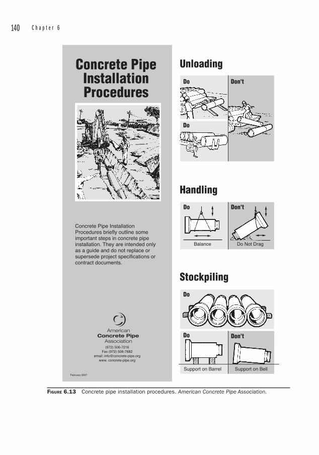
140 C h a p t e r 6
Do
Do
Don't
Do
Balance Do Not Drag
Support on Barrel Support on Bell
Don't
Do
Do Don't
Concrete PipeInstallationProcedures
Concrete Pipe Installation Procedures briefly outline some important steps in concrete pipe installation. They are intended only as a guide and do not replace or supersede project specifications or contract documents.
(972) 506-7216Fax (972) 506-7682
email: [email protected]. concrete-pipe.org
Unloading
Handling
Stockpiling
February 2007
FIGURE 6.13 Concrete pipe installation procedures. American Concrete Pipe Association.
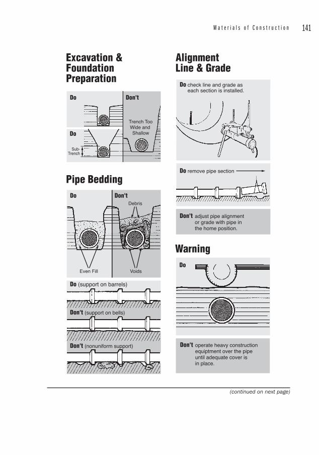
M a t e r i a l s o f C o n s t r u c t i o n 141
Do
Do
Don't
Do
Even Fill
Trench TooWide and Shallow
Sub-Trench
Voids
Debris
Don't
Don't (nonuniform support)
Don't (support on bells)
Do (support on barrels)
Don't adjust pipe alignment or grade with pipe in the home position.
Don't operate heavy constructionequiptment over the pipe until adequate cover is in place.
Do remove pipe section
Do
Do check line and grade as each section is installed.
Excavation & FoundationPreparation
AlignmentLine & Grade
Pipe Bedding
Warning
(continued on next page)
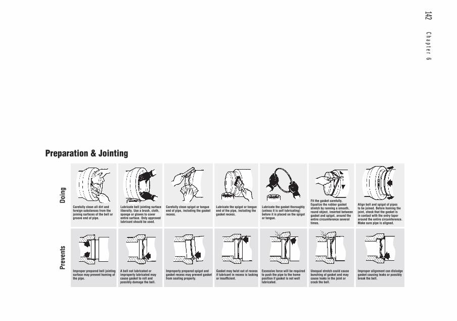
142 Chapter 6
Preparation & Jointing
Carefully clean all dirt and foreign substances from the joining surfaces of the bell or groove end of pipe.
Lubricate bell jointing surface liberally. Use a brush, cloth, sponge or gloves to cover entire surface. Only approved lubricant should be used.
Carefully clean spigot or tongue end of pipe, including the gasket recess.
Lubricate the spigot or tongue end of the pipe, including the gasket recess.
Lubricate the gasket thoroughly (unless it is self lubricating) before it is placed on the spigot or tongue.
Fit the gasket carefully. Equalize the rubber gasket stretch by running a smooth, round object, inserted between gasket and spigot, around the entire circumference several times.
Align bell and spigot of pipes to be joined. Before homing the joint, check that the gasket is in contact with the entry taper around the entire circumference. Make sure pipe is aligned.
Improper prepared bell jointing surface may prevent homing of the pipe.
A bell not lubricated or improperly lubricated may cause gasket to roll and possibly damage the bell.
Improperly prepared spigot and gasket recess may prevent gasket from sealing properly.
Gasket may twist out of recess if lubricant in recess is lacking or insufficient.
Excessive force will be required to push the pipe to the home position if gasket is not well lubricated.
Unequal stretch could cause bunching of gasket and may cause leaks in the joint or crack the bell.
Improper alignment can dislodge gasket causing leaks or possibly break the bell.
Doin
gPr
even
ts
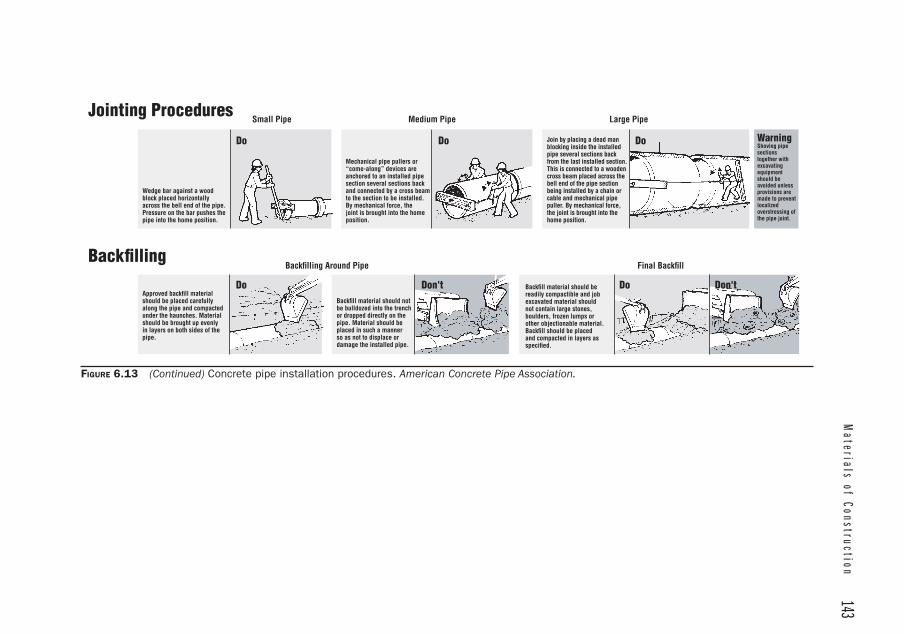
Materials of Construction
143
Do Do Do
Do Don't Do Don't
Jointing Procedures
Backfilling
Wedge bar against a wood block placed horizontally across the bell end of the pipe. Pressure on the bar pushes the pipe into the home position.
Mechanical pipe pullers or “come-along” devices are anchored to an installed pipe section several sections back and connected by a cross beam to the section to be installed. By mechanical force, the joint is brought into the home position.
Join by placing a dead man blocking inside the installed pipe several sections back from the last installed section. This is connected to a wooden cross beam placed across the bell end of the pipe section being installed by a chain or cable and mechanical pipe puller. By mechanical force, the joint is brought into the home position.
Approved backfill material should be placed carefully along the pipe and compacted under the haunches. Material should be brought up evenly in layers on both sides of the pipe.
Backfill material should not be bulldozed into the trench or dropped directly on the pipe. Material should be placed in such a manner so as not to displace or damage the installed pipe.
Backfill material should be readily compactible and job excavated material should not contain large stones, boulders, frozen lumps or other objectionable material. Backfill should be placed and compacted in layers as specified.
WarningShoving pipe sectionstogether with excavatingequipmentshould be avoided unless provisions are made to prevent localizedoverstressing of the pipe joint.
Small Pipe Medium Pipe Large Pipe
Backfilling Around Pipe Final Backfill
FIGURE 6.13 (Continued) Concrete pipe installation procedures. American Concrete Pipe Association.
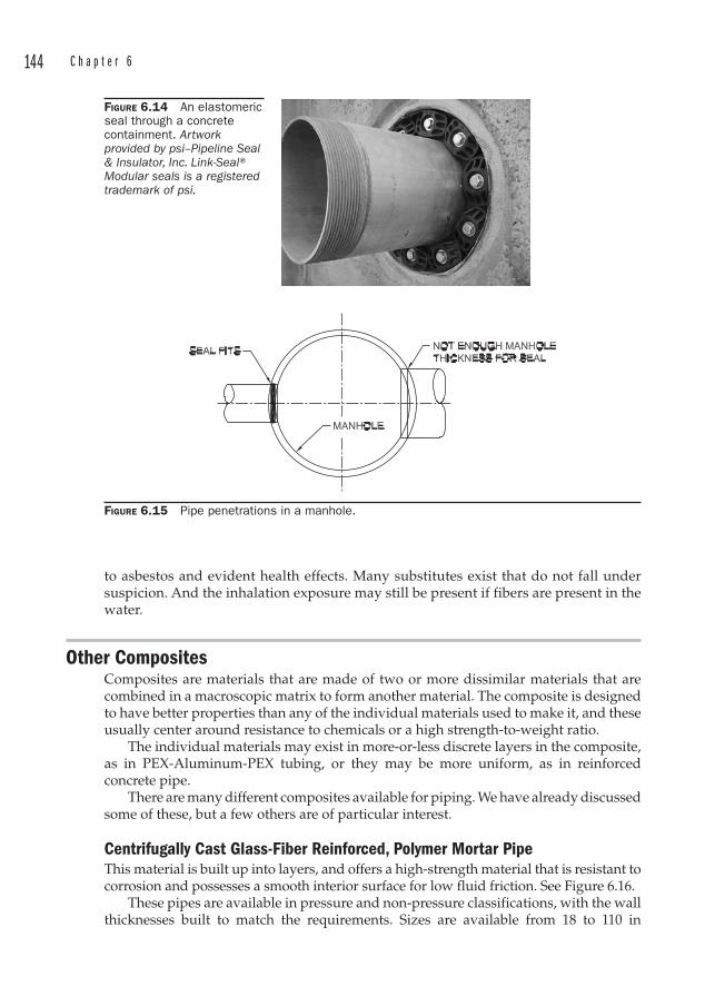
144 C h a p t e r 6
to asbestos and evident health effects. Many substitutes exist that do not fall under suspicion. And the inhalation exposure may still be present if fibers are present in the water.
Other Composites Composites are materials that are made of two or more dissimilar materials that are combined in a macroscopic matrix to form another material. The composite is designed to have better properties than any of the individual materials used to make it, and these usually center around resistance to chemicals or a high strength-to-weight ratio.
The individual materials may exist in more-or-less discrete layers in the composite, as in PEX -Aluminum-PEX tubing, or they may be more uniform, as in reinforced concrete pipe.
There are many different composites available for piping. We have already discussed some of these, but a few others are of particular interest.
Centrifugally Cast Glass-Fiber Reinforced, Polymer Mortar Pipe This material is built up into layers, and offers a high-strength material that is resistant to corrosion and possesses a smooth interior surface for low fluid friction. See Figure 6.16.
These pipes are available in pressure and non-pressure classifications, with the wall thicknesses built to match the requirements. Sizes are available from 18 to 110 in
FIGURE 6.14 An elastomeric seal through a concrete containment. Artwork provided by psi–Pipeline Seal & Insulator, Inc. Link-Seal® Modular seals is a registered trademark of psi.
FIGURE 6.15 Pipe penetrations in a manhole.
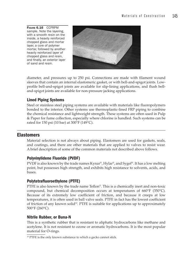
M a t e r i a l s o f C o n s t r u c t i o n 145
diameter, and pressures up to 250 psi. Connections are made with filament wound sleeves that contain an internal elastomeric gasket, or with bell-and-spigot joints. Low-profile bell-and-spigot joints are available for slip-lining applications, and flush bell-and-spigot joints are available for non-pressure jacking applications.
Lined Piping SystemsSteel or stainless steel piping systems are available with materials like fluoropolymers bonded to the interior. Other systems use thermoplastic-lined FRP piping to combine the chemical resistance and lightweight strength. These systems are often used in Pulp & Paper for fume collection, especially where chlorine is handled. Such systems can be rated for 150 psi (10 bar) at 300°F (149°C).
ElastomersMaterial selection is not always about piping. Elastomers are used for gaskets, seals, and coatings, and there are other materials that are applied to valves to resist wear. A brief description of some of the common materials not described above follows.
Polyvinylidene Fluoride (PVDF )PVDF is also known by the trade names Kynar® , Hylar®, and Sygef®. It has a low melting point, but possesses high strength, and exhibits high resistance to solvents, acids, and bases.
Polytetrafluoroethylene (PTFE )PTFE is also known by the trade name Teflon®. This is a chemically inert and non-toxic compound, but chemical decomposition occurs at temperatures of 660°F (350°C). Because of its extremely low coefficient of friction, and because it creeps at low temperatures, it is often used in ball valve seals. PTFE in fact has the lowest coefficient of friction of any known solid10. PTFE is suitable for applications up to approximately 500°F (260°C).
Nitrile Rubber, or Buna-N This is a synthetic rubber that is resistant to aliphatic hydrocarbons like methane and acetylene. It is not resistant to ozone or aromatic hydrocarbons. It is the most popular material for O-rings.10 PTFE is the only known substance to which a gecko cannot stick.
FIGURE 6.16 CCFRPMsample. Note the layering, with a smooth resin on the inside, a heavily reinforced chopped glass and mortar layer, a core of polymer mortar, followed by another heavily reinforced layer of chopped glass and resin, and fi nally, an exterior layer of sand and resin.
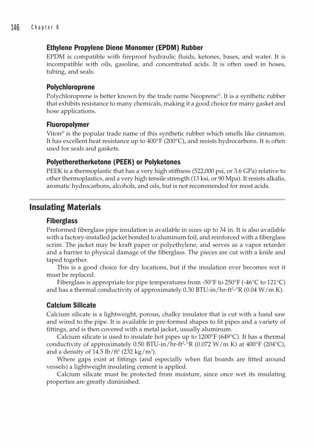
146 C h a p t e r 6
Ethylene Propylene Diene Monomer (EPDM ) Rubber EPDM is compatible with fireproof hydraulic fluids, ketones, bases, and water. It is incompatible with oils, gasoline, and concentrated acids. It is often used in hoses, tubing, and seals.
Polychloroprene Polychloroprene is better known by the trade name Neoprene® . It is a synthetic rubber that exhibits resistance to many chemicals, making it a good choice for many gasket and hose applications.
FluoropolymerViton® is the popular trade name of this synthetic rubber which smells like cinnamon. It has excellent heat resistance up to 400°F (200°C), and resists hydrocarbons. It is often used for seals and gaskets.
Polyetheretherketone (PEEK ) or PolyketonesPEEK is a thermoplastic that has a very high stiffness (522,000 psi, or 3.6 GPa) relative to other thermoplastics, and a very high tensile strength (13 ksi, or 90 Mpa). It resists alkalis, aromatic hydrocarbons, alcohols, and oils, but is not recommended for most acids.
Insulating Materials Fiberglass Preformed fiberglass pipe insulation is available in sizes up to 34 in. It is also available with a factory-installed jacket bonded to aluminum foil, and reinforced with a fiberglass scrim. The jacket may be kraft paper or polyethylene, and serves as a vapor retarder and a barrier to physical damage of the fiberglass. The pieces are cut with a knife and taped together.
This is a good choice for dry locations, but if the insulation ever becomes wet it must be replaced.
Fiberglass is appropriate for pipe temperatures from -50°F to 250°F (-46°C to 121°C) and has a thermal conductivity of approximately 0.30 BTU-in/hr-ft2-°R (0.04 W/m K).
Calcium Silicate Calcium silicate is a lightweight, porous, chalky insulator that is cut with a hand saw and wired to the pipe. It is available in pre-formed shapes to fit pipes and a variety of fittings, and is then covered with a metal jacket, usually aluminum.
Calcium silicate is used to insulate hot pipes up to 1200°F (649°C). It has a thermal conductivity of approximately 0.50 BTU-in/hr-ft2-°R (0.072 W/m K) at 400°F (204°C), and a density of 14.5 lb/ft3 (232 kg/m3).
Where gaps exist at fittings (and especially when flat boards are fitted around vessels) a lightweight insulating cement is applied.
Calcium silicate must be protected from moisture, since once wet its insulating properties are greatly diminished.
M a t e r i a l s o f C o n s t r u c t i o n 147
Cellular Glass Cellular glass is a closed-cell material that is used in applications from -450°F to 900°F (-268°C to 482°C). Being a closed-cell material, it is an excellent choice for locations subject to moisture. It is impermeable to liquids and it does not burn. It may also be used for underground applications, and is available in a wide range of preformed shapes.
Cellular glass has a thermal conductivity of 0.29 BTU-in/hr-ft2-°R (0.039 W/m K) at 75°F (24°C) and a density of 7.5 lb/ft3 (120 kg/m3).
Foam Synthetic Rubber Preformed foam synthetic rubber insulation is available in sizes up to 6 in NPS. It is used primarily for plumbing and hydronics applications, and has a recommended temperature range of -297°F to 220°F (-183°C to 105°C). It is often used to prevent condensation on cold service piping.
It is slipped over or slit and wrapped around the pipe. Butt joints and seams are sealed with a special adhesive. Foam synthetic rubber is designed for above ground installations only. If exposed to weather, a protective finish must be applied to protect it from ultraviolet degradation.
Foam synthetic rubber has a thermal conductivity of 0.27 BTU-in/hr-ft2-°R (0.039 W/m K) at 75°F (24°C) and a density of 3 to 6 lb/ft3 (48 to 96 kg/m3).
Polyisocyanurate This is a cellular polymer insulation for use at temperatures from -297°F to 300°F (-183°C to 149°C). It may be used for general industrial piping, chilled water, or tank and vessel insulation. Polyisocyanurate will degrade when exposed to the ultraviolet spectrum, so a covering is required for locations exposed to sunlight. Polyisocyanurate is combustible, but certain manufacturers are able to attain a Flame Spread Index of 25 or less, and a Smoke Developed Index of 50 or less.
Polyisocyanurate has a thermal conductivity of 0.19 BTU-in/hr-ft2-°R (0.027W/m K) at 75°F (24°C) and a density of 2.05 lb/ft3 (32.8 kg/m3).
Mineral Wool Mineral wool insulation is suitable for temperature ranges up to 1200°F (1177°C). It is made from basalt rock and steel slag with an organic binder. The binder requires that a heat-up schedule be maintained for service temperatures above 450°F (232°C). During this heat-up phase, some of the resin will start a controlled decomposition so adequate ventilation is required to vent vapors.
Mineral wool is water repellant, yet vapor-permeable, and it may be used outdoors. A metal jacket is recommended to protect the insulation from physical damage as well as weatherproofing. The insulation is cut with a knife and wired to the pipe. Nesting schedules are available to provide increased insulation thicknesses.
While there is no known carcinogenic risk of inhaling the fibers, OSHA has established exposure limits for inhalation, and respiratory protection is required during installation.
Mineral wool has a thermal conductivity of 0.25 BTU-in/hr-ft2-°R (0.035 W/m K) at 100°F (24°C) and a density of 4.4 lb/ft3 (70 kg/m3).

148 C h a p t e r 6
Extruded Polystyrene Extruded polystyrene is a rigid thermoplastic foam insulator that is used for piping in the range of -297°F to 165°F (-183°C to 74°C). It is most often used for cold lines to prevent heat gain and surface condensation or sweating. It will degrade when exposed to sunlight if not covered.
At least one manufacturer includes a fire retardant to inhibit accidental ignition, but the Smoke Developed Index may be as high as 165.
Extruded polystyrene has a thermal conductivity of 0.259 BTU-in/hr-ft2-°R (0.037W/m K) at 75°F (24°C) and a density of 1.6 lb/ft3 (26 kg/m3).
149
CHAPTER 7Fittings
Piping systems require fittings in order to change direction and connect to all of the equipment and devices required to make them function. These fittings are manufactured in standard dimensions referred to as the fitting “take-out. ” See
Table 7.1. Virtually any piping component that attaches permanently to a pipe can be considered a fitting.
Fittings must obviously be manufactured for every type of pipe and every type of connection, i.e., threaded, flanged, or welded. Socket welded and threaded fittings are available in sizes up to 4 in diameter, but are not commonly used in sizes above 2 in diameter.1
Fittings may be classified according to their material of construction or according to their function. The various standard specifications for fittings are generally classified according to MOC. In this chapter however, we will examine the fittings by function and purpose. The variety of fittings is staggering since there are so many combinations of materials and functions. A trip through the plumbing section of a home improvement center will impress upon the reader the number of choices that exist in connecting two pieces of pipe together. And that is just residential plumbing.
Common fittings include:
• Flanges
• Elbows (90 and 45°) and reducing elbows
• Tees , reducing tees, and cleanouts
• Unions
• Laterals
• Reducers (concentric, eccentric)
• Caps
• Plugs
• Nipples, couplings, and half-couplings.
Less common fittings are:
• Swages
• Bull plugs
• Crosses
• Wyes
1 This coincides with the typical sizes regarded as field-routed piping, so “field-routed” generally implies threaded or socket welded pipe.
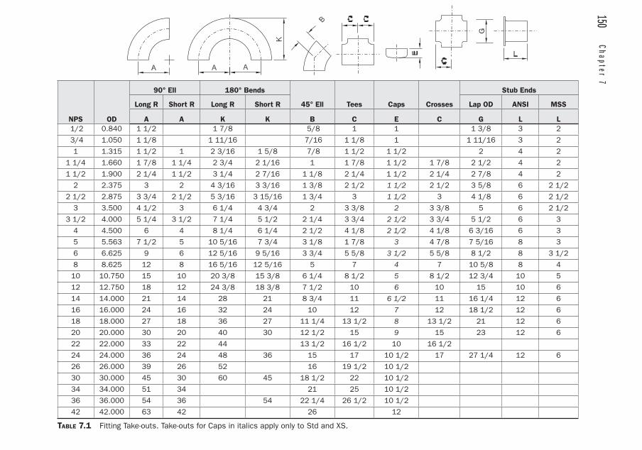
150 Chapter 7
NPS OD
90° Ell 180° Bends
45° Ell Tees Caps Crosses
Stub Ends
Long R Short R Long R Short R Lap OD ANSI MSS
A A K K B C E C G L L 1/2 0.840 1 1/2 1 7/8 5/8 1 1 1 3/8 3 2
3/4 1.050 1 1/8 1 11/16 7/16 1 1/8 1 1 11/16 3 2
1 1.315 1 1/2 1 2 3/16 1 5/8 7/8 1 1/2 1 1/2 2 4 2
1 1/4 1.660 1 7/8 1 1/4 2 3/4 2 1/16 1 1 7/8 1 1/2 1 7/8 2 1/2 4 2
1 1/2 1.900 2 1/4 1 1/2 3 1/4 2 7/16 1 1/8 2 1/4 1 1/2 2 1/4 2 7/8 4 2
2 2.375 3 2 4 3/16 3 3/16 1 3/8 2 1/2 1 1/2 2 1/2 3 5/8 6 2 1/2
2 1/2 2.875 3 3/4 2 1/2 5 3/16 3 15/16 1 3/4 3 1 1/2 3 4 1/8 6 2 1/2
3 3.500 4 1/2 3 6 1/4 4 3/4 2 3 3/8 2 3 3/8 5 6 2 1/2
3 1/2 4.000 5 1/4 3 1/2 7 1/4 5 1/2 2 1/4 3 3/4 2 1/2 3 3/4 5 1/2 6 3
4 4.500 6 4 8 1/4 6 1/4 2 1/2 4 1/8 2 1/2 4 1/8 6 3/16 6 3
5 5.563 7 1/2 5 10 5/16 7 3/4 3 1/8 1 7/8 3 4 7/8 7 5/16 8 3
6 6.625 9 6 12 5/16 9 5/16 3 3/4 5 5/8 3 1/2 5 5/8 8 1/2 8 3 1/2
8 8.625 12 8 16 5/16 12 5/16 5 7 4 7 10 5/8 8 4
10 10.750 15 10 20 3/8 15 3/8 6 1/4 8 1/2 5 8 1/2 12 3/4 10 5
12 12.750 18 12 24 3/8 18 3/8 7 1/2 10 6 10 15 10 6
14 14.000 21 14 28 21 8 3/4 11 6 1/2 11 16 1/4 12 6
16 16.000 24 16 32 24 10 12 7 12 18 1/2 12 6
18 18.000 27 18 36 27 11 1/4 13 1/2 8 13 1/2 21 12 6
20 20.000 30 20 40 30 12 1/2 15 9 15 23 12 6
22 22.000 33 22 44 13 1/2 16 1/2 10 16 1/2
24 24.000 36 24 48 36 15 17 10 1/2 17 27 1/4 12 6
26 26.000 39 26 52 16 19 1/2 10 1/2
30 30.000 45 30 60 45 18 1/2 22 10 1/2
34 34.000 51 34 21 25 10 1/2
36 36.000 54 36 54 22 1/4 26 1/2 10 1/2
42 42.000 63 42 26 12
TABLE 7.1 Fitting Take-outs. Take-outs for Caps in italics apply only to Std and XS.
G
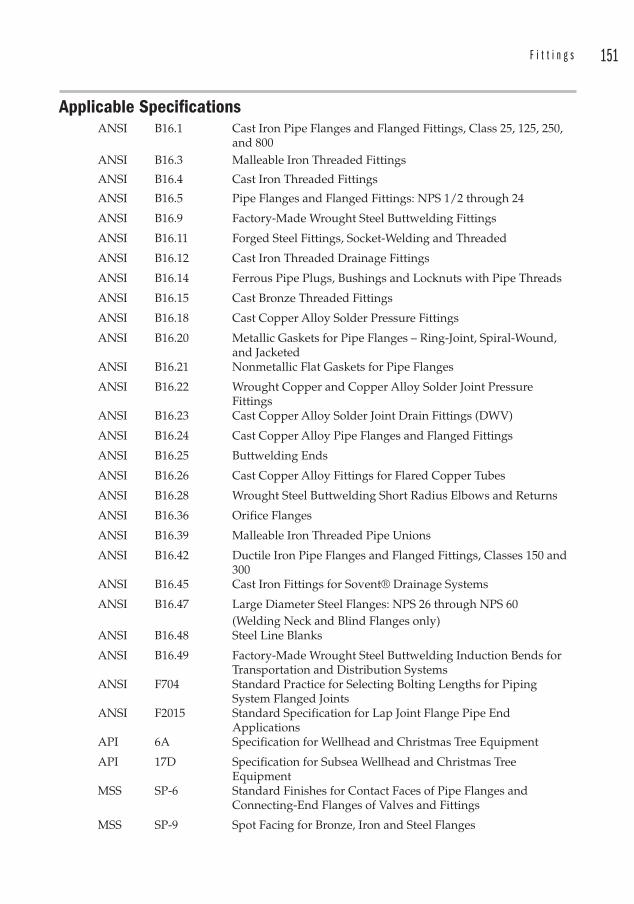
F i t t i n g s 151
Applicable SpecificationsANSI B16.1 Cast Iron Pipe Flanges and Flanged Fittings, Class 25, 125, 250,
and 800ANSI B16.3 Malleable Iron Threaded Fittings
ANSI B16.4 Cast Iron Threaded Fittings
ANSI B16.5 Pipe Flanges and Flanged Fittings: NPS 1/2 through 24
ANSI B16.9 Factory-Made Wrought Steel Buttwelding Fittings
ANSI B16.11 Forged Steel Fittings, Socket-Welding and Threaded
ANSI B16.12 Cast Iron Threaded Drainage Fittings
ANSI B16.14 Ferrous Pipe Plugs , Bushings and Locknuts with Pipe Threads
ANSI B16.15 Cast Bronze Threaded Fittings
ANSI B16.18 Cast Copper Alloy Solder Pressure Fittings
ANSI B16.20 Metallic Gaskets for Pipe Flanges – Ring-Joint, Spiral-Wound, and Jacketed
ANSI B16.21 Nonmetallic Flat Gaskets for Pipe Flanges
ANSI B16.22 Wrought Copper and Copper Alloy Solder Joint Pressure Fittings
ANSI B16.23 Cast Copper Alloy Solder Joint Drain Fittings (DWV)
ANSI B16.24 Cast Copper Alloy Pipe Flanges and Flanged Fittings
ANSI B16.25 Buttwelding Ends
ANSI B16.26 Cast Copper Alloy Fittings for Flared Copper Tubes
ANSI B16.28 Wrought Steel Buttwelding Short Radius Elbows and Returns
ANSI B16.36 Orifice Flanges
ANSI B16.39 Malleable Iron Threaded Pipe Unions
ANSI B16.42 Ductile Iron Pipe Flanges and Flanged Fittings, Classes 150 and 300
ANSI B16.45 Cast Iron Fittings for Sovent® Drainage Systems
ANSI B16.47 Large Diameter Steel Flanges: NPS 26 through NPS 60(Welding Neck and Blind Flanges only)
ANSI B16.48 Steel Line Blanks
ANSI B16.49 Factory-Made Wrought Steel Buttwelding Induction Bends for Transportation and Distribution Systems
ANSI F704 Standard Practice for Selecting Bolting Lengths for Piping System Flanged Joints
ANSI F2015 Standard Specification for Lap Joint Flange Pipe End Applications
API 6A Specification for Wellhead and Christmas Tree Equipment
API 17D Specification for Subsea Wellhead and Christmas Tree Equipment
MSS SP-6 Standard Finishes for Contact Faces of Pipe Flanges and Connecting-End Flanges of Valves and Fittings
MSS SP-9 Spot Facing for Bronze, Iron and Steel Flanges
152 C h a p t e r 7
MSS SP-44 Steel Pipeline Flanges
MSS SP-60 Connecting Flange Joint Between Tapping Sleeves and Tapping Valves
MSS SP-65 High Pressure Chemical Industry Flanges and Threaded Stubs for Use with Lens Gaskets
MSS SP-95 Swaged Nipples and Bull Plugs
MSS SP-97 Integrally Reinforced Forged Branch Outlet Fittings - Socket Welding, Threaded and Buttwelding Ends
SAE J518 Hydraulic Flanged Tube, Pipe, and Hose Connections, Four-Bolt Split Flange Type
FlangesThere are several styles of flanges in use. For hydraulic service, SAE J518 4-bolt flanges are common. However, for industrial, commercial, and institutional applications the most commonly used flanges conform to the requirements of ANSI B16.5. These flanges are available in a variety of styles and pressure classes. The dimensions of these flanges are tabulated in Tables 7.2 through 7.5.
Flanges are not recommended for use in underground service where the flange will be in direct contact with soil, since this opens the possibility for corrosion of bolted connections. Where it is necessary to use a flange in underground service, as at a valve, it is preferred to have the flanged connection exposed in a valve pit for maintenance access.
Flange Ratings The allowable pressures for a given class are material and temperature dependent. Thus, for a 150 lb carbon steel flange, the allowable pressure is 275 psi at 100°F, 150 psi at 500°F, and 40 psi at 1000°F. The only temperature at which the flange is rated for 150 psi is 500°F. Heavier flanges are rated at their nominal pressure rating only at 850°F.
Pressure classes of cast iron flanges are established in ANSI B16.1; pressure classes for other flanges are established by ANSI B16.5. The pressure classes of flanges are commonly referred to in terms of “pounds” rather than “pounds per square inch.” But because the allowable pressures are the same as the nominal pressure classes only at the elevated temperatures noted above, it is best to think of the pressure classes as nominal values, and not as “pressures.” The pressures and temperatures do not correspond to saturated steam properties, as is sometimes thought.
Although ANSI now refers to the pressure ratings as “classes,” the use of the term “pound” remains prevalent in the industry. In describing the pressure class of flanges, the terms “pound” and “class” may be considered interchangeable.
Further, it is important to note that the pressures listed in the ANSI B16.1 and B16.5 tables are for non-shock pressures. Tables 7.6 and 7.7 show the non-shock pressure and temperature ratings for cast iron and carbon steel flanges respectively.
Note that ANSI B16.1 permits cast iron flanges to be used in gaseous and steam service. This is a carry-over from the days when cast iron piping was prevalent in infrastructure and heating. Cast iron would not be the choice for steam or gaseous service today. Always use carbon or stainless steel for gaseous or steam services.
Materials for flanges are grouped into 24 categories in an effort to combine materials that are likely to be joined together. However, if two dissimilar groupings are mated, the lower rating of the two must be used.
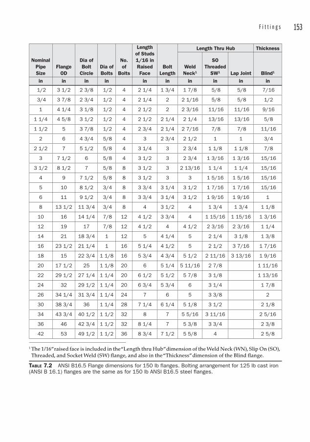
F i t t i n g s 153
NominalPipeSize
FlangeOD
Dia of Bolt
CircleDia of Bolts
No.of
Bolts
Lengthof Studs 1/16 in RaisedFace
BoltLength
Length Thru Hub Thickness
Weld Neck1
SOThreaded
SW1 Lap Joint Blind1
in in in in in in in in in in
1/2 3 1/2 2 3/8 1/2 4 2 1/4 1 3/4 1 7/8 5/8 5/8 7/16
3/4 3 7/8 2 3/4 1/2 4 2 1/4 2 2 1/16 5/8 5/8 1/2
1 4 1/4 3 1/8 1/2 4 2 1/2 2 2 3/16 11/16 11/16 9/16
1 1/4 4 5/8 3 1/2 1/2 4 2 1/2 2 1/4 2 1/4 13/16 13/16 5/8
1 1/2 5 3 7/8 1/2 4 2 3/4 2 1/4 2 7/16 7/8 7/8 11/16
2 6 4 3/4 5/8 4 3 2 3/4 2 1/2 1 1 3/4
2 1/2 7 5 1/2 5/8 4 3 1/4 3 2 3/4 1 1/8 1 1/8 7/8
3 7 1/2 6 5/8 4 3 1/2 3 2 3/4 1 3/16 1 3/16 15/16
3 1/2 8 1/2 7 5/8 8 3 1/2 3 2 13/16 1 1/4 1 1/4 15/16
4 9 7 1/2 5/8 8 3 1/2 3 3 1 5/16 1 5/16 15/16
5 10 8 1/2 3/4 8 3 3/4 3 1/4 3 1/2 1 7/16 1 7/16 15/16
6 11 9 1/2 3/4 8 3 3/4 3 1/4 3 1/2 1 9/16 1 9/16 1
8 13 1/2 11 3/4 3/4 8 4 3 1/2 4 1 3/4 1 3/4 1 1/8
10 16 14 1/4 7/8 12 4 1/2 3 3/4 4 1 15/16 1 15/16 1 3/16
12 19 17 7/8 12 4 1/2 4 4 1/2 2 3/16 2 3/16 1 1/4
14 21 18 3/4 1 12 5 4 1/4 5 2 1/4 3 1/8 1 3/8
16 23 1/2 21 1/4 1 16 5 1/4 4 1/2 5 2 1/2 3 7/16 1 7/16
18 15 22 3/4 1 1/8 16 5 3/4 4 3/4 5 1/2 2 11/16 3 13/16 1 9/16
20 17 1/2 25 1 1/8 20 6 5 1/4 5 11/16 2 7/8 1 11/16
22 29 1/2 27 1/4 1 1/4 20 6 1/2 5 1/2 5 7/8 3 1/8 1 13/16
24 32 29 1/2 1 1/4 20 6 3/4 5 3/4 6 3 1/4 1 7/8
26 34 1/4 31 3/4 1 1/4 24 7 6 5 3 3/8 2
30 38 3/4 36 1 1/4 28 7 1/4 6 1/4 5 1/8 3 1/2 2 1/8
34 43 3/4 40 1/2 1 1/2 32 8 7 5 5/16 3 11/16 2 5/16
36 46 42 3/4 1 1/2 32 8 1/4 7 5 3/8 3 3/4 2 3/8
42 53 49 1/2 1 1/2 36 8 3/4 7 1/2 5 5/8 4 2 5/8
1 The 1/16” raised face is included in the “Length thru Hub” dimension of the Weld Neck (WN), Slip On (SO), Threaded, and Socket Weld (SW) flange, and also in the “Thickness” dimension of the Blind flange.
TABLE 7.2 ANSI B16.5 Flange dimensions for 150 lb flanges. Bolting arrangement for 125 lb cast iron (ANSI B 16.1) flanges are the same as for 150 lb ANSI B16.5 steel flanges.
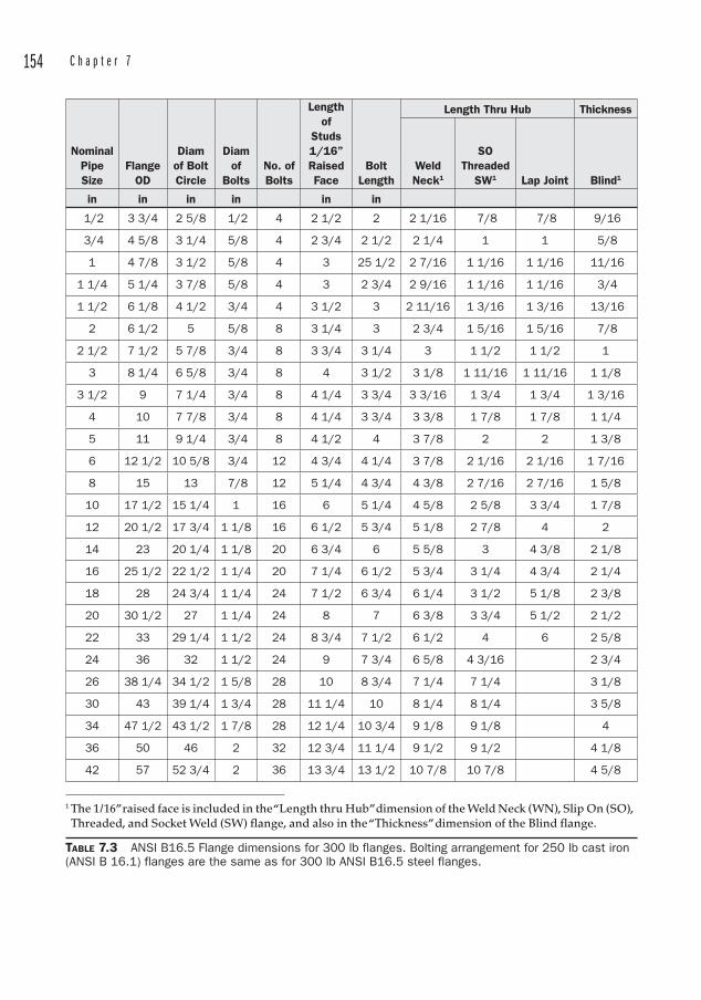
154 C h a p t e r 7
NominalPipeSize
FlangeOD
Diamof Bolt Circle
Diamof
BoltsNo. of Bolts
Lengthof
Studs1/16”RaisedFace
BoltLength
Length Thru Hub Thickness
Weld Neck1
SOThreaded
SW1 Lap Joint Blind1
in in in in in in
1/2 3 3/4 2 5/8 1/2 4 2 1/2 2 2 1/16 7/8 7/8 9/16
3/4 4 5/8 3 1/4 5/8 4 2 3/4 2 1/2 2 1/4 1 1 5/8
1 4 7/8 3 1/2 5/8 4 3 25 1/2 2 7/16 1 1/16 1 1/16 11/16
1 1/4 5 1/4 3 7/8 5/8 4 3 2 3/4 2 9/16 1 1/16 1 1/16 3/4
1 1/2 6 1/8 4 1/2 3/4 4 3 1/2 3 2 11/16 1 3/16 1 3/16 13/16
2 6 1/2 5 5/8 8 3 1/4 3 2 3/4 1 5/16 1 5/16 7/8
2 1/2 7 1/2 5 7/8 3/4 8 3 3/4 3 1/4 3 1 1/2 1 1/2 1
3 8 1/4 6 5/8 3/4 8 4 3 1/2 3 1/8 1 11/16 1 11/16 1 1/8
3 1/2 9 7 1/4 3/4 8 4 1/4 3 3/4 3 3/16 1 3/4 1 3/4 1 3/16
4 10 7 7/8 3/4 8 4 1/4 3 3/4 3 3/8 1 7/8 1 7/8 1 1/4
5 11 9 1/4 3/4 8 4 1/2 4 3 7/8 2 2 1 3/8
6 12 1/2 10 5/8 3/4 12 4 3/4 4 1/4 3 7/8 2 1/16 2 1/16 1 7/16
8 15 13 7/8 12 5 1/4 4 3/4 4 3/8 2 7/16 2 7/16 1 5/8
10 17 1/2 15 1/4 1 16 6 5 1/4 4 5/8 2 5/8 3 3/4 1 7/8
12 20 1/2 17 3/4 1 1/8 16 6 1/2 5 3/4 5 1/8 2 7/8 4 2
14 23 20 1/4 1 1/8 20 6 3/4 6 5 5/8 3 4 3/8 2 1/8
16 25 1/2 22 1/2 1 1/4 20 7 1/4 6 1/2 5 3/4 3 1/4 4 3/4 2 1/4
18 28 24 3/4 1 1/4 24 7 1/2 6 3/4 6 1/4 3 1/2 5 1/8 2 3/8
20 30 1/2 27 1 1/4 24 8 7 6 3/8 3 3/4 5 1/2 2 1/2
22 33 29 1/4 1 1/2 24 8 3/4 7 1/2 6 1/2 4 6 2 5/8
24 36 32 1 1/2 24 9 7 3/4 6 5/8 4 3/16 2 3/4
26 38 1/4 34 1/2 1 5/8 28 10 8 3/4 7 1/4 7 1/4 3 1/8
30 43 39 1/4 1 3/4 28 11 1/4 10 8 1/4 8 1/4 3 5/8
34 47 1/2 43 1/2 1 7/8 28 12 1/4 10 3/4 9 1/8 9 1/8 4
36 50 46 2 32 12 3/4 11 1/4 9 1/2 9 1/2 4 1/8
42 57 52 3/4 2 36 13 3/4 13 1/2 10 7/8 10 7/8 4 5/8
1 The 1/16” raised face is included in the “Length thru Hub” dimension of the Weld Neck (WN), Slip On (SO), Threaded, and Socket Weld (SW) flange, and also in the “Thickness” dimension of the Blind flange.
TABLE 7.3 ANSI B16.5 Flange dimensions for 300 lb flanges. Bolting arrangement for 250 lb cast iron (ANSI B 16.1) flanges are the same as for 300 lb ANSI B16.5 steel flanges.
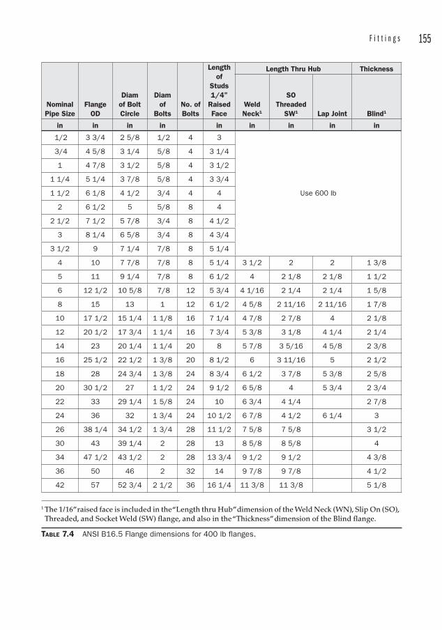
F i t t i n g s 155
NominalPipe Size
FlangeOD
Diamof Bolt Circle
Diamof
BoltsNo. of Bolts
Lengthof
Studs1/4”
RaisedFace
Length Thru Hub Thickness
Weld Neck1
SOThreaded
SW1 Lap Joint Blind1
in in in in in in in in in
1/2 3 3/4 2 5/8 1/2 4 3
Use 600 lb
3/4 4 5/8 3 1/4 5/8 4 3 1/4
1 4 7/8 3 1/2 5/8 4 3 1/2
1 1/4 5 1/4 3 7/8 5/8 4 3 3/4
1 1/2 6 1/8 4 1/2 3/4 4 4
2 6 1/2 5 5/8 8 4
2 1/2 7 1/2 5 7/8 3/4 8 4 1/2
3 8 1/4 6 5/8 3/4 8 4 3/4
3 1/2 9 7 1/4 7/8 8 5 1/4
4 10 7 7/8 7/8 8 5 1/4 3 1/2 2 2 1 3/8
5 11 9 1/4 7/8 8 6 1/2 4 2 1/8 2 1/8 1 1/2
6 12 1/2 10 5/8 7/8 12 5 3/4 4 1/16 2 1/4 2 1/4 1 5/8
8 15 13 1 12 6 1/2 4 5/8 2 11/16 2 11/16 1 7/8
10 17 1/2 15 1/4 1 1/8 16 7 1/4 4 7/8 2 7/8 4 2 1/8
12 20 1/2 17 3/4 1 1/4 16 7 3/4 5 3/8 3 1/8 4 1/4 2 1/4
14 23 20 1/4 1 1/4 20 8 5 7/8 3 5/16 4 5/8 2 3/8
16 25 1/2 22 1/2 1 3/8 20 8 1/2 6 3 11/16 5 2 1/2
18 28 24 3/4 1 3/8 24 8 3/4 6 1/2 3 7/8 5 3/8 2 5/8
20 30 1/2 27 1 1/2 24 9 1/2 6 5/8 4 5 3/4 2 3/4
22 33 29 1/4 1 5/8 24 10 6 3/4 4 1/4 2 7/8
24 36 32 1 3/4 24 10 1/2 6 7/8 4 1/2 6 1/4 3
26 38 1/4 34 1/2 1 3/4 28 11 1/2 7 5/8 7 5/8 3 1/2
30 43 39 1/4 2 28 13 8 5/8 8 5/8 4
34 47 1/2 43 1/2 2 28 13 3/4 9 1/2 9 1/2 4 3/8
36 50 46 2 32 14 9 7/8 9 7/8 4 1/2
42 57 52 3/4 2 1/2 36 16 1/4 11 3/8 11 3/8 5 1/8
1 The 1/16” raised face is included in the “Length thru Hub” dimension of the Weld Neck (WN), Slip On (SO), Threaded, and Socket Weld (SW) flange, and also in the “Thickness” dimension of the Blind flange.
TABLE 7.4 ANSI B16.5 Flange dimensions for 400 lb flanges.
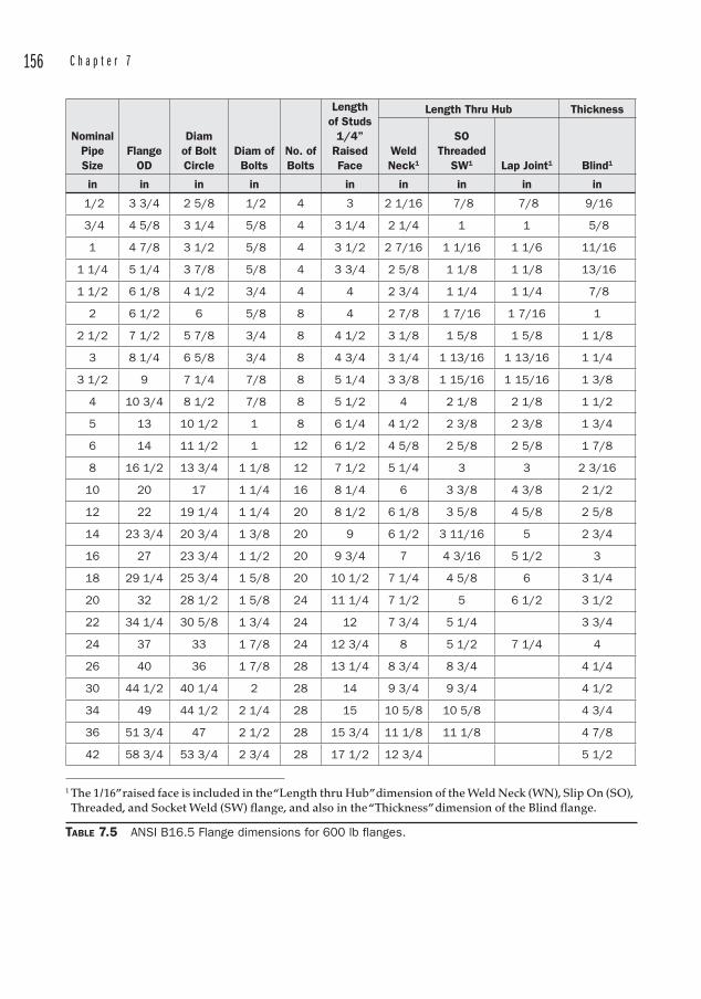
156 C h a p t e r 7
NominalPipeSize
FlangeOD
Diamof Bolt Circle
Diam of Bolts
No. of Bolts
Lengthof Studs
1/4”RaisedFace
Length Thru Hub Thickness
Weld Neck1
SOThreaded
SW1 Lap Joint1 Blind1
in in in in in in in in in
1/2 3 3/4 2 5/8 1/2 4 3 2 1/16 7/8 7/8 9/16
3/4 4 5/8 3 1/4 5/8 4 3 1/4 2 1/4 1 1 5/8
1 4 7/8 3 1/2 5/8 4 3 1/2 2 7/16 1 1/16 1 1/6 11/16
1 1/4 5 1/4 3 7/8 5/8 4 3 3/4 2 5/8 1 1/8 1 1/8 13/16
1 1/2 6 1/8 4 1/2 3/4 4 4 2 3/4 1 1/4 1 1/4 7/8
2 6 1/2 6 5/8 8 4 2 7/8 1 7/16 1 7/16 1
2 1/2 7 1/2 5 7/8 3/4 8 4 1/2 3 1/8 1 5/8 1 5/8 1 1/8
3 8 1/4 6 5/8 3/4 8 4 3/4 3 1/4 1 13/16 1 13/16 1 1/4
3 1/2 9 7 1/4 7/8 8 5 1/4 3 3/8 1 15/16 1 15/16 1 3/8
4 10 3/4 8 1/2 7/8 8 5 1/2 4 2 1/8 2 1/8 1 1/2
5 13 10 1/2 1 8 6 1/4 4 1/2 2 3/8 2 3/8 1 3/4
6 14 11 1/2 1 12 6 1/2 4 5/8 2 5/8 2 5/8 1 7/8
8 16 1/2 13 3/4 1 1/8 12 7 1/2 5 1/4 3 3 2 3/16
10 20 17 1 1/4 16 8 1/4 6 3 3/8 4 3/8 2 1/2
12 22 19 1/4 1 1/4 20 8 1/2 6 1/8 3 5/8 4 5/8 2 5/8
14 23 3/4 20 3/4 1 3/8 20 9 6 1/2 3 11/16 5 2 3/4
16 27 23 3/4 1 1/2 20 9 3/4 7 4 3/16 5 1/2 3
18 29 1/4 25 3/4 1 5/8 20 10 1/2 7 1/4 4 5/8 6 3 1/4
20 32 28 1/2 1 5/8 24 11 1/4 7 1/2 5 6 1/2 3 1/2
22 34 1/4 30 5/8 1 3/4 24 12 7 3/4 5 1/4 3 3/4
24 37 33 1 7/8 24 12 3/4 8 5 1/2 7 1/4 4
26 40 36 1 7/8 28 13 1/4 8 3/4 8 3/4 4 1/4
30 44 1/2 40 1/4 2 28 14 9 3/4 9 3/4 4 1/2
34 49 44 1/2 2 1/4 28 15 10 5/8 10 5/8 4 3/4
36 51 3/4 47 2 1/2 28 15 3/4 11 1/8 11 1/8 4 7/8
42 58 3/4 53 3/4 2 3/4 28 17 1/2 12 3/4 5 1/2
1 The 1/16” raised face is included in the “Length thru Hub” dimension of the Weld Neck (WN), Slip On (SO), Threaded, and Socket Weld (SW) flange, and also in the “Thickness” dimension of the Blind flange.
TABLE 7.5 ANSI B16.5 Flange dimensions for 600 lb flanges.
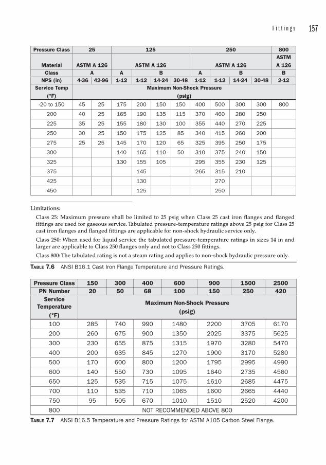
F i t t i n g s 157
Pressure Class 25 125 250 800
Material ASTM A 126 ASTM A 126 ASTM A 126ASTMA 126
Class A A B A B BNPS (in) 4-36 42-96 1-12 1-12 14-24 30-48 1-12 1-12 14-24 30-48 2-12
Service Temp(°F)
Maximum Non-Shock Pressure(psig)
-20 to 150 45 25 175 200 150 150 400 500 300 300 800
200 40 25 165 190 135 115 370 460 280 250
225 35 25 155 180 130 100 355 440 270 225
250 30 25 150 175 125 85 340 415 260 200
275 25 25 145 170 120 65 325 395 250 175
300 140 165 110 50 310 375 240 150
325 130 155 105 295 355 230 125
375 145 265 315 210
425 130 270
450 125 250
Limitations:
Class 25: Maxi mum pressure shall be limited to 25 psig when Class 25 cast iron flanges and flanged fittings are used for gaseous service. Tabulated pressure-temperature ratings above 25 psig for Class 25 cast iron flanges and flanged fittings are applicable for non-shock hydraulic service only.
Class 250: When used for liquid service the tabulated pressure-temperature ratings in sizes 14 in and larger are applicable to Class 250 flanges only and not to Class 250 fittings.
Class 800: The tabulated rating is not a steam rating and applies to non-shock hydraulic pressure only.
TABLE 7.6 ANSI B16.1 Cast Iron Flange Temperature and Pressure Ratings.
Pressure Class 150 300 400 600 900 1500 2500PN Number 20 50 68 100 150 250 420
Service Temperature
(°F)
Maximum Non-Shock Pressure(psig)
100 285 740 990 1480 2200 3705 6170
200 260 675 900 1350 2025 3375 5625
300 230 655 875 1315 1970 3280 5470
400 200 635 845 1270 1900 3170 5280
500 170 600 800 1200 1795 2995 4990
600 140 550 730 1095 1640 2735 4560
650 125 535 715 1075 1610 2685 4475
700 110 535 710 1065 1600 2665 4440
750 95 505 670 1010 1510 2520 4200
800 NOT RECOMMENDED ABOVE 800
TABLE 7.7 ANSI B16.5 Temperature and Pressure Ratings for ASTM A105 Carbon Steel Flange.
158 C h a p t e r 7
Pressure classes of cast iron flanges are established by ANSI B16.1. These are rated at Classes 25,125, 250, and 800. The Class 125 flanges are always flat faced , and can be mated to 150 lb steel flanges. When this is done, there are two choices to prevent the cast iron flange from cracking due to the stress of bolting to a raised face flange:
1. Use low-strength bolting (less than 30 ksi minimum yield strength).
2. Machine off the raised face of the steel mating flange, and use a full face gasket as shown in Figure 7.1 with intermediate or high-strength bolts.
The same holds true for mating Class 250 cast iron flanges with 300 lb steel raised face flanges . Class 250 CI flanges have a raised face, and according to ANSI B16.5, both mating flange faces should be machined flat. In practice, sometimes you will see Class 250 CI raised face flanges installed against Class 300 steel flanges with ring gaskets as shown in Figure 7.2 and no machining. In these cases, the low-strength bolting should be used.
Flange FacingsThe interface between a pair of flanges is certainly the most critical aspect of the flange, since this is what seals the fluid inside the system. Many configurations are available, but the most common for industrial services utilizes a gasket that compresses between the flange facing surfaces.
Most of what the average engineer deals with is at moderate temperatures and pressures, say up to 300°F and 200 psig. That is, it falls into the realm of Class 150, ASTM A105 flanges.
But sometimes we are faced with more demanding services, whether they are related to elevated temperatures, pressures, or corrosive fluids that require different metallurgy. In those cases, the reader is advised to obtain access to ANSI B16.5 (or B16.47) to determine the pressure rating at the particular temperature for that service. Do not rely on tables gleaned from generic sources, since these tend to generalize the term “carbon steel.” Carbon steel covers a lot of territory, and the difference in pressure rating for Class 300 flanges at 100°F can swing from 620 to 750 psig. Some tables list pressures for carbon steel flanges up to 1000°F, but ANSI B16.5 suggests that carbon steels not be used above 800°F. At those elevated temperatures, higher grades of stainless or the Group 3 nickel-molybdenum alloys should be used.
FIGURE 7.1 A full face gasket. Flexitallic.

F i t t i n g s 159
Engineers often collect the detritus of projects, and years ago my boss reached under his review table and produced a compressed fiber gasket that showed almost no gasket compression on one side. It seems a flange was leaking in a pulp mill, and the fitters were continually trying to seal the leak. In spite of the advice my boss gave them, they proceeded to remove the flanges and mill the raised face off the CS flanges, thinking that the increased surface of the sealing area would be the solution.
Obviously, the smaller sealing surface of a raised face flange provides a much higher compressive pressure when the bolts are torqued down on the flange. It is this compressive pressure that seals the fluid inside the flange. The solution to the mill’s problem was to remove the flanges and align them better. It is imperative that flange faces are installed parallel to one another.
FIGURE 7.2 A spiral-wound ring gasket. Flexitallic.
Flange faces may be of the following types:
• Plain straight face
• Plain face corrugated or scored
• Male-and-female
• Tongue-and-groove
• Raised face
• Ring Type Joint
Plain Face, Straight, Corrugated, and ScoredThese flanges are machined with the sealing surfaces lying in the same plane. They may be smooth or have concentric grooves cut into the face to help grip the gasket to keep it from blowing out.
Plain face flanges may use either ring or full face gaskets.
Male-and-Female and Tongue-and-GrooveMale and female flange faces consist of a recess in one flange and a protruding portion in the other which engages the recess and compresses a gasket. This style has the advantage of capturing the gasket and restraining it from blowing out the sides. It has the disadvantage of requiring the joint to be sprung in order to remove a valve or fitting.
Similarly, the tongue-and-groove faces mate with a male and female connection. The difference between the tongue-and-groove and the male-and-female facings is the
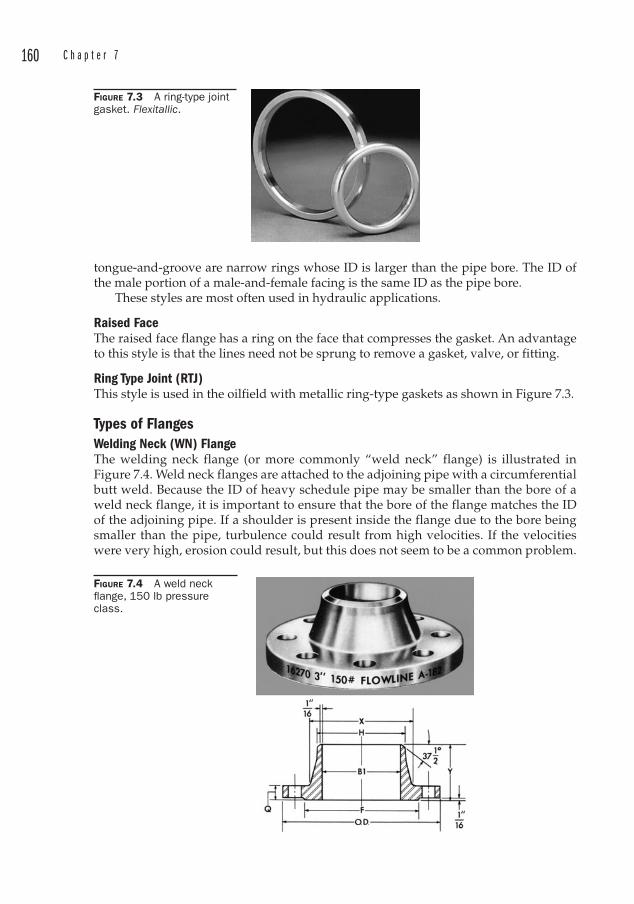
160 C h a p t e r 7
tongue-and-groove are narrow rings whose ID is larger than the pipe bore. The ID of the male portion of a male-and-female facing is the same ID as the pipe bore.
These styles are most often used in hydraulic applications.
Raised FaceThe raised face flange has a ring on the face that compresses the gasket. An advantage to this style is that the lines need not be sprung to remove a gasket, valve, or fitting.
Ring Type Joint (RTJ)This style is used in the oilfield with metallic ring-type gaskets as shown in Figure 7.3.
Types of FlangesWelding Neck (WN) FlangeThe welding neck flange (or more commonly “weld neck” flange) is illustrated in Figure 7.4. Weld neck flanges are attached to the adjoining pipe with a circumferential butt weld. Because the ID of heavy schedule pipe may be smaller than the bore of a weld neck flange, it is important to ensure that the bore of the flange matches the ID of the adjoining pipe. If a shoulder is present inside the flange due to the bore being smaller than the pipe, turbulence could result from high velocities. If the velocities were very high, erosion could result, but this does not seem to be a common problem.
FIGURE 7.3 A ring-type joint gasket. Flexitallic.
FIGURE 7.4 A weld neck fl ange, 150 lb pressure class.
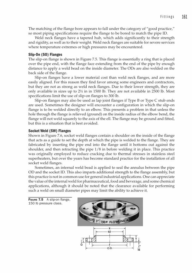
F i t t i n g s 161
The matching of the flange bore appears to fall under the category of “good practice,” so most piping specifications require the flange to be bored to match the pipe ID.
Weld neck flanges have a tapered hub, which adds significantly to their strength and rigidity, as well as to their weight. Weld neck flanges are suitable for severe services where temperature extremes or high pressures may be encountered.
Slip-On (SO) FlangesThe slip-on flange is shown in Figure 7.5. This flange is essentially a ring that is placed over the pipe end, with the flange face extending from the end of the pipe by enough distance to apply a weld bead on the inside diameter. The ODs are also welded on the back side of the flange.
Slip-on flanges have a lower material cost than weld neck flanges, and are more easily aligned. For this reason they find favor among some engineers and contractors, but they are not as strong as weld neck flanges. Due to their lower strength, they are only available in sizes up to 2½ in in 1500 lb. They are not available in 2500 lb. Most specifications limit the use of slip-on flanges to 300 lb.
Slip-on flanges may also be used as lap joint flanges if Type B or Type C stub ends are used. Sometimes the designer will encounter a configuration in which the slip-on flange is to be welded directly to an elbow. This presents a problem in that unless the hole through the flange is relieved (ground) on the inside radius of the elbow bend, the flange will not weld squarely to the axis of the ell. The flange may be ground and fitted, but this is a situation that is best avoided.
Socket Weld (SW) FlangesShown in Figure 7.6, socket weld flanges contain a shoulder on the inside of the flange that acts as a guide to set the depth at which the pipe is welded to the flange. They are fabricated by inserting the pipe end into the flange until it bottoms out against the shoulder, and then retracting the pipe 1/8 in before welding it in place. This practice was originally employed to reduce cracking due to thermal stresses in stainless steel superheaters, but over the years has become standard practice for the installation of all socket weld flanges.
Sometimes, an internal weld bead is applied to seal the annulus between the pipe OD and the socket ID. This also imparts additional strength to the flange assembly, but this practice is not in common use for general industrial applications. One can appreciate the value of the internal weld for pharmaceutical, food and beverage, and some chemical applications, although it should be noted that the clearance available for performing such a weld on small diameter pipes may limit the ability to achieve it.
FIGURE 7.5 A slip-on fl ange, 150 lb pressure class.
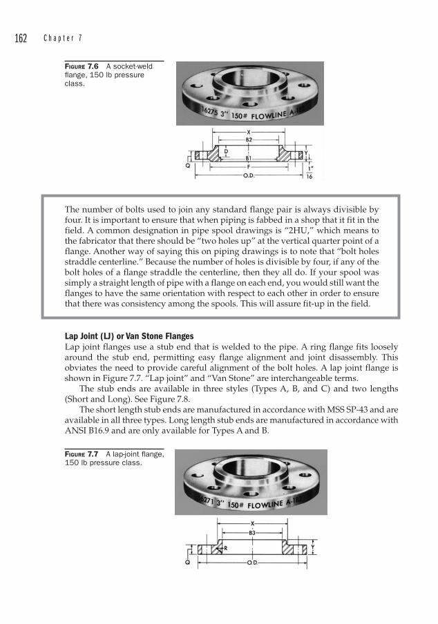
162 C h a p t e r 7
The number of bolts used to join any standard flange pair is always divisible by four. It is important to ensure that when piping is fabbed in a shop that it fit in the field. A common designation in pipe spool drawings is “2HU,” which means to the fabricator that there should be “two holes up” at the vertical quarter point of a flange. Another way of saying this on piping drawings is to note that “bolt holes straddle centerline.” Because the number of holes is divisible by four, if any of the bolt holes of a flange straddle the centerline, then they all do. If your spool was simply a straight length of pipe with a flange on each end, you would still want the flanges to have the same orientation with respect to each other in order to ensure that there was consistency among the spools. This will assure fit-up in the field.
Lap Joint (LJ) or Van Stone Flanges Lap joint flanges use a stub end that is welded to the pipe. A ring flange fits loosely around the stub end, permitting easy flange alignment and joint disassembly. This obviates the need to provide careful alignment of the bolt holes. A lap joint flange is shown in Figure 7.7. “Lap joint” and “Van Stone” are interchangeable terms.
The stub ends are available in three styles (Types A, B, and C) and two lengths (Short and Long). See Figure 7.8.
The short length stub ends are manufactured in accordance with MSS SP-43 and are available in all three types. Long length stub ends are manufactured in accordance with ANSI B16.9 and are only available for Types A and B.
FIGURE 7.6 A socket-weld fl ange, 150 lb pressure class.
FIGURE 7.7 A lap-joint fl ange, 150 lb pressure class.
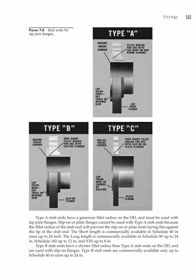
F i t t i n g s 163
FIGURE 7.8 Stub ends for lap joint fl anges.
Type A stub ends have a generous fillet radius on the OD, and must be used with lap joint flanges. Slip-on or plate flanges cannot be used with Type A stub ends because the fillet radius of the stub end will prevent the slip-on or plate from laying flat against the lip of the stub end. The Short length is commercially available in Schedule 40 in sizes up to 24 inch. The Long length is commercially available in Schedule 80 up to 24 in, Schedule 160 up to 12 in, and XXS up to 8 in.
Type B stub ends have a shorter fillet radius than Type A stub ends on the OD, and are used with slip-on flanges. Type B stub ends are commercially available only up to Schedule 40 in sizes up to 24 in.
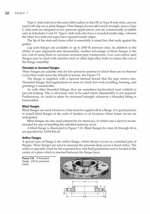
164 C h a p t e r 7
Type C stub ends have the same fillet radius on the OD as Type B stub ends, and are used with slip-on or plate flanges. Plate flanges do not offer much strength, and so Type C stub ends are relegated to low pressure applications, and are commercially available only in Schedules 5 and 10. Type C stub ends also have a rounded inside edge, whereas the other two stub end types have squared inside edges.
The lip of the stub end forms what is essentially a raised face that seals against the gasket.
Lap joint flanges are available in up to 2500 lb pressure class. In addition to the ability to ease alignment and disassembly, another advantage of these flanges is the low cost of using them in corrosion resistant pipe construction. Low-cost carbon steel flanges may be used with stainless steel or other high alloy hubs to reduce the cost of the flange assembly.
Threaded or Screwed Flanges These flanges are suitable only for low-pressure systems in which there are no thermal cycles that could cause the threads to loosen. See Figure 7.9.
The flange is supplied with a tapered internal thread that the pipe screws into. Threaded flanges find applications in areas in which hot work (welding, burning, and grinding) is undesirable.
As with other threaded fittings, they are sometimes backwelded (seal welded ) to prevent leaking. This is obviously only to be used where disassembly is not required. Furthermore, no credit is taken for increased strength whenever a threaded fitting is backwelded.
Blind FlangesBlind flanges are used whenever a line must be capped off at a flange. It is good practice to install blind flanges at the ends of headers or at locations where future tie-ins are anticipated.
Blind flanges are also used extensively for manways, in which case a davit is rec om-mended for ease in handling the unbolted manway cover.
A blind flange is illustrated in Figure 7.10. Blind flanges for sizes 26 through 48 in are specified by ANSI B16.47.
Orifice Flanges A special type of flange is the orifice flange, which always occurs as a matched pair of flanges. These flanges are used to measure the pressure drop across a fixed orifice. The orifice is specially sized for the expected flow and fluid parameters and is located at the center of a plate which is inserted between the flange faces.
FIGURE 7.9 A threaded fl ange, 150 lb pressure class.
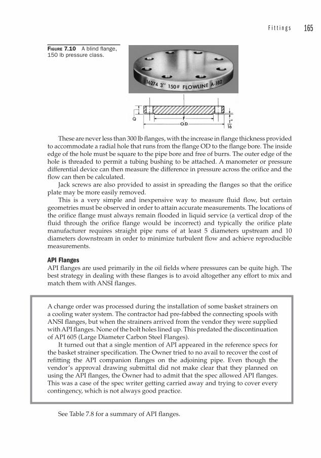
F i t t i n g s 165
These are never less than 300 lb flanges, with the increase in flange thickness provided to accommodate a radial hole that runs from the flange OD to the flange bore. The inside edge of the hole must be square to the pipe bore and free of burrs. The outer edge of the hole is threaded to permit a tubing bushing to be attached. A manometer or pressure differential device can then measure the difference in pressure across the orifice and the flow can then be calculated.
Jack screws are also provided to assist in spreading the flanges so that the orifice plate may be more easily removed.
This is a very simple and inexpensive way to measure fluid flow, but certain geometries must be observed in order to attain accurate measurements. The locations of the orifice flange must always remain flooded in liquid service (a vertical drop of the fluid through the orifice flange would be incorrect) and typically the orifice plate manufacturer requires straight pipe runs of at least 5 diameters upstream and 10 diameters downstream in order to minimize turbulent flow and achieve reproducible measurements.
API FlangesAPI flanges are used primarily in the oil fields where pressures can be quite high. The best strategy in dealing with these flanges is to avoid altogether any effort to mix and match them with ANSI flanges .
FIGURE 7.10 A blind fl ange, 150 lb pressure class.
A change order was processed during the installation of some basket strainers on a cooling water system. The contractor had pre-fabbed the connecting spools with ANSI flanges , but when the strainers arrived from the vendor they were supplied with API flanges . None of the bolt holes lined up. This predated the discontinuation of API 605 (Large Diameter Carbon Steel Flanges).
It turned out that a single mention of API appeared in the reference specs for the basket strainer specification. The Owner tried to no avail to recover the cost of refitting the API companion flanges on the adjoining pipe. Even though the vendor’s approval drawing submittal did not make clear that they planned on using the API flanges , the Owner had to admit that the spec allowed API flanges. This was a case of the spec writer getting carried away and trying to cover every contingency, which is not always good practice.
See Table 7.8 for a summary of API flanges .
166 C h a p t e r 7
Studding Outlets These are essentially metal blocks contoured to fit onto tank and vessel shells, heads and bottoms. The contoured side is welded to the vessel and the other end is provided with a flange facing and holes tapped for the flange bolts.
SAE Flanges SAE 4-bolt flanges are often used on high pressure services like hydraulics or high pressure water systems. SAE Code 61 is for pressure ratings between 500 and 5000 psi in sizes from ½ to 5 in diameter. SAE Code 62 are rated for 6000 psi for all sizes (½ to 2 in).
Both styles of flanges are available in “captive” or “split” styles. The captive flange fits over the hydraulic tube and the split flange is in two parts that clamp the tube on either side. It is important to note that Code 61 and Code 62 are dimensionally similar (see Table 7.9), and so great care must be exercised to prevent using a flange rated for a lower pressure on a high-pressure application. Adding further to the confusion is the fact that at least one manufacturer of hydraulic equipment has developed its own standard for four bolt flanges that is also dimensionally similar to Code 61 and Code 62.
Dielectric Connections Stray electrical currents can accelerate corrosion, so it is desirable to electrically isolate underground piping using dielectric connections at the flanges. See Figure 7.11. A dielectric sleeve covers the bolts, and dielectric washers electrically insulate the nuts from the flange surfaces. The gasket separates the flange faces eliminating metal-to-metal contact between the flanges. Thus isolated, the underground portion of the pipe is usually coated and wrapped to further shield it from contact with earth. The next step in protection is to provide a sacrificial anode that is bonded to the pipe electrically. The anode corrodes instead of the pipe. This is called “cathodic protection. ” Zinc is commonly used as the sacrificial anode, with the pipe acting as the cathode.
Gaskets Full face gaskets (Figure 7.1) extend to the outer diameter of the flange hub. In addition to the hole for the pipe bore, the bolt holes are also cut into the gasket. These are used
API Spec Type Gasketing Pressures Face605 Discontinued6A 6B Weld Neck or
SegmentedR (Oval or Octagonal)
Up to 10,000 psi May or may not have raised faceRX (Oval or
Octagonal)Interchangeablewith R gaskets
Up to 15,000 psi
6BX Weld Neck or Segmented
BX (Octagonal) Up to 20,000 psi Always have raised face
17D SS Weld Neck or Blind Flange
BX Up to 10,000 psi May or may not have raised face
SV Swivel (similar to Lap Joint)
BX Up to 10,000 psi May or may not have raised face
TABLE 7.8 API Flanges.
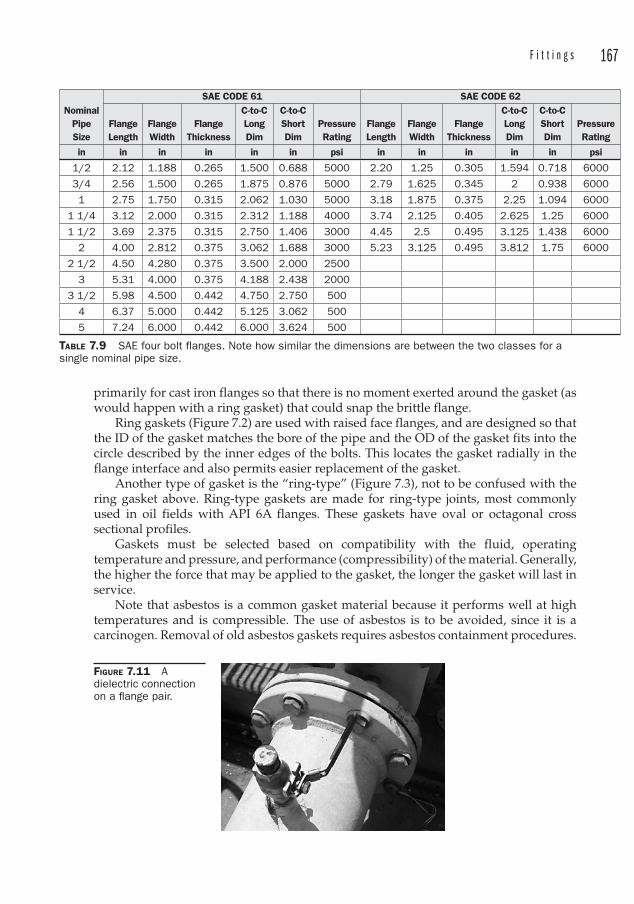
F i t t i n g s 167
primarily for cast iron flanges so that there is no moment exerted around the gasket (as would happen with a ring gasket) that could snap the brittle flange.
Ring gaskets (Figure 7.2) are used with raised face flanges, and are designed so that the ID of the gasket matches the bore of the pipe and the OD of the gasket fits into the circle described by the inner edges of the bolts. This locates the gasket radially in the flange interface and also permits easier replacement of the gasket.
Another type of gasket is the “ring-type” (Figure 7.3), not to be confused with the ring gasket above. Ring-type gaskets are made for ring-type joints, most commonly used in oil fields with API 6A flanges. These gaskets have oval or octagonal cross sectional profiles.
Gaskets must be selected based on compatibility with the fluid, operating temperature and pressure, and performance (compressibility) of the material. Generally, the higher the force that may be applied to the gasket, the longer the gasket will last in service.
Note that asbestos is a common gasket material because it performs well at high temperatures and is compressible. The use of asbestos is to be avoided, since it is a carcinogen. Removal of old asbestos gaskets requires asbestos containment procedures.
Nominal Pipe Size
SAE CODE 61 SAE CODE 62
Flange Length
Flange Width
Flange Thickness
C-to-C Long Dim
C-to-C Short Dim
Pressure Rating
Flange Length
Flange Width
Flange Thickness
C-to-C Long Dim
C-to-C Short Dim
Pressure Rating
in in in in in in psi in in in in in psi
1/2 2.12 1.188 0.265 1.500 0.688 5000 2.20 1.25 0.305 1.594 0.718 6000
3/4 2.56 1.500 0.265 1.875 0.876 5000 2.79 1.625 0.345 2 0.938 6000
1 2.75 1.750 0.315 2.062 1.030 5000 3.18 1.875 0.375 2.25 1.094 6000
1 1/4 3.12 2.000 0.315 2.312 1.188 4000 3.74 2.125 0.405 2.625 1.25 6000
1 1/2 3.69 2.375 0.315 2.750 1.406 3000 4.45 2.5 0.495 3.125 1.438 6000
2 4.00 2.812 0.375 3.062 1.688 3000 5.23 3.125 0.495 3.812 1.75 6000
2 1/2 4.50 4.280 0.375 3.500 2.000 2500
3 5.31 4.000 0.375 4.188 2.438 2000
3 1/2 5.98 4.500 0.442 4.750 2.750 500
4 6.37 5.000 0.442 5.125 3.062 500
5 7.24 6.000 0.442 6.000 3.624 500
TABLE 7.9 SAE four bolt flanges. Note how similar the dimensions are between the two classes for a single nominal pipe size.
FIGURE 7.11 Adielectric connection on a fl ange pair.
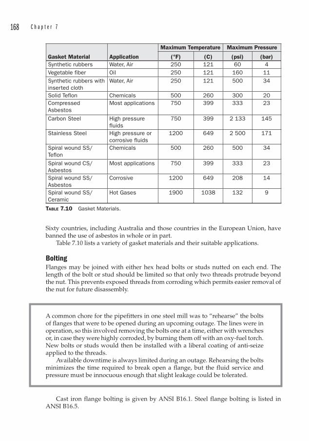
168 C h a p t e r 7
Sixty countries, including Australia and those countries in the European Union, have banned the use of asbestos in whole or in part.
Table 7.10 lists a variety of gasket materials and their suitable applications.
BoltingFlanges may be joined with either hex head bolts or studs nutted on each end. The length of the bolt or stud should be limited so that only two threads protrude beyond the nut. This prevents exposed threads from corroding which permits easier removal of the nut for future disassembly.
A common chore for the pipefitters in one steel mill was to “rehearse” the bolts of flanges that were to be opened during an upcoming outage. The lines were in operation, so this involved removing the bolts one at a time, either with wrenches or, in case they were highly corroded, by burning them off with an oxy-fuel torch. New bolts or studs would then be installed with a liberal coating of anti-seize applied to the threads.
Available downtime is always limited during an outage. Rehearsing the bolts minimizes the time required to break open a flange, but the fluid service and pressure must be innocuous enough that slight leakage could be tolerated.
Gasket Material Application
Maximum Temperature Maximum Pressure
(°F) (C) (psi) (bar)Synthetic rubbers Water, Air 250 121 60 4Vegetable fiber Oil 250 121 160 11Synthetic rubbers with inserted cloth
Water, Air 250 121 500 34
Solid Teflon Chemicals 500 260 300 20CompressedAsbestos
Most applications 750 399 333 23
Carbon Steel High pressure fluids
750 399 2 133 145
Stainless Steel High pressure or corrosive fluids
1200 649 2 500 171
Spiral wound SS/Teflon
Chemicals 500 260 500 34
Spiral wound CS/Asbestos
Most applications 750 399 333 23
Spiral wound SS/Asbestos
Corrosive 1200 649 208 14
Spiral wound SS/Ceramic
Hot Gases 1900 1038 132 9
TABLE 7.10 Gasket Materials.
Cast iron flange bolting is given by ANSI B16.1. Steel flange bolting is listed in ANSI B16.5.
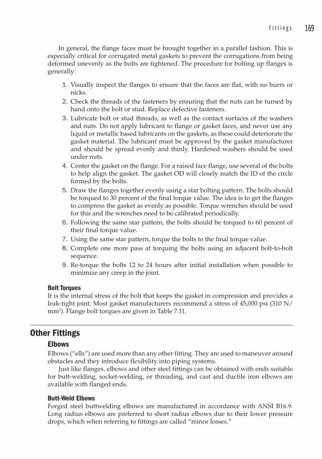
F i t t i n g s 169
In general, the flange faces must be brought together in a parallel fashion. This is especially critical for corrugated metal gaskets to prevent the corrugations from being deformed unevenly as the bolts are tightened. The procedure for bolting up flanges is generally:
1. Visually inspect the flanges to ensure that the faces are flat, with no burrs or nicks.
2. Check the threads of the fasteners by ensuring that the nuts can be turned by hand onto the bolt or stud. Replace defective fasteners.
3. Lubricate bolt or stud threads, as well as the contact surfaces of the washers and nuts. Do not apply lubricant to flange or gasket faces, and never use any liquid or metallic based lubricants on the gaskets, as these could deteriorate the gasket material. The lubricant must be approved by the gasket manufacturer and should be spread evenly and thinly. Hardened washers should be used under nuts.
4. Center the gasket on the flange. For a raised face flange, use several of the bolts to help align the gasket. The gasket OD will closely match the ID of the circle formed by the bolts.
5. Draw the flanges together evenly using a star bolting pattern. The bolts should be torqued to 30 percent of the final torque value. The idea is to get the flanges to compress the gasket as evenly as possible. Torque wrenches should be used for this and the wrenches need to be calibrated periodically.
6. Following the same star pattern, the bolts should be torqued to 60 percent of their final torque value.
7. Using the same star pattern, torque the bolts to the final torque value. 8. Complete one more pass at torquing the bolts using an adjacent bolt-to-bolt
sequence. 9. Re-torque the bolts 12 to 24 hours after initial installation when possible to
minimize any creep in the joint.
Bolt Torques It is the internal stress of the bolt that keeps the gasket in compression and provides a leak-tight joint. Most gasket manufacturers recommend a stress of 45,000 psi (310 N/mm2). Flange bolt torques are given in Table 7.11.
Other FittingsElbowsElbows (“ells”) are used more than any other fitting. They are used to maneuver around obstacles and they introduce flexibility into piping systems.
Just like flanges, elbows and other steel fittings can be obtained with ends suitable for butt-welding, socket-welding, or threading, and cast and ductile iron elbows are available with flanged ends.
Butt-Weld Elbows Forged steel buttwelding elbows are manufactured in accordance with ANSI B16.9. Long radius elbows are preferred to short radius elbows due to their lower pressure drops, which when referring to fittings are called “minor losses.”
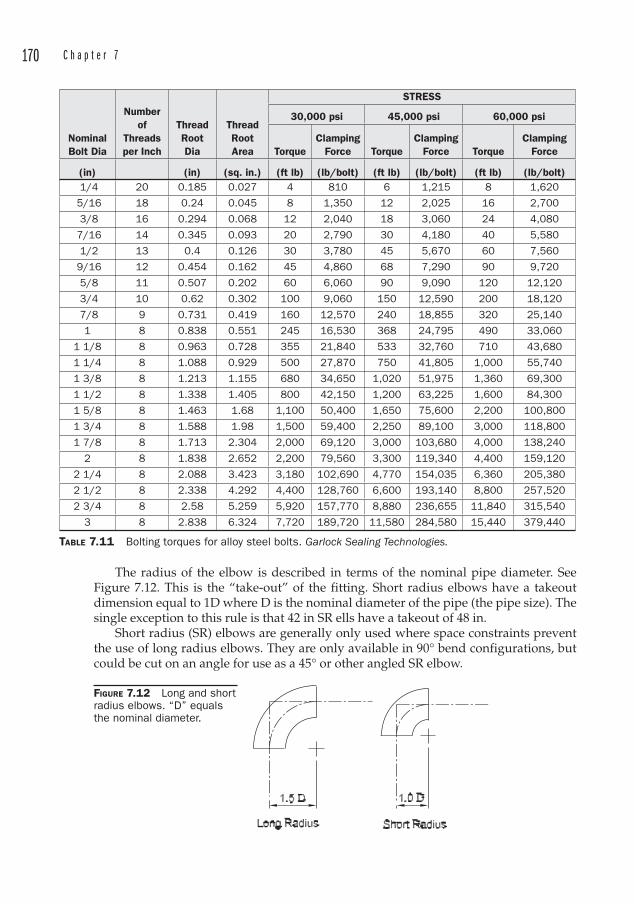
170 C h a p t e r 7
The radius of the elbow is described in terms of the nominal pipe diameter. See Figure 7.12. This is the “take-out ” of the fitting. Short radius elbows have a takeout dimension equal to 1D where D is the nominal diameter of the pipe (the pipe size). The single exception to this rule is that 42 in SR ells have a takeout of 48 in.
Short radius (SR) elbows are generally only used where space constraints prevent the use of long radius elbows. They are only available in 90° bend configurations, but could be cut on an angle for use as a 45° or other angled SR elbow.
NominalBolt Dia
Numberof
Threadsper Inch
ThreadRootDia
ThreadRootArea
STRESS
30,000 psi 45,000 psi 60,000 psi
TorqueClamping
Force TorqueClamping
Force TorqueClamping
Force
(in) (in) (sq. in.) (ft lb) (lb/bolt) (ft lb) (lb/bolt) (ft lb) (lb/bolt) 1/4 20 0.185 0.027 4 810 6 1,215 8 1,620
5/16 18 0.24 0.045 8 1,350 12 2,025 16 2,700
3/8 16 0.294 0.068 12 2,040 18 3,060 24 4,080
7/16 14 0.345 0.093 20 2,790 30 4,180 40 5,580
1/2 13 0.4 0.126 30 3,780 45 5,670 60 7,560
9/16 12 0.454 0.162 45 4,860 68 7,290 90 9,720
5/8 11 0.507 0.202 60 6,060 90 9,090 120 12,120
3/4 10 0.62 0.302 100 9,060 150 12,590 200 18,120
7/8 9 0.731 0.419 160 12,570 240 18,855 320 25,140
1 8 0.838 0.551 245 16,530 368 24,795 490 33,060
1 1/8 8 0.963 0.728 355 21,840 533 32,760 710 43,680
1 1/4 8 1.088 0.929 500 27,870 750 41,805 1,000 55,740
1 3/8 8 1.213 1.155 680 34,650 1,020 51,975 1,360 69,300
1 1/2 8 1.338 1.405 800 42,150 1,200 63,225 1,600 84,300
1 5/8 8 1.463 1.68 1,100 50,400 1,650 75,600 2,200 100,800
1 3/4 8 1.588 1.98 1,500 59,400 2,250 89,100 3,000 118,800
1 7/8 8 1.713 2.304 2,000 69,120 3,000 103,680 4,000 138,240
2 8 1.838 2.652 2,200 79,560 3,300 119,340 4,400 159,120
2 1/4 8 2.088 3.423 3,180 102,690 4,770 154,035 6,360 205,380
2 1/2 8 2.338 4.292 4,400 128,760 6,600 193,140 8,800 257,520
2 3/4 8 2.58 5.259 5,920 157,770 8,880 236,655 11,840 315,540
3 8 2.838 6.324 7,720 189,720 11,580 284,580 15,440 379,440
TABLE 7.11 Bolting torques for alloy steel bolts. Garlock Sealing Technologies.
FIGURE 7.12 Long and short radius elbows. “D” equals the nominal diameter.
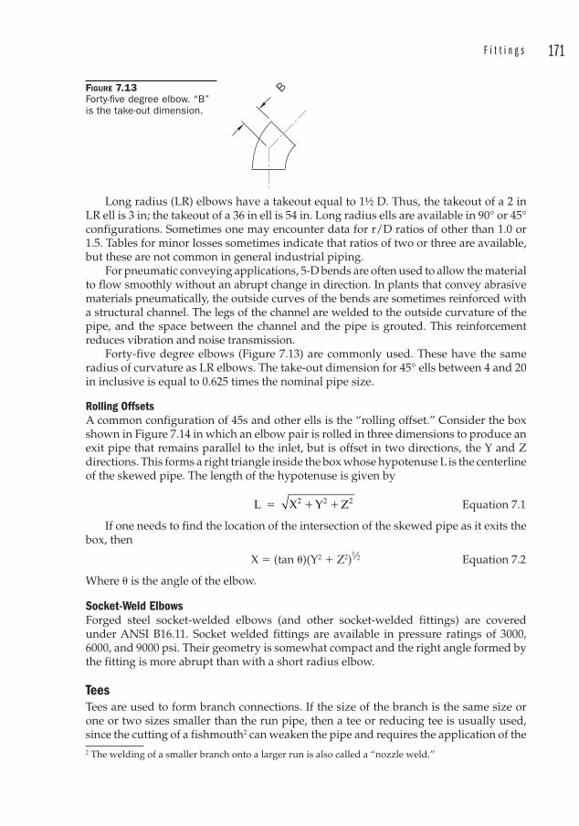
F i t t i n g s 171
Long radius (LR) elbows have a takeout equal to 1½ D. Thus, the takeout of a 2 in LR ell is 3 in; the takeout of a 36 in ell is 54 in. Long radius ells are available in 90° or 45° configurations. Sometimes one may encounter data for r/D ratios of other than 1.0 or 1.5. Tables for minor losses sometimes indicate that ratios of two or three are available, but these are not common in general industrial piping.
For pneumatic conveying applications, 5-D bends are often used to allow the material to flow smoothly without an abrupt change in direction. In plants that convey abrasive materials pneumatically, the outside curves of the bends are sometimes reinforced with a structural channel. The legs of the channel are welded to the outside curvature of the pipe, and the space between the channel and the pipe is grouted. This reinforcement reduces vibration and noise transmission.
Forty-five degree elbows (Figure 7.13) are commonly used. These have the same radius of curvature as LR elbows. The take-out dimension for 45° ells between 4 and 20 in inclusive is equal to 0.625 times the nominal pipe size.
Rolling Offsets A common configuration of 45s and other ells is the “rolling offset.” Consider the box shown in Figure 7.14 in which an elbow pair is rolled in three dimensions to produce an exit pipe that remains parallel to the inlet, but is offset in two directions, the Y and Z directions. This forms a right triangle inside the box whose hypotenuse L is the centerline of the skewed pipe. The length of the hypotenuse is given by
L X Y Z2 2 2� � � Equation 7.1
If one needs to find the location of the intersection of the skewed pipe as it exits the box, then
X � (tan �)(Y2 � Z2)1⁄2 Equation 7.2
Where � is the angle of the elbow.
Socket-Weld Elbows F orged steel socket-welded elbows (and other socket-welded fittings) are covered under ANSI B16.11. Socket welded fittings are available in pressure ratings of 3000, 6000, and 9000 psi. Their geometry is somewhat compact and the right angle formed by the fitting is more abrupt than with a short radius elbow.
TeesTe es ar e used to form branch connections. If the size of the branch is the same size or one or two sizes smaller than the run pipe, then a tee or reducing tee is usually used, since the cutting of a fishmouth2 can weaken the pipe and requires the application of the 2 The welding of a smaller branch onto a larger run is also called a “nozzle weld .”
FIGURE 7.13 Forty-fi ve degree elbow. “B” is the take-out dimension.
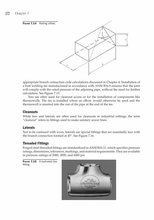
172 C h a p t e r 7
appropriate branch connection code calculations discussed in Chapter 4. Installation of a butt welding tee manufactured in accordance with ANSI B16.9 ensures that the joint will comply with the rated pressure of the adjoining pipe, without the need for further calculation. See Figure 7.15.
Tees ar e often used for cleanout access or for the installation of components like thermowells. The tee is installed where an elbow would otherwise be used and the thermowell is inserted into the run of the pipe at the end of the tee.
CleanoutsWh ile tees and laterals are often used for cleanouts in industrial settings, the term “cleanout” refers to fittings used to snake sanitary sewer lines.
LateralsNo t to be confused with wyes, laterals are special fittings that are essentially tees with the branch connection formed at 45°. See Figure 7.16.
Threaded FittingsForged steel threaded fittings are standardized in ANSI B16.11, which specifies pressure ratings, dimensions, tolerances, markings, and material requirements. They are available in pressure ratings of 2000, 3000, and 6000 psi.
X
�
YL
FIGURE 7.14 Rolling offset.
FIGURE 7.15 A butt-weld tee fi tting.
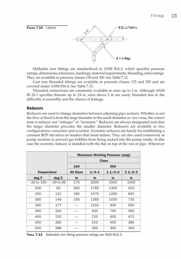
F i t t i n g s 173
Malleable iron fittings ar e standardized in ANSI B16.3, which specifies pressure ratings, dimensions, tolerances, markings, material requirements, threading, and coatings. They are available in pressure classes 150 and 300. See Table 7.12.
Cast iron threaded fittings ar e available in pressure classes 125 and 250 and are covered under ANSI B16.4. See Table 7.13.
Threaded connections are commonly available in sizes up to 2 in. Although ANSI B1.20.1 specifies threads up to 24 in, sizes above 2 in are rarely threaded due to the difficulty in assembly and the chance of leakage.
ReducersRe ducers ar e used to change diameters between adjoining pipe sections. Whether or not the flow of fluid is from the large diameter to the small diameter or vice versa, the correct term is reducer, not “enlarger” or “increaser.” Reducers are always designated such that the larger diameter precedes the smaller diameter. Reducers are available in two configurations: concentric and eccentric. Eccentric reducers are handy for establishing a constant BOP elevation on headers that must reduce. They are also used extensively at pump suctions to prevent gas bubbles from being sucked into the pump intake. In this case the eccentric reducer is installed with the flat on top of the run of pipe. Whenever
FIGURE 7.16 Lateral.
Temperature
Maximum Working Pressure (psig)
Class
150 300
All Sizes 1/4–1 1 1/4–2 2 1/2–3
deg F deg C in in in in–20 to 150 –29 to 66 175 2000 1500 1000
200 93 265 1785 1350 910
250 121 185 1575 1200 825
300 149 150 1360 1050 735
350 177 — 1150 900 650
400 204 — 935 750 560
450 232 — 725 600 475
500 260 — 510 450 385
550 288 — 300 300 300
TABLE 7.12 Malleable iron fitting pressure ratings per ANSI B16.3.
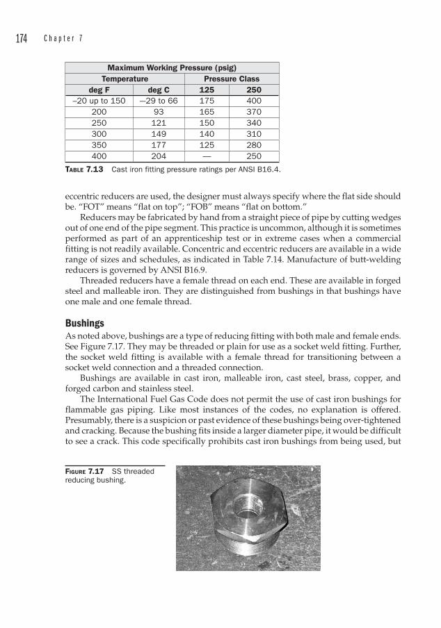
174 C h a p t e r 7
eccentric reducers are used, the designer must always specify where the flat side should be. “FOT” means “flat on top”; “FOB” means “flat on bottom.”
Reducers ma y be fabricated by hand from a straight piece of pipe by cutting wedges out of one end of the pipe segment. This practice is uncommon, although it is sometimes performed as part of an apprenticeship test or in extreme cases when a commercial fitting is not readily available. Concentric and eccentric reducers are available in a wide range of sizes and schedules, as indicated in Table 7.14. Manufacture of butt-welding reducers is governed by ANSI B16.9.
Threaded reducers have a female thread on each end. These are available in forged steel and malleable iron. They are distinguished from bushings in that bushings have one male and one female thread.
BushingsAs noted above, bushings ar e a type of reducing fitting with both male and female ends. See Figure 7.17. They may be threaded or plain for use as a socket weld fitting. Further, the socket weld fitting is available with a female thread for transitioning between a socket weld connection and a threaded connection.
Bushings are available in cast iron, malleable iron, cast steel, brass, copper, and forged carbon and stainless steel.
The International Fuel Gas Code do es not permit the use of cast iron bushings fo r flammable gas piping. Like most instances of the codes, no explanation is offered. Presumably, there is a suspicion or past evidence of these bushings being over-tightened and cracking. Because the bushing fits inside a larger diameter pipe, it would be difficult to see a crack. This code specifically prohibits cast iron bushings from being used, but
Maximum Working Pressure (psig)Temperature Pressure Class
deg F deg C 125 250–20 up to 150 –-29 to 66 175 400
200 93 165 370250 121 150 340300 149 140 310350 177 125 280400 204 — 250
TABLE 7.13 Cast iron fitting pressure ratings per ANSI B16.4.
FIGURE 7.17 SS threaded reducing bushing.
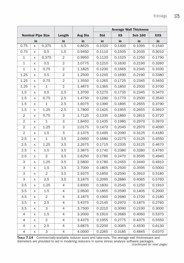
F i t t i n g s 175
Nominal Pipe Size Length Avg Dia
Average Wall Thickness
Std XS Sch 160 XXS
in in in in in in in0.75 x 0.375 1.5 0.8625 0.1020 0.1400 0.1095 0.1540
0.75 x 0.5 1.5 0.9450 0.1110 0.1505 0.2035 0.3010
1 x 0.375 2 0.9950 0.1120 0.1525 0.1250 0.1790
1 x 0.5 2 1.0775 0.1210 0.1630 0.2190 0.3260
1 x 0.75 2 1.1825 0.1230 0.1665 0.2345 0.3330
1.25 x 0.5 2 1.2500 0.1245 0.1690 0.2190 0.3380
1.25 x 0.75 2 1.3550 0.1265 0.1725 0.2345 0.3450
1.25 x 1 2 1.4875 0.1365 0.1850 0.2500 0.3700
1.5 x 0.5 2.5 1.3700 0.1270 0.1735 0.2345 0.3470
1.5 x 0.75 2.5 1.4750 0.1290 0.1770 0.2500 0.3540
1.5 x 1 2.5 1.6075 0.1390 0.1895 0.2655 0.3790
1.5 x 1.25 2.5 1.7800 0.1425 0.1955 0.2655 0.3910
2 x 0.75 3 1.7125 0.1335 0.1860 0.2815 0.3720
2 x 1 3 1.8450 0.1435 0.1985 0.2970 0.3970
2 x 1.25 3 2.0175 0.1470 0.2045 0.2970 0.4090
2 x 1.5 3 2.1375 0.1495 0.2090 0.3125 0.4180
2.5 x 1 3.5 2.0950 0.1680 0.2275 0.3125 0.4550
2.5 x 1.25 3.5 2.2675 0.1715 0.2335 0.3125 0.4670
2.5 x 1.5 3.5 2.3875 0.1740 0.2380 0.3280 0.4760
2.5 x 2 3.5 2.6250 0.1785 0.2470 0.3595 0.4940
3 x 1.25 3.5 2.5800 0.1780 0.2455 0.3440 0.4910
3 x 1.5 3.5 2.7000 0.1805 0.2500 0.3595 0.5000
3 x 2 3.5 2.9375 0.1850 0.2590 0.3910 0.5180
3 x 2.5 3.5 3.1875 0.2095 0.2880 0.4065 0.5760
3.5 x 1.25 4 2.8300 0.1830 0.2545 0.1250 0.1910
3.5 x 1.5 4 2.9500 0.1855 0.2590 0.1405 0.2000
3.5 x 2 4 3.1875 0.1900 0.2680 0.1720 0.2180
3.5 x 2.5 4 3.4375 0.2145 0.2970 0.1875 0.2760
3.5 x 3 4 3.7500 0.2210 0.3090 0.2190 0.3000
4 x 1.5 4 3.2000 0.1910 0.2685 0.4060 0.5370
4 x 2 4 3.4375 0.1955 0.2775 0.4375 0.5550
4 x 2.5 4 3.6875 0.2200 0.3065 0.4530 0.6130
4 x 3 4 4.0000 0.2265 0.3185 0.4845 0.6370
TABLE 7.14 Commercially-available reducer sizes and take-outs. The average wall thicknesses and diameters are provided to aid in modeling reducers in some stress analysis software packages.
(continued on next page)
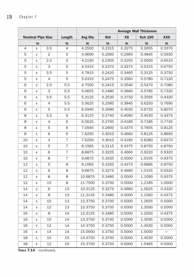
176 C h a p t e r 7
Nominal Pipe Size Length Avg Dia
Average Wall Thickness
Std XS Sch 160 XXS
in in in in in in in4 x 3.5 4 4.2500 0.2315 0.3275 0.2655 0.3370
5 x 2 5 3.9690 0.2060 0.2965 0.4845 0.5930
5 x 2.5 5 4.2190 0.2305 0.3255 0.5000 0.6510
5 x 3 5 4.5315 0.2370 0.3375 0.5315 0.6750
5 x 3.5 5 4.7815 0.2420 0.3465 0.3125 0.3750
5 x 4 5 5.0315 0.2475 0.3560 0.5780 0.7120
6 x 2.5 5.5 4.7500 0.2415 0.3540 0.5470 0.7080
6 x 3 5.5 5.0625 0.2480 0.3660 0.5785 0.7320
6 x 3.5 5.5 5.3125 0.2530 0.3750 0.3595 0.4320
6 x 4 5.5 5.5625 0.2585 0.3845 0.6250 0.7690
6 x 5 5.5 6.0940 0.2690 0.4035 0.6720 0.8070
8 x 3.5 6 6.3125 0.2740 0.4090 0.4530 0.4375
8 x 4 6 6.5625 0.2795 0.4185 0.7185 0.7745
8 x 5 6 7.0940 0.2900 0.4375 0.7655 0.8125
8 x 6 6 7.6250 0.3010 0.4660 0.8125 0.8695
10 x 4 7 7.6250 0.3010 0.4185 0.8280 0.8370
10 x 5 7 8.1565 0.3115 0.4375 0.8750 0.8750
10 x 6 7 8.6875 0.3225 0.4660 0.9220 0.9320
10 x 8 7 9.6875 0.3435 0.5000 1.0155 0.9375
12 x 5 8 9.1565 0.3165 0.4375 0.9685 0.8750
12 x 6 8 9.6875 0.3275 0.4660 1.0155 0.9320
12 x 8 8 10.6875 0.3485 0.5000 1.1090 0.9375
12 x 10 8 11.7500 0.3700 0.5000 1.2185 1.0000
14 x 6 13 10.3125 0.3275 0.4660 1.0625 0.4320
14 x 8 13 11.3125 0.3485 0.5000 1.1560 0.4375
14 x 10 13 12.3750 0.3700 0.5000 1.2655 0.5000
14 x 12 13 13.3750 0.3750 0.5000 1.3590 0.5000
16 x 8 14 12.3125 0.3485 0.5000 1.2500 0.4375
16 x 10 14 13.3750 0.3700 0.5000 1.3595 0.5000
16 x 12 14 14.3750 0.3750 0.5000 1.4530 0.5000
16 x 14 14 15.0000 0.3750 0.5000 1.5000 —
18 x 10 15 14.3750 0.3700 0.5000 1.4530 0.5000
18 x 12 15 15.3750 0.3750 0.5000 1.5465 0.5000
TABLE 7.14 (continued).

F i t t i n g s 177
Nominal Pipe Size Length Avg Dia
Average Wall Thickness
Std XS Sch 160 XXS
in in in in in in in18 x 14 15 16.0000 0.3750 0.5000 1.5935 —
18 x 16 15 17.0000 0.3750 0.5000 1.6875 —
20 x 12 20 16.3750 0.3750 0.5000 1.6405 0.5000
20 x 14 20 17.0000 0.3750 0.5000 1.6875 —
20 x 16 20 18.0000 0.3750 0.5000 1.7815 —
20 x 18 20 19.0000 0.3750 0.5000 1.8750 —
22 x 14 20 18.0000 0.3750 0.5000 1.7655 —
22 x 16 20 19.0000 0.3750 0.5000 1.8595 —
22 x 18 20 20.0000 0.3750 0.5000 1.9530 —
22 x 20 20 21.0000 0.3750 0.5000 2.0470 —
24 x 14 20 19.0000 0.3750 0.5000 1.8750 —
24 x 16 20 20.0000 0.3750 0.5000 1.9690 —
24 x 18 20 21.0000 0.3750 0.5000 2.0625 —
24 x 20 20 22.0000 0.3750 0.5000 2.1565 —
26 x 18 24 22.0000 0.3750 0.5000 0.8905 —
26 x 20 24 23.0000 0.3750 0.5000 0.9845 —
26 x 22 24 24.0000 0.3750 0.5000 1.0625 —
26 x 24 24 25.0000 0.3750 0.5000 1.1720 —
28 x 18 24 23.0000 0.3750 0.5000 0.8905 —
28 x 20 24 24.0000 0.3750 0.5000 0.9845 —
28 x 24 24 26.0000 0.3750 0.5000 1.1720 —
28 x 26 24 27.0000 0.3750 0.5000 — —
30 x 20 24 25.0000 0.3750 0.5000 0.9845 —
30 x 24 24 27.0000 0.3750 0.5000 1.1720 —
30 x 26 24 28.0000 0.3750 0.5000 — —
30 x 28 24 29.0000 0.3750 0.5000 — —
32 x 24 24 28.0000 0.3750 0.5000 1.1720 —
32 x 26 24 29.0000 0.3750 0.5000 — —
32 x 28 24 30.0000 0.3750 0.5000 — —
32 x 30 24 31.0000 0.3750 0.5000 — —
34 x 24 24 29.0000 0.3750 0.5000 1.1720 —
34 x 26 24 30.0000 0.3750 0.5000 — —
34 x 30 24 32.0000 0.3750 0.5000 — —
TABLE 7.14 (continued). (continued on next page)
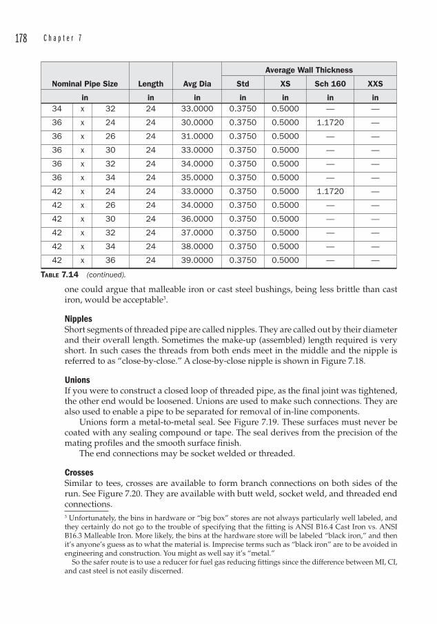
178 C h a p t e r 7
one could argue that malleable iron or cast steel bushings, being less brittle than cast iron, would be acceptable3.
NipplesShort segments of threaded pipe are called nipples. T hey are called out by their diameter and their overall length. Sometimes the make-up (assembled) length required is very short. In such cases the threads from both ends meet in the middle and the nipple is referred to as “close-by-close.” A close-by-close nipple is shown in Figure 7.18.
UnionsIf you were to construct a closed loop of threaded pipe, as the final joint was tightened, the other end would be loosened. Unions ar e used to make such connections. They are also used to enable a pipe to be separated for removal of in-line components.
Unions fo rm a metal-to-metal seal. See Figure 7.19. These surfaces must never be coated with any sealing compound or tape. The seal derives from the precision of the mating profiles and the smooth surface finish.
The end connections may be socket welded or threaded.
CrossesSi milar to tees, crosses are available to form branch connections on both sides of the run. See Figure 7.20. They are available with butt weld, socket weld, and threaded end connections.3 Unfortunately, the bins in hardware or “big box” stores are not always particularly well labeled, and they certainly do not go to the trouble of specifying that the fitting is ANSI B16.4 Cast Iron vs. ANSI B16.3 Malleable Iron. More likely, the bins at the hardware store will be labeled “black iron,” and then it’s anyone’s guess as to what the material is. Imprecise terms such as “black iron” are to be avoided in engineering and construction. You might as well say it’s “metal.” So the safer route is to use a reducer for fuel gas reducing fittings since the difference between MI, CI, and cast steel is not easily discerned.
Nominal Pipe Size Length Avg Dia
Average Wall Thickness
Std XS Sch 160 XXS
in in in in in in in34 x 32 24 33.0000 0.3750 0.5000 — —
36 x 24 24 30.0000 0.3750 0.5000 1.1720 —
36 x 26 24 31.0000 0.3750 0.5000 — —
36 x 30 24 33.0000 0.3750 0.5000 — —
36 x 32 24 34.0000 0.3750 0.5000 — —
36 x 34 24 35.0000 0.3750 0.5000 — —
42 x 24 24 33.0000 0.3750 0.5000 1.1720 —
42 x 26 24 34.0000 0.3750 0.5000 — —
42 x 30 24 36.0000 0.3750 0.5000 — —
42 x 32 24 37.0000 0.3750 0.5000 — —
42 x 34 24 38.0000 0.3750 0.5000 — —
42 x 36 24 39.0000 0.3750 0.5000 — —
TABLE 7.14 (continued).
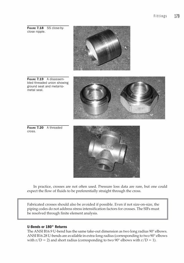
F i t t i n g s 179
In practice, crosses are not often used. Pressure loss data are rare, but one could expect the flow of fluids to be preferentially straight through the cross.
FIGURE 7.18 SS close-by-close nipple.
FIGURE 7.19 A disassem-bled threaded union showing ground seat and metal-to-metal seal.
FIGURE 7.20 A threaded cross.
Fabricated crosses should also be avoided if possible. Even if not size-on-size, the piping codes do not address stress intensification factors fo r crosses. The SIFs must be resolved through finite element analysis.
U-Bends or 180° ReturnsThe ANSI B16.9 U-bend has the same take-out di mension as two long radius 90° elbows. ANSI B16.28 U-bends are available in extra-long radius (corresponding to two 90° elbows with r/D � 2) and short radius (corresponding to two 90° elbows with r/D � 1).
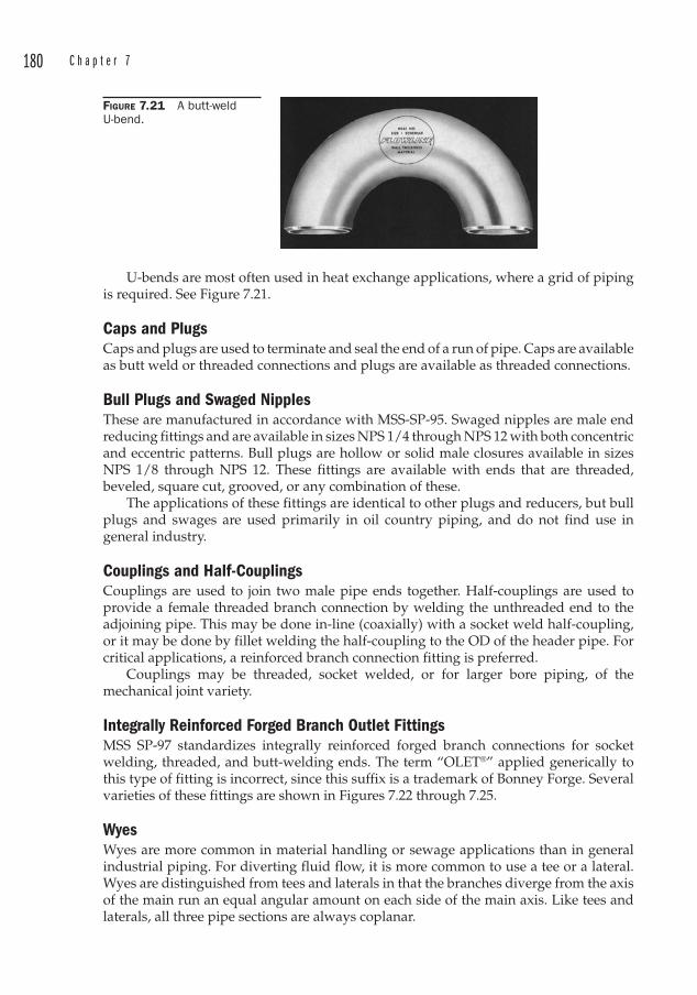
180 C h a p t e r 7
U-bends are most often used in heat exchange applications, where a grid of piping is required. See Figure 7.21.
Caps an d Plugs C aps an d plugs are used to terminate and seal the end of a run of pipe. Caps are available as butt weld or threaded connections and plugs are available as threaded connections.
Bull Plugs an d Swaged NipplesTh ese are manufactured in accordance with MSS-SP-95. Swaged nipples ar e male end reducing fittings and are available in sizes NPS 1/4 through NPS 12 with both concentric and eccentric patterns. Bull plugs ar e hollow or solid male closures available in sizes NPS 1/8 through NPS 12. These fittings are available with ends that are threaded, beveled, square cut, grooved, or any combination of these.
The applications of these fittings are identical to other plugs and reducers, but bull plugs and swages are used primarily in oil country piping, and do not find use in general industry.
Couplings an d Half-CouplingsCouplings ar e used to join two male pipe ends together. Half-couplings are used to provide a female threaded branch connection by welding the unthreaded end to the adjoining pipe. This may be done in-line (coaxially) with a socket weld half-coupling, or it may be done by fillet welding the half-coupling to the OD of the header pipe. For critical applications, a reinforced branch connection fitting is preferred.
Couplings ma y be threaded, socket welded, or for larger bore piping, of the mechanical joint variety.
Integrally Reinforced Forged Branch Outlet FittingsMSS SP-97 standardizes integrally reinforced forged branch connections for socket welding, threaded, and butt-welding ends. The term “OLET®” a pplied generically to this type of fitting is incorrect, since this suffix is a trademark of Bonney Forge. Several varieties of these fittings are shown in Figures 7.22 through 7.25.
WyesWy es ar e more common in material handling or sewage applications than in general industrial piping. For diverting fluid flow, it is more common to use a tee or a lateral. Wyes are distinguished from tees and laterals in that the branches diverge from the axis of the main run an equal angular amount on each side of the main axis. Like tees and laterals, all three pipe sections are always coplanar.
FIGURE 7.21 A butt-weld U-bend.
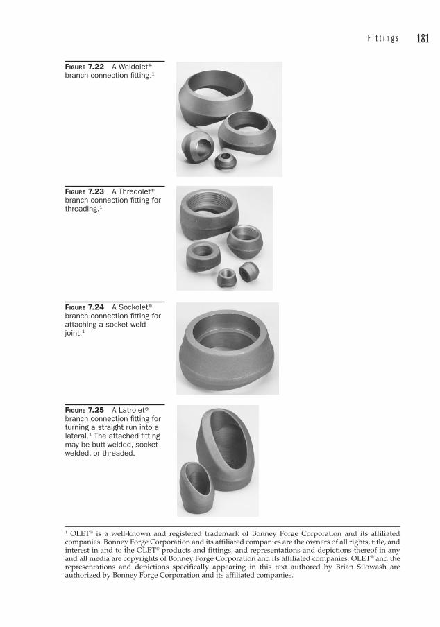
F i t t i n g s 181
FIGURE 7.22 A Weldolet®branch connection fi tting.1
FIGURE 7.23 A Thredolet® branch connection fi tting for threading.1
FIGURE 7.24 A Sockolet®branch connection fi tting for attaching a socket weld joint.1
FIGURE 7.25 A Latrolet® branch connection fi tting for turning a straight run into a lateral.1 The attached fi tting may be butt-welded, socket welded, or threaded.
1 OLET® is a well-known and registered trademark of Bonney Forge Corporation and its affiliated companies. Bonney Forge Corporation and its affiliated companies are the owners of all rights, title, and interest in and to the OLET® products and fittings, and representations and depictions thereof in any and all media are copyrights of Bonney Forge Corporation and its affiliated companies. OLET® and the representations and depictions specifically appearing in this text authored by Brian Silowash are authorized by Bonney Forge Corporation and its affiliated companies.
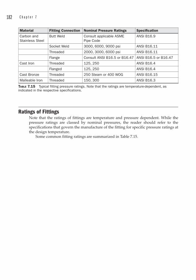
182 C h a p t e r 7
Ratings of FittingsNote that the ratings of fittings are temperature and pressure dependent. While the pressure ratings are classed by nominal pressures, the reader should refer to the specifications that govern the manufacture of the fitting for specific pressure ratings at the design temperature.
Some common fitting ratings are summarized in Table 7.15.
Material Fitting Connection Nominal Pressure Ratings Specification
Carbon and Stainless Steel
Butt Weld Consult applicable ASME Pipe Code
ANSI B16.9
Socket Weld 3000, 6000, 9000 psi ANSI B16.11
Threaded 2000, 3000, 6000 psi ANSI B16.11
Flange Consult ANSI B16.5 or B16.47 ANSI B16.5 or B16.47
Cast Iron Threaded 125, 250 ANSI B16.4
Flanged 125, 250 ANSI B16.4
Cast Bronze Threaded 250 Steam or 400 WOG ANSI B16.15
Malleable Iron Threaded 150, 300 ANSI B16.3
TABLE 7.15 Typical fitting pressure ratings. Note that the ratings are temperature-dependent, as indicated in the respective specifications.
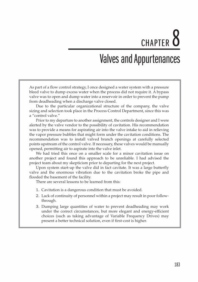
183
CHAPTER 8Valves and Appurtenances
As part of a flow control strategy, I once designed a water system with a pressure bleed valve to dump excess water when the process did not require it. A bypass valve was to open and dump water into a reservoir in order to prevent the pump from deadheading when a discharge valve closed.
Due to the particular organizational structure of the company, the valve sizing and selection took place in the Process Control Department, since this was a “control valve. ”
Prior to my departure to another assignment, the controls designer and I were alerted by the valve vendor to the possibility of cavitation . His recommendation was to provide a means for aspirating air into the valve intake to aid in relieving the vapor pressure bubbles that might form under the cavitation conditions. The recommendation was to install valved branch openings at carefully selected points upstream of the control valve . If necessary, these valves would be manually opened, permitting air to aspirate into the valve inlet.
We had tried this once on a smaller scale for a minor cavitation issue on another project and found this approach to be unreliable. I had advised the project team about my skepticism prior to departing for the next project.
Upon system start-up the valve did in fact cavitate. It was a large butterfly valve and the enormous vibration due to the cavitation broke the pipe and flooded the basement of the facility.
There are several lessons to be learned from this:
1. Cavitation is a dangerous condition that must be avoided.
2. Lack of continuity of personnel within a project may result in poor follow-through.
3. Dumping large quantities of water to prevent deadheading may work under the correct circumstances, but more elegant and energy-efficient choices (such as taking advantage of Variable Frequency Drives ) may present a better technical solution, even if first-cost is higher.
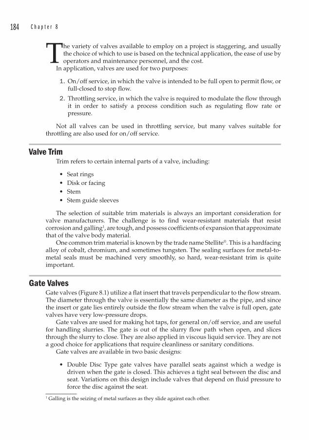
184 C h a p t e r 8
The variety of valves available to employ on a project is staggering, and usually the choice of which to use is based on the technical application, the ease of use by operators and maintenance personnel, and the cost.
In application, valves are used for two purposes:
1. On/off service, in which the valve is intended to be full open to permit flow, or full-closed to stop flow.
2. Throttling service, in which the valve is required to modulate the flow through it in order to satisfy a process condition such as regulating flow rate or pressure.
Not all valves can be used in throttling service, but many valves suitable for throttling are also used for on/off service.
Valve Trim Trim refers to certain internal parts of a valve, including:
• Seat rings• Disk or facing• Stem• Stem guide sleeves
The selection of suitable trim materials is always an important consideration for valve manufacturers. The challenge is to find wear-resistant materials that resist corrosion and galling1, are tough, and possess coefficients of expansion that approximate that of the valve body material.
One common trim material is known by the trade name Stellite® . This is a hardfacing alloy of cobalt, chromium, and sometimes tungsten. The sealing surfaces for metal-to-metal seals must be machined very smoothly, so hard, wear-resistant trim is quite important.
Gate Valves Gate valves (Figure 8.1) utilize a flat insert that travels perpendicular to the flow stream. The diameter through the valve is essentially the same diameter as the pipe, and since the insert or gate lies entirely outside the flow stream when the valve is full open, gate valves have very low-pressure drops.
Gate valves are used for making hot taps, for general on/off service, and are useful for handling slurries. The gate is out of the slurry flow path when open, and slices through the slurry to close. They are also applied in viscous liquid service. They are not a good choice for applications that require cleanliness or sanitary conditions.
Gate valves are available in two basic designs:
• Double Disc Type gate valves have parallel seats against which a wedge is driven when the gate is closed. This achieves a tight seal between the disc and seat. Variations on this design include valves that depend on fluid pressure to force the disc against the seat.
1 Galling is the seizing of metal surfaces as they slide against each other.
V a l v e s a n d A p p u r t e n a n c e s 185
• Wedge Type gate valves have a disc that is in the shape of a wedge that seats against two inclined seats. Solid wedges are most often used and excel in high flow or turbulent applications like steam service, since the solid design minimizes vibration and chatter. Split wedge discs are more flexible and may be used where pipeline strains may distort the valve seats. But pipeline stresses are difficult to predict without a stress analysis, and the operating stresses may be increased by improper installation.
There are two types of gate valve stems; Rising Stem and Non-Rising Stem. Rising Stem valves are preferred because the position of the gate is readily discernible by observing the position of the valve stem. If the stem is up, the gate is open. If the stem is down, then the valve is closed. Figure 8.2 shows an open gate valve in industrial water service. Figure 8.3 shows a closed rising stem gate valve.
Non-Rising Stems are generally only used where a space conflict may arise when the stem is extended. Where Non-Rising Stem valves are used, it may be advisable to post a sign to alert plant personnel to not rely only on looking at the stem to determine the valve position. The Rising Stem design keeps the stem threads out of contact with the fluid. With a Non-Rising Stem design, the threads remain internal to the valve
FIGURE 8.1 Outside Stem & Yoke fl anged gate valve with rising stem and epoxy coated cast iron body. Photoprovided by Watts Regulator Company.
FIGURE 8.2 A rising stem gate valve in the open position. Note the full face gasket on the near fl ange pair.

186 C h a p t e r 8
body and may corrode, erode, or accumulate deposits on the stem threads, rendering operation difficult.
Gate valves are equipped with an outside stem and yoke, giving rise to the term “OS&Y Gate Valve.” At the top of the yoke, a stationary yoke nut advances the lead screw when the handwheel is turned. This raises or lowers the gate.2
Naturally there must be a means to prevent the fluid inside the valve from leaking around the stem as it passes through the valve body. This is accomplished in gate valves through the use of packing that is compacted around the stem with the use of a packing gland. As the packing wears and the valve leaks around the stem, the gland can be tightened progressively to increase the pressure on the packing, deforming it against the sealing surfaces.
Gate valves are only used in on/off applications and should never be applied in situations where the flow of fluid is to be modulated. The reason for this is that a gate valve that is partially open behaves more or less as though it is fully open. There is no control range to speak of. Another reason is that the gate and seats can erode if exposed for extended periods to the flow of fluid, as it is when in the partially open position. Once erosion has occurred a positive seal can never be achieved.
Gate valves may be used for liquids or gases.
Globe ValvesGlobe valves (Figure 8.4) have a rounded body through which the fluid traverses a circuitous path. This results in more pressure drop through a fully open globe valve than a similarly sized gate or ball valve.
Globe valves may be used for on/off or throttling applications of liquids or gases. These valves are constructed with a disk that translates against a seat. The flow of fluid is usually directed up through the seat and around the disk. For this reason, most large globe valves have a direction arrow embossed on the body casting, as shown in Figure 8.5. Sometimes, however, an engineer will desire to install the valve backward. If the screw that attaches the disk to the stem were to fail, they reason that in some circumstances it would be desirable for the disk to fall against the seat, thus stopping the flow. In this case, the valve would fail closed. This configuration also uses system
2 “Righty-tighty/lefty-loosey” applies, but handwheels are often cast with “Open” arrows pointing counterclockwise so that we don’t get confused, especially when they are mounted in positions other than upright.
FIGURE 8.3 A 1 in gate valve used as a steam-out connection.
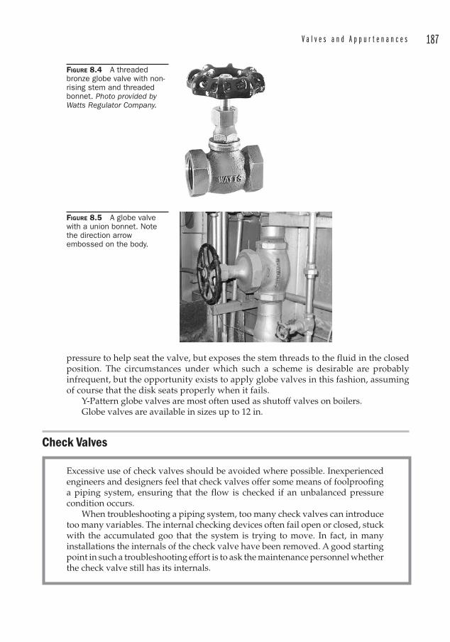
V a l v e s a n d A p p u r t e n a n c e s 187
pressure to help seat the valve, but exposes the stem threads to the fluid in the closed position. The circumstances under which such a scheme is desirable are probably infrequent, but the opportunity exists to apply globe valves in this fashion, assuming of course that the disk seats properly when it fails.
Y-Pattern globe valves are most often used as shutoff valves on boilers.Globe valves are available in sizes up to 12 in.
Check Valves
FIGURE 8.4 A threaded bronze globe valve with non-rising stem and threaded bonnet. Photo provided by Watts Regulator Company.
FIGURE 8.5 A globe valve with a union bonnet. Note the direction arrow embossed on the body.
Excessive use of check valves should be avoided where possible. Inexperienced engineers and designers feel that check valves offer some means of foolproofing a piping system, ensuring that the flow is checked if an unbalanced pressure condition occurs.
When troubleshooting a piping system, too many check valves can introduce too many variables. The internal checking devices often fail open or closed, stuck with the accumulated goo that the system is trying to move. In fact, in many installations the internals of the check valve have been removed. A good starting point in such a troubleshooting effort is to ask the maintenance personnel whether the check valve still has its internals.
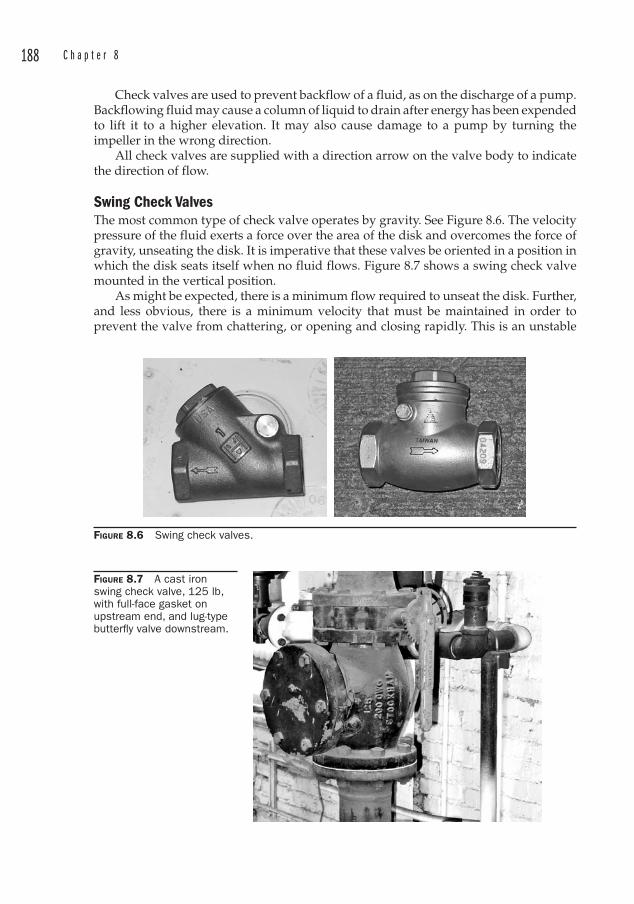
188 C h a p t e r 8
Check valves are used to prevent backflow of a fluid, as on the discharge of a pump. Backflowing fluid may cause a column of liquid to drain after energy has been expended to lift it to a higher elevation. It may also cause damage to a pump by turning the impeller in the wrong direction.
All check valves are supplied with a direction arrow on the valve body to indicate the direction of flow.
Swing Check Valves The most common type of check valve operates by gravity. See Figure 8.6. The velocity pressure of the fluid exerts a force over the area of the disk and overcomes the force of gravity, unseating the disk. It is imperative that these valves be oriented in a position in which the disk seats itself when no fluid flows. Figure 8.7 shows a swing check valve mounted in the vertical position.
As might be expected, there is a minimum flow required to unseat the disk. Further, and less obvious, there is a minimum velocity that must be maintained in order to prevent the valve from chattering, or opening and closing rapidly. This is an unstable
FIGURE 8.6 Swing check valves.
FIGURE 8.7 A cast iron swing check valve, 125 lb, with full-face gasket on upstream end, and lug-type butterfl y valve downstream.

V a l v e s a n d A p p u r t e n a n c e s 189
condition that at best will result in noise, and may lead to valve component failure. Therefore, the valve must sometimes be downsized in order to keep the velocity high enough to keep the disk lifted. For steam, the recommended velocity is 14,000 to 15,000 FPM (71 to 76 m/sec).
The conventional swing check valve pivots on a pin attached to the top of the disk, rotating the disk up and toward the edge of the flow stream when pressure is applied in the intended flow direction by the velocity of the fluid. Should the flow direction happen to be reversed due to a pressure imbalance, the disk swings back down against the valve seat, sealing the valve closed.
Some manufacturers offer a disk whose pin is located closer to the center of the disk. This balances the disk and is alleged to provide better flow characteristics and non-slam closing.
Lift Check Valves Lift check valves are available in straight-through, tee, or wye patterns. This type of check valve may be installed horizontally or vertically, but those lift checks relying solely on gravity must be installed so that the disc travel is vertical. Other valves contain a spring which must be forced open under normal flow conditions. See Figure 8.8.
Ball Check ValvesAnother type of check valve operates using gravity as the checking means. A lightweight polymer ball is captured within the valve body, and at rest lays against a spherical profile seat. These valves must be oriented vertically. They are often used in air-operated diaphragm pumps to prevent the fluid from backflowing into the pump.
Silent Check ValvesThe silent check valve (Figure 8.9) is a spring-loaded straight-through design. These may be constructed with a solid disk that lifts off the seat against inlet pressure or with a twin disc design that is hinged in the center of the disc.
FIGURE 8.8 A lift check valve.
FIGURE 8.9 A cast iron silent check valve used to prevent water hammer due to pump shut down. Photoprovided by Watts regulator Company.
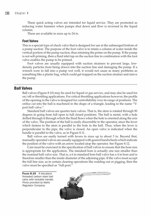
190 C h a p t e r 8
These quick acting valves are intended for liquid service. They are promoted as reducing water hammer when pumps shut down and flow is reversed in the liquid column.
These are available in sizes up to 24 in.
Foot Valves This is a special type of check valve that is designed for use at the submerged bottom of a pump suction. The purpose of the foot valve is to retain a column of water inside the vertical portion of the pump suction, thus retaining the prime on the pump. If the pump is not self-priming, then a fluid inlet tap on the suction line in combination with the foot valve enables the pump to be primed.
Foot valves are usually equipped with suction strainers to prevent large, low-density particles from being drawn into the suction line and damaging the pump. If a wrench were to fall into a pump wet well, it would not cause as many problems as something like a plastic bag, which could get trapped on the suction strainer and starve the pump.
Ball Valves Ball valves (Figure 8.10) may be used for liquid or gas service, and may also be used for on/off or throttling applications. For critical throttling applications however, the profile of the opening in the valve is designed for controllability over its range of positions. The orifice cut into the ball is machined in the shape of a triangle, leading to the name “V-port ball valve. ”
Standard ball valves are quarter-turn valves. That is, the stem is rotated through 90 degrees in going from full open to full closed positions. The ball is metal, with a hole drilled through it through which the fluid flows when the hole is oriented along the axis of the valve. The position of the ball is easily discernible to the operator, since the lever which fastens to the stem is parallel to the hole in the ball. Thus, when the lever is perpendicular to the pipe, the valve is closed. An open valve is indicated when the handle is parallel to the valve, as in Figure 8.11.
Ball valves are easily turned with levers in sizes up to about 3 in. Beyond that, manually operated valves are usually equipped with geared handwheels which indicate the position of the valve with an arrow located atop the operator. See Figure 8.12.
Care must be exercised in the specification of ball valves to ensure that the bore size is appropriate for the application. The standard bore is actually one size smaller than the nominal ball valve size. That is, a 6 in standard bore ball valve has a 4 in bore and is therefore smaller than the inside diameter of the adjoining pipe. If the valve must accept the full line size, as in certain cleaning operations like rodding out or pigging, then the valve must be specified as “full-port.”
FIGURE 8.10 A two-piece threaded carbon steel ball valve with lockable handle.Photo provided by Watts Regulator Company.
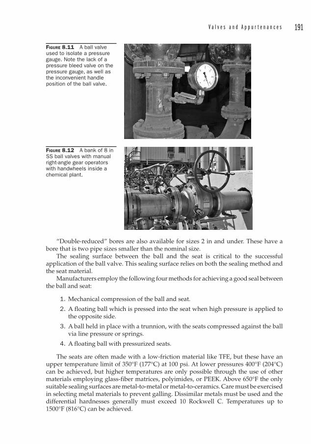
V a l v e s a n d A p p u r t e n a n c e s 191
“Double-reduced” bores are also available for sizes 2 in and under. These have a bore that is two pipe sizes smaller than the nominal size.
The sealing surface between the ball and the seat is critical to the successful application of the ball valve. This sealing surface relies on both the sealing method and the seat material.
Manufacturers employ the following four methods for achieving a good seal between the ball and seat:
1. Mechanical compression of the ball and seat.
2. A floating ball which is pressed into the seat when high pressure is applied to the opposite side.
3. A ball held in place with a trunnion, with the seats compressed against the ball via line pressure or springs.
4. A floating ball with pressurized seats.
The seats are often made with a low-friction material like TFE, but these have an upper temperature limit of 350°F (177°C) at 100 psi. At lower pressures 400°F (204°C) can be achieved, but higher temperatures are only possible through the use of other materials employing glass-fiber matrices, polyimides, or PEEK. Above 650°F the only suitable sealing surfaces are metal-to-metal or metal-to-ceramics. Care must be exercised in selecting metal materials to prevent galling. Dissimilar metals must be used and the differential hardnesses generally must exceed 10 Rockwell C. Temperatures up to 1500°F (816°C) can be achieved.
FIGURE 8.11 A ball valve used to isolate a pressure gauge. Note the lack of a pressure bleed valve on the pressure gauge, as well as the inconvenient handle position of the ball valve.
FIGURE 8.12 A bank of 8 in SS ball valves with manual right-angle gear operators with handwheels inside a chemical plant.
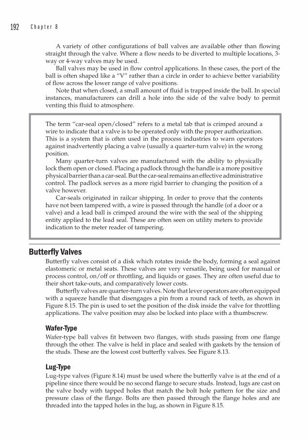
192 C h a p t e r 8
A variety of other configurations of ball valves are available other than flowing straight through the valve. Where a flow needs to be diverted to multiple locations, 3-way or 4-way valves may be used.
Ball valves may be used in flow control applications. In these cases, the port of the ball is often shaped like a “V” rather than a circle in order to achieve better variability of flow across the lower range of valve positions.
Note that when closed, a small amount of fluid is trapped inside the ball. In special instances, manufacturers can drill a hole into the side of the valve body to permit venting this fluid to atmosphere.
The term “car-seal open/closed” refers to a metal tab that is crimped around a wire to indicate that a valve is to be operated only with the proper authorization. This is a system that is often used in the process industries to warn operators against inadvertently placing a valve (usually a quarter-turn valve) in the wrong position.
Many quarter-turn valves are manufactured with the ability to physically lock them open or closed. Placing a padlock through the handle is a more positive physical barrier than a car-seal . But the car-seal remains an effective administrative control. The padlock serves as a more rigid barrier to changing the position of a valve however.
Car-seals originated in railcar shipping. In order to prove that the contents have not been tampered with, a wire is passed through the handle (of a door or a valve) and a lead ball is crimped around the wire with the seal of the shipping entity applied to the lead seal. These are often seen on utility meters to provide indication to the meter reader of tampering.
Butterfly Valves Butterfly valves consist of a disk which rotates inside the body, forming a seal against elastomeric or metal seats . These valves are very versatile, being used for manual or process control, on/off or throttling, and liquids or gases. They are often useful due to their short take-outs, and comparatively lower costs.
Butterfly valves are quarter-turn valves. Note that lever operators are often equipped with a squeeze handle that disengages a pin from a round rack of teeth, as shown in Figure 8.15. The pin is used to set the position of the disk inside the valve for throttling applications. The valve position may also be locked into place with a thumbscrew.
Wafer-Type Wafer-type ball valves fit between two flanges, with studs passing from one flange through the other. The valve is held in place and sealed with gaskets by the tension of the studs. These are the lowest cost butterfly valves. See Figure 8.13.
Lug-Type Lug-type valves (Figure 8.14) must be used where the butterfly valve is at the end of a pipeline since there would be no second flange to secure studs. Instead, lugs are cast on the valve body with tapped holes that match the bolt hole pattern for the size and pressure class of the flange. Bolts are then passed through the flange holes and are threaded into the tapped holes in the lug, as shown in Figure 8.15.
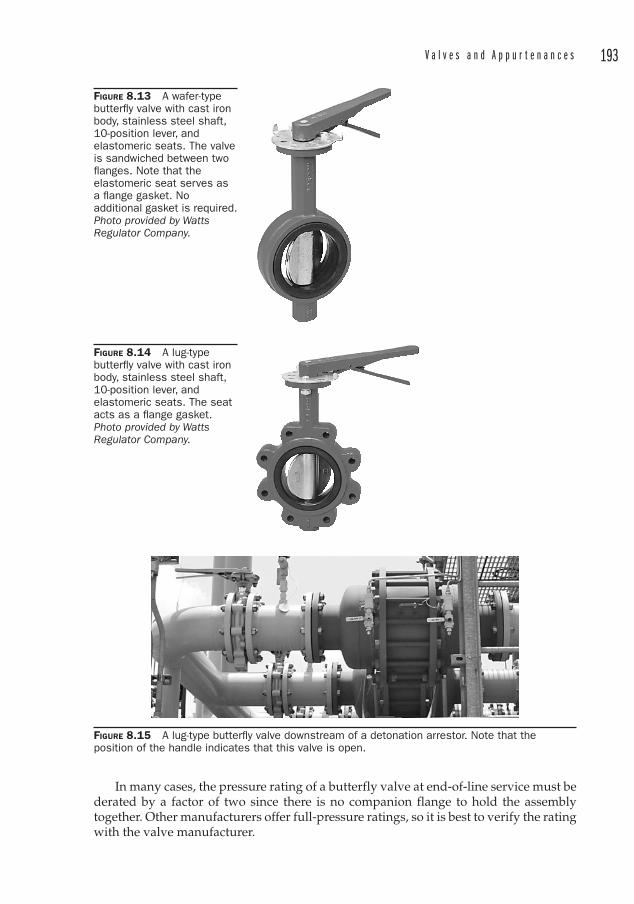
V a l v e s a n d A p p u r t e n a n c e s 193
FIGURE 8.13 A wafer-type butterfl y valve with cast iron body, stainless steel shaft, 10-position lever, and elastomeric seats. The valve is sandwiched between two fl anges. Note that the elastomeric seat serves as a fl ange gasket. No additional gasket is required. Photo provided by Watts Regulator Company.
FIGURE 8.14 A lug-type butterfl y valve with cast iron body, stainless steel shaft, 10-position lever, and elastomeric seats. The seat acts as a fl ange gasket. Photo provided by Watts Regulator Company.
FIGURE 8.15 A lug-type butterfl y valve downstream of a detonation arrestor. Note that the position of the handle indicates that this valve is open.
In many cases, the pressure rating of a butterfly valve at end-of-line service must be derated by a factor of two since there is no companion flange to hold the assembly together. Other manufacturers offer full-pressure ratings, so it is best to verify the rating with the valve manufacturer.
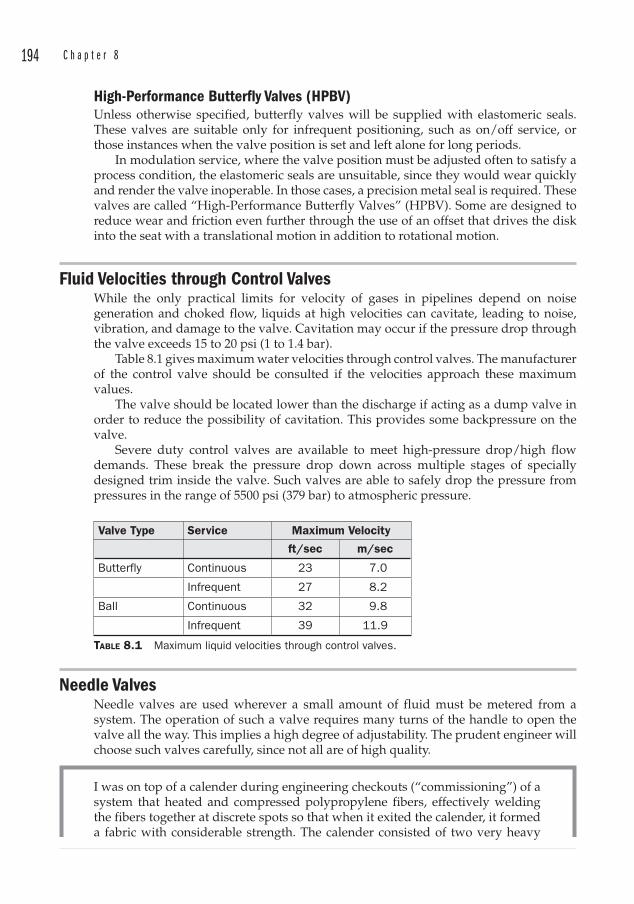
194 C h a p t e r 8
High-Performance Butterfly Valves (HPBV )Unless otherwise specified, butterfly valves will be supplied with elastomeric seals. These valves are suitable only for infrequent positioning, such as on/off service, or those instances when the valve position is set and left alone for long periods.
In modulation service, where the valve position must be adjusted often to satisfy a process condition, the elastomeric seals are unsuitable, since they would wear quickly and render the valve inoperable. In those cases, a precision metal seal is required. These valves are called “High-Performance Butterfly Valves ” (HPBV ). Some are designed to reduce wear and friction even further through the use of an offset that drives the disk into the seat with a translational motion in addition to rotational motion.
Fluid Velocities through Control ValvesWhile the only practical limits for velocity of gases in pipelines depend on noise generation and choked flow, liquids at high velocities can cavitate, leading to noise, vibration, and damage to the valve. Cavitation may occur if the pressure drop through the valve exceeds 15 to 20 psi (1 to 1.4 bar).
Table 8.1 gives maximum water velocities through control valves. The manufacturer of the control valve should be consulted if the velocities approach these maximum values.
The valve should be located lower than the discharge if acting as a dump valve in order to reduce the possibility of cavitation . This provides some backpressure on the valve.
Severe duty control valves are available to meet high-pressure drop/high flow demands. These break the pressure drop down across multiple stages of specially designed trim inside the valve. Such valves are able to safely drop the pressure from pressures in the range of 5500 psi (379 bar) to atmospheric pressure.
Valve Type Service Maximum Velocity
ft/sec m/sec
Butterfly Continuous 23 7.0
Infrequent 27 8.2
Ball Continuous 32 9.8
Infrequent 39 11.9
TABLE 8.1 Maximum liquid velocities through control valves.
Needle Valves Needle valves are used wherever a small amount of fluid must be metered from a system. The operation of such a valve requires many turns of the handle to open the valve all the way. This implies a high degree of adjustability. The prudent engineer will choose such valves carefully, since not all are of high quality.
I was on top of a calender during engineering checkouts (“commissioning”) of a system that heated and compressed polypropylene fibers, effectively welding the fibers together at discrete spots so that when it exited the calender, it formed a fabric with considerable strength. The calender consisted of two very heavy
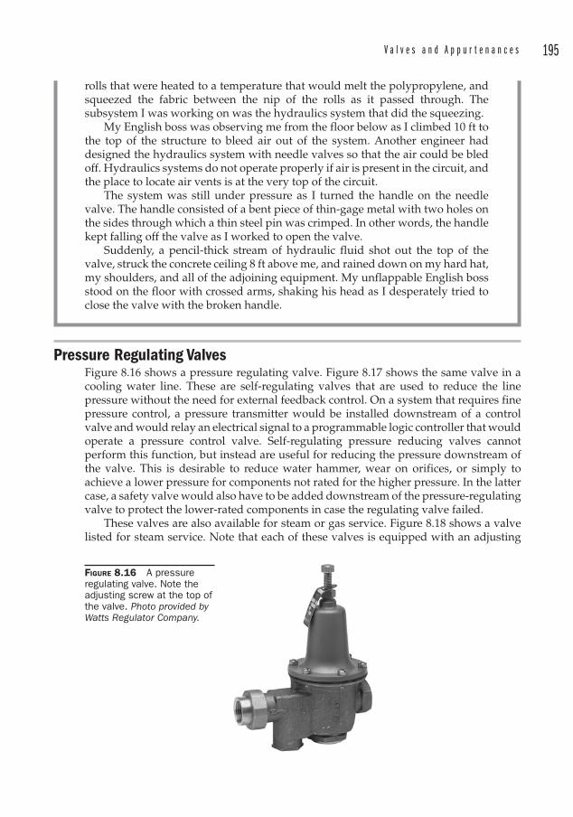
V a l v e s a n d A p p u r t e n a n c e s 195
Pressure Regulating Valves Figure 8.16 shows a pressure regulating valve. Figure 8.17 shows the same valve in a cooling water line. These are self-regulating valves that are used to reduce the line pressure without the need for external feedback control. On a system that requires fine pressure control, a pressure transmitter would be installed downstream of a control valve and would relay an electrical signal to a programmable logic controller that would operate a pressure control valve. Self-regulating pressure reducing valves cannot perform this function, but instead are useful for reducing the pressure downstream of the valve. This is desirable to reduce water hammer, wear on orifices, or simply to achieve a lower pressure for components not rated for the higher pressure. In the latter case, a safety valve would also have to be added downstream of the pressure-regulating valve to protect the lower-rated components in case the regulating valve failed.
These valves are also available for steam or gas service. Figure 8.18 shows a valve listed for steam service. Note that each of these valves is equipped with an adjusting
rolls that were heated to a temperature that would melt the polypropylene, and squeezed the fabric between the nip of the rolls as it passed through. The subsystem I was working on was the hydraulics system that did the squeezing.
My English boss was observing me from the floor below as I climbed 10 ft to the top of the structure to bleed air out of the system. Another engineer had designed the hydraulics system with needle valves so that the air could be bled off. Hydraulics systems do not operate properly if air is present in the circuit, and the place to locate air vents is at the very top of the circuit.
The system was still under pressure as I turned the handle on the needle valve. The handle consisted of a bent piece of thin-gage metal with two holes on the sides through which a thin steel pin was crimped. In other words, the handle kept falling off the valve as I worked to open the valve.
Suddenly, a pencil-thick stream of hydraulic fluid shot out the top of the valve, struck the concrete ceiling 8 ft above me, and rained down on my hard hat, my shoulders, and all of the adjoining equipment. My unflappable English boss stood on the floor with crossed arms, shaking his head as I desperately tried to close the valve with the broken handle.
FIGURE 8.16 A pressure regulating valve. Note the adjusting screw at the top of the valve. Photo provided by Watts Regulator Company.
196 C h a p t e r 8
screw that is used to place more or less tension on an internal spring that fits against a diaphragm. The diaphragm raises or lowers a valve stem, which increases or decreases the orifice size, changing the pressure setting. A pressure gauge located downstream of the valve is required in order to check the set pressure. Note also that the direction in which the screw is turned is counter-intuitive: to increase the pressure, the screw must be turned clockwise; to decrease the pressure, the screw is turned counterclockwise.
Some pressure regulating valves are available with a compensator adjustment control that is used to eliminate hum or chatter within the valve. This may be an important feature for commercial, institutional, or residential applications.
Pressure Relief Valves (PRVs)Pressure vessels are required by the ASME Boiler and Pressure Vessel Code to be protected from overpressurization by relief devices. An overpressure situation may arise from a pump operating out of its expected range of operation, from a fire that raises the temperature and hence the pressure of a closed system, or from a chemical reaction that creates high pressures due to vapor generation. Figure 8.19 shows some typical pressure relief valves.
The purpose of these valves is to relieve pressure in systems in order to prevent damage from overpressure situations. The Boiler and Pressure Vessel Code3 distinguishes among several types of relief valves:
• “Pressure Relief Valve ” is defined as a pressure relief device that is designed to reclose and prevent the further flow of fluid after normal conditions have been restored. This is the generic term that encompasses all four of the following terms.
3 See ASME Section VIII – Division I, UG-125 and UG-126.
FIGURE 8.17 A pressure regulating valve on a cooling water line.
FIGURE 8.18 A pressure regulating valve for steam service. Photo provided by Watts Regulator Company.
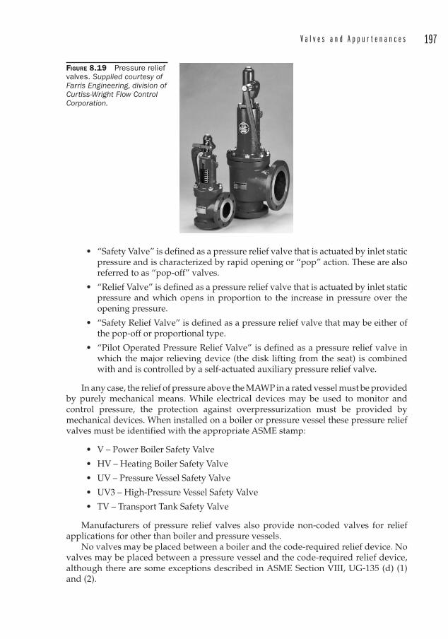
V a l v e s a n d A p p u r t e n a n c e s 197
• “Safety Valve ” is defined as a pressure relief valve that is actuated by inlet static pressure and is characterized by rapid opening or “pop” action. These are also referred to as “pop-off” valves.
• “Relief Valve ” is defined as a pressure relief valve that is actuated by inlet static pressure and which opens in proportion to the increase in pressure over the opening pressure.
• “Safety Relief Valve ” is defined as a pressure relief valve that may be either of the pop-off or proportional type.
• “Pilot Operated Pressure Relief Valve ” is defined as a pressure relief valve in which the major relieving device (the disk lifting from the seat) is combined with and is controlled by a self-actuated auxiliary pressure relief valve.
In any case, the relief of pressure above the MAWP in a rated vessel must be provided by purely mechanical means. While electrical devices may be used to monitor and control pressure, the protection against overpressurization must be provided by mechanical devices. When installed on a boiler or pressure vessel these pressure relief valves must be identified with the appropriate ASME stamp:
• V – Power Boiler Safety Valve
• HV – Heating Boiler Safety Valve
• UV – Pressure Vessel Safety Valve
• UV3 – High-Pressure Vessel Safety Valve
• TV – Transport Tank Safety Valve
Manufacturers of pressure relief valves also provide non-coded valves for relief applications for other than boiler and pressure vessels.
No valves may be placed between a boiler and the code-required relief device. No valves may be placed between a pressure vessel and the code-required relief device, although there are some exceptions described in ASME Section VIII, UG-135 (d) (1) and (2).
FIGURE 8.19 Pressure relief valves. Supplied courtesy of Farris Engineering, division of Curtiss-Wright Flow Control Corporation.

198 C h a p t e r 8
ASME Boiler and Pressure Vessel Code – Section I RequirementsThe number of PRVs on a boiler is set by ASME BPV Section I. Each boiler, regardless of size, shall have at least one safety valve or safety relief valve . If the boiler has over 500 SF (46 m2) of bare tube water heating surface, or if it is an electric boiler with a power input greater than 1100 kW, then it must have two or more safety valves or safety relief valves.
At least one of the safety valves shall be set at or below the MAWP. If additional valves are used, the highest maximum set pressure shall not exceed the MAWP by more than 3 percent. The total range of set pressures of saturated steam on a boiler is not permitted to exceed 10 percent of the highest pressure to which any valve is set. However, the pressure setting of safety relief valves on high-temperature (superheated) water boilers may exceed this 10 percent range.
There are other rules regarding boiler PRVs, and the reader is referred to ASME BPV Code – Section I, PG-67 for details.
In practice, one or more relief valves on a boiler are usually set to a pressure lower than the rest, since this provides early warning (and an additional measure of safety) during a potential overpressure event. Although no isolation valves may be placed upstream of a PRV used to prevent overpressure, a gate valve is sometimes used upstream of an extra PRV known as a “power-control valve. ” The valve is set to blow before any of the others, and because high-pressure steam throttling through a valve orifice can sometimes cut the valve seat, this valve is the “sacrificial” valve and can be isolated and removed for repairs while the system is still in service. The capacity of a power-control valve cannot be used in the relief calculations however, since it may be valved off or out of service.
Section I requires lifting levers on all relief valves except those used in organic fluid vaporizer service. See Figure 8.20 for an example of a relief valve equipped with a test lever.
ASME Boiler and Pressure Vessel Code – Section VIII RequirementsSection VIII of the ASME Code requires pressure relief valves on pressure vessels to have lifting levers for air, steam, and hot water (over 140°F) service, except when all of the following conditions are met:
1. The user has a documented procedure and an associated implementation program for the periodic removal of the relief valve for inspection, testing, and repair.
2. The user specifies that no test lever be supplied.
3. The user obtains permission to omit the lifting lever from the authority having jurisdiction over the installation of a pressure vessel.
OperationRelief valves have a spring that presses the disc against the seat, as shown in the cutaway section of Figure 8.21. When the pressure of the fluid under the seat lifts the disc, the spring force increases in proportion to the amount of lift. Because of this, PRVs are permitted an overpressure allowance of 10 percent of the set pressure to achieve full lift.
Most PRVs are equipped with a secondary chamber, called a “huddling chamber ” which permits the pressurized fluid to act over the total surface area of the disc, rather than the portion exposed by the valve orifice. This permits maximum lift and higher
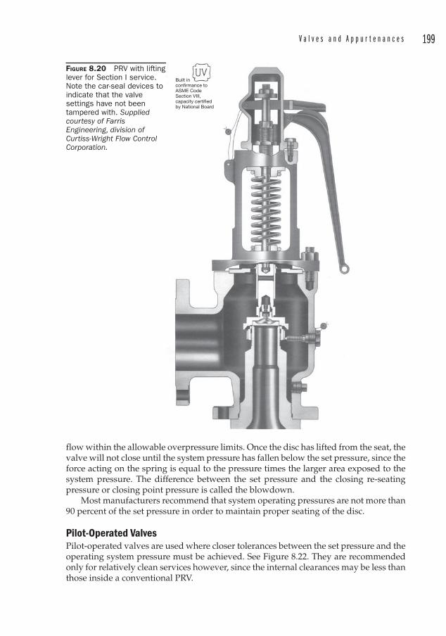
V a l v e s a n d A p p u r t e n a n c e s 199
flow within the allowable overpressure limits. Once the disc has lifted from the seat, the valve will not close until the system pressure has fallen below the set pressure, since the force acting on the spring is equal to the pressure times the larger area exposed to the system pressure. The difference between the set pressure and the closing re-seating pressure or closing point pressure is called the blowdown .
Most manufacturers recommend that system operating pressures are not more than 90 percent of the set pressure in order to maintain proper seating of the disc.
Pilot-Operated Valves Pilot-operated valves are used where closer tolerances between the set pressure and the operating system pressure must be achieved. See Figure 8.22. They are recommended only for relatively clean services however, since the internal clearances may be less than those inside a conventional PRV.
FIGURE 8.20 PRV with lifting lever for Section I service. Note the car-seal devices to indicate that the valve settings have not been tampered with. Suppliedcourtesy of Farris Engineering, division of Curtiss-Wright Flow Control Corporation.
Built inconfirmance toASME Code Section VIII, capacity certified by National Board

200 C h a p t e r 8
The pilot-operated valve has a main valve with a piston or diaphragm operated disc and a pilot line, which allows system pressure into the piston chamber. Because the piston area is larger than the disc seat area, the disc is held closed. When the set pressure is reached, the pilot shuts off the system fluid to the piston chamber and vents the piston chamber. The system pressure can then force the disc to open.
Pilot-operated valves permit the operating pressure to be within 5 percent of the set pressure without increased seat leakage.
FIGURE 8.21 A pressure relief valve for air, gas, or steam service. Supplied courtesy of Farris Engineering, division of Curtiss-Wright Flow Control Corporation.
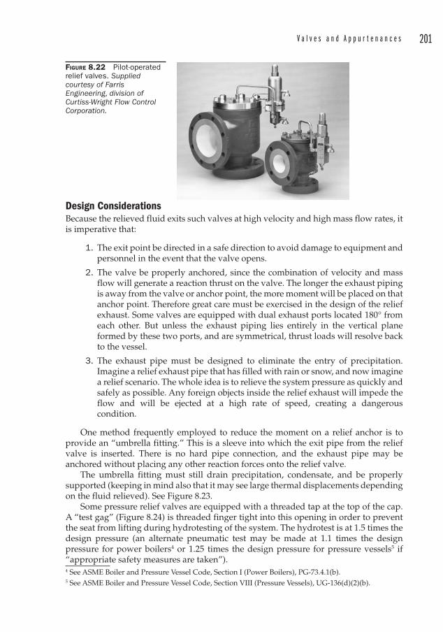
V a l v e s a n d A p p u r t e n a n c e s 201
Design ConsiderationsBecause the relieved fluid exits such valves at high velocity and high mass flow rates, it is imperative that:
1. The exit point be directed in a safe direction to avoid damage to equipment and personnel in the event that the valve opens.
2. The valve be properly anchored, since the combination of velocity and mass flow will generate a reaction thrust on the valve. The longer the exhaust piping is away from the valve or anchor point, the more moment will be placed on that anchor point. Therefore great care must be exercised in the design of the relief exhaust. Some valves are equipped with dual exhaust ports located 180° from each other. But unless the exhaust piping lies entirely in the vertical plane formed by these two ports, and are symmetrical, thrust loads will resolve back to the vessel.
3. The exhaust pipe must be designed to eliminate the entry of precipitation. Imagine a relief exhaust pipe that has filled with rain or snow, and now imagine a relief scenario. The whole idea is to relieve the system pressure as quickly and safely as possible. Any foreign objects inside the relief exhaust will impede the flow and will be ejected at a high rate of speed, creating a dangerous condition.
One method frequently employed to reduce the moment on a relief anchor is to provide an “umbrella fitting. ” This is a sleeve into which the exit pipe from the relief valve is inserted. There is no hard pipe connection, and the exhaust pipe may be anchored without placing any other reaction forces onto the relief valve.
The umbrella fitting must still drain precipitation, condensate, and be properly supported (keeping in mind also that it may see large thermal displacements depending on the fluid relieved). See Figure 8.23.
Some pressure relief valves are equipped with a threaded tap at the top of the cap. A “test gag ” (Figure 8.24) is threaded finger tight into this opening in order to prevent the seat from lifting during hydrotesting of the system. The hydrotest is at 1.5 times the design pressure (an alternate pneumatic test may be made at 1.1 times the design pressure for power boilers4 or 1.25 times the design pressure for pressure vessels5 if “appropriate safety measures are taken”).4 See ASME Boiler and Pressure Vessel Code , Section I (Power Boilers), PG-73.4.1(b). 5 See ASME Boiler and Pressure Vessel Code , Section VIII (Pressure Vessels), UG-136(d)(2)(b).
FIGURE 8.22 Pilot-operatedrelief valves. Suppliedcourtesy of Farris Engineering, division of Curtiss-Wright Flow Control Corporation.
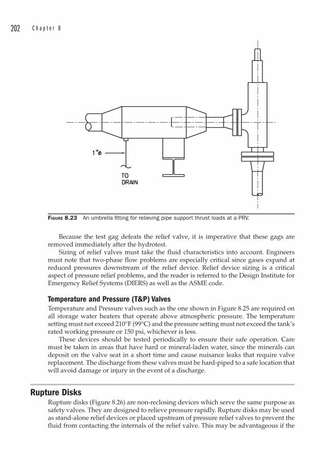
202 C h a p t e r 8
Because the test gag defeats the relief valve, it is imperative that these gags are removed immediately after the hydrotest.
Sizing of relief valves must take the fluid characteristics into account. Engineers must note that two-phase flow problems are especially critical since gases expand at reduced pressures downstream of the relief device. Relief device sizing is a critical aspect of pressure relief problems, and the reader is referred to the Design Institute for Emergency Relief Systems (DIERS ) as well as the ASME code.
Temperature and Pressure (T&P ) ValvesTemperature and Pressure valves such as the one shown in Figure 8.25 are required on all storage water heaters that operate above atmospheric pressure. The temperature setting must not exceed 210°F (99°C) and the pressure setting must not exceed the tank’s rated working pressure or 150 psi, whichever is less.
These devices should be tested periodically to ensure their safe operation. Care must be taken in areas that have hard or mineral-laden water, since the minerals can deposit on the valve seat in a short time and cause nuisance leaks that require valve replacement. The discharge from these valves must be hard-piped to a safe location that will avoid damage or injury in the event of a discharge.
Rupture DisksRupture disks (Figure 8.26) are non-reclosing devices which serve the same purpose as safety valves. They are designed to relieve pressure rapidly. Rupture disks may be used as stand-alone relief devices or placed upstream of pressure relief valves to prevent the fluid from contacting the internals of the relief valve. This may be advantageous if the
FIGURE 8.23 An umbrella fi tting for relieving pipe support thrust loads at a PRV.
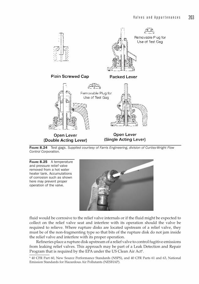
V a l v e s a n d A p p u r t e n a n c e s 203
FIGURE 8.24 Test gags. Supplied courtesy of Farris Engineering, division of Curtiss-Wright Flow Control Corporation.
FIGURE 8.25 A temperature and pressure relief valve removed from a hot water heater tank. Accumulations of corrosion such as shown here may prevent proper operation of the valve.
fluid would be corrosive to the relief valve internals or if the fluid might be expected to collect on the relief valve seat and interfere with its operation should the valve be required to relieve. Where rupture disks are located upstream of a relief valve, they must be of the non-fragmenting type so that bits of the rupture disk do not jam inside the relief valve and interfere with its proper operation.
Refineries place a rupture disk upstream of a relief valve to control fugitive emissions from leaking relief valves. This approach may be part of a Leak Detection and Repair Program that is required by the EPA under the US Clean Air Act 6.6 40 CFR Part 60, New Source Performance Standards (NSPS), and 40 CFR Parts 61 and 63, National Emission Standards for Hazardous Air Pollutants (NESHAP).
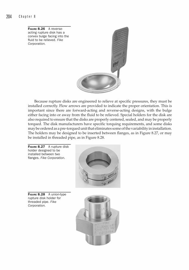
204 C h a p t e r 8
Because rupture disks are engineered to relieve at specific pressures, they must be installed correctly. Flow arrows are provided to indicate the proper orientation. This is important since there are forward-acting and reverse-acting designs, with the bulge either facing into or away from the fluid to be relieved. Special holders for the disk are also required to ensure that the disks are properly centered, sealed, and may be properly torqued. The disk manufacturers have specific torquing requirements, and some disks may be ordered as a pre-torqued unit that eliminates some of the variability in installation. The holders may be designed to be inserted between flanges, as in Figure 8.27, or may be installed in threaded pipe, as in Figure 8.28.
FIGURE 8.26 A reverse-acting rupture disk has a convex bulge facing into the fl uid to be relieved. Fike Corporation.
FIGURE 8.27 A rupture disk holder designed to be installed between two fl anges. Fike Corporation.
FIGURE 8.28 A union-type rupture disk holder for threaded pipe. Fike Corporation.
V a l v e s a n d A p p u r t e n a n c e s 205
ASME Requirements for Rupture DisksThe tolerance for burst pressure must not exceed ± 2 psi for marked pressures up to and including 40 psi, and ± 5 percent for marked pressures above 40 psi.
There are three methods permitted by ASME for acceptance testing of rupture disks. The most common method requires that at least two disks from each manufacturing lot be burst tested at the specified disk temperature. The disks must burst within the rupture tolerance.
Rupture disks are marked with the ASME UD symbol.
Design ConsiderationsThe following parameters must be considered when specifying a rupture disk:
• Normal operating pressure
• Maximum Allowable Working Pressure of the vessel to be protected
• Cyclic pressure duty
• Exposure to vacuum
• Chemical compatibility between the disk and the fluid
• Normal operating temperature
• Maximum operating temperature
• Fluid characteristics such as polymerization, liquid, gas, or two-phase flow
Just like other safety relief devices, the exhaust from a rupture disk must be vented to a safe location.
Valve Leakage No valve is completely leak-proof, and leakage is a relative term. The industry has adopted standards to quantify the amount of leakage through control valves. These standards are set forth in ANSI/FCI 70-2.
The extent to which a particular valve leaks depends on several variables:
• The number of seats . A butterfly valve has two seats and this reduces its ability to seal completely around the axis of rotation of the disk.
• Greater actuator thrust (or torque) will seal more tightly.
• Higher pressure drop across the valve sealing surface will promote leakage.
• Low surface tension liquids will leak more easily, as will gases.
ANSI/FCI 70-2 defines six classifications of valve seat leakage, but for most applications only two are commonly used: Class IV is a metal-to-metal seal and Class VI is a soft-seat seal (in which either the plug7 or seat or both are made of a resilient material).
The complete classification system is:
• Class I is identical to Classes II, III, and IV in construction and design, but no shop tests are performed if the user and the supplier agree. There is no maximum leakage allowable set for this classification of valves.
7 In this context, “plug” may refer to a disk, a ball, or a plug (as in a plug valve).
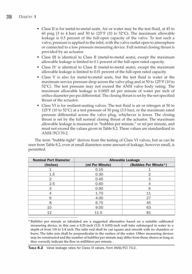
206 C h a p t e r 8
• Class II is for metal-to-metal seats . Air or water may be the test fluid, at 45 to 60 psig (3 to 4 bar) and 50 to 125°F (10 to 52°C). The maximum allowable leakage is 0.5 percent of the full-open capacity of the valve. To test such a valve, pressure is applied to the inlet, with the valve outlet open to atmosphere or connected to a low pressure measuring device. Full normal closing thrust is provided by an actuator.
• Class III is identical to Class II (metal-to-metal seats ), except the maximum allowable leakage is limited to 0.1 percent of the full-open rated capacity.
• Class IV is identical to Class II (metal-to-metal seats ), except the maximum allowable leakage is limited to 0.01 percent of the full-open rated capacity.
• Class V is also for metal-to-metal seats , but the test fluid is water at the maximum service pressure drop across the valve plug and at 50 to 125°F (10 to 52°C). The test pressure may not exceed the ANSI valve body rating. The maximum allowable leakage is 0.0005 ml per minute of water per inch of orifice diameter per psi differential. The closing thrust is set by the net specified thrust of the actuator.
• Class VI is for resilient-seating valves. The test fluid is air or nitrogen at 50 to 125°F (10 to 52°C) at a test pressure of 50 psig (3.5 bar), or the maximum rated pressure differential across the valve plug, whichever is lower. The closing thrust is set by the full normal closing thrust of the actuator. The maximum allowable leakage is measured in “bubbles per minute,” or ml per minute, and must not exceed the values given in Table 8.2. These values are standardized in ANSI/FCI 70-2.
The term “bubble-tight ” derives from the testing of Class VI valves, but as can be seen from Table 8.2, even at small diameters some amount of leakage, however small, is permitted.
Nominal Port Diameter Allowable Leakage(Inches) (ml Per Minute) (Bubbles Per Minute*)
1 0.15 1 1.5 0.30 2 2 0.45 3 2.5 0.60 4 3 0.90 6 4 1.70 11 6 4.00 27 8 6.75 45 10 9.00 63 12 11.5 81
* Bubbles per minute as tabulated are a suggested alternative based on a suitable calibrated measuring device, in this case a 0.25-inch O.D. X 0.032-inch wall tube submerged in water to a depth of from 1/8 to 1/4 inch. The tube end shall be cut square and smooth with no chamfers or burrs. The tube axis shall be perpendicular to the surface of the water. Other measuring devices may be constructed and the number of bubbles per minute may differ from those shown as long as they correctly indicate the flow in milliliters per minute.
TABLE 8.2 Valve leakage rates for Class VI valves, from ANSI/FCI 70-2.
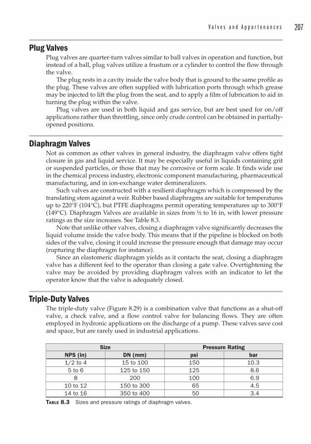
V a l v e s a n d A p p u r t e n a n c e s 207
Plug Valves Plug valves are quarter-turn valves similar to ball valves in operation and function, but instead of a ball, plug valves utilize a frustum or a cylinder to control the flow through the valve.
The plug rests in a cavity inside the valve body that is ground to the same profile as the plug. These valves are often supplied with lubrication ports through which grease may be injected to lift the plug from the seat, and to apply a film of lubrication to aid in turning the plug within the valve.
Plug valves are used in both liquid and gas service, but are best used for on/off applications rather than throttling, since only crude control can be obtained in partially-opened positions.
Diaphragm Valves Not as common as other valves in general industry, the diaphragm valve offers tight closure in gas and liquid service. It may be especially useful in liquids containing grit or suspended particles, or those that may be corrosive or form scale. It finds wide use in the chemical process industry, electronic component manufacturing, pharmaceutical manufacturing, and in ion-exchange water demineralizers.
Such valves are constructed with a resilient diaphragm which is compressed by the translating stem against a weir. Rubber based diaphragms are suitable for temperatures up to 220°F (104°C), but PTFE diaphragms permit operating temperatures up to 300°F (149°C). Diaphragm Valves are available in sizes from ½ to 16 in, with lower pressure ratings as the size increases. See Table 8.3.
Note that unlike other valves, closing a diaphragm valve significantly decreases the liquid volume inside the valve body. This means that if the pipeline is blocked on both sides of the valve, closing it could increase the pressure enough that damage may occur (rupturing the diaphragm for instance).
Since an elastomeric diaphragm yields as it contacts the seat, closing a diaphragm valve has a different feel to the operator than closing a gate valve. Overtightening the valve may be avoided by providing diaphragm valves with an indicator to let the operator know that the valve is adequately closed.
Triple-Duty Valves The triple-duty valve (Figure 8.29) is a combination valve that functions as a shut-off valve, a check valve, and a flow control valve for balancing flows. They are often employed in hydronic applications on the discharge of a pump. These valves save cost and space, but are rarely used in industrial applications.
Size Pressure RatingNPS (in) DN (mm) psi bar1/2 to 4 15 to 100 150 10.35 to 6 125 to 150 125 8.6
8 200 100 6.910 to 12 150 to 300 65 4.514 to 16 350 to 400 50 3.4
TABLE 8.3 Sizes and pressure ratings of diaphragm valves.
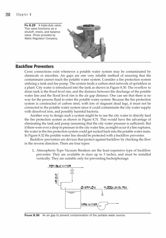
208 C h a p t e r 8
Backflow Preventers Cross connections exist whenever a potable water system may be contaminated by chemicals or microbes. Air gaps are one very reliable method of ensuring that the contaminant cannot reach the potable water system. Consider a fire protection system utilizing a tank and fire pump. The system feeds a carbon steel network of sprinklers in a plant. City water is introduced into the tank as shown in Figure 8.30. The overflow to drain tank is the flood level rim, and the distance between the discharge of the potable water line and the flood level rim is the air gap distance. One can see that there is no way for the process fluid to enter the potable water system. Because the fire protection system is constructed of carbon steel, with lots of stagnant dead legs, it must not be connected to the potable water system since it could contaminate the city water supply with dissolved iron, and possibly harmful bacteria.
Another way to design such a system might be to use the city water to directly feed the fire protection system as shown in Figure 8.31. This would have the advantage of eliminating the tank and pump (assuming that the city water pressure is sufficient). But if there were ever a drop in pressure in the city water line, as might occur if a line ruptures, the water in the fire protection system could get sucked back into the potable water main. In Figure 8.32 the potable water line should be protected with a backflow preventer.
Backflow preventers are devices that protect against backflow by checking the flow in the reverse direction. There are four types:
1. Atmospheric-Type Vacuum Breakers are the least expensive type of backflow preventer. They are available in sizes up to 3 inches, and must be installed vertically. They are suitable only for preventing backsiphonage.
FIG 8.29 A triple-duty valve. This valve functions as a shutoff, check, and balance valve. Photo provided by Watts Regulator Company.
FIGURE 8.30 An air gap to prevent contamination of the potable water source.
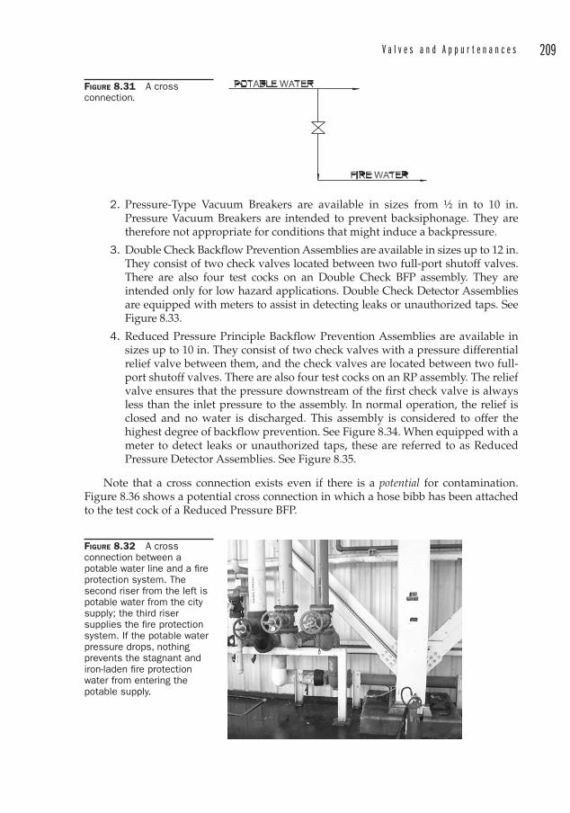
V a l v e s a n d A p p u r t e n a n c e s 209
2. Pressure-Type Vacuum Breakers are available in sizes from ½ in to 10 in. Pressure Vacuum Breakers are intended to prevent backsiphonage. They are therefore not appropriate for conditions that might induce a backpressure.
3. Double Check Backflow Prevention Assemblies are available in sizes up to 12 in. They consist of two check valves located between two full-port shutoff valves. There are also four test cocks on an Double Check BFP assembly. They are intended only for low hazard applications. Double Check Detector Assemblies are equipped with meters to assist in detecting leaks or unauthorized taps. See Figure 8.33.
4. Reduced Pressure Principle Backflow Prevention Assemblies are available in sizes up to 10 in. They consist of two check valves with a pressure differential relief valve between them, and the check valves are located between two full-port shutoff valves. There are also four test cocks on an RP assembly. The relief valve ensures that the pressure downstream of the first check valve is always less than the inlet pressure to the assembly. In normal operation, the relief is closed and no water is discharged. This assembly is considered to offer the highest degree of backflow prevention. See Figure 8.34. When equipped with a meter to detect leaks or unauthorized taps, these are referred to as Reduced Pressure Detector Assemblies. See Figure 8.35.
Note that a cross connection exists even if there is a potential for contamination. Figure 8.36 shows a potential cross connection in which a hose bibb has been attached to the test cock of a Reduced Pressure BFP.
FIGURE 8.31 A cross connection.
FIGURE 8.32 A cross connection between a potable water line and a fi re protection system. The second riser from the left is potable water from the city supply; the third riser supplies the fi re protection system. If the potable water pressure drops, nothing prevents the stagnant and iron-laden fi re protection water from entering the potable supply.
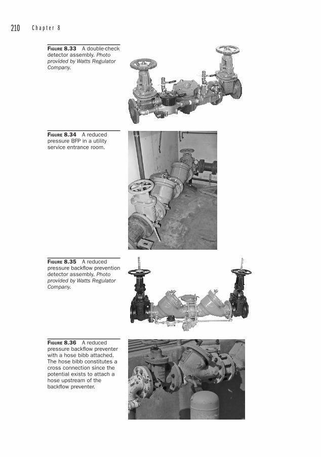
210 C h a p t e r 8
FIGURE 8.33 A double-check detector assembly. Photoprovided by Watts Regulator Company.
FIGURE 8.34 A reduced pressure BFP in a utility service entrance room.
FIGURE 8.35 A reduced pressure backfl ow prevention detector assembly. Photoprovided by Watts Regulator Company.
FIGURE 8.36 A reduced pressure backfl ow preventer with a hose bibb attached. The hose bibb constitutes a cross connection since the potential exists to attach a hose upstream of the backfl ow preventer.
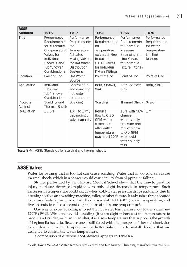
V a l v e s a n d A p p u r t e n a n c e s 211
ASSE Valves Water for bathing that is too hot can cause scalding . Water that is too cold can cause thermal shock , which in a shower could cause injury from slipping or falling.
Studies performed by the Harvard Medical School show that the time to produce injury to tissue decreases rapidly with only slight increases in temperature. Such increases in temperature could occur when cold-water pressure drops suddenly due to opening a valve on a washing machine, toilet, or other fixture. It only takes three seconds to cause a first-degree burn on adult skin tissue at 140°F (60°C) water temperature, and five seconds to cause a second degree burn at the same temperature8.
One way to avoid scalding is to set the hot water temperature to a lower value, say 120°F (49°C). While this avoids scalding (it takes eight minutes at this temperature to produce a first degree burn in adults), it is also a temperature that supports the growth of Legionella bacteria. Because one is still faced with the prospect of thermal shock due to sudden cold water temperatures, a better solution is to install devices that are designed to control the water temperature.
A comparison of different ASSE devices appears in Table 8.4.
8 Viola, David W. 2002, “Water Temperature Control and Limitation,” Plumbing Manufacturers Institute.
ASSEStandard 1016 1017 1062 1066 1070Title Performance
Requirementsfor Automatic CompensatingValves for IndividualShowers and Tub/Shower Combinations
Performance RequirementsforTemperature ActuatedMixing Valves for Hot Water DistributionSystems
Performance RequirementsforTemperature Actuated, Flow Reduction(TAFR) Valves for Individual Fixture Fittings
Performance Requirementsfor Individual PressureBalancing In-Line Valves for Individual Fixture Fittings
Performance Requirementsfor Water Temperature LimitingDevices
Location Point-of-Use Hot Water Source
Point-of-Use Point-of-Use Point-of-Use
Application Individual Tubs and Tub/ Shower Combinations
Control of in-line domestic hot water temperature
Bath, Shower, Sink
Bath, Shower, Sink
Bath, Sink
ProtectsAgainst
Scalding and Thermal Shock
Scalding Scalding Thermal Shock Scald
Regulation ±3.6°F ±3°F to ±7°F, depending on valve capacity
Reduceflow to 0.25 GPM within 5 seconds after outlet temperaturereaches 120°F
±3°F with 50% change in water supply pressure and reduces flow to 0.5 GPM when cold water supply fails
±7°F
TABLE 8.4 ASSE Standards for scalding and thermal shock.
212 C h a p t e r 8
ASSE 1016 Control ValvesThese devices are used to provide scald and thermal shock protection at showers and bathtubs. In order to be listed as an ASSE 1016 valve, the device must be controllable by the bather and have an adjustable maximum temperature limit that is set by the installer (and may be later adjusted by the owner). The flow rate must also reduce to 0.5 GPM (1.9 l/min) if the cold water stops flowing to the valve.
The valve must maintain the desired outlet temperature within a range of 3.6°F (±2.0°C).
ASSE 1017 Control ValvesValves manufactured to this standard are used to reduce temperature throughout the hot water distribution system. These are mixing valves located at the water-heating source rather than at the end use fixture. In the absence of other preventive measures, one should keep in mind that the Legionella bacteria do not die rapidly until temperatures reach 131°F (55°C).
ASSE 1016 valves should be used in conjunction with ASSE 1017 valves to prevent scalding .
ASSE 1062 Temperature Actuated Flow Reduction (TAFR) Valves TAFR valves reduce the risk of scalding by restricting flow when the temperature exceeds a preset limit. The maximum limit is 120°F (49°C). These are point-of-use devices either integral to the fixture or available as an add-on after installation.
ASSE 1066 Pressure Balancing In-Line Valves These valves are for preventing thermal shock on individual fixtures. The discharge temperature is permitted to vary 3 degrees from the set temperature when incoming water pressure changes 50 percent. While not designed specifically to prevent scalding , the flow through these devices is to be reduced to 0.5 GPM or less whenever the cold water supply fails.
ASSE 1070 Water Temperature Limiting DevicesThese valves are for individual or multiple fixtures and protect against scalding . ASSE 1070 valves do not apply to showers.
Steam Traps Steam traps remove condensate and noncondensibles (air) from steam lines. If sufficient pressure is available in the live steam line, the condensate can be pushed back to the boiler room without the need for condensate pumps. If the condensate is sufficiently clean, it is preferred to return it to the boiler for heat reclaim and re-use as boiler feedwater. Boiler feedwater is costly to create due to both the heat-up of the water and the treatments and chemicals required to maintain a clean steam system. Demineralization and/or anti-scaling treatments are required since minerals inside a steam system are essentially thermal insulators. Thus, an excellent place to save money in a plant is in the return of clean condensate back to the boiler.
Float Traps A chamber contains a float that is on a linkage. As the chamber fills with condensate, the level rises until the float trips open a valve that expels the condensate. These are
V a l v e s a n d A p p u r t e n a n c e s 213
equipped with a thermostatic air vent to vent noncondensibles that become trapped within the chamber. Noncondensibles would displace steam inside the trap and prevent the formation of condensate.
Advantages
• Able to handle a wide range of condensate loads across a wide range of pressures and flows
• Large load capacity for its size• Discharges condensate at essentially the same temperature as the steam• Resistant to water hammer
Disadvantages
• Susceptible to freezing
Inverted Bucket TrapsThe condensate flow into an inverted bucket trap is from the bottom. Inside the trap chamber an upside-down bucket hangs from a lever that is attached to a valve internal to the trap. When steam enters the trap, the bucket becomes buoyant and floats up to close the valve until the steam condenses.
A small hole at the top of the bucket permits air to be vented through the trap also.
Advantages
• Can withstand high pressure• Resistant to water hammer• Fails open, so it is safer for certain applications like turbine drains• May be used on superheated steam by adding a check valve on the inlet
Disadvantages
• Bleeds-off noncondensibles very slowly• Must use an inlet check valve if steam pressure fluctuates• If trap loses water seal around the rim of the inverted bucket, steam is wasted.
This can happen if there is a sudden loss of steam pressure that flashes the condensate to steam
Liquid Expansion TrapThis type of trap contains an oil-filled element that expands when steam enters the chamber. This seats a valve until the steam condenses, and then the oil-filled element contracts, pulling the disk away from the seat to allow the condensate to be expelled.
Advantages
• Can be manufactured to discharge at lower temperatures• Excellent at discharging air and condensate during warm-up• Withstands vibration and water hammer
Disadvantages
• Flexible element is susceptible to corrosion• Not quick-acting

214 C h a p t e r 8
• May freeze
• Must usually be applied in parallel with another type of trap
Balanced Pressure TrapSimilar to the liquid expansion trap, the balanced pressure trap contains a sealed compartment that is filled with a solution with a boiling point lower than that of water. During start-up the valve is wide open so that air is easily vented. When condensate surrounds the sealed compartment the liquid contained inside vaporizes and expands the compartment, which seats an internal valve. Once the condensate cools, the vapor in the sealed compartment condenses and opens the valve to expel the condensate. This in turn allows steam to enter the trap and the liquid inside the sealed compartment again vaporizes.
Advantages
• Full open on start-up permits venting of noncondensibles and large condensate loads
• Not susceptible to freezing
• Suitable for varying steam pressure
• Can withstand superheat
• Easily maintained.
Disadvantages
• Bellows style traps are prone to failure from corrosion and water hammer. (Sealed compartments of welded stainless steel are better under these conditions).
• Does not evacuate condensate until condensate temperature drops below the steam temperature. This can lead to waterlogging.
Bimetallic TrapsBimetallic discs inside these traps deflect due to temperature changes. This movement lifts a valve from the seat causing the condensate to be expelled. Because the forces exerted by bimetallic strips are small, a large mass must be used to exert enough force to lift the valve from the seat. The increased mass makes the bimetallic strip slow to react.
Some bimetallic traps are manufactured to produce a quick blast discharge, which helps to clear dirt from the internals.
Advantages
• Large condensate capacity
• Full open on start-up permits venting of noncondensibles and large condensate loads
• Not susceptible to freezing
• Withstands water hammer, corrosive condensate, and high steam pressures
• Easy to maintain without removing trap from the line.
V a l v e s a n d A p p u r t e n a n c e s 215
Disadvantages
• A separate check valve may be required downstream of the trap if reverse flow is possible
• Waterlogging of the steam space will occur unless the steam trap is installed at the end of a 3 to 10 ft (1 to 3 m) long uninsulated cooling leg
• May be blocked by dirt due to low flows through the trap, although good practice indicates that traps be installed with strainers upstream
• Bimetallic steam traps do not respond quickly to changes in load or pressure due to the slow reaction time of the thermal mass of the bimetallic element.
Thermodynamic TrapsThe thermodynamic trap has a small condensing chamber above a single disc that is permitted to rise and fall above another chamber that admits condensate. The hot condensate flashes to steam as it leaves the trap and some of this steam remains above the disc, seating it against the condensate chamber below. When this steam condenses, the condensate pressure below forces the disc open, and the cycle repeats.
Advantages
• Large condensate capacity
• Not susceptible to water hammer or vibration
• Not susceptible to corrosion or superheat
• Not damaged by freezing, and can even be freeze-proofed if installed with the disc in the vertical plane
• Easily maintained with trap in-line
• Clicking noise of disc opening and closing indicates proper operation.
Disadvantages
• Pressure drop across the trap must be sufficient for condensate to flash to steam.
• High-velocity air on start-up will cause trap to close and air-bind. A separate thermostatic air vent must be piped in parallel with the trap to alleviate this condition or the trap can be ordered with an integral anti-air-binding disc.
• Noise caused by clicking of the trap may prevent its use in some environments, although diffusers that reduce the noise can be fitted to the trap.
• Oversizing the trap will increase cycle time and subsequent wear.
Prior to start-up, steam lines must be blown to atmosphere, bypassing the steam traps. It is imperative that the oils, lacquers, mill scale, etc. that are present in an installed steam line are eliminated by bringing the lines to temperature and blowing them down with steam. If this is not accomplished, then the traps will clog and be rendered useless. This could lead to other problems such as water hammer.
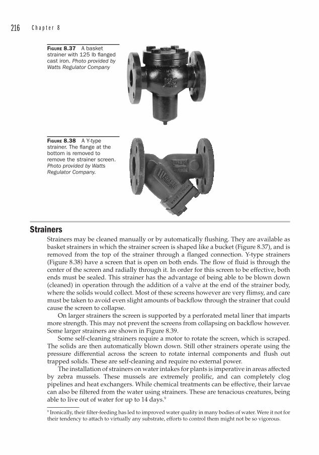
216 C h a p t e r 8
Strainers Strainers may be cleaned manually or by automatically flushing. They are available as basket strainers in which the strainer screen is shaped like a bucket (Figure 8.37), and is removed from the top of the strainer through a flanged connection. Y-type strainers (Figure 8.38) have a screen that is open on both ends. The flow of fluid is through the center of the screen and radially through it. In order for this screen to be effective, both ends must be sealed. This strainer has the advantage of being able to be blown down (cleaned) in operation through the addition of a valve at the end of the strainer body, where the solids would collect. Most of these screens however are very flimsy, and care must be taken to avoid even slight amounts of backflow through the strainer that could cause the screen to collapse.
On larger strainers the screen is supported by a perforated metal liner that imparts more strength. This may not prevent the screens from collapsing on backflow however. Some larger strainers are shown in Figure 8.39.
Some self-cleaning strainers require a motor to rotate the screen, which is scraped. The solids are then automatically blown down. Still other strainers operate using the pressure differential across the screen to rotate internal components and flush out trapped solids. These are self-cleaning and require no external power.
The installation of strainers on water intakes for plants is imperative in areas affected by zebra mussels. These mussels are extremely prolific, and can completely clog pipelines and heat exchangers. While chemical treatments can be effective, their larvae can also be filtered from the water using strainers. These are tenacious creatures, being able to live out of water for up to 14 days.9
9 Ironically, their filter-feeding has led to improved water quality in many bodies of water. Were it not for their tendency to attach to virtually any substrate, efforts to control them might not be so vigorous.
FIGURE 8.37 A basket strainer with 125 lb fl anged cast iron. Photo provided by Watts Regulator Company
FIGURE 8.38 A Y-type strainer. The fl ange at the bottom is removed to remove the strainer screen. Photo provided by Watts Regulator Company.
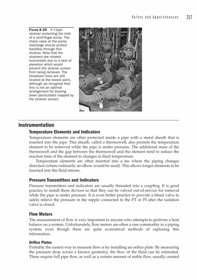
V a l v e s a n d A p p u r t e n a n c e s 217
InstrumentationTemperature Elements and IndicatorsTemperature elements are often protected inside a pipe with a metal sheath that is inserted into the pipe. This sheath, called a thermowell, also permits the temperature element to be removed while the pipe is under pressure. The additional mass of the thermowell and the gap between the thermowell and the element tend to reduce the reaction time of the element to changes in fluid temperature.
Temperature elements are often inserted into a tee where the piping changes direction (where ordinarily an elbow would be used). This allows longer elements to be inserted into the fluid stream.
Pressure Transmitters and IndicatorsPressure transmitters and indicators are usually threaded into a coupling. It is good practice to install these devices so that they can be valved out-of-service for removal while the pipe is under pressure. It is even better practice to provide a bleed valve to safely relieve the pressure in the nipple connected to the PT or PI after the isolation valve is closed.
Flow Meters The measurement of flow is very important to anyone who attempts to perform a heat balance on a system. Unfortunately, flow meters are often a rare commodity in a piping system, even though there are quite economical methods of capturing this information.
Orifice Plates Probably the easiest way to measure flow is by installing an orifice plate. By measuring the pressure drop across a known geometry, the flow of the fluid can be estimated. These require full pipe flow, as well as a certain amount of stable flow, usually created
FIGURE 8.39 A Y-type strainer protecting the inlet of a centrifugal pump. The check valve at the pump discharge should protect backfl ow through this strainer. Note that the strainers are rotated horizontally due to a lack of elevation which would prevent the strainer screen from being removed. The blowdown lines are still located at the lowest point, although we recognize that this is not an optimal arrangement for blowing down particulates trapped by the strainer screen.
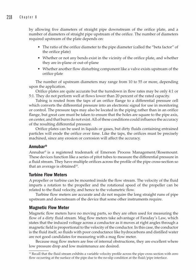
218 C h a p t e r 8
by allowing five diameters of straight pipe downstream of the orifice plate, and a number of diameters of straight pipe upstream of the orifice. The number of diameters required upstream of the plate depends on:
• The ratio of the orifice diameter to the pipe diameter (called the “beta factor” of the orifice plate)
• Whether or not any bends exist in the vicinity of the orifice plate, and whether they are in-plane or out-of-plane
• Whether another flow disturbing component like a valve exists upstream of the orifice plate
The number of upstream diameters may range from 10 to 55 or more, depending upon the application.
Orifice plates are quite accurate but the turndown in flow rates may be only 4:1 or 5:1. They do not perform well at flows lower than 20 percent of the rated capacity.
Tubing is routed from the taps of an orifice flange to a differential pressure cell which converts the differential pressure into an electronic signal for use in monitoring or control. The pressure taps may also be located in the piping rather than in an orifice flange, but great care must be taken to ensure that the holes are square to the pipe axis, on center, and that burrs do not exist. All of these conditions could influence the accuracy of the resulting differential pressure.
Orifice plates can be used in liquids or gases, but dirty fluids containing entrained particles will erode the orifice over time. Like the taps, the orifices must be precisely machined, since any erosion or corrosion will affect the accuracy.
Annubar®Annubar® is a registered trademark of Emerson Process Management/Rosemount. These devices function like a series of pitot tubes to measure the differential pressure in a fluid stream. They have multiple orifices across the profile of the pipe cross-section so that an average is obtained10.
Turbine Flow Meters A propeller or turbine can be mounted inside the flow stream. The velocity of the fluid imparts a rotation to the propeller and the rotational speed of the propeller can be related to the fluid velocity, and hence to the volumetric flow.
Turbine flow meters are accurate and do not require the long straight runs of pipe upstream and downstream of the device that some other instruments require.
Magnetic Flow MeterMagnetic flow meters have no moving parts, so they are often used for measuring the flow of a dirty fluid stream. Mag flow meters take advantage of Faraday’s Law, which states that the induced voltage across a conductor as it moves at right angles through a magnetic field is proportional to the velocity of the conductor. In this case, the conductor is the fluid itself, so fluids with poor conductance like hydrocarbons and distilled water are not good candidates for measuring with a mag flow meter.
Because mag flow meters are free of internal obstructions, they are excellent where low pressure drop and low maintenance are desired.
10 Recall that the fluid stream exhibits a variable velocity profile across the pipe cross section with zero flow occurring at the surface of the pipe due to the no-slip condition at the fluid/pipe interface.
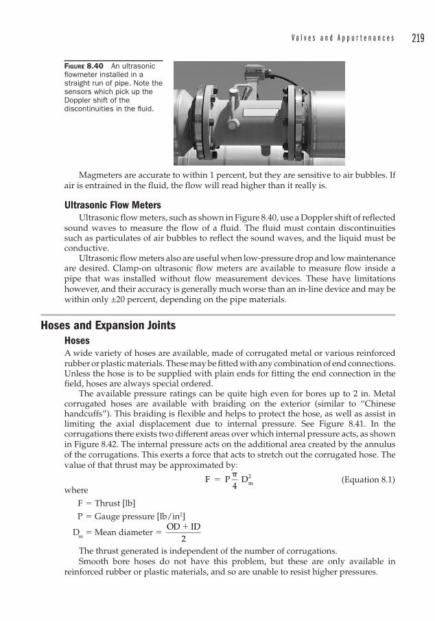
V a l v e s a n d A p p u r t e n a n c e s 219
Magmeters are accurate to within 1 percent, but they are sensitive to air bubbles. If air is entrained in the fluid, the flow will read higher than it really is.
Ultrasonic Flow Meters Ultrasonic flow meters, such as shown in Figure 8.40, use a Doppler shift of reflected
sound waves to measure the flow of a fluid. The fluid must contain discontinuities such as particulates of air bubbles to reflect the sound waves, and the liquid must be conductive.
Ultrasonic flow meters also are useful when low-pressure drop and low maintenance are desired. Clamp-on ultrasonic flow meters are available to measure flow inside a pipe that was installed without flow measurement devices. These have limitations however, and their accuracy is generally much worse than an in-line device and may be within only ±20 percent, depending on the pipe materials.
Hoses and Expansion Joints HosesA wide variety of hoses are available, made of corrugated metal or various reinforced rubber or plastic materials. These may be fitted with any combination of end connections. Unless the hose is to be supplied with plain ends for fitting the end connection in the field, hoses are always special ordered.
The available pressure ratings can be quite high even for bores up to 2 in. Metal corrugated hoses are available with braiding on the exterior (similar to “Chinese handcuffs”). This braiding is flexible and helps to protect the hose, as well as assist in limiting the axial displacement due to internal pressure. See Figure 8.41. In the corrugations there exists two different areas over which internal pressure acts, as shown in Figure 8.42. The internal pressure acts on the additional area created by the annulus of the corrugations. This exerts a force that acts to stretch out the corrugated hose. The value of that thrust may be approximated by:
F P4
Dm2�
� (Equation 8.1)
where
F � Thrust [lb]
P � Gauge pressure [lb/in2]
Dm � Mean diameter � OD ID
2�
The thrust generated is independent of the number of corrugations.Smooth bore hoses do not have this problem, but these are only available in
reinforced rubber or plastic materials, and so are unable to resist higher pressures.
FIGURE 8.40 An ultrasonic fl owmeter installed in a straight run of pipe. Note the sensors which pick up the Doppler shift of the discontinuities in the fl uid.
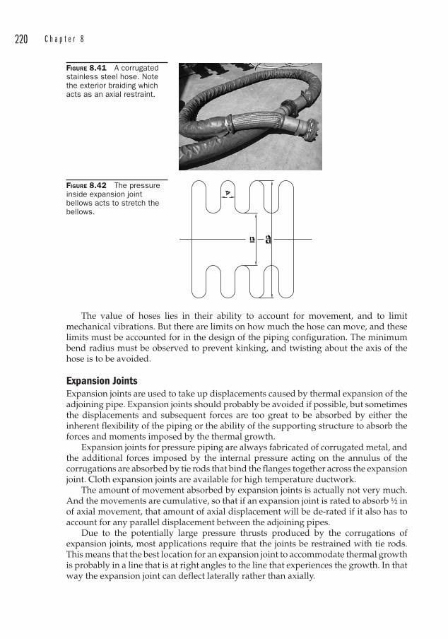
220 C h a p t e r 8
The value of hoses lies in their ability to account for movement, and to limit mechanical vibrations. But there are limits on how much the hose can move, and these limits must be accounted for in the design of the piping configuration. The minimum bend radius must be observed to prevent kinking, and twisting about the axis of the hose is to be avoided.
Expansion JointsExp ansion joints are used to take up displacements caused by thermal expansion of the adjoining pipe. Expansion joints should probably be avoided if possible, but sometimes the displacements and subsequent forces are too great to be absorbed by either the inherent flexibility of the piping or the ability of the supporting structure to absorb the forces and moments imposed by the thermal growth.
Expansion joints for pressure piping are always fabricated of corrugated metal, and the additional forces imposed by the internal pressure acting on the annulus of the corrugations are absorbed by tie rods that bind the flanges together across the expansion joint. Cloth expansion joints are available for high temperature ductwork.
The amount of movement absorbed by expansion joints is actually not very much. And the movements are cumulative, so that if an expansion joint is rated to absorb ½ in of axial movement, that amount of axial displacement will be de-rated if it also has to account for any parallel displacement between the adjoining pipes.
Due to the potentially large pressure thrusts produced by the corrugations of expansion joints, most applications require that the joints be restrained with tie rods. This means that the best location for an expansion joint to accommodate thermal growth is probably in a line that is at right angles to the line that experiences the growth. In that way the expansion joint can deflect laterally rather than axially.
FIGURE 8.41 A corrugated stainless steel hose. Note the exterior braiding which acts as an axial restraint.
FIGURE 8.42 The pressure inside expansion joint bellows acts to stretch the bellows.
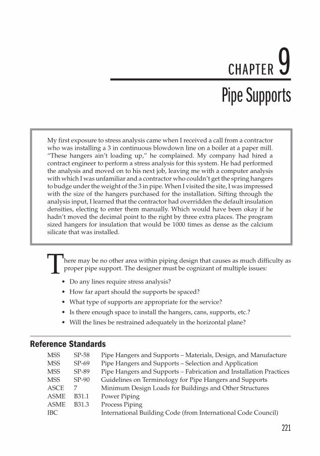
221
CHAPTER 9Pipe Supports
My first exposure to stress analysis came when I received a call from a contractor who was installing a 3 in continuous blowdown line on a boiler at a paper mill. “These hangers ain’t loading up,” he complained. My company had hired a contract engineer to perform a stress analysis for this system. He had performed the analysis and moved on to his next job, leaving me with a computer analysis with which I was unfamiliar and a contractor who couldn’t get the spring hangers to budge under the weight of the 3 in pipe. When I visited the site, I was impressed with the size of the hangers purchased for the installation. Sifting through the analysis input, I learned that the contractor had overridden the default insulation densities, electing to enter them manually. Which would have been okay if he hadn’t moved the decimal point to the right by three extra places. The program sized hangers for insulation that would be 1000 times as dense as the calcium silicate that was installed.
here may be no other area within piping design that causes as much difficulty as proper pipe support. The designer must be cognizant of multiple issues:
• Do any lines require stress analysis ?
• How far apart should the supports be spaced?
• What type of supports are appropriate for the service?
• Is there enough space to install the hangers, cans, supports, etc.?
• Will the lines be restrained adequately in the horizontal plane?
Reference StandardsMSS SP-58 Pipe Hangers and Supports – Materials, Design, and ManufactureMSS SP-69 Pipe Hangers and Supports – Selection and ApplicationMSS SP-89 Pipe Hangers and Supports – Fabrication and Installation PracticesMSS SP-90 Guidelines on Terminology for Pipe Hangers and SupportsASCE 7 Minimum Design Loads for Buildings and Other StructuresASME B31.1 Power PipingASME B31.3 Process PipingIBC International Building Code (from International Code Council)
T
222 C h a p t e r 9
Pipe RoutingsA “rookie” mistake is to lay out a pipe route without regard for how it is to be supported. Piping is rarely self-supporting. Provisions must almost always be made for supporting piping in order to keep loads off of equipment flanges or to prevent excessive sagging in the pipe that at worst interferes with drainage and at best looks bad.
If pipe racks are not available, the designer must look for overhead steel1 or walls with which to support the lines. Of course looking for steel is not always enough. The steel must be adequate to support the static and dynamic loads that may be imposed by the piping.
On a new project this steel may be provided in the form of pipe racks. These racks are specially designed to support the piping and the expected loads need to be conveyed to the structural engineer early in the project. On an existing installation, where a new line is to be run, the steel must often be checked to ensure that it is able to support the additional loads. In a world filled with “pre-engineered buildings,” the ability of the structure to handle additional piping loads is not a foregone conclusion. Pre-engineered buildings with tapered columns, purlins, and bar joists are designed to be economical by minimizing the amount of steel required for the anticipated design conditions. Once the clever structural engineer accounts for wind loads, snow loads, dead and live loads, there is often very little left for piping. The piping designer must then often post up from the floor to prevent overstressing the structure.
Common sense dictates that larger or heavier pipes be located closest to the vertical supports holding them. Lighter loads can be placed toward the center of a horizontal support. See Figure 9.1.
Support ConsiderationsLines supported by rods from above will be more flexible than lines supported by shoes from below. Rods can pivot about their attachment point, and so they are not the best choice for lines that are not otherwise restrained horizontally. Struts or snubbers may be required to prevent the pipes from moving excessively in the horizontal plane. Pipe
1 “Steel” in this sense refers to structural steel. Any other structure besides structural steel may be used if it is adequate for the loads imposed by the piping, but structural steel is the most common in industrial settings.
FIGURE 9.1 A trapeze support. Note smaller lines in center, heavier lines near vertical supports.

P i p e S u p p o r t s 223
supported from below can take advantage of the friction between the pipe and the support (if it is rigid enough) to limit horizontal movement.
Degrees-of-Freedom Consider the pipe segment shown in Figure 9.2. The axis of the centerline lies along the Z-axis, the vertical direction lies along the Y-axis, and the direction transverse to the pipe centerline and in the horizontal plane is the X-axis. Each of these axes can also be used to describe rotational parameters by applying the right-hand rule2 around the axis.
This convention can be used to describe displacements, forces, and moments. Because we have three linear axes and three rotational axes, we have six degrees-of-freedom (DOF). An unrestrained point on a pipe floating in space would have six DOF. We selectively remove some of these DOFs when we apply restraints or supports to the pipe.
A simple pipe support is shown in Figure 9.3. We lay the pipe across a piece of supporting steel and rely on gravity to hold it in place. The steel provides a vertical restraint, and since the pipe is free to move in the positive vertical direction (up), if a force so acted upon it, we say that this support is a +Y restraint.
Perhaps we don’t want the pipe to ever lift off of the supporting steel. We can install a U-bolt to secure it as shown in Figure 9.4. This is a Y-restraint, but on closer inspection, we can argue that since the U-bolt traps the pipe in the transverse direction, there is also an X restraint. Further, if the nuts are very tight, there may also be an axial restraint acting along the Z-axis. This Z-axis restraint is provided only at two points—the 12 and 6 o’clock positions of the pipe. This is not much to hold the pipe in the axial direction, and it relies entirely on the friction force produced by the tightening of the nuts. Still, if the supporting steel is stiff in the axial direction and if the nuts are tight, we can say that the pipe is restrained axially.
2 Place your right thumb in the direction of the axis, and make a fist. The rotational parameter is oriented in the same direction as your fingers.
FIGURE 9.2 Pipe support orientation.
FIGURE 9.3 Single restraint, 5 DOF.
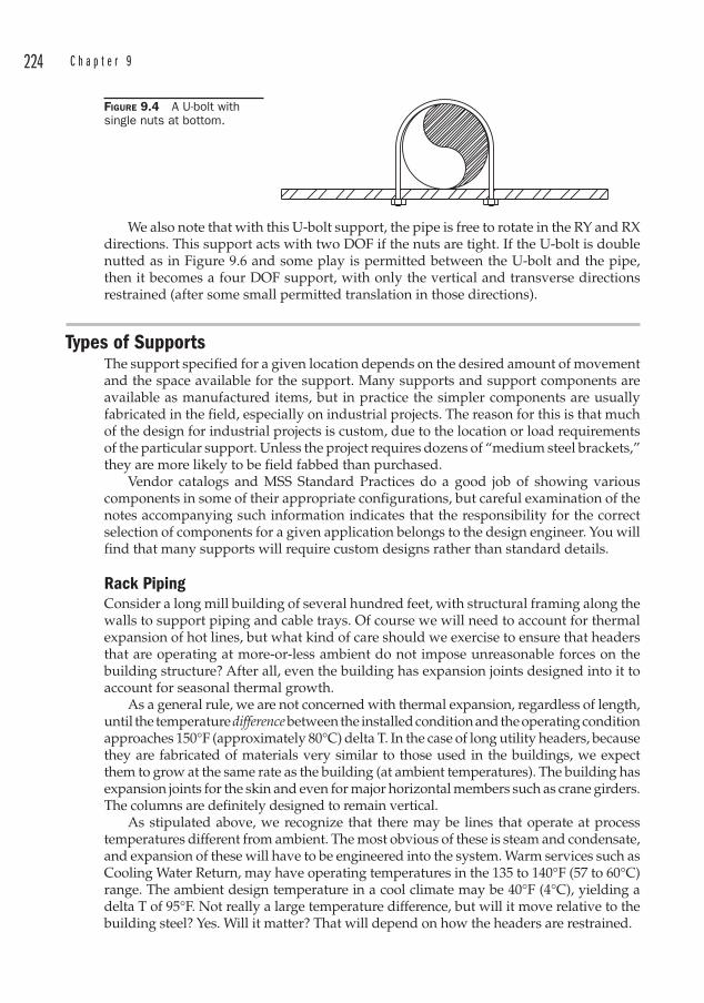
224 C h a p t e r 9
We also note that with this U-bolt support, the pipe is free to rotate in the RY and RX directions. This support acts with two DOF if the nuts are tight. If the U-bolt is double nutted as in Figure 9.6 and some play is permitted between the U-bolt and the pipe, then it becomes a four DOF support, with only the vertical and transverse directions restrained (after some small permitted translation in those directions).
Types of SupportsThe support specified for a given location depends on the desired amount of movement and the space available for the support. Many supports and support components are available as manufactured items, but in practice the simpler components are usually fabricated in the field, especially on industrial projects. The reason for this is that much of the design for industrial projects is custom, due to the location or load requirements of the particular support. Unless the project requires dozens of “medium steel brackets,” they are more likely to be field fabbed than purchased.
Vendor catalogs and MSS Standard Practices do a good job of showing various components in some of their appropriate configurations, but careful examination of the notes accompanying such information indicates that the responsibility for the correct selection of components for a given application belongs to the design engineer. You will find that many supports will require custom designs rather than standard details.
Rack Piping Consider a long mill building of several hundred feet, with structural framing along the walls to support piping and cable trays. Of course we will need to account for thermal expansion of hot lines, but what kind of care should we exercise to ensure that headers that are operating at more-or-less ambient do not impose unreasonable forces on the building structure? After all, even the building has expansion joints designed into it to account for seasonal thermal growth.
As a general rule, we are not concerned with thermal expansion , regardless of length, until the temperature difference between the installed condition and the operating condition approaches 150°F (approximately 80°C) delta T. In the case of long utility headers , because they are fabricated of materials very similar to those used in the buildings, we expect them to grow at the same rate as the building (at ambient temperatures). The building has expansion joints for the skin and even for major horizontal members such as crane girders. The columns are definitely designed to remain vertical.
As stipulated above, we recognize that there may be lines that operate at process temperatures different from ambient. The most obvious of these is steam and condensate, and expansion of these will have to be engineered into the system. Warm services such as Cooling Water Return, may have operating temperatures in the 135 to 140°F (57 to 60°C) range. The ambient design temperature in a cool climate may be 40°F (4°C), yielding a delta T of 95°F. Not really a large temperature difference, but will it move relative to the building steel? Yes. Will it matter? That will depend on how the headers are restrained.
FIGURE 9.4 A U-bolt with single nuts at bottom.
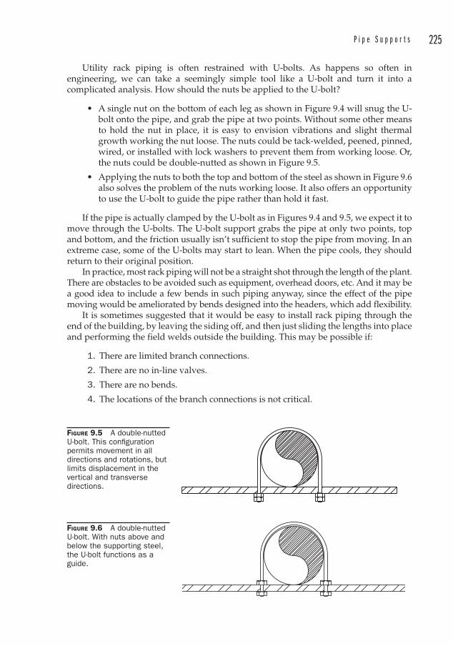
P i p e S u p p o r t s 225
Utility rack piping is often restrained with U-bolts . As happens so often in engineering, we can take a seemingly simple tool like a U-bolt and turn it into a complicated analysis. How should the nuts be applied to the U-bolt?
• A single nut on the bottom of each leg as shown in Figure 9.4 will snug the U-bolt onto the pipe, and grab the pipe at two points. Without some other means to hold the nut in place, it is easy to envision vibrations and slight thermal growth working the nut loose. The nuts could be tack-welded, peened, pinned, wired, or installed with lock washers to prevent them from working loose. Or, the nuts could be double-nutted as shown in Figure 9.5.
• Applying the nuts to both the top and bottom of the steel as shown in Figure 9.6 also solves the problem of the nuts working loose. It also offers an opportunity to use the U-bolt to guide the pipe rather than hold it fast.
If the pipe is actually clamped by the U-bolt as in Figures 9.4 and 9.5, we expect it to move through the U-bolts . The U-bolt support grabs the pipe at only two points, top and bottom, and the friction usually isn’t sufficient to stop the pipe from moving. In an extreme case, some of the U-bolts may start to lean. When the pipe cools, they should return to their original position.
In practice, most rack piping will not be a straight shot through the length of the plant. There are obstacles to be avoided such as equipment, overhead doors, etc. And it may be a good idea to include a few bends in such piping anyway, since the effect of the pipe moving would be ameliorated by bends designed into the headers, which add flexibility.
It is sometimes suggested that it would be easy to install rack piping through the end of the building, by leaving the siding off, and then just sliding the lengths into place and performing the field welds outside the building. This may be possible if:
1. There are limited branch connections.
2. There are no in-line valves.
3. There are no bends.
4. The locations of the branch connections is not critical.
FIGURE 9.5 A double-nutted U-bolt. This confi guration permits movement in all directions and rotations, but limits displacement in the vertical and transverse directions.
FIGURE 9.6 A double-nutted U-bolt. With nuts above and below the supporting steel, the U-bolt functions as a guide.
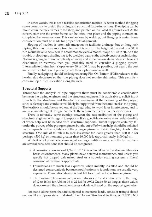
226 C h a p t e r 9
In other words, this is not a feasible construction method. A better method if rigging space permits is to prefab the piping and structural frame in sections. The piping can be mounted in the rack frames in the shop, and painted or insulated at ground level. At the construction site the entire frame can be lifted into place and the piping connections completed between sections. This can be done by welding, but flanging is easier. Some consideration must be made for proper field alignment.
Sloping of headers is often advantageous to facilitate drainage, but on long rack piping, this may prove more trouble than it is worth. The height at the end of a 500 ft run would have to be 62.5 in to accommodate even a modest slope of 1/8 in/ft. And the trouble in sloping such a line has to be weighed against the effectiveness of such sloping. No line is going to drain completely anyway, and if the process demands such levels of cleanliness or recovery, then you probably need to consider a pigging system. Intermediate drains from slopes every 50 or 100 ft may be possible, but again, the cost and constructability will probably rule these options out as well.
Finally, rack piping should be designed using Flat-On-Bottom (FOB) reducers as the header size decreases so that the piping does not require shimming. This permits a constant top of steel elevation along the rack.
Structural SupportsThroughout the analysis of pipe supports there must be considerable coordination between the piping engineer and the structural engineer. It is advisable to solicit input from both the structural and the electrical engineers at the beginning of the project, since cable trays and conduits will likely be supported from the same steel as the piping. The territory should be carved out at the beginning to avoid later interferences, and to arrive at an intelligent design that meets the requirements of all of the disciplines.
There is naturally some overlap between the responsibilities of the piping and structural engineer with regard to supports. It is a good idea to arrive at an understanding of when help will be needed with structural supports. Trivial supports certainly fall under the purvey of the piping engineer, but the cut-off of where help should be solicited really depends on the confidence of the piping engineer in distributing high loads to the structure. One rule-of-thumb is to seek assistance for loads greater than 10,000 lb (or perhaps 4500 kg) or moments greater than 10,000 ft-lb (approximately 1400 kgf-m).
While it is not possible to know what loading conditions may be in the future, there are several considerations that should be recognized:
• A corrosion allowance of 1/16 to 3/16 in is often taken on the steel members for harsh environments. Many plants have deferred maintenance, and unless you specify hot dipped galvanized steel or a superior coating system, a liberal corrosion allowance is appropriate.
• Foundations are much less expensive when initially installed and should be designed conservatively because modifications to foundations are usually very expensive. Foundation design is best left to a qualified structural engineer.
• The maximum tension or compressive stresses in the steel should be in the range of 12 to 16 ksi for A36, or 16 to 22 ksi for A992 Grade 50, as long as these values do not exceed the allowable stresses calculated based on the support geometry.
For stand-alone posts that are subjected to eccentric loads, consider using a closed section, like a pipe or structural steel tube (Hollow Structural Sections , or “HSS ”). Not
P i p e S u p p o r t s 227
only do these sections offer superior resistance to axial torque, they are easier to paint than wide flange beams. A slender wide flange used as a column has very little resistance to torque, and can be deflected significantly under light loads.
Support Spacing
Years ago at a consulting firm we decided to save money by using PVC instead of stainless steel for a deionized water line. Deionized water is not corrosive, but it is something of a solvent in that it is “hungry for ions.” Carbon steel would be a poor choice for DI water since the iron would dissolve.
Unfortunately, the support spacing in the rack piping was too long for the PVC, and when the client complained that the piping sagged, a retrofit with steel channels was made to help support the PVC.
There are many tables available to the engineer with recommendations on the spacing of supports. Some of these are more useful than others. The International Mechanical Code provides a table that merely provides a maximum horizontal spacing without regard for diameter. Clearly such a table is geared toward hydronics and plumbing rather than industrial applications.
ASME B31.1 provides guidelines in Table 121.5 for maximum spacing based on certain typical criteria such as:
• Horizontal pipe runs• Maximum operating temperature of 750°F (400°C)• No concentrated loads such as valves, flanges, specialties (or a vertical run)• Insulated carbon steel pipe with a bending stress not greater than 2300 psi• Standard weight or heavier• Permissible sag is 0.1 in (2.5 mm)
The ASME B31.1 recommended support spans are provided in Table 9.1, along with additional sizes not included the ASME table. In addition to the conditions above, note the following:
1. No consideration is made for seismic conditions. Seismically sensitive areas should always have a stress analysis performed for critical lines.
2. Even though the table groups steam together with air and gas, the prudent designer will consider steam lines to be water-filled. This will certainly be the case for the hydrotest, and substantial water may exist in steam lines during other periods such as start-up.
3. The 0.1 in sag is a very common criterion for support spacings. This is considered to allow adequate drainage, but one must recognize that there will always be some pocketing of liquids in any pipeline installed with normal construction tolerances. Think of the 0.1 in sag as a design guideline, rather than an acceptable limit for drainage.3
3 If wind loads are a serious consideration, a separate analysis may be undertaken to ensure that the natural frequency of the pipe segments is greater than 4 Hz. One source states that if the sag exceeds 5/8 in, the natural frequency may exceed 4 Hz. But normal design practice of 0.1 in sag would eliminate this altogether.
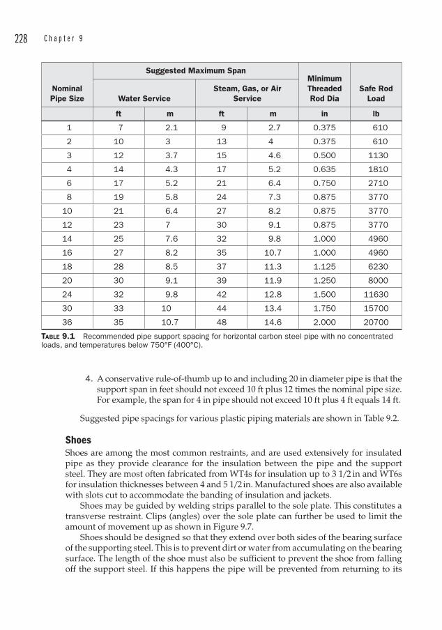
228 C h a p t e r 9
NominalPipe Size
Suggested Maximum SpanMinimumThreadedRod Dia
Safe Rod LoadWater Service
Steam, Gas, or Air Service
ft m ft m in lb
1 7 2.1 9 2.7 0.375 610
2 10 3 13 4 0.375 610
3 12 3.7 15 4.6 0.500 1130
4 14 4.3 17 5.2 0.635 1810
6 17 5.2 21 6.4 0.750 2710
8 19 5.8 24 7.3 0.875 3770
10 21 6.4 27 8.2 0.875 3770
12 23 7 30 9.1 0.875 3770
14 25 7.6 32 9.8 1.000 4960
16 27 8.2 35 10.7 1.000 4960
18 28 8.5 37 11.3 1.125 6230
20 30 9.1 39 11.9 1.250 8000
24 32 9.8 42 12.8 1.500 11630
30 33 10 44 13.4 1.750 15700
36 35 10.7 48 14.6 2.000 20700
TABLE 9.1 Recommended pipe support spacing for horizontal carbon steel pipe with no concentrated loads, and temperatures below 750°F (400°C).
4. A conservative rule-of-thumb up to and including 20 in diameter pipe is that the support span in feet should not exceed 10 ft plus 12 times the nominal pipe size. For example, the span for 4 in pipe should not exceed 10 ft plus 4 ft equals 14 ft.
Suggested pipe spacings for various plastic piping materials are shown in Table 9.2.
ShoesShoes are among the most common restraints, and are used extensively for insulated pipe as they provide clearance for the insulation between the pipe and the support steel. They are most often fabricated from WT4s for insulation up to 3 1/2 in and WT6s for insulation thicknesses between 4 and 5 1/2 in. Manufactured shoes are also available with slots cut to accommodate the banding of insulation and jackets.
Shoes may be guided by welding strips parallel to the sole plate. This constitutes a transverse restraint. Clips (angles) over the sole plate can further be used to limit the amount of movement up as shown in Figure 9.7.
Shoes should be designed so that they extend over both sides of the bearing surface of the supporting steel. This is to prevent dirt or water from accumulating on the bearing surface. The length of the shoe must also be sufficient to prevent the shoe from falling off the support steel. If this happens the pipe will be prevented from returning to its
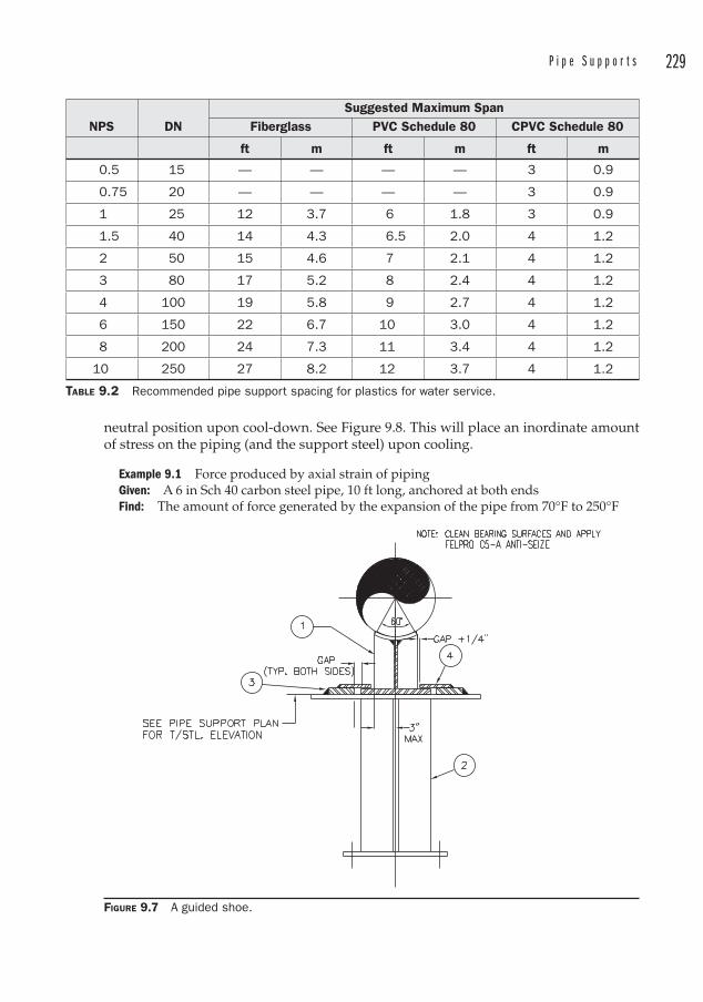
P i p e S u p p o r t s 229
neutral position upon cool-down. See Figure 9.8. This will place an inordinate amount of stress on the piping (and the support steel) upon cooling.
Example 9.1 Force produced by axial strain of pipingGiven: A 6 in Sch 40 carbon steel pipe, 10 ft long, anchored at both endsFind: The amount of force generated by the expansion of the pipe from 70°F to 250°F
NPS DNSuggested Maximum Span
Fiberglass PVC Schedule 80 CPVC Schedule 80
ft m ft m ft m
0.5 15 — — — — 3 0.9
0.75 20 — — — — 3 0.9
1 25 12 3.7 6 1.8 3 0.9
1.5 40 14 4.3 6.5 2.0 4 1.2
2 50 15 4.6 7 2.1 4 1.2
3 80 17 5.2 8 2.4 4 1.2
4 100 19 5.8 9 2.7 4 1.2
6 150 22 6.7 10 3.0 4 1.2
8 200 24 7.3 11 3.4 4 1.2
10 250 27 8.2 12 3.7 4 1.2
TABLE 9.2 Recommended pipe support spacing for plastics for water service.
FIGURE 9.7 A guided shoe.
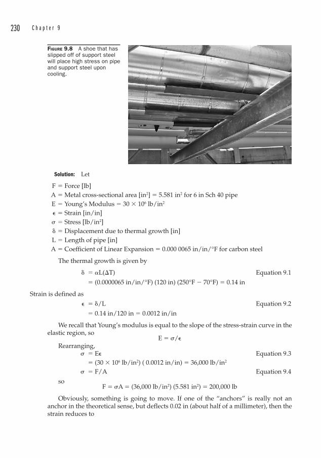
230 C h a p t e r 9
Solution: Let
F � Force [lb] A � Metal cross-sectional area [in2] � 5.581 in2 for 6 in Sch 40 pipe E � Young’s Modulus � 30 � 106 lb/in2
� � Strain [in/in] � � Stress [lb/in2] � Displacement due to thermal growth [in] L � Length of pipe [in] A � Coefficient of Linear Expansion � 0.000 0065 in/in/°F for carbon steel
The thermal growth is given by
� �L(T) Equation 9.1
� (0.0000065 in/in/°F) (120 in) (250°F � 70°F) � 0.14 in
Strain is defined as
� � /L Equation 9.2
� 0.14 in/120 in � 0.0012 in/in
We recall that Young’s modulus is equal to the slope of the stress-strain curve in the elastic region, so
E � �/�Rearranging,
� � E� Equation 9.3 � (30 � 106 lb/in2) ( 0.0012 in/in) � 36,000 lb/in2 � � F/A Equation 9.4
soF � �A � (36,000 lb/in2) (5.581 in2) � 200,000 lb
Obviously, something is going to move. If one of the “anchors” is really not an anchor in the theoretical sense, but deflects 0.02 in (about half of a millimeter), then the strain reduces to
FIGURE 9.8 A shoe that has slipped off of support steel will place high stress on pipe and support steel upon cooling.

P i p e S u p p o r t s 231
� � (0.14 in � 0.02 in)/120 in � 0.001 in/in and
� � E� � (30 � 106 lb/in2) ( 0.001 in/in) � 30,000 lb/in2, yielding
F � �A � (30,000 lb/in2) (5.581 in2) � 167,000 lb, a difference of 33,000 lb due to the movement of one anchor by half of a millimeter.
The forces generated by even moderately-sized pipes at modest temperature changes are tremendous, but even slight deflection of anchors alleviates the strain and subsequent forces.
The engineer must keep in mind that these forces will be transmitted to the supporting steel, which very often is the building steel (which may be supporting heavy equipment, cranes, etc.). If the displacements are large enough, hot piping is certainly capable of stressing steel into the plastic range, and thermal forces must be accounted for in the design.
AnchorsAnchors restrict displacements in all three axes, and rotation in all three axes. The simplest anchor is a double U-bolt as shown in Figure 9.9. For small loads, this may be adequate, but again, one must recognize that a U-bolt will grab the pipe only at the top and bottom. This cannot be considered a rigid connection for anything other than light loads. Other, more rigid anchors will be of welded construction, as illustrated in Figure 9.10. This anchor utilizes a C4x7.25 with the legs welded to a pipe between NPS 4 and 8 in. This provides a very good bearing surface for the pipe, permits an easy weld, and grabs the pipe securely. The C4 can be welded to any convenient (and rigid) structure.
Other more complex anchors are limited only by the imagination of the engineer, or the economics of the project.
Trapezes Trapezes are erected below overhead steel to provide horizontal members on which to support pipes or electrical utilities. The principals of design are similar to rack piping, namely, to locate the larger or heavier lines near the vertical members.
Light duty services may take advantage of a variety of manufactured clamps similar to Figures 9.11 and 9.12 to attach to overhead steel. Medium duty services may use welding lugs similar to Figure 9.13 to attach the vertical members to the overhead steel. Neither of these trapezes will resist horizontal forces however.
FIGURE 9.9 Double U-bolts acting as an anchor.
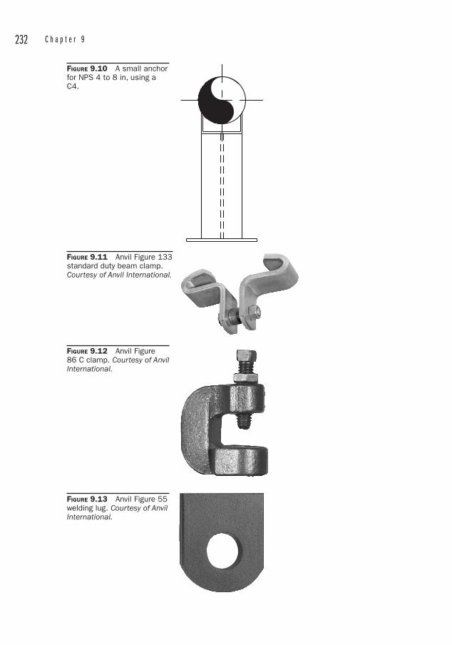
232 C h a p t e r 9
FIGURE 9.10 A small anchor for NPS 4 to 8 in, using a C4.
FIGURE 9.11 Anvil Figure 133 standard duty beam clamp. Courtesy of Anvil International.
FIGURE 9.12 Anvil Figure 86 C clamp. Courtesy of Anvil International.
FIGURE 9.13 Anvil Figure 55 welding lug. Courtesy of Anvil International.
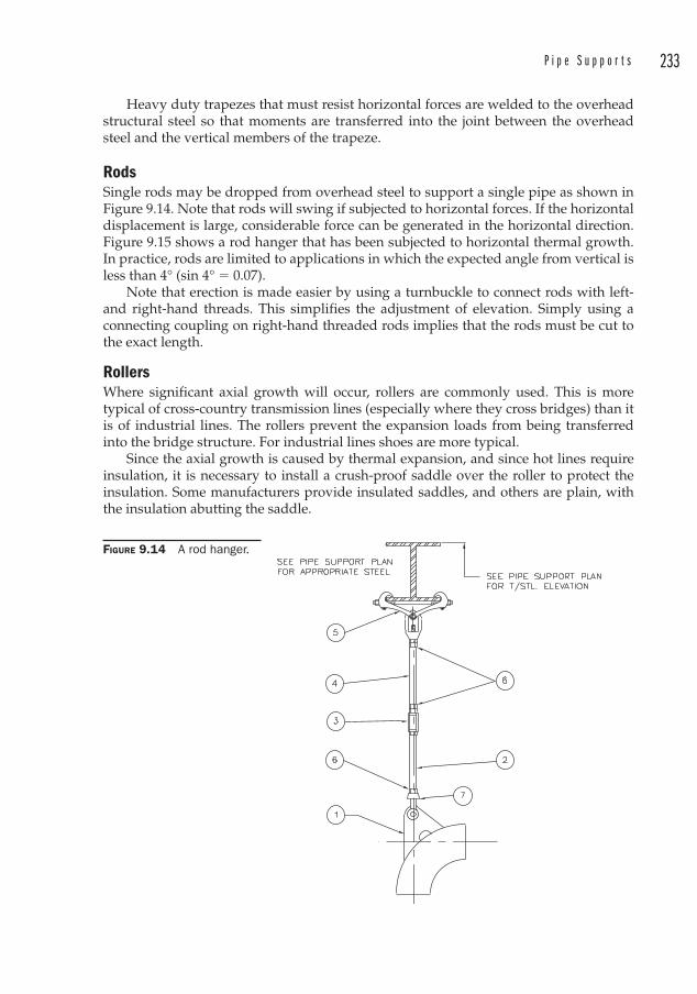
P i p e S u p p o r t s 233
Heavy duty trapezes that must resist horizontal forces are welded to the overhead structural steel so that moments are transferred into the joint between the overhead steel and the vertical members of the trapeze.
RodsSingle rods may be dropped from overhead steel to support a single pipe as shown in Figure 9.14. Note that rods will swing if subjected to horizontal forces. If the horizontal displacement is large, considerable force can be generated in the horizontal direction. Figure 9.15 shows a rod hanger that has been subjected to horizontal thermal growth. In practice, rods are limited to applications in which the expected angle from vertical is less than 4° (sin 4° � 0.07).
Note that erection is made easier by using a turnbuckle to connect rods with left- and right-hand threads. This simplifies the adjustment of elevation. Simply using a connecting coupling on right-hand threaded rods implies that the rods must be cut to the exact length.
RollersWhere significant axial growth will occur, rollers are commonly used. This is more typical of cross-country transmission lines (especially where they cross bridges) than it is of industrial lines. The rollers prevent the expansion loads from being transferred into the bridge structure. For industrial lines shoes are more typical.
Since the axial growth is caused by thermal expansion, and since hot lines require insulation, it is necessary to install a crush-proof saddle over the roller to protect the insulation. Some man u facturers provide insulated saddles, and others are plain, with the insulation abutting the saddle.
FIGURE 9.14 A rod hanger.
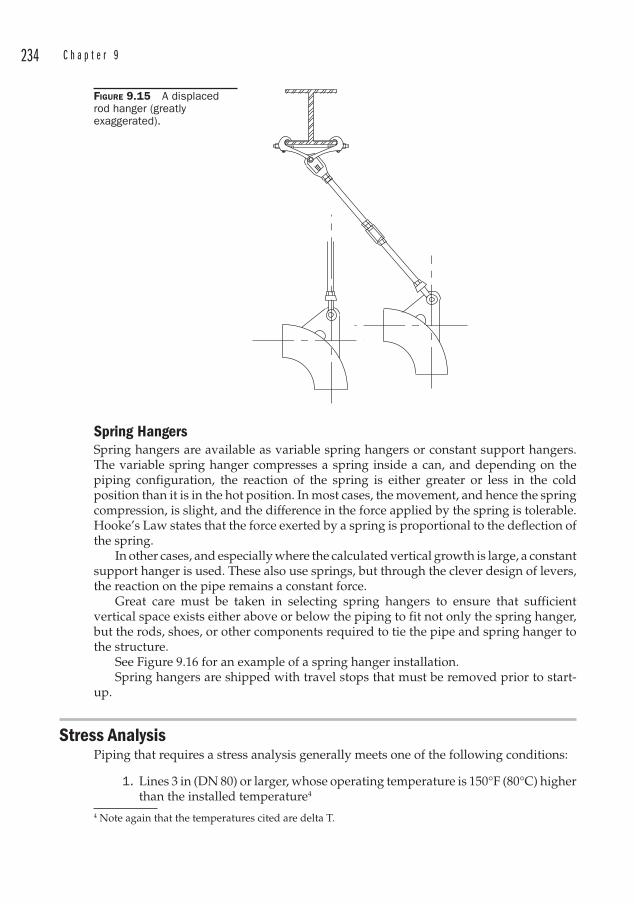
234 C h a p t e r 9
Spring HangersSpring hangers are available as variable spring hangers or constant support hangers. The variable spring hanger compresses a spring inside a can, and depending on the piping configuration, the reaction of the spring is either greater or less in the cold position than it is in the hot position. In most cases, the movement, and hence the spring compression, is slight, and the difference in the force applied by the spring is tolerable. Hooke’s Law states that the force exerted by a spring is proportional to the deflection of the spring.
In other cases, and especially where the calculated vertical growth is large, a constant support hanger is used. These also use springs, but through the clever design of levers, the reaction on the pipe remains a constant force.
Great care must be taken in selecting spring hangers to ensure that sufficient vertical space exists either above or below the piping to fit not only the spring hanger, but the rods, shoes, or other components required to tie the pipe and spring hanger to the structure.
See Figure 9.16 for an example of a spring hanger installation.Spring hangers are shipped with travel stops that must be removed prior to start-
up.
Stress AnalysisPiping that requires a stress analysis generally meets one of the following conditions:
1. Lines 3 in (DN 80) or larger, whose operating temperature is 150°F (80°C) higher than the installed temperature4
4 Note again that the temperatures cited are delta T.
FIGURE 9.15 A displaced rod hanger (greatly exaggerated).
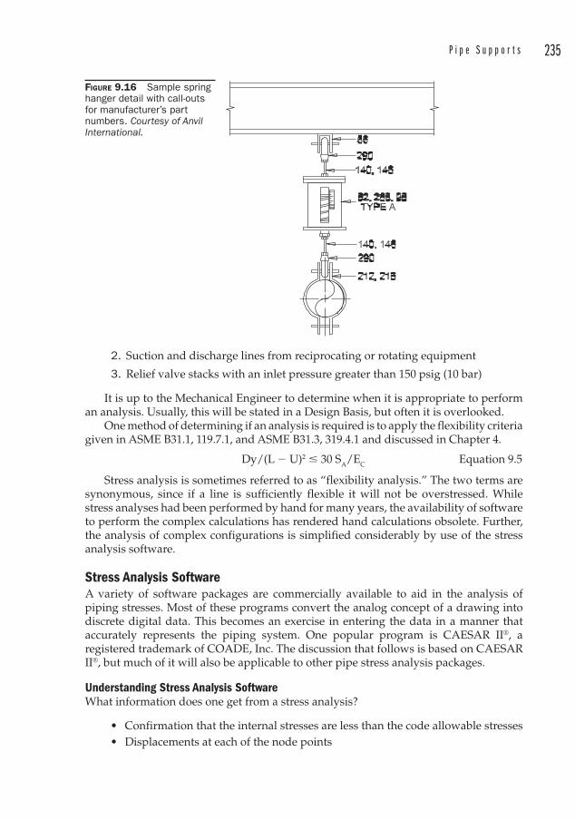
P i p e S u p p o r t s 235
2. Suction and discharge lines from reciprocating or rotating equipment
3. Relief valve stacks with an inlet pressure greater than 150 psig (10 bar)
It is up to the Mechanical Engineer to determine when it is appropriate to perform an analysis. Usually, this will be stated in a Design Basis, but often it is overlooked.
One method of determining if an analysis is required is to apply the flexibility criteria given in ASME B31.1, 119.7.1, and ASME B31.3, 319.4.1 and discussed in Chapter 4.
Dy/(L � U)2 � 30 SA/EC Equation 9.5
Stress analysis is sometimes referred to as “flexibility analysis.” The two terms are synonymous, since if a line is sufficiently flexible it will not be overstressed. While stress analyses had been performed by hand for many years, the availability of software to perform the complex calculations has rendered hand calculations obsolete. Further, the analysis of complex configurations is simplified considerably by use of the stress analysis software.
Stress Analysis SoftwareA variety of software packages are commercially available to aid in the analysis of piping stresses. Most of these programs convert the analog concept of a drawing into discrete digital data. This becomes an exercise in entering the data in a manner that accurately represents the piping system. One popular program is CAESAR II®, a registered trademark of COADE, Inc. The discussion that follows is based on CAESAR II®, but much of it will also be applicable to other pipe stress analysis packages.
Understanding Stress Analysis SoftwareWhat information does one get from a stress analysis?
• Confirmation that the internal stresses are less than the code allowable stresses• Displacements at each of the node points
FIGURE 9.16 Sample spring hanger detail with call-outs for manufacturer’s part numbers. Courtesy of Anvil International.
236 C h a p t e r 9
• Reactions at pipe supports• Specification of spring hangers, if they were modeled in the system
It is important to note that the software does not locate or suggest locations of pipe supports. Nor does it suggest when to use spring hangers. These decisions are left up to the analyst.
The analyst builds a computer model of the pipe system using a set of rules that the software can understand. The software can be very picky about understanding these rules, and this often leads to a lot of time spent debugging the model. The results of the analysis are only as good as the accuracy of the model. The analyst must always exercise good engineering judgment in developing the model, and in interpreting the results.
The software works by breaking the model down into a series of segments. Then it analyzes each segment, considering thermal expansion and beam equations. Any loads are applied as concentrated or uniform loads. These loads include:
• The weight of the pipe itself• The weight of fluid inside the pipe• The weight of any insulation• The weight of flanges or valves• Any uniform applied loads such as snow loads or wind loads• Any concentrated loads• Any dynamic loads such as earthquake loads, relief valve reactions, water
hammer.
Types of AnalysisTwo types of analysis are available through CAESAR II®: static and dynamic. Dynamic analysis includes loads imposed by transient occurrences, such as earthquakes, water hammer, and relief valves firing. Some of these loads, like earthquake loads, can be approximated using static analysis. Others must use dynamic analysis.
A static analysis considers only loads that are applied steadily, such as loads due to thermal expansion or the dead weight of the pipe system.
Load CasesThere are several load cases that must be understood in order to perform a stress analysis. These load cases may appear in static or dynamic analyses.
• The Sustained Case includes dead weight of pipe, fluid, insulation, and pressure of the fluid in the pipe.
• The Occasional Case includes snow, wind, relief valve discharge, and earthquake.
• The Operating Case includes all of the sustained load cases, plus the thermal loads due to pipe expansion.
• The Expansion Case is the algebraic difference between the Operating Case and the Sustained Case
There is no code stress check for the Operating Case for analyses performed under B31.1. Similarly, B31.3 does not process a code stress check for the Operating case under normal circumstances5. If a stress analysis report is prepared for the Operating Case, it
5 ASME B31.3 Appendix P offers alternative rules for flexibility analysis, and a code stress for the Operating Case is possible under those rules.
P i p e S u p p o r t s 237
will yield zeroes for the code stresses or give the user an error message. This is often a source of great confusion for those who read the stress analysis reports. Code stress checks are performed only for the Sustained, Occasional, and Expansion cases. The user should consult the specific pipe code for the analysis to determine which load cases are appropriate for stress checks.
Data EntryBefore the analysis can begin, the following conditions must be met:
• The design must be frozen (no further changes)• The analyst must have all of the design drawings • The analyst must decide on a coordinate system • The analyst must identify the nodes
The coordinate system is a right-hand coordinate system, with +Y always in the “up” direction. +X usually points south, with +Z pointing west. This is a common configuration, but others may be used if they are more convenient. The restraints and the displacements also follow the right-hand rule.
Nodes are what the software uses to identify points in the model. They are always along the centerline of the pipe.
It is up to the analyst to determine where the nodes go and what to call them. Some software has a feature that automatically numbers the nodes, with a user-defined increment. This feature may be used or may be overwritten. The feature does not locate the nodes. If you wanted to model a piece of straight piping that was 20,000 ft long, you could number the first node “10” and the end node “20,” and your job would be done. But you would soon realize that you need to locate all of the supports along the 20,000 ft length.
Nodes should be located wherever something “interesting” is happening to the pipe. “Interesting” means any place where you need to describe a change in the pipe, like a new fitting, or where you want the output to give you information about that point of the pipe. So nodes will be required:
• At every support• At every change in direction• Wherever there is a spec change (material, wall thickness)• Wherever there is a change in the stiffness or loading of the pipe (as at a valve)• Wherever there is a change in the properties of whatever is inside the pipe
(temperature, pressure, density)
It is sometimes convenient to name the nodes according to the pipe size. For instance, the first node of a 6 in diameter line might be 6000, the second node 6010. It is always a good idea to leave 5 or 10 numbers between nodes in case you have to break the segment and add something in between.
Nodes are labeled on the piping drawings. For rigorously documented projects, stress isometrics are prepared. While this produces a very nice document package, it requires the additional step of drawing the iso. It is easier to simply label the nodes on the piping drawings, if that level of documentation can be tolerated.
The software builds an isometric of your piping system using vectors. A graphical representation of the system is available for viewing during the data entry.
238 C h a p t e r 9
One must be very careful to not duplicate any nodes unintentionally. There will be times when you need to make reference to a node that has previously been located. Tees, for example, require that the node at the intersection be specified in three places. But if you unintentionally duplicate a node, expect to spend some time debugging.
Because the data entry process is tedious and requires much precision, you should save your data frequently.
The following items are typical of the various fields that must be entered into the software to fully describe the piping system:
• From and To describe the beginning and ending nodes of the element you are about to describe.
• DX, DY, DZ are direction vectors. These are used to describe the geometry of the element. If the element begins at node 10 and ends at node 20, you have to tell the program how the pipe gets from node 10 to node 20. Note that such entries do not describe thermal growth. They are only lengths in the cold position.
• Diameter is the OD of the pipe.• Weight or Schedule is the schedule of the pipe. • Mill Tolerance is the standard mill tolerance on wall thickness. It is always taken
as 12.5 percent less than the wall thickness unless the tolerance is specified as something else during the purchase of the piping. CAESAR II® uses the mill tolerance to perform a minimum thickness calculation based on the pressure and the piping code, so only the negative value of the mill tolerance is useful to us. (The + mill tolerance is usually disabled). If the pipe wall is not thick enough, CAESAR II® will generate a warning.
• The corrosion allowance is usually specified as 1/16 in, but may be as high as 0.1 in. The CA is generally only active when used in conjunction with ASME B31.3. The B31.3 code requires that CA be accounted for in the Sustained and Occasional load stress calculations only. But the Expansion case may also be enabled to include CA, and this is thought to be more conservative.
Corrosion allowance may also be activated for ASME B31.1 jobs, even though the default is to not consider corrosion allowance in B31.1 stress calculations.
• Insulation thickness • Temperature and pressure can be stated for various operating cases. The
software usually selects an ambient installed temperature of 70°F (21°C) to assess the amount of thermal growth that will occur. The installed temperature must be known, but really only the delta T is crucial to the analysis. The pressure should be entered, but is usually not an important factor unless expansion joints are modeled, or unless the system is a plastic piping system (e.g., FRP). In the case of plastic piping, Bourdon Pressure Effects come into play. This is the phenomenon of internal pressure acting to straighten out a piping system that contains bends. When pipes are bent, the cross section is ovalized. It is thought that the internal pressure tends to distend such a cross section from an oval into a circle. In doing so, the bend tends to “rotate” or open up. Forged fittings or molded FRP elbows have a circular cross section and should not be subject to Bourdon Pressure Effects. Normally, the Bourdon Pressure Effects must be turned OFF, which is the default.
• Bend is used to designate elbows and bends. Certain programs will automatically assign intermediate nodes along the elbow, at the upstream weld line and at the midpoint. The important thing to note is that the TO node ends up at the
P i p e S u p p o r t s 239
downstream weld line of the elbow, although it is always modeled as being at the intersection of the centerlines. There must always be another element following an elbow in order to designate what the orientation of the ell is. Elbow definition is often a primary cause of fatal errors during the run.
• Valves or flanges are known by the generic term “rigids.” Selectable fields permit the user to enter the weight of the rigid element. Valve and flange databases are also available. These invoke a selection of valves and flanges, with various end connections and classes. The length and weight are then automatically entered into the appropriate fields. The user should check the valve values against catalog data to ensure that the database values are accurate.
• Expansion joints may be modeled though their use in steam and condensate lines is generally to be avoided. Some projects, especially those involving gases may require expansion joints that must be modeled.
• Concentric and eccentric reducers are selectable elements. The length must be entered (and an axial offset if the reducer is eccentric), as well as the diameters and wall thicknesses. If your software does not include a database for reducers, Table 7.14 contains average diameters and wall thicknesses that may be used to approximate them.
Additionally, if you are using ASME B31.1, the program will apply a Stress Intensification Factor (SIF) at each end of the reducer. ASME B31.3 is silent regarding SIFs at reducers.
• SIFs for configurations other than elbows and bends are also selectable. Common branch connections may be specified and are calculated internally by the software. Others, including reducers under B31.1 or some flanges under B31.3, must be entered manually. The analyst should refer to Tables D-1 (B31.1) or D300 (B31.3).
Available selections for specifying SIFs include:
1. “Reinforced fabricated tees” are tees such as may be field-fabricated. In this case, a “fish mouth” is cut on the end of the branch pipe and the opening is traced onto the header and cut out. The branch is welded to the header, and a curved reinforcing pad is placed around the branch, and welded to the header. Reinforcing pads are always welded to the header; not to the branch.
2. “Unreinforced fabricated tees” are identical to the reinforced fabricated tee, except that the repad is omitted.
3. “Welding tees” are ASME B16.9 fittings. 4. “Sweepolet®” is a Bonney Forge trademark. These are referred to as contoured,
integrally reinforced, butt-weld branch connections by the piping codes, with low stress intensification factors for low stresses and long fatigue life. The user should note that there may be a different SIF if using a manufacturer other than Bonney Forge.
5. “Weldolet®” is also a Bonney Forge trademark. These area butt-weld branch connections, designed to minimize stress concentrations and provide integral reinforcement.
6. “Extruded welding tees” are special fittings made by pulling a die through the wall of a pipe. These tees match the requirements set forth in the piping codes (see ASME B31.1, 104.3.1(G), or ASME B31.3, 304.3.4(a)). These tees are prevalent in the power industry.
240 C h a p t e r 9
7. “Butt-weld” is not a tee at all, but rather gives the analyst an opportunity to determine the SIF at a girth butt weld, which normally has an SIF of 1.0, which means we don’t worry about it. However, if there is a dramatic change in the wall thickness at a point, then you could specify it here.
8. “Socket weld” is a socket weld fitting. Because socket welds are almost exclusively used on small bore lines, and because small bore lines do not usually require analysis, the SIF is rarely required to be specified at socket welds.
9. “Tapered transition” is not a tee either, but is another way to examine SIFs at adjoining pipes with different wall thicknesses.
10. “Threaded” is not a tee either. According to ASME B31.1 and B31.3, the SIF at threaded fittings is always 2.3. This is rarely encountered in normal industrial stress analyses.
11. “Double welded” pertains to double-welded slip on flanges. ASME B31.3 assigns an SIF of 1.2.
12. “Lap joint flanges” with ASME B16.9 LJ stubs are assigned an SIF of 1.6 by ASME B31.3.
13. “Latrolet®” is another Bonney Forge fitting used for 45° lateral connections. It is available as a butt-weld, 3000# or 6000# classes for socket weld, and threaded applications.
14. “Bonney Forge Insert Weldolet®” is another contoured butt-weld branch connection used in less critical applications. Like the Sweepolet, the attachment welds are easily examined by radiography, ultrasound, and other standard non-destructive techniques. The user should note that there may be a different SIF if using a manufacturer other than Bonney Forge.
15. “Full encirclement tees” are special tees applicable only for the IGE/TD-12 Code.
It is important to note that some configurations are not addressed specifically in the piping codes. One such arrangement is a fabricated cross. Because the codes are silent regarding fabricated crosses, the stress analysis software does not address these either. An attempt may be made to model the cross as two tees, with the intersections sharing a common node. But the result will likely be a warning that indicates that the user has attempted to frame four pipes into a common node. The SIFs will be ignored, yielding a lower stress than required. In cases like this, a Finite Element Analysis (FEA) should be run to determine the actual SIF . This value may then be plugged into the stress analysis software to determine the true stresses. Figure 9.17 illustrates the FEA wireframe model for a cross.
• Restraints are for anchors, supports, guides, and so on. This is probably the most critical area of the data entry because the user must not only determine where the restraints will go (which nodes will be restrained), but also how the restraint will act.
1. “Anchors” are fixed restraints that permit no movement at all. This means no translational movement and no rotational movement.
2. “X, Y, Z” are translational restraints acting along the axis named. If there is no sign preceding the letter, the restraint acts in both directions. If there is a “+” or
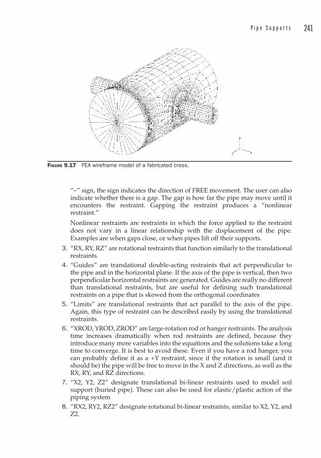
P i p e S u p p o r t s 241
“–” sign, the sign indicates the direction of FREE movement. The user can also indicate whether there is a gap. The gap is how far the pipe may move until it encounters the restraint. Gapping the restraint produces a “nonlinear restraint.”
Nonlinear restraints are restraints in which the force applied to the restraint does not vary in a linear relationship with the displacement of the pipe. Examples are when gaps close, or when pipes lift off their supports.
3. “RX, RY, RZ” are rotational restraints that function similarly to the translational restraints.
4. “Guides” are translational double-acting restraints that act perpendicular to the pipe and in the horizontal plane. If the axis of the pipe is vertical, then twoperpendicular horizontal restraints are generated. Guides are really no different than translational restraints, but are useful for defining such translational restraints on a pipe that is skewed from the orthogonal coordinates
5. “Limits” are translational restraints that act parallel to the axis of the pipe.Again, this type of restraint can be described easily by using the translational restraints.
6. “XROD, YROD, ZROD” are large-rotation rod or hanger restraints. The analysis time increases dramatically when rod restraints are defined, because they introduce many more variables into the equations and the solutions take a long time to converge. It is best to avoid these. Even if you have a rod hanger, you can probably define it as a +Y restraint, since if the rotation is small (and it should be) the pipe will be free to move in the X and Z directions, as well as the RX, RY, and RZ directions.
7. “X2, Y2, Z2” designate translational bi-linear restraints used to model soil support (buried pipe). These can also be used for elastic/plastic action of the piping system
8. “RX2, RY2, RZ2” designate rotational bi-linear restraints, similar to X2, Y2, and Z2.
FIGURE 9.17 FEA wireframe model of a fabricated cross.
242 C h a p t e r 9
9. “XSPR, YSPR, ZSPR” designate “bottom out” springs, and occur infrequently in analysis.
10. “XSNB, YSNB, ZSNB” designate translational snubbers , and again are not often encountered in general industry. They are used where displacements due to occasional loads must be controlled.
• “Hangers” specifically means spring hangers.
• If the element you are defining begins or ends at a vessel or tank, you can introduce nozzle flexibility into the model. Nozzles are often modeled as anchors. Allowing for nozzle flexibility often helps in reducing the calculated loads on nozzles. This is important if you are faced with an allowable nozzle load on a tank or vessel. Modeling the nozzle as an anchor is more conservative, but not necessarily more accurate.
• Displacements define any initial displacements, such as may occur when defining a tie-point to an already hot system.
• Forces and moments define any initial forces or moments. These values must usually be calculated. Forces and moments may also be used to model the weight of a valve operator, or occasional maintenance loads.
• Uniform loads may be used to define a load beyond the weight of the pipe, fluid, and insulation. This may be a dust load inside a large-diameter duct, a snow load, or perhaps a walkway mounted off of a large diameter duct. The uniform loads are described by vectors that act along the centerline of the pipe.
Uniform loads may also be used to calculate seismic reactions in a static analysis. You could perform a dynamic analysis to determine seismic reactions, but this is a complex analysis. Adequate results can often be achieved by simulating the seismic loads imposed on a piping system in the static analysis. In this case, a factor is applied to the weight of the system, and this weight is then applied as a uniform load to the system in one of the horizontal directions. The factors can be derived from procedures provided in the ASCE 7 “Minimum Design Loads for Buildings and Other Structures.”
The interested reader is referred to ASME B31E “Standard for the Seismic Design and Retrofit of Above-Ground Piping Systems” and The American Lifelines Alliance “Seismic Design and Retrofit of Piping Systems”6. The American Lifelines document offers an excellent treatment of seismic analysis.
• Wind loads on piping exposed to wind may be modeled by including a Wind Shape Factor from ASCE 7. Another way of handling the wind load is to calculate it by hand and apply it to the piping as a horizontal uniform load.
• Material properties are used to establish the allowable stress for the piping material. Cold and hot allowable stresses are either entered from the code appendices or selected from a database of common materials. The hot allowable stress entered must correspond to the operating temperatures entered earlier. Selecting the material also automatically fills in the values for Elastic Modulus, Poisson’s Ratio, and pipe density.
6 http://www.americanlifelinesalliance.org/pdf/Seismic_Design_and_Retrofit_of_Piping_Systems.pdf
P i p e S u p p o r t s 243
• Longitudinal weld joint efficiency is usually 1.0 but may be as low as 0.60 for furnace butt-welded pipe.
• Fluid density is usually entered in units of lb/in3 (kg/m3), or in terms of the Specific Gravity of the fluid.
• Insulation densities are available as default values (usually taken to be calcium silicate) through a material database, or may be entered manually. If you manually enter a value, be certain that the value is correct. This is one place where missing a decimal point can have a DRAMATIC impact on the results.
An unfortunate tendency of many who use computer programs is to place too much faith in the results, simply because the output is a neatly organized report, with results out to 4 decimal places. Users of such programs must constantly be aware that the results are only as good as the input. In the case of CAESAR II®, the input may be checked in a variety of ways. A graphic isometric may be manipulated to provide views from virtually any angle. Input data may be reviewed in a spreadsheet format to check for consistency among the various elements and properties. And while errors will prevent a job from being run, the warnings and notes are also important and will be reviewed by the prudent analyst.
These tasks should be ongoing through the data entry process. The model must be checked for accuracy before any results are examined.
Interpreting the ResultsThe first thing an analyst does after checking the accuracy of the model and completing a stress run is to check if the Sustained, Occasional, and Expansion load cases passed the code stress checks. Even if they have passed, that is not the end of the story. The displacements and the loads at the restraints must also be checked to make sure that the results are reasonable. Large displacements may indicate that some data entry is incorrect, or that the pipe is insufficiently restrained. High loads or moments on the restraints may indicate that the pipe is not sufficiently flexible or is overly restrained.
Very often the stress checks fail in some area. In those cases, the analyst must dig deeper. A good place to start is with the piping geometry to make sure that the input is correct. Graphic representations or animations are useful for spot checking this. Checking the restraint reports is also very useful. If a restraint is showing zero load in the operating case near an overstressed node, this indicates that the pipe is rising off the support. This may be a good candidate for a spring hanger. Remember that the software does not locate supports or recommend hangers; that is left to the analyst.
Also look for restraints with no or very low loads. These can often be eliminated, resulting in a cost savings.

This page intentionally left blank

245
CHAPTER 10Drafting Practice
Engineering curricula are not usually loaded with practical information. If a current engineering program even offers engineering graphics, it is often biased toward learning CAD rather than in the clear presentation of information on a sheet of bond.
I once had a junior engineer working for me who was billed as good at producing CAD drawings, which made me feel inadequate because at the time I had not yet learned any of the CAD programs.
Not long afterward, I was reviewing a piping drawing by the engineer. He had located a pump baseplate spanning between two columns of a pipe bridge. Worse yet, he called out the baseplate as checker plate, and none of the valving was accessible from platforms.
The Purpose of Piping DrawingsIt might be advisable to remind ourselves what the purpose of a piping drawing is. Like other engineering drawings, piping drawings have multiple purposes, depending on who is using them. If a contractor could be relied upon to build a system or building to satisfy the customer’s requirements and to comply with the applicable codes, one could argue that drawings are not necessary at all. Except for “field-routed ” piping, the Owner could simply turn the contractor loose and get the finished product. Obviously, for anything but the simplest project, planning is required to ensure that all of the systems operate as they should, and everything fits together with no interferences.
The Contractor The contractor relies on the piping drawings to explain how the piping and equipment must be installed. This will ensure that everything “fits” (no interferences), and that there are adequate maintenance and operational clearances, which may not otherwise be obvious to an installer.
The contractor must also determine what material is required to be furnished so that he can order the appropriate quantities and types of materials for the project. The “shopping list” that he prepares is called a Material Take-Off (MTO).
Further, the prospective contractor will review the drawings during the bid phase, so that he can submit a competitive bid for the project. In that case, he will need to understand the scope of work so that he can estimate his material costs (developed from the MTO) as well as the manpower required to erect the system in the schedule set forth by the Owner.
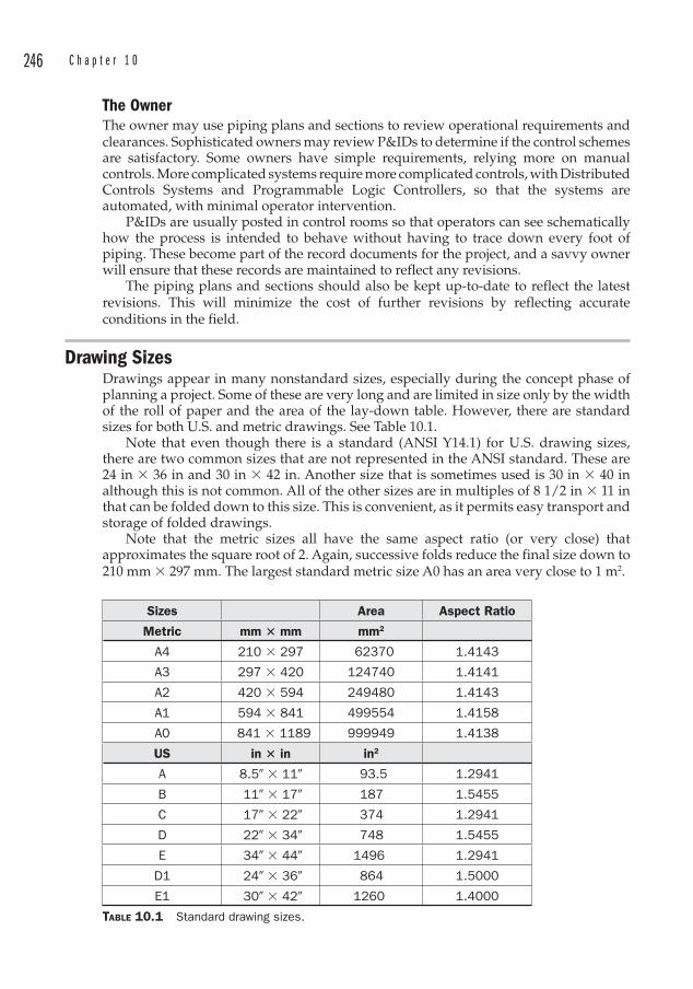
246 C h a p t e r 1 0
The OwnerThe owner may use piping plans and sections to review operational requirements and clearances. Sophisticated owners may review P&IDs to determine if the control schemes are satisfactory. Some owners have simple requirements, relying more on manual controls. More complicated systems require more complicated controls, with Distributed Controls Systems and Programmable Logic Controllers, so that the systems are automated, with minimal operator intervention.
P&IDs are usually posted in control rooms so that operators can see schematically how the process is intended to behave without having to trace down every foot of piping. These become part of the record documents for the project, and a savvy owner will ensure that these records are maintained to reflect any revisions.
The piping plans and sections should also be kept up-to-date to reflect the latest revisions. This will minimize the cost of further revisions by reflecting accurate conditions in the field.
Drawing Sizes Drawings appear in many nonstandard sizes, especially during the concept phase of planning a project. Some of these are very long and are limited in size only by the width of the roll of paper and the area of the lay-down table. However, there are standard sizes for both U.S. and metric drawings. See Table 10.1.
Note that even though there is a standard (ANSI Y14.1) for U.S. drawing sizes, there are two common sizes that are not represented in the ANSI standard. These are 24 in � 36 in and 30 in � 42 in. Another size that is sometimes used is 30 in � 40 in although this is not common. All of the other sizes are in multiples of 8 1/2 in � 11 in that can be folded down to this size. This is convenient, as it permits easy transport and storage of folded drawings.
Note that the metric sizes all have the same aspect ratio (or very close) that approximates the square root of 2. Again, successive folds reduce the final size down to 210 mm � 297 mm. The largest standard metric size A0 has an area very close to 1 m2.
Sizes Area Aspect Ratio
Metric mm � mm mm2
A4 210 � 297 62370 1.4143
A3 297 � 420 124740 1.4141
A2 420 � 594 249480 1.4143
A1 594 � 841 499554 1.4158
A0 841 � 1189 999949 1.4138
US in � in in2
A 8.5� � 11� 93.5 1.2941
B 11� � 17� 187 1.5455
C 17� � 22� 374 1.2941
D 22� � 34� 748 1.5455
E 34� � 44� 1496 1.2941
D1 24� � 36� 864 1.5000
E1 30� � 42� 1260 1.4000
TABLE 10.1 Standard drawing sizes.
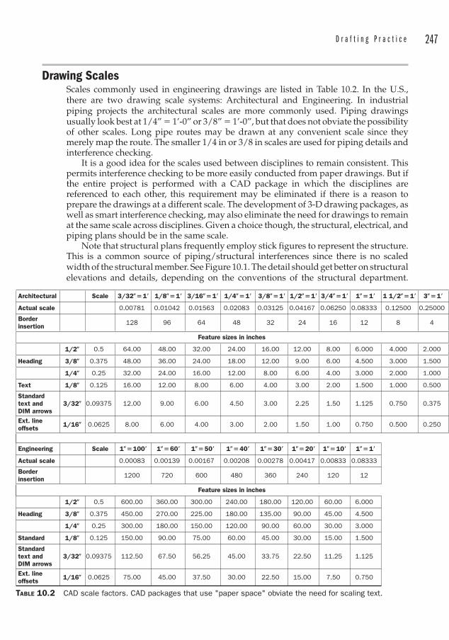
D r a f t i n g P r a c t i c e 247
Drawing Scales Scales commonly used in engineering drawings are listed in Table 10.2. In the U.S., there are two drawing scale systems: Architectural and Engineering. In industrial piping projects the architectural scales are more commonly used. Piping drawings usually look best at 1/4” � 1’-0” or 3/8” � 1’-0”, but that does not obviate the possibility of other scales. Long pipe routes may be drawn at any convenient scale since they merely map the route. The smaller 1/4 in or 3/8 in scales are used for piping details and interference checking.
It is a good idea for the scales used between disciplines to remain consistent. This permits interference checking to be more easily conducted from paper drawings. But if the entire project is performed with a CAD package in which the disciplines are referenced to each other, this requirement may be eliminated if there is a reason to prepare the drawings at a different scale. The development of 3-D drawing packages, as well as smart interference checking, may also eliminate the need for drawings to remain at the same scale across disciplines. Given a choice though, the structural, electrical, and piping plans should be in the same scale.
Note that structural plans frequently employ stick figures to represent the structure. This is a common source of piping/structural interferences since there is no scaled width of the structural member. See Figure 10.1. The detail should get better on structural elevations and details, depending on the conventions of the structural department.
Architectural Scale 3/32�� 1� 1/8�� 1� 3/16�� 1� 1/4�� 1� 3/8�� 1� 1/2�� 1� 3/4�� 1� 1�� 1� 1 1/2�� 1� 3�� 1�
Actual scale 0.00781 0.01042 0.01563 0.02083 0.03125 0.04167 0.06250 0.08333 0.12500 0.25000
Borderinsertion 128 96 64 48 32 24 16 12 8 4
Feature sizes in inches
1/2� 0.5 64.00 48.00 32.00 24.00 16.00 12.00 8.00 6.000 4.000 2.000
Heading 3/8� 0.375 48.00 36.00 24.00 18.00 12.00 9.00 6.00 4.500 3.000 1.500
1/4� 0.25 32.00 24.00 16.00 12.00 8.00 6.00 4.00 3.000 2.000 1.000
Text 1/8� 0.125 16.00 12.00 8.00 6.00 4.00 3.00 2.00 1.500 1.000 0.500
Standardtext and DIM arrows
3/32� 0.09375 12.00 9.00 6.00 4.50 3.00 2.25 1.50 1.125 0.750 0.375
Ext. line offsets 1/16� 0.0625 8.00 6.00 4.00 3.00 2.00 1.50 1.00 0.750 0.500 0.250
Engineering Scale 1�� 100� 1�� 60� 1�� 50� 1�� 40� 1�� 30� 1�� 20� 1�� 10� 1�� 1�
Actual scale 0.00083 0.00139 0.00167 0.00208 0.00278 0.00417 0.00833 0.08333
Borderinsertion 1200 720 600 480 360 240 120 12
Feature sizes in inches
1/2� 0.5 600.00 360.00 300.00 240.00 180.00 120.00 60.00 6.000
Heading 3/8� 0.375 450.00 270.00 225.00 180.00 135.00 90.00 45.00 4.500
1/4� 0.25 300.00 180.00 150.00 120.00 90.00 60.00 30.00 3.000
Standard 1/8� 0.125 150.00 90.00 75.00 60.00 45.00 30.00 15.00 1.500
Standardtext and DIM arrows
3/32� 0.09375 112.50 67.50 56.25 45.00 33.75 22.50 11.25 1.125
Ext. line offsets 1/16� 0.0625 75.00 45.00 37.50 30.00 22.50 15.00 7.50 0.750
TABLE 10.2 CAD scale factors. CAD packages that use "paper space" obviate the need for scaling text.
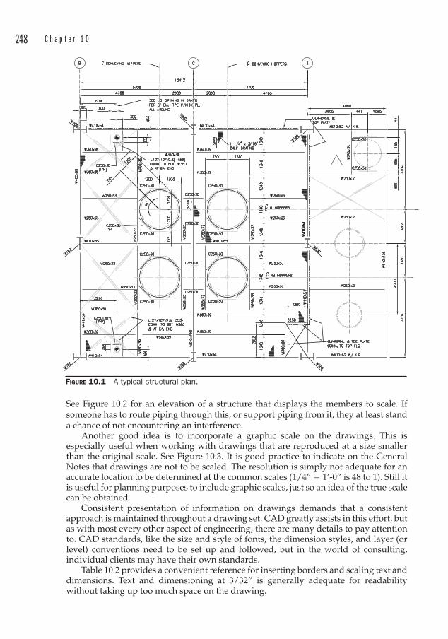
248 C h a p t e r 1 0
See Figure 10.2 for an elevation of a structure that displays the members to scale. If someone has to route piping through this, or support piping from it, they at least stand a chance of not encountering an interference.
Another good idea is to incorporate a graphic scale on the drawings. This is especially useful when working with drawings that are reproduced at a size smaller than the original scale. See Figure 10.3. It is good practice to indicate on the General Notes that drawings are not to be scaled. The resolution is simply not adequate for an accurate location to be determined at the common scales (1/4” � 1’-0” is 48 to 1). Still it is useful for planning purposes to include graphic scales, just so an idea of the true scale can be obtained.
Consistent presentation of information on drawings demands that a consistent approach is maintained throughout a drawing set. CAD greatly assists in this effort, but as with most every other aspect of engineering, there are many details to pay attention to. CAD standards, like the size and style of fonts, the dimension styles, and layer (or level) conventions need to be set up and followed, but in the world of consulting, individual clients may have their own standards.
Table 10.2 provides a convenient reference for inserting borders and scaling text and dimensions. Text and dimensioning at 3/32” is generally adequate for readability without taking up too much space on the drawing.
FIGURE 10.1 A typical structural plan.
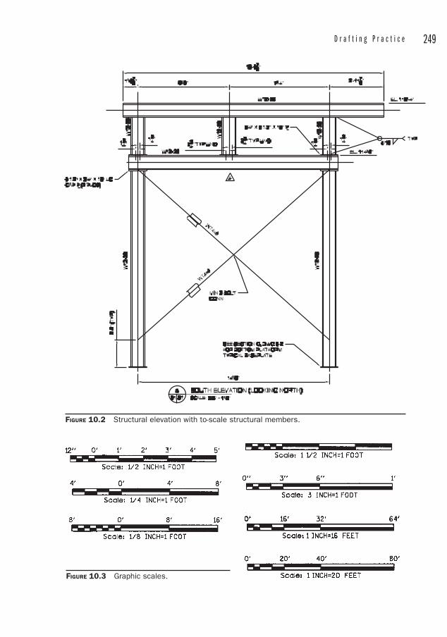
D r a f t i n g P r a c t i c e 249
FIGURE 10.2 Structural elevation with to-scale structural members.
FIGURE 10.3 Graphic scales.
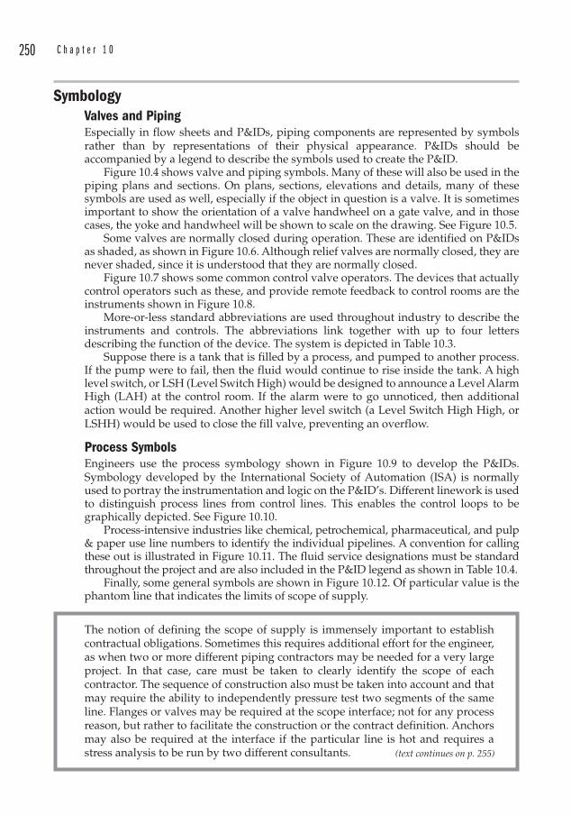
250 C h a p t e r 1 0
SymbologyValves and Piping Especially in flow sheets and P&IDs, piping components are represented by symbols rather than by representations of their physical appearance. P&IDs should be accompanied by a legend to describe the symbols used to create the P&ID.
Figure 10.4 shows valve and piping symbols. Many of these will also be used in the piping plans and sections. On plans, sections, elevations and details, many of these symbols are used as well, especially if the object in question is a valve. It is sometimes important to show the orientation of a valve handwheel on a gate valve, and in those cases, the yoke and handwheel will be shown to scale on the drawing. See Figure 10.5.
Some valves are normally closed during operation. These are identified on P&IDs as shaded, as shown in Figure 10.6. Although relief valves are normally closed, they are never shaded, since it is understood that they are normally closed.
Figure 10.7 shows some common control valve operators. The devices that actually control operators such as these, and provide remote feedback to control rooms are the instruments shown in Figure 10.8.
More-or-less standard abbreviations are used throughout industry to describe the instruments and controls. The abbreviations link together with up to four letters describing the function of the device. The system is depicted in Table 10.3.
Suppose there is a tank that is filled by a process, and pumped to another process. If the pump were to fail, then the fluid would continue to rise inside the tank. A high level switch, or LSH (Level Switch High) would be designed to announce a Level Alarm High (LAH) at the control room. If the alarm were to go unnoticed, then additional action would be required. Another higher level switch (a Level Switch High High, or LSHH) would be used to close the fill valve, preventing an overflow.
Process SymbolsEngineers use the process symbology shown in Figure 10.9 to develop the P&IDs. Symbology developed by the International Society of Automation (ISA) is normally used to portray the instrumentation and logic on the P&ID’s. Different linework is used to distinguish process lines from control lines. This enables the control loops to be graphically depicted. See Figure 10.10.
Process-intensive industries like chemical, petrochemical, pharmaceutical, and pulp & paper use line numbers to identify the individual pipelines. A convention for calling these out is illustrated in Figure 10.11. The fluid service designations must be standard throughout the project and are also included in the P&ID legend as shown in Table 10.4.
Finally, some general symbols are shown in Figure 10.12. Of particular value is the phantom line that indicates the limits of scope of supply .
(text continues on p. 255)
The notion of defining the scope of supply is immensely important to establish contractual obligations. Sometimes this requires additional effort for the engineer, as when two or more different piping contractors may be needed for a very large project. In that case, care must be taken to clearly identify the scope of each contractor . The sequence of construction also must be taken into account and that may require the ability to independently pressure test two segments of the same line. Flanges or valves may be required at the scope interface; not for any process reason, but rather to facilitate the construction or the contract definition. Anchors may also be required at the interface if the particular line is hot and requires a stress analysis to be run by two different consultants.
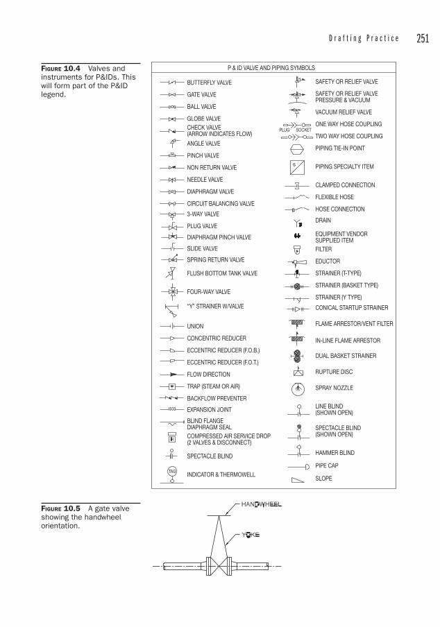
D r a f t i n g P r a c t i c e 251
P & ID VALVE AND PIPING SYMBOLS
PLUG SOCKET
BUTTERFLY VALVE
GATE VALVE
BALL VALVE
GLOBE VALVECHECK VALVE(ARROW INDICATES FLOW)
ANGLE VALVE
PINCH VALVE
NON RETURN VALVE
NEEDLE VALVE
DIAPHRAGM VALVE
CIRCUIT BALANCING VALVE
3-WAY VALVE
PLUG VALVE
DIAPHRAGM PINCH VALVE
SLIDE VALVE
SPRING RETURN VALVE
FLUSH BOTTOM TANK VALVE
FOUR-WAY VALVE
“Y” STRAINER W/VALVE
UNION
CONCENTRIC REDUCER
ECCENTRIC REDUCER (F.O.B.)
ECCENTRIC REDUCER (F.O.T.)
FLOW DIRECTION
TRAP (STEAM OR AIR)
BACKFLOW PREVENTER
EXPANSION JOINT
BLIND FLANGEDIAPHRAGM SEALCOMPRESSED AIR SERVICE DROP(2 VALVES & DISCONNECT)
SPECTACLE BLIND
INDICATOR & THERMOWELL
SAFETY OR RELIEF VALVE
SAFETY OR RELIEF VALVEPRESSURE & VACUUM
VACUUM RELIEF VALVE
ONE WAY HOSE COUPLING
TWO WAY HOSE COUPLING
PIPING TIE-IN POINT
PIPING SPECIALTY ITEM
CLAMPED CONNECTION
FLEXIBLE HOSE
HOSE CONNECTION
DRAIN
EQUIPMENT VENDORSUPPLIED ITEMFILTER
EDUCTOR
STRAINER (T-TYPE)
STRAINER (BASKET TYPE)
STRAINER (Y TYPE)
CONICAL STARTUP STRAINER
FLAME ARRESTOR/VENT FILTER
IN-LINE FLAME ARRESTOR
DUAL BASKET STRAINER
RUPTURE DISC
SPRAY NOZZLE
LINE BLIND(SHOWN OPEN)
SPECTACLE BLIND(SHOWN OPEN)
HAMMER BLIND
PIPE CAP
SLOPETAG
FIGURE 10.4 Valves and instruments for P&IDs. This will form part of the P&ID legend.
FIGURE 10.5 A gate valve showing the handwheel orientation.
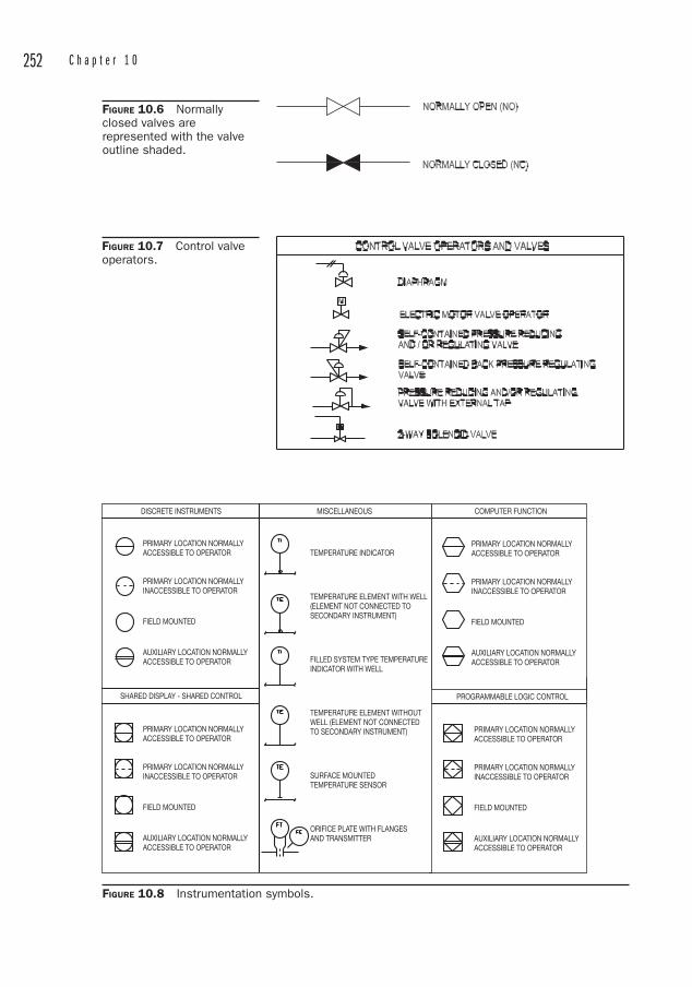
252 C h a p t e r 1 0
PRIMARY LOCATION NORMALLYACCESSIBLE TO OPERATOR
PRIMARY LOCATION NORMALLYINACCESSIBLE TO OPERATOR
FIELD MOUNTED
AUXILIARY LOCATION NORMALLYACCESSIBLE TO OPERATOR
COMPUTER FUNCTION
PROGRAMMABLE LOGIC CONTROL
PRIMARY LOCATION NORMALLYACCESSIBLE TO OPERATOR
PRIMARY LOCATION NORMALLYINACCESSIBLE TO OPERATOR
FIELD MOUNTED
AUXILIARY LOCATION NORMALLYACCESSIBLE TO OPERATOR
FIGURE 10.6 Normally closed valves are represented with the valve outline shaded.
FIGURE 10.7 Control valve operators.
DISCRETE INSTRUMENTS MISCELLANEOUS
PRIMARY LOCATION NORMALLYACCESSIBLE TO OPERATOR
PRIMARY LOCATION NORMALLYINACCESSIBLE TO OPERATOR
FIELD MOUNTED
AUXILIARY LOCATION NORMALLYACCESSIBLE TO OPERATOR
TEMPERATURE INDICATOR
TEMPERATURE ELEMENT WITH WELL(ELEMENT NOT CONNECTED TOSECONDARY INSTRUMENT)
FILLED SYSTEM TYPE TEMPERATUREINDICATOR WITH WELL
TEMPERATURE ELEMENT WITHOUT WELL (ELEMENT NOT CONNECTED TO SECONDARY INSTRUMENT)
SURFACE MOUNTED TEMPERATURE SENSOR
ORIFICE PLATE WITH FLANGESAND TRANSMITTER
SHARED DISPLAY - SHARED CONTROL
PRIMARY LOCATION NORMALLYACCESSIBLE TO OPERATOR
PRIMARY LOCATION NORMALLYINACCESSIBLE TO OPERATOR
FIELD MOUNTED
AUXILIARY LOCATION NORMALLYACCESSIBLE TO OPERATOR
FIGURE 10.8 Instrumentation symbols.
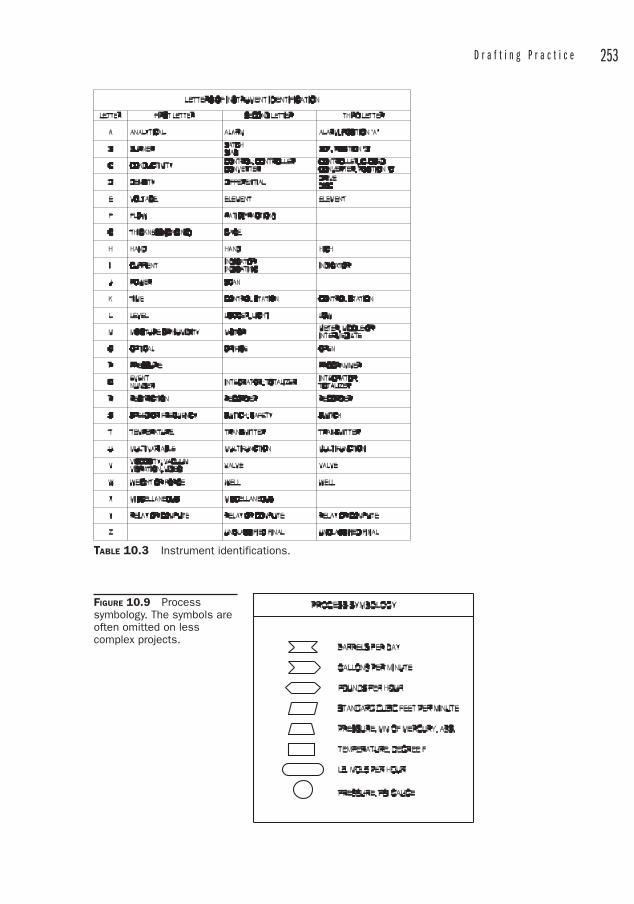
D r a f t i n g P r a c t i c e 253
TABLE 10.3 Instrument identifications.
FIGURE 10.9 Processsymbology. The symbols are often omitted on less complex projects.
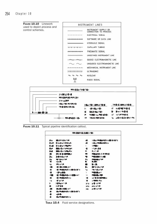
254 C h a p t e r 1 0
FIGURE 10.10 Linework used to depict process and control schemes.
FIGURE 10.11 Typical pipeline identifi cation callout.
TABLE 10.4 Fluid service designations.

D r a f t i n g P r a c t i c e 255
FIGURE 10.12 Generalsymbols.
Welding Symbols Welding has evolved into a highly technical science, and information is conveyed to the welder via the standard symbols shown in Figures 10.13 and 10.14. Note that the reference line and the arrow are the only required elements of the symbol. The arrow may be placed on the left or right hand side of the reference line, but the other elements, when used, must be placed in the locations specified.
The welding symbols are intended as a convenient “short-hand” method of conveying a lot of information in a little space. Welding information can also be indicated via notes, details, specifications, and so on.
Drafting Practices for PipingPiping Plans and ElevationsThe most common piping drawing is the plan view, which shows an overhead layout of the piping and its relationship to the surrounding structure and equipment. A good scale for piping plans is 1/4” � 1’-0”, but other scales are useful. For projects other than cross-country piping, scales smaller than 1/8” � 1’-0” are to be avoided. Too much detail is lost at these small scales and elevations and details must be relied on to fill in the missing information.
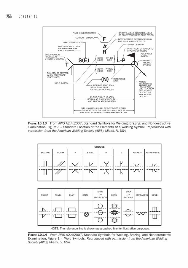
256 C h a p t e r 1 0
FIGURE 10.13 From AWS A2.4:2007, Standard Symbols for Welding, Brazing, and Nondestructive Examination, Figure 3 – Standard Location of the Elements of a Welding Symbol. Reproduced with permission from the American Welding Society (AWS), Miami, FL USA.
NOTE: The reference line is shown as a dashed line for illustrative purposes.
FIGURE 10.14 From AWS A2.4:2007, Standard Symbols for Welding, Brazing, and Nondestructive Examination, Figure 1 – Weld Symbols. Reproduced with permission from the American Welding Society (AWS), Miami, FL USA.
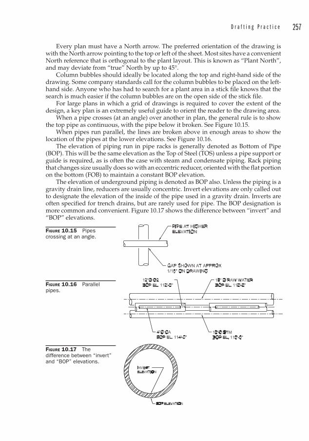
D r a f t i n g P r a c t i c e 257
Every plan must have a North arrow . The preferred orientation of the drawing is with the North arrow pointing to the top or left of the sheet. Most sites have a convenient North reference that is orthogonal to the plant layout. This is known as “Plant North”, and may deviate from “true” North by up to 45°.
Column bubbles should ideally be located along the top and right-hand side of the drawing. Some company standards call for the column bubbles to be placed on the left-hand side. Anyone who has had to search for a plant area in a stick file knows that the search is much easier if the column bubbles are on the open side of the stick file.
For large plans in which a grid of drawings is required to cover the extent of the design, a key plan is an extremely useful guide to orient the reader to the drawing area.
When a pipe crosses (at an angle) over another in plan, the general rule is to show the top pipe as continuous, with the pipe below it broken. See Figure 10.15.
When pipes run parallel, the lines are broken above in enough areas to show the location of the pipes at the lower elevations. See Figure 10.16.
The elevation of piping run in pipe racks is generally denoted as Bottom of Pipe (BOP ). This will be the same elevation as the Top of Steel (TOS) unless a pipe support or guide is required, as is often the case with steam and condensate piping. Rack piping that changes size usually does so with an eccentric reducer, oriented with the flat portion on the bottom (FOB) to maintain a constant BOP elevation.
The elevation of underground piping is denoted as BOP also. Unless the piping is a gravity drain line, reducers are usually concentric. Invert elevations are only called out to designate the elevation of the inside of the pipe used in a gravity drain. Inverts are often specified for trench drains, but are rarely used for pipe. The BOP designation is more common and convenient. Figure 10.17 shows the difference between “invert” and “BOP” elevations.
FIGURE 10.15 Pipescrossing at an angle.
FIGURE 10.16 Parallel pipes.
FIGURE 10.17 Thedifference between “invert” and “BOP” elevations.
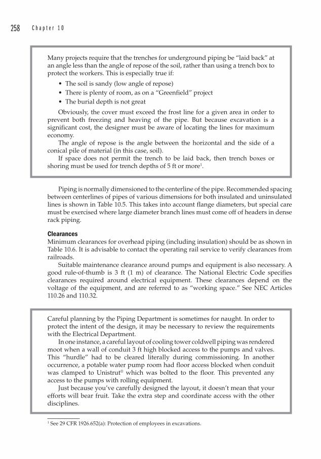
258 C h a p t e r 1 0
Many projects require that the trenches for underground piping be “laid back” at an angle less than the angle of repose of the soil, rather than using a trench box to protect the workers. This is especially true if:
• The soil is sandy (low angle of repose )• There is plenty of room, as on a “Greenfield” project• The burial depth is not great
Obviously, the cover must exceed the frost line for a given area in order to prevent both freezing and heaving of the pipe. But because excavation is a significant cost, the designer must be aware of locating the lines for maximum economy.
The angle of repose is the angle between the horizontal and the side of a conical pile of material (in this case, soil).
If space does not permit the trench to be laid back, then trench boxes or shoring must be used for trench depths of 5 ft or more1.
Piping is normally dimensioned to the centerline of the pipe. Recommended spacing between centerlines of pipes of various dimensions for both insulated and uninsulated lines is shown in Table 10.5. This takes into account flange diameters, but special care must be exercised where large diameter branch lines must come off of headers in dense rack piping .
Clearances Minimum clearances for overhead piping (including insulation) should be as shown in Table 10.6. It is advisable to contact the operating rail service to verify clearances from railroads.
Suitable maintenance clearance around pumps and equipment is also necessary. A good rule-of-thumb is 3 ft (1 m) of clearance. The National Electric Code specifies clearances required around electrical equipment. These clearances depend on the voltage of the equipment, and are referred to as “working space .” See NEC Articles 110.26 and 110.32.
Careful planning by the Piping Department is sometimes for naught. In order to protect the intent of the design, it may be necessary to review the requirements with the Electrical Department.
In one instance, a careful layout of cooling tower coldwell piping was rendered moot when a wall of conduit 3 ft high blocked access to the pumps and valves. This “hurdle” had to be cleared literally during commissioning. In another occurrence, a potable water pump room had floor access blocked when conduit was clamped to Unistrut® which was bolted to the floor. This prevented any access to the pumps with rolling equipment.
Just because you’ve carefully designed the layout, it doesn’t mean that your efforts will bear fruit. Take the extra step and coordinate access with the other disciplines.
1 See 29 CFR 1926.652(a): Protection of employees in excavations.
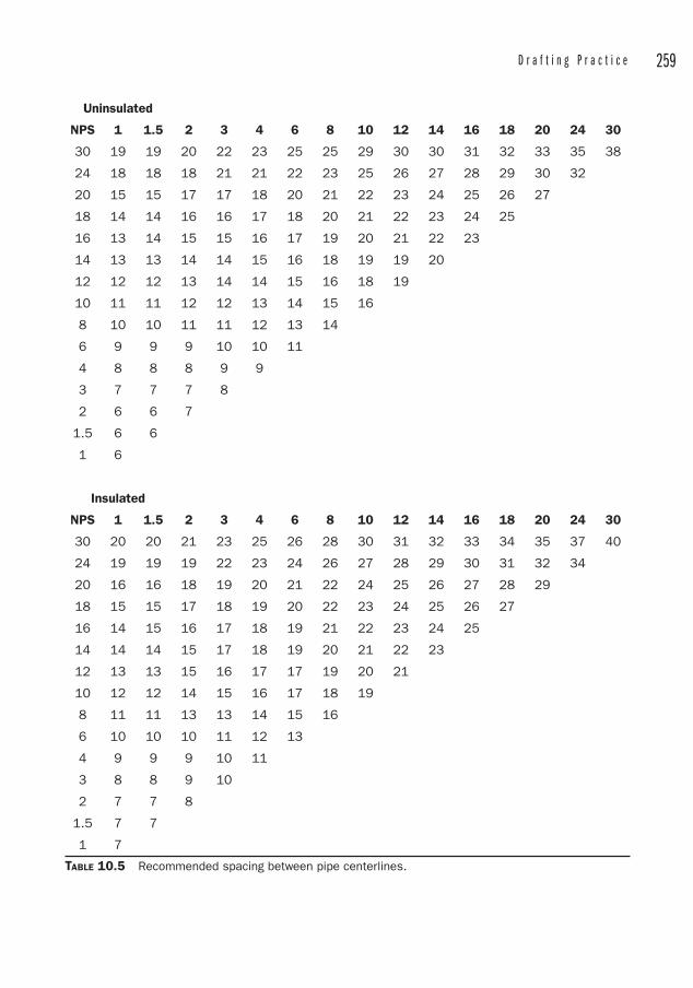
D r a f t i n g P r a c t i c e 259
Uninsulated
NPS 1 1.5 2 3 4 6 8 10 12 14 16 18 20 24 30
30 19 19 20 22 23 25 25 29 30 30 31 32 33 35 38
24 18 18 18 21 21 22 23 25 26 27 28 29 30 32
20 15 15 17 17 18 20 21 22 23 24 25 26 27
18 14 14 16 16 17 18 20 21 22 23 24 25
16 13 14 15 15 16 17 19 20 21 22 23
14 13 13 14 14 15 16 18 19 19 20
12 12 12 13 14 14 15 16 18 19
10 11 11 12 12 13 14 15 16
8 10 10 11 11 12 13 14
6 9 9 9 10 10 11
4 8 8 8 9 9
3 7 7 7 8
2 6 6 7
1.5 6 6
1 6
Insulated
NPS 1 1.5 2 3 4 6 8 10 12 14 16 18 20 24 30
30 20 20 21 23 25 26 28 30 31 32 33 34 35 37 40
24 19 19 19 22 23 24 26 27 28 29 30 31 32 34
20 16 16 18 19 20 21 22 24 25 26 27 28 29
18 15 15 17 18 19 20 22 23 24 25 26 27
16 14 15 16 17 18 19 21 22 23 24 25
14 14 14 15 17 18 19 20 21 22 23
12 13 13 15 16 17 17 19 20 21
10 12 12 14 15 16 17 18 19
8 11 11 13 13 14 15 16
6 10 10 10 11 12 13
4 9 9 9 10 11
3 8 8 9 10
2 7 7 8
1.5 7 7
1 7
TABLE 10.5 Recommended spacing between pipe centerlines.
260 C h a p t e r 1 0
Field Routed Piping and Single-Line versus Double-Line Piping Usually 2 in diameter and smaller piping is represented on drawings as a single line and 2 1/2 in and larger is shown as double-line. That is, the OD of the pipe is represented at full size.
The exact split between single-line and double-line representations may vary somewhat, depending on the scale of the project or the standards prepared by the Chief Engineer.
The split at 2 in is a good rule-of-thumb however, and it also designates a good split between field-routed piping and dimensioned piping. This is a convenient coincidence, because it quickly shows what may be field-routed.
Field-routed piping is a concept that saves design time. The idea is that small-bore piping is easy enough to route from Point A to Point B (the “Tie Points ”) around the obstacles in between that an inordinate amount of time would be spent in designing and dimensioning the routing. Piping of such small sizes is very flexible and so pipe stresses would rarely need to be considered. It is more economical to allow the fitters to establish the route. Sometimes a list is simply provided with the tie points and the entire route is left to the contractor . Sometimes, however, it may be advantageous to show the anticipated routing, and then this is represented with the single line piping, which may also be required to show valve, equipment, or instrumentation locations.
Several years ago, a consulting firm developed a concept for quickly designing steel mills that relied on the contractors to route the piping and electrical lines. They marketed it as a cost savings for the Owner, as well as a means to compress the schedule.
While this approach may have some merit on the surface, most engineers would object to the shift of responsibility to the contractor . The contractor would have to have somebody perform material take-offs and plan the routing anyway. Many companies would prefer to have that work performed by qualified personnel, whether they work for the engineer or the contractor.
From a technical, operational, and maintenance standpoint, it is better to have the layout performed by engineers and designers. The “minimal design” practice has not been popular in the U.S. recently, and has given way to the more traditional and proven design practices.
Piping DetailsDetail drawings are often prepared at 3/8” � 1’-0” since this scale offers room to provide lots of information on the drawing sheet. Engineering companies take advantage of re-usable standard details for common equipment connections, steam trap installations, pipe supports, and the like. Many of these are available as pre-drawn CAD details through third party suppliers, and these save considerable time and effort.
Description Feet-Inches mmOver Roadways 17�-0� 5200Over Walkways 6�-8� 2035In Confined Spaces 6�-8� 2035Yard Piping 17�-0� 5200Over Railroads (Top of Rail) 23�-0� 7010Adjacent to Railroads (From Centerline) 12�-0� 3660
TABLE 10.6 Minimum pipeline clearances.
261
CHAPTER 11Pressure Drop Calculations
The term “fast track ” as it is applied to engineering projects is defined as a project in which design is taking place before all of the information is available. In fact, portions of the project may be under construction while other portions are still in design. One of the first efforts in a piping project is to calculate pressure drops. This exercise is often required even before adequate information is available. Welcome to fast track design.
The reason that the pressure drop calculations are so important at this stage is because long-lead items such as pumps, motor starters, and switchgear must be specified, bid, and purchased. The fact that this must all occur while the vendor is fine-tuning energy balances (and hence flow rates) only adds to the stress under which the engineer must operate. Fortunately, there are some good guesses that we can make to assure that the final result satisfies the requirements of the equipment, the plant, the project schedule, and the budget.
These guesses may relate to anticipated life of the equipment (as in the degree to which internal surfaces may become rougher as they corrode), acceptable loss coefficients through valves or fittings (since there is some variation in the published data), and of course, the intelligent selection of a contingency factor, or “factor of safety,” to account for variations in the unknowns and to provide a margin of error.
A careful accounting of the lengths and fittings is achievable by applying a methodical approach to the problem. In spite of all our care, a reasonable factor of safety of 15 percent is often applied to the end result since the last thing anyone on a piping project wants is to start a pump and have it “churn” the fluid without delivering the proper capacity at the proper pressure. For those who are worried about the inherent waste of energy that may result in a slightly oversized pump, there are always variable speed drive technologies that may be applied to the pump in order to take advantage of the affinity laws. A small reduction in pump speed can lead to significant energy savings.
Certainly a huge part of engineering is the economical application of resources to a problem, and so it is unacceptable to grossly oversize a piece of equipment due to the large capital cost as well as the domino effect of installation costs, taxes, and the cost of the necessarily larger electrical gear that would be required to keep a larger-than-necessary pump operating. Hence it is necessary to determine as closely as possible the requirements of the pump. But in no case may the pump or driver be undersized.
There are software programs available that model the piping system and flows and produce the required pump performance characteristics. These are certainly of value, but especially for simple single-line flow, hand calculations are easy and may be performed quickly without the expense of software or the all-too-frequent foibles with computers1.1 Even though they have become an inextricable part of the engineer’s life.
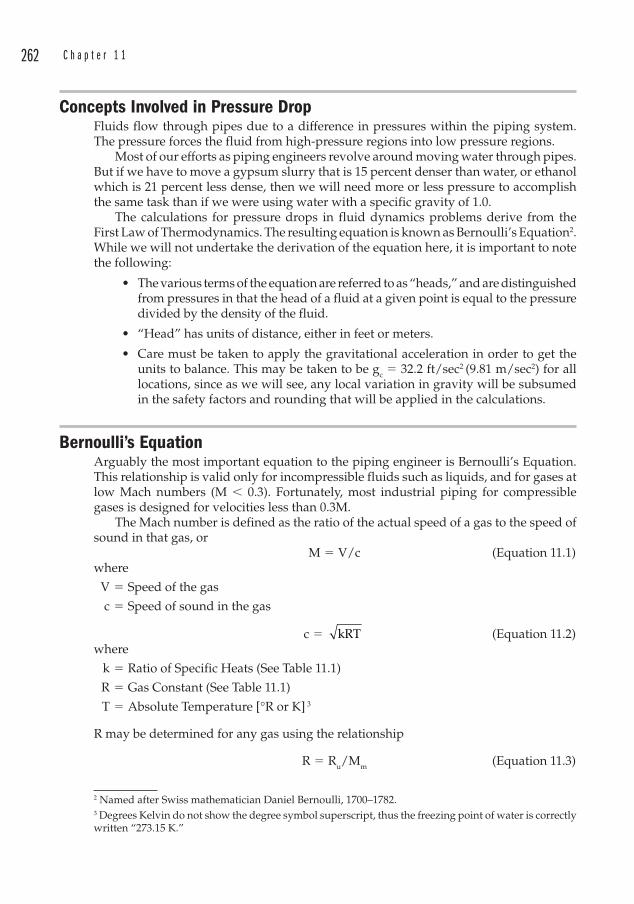
262 C h a p t e r 1 1
Concepts Involved in Pressure DropFluids flow through pipes due to a difference in pressures within the piping system. The pressure forces the fluid from high-pressure regions into low pressure regions.
Most of our efforts as piping engineers revolve around moving water through pipes. But if we have to move a gypsum slurry that is 15 percent denser than water, or ethanol which is 21 percent less dense, then we will need more or less pressure to accomplish the same task than if we were using water with a specific gravity of 1.0.
The calculations for pressure drops in fluid dynamics problems derive from the First Law of Thermodynamics. The resulting equation is known as Bernoulli’s Equation 2. While we will not undertake the derivation of the equation here, it is important to note the following:
• The various terms of the equation are referred to as “heads,” and are distinguished from pressures in that the head of a fluid at a given point is equal to the pressure divided by the density of the fluid.
• “Head” has units of distance, either in feet or meters.
• Care must be taken to apply the gravitational acceleration in order to get the units to balance. This may be taken to be gc � 32.2 ft/sec2 (9.81 m/sec2) for all locations, since as we will see, any local variation in gravity will be subsumed in the safety factors and rounding that will be applied in the calculations.
Bernoulli’s Equation Arguably the most important equation to the piping engineer is Bernoulli’s Equation. This relationship is valid only for incompressible fluids such as liquids, and for gases at low Mach numbers (M � 0.3). Fortunately, most industrial piping for compressible gases is designed for velocities less than 0.3M.
The Mach number is defined as the ratio of the actual speed of a gas to the speed of sound in that gas, or M � V/c (Equation 11.1)where
V � Speed of the gas
c � Speed of sound in the gas
c � kRT (Equation 11.2)where
k � Ratio of Specific Heats ( See Table 11.1)
R � Gas Constant (See Table 11.1)
T � Absolute Temperature [ °R or K] 3
R may be determined for any gas using the relationship
R � Ru/Mm (Equation 11.3)
2 Named after Swiss mathematician Daniel Bernoulli, 1700–1782. 3 Degrees Kelvin do not show the degree symbol superscript, thus the freezing point of water is correctly written “273.15 K. ”

P r e s s u r e D r o p C a l c u l a t i o n s 263
where
Ru � Universal Gas Constant � 1544 ft lbf / lbmole °R (8314 N m / kgmole K)
Mm � Molecular Mass of the gas
We note that the speed of sound is a function of temperature only for an ideal gas.
Example 11.1Given: Air at 100 psig flowing through a 4 in Sch 40 steel pipe at 100 ft/secFind: Is Bernoulli’s Equation valid for this flow condition?
First we find the velocity of sound in the air. We will assume that the air flowing through the pipe is 85°F. Compressed air is generally cooled after compression to drop out excessive moisture.
Applying Equation 11.2 yields
c � kRT
� �(1.40) (1717 ft °R) (85°F 460°R)2 / sec2
� 1145 ft/sec
M100
ftsec
1145ft
sec
0.09� �
Therefore, Bernoulli’s Equation is applicable to this flow condition.To further our discussion of Bernoulli’s Equation we define the two points in a
piping system in which we are interested. We identify the first point with the logical subscript 1 and the second point with the subscript 2. We further stipulate that we will apply the equation in English units.
Bernoulli’s equation is given by
p v2g
z hp v
21
1
12
c1 A
2
2
22
� � � � �
� �
ggz h h
c2 E f � � � (Equation 11.4)
GasChemicalSymbol
MolecularMass, Mm
R cp cv k
J/kg Kft lbf/lbm °R
ft2/sec2
°R J/kg KBTU/lbm
°R J/kg KBTU/lbm
°R
Air 28.98 286.9 53.33 1717 1.004 0.2399 717.4 0.1713 1.40CarbonDioxide
CO2 44.01 188.9 35.11 1130 840.4 0.2007 651.4 0.1556 1.29
CarbonMonoxide
CO 28.01 296.8 55.17 1776 1039 0.2481 742.1 0.1772 1.40
Helium He 4.003 2077 386.1 12,432 5225 1.248 3147 0.7517 1.66Hydrogen H2 2.016 4124 766.5 24,681 14,180 3.388 10,060 2.402 1.41Methane CH4 16.04 518.3 96.32 3102 2190 0.5231 1672 0.3993 1.31Nitrogen N2 28.01 296.8 55.16 1776 1039 0.2481 742.0 0.1772 1.40Oxygen O2 32.00 259.8 48.29 1555 909.4 0.2172 649.6 0.1551 1.40Steam H2O 18.02 461.4 85.78 2762 2000 0.478 1540 0.368 1.30
TABLE 11.1 Properties of some common gases.
264 C h a p t e r 1 1
where
p � pressure [lb/ft2]
� � density [lb/ft3]
v � velocity [ft/sec]
gc � the gravitational constant � 32.2 ft/sec2 (9.81 m/sec2)
z � elevation [ft]
hA � Head added to the process, as by a pump [ft]
hE � Head extracted from the process, as from a turbine [ft]
hf � Head loss due to friction [ft]
In trying to properly size a pump, the bulk of the effort lies in the last term, determining the head loss due to friction.
The equation is usually rewritten so that similar terms can be subtracted from one another.
h
p p v2g
v2gA
2
2
1
1
22
c
12
� �
� �
� � ⎛
⎝⎜⎞
⎠⎟ cc2 1 E f(z z ) h h
⎛
⎝⎜
⎞
⎠⎟ � � � �
(Equation 11.5)
Because the density is constant for an incompressible fluid, this may be written as
h
p p v v2gA
2 1 22
12
c
� �
� �
�
⎛⎝⎜
⎞⎠⎟
⎛
⎝⎜
⎞
⎠⎟ �� � � � (z z ) h h2 1 E f
(Equation 11.6)
Pressure HeadThe term p/� is referred to as the “pressure head”. This has the dimensions of length and is calculated in units of feet or meters. Note that a conversion factor must be applied if the pressure is given in psi and the density is in lb/ft3. For example, water at 65 psi and a density of 62.4 lb/ft3 has a pressure head of
p/� � (65 lb/in2) (12 in /ft)2 / (62.4 lb/ft3) � 150 ft
In reality, the pressures are subtracted prior to performing the conversion from psi into PSF.
Velocity HeadThe term v/2g c is referred to as the “velocity head.” This is the head due to kinetic energy. This term is usually very small, and while it would be technically incorrect to disregard it, for practical piping problems its contribution is often negligible. Because the first point of the system often refers to a lake, tank, or similar large container, the v1 term can be taken to be zero in such cases, since the velocity of the surface of a lake or tank does not appreciably change due to pumping out of it. The same may be true of the discharge point 2.
The velocity head plays a role in calculating friction head losses through fittings.
Elevation HeadThe z term is the “elevation head.” This is the head due to potential energy, and accounts for that portion of the head required to move the fluid from one elevation to another.
P r e s s u r e D r o p C a l c u l a t i o n s 265
Friction LossesWhile there a re several software products available to aid in computing friction losses, the ability to perform hand calculations should not be underestimated. To begin with, most of the effort centers around obtaining a fair count of the lengths of pipe and the number of fittings. Once that is accomplished, the rest is accounting, and a manual calculation system is usually no more difficult than modeling the pipe system in a format that can be understood by the piping software.
Friction losses depend on several variables:
• Flow rate• Diameter• Type of pipe (Roughness)• Length of pipe (Major Losses)• Number and sizes of fittings and valves (Minor Losses)• Entrance a nd Exit Losses (Minor Losses)
The diameter of the pipe is determined based on velocity. The velocity is usually based on recommended rules-of-thumb that have been used with success over the years. Some of these recommended velocities appear in Table 11.2. These recommended velocities represent a compromise between what is thought to be a reasonable energy cost in overcoming the friction balanced against the first cost of the installed pipe. When sizing pipe it is useful to consider that the incremental cost of increasing the pipe by one size is usually minimal, and the increase in cost may often be justified by the reduced energy costs in pumping the fluid, or the ability to increase capacity at some future time without having to add another separate pipe. If, however, the application involves solids in suspension, then all bets are off: minimum velocities will be required in order to keep the solids from dropping out of the flow stream.
Flow rates in GPM for common pipe sizes and practical velocities are given for various pipe schedules in Tables 11.3 through 11.7. These tables can be used to quickly find the diameter of pipe if the desired flow in GPM is known.
WaterDepending on the particular application, water velocities should be between 3 and 10 fps (1 to 3 m/sec). The danger of creating water hammer increases abo ve 10 fps.
Pump suctions operate in a region of low pressure, and high velocities can cause a reduction in the vapor pressure, creating local vaporization of the water. This leads to small vapor bubbles which then collapse inside the pump, and the result is an erosive condition that can lead to early pump failure. This phenomenon may occur with any liquid and is known as “cavitation.” Pump suction lines should always be sized for low velocities between 2 and 5 fps (0.6 to 1.5 m/sec) to reduce the chance of creating cavitation in the pump.
Hydronic piping should be sized for a maximum pressure loss of 4 ft of head per 100 ft of pipe. This is a requirement of ASHRAE 90.1 Energy Standa rd for Buildings Except Low-Rise Residential Buildings. The intent is to limit the friction loss, and hence, the energy consumption required to pump water through a building. Because hydronic piping is usually closed-loop, most of the energy consumption derives from friction losses as opposed to moving the fluid to a higher elevation.
(text continues on page 270)
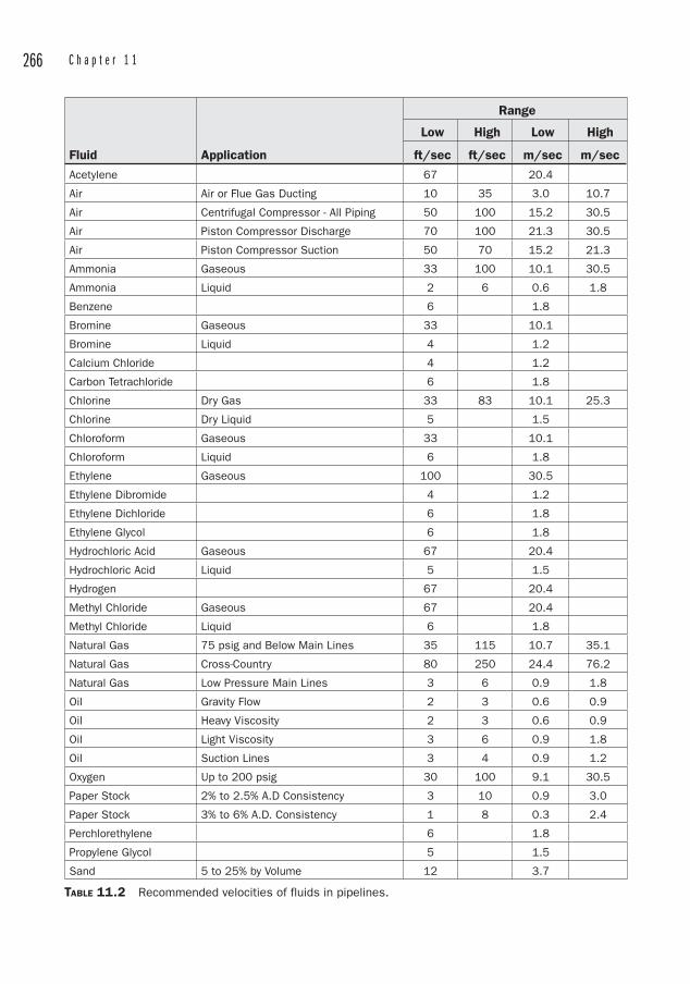
266 C h a p t e r 1 1
Fluid Application
Range
Low High Low High
ft/sec ft/sec m/sec m/sec
Acetylene 67 20.4
Air Air or Flue Gas Ducting 10 35 3.0 10.7
Air Centrifugal Compressor - All Piping 50 100 15.2 30.5
Air Piston Compressor Discharge 70 100 21.3 30.5
Air Piston Compressor Suction 50 70 15.2 21.3
Ammonia Gaseous 33 100 10.1 30.5
Ammonia Liquid 2 6 0.6 1.8
Benzene 6 1.8
Bromine Gaseous 33 10.1
Bromine Liquid 4 1.2
Calcium Chloride 4 1.2
Carbon Tetrachloride 6 1.8
Chlorine Dry Gas 33 83 10.1 25.3
Chlorine Dry Liquid 5 1.5
Chloroform Gaseous 33 10.1
Chloroform Liquid 6 1.8
Ethylene Gaseous 100 30.5
Ethylene Dibromide 4 1.2
Ethylene Dichloride 6 1.8
Ethylene Glycol 6 1.8
Hydrochloric Acid Gaseous 67 20.4
Hydrochloric Acid Liquid 5 1.5
Hydrogen 67 20.4
Methyl Chloride Gaseous 67 20.4
Methyl Chloride Liquid 6 1.8
Natural Gas 75 psig and Below Main Lines 35 115 10.7 35.1
Natural Gas Cross-Country 80 250 24.4 76.2
Natural Gas Low Pressure Main Lines 3 6 0.9 1.8
Oil Gravity Flow 2 3 0.6 0.9
Oil Heavy Viscosity 2 3 0.6 0.9
Oil Light Viscosity 3 6 0.9 1.8
Oil Suction Lines 3 4 0.9 1.2
Oxygen Up to 200 psig 30 100 9.1 30.5
Paper Stock 2% to 2.5% A.D Consistency 3 10 0.9 3.0
Paper Stock 3% to 6% A.D. Consistency 1 8 0.3 2.4
Perchlorethylene 6 1.8
Propylene Glycol 5 1.5
Sand 5 to 25% by Volume 12 3.7
TABLE 11.2 Recommended velocities of fluids in pipelines.
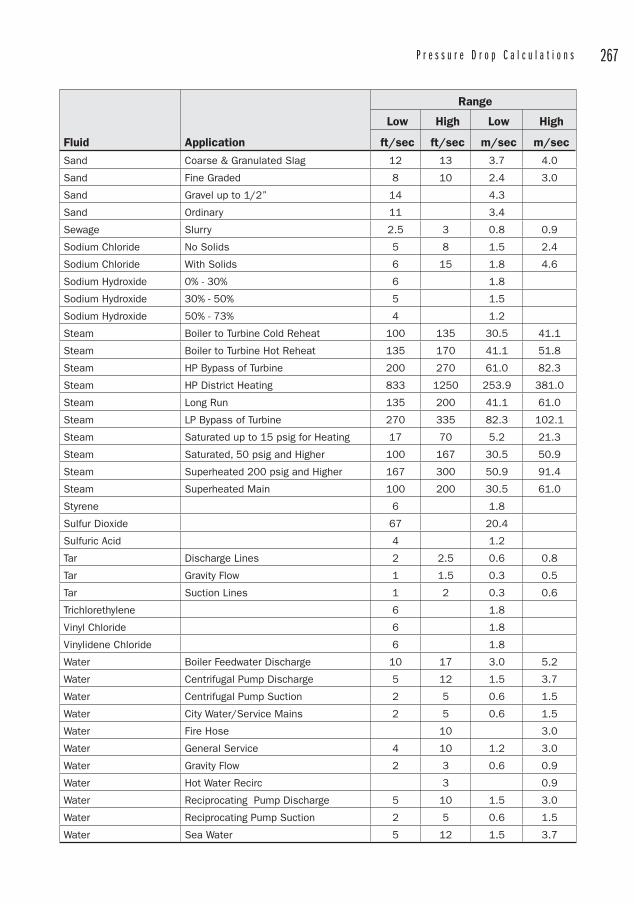
P r e s s u r e D r o p C a l c u l a t i o n s 267
Fluid Application
Range
Low High Low High
ft/sec ft/sec m/sec m/sec
Sand Coarse & Granulated Slag 12 13 3.7 4.0
Sand Fine Graded 8 10 2.4 3.0
Sand Gravel up to 1/2” 14 4.3
Sand Ordinary 11 3.4
Sewage Slurry 2.5 3 0.8 0.9
Sodium Chloride No Solids 5 8 1.5 2.4
Sodium Chloride With Solids 6 15 1.8 4.6
Sodium Hydroxide 0% - 30% 6 1.8
Sodium Hydroxide 30% - 50% 5 1.5
Sodium Hydroxide 50% - 73% 4 1.2
Steam Boiler to Turbine Cold Reheat 100 135 30.5 41.1
Steam Boiler to Turbine Hot Reheat 135 170 41.1 51.8
Steam HP Bypass of Turbine 200 270 61.0 82.3
Steam HP District Heating 833 1250 253.9 381.0
Steam Long Run 135 200 41.1 61.0
Steam LP Bypass of Turbine 270 335 82.3 102.1
Steam Saturated up to 15 psig for Heating 17 70 5.2 21.3
Steam Saturated, 50 psig and Higher 100 167 30.5 50.9
Steam Superheated 200 psig and Higher 167 300 50.9 91.4
Steam Superheated Main 100 200 30.5 61.0
Styrene 6 1.8
Sulfur Dioxide 67 20.4
Sulfuric Acid 4 1.2
Tar Discharge Lines 2 2.5 0.6 0.8
Tar Gravity Flow 1 1.5 0.3 0.5
Tar Suction Lines 1 2 0.3 0.6
Trichlorethylene 6 1.8
Vinyl Chloride 6 1.8
Vinylidene Chloride 6 1.8
Water Boiler Feedwater Discharge 10 17 3.0 5.2
Water Centrifugal Pump Discharge 5 12 1.5 3.7
Water Centrifugal Pump Suction 2 5 0.6 1.5
Water City Water/Service Mains 2 5 0.6 1.5
Water Fire Hose 10 3.0
Water General Service 4 10 1.2 3.0
Water Gravity Flow 2 3 0.6 0.9
Water Hot Water Recirc 3 0.9
Water Reciprocating Pump Discharge 5 10 1.5 3.0
Water Reciprocating Pump Suction 2 5 0.6 1.5
Water Sea Water 5 12 1.5 3.7
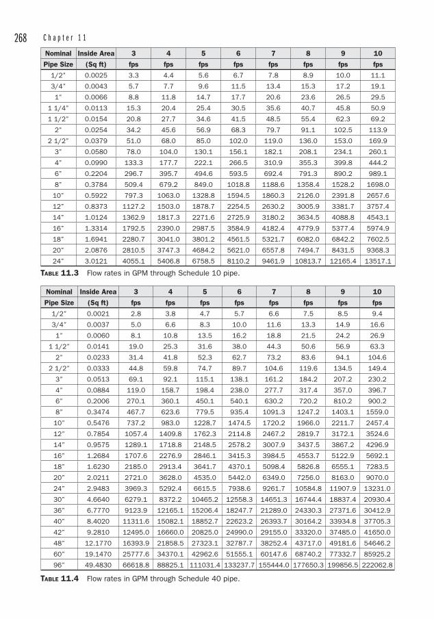
268 C h a p t e r 1 1
Nominal Inside Area 3 4 5 6 7 8 9 10
Pipe Size (Sq ft) fps fps fps fps fps fps fps fps
1/2” 0.0025 3.3 4.4 5.6 6.7 7.8 8.9 10.0 11.1
3/4” 0.0043 5.7 7.7 9.6 11.5 13.4 15.3 17.2 19.1
1” 0.0066 8.8 11.8 14.7 17.7 20.6 23.6 26.5 29.5
1 1/4” 0.0113 15.3 20.4 25.4 30.5 35.6 40.7 45.8 50.9
1 1/2” 0.0154 20.8 27.7 34.6 41.5 48.5 55.4 62.3 69.2
2” 0.0254 34.2 45.6 56.9 68.3 79.7 91.1 102.5 113.9
2 1/2” 0.0379 51.0 68.0 85.0 102.0 119.0 136.0 153.0 169.9
3” 0.0580 78.0 104.0 130.1 156.1 182.1 208.1 234.1 260.1
4” 0.0990 133.3 177.7 222.1 266.5 310.9 355.3 399.8 444.2
6” 0.2204 296.7 395.7 494.6 593.5 692.4 791.3 890.2 989.1
8” 0.3784 509.4 679.2 849.0 1018.8 1188.6 1358.4 1528.2 1698.0
10” 0.5922 797.3 1063.0 1328.8 1594.5 1860.3 2126.0 2391.8 2657.6
12” 0.8373 1127.2 1503.0 1878.7 2254.5 2630.2 3005.9 3381.7 3757.4
14” 1.0124 1362.9 1817.3 2271.6 2725.9 3180.2 3634.5 4088.8 4543.1
16” 1.3314 1792.5 2390.0 2987.5 3584.9 4182.4 4779.9 5377.4 5974.9
18” 1.6941 2280.7 3041.0 3801.2 4561.5 5321.7 6082.0 6842.2 7602.5
20” 2.0876 2810.5 3747.3 4684.2 5621.0 6557.8 7494.7 8431.5 9368.3
24” 3.0121 4055.1 5406.8 6758.5 8110.2 9461.9 10813.7 12165.4 13517.1
TABLE 11.3 Flow rates in GPM through Schedule 10 pipe.
Nominal Inside Area 3 4 5 6 7 8 9 10
Pipe Size (Sq ft) fps fps fps fps fps fps fps fps
1/2” 0.0021 2.8 3.8 4.7 5.7 6.6 7.5 8.5 9.4
3/4” 0.0037 5.0 6.6 8.3 10.0 11.6 13.3 14.9 16.6
1” 0.0060 8.1 10.8 13.5 16.2 18.8 21.5 24.2 26.9
1 1/2” 0.0141 19.0 25.3 31.6 38.0 44.3 50.6 56.9 63.3
2” 0.0233 31.4 41.8 52.3 62.7 73.2 83.6 94.1 104.6
2 1/2” 0.0333 44.8 59.8 74.7 89.7 104.6 119.6 134.5 149.4
3” 0.0513 69.1 92.1 115.1 138.1 161.2 184.2 207.2 230.2
4” 0.0884 119.0 158.7 198.4 238.0 277.7 317.4 357.0 396.7
6” 0.2006 270.1 360.1 450.1 540.1 630.2 720.2 810.2 900.2
8” 0.3474 467.7 623.6 779.5 935.4 1091.3 1247.2 1403.1 1559.0
10” 0.5476 737.2 983.0 1228.7 1474.5 1720.2 1966.0 2211.7 2457.4
12” 0.7854 1057.4 1409.8 1762.3 2114.8 2467.2 2819.7 3172.1 3524.6
14” 0.9575 1289.1 1718.8 2148.5 2578.2 3007.9 3437.5 3867.2 4296.9
16” 1.2684 1707.6 2276.9 2846.1 3415.3 3984.5 4553.7 5122.9 5692.1
18” 1.6230 2185.0 2913.4 3641.7 4370.1 5098.4 5826.8 6555.1 7283.5
20” 2.0211 2721.0 3628.0 4535.0 5442.0 6349.0 7256.0 8163.0 9070.0
24” 2.9483 3969.3 5292.4 6615.5 7938.6 9261.7 10584.8 11907.9 13231.0
30” 4.6640 6279.1 8372.2 10465.2 12558.3 14651.3 16744.4 18837.4 20930.4
36” 6.7770 9123.9 12165.1 15206.4 18247.7 21289.0 24330.3 27371.6 30412.9
40” 8.4020 11311.6 15082.1 18852.7 22623.2 26393.7 30164.2 33934.8 37705.3
42” 9.2810 12495.0 16660.0 20825.0 24990.0 29155.0 33320.0 37485.0 41650.0
48” 12.1770 16393.9 21858.5 27323.1 32787.7 38252.4 43717.0 49181.6 54646.2
60” 19.1470 25777.6 34370.1 42962.6 51555.1 60147.6 68740.2 77332.7 85925.2
96” 49.4830 66618.8 88825.1 111031.4 133237.7 155444.0 177650.3 199856.5 222062.8
TABLE 11.4 Flow rates in GPM through Schedule 40 pipe.
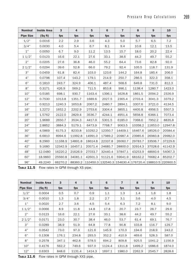
P r e s s u r e D r o p C a l c u l a t i o n s 269
Nominal Inside Area 3 4 5 6 7 8 9 10
Pipe Size (Sq ft) fps fps fps fps fps fps fps fps
1/2” 0.0016 2.2 2.9 3.6 4.3 5.0 5.7 6.5 7.2
3/4” 0.0030 4.0 5.4 6.7 8.1 9.4 10.8 12.1 13.5
1” 0.0050 6.7 9.0 11.2 13.5 15.7 18.0 20.2 22.4
1 1/2” 0.0123 16.6 22.1 27.6 33.1 38.6 44.2 49.7 55.2
2” 0.0205 27.6 36.8 46.0 55.2 64.4 73.6 82.8 92.0
2 1/2” 0.0294 39.6 52.8 66.0 79.2 92.4 105.5 118.7 131.9
3” 0.0459 61.8 82.4 103.0 123.6 144.2 164.8 185.4 206.0
4” 0.0798 107.4 143.2 179.1 214.9 250.7 286.5 322.3 358.1
6” 0.1810 243.7 324.9 406.1 487.4 568.6 649.8 731.0 812.3
8” 0.3171 426.9 569.2 711.5 853.8 996.1 1138.4 1280.7 1423.0
10” 0.5185 698.1 930.7 1163.4 1396.1 1628.8 1861.5 2094.2 2326.9
12” 0.7530 1013.8 1351.7 1689.6 2027.5 2365.4 2703.4 3041.3 3379.2
14” 0.9213 1240.3 1653.8 2067.2 2480.7 2894.1 3307.6 3721.0 4134.5
16” 1.2272 1652.2 2202.9 2753.6 3304.4 3855.1 4405.8 4956.5 5507.3
18” 1.5762 2122.0 2829.4 3536.7 4244.1 4951.4 5658.8 6366.1 7073.4
20” 1.9689 2650.7 3534.3 4417.9 5301.5 6185.0 7068.6 7952.2 8835.8
24” 2.8852 3884.3 5179.1 6473.9 7768.7 9063.5 10358.2 11653.0 12947.8
30” 4.5869 6175.3 8233.8 10292.2 12350.7 14409.1 16467.6 18526.0 20584.4
36” 6.6810 8994.6 11992.8 14991.0 17989.2 20987.4 23985.6 26983.8 29982.0
40” 8.2960 11168.9 14891.8 18614.8 22337.8 26060.7 29783.7 33506.7 37229.6
42” 9.1680 12342.9 16457.1 20571.4 24685.7 28800.0 32914.3 37028.6 41142.9
48” 12.0480 16220.2 21626.9 27033.7 32440.4 37847.1 43253.9 48660.6 54067.3
60” 18.9860 25560.8 34081.1 42601.3 51121.6 59641.9 68162.2 76682.4 85202.7
96” 49.2240 66270.2 88360.2 110450.3 132540.3 154630.4 176720.4 198810.5 220900.5
TABLE 11.5 Flow rates in GPM through XS pipe.
Nominal Inside Area 3 4 5 6 7 8 9 10
Pipe Size (Sq ft) fps fps fps fps fps fps fps fps
1/2” 0.0004 0.5 0.7 0.9 1.1 1.3 1.4 1.6 1.8
3/4” 0.0010 1.3 1.8 2.2 2.7 3.1 3.6 4.0 4.5
1” 0.0020 2.7 3.6 4.5 5.4 6.3 7.2 8.1 9.0
1 1/2” 0.0066 8.9 11.8 14.8 17.8 20.7 23.7 26.7 29.6
2” 0.0123 16.6 22.1 27.6 33.1 38.6 44.2 49.7 55.2
2 1/2” 0.0171 23.0 30.7 38.4 46.0 53.7 61.4 69.1 76.7
3” 0.0289 38.9 51.9 64.8 77.8 90.8 103.8 116.7 129.7
4” 0.0542 73.0 97.3 121.6 145.9 170.3 194.6 218.9 243.2
6” 0.1308 176.1 234.8 293.5 352.2 410.9 469.6 528.3 587.0
8” 0.2578 347.1 462.8 578.5 694.2 809.8 925.5 1041.2 1156.9
10” 0.4176 562.2 749.6 937.0 1124.4 1311.8 1499.2 1686.6 1874.0
12” 0.6303 848.6 1131.4 1414.3 1697.1 1980.0 2262.9 2545.7 2828.6
TABLE 11.6 Flow rates in GPM through XXS pipe.
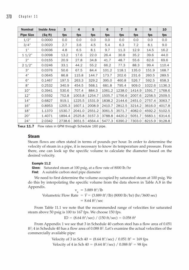
270 C h a p t e r 1 1
SteamSteam flows are often stated in terms of pounds per hour. In order to determine the velocity of steam in a pipe, it is necessary to know its temperature and pressure. From there, one can look up the specific volume to calculate the diameter based on the desired velocity.
Example 11.2Given: Saturated steam at 100 psig, at a flow rate of 8000 lb/hrFind: A suitable carbon steel pipe diameter
We need to first determine the volume occupied by saturated steam at 100 psig. We do this by interpolating the specific volume from the data shown in Table A.8 in the Appendix. vg � 3.889 ft3/lb Volumetric Flow Rate � V̇ � (3.889 ft3/lb) (8000 lb/hr) (hr/3600 sec) � 8.64 ft3/sec
From Table 11.1 we note that the recommended range of velocities for saturated steam above 50 psig is 100 to 167 fps. We choose 150 fps.
ID � (8.64 ft3/sec) / (150 ft/sec) � 0.058 ft2
From Appendix 1 we see that 3 in Schedule 40 carbon steel has a flow area of 0.051 ft2; 4 in Schedule 40 has a flow area of 0.088 ft2. Let’s examine the actual velocities of the commercially available pipe:
Velocity of 3 in Sch 40 � (8.64 ft3/sec) / 0.051 ft2 � 169 fpsVelocity of 4 in Sch 40 � (8.64 ft3/sec) / 0.088 ft2 � 98 fps
Nominal Inside Area 3 4 5 6 7 8 9 10
Pipe Size (Sq ft) fps fps fps fps fps fps fps fps
1/2” 0.0000 0.0 0.0 0.0 0.0 0.0 0.0 0.0 0.0
3/4” 0.0020 2.7 3.6 4.5 5.4 6.3 7.2 8.1 9.0
1” 0.0036 4.8 6.5 8.1 9.7 11.3 12.9 14.5 16.2
1 1/2” 0.0098 13.2 17.6 22.0 26.4 30.8 35.2 39.6 44.0
2” 0.0155 20.9 27.8 34.8 41.7 48.7 55.6 62.6 69.6
2 1/2” 0.0246 33.1 44.2 55.2 66.2 77.3 88.3 99.4 110.4
3” 0.0376 50.6 67.5 84.4 101.2 118.1 135.0 151.9 168.7
4” 0.0645 86.8 115.8 144.7 173.7 202.6 231.6 260.5 289.5
6” 0.1467 197.5 263.3 329.2 395.0 460.8 526.7 592.5 658.3
8” 0.2532 340.9 454.5 568.1 681.8 795.4 909.0 1022.6 1136.3
10” 0.3941 530.6 707.4 884.3 1061.2 1238.0 1414.9 1591.7 1768.6
12” 0.5592 752.8 1003.8 1254.7 1505.7 1756.6 2007.6 2258.5 2509.5
14” 0.6827 919.1 1225.5 1531.9 1838.2 2144.6 2451.0 2757.4 3063.7
16” 0.8953 1205.3 1607.1 2008.9 2410.7 2812.5 3214.2 3616.0 4017.8
18” 1.1370 1530.7 2041.0 2551.2 3061.5 3571.7 4082.0 4592.2 5102.5
20” 1.4071 1894.4 2525.8 3157.3 3788.8 4420.2 5051.7 5683.1 6314.6
24” 2.0342 2738.6 3651.5 4564.4 5477.3 6390.2 7303.0 8215.9 9128.8
TABLE 11.7 Flow rates in GPM through Schedule 160 pipe.
P r e s s u r e D r o p C a l c u l a t i o n s 271
The 3 in Sch 40 pipe exceeds the maximum recommended velocity, and the 4 in produces a velocity less than the low end of the recommended range. We could use 3 1/2 in diameter pipe, but that is an unusual size, so we select the 4 in diameter because it will
• Provide for possible future capacity• Decrease noise generation• Provide less friction loss
Roughness of the pipe is a function of the pipe material as well as its age. Ferrous pipes that have been in service many years may be corroded, scaled, or tubercular, and the relative roughness will have increased due to these surface irregularities. However, for low flow rates it turns out that the roughness does not matter at all. This occurs only for laminar flow, which is a special case since most industrial flow problems lie within the turbulent regime.
The number of fittings and other factors such as entrance and exit losses that contribute to the minor losses may be converted into an “Equivalent Length,” which is then added to the length of straight pipe for a total length. This exercise must be performed for each segment that has a different diameter in the system.
Much attention has been given to pressure drop calculations throughout the years, and the result is that there are several good methods to compute pressure drops. Some are certainly more convenient than others, and engineers know a good shortcut when they see one. Once again, because the majority of piping systems pertain to water, much effort has been devoted to the calculation of pressure drops through common water pipe materials.
Major LossesThere are four methods used to calculate the head loss due to friction:
1. Darcy Weisbach Equation 2. Hazen Willia ms Formula 3. Fanning Fric tion Factor 4. Tabular Meth ods
Darcy Weisbach EquationThe head loss d ue to friction can be found by the Darcy Weisbach Equation:
h f
LD
V2gf
e2
c
� (Equation 11.7)
where
f � The Darcy or Moody Friction Factor [dimensionless] Le � Equivalent Length of the pipe [ft o r m] D � ID of the pipe, or alternately, the Hydraulic Diameter [ft or m] V � Vel ocity of the fluid [ft/sec or m/sec] gc � The gravitational constant � 32.2 ft/sec2 (9.81 m/sec2)
The velocity of the fluid is understood to be the average velocity, and is best described as the volumetric flow rate divided by the cross-sectional wetted area of the
272 C h a p t e r 1 1
pipe. This distinction is made due to the varying velocity profile that results from the non-slip condition of the fluid adjacent to the inside wall of the pipe.
The Equivalent Length term is used so t hat the friction losses of both the straight pipe and the fittings may be determined simultaneously.
The Hydraulic Diameter is a concept that is used for less-than-full pipe flow, non-circular ducts, or open channel flow. It is defined as
Dh � 4A/U (Equation 11.8)where
A � The cross-sectional area U � The wetted perimeter of the cross section
Thus, for a full pipe, Dh
� 4 � r2 / 2r � � 2 r as we would expect.
The f term, the Darcy Friction Factor, may be determined by applying one of the following methods. The most common method is to enter the Moody Diagram. While the other methods are valid, their use is included here for the sake of completeness. Most engineers will find their application to be too complex in practice.
• Moody Diagram• Colebrook Equat ion• Haaland Equatio n• Swamee-Jain Equ ation• Serghide’s Solu tion.
The latt er three methods provide approximations of the Colebrook equation.
Moody DiagramThe Moody Diagram (Figure 11.1) is an extremely useful tool that is used to determine the friction factor based on pipe roughness and flow conditions. The flow conditions are described by the Reynolds Number, which is the ratio of inertial forces to viscous forces. The Reynolds Number is defined as
Re � �vDh/� (Equation 11.9)
where
� � Density [lbm/ft3 or kg/m3]
v � Velocity [ft/sec or m/sec]
Dh � Hydraulic Diameter as described abov e [ft or m]
� � Dynamic Viscosity [lbm/sec ft or N sec/m2]
There are several “types” of viscosities. The “Absolute Viscosity” is the same as t he Dynamic Viscosity. Dynamic Viscosit y data are often given in “centipoises” or “micropoises,” where 1 poise is 0.1 N sec/m2. Dynamic viscosities of water are tabulated in Table 11.8.
Another viscosity term that is often encountered is the Kinematic Viscosity, which is equal t o the Dynamic Viscosity divided by the de nsity. Water densities are given in Table 11.9.
Kinematic Viscosity is represented by the Greek letter nu (�), and has the units [ft2/sec or m2/sec]. In the SI system, 1 m2/sec is defined as a “Stoke,” but because this represents a large quantity, the more practical unit “centistoke” [cSt] is used.
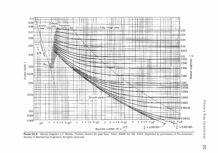
Pressure Drop Calculations
273
FIGURE 11.1 Moody Diagram, L.F. Moody, “Friction factors for pipe fl ow,” Trans. ASME Vol. 66. 1944. Reprinted by permission of The American Society of Mechanical Engineers. All rights reserved.
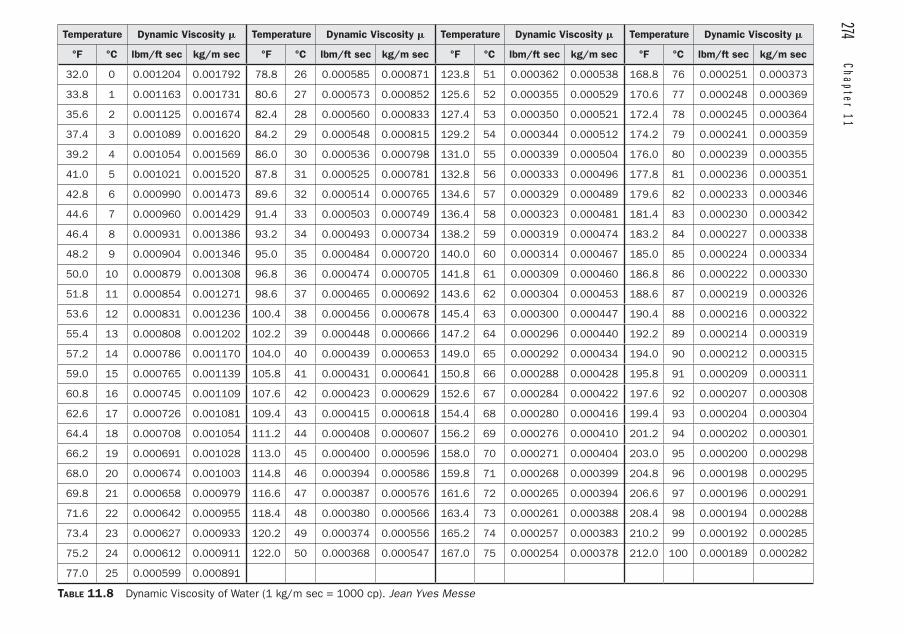
274 Chapter 11
Temperature Dynamic Viscosity � Temperature Dynamic Viscosity � Temperature Dynamic Viscosity � Temperature Dynamic Viscosity �
°F °C lbm/ft sec kg/m sec °F °C lbm/ft sec kg/m sec °F °C lbm/ft sec kg/m sec °F °C lbm/ft sec kg/m sec
32.0 0 0.001204 0.001792 78.8 26 0.000585 0.000871 123.8 51 0.000362 0.000538 168.8 76 0.000251 0.000373
33.8 1 0.001163 0.001731 80.6 27 0.000573 0.000852 125.6 52 0.000355 0.000529 170.6 77 0.000248 0.000369
35.6 2 0.001125 0.001674 82.4 28 0.000560 0.000833 127.4 53 0.000350 0.000521 172.4 78 0.000245 0.000364
37.4 3 0.001089 0.001620 84.2 29 0.000548 0.000815 129.2 54 0.000344 0.000512 174.2 79 0.000241 0.000359
39.2 4 0.001054 0.001569 86.0 30 0.000536 0.000798 131.0 55 0.000339 0.000504 176.0 80 0.000239 0.000355
41.0 5 0.001021 0.001520 87.8 31 0.000525 0.000781 132.8 56 0.000333 0.000496 177.8 81 0.000236 0.000351
42.8 6 0.000990 0.001473 89.6 32 0.000514 0.000765 134.6 57 0.000329 0.000489 179.6 82 0.000233 0.000346
44.6 7 0.000960 0.001429 91.4 33 0.000503 0.000749 136.4 58 0.000323 0.000481 181.4 83 0.000230 0.000342
46.4 8 0.000931 0.001386 93.2 34 0.000493 0.000734 138.2 59 0.000319 0.000474 183.2 84 0.000227 0.000338
48.2 9 0.000904 0.001346 95.0 35 0.000484 0.000720 140.0 60 0.000314 0.000467 185.0 85 0.000224 0.000334
50.0 10 0.000879 0.001308 96.8 36 0.000474 0.000705 141.8 61 0.000309 0.000460 186.8 86 0.000222 0.000330
51.8 11 0.000854 0.001271 98.6 37 0.000465 0.000692 143.6 62 0.000304 0.000453 188.6 87 0.000219 0.000326
53.6 12 0.000831 0.001236 100.4 38 0.000456 0.000678 145.4 63 0.000300 0.000447 190.4 88 0.000216 0.000322
55.4 13 0.000808 0.001202 102.2 39 0.000448 0.000666 147.2 64 0.000296 0.000440 192.2 89 0.000214 0.000319
57.2 14 0.000786 0.001170 104.0 40 0.000439 0.000653 149.0 65 0.000292 0.000434 194.0 90 0.000212 0.000315
59.0 15 0.000765 0.001139 105.8 41 0.000431 0.000641 150.8 66 0.000288 0.000428 195.8 91 0.000209 0.000311
60.8 16 0.000745 0.001109 107.6 42 0.000423 0.000629 152.6 67 0.000284 0.000422 197.6 92 0.000207 0.000308
62.6 17 0.000726 0.001081 109.4 43 0.000415 0.000618 154.4 68 0.000280 0.000416 199.4 93 0.000204 0.000304
64.4 18 0.000708 0.001054 111.2 44 0.000408 0.000607 156.2 69 0.000276 0.000410 201.2 94 0.000202 0.000301
66.2 19 0.000691 0.001028 113.0 45 0.000400 0.000596 158.0 70 0.000271 0.000404 203.0 95 0.000200 0.000298
68.0 20 0.000674 0.001003 114.8 46 0.000394 0.000586 159.8 71 0.000268 0.000399 204.8 96 0.000198 0.000295
69.8 21 0.000658 0.000979 116.6 47 0.000387 0.000576 161.6 72 0.000265 0.000394 206.6 97 0.000196 0.000291
71.6 22 0.000642 0.000955 118.4 48 0.000380 0.000566 163.4 73 0.000261 0.000388 208.4 98 0.000194 0.000288
73.4 23 0.000627 0.000933 120.2 49 0.000374 0.000556 165.2 74 0.000257 0.000383 210.2 99 0.000192 0.000285
75.2 24 0.000612 0.000911 122.0 50 0.000368 0.000547 167.0 75 0.000254 0.000378 212.0 100 0.000189 0.000282
77.0 25 0.000599 0.000891
TABLE 11.8 Dynamic Viscosity of Water (1 kg/m sec = 1000 cp). Jean Yves Messe
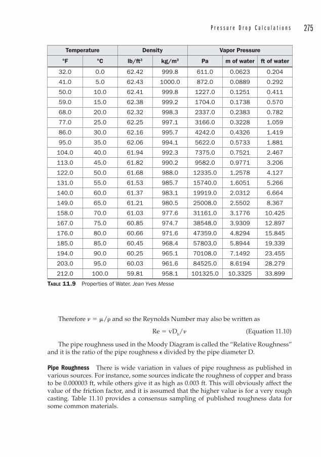
P r e s s u r e D r o p C a l c u l a t i o n s 275
Therefore � � �/� and so the Reynolds Number may also be writt en as
Re � vDh/� (Equation 11.10)
The pipe roughness used in the Moody Diagram is called the “Re lative Roughness” and it is the ra tio of the pipe roughness � divided by the pipe diameter D.
Pipe Roughness There is wide var iation in values of pipe roughness as published in various sources. For instance, some sources indicate the roughness of copper and brass to be 0.000003 ft, while others give it as high as 0.003 ft. This will obviously affect the value of the friction factor, and it is assumed that the higher value is for a very rough casting. Table 11.10 provides a consensus sampling of published roughness data for some common materials.
Temperature Density Vapor Pressure
°F °C lb/ft3 kg/m3 Pa m of water ft of water
32.0 0.0 62.42 999.8 611.0 0.0623 0.204
41.0 5.0 62.43 1000.0 872.0 0.0889 0.292
50.0 10.0 62.41 999.8 1227.0 0.1251 0.411
59.0 15.0 62.38 999.2 1704.0 0.1738 0.570
68.0 20.0 62.32 998.3 2337.0 0.2383 0.782
77.0 25.0 62.25 997.1 3166.0 0.3228 1.059
86.0 30.0 62.16 995.7 4242.0 0.4326 1.419
95.0 35.0 62.06 994.1 5622.0 0.5733 1.881
104.0 40.0 61.94 992.3 7375.0 0.7521 2.467
113.0 45.0 61.82 990.2 9582.0 0.9771 3.206
122.0 50.0 61.68 988.0 12335.0 1.2578 4.127
131.0 55.0 61.53 985.7 15740.0 1.6051 5.266
140.0 60.0 61.37 983.1 19919.0 2.0312 6.664
149.0 65.0 61.21 980.5 25008.0 2.5502 8.367
158.0 70.0 61.03 977.6 31161.0 3.1776 10.425
167.0 75.0 60.85 974.7 38548.0 3.9309 12.897
176.0 80.0 60.66 971.6 47359.0 4.8294 15.845
185.0 85.0 60.45 968.4 57803.0 5.8944 19.339
194.0 90.0 60.25 965.1 70108.0 7.1492 23.455
203.0 95.0 60.03 961.6 84525.0 8.6194 28.279
212.0 100.0 59.81 958.1 101325.0 10.3325 33.899
TABLE 11.9 Properties of Water. Jean Yves Messe
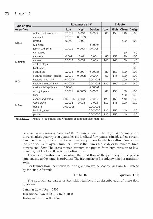
276 C h a p t e r 1 1
Laminar Flow, Turbulent Flow, and the Transiti on Zone The Reynolds Numb er is a dimensionles s quantity that quantifies the localized flow patterns inside a flow stream. Laminar flow is the term used to describe flow patterns in which localized flow within the pipe occurs in layers. Turbulent flow is the term used to describe random three-dimensional flow. The gross motion through the pipe is from high-pressure to low-pressure, but the local flow is multi-directional.
There is a transition zone in which the fluid flow at the periphery of the pipe is laminar, and at the center is turbulent. The friction factor f is unknown in this transition zone.
For laminar flow, the friction factor is given not by the Moody Diagram, but instead by t he simple formula
f � 64/Re (Equation 11.11)
The approximate values of Reynolds Numbers that describe each of these flow types are:
Laminar fl ow if Re � 2300Transitional fl ow if 2300 � Re � 4000Turbulent fl ow if 4000 � Re
Type of pipe or surface
Roughness � [ft] C-Factor
Low High Design Low High Clean Design
STEEL
welded and seamless 0.0001 0.008 0.0002 80 150 140 100
corroded 0.0005 0.0133
riveted 0.003 0.03 139 100
Stainless 0.00005
galvanized, plain 0.0002 0.0008 0.0005
corrugated 60 60
MINERAL
concrete 0.001 0.01 0.004 85 152 120 100
cement 0.0013 0.004 0.003 140 160 150 140
vitrified clays 110
brick sewer 100
IRON
cast, plain 0.0004 0.0027 0.00085 80 150 130 100
cast, tar (asphalt) coated 0.0002 0.0008 0.0004 50 145 130 100
cast, cement lined 0.000008 0.000008 150 140
cast, bituminous lined 0.000008 0.000008 130 160 148 140
cast, centrifugally spun 0.00001 0.00001
wrought, plain 0.0001 0.0003 0.0002 80 150 130 100
MISC.
fiber 150 140
copper and brass 0.000005 0.003 0.000005 120 150 140 130
wood stave 0.0006 0.003 0.002 110 145 120 110
transite 0.000008 0.000008
lead, tin, glass 0.000005 120 150 140 130
plastic 0.000005 120 150 140 130
TABLE 11.10 Absolute roughness and C-factors of common pipe materials.
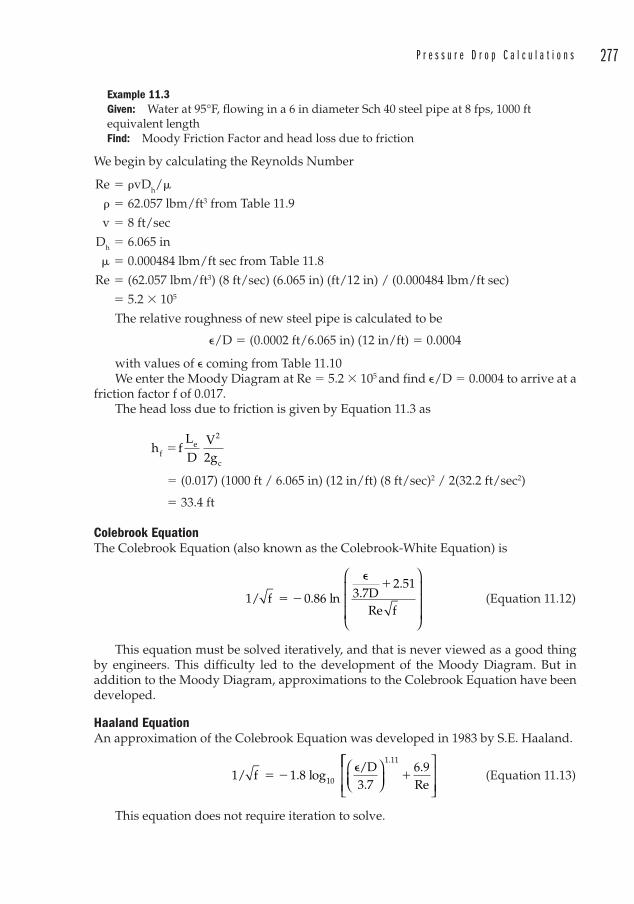
P r e s s u r e D r o p C a l c u l a t i o n s 277
Example 11.3Given: Water at 95°F, flowing in a 6 in diameter Sch 40 steel pipe at 8 fps, 1000 ft equivalent lengthFind: Moody Friction Factor and head loss due to friction
We begin by calculating the Reynolds Number
Re � �vDh/�
� � 62.057 lbm/ft3 from Table 11.9
v � 8 ft/sec
Dh � 6.065 in
� � 0.000484 lbm/ft sec from Table 11.8
Re � (62.057 lbm/ft3) (8 ft/sec) (6.065 in) (ft/12 in) / (0.000484 lbm/ft sec)
� 5.2 � 105
The relative roughness of new steel pipe is calculated to be
�/D � (0.0002 ft/6.065 in) (12 in/ft) � 0.0004
with values of � coming from Table 11.10We enter the Moody Diagram at Re � 5.2 � 105 and find �/D � 0.0004 to arrive at a
friction factor f of 0.017.The head loss due to friction is given by Equation 11.3 as
h f
LD
V2gf
e2
c
�
� (0.017) (1000 ft / 6.065 in) (12 in/ft) (8 ft/sec)2 / 2(32.2 ft/sec2)
� 33.4 ft
Colebrook Equation The Colebrook Equation (also known as the Colebrook-White Equation) is
1/ f 0.86 ln 3.7Df
� �
��2 51.
Re
⎛
⎝
⎜⎜⎜
⎞
⎠
⎟⎟⎟
(Equation 11.12)
This equation must be solved iteratively, and that is never viewed as a good thing by engineers. This difficulty led to the development of the Moody Diagram. But in addition to the Moody Diagram, approximations to the Colebrook Equation have been developed.
Haaland EquationAn a pproximation of the Colebrook Equation was developed in 1983 by S.E. Haaland.
1/ f 1.8 log/D3.7
6.9Re10 � �
� �
⎛⎝⎜
⎞⎠⎟
1 11.⎡⎡
⎣⎢⎢
⎤
⎦⎥⎥
(Equation 11.13)
This equation does not require iteration to solve.
278 C h a p t e r 1 1
Swamee-Jain EquationThe Swam ee-Jain Equation is anoth er approximation of the Colebrook Equation. It prov ides an accuracy within 1 percent of the Colebrook equation for relative roughnesses between 0.000001 and 0.01, and Reynolds Numbers between 5000 and 108.
f
log/D3.7
5.74Re10 0.9
� �
�
0 25.
⎛⎝⎜
⎞⎠⎟
⎡
⎣⎢
⎤
⎦⎥
22
(Equation 11.14)
Serghide’s SolutionAn even cl oser approximation (within 0.003 percent) to the Colebrook Equation is given by Serghide’s Solution.
f A
(B A)C 2B A
2 2
� � �
� �
�⎛
⎝⎜⎞
⎠⎟ ( Equation 11.15)
where
A � –2 log10
��
/D3.7
12Re
⎛⎝⎜
⎞⎠⎟
(Equation 11.16)
B � –2 log10
�
�D3.7
2.51 ARe
⎛
⎝
⎜⎜⎜
⎞
⎠
⎟⎟⎟
(Equation 11.17)
C � –2 log10
��
/D3.7
2.51 BRe
⎛⎝⎜
⎞⎠⎟
(Equation 11.18)
Hazen-Williams FormulaThe Hazen-Williams Formula for calculating head loss due to friction applies to the following conditions:
• Fluids with Kinematic Viscosity approximately 1.2 � 10–5 ft2/sec. This matches the viscosity of water at 60°F (15.6°C)
• Turbulent flow conditions
• “Moderate” temperatures
The Hazen-Williams Equation for head loss is
h
C L Q
C Dff
1.852
1.852 4.87�
(Equation 11.19)
where
Cf � Unit Conversion Factor [4.72 for Imperial units; 10.67 for SI units] L � Equivalent Length of pipe [ft or m] Q � Flow rate [ft3/sec or m3/sec] C � Hazen-Williams C-Factor D � Inside diameter [ft or m]
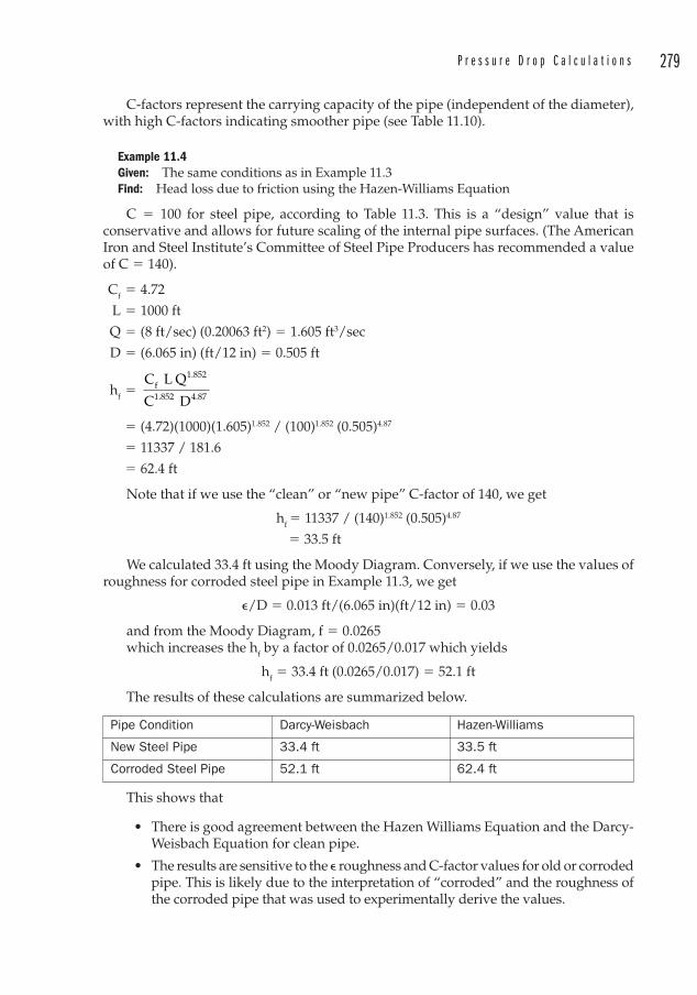
P r e s s u r e D r o p C a l c u l a t i o n s 279
C-factors represent the carrying capacity of the pipe (independent of the diameter), with high C-factors indicating smoother pipe (see Table 11.10).
Example 11.4Given: The same conditions as in Example 11.3Find: Head loss due to friction using the Hazen-Williams Equation
C � 100 for steel pipe, according to Table 11.3. This is a “design” value that is conservative and allows for future scaling of the internal pipe surfaces. (The American Iron and Steel Institute’s Committee of Steel Pipe Producers has recommended a value of C � 140).
Cf � 4.72
L � 1000 ft
Q � (8 ft/sec) (0.20063 ft2) � 1.605 ft3/sec
D � (6.065 in) (ft/12 in) � 0.505 ft
hf �
C L Q
C Df
1.852
1.852 4.87
� (4.72)(1000)(1.605)1.852 / (100)1.852 (0.505)4.87
� 11337 / 181.6
� 62.4 ft
Note that if we use the “clean” or “new pipe” C-factor of 140, we get
hf � 11 337 / (140)1.852 (0.505)4.87
� 33.5 ft
We calculated 33.4 ft using the Moody Diagram. Conversely, if we use the values of roughness for corroded steel pipe in Example 11.3, we get
�/D � 0.013 ft/(6.065 in)(ft/12 in) � 0.03
and from the Moody Diagram, f � 0.0265which incr eases the hf by a factor of 0.0265/0.017 which yields
hf � 33.4 ft (0.0265/0.017) � 52.1 ft
The results of these calculations are summarized below.
Pipe Condition Darcy-Weisbach Hazen-Williams
New Steel Pipe 33.4 ft 33.5 ft
Corroded Steel Pipe 52.1 ft 62.4 ft
This shows that
• There is good agreement between the Hazen Williams Equation and the Darcy-Weisbach Equation for clean pipe.
• The results are sensitive to the � roughness and C-factor values for old or corroded pipe. This is likely due to the interpretation of “corroded” and the roughness of the corroded pipe that was used to experimentally derive the values.
280 C h a p t e r 1 1
Fanning Friction Factor Occasionally one will encounter the Fanning Friction Factor , although its use is far less common than the Moody Friction Factor.
The Fanning Equation for friction uses the “Hydraulic Radius, ” defined as the cross sectional area of flow divided by the wetted perimeter. Thus,
Rh � A/U (Equation 11.20)where
Rh � Hydraulic Radius [ft or m] A � Cross sectional area [ft2 or m2] U � Wetted Perimeter [ft or m]
The Fanning head loss is given as
h f
LR
V2gf f
h
2
c
�⎛
⎝⎜⎞
⎠⎟⎛
⎝⎜⎞
⎠⎟ (Equation 11.21)
where
ff � Fanning Friction Factor [ dimensionless]
This is similar to the friction head loss calculation used by the more common Darcy-Weisbach Equation, and by cancelling out terms
h fLD
v2g
fL
Rv
fe
2
cf
h
2
� �⎛⎝⎜
⎞⎠⎟
⎛
⎝⎜⎞
⎠⎟⎛
⎝⎜⎞
⎠⎟ 22gc
⎛
⎝⎜⎞
⎠⎟ we see that
f/D � ff/Rh and Dh � D for full-pipe fl owf � ff (Dh/Rh) � ff (4A/U)/(A/U) � 4ff
Therefore, the Darcy Friction Factor is fo ur times the Fanning Friction Factor.
Tabulated or Graphic SolutionsBy now it is clear that there are multiple routes to our final destination of solving pressure drops. We indicated earlier that there are some shortcuts available for common problems, and that is indeed fortunate since the methods described above, while satisfactory, are mathematically complicated.
Tabulated values are available for water, air, and low-pressure natural gas. Once the equivalent length is determined, the friction loss is read from the tables and multiplied by the appropriate factor to give the friction loss. Linear interpolation must be used to determine losses at flow rates between tabulated values. This interpolation may be eliminated through the use of graphs that chart the relationships between flow rate and head loss. Some practical graphs are provided in the Appendix. These graphs are for asphalt-coated cast iron and various weights of steel pipe.
Note that manufacturers of other pipe materials can supply similar pressure drop data.
Minor LossesMinor losses are those friction losses attributed to fittings, valves, and entrance and exit losses. Minor losses may be determined with any of three methods:
• Resistance Coefficient K• E qu ivalent Length Metho d• Flow Coefficient Cv
P r e s s u r e D r o p C a l c u l a t i o n s 281
All other things being equal, the easiest method is the equivalent length method. However, equivalent length data are often not available for the components you need and conversions are necessary.
Resistance Coefficient KFlo w resistance data are available for a number of valves and fittings, although the user should be aware that significant variation may exist between data published by different sources. For critical applications, the valve or fitting manufacturer should be contacted for data specific to the item.
The friction head loss through fittings for which the resistance coefficient K is kn own is
hf � K (V2/2 gc) (Equation 11.22)
with V2/2gc being the velocity head through the fitting. See Table 11.11 for Resistance Coefficient data for common valves and fittings.
There is little difference in the K value s of different schedules of pipe fittings. Therefore, it is sufficient to use the data for Schedule 40 pipe. Sizes larger than 24-in diameter can be estimated using the K values for 24 in.
ReducersThe p ressure drop literature is full of time-consuming equations that relate head loss to the angle of the reducer walls. While no one can be faulted for performing these equations and including them in the total loss calculations, the head loss through a single reducer is not significant.
Unless your system contains many, many reducers, a faster and more practical approach is simply to include the length of the reducer among the equivalent lengths of the smaller of the two diameters.
Equivalent Length Metho dSince friction losses distill down to units of feet or meters, conversions have been developed to describe minor losses simply as an equivalent length of straight pipe. The lengths for a given diameter are summed.
If tables exist for friction losses (as they do for water and air), the total equivalent length is multiplied by the factor in the table to yield the friction loss for that particular diameter. The equivalent length is given by
L � KD/f (Equation 11.23)
where
K � Res istance Coefficient
D � I nside pipe diameter [ft]
f � Friction factor in the turbulent flow region
Otherwise, the equivalent length is used in the Darcy-Weisbach Equation with the friction factor f taken from the Moody Diagram.
This is a very convenient method, as it requires no extra step in the calculation. Data exists for many common fittings and valves. See Table 11.12.
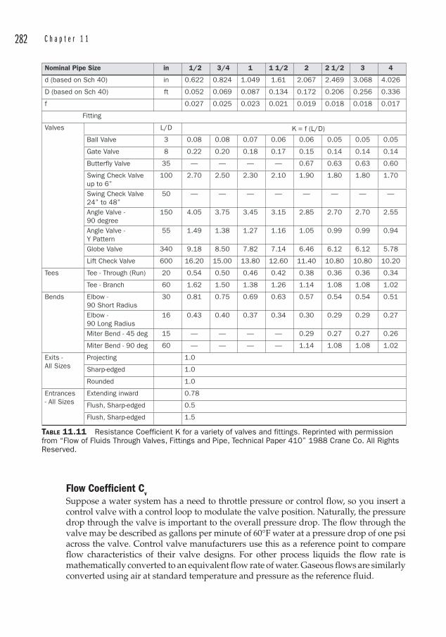
282 C h a p t e r 1 1
TABLE 11.11 Resistance Coefficient K for a variety of valves and fittings. Reprinted with permission from “Flow of Fluids Through Valves, Fittings and Pipe, Technical Paper 410” 1988 Crane Co. All Rights Reserved.
Nominal Pipe Size in 1/2 3/4 1 1 1/2 2 2 1/2 3 4
d (based on Sch 40) in 0.622 0.824 1.049 1.61 2.067 2.469 3.068 4.026
D (based on Sch 40) ft 0.052 0.069 0.087 0.134 0.172 0.206 0.256 0.336
f 0.027 0.025 0.023 0.021 0.019 0.018 0.018 0.017
Fitting
Valves L/D
Ball Valve 3 0.08 0.08 0.07 0.06 0.06 0.05 0.05 0.05
Gate Valve 8 0.22 0.20 0.18 0.17 0.15 0.14 0.14 0.14
Butterfly Valve 35 — — — — 0.67 0.63 0.63 0.60
Swing Check Valve up to 6”
100 2.70 2.50 2.30 2.10 1.90 1.80 1.80 1.70
Swing Check Valve 24” to 48”
50 — — — — — — — —
Angle Valve - 90 degree
150 4.05 3.75 3.45 3.15 2.85 2.70 2.70 2.55
Angle Valve - Y Pattern
55 1.49 1.38 1.27 1.16 1.05 0.99 0.99 0.94
Globe Valve 340 9.18 8.50 7.82 7.14 6.46 6.12 6.12 5.78
Lift Check Valve 600 16.20 15.00 13.80 12.60 11.40 10.80 10.80 10.20
Tees Tee - Through (Run) 20 0.54 0.50 0.46 0.42 0.38 0.36 0.36 0.34
Tee - Branch 60 1.62 1.50 1.38 1.26 1.14 1.08 1.08 1.02
Bends Elbow - 90 Short Radius
30 0.81 0.75 0.69 0.63 0.57 0.54 0.54 0.51
Elbow - 90 Long Radius
16 0.43 0.40 0.37 0.34 0.30 0.29 0.29 0.27
Miter Bend - 45 deg 15 — — — — 0.29 0.27 0.27 0.26
Miter Bend - 90 deg 60 — — — — 1.14 1.08 1.08 1.02
Exits - All Sizes
Projecting 1.0
Sharp-edged 1.0
Rounded 1.0
Entrances- All Sizes
Extending inward 0.78
Flush, Sharp-edged 0.5
Flush, Sharp-edged 1.5
K = f (L/D)
Flow Coefficient CvS upp ose a water system has a need to throttle pressure or control flow, so you insert a control valve with a control loop to modulate the valve position. Naturally, the pressure drop through the valve is important to the overall pressure drop. The flow through the valve may be described as gallons per minute of 60°F water at a pressure drop of one psi across the valve. Control valve manufacturers use this as a reference point to compare flow characteristics of their valve designs. For other process liquids the flow rate is mathematically converted to an equivalent flow rate of water. Gaseous flows are similarly converted using air at standard temperature and pressure as the reference fluid.
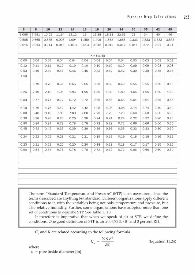
P r e s s u r e D r o p C a l c u l a t i o n s 283
6 8 10 12 14 16 18 20 24 30 36 42 48
6.065 7.981 10.02 11.94 13.12 15 16.88 18.81 22.63 28 34 40 46
0.505 0.665 0.835 0.995 1.094 1.250 1.406 1.568 1.886 2.333 2.833 3.333 3.833
0.015 0.014 0.014 0.013 0.013 0.013 0.012 0.012 0.012 0.011 0.011 0.01 0.01
K = f (L/D)
0.05 0.04 0.04 0.04 0.04 0.04 0.04 0.04 0.04 0.03 0.03 0.03 0.03
0.12 0.11 0.11 0.10 0.10 0.10 0.10 0.10 0.10 0.09 0.09 0.08 0.08
0.53 0.49 0.49 0.46 0.46 0.46 0.42 0.42 0.42 0.39 0.39 0.35 0.35
1.50 — — — — — — — — — — — —
— 0.70 0.70 0.65 0.65 0.65 0.60 0.60 0.60 0.55 0.55 0.50 0.50
2.25 2.10 2.10 1.95 1.95 1.95 1.80 1.80 1.80 1.65 1.65 1.50 1.50
0.83 0.77 0.77 0.72 0.72 0.72 0.66 0.66 0.66 0.61 0.61 0.55 0.55
5.10 4.76 4.76 4.42 4.42 4.42 4.08 4.08 4.08 3.74 3.74 3.40 3.40
9.00 8.40 8.40 7.80 7.80 7.80 7.20 7.20 7.20 6.60 6.60 6.00 6.00
0.30 0.28 0.28 0.26 0.26 0.26 0.24 0.24 0.24 0.22 0.22 0.20 0.20
0.90 0.84 0.84 0.78 0.78 0.78 0.72 0.72 0.72 0.66 0.66 0.60 0.60
0.45 0.42 0.42 0.39 0.39 0.39 0.36 0.36 0.36 0.33 0.33 0.30 0.30
0.24 0.22 0.22 0.21 0.21 0.21 0.19 0.19 0.19 0.18 0.18 0.16 0.16
0.23 0.21 0.21 0.20 0.20 0.20 0.18 0.18 0.18 0.17 0.17 0.15 0.15
0.90 0.84 0.84 0.78 0.78 0.78 0.72 0.72 0.72 0.66 0.66 0.60 0.60
The term “Standard Temperature and Pressure” (STP ) is an oxymoron, since the terms described are anything but standard. Different organizations apply different conditions to it, with the variables being not only temperature and pressure, but also relative humidity. Further, some organizations have adopted more than one set of conditions to describe STP. See Table 11.13.
It therefore is imperative that when we speak of air at STP, we define the conditions. One good definition of STP is air at 0.075 lb/ft3 and 0 percent RH.
Cv and K are r elated according to the following formula
C
29.9 d
Kv
2
�
(Equation 11.24)where
d � pipe inside diameter [in]
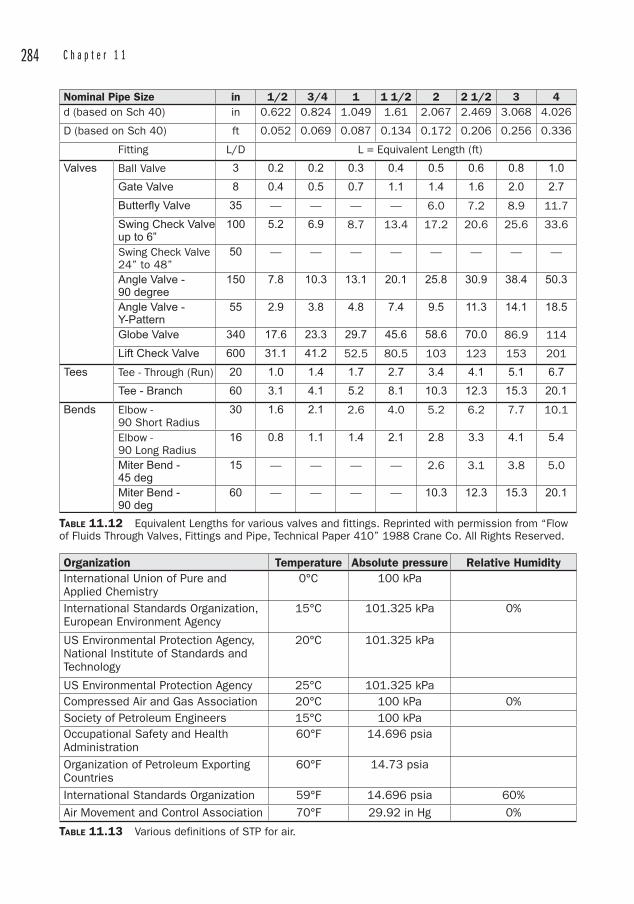
284 C h a p t e r 1 1
TABLE 11.12 Equivalent Lengths for various valves and fittings. Reprinted with permission from “Flow of Fluids Through Valves, Fittings and Pipe, Technical Paper 410” 1988 Crane Co. All Rights Reserved.
Nominal Pipe Size in 1/2 3/4 1 1 1/2 2 2 1/2 3 4d (based on Sch 40) in 0.622 0.824 1.049 1.61 2.067 2.469 3.068 4.026
D (based on Sch 40) ft 0.052 0.069 0.087 0.134 0.172 0.206 0.256 0.336
Fitting L/D L = Equivalent Length (ft)
Valves Ball Valve 3 0.2 0.2 0.3 0.4 0.5 0.6 0.8 1.0
Gate Valve 8 0.4 0.5 0.7 1.1 1.4 1.6 2.0 2.7
Butterfly Valve 35 — — — — 6.0 7.2 8.9 11.7
Swing Check Valve up to 6”
100 5.2 6.9 8.7 13.4 17.2 20.6 25.6 33.6
Swing Check Valve 24” to 48”
50 — — — — — — — —
Angle Valve - 90 degree
150 7.8 10.3 13.1 20.1 25.8 30.9 38.4 50.3
Angle Valve - Y-Pattern
55 2.9 3.8 4.8 7.4 9.5 11.3 14.1 18.5
Globe Valve 340 17.6 23.3 29.7 45.6 58.6 70.0 86.9 114
Lift Check Valve 600 31.1 41.2 52.5 80.5 103 123 153 201
Tees Tee - Through (Run) 20 1.0 1.4 1.7 2.7 3.4 4.1 5.1 6.7
Tee - Branch 60 3.1 4.1 5.2 8.1 10.3 12.3 15.3 20.1
Bends Elbow - 90 Short Radius
30 1.6 2.1 2.6 4.0 5.2 6.2 7.7 10.1
Elbow - 90 Long Radius
16 0.8 1.1 1.4 2.1 2.8 3.3 4.1 5.4
Miter Bend - 45 deg
15 — — — — 2.6 3.1 3.8 5.0
Miter Bend - 90 deg
60 — — — — 10.3 12.3 15.3 20.1
Organization Temperature Absolute pressure Relative HumidityInternational Union of Pure and Applied Chemistry
0°C 100 kPa
International Standards Organization, European Environment Agency
15°C 101.325 kPa 0%
US Environmental Protection Agency, National Institute of Standards and Technology
20°C 101.325 kPa
US Environmental Protection Agency 25°C 101.325 kPaCompressed Air and Gas Association 20°C 100 kPa 0%Society of Petroleum Engineers 15°C 100 kPaOccupational Safety and Health Administration
60°F 14.696 psia
Organization of Petroleum Exporting Countries
60°F 14.73 psia
International Standards Organization 59°F 14.696 psia 60%
Air Movement and Control Association 70°F 29.92 in Hg 0%
TABLE 11.13 Various definitions of STP for air.
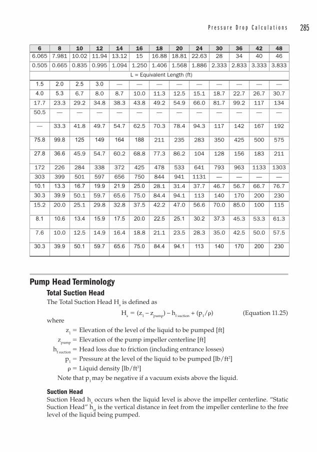
P r e s s u r e D r o p C a l c u l a t i o n s 285
Pump Head TerminologyTotal Suction HeadThe Tot al Suction Head Hs is d efined as
Hs � (z1 – zpump) – hf suction + (p1/�) (Equation 11.25)where
z1 � Elevation of the level of the liquid to be pumped [ft]
zpump � Elevation of the pump impeller centerline [ft]
hf suction � Head loss due to friction (including entrance losses)
p1 � Pressure at the level of the liquid to be pumped [lb/ft2]
� � Liquid density [lb/ft3]
Note that p1 may be negative if a vacuum exists above the liquid.
Suction HeadSuction Head hs occu rs when the liquid level is above the impeller centerline. “Static Suction Head” hst is the vertical distance in feet from the impeller centerline to the free level of the liquid being pumped.
6 8 10 12 14 16 18 20 24 30 36 42 486.065 7.981 10.02 11.94 13.12 15 16.88 18.81 22.63 28 34 40 46
0.505 0.665 0.835 0.995 1.094 1.250 1.406 1.568 1.886 2.333 2.833 3.333 3.833
L = Equivalent Length (ft)
1.5 2.0 2.5 3.0 — — — — — — — — —
4.0 5.3 6.7 8.0 8.7 10.0 11.3 12.5 15.1 18.7 22.7 26.7 30.7
17.7 23.3 29.2 34.8 38.3 43.8 49.2 54.9 66.0 81.7 99.2 117 134
50.5 — — — — — — — — — — — —
— 33.3 41.8 49.7 54.7 62.5 70.3 78.4 94.3 117 142 167 192
75.8 99.8 125 149 164 188 211 235 283 350 425 500 575
27.8 36.6 45.9 54.7 60.2 68.8 77.3 86.2 104 128 156 183 211
172 226 284 338 372 425 478 533 641 793 963 1133 1303
303 399 501 597 656 750 844 941 1131 — — — —
10.1 13.3 16.7 19.9 21.9 25.0 28.1 31.4 37.7 46.7 56.7 66.7 76.7
30.3 39.9 50.1 59.7 65.6 75.0 84.4 94.1 113 140 170 200 230
15.2 20.0 25.1 29.8 32.8 37.5 42.2 47.0 56.6 70.0 85.0 100 115
8.1 10.6 13.4 15.9 17.5 20.0 22.5 25.1 30.2 37.3 45.3 53.3 61.3
7.6 10.0 12.5 14.9 16.4 18.8 21.1 23.5 28.3 35.0 42.5 50.0 57.5
30.3 39.9 50.1 59.7 65.6 75.0 84.4 94.1 113 140 170 200 230
286 C h a p t e r 1 1
Static Discharge HeadStatic Discharge Head is the vertical distance in feet from the pump centerline to the discharge point or the surface of the liquid in a discharge tank whose free level is above the discharge point.
Total Static HeadTotal Static Head is the vertical distance in feet between the free level of the liquid being pumped and the discharge point or the surface of the liquid in a discharge tank whose free level is above the discharge point.
Total Discharge HeadNot to be confused with Total Dynamic Head (which is commonly abbreviated TDH), the Total Discharge Head is defined as
Hd � (Static Discharge Head) + (hf discharge) + (p2/�), or
Hd � (z2 – zpump) + (hf discharge) + (p2/�) (Equation 11.26)where
hf discharge � Friction head losses in the discharge piping, including exit losses
p2 � Pressure at the discharge point [lb/ft2]
� � Liquid density [lb/ft3]
Total Dynamic HeadTotal Dynamic Head (TDH) is sometimes also known as the “Total System Head” or “Total Head”. The term TDH is more commonly used. It is the sum of the Total Discharge Head and the Total Suction Head. If a c ommon datum is used (for example, the impeller
Suction LiftSuction Lift occurs when the level of the liquid lies below the impeller centerline. This is a static lift condition. An equivalent suction lift condition occurs when there is no static lift (i.e. the liquid level is above the impeller centerline) but there is a vacuum above the liquid. In that case, the lift is equal to the static head minus the vacuum in feet. “Static Suction Lift” is the vertical distance in feet from the impeller centerline to the free level of the liquid being pumped.
When p1 starts out as atmospheric but changes to a vacuum, the results can be dramatic. Catastrophic tank failures have occurred due to improper venting of tanks during draw-down or pumping. This is often the result of a sheet of plastic having been placed over the vent during maintenance such as painting.
The vent is there to permit atmospheric air to enter the tank and displace the liquid that is removed from the tank. If the air is prevented from entering, a vacuum is produced over the liquid and in a short period of time atmospheric pressure acts on a large external tank area. This results in a tremendous force being applied to the external surface of the tank. Tanks are not designed for this condition and the shells buckle and often rupture. It takes only a thin sheet of polyethylene to create this very hazardous condition over a vent. Vents must be inspected after maintenance and during start-ups.
P r e s s u r e D r o p C a l c u l a t i o n s 287
centerline) and attention is paid to the signs of the elevations, then the TDH can be summed algebraically4. Thus
TDH � Hd � Hs (Equation 11.27)
� [(z2 � zpump) � hf discharge � p2/�] � [(z1 � zpump) � hf suction � p1/�]
� (z2 � z1) � (hf discharge � hf suction) � (p2 � p1)/� (Equation 11.28)
We recognize the similarities to Bernoulli’s Equation (Equation 11.4) and note that when:
• No head is extracted via a turbine
• The velocity heads may be ignored
Then
TDH � hA (Equation 11.29)
And in fact this is usually the case. For this reason, pump heads are normally specified according to the TDH.
Power RequirementsOnce the Total Dynamic Head is found, the power required to operate the pump can be determined. The “Theoretical Horsepower”, also called the “Hydraulic Horsepower” is defined as
Hydraulic HP � (lb of liquid per minute)(head in feet)/33,000
The actual horsepower required will be greater than the hydraulic horsepower, since the pump will be less than 100 percent efficient. In fact, the “Best Efficiency Point” or BEP of a centrifugal pump does not often exceed 85 percent. The BEP of a centrifugal pump is usually about 80 to 85 percent of the maximum head, or shut-off head.
The Brake Horsepower is defined as
BHP � (Hydraulic HP)/Pump Effi ciency
or
BHP
(GPM)(TDH)(SG)(3960)( )
��
(Equation 11.30)
where
GPM � Flow rate in GPM
TDH � Total Dynamic Head in ft
SG � Specific Gravity (dimensionless)
� � Pump Efficiency (dimensionless). A reasonable estimate for pump efficiency is 70 percent
4 Some references distinguish between a Suction Lift or a Suction Head condition in calculating the TDH, i.e., if there is a Suction Head condition (the liquid level is above the impeller centerline), then TDH � Hd � Hs and if there is a Suction Lift condition (the liquid level is below the impeller centerline), then TDH � Hd � Hs. This seems unnecessarily confusing. If the elevations are treated as positive or negative with respect to the datum, then this confusion can be avoided.
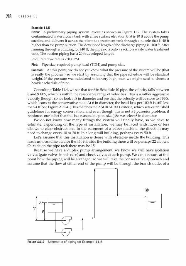
288 C h a p t e r 1 1
Example 11.5Given: A preliminary piping system layout as shown in Figure 11.2. The system takes contaminated water from a tank with a free surface elevation that is 10 ft above the pump suction, and delivers it across the plant to a treatment tank through a nozzle that is 40 ft higher than the pump suction. The developed length of the discharge piping is 1100 ft. After running through a building for 440 ft, the pipe exits onto a rack to a waste water treatment tank. The suction piping has a 20 ft developed length.
Required flow rate is 750 GPM.
Find: Pipe size, required pump head (TDH) and pump size.
Solution: At this point, we do not yet know what the pressure of the system will be (that is really the problem) so we start by assuming that the pipe schedule will be standard weight. If the pressure was calculated to be very high, then we might need to choose a heavier schedule of pipe.
Consulting Table 11.4, we see that for 6 in Schedule 40 pipe, the velocity falls between 8 and 9 FPS, which is within the reasonable range of velocities. This is a rather aggressive velocity though, so we look at 8 in diameter and see that the velocity will be close to 5 FPS, which leans to the conservative side. At 6 in diameter, the head loss per 100 ft is still less than 4 ft. See Figure A9.24. (This matches the ASHRAE 90.1 criteria, which sets established guidelines for energy conservation, and even though this is not a hydronics problem, it reinforces our belief that this is a reasonable pipe size.) So we select 6 in diameter.
We do not know how many fittings the system will finally have, so we have to estimate. Depending on the type of installation, we may be faced with more or less elbows to clear obstructions. In the basement of a paper machine, the direction may need to change every 10 or 20 ft. In a long mill building, perhaps every 50 ft.
Let’s assume that this installation is dense with obstacles inside the building. This leads us to assume that for the 440 ft inside the building there will be perhaps 22 elbows. Outside on the pipe rack there may be 15.
Because we have a duplex pump arrangement, we know we will have isolation valves (gate valves in this case) and check valves at each pump. We can’t be sure at this point how the piping will be arranged, so we will take the conservative approach and assume that the flow at either end of the pump will be through the branch outlet of a
FIGURE 11.2 Schematic of piping for Example 11.5.
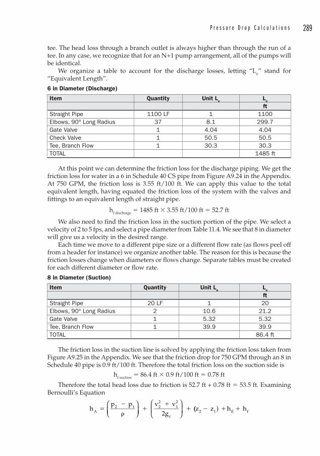
P r e s s u r e D r o p C a l c u l a t i o n s 289
tee. The head loss through a branch outlet is always higher than through the run of a tee. In any case, we recognize that for an N+1 pump arrangement, all of the pumps will be identical.
We organize a table to account for the discharge losses, letting “Le” stand for “Equivalent Length”.
6 in Di ameter (Discharge)
Item Quantity Unit Le Le
ftStraight Pipe 1100 LF 1 1100Elbows, 90° Long Radius 37 8.1 299.7Gate Valve 1 4.04 4.04Check Valve 1 50.5 50.5Tee, Branch Flow 1 30.3 30.3TOTAL 1485 ft
At this point we can determine the friction loss for the discharge piping. We get the friction loss for water in a 6 in Schedule 40 CS pipe from Figure A9.24 in the Appendix. At 750 GPM, the friction loss is 3.55 ft/100 ft. We can apply this value to the total equivalent length, having equated the friction loss of the system with the valves and fittings to an equivalent length of straight pipe.
hf discharge � 1485 ft � 3.55 ft/100 ft � 52.7 ft
We also need to find the friction loss in the suction portion of the pipe. We select a velocity of 2 to 5 fps, and select a pipe diameter from Table 11.4. We see that 8 in diameter will give us a velocity in the desired range.
Each time we move to a different pipe size or a different flow rate (as flows peel off from a header for instance) we organize another table. The reason for this is because the friction losses change when diameters or flows change. Separate tables must be created for each different diameter or flow rate.
8 in Diameter (Suction)
Item Quantity Unit Le Le
ftStraight Pipe 20 LF 1 20 Elbows, 90° Long Radius 2 10.6 21.2Gate Valve 1 5.32 5.32Tee, Branch Flow 1 39.9 39.9TOTAL 86.4 ft
The friction loss in the suction line is solved by applying the friction loss taken from Figure A9.25 in the Appendix. We see that the friction drop for 750 GPM through an 8 in Schedule 40 pipe is 0.9 ft/100 ft. Therefore the total friction loss on the suction side is
hf suction � 86.4 ft � 0.9 ft/100 ft � 0.78 ft
Therefore the total head loss due to friction is 52.7 ft + 0.78 ft � 53.5 ft. Examining Bernoulli’s Equation
hp p v v
2gA2 1 2
212
c
��
��
��
⎛⎝⎜
⎞⎠⎟
⎛
⎝⎜
⎞
⎠⎟ ((z z ) h h2 1 E f� � �
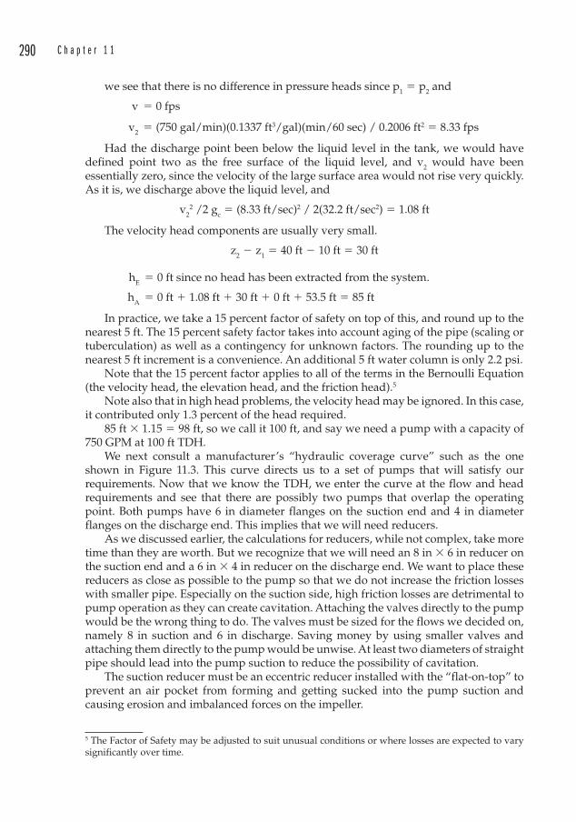
290 C h a p t e r 1 1
we see that there is no difference in pressure heads since p1 � p2 and
v � 0 fps
v2 � (750 gal/min)(0.1337 ft3/gal)(min/60 sec) / 0.2006 ft2 � 8.33 fps
Had the discharge point been below the liquid level in the tank, we would have defined point two as the free surface of the liquid level, and v2 would have been essentially zero, since the velocity of the large surface area would not rise very quickly. As it is, we discharge above the liquid level, and
v22 /2 gc � (8.33 ft/sec)2 / 2(32.2 ft/sec2) � 1.08 ft
The velocity head components are usually very small.
z2 � z1 � 40 ft � 10 ft � 30 ft
hE � 0 ft since no head has been extracted from the system.
hA � 0 ft � 1.08 ft � 30 ft � 0 ft � 53.5 ft � 85 ft
In practice, we take a 15 percent factor of safety on top of this, and round up to the nearest 5 ft. The 15 percent safety factor takes into account aging of the pipe (scaling or tuberculation) as well as a contingency for unknown factors. The rounding up to the nearest 5 ft increment is a convenience. An additional 5 ft water column is only 2.2 psi.
Note that the 15 percent factor applies to all of the terms in the Bernoulli Equation (the velocity head, the elevation head, and the friction head).5
Note also that in high head problems, the velocity head may be ignored. In this case, it contributed only 1.3 percent of the head required.
85 ft � 1.15 � 98 ft, so we call it 100 ft, and say we need a pump with a capacity of 750 GPM at 100 ft TDH.
We next consult a manufacturer’s “hydraulic coverage curve” such as the one shown in Figure 11.3. This curve directs us to a set of pumps that will satisfy our requirements. Now that we know the TDH, we enter the curve at the flow and head requirements and see that there are possibly two pumps that overlap the operating point. Both pumps have 6 in diameter flanges on the suction end and 4 in diameter flanges on the discharge end. This implies that we will need reducers.
As we discussed earlier, the calculations for reducers, while not complex, take more time than they are worth. But we recognize that we will need an 8 in � 6 in reducer on the suction end and a 6 in � 4 in reducer on the discharge end. We want to place these reducers as close as possible to the pump so that we do not increase the friction losses with smaller pipe. Especially on the suction side, high friction losses are detrimental to pump operation as they can create cavitation. Attaching the valves directly to the pump would be the wrong thing to do. The valves must be sized for the flows we decided on, namely 8 in suction and 6 in discharge. Saving money by using smaller valves and attaching them directly to the pump would be unwise. At least two diameters of straight pipe should lead into the pump suction to reduce the possibility of cavitation.
The suction reducer must be an eccentric reducer installed with the “flat-on-top” to prevent an air pocket from forming and getting sucked into the pump suction and causing erosion and imbalanced forces on the impeller.
5 The Factor of Safety may be adjusted to suit unusual conditions or where losses are expected to vary significantly over time.
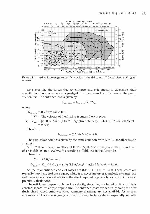
P r e s s u r e D r o p C a l c u l a t i o n s 291
Let’s examine the losses due to entrance and exit effects to determine their contribution. Let’s assume a sharp-edged, flush entrance from the tank to the pump suction line. The entrance loss is given by
hf entrance � Kentrance (V2/2gc)
where
Kentrance � 0.5 from Table 11.11
V2 � The velocity of the fluid as it enters the 8 in pipe.
v12 /2 gc � [(750 gal/min)(0.1337 ft3/gal)(min/60 sec)/0.3474 ft2]2 / 2(32.2 ft/sec2)
� 0.36 ft
Therefore,
hf entrance � (0.5) (0.36 ft) � 0.18 ft
The exit loss at point 2 is given by the same equation, with K � 1.0 for all exits and all sizes.
V2 � (750 gal/min)(min/60 sec)(0.1337 ft3/gal)/(0.20063 ft2), since the internal area of a 6 in Sch 40 line is 0.20063 ft2 according to Table A.1 in the Appendix.
Therefore
V2 � 8.3 ft/sec and
hf exit � Kexit (V2/2gc) � (1.0) (8.3 ft/sec)2/ (2)(32.2 ft/sec2) � 1.1 ft.
So the total entrance and exit losses are 0.36 ft + 1.1 ft � 1.5 ft. These losses are typically very low, and once again, while it is never incorrect to include entrance and exit losses in head loss calculations, the effort required is generally not worth it for most practical calculations.
The exit losses depend only on the velocity, since they are based on K and this is constant regardless of type or pipe size. The entrance losses are generally going to be for flush, sharp-edged entrances since commercial fittings are not available for smooth entrances, and no one is going to spend money to fabricate an especially smooth,
FIGURE 11.3 Hydraulic coverage curves for a typical industrial pump. ITT Goulds Pumps. All rights reserved.
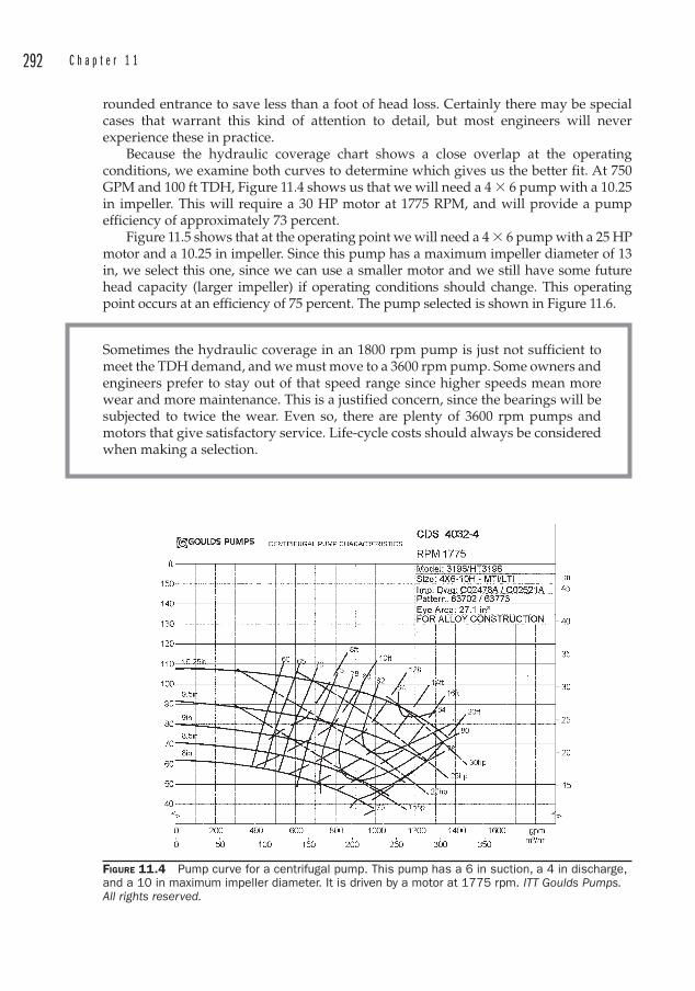
292 C h a p t e r 1 1
rounded entrance to save less than a foot of head loss. Certainly there may be special cases that warrant this kind of attention to detail, but most engineers will never experience these in practice.
Because the hydraulic coverage chart shows a close overlap at the operating conditions, we examine both curves to determine which gives us the better fit. At 750 GPM and 100 ft TDH, Figure 11.4 shows us that we will need a 4 � 6 pump with a 10.25 in impeller. This will require a 30 HP motor at 1775 RPM, and will provide a pump efficiency of approximately 73 percent.
Figure 11.5 shows that at the operating point we will need a 4 � 6 pump with a 25 HP motor and a 10.25 in impeller. Since this pump has a maximum impeller diameter of 13 in, we select this one, since we can use a smaller motor and we still have some future head capacity (larger impeller) if operating conditions should change. This operating point occurs at an efficiency of 75 percent. The pump selected is shown in Figure 11.6.
Sometimes the hydraulic coverage in an 1800 rpm pump is just not sufficient to meet the TDH demand, and we must move to a 3600 rpm pump. Some owners and engineers prefer to stay out of that speed range since higher speeds mean more wear and more maintenance. This is a justified concern, since the bearings will be subjected to twice the wear. Even so, there are plenty of 3600 rpm pumps and motors that give satisfactory service. Life-cycle costs should always be considered when making a selection.
FIGURE 11.4 Pump curve for a centrifugal pump. This pump has a 6 in suction, a 4 in discharge, and a 10 in maximum impeller diameter. It is driven by a motor at 1775 rpm. ITT Goulds Pumps. All rights reserved.
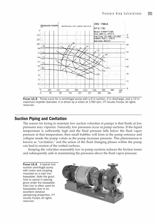
P r e s s u r e D r o p C a l c u l a t i o n s 293
FIGURE 11.5 Pump curve for a centrifugal pump with a 6 in suction, 4 in discharge, and a 13 in maximum impeller diameter. It is driven by a motor at 1780 rpm. ITT Goulds Pumps. All rights reserved.
FIGURE 11.6 A typical end suction centrifugal pump with motor and coupling mounted on a cast iron baseplate. Note the grout hole to assist in placing grout under the baseplate. Cast iron is often used for baseplates due to its excellent vibration dampening properties. ITTGoulds Pumps. All rights reserved.
Suction Piping and Cavitation The reason for trying to maintain low suction velocities at pumps is that fluids at low pressures may vaporize. Naturally, low pressures occur at pump suctions. If the liquid temperature is sufficiently high and the fluid pressure falls below the fluid vapor pressure at that temperature, then small bubbles will form at the pump entrance and collapse inside the pump volute as the pump increases pressure. This phenomenon is known as “cavitation,” and the action of the fluid changing phases within the pump can lead to erosion of the wetted surfaces.
Keeping the velocities reasonably low in pump suctions reduces the friction losses and subsequently aids in maintaining the pressures above the fluid vapor pressure.
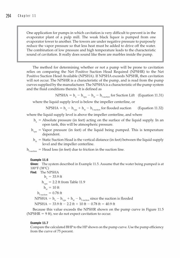
294 C h a p t e r 1 1
One application for pumps in which cavitation is very difficult to prevent is in the evaporator plant of a pulp mill. The weak black liquor is pumped from one evaporator tower to another. The towers are under negative pressure to purposely reduce the vapor pressure so that less heat must be added to drive off the water. The combination of low pressure and high temperature leads to the characteristic sound of cavitation. It really does sound like there are marbles inside the pump.
The method for determining whether or not a pump will be prone to cavitation relies on comparing the Net Positive Suction Head Required (NPSHR) to the Net Positive Suction Head Available (NPSHA). If NPSHA exceeds NPSHR, then cavitation will not occur. The NPSHR is a characteristic of the pump, and is read from the pump curves supplied by the manufacturer. The NPSHA is a characteristic of the pump system and the fluid conditions therein. It is defined as
NPSHA � ha � hvpa � hst � hf suction for Suction Lift (Equation 11.31)
where the liquid supply level is below the impeller centerline, or
NPSHA � ha � hvpa � hst � hf suction for fl ooded suction (Equation 11.32)
where the liquid supply level is above the impeller centerline, and where
ha � Absolute pressure (in feet) acting on the surface of the liquid supply. In an open tank, this will be atmospheric pressure.
hvpa � Vapor pressure (in feet) of the liquid being pumped. This is temperature
dependent.
hst � Static Suction Head is the vertical distance (in feet) between the liquid supply level and the impeller centerline.
hf suction � Head loss (in feet) due to friction in the suction line.
Example 11.6Given: The system described in Example 11.5. Assume that the water being pumped is at 100°F (38°C)Find: The NPSHA
ha � 33.9 ft
hvpa � 2.2 ft from Table 11.9
hst � 10 ft
hf suction � 0.78 ft
NPSHA � ha � hvpa � hst � hf suction since the suction is flooded
NPSHA � 33.9 ft � 2.2 ft � 10 ft � 0.78 ft � 40.9 ft
Because this value exceeds the NPSHR shown on the pump curve in Figure 11.5 (NPSHR � 9 ft), we do not expect cavitation to occur.
Example 11.7Compare the calculated BHP to the HP shown on the pump curve. Use the pump efficiency from the curve of 75 percent.
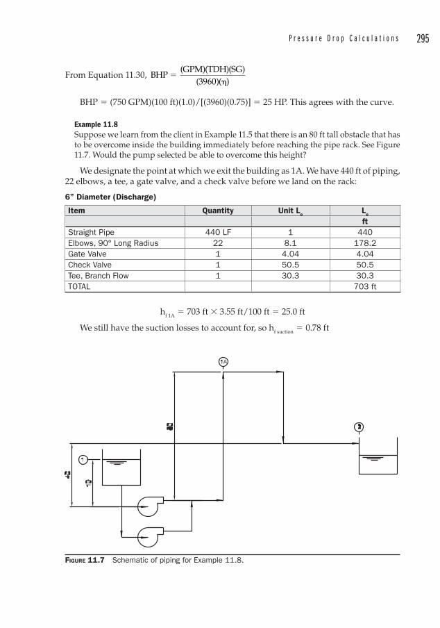
P r e s s u r e D r o p C a l c u l a t i o n s 295
From Equation 11.30, BHP
(GPM)(TDH)(SG)(3960)( )
��
BHP � (750 GPM)(100 ft)(1.0)/[(3960)(0.75)] � 25 HP. This agrees with the curve.
Example 11.8Suppose we learn from the client in Example 11.5 that there is an 80 ft tall obstacle that has to be overcome inside the building immediately before reaching the pipe rack. See Figure 11.7. Would the pump selected be able to overcome this height?
We designate the point at which we exit the building as 1A. We have 440 ft of piping, 22 elbows, a tee, a gate valve, and a check valve before we land on the rack:
6” Diameter (Discharge)
Item Quantity Unit Le Le
ftStraight Pipe 440 LF 1 440Elbows, 90° Long Radius 22 8.1 178.2Gate Valve 1 4.04 4.04Check Valve 1 50.5 50.5Tee, Branch Flow 1 30.3 30.3TOTAL 703 ft
hf 1A � 703 ft � 3.55 ft/100 ft � 25.0 ft
We still have the suction losses to account for, so hf suction � 0.78 ft
FIGURE 11.7 Schematic of piping for Example 11.8.
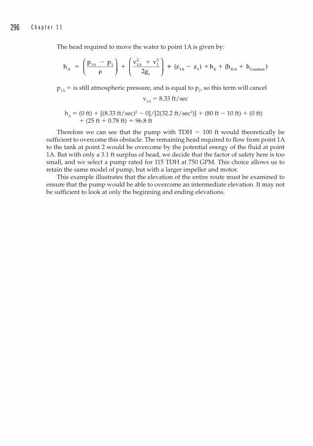
296 C h a p t e r 1 1
The head required to move the water to point 1A is given by:
hp p v v
2gA1A 1 1A
212
c
��
��
�⎛⎝⎜
⎞⎠⎟
⎛
⎝⎜
⎞
⎠⎟ �� � � � �(z z ) h (h h1A 1 E f1A f suction )
p1A � is still atmospheric pressure, and is equal to p1, so this term will cancel
v1A � 8.33 ft/sec
hA � (0 ft) � [(8.33 ft/sec)2 � 0]/[2(32.2 ft/sec2)] � (80 ft � 10 ft) � (0 ft)
� (25 ft � 0.78 ft) � 96.8 ft
Therefore we can see that the pump with TDH � 100 ft would theoretically be sufficient to overcome this obstacle. The remaining head required to flow from point 1A to the tank at point 2 would be overcome by the potential energy of the fluid at point 1A. But with only a 3.1 ft surplus of head, we decide that the factor of safety here is too small, and we select a pump rated for 115 TDH at 750 GPM. This choice allows us to retain the same model of pump, but with a larger impeller and motor.
This example illustrates that the elevation of the entire route must be examined to ensure that the pump would be able to overcome an intermediate elevation. It may not be sufficient to look at only the beginning and ending elevations.
297
CHAPTER 12Piping Project Anatomy
Depending on the size of a project, more or less preparation may be required. This preparation takes the form of a variety of engineering design tools that the piping engineer employs to build a project from a blank sheet of paper.
Simple projects may not require any of these tools. Large complex projects may require all of them. This chapter will explain how these design documents are used and developed.
A good place to start is by asking the question: “Why is engineering required at all?” One obvious answer is that for high pressure, dangerous, or critical systems, it seems like a good idea to have engineering oversight to ensure that systems are operated in a safe manner. But what about less hazardous systems? What if pipefitters were left to their own devices to route a 24 in cooling water line? Why do they need an engineer to be involved?
There are several answers to this. One is that the engineer serves as the information clearinghouse and coordinates and plans for the various uses of the cooling water. The engineer must size the lines and account for the pressure drops, energy consumption, and economic routing of the pipe to each of the devices that require cooling water.
A second reason is that contractors can reduce their installation costs by fabricating as much piping as possible in their shops rather than in the field. This is intuitively clear. It is easier to cut and weld at ground level, rather than at 20 ft in the air. Piping drawings can therefore be used by the contractor to shop fabricate (pre-assemble) as much of the piping as possible. The field work then becomes an exercise in connecting the pieces and making them all fit-up to the equipment connections, realizing that there will be construction tolerances that prevent spools from being fabricated to the theoretical dimensions in the shop. This means that there will be field cuts required.
Still a third reason relates to knowledge of the codes and safety considerations as they pertain to both the public and the employees who will work inside the facility. It is true that not all engineers are familiar with the various codes, just as it is certainly true that many tradesmen are familiar with codes. But the responsibility for the safe design of a system should always be left to an engineering professional.
An Archetypical ProjectLet’s assume that we have been awarded a contract for the design of piping in a large steel mill facility that sprawls across many acres. The major equipment vendors have provided a proposed layout for the client, and have provided preliminary utility consumption data. All of the utilities must be routed from their source to the appropriate equipment connection points. And even though we are responsible for the piping, we
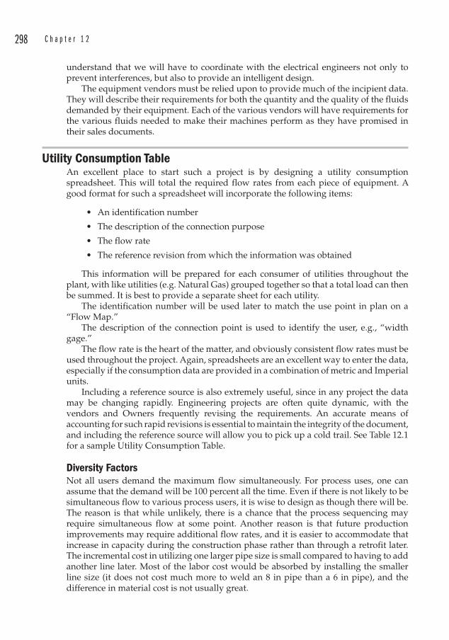
298 C h a p t e r 1 2
understand that we will have to coordinate with the electrical engineers not only to prevent interferences, but also to provide an intelligent design.
The equipment vendors must be relied upon to provide much of the incipient data. They will describe their requirements for both the quantity and the quality of the fluids demanded by their equipment. Each of the various vendors will have requirements for the various fluids needed to make their machines perform as they have promised in their sales documents.
Utility Consumption TableAn excellent place to start such a project is by designing a utility consumption spreadsheet. This will total the required flow rates from each piece of equipment. A good format for such a spreadsheet will incorporate the following items:
• An identification number
• The description of the connection purpose
• The flow rate
• The reference revision from which the information was obtained
This information will be prepared for each consumer of utilities throughout the plant, with like utilities (e.g. Natural Gas) grouped together so that a total load can then be summed. It is best to provide a separate sheet for each utility.
The identification number will be used later to match the use point in plan on a “Flow Map.”
The description of the connection point is used to identify the user, e.g., “width gage.”
The flow rate is the heart of the matter, and obviously consistent flow rates must be used throughout the project. Again, spreadsheets are an excellent way to enter the data, especially if the consumption data are provided in a combination of metric and Imperial units.
Including a reference source is also extremely useful, since in any project the data may be changing rapidly. Engineering projects are often quite dynamic, with the vendors and Owners frequently revising the requirements. An accurate means of accounting for such rapid revisions is essential to maintain the integrity of the document, and including the reference source will allow you to pick up a cold trail. See Table 12.1 for a sample Utility Consumption Table.
Diversity Factors Not all users demand the maximum flow simultaneously. For process uses, one can assume that the demand will be 100 percent all the time. Even if there is not likely to be simultaneous flow to various process users, it is wise to design as though there will be. The reason is that while unlikely, there is a chance that the process sequencing may require simultaneous flow at some point. Another reason is that future production improvements may require additional flow rates, and it is easier to accommodate that increase in capacity during the construction phase rather than through a retrofit later. The incremental cost in utilizing one larger pipe size is small compared to having to add another line later. Most of the labor cost would be absorbed by installing the smaller line size (it does not cost much more to weld an 8 in pipe than a 6 in pipe), and the difference in material cost is not usually great.
P i p i n g P r o j e c t A n a t o m y 299
DescriptionFlow (GPM)
Press(psig)
ReferenceAvg. Max. Min. Max.CGL entry hyd cooler 50 70 60 85 Utility Quality & Consumption
Data Rev D 4/15/97pay-off reel 5 5 60 85 Utility Quality & Consumption
Data Rev D 4/15/97cleaning section 0 0cleaning dryer 0 0cleaning fume exhaust
0 0
pot pre-heater 0 0pot 72 72 60 85 Utility Quality & Consumption
Data Rev D 4/15/97wiper 150 150 60 85 Utility Quality & Consumption
Data Rev D 4/15/97edge heater 0 0GA furnace 950 950 60 85 Utility Quality & Consumption
Data Rev D 4/15/97quench tank 1260 1800 60 85 Utility Quality & Consumption
Data Rev D 4/15/97skinpass mill 0 0tension leveler 150 150 60 85 Utility Quality & Consumption
Data Rev D 4/15/97roll force hyd cooler
45 55 60 85 Utility Quality & Consumption Data Rev D 4/15/97
chromatingsection
0 0
chromating fume exhaust
0 0
chromate dryer 0 0phosphatingsection
20 20 60 85 Utility Quality & Consumption Data Rev D 4/15/97
phosphate dryer 0 0width gauge 1 1 60 85 Utility Quality & Consumption
Data Rev D 4/15/97tension reel EPC 5 5 60 85 Utility Quality & Consumption
Data Rev D 4/15/97exit hyd cooler 50 70 60 85 Utility Quality & Consumption
Data Rev D 4/15/97annealing furnace 3150 3400 60 85 Utility Quality & Consumption
Data Rev D 4/15/97APC 0 0 Letter to MIC dated 6/10/97
DC-L-MHIA-186inductionequipment
800 800 60 85 Utility Quality & Consumption Data Rev D 4/15/97
CGL SUBTOTAL 6708 7548
TABLE 12.1 Galvanizing line cooling water requirements.
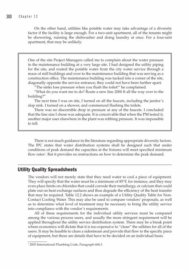
300 C h a p t e r 1 2
On the other hand, utilities like potable water may take advantage of a diversity factor if the facility is large enough. For a two-unit apartment, all of the tenants might be showering, running the dishwasher and doing laundry at once. For a four-unit apartment, that may be unlikely.
One of the site Project Managers called me to complain about the water pressure in the maintenance building at a very large site. I had designed the utility piping for the site, and routed the potable water from the city water service through a maze of mill buildings and over to the maintenance building that was serving as a construction office. The maintenance building was tucked into a corner of the site, diagonally opposite the service entrance; they could not have been further apart.
“The sinks lose pressure when you flush the toilet!” he complained. “What do you want me to do? Route a new line 2000 ft all the way over to the
building?”The next time I was on site, I turned on all the faucets, including the janitor’s
slop sink. I turned on a shower, and commenced flushing the toilets.There was no discernible drop in pressure at any of the faucets. I concluded
that the line size I chose was adequate. It is conceivable that when the PM tested it, another major user elsewhere in the plant was robbing pressure. It was impossible to tell.
There is not much guidance in the literature regarding appropriate diversity factors. The IPC states that water distribution systems shall be designed such that under conditions of peak demand the capacities at the fixtures will meet specified minimum flow rates1. But it provides no instructions on how to determine the peak demand.
Utility Quality SpreadsheetsThe vendors will not merely state that they need water to cool a piece of equipment. They will specify that the water must be a minimum of 85°F, for instance, and they may even place limits on chlorides that could corrode their metallurgy, or calcium that could plate out on heat exchange surfaces and thus degrade the efficiency of the heat transfer that may be required. Table 12.2 shows an example of a Utility Quality Table for Non-Contact Cooling Water. This may also be used to compare vendors’ proposals, as well as to determine what level of treatment may be necessary to bring the utility service into compliance with the vendor’s requirements.
All of these requirements for the individual utility services must be compared among the various process users, and usually the more stringent requirement will be applied throughout the utility service distribution system. There may be a break point where economics will dictate that it is too expensive to “clean” the utilities for all of the users. It may be feasible to clean a sidestream and provide that flow to the specific piece of equipment, but these are details that have to be decided on an individual basis.
1 2003 International Plumbing Code, Paragraph 604.3.
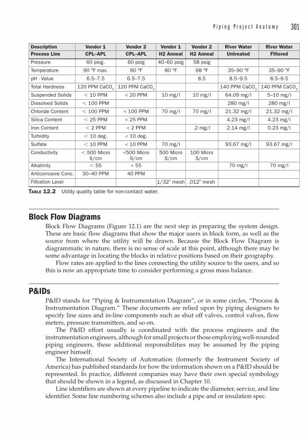
P i p i n g P r o j e c t A n a t o m y 301
Block Flow Diagrams Block Flow Diagrams (Figure 12.1) are the next step in preparing the system design. These are basic flow diagrams that show the major users in block form, as well as the source from where the utility will be drawn. Because the Block Flow Diagram is diagrammatic in nature, there is no sense of scale at this point, although there may be some advantage in locating the blocks in relative positions based on their geography.
Flow rates are applied to the lines connecting the utility source to the users, and so this is now an appropriate time to consider performing a gross mass balance.
P&IDsP&ID stands for “Piping & Instrumentation Diagram”, or in some circles, “Process & Instrumentation Diagram.” These documents are relied upon by piping designers to specify line sizes and in-line components such as shut off valves, control valves, flow meters, pressure transmitters, and so on.
The P&ID effort usually is coordinated with the process engineers and the instrumentation engineers, although for small projects or those employing well-rounded piping engineers, these additional responsibilities may be assumed by the piping engineer himself.
The International Society of Automation (formerly the Instrument Society of America) has published standards for how the information shown on a P&ID should be represented. In practice, different companies may have their own special symbology that should be shown in a legend, as discussed in Chapter 10.
Line identifiers are shown at every pipeline to indicate the diameter, service, and line identifier. Some line numbering schemes also include a pipe and or insulation spec.
Description Vendor 1 Vendor 2 Vendor 1 Vendor 2 River Water River WaterProcess Line CPL–APL CPL–APL H2 Anneal H2 Anneal Untreated Filtered
Pressure 60 psig. 60 psig 40–60 psig 58 psig
Temperature 90 °F max. 90 °F 80 °F 68 °F 35–90 °F 35–90 °F
pH - Value 6.5–7.5 6.5–7.5 8.5 8.5–9.5 8.5–9.5
Total Hardness 120 PPM CaCO3 120 PPM CaCO3 140 PPM CaCO3 140 PPM CaCO3
Suspended Solids � 10 PPM < 20 PPM 10 mg/l 10 mg/l 64.09 mg/l 5–10 mg/l
Dissolved Solids � 100 PPM 280 mg/l 280 mg/l
Chloride Content � 100 PPM < 100 PPM 70 mg/l 70 mg/l 21.32 mg/l 21.32 mg/l
Silica Content � 25 PPM < 25 PPM 4.23 mg/l 4.23 mg/l
Iron Content � 2 PPM < 2 PPM .2 mg/l 2.14 mg/l 0.23 mg/l
Turbidity � 10 deg. < 10 deg.
Sulfate � 10 PPM < 10 PPM 70 mg/l 93.67 mg/l 93.67 mg/l
Conductivity � 500 Micro S/cm
<500 Micro S/cm
500 Micro S/cm
100 Micro S/cm
Alkalinity � 55 < 55 70 mg/l 70 mg/l
Anticorrosive Conc. 30–40 PPM 40 PPM
Filtration Level 1/32� mesh .012� mesh
TABLE 12.2 Utility quality table for non-contact water.
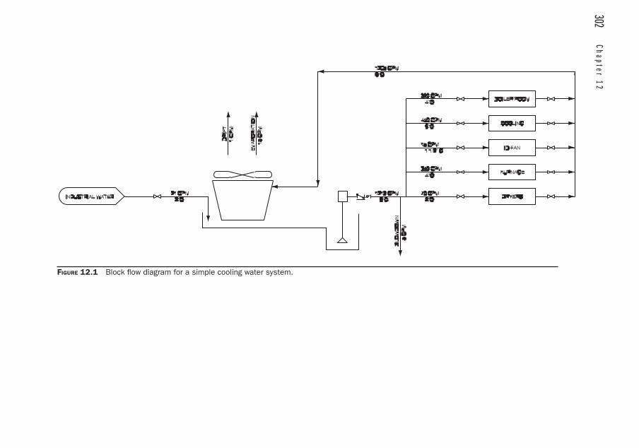
302 Chapter 12
FIGURE 12.1 Block fl ow diagram for a simple cooling water system.
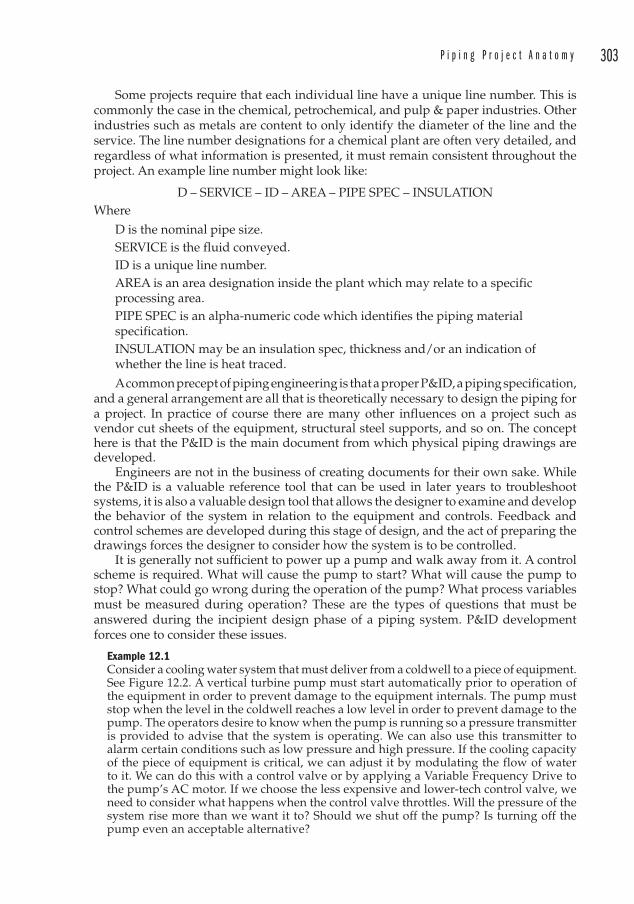
P i p i n g P r o j e c t A n a t o m y 303
Some projects require that each individual line have a unique line number . This is commonly the case in the chemical, petrochemical, and pulp & paper industries. Other industries such as metals are content to only identify the diameter of the line and the service. The line number designations for a chemical plant are often very detailed, and regardless of what information is presented, it must remain consistent throughout the project. An example line number might look like:
D – SERVICE – ID – AREA – PIPE SPEC – INSULATION Where
D is the nominal pipe size.SERVICE is the fluid conveyed.ID is a unique line number .AREA is an area designation inside the plant which may relate to a specific processing area.PIPE SPEC is an alpha-numeric code which identifies the piping material specification.INSULATION may be an insulation spec, thickness and/or an indication of whether the line is heat traced.
A common precept of piping engineering is that a proper P&ID , a piping specification, and a general arrangement are all that is theoretically necessary to design the piping for a project. In practice of course there are many other influences on a project such as vendor cut sheets of the equipment, structural steel supports, and so on. The concept here is that the P&ID is the main document from which physical piping drawings are developed.
Engineers are not in the business of creating documents for their own sake. While the P&ID is a valuable reference tool that can be used in later years to troubleshoot systems, it is also a valuable design tool that allows the designer to examine and develop the behavior of the system in relation to the equipment and controls. Feedback and control schemes are developed during this stage of design, and the act of preparing the drawings forces the designer to consider how the system is to be controlled.
It is generally not sufficient to power up a pump and walk away from it. A control scheme is required. What will cause the pump to start? What will cause the pump to stop? What could go wrong during the operation of the pump? What process variables must be measured during operation? These are the types of questions that must be answered during the incipient design phase of a piping system. P&ID development forces one to consider these issues.
Example 12.1Consider a cooling water system that must deliver from a coldwell to a piece of equipment. See Figure 12.2. A vertical turbine pump must start automatically prior to operation of the equipment in order to prevent damage to the equipment internals. The pump must stop when the level in the coldwell reaches a low level in order to prevent damage to the pump. The operators desire to know when the pump is running so a pressure transmitter is provided to advise that the system is operating. We can also use this transmitter to alarm certain conditions such as low pressure and high pressure. If the cooling capacity of the piece of equipment is critical, we can adjust it by modulating the flow of water to it. We can do this with a control valve or by applying a Variable Frequency Drive to the pump’s AC motor. If we choose the less expensive and lower-tech control valve, we need to consider what happens when the control valve throttles. Will the pressure of the system rise more than we want it to? Should we shut off the pump? Is turning off the pump even an acceptable alternative?
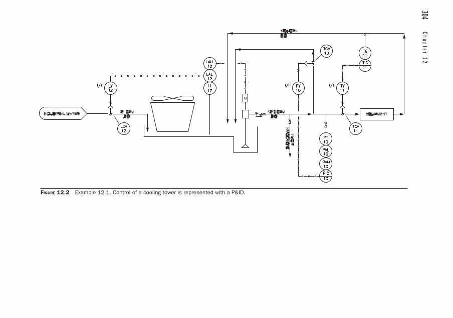
304 Chapter 12
FIGURE 12.2 Example 12.1. Control of a cooling tower is represented with a P&ID.
P i p i n g P r o j e c t A n a t o m y 305
Shutting the pump down completely is probably not the best option since:
• Frequent pump cycling is poor operating practice. The reason for this is due to wear on the motor starter, as well as energy surge in overcoming the inertia of a stagnant system (the rotational inertia of the pump impeller, as well as the inertia of the water in the system). This energy surge is expressed as an inrush current which may be 8 to 10 times higher than the motor’s rated current, and for large motors, there is often a penalty applied by the utility for frequent starting.
• There may be an advantage in keeping a small amount of cooling water flowing to prevent thermal cycles, or perhaps even boiling of the water if the item cooled is sufficiently hot.
While we could “turn down ” the pump speed with a VFD, we choose for this exampple to install a pressure bleed valve that will allow the pump to remain on at low flow to the equipment. Each of the different control loops is assigned a unique loop number . In this example, the pressure control loop is loop number 10, the temperature control loop is loop number 11, and a level control loop is loop number 12. The level control loop ensures that the water level is sufficiently high in the cooling tower basin to keep from starving the pump. The pump operation would become unstable if the water level became so low that vortices formed. Vortices at vertical pumps are always unwelcome since they can draw air into the pump suction.
General Notes On small projects there may not be a need to include a complete piping specification. A General Notes sheet will inform the contractor of the project’s general requirements. The General Notes provide an opportunity to instruct the contractor to:
• Verify dimensions. This is sometimes viewed as a shirking of the responsibilities of the engineer, but one must realize that there are good reasons for verifying dimensions. Consider first the case of new construction. The tolerance on setting structural steel columns has been observed in the field to be as much as 2 in. Since piping and equipment is often dimensioned from a column line, unless the contractor has verified the dimensions he cannot expect that a spool will fit. This is also a reason why it is important for the pipe fabricator to allow sufficient field trim on spools. Next consider a project in which piping must be designed into an existing installation. It would be the rare engineer who has the capacity to measure exactly the dimensions from tie point to tie point. Engineers simply are not as well equipped as contractors are for reaching high areas and drawing accurate dimensions in existing installations. This does not excuse bad dimensions on a drawing, but the engineer must recognize his limitations and make the contractor aware of them as well.
• Provide high point vents and low point drains. These are especially important during start-up and hydrotests, since it is impossible to secure a good hydro with air in the line. Also, it is good practice to provide vents and drains for normal maintenance.
• Provide sufficient field trim for spools and end connections at equipment.
306 C h a p t e r 1 2
• Provide adequate pipe supports. Engineered support details must still be provided by the engineer.
• Allow for gasket thickness between flanges, since it is never accounted for in normal piping layout drawings.
• Supply, install, and remove any start-up strainers required for flushing.
• Coordinate the work of other crafts prior to fabrication or erection.
Design Basis
A Design Basis should be included which states what codes are to be applied, as well as what assumptions had to be made in order to progress with the design. Some consulting firms provide a separate Design Basis, and these are often tomes that have evolved into lengthy design detail documents. These are almost always the product of an ambitious Project Manager who felt that “more is better.”
In the case of a Design Basis , less is more. The idea is to convey the general requirements of the project and permit the design professionals to exercise their engineering judgment in satisfying the project requirements, within the broad criteria established by the Design Basis.
A good Design Basis must address the concerns of the other disciplines, since engineering is a combined effort. Items to include in a Design Basis:
Recommended Data• Geographical data so that environmental loads may be determined from the
appropriate codes, and so that the proper Authority Having Jurisdiction (AHJ) may be identified.
• Applicable codes, that will certainly include the piping code, but may also include building codes . The building codes will provide information regarding the environmental loads , for example ASCE 7 “Minimum Design Loads for Buildings and Other Structures.”
• The source of piping and valve specifications. Will it be the Owner’s existing specification?
• The source of pipe support details, and the criteria used to determine whether a line should be stress analyzed.
• Environmental load data for seismic, wind, snow, and rain. Cite the source of such information.
• Temperature data, again citing the source and the criterion used, e.g., 2 percent dry-bulb temperature. Temperature data may not seem to have relevance to the piping engineer, but consider the task of specifying cooling towers. These data are available in the ASHRAE Fundamentals Handbook, Chapter 28, which now comes with a database on CD-ROM.
P i p i n g P r o j e c t A n a t o m y 307
Optional Data• Identity and contact information for the Authority Having Jurisdiction (AHJ) if
the project will require permitting, or if the AHJ’s opinion will be sought during the design phase.
• CAD standards may be included if the Owner has specific requirements for layer or level structures, or for the CAD platform to be used.
• Hazardous Area Classifications should be included if the project will include such areas. These will impact electrical equipment and cable and conduit installation.
Inappropriate DataThe following information should be represented elsewhere in the design or contract documents. They have no place in a thoughtful Design Basis :
• Schedules and milestones belong in a schedule. • Performance guarantees belong in a contract.• Utility consumption data, unless it is trivial. For a complex project, utility
consumption data should be in its own spreadsheet.• Safety and health requirements. While always integral to every project, mention
of safety and health in a design basis will force the document to become unnecessarily burdened with issues relating to liability.
General Arrangement The General Arrangement (GA) drawings show the equipment and structures. There may be more or less detail represented on such drawings, but generally all that is required of a GA is a dimensioned layout.
As with any plan drawing, the following elements must be represented:
• A north arrow for orientation. This is usually shown pointing to the top or left of the sheet. It is NEVER shown pointing to the bottom of the sheet. The actual north direction shown on all plans is “Plant North” which may deviate from “True North” by 45°. Sometimes both Plant North and True North are shown, but Plant North must always be shown.
• Column lines and identifying column bubbles should be shown. It is best to locate column bubbles along the top and right hand side of the drawings, and to remain consistent with the scheme. The reason for placing bubbles on the right hand side instead of the left is because they are easier to locate when bound in a stick file.
• On geographically large projects in which the design area of the project does not fit entirely on one sheet, it is useful to make a key plan to determine where the items represented on one sheet fit into the scheme of the plant grid. In that case, match lines are also required.
GAs traditionally mean plan views, but they are by no means restricted to plan views. It is often necessary to cut sections for GAs to show the relationships between equipment, to show lines-of-sight, to determine access to valves or equipment, or for any other reason.
308 C h a p t e r 1 2
Design and Construction Schedules
The best schedules will highlight the main milestones and project commitments, but will also clearly show what tasks are on the Critical Path . The Critical Path is the path through the schedule that determines how long the project will ultimately take to complete. It should show the earliest and the latest that each activity can start and finish without making the project any longer. “Slack Time” or “Float” is the amount of available time in a given activity that exceeds the time required to perform that activity.
A good Critical Path schedule can actually become a design tool for the engineer, since it forces one to consider constructability issues. Examples of this are:
• When must vendor certified data be available in order to complete piping tie-ins or equipment sizing?
• Will structural steel be available to hang piping?• When will concrete foundations be strong enough to set equipment?
Owners and Project Managers love aggressive schedules, but the clever PM will allow time for the unforeseen. This is more critical on small projects than on large projects, since anomalies may be absorbed without much notice on a very large project with many participants and lots of inertia. But on smaller projects, the absence of the IT specialist when the CAD system decides to crash may be significant. If everyone’s cars, families, and health were always reliable, there would be no need for insurance. Think of added slack time in a schedule as insurance.
A self-evident truth for design engineers is that on any project you can select any two of the following three:
• Schedule• Budget• Quality
One of these is going to suffer on a project, but Owners and Project Managers are always reluctant to acknowledge this. Quality better always be there. No one will be happy if the system does not work, and poor designs will lead to problems with budget or schedule. So a reasonable question at the beginning of a project is, “What matters more? Maintaining the schedule or meeting the budget?”
Flow Maps or Utility Distribution Diagrams In order to determine the sizes and general routings of headers, it is convenient to label the consumers of a single utility on a GA. The headers can be routed and the velocities, and hence the diameters, can be computed. This is a valuable tool during the incipient design phase. The consumption data is collected from the utility consumption charts.
Most schedules for large projects are prepared using canned software that is capable of producing reams of paper. These are most often printed on 8 1/2 in � 11 in paper, but even on 11 in � 17 in sheets they are incapable of showing the interrelationships of the various tasks at this scale. They are often prepared by Project Managers or Schedulers who delve too far into the minutia, leaving the project team with a bad case of data overload.
P i p i n g P r o j e c t A n a t o m y 309
Equipment Lists All but the smallest of owners keep track of their assets with equipment numbers. This facilitates maintenance, and ensures that the proper pump, for instance, is installed in the proper location. Equipment Lists are the tools used to keep track of the assets during the design phase. They will include data such as:
• Equipment number• Name (e.g., “Pump, CWS”)• Technical data (e.g., 450 GPM at 120 ft TDH)• Electrical data such as HP, Volts, Phase
Piping Plans, Sections, and DetailsThese drawings are really at the heart of piping projects. If the project is sufficiently large, the piping contractor will use these drawings to develop his spool drawings. Contractors (and hence Owners) can save money by having as much piping pre-fabricated in a pipe shop as possible, rather than out in the field. Shop-fabbed piping is less costly because:
• The piping is fabricated under more controlled conditions (more consistent temperature, out of the weather) and so quality issues may be mitigated.
• No work at height is required, so no manlifts or scaffolding are needed.• There is less time spent by crews having to reach the location where the pipe is
to be installed.• Field erectors make higher wages than shop fabricators, since the field work is
more demanding.
The fabricator will have likely seen these drawings at least once before, during the bidding phase. In order to develop his bid price, the contractor needs to perform a Material Take-Off , or MTO. The MTO is a list of all of the pipe, fittings, and specialties that he must purchase and install. A sample MTO is shown in Table 12.3. Quantities from the MTO are then entered into an estimating spreadsheet to develop the installed cost estimate.
Pipe Support Plans and Instrument Location PlansPast practice was to provide separate drawings to show the locations of supports or instrumentation. The piping plan was screened2 and the support of instrument was drawn darker so that it stood out on the drawing.
Because engineering has been forced into a competitive marketplace, these features are now most often shown on the regular piping plan, without the need for a separate drawing.
IsometricsPiping isometrics are most often used for conceptual layouts and stress analysis. The use of isometrics for routing small bore piping is very useful for the field engineer who must develop a bill of materials (a “take-off”) for procurement.
2 In the not-too-distant past, a darker-than-normal sepia could be made of the piping plan and the background erased to highlight the support or instrument.
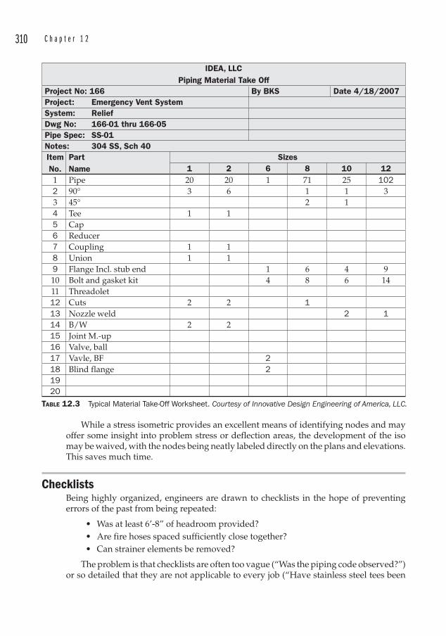
310 C h a p t e r 1 2
While a stress isometric provides an excellent means of identifying nodes and may offer some insight into problem stress or deflection areas, the development of the iso may be waived, with the nodes being neatly labeled directly on the plans and elevations. This saves much time.
ChecklistsBeing highly organized, engineers are drawn to checklists in the hope of preventing errors of the past from being repeated:
• Was at least 6’-8” of headroom provided?• Are fire hoses spaced sufficiently close together?• Can strainer elements be removed?
The problem is that checklists are often too vague (“Was the piping code observed?”) or so detailed that they are not applicable to every job (“Have stainless steel tees been
IDEA, LLCPiping Material Take Off
Project No: 166 By BKS Date 4/18/2007Project: Emergency Vent System System: ReliefDwg No: 166-01 thru 166-05Pipe Spec: SS-01Notes: 304 SS, Sch 40ItemNo.
PartName
Sizes1 2 6 8 10 12
1 Pipe 20 20 1 71 25 1022 90° 3 6 1 1 33 45° 2 14 Tee 1 15 Cap6 Reducer7 Coupling 1 18 Union 1 19 Flange Incl. stub end 1 6 4 910 Bolt and gasket kit 4 8 6 1411 Threadolet12 Cuts 2 2 113 Nozzle weld 2 114 B/W 2 215 Joint M.-up16 Valve, ball17 Vavle, BF 218 Blind flange 21920
TABLE 12.3 Typical Material Take-Off Worksheet. Courtesy of Innovative Design Engineering of America, LLC.

P i p i n g P r o j e c t A n a t o m y 311
used for oxygen service?”). Adding to the difficulty is the fact that most of these checklists are rolled out during the checking phase when the overnight mail truck is idling outside the front door, waiting to whisk the drawings to the construction site.
Checklists are fine, especially if your designs often follow the same routine, job after job. That is not always the case though, and the tendency is to pay little attention to a lengthy list during checking. It may sometimes be better to rely on a solid base of experience and technical knowledge than to try to distill every detail down into a recipe.
Document Control Drawings and specifications are assigned a revision number whenever they are issued outside of the engineering organization. The common convention is to assign letters and numbers for the various issues:
• A – APPROVAL. This is issued to the Owner to ensure that the engineer is representing the Owner’s requirements for the project. Vendors also issue drawings to the owner or engineer for approval. These drawings are marked up as required, and sent back to the drawing originator for consideration.
• B – BID. Bid issues are contractually sensitive, since these drawings are what the contractor bases his price on. Changes made after the bid issue should be clouded so that the extent of the revision is clear to all parties. The contractor will likely adjust his price or the schedule to account for any changes that occur after the Bid Issue, and this often has significant commercial consequences.
• 0 – CONSTRUCTION. Drawings are Issued For Construction once the engineer is satisfied that the current scope of the work is shown correctly on the drawings. Some engineering houses have a policy of removing all clouds from IFC drawings. This may be to the contractor’s disadvantage if any item that could affect cost or schedule has changed between the Bid Issue and the Construction Issue.
• 1, 2, etc. Revisions are issued as necessary to correct any problems or changes that have occurred since the preceding issue. These changes are clouded and identified with a revision triangle. Previous clouds are removed so that the drawing does not become cluttered, and so the latest change is immediately apparent to the reader of the drawing. It is a good idea to provide as detailed an explanation of the revision as space will permit, since the revision history may be important if a dispute should arise.
• CERTIFIED. Engineers always seem to be working with preliminary information, and against schedules that demand final data in order to complete the design. In order to establish tie-ins, it is imperative that the engineer knows the exact location of a nozzle, the flange rating and size, and the dimensions of the piece of equipment. The vendor provides this final information as a “certified” drawing. This certifies that the equipment will arrive on site exactly as shown on the drawings.
The terms “Issued for…” and “Released for…” are synonymous.Holds are sometimes placed on drawings if certain information is missing. Rather
than delay the issue of an entire drawing, a cloud is placed around the missing information with the word “HOLD.” It is a good idea to describe why the hold is there, for example “HOLD FOR VENDOR DIMENSION.”
312 C h a p t e r 1 2
Document issues are often accompanied by a formal transmittal, which is a list that describes what was issued. These transmittals are tiresome to prepare, but often form the only basis for confirming whether or not a particular drawing was sent. The use of a transmittal is encouraged for every project.
The transmittal will list the drawing number, the title, the revision, and the date of the issue. Sophisticated databases are sometimes used to enhance this effort.
After IFCOnce the drawings are Issued For Construction, there are often still questions or revisions. Questions or clarifications may be formally requested by the contractor through a “Request For Information” format, which will list the particular drawing, the revision, the date of the request, and the question. Lists of these RFIs are maintained, with all of the accompanying correspondence, and these should be retained by the engineer at the end of the project for two reasons:
1. They may form the basis for a defense against claims relating to scope, cost, or schedule.
2. They are an excellent review of information that may be better described in the next project.
Field Engineering The benefits of placing qualified engineers in the field during the construction phase cannot be underestimated. Very often these are the very engineers that designed the project, and in that case, so much the better. Aside from providing the field with dedicated technical resources, field work also provides the engineer with the opportunity to improve future designs by observing construction techniques and materials. It also affords an opportunity to build rapport with the owner and contractor, as well as defend the design.
The need to have the engineering firm’s interests represented should be obvious. The qualities possessed by field engineers should include:
• Loyalty to the engineering firm
• Technical competence
• The ability to function effectively in a field environment
• The ability to deal calmly with antagonism
• The fortitude to stand up to conflicting opinions regarding the design, when the design can be defended
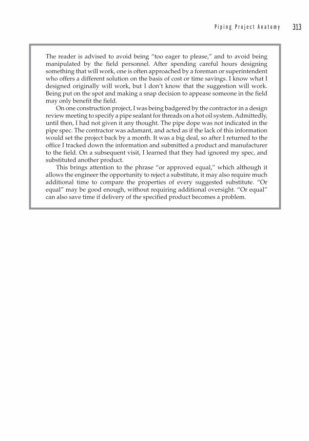
P i p i n g P r o j e c t A n a t o m y 313
The reader is advised to avoid being “too eager to please,” and to avoid being manipulated by the field personnel. After spending careful hours designing something that will work, one is often approached by a foreman or superintendent who offers a different solution on the basis of cost or time savings. I know what I designed originally will work, but I don’t know that the suggestion will work. Being put on the spot and making a snap decision to appease someone in the field may only benefit the field.
On one construction project, I was being badgered by the contractor in a design review meeting to specify a pipe sealant for threads on a hot oil system. Admittedly, until then, I had not given it any thought. The pipe dope was not indicated in the pipe spec. The contractor was adamant, and acted as if the lack of this information would set the project back by a month. It was a big deal, so after I returned to the office I tracked down the information and submitted a product and manufacturer to the field. On a subsequent visit, I learned that they had ignored my spec, and substituted another product.
This brings attention to the phrase “or approved equal,” which although it allows the engineer the opportunity to reject a substitute, it may also require much additional time to compare the properties of every suggested substitute. “Or equal” may be good enough, without requiring additional oversight. “Or equal” can also save time if delivery of the specified product becomes a problem.

This page intentionally left blank
315
CHAPTER 13Specifications
Engineers hate to write specifications. It is difficult and often dull work, with a lot of potential dire consequences if something is incorrect. The best specifications are well-organized, consistent, and easy to read.
A lot of trouble can be saved by requesting that the contractor review the specifications ahead of time, if possible. This is viewed by many engineers as opening the door to unwanted criticism, but having the contractor review the specs prior to issue is preferable to having them request substitutions during the construction phase. It also obviates the risk of having criticism leveled at the engineer. However, many times it is simply not possible to solicit input from the contractor.
Engineering is in many ways the science of finding shortcuts. We use CAD (and before CAD, sepias) to reproduce similar details and even entire layouts quickly, without having to start from a blank sheet of paper. Specs are no different. Old specs are recycled from one project to the next, with bits added or deleted as the engineer experiences new problems and remembers to file them for future reference for use in subsequent projects. The result is often a tangle of miscellaneous requirements listed in no particular order, and often in conflict within the same document. What is needed in such cases is a complete overhaul.
Types of SpecificationsWhen we think of specifications, the first that comes to mind is the piping spec. But we recognize that because of our unique position in projects, we may also be responsible for certain equipment specifications, as well as for construction specifications.
The requirements of the specifications are to define the expectations of the owner. The specifications will form part of the bid documents and will be relied upon to determine the cost of the project as well as the quality of the finished product.
Specification FormatsDepending on the particular specification, its format may be:
• An outlined narrative, which is more appropriate for equipment and construction specifications, but which has also been used for many years to prepare piping specifications.
316 C h a p t e r 1 3
• A table, which is more appropriate for some equipment and for most piping specifications. Tabulated datasheets for mechanical process equipment can be particularly useful since they condense the salient points in an easy to read format.
Equipment Specifications The piping engineer will often be required to prepare specifications for process equipment such as pumps, compressors, cooling towers, heat exchangers, and so on. One must recognize that the specifying engineer is not the equipment designer however, and the distinction between those roles should be respected in order to prevent the specification from being written in such a way that only one manufacturer meets the spec. Generally the whole idea behind writing specifications is to prepare a document from which competitive bids may be fairly solicited. Writing a pump spec that requires a proprietary feature stacks the deck in favor of the manufacturer who has the patent on that feature.
Performance based specifications are the best at arriving at competitive bids. Specific details should be limited to those absolutely necessary for the requirements of the application.
One capital project for a new steel-making process had an intensive equipment procurement component. The company I was working for had the Engineering and Procurement contract (E&P) and was writing many specifications for the ancillary equipment like conveyors, blowers, stoves, etc.
We needed a very large shell-and-tube heat exchanger. It turns out that there are not many suppliers of such equipment, but even so, a specification had to be written. I wrote the technical specification and the technical data sheet that described the performance required of the exchanger. Once the purchasing manager added the engineering company’s standard terms and conditions, various onerous appendices, and the owner’s addenda, the specification was approximately 3 in thick.
We waited for replies to our RFQ, and heard nothing. After a couple of weeks passed, I called one of the vendors (the one who I thought had the best chance of designing such an exchanger). He told me that they did not intend to bid on the project because they felt that the sheer size of the specification indicated that it was full of liability for them. We were back where we started.
Sample Outline 1. Definitions. This is an opportunity to identify terms to be used within the
specification. For instance, “Owner” may be synonymous with “Purchaser.” For an Engineering, Procurement, and Construction Management contract, the “Engineer” will be the same entity as the “Purchaser.”
2. Project location. It is important for bidders to understand where the equipment is to be delivered in order to account for freight costs, scheduling, and any environmental features that might need to be considered, such as freeze protection.
S p e c i f i c a t i o n s 317
3. Standards. A list of the applicable standards that are expected to be applied to the design and fabrication of the equipment should be included. But care should be taken, as this is the most abused portion of any equipment specification. A specification that lists “ASME, ANSI, UL, …” is meaningless. Does the specifier really intend that a manufacturer retains access to the hundreds of individual ASME codes? This shotgun approach is often viewed by the engineer as offering protection1 against the unknown. In reality, it is unenforceable, as it is too vague. On the other hand, if one indicates that flanges are to comply with ANSI B16.5, then that has meaning.A common statement that is appended to referenced standards is “latest edition,” indicating that the specifier expects the manufacturer to design to a different standard than the one the engineer used. Many standards change rarely, and are issued triennially as a matter of course (the B16.5 dimensions are probably going to be the same 10 years from now as they are now). But certain codes may change, and in order to avoid applying a double standard, consider indicating the revision date used for the design.Conflicts between specified standards may also arise. See the sidebar discussion in Chapter 7 regarding the API flanges on a basket strainer.Another pitfall is to specify an obsolete standard.
4. Scope of supply. This is likely to be the longest section of the spec, and may include references to drawings that clearly outline the scope of supply. On very large projects, the Owner may desire to purchase all of the motors in bulk from a motor manufacturer. This would be important to a pump bidder who is accustomed to providing drivers with the pumps.
A process engineer was managing an installation at a paper mill in Georgia. The project required a rectangular tank, a vessel supported within a structural steel framework, and lots of piping. Upon delivery of the tank, the process engineer discovered that a square manway cover was not provided by the vendor.
The cover plate was not called out on the tank drawing, nor in the scope of supply in the spec. The vendor had assumed that something else was going to bolt up to the square flange. The process engineer had assumed that the vendor would know to supply the cover. After all, what else would bolt up to a square manway?
5. Functional requirements. These should almost always be delineated in the form of a data sheet. This provides a convenient and organized means of assembling and reviewing the data. Figure 13.1 shows a sample data sheet for a centrifugal pump.
6. Schedule. As important as the date the equipment is needed on site for installation is the date that vendor data is required by the engineer to complete the design. Milestones for Approval Issues as well as Certified Drawings must be stated in the specification. Clever Purchasing Managers will tie the delivery of these milestones to the payment schedule.
1 The common term in engineering offices is “CYA,” enveloping a philosophy that is intended to protect the engineer from criticism. This philosophy never assisted a project in meeting a schedule or coming in under budget.
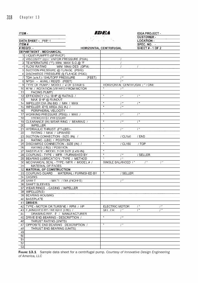
318 C h a p t e r 1 3
FIGURE 13.1 Sample data sheet for a centrifugal pump. Courtesy of Innovative Design Engineering of America, LLC
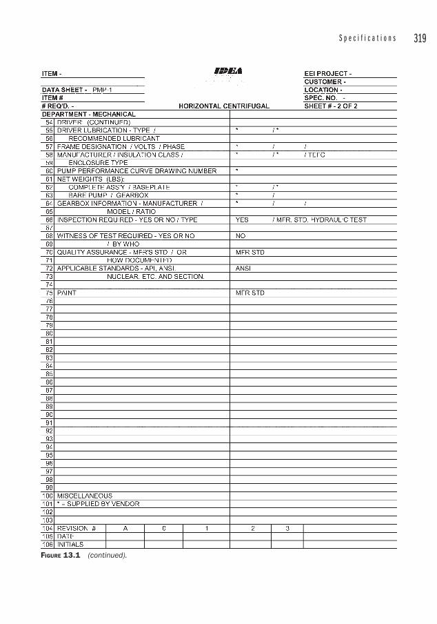
S p e c i f i c a t i o n s 319
FIGURE 13.1 (continued).

320 C h a p t e r 1 3
7. Details of supply. Suppose you are writing a specification for a large piece of equipment; one too large to be handled in a single shipment. Usually the individual components arrive at different times, and rarely are they installed immediately. So once it gets on site, it must be unloaded, stored, moved to the installation location, and assembled. A procedure must be in place to ensure that nothing gets misplaced, and that the assembly progresses smoothly. Some suggestions to facilitate this are:
A. Start-up troubles can be detected in the manufacturer’s shop if the equipment lends itself to a shop test there. The vendor has the added incentive of correcting the problem because the equipment is taking up space on the shop floor. (Not that a vendor would not give your equipment sitting in the field top priority.)
B. Match marking prior to knocking the equipment down for shipment is a simple procedure that can greatly reduce erection time.
C. Designing a system to be skid-mounted removes many of the variables that add to project duration and cost. Pre-piping and pre-wiring to terminal blocks should also be specified.
D. Insist that every crate, box, or component is labeled with the vendor’s name, vendor’s telephone number, purchase order number, and equipment number. This is useful to the field engineers in any case, but is imperative where a vendor is supplying multiple pieces of similar equipment. When something is missing or damaged in the field, there is nothing like immediate access to the vendor without having to track down the paperwork. The first thing the vendor asks is, “What is the PO number?” Having it labeled on the equipment is a definite advantage.
E. Every piece of equipment should be labeled indelibly with its equipment number. Nameplates must be legible and remain unpainted.
8. Delivery details. If the project has special requirements for unloading equipment at the site, they must be stated in the bid documents. This may be addressed in an appendix or in the body of the specification.
9. Technical data. It is easy to get carried away in requesting technical data, and one must take care to not request lubrication data for a heat exchanger. Some bureaucratic document control departments may not approve progress payments if they have not received all of the documentation they are supposed to have. (This is more likely if the receipt of technical data has been tied to the schedule of payments.)
A matrix of required data is a convenient way to display what data is required, and how many copies of each will be needed to distribute among the design engineers, erectors, and owner’s maintenance files.
10. Intent to bid . An intent to bid form should be included with instructions to the bidders to return a signed copy a short time after the bid packages have been issued. The bidders should indicate that they will or will not submit a bid. If competitive bids are required, this may give the engineer time to locate and solicit bids from alternate vendors.
Provisions should be made for questions from bidders to be answered. The fairest way to deal with questions is to list all of the questions and answers from all of the bidders, and to distribute the Q&A to all of the bidders. This ensures that everyone has access to the same information. Questions may be submitted in person or over the
S p e c i f i c a t i o n s 321
phone, at the engineer’s and purchasing agent’s discretion, but answers should be in writing to all interested parties.
Bid Tabulation
A clever way to prepare bid tabs is to provide the spreadsheet format to the vendors, and require them to complete the information electronically (price, terms, delivery, technical data). These completed columns may then be cut and pasted into the master bid tab to provide an accurate comparison of the important details that will be considered in the purchase decision.
In this way, the engineer does not have to sift through varied bid formats to extract the information requested. Nor does he have to re-enter information (risking an incorrect entry or typographical error). Make the vendor use your format.
Bid tabulations are required to determine which vendor will be awarded the purchase order. In tabulated form the bids are easily compared to each other, and gaps in the information are more easily identified.
Bid tabs should include all of the contact information as well as the technical and commercial details.
Pipe SpecificationsCSI Format Editable outlines are available from organizations such as the Construction Specifications Institute2 to provide engineers and architects with an organized format for the preparation of specifications. The advantages of using such a format are:
• It provides a standard format that contractors, owners, engineers and architects recognize.
• It permits every project spec to look like every other project spec.• It saves time in the preparation of the specs.
While these specifications excel in HVAC piping or plumbing projects (as well as the architectural projects for which they are tailored), they are poorly adapted to industrial projects, which may have dozens of piping services, many of which are not part of the pre-written specs.
Prior to 2004, the entire format consisted of 16 “Divisions,” with the Mechanical Specifications listed under Division 15. Each specification was assigned a five-digit number, with the first two digits indicating the division. The format was expanded in 2004 to 50 divisions, with each specification consisting of a six-digit number. The piping-related specifications were moved to Division 22. Again, the first two digits identify the division number.
Each specification contains three parts:
1. General. This part identifies related sections in the specification, reference standards, required submittals, quality assurance requirements, the need for pre-installation meetings, delivery and storage requirements, warranty information, and whether any spare materials may be required.
2 CSI, 99 Canal Center Plaza, Suite 300, Alexandria, VA 22314, http://www.csinet.org.
322 C h a p t e r 1 3
2. Products. This section details materials to be used.
3. Installation. This section describes installation requirements that may or may not be shown on the detail drawings.
That there may be discrepancies between the specifications and the drawings may be surprising, but it is common enough that the contract documents often contain language specifying the “Order of Precedence of Documents, ” which may look like:
• Contract • Special Provisions• General Provisions• Specifications• Details on Drawings• Plan Drawings
This indicates that the contract language reigns supreme and that specifications would take precedence over drawings.
Outlined NarrativeThis is the most common format of industrial piping specification. Each specification describes the requirements for each of the various piping services. Thus, there may be separate specifications for cooling water, natural gas, compressed air, etc.
The problem with writing specifications for each individual service is that it becomes difficult to compare multiple specifications. There may be only slight differences between two or more specifications, and these differences could go undetected, losing an opportunity to combine specs that are only slightly different.
There are advantages to combining similar specifications:
• The number of specifications are fewer and therefore are easier to manage.
• The specifications are simpler and there may be fewer different fittings or valves. From the contractor’s viewpoint, the fewer different fittings and valves, the better.
• The specs may be combined into one of several service classifications, like standard weight carbon steel with 150 lb flanges. A single service classification may be able to include a number of fluid services.
There will likely be a sub-specification for lines 2 in and smaller. The reason for this is twofold: for welded lines, it is far easier to use socket-weld fittings instead of butt-welds, and for other systems, it will be more economical to use threaded and coupled, or screwed connections. (Even on a system such as compressed air, in which threaded connections lead to excessive leakage, it may be easier to install T&C piping and seal weld the connections.) So there will usually be a break within the spec to describe the differences between the smaller bore piping and the larger bore piping. That break most often falls between 2 and 2 1/2 in.
There also may be entirely separate specifications for a single fluid service that runs both above and below ground. Flanges may not be permitted below ground, or the engineer may desire to use a material like HDPE below ground and steel above ground. The HDPE is a good choice below ground, but would be extremely difficult to support above ground.
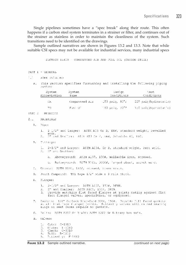
S p e c i f i c a t i o n s 323
Single pipelines sometimes have a “spec break ” along their route. This often happens if a carbon steel system terminates in a strainer or filter, and continues out of the strainer as stainless in order to maintain the cleanliness of the system. Such transitions need to be identified on the drawings.
Sample outlined narratives are shown in Figures 13.2 and 13.3. Note that while suitable CSI specs may not be available for industrial services, many industrial specs
FIGURE 13.2 Sample outlined narrative. (continued on next page)
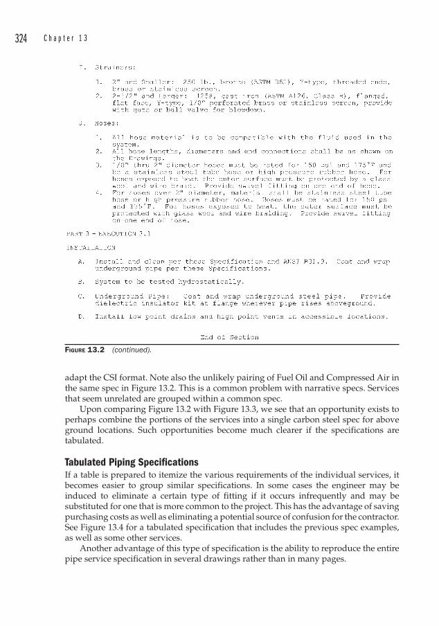
324 C h a p t e r 1 3
FIGURE 13.2 (continued).
adapt the CSI format. Note also the unlikely pairing of Fuel Oil and Compressed Air in the same spec in Figure 13.2. This is a common problem with narrative specs. Services that seem unrelated are grouped within a common spec.
Upon comparing Figure 13.2 with Figure 13.3, we see that an opportunity exists to perhaps combine the portions of the services into a single carbon steel spec for above ground locations. Such opportunities become much clearer if the specifications are tabulated.
Tabulated Piping SpecificationsIf a table is prepared to itemize the various requirements of the individual services, it becomes easier to group similar specifications. In some cases the engineer may be induced to eliminate a certain type of fitting if it occurs infrequently and may be substituted for one that is more common to the project. This has the advantage of saving purchasing costs as well as eliminating a potential source of confusion for the contractor. See Figure 13.4 for a tabulated specification that includes the previous spec examples, as well as some other services.
Another advantage of this type of specification is the ability to reproduce the entire pipe service specification in several drawings rather than in many pages.
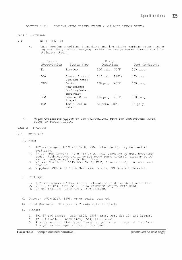
S p e c i f i c a t i o n s 325
FIGURE 13.3 Sample outlined narrative. (continued on next page)
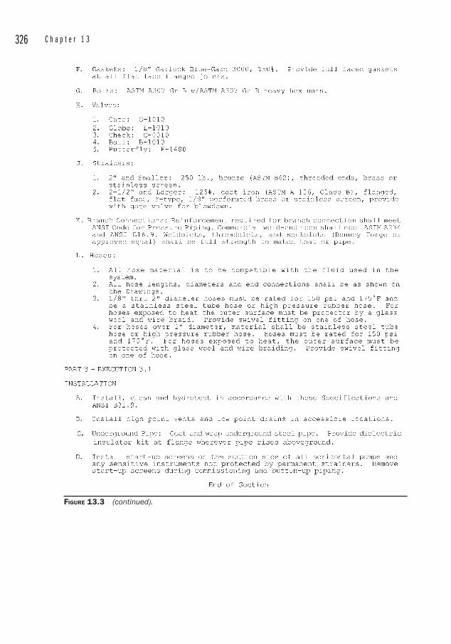
326 C h a p t e r 1 3
FIGURE 13.3 (continued).
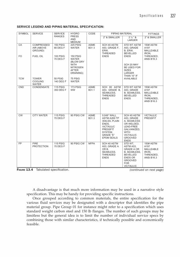
S p e c i f i c a t i o n s 327
A disadvantage is that much more information may be used in a narrative style specification. This may be handy for providing specific instructions.
Once grouped according to common materials, the entire specification for the various fluid services may be designated with a descriptor that identifies the pipe material group. Pipe Group 01 for instance might refer to a specification which uses standard weight carbon steel and 150 lb flanges. The number of such groups may be limitless but the general idea is to limit the number of individual service specs by combining those with similar characteristics, if technically possible and economically feasible.
FIGURE 13.4 Tabulated specifi cation. (continued on next page)
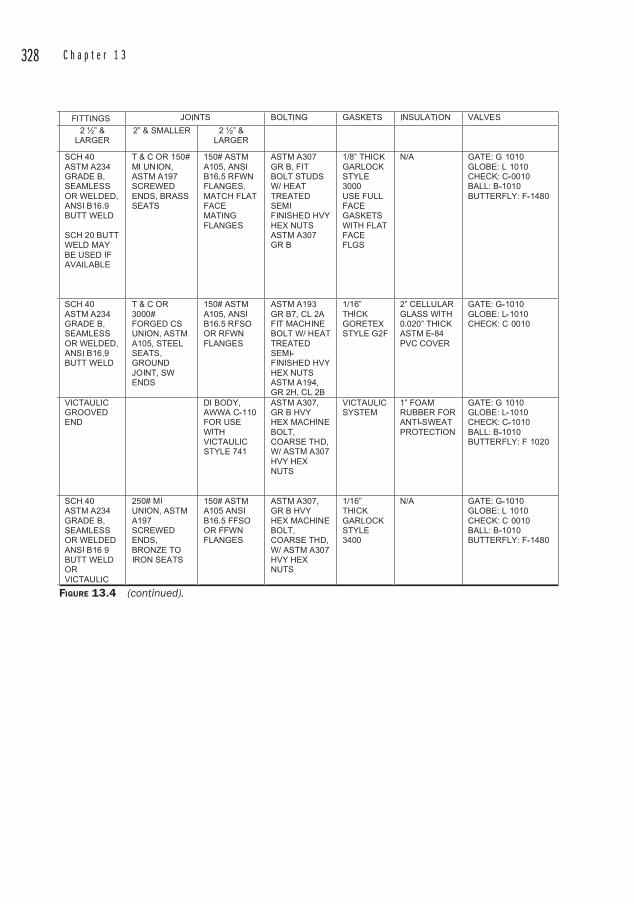
328 C h a p t e r 1 3
FIGURE 13.4 (continued).
329
CHAPTER 14Field Work and Start-up
An electrical engineer once told me that he can tell if someone doesn’t know what they are doing in an electrical room by watching how they act around the equipment. “If you see someone leaning against an MCC enclosure, right away you know he doesn’t know anything about electrical gear. ” He explained that some electricians in a paper mill he worked at exposed a bus bar to perform maintenance. They found that a mound of wood dust had accumulated on one of the buses, reaching almost to the top of the enclosure. Had the dust touched it, the entire enclosure could have been energized.
NEVER LEAN AGAINST ELECTRICAL GEAR.When opening or closing an MCC switch, stand to the side of the bucket (the
term for the switch compartment). Press the palm of your non-dominant hand against the switch handle (don’t grasp it), look away, and throw the switch. This procedure is recommended to minimize your exposure in the event of an arc-fault in the equipment. Better yet, get an electrician to energize the gear.
There are countless ways to get injured in an industrial environment. It is not sufficient to keep your wits about you; you must also be aware of what others are doing so that their careless actions do not injure you. An injury can be a life-changing event.
Many safety rules are common sense and some are just onerous. I worked in a steel mill where hard hats and safety glasses were mandatory even while driving a car through the site. At some point, common sense really does have to play a role.
SafetySafety should be the top priority always, but engineers who perform field work would be wise to take a moment to consider the particular hazards of their environment. This is particularly vital since the field may be a bit foreign after having been confined for awhile to the office.
Acute safety hazards may be obvious, but some of the latent hazards are particularly insidious. These generally relate to environmental conditions such as what is present in air (asbestos, lead fumes, mold, chemicals, and so on).
Another consideration is that start-ups are essentially “boundary conditions” in the parlance of differential equations, and all of the interesting things seem to happen
330 C h a p t e r 1 4
during those times. Certainly there may be equipment or instrumentation failures during steady-state operations, but start-ups are notorious for damage to equipment, property, and even personnel. The reasons may include:
• Lack of familiarity with operation of the system
• Dynamic instability of the system
• Poor housekeeping as a result of construction activities
• Equipment or instrumentation malfunction
• A perceived sense of urgency
A start-up plan should also contain a safety plan , but as a minimum the following rules should apply any time you are in a field environment:
1. Never walk under a load. Loads shift, hoists fail, and crane operators have enough to worry about without being distracted by someone wandering under a load.
2. Never lean against electrical equipment.
3. Never look at a welding arc. This leads to a “flash” which is a painful eye condition. It can also seriously damage your eyesight.
4. Do not stand in front of the heads of reciprocating pumps or compressors. The heads do not often blow, but why take the chance?
5. If using a ladder behind another person, wait until the other person clears it before ascending or descending, in case of slipping, falling, or dirt falling off of shoes from above.
6. Make sure pressurized systems are safely vented before attempting repairs or opening flanges.
7. Be always mindful of where a tape measure could fall if it buckles when extended. Beware of open buses, as at crane hot rails.
8. Be aware that many aging installations still contain asbestos pipe insulation, and many of these installations are in poor condition.
9. Check with the site manager to determine risks of exposure to hazards like asbestos, ionizing radiation, lead fumes from abatement programs, etc.
10. Cultivate the habit of never taking a step backward without first looking behind you.
11. Pass through personnel doors instead of overhead doors.
12. Always let the operators know you are in the area. It’s both a courtesy and an opportunity for them to alert you to any potential hazards.
13. Establish eye contact with forklift operators or other equipment operators when sharing the same work area.
F i e l d W o r k a n d S t a r t - u p 331
I was taking photos to document the progress on a black liquor recovery boiler rebuild. The boiler had suffered a steam explosion inside the firebox and I was assigned to follow progress for a client. The boilermakers and welders were taking their morning break, and I crawled inside a polyethylene enclosure that had been erected to minimize drafts that could interfere with the critical weld puddles at the boiler tubes. I noticed a strong garlic odor and wondered what the boilermakers were having for breakfast. After I snapped a few flash photos of the tube membranes, I heard a hissing. I traced the hissing to a cutting torch lying on the scaffold planking. As I turned the torch in my hand, a blast of acetylene gas streamed into my face, and I understood where the garlic odor originated. I also realized that the poly tent was rapidly filling with highly combustible gas, and I quickly exited, notified the foreman, and realized how lucky I was that my flash had not ignited the gas.
WalkdownsIn an operating plant, or on a start-up, you often need to operate valves and energize equipment. A walkdown of the system is required to verify that the line is ready to be pressurized. This will include checking that all of the valving is in the correct position, that equipment is connected (or not connected), that blinds are in the correct orientation, and finally, that the system is actually complete. Many construction projects have fairly elaborate schemes for alerting personnel to the readiness for operation. These often take the form of color coded tags to indicate that the fitters have signed off on the system, that the line has been pressure tested, and that pumps have been lubricated and aligned. Another walkdown can’t hurt.
Check that test gags have been removed from Pressure Safety Valves. Check that limit stops have been removed from spring hangers, and that the hangers have been adjusted for the cold (or once heated, the hot) position.
Pumping systems need to be checked for the ability of the pump to maintain a prime. But prior to filling a well or vessel with liquid, it is imperative to examine the vessel for cleanliness. A QA program during construction should also minimize the amount of debris left inside piping, which can be considerable. The lines should be inspected wherever possible, and during construction of potable water lines this is especially important. Water mains under construction must be sealed at the end of the workday to prevent wildlife from entering.
A cooling water system was being started up at a steel mill. The fitters had been spitting sunflower shells into the coldwell throughout construction, and no one thought it was important to sweep them out before water was added. Unfortunately, the strainers had been purchased without automatic blowdowns in an effort to save money. These were large basket strainers, and when the vertical turbine pumps were started, the bottoms of the baskets were blown out of the strainers since the sunflower shells blinded the screens.
332 C h a p t e r 1 4
The tendency to develop an all-encompassing list of things to check has limited value. The reason is that certainly something important will be omitted from the list, and a too-cumbersome list will quickly lose the interest of the individual doing the checking. A better strategy is to develop an ongoing, project-specific checklist as the design progresses.
Pipe Cleanliness Pipe cleanliness is an issue that is often ignored. Cleanliness may not be crucial to many systems, but it is often a problem due to sanitary reasons, abrasion of delicate components such as instrumentation or rotary joints, or contamination of the fluid transported.
Some of the problems associated with pipe cleanliness may be obviated during the design phase by specifying materials that are easier to clean, or even less likely to get dirty to begin with. One example is the use of stainless steel piping, which does not contain mill scale or introduce slag during welding the joints. Another example is the use of pre-cleaned hydraulic piping. Some proprietary hydraulic piping uses mechanical joints to eliminate welding, and the number of fittings is further reduced through bending the pipe rather than having to include elbows. The pipes arrived at the site pre-cleaned for hydraulic service. Hydraulic service is one of the most demanding for cleanliness due to tight clearances in control valves.
In many cases, the MOC will be carbon steel, and it will need to be cleaned. Some procedures such as banging on the pipes with hammers to knock off loose scale have dubious merit. Other procedures suggest that hot fluids be circulated in the system, the theory being that the expansion and contraction of the metal pipe will loosen mill scale and dirt. Flushing the lines relies on rather high velocities, on the order of 12 to 15 ft per second in order to entrain particulates and carry them to a collection point. The flushing fluid is selected in most cases to be compatible with the operating fluid.
Specifying a TIG weld for the root weld can help minimize the introduction of welding slag inside the pipe. The welds can then be completed with the more common stick welding.
Good practice requires that fabricated reservoirs are cleaned in the fab shop and sealed against the entry of contaminants (which may include humidity) prior to shipping to the site. Other precautions for critical systems will include magnets to trap ferrous particles in reservoirs, non-bypass filters, baffles to drop out particulates, and low-point drains.
Some very elaborate flushing procedures have been developed by contractors who specialize in cleaning pipes. These can include acid cleaning at high temperatures, filtration, draining, and passivation of the internal surfaces. One should be alert to the limitations of even elaborate procedures however.
During the start-up of a hot oil calender system, the cleaning solution was circulated for several hours at a temperature of approximately 140°F. After passivation , the system was blown out with dry air, but a small amount of water from the passivation solution remained. As the system was started up with hot oil, the water flashed to steam resulting in tremendous water hammer. Worse, the operating temperature of 400°F was sufficient to melt the varnish-like coating inside the pipes. The acid etch at 140°F was not sufficient to remove this coating, and it peeled off in sheets, collecting in the strainers and quickly blinding them.
F i e l d W o r k a n d S t a r t - u p 333
Start-up strainers are often used to catch miscellaneous debris that collects in lines during start-up. These so-called “witches’ hats ” are installed in spool pieces just before the pump suction to protect the pump internals. After the fluid has been circulated for several hours the system is drained and the strainers are removed. The orientation of the strainers is always with the point of the hat upstream. This reduces the chance of damage to the strainer due to collection of debris at the center.
Vigorous construction management should enforce pipe cleanliness. Frequent inspections should ensure that fitters are not using pipes as garbage containers. Hard hats, cigarette butts, soda cans, wooden blocking, and plastic bags must never enter a pipe.
Sample Bearing Lube Oil System Cleaning Procedure 1. Clean the inside of the reservoir with clean rags.
2. Bypass the bearings with tubing.
3. Secure a filter bag (or nylon stocking) on the return line.
4. Add 55 gallons of low quality straight mineral oil (no additives) of 100 SUS at 100°F to the reservoir.
5. Circulate the oil for 1/2 hour, change filter bag, and repeat.
6. Drain flushing oil and fill with working fluid.
7. Circulate lube oil.
Sample Hydraulic Oil System Cleaning Procedure 1. Clean the inside of the reservoir with clean lint-free rags.
2. Bypass restricting valves, pumps, cylinders, and equipment.
3. For older systems that have been in use, flush with a solvent that can attain 100 SUS at the circulating temperature. For new systems, fill and flush with the working fluid.
4. Secure a filter bag (or nylon stocking) inside the return line to prevent contaminants from entering the reservoir.
5. Flush for four hours.
Additional information on pipe cleanliness may be found within PFI-ES5 “Cleaning of Fabricated Piping.”
PumpsPumps can be damaged in a number of ways during start-ups. Inadequate lubrication, improper coupling alignment, poor suction conditions, debris entering the pump, and incorrect direction of rotation are all hazards that await the start-up engineer. The direction of pump rotation should always be checked prior to installing the coupling1. This is generally done by “bumping ” the motor. This involves turning the motor on and off very quickly. Once rotation is verified, the coupling may be aligned. Incorrect rotation on a centrifugal pump can loosen the impeller in some pump designs, so the best method is to bump the motor BEFORE connecting it to the pump shaft. Even in this
1 This coupling connects the driver shaft to the pump shaft.
334 C h a p t e r 1 4
case, the motor should only be energized for a short time since the mounting bolts are not always properly torqued.
Extreme care and caution must be exercised when energizing a motor. The area should be cleared of unnecessary personnel and good housekeeping practices should be enforced prior to start-up. In some cases, the pump may already be connected to the motor, and it may be impractical to have them uncoupled. In this case, ensure that someone has signed off on the correct rotation prior to energizing the motor. And then only bump it to verify the rotation.
Most of the poor suction conditions that may occur should have been eliminated through the application of proper design. Some, however, cannot be designed out of the system. Consider a plastic bag that has been drawn against the suction strainer of a foot valve. Short of emptying the reservoir or entering it, probably the best technique is to start and stop the pump in the hope of allowing the falling column of water to push the bag far enough away from the foot valve that it can be snagged with a hook.
Where large horsepower pumps are concerned, it is worthwhile to purchase the assistance of the manufacturer’s field service technician. They will examine the pump for proper installation, in some cases even verifying impeller clearances. The ability to have access to an equipment expert on-site is not to be underestimated during start-up.
VentingHigh point vents should be used to rid air from liquid systems. This is imperative in hydraulics systems.
The operation of vents must always be checked prior to filling or draining tankage. This is particularly important after construction turnover or after maintenance has occurred on the tank.
If a vent is blocked, even by a thin sheet of polyethylene, and air is not admitted through the breather vent when the tank is pumped out, the tank wall can collapse with spectacular results due to the negative pressure resulting from the liquid leaving the tank. Pressure equalization during pump-out is paramount to tank operation.
Steam Systems Travel stops on spring hangers must be removed prior to placing the steam system in service. Spring hanger manufacturers generally paint these red for visibility and band them into place for shipping. They also take the additional precaution of tagging them
It is worth mentioning that the contractor should be made aware of the necessity of assigning qualified personnel to the task of installing pumps. Some union-staffed projects will make arguments that the job of installing the pumps ought to belong to the pipefitters since the pumps are connected to piping. Some will insist that because the pumps have motors the setting of pumps ought to belong to the electricians. Probably the best choice is to have the pumps set by millwrights, but anyone qualified can set a pump. The danger in having unqualified crafts set pumps is the risk of damage to the shafts and keyways, the lack of a proper coupling alignment, or improper shimming.

F i e l d W o r k a n d S t a r t - u p 335
with a caution to remove them prior to placing the steam system into service. But the start-up engineer will want to verify that they have indeed been removed. Prior to start-up, spring hangers need to be checked that they are set at the cold position.
Steam systems produce a considerable amount of condensate on start-up due to the cool mass of the piping. Large systems should be designed with supervised start-up, bypassing the steam traps and wasting the condensate. Smaller systems may be designed with an unsupervised start-up. Supervised start-up means that the steam traps are manually bypassed until the piping has heated up sufficiently to produce a normal amount of condensate that can be handled efficiently by the steam traps. Such large systems are usually not cycled on and off frequently, so the manual or supervised start-up is not onerous. Smaller systems may be shut down more frequently and so the unsupervised start-up is more convenient.
On large steam systems, warm-up jumpers across large valves are used to prevent large temperature swings which could shock equipment like turbine blades or create large quantities of condensate which may lead to water hammer. Small diameter globe valves are used to bypass the header gate valves, and some large gate valves are supplied with bosses cast into the bodies to accommodate the taps for warm-up bypass valves.
Steam lines should not be started up unless the insulation has been installed. Aside from the obvious safety hazard, the loss of heat leads to poor economy and excessive condensate.
Once cleared for start-up, the steam system should be blown down to a safe location outside the building. The steam system needs to be brought to saturation temperature to loosen mill scale and dirt, and to melt or soften any lacquer or oils that may be present inside the piping. The steam traps and heat transfer equipment must be valved off at this time, entirely bypassing the condensate return system so that the traps are not damaged by the sludge inside the steam lines. Once the steam system is clean enough to place in service, the traps and condensate return system can be placed in service, but the condensate should be sewered until it is clean enough for re-use.
Once the steam system is up to temperature, any variable spring hangers should be checked to ensure that the indicators are pointing to the “hot” position. If they are not, the hanger should be adjusted until the spring is loaded to the hot position. Once this adjustment is made, no further adjustment to the hanger is required.
Steam systems should be blown down to eliminate air (noncondensibles) from the system. Be aware that blowing down a steam line creates a considerable amount of noise. The design should include provisions to blow down the steam line to a safe location outside, preferably terminating in a silencer.
Compressed Air As mentioned elsewhere, rental compressed air is often required during start-up. This will often be on the critical path for starting up the other piping systems. Once a source of air is ready and the system is ready for pressure testing, the lines are blown down to remove as much particulate matter and oil and water as feasible. Because this will create an intense amount of noise, hearing protection is required of all personnel in the area.

This page intentionally left blank
337
CHAPTER 15What Goes Wrong
Fires Fires would not normally have much effect on a carbon or stainless steel water piping system. Consider the metallurgy. Steel pipe is formed at extremely high temperatures, so a pipe subject to a structural fire would not necessarily be exposed to a temperature higher than that at which it was manufactured. A visual examination of the piping (absent structural damage to the supporting system or physical damage due to falling debris) may be enough to merit performing a hydrotest to determine fitness for service. Materials used for valve seats and packings, and gaskets need to be investigated to determine whether these need to be replaced prior to the pressure test, since many of these materials will have melted or distorted in a fire.
For critical piping systems handling steam, compressed gases, or dangerous chemicals, it is advisable to remove sample coupons for metallurgical testing.
FloodsPiping is required to be pressure-tight, so the chances of flood waters entering a closed system are minimal, especially when one considers that the external pressure induced by a flood is perhaps a few feet of water. An external pressure of 5 psi would be quite a flood, and the floodwaters would be unable to penetrate a system rated at 150 psi.
Damage to piping systems by flooding is usually confined to:
• Physical damage due to shifting debris
• Wetting of insulation
• Salt water contamination of the exterior of pipes, leading to higher-than-normal corrosion rates
• Empty pipes having floated off of supports. Empty plastic underground piping can lift out of soil in non-flood conditions if it was installed without anchors and the water table rises.
Wet insulation has lost its insulating properties and must be replaced. This can be a significant project, and one that could have been avoided through the use of closed-cell insulation, which will not become wet. Cellular glass insulation is an example of this.
Saltwater contamination may simply be washed off of uninsulated piping and equipment. Very often after a flood , mud and silt accumulate around equipment and low piping. The sooner this is removed the better, as it will continue to hold the moisture
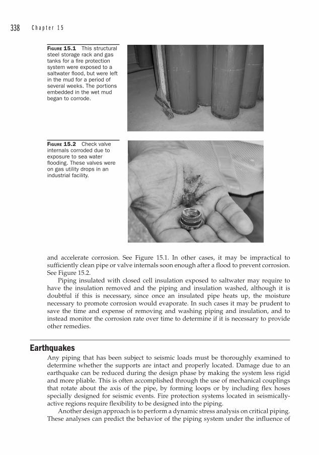
338 C h a p t e r 1 5
and accelerate corrosion. See Figure 15.1. In other cases, it may be impractical to sufficiently clean pipe or valve internals soon enough after a flood to prevent corrosion. See Figure 15.2.
Piping insulated with closed cell insulation exposed to saltwater may require to have the insulation removed and the piping and insulation washed, although it is doubtful if this is necessary, since once an insulated pipe heats up, the moisture necessary to promote corrosion would evaporate. In such cases it may be prudent to save the time and expense of removing and washing piping and insulation, and to instead monitor the corrosion rate over time to determine if it is necessary to provide other remedies.
Earthquakes Any piping that has been subject to seismic loads must be thoroughly examined to determine whether the supports are intact and properly located. Damage due to an earthquake can be reduced during the design phase by making the system less rigid and more pliable. This is often accomplished through the use of mechanical couplings that rotate about the axis of the pipe, by forming loops or by including flex hoses specially designed for seismic events. Fire protection systems located in seismically-active regions require flexibility to be designed into the piping.
Another design approach is to perform a dynamic stress analysis on critical piping. These analyses can predict the behavior of the piping system under the influence of
FIGURE 15.1 This structural steel storage rack and gas tanks for a fi re protection system were exposed to a saltwater fl ood, but were left in the mud for a period of several weeks. The portions embedded in the wet mud began to corrode.
FIGURE 15.2 Check valve internals corroded due to exposure to sea water fl ooding. These valves were on gas utility drops in an industrial facility.
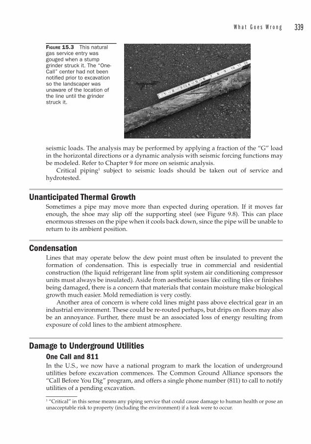
W h a t G o e s W r o n g 339
seismic loads. The analysis may be performed by applying a fraction of the “G” load in the horizontal directions or a dynamic analysis with seismic forcing functions may be modeled. Refer to Chapter 9 for more on seismic analysis.
Critical piping1 subject to seismic loads should be taken out of service and hydrotested.
Unanticipated Thermal Growth Sometimes a pipe may move more than expected during operation. If it moves far enough, the shoe may slip off the supporting steel (see Figure 9.8). This can place enormous stresses on the pipe when it cools back down, since the pipe will be unable to return to its ambient position.
CondensationLines that may operate below the dew point must often be insulated to prevent the formation of condensation. This is especially true in commercial and residential construction (the liquid refrigerant line from split system air conditioning compressor units must always be insulated). Aside from aesthetic issues like ceiling tiles or finishes being damaged, there is a concern that materials that contain moisture make biological growth much easier. Mold remediation is very costly.
Another area of concern is where cold lines might pass above electrical gear in an industrial environment. These could be re-routed perhaps, but drips on floors may also be an annoyance. Further, there must be an associated loss of energy resulting from exposure of cold lines to the ambient atmosphere.
Damage to Underground UtilitiesOne Call and 811 In the U.S., we now have a national program to mark the location of underground utilities before excavation commences. The Common Ground Alliance sponsors the “Call Before You Dig” program, and offers a single phone number (811) to call to notify utilities of a pending excavation.
1 “Critical” in this sense means any piping service that could cause damage to human health or pose an unacceptable risk to property (including the environment) if a leak were to occur.
FIGURE 15.3 This natural gas service entry was gouged when a stump grinder struck it. The “One-Call” center had not been notifi ed prior to excavation so the landscaper was unaware of the location of the line until the grinder struck it.
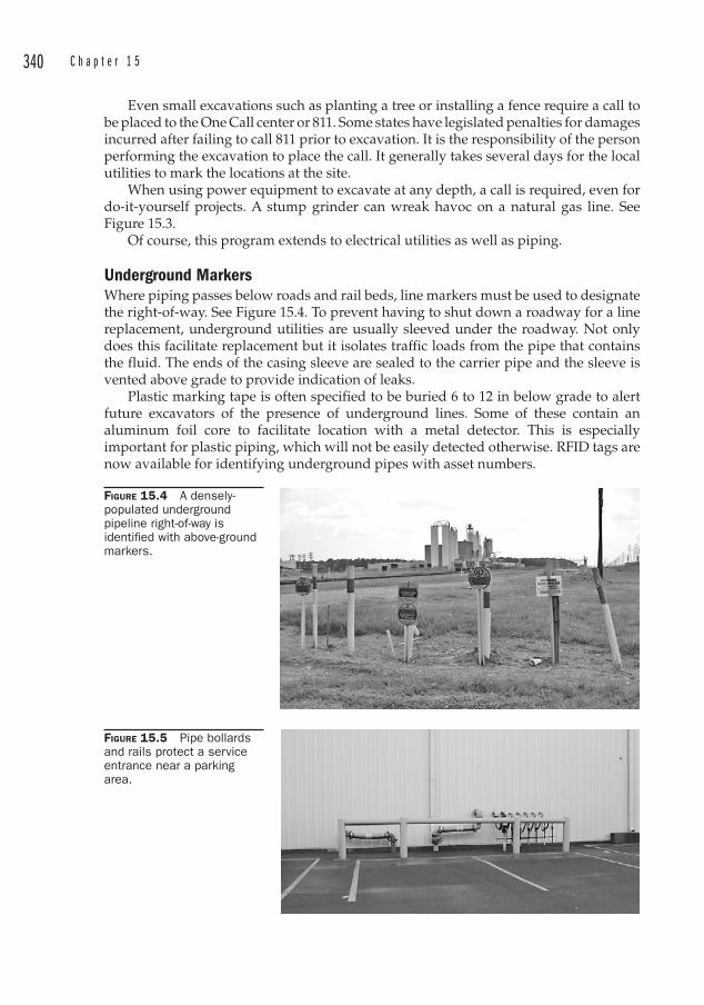
340 C h a p t e r 1 5
Even small excavations such as planting a tree or installing a fence require a call to be placed to the One Call center or 811. Some states have legislated penalties for damages incurred after failing to call 811 prior to excavation. It is the responsibility of the person performing the excavation to place the call. It generally takes several days for the local utilities to mark the locations at the site.
When using power equipment to excavate at any depth, a call is required, even for do-it-yourself projects. A stump grinder can wreak havoc on a natural gas line. See Figure 15.3.
Of course, this program extends to electrical utilities as well as piping.
Underground Markers Where piping passes below roads and rail beds, line markers must be used to designate the right-of-way. See Figure 15.4. To prevent having to shut down a roadway for a line replacement, underground utilities are usually sleeved under the roadway. Not only does this facilitate replacement but it isolates traffic loads from the pipe that contains the fluid. The ends of the casing sleeve are sealed to the carrier pipe and the sleeve is vented above grade to provide indication of leaks.
Plastic marking tape is often specified to be buried 6 to 12 in below grade to alert future excavators of the presence of underground lines. Some of these contain an aluminum foil core to facilitate location with a metal detector. This is especially important for plastic piping, which will not be easily detected otherwise. RFID tags are now available for identifying underground pipes with asset numbers.
FIGURE 15.4 A densely-populated underground pipeline right-of-way is identifi ed with above-ground markers.
FIGURE 15.5 Pipe bollards and rails protect a service entrance near a parking area.
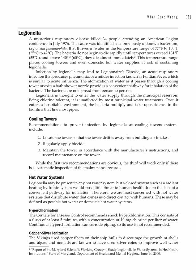
W h a t G o e s W r o n g 341
Legionella A mysterious respiratory disease killed 34 people attending an American Legion conference in July 1976. The cause was identified as a previously unknown bacterium, Legionella pneumophila, that thrives in water in the temperature range of 77°F to 108°F (25°C to 42°C). The bacteria do not begin to die rapidly until temperatures exceed 131°F (55°C), and above 140°F (60°C), they die almost immediately2. This temperature range places cooling towers and even domestic hot water supplies at risk of sustaining legionella.
Infection by legionella may lead to Legionnaire’s Disease, an acute respiratory infection that produces pneumonia, or a milder infection known as Pontiac Fever, which is similar to acute influenza. The atomization of water as it passes through a cooling tower or exits a bath shower nozzle provides a convenient pathway for inhalation of the bacteria. The bacteria are not spread from person to person.
Legionella is thought to enter the water supply through the municipal reservoir. Being chlorine tolerant, it is unaffected by most municipal water treatments. Once it enters a hospitable environment, the bacteria multiply and take up residence in the biofilms that line most pipes.
Cooling Towers Recommendations to prevent infection by legionella at cooling towers systems include:
1. Locate the tower so that the tower drift is away from building air intakes.
2. Regularly apply biocide.
3. Maintain the tower in accordance with the manufacturer’s instructions, and record maintenance on the tower.
While the first two recommendations are obvious, the third will work only if there is a systematic inspection of the maintenance records.
Hot Water Systems Legionella may be present in any hot water system, but a closed system such as a radiant heating hydronic system would pose little threat to human health due to the lack of a convenient pathway for inhalation. Therefore, we are most concerned with hot water systems that distribute water that comes into direct contact with humans. These may be defined as potable hot water or domestic hot water systems.
Hyperchlorination The Centers for Disease Control recommends shock hyperchlorination. This consists of a flush of at least 5 minutes with a concentration of 10 mg chlorine per liter of water. Continuous hyperchlorination can corrode piping, so its use is not recommended.
Copper-Silver Ionization The Vikings used copper fibers on their ship hulls to discourage the growth of shells and algae, and nomads are known to have used silver coins to improve well water 2 “Report of the Maryland Scientific Working Group to Study Legionella in Water Systems in Healthcare Institutions,” State of Maryland, Department of Health and Mental Hygiene, June 14, 2000.
342 C h a p t e r 1 5
quality. Since the 1950s, copper-silver ionization techniques have been used for water disinfection. This technique has been applied in hospitals to reduce the growth of Legionella .
The ionization of the metals occurs through electrolysis and forms positively charged copper (Cu+ and Cu2+) and silver (Ag+) ions. Because chlorine is not required, this technique was used to disinfect water for NASA’s space program.
Ultraviolet Radiation UV radiation has been applied successfully to municipal water systems to eliminate legionella. UV disinfection of drinking water was first used in the U.S. in 1916. The disinfection occurs because the UV radiation penetrates the cell walls of bacteria and disrupts its ability to reproduce.
Compared to chemical treatments, UV radiation offers no residual disinfection capabilities. There are no chemical residues carried downstream to continue to act on the bacteria. This may be viewed either as a positive or negative aspect of UV treatment.
Monochloramine Monochloramine has been used for some time as a disinfectant in public water supplies. Studies prepared by the CDC3 indicate that monochloramine performs better at eliminating legionella than traditional chlorine doses.
TemperatureAnother way of eliminating and preventing legionella from inhabiting a domestic or potable hot water system is by elevating the temperature above 140°F (60°C). Chemical treatments such as chlorine shocks are deemed to be ineffective against existing colonies of legionella due to their inability to penetrate the biofilms that line most pipes. The risk of scalding has discouraged facilities from operating domestic hot water systems above 120°F (49°C). But this lies within the range of temperatures at which legionella thrive. So if the temperatures must be elevated to 140°F (60°C), ASSE anti-scald devices must be installed at the points-of-use.
Operator Error Petrochemical plants have a higher level of technical training than other facilities in general industry. The facilities that rely on the common knowledge of their operations and maintenance staff should realize that such knowledge is rarely common. Training should be provided to teach personnel how to recognize when a valve is open or closed.
Emergency shut-off valves should be represented diagrammatically on sketches throughout facilities and the valves should be labeled. Curb valve wrenches need to be stored conveniently and a maintenance schedule should be developed to exercise these valves.
It is also important to inspect fire protection valves. Technicians that perform backflow preventer inspections will sometimes accidentally leave a main valve in the closed position. A facility manager that simply accepts the inspector’s report, and 3 B. Flannery, L.B. Gelling, D.J. Vugia, J.M. Weintraub, J.J. Salerno, M.J. Conroy, et al. Reducing Legionella colonization of water systems with monochloramine. Available from http://www.cdc.gov/ncidod/EID/vol12no04/05-1101.htm.
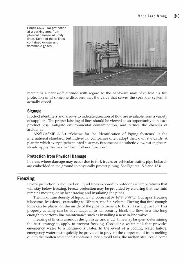
W h a t G o e s W r o n g 343
maintains a hands-off attitude with regard to the hardware may have lost his fire protection until someone discovers that the valve that serves the sprinkler system is actually closed.
Signage Product identifiers and arrows to indicate direction of flow are available from a variety of suppliers. The proper labeling of lines should be viewed as an opportunity to reduce product loss, mitigate environmental contamination, and reduce the chances of accidents.
ANSI/ASME A13.1 “Scheme for the Identification of Piping Systems” is the international standard, but individual companies often adopt their own standards. A plant in which every pipe is painted blue may fit someone’s aesthetic view, but engineers should apply the maxim “form follows function.”
Protection from Physical DamageIn areas where damage may occur due to fork trucks or vehicular traffic, pipe bollards are embedded in the ground to physically protect piping. See Figures 15.5 and 15.6.
FreezingFreeze protection is required on liquid lines exposed to outdoor air temperatures that will stay below freezing. Freeze protection may be provided by ensuring that the fluid remains moving, or by heat tracing and insulating the pipes.
The maximum density of liquid water occurs at 39.16°F (3.98°C). But upon freezing it becomes less dense, expanding to 109 percent of its volume. During that time enough force can be placed on the inside of the pipe to cause it to burst, as in Figure 15.7 This property actually can be advantageous to temporarily block the flow in a line long enough to perform line maintenance such as installing a new in-line valve.
Freezing of lines is a serious design issue, and much time may be spent determining the best strategy to apply to prevent freezing. Consider a water tank that provides emergency water to a continuous caster. In the event of a cooling water failure, emergency water must quickly be provided to prevent the copper mold from melting due to the molten steel that it contains. Once a mold fails, the molten steel could come
FIGURE 15.6 No protection at a parking area from physical damage of utility lines. Some of these lines contained oxygen and fl ammable gases.
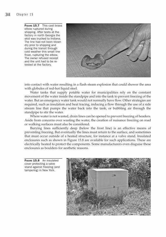
344 C h a p t e r 1 5
into contact with water resulting in a flash steam explosion that could shower the area with globules of red-hot liquid steel.
Water tanks that supply potable water for municipalities rely on the constant movement of the water inside the standpipe and into the tank to prevent freezing of the water. But an emergency water tank would not normally have flow. Other strategies are required, such as insulation and heat tracing, inducing a flow through the use of a side stream line that pumps the water back into the tank, or bubbling air through the standpipe to stir the water.
Where water is not wasted, drain lines can be opened to prevent freezing of headers. Aside from concerns over wasting the water, the creation of nuisance freezing on road or walking surfaces must also be considered.
Burying lines sufficiently deep (below the frost line) is an effective means of preventing freezing. But eventually the lines must return to the surface, and sometimes that must occur outside of a heated structure, for instance at a valve stand. Insulated enclosures such as shown in Figure 15.8 are available for such applications. These are electrically heated to protect the components. Some manufacturers even disguise these enclosures as boulders for aesthetic reasons.
FIGURE 15.7 This cast brass elbow ruptured during shipping. After tests at the factory in north Georgia the skid was trucked to Indiana. The line had not been blown dry prior to shipping and during the transit through cold weather this small line froze, rupturing the elbow. The owner refused receipt and the unit had to be re-tested at the factory.
FIGURE 15.8 An insulated cover protecting a valve stand against freezing (and tampering) in New York.
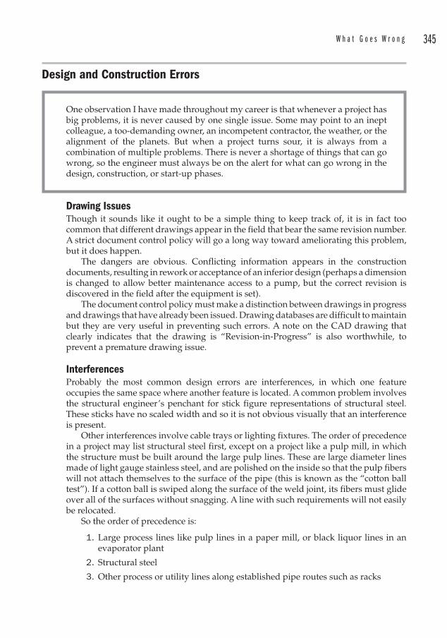
W h a t G o e s W r o n g 345
Design and Construction Errors
One observation I have made throughout my career is that whenever a project has big problems, it is never caused by one single issue. Some may point to an inept colleague, a too-demanding owner, an incompetent contractor, the weather, or the alignment of the planets. But when a project turns sour, it is always from a combination of multiple problems. There is never a shortage of things that can go wrong, so the engineer must always be on the alert for what can go wrong in the design, construction, or start-up phases.
Drawing IssuesThough it sounds like it ought to be a simple thing to keep track of, it is in fact too common that different drawings appear in the field that bear the same revision number. A strict document control policy will go a long way toward ameliorating this problem, but it does happen.
The dangers are obvious. Conflicting information appears in the construction documents, resulting in rework or acceptance of an inferior design (perhaps a dimension is changed to allow better maintenance access to a pump, but the correct revision is discovered in the field after the equipment is set).
The document control policy must make a distinction between drawings in progress and drawings that have already been issued. Drawing databases are difficult to maintain but they are very useful in preventing such errors. A note on the CAD drawing that clearly indicates that the drawing is “Revision-in-Progress” is also worthwhile, to prevent a premature drawing issue.
InterferencesProbably the most common design errors are interferences, in which one feature occupies the same space where another feature is located. A common problem involves the structural engineer’s penchant for stick figure representations of structural steel. These sticks have no scaled width and so it is not obvious visually that an interference is present.
Other interferences involve cable trays or lighting fixtures. The order of precedence in a project may list structural steel first, except on a project like a pulp mill, in which the structure must be built around the large pulp lines. These are large diameter lines made of light gauge stainless steel, and are polished on the inside so that the pulp fibers will not attach themselves to the surface of the pipe (this is known as the “cotton ball test ”). If a cotton ball is swiped along the surface of the weld joint, its fibers must glide over all of the surfaces without snagging. A line with such requirements will not easily be relocated.
So the order of precedence is:
1. Large process lines like pulp lines in a paper mill, or black liquor lines in an evaporator plant
2. Structural steel
3. Other process or utility lines along established pipe routes such as racks
346 C h a p t e r 1 5
4. Electrical cable trays
5. Piping drops to equipment
6. Electrical drops to equipment
Very often the real estate will be carved out at the beginning of a project, establishing at what elevations the piping and electrical routings will occur. This saves a lot of trouble since it eliminates the need to cross-check between disciplines within that elevation envelope.
Contractor Errors
I once provided some preliminary, undimensioned mechanical room concept layouts to my contractor client who wanted to review progress and comment on the layout. During a site visit later in the week, I saw the foreman hovering over the 11 � 17s in the mechanical room, holding a ruler to the drawings. Chalk outlines appeared on the floor.
“What are you doing?” I asked nervously.“Laying out the pumps and chillers,” came his matter-of-fact reply.“Those drawings aren’t issued for construction,” I explained.He had been scaling a reduced-sized drawing with a 6-in flexible ruler with
markings in sixteenths of an inch. An unchecked drawing. It was an opportunity for error piled on top of error, so I waved them off until I could provide checked, dimensioned drawings that could physically accommodate the space constraints and the piping configuration.
Contractors are always eager to get started with construction and they may be too eager. On occasion they need to be reined in.
The desire to reduce costs can manifest itself in too little field trim being left on prefabbed pipe spools . Another problem that can occur is excessive out-of-tolerance on setting structural steel. Columns have been set as much as 2 in off from where they were designed. Since piping is referenced to column lines in plans, any deviation from where the structural members were intended can accumulate and cause problems with piping alignment.
Coordination with other disciplines (as described in Chapter 10) is an ongoing process. But even the diligent review of other discipline’s drawings may not catch errors like conduit being field-routed across intended access points. Early detection by knowledgeable field engineers and construction managers is required, because once a cable tray or conduit is full of wires, few possess the temerity to demand relocating it.
347
CHAPTER 16Special Services
Natural Gas Natural gas is essentially methane, which has a heat of combustion of approximately 1000 BTU/ft3. The supplying utility can provide detailed information regarding the exact constituents in the supply gas, as well as an accurate heat of combustion. Methane is an odorless, colorless gas, so the utilities add an odorant , often tert-butyl mercaptan to the stream to provide ready indication of leaks.
To provide natural gas to a continuous casting operation in a steel mill, the vendor recommended passing the gas stream through a water seal as a measure to prevent backflashing. One of the engineers for the company I worked for discounted this as an unsafe practice, claiming that water would absorb the odorant . Additional research indicated that the mercaptan is not soluble in water, and therefore would be unaffected by passing the gas stream through a water seal.
We decided not to use the water seal anyway, since we judged the chance of oxygen entering the natural gas piping to be acceptably low. Unless oxygen is mixed inside the gas pipe, there is no chance of explosion. This may not be the case with burning torches however, which should always be equipped with backflash arrestors.
The natural gas infrastructure is routed cross-country using steel or plastic piping. Plastic piping requires a copper tracer to be buried with the pipe. The pressure is often stepped down at the user through a pressure reducing valve that is equipped with a vent to atmosphere. While these reducing valves are usually located outside, it may be convenient at times to locate them inside a facility, in which case the vent must be piped outside1 unless the regulator is equipped with and labeled for utilization with an approved vent-limiting device. Attention should be paid at the beginning of a project to determine whether it is worthwhile to provide a lower pressure header system or have many penetrations through the building roof or walls for each of the vents.
Piping to individual appliances must be supplied with a shut-off valve in the same room, and below that, a dirt leg to catch particles and prevent them from fouling the burner orifices. The dirt leg utilizes a tee to make the bend from vertical to horizontal and has a nipple with a cap extending below the tee.
The gas piping must be protected from physical damage. Except for devices that must be piped up and then moved into place (for example, a gas clothes dryer or gas range), the piping should be rigid, although it has become common to see flex connectors 1 2003 International Fuel Gas Code, Paragraph 410.3, “Venting of regulators.”
348 C h a p t e r 1 6
used for appliance hook-ups in stationary installations (water heaters, gas-fired unit heaters), since it alleviates the contractor from having to make an exacting rigid fit-up.
Plastic gas piping must never be used above ground2 unless it is:
• Terminated outside in a riser specially made for that application (an “anodeless riser”)
• Terminated with a wall head adapter inside a building3
Capacity of Natural Gas PipelinesAn equation to determine the capacity of a gas line is provided by The Institute of Gas Technology. It is applicable for pressures between 5 and 60 psig and pipe sizes between 2 and 20 in.
Q 3501p p
LD2
212
2.667��⎛
⎝⎜
⎞
⎠⎟
0 556.
(Equation 16.1)
where Q � Flow [ft3/hour] p � Pressure [psia] L � Length [ft] D � Inside diameter [in]
Sealing Natural Gas T hreaded Connections
During a trip to one of the big box stores I noticed a variety of PTFE (Teflon®) tape available in different colors. I asked someone what the difference was and was told that the different colors are intended for different services. A comparison of the labels indicated no difference in materials, so I was at a loss as to the applications. I checked a few plumbing forums online, and learned that the knowledge base regarding Teflon® tape i s minimal.
It seems that some of the colors like yellow (which is intended for fuel gas) are thicker, but the literature incorrectly identifies this as “denser.” So if the only difference is that the tape is thicker, it seems like one could apply more wraps to the joint.
There are hundreds of thousands of low-pressure natural gas joints performing satisfactorily with only the application of white PTFE tape on the joint. There is not much technique to applying tape to a joint, other than:
• The tape should be wrapped in the direction of the threads so that it does not loosen as the joint is started.
• The tape should not be permitted to enter the inside of the pipe.
Therefore, whether the installer takes 2 or 10 wraps, the various codes and inspectors do not care. All that matters is that a leak-tight joint is made. Manufacturers of the yellow tape claim it is shred-resistant. Pipe dope may also be used on gas pipe threads.
2 Ibid, Paragraph 404.14.1.3 The wall head adapter is a transition (from plastic to steel) fitting that permits new plastic tubing to be fed through a foundation wall. The fitting attaches to the steel pipe and terminates the plastic tubing within the fitting on the interior side of the wall. Since many gas utilities now prefer the transition to steel be made outside the building with an anodeless riser, they move their meters outside for easy access. This makes the use of these wall head adapters infrequent.
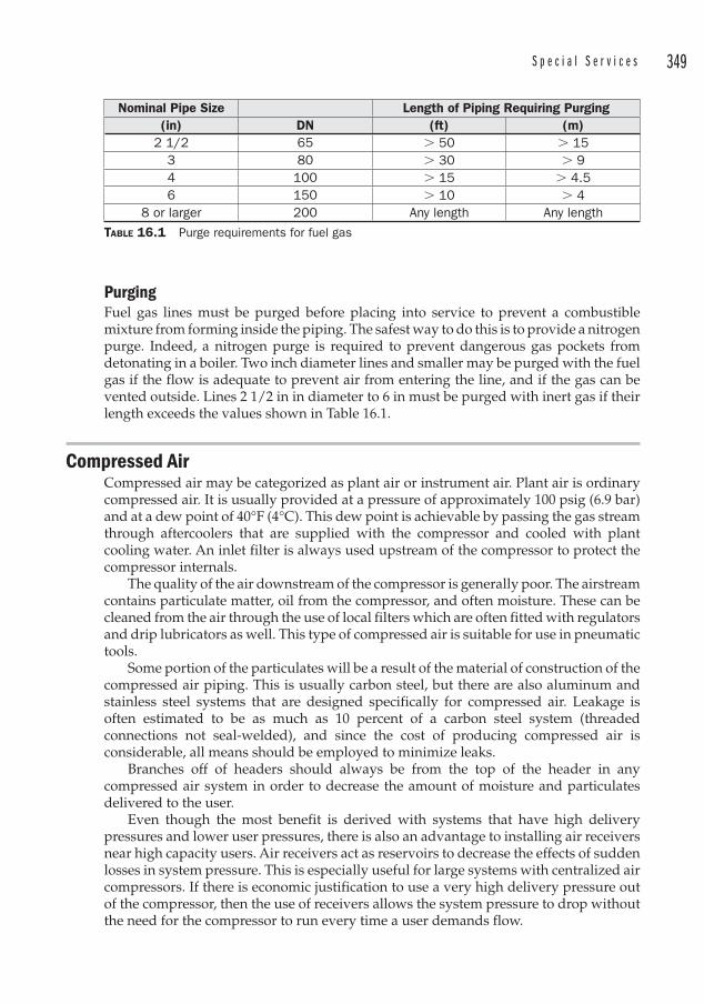
S p e c i a l S e r v i c e s 349
PurgingF uel gas lines must be purged before placing into service to prevent a combustible mixture from forming inside the piping. The safest way to do this is to provide a nitrogen purge. Indeed, a nitrogen purge is required to prevent dangerous gas pockets from detonating in a boiler. Two inch diameter lines and smaller may be purged with the fuel gas if the flow is adequate to prevent air from entering the line, and if the gas can be vented outside. Lines 2 1/2 in in diameter to 6 in must be purged with inert gas if their length exceeds the values shown in Table 16.1.
Compressed AirC ompressed air may be categorized as plant air or instrument air. Plant air is ordinary compressed air. It is usually provided at a pressure of approximately 100 psig (6.9 bar) and at a dew point of 40°F (4°C). This dew point is achievable by passing the gas stream through aftercoolers that are supplied with the compressor and cooled with plant cooling water. An inlet filter is always used upstream of the compressor to protect the compressor internals.
The quality of the air downstream of the compressor is generally poor. The airstream contains particulate matter, oil from the compressor, and often moisture. These can be cleaned from the air through the use of local filters which are often fitted with regulators and drip lubricators as well. This type of compressed air is suitable for use in pneumatic tools.
Some portion of the particulates will be a result of the material of construction of the compressed air piping. This is usually carbon steel, but there are also aluminum and stainless steel systems that are designed specifically for compressed air. Leakage i s often estimated to be as much as 10 percent of a carbon steel system (threaded connections not seal-welded), and since the cost of producing compressed air is considerable, all means should be employed to minimize leaks.
Branches off of headers should always be from the top of the header in any compressed air system in order to decrease the amount of moisture and particulates delivered to the user.
Even though the most benefit is derived with systems that have high delivery pressures and lower user pressures, there is also an advantage to installing air receivers near high capacity users. Air receivers act as reservoirs to decrease the effects of sudden losses in system pressure. This is especially useful for large systems with centralized air compressors. If there is economic justification to use a very high delivery pressure out of the compressor, then the use of receivers allows the system pressure to drop without the need for the compressor to run every time a user demands flow.
Nominal Pipe Size Length of Piping Requiring Purging(in) DN (ft) (m)
2 1/2 65 � 50 � 153 80 � 30 � 94 100 � 15 � 4.56 150 � 10 � 4
8 or larger 200 Any length Any length
TABLE 16.1 Purge requirements for fuel gas
350 C h a p t e r 1 6
Instrument AirI nstrument-quality air is required for “cleaner” applications such as pneumatic controls and instruments that are used in HVAC controls and to operate diaphragms in control valve operators. The International Society of Automation provides a standard in conjunction with ANSI for defining the quality of an airstream to be used for instrument air. This standard is ANSI/ISA 7.0.01 “ Quality Standard for Instrument Air.” This standard limits moisture content, entrained particle size and oil content, standard air supply pressures, ranges of pneumatic transmission signals, and criteria for testing compliance with instrument-quality air standards.
The basic requirements for instrument air are:
1. The dew point for instrument air (if the system is completely indoors) is limited to 35°F (2°C) although it is usually specified to be –40°F (–40°C). In any case, the dew point must be 18°F (10°C) below the lowest temperature to which any part of the system might be exposed.
2. The particulate size is limited to 0.00012 in (3 micron). 3. The oil content is limited to 1 ppm, but shall be as close to zero as possible.
Some compressors are oil-free, so this is not difficult to achieve. 4. There are to be no corrosive or hazardous gases present in the airstream. 5. The operating pressures are generally 15 to 50 psig (1.0 to 3.4 bar).
The trend in industry is to provide instrument quality air for both instruments and general compressed air. This prevents deterioration of the air piping due to the high moisture content, and prevents the need for two separate systems.
Compressed air systems should be provided with a tee on the main header and a valve to the outside of the building along a road, so that whenever supplemental air is needed it can easily be connected. Rental air compressors are extremely useful for this, and during the lifetime of the plant may be required at start-up, or during maintenance to one of the main compressors.
The compressors will most likely require cooling water, so they may not be available at start-up because the cooling water system may need air to regulate the control valves. To sidestep this chicken-and-egg problem, an air-cooled compressor may be rented and connected to the tee in the main header.
Compressed air systems will be full of bits of dirt, mill scale, and oil. During commissioning, the headers should be blown down to eliminate as much of this as possible. Some specifications call for a target to be made out of a board painted white, and for the air to be blown at the board. Through successive trials, the number of particles decreases to an acceptable level.
Like pump systems, compressors are often sized according to “N+1,” where N is the number of compressors required to operate the system, and the extra compressor is down for maintenance, or available as an in-line spare.
Oxygen
A steel mill in Alabama wanted to replace some very special valves in a lime conveying system. The lime was pneumatically conveyed into Basic Oxygen F urnaces using oxygen, since the furnaces need both lime for slag production and
S p e c i a l S e r v i c e s 351
oxygen for increasing the combustion of the fuel and to lower the carbon content. When I learned that the conveying medium was oxygen, I wondered if they had any devices in place to prevent stones, iron nuts or bolts, or whatever else might find its way into a bulk lime delivery and create a spark inside the steel pipe. They had nothing like that.
I explained to them that this was a risky operation, since the presence of a spark inside a high-oxygen atmosphere was likely to cause a fire. Fires fed by high-pressure oxygen are exceedingly dangerous. But this mill had had experience operating in this fashion for 30 or more years and they were comfortable with the situation.
Oxygen i s one of the most hazardous fluid services to deal with. Oxygen supports combustion and a fire fed by high-pressure oxygen will be spectacular and deadly. Oxygen systems must be free of grease or oil, since the heat of compression alone may be sufficient to ignite the organic fuel. Particulates inside the pipe could cause a spark which could lead to ignition and burning of the metal pipe. Impingement is also a concern, as when the flow enters from the branch of a tee. The risks of creating a spark are reduced if the velocity is kept below 100 fps. Once ignited, the fire will burn even the carbon steel pipe that is usually used to contain oxygen systems.
The Compressed Gas Association standard CGA G-4.4 “ Industrial Practices for Gaseous Oxygen T ransmission and Distribution Piping Systems” details acceptable practices for the design of oxygen piping systems. The reader is encouraged to carefully review those recommendations, some of which follow.
1. When ordering valves, the purchaser must specify that the valves are for oxygen service. Such valves must be specially cleaned and kept free of oil or grease.
2. For carbon steel piping, the design velocity of oxygen must be kept below 200 ft per second (61 m/sec) for pressures below 200 psig (13.8 bar). The reason for this is to reduce the chance of ignition by particles impacting the inside of the pipe. Copper, stainless steel, and nickel alloys may be subjected to higher velocities. Aluminum and aluminum alloys should never be used.
3. Lengths of copper piping are sometimes installed in a carbon steel system as fire stops. The thinking is that if the carbon steel catches on fire, the fire will not spread upstream of the copper, since copper (as well as nickel, Monel, tin bronze, and Inconel) resists burning.
4. As an economical consideration, carbon steel is safe to use in oxygen systems, but it is best to use stainless steel tees where the flow is into the tee from the branch leg (a side entrance tee). This again is because of the desire to limit the chances of ignition due to impingement by foreign particles.
5. A system is considered clean for oxygen service once all internal organic, inorganic, and particulates have been removed. Internal welding slag and spatter should be mitigated through the use of TIG welds o n root welds.
Oxy-Fuel CuttingW here utility drops are provided for the convenience of maintenance in a facility, consideration must be given to the chances of connecting pneumatic equipment to an oxygen drop. A pneumatic hammer that contains oil could explode into flames if
352 C h a p t e r 1 6
connected to an oxygen supply. Therefore, the inadvertent connection must be prevented by signage and the use of different hose connections for the different uses.
Sample end connections for a utility drop:
• Natural gas d rops equipped with an on-off valve which has a ½ in NPT male inlet and a Type ‘C’ 7/8-14 LH male thread. This will connect to a natural gas regulator which has the mating female thread. The outlet of the regulator will be a Type ‘B’ 9/16-18 LH male thread, for direct connection to a torch hose. These are known as CGA 025 connections.
• Oxygen d rops equipped with an on-off valve which has a 1/2 in NPT male inlet and a Type ‘C’ 7/8-14 RH male thread. This will connect to an oxygen regulator which has the mating female thread. The outlet of the regulator will be a Type ‘B’ 9/16-18 RH male thread, for direct connection to a torch hose. These are known as CGA 024 connections.
• Compressed air d rops equipped with a ball valve. The end connection will be a “twist-to-connect” connection with a locking pin.
Burning torches have the appropriate connecting nuts for attachment to the natural gas and oxygen regulators. The oxygen hoses are green and the nuts are RH threaded and are smooth. The fuel gas hoses are red, the nuts are LH threaded and have dimples on the corners.
It should be noted that where on-off valves are threaded, these safety measures can be defeated by a determined individual with a wrench. A typical utility drop is shown in Figure 16.1.
Oxygen s ystems should be pressure tested only with clean dry “instrument-quality” air or an inert gas like nitrogen. Compressed air will leave an oil residue, and water will cause corrosion and may contain chemicals that could react with the oxygen.
FIGURE 16.1 A typical utility drop with valves and identifi cation of services.
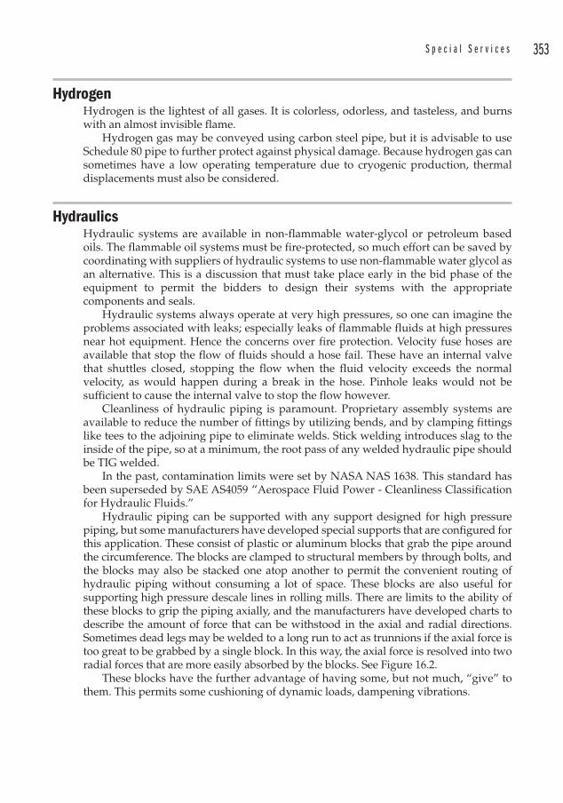
S p e c i a l S e r v i c e s 353
HydrogenH ydrogen i s the lightest of all gases. It is colorless, odorless, and tasteless, and burns with an almost invisible flame.
Hydrogen g as may be conveyed using carbon steel pipe, but it is advisable to use Schedule 80 pipe to further protect against physical damage. Because hydrogen gas can sometimes have a low operating temperature due to cryogenic production, thermal displacements must also be considered.
HydraulicsHydraulic systems a re available in non-flammable water-glycol or petroleum based oils. The flammable oil systems must be fire-protected, so much effort can be saved by coordinating with suppliers of hydraulic systems to use non-flammable water glycol as an alternative. This is a discussion that must take place early in the bid phase of the equipment to permit the bidders to design their systems with the appropriate components and seals.
Hydraulic systems a lways operate at very high pressures, so one can imagine the problems associated with leaks; especially leaks of flammable fluids at high pressures near hot equipment. Hence the concerns over fire protection. Velocity fuse hoses are available that stop the flow of fluids should a hose fail. These have an internal valve that shuttles closed, stopping the flow when the fluid velocity exceeds the normal velocity, as would happen during a break in the hose. Pinhole leaks would not be sufficient to cause the internal valve to stop the flow however.
Cleanliness of hydraulic piping is paramount. Proprietary assembly systems are available to reduce the number of fittings by utilizing bends, and by clamping fittings like tees to the adjoining pipe to eliminate welds. Stick welding introduces slag to the inside of the pipe, so at a minimum, the root pass of any welded hydraulic pipe should be TIG welded.
In the past, contamination limits were set by NASA NAS 1638. This standard has been superseded by SAE AS4059 “ Aerospace Fluid Power - Cleanliness Classification for Hydraulic Fluids.”
Hydraulic piping can be supported with any support designed for high pressure piping, but some manufacturers have developed special supports that are configured for this application. These consist of plastic or aluminum blocks that grab the pipe around the circumference. The blocks are clamped to structural members by through bolts, and the blocks may also be stacked one atop another to permit the convenient routing of hydraulic piping without consuming a lot of space. These blocks are also useful for supporting high pressure descale l ines in rolling mills. There are limits to the ability of these blocks to grip the piping axially, and the manufacturers have developed charts to describe the amount of force that can be withstood in the axial and radial directions. Sometimes dead legs may be welded to a long run to act as trunnions if the axial force is too great to be grabbed by a single block. In this way, the axial force is resolved into two radial forces that are more easily absorbed by the blocks. See Figure 16.2.
These blocks have the further advantage of having some, but not much, “give” to them. This permits some cushioning of dynamic loads, dampening vibrations.
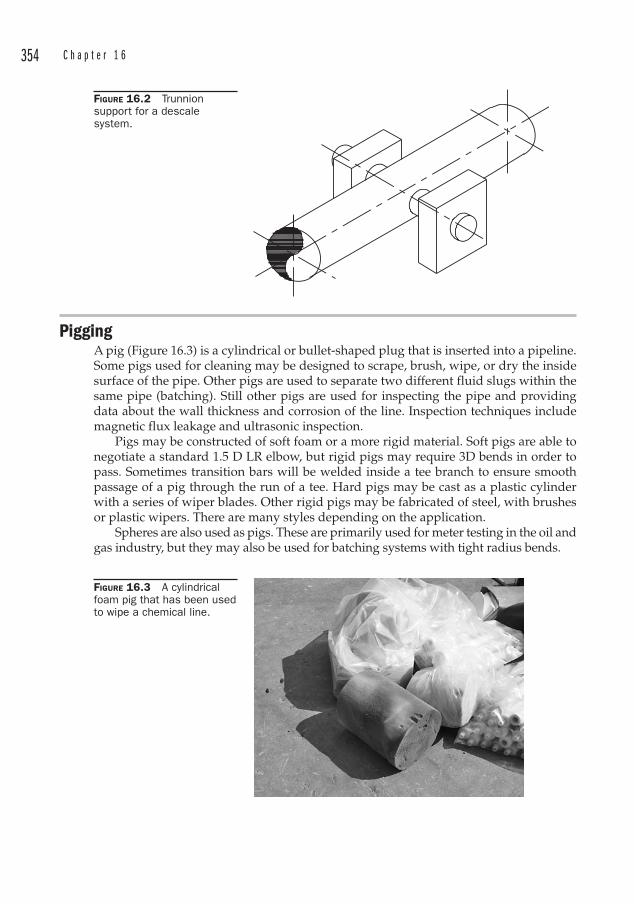
354 C h a p t e r 1 6
PiggingA pig ( Figure 16.3) is a cylindrical or bullet-shaped plug that is inserted into a pipeline. Some pigs used for cleaning may be designed to scrape, brush, wipe, or dry the inside surface of the pipe. Other pigs are used to separate two different fluid slugs within the same pipe (batching). Still other pigs are used for inspecting the pipe and providing data about the wall thickness and corrosion of the line. Inspection techniques include magnetic flux leakage a nd ultrasonic i nspection.
Pigs may be constructed of soft foam or a more rigid material. Soft pigs are able to negotiate a standard 1.5 D LR elbow, but rigid pigs may require 3D bends in order to pass. Sometimes transition bars will be welded inside a tee branch to ensure smooth passage of a pig through the run of a tee. Hard pigs may be cast as a plastic cylinder with a series of wiper blades. Other rigid pigs may be fabricated of steel, with brushes or plastic wipers. There are many styles depending on the application.
Spheres are also used as pigs. These are primarily used for meter testing in the oil and gas industry, but they may also be used for batching systems with tight radius bends.
FIGURE 16.2 Trunnion support for a descale system.
FIGURE 16.3 A cylindrical foam pig that has been used to wipe a chemical line.
355
CHAPTER 17Infrastructure
Piping engineering seems like a mundane topic to the population-at-large. Laying out a piping system is certainly not as exciting as designing something like the Akashi-Kaikyo bridge in Japan, the Burj Dubai, or a subatomic particle accelerator. Public sentiment regarding piping design may be summed up as “out-of-sight, out-of-mind.”
Yet the mechanical or chemical engineer who has driven around East Houston cannot help but be impressed with the maze of piping that controls the landscape. The sympathetic engineer’s pulse quickens and the mind reels in appreciation of the sheer number of drawings that must have been required to produce such an array of piping.
The business of satisfying the world’s thirst for energy is the business of extracting resources from underground, processing them into a usable product, and delivering them to the consumer.
But there is another more literal thirst that must be satisfied by every living creature: drinkable water. The demands placed on potable water resources have already led to legal actions, and some quarters feel that it does not stretch the imagination to think that future wars will be waged over water rights.
All the more reason to select materials and design systems to utilize the resources efficiently.
Infrastructure Infrastructure generally refers to the network of engineering works that sustain activity in a modern society. This includes highways and the distribution of utilities. We will isolate our discussion to utilities other than electrical.
On a discrete level, this may be the engineering works required to provide utilities within the boundaries of a steel-making facility. On a more macroscopic level it may be the systems that provide water, steam, and sewage disposal to an entire region.
When one is starting with a clean sheet of paper, many desired features can be incorporated within the limits of schedule, budget, and the cleverness of the engineer or owner. A far greater challenge is dealing with existing infrastructure. Interferences with other utilities, settling of the supporting soil, and access for something as simple as inspection are some issues that the engineer must face when modifying or operating the aging infrastructure in most developed countries. Failure prediction is not an exact science as applied to utility piping, since so much of it is buried.
• A steam explosion in Manhattan on July 18, 2007 killed one person and injured dozens more. The crater near Grand Central Station swallowed a tow truck. The steam line was installed in 1924 and was determined to have failed due to a
356 C h a p t e r 1 7
water hammer event triggered by a failed steam trap. At least 12 other steam pipe explosions have occurred in New York City since 1987.
• A 36 in cast iron water main (that was located directly under the recently re-paved Fort Duquesne Boulevard) failed in August 2005 in downtown Pittsburgh, Pennsylvania, flooding the basements of local buildings and parking garages. The line was 90 years old, and had been rehabilitated with a cement lining in 1986.
The rehabilitation of aging pipelines is obviously an issue that will only become increasingly important until these utility lines can be replaced in their entirety. It should be noted that the design life for modern industrial installations is usually set at 30 or 40 years. And even though many industrial installations are far older, few efficient systems are operating at 80 or 90 years old.
Diagnostic ToolsAside from seeing a puddle forming on the road, or hearing or smelling a gas leak, there are some sophisticated diagnostic tools available to detect leaks.
Acoustical Leak Detectors Sophisticated acoustical leak detectors are available at moderate prices to listen for the sound of fluids leaking from the pipe. Some are used as a sensitive wand that is walked over the route of the pipeline to listen for the leak. Others are connected to two end points of the pipeline. A correlator detects the sound of the leak at both ends of the pipe. The sound produced by the leak arrives at the nearer end first, and the time delay for the sound to arrive at the farther point is measured and entered into an algorithm to calculate the position of the leak.
Infrared Imaging Infrared (thermal) scans can be made from the ground or air to check for leaks. High resolution images may be obtained through the use of low-level flights over a pipeline as it travels cross-country. This can even determine the relative amount of leakage so that repairs can be prioritized.
Where the exact position of a pipeline is not known, a higher-level flight can be flown. Depending on ground cover, the pipe bed may be visible on the thermal scan a little over half of the time.
Infrared imaging can be very sensitive, and can indicate leaks before they would otherwise be obvious as ground water. This technique is used for steam and water, and may be applied to other liquids as well.
Smoke and Dye Detection Older municipalities often have combined storm and sewer systems. When it rains, it overwhelms the sewage treatment plants which causes flooding of raw sewage into rivers and streams. These municipalities are forced to eliminate storm water from the sanitary sewer systems.
Aside from large trunk lines that are interconnected below grade, another culprit is the connection of roof drains to the sanitary sewer system. Periodically the sewage authority will conduct smoke tests to determine if downspouts are connected to the sanitary sewer. They discharge a high-density smoke generator inside the sanitary sewer, and look around the neighborhood to observe smoke rising from downspouts. Offenders are warned to disconnect the downspouts from the sewer or face fines.
In some municipalities a dye test is required as part of a real estate transaction. A registered plumber is required to place a dye down any downspout that discharges
I n f r a s t r u c t u r e 357
below ground. The pipe is flooded with water, and a sanitary sewer manhole downstream is observed to see if there is any evidence of the dye. Observation of the dye fails the test, and the downspouts must be disconnected. If no dye is observed the plumber certifies that the downspouts are not connected to the sanitary sewer.
Disconnecting the downspouts is an easy task, but it should be noted that the downspouts should discharge onto splash blocks directed away from the foundation in order to prevent erosion and water penetration into the basement of structures.
Infiltration of ground water into the sanitary sewer is still another problem for sewage treatment plants. Older sewer lines are susceptible to leaks and infiltration, and trenchless technologies are sometimes employed to seal them.
Rehabilitation and Replacement of PipelinesAside from excavating and removing an existing line and then replacing it in total with a new pipe, there are technologies available to repair and replace lines without the expense of excavation. These are known as “trenchless technologies ” and the lining of pipes in place is described as “in situ” relining.
Problems with TrenchingTo begin with, any form of excavation requires knowing where other utilities are located. In the U.S., this requires a call to the national one call number 811. Canada also offers one-call response for utility identification.
Besides above ground markers for utility rights-of-way and buried plastic strips to warn excavators of the presence of underground utilities, RFID tags are now available to place on the piping to locate and uniquely identify the line with an asset number. These markers operate at a frequency between 65 and 135 kHz.
Trenchless technologies are suitable for replacement or rehabilitation of pipelines. But repairs generally require that a trench be opened for access. Many of these lines are far below grade and special precautions are required to ensure the safety of workers who enter these excavations. See Table 17.1.
Sloping of trenches is usually only available on greenfield sites. The trench slope is laid back at an angle shallower than the angle of repose of the soil. This often requires a wide right-of-way.
Cement Mortar Lining Piping may be lined with cement to protect against corrosion, reduce leaks, increase flow, or extend the life of the pipe. A thin coating, between 1/8 inch and 3/16 inch (approximately 4 mm) is flung against the sides of the pipe and is sometimes even troweled smooth.
The result is a layer of mortar that creates a zone of alkalinity against the wall of the pipe, neutralizing the pH of slightly acidic fluids that would normally accelerate corrosion of ferrous metals.
Cement exudes calcium hydroxide in the presence of moisture, so that if shrinkage cracks occur during setting, the calcium hydroxide fills and seals the cracks. This phenomenon is known as “autogenous healing. ”
Cured-In-Place Pipe (CIPP) ReliningOne method used to improve the interior surface of pipes and provide a corrosion-resistant interior is to apply an epoxy coating.1 This method is used primarily for hot and cold water systems. The basics steps are:1 Refer to ASTM F1743 “Standard Practice for Rehabilitation of Existing Pipelines and Conduits by Pulled-in-Place Installation of Thermosetting Resin Pipe (CIPP).”
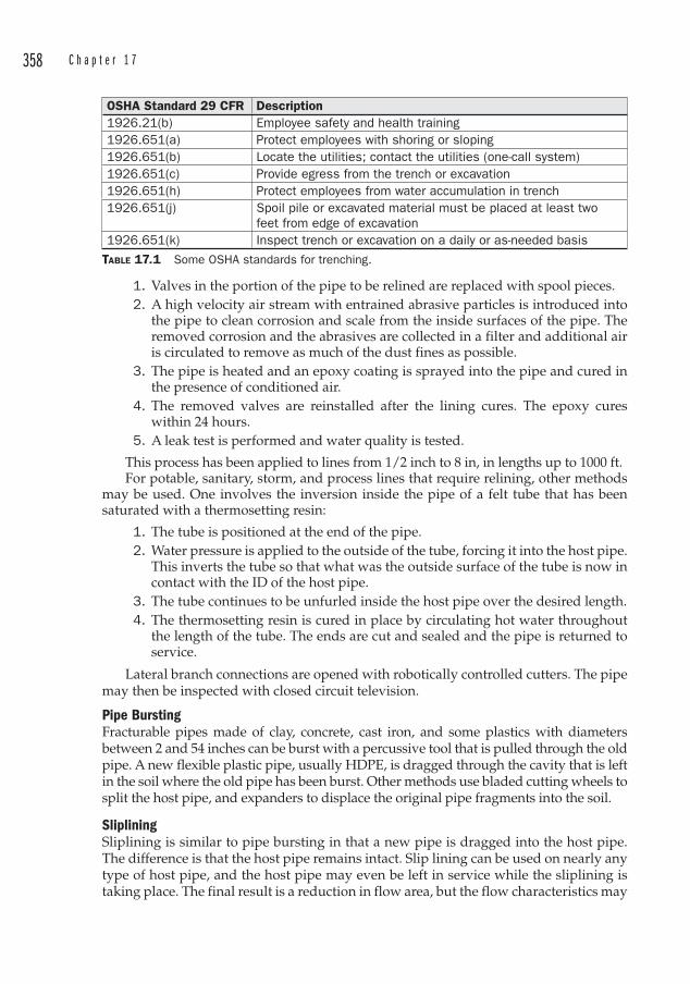
358 C h a p t e r 1 7
1. Valves in the portion of the pipe to be relined are replaced with spool pieces. 2. A high velocity air stream with entrained abrasive particles is introduced into
the pipe to clean corrosion and scale from the inside surfaces of the pipe. The removed corrosion and the abrasives are collected in a filter and additional air is circulated to remove as much of the dust fines as possible.
3. The pipe is heated and an epoxy coating is sprayed into the pipe and cured in the presence of conditioned air.
4. The removed valves are reinstalled after the lining cures. The epoxy cures within 24 hours.
5. A leak test is performed and water quality is tested.
This process has been applied to lines from 1/2 inch to 8 in, in lengths up to 1000 ft.For potable, sanitary, storm, and process lines that require relining, other methods
may be used. One involves the inversion inside the pipe of a felt tube that has been saturated with a thermosetting resin:
1. The tube is positioned at the end of the pipe. 2. Water pressure is applied to the outside of the tube, forcing it into the host pipe.
This inverts the tube so that what was the outside surface of the tube is now in contact with the ID of the host pipe.
3. The tube continues to be unfurled inside the host pipe over the desired length. 4. The thermosetting resin is cured in place by circulating hot water throughout
the length of the tube. The ends are cut and sealed and the pipe is returned to service.
Lateral branch connections are opened with robotically controlled cutters. The pipe may then be inspected with closed circuit television.
Pipe Bursting Fracturable pipes made of clay, concrete, cast iron, and some plastics with diameters between 2 and 54 inches can be burst with a percussive tool that is pulled through the old pipe. A new flexible plastic pipe, usually HDPE, is dragged through the cavity that is left in the soil where the old pipe has been burst. Other methods use bladed cutting wheels to split the host pipe, and expanders to displace the original pipe fragments into the soil.
SlipliningSliplining is similar to pipe bursting in that a new pipe is dragged into the host pipe. The difference is that the host pipe remains intact. Slip lining can be used on nearly any type of host pipe, and the host pipe may even be left in service while the sliplining is taking place. The final result is a reduction in flow area, but the flow characteristics may
OSHA Standard 29 CFR Description1926.21(b) Employee safety and health training1926.651(a) Protect employees with shoring or sloping1926.651(b) Locate the utilities; contact the utilities (one-call system)1926.651(c) Provide egress from the trench or excavation1926.651(h) Protect employees from water accumulation in trench1926.651(j) Spoil pile or excavated material must be placed at least two
feet from edge of excavation1926.651(k) Inspect trench or excavation on a daily or as-needed basis
TABLE 17.1 Some OSHA standards for trenching.
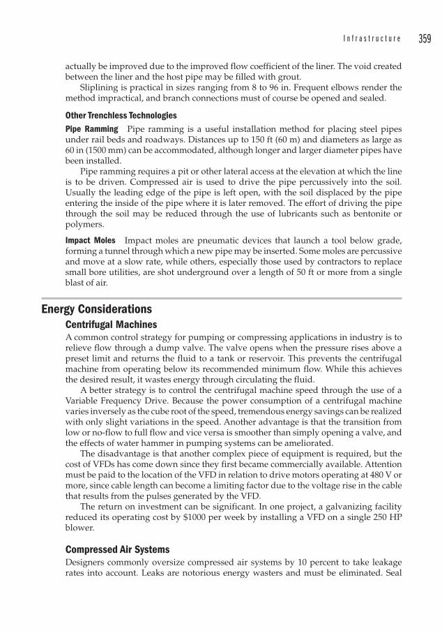
I n f r a s t r u c t u r e 359
actually be improved due to the improved flow coefficient of the liner. The void created between the liner and the host pipe may be filled with grout.
Sliplining is practical in sizes ranging from 8 to 96 in. Frequent elbows render the method impractical, and branch connections must of course be opened and sealed.
Other Trenchless TechnologiesPipe Ramming Pipe ramming is a useful installation method for placing steel pipes under rail beds and roadways. Distances up to 150 ft (60 m) and diameters as large as 60 in (1500 mm) can be accommodated, although longer and larger diameter pipes have been installed.
Pipe ramming requires a pit or other lateral access at the elevation at which the line is to be driven. Compressed air is used to drive the pipe percussively into the soil. Usually the leading edge of the pipe is left open, with the soil displaced by the pipe entering the inside of the pipe where it is later removed. The effort of driving the pipe through the soil may be reduced through the use of lubricants such as bentonite or polymers.
Impact Moles Impact moles are pneumatic devices that launch a tool below grade, forming a tunnel through which a new pipe may be inserted. Some moles are percussive and move at a slow rate, while others, especially those used by contractors to replace small bore utilities, are shot underground over a length of 50 ft or more from a single blast of air.
Energy Considerations Centrifugal MachinesA common control strategy for pumping or compressing applications in industry is to relieve flow through a dump valve. The valve opens when the pressure rises above a preset limit and returns the fluid to a tank or reservoir. This prevents the centrifugal machine from operating below its recommended minimum flow. While this achieves the desired result, it wastes energy through circulating the fluid.
A better strategy is to control the centrifugal machine speed through the use of a Variable Frequency Drive. Because the power consumption of a centrifugal machine varies inversely as the cube root of the speed, tremendous energy savings can be realized with only slight variations in the speed. Another advantage is that the transition from low or no-flow to full flow and vice versa is smoother than simply opening a valve, and the effects of water hammer in pumping systems can be ameliorated.
The disadvantage is that another complex piece of equipment is required, but the cost of VFDs has come down since they first became commercially available. Attention must be paid to the location of the VFD in relation to drive motors operating at 480 V or more, since cable length can become a limiting factor due to the voltage rise in the cable that results from the pulses generated by the VFD.
The return on investment can be significant. In one project, a galvanizing facility reduced its operating cost by $1000 per week by installing a VFD on a single 250 HP blower.
Compressed Air SystemsDesigners commonly oversize compressed air systems by 10 percent to take leakage rates into account. Leaks are notorious energy wasters and must be eliminated. Seal
360 C h a p t e r 1 7
welding threaded joints is a good practice, but so is the intelligent routing of air lines through accessible areas where they may be maintained. Lines routed underground or through trenches will never receive adequate maintenance.
The Association of Energy Engineers estimates that the energy lost through a hole that is 1/16 in diameter is 5800 kWh/year in a system th at operates at 100 psi. At a modest cost of $0.03/kWh, this equates to $174 per year. Refer to Figure 17.1 for losses at other conditions.
Water Conservation Water shortages occur throughout the world due to lack of precipitation, overconsumption, misuse of resources, and pollution of fresh water reserves. In the United States, the traditional dry region was the southwest, which is fed by the relatively small Colorado River . In recent years, other areas of the country have suffered the effects of low water reservoirs. The phenomenon of urban sprawl throughout the Sunbelt has stretched the ability of the existing infrastructure to meet the demands of modern life in a developed country. Water restrictions are often implemented as a stop-gap measure of dealing with a diminished supply of fresh water.
Prior to a series of federal laws that were enacted to protect water resources, industries would routinely dump waste water into rivers and streams. Such pollution led to fires on the Cuyahoga River as early as 1936. The 1969 Cuyhoga River fire helped to spawn the Clean Water Act of 1977 , which required industries to limit the amount of effluent discharged into bodies of water.
Waste water treatment is an expensive proposition, and industries realized that it was cheaper to conserve water than to treat it. As a result water efficiency in industry as a whole improved. While low-flow toilets and shower heads decrease water consumption on the household level, the greater effects on water consumption and surface water quality are realized on the industrial level.
Other opportunities exist for water conservation, and engineers designing new utility systems look to material less prone to leakage, while water utilities work to rehabilitate aging infrastructure that used leadite sealed joints on cast iron lines.
FIGURE 17.1 Energy lost due to leaks in a compressed air system. Printed with permission “Handbook of Energy Management,” published by Fairmont Press.
361
CHAPTER 18Strategies for Remote Locations
During a visit to Saint Vincent College a few years ago, I ran into one of my calculus professors who I knew was involved in charity work in Haiti. He invited me into his office and I asked about his work there. Out came an engineering report that was prepared by a team of Cuban engineers to address a water distribution problem. The good professor optimistically said “Maybe you’d like to look at this.” Then upon reflection, he lowered it and said cautiously, “But this is probably more civil engineering than mechanical.”
I explained that I had lots of experience moving lots of water in lots of places, and I would be happy to review the report. The report was remarkable for the level of detail it contained. The conclusions were very good, but I did take exception to some of the recommendations.
First, they wanted to use a diesel motor to run an electric generator, to run an electric pump. This would occur near a water source, and my concern was that diesel spills would contaminate the source, the cost of fuel would get expensive, and there would in general be quite a lot of pollution. I decided to investigate solar powered pumps .
Second, they wanted to bury galvanized threaded pipe to route the piping from the source in the valley up to the top of a mountain where the road crested at a restaurant. While I knew that the galvanized pipe would assemble rapidly, I also knew that it would restrict flow, eventually corrode, and would likely contain trace lead from the galvanizing process. I suggested HDPE , with fewer fittings and field-applied fusion sleeves. The cost would also be low, it would still be easy to assemble, and the HDPE would last indefinitely.
Third, I also noticed that the lengths and elevations had been estimated by the Cubans. We would need accurate elevations and distances to size the equipment. It turned out that my brother had a hand-held GPS unit that provided elevation, so a few months after I submitted my review of the original report, my professor and I, along with my brother (who yearns for excitement), left with a small group of people bound for Port au Prince, and other parts unknown.
The result was a week of camaraderie, sight-seeing, minor repairs to the hostel in which we stayed, miserable digestive issues, errant late-night gunfire that was far too close for comfort, and the appreciation of having clean, potable water at the tap when you want it back home. We also performed the survey and I designed the system.
It was not installed as designed however. The Owner decided to purchase a diesel generator instead--which proves that you can lead a client to water, but you cannot make him use the best technology.
362 C h a p t e r 1 8
Remote or undeveloped regions do not contain the infrastructure to conveniently deliver potable water. Water may still be delivered in such regions from suitable sources such as springs or wells, however, alternate technologies are often required to provide the motive force for pumping applications.
Such motive force may derive its energy from carbon-based fuels and engines, solar power, kinetic energy, or even manpower. The quantities of water to be moved are generally small in such cases, and this is fortunate, since large volumes require large power sources1. The pressure required is often high though, and this requires low-flow, high-head pumps, which forces the design toward positive displacement pumps.
HDPE is a good choice for long runs of underground piping if it can be delivered to the site. HDPE is impervious to corrosion, has a low friction factor, and can be purchased in long lengths on spools. This minimizes the number of field joints, and these can be made using thermofusion sleeves that are normally used for repairs.
Field surveys can be made with hand-held GPS devices, which can provide data for elevation above sea level as well as northing and easting coordinates. This forms the basis of pressure drop calculations used to size the pumps and determine power requirements.
Motive Power TechnologiesSolar PowerUse of solar panels is limited to areas that receive lots of sunshine for many hours. In the continental United States, the combined solar incidence and current panel efficiencies yield a power density of approximately 0.015 HP/ft2 (120 W/m2), so the application of solar panels is further limited to relatively low power requirements. Still, they are an economical and environmentally sound choice for many remote projects. See Figure 18.1.
Hydraulic Ram Pump The hydraulic ram pump, also known as a Bélier hydraulic pump, was invented in 1796 by Joseph Michel Montgolfier 2. The design and construction are simple, although their practical use is limited to remote areas that lack electricity. They also require a significant change in elevation of the water source.
The hydraulic ram pump consists of a pressure chamber filled with air and a spring or weight loaded check valve known as a “waste” or “clack ” valve from the sound it makes during operation. A delivery check valve keeps the pumped water column from falling back through the device.
A source of water at a higher elevation is required, as at a waterfall or pond. The waste valve is initially open and as the water falls from a higher elevation, the kinetic energy forces the weighted waste valve closed. This causes a water hammer that forces some of the falling water through the delivery check valve and out of the pump to its point of use. The pressure chamber acts as a shock absorber. See Figure 18.2.
The hydraulic ram pump acts essentially as a positive displacement pump, with spurts of water delivered in cycles rather than a continuous flow. Experiments by the University of Warwick indicate that the pressure chamber should have a minimum 1 Some clever sources of man-made power include merry-go-rounds and see-saws. As children play in a park, they are actually pumping water to a storage tank. This technology has been successfully applied in Gaviotas, Colombia . 2 Of the flying Montgolfier brothers, inventors of the hot air balloon.
S t r a t e g i e s f o r R e m o t e L o c a t i o n s 363
volume of 20 times the expected flow rate per cycle, with the flow per cycle depending on the diameter of the inlet pipe. The pressure chamber should include a bladder or else the entrapped air will dissolve into the water. An expansion tank may be used, but in remote applications, a partially inflated bicycle tire jammed into the tank (which is really nothing more than a larger diameter pipe) may be used.
The inlet pipe should be rigid, although good results have been reported with PVC pipe. This inlet pipe from the source to the pump is also known as a drive pipe, and the optimum length to diameter ratio appears to be between 150 and 100, based on studies performed by N. G. Calvert. The delivery of the pump depends on the fall from the source, the flow available from the source, and the height of the delivery point above the pump. A common equation for use in estimating the delivery is:
0.6 � Q � F/E � D (Equation 18.1)
where
Q � Source flow in gallons per minute
F � Fall in feet from the water source to the pump
E � Elevation from the pump to the water outlet
D � Capacity of the pump in gallons per minute.
The 0.6 is an efficiency factor and will differ among various ram pumps. Note that much water is “wasted” through the waste check valve, in the sense that it is not pumped. It often returns to the natural stream from which it came though, so in that sense the water is conserved.
Water TreatmentOnce the water is delivered to a tank or cistern, some minimal degree of water treatment should be considered. These will be customized to the area. For example, Guinea Worm Disease may be avoided simply through water filtration. This disease, once prevalent throughout Africa and Asia, remains endemic only in five countries in sub-Saharan Africa.
Water-borne diseases are caused by:
• Protozoa
• Bacteria
• Viruses
• Parasites.
BoilingBoiling is considered to be the best method of treating water to make it potable, but this is considered to be a “point-of-use” treatment, and would not be appropriate to a remote piping system. Some pathogens that cause botulism can survive at temperatures up to 244°F (118°C) so boiling at pressures higher than atmospheric would be required.
Filtration Bacteria , parasites, and protozoa can be filtered successfully, but viruses are too small to be filtered. This requires chemical additives or ultraviolet disinfection after filtration. Chemicals may include chlorine, iodine , chlorine dioxide , or sodium hypochlorite

364 C h a p t e r 1 8
(bleach). Care must be taken with filters to prevent the filter media from becoming a colonization site for the microbes. Bonding silver particles to the media decreases the growth of these microbes in the filters. This is due to the germicidal properties of many metals.
Chemical Disinfection Iodine kills many pathogens, and is available in liquid or solid form. Ascorbic acid is frequently added to water treated with iodine to help remove the iodine taste. Chlorine bleach can also be used as a disinfectant. Two drops of 5% sodium hypochlorite is added per quart (liter) of water and left covered for an hour. While iodine and chlorine are each effective against Giardia, neither is sufficient to kill Cryptosporidia .
Silver ion/chlorine dioxide is effective against Cryptosporidia and Giardia, but the disinfection time is up to four hours.
PRESSURE GAUGE ASSEMBLY
OR
OR
22
22
6 7
16 21SPRING NO. 2N 18º 22.152�E 72º 35.228�2.5 GPM � 150 GPH � 3500 GPD
HOLD FOR SIZE OF DISCHARGE PIPE
COPPER
HDPE
1
2
3
4
5101
28 18
107
106
103 104 105
10 16
COPPER
HDPE
1 1/4�
201102
12
14
11
17
1513
19
202224
8 23
3
CISTERNN 18º 22.273�E 72º 35.282�ELEV 2580 FT ASLCAPACITY � 4000 GALLON
FIGURE 18.1 A remote solar-powered water pumping project for a village in Haiti. Courtesy of Innovative Design Engineering of America, LLC.
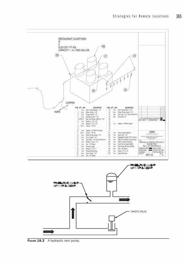
S t r a t e g i e s f o r R e m o t e L o c a t i o n s 365
ITEM QTY UNIT DESCRIPTIONITEM QTY UNIT DESCRIPTION1 1 ea Valve, 3-Way Manual, 1 1/2"2 5 ea Elbow, 90 deg, 1 1/2"3 2 ea Flange, Sweat, 1 1/2"4 2 ea Mechanical Joint, 1 1/2"5 2700 LF Pipe, 5100 Series, SDR 9.0, 1 1/2"6 1 ea Bushing, 1 1/4" x 1/2"7 1 ea Bushing, 1 1/2" x 1/2"8 30 LF Tubing, 1 1/2" OD9
10 1 ea Adapter, 1 1/4" NPTF to Sweat11 20 LF Tubing, 1 1/4" OD12 2 ea Elbow, 90 deg, Sweat, 1 1/4" 13 2 ea Union, Sweat, 1 1/4"14 1 ea Valve, Ball, 1 1/4" Full Port NSF-61-815 1 ea Strainer, Y-Type, 1 1/4"16 1 ea Tee, 1 1/4" Sweat17 2 ea Pressure Gauge, 18 1 ea Reducer, 1 1/2" x 1"19 1 ea Pressure Relief Valve20 2 ea Union, Sweat, 1 1/2"21 3 ea Tee, 1 1/2" Sweat
22 1 ea Valve, Swing Check, 1 1/2"23 6 ea Elbow, 90 deg, Sweat, 1 1/2"24 3 ea Valve, Ball, 1 1/2" Full Port NSF-61-825 8 ea Valve, Ball, 1/2"262728 1 ea Adapter, 1" NPTM to Sweat293031
101 1 ea Pump, Solaram 8243-24102 1 ea Valve, Foot, 1 1/4"103 1 ea Adaptable Controller, PPT 12/24-30104 1 ea PSPV PV Combiner (Junction Box)105 7 ea OBPV-10 Series Protection106 1 ea Fixed Pole Top Rack 500465107 7 ea Solar Panel, BP Solar SX160B108 4 ea Tank, 1000 Gallon, 201 1 ea Cistern, 10' x 6' x 9'202 1 ea Support Structure
21202
108
26
24
25
COPPER
HDPE
RESTAURANT COURTYARDNEELEV 2811 FT ASLCAPACITY � 4 x 1000 GALLON
A 8/14/2008 ISSUED FOR REVIEWREV. DATE DESCRIPTION
Innovative Design Engineering of America, LLCPittsburgh, Pennsylvania
412.242.4347
MACALLA WATER PROJECTISOMETRIC
BILL OF MATERIALS
TITLE:
ENGINEER: BKSDRAWN: BKSCHECKED:DRAWING
8001-03REV.
A
SCALE: NONEPROJECT NO: 8001PAD FILE. 8001-03
WASTE VALVE
FIGURE 18.2 A hydraulic ram pump.

366 C h a p t e r 1 8
Ultraviolet Radiation Ultraviolet radiation destroys DNA and this prevents microbes from reproducing. While this technology may seem inappropriate to remote locations, it is feasible to apply it as a batch method of treatment using a technique known as “solar disinfection. ” Water is shaken in a transparent bottle to oxygenate it, and is left in full sunlight for six hours. This raises the temperature of the water and exposes the microbes to UVA radiation.
367
Appendices
Appendix 1—Carbon Steel Pipe Schedule
Appeddix 2—PVC Pipe Schedule
Appendix 3—Copper Tubing Schedule
Appendix 4—Material Properties
Appendix 5—NEMA Enclosures
Appendix 6—IP Codes
Appendix 7—Steam Tables (English Units)
Appendix 8—Steam Tables (SI Units)
Appendix 9—Friction Losses
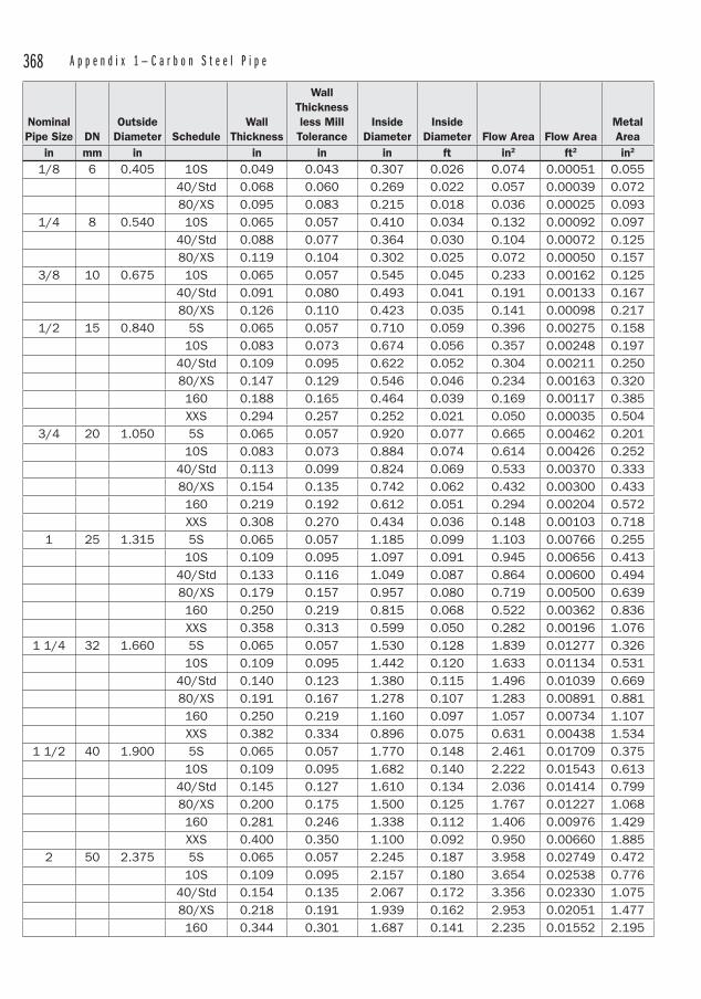
368 A p p e n d i x 1 — C a r b o n S t e e l P i p e
NominalPipe Size DN
OutsideDiameter Schedule
Wall Thickness
Wall Thicknessless Mill Tolerance
InsideDiameter
InsideDiameter Flow Area Flow Area
MetalArea
in mm in in in in ft in2 ft2 in2
1/8 6 0.405 10S 0.049 0.043 0.307 0.026 0.074 0.00051 0.055 40/Std 0.068 0.060 0.269 0.022 0.057 0.00039 0.072 80/XS 0.095 0.083 0.215 0.018 0.036 0.00025 0.093
1/4 8 0.540 10S 0.065 0.057 0.410 0.034 0.132 0.00092 0.097 40/Std 0.088 0.077 0.364 0.030 0.104 0.00072 0.125 80/XS 0.119 0.104 0.302 0.025 0.072 0.00050 0.157
3/8 10 0.675 10S 0.065 0.057 0.545 0.045 0.233 0.00162 0.125 40/Std 0.091 0.080 0.493 0.041 0.191 0.00133 0.167 80/XS 0.126 0.110 0.423 0.035 0.141 0.00098 0.217
1/2 15 0.840 5S 0.065 0.057 0.710 0.059 0.396 0.00275 0.158 10S 0.083 0.073 0.674 0.056 0.357 0.00248 0.197 40/Std 0.109 0.095 0.622 0.052 0.304 0.00211 0.250 80/XS 0.147 0.129 0.546 0.046 0.234 0.00163 0.320 160 0.188 0.165 0.464 0.039 0.169 0.00117 0.385 XXS 0.294 0.257 0.252 0.021 0.050 0.00035 0.504
3/4 20 1.050 5S 0.065 0.057 0.920 0.077 0.665 0.00462 0.201 10S 0.083 0.073 0.884 0.074 0.614 0.00426 0.252 40/Std 0.113 0.099 0.824 0.069 0.533 0.00370 0.333 80/XS 0.154 0.135 0.742 0.062 0.432 0.00300 0.433 160 0.219 0.192 0.612 0.051 0.294 0.00204 0.572 XXS 0.308 0.270 0.434 0.036 0.148 0.00103 0.7181 25 1.315 5S 0.065 0.057 1.185 0.099 1.103 0.00766 0.255 10S 0.109 0.095 1.097 0.091 0.945 0.00656 0.413 40/Std 0.133 0.116 1.049 0.087 0.864 0.00600 0.494 80/XS 0.179 0.157 0.957 0.080 0.719 0.00500 0.639 160 0.250 0.219 0.815 0.068 0.522 0.00362 0.836 XXS 0.358 0.313 0.599 0.050 0.282 0.00196 1.076
1 1/4 32 1.660 5S 0.065 0.057 1.530 0.128 1.839 0.01277 0.326 10S 0.109 0.095 1.442 0.120 1.633 0.01134 0.531 40/Std 0.140 0.123 1.380 0.115 1.496 0.01039 0.669 80/XS 0.191 0.167 1.278 0.107 1.283 0.00891 0.881 160 0.250 0.219 1.160 0.097 1.057 0.00734 1.107 XXS 0.382 0.334 0.896 0.075 0.631 0.00438 1.534
1 1/2 40 1.900 5S 0.065 0.057 1.770 0.148 2.461 0.01709 0.375 10S 0.109 0.095 1.682 0.140 2.222 0.01543 0.613 40/Std 0.145 0.127 1.610 0.134 2.036 0.01414 0.799 80/XS 0.200 0.175 1.500 0.125 1.767 0.01227 1.068 160 0.281 0.246 1.338 0.112 1.406 0.00976 1.429 XXS 0.400 0.350 1.100 0.092 0.950 0.00660 1.8852 50 2.375 5S 0.065 0.057 2.245 0.187 3.958 0.02749 0.472 10S 0.109 0.095 2.157 0.180 3.654 0.02538 0.776 40/Std 0.154 0.135 2.067 0.172 3.356 0.02330 1.075 80/XS 0.218 0.191 1.939 0.162 2.953 0.02051 1.477 160 0.344 0.301 1.687 0.141 2.235 0.01552 2.195
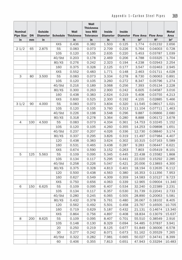
A p p e n d i x 1 — C a r b o n S t e e l P i p e s 369
NominalPipe Size DN
OutsideDiameter Schedule
Wall Thickness
Wall Thicknessless Mill Tolerance
InsideDiameter
InsideDiameter Flow Area Flow Area
MetalArea
in mm in in in in ft in2 ft2 in2
XXS 0.436 0.382 1.503 0.125 1.774 0.01232 2.6562 1/2 65 2.875 5S 0.083 0.073 2.709 0.226 5.764 0.04003 0.728
10S 0.120 0.105 2.635 0.220 5.453 0.03787 1.039 40/Std 0.203 0.178 2.469 0.206 4.788 0.03325 1.704 80/XS 0.276 0.242 2.323 0.194 4.238 0.02943 2.254 160 0.375 0.328 2.125 0.177 3.547 0.02463 2.945 XXS 0.552 0.483 1.771 0.148 2.463 0.01711 4.0283 80 3.500 5S 0.083 0.073 3.334 0.278 8.730 0.06063 0.891 10S 0.120 0.105 3.260 0.272 8.347 0.05796 1.274 40/Std 0.216 0.189 3.068 0.256 7.393 0.05134 2.228 80/XS 0.300 0.263 2.900 0.242 6.605 0.04587 3.016 160 0.438 0.383 2.624 0.219 5.408 0.03755 4.213 XXS 0.600 0.525 2.300 0.192 4.155 0.02885 5.466
3 1/2 90 4.000 5S 0.083 0.073 3.834 0.320 11.545 0.08017 1.021 10S 0.120 0.105 3.760 0.313 11.104 0.07711 1.463 40/Std 0.226 0.198 3.548 0.296 9.887 0.06866 2.680 80/XS 0.318 0.278 3.364 0.280 8.888 0.06172 3.6784 100 4.500 5S 0.083 0.073 4.334 0.361 14.753 0.10245 1.152 10S 0.120 0.105 4.260 0.355 14.253 0.09898 1.651 40/Std 0.237 0.207 4.026 0.336 12.730 0.08840 3.174 80/XS 0.337 0.295 3.826 0.319 11.497 0.07984 4.407 120 0.438 0.383 3.624 0.302 10.315 0.07163 5.589 160 0.531 0.465 3.438 0.287 9.283 0.06447 6.621 XXS 0.674 0.590 3.152 0.263 7.803 0.05419 8.1015 125 5.563 5S 0.109 0.095 5.345 0.445 22.438 0.15582 1.868 10S 0.134 0.117 5.295 0.441 22.020 0.15292 2.285 40/Std 0.258 0.226 5.047 0.421 20.006 0.13893 4.300 80/XS 0.375 0.328 4.813 0.401 18.194 0.12635 6.112 120 0.500 0.438 4.563 0.380 16.353 0.11356 7.953 160 0.627 0.549 4.309 0.359 14.583 0.10127 9.723 XXS 0.750 0.656 4.063 0.339 12.965 0.09004 11.3406 150 6.625 5S 0.109 0.095 6.407 0.534 32.240 0.22389 2.231 10S 0.134 0.117 6.357 0.530 31.739 0.22041 2.733 40/Std 0.280 0.245 6.065 0.505 28.890 0.20063 5.581 80/XS 0.432 0.378 5.761 0.480 26.067 0.18102 8.405 120 0.562 0.492 5.501 0.458 23.767 0.16505 10.705 160 0.719 0.629 5.187 0.432 21.131 0.14674 13.340 XXS 0.864 0.756 4.897 0.408 18.834 0.13079 15.6378 200 8.625 5S 0.109 0.095 8.407 0.701 55.510 0.38549 2.916 10S 0.148 0.130 8.329 0.694 54.485 0.37837 3.941 20 0.250 0.219 8.125 0.677 51.849 0.36006 6.578 30 0.277 0.242 8.071 0.673 51.162 0.35529 7.265 40/Std 0.322 0.282 7.981 0.665 50.027 0.34741 8.399 60 0.406 0.355 7.813 0.651 47.943 0.33294 10.483

370 A p p e n d i x 1 — C a r b o n S t e e l P i p e
NominalPipe Size DN
OutsideDiameter Schedule
Wall Thickness
Wall Thicknessless Mill Tolerance
InsideDiameter
InsideDiameter Flow Area Flow Area
MetalArea
in mm in in in in ft in2 ft2 in2
80/XS 0.500 0.438 7.625 0.635 45.664 0.31711 12.763 100 0.594 0.520 7.437 0.620 43.440 0.30166 14.987 120 0.719 0.629 7.187 0.599 40.568 0.28172 17.858 140 0.812 0.711 7.001 0.583 38.495 0.26733 19.931
XXS 0.875 0.766 6.875 0.573 37.122 0.25779 21.304 160 0.906 0.793 6.813 0.568 36.456 0.25317 21.97010 250 10.750 5S 0.134 0.117 10.482 0.874 86.293 0.59926 4.469 10S 0.165 0.144 10.420 0.868 85.276 0.59219 5.487 20 0.250 0.219 10.250 0.854 82.516 0.57303 8.247 30 0.307 0.269 10.136 0.845 80.691 0.56035 10.072 40 0.365 0.319 10.020 0.835 78.854 0.54760 11.908 Std 0.365 0.319 10.020 0.835 78.854 0.54760 11.908 60/XS 0.500 0.438 9.750 0.813 74.662 0.51849 16.101 80 0.594 0.520 9.562 0.797 71.810 0.49868 18.952 100 0.719 0.629 9.312 0.776 68.104 0.47295 22.658 120 0.844 0.739 9.062 0.755 64.497 0.44789 26.266 140/XXS 1.000 0.875 8.750 0.729 60.132 0.41758 30.631 160 1.125 0.984 8.500 0.708 56.745 0.39406 34.01812 300 12.750 5S 0.156 0.137 12.438 1.037 121.504 0.84378 6.172 10S 0.180 0.158 12.390 1.033 120.568 0.83728 7.108 20 0.250 0.219 12.250 1.021 117.859 0.81846 9.817 30 0.330 0.289 12.090 1.008 114.800 0.79722 12.876 Std 0.375 0.328 12.000 1.000 113.097 0.78540 14.579 40 0.406 0.355 11.938 0.995 111.932 0.77730 15.745
XS 0.500 0.438 11.750 0.979 108.434 0.75301 19.242 60 0.562 0.492 11.626 0.969 106.157 0.73720 21.519 80 0.688 0.602 11.374 0.948 101.605 0.70559 26.071 100 0.844 0.739 11.062 0.922 96.107 0.66741 31.569 120/XXS 1.000 0.875 10.750 0.896 90.762 0.63030 36.914 140 1.125 0.984 10.500 0.875 86.590 0.60132 41.086 160 1.312 1.148 10.126 0.844 80.531 0.55925 47.14514 350 14.000 5S 0.156 0.137 13.688 1.141 147.153 1.02190 6.785 10S 0.250 0.219 13.500 1.125 143.139 0.99402 10.799 20 0.312 0.273 13.376 1.115 140.521 0.97584 13.417 30/Std 0.375 0.328 13.250 1.104 137.886 0.95754 16.052 40 0.438 0.383 13.124 1.094 135.276 0.93942 18.662 XS 0.500 0.438 13.000 1.083 132.732 0.92175 21.206 60 0.594 0.520 12.812 1.068 128.921 0.89528 25.017 80 0.750 0.656 12.500 1.042 122.718 0.85221 31.220 100 0.938 0.821 12.124 1.010 115.447 0.80171 38.491 120 1.094 0.957 11.812 0.984 109.581 0.76098 44.357 140 1.250 1.094 11.500 0.958 103.869 0.72131 50.069 160 1.406 1.230 11.188 0.932 98.309 0.68270 55.62916 400 16.000 5S 0.165 0.144 15.670 1.306 192.853 1.33926 8.208
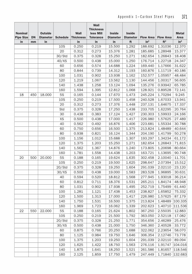
A p p e n d i x 1 — C a r b o n S t e e l P i p e s 371
NominalPipe Size DN
OutsideDiameter Schedule
Wall Thickness
Wall Thicknessless Mill Tolerance
InsideDiameter
InsideDiameter Flow Area Flow Area
MetalArea
in mm in in in in ft in2 ft2 in2
10S 0.250 0.219 15.500 1.292 188.692 1.31036 12.370 20 0.312 0.273 15.376 1.281 185.685 1.28948 15.377 30/Std 0.375 0.328 15.250 1.271 182.654 1.26843 18.408 40/XS 0.500 0.438 15.000 1.250 176.714 1.22718 24.347 60 0.656 0.574 14.688 1.224 169.440 1.17666 31.622 80 0.844 0.739 14.312 1.193 160.876 1.11719 40.186 100 1.031 0.902 13.938 1.162 152.577 1.05957 48.484 120 1.219 1.067 13.562 1.130 144.456 1.00317 56.605 140 1.438 1.258 13.124 1.094 135.276 0.93942 65.785 160 1.594 1.395 12.812 1.068 128.921 0.89528 72.141
18 450 18.000 5S 0.165 0.144 17.670 1.473 245.224 1.70294 9.245 10S 0.250 0.219 17.500 1.458 240.528 1.67033 13.941 20 0.312 0.273 17.376 1.448 237.131 1.64675 17.337 Std 0.375 0.328 17.250 1.438 233.705 1.62295 20.764 30 0.438 0.383 17.124 1.427 230.303 1.59933 24.166 XS 0.500 0.438 17.000 1.417 226.980 1.57625 27.489 40 0.562 0.492 16.876 1.406 223.681 1.55334 30.788 60 0.750 0.656 16.500 1.375 213.824 1.48489 40.644 80 0.938 0.821 16.124 1.344 204.190 1.41799 50.278 100 1.156 1.012 15.688 1.307 193.297 1.34234 61.172 120 1.375 1.203 15.250 1.271 182.654 1.26843 71.815 140 1.562 1.367 14.876 1.240 173.805 1.20698 80.664 160 1.781 1.558 14.438 1.203 163.721 1.13695 90.748
20 500 20.000 5S 0.188 0.165 19.624 1.635 302.458 2.10040 11.701 10S 0.250 0.219 19.500 1.625 298.647 2.07394 15.512 20/Std 0.375 0.328 19.250 1.604 291.039 2.02110 23.120 30/XS 0.500 0.438 19.000 1.583 283.528 1.96895 30.631 40 0.594 0.520 18.812 1.568 277.945 1.93018 36.214 60 0.812 0.711 18.376 1.531 265.211 1.84174 48.948 80 1.031 0.902 17.938 1.495 252.719 1.75499 61.440 100 1.281 1.121 17.438 1.453 238.827 1.65852 75.332 120 1.500 1.313 17.000 1.417 226.980 1.57625 87.179 140 1.750 1.531 16.500 1.375 213.824 1.48489 100.335 160 1.969 1.723 16.062 1.339 202.623 1.40710 111.536
22 550 22.000 5S 0.188 0.165 21.624 1.802 367.250 2.55035 12.883 10S 0.250 0.219 21.500 1.792 363.050 2.52118 17.082 20/Std 0.375 0.328 21.250 1.771 354.656 2.46289 25.476 30/XS 0.500 0.438 21.000 1.750 346.360 2.40528 33.772 60 0.875 0.766 20.250 1.688 322.062 2.23654 58.070 80 1.125 0.984 19.750 1.646 306.354 2.12746 73.778 100 1.375 1.203 19.250 1.604 291.039 2.02110 89.094 120 1.625 1.422 18.750 1.563 276.116 1.91747 104.016 140 1.875 1.641 18.250 1.521 261.586 1.81657 118.546 160 2.125 1.859 17.750 1.479 247.449 1.71840 132.683
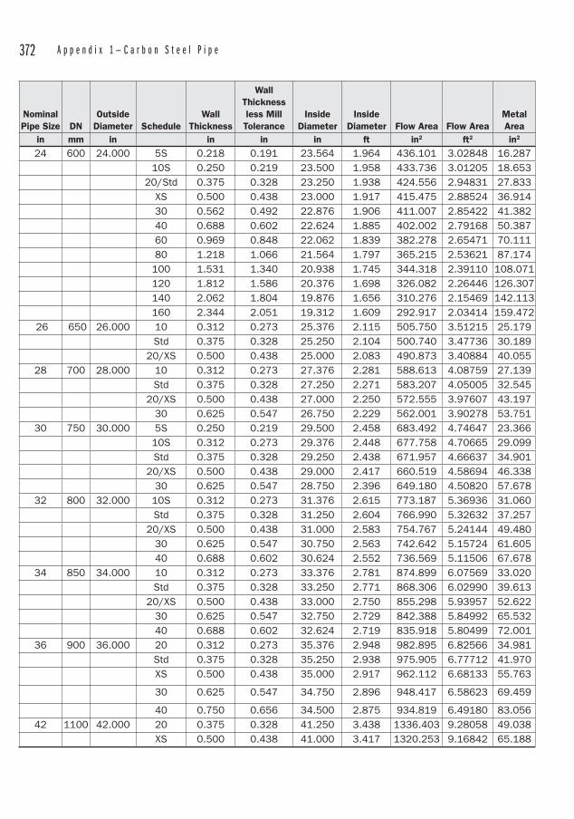
372 A p p e n d i x 1 — C a r b o n S t e e l P i p e
NominalPipe Size DN
OutsideDiameter Schedule
Wall Thickness
Wall Thicknessless Mill Tolerance
InsideDiameter
InsideDiameter Flow Area Flow Area
MetalArea
in mm in in in in ft in2 ft2 in2
24 600 24.000 5S 0.218 0.191 23.564 1.964 436.101 3.02848 16.287 10S 0.250 0.219 23.500 1.958 433.736 3.01205 18.653 20/Std 0.375 0.328 23.250 1.938 424.556 2.94831 27.833 XS 0.500 0.438 23.000 1.917 415.475 2.88524 36.914 30 0.562 0.492 22.876 1.906 411.007 2.85422 41.382 40 0.688 0.602 22.624 1.885 402.002 2.79168 50.387 60 0.969 0.848 22.062 1.839 382.278 2.65471 70.111 80 1.218 1.066 21.564 1.797 365.215 2.53621 87.174 100 1.531 1.340 20.938 1.745 344.318 2.39110 108.071 120 1.812 1.586 20.376 1.698 326.082 2.26446 126.307 140 2.062 1.804 19.876 1.656 310.276 2.15469 142.113 160 2.344 2.051 19.312 1.609 292.917 2.03414 159.472
26 650 26.000 10 0.312 0.273 25.376 2.115 505.750 3.51215 25.179 Std 0.375 0.328 25.250 2.104 500.740 3.47736 30.189 20/XS 0.500 0.438 25.000 2.083 490.873 3.40884 40.05528 700 28.000 10 0.312 0.273 27.376 2.281 588.613 4.08759 27.139 Std 0.375 0.328 27.250 2.271 583.207 4.05005 32.545 20/XS 0.500 0.438 27.000 2.250 572.555 3.97607 43.197 30 0.625 0.547 26.750 2.229 562.001 3.90278 53.75130 750 30.000 5S 0.250 0.219 29.500 2.458 683.492 4.74647 23.366 10S 0.312 0.273 29.376 2.448 677.758 4.70665 29.099 Std 0.375 0.328 29.250 2.438 671.957 4.66637 34.901 20/XS 0.500 0.438 29.000 2.417 660.519 4.58694 46.338 30 0.625 0.547 28.750 2.396 649.180 4.50820 57.67832 800 32.000 10S 0.312 0.273 31.376 2.615 773.187 5.36936 31.060 Std 0.375 0.328 31.250 2.604 766.990 5.32632 37.257 20/XS 0.500 0.438 31.000 2.583 754.767 5.24144 49.480 30 0.625 0.547 30.750 2.563 742.642 5.15724 61.605 40 0.688 0.602 30.624 2.552 736.569 5.11506 67.67834 850 34.000 10 0.312 0.273 33.376 2.781 874.899 6.07569 33.020 Std 0.375 0.328 33.250 2.771 868.306 6.02990 39.613 20/XS 0.500 0.438 33.000 2.750 855.298 5.93957 52.622 30 0.625 0.547 32.750 2.729 842.388 5.84992 65.532 40 0.688 0.602 32.624 2.719 835.918 5.80499 72.00136 900 36.000 20 0.312 0.273 35.376 2.948 982.895 6.82566 34.981 Std 0.375 0.328 35.250 2.938 975.905 6.77712 41.970 XS 0.500 0.438 35.000 2.917 962.112 6.68133 55.763
30 0.625 0.547 34.750 2.896 948.417 6.58623 69.459
40 0.750 0.656 34.500 2.875 934.819 6.49180 83.05642 1100 42.000 20 0.375 0.328 41.250 3.438 1336.403 9.28058 49.038 XS 0.500 0.438 41.000 3.417 1320.253 9.16842 65.188
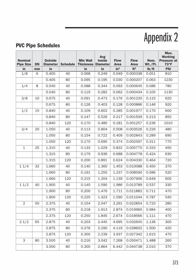
373
NominalPipe Size DN
OutsideDiameter Schedule
Min Wall Thickness
Avg Inside
DiameterFlowArea
FlowArea
Nom. Wt./Ft.
Max. Working
Pressure at 73°F
in mm in in in in2 ft2 lb/ft PSI 1/8 6 0.405 40 0.068 0.249 0.049 0.000338 0.051 810
0.405 80 0.095 0.195 0.030 0.000207 0.063 1230
1/4 8 0.540 40 0.088 0.344 0.093 0.000645 0.086 780
0.540 80 0.119 0.282 0.062 0.000434 0.105 1130
3/8 10 0.675 40 0.091 0.473 0.176 0.001220 0.115 620
0.675 80 0.126 0.403 0.128 0.000886 0.146 920
1/2 15 0.840 40 0.109 0.602 0.285 0.001977 0.170 600
0.840 80 0.147 0.526 0.217 0.001509 0.213 850
0.840 120 0.170 0.480 0.181 0.001257 0.236 1010
3/4 20 1.050 40 0.113 0.804 0.508 0.003526 0.226 480
1.050 80 0.154 0.722 0.409 0.002843 0.289 690
1.050 120 0.170 0.690 0.374 0.002597 0.311 770
1 25 1.315 40 0.133 1.029 0.832 0.005775 0.333 450
1.315 80 0.179 0.936 0.688 0.004778 0.424 630
1.315 120 0.200 0.891 0.624 0.004330 0.464 720
1 1/4 32 1.660 40 0.140 1.360 1.453 0.010088 0.450 370
1.660 80 0.191 1.255 1.237 0.008590 0.586 520
1.660 120 0.215 1.204 1.139 0.007906 0.649 600
1 1/2 40 1.900 40 0.145 1.590 1.986 0.013789 0.537 330
1.900 80 0.200 1.476 1.711 0.011882 0.711 470
1.900 120 0.225 1.423 1.590 0.011044 0.787 540
2 50 2.375 40 0.154 2.047 3.291 0.022854 0.720 280
2.375 80 0.218 1.913 2.874 0.019960 0.984 400
2.375 120 0.250 1.845 2.674 0.018566 1.111 470
2 1/2 65 2.875 40 0.203 2.445 4.695 0.032605 1.136 300
2.875 80 0.276 2.290 4.119 0.028602 1.500 420
2.875 120 0.300 2.239 3.937 0.027342 1.615 470
3 80 3.500 40 0.216 3.042 7.268 0.050471 1.488 260
3.500 80 0.300 2.864 6.442 0.044738 2.010 370
Appendix 2PVC Pipe Schedules
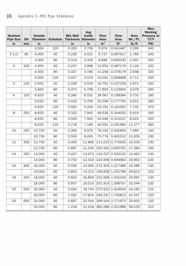
374 A p p e n d i x 2 — P V C P i p e S c h e d u l e s
NominalPipe Size DN
OutsideDiameter Schedule
Min Wall Thickness
Avg Inside
DiameterFlowArea
FlowArea
Nom. Wt./Ft.
Max. Working
Pressure at 73°F
in mm in in in in2 ft2 lb/ft PSI 3.500 120 0.350 2.758 5.974 0.041487 2.306 440
3 1/2 90 4.000 40 0.226 3.521 9.737 0.067617 1.789 240
4.000 80 0.318 3.326 8.688 0.060335 2.452 350
4 100 4.500 40 0.237 3.998 12.554 0.087179 2.118 220
4.500 80 0.337 3.786 11.258 0.078179 2.938 320
4.500 120 0.437 3.574 10.032 0.069668 3.713 430
5 125 5.563 40 0.258 5.016 19.761 0.137228 2.874 190
5.563 80 0.375 4.768 17.855 0.123994 4.078 290
6 150 6.625 40 0.280 6.031 28.567 0.198384 3.733 180
6.625 80 0.432 5.709 25.598 0.177765 5.610 280
6.625 120 0.562 5.434 23.191 0.161052 7.132 370
8 200 8.625 40 0.322 7.942 49.539 0.344022 5.619 160
8.625 80 0.500 7.565 44.948 0.312137 8.522 250
8.625 120 0.718 7.189 40.591 0.281880 11.277 380
10 250 10.750 40 0.365 9.976 78.163 0.542800 7.966 140
10.750 80 0.593 9.493 70.778 0.491512 12.635 230
12 300 12.750 40 0.406 11.889 111.015 0.770935 10.534 130
12.750 80 0.687 11.294 100.181 0.695701 17.384 230
14 350 14.000 40 0.437 13.073 134.227 0.932132 12.462 130
14.000 80 0.750 12.410 120.958 0.839983 20.852 220
16 400 16.000 40 0.500 14.940 175.304 1.217386 16.286 130
16.000 80 0.843 14.213 158.658 1.101789 26.810 220
18 450 18.000 40 0.562 16.809 221.908 1.541029 20.587 130
18.000 80 0.937 16.014 201.414 1.398707 33.544 220
20 500 20.000 40 0.593 18.743 275.910 1.916043 24.183 120
20.000 80 1.031 17.814 249.237 1.730812 41.047 220
24 600 24.000 40 0.687 22.544 399.164 2.771973 33.652 120
24.000 80 1.218 21.418 360.286 2.501986 58.233 210
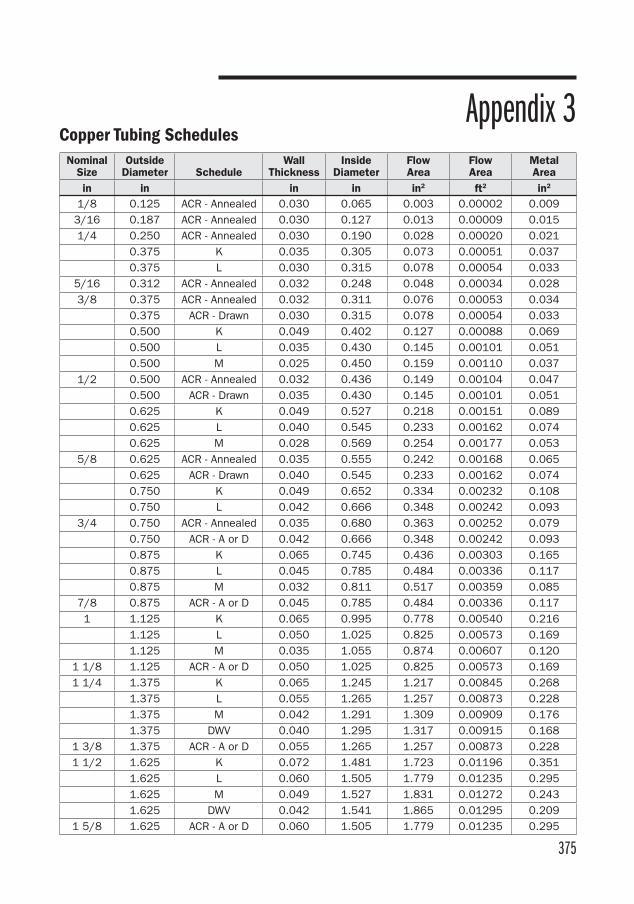
375
NominalSize
OutsideDiameter Schedule
Wall Thickness
InsideDiameter
FlowArea
FlowArea
MetalArea
in in in in in2 ft2 in2
1/8 0.125 ACR - Annealed 0.030 0.065 0.003 0.00002 0.0093/16 0.187 ACR - Annealed 0.030 0.127 0.013 0.00009 0.0151/4 0.250 ACR - Annealed 0.030 0.190 0.028 0.00020 0.021 0.375 K 0.035 0.305 0.073 0.00051 0.037 0.375 L 0.030 0.315 0.078 0.00054 0.033
5/16 0.312 ACR - Annealed 0.032 0.248 0.048 0.00034 0.0283/8 0.375 ACR - Annealed 0.032 0.311 0.076 0.00053 0.034 0.375 ACR - Drawn 0.030 0.315 0.078 0.00054 0.033 0.500 K 0.049 0.402 0.127 0.00088 0.069 0.500 L 0.035 0.430 0.145 0.00101 0.051 0.500 M 0.025 0.450 0.159 0.00110 0.037
1/2 0.500 ACR - Annealed 0.032 0.436 0.149 0.00104 0.047 0.500 ACR - Drawn 0.035 0.430 0.145 0.00101 0.051 0.625 K 0.049 0.527 0.218 0.00151 0.089 0.625 L 0.040 0.545 0.233 0.00162 0.074 0.625 M 0.028 0.569 0.254 0.00177 0.053
5/8 0.625 ACR - Annealed 0.035 0.555 0.242 0.00168 0.065 0.625 ACR - Drawn 0.040 0.545 0.233 0.00162 0.074 0.750 K 0.049 0.652 0.334 0.00232 0.108 0.750 L 0.042 0.666 0.348 0.00242 0.093
3/4 0.750 ACR - Annealed 0.035 0.680 0.363 0.00252 0.079 0.750 ACR - A or D 0.042 0.666 0.348 0.00242 0.093 0.875 K 0.065 0.745 0.436 0.00303 0.165 0.875 L 0.045 0.785 0.484 0.00336 0.117 0.875 M 0.032 0.811 0.517 0.00359 0.085
7/8 0.875 ACR - A or D 0.045 0.785 0.484 0.00336 0.1171 1.125 K 0.065 0.995 0.778 0.00540 0.216 1.125 L 0.050 1.025 0.825 0.00573 0.169 1.125 M 0.035 1.055 0.874 0.00607 0.120
1 1/8 1.125 ACR - A or D 0.050 1.025 0.825 0.00573 0.1691 1/4 1.375 K 0.065 1.245 1.217 0.00845 0.268
1.375 L 0.055 1.265 1.257 0.00873 0.228 1.375 M 0.042 1.291 1.309 0.00909 0.176 1.375 DWV 0.040 1.295 1.317 0.00915 0.168
1 3/8 1.375 ACR - A or D 0.055 1.265 1.257 0.00873 0.2281 1/2 1.625 K 0.072 1.481 1.723 0.01196 0.351
1.625 L 0.060 1.505 1.779 0.01235 0.295 1.625 M 0.049 1.527 1.831 0.01272 0.243 1.625 DWV 0.042 1.541 1.865 0.01295 0.209
1 5/8 1.625 ACR - A or D 0.060 1.505 1.779 0.01235 0.295
Appendix 3Copper Tubing Schedules
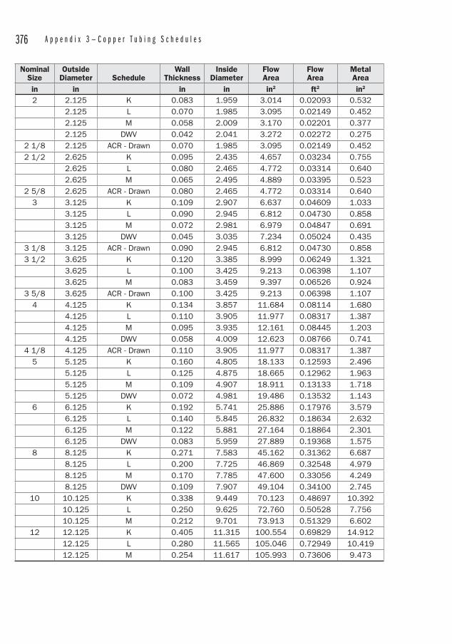
376 A p p e n d i x 3 — C o p p e r T u b i n g S c h e d u l e s
NominalSize
OutsideDiameter Schedule
Wall Thickness
InsideDiameter
FlowArea
FlowArea
MetalArea
in in in in in2 ft2 in2
2 2.125 K 0.083 1.959 3.014 0.02093 0.532 2.125 L 0.070 1.985 3.095 0.02149 0.452 2.125 M 0.058 2.009 3.170 0.02201 0.377 2.125 DWV 0.042 2.041 3.272 0.02272 0.275
2 1/8 2.125 ACR - Drawn 0.070 1.985 3.095 0.02149 0.4522 1/2 2.625 K 0.095 2.435 4.657 0.03234 0.755
2.625 L 0.080 2.465 4.772 0.03314 0.640 2.625 M 0.065 2.495 4.889 0.03395 0.523
2 5/8 2.625 ACR - Drawn 0.080 2.465 4.772 0.03314 0.6403 3.125 K 0.109 2.907 6.637 0.04609 1.033 3.125 L 0.090 2.945 6.812 0.04730 0.858 3.125 M 0.072 2.981 6.979 0.04847 0.691 3.125 DWV 0.045 3.035 7.234 0.05024 0.435
3 1/8 3.125 ACR - Drawn 0.090 2.945 6.812 0.04730 0.8583 1/2 3.625 K 0.120 3.385 8.999 0.06249 1.321
3.625 L 0.100 3.425 9.213 0.06398 1.107 3.625 M 0.083 3.459 9.397 0.06526 0.924
3 5/8 3.625 ACR - Drawn 0.100 3.425 9.213 0.06398 1.1074 4.125 K 0.134 3.857 11.684 0.08114 1.680 4.125 L 0.110 3.905 11.977 0.08317 1.387 4.125 M 0.095 3.935 12.161 0.08445 1.203 4.125 DWV 0.058 4.009 12.623 0.08766 0.741
4 1/8 4.125 ACR - Drawn 0.110 3.905 11.977 0.08317 1.3875 5.125 K 0.160 4.805 18.133 0.12593 2.496 5.125 L 0.125 4.875 18.665 0.12962 1.963 5.125 M 0.109 4.907 18.911 0.13133 1.718 5.125 DWV 0.072 4.981 19.486 0.13532 1.1436 6.125 K 0.192 5.741 25.886 0.17976 3.579 6.125 L 0.140 5.845 26.832 0.18634 2.632 6.125 M 0.122 5.881 27.164 0.18864 2.301 6.125 DWV 0.083 5.959 27.889 0.19368 1.5758 8.125 K 0.271 7.583 45.162 0.31362 6.687 8.125 L 0.200 7.725 46.869 0.32548 4.979 8.125 M 0.170 7.785 47.600 0.33056 4.249 8.125 DWV 0.109 7.907 49.104 0.34100 2.74510 10.125 K 0.338 9.449 70.123 0.48697 10.392 10.125 L 0.250 9.625 72.760 0.50528 7.756 10.125 M 0.212 9.701 73.913 0.51329 6.60212 12.125 K 0.405 11.315 100.554 0.69829 14.912 12.125 L 0.280 11.565 105.046 0.72949 10.419 12.125 M 0.254 11.617 105.993 0.73606 9.473
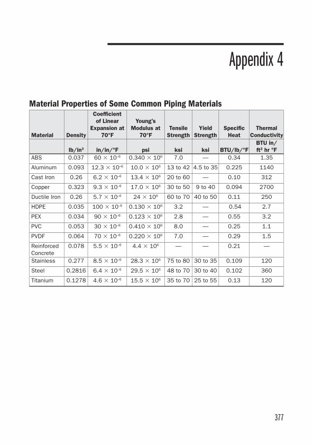
377
Appendix 4
Material Properties of Some Common Piping Materials
Material Density
Coefficientof Linear
Expansion at 70°F
Young’s Modulus at
70°FTensile
StrengthYield
StrengthSpecific
HeatThermal
Conductivity
lb/in3 in/in/°F psi ksi ksi BTU/lb/°FBTU in/ft2 hr °F
ABS 0.037 60 � 10–6 0.340 � 106 7.0 — 0.34 1.35
Aluminum 0.093 12.3 � 10–6 10.0 � 106 13 to 42 4.5 to 35 0.225 1140
Cast Iron 0.26 6.2 � 10–6 13.4 � 106 20 to 60 — 0.10 312
Copper 0.323 9.3 � 10–6 17.0 � 106 30 to 50 9 to 40 0.094 2700
Ductile Iron 0.26 5.7 � 10–6 24 � 106 60 to 70 40 to 50 0.11 250
HDPE 0.035 100 � 10–6 0.130 � 106 3.2 — 0.54 2.7
PEX 0.034 90 � 10–6 0.123 � 106 2.8 — 0.55 3.2
PVC 0.053 30 � 10–6 0.410 � 106 8.0 — 0.25 1.1
PVDF 0.064 70 � 10–6 0.220 � 106 7.0 — 0.29 1.5
ReinforcedConcrete
0.078 5.5 � 10–6 4.4 � 106 — — 0.21 —
Stainless 0.277 8.5 � 10–6 28.3 � 106 75 to 80 30 to 35 0.109 120
Steel 0.2816 6.4 � 10–6 29.5 � 106 48 to 70 30 to 40 0.102 360
Titanium 0.1278 4.6 � 10–6 15.5 � 106 35 to 70 25 to 55 0.13 120

This page intentionally left blank
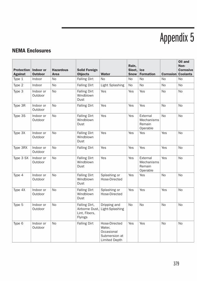
379
Appendix 5NEMA Enclosures
ProtectionAgainst
Indoor or Outdoor
HazardousArea
Solid Foreign Objects Water
Rain, Sleet, Snow
IceFormation Corrosion
Oil and Non-Corrosive Coolants
Type 1 Indoor No Falling Dirt No No No No No
Type 2 Indoor No Falling Dirt Light Splashing No No No No
Type 3 Indoor or Outdoor
No Falling Dirt WindblownDust
Yes Yes Yes No No
Type 3R Indoor or Outdoor
No Falling Dirt Yes Yes Yes No No
Type 3S Indoor or Outdoor
No Falling Dirt WindblownDust
Yes Yes External MechanismsRemainOperable
No No
Type 3X Indoor or Outdoor
No Falling Dirt WindblownDust
Yes Yes Yes Yes No
Type 3RX Indoor or Outdoor
No Falling Dirt Yes Yes Yes Yes No
Type 3 SX Indoor or Outdoor
No Falling Dirt WindblownDust
Yes Yes External MechanismsRemainOperable
Yes No
Type 4 Indoor or Outdoor
No Falling Dirt WindblownDust
Splashing or Hose-Directed
Yes Yes No No
Type 4X Indoor or Outdoor
No Falling Dirt WindblownDust
Splashing or Hose-Directed
Yes Yes Yes No
Type 5 Indoor or Outdoor
No Falling Dirt, Airborne Dust, Lint, Fibers, Flyings
Dripping and Light-Splashing
No No No No
Type 6 Indoor or Outdoor
No Falling Dirt Hose-Directed Water, OccasionalSubmersion at Limited Depth
Yes Yes No No
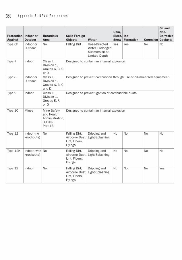
380 A p p e n d i x 5 — N E M A E n c l o s u r e s
ProtectionAgainst
Indoor or Outdoor
HazardousArea
Solid Foreign Objects Water
Rain, Sleet, Snow
IceFormation Corrosion
Oil and Non-Corrosive Coolants
Type 6P Indoor or Outdoor
No Falling Dirt Hose-Directed Water, Prolonged Submersion at Limited Depth
Yes Yes No No
Type 7 Indoor Class I, Division 1, Groups A, B, C, or D
Designed to contain an internal explosion
Type 8 Indoor or Outdoor
Class I, Division 1, Groups A, B, C, and D
Designed to prevent combustion through use of oil-immersed equipment
Type 9 Indoor Class II, Division 1, Groups E, F, or G
Designed to prevent ignition of combustible dusts
Type 10 Mines Mine Safety and Health Administration, 30 CFR, Part 18
Designed to contain an internal explosion
Type 12 Indoor (no knockouts)
No Falling Dirt, Airborne Dust, Lint, Fibers, Flyings
Dripping and Light-Splashing
No No No No
Type 12K Indoor (with knockouts)
No Falling Dirt, Airborne Dust, Lint, Fibers, Flyings
Dripping and Light-Splashing
No No No No
Type 13 Indoor No Falling Dirt, Airborne Dust, Lint, Fibers, Flyings
Dripping and Light-Splashing
No No No Yes

381
Appendix 6
IP Codes for Electrical Enclosures
IP Number Solids (First Numeral) Liquids (Second Numeral)
0 No protection against contact or entry of solids.
No protection.
1 Protection against accidental contact by hand, but not deliberate contact. Protection against large object (greater than 50mm)
Protection against drops of condensed water. Condensed water falling on housing shall have no effect.
2 Protection against contact by fingers.Protection against medium-size foreign objects (greater than 12mm)
Protection against drops of liquid. Drops of falling liquid shall have no effect when housing is tilted to 15 degrees from vertical.
3 Protection against contact by tools, wire, etc. Protection against small foreign objects (greater than 2.5 mm)
Protection against rain. No harmful effect from rain at angle less than 60 degrees from vertical.
4 Protection against contact by small tools and wires. Protection against small foreign objects (greater than 1mm)
Protection against splashing from any direction.
5 Complete protection against contact with live or moving parts. Protection against harmful deposits of dust.
Protection against water jets from any direction.
6 Complete protection of live or moving parts. Protection against penetration of dust.
Protection against conditions on ships’ decks. Water from heavy seas will not enter.
7 Protection against immersion in water. Water will not enter under stated conditions of pressure and time.
8 Protection against indefinite immersion in water under a specified pressure.
IP (International Protection Rating) Codes are analogous to the NEMA ratings used in the U.S. The IP Code is defined in IEC 60529. It consists of the letters IP followed by two numerals. The first numeral describes the enclosure’s level of protection against solid foreign objects and the second numeral describes the enclosure’s level of protection against liquids.

This page intentionally left blank
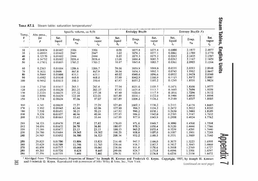
383
Appendix 7Steam
Tables, English Units
TABLE A7.1 Steam table: saturation temperatures1
(continued on next page)
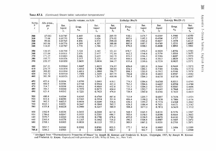
384 Appendix 7—
Steam Tables, English U
nitsTABLE A7.1 (Continued) Steam table: saturation temperatures1
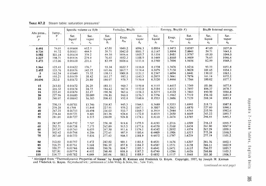
Appendix 7—
Steam Tables, English Units
385TABLE A7.2 Steam table: saturation pressures1
(continued on next page)
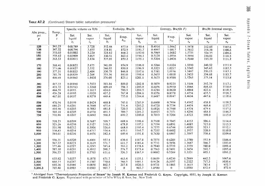
386 Appendix 7—
Steam Tables, English U
nitsTABLE A7.2 (Continued) Steam table: saturation pressures1
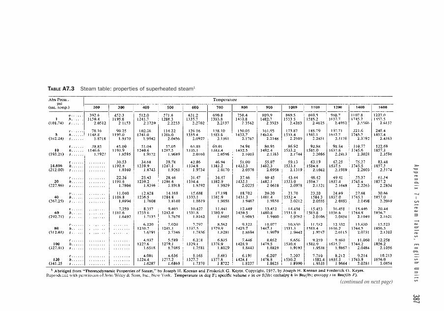
Appendix 7—
Steam Tables, English Units
387
(continued on next page)
TABLE A7.3 Steam table: properties of superheated steam1
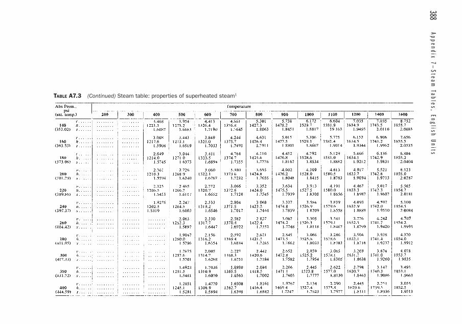
388 Appendix 7—
Steam Tables, English U
nits
TABLE A7.3 (Continued) Steam table: properties of superheated steam1

Appendix 7—
Steam Tables, English Units
389
(continued on next page)
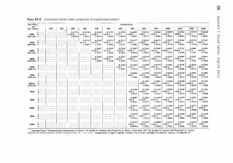
390 Appendix 7—
Steam Tables, English U
nitsTABLE A7.3 (Continued) Steam table: properties of superheated steam1
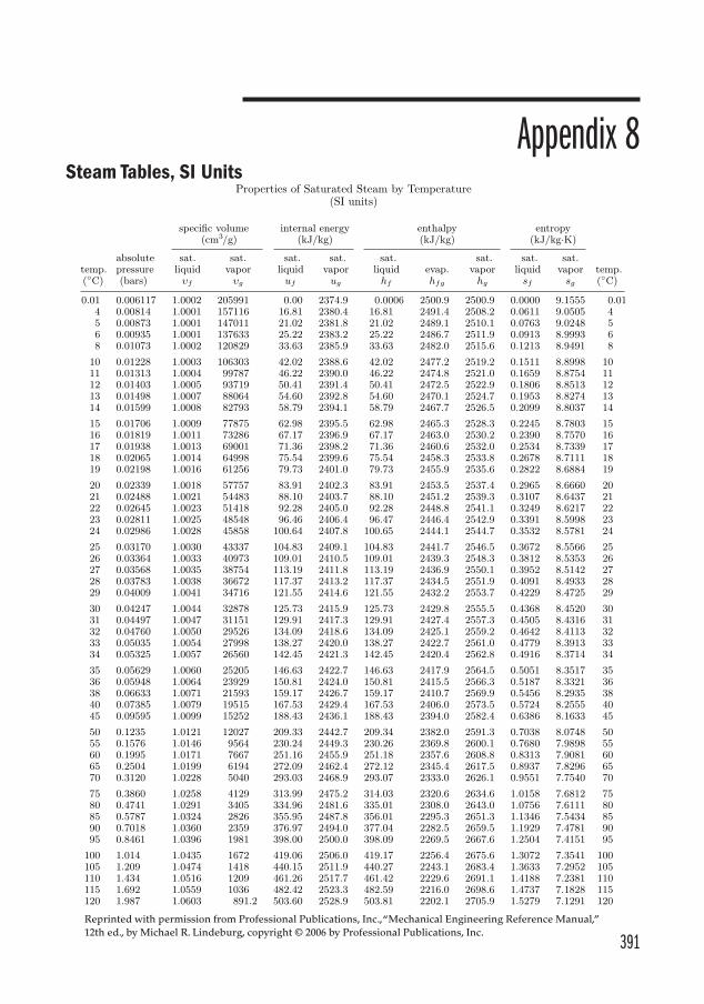
391
Appendix 8Steam Tables, SI Units
Properties of Saturated Steam by Temperature(SI units)
specific volume internal energy enthalpy entropy(cm3/g) (kJ/kg) (kJ/kg) (kJ/kg·K)
absolute sat. sat. sat. sat. sat. sat. sat. sat.temp. pressure liquid vapor liquid vapor liquid evap. vapor liquid vapor temp.(◦C) (bars) υf υg uf ug hf hfg hg sf sg (◦C)
0.01 0.006117 1.0002 205991 0.00 2374.9 0.0006 2500.9 2500.9 0.0000 9.1555 0.014 0.00814 1.0001 157116 16.81 2380.4 16.81 2491.4 2508.2 0.0611 9.0505 45 0.00873 1.0001 147011 21.02 2381.8 21.02 2489.1 2510.1 0.0763 9.0248 56 0.00935 1.0001 137633 25.22 2383.2 25.22 2486.7 2511.9 0.0913 8.9993 68 0.01073 1.0002 120829 33.63 2385.9 33.63 2482.0 2515.6 0.1213 8.9491 8
10 0.01228 1.0003 106303 42.02 2388.6 42.02 2477.2 2519.2 0.1511 8.8998 1011 0.01313 1.0004 99787 46.22 2390.0 46.22 2474.8 2521.0 0.1659 8.8754 1112 0.01403 1.0005 93719 50.41 2391.4 50.41 2472.5 2522.9 0.1806 8.8513 1213 0.01498 1.0007 88064 54.60 2392.8 54.60 2470.1 2524.7 0.1953 8.8274 1314 0.01599 1.0008 82793 58.79 2394.1 58.79 2467.7 2526.5 0.2099 8.8037 14
15 0.01706 1.0009 77875 62.98 2395.5 62.98 2465.3 2528.3 0.2245 8.7803 1516 0.01819 1.0011 73286 67.17 2396.9 67.17 2463.0 2530.2 0.2390 8.7570 1617 0.01938 1.0013 69001 71.36 2398.2 71.36 2460.6 2532.0 0.2534 8.7339 1718 0.02065 1.0014 64998 75.54 2399.6 75.54 2458.3 2533.8 0.2678 8.7111 1819 0.02198 1.0016 61256 79.73 2401.0 79.73 2455.9 2535.6 0.2822 8.6884 19
20 0.02339 1.0018 57757 83.91 2402.3 83.91 2453.5 2537.4 0.2965 8.6660 2021 0.02488 1.0021 54483 88.10 2403.7 88.10 2451.2 2539.3 0.3107 8.6437 2122 0.02645 1.0023 51418 92.28 2405.0 92.28 2448.8 2541.1 0.3249 8.6217 2223 0.02811 1.0025 48548 96.46 2406.4 96.47 2446.4 2542.9 0.3391 8.5998 2324 0.02986 1.0028 45858 100.64 2407.8 100.65 2444.1 2544.7 0.3532 8.5781 24
25 0.03170 1.0030 43337 104.83 2409.1 104.83 2441.7 2546.5 0.3672 8.5566 2526 0.03364 1.0033 40973 109.01 2410.5 109.01 2439.3 2548.3 0.3812 8.5353 2627 0.03568 1.0035 38754 113.19 2411.8 113.19 2436.9 2550.1 0.3952 8.5142 2728 0.03783 1.0038 36672 117.37 2413.2 117.37 2434.5 2551.9 0.4091 8.4933 2829 0.04009 1.0041 34716 121.55 2414.6 121.55 2432.2 2553.7 0.4229 8.4725 29
30 0.04247 1.0044 32878 125.73 2415.9 125.73 2429.8 2555.5 0.4368 8.4520 3031 0.04497 1.0047 31151 129.91 2417.3 129.91 2427.4 2557.3 0.4505 8.4316 3132 0.04760 1.0050 29526 134.09 2418.6 134.09 2425.1 2559.2 0.4642 8.4113 3233 0.05035 1.0054 27998 138.27 2420.0 138.27 2422.7 2561.0 0.4779 8.3913 3334 0.05325 1.0057 26560 142.45 2421.3 142.45 2420.4 2562.8 0.4916 8.3714 34
35 0.05629 1.0060 25205 146.63 2422.7 146.63 2417.9 2564.5 0.5051 8.3517 3536 0.05948 1.0064 23929 150.81 2424.0 150.81 2415.5 2566.3 0.5187 8.3321 3638 0.06633 1.0071 21593 159.17 2426.7 159.17 2410.7 2569.9 0.5456 8.2935 3840 0.07385 1.0079 19515 167.53 2429.4 167.53 2406.0 2573.5 0.5724 8.2555 4045 0.09595 1.0099 15252 188.43 2436.1 188.43 2394.0 2582.4 0.6386 8.1633 45
50 0.1235 1.0121 12027 209.33 2442.7 209.34 2382.0 2591.3 0.7038 8.0748 5055 0.1576 1.0146 9564 230.24 2449.3 230.26 2369.8 2600.1 0.7680 7.9898 5560 0.1995 1.0171 7667 251.16 2455.9 251.18 2357.6 2608.8 0.8313 7.9081 6065 0.2504 1.0199 6194 272.09 2462.4 272.12 2345.4 2617.5 0.8937 7.8296 6570 0.3120 1.0228 5040 293.03 2468.9 293.07 2333.0 2626.1 0.9551 7.7540 70
75 0.3860 1.0258 4129 313.99 2475.2 314.03 2320.6 2634.6 1.0158 7.6812 7580 0.4741 1.0291 3405 334.96 2481.6 335.01 2308.0 2643.0 1.0756 7.6111 8085 0.5787 1.0324 2826 355.95 2487.8 356.01 2295.3 2651.3 1.1346 7.5434 8590 0.7018 1.0360 2359 376.97 2494.0 377.04 2282.5 2659.5 1.1929 7.4781 9095 0.8461 1.0396 1981 398.00 2500.0 398.09 2269.5 2667.6 1.2504 7.4151 95
100 1.014 1.0435 1672 419.06 2506.0 419.17 2256.4 2675.6 1.3072 7.3541 100105 1.209 1.0474 1418 440.15 2511.9 440.27 2243.1 2683.4 1.3633 7.2952 105110 1.434 1.0516 1209 461.26 2517.7 461.42 2229.6 2691.1 1.4188 7.2381 110115 1.692 1.0559 1036 482.42 2523.3 482.59 2216.0 2698.6 1.4737 7.1828 115120 1.987 1.0603 891.2 503.60 2528.9 503.81 2202.1 2705.9 1.5279 7.1291 120
Reprinted with permission from Professional Publications, Inc., “Mechanical Engineering Reference Manual,” 12th ed., by Michael R. Lindeburg, copyright © 2006 by Professional Publications, Inc.
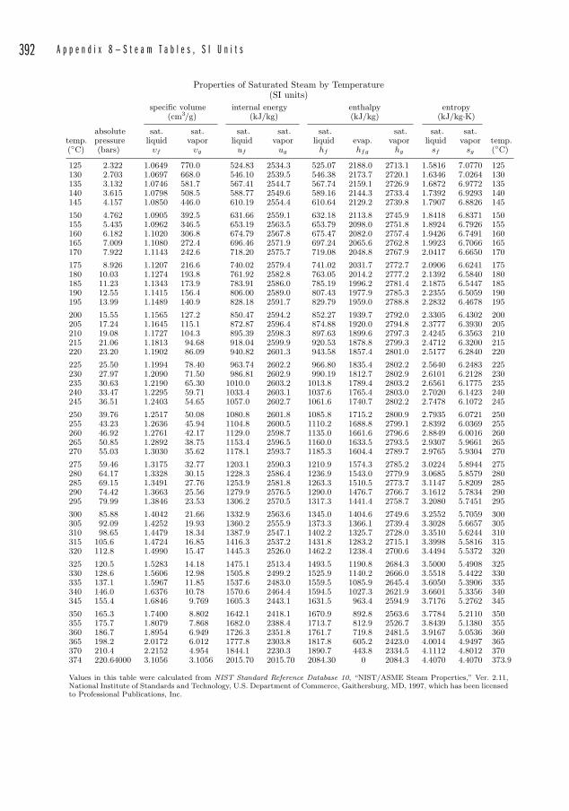
392 A p p e n d i x 8 — S t e a m T a b l e s , S I U n i t s
Properties of Saturated Steam by Temperature(SI units)
specific volume internal energy enthalpy entropy(cm3/g) (kJ/kg) (kJ/kg) (kJ/kg·K)
absolute sat. sat. sat. sat. sat. sat. sat. sat.temp. pressure liquid vapor liquid vapor liquid evap. vapor liquid vapor temp.(◦C) (bars) υf υg uf ug hf hfg hg sf sg (◦C)
125 2.322 1.0649 770.0 524.83 2534.3 525.07 2188.0 2713.1 1.5816 7.0770 125130 2.703 1.0697 668.0 546.10 2539.5 546.38 2173.7 2720.1 1.6346 7.0264 130135 3.132 1.0746 581.7 567.41 2544.7 567.74 2159.1 2726.9 1.6872 6.9772 135140 3.615 1.0798 508.5 588.77 2549.6 589.16 2144.3 2733.4 1.7392 6.9293 140145 4.157 1.0850 446.0 610.19 2554.4 610.64 2129.2 2739.8 1.7907 6.8826 145
150 4.762 1.0905 392.5 631.66 2559.1 632.18 2113.8 2745.9 1.8418 6.8371 150155 5.435 1.0962 346.5 653.19 2563.5 653.79 2098.0 2751.8 1.8924 6.7926 155160 6.182 1.1020 306.8 674.79 2567.8 675.47 2082.0 2757.4 1.9426 6.7491 160165 7.009 1.1080 272.4 696.46 2571.9 697.24 2065.6 2762.8 1.9923 6.7066 165170 7.922 1.1143 242.6 718.20 2575.7 719.08 2048.8 2767.9 2.0417 6.6650 170
175 8.926 1.1207 216.6 740.02 2579.4 741.02 2031.7 2772.7 2.0906 6.6241 175180 10.03 1.1274 193.8 761.92 2582.8 763.05 2014.2 2777.2 2.1392 6.5840 180185 11.23 1.1343 173.9 783.91 2586.0 785.19 1996.2 2781.4 2.1875 6.5447 185190 12.55 1.1415 156.4 806.00 2589.0 807.43 1977.9 2785.3 2.2355 6.5059 190195 13.99 1.1489 140.9 828.18 2591.7 829.79 1959.0 2788.8 2.2832 6.4678 195
200 15.55 1.1565 127.2 850.47 2594.2 852.27 1939.7 2792.0 2.3305 6.4302 200205 17.24 1.1645 115.1 872.87 2596.4 874.88 1920.0 2794.8 2.3777 6.3930 205210 19.08 1.1727 104.3 895.39 2598.3 897.63 1899.6 2797.3 2.4245 6.3563 210215 21.06 1.1813 94.68 918.04 2599.9 920.53 1878.8 2799.3 2.4712 6.3200 215220 23.20 1.1902 86.09 940.82 2601.3 943.58 1857.4 2801.0 2.5177 6.2840 220
225 25.50 1.1994 78.40 963.74 2602.2 966.80 1835.4 2802.2 2.5640 6.2483 225230 27.97 1.2090 71.50 986.81 2602.9 990.19 1812.7 2802.9 2.6101 6.2128 230235 30.63 1.2190 65.30 1010.0 2603.2 1013.8 1789.4 2803.2 2.6561 6.1775 235240 33.47 1.2295 59.71 1033.4 2603.1 1037.6 1765.4 2803.0 2.7020 6.1423 240245 36.51 1.2403 54.65 1057.0 2602.7 1061.6 1740.7 2802.2 2.7478 6.1072 245
250 39.76 1.2517 50.08 1080.8 2601.8 1085.8 1715.2 2800.9 2.7935 6.0721 250255 43.23 1.2636 45.94 1104.8 2600.5 1110.2 1688.8 2799.1 2.8392 6.0369 255260 46.92 1.2761 42.17 1129.0 2598.7 1135.0 1661.6 2796.6 2.8849 6.0016 260265 50.85 1.2892 38.75 1153.4 2596.5 1160.0 1633.5 2793.5 2.9307 5.9661 265270 55.03 1.3030 35.62 1178.1 2593.7 1185.3 1604.4 2789.7 2.9765 5.9304 270
275 59.46 1.3175 32.77 1203.1 2590.3 1210.9 1574.3 2785.2 3.0224 5.8944 275280 64.17 1.3328 30.15 1228.3 2586.4 1236.9 1543.0 2779.9 3.0685 5.8579 280285 69.15 1.3491 27.76 1253.9 2581.8 1263.3 1510.5 2773.7 3.1147 5.8209 285290 74.42 1.3663 25.56 1279.9 2576.5 1290.0 1476.7 2766.7 3.1612 5.7834 290295 79.99 1.3846 23.53 1306.2 2570.5 1317.3 1441.4 2758.7 3.2080 5.7451 295
300 85.88 1.4042 21.66 1332.9 2563.6 1345.0 1404.6 2749.6 3.2552 5.7059 300305 92.09 1.4252 19.93 1360.2 2555.9 1373.3 1366.1 2739.4 3.3028 5.6657 305310 98.65 1.4479 18.34 1387.9 2547.1 1402.2 1325.7 2728.0 3.3510 5.6244 310315 105.6 1.4724 16.85 1416.3 2537.2 1431.8 1283.2 2715.1 3.3998 5.5816 315320 112.8 1.4990 15.47 1445.3 2526.0 1462.2 1238.4 2700.6 3.4494 5.5372 320
325 120.5 1.5283 14.18 1475.1 2513.4 1493.5 1190.8 2684.3 3.5000 5.4908 325330 128.6 1.5606 12.98 1505.8 2499.2 1525.9 1140.2 2666.0 3.5518 5.4422 330335 137.1 1.5967 11.85 1537.6 2483.0 1559.5 1085.9 2645.4 3.6050 5.3906 335340 146.0 1.6376 10.78 1570.6 2464.4 1594.5 1027.3 2621.9 3.6601 5.3356 340345 155.4 1.6846 9.769 1605.3 2443.1 1631.5 963.4 2594.9 3.7176 5.2762 345
350 165.3 1.7400 8.802 1642.1 2418.1 1670.9 892.8 2563.6 3.7784 5.2110 350355 175.7 1.8079 7.868 1682.0 2388.4 1713.7 812.9 2526.7 3.8439 5.1380 355360 186.7 1.8954 6.949 1726.3 2351.8 1761.7 719.8 2481.5 3.9167 5.0536 360365 198.2 2.0172 6.012 1777.8 2303.8 1817.8 605.2 2423.0 4.0014 4.9497 365370 210.4 2.2152 4.954 1844.1 2230.3 1890.7 443.8 2334.5 4.1112 4.8012 370374 220.64000 3.1056 3.1056 2015.70 2015.70 2084.30 0 2084.3 4.4070 4.4070 373.9
Values in this table were calculated from NIST Standard Reference Database 10, “NIST/ASME Steam Properties,” Ver. 2.11,National Institute of Standards and Technology, U.S. Department of Commerce, Gaithersburg, MD, 1997, which has been licensedto Professional Publications, Inc.
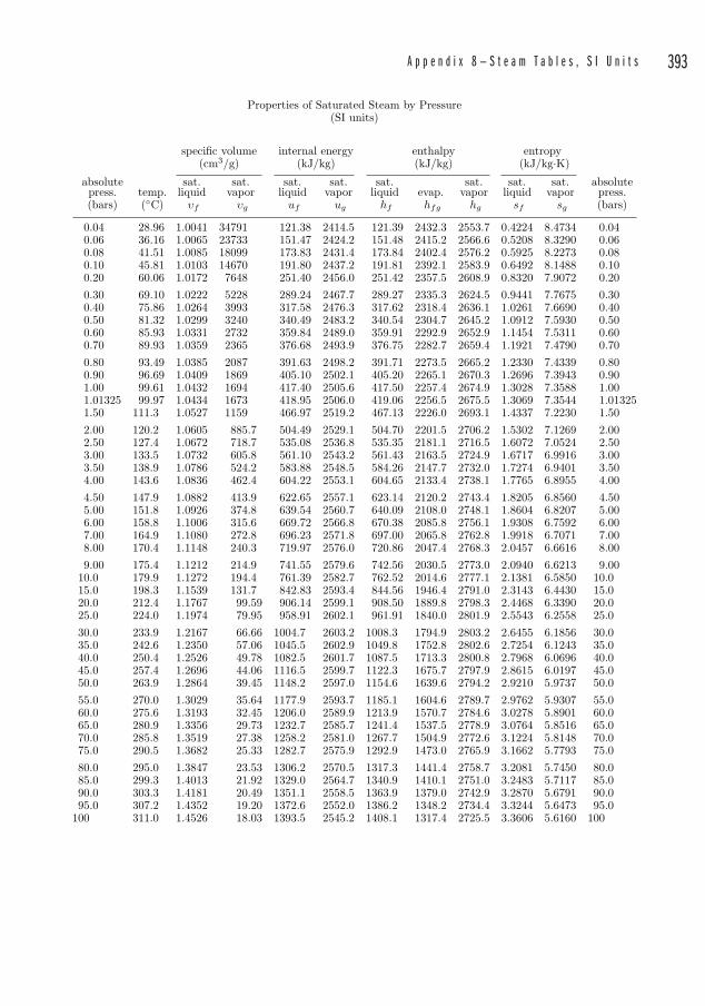
A p p e n d i x 8 — S t e a m T a b l e s , S I U n i t s 393
Properties of Saturated Steam by Pressure(SI units)
specific volume internal energy enthalpy entropy(cm3/g) (kJ/kg) (kJ/kg) (kJ/kg·K)
absolute sat. sat. sat. sat. sat. sat. sat. sat. absolutepress. temp. liquid vapor liquid vapor liquid evap. vapor liquid vapor press.(bars) (◦C) υf υg uf ug hf hfg hg sf sg (bars)
0.04 28.96 1.0041 34791 121.38 2414.5 121.39 2432.3 2553.7 0.4224 8.4734 0.040.06 36.16 1.0065 23733 151.47 2424.2 151.48 2415.2 2566.6 0.5208 8.3290 0.060.08 41.51 1.0085 18099 173.83 2431.4 173.84 2402.4 2576.2 0.5925 8.2273 0.080.10 45.81 1.0103 14670 191.80 2437.2 191.81 2392.1 2583.9 0.6492 8.1488 0.100.20 60.06 1.0172 7648 251.40 2456.0 251.42 2357.5 2608.9 0.8320 7.9072 0.200.30 69.10 1.0222 5228 289.24 2467.7 289.27 2335.3 2624.5 0.9441 7.7675 0.300.40 75.86 1.0264 3993 317.58 2476.3 317.62 2318.4 2636.1 1.0261 7.6690 0.400.50 81.32 1.0299 3240 340.49 2483.2 340.54 2304.7 2645.2 1.0912 7.5930 0.500.60 85.93 1.0331 2732 359.84 2489.0 359.91 2292.9 2652.9 1.1454 7.5311 0.600.70 89.93 1.0359 2365 376.68 2493.9 376.75 2282.7 2659.4 1.1921 7.4790 0.700.80 93.49 1.0385 2087 391.63 2498.2 391.71 2273.5 2665.2 1.2330 7.4339 0.800.90 96.69 1.0409 1869 405.10 2502.1 405.20 2265.1 2670.3 1.2696 7.3943 0.901.00 99.61 1.0432 1694 417.40 2505.6 417.50 2257.4 2674.9 1.3028 7.3588 1.001.01325 99.97 1.0434 1673 418.95 2506.0 419.06 2256.5 2675.5 1.3069 7.3544 1.013251.50 111.3 1.0527 1159 466.97 2519.2 467.13 2226.0 2693.1 1.4337 7.2230 1.502.00 120.2 1.0605 885.7 504.49 2529.1 504.70 2201.5 2706.2 1.5302 7.1269 2.002.50 127.4 1.0672 718.7 535.08 2536.8 535.35 2181.1 2716.5 1.6072 7.0524 2.503.00 133.5 1.0732 605.8 561.10 2543.2 561.43 2163.5 2724.9 1.6717 6.9916 3.003.50 138.9 1.0786 524.2 583.88 2548.5 584.26 2147.7 2732.0 1.7274 6.9401 3.504.00 143.6 1.0836 462.4 604.22 2553.1 604.65 2133.4 2738.1 1.7765 6.8955 4.004.50 147.9 1.0882 413.9 622.65 2557.1 623.14 2120.2 2743.4 1.8205 6.8560 4.505.00 151.8 1.0926 374.8 639.54 2560.7 640.09 2108.0 2748.1 1.8604 6.8207 5.006.00 158.8 1.1006 315.6 669.72 2566.8 670.38 2085.8 2756.1 1.9308 6.7592 6.007.00 164.9 1.1080 272.8 696.23 2571.8 697.00 2065.8 2762.8 1.9918 6.7071 7.008.00 170.4 1.1148 240.3 719.97 2576.0 720.86 2047.4 2768.3 2.0457 6.6616 8.009.00 175.4 1.1212 214.9 741.55 2579.6 742.56 2030.5 2773.0 2.0940 6.6213 9.00
10.0 179.9 1.1272 194.4 761.39 2582.7 762.52 2014.6 2777.1 2.1381 6.5850 10.015.0 198.3 1.1539 131.7 842.83 2593.4 844.56 1946.4 2791.0 2.3143 6.4430 15.020.0 212.4 1.1767 99.59 906.14 2599.1 908.50 1889.8 2798.3 2.4468 6.3390 20.025.0 224.0 1.1974 79.95 958.91 2602.1 961.91 1840.0 2801.9 2.5543 6.2558 25.030.0 233.9 1.2167 66.66 1004.7 2603.2 1008.3 1794.9 2803.2 2.6455 6.1856 30.035.0 242.6 1.2350 57.06 1045.5 2602.9 1049.8 1752.8 2802.6 2.7254 6.1243 35.040.0 250.4 1.2526 49.78 1082.5 2601.7 1087.5 1713.3 2800.8 2.7968 6.0696 40.045.0 257.4 1.2696 44.06 1116.5 2599.7 1122.3 1675.7 2797.9 2.8615 6.0197 45.050.0 263.9 1.2864 39.45 1148.2 2597.0 1154.6 1639.6 2794.2 2.9210 5.9737 50.055.0 270.0 1.3029 35.64 1177.9 2593.7 1185.1 1604.6 2789.7 2.9762 5.9307 55.060.0 275.6 1.3193 32.45 1206.0 2589.9 1213.9 1570.7 2784.6 3.0278 5.8901 60.065.0 280.9 1.3356 29.73 1232.7 2585.7 1241.4 1537.5 2778.9 3.0764 5.8516 65.070.0 285.8 1.3519 27.38 1258.2 2581.0 1267.7 1504.9 2772.6 3.1224 5.8148 70.075.0 290.5 1.3682 25.33 1282.7 2575.9 1292.9 1473.0 2765.9 3.1662 5.7793 75.080.0 295.0 1.3847 23.53 1306.2 2570.5 1317.3 1441.4 2758.7 3.2081 5.7450 80.085.0 299.3 1.4013 21.92 1329.0 2564.7 1340.9 1410.1 2751.0 3.2483 5.7117 85.090.0 303.3 1.4181 20.49 1351.1 2558.5 1363.9 1379.0 2742.9 3.2870 5.6791 90.095.0 307.2 1.4352 19.20 1372.6 2552.0 1386.2 1348.2 2734.4 3.3244 5.6473 95.0
100 311.0 1.4526 18.03 1393.5 2545.2 1408.1 1317.4 2725.5 3.3606 5.6160 100
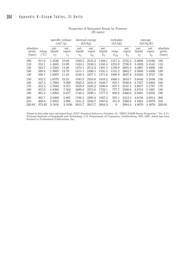
394 A p p e n d i x 8 — S t e a m T a b l e s , S I U n i t s
Properties of Saturated Steam by Pressure(SI units)
specific volume internal energy enthalpy entropy(cm3/g) (kJ/kg) (kJ/kg) (kJ/kg·K)
absolute sat. sat. sat. sat. sat. sat. sat. sat. absolutepress. temp. liquid vapor liquid vapor liquid evap. vapor liquid vapor press.(bars) (◦C) υf υg uf ug hf hfg hg sf sg (bars)
100 311.0 1.4526 18.03 1393.5 2545.2 1408.1 1317.4 2725.5 3.3606 5.6160 100110 318.1 1.4885 15.99 1434.1 2530.5 1450.4 1255.9 2706.3 3.4303 5.5545 110120 324.7 1.5263 14.26 1473.1 2514.3 1491.5 1193.9 2685.4 3.4967 5.4939 120130 330.9 1.5665 12.78 1511.1 2496.5 1531.5 1131.2 2662.7 3.5608 5.4336 130140 336.7 1.6097 11.49 1548.4 2477.1 1571.0 1066.9 2637.9 3.6232 5.3727 140150 342.2 1.6570 10.34 1585.3 2455.6 1610.2 1000.5 2610.7 3.6846 5.3106 150160 347.4 1.7094 9.309 1622.3 2431.8 1649.7 931.1 2580.8 3.7457 5.2463 160170 352.3 1.7693 8.371 1659.9 2405.2 1690.0 857.5 2547.5 3.8077 5.1787 170180 357.0 1.8398 7.502 1699.0 2374.8 1732.1 777.7 2509.8 3.8718 5.1061 180190 361.5 1.9268 6.677 1740.5 2339.1 1777.2 688.8 2466.0 3.9401 5.0256 190200 365.7 2.0400 5.865 1786.4 2295.0 1827.2 585.1 2412.3 4.0156 4.9314 200210 369.8 2.2055 4.996 1841.2 2233.7 1887.6 451.0 2338.6 4.1064 4.8079 210220.64 373.95 3.1056 3.1056 2015.7 2015.7 2084.3 0 2084.3 4.4070 4.4070 220.64
Values in this table were calculated from NIST Standard Reference Database 10, “NIST/ASME Steam Properties,” Ver. 2.11,National Institute of Standards and Technology, U.S. Department of Commerce, Gaithersburg, MD, 1997, which has beenlicensed to Professional Publications, Inc.
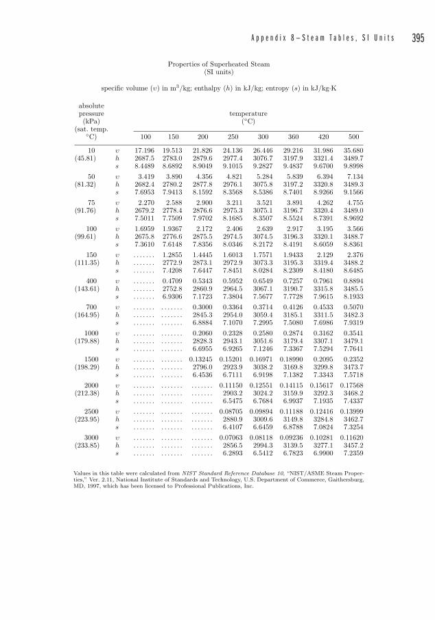
A p p e n d i x 8 — S t e a m T a b l e s , S I U n i t s 395
Properties of Superheated Steam(SI units)
specific volume (υ) in m3/kg; enthalpy (h) in kJ/kg; entropy (s) in kJ/kg·K
absolutepressure temperature(kPa) (◦C)
(sat. temp.◦C) 100 150 200 250 300 360 420 500
10 υ 17.196 19.513 21.826 24.136 26.446 29.216 31.986 35.680(45.81) h 2687.5 2783.0 2879.6 2977.4 3076.7 3197.9 3321.4 3489.7
s 8.4489 8.6892 8.9049 9.1015 9.2827 9.4837 9.6700 9.899850 υ 3.419 3.890 4.356 4.821 5.284 5.839 6.394 7.134
(81.32) h 2682.4 2780.2 2877.8 2976.1 3075.8 3197.2 3320.8 3489.3s 7.6953 7.9413 8.1592 8.3568 8.5386 8.7401 8.9266 9.1566
75 υ 2.270 2.588 2.900 3.211 3.521 3.891 4.262 4.755(91.76) h 2679.2 2778.4 2876.6 2975.3 3075.1 3196.7 3320.4 3489.0
s 7.5011 7.7509 7.9702 8.1685 8.3507 8.5524 8.7391 8.9692100 υ 1.6959 1.9367 2.172 2.406 2.639 2.917 3.195 3.566
(99.61) h 2675.8 2776.6 2875.5 2974.5 3074.5 3196.3 3320.1 3488.7s 7.3610 7.6148 7.8356 8.0346 8.2172 8.4191 8.6059 8.8361
150 υ . . . . . . . 1.2855 1.4445 1.6013 1.7571 1.9433 2.129 2.376(111.35) h . . . . . . . 2772.9 2873.1 2972.9 3073.3 3195.3 3319.4 3488.2
s . . . . . . . 7.4208 7.6447 7.8451 8.0284 8.2309 8.4180 8.6485400 υ . . . . . . . 0.4709 0.5343 0.5952 0.6549 0.7257 0.7961 0.8894
(143.61) h . . . . . . . 2752.8 2860.9 2964.5 3067.1 3190.7 3315.8 3485.5s . . . . . . . 6.9306 7.1723 7.3804 7.5677 7.7728 7.9615 8.1933
700 υ . . . . . . . . . . . . . . 0.3000 0.3364 0.3714 0.4126 0.4533 0.5070(164.95) h . . . . . . . . . . . . . . 2845.3 2954.0 3059.4 3185.1 3311.5 3482.3
s . . . . . . . . . . . . . . 6.8884 7.1070 7.2995 7.5080 7.6986 7.93191000 υ . . . . . . . . . . . . . . 0.2060 0.2328 0.2580 0.2874 0.3162 0.3541
(179.88) h . . . . . . . . . . . . . . 2828.3 2943.1 3051.6 3179.4 3307.1 3479.1s . . . . . . . . . . . . . . 6.6955 6.9265 7.1246 7.3367 7.5294 7.7641
1500 υ . . . . . . . . . . . . . . 0.13245 0.15201 0.16971 0.18990 0.2095 0.2352(198.29) h . . . . . . . . . . . . . . 2796.0 2923.9 3038.2 3169.8 3299.8 3473.7
s . . . . . . . . . . . . . . 6.4536 6.7111 6.9198 7.1382 7.3343 7.57182000 υ . . . . . . . . . . . . . . . . . . . . . 0.11150 0.12551 0.14115 0.15617 0.17568
(212.38) h . . . . . . . . . . . . . . . . . . . . . 2903.2 3024.2 3159.9 3292.3 3468.2s . . . . . . . . . . . . . . . . . . . . . 6.5475 6.7684 6.9937 7.1935 7.4337
2500 υ . . . . . . . . . . . . . . . . . . . . . 0.08705 0.09894 0.11188 0.12416 0.13999(223.95) h . . . . . . . . . . . . . . . . . . . . . 2880.9 3009.6 3149.8 3284.8 3462.7
s . . . . . . . . . . . . . . . . . . . . . 6.4107 6.6459 6.8788 7.0824 7.32543000 υ . . . . . . . . . . . . . . . . . . . . . 0.07063 0.08118 0.09236 0.10281 0.11620
(233.85) h . . . . . . . . . . . . . . . . . . . . . 2856.5 2994.3 3139.5 3277.1 3457.2s . . . . . . . . . . . . . . . . . . . . . 6.2893 6.5412 6.7823 6.9900 7.2359
Values in this table were calculated from NIST Standard Reference Database 10, “NIST/ASME Steam Proper-ties,” Ver. 2.11, National Institute of Standards and Technology, U.S. Department of Commerce, Gaithersburg,MD, 1997, which has been licensed to Professional Publications, Inc.

This page intentionally left blank

397
Appendix 9
Friction LossesNote: Friction losses are given in ft per 100 ft (“cft” � 100 ft)
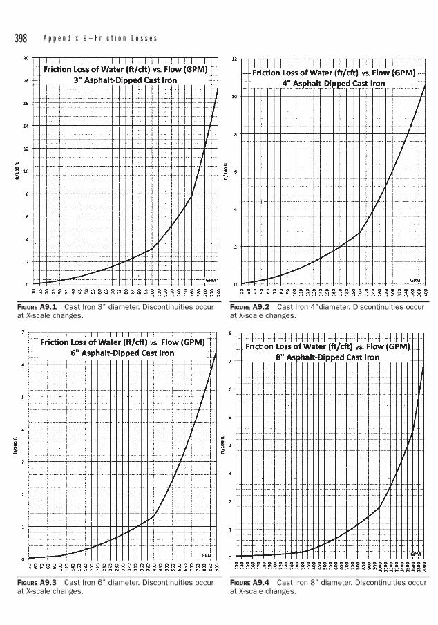
398 A p p e n d i x 9 — F r i c t i o n L o s s e s
FIGURE A9.1 Cast Iron 3” diameter. Discontinuities occur at X-scale changes.
FIGURE A9.2 Cast Iron 4”diameter. Discontinuities occur at X-scale changes.
FIGURE A9.3 Cast Iron 6” diameter. Discontinuities occur at X-scale changes.
FIGURE A9.4 Cast Iron 8” diameter. Discontinuities occur at X-scale changes.
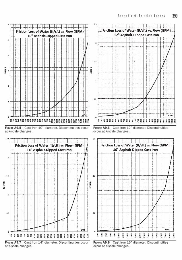
A p p e n d i x 9 — F r i c t i o n L o s s e s 399
FIGURE A9.5 Cast Iron 10” diameter. Discontinuities occur at X-scale changes.
FIGURE A9.6 Cast Iron 12” diameter. Discontinuities occur at X-scale changes.
FIGURE A9.7 Cast Iron 14” diameter. Discontinuities occur at X-scale changes.
FIGURE A9.8 Cast Iron 16” diameter. Discontinuities occur at X-scale changes.
400 A p p e n d i x 9 — F r i c t i o n L o s s e s
FIGURE A9.9 Cast Iron 18” diameter. Discontinuities occur at X-scale changes.
FIGURE A9.10 Cast Iron 20” diameter. Discontinuities occur at X-scale changes.
FIGURE A9.11 Cast Iron 24” diameter. Discontinuities occur at X-scale changes.
FIGURE A9.12 Cast Iron 30” diameter. Discontinuities occur at X-scale changes.
A p p e n d i x 9 — F r i c t i o n L o s s e s 401
FIGURE A9.13 Cast Iron 36” diameter. Discontinuities occur at X-scale changes.
FIGURE A9.14 Cast Iron 42” diameter. Discontinuities occur at X-scale changes.
FIGURE A9.15 Cast Iron 48” diameter. Discontinuities occur at X-scale changes.
FIGURE A9.16 Sch 40 CS 1⁄2” diameter. Discontinuities occur at X-scale changes.
402 A p p e n d i x 9 — F r i c t i o n L o s s e s
FIGURE A9.17 Sch 40 CS ¾” diameter. Discontinuities occur at X-scale changes.
FIGURE A9.18 Sch 40 CS 1” diameter. Discontinuities occur at X-scale changes.
FIGURE A9.19 Sch 40 CS 1 ½” diameter. Discontinuities occur at X-scale changes.
FIGURE A9.20 Sch 40 CS 2” diameter. Discontinuities occur at X-scale changes.
A p p e n d i x 9 — F r i c t i o n L o s s e s 403
FIGURE A9.21 Sch 40 CS 2 ½” diameter. Discontinuities occur at X-scale changes.
FIGURE A9.22 Sch 40 CS 3” diameter. Discontinuities occur at X-scale changes.
FIGURE A9.23 Sch 40 CS 4” diameter. Discontinuities occur at X-scale changes.
FIGURE A9.24 Sch 40 CS 6” diameter. Discontinuities occur at X-scale changes.
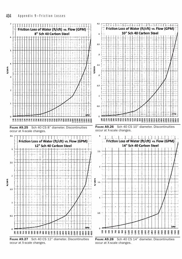
404 A p p e n d i x 9 — F r i c t i o n L o s s e s
FIGURE A9.25 Sch 40 CS 8” diameter. Discontinuities occur at X-scale changes.
FIGURE A9.26 Sch 40 CS 10” diameter. Discontinuities occur at X-scale changes.
FIGURE A9.27 Sch 40 CS 12” diameter. Discontinuities occur at X-scale changes.
FIGURE A9.28 Sch 40 CS 14” diameter. Discontinuities occur at X-scale changes.
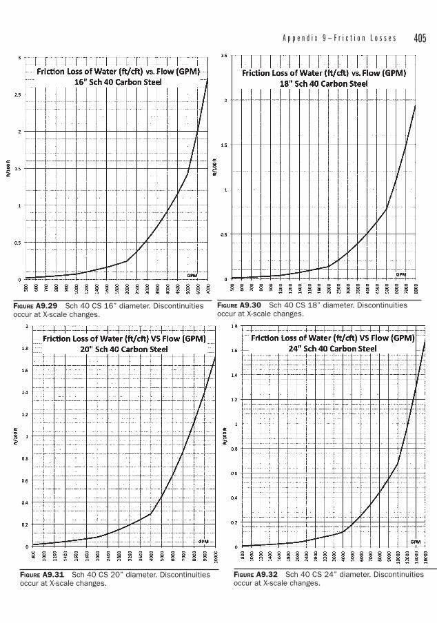
A p p e n d i x 9 — F r i c t i o n L o s s e s 405
FIGURE A9.29 Sch 40 CS 16” diameter. Discontinuities occur at X-scale changes.
FIGURE A9.30 Sch 40 CS 18” diameter. Discontinuities occur at X-scale changes.
FIGURE A9.31 Sch 40 CS 20” diameter. Discontinuities occur at X-scale changes.
FIGURE A9.32 Sch 40 CS 24” diameter. Discontinuities occur at X-scale changes.
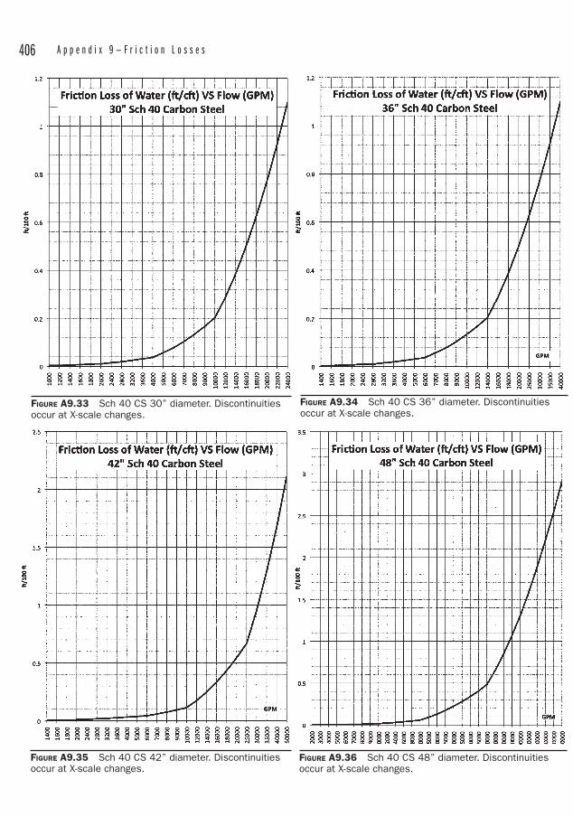
406 A p p e n d i x 9 — F r i c t i o n L o s s e s
FIGURE A9.33 Sch 40 CS 30” diameter. Discontinuities occur at X-scale changes.
FIGURE A9.34 Sch 40 CS 36” diameter. Discontinuities occur at X-scale changes.
FIGURE A9.35 Sch 40 CS 42” diameter. Discontinuities occur at X-scale changes.
FIGURE A9.36 Sch 40 CS 48” diameter. Discontinuities occur at X-scale changes.
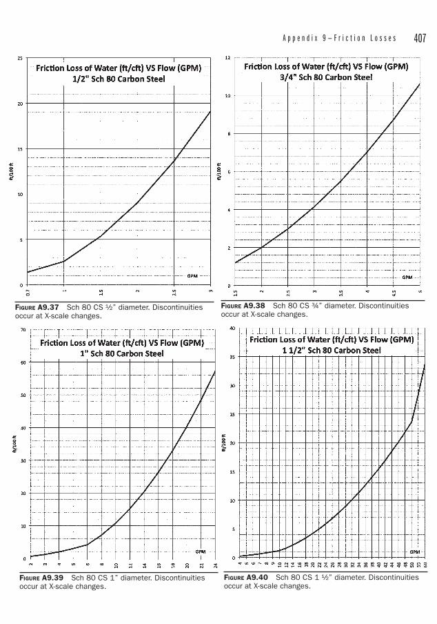
A p p e n d i x 9 — F r i c t i o n L o s s e s 407
FIGURE A9.37 Sch 80 CS ½” diameter. Discontinuities occur at X-scale changes.
FIGURE A9.38 Sch 80 CS ¾” diameter. Discontinuities occur at X-scale changes.
FIGURE A9.39 Sch 80 CS 1” diameter. Discontinuities occur at X-scale changes.
FIGURE A9.40 Sch 80 CS 1 ½” diameter. Discontinuities occur at X-scale changes.
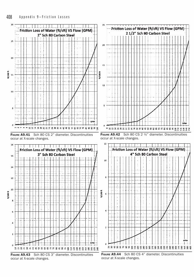
408 A p p e n d i x 9 — F r i c t i o n L o s s e s
FIGURE A9.41 Sch 80 CS 2” diameter. Discontinuities occur at X-scale changes.
FIGURE A9.42 Sch 80 CS 2 ½” diameter. Discontinuities occur at X-scale changes.
FIGURE A9.43 Sch 80 CS 3” diameter. Discontinuities occur at X-scale changes.
FIGURE A9.44 Sch 80 CS 4” diameter. Discontinuities occur at X-scale changes.
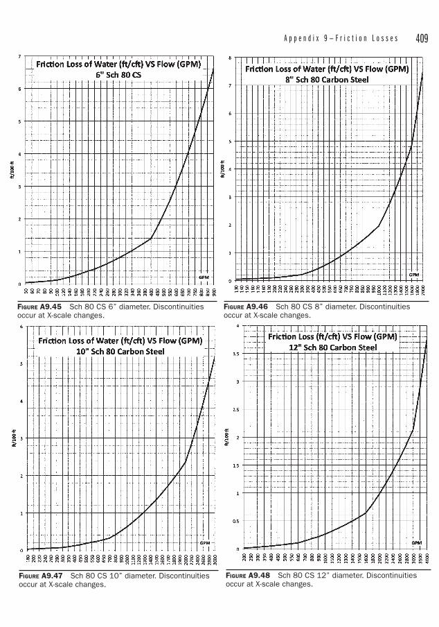
A p p e n d i x 9 — F r i c t i o n L o s s e s 409
FIGURE A9.45 Sch 80 CS 6” diameter. Discontinuities occur at X-scale changes.
FIGURE A9.46 Sch 80 CS 8” diameter. Discontinuities occur at X-scale changes.
FIGURE A9.47 Sch 80 CS 10” diameter. Discontinuities occur at X-scale changes.
FIGURE A9.48 Sch 80 CS 12” diameter. Discontinuities occur at X-scale changes.
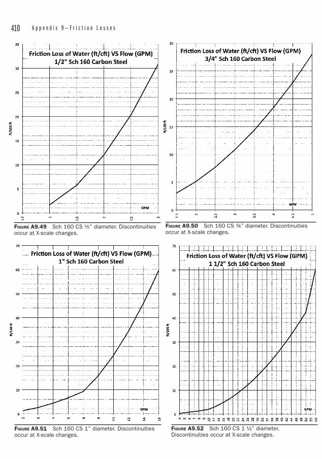
410 A p p e n d i x 9 — F r i c t i o n L o s s e s
FIGURE A9.49 Sch 160 CS ½” diameter. Discontinuities occur at X-scale changes.
FIGURE A9.50 Sch 160 CS ¾” diameter. Discontinuities occur at X-scale changes.
FIGURE A9.52 Sch 160 CS 1 ½” diameter. Discontinuities occur at X-scale changes.
FIGURE A9.51 Sch 160 CS 1” diameter. Discontinuities occur at X-scale changes.
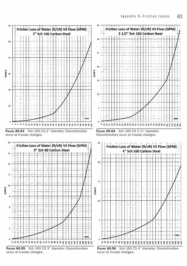
A p p e n d i x 9 — F r i c t i o n L o s s e s 411
FIGURE A9.53 Sch 160 CS 2” diameter. Discontinuities occur at X-scale changes.
FIGURE A9.54 Sch 160 CS 2 ½” diameter. Discontinuities occur at X-scale changes.
FIGURE A9.55 Sch 160 CS 3” diameter. Discontinuities occur at X-scale changes.
FIGURE A9.56 Sch 160 CS 4” diameter. Discontinuities occur at X-scale changes.
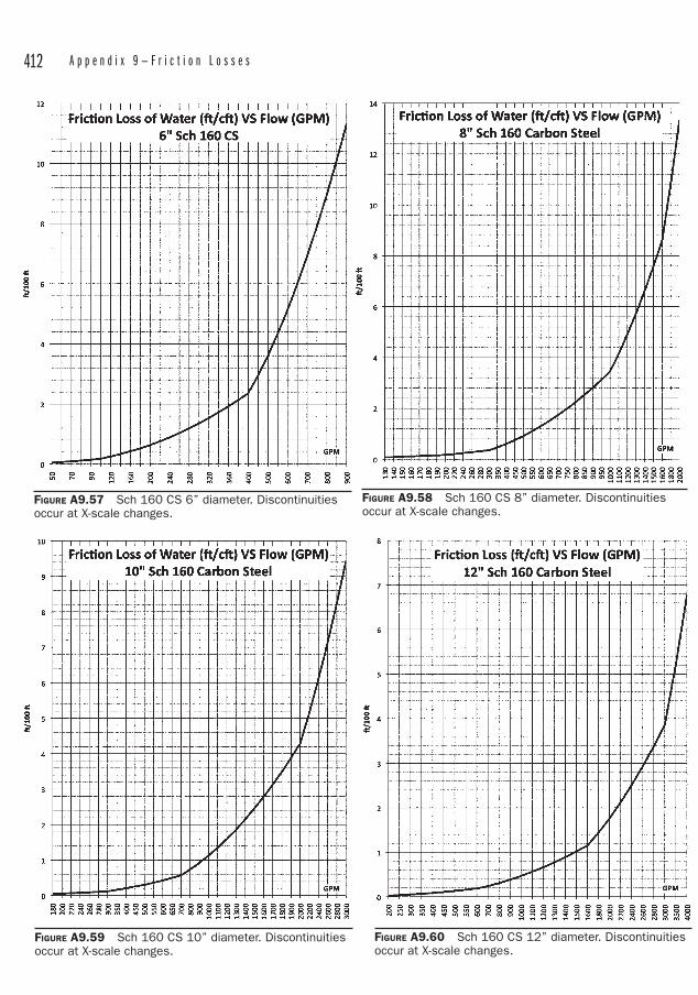
412 A p p e n d i x 9 — F r i c t i o n L o s s e s
FIGURE A9.57 Sch 160 CS 6” diameter. Discontinuities occur at X-scale changes.
FIGURE A9.58 Sch 160 CS 8” diameter. Discontinuities occur at X-scale changes.
FIGURE A9.60 Sch 160 CS 12” diameter. Discontinuities occur at X-scale changes.
FIGURE A9.59 Sch 160 CS 10” diameter. Discontinuities occur at X-scale changes.

413
Index
AABS, 84, 118, 132–133absolute temperature, 262 viscosity, 272acoustical leak detectors, 356actuator, 3air break, 3air gap, 3angle of repose, 3anchor, 230–232, 240–242, 250angle of repose, 258, 357Annubar®, 218ANSI flanges, 165API flanges, 165asbestos, 167asbestos cement pipe, 139ASCE 7, Minimum Design
Loads for Buildings and Other Structures, 242
ASHRAE 90.1, 265, 288ASME Boiler and Pressure
Vessel Code, 196, 198, 201ASME Code for Pressure
Piping, B31, 20aspirate, 183ASSE 1016, 212ASSE 1017, 212ASSE 1066, 212ASSE 1070, 212ASSE Valves, 211austenitic, 97, 104–105authority having jurisdiction, 3,
306–307autogenous healing, 357
Bbackflow preventers, 208bacteria, 363ball valves, 4, 190Barlow's formula, 24, 93baseplate, 4bearing lube oil, 333Bélier, 362bell and spigot, 86–88, 96, 137
bentonite, 359Bernoulli's equation, 262bid tabulation, 4, 321biofilms, 341–342blind, 4blind flanges, 164block-and-bleed, 4block flow diagrams, 301blowdown, 199boiler external piping, 4, 22, 53boiling, 363bolting, 158, 168–169bolt torques, 169BOP, 257bore size, 190borosilicate, 83branch connections, 25, 42brazing, 112bubble-tight, 206building codes, 306bumping, 333Buna-N, 145bushings, 174butterfly valves, 192, 194
CC-factor, 279CAD standards, 307calcium Silicate, 146caps, 149, 180car-seal, 192cast, 84–88, 92–93, 95–96, 109,
113, 134, 139casting factor, 23cast iron pipe, 85–86 threaded fittings, 173Category D fluids, 39Category M fluids, 39cathodic protection, 166cavitation, 183, 194, 265, 290,
293–294cellular glass, 147cement mortar lining, 357CGA G-4.4, 351checklists, 310–311
check valves, 187–189chlorine, 363chlorine dioxide, 363–364clack valve, 362cleanouts, 149, 172Clean Water Act of 1977, 360clearances, 258close-by-close, 178coal tar epoxy, 95Code 61, 166Code 62, 166coldwell, 303Colebrook equation, 272,
277–278Colorado River, 360combined storm and sewer, 356composites, 84, 144compressed air, 335, 349, 352concrete pipe, 137–138condensation, 339contractor, 245, 250, 260control valve, 183, 194–195, 198,
207cooling towers, 341copper-silver ionization, 341corrosion allowance, 23–24, 30,
45cotton ball test, 345couplings, 180coupons, 337CPVC, 84, 117, 122–123critical path, 308cross connection, 5crosses, 149, 178cryptosporidia, 364CSI format, 321cured-in-place pipe, 357Cuyahoga River, 360Cv, 282–283
DDarcy friction factor, 272, 280Darcy Weisbach equation, 271DBOO, 5degrees-of-freedom, 223deionized water, 226

414 I n d e x
descale, 353design basis, 306–307Design Institute for Emergency
Relief Systems, 202design life, 356diaphragm valves, 207dielectric connections, 166DIERS, 202dimension ratio, 128dirt leg, 5, 347disinfection, 364diversity factors, 298document control, 311, 345double-containment, 131drawing sizes, 246ductile iron pipe, 85, 92, 95DWV (drain, waste, and vent),
6, 85dynamic analysis, 242 viscosity, 272
Eearthquakes, 338elbows, 149, 151, 169, 171electrical gear, 329electrofusion sleeve, 130elevation head, 264emergency shower, 38environmental loads, 306EPDM (ethylene prophlene diene
monomer), 146escutcheon, 5equipment lists, 309 specifications, 316equivalent length, 271–272,
280–281, 289excess pipe wall, 27–28, 30–32, 48expansion joints, 219, 220explosion, 355extrados, 5extruded outlets, 26eyewash station, 38
Ffabricated fitting, 25Fanning friction factor, 271, 280fast track, 261ferritic, 97, 104–105fiberglass, 136–137, 146field-routed, 245, 260field engineering, 312 routed, 260 trim, 305filtration, 363
finite element analysis, 240fires, 337fire loop, 7fitness for service, 30flange ratings, 152flat-on-bottom, 226flat faced, 158flexibility, 35, 51, 54flood, 337flood level rim, 7flow coefficient, 282Flow Maps, 308flow meters, 217–219fluid velocities, 194fluoropolymer, 146flushing, 332flux, 112foot valves, 190forged, 84, 109freeze protection, 343friction losses, 265FRP (fiberglass reinforced plastic),
84, 136–137, 145furnace butt weld, 50fusion welding, 130
Ggas constant, 262–263gaskets, 138, 151–152, 166–167gasket thickness, 306gate valves, 184Gaviotas, Colombia, 362general arrangement, 307 notes, 305germicidal, 364giardia,, 364globe valves, 186–187GPS unit, 361gray cast iron, 85greenfield, 7guinea worm disease, 363
HHaaland equation, 272, 277hazardous area classifications, 307Hazen Williams formula, 271HAZOP (hazard and operability
ananysis), 7HDPE (high-density polyethylene
piping), 84, 124–126, 131, 135, 361–362
high point vents, 334high pressure fluids, 40, 50hollow structural sections, 226hoses, 219hot water systems, 341
HPBV (high-performance butterfly valves), 194
HSS (hollow structural sections), 226
hubless, 85–87huddling chamber, 198hydraulic diameter, 271–272 oil, 333 radius, 280 ram pump, 362 systems, 353hydrogen, 353hydronic, 8hydrostatic design basis, 129 stress, 42, 129hydrotest, 38, 337hyperchlorination, 341
Iindirect connection, 8infrared imaging, 356infrastructure, 355instrument air, 350insulating materials, 146intent to bid, 320interferences, 345International Code Council, 18International Fuel Gas Code, 174intrados, 8invert elevations, 8, 257iodine, 363–364ISA 7.0.01, 350isometrics, 309
KK, 262, 280–281, 283, 291kinematic viscosity, 272, 278Kynar®, 145
Llaminar flow, 276lap joint flanges, 162, 164laterals, 149, 172lead wool, 87leadite, 87leakage, 96, 349, 354leak detection and repair, 203leaks, 359Legionella, 341–342limit stops, 331line number, 303lined piping, 145linework, 250load cases, 243

I n d e x 415
loop number, 305lug-type, 192
MMach number, 262magmeters, 219major losses, 265, 271malleable iron fittings, 173manufactured fitting, 25markers, 357martensitic, 104match marking, 320material take-off, 309maximum allowable stress, 23,
30, 53maximum allowable working
pressure, 8MCC, 329mechanical joints, 96methane, 347mill tolerance, 23, 28–31, 40–41,
47–48mineral wool, 147minor losses, 265, 280monochloramine, 342Montgolfier, 362Moody Diagram, 272,
275–277, 279
NN+1, 289, 350NASA NAS 1638, 353National Electric Code, 258natural gas, 347–348, 352needle valves, 194Neoprene®, 146nipples, 178nitrile, 145nominal diameter, 84, 101–102non-fragmenting, 203non-rising stem, 185normal fluids, 40, 50north arrow, 257nozzle weld, 171
OO-Let®, 180oakum, 86odorant, 347one call, 339, 357operator error, 342order of precedence of
documents, 322orifice flanges, 151, 164 plates, 217–218
oxy-fuel cutting, 351oxygen, 350–352
PP&ID, 9, 246, 301, 303parasites, 363passivation, 332PEEK (polyetheretherketone), 146PEX (cross-linked polyethylene
piping), 84, 133–135, 144PFD (process flow diagram), 9phthalates, 116pig, 354pigging, 226pilot-operated valves, 199pipe bursting, 358 cleanliness, 332 ramming, 359 supports, 221plugs, 149, 151–152, 180plug valves, 207pneumatic test, 37polybutylene, 124polychloroprene, 146polyethylene, 85, 92, 124–128,
133–135polyisocyanurate, 147polymer mortar pipe, 144polystyrene, 148power-control valve, 198power piping, 20–21prefabbed pipe spools, 346pressure and temperature
variations, 40pressure classes, 152, 158 head, 264 regulating valves, 195 relief valves, 9, 196 tests, 37 transmitters, 217process piping, 19, 39–40protazoa, 363PTFE (polytetrafluoroethylene),
145pumps, 333pup, 17purging, 349PVC (polyvinyl cloride piping),
83–84, 88, 116–120, 122–123, 133PVDF (polyvinylidene fluoride),
145
Qquarter-turn, 190, 192, 207quad-stenciled, 100
Rrack piping, 224, 258raised face flanges, 158ratio of specific heats, 262reduced pressure principle, 209reducers, 149, 173–175, 180, 226,
239, 257, 281rehabilitation, 356–357rehearsing, 168reinforcement zone, 27reinforcing pad, 28relief valve, 10, 196–198reservoirs, 332resistance coefficient, 280–281Reynolds number, 275–276RFID, 340, 357rising stem, 185rods, 222, 232rolling offsets, 171roughness, 265, 271, 275rupture disks, 10, 202, 205
SSAE AS4059, 353SAE flanges, 166SAE J518, 152safeguarding, 10, 51safety, 329, 331safety plan, 330 relief valve, 10 valve, 10, 197–198salt water contamination, 337scalding, 211–212scales, 247schedule, 84, 101–102, 109, 147scope of supply, 250screwed flanges, 164seal welded, 164seats, 184–187, 191–192, 205–206,
213–214seismic reactions, 242Serghide's Solution, 272, 278shoes, 228–229, 233SIF, 240signage, 343silver solder, 112skid-mounted, 320sleeper, 11slip-on flange, 161sliplining, 358–359smoke and dye detection, 356snubbers, 222, 241socket weld flanges, 161sodium hypochlorite, 363–364soil pipe, 6, 85soil stack, 11

416 I n d e x
solar disinfection, 366 panels, 362 powered pumps, 361solvent cementing, 130Sovent®, 85spacing, 258spec break, 323specialty, 11spool, 11stack, 11standard temperature
and pressure, 283static discharge head, 286static electricity, 136static suction lift, 286steam systems, 334steam traps, 212Stellite®, 184strainers, 216stress analysis, 221, 240 intensification factors, 179 range reduction factors, 22struts, 222stub ends, 161–162, 163–164studding outlets, 166suction head, 285–286, 287, 294suction lift, 286–287, 294support spacing, 226swaged nipples, 152, 180Swamee-Jain equation, 272, 278synthetic rubber, 147
TT&P, 202TAFR valves, 212take-out, 12, 149, 170–171, 179tees, 149, 171–172Teflon® tape, 348
temperature elements, 217terra cotta, 83test gag, 201–202, 331thermal expansion, 224thermal growth, 339thermal shock, 211–212thermofusion sleeves, 362thickness class, 84thrust block, 91–92tie points, 260TIG weld, 332, 351transition zone, 276trapezes, 231travel stops, 334trenches, 258trenchless technologies, 357trim, 12, 184triple-duty valves, 207tri-stenciled, 100tubing, 84, 106, 109, 115–116,
125–127, 134–135turbulent flow, 276turn down, 305
UU-bends, 179U-bolts, 225ultrasonic, 219, 354ultraviolet radiation, 342, 366umbrella fitting, 201underground markers, 340uniform loads, 242unions, 149, 151, 178Universal Gas Constant, 263US Clean Air Act, 203USS Sultana, 18utility consumption, 298,
307–308utility distribution diagrams,
308
utility drop, 352 headers, 224 quality, 300
VV-port ball valve, 190vacuum breakers, 208–209valve leakage, 205Van Stone flanges, 162variable frequency drive, 183,
303, 359velocity head, 264VFD, 359viruses, 363
Wwafer-type, 192walkdown, 331wall head adapter, 348wall thickness, 84, 91, 93, 95,
98, 100–102, 109, 119, 128–129, 133, 137
warm-up jumpers, 335water-borne diseases, 363water conservation, 360 hammer, 265, 356, 359 heaters, 202 restrictions, 360weight, 84welding symbols, 255weld joint efficiency, 23weld neck flanges, 160–161wet insulation, 337wet vent, 13witches hats, 333wood stave, 83working space, 258wrought, 84, 109, 113wyes, 149, 180


