1767 Korean J. Chem. Eng., 33(6), 1767-1776 (2016) DOI: 10.1007/s11814-016-0074-x REVIEW PAPER pISSN: 0256-1115 eISSN: 1975-7220 INVITED REVIEW PAPER † To whom correspondence should be addressed. E-mail: [email protected]‡ These authors contributed equally to this work. Copyright by The Korean Institute of Chemical Engineers. Dynamic modeling and simulation of reaction, slag behavior, and heat transfer to water-cooling wall of shell entrained-flow gasifier Cheol-Oong Kim * ,‡ , Ryang-Gyoon Kim ** ,‡ , Zelin Wu *** , and Chung-Hwan Jeon *** ,† *Senior Researcher, Energy Technology Team, GS Engineering & Construction Co., Ltd., Seoul 03159, Korea **Senior Researcher, PosCC (Clean Coal), Research Institute of Industrial Science & Technology, Pohang 37673, Korea ***School of Mechanical Engineering, Pusan Clean Coal Center, Pusan National University, Busan 46241, Korea (Received 9 August 2015 • accepted 6 March 2016) Abstract-A mathematical model is developed to simulate a pilot Shell entrained-flow coal gasifier. Submodels of spe- cific structures of the gasifier are established to simulate the complicated gasification process. The model includes the total energy conservation equation and mass conservation equations for the gas components, solid flow, and gas flow. It simulates the influence of the gasifier structure and dimensions and can calculate the effects of changing almost every important operation parameter, e.g., the syngas composition, gasification temperature, carbon conversion ratio, wall- layer temperature, and slag mass flow rate. The model can predict the syngas composition under a limited residence time condition. Furthermore, it considers the heat transfer coefficient of each layer of the water wall to calculate its heat loss and temperature. Thus, the model also reflects the influence of performance parameters of the gasifier’s water wall. The slag mass flow rate on the wall is calculated using a slag submodel. Keywords: Entrained-flow Gasifier, Dynamic Modelling, Simulation, Reaction, Water Wall Heat Transfer, Slag Behavior INTRODUCTION One commercial plant project in South Korea employs the coal gasification technology. A 300-MW-class Integrated Gasification Combined Cycle (IGCC) plant based on the Shell gasifier is being constructed by Korea Western Power, a power plant company. In parallel, various design technology developments of a gasification block of the plant, such as reviewing the effect of operation fac- tors on the gasifier, have also been progressing [1]. The IGCC is a coal gasification technology, coal gas purification technology, and high-performance combined gas turbine and steam turbine cycle technology; it further involves the process integration. The IGCC also differs from the conventional gas-steam combined cycle mainly in terms of the coal gasification and purification systems and equipment [2-5]. Therefore, research aimed at the development of large-capacity and high-energy-conversion-efficiency coal gasifiers is the key to achieving an IGCC power generation scheme. Several models for studying the gasification process in the gas- ifier have been established [6-8]; in particular, entrained-flow gasifi- ers have been the object of extensive research. Some early research considered a stable state in the gasification process in order to ana- lyze the influence of different operating conditions on the gasifier performance. For instance, Wen developed a mathematical model for simulating the Texaco pilot-plant down-flow entrained gasifier [6]. Govind simulated the Texaco pilot-plant down-flow gasifier by simultaneously solving the mass, momentum, and energy balance equations for the solid and gas phases [9]. Matteo conducted sim- ulation studies using the Aspen Plus software for the Shell gasifier IGCC system to determine the water-wall temperature, the compo- sition and temperature of the gasifier outlet gas, and a rule for de- termining changes in the gasifier performance so as to build a foun- dation for further research on IGCC performance [10]. Sun devel- oped a dynamic model of the Shell gasifier IGCC system on the basis of physical principles, by focusing on the time-dependent ac- cumulation and flow on the walls [11,12]. These studies on the per- formance of entrained-flow gasifiers have provided crucial knowl- edge on the gasification process. At present, two types of methods are available for modeling the gasification process in the gasifier. One is thermodynamic model- ing. In this modeling, according to the laws of thermodynamics, the mass balance equation for different materials and the energy bal- ance equation are formulated, and then, the equilibrium gasifica- tion temperature and gas composition are estimated under given operating conditions. This permits estimation of the influence of the gasifier size on the gasification process. The other type of method is dynamic modeling in which the dynamics of the main chemi- cal reactions in the gasifier are considered along with the gasifier structure and operating conditions. Then, the gas component tem- perature and coal conversion ratio are forecast, and finally, the gas- ifier performance is evaluated accordingly. In the present work, a dynamic model of the gasification performance of the Shell coal gasifier is proposed. The proposed mathematical model considers in detail the gas and solid flow processes as well as the combustion reaction and the dynamic water-gas reaction process. The model not only estimates the influence of the gasifier structure size but also calculates the main gasifier performance parameters. The structure of the Shell
Transcript
1767
Korean J. Chem. Eng., 33(6), 1767-1776 (2016)DOI: 10.1007/s11814-016-0074-x
REVIEW PAPER
pISSN: 0256-1115eISSN: 1975-7220
INVITED REVIEW PAPER
†To whom correspondence should be addressed.E-mail: [email protected]‡These authors contributed equally to this work.Copyright by The Korean Institute of Chemical Engineers.
Dynamic modeling and simulation of reaction, slag behavior, and heat transferto water-cooling wall of shell entrained-flow gasifier
Cheol-Oong Kim*,‡, Ryang-Gyoon Kim**
,‡, Zelin Wu***, and Chung-Hwan Jeon***,†
*Senior Researcher, Energy Technology Team, GS Engineering & Construction Co., Ltd., Seoul 03159, Korea**Senior Researcher, PosCC (Clean Coal), Research Institute of Industrial Science & Technology, Pohang 37673, Korea
***School of Mechanical Engineering, Pusan Clean Coal Center, Pusan National University, Busan 46241, Korea(Received 9 August 2015 • accepted 6 March 2016)
Abstract−A mathematical model is developed to simulate a pilot Shell entrained-flow coal gasifier. Submodels of spe-cific structures of the gasifier are established to simulate the complicated gasification process. The model includes thetotal energy conservation equation and mass conservation equations for the gas components, solid flow, and gas flow. Itsimulates the influence of the gasifier structure and dimensions and can calculate the effects of changing almost everyimportant operation parameter, e.g., the syngas composition, gasification temperature, carbon conversion ratio, wall-layer temperature, and slag mass flow rate. The model can predict the syngas composition under a limited residencetime condition. Furthermore, it considers the heat transfer coefficient of each layer of the water wall to calculate its heatloss and temperature. Thus, the model also reflects the influence of performance parameters of the gasifier’s water wall.The slag mass flow rate on the wall is calculated using a slag submodel.
One commercial plant project in South Korea employs the coalgasification technology. A 300-MW-class Integrated GasificationCombined Cycle (IGCC) plant based on the Shell gasifier is beingconstructed by Korea Western Power, a power plant company. Inparallel, various design technology developments of a gasificationblock of the plant, such as reviewing the effect of operation fac-tors on the gasifier, have also been progressing [1]. The IGCC is acoal gasification technology, coal gas purification technology, andhigh-performance combined gas turbine and steam turbine cycletechnology; it further involves the process integration. The IGCCalso differs from the conventional gas-steam combined cycle mainlyin terms of the coal gasification and purification systems andequipment [2-5]. Therefore, research aimed at the development oflarge-capacity and high-energy-conversion-efficiency coal gasifiersis the key to achieving an IGCC power generation scheme.
Several models for studying the gasification process in the gas-ifier have been established [6-8]; in particular, entrained-flow gasifi-ers have been the object of extensive research. Some early researchconsidered a stable state in the gasification process in order to ana-lyze the influence of different operating conditions on the gasifierperformance. For instance, Wen developed a mathematical modelfor simulating the Texaco pilot-plant down-flow entrained gasifier[6]. Govind simulated the Texaco pilot-plant down-flow gasifier bysimultaneously solving the mass, momentum, and energy balance
equations for the solid and gas phases [9]. Matteo conducted sim-ulation studies using the Aspen Plus software for the Shell gasifierIGCC system to determine the water-wall temperature, the compo-sition and temperature of the gasifier outlet gas, and a rule for de-termining changes in the gasifier performance so as to build a foun-dation for further research on IGCC performance [10]. Sun devel-oped a dynamic model of the Shell gasifier IGCC system on thebasis of physical principles, by focusing on the time-dependent ac-cumulation and flow on the walls [11,12]. These studies on the per-formance of entrained-flow gasifiers have provided crucial knowl-edge on the gasification process.
At present, two types of methods are available for modeling thegasification process in the gasifier. One is thermodynamic model-ing. In this modeling, according to the laws of thermodynamics, themass balance equation for different materials and the energy bal-ance equation are formulated, and then, the equilibrium gasifica-tion temperature and gas composition are estimated under givenoperating conditions. This permits estimation of the influence of thegasifier size on the gasification process. The other type of methodis dynamic modeling in which the dynamics of the main chemi-cal reactions in the gasifier are considered along with the gasifierstructure and operating conditions. Then, the gas component tem-perature and coal conversion ratio are forecast, and finally, the gas-ifier performance is evaluated accordingly. In the present work, adynamic model of the gasification performance of the Shell coalgasifier is proposed.
The proposed mathematical model considers in detail the gasand solid flow processes as well as the combustion reaction and thedynamic water-gas reaction process. The model not only estimatesthe influence of the gasifier structure size but also calculates themain gasifier performance parameters. The structure of the Shell
1768 C.-O. Kim et al.
June, 2016
gasifier includes a number of water tubes around the gasifier itself.Therefore, the proposed model considers the temperature differ-ence between the inside and outside of the gasifier and uses theheat transfer coefficient of each layer of the gasifier wall to calcu-late its heat loss and temperature, and to thus determine the influ-ence of the water-wall performance parameters. A layer of refractorymaterial is applied to the inside of the wall, where high-tempera-ture molten slag flows and where it can ultimately cool and solid-ify to stick to the wall. The resulting mixed slag layer is considerednormal during operation of the gasifier. Therefore, this study alsofocuses on the mass flow rate of the slag layer.
GASIFICATION PROCESS
Gasification processes are classified according to the method usedto bring the coal into contact with the gasifying medium (air oroxygen). The three main commercial modes are the fixed-bed, flu-idized-bed, and entrained-flow-bed modes. This study focuses onan entrained-flow gasifier. In an entrained-flow reactor, small con-densed particles (in the solid or slurry state) are dispersed and en-trained in a moving gaseous medium. This provides a larger sur-face contact area for a reaction, and it can induce a reduction inthe gas-solid diffusion resistance to enable a rapid chemical reac-tion between the solid and gas phases. Furthermore, the particlescan be entrained in the gasifying medium itself to react in a co-current flow in a high-temperature flame. The residence time inthis type of gasifier is extremely short. Entrained-flow gasifiers gen-erally use oxygen as the oxidant and operate at high temperatures,which are well above ash-slagging conditions, to ensure high car-bon conversion ratio.
MODELING ASSUMPTIONS
A one-dimensional model of the reactor system is constructed.The following are the basic assumptions made for constructing themodel.
(1) The solid and gas phases are assumed to be completely mixed.The nature of mixing between these phases can have a significanteffect on the final carbon conversion ratio and product composition.
(2) The system is assumed to be highly dilute, and so, interac-tions among particles can be neglected. A slag layer is assumed toremain on the particle surface.
(3) The ideal gas equation of state is assumed to hold.(4) The temperature is assumed to be uniform throughout the
solid particles.(5) Ash is assumed to be inert and to remain with the particles.
The effect of ash as a catalyst is formally neglected, although thiseffect may have been accounted for indirectly during the establish-ment of the kinetic equations.
(6) Particle attrition is considered not to occur.(7) Because of the high temperature in the reactor, the poten-
tial and kinetic energies are neglected in comparison to the ther-mal energy.
(8) The slag layer is in the liquid state.
EQUATIONS
In the proposed model, the mass, energy, and momentum con-servation equations are considered to vary only along the axis of divi-sion within the reactor, and the gas and solid phases are treated aspseudo-fluids. The conservation equations presented in Table 1 are
Table 1. Conservation equationsConservation Equation VariableGas-phase species Ci gas-phase concentration
Solid-phase species mass ρcoal-af density of ash-free coal
Dynamic modeling and simulation of reaction, slag behavior, and heat transfer to water-cooling wall of shell entrained-flow gasifier 1769
Korean J. Chem. Eng.(Vol. 33, No. 6)
one-dimensional in the axial direction; they are treated as dynamicequations in the model, even for steady-state simulations.
SUBMODELS
1. DevolatilizationIn the gasifier, the temperature is typically higher than 1,300 K.
Therefore, devolatilization occurs because of a rapid temperatureincrease, and moisture evaporates completely when material entersthe reactor. When coal is fed into the gasifier, it first undergoes pyrol-ysis and decomposes into volatile matter and char, as expressed byEq. (1):
The volatile composition and yield are modeled using the Mer-rick model [12]. The final limitation on devolatilization is the rela-tion between the actual volatile yield and the initial volatile matter(vm) content obtained by proximate analysis:
Yvm=Xvm, 0−0.36X2vm, 0 (2)
Devolatilization of gas-phase species is expressed asRdev, i=εpXdafXdev, iρs/tdev (3)
The total volatile matter is given as
(4)
2. Homogeneous ReactionsRate expressions of homogeneous reactions are of the form Rhet=
khet[χa]a[χb]b, and the unit for the rate is kmol/m3/s. The homoge-neous reaction rate expressions considered in the proposed modelare presented in Table 2. The global kinetics of the homogeneousreactions for major species are modeled using the rate expressionsderived by Jones and Lindstedt [13] and Westbrook and Dryer[14]. The equilibrium coefficients for homogeneous reactions aretaken from the NIST-JANAF Thermochemical Tables [15]. For anirreversible homogeneous reaction, the value of khet is calculated overthe expected temperature range inside the gasifier.3. Heterogeneous Reactions
The model considers four heterogeneous reactions as expressed
below:
(5)
(6)
(7)
(8)
For the char oxidation reaction, a mechanism factor φ is used toaccount for direct conversion of carbon to carbon dioxide at lowtemperatures [16]. This factor is estimated according to the methoddescribed in Table 3.
Heterogeneous reaction kinetics is modeled using n-order rateexpressions. Kinetic data can be input into the model in the formof intrinsic variables. These intrinsic kinetic data are used to calcu-late an intrinsic reaction rate constant for the heterogeneous reac-tion. The heterogeneous rate parameters for coal are listed in Table4. When the intrinsic kinetic data are used, the partial pressure ofeach reactant at the particle surface is determined by calculating itsrate of diffusion through a boundary layer around the particle. The
dev
Rdev, tot = − Rdev, ii∑
CαHβOχNεS + α
φ--- +
β
4--- −
χ
2--- −
3δ4-----
⎝ ⎠⎛ ⎞O2 2α 1−
1φ---
⎝ ⎠⎛ ⎞CO→
+ α2φ--- −1⎝ ⎠⎛ ⎞CO2 +
β − 3δ − 2ε2
------------------------
⎝ ⎠⎛ ⎞H2O + δNH3 + εH2S
CαHβOχNεS + α − β( )H2O αCO + α2φ--- −1⎝ ⎠⎛ ⎞CO2→
+ 2α + β − 2χ − 3δ − 2ε
2-----------------------------------------------
⎝ ⎠⎛ ⎞H2 + δNH3 + εH2S
CαHβOχNεS + αCO2 →
2αCO + β − 2χ − 3δ − 2ε
2------------------------------------
⎝ ⎠⎛ ⎞H2 + δNH3 + εH2S
CαHβOχNεS + 4α − β + 2χ + 3δ + 2ε
2-----------------------------------------------
⎝ ⎠⎛ ⎞H2 →
χH2O + αCH4 + δNH3 + εH2S
Table 2. Rate expressions of homogeneous reactionsReaction Rate expression
Tar + O2 CO + H2 + SO2 + N2k7 R7 =108 Tar[ ] O2[ ]1.25
Table 3. Mechanism factorDp (cm) φ Comment
<0.005
0.005-0.1
>0.1 1.0
2Z + 2Z + 2--------------
Z = CO[ ]CO2[ ]-------------- = 2500e
−6249
T-----------
2Z + 2( ) − Z dp − 0.005( )
0.095------------------------------
Z + 2------------------------------------------------------
1770 C.-O. Kim et al.
June, 2016
rate of this reaction (Eq. (9)) is expressed as
(9)
4. Slag BehaviorSometimes mineral matter in coal can cause slagging problems
during coal combustion, such as when Moolarben coal used infive coal-fired power plants in Korea was blended with low-qual-ity coals and used in boilers [17]. Besides, it is more important topredict slag behavior in such as the Shell entrained-flow gasifier inorder to get suitable operation conditions. The char particles maybe trapped in the slag layer if impinging particles plunge deep intothe layer. For this plunging to occur, the particle inertia needs toovercome viscous and interfacial forces, both of which counteractthe penetration of the impinging particles into the wall slag layer.The driving force on a particle is associated with the normal com-ponent of the impact velocity of the char particle balanced against
the slag viscous forces [18]. If the particles are trapped, the slagmass flow rate is affected by their capture efficiency and reactionrate [19,20]. If, however, they are not trapped, the slag mass flowrate is equal to the minimum flow rate. The slag viscosity is thecriterion for judging whether or not particles are trapped.
(10)
The slag viscosity is evaluated as a function of the slag composi-tion and temperature by using the Urbain model [20]:
μslag=aT exp(103/T)
Rhet = 1+ 6
ηintdpρpSin-------------------------⎝ ⎠
⎛ ⎞ηintSinAint − Eint/RuTp( ) ηexP∞
( )nρpexp
if: rpus 18μρs---->
then: − 1
Acs-------
∂mslag
∂z-------------- = − km
uslag
2rsolid------------
4πrp3
3----------ρs
2πrgasifier
rpug-------------------- +
Aeff
Asolid-----------Rhet
else: mslag.lim = us
d----
4πrp3
3----------ρs
2πrgasifier
rp--------------------
Table 4. Kinetic rate parameters for CSIRO gasifier test coals from Ref. [28]Reaction Parameter Unit CRC358 CRC274 CRC299
Fig. 1. Gasification process and evaluated heat transfer terms.
Dynamic modeling and simulation of reaction, slag behavior, and heat transfer to water-cooling wall of shell entrained-flow gasifier 1771
Korean J. Chem. Eng.(Vol. 33, No. 6)
where (11)− ln a=0.2693b+13.9751
5. Heat TransferTo obtain the heat flux and the temperature profile, the energy
balance equation for each layer of the wall is written, as shown inFig. 1. Both the heat transfer from the gas to the particles and thatfrom the gas to the wall are considered along with the heat trans-fer from the external wall to the atmosphere. The Nusselt numbersfor the gas-to-particle and gas-to-wall convections are calculatedusing the Petukhov equation [21]:
(12)
(13)
The Nusselt number for external convection is calculated usingthe Churchill-Chu equation [22]:
(14)
The radiative heat transfer between particles is modeled usingthe radiation-as-diffusion (RAD) model [23]:
(15)
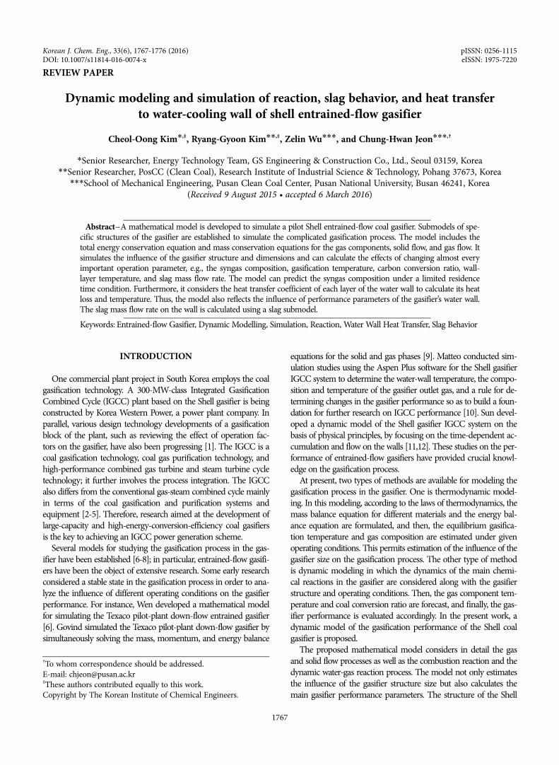
The Shell gasifier is equipped with a water-cooled membrane wall,where intermediate-pressure (IP) steam is produced inside high-pressure steel tubes present all around the reactor jacket. Duringoperation, the solidified ash layer coating the wall acts as the pri-mary thermal barrier [24]. A thin layer of refractory material—generally silicon carbide—is anchored to the tube surface betweenthe steel and the solidified ash to prevent local damage and corro-sion of the membrane wall [25]. Since the membrane wall cannotwithstand a large pressure difference, vessel pressurization is main-tained by means of an outer steel vessel, and an air layer is incor-porated between the outer wall of the gasifier and the membrane
wall [26]. As shown in Fig. 2, the composite wall can be dividedinto six layers: Slag and solid ash layer, silicon carbide (refractory)layer, tube jacket, steam/water mixture, air layer, and steel vesseland ambient air layer. The expressions of the heat transfer termsfor these six layers for use in the energy conservation equationsare as given below.
(16)
At the coolant tubes, heat is conducted across the tube wallsinto the water flowing upward through the tube, which induces aphase change. Determination of the heat transfer coefficient requiresa complex calculation that takes into account the steam-liquid con-ditions at each location in the gasifier. The energy terms obtainedby consideration of a control volume for the determination of thesteam-water fraction are the convective heat flow from the tubeand the enthalpy of the incoming/exiting water mixture [27]. Theexpressions for the coolant tubes are as follows:
The heat transfer coefficient of the mixture is expressed as
(18)
SIMULATION AND METHODOLOGY
The modeling study was conducted using the general PROcessModeling System (gPROMS). In gPROMS, the governing equation,boundary conditions, and initial conditions are necessary for thesimulation. Three types of Australian bituminous coals were usedin these simulations: CRC358 coal, CRC274 coal, and CRC299 coal.The gasifier operating conditions and coal compositions are pre-sented in Table 5, and the schematic diagram of the Shell gasifieris shown in Fig. 11.
RESULTS AND DISCUSSION
1. Syngas CompositionTo demonstrate the validity of the proposed entrained-flow gas-
ifier model, the performance of the Shell gasifier was simulated.Data reported by Shell were used as reference data in the simulation[24]. The simulation results shown in Fig. 3 are close to the refer-ence data. In particular, the exit gas compositions are roughly thesame. The simulated carbon monoxide content is slightly higherthan the reference value, because the conditions used for the modelare slightly different from the actual operating conditions. At theexit, the simulated carbon dioxide content is slightly lower than thereference value.
Fig. 2. Gasifier wall structure and cooling mechanism.(1) Gas (6) Membraneout(2) Slag (7) Air(3) Refractory (8) Steel(4) Membranein (9) Ambient(5) Water
1772 C.-O. Kim et al.
June, 2016
The gas composition inside the gasifier is shown in Fig. 4. Thehorizontal axis represents the residence time of the coal particlesin the gasifier. According to the conservation of momentum, thecoal particles are estimated to remain in the gasifier for at least 4s.Although the particle trajectory is uncertain, for simulating the gascomposition dynamics, the model uses the minimum line distanceto calculate the residence time of the coal particles. When these par-ticles enter the gasifier, the oxygen concentration drops rapidly be-
cause of the subsequent combustion of the volatiles. This processalso reduces the hydrogen concentration rapidly, but it increasesthe carbon dioxide concentration. Then, the carbon dioxide con-centration reduces gradually; this reduction is an indicator of theend of the devolatilization and combustion processes and the begin-ning of the main gasification stage. In the main gasification stage,the carbon monoxide and hydrogen concentrations increase grad-ually. Under the input conditions considered here, this increase
Table 5. Gasifier operating conditions and coal compositionsDimensions of gasifier and membrane wallHeight 10 m Tube diameter 0.2 mInner diameter 3 m Tube thickness 0.006 mSteel vessel thickness 0.06 m Membrane pressure 54 atmTube length 10 m Refractory thickness 0.06Input datePressure 44 atm Coal flow rate 49 kg/sWater pressure 54 atm Air layer 0.6 mParticle diameter 100μm Gas inlet temperature 1373 KOxygen/coal ratio 0.86 Steam/coal ratio 0.038Coal type CRC358 CRC274 CRC299Proximate analysisFixed carbon 59.4% 58% 39.7%Volatile matter 19.2% 28% 24.3%Ash 20.2% 9.3% .025%Moisture 01.2% 4.7% 10.9%Ultimate analysisC 69.6 72 52.1H 03.7 4.1 02.8O 03.3 7.8 08.1N 01.4 1.7 00.8S 00.7 0.4 00.3Ash 20.2 9.3 25.0Moisture 01.2 4.7 10.9
Fig. 3. Comparison of gas concentrations at gasifier outlet. Fig. 4. Gas composition inside the gasifier at various times.
Dynamic modeling and simulation of reaction, slag behavior, and heat transfer to water-cooling wall of shell entrained-flow gasifier 1773
Korean J. Chem. Eng.(Vol. 33, No. 6)
leads to the production of a syngas consisting mainly of carbonmonoxide. The amount of steam, which is the gasification agent,also reduces gradually in the main gasification stage. In the earlystages, the steam concentration does not decrease rapidly. This isbecause the moisture in the coal is first removed in the high-tem-perature devolatilization process and is then consumed in the maingasification stage. Later on in the gasification stage, the gas compo-sition becomes more stable.2. Three Different Temperatures
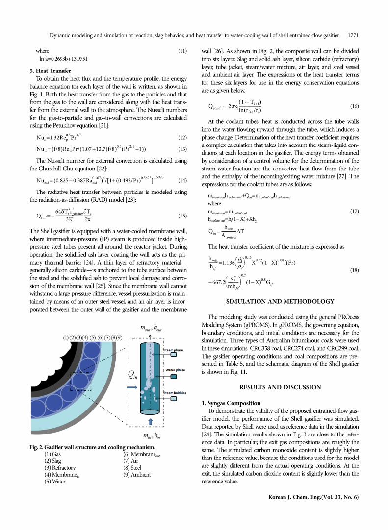
The temperatures of the particles and gas together define the inter-nal temperature of the gasifier. The temperature profiles of the dif-ferent components inside the gasifier are shown in Fig. 5. At theentrance of the gasifier, the particle and gas temperatures increaserapidly because of rapid burning of the volatile components underthe high concentration of oxygen. The particle and gas tempera-tures are obviously different at this location. Analysis of the reac-tion rates suggests that the gas combusts more rapidly and fullythan the particles do. Further along the gasifier, the particle and gastemperatures decrease and eventually remain roughly the same.The computed temperature at the exit is 1,800 K, which is consis-tent with the temperature range provided by Shell. The slag tem-perature at the wall is also shown. The slag temperature is obviouslylower than the temperature inside the gasifier, because of the heattransfer capability of the slag. Nevertheless, the slag temperature isstill inevitably influenced by the internal temperature of the gas-ifier, and it increases and decreases accordingly.
Fig. 6 shows the temperature profile along the gasifier wall. Fromthe slag layer to the water wall, the temperature reduces signifi-cantly, and beyond the water wall, it reduces more gradually. Thistrend meets the design requirements, depending on the tempera-ture difference, while slagging occurs on the refractory layer. Be-cause of the mass flow of water, the internal temperature of thewater wall is radially uniform. The temperature of the outer wallof the gasifier is around 320-340 K, because the thick layer of airpermits only weak radiative heat transfer.3. Slag Viscosity and Mass Flow Rate
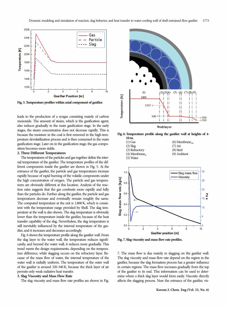
The slag viscosity and mass flow rate profiles are shown in Fig.
7. The mass flow is due mainly to slagging on the gasifier wall.The slag viscosity and mass flow rate depend on the region in thegasifier, because the slag formation process has a greater influencein certain regions. The mass flow increases gradually from the topof the gasifier to its end. This information can be used to deter-mine where a thick slag layer would form easily. Viscosity directlyaffects the slagging process. Near the entrance of the gasifier, vis-
Fig. 6. Temperature profile along the gasifier wall at heights of 4-10 m.(1) Gas (6) Membraneout(2) Slag (7) Air(3) Refractory (8) Steel(4) Membranein (9) Ambient(5) Water
Fig. 7. Slag viscosity and mass flow rate profiles.
Fig. 5. Temperature profiles within axial component of gasifier.
1774 C.-O. Kim et al.
June, 2016
cosity decreases because of the rapid temperature increase. Lowviscosity causes a rapid increase in mass flow. Several factors canaffect viscosity, but from our results, we conclude that tempera-ture is the main factor affecting viscosity in this system.
The slag mass flow rates for two types of coal are shown in Fig. 8.The rates show the same general trends for both the types. Underthe same operating conditions, high-ash coal shows greater massflow. The simulation results are consistent with data acquired fromthe actual process, and in both cases, temperature has a direct effecton the slag mass flow rate.4. Carbon Conversion
Fig. 9 shows the carbon conversion ratios along the gasifier length.The use of coal with higher volatile content and less fixed carboncan greatly improve the gasification conditions. Because of the rapidliberation of volatiles, complete carbon conversion can be achieved.On the other hand, the combustion of volatiles results in the gen-eration of large amounts of heat to promote gasification. Accord-
ing to the simulation results, complete carbon conversion is almosthighest at the front of the gasifier. This seems to be a commonfeature of most commercial entrained-flow gasifiers.5. Coolant Steam Fraction
Fig. 10 shows the effects of the coolant mass flow rate on the steam
Fig. 9. Carbon conversion along the gasifier length for two types ofcoal.
Fig. 11. Schematic diagram of Shell gasifier.
Fig. 8. Slag mass flow rates for two types of coal. Fig. 10. Effect of coolant mass flow rate on steam fraction.
Dynamic modeling and simulation of reaction, slag behavior, and heat transfer to water-cooling wall of shell entrained-flow gasifier 1775
Korean J. Chem. Eng.(Vol. 33, No. 6)
fraction. As mentioned in the discussion of the temperature pro-file along the gasifier wall, no obvious temperature increase occurswithin the water wall despite the transfer of heat from inside thegasifier, because this heat is used up for changing the state of thecoolant. According to the simulation results, increasing the massflow of the coolant can reduce the steam fraction, which is consis-tent with the design requirements. Therefore, a smaller coolant massflow will reduce the cooling effect, and a large coolant mass flowcan make the outlet steam fraction too low and will reduce thetemperature in the gasifier.
CONCLUSIONS
A mathematical model was developed for simulating the per-formance of the Shell entrained-flow gasifier. This model can beused to determine the effects of the gasifier structure and size onits performance, and it includes a description of the kinetics ofevery major chemical reaction occurring in the gasifier. Thus, themodel reflects real responses of materials in the furnace gasifica-tion process to different factors over time and models the actualprocess more closely.
The overall developed model was further refined into submod-els. A model for the mass flow of the slag layer was constructed,and the influence of viscosity and the type of coal on the slag layerbehavior could be modeled using it. Viscosity is a factor directlyaffecting the slag mass flow rate, and because high-temperatureregions have the lowest viscosity, temperature also indirectly affectsthe slagging process. The steam fraction of the water wall is inverselyproportional to the coolant mass flow. In addition to the operat-ing conditions, the model calculates the influence of the type ofcoal on the gasifier performance parameters. Coal with a high vol-atile content helps to efficiently improve the conversion rate, whereascoal with a high ash-carbon content can increase the slag massflow at the gasifier wall.
NOMENCLATURE
A : area [m2]C : gas concentration [kmol/m3]Cp : specific heat capacity [kJ/kg/K]D : diffusivity [m2/s]f : friction factor F : viscous frictional force per unit volume [N/m3]h : enthalpy (kJ/kg) or heat transfer coefficient [kW/m2/K]k : conductivity [kW/m/K]km : bulk-to-wall mass transfer coefficient [s−1]K : equilibrium constant or absorption coefficient [m−1]mw : mole weight [kg/kmol]m : mass flow rate [kg/s]Nu : Nusselt numberP : pressure [atm, MPa, or Pa]Pr : Prandtl numberQ : heat transfer rate per unit axial length [kW/m]r : radius [m]R : rate of chemical reaction [kg/m3/s]Re : Reynolds number
S : swirl numbert : timeT : temperature [K]u : velocity [m/s]X : mass fraction [kg/kg]Y : yield [kg/kg]ϕ : mechanism factorδ : thickness [m]ε : volume fraction [m3/m3]μ : dynamic viscosity [Pa s]ρ : density [kg/m3]
1. H. K. Seo, S. Park, J. Lee, M. Kim, S. W. Chung, J. H. Chung andK. Kim, Korean J. Chem. Eng., 28, 1851 (2011).
2. J. C. Corman, Appl. Energy, 10, 243 (1982).3. J. M. Beer, Prog. Energy Combust. Sci., 26, 301 (2000).4. U. Buskies, Appl. Therm. Eng., 16, 959 (1996).5. X. Chen, M. Y. He, I. Spitsberg, N. A. Fleck, J. W. Hutchinson and
A. G. Evans, Wear, 256, 735 (2004).6. C. X. Chen, M. Horio and T. Kojima, Chem. Eng. Sci., 55, 3861
(2000).7. C. X. Chen, M. Horio and T. Kojima, Chem. Eng. Sci., 55, 3875
(2000).8. X. Z. Sha, Y. G. Chen, J. G. Cao, Y. M. Yang and D. Q. Ren, Fuel,
69, 656 (1990).9. R. Govind and J. Shah, AIChE J., 79, 30 (1984).
10. R. F. D. Monaghan and A. F. Ghoniem, Fuel, 91, 61 (2012).11. B. Sun, Y. W. Liu, X. Chen, Q. Zhou and M. Su, Fuel Process. Tech-
nol., 92, 1418 (2011).12. D. Merrick, Fuel, 62, 534 (1983).13. W. P. Jones and R. P. Lindstedt, Combust. Flame, 73, 233 (1988).14. C. K. Westbrook and F. L. Dryer, Combust. Sci. Technol., 27, 31
(1981).15. M. W. Chase, NIST-JANAF Thermochemical Tables, 4th Ed., National
Institute of Standards and Technology, Gaithersburg, MD (1998).16. C. Y. Wen and T. Z. Chaung, Ind. Eng. Chem. Process. Des. Dev.,
18(4), 684 (1979).17. B. H. Lee, S. I. Kim, S. M. Kim, D. H. Oh, S. Gupta and C. H. Jeon,
Korean J. Chem. Eng., 33, 147 (2016).18. G. N. Shannon, P. L. Rozelle, S. V. Pisupati and S. Sridhar, Fuel Pro-
1776 C.-O. Kim et al.
June, 2016
cess. Technol., 89, 1379 (2008).19. F. Montagnaro and P. Salatino, Combust. Flame, 157, 874 (2010).20. G. Urbain, F. Cambier, M. Deletter and M. R. Anseau, Trans. J.
British Ceram. Soc., 80, 139 (1981).21. F. M. White, Fluid mechanics, 2nd Ed., McGraw-Hill, New York,
NY (1986).22. F. P. Incropera and D. P. DeWitt, Fundamentals of heat and mass
transfer, 5th Ed., Wiley, New York, NY (2002).23. L. D. Smoot and B. W. Brown, Fuel, 66, 1249 (1987).24. M. Gazzani, G. Manzolini, E. Macchi and A. F. Ghoniem, Fuel,
104, 822 (2013).25. J. D. De Graaf, Shell coal gasification technology, Lecture, Tech-
nische Universiteit Eindhoven (2011).26. C. Higman and M. van der Burgt, Gasification, 2nd Ed., Elsevier
Gulf Professional Publishing, Burlington, MA (2008). ISBN: 978-0-7506-8528-3.
27. D. Steiner and J. Taborek, Heat Transfer Eng., 27, 43 (1992).28. Cooperative Research Centre for Coal in Sustainable Develop-


![FLEX FUEL GASIFIER SIMULATION MODEL [FFGSM]mypages.iit.edu/~abbasian/documents/ffgsm_user_manual.pdf · 6) Gasifier Tab: This tab opens the Gasifier Panel where the gasifier input](https://static.documents.pub/doc/80x56/5eb664fad746ec31aa42c957/flex-fuel-gasifier-simulation-model-ffgsm-abbasiandocumentsffgsmusermanualpdf.jpg)


