60
USA A Brand Keeping the World Flowing Piston Actuated Valves
| Date post: | 17-Aug-2019 |
| Category: |
Documents |
| Upload: | nguyenhanh |
| View: | 213 times |
| Download: | 0 times |

USA
A Brand
Keeping the World Flowing
Piston Actuated Valves

Keeping the World Flowing
RELIABILITY IN FLOW CONTROL
CRITICAL APPLICATIONS
RELIABLE OPERATION WHEN IT MATTERS
Assured reliability for critical applications and environments.
Whether used 24/7 or infrequently, Rotork products will operate reliably and efficiently when called upon.
LOW COST OF OWNERSHIP
Long-term reliability prolongs service life.
Rotork helps to reduce long term cost of ownership and provides greater efficiency to process and plant.
QUALITY-DRIVEN GLOBAL MANUFACTURING
Products designed with 60 years of industry and application knowledge.
Research and development across all our facilities ensures cutting edge products are available for every application.
2 Piston Actuated Valves
CUSTOMER-FOCUSED SERVICE WORLDWIDE SUPPORT
Solving customer challenges and developing new solutions.
From initial enquiry through to product installation, long-term after-sales care and Client Support Programmes (CSP).

CORPORATE SOCIAL RESPONSIBILITY
A responsible business leads to being the best business.
We are socially, ethically, environmentally responsible and committed to embedding CSR across all our processes and ways of working.
MARKET LEADER TECHNICAL INNOVATOR
The recognised market leader for 60 years.
Our customers have relied upon Rotork for innovative solutions to safely manage the flow of liquids, gases and powders.
GLOBAL PRESENCE LOCAL SERVICE
Global company with local support.
Manufacturing sites, offices and Centres of Excellence throughout the world provide unrivalled customer services and fast delivery.
Keeping the World Flowing 3
COMPREHENSIVE PRODUCT RANGE SERVING MULTIPLE INDUSTRIES
Improved efficiency, assured safety and environmental protection.
Rotork products and services are used in the Power, Oil & Gas, Water & Wastewater, HVAC, Marine, Mining, Food & Beverage, Pharmaceutical and Chemical industries around the world.
Section PageSection Page
Seal Kits 40
Protection Class and IP Ratings 44
Conversions 45
Corrosion Reference Guide 46
Comparative Charts 47
Opening Speed Chart and Actuator Volume 54
EU Declaration of Conformity 55
Coding Chart 58
Rotork 2
M&M Piston Valves – Features and Benefits 4
M&M Piston Valves – Scheme of Components 5
Valve Selection 6
M&M Piston Actuated Valve Versions 6
Technical Information 7
Product Index 8
Piston Actuated Valves

4 Piston Actuated Valves
Product Index
Backed by Rotork Global Support
M&M Piston Valves – Features and Benefits
Valve body with angle seat design: High flow rate, low pressure drop
Stainless steel valves with universal design: Suitable for vacuum applications
Standard versions with high performing components: Covering a wide range of industrial applications with reduced stock
Standard seal materials as FKM and PTFE: Enhanced compatibility with fluids and resistance at high temperatures
M&M pilot solenoid valves with banjo bolt: User-friendly, quick
Actuator with built-in exhaust filter: Reduced noise, longer life
Bi-Directional version: Waterhammer-free installation for liquid fluids
Wide choice of connections: Screw, weld, flange, clamp connections, spigots
Position indicator: Instantly visible valve position
Actuator housing rotation 360°: Easy and quick installation
Self-registering gland and chevron packing: Longer life
A Brand
Keeping the World Flowing 5
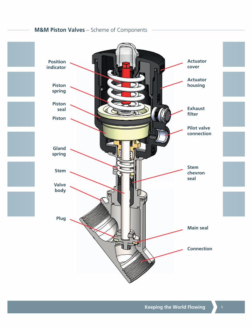
M&M Piston Valves – Scheme of Components
Position indicator
Actuator cover
Actuator housing
Exhaust filter
Pilot valve connection
Stem chevron seal
Connection
Main seal
Plug
Valve body
Gland spring
Stem
Piston
Piston seal
Piston spring

6 Piston Actuated Valves
Piston actuated valves use an external control medium to pilot the actuator, where a piston is directly connected to the main seal that closes onto the main orifice, thereby controlling the flow of liquids and gases.
They are highly recommended under the following conditions:
• Media containing dirt particles
• Highly viscous media (up to 600 cST (80°E) - 1 centistoke = 1 mm²/s)
• High flow volumes
• High temperatures
• Damp environments or hazardous locations
Flow rate values shown in the selection tables are subject to a tolerance of ± 15%.
DOUBLE ACTING Valve – Flow over seat or under seat
The pilot medium opens and closes the valve. No springs. Two 3/2 pilot valves required.
Bi-Directional NC Valve – Flow over seat or under seat
The pressure of the pilot medium opens the valve, the spring closes it. There are two springs and the valve can be used both over seat and under seat.
NC Valve – Flow over seat
The pressure of the pilot medium opens the valve, the spring closes it.
NO Valve – Flow under seat
The pressure of the pilot medium closes the valve, the spring force opens it.
PILOT MEDIUM
PROCESS MEDIUM
PILOT MEDIUM
PROCESS MEDIUM
PILOT MEDIUM
PROCESS MEDIUM
PILOT MEDIUM
Valve Selection
M&M Piston Actuated Valve Versions

Keeping the World Flowing 7
M&M piston actuated valves have been upgraded over the years both by design improvements as well as by using better performing materials. Below you will find some highlights about the outstanding features of M&M piston actuated valves.
Main seal material:
In 2004 virgin PTFE was replaced by a modified PTFE and some design changes in the main seal were introduced. Modified PTFE has a better particle fusion, which gives the following improved features in comparison with PTFE:
• Lower porosity and permeability
• Fewer void spaces
• Higher elasticity
• Reduced deformation under load
• Better chemical resistance to controlled media
• Smoother surface and improved design flexibility
Bonnet chevron packing:
Standard bonnet seals consist of 2 'V'-shaped FKM gaskets and a package of 25% graphite-filled PTFE gaskets.
Stainless steel cast parts:
All our stainless steel series are fitted with bodies and bonnets cast specifically to Norm ASME SA351/351M GRADE CF3M, which is the Alloy Casting Institute designation for cast AISI 316L (normally used for wrought materials).
ACI designation is adopted by many standards issuing organizations, such as ASTM (for instance in ASME B 31.3 for stainless steel castings , appendix B and D, concerning recommended selection of materials for valves manufacturing). Our cast AISI 316L has a content of 10% nickel, which gives improved ductility and strength.
This type of stainless steel can be compared to EN 1.4409 with a good approximation.
All our stainless steel cast parts bear a heat number identifying the basic material composition. Such details are stated in the casting certificate 3.1b, that can be ordered with the valves at an additional fee.
High temperature piston actuated valves:
M&M has developed a piston actuated valve version that can be used up to 392° F (200° C), provided that the valve pressure limits are respected.
The main differences as regards materials and design are the following:
• Change of the actuator material: from standard PA6 to PA66 filled with 30% fibreglass
• All valves with DN > 25 with fixed plug design (to withstand turbulence caused by steam at high speed)
• Special design of bonnet chevrons, all are made of 25% graphite-filled PTFE
Body Pressure (PN) chart and PED classification:
M&M valve bodies bear a PN value which is to be intended as the body design pressure in bar. We use this value as a reference to perform burst tests on the bodies and bonnets upon quality control acceptance. This value is not related to the applicable medium pressure once the valve is in operation. The correct medium pressure is indicated on the valve label and is specific for each valve size and function.
PTFEgraphitefilled 25%
PTFE
Technical Information

8 Piston Actuated Valves
Product Index
Valve Code Type of Connection Actuator Page
BLG - (Bi-Directional) G parallel thread Ø 32 mm 6
CN- (Normally Closed)RCN- (Normally Open)BCN- (Bi-Directional) - NCDCN- (Double Acting)
NPT / G parallel thread Ø 45 mm 7
CN- (Normally Closed)RCN- (Normally Open)BCN- (Bi-Directional) - NCDCN- (Double Acting)
NPT / G parallel thread Ø 63 mmØ 90 mm
8 - 9
Manual OperationCN-
NPT / G parallel thread - 10
Manual OperationPN-
NPT / G parallel thread - 10
PN- (Normally Closed)RPN- (Normally Open)BPN- (Bi-Directional) - NCDPN- (Double Acting)
NPT / G parallel thread Ø 45 mm 11
PN- (Normally Closed)RPN- (Normally Open)BPN- (Bi-Directional) - NCDPN- (Double Acting)
NPT / G parallel thread Ø 63 mmØ 90 mm
12 - 13
PW- (Normally Closed)RPW- (Normally Open)BPW- (Bi-Directional) - NC
BUTT WELD:DIN 11850-2 pipe
Ø 45 mmØ 63 mmØ 90 mm
14 - 15
PD- / PA- (Normally Closed)RPD- / RPA- (Normally Open)BPD- / BPA- (Bi-Directional) - NC
FLANGED:BS 4504 EN1092 shape BANSI B16.5 class 150
Ø 63 mmØ 90 mm
16 - 17
PC- / PP- (Normally Closed)RPC- / RPP- (Normally Open)BPC- / BPP- (Bi-Directional) - NC
CLAMP:ISO 2852ASME BPE
Ø 45 mmØ 63 mmØ 90 mm
18 - 19
High Temperature VersionPN- (Normally Closed)RPN- (Normally Open)BPN- (Bi-Directional) - NC
NPT / G parallel thread / BUTT WELDFLANGED / CLAMP
Ø 63 mmØ 90 mm
20 - 21

Keeping the World Flowing 9
Product Index
Valve Code Type of Connection Actuator Page
PR- (Normally Closed)RPR- (Normally Open)BPR- (Bi-Directional) - NC
THREADED SPIGOTS Ø 45 mmØ 63 mmØ 90 mm
22 - 23
Atex Piston Actuated ValvePN- (Normally Closed)RPN- (Normally Open)BPN- (Bi-Directional) - NC
NPT / G parallel thread Ø 63 mmØ 90 mm
24 - 25
Control Piston Actuated ValveZPN- (flow always under seat)
NPT / G parallel thread Ø 63 mmØ 90 mm
26 - 28
Options/Accessories Code Description Page
E.g. code PN205STWI0 (assembled ex-factory)
Travel Switch Option 29
E.g. code PN205STWR0 (assembled ex-factory)
Stroke Regulator Option 29
85703000-/85703100-/85704000-/85704100-
Position Module 30
85701800- Travel Switch Conversion Kitfor Piston Actuated Valve
31
68000100- / 68000200- Magnetic Switch For Conversion Kit 31
B356CVCW/B326CVCW/ D326CVEW Pilot Solenoid Valves With Banjo Bolt 32 - 35
- Various Part Numbers Seal Kits 36 - 39

10 Piston Actuated Valves
2/2 Way Compact Piston Actuated Valve G 3/8” to 1/2” – Brass
Specifications
Type: BLG NC Bi-directional
flow over/under seat 1 J 2 / 2 J 1
A
P
Media Water, air, inert fluids, inert gases
Media Temperature 14° to 194° F (-10° C to +90° C)
Ambient Temperature 14° to 176° F (-10° C to +80° C)
Pilot Media Filtered air
Actuator Body Material Brass C37700 UNS Designation (CW617N EN12165)
Body Material Brass C37700 UNS Designation (CW617N EN12165)
Piston Material Aluminium
Stem Material Stainless Steel AISI 316L
Main Seal Material NBR
Frequency 6 Cycles per minute
Piston valve with external pneumatic actuation, compact and solid construction.
Suitable for neutral media with particles in suspension, on applications where a standard pilot operated solenoid valve may become clogged.
Features and Benefits
• Waterhammer-free design (with flow direction 2p1)
• Swift installation with banjo bolt pilot solenoid valve B356CVCMK (see pages 32/33)
• Design suitable for vacuum applications up to 8 mTorr (10-2 mbar)
Options Available
Electroless nickel plating treatment (e.g. code BLN205DBW0K)
Dimensions & Weights17/32orifice
(DN13.5)
17/32orifice
(DN13.5)
G connection ISO 228-1 3/8" 1/2"
A in (mm) 2.64 (67) 2.64 (67)
B in (mm) 0.59 (15) 0.59 (15)
C in (mm) 1 (25.5) 1 - 25.5)
D ISO 228-1 1/8" G 1/8" G
E in (mm) 3.31 (84) 3.31 (84)
Weight Lb (kg) 1.21 (0.55) 1.15 (0.52)
Valve PipeSize
OrificeSize
Flow Rate Cv (Kv)
Working PressureMin. Max.
Flow Direction
Pilot PressureMin. Max.
ActuatorØ Function
Code ISO 228G in (mm) gpm (m3/h) psi (bar) psi (bar) — psi (bar) psi (bar) in (mm) —
BLG204DBW00 3/8" 17/32 (13.5) 3.93 / 3.16(3.36 / 2.70) 0 145 (10) 1 J 2 / 2 J 1 65 (4.5) 145 (10)
1.26 (32) NCbidirectionalBLG205DBW00 1/2" 17/32 (13.5) 4.91 / 3.86
(4.20 / 3.30) 0 145 (10) 1 J 2 / 2 J 1 65 (4.5) 145 (10)

Keeping the World Flowing 11
2/2 Way Piston Actuated Valve 1/2 to 1 NPT, Compact Version – Bronze
Options Available
G parallel thread - ISO 228-1 (e.g code CG205CTW00)
Accessories
Position module, travel switch kit, pilot solenoid valves see pages 30/31/32/33
Notes1. Steam max. working pressure 145 psi / 131 psig (10 bar / 9 barg)2. Please contact M&M sales Department for other pilot media3. Minimum pilot pressure at the max. working pressure: for lower working pressures please refer to the comparative charts
Specifications
Type: CN NC flow over seat
1 J 2
A
P
Type: RCN NO flow under seat
2 J 1 P
Type: BCN NC Bi-directional flow
over/under seat1 J 2 / 2 J 1
A
P
Type: DCN DA flow over/under seat
1 Q 2
A
P
Media Water, oil, air, steam1
Media Temperature 14° to 356° F (-10° C to +180° C)
Ambient Temperature 14° to 140° F (-10° C to +60° C)
Pilot Media2 Instrument air, inert gases
Actuator Body Material Polyamide PA6 (reinforced fibreglass 30%)
Body Material Bronze C83600 UNS Designation (CB491K EN1982)
Bonnet Material Brass C37700 UNS Designation (CW617N EN12165)
Main Seal Material PTFE
Position Indicator As standard
Dimensions & Weights DN15 DN20 DN25
Actuator in (mm) Ø 1.77 (45)
A in (mm) 2.56 (65) 2.95 (75) 3.54 (90)
B in (mm) 5.67 (144) 5.87 (149) 6.61 (168)
C in (mm) 5.35 (136) 5.59 (142) 6.34 (161)
D in (mm) 4.84 (123) 4.96 (126) 5.55 (141)
E in (mm) 2.24 (57) 2.24 (57) 2.24 (57)
Weight Lb (kg) 1.76 (0.8) 1.98 (0.9) 2.43 (1.1)
Bodies Group 1 gases
Group 1 liquids andGroup 2 other fluids
19/32 (DN15) to 63/64 (DN25) SEP SEP
The products listed below comply with the requirements of the European Pressure Equipment Directive 2014/68/EU and carry the CE mark when required. The products fall within the following Pressure Equipment Directive categories:
! WARNING!According to the European Pressure Equipment Directive 2014/68/EU, liquids whose saturated vapour pressure at the maximum allowable temperature is more than 7 psi (0,5 barg) shall be considered as gases.
Valve PipeSize
OrificeSize
Flow Rate Cv (Kv)
Working Pressure1 Min. Max.
FlowDirection
Pilot Pressure3
Min. Max.Actuator
Ø Function
Code NPT in (mm) gpm (m3/h) psi (bar) psi (bar) — psi (bar) psi (bar) in (mm) —
CN205CTW00 1/2 19/32 (15) 5.27 (4.50) 0 232 (16) 1 J 2 55 (3.8) 145 (10)
1.77 (45) NCCN206CTX00 3/4 25/32 (20) 9.34 (8) 0 232 (16) 1 J 2 84 (5.8) 145 (10)
CN207CTY00 1 63/64 (25) 14.60 (12.5) 0 232 (16) 1 J 2 94 (6.5) 145 (10)
RCN205CTW00 1/2 19/32 (15) 5.27 (4.50) 0 232 (16) 2 J 1 58 (4) 145 (10)
1.77 (45) NORCN206CTX00 3/4 25/32 (20) 9.34 (8) 0 232 (16) 2 J 1 90 (6.2) 145 (10)
RCN207CTY00 1 63/64 (25) 14.60 (12.5) 0 232 (16) 2 J 1 128 (8.8) 145 (10)
BCN205CTW00 1/2 19/32 (15) 5.27 (4.50) 0 232 (16) /232 (16) 1 J 2 / 2 J 1 90 (6.2) /
73 (5) 145 (10)
1.77 (45) NCbidirectionalBCN206CTX00 3/4 25/32 (20) 9.34 (8) 0 232 (16) /
102 (7) 1 J 2 / 2 J 1 126 (8.7) / 73 (5) 145 (10)
BCN207CTY00 1 63/64 (25) 14.60 (12.5) 0 232 (16) / 73 (5) 1 J 2 / 2 J 1 138 (9.5) /
73 (5) 145 (10)
DCN205CTW00 1/2 19/32 (15) 5.27 (4.50) 0 232 (16) /232 (16) 1 Q 2 44 (3) 145 (10)
1.77 (45) DADCN206CTX00 3/4 25/32 (20) 9.34 (8) 0 232 (16) /232 (16) 1 Q 2 73 (5) 145 (10)
DCN207CTY00 1 63/64 (25) 14.60 (12.5) 0 232 (16) /232 (16) 1 Q 2 123 (8.5) 145 (10)
Features and Benefits
• Waterhammer-free design for BCN - DCN (with flow direction 2p1)
• Actuator housing rotation 360°
• Design suitable for vacuum applications up to 8 mTorr (10-2 mbar)

12 Piston Actuated Valves
Options Available
Stroke regulator assembled ex-factory, see page 29 (e.g. code CN205STWR0)
Travel switch assembled ex-factory, see page 29 (e.g. code RCN209STKI0)
G parallel thread - ISO 228-1 (e.g. code BCG207LTY00)
Design for vacuum applications up to 8 mTorr / 10-2 mbar (e.g. code DCG210STJ0V)
Accessories
Position module, travel switch kit, pilot solenoid valves see pages 30/31/32/33
Specifications
Type: CN NC flow over seat
1 J 2
A
P
Type: RCN NO Flow Under Seat
2 J 1 P
Type: BCN NC Bi-Directional Flow
Over/Under Seat1 J 2 / 2 J 1
A
P
Type: DCN DA Flow Over/Under Seat
1 Q 2
A
P
Media Water, oil, air, steam1
Media Temperature 14° to 356° F (-10° C to +180° C)
Ambient Temperature 14° to 140° F (-10° C to +60° C)
Pilot Media2 Instrument air, inert gases
Actuator Body Material Polyamide PA6 (reinforced fibreglass 30%)
Body Material Bronze C83600 UNS Designation (CB491K EN1982)
Bonnet Material Brass C37700 UNS Designation (CW617N EN12165)
Main Seal Material PTFE
Position Indicator As standard
Dimensions& Weights
19/32(DN15)
25/32(DN20)
63/64(DN25)
1 17/64(DN32)
1 37/64(DN40)
2(DN50)
63/64(DN25)
1 17/64(DN32)
1 37/64(DN40)
2(DN50)
Actuator in (mm) Ø 2.48 (63) Ø 3.54 (90)
A in (mm) 2.56 (65) 2.95 (75) 3.54 (90) 4.33 (110) 4.72 (120) 5.91 (150) 3.54 (90) 4.33 (110) 4.72 (120) 5.91 (150)
B in (mm) 7.56 (192) 7.80 (198) 8.35 (212) 8.86 (225) 9.06 (230) 9.76 (248) 8.78 (223) 9.21 (234) 9.41 (239) 10.12 (257)
C in (mm) 7.24 (184) 7.56 (192) 8.07 (205) 8.54 (217) 8.86 (225) 9.49 (241) 8.50 (216) 8.94 (227) 9.25 (235) 9.84 (250)
D in (mm) 6.73 (171) 6.93 (176) 7.28 (185) 7.60 (193) 7.80 (198) 8.15 (207) 7.72 (196) 7.95 (202) 8.15 (207) 8.50 (216)
E in (mm) 3.35 (85) 3.35 (85) 3.35 (85) 3.35 (85) 3.35 (85) 3.35 (85) 4.41 (112) 4.41 (112) 4.41 (112) 4.41 (112)
Weight Lb (kg) 2.65 (1.2) 2.87 (1.3) 3.31 (1.5) 4.19 (1.9) 4.63 (2.1) 6.39 (2.9) 4.41 (2.0) 5.29 (2.4) 5.73 (2.6) 7.28 (3.3)
The products listed below comply with the requirements of the European Pressure Equipment Directive 2014/68/EU and carry the CE mark when required. The products fall within the following Pressure Equipment Directive categories:
! WARNING!According to the European Pressure Equipment Directive 2014/68/EU, liquids whose saturated vapour pressure at the maximum allowable temperature is more than 7 psi (0,5 barg) shall be considered as gases.
Valve Type Bodies Group 1 gases Group 1 liquids andGroup 2 other fluids
CN - RCN - BCN - DCN
19/32 (DN15) to 63/64 (DN25) SEP SEP
1 17/64 (DN32) to 1 37/64 (DN40) N/A SEP
2 (DN50) N/A SEP
Features and Benefits
• Waterhammer-free design for BCN - DCN (with flow direction 2p1)
• Actuator housing rotation 360°
2/2 Way Piston Actuated Valve 1/2 to 2 NPT, Regular Version – Bronze

Keeping the World Flowing 13
Valve PipeSize
OrificeSize
Flow Rate Cv (Kv)
Working Pressure1
Min. Max.Flow
DirectionPilot Pressure3
Min. Max.Actuator
Ø Function
Code NPT in (mm) gpm (m3/h) psi (bar) psi (bar) — psi (bar) psi (bar) in (mm) —
CN205STW00 1/2 19/32 (15) 6.11 (5.22) 0 290 (20) 1 J 2 54 (3.7) 145 (10)
2.48 (63)
NC
CN206STX00 3/4 25/32 (20) 11.51 (9.84) 0 290 (20) 1 J 2 64 (4.4) 145 (10)
CN207STY00 1 63/64 (25) 18.25 (15.60) 0 290 (20) 1 J 2 73 (5) 145 (10)
CN208STZ00 1 1/4 1 17/64 (32) 28.78 (24.60) 0 232 (16) 1 J 2 86 (5.9) 145 (10)
CN209STK00 1 1/2 1 37/64 (40) 49.14 (42) 0 232 (16) 1 J 2 131 (9) 145 (10)
CN210STJ00 2 2 (50) 66.69 (57) 0 160 (11) 1 J 2 116 (8) 145 (10)
CN207LTY00 1 63/64 (25) 18.25 (15.60) 0 290 (20) 1 J 2 29 (2) 116 (8)
3.54 (90)CN208LTZ00 1 1/4 1 17/64 (32) 28.78 (24.60) 0 232 (16) 1 J 2 51 (3.5) 116 (8)
CN209LTK00 1 1/2 1 37/64 (40) 49.14 (42) 0 232 (16) 1 J 2 58 (4) 116 (8)
CN210LTJ00 2 2 (50) 66.69 (57) 0 218 (15) 1 J 2 94 (6.5) 116 (8)
RCN205STW00 1/2 19/32 (15) 6.11 (5.22) 0 232 (16) 2 J 1 36 (2.5) 145 (10)
2.48 (63)
NO
RCN206STX00 3/4 25/32 (20) 11.51 (9.84) 0 232 (16) 2 J 1 62 (4.3) 145 (10)
RCN207STY00 1 63/64 (25) 18.25 (15.60) 0 232 (16) 2 J 1 80 (5.5) 145 (10)
RCN208STZ00 1 1/4 1 17/64 (32) 28.78 (24.60) 0 232 (16) 2 J 1 94 (6.5) 145 (10)
RCN209STK00 1 1/2 1 37/64 (40) 49.14 (42) 0 232 (16) 2 J 1 131 (9) 145 (10)
RCN210STJ00 2 2 (50) 66.69 (57) 0 174 (12) 2 J 1 136 (9.4) 145 (10)
RCN207LTY00 1 63/64 (25) 18.25 (15.60) 0 232 (16) 2 J 1 29 (2) 116 (8)
3.54 (90)RCN208LTZ00 1 1/4 1 17/64 (32) 28.78 (24.60) 0 232 (16) 2 J 1 58 (4) 116 (8)
RCN209LTK00 1 1/2 1 37/64 (40) 49.14 (42) 0 232 (16) 2 J 1 73 (5) 116 (8)
RCN210LTJ00 2 2 (50) 66.69 (57) 0 232 (16) 2 J 1 102 (7) 116 (8)
BCN205STW00 1/2 19/32 (15) 6.11 (5.22) 0 232 (16) 1 J 2 / 2 J 1 80 (5.5) /55 (3.8) 145 (10)
2.48 (63)
NCbidirectional
BCN206STX00 3/4 25/32 (20) 11.51 (9.84) 0 232 (16) 1 J 2 / 2 J 1 87 (6) /55 (3.8) 145 (10)
BCN207STY00 1 63/64 (25) 18.25 (15.60) 0 232 (16) /160 (11) 1 J 2 / 2 J 1 94 (6.5) /
55 (3.8) 145 (10)
BCN208STZ00 1 1/4 1 17/64 (32) 28.78 (24.60) 0 232 (16) / 87 (6) 1 J 2 / 2 J 1 99 (6.8) /
55 (3.8) 145 (10)
BCN209STK00 1 1/2 1 37/64 (40) 49.14 (42) 0 174 (12) / 58 (4) 1 J 2 / 2 J 1 131 (9) /
55 (3.8) 145 (10)
BCN210STJ00 2 2 (50) 66.69 (57) 0 116 (8) /36 (2.5) 1 J 2 / 2 J 1 131 (9) /
55 (3.8) 145 (10)
BCN207LTY00 1 63/64 (25) 18.25 (15.60) 0 232 (16) /203 (14) 1 J 2 / 2 J 1 58 (4) /
48 (3.3) 116 (8)
3.54 (90)BCN208LTZ00 1 1/4 1 17/64 (32) 28.78 (24.60) 0 232 (16) /
174 (12) 1 J 2 / 2 J 1 73 (5) /48 (3.3) 116 (8)
BCN209LTK00 1 1/2 1 37/64 (40) 49.14 (42) 0 232 (16) / 116 (8) 1 J 2 / 2 J 1 87 (6) /
48 (3.3) 116 (8)
BCN210LTJ00 2 2 (50) 66.69 (57) 0 203 (14) / 87 (6) 1 J 2 / 2 J 1 116 (8) /
48 (3.3) 116 (8)
DCN205STW00 1/2 19/32 (15) 6.11 (5.22) 0 232 (16) 1 Q 2 26 (1.8) 29 (2)
2.48 (63) DA
DCN206STX00 3/4 25/32 (20) 11.51 (9.84) 0 232 (16) 1 Q 2 29 (2) 55 (3.8)
DCN207STY00 1 63/64 (25) 18.25 (15.60) 0 232 (16) 1 Q 2 44 (3) 73 (5)
DCN208STZ00 1 1/4 1 17/64 (32) 28.78 (24.60) 0 232 (16) 1 Q 2 65 (4.5) 87 (6)
DCN209STK00 1 1/2 1 37/64 (40) 49.14 (42) 0 232 (16) 1 Q 2 94 (6.5) 102 (7)
DCN210STJ00 2 2 (50) 66.69 (57) 0 174 (12) 1 Q 2 131 (9) 145 (10)
Notes1. Steam max. working pressure 145 psi / 131 psig (10 bar / 9 barg)2. Please contact M&M sales Department for other pilot media3. Minimum pilot pressure at the max. working pressure: for lower working pressures please refer to the comparative charts
2/2 Way Piston Actuated Valve 1/2 to 2 NPT, Regular Version – Bronze

14 Piston Actuated Valves
Specifications
Function Flow over / under seat
Type CN / PN
Media Water, oil, air, aggressive media, steam1
Media Temperature 14° to 356° F (-10° C to +180° C)
Ambient Temperature 14° to 140° F (-10° C to +60° C)
Body Material (CG) Bronze C83600 UNS Designation (CB491K EN1982)
Bonnet Material (CG) Brass (CW617N EN12165)
Body Material (PG) Cast AISI 316L (CF3M), see page 39
Bonnet Material (PG) Cast AISI 316L (CF3M), see page 39
Main Seal Material PTFE
Valve PipeSize
OrificeSize
Flow Rate Cv (Kv)
Working Pressure1
Min. Max.Flow
Direction
Code NPT in (mm) gpm (m3/h) psi (bar) psi (bar) —
CN2050TW00 1/2 19/32 (15) 6.11 (5.22) 0 362 (25) 1 Q 2
CN2060TX00 3/4 25/32 (20) 11.51 (9.84) 0 362 (25) 1 Q 2
CN2070TY00 1 63/64 (25) 18.25 (15.60) 0 362 (25) 1 Q 2
CN2080TZ00 1 1/4 1 17/64 (32) 28.78 (24.60) 0 362 (25) 1 Q 2
CN2090TK00 1 1/2 1 37/64 (40) 49.14 (42) 0 362 (25) 1 Q 2
CN2100TJ00 2 2 (50) 64.30 (54.96) 0 232 (16) 1 Q 2
PN2050TW00 1/2 19/32 (15) 6.11 (5.22) 0 580 (40) 1 Q 2
PN2060TX00 3/4 25/32 (20) 11.51 (9.84) 0 580 (40) 1 Q 2
PN2070TY00 1 63/64 (25) 18.25 (15.60) 0 580 (40) 1 Q 2
PN2080TZ00 1 1/4 1 17/64 (32) 28.78 (24.60) 0 362 (25) 1 Q 2
PN2090TK00 1 1/2 1 37/64 (40) 49.14 (42) 0 362 (25) 1 Q 2
PN2100TJ00 2 2 (50) 64.30 (54.96) 0 232 (16) 1 Q 2
Dimensions & Weights 19/32(DN15)
25/32(DN20)
63/64(DN25)
1 17/64(DN32)
1 37/64(DN40)
2(DN50)
Pipe Size NPT 1/2 3/4 1 1 1/4 1 1/2 2
A in (mm) 2.56 (65) 2.95 (75) 3.54 (90) 4.33 (110) 4.72 (120) 5.91 (150)
B in (mm) 5.59 (142) 5.83 (148) 6.42 (163) 6.89 (175) 7.09 (180) 7.80 (198)
C in (mm) 5.91 (150) 6.10 (155) 6.77 (172) 7.40 (188) 7.60 (193) 8.35 (212)
D in (mm) 4.76 (121) 4.96 (126) 5.31 (135) 5.63 (143) 5.83 (148) 6.18 (157)
E in (mm) 5.55 (141) 5.94 (150) 6.50 (165) 7.13 (181) 7.44 (189) 8.07 (205)
Weight Lb (kg) 1.65 (0.75) 1.76 (0.80) 2.65 (1.20) 3.97 (1.80) 4.63 (2.10) 6.83 (3.10)
Options Available
G parallel thread - ISO 228-1 (e.g. code PG2070TY00)
Notes1. Steam max. working pressure 145 psi / 131 psig (10 bar / 9 barg)
Manual Angle Seat Valve 1/2 to 2 NPT – Bronze (CN) & Stainless Steel (PN)

Keeping the World Flowing 15
Valve PipeSize
OrificeSize
Flow Rate Cv (Kv)
Working Pressure1
Min. Max.Flow
DirectionPilot Pressure3
Min. Max.Actuator
Ø Function
Code NPT in (mm) gpm (m3/h) psi (bar) psi (bar) — psi (bar) psi (bar) in (mm) —
PN205CTW00 1/2 19/32 (15) 5.27 (4.50) 0 232 (16) 1 J 2 55 (3.8) 145 (10)1.77 (45) NC
PN206CTX00 3/4 25/32 (20) 9.34 (7.98) 0 232 (16) 1 J 2 84 (5.8) 145 (10)
RPN205CTW00 1/2 19/32 (15) 5.27 (4.50) 0 232 (16) 2 J 1 58 (4) 145 (10)1.77 (45) NO
RPN206CTX00 3/4 25/32 (20) 9.34 (7.98) 0 232 (16) 2 J 1 90 (6.2) 145 (10)
BPN205CTW00 1/2 19/32 (15) 5.27 (4.50) 0 232 (16) /232 (16) 1 J 2 / 2 J 1 90 (6.2) /
73 (5) 145 (10)1.77 (45) NC
bidirectionalBPN206CTX00 3/4 25/32 (20) 9.34 (7.98) 0 232 (16) / 7 1 J 2 / 2 J 1 126 (8.7) / 73 (5) 145 (10)
DPN205CTW00 1/2 19/32 (15) 5.27 (4.50) 0 232 (16) /232 (16) 1 Q 2 44 (3) 145 (10)
1.77 (45) DADPN206CTX00 3/4 25/32 (20) 9.34 (7.98) 0 232 (16) /
232 (16) 1 Q 2 73 (5) 145 (10)
Dimensions & Weights 19/32(DN15)
25/32(DN20)
Actuator in (mm) Ø 1.77 (45)
A in (mm) 2.56 (65) 2.95 (75)
B in (mm) 5.67 (144) 5.87 (149)
C in (mm) 5.35 (136) 5.59 (142)
D in (mm) 4.84 (123) 4.96 (126)
E in (mm) 2.24 (57) 2.24 (57)
Weight Lb (kg) 1.76 (0.8) 1.98 (0.9)
Specifications
Type: PN NC flow over seat
1 J2
A
P
Type RPN: NO flow under seat
2 J 1 P
Type: BPN NC bi-directional flow
over/under seat1 J2 / 2 J 1
A
P
Type: DPN DA flow over/under seat
1 Q 2
A
P
Media Water, oil, air, aggressive media, steam1
Media Temperature 14° to 356° F (-10° C to +180° C)
Ambient Temperature 14° to 140° F (-10° C to +60° C)
Pilot Media2 Instrument air, inert gases
Body Material Cast AISI 316L (CF3M), see page 39
Bonnet Material Cast AISI 316L (CF3M), see page 39
Actuator Body Material Polyamide PA6 (reinforced fibreglass 30%)
Main Seal Material PTFE
Position Indicator As standard
Options Available
G parallel thread - ISO 228-1 (e.g. code PG205CTW00)
Accessories
Position module, travel switch kit, pilot solenoid valves see pages 30/31/32/33
Bodies Group 1 gases
Group 1 liquids andGroup 2 other fluids
19/32 (DN15) to 25/32 (DN20) SEP SEP
The products listed below comply with the requirements of the European Pressure Equipment Directive 2014/68/EU and carry the CE mark when required. The products fall within the following Pressure Equipment Directive categories:
! WARNING!According to the European Pressure Equipment Directive 2014/68/EU, liquids whose saturated vapour pressure at the maximum allowable temperature is more than 7 psi (0,5 barg) shall be considered as gases.
Notes1. Steam max. working pressure 145 psi / 131 psig (10 bar / 9 barg)2. Please contact M&M sales Department for other pilot media3. Minimum pilot pressure at the max. working pressure: for lower working pressures please refer to the comparative charts
Features and Benefits
• Waterhammer-free design for BPN - DPN (with flow direction 2p1)
• Actuator housing rotation 360°
• Design suitable for vacuum applications up to 8 mTorr (10-2 mbar)
2/2 Way Piston Actuated Valve 1/2 to 3/4 NPT, Compact Version – Stainless Steel

16 Piston Actuated Valves
Dimensions & Weights
19/32(DN15)
25/32(DN20)
63/64(DN25)
1 17/64(DN32)
1 37/64(DN40)
2(DN50)
63/64(DN25)
1 17/64(DN32)
1 37/64(DN40)
2(DN50)
Actuator in (mm) Ø 2.48 (63) Ø 3.54 (90)
A in (mm) 2.56 (65) 2.95 (75) 3.54 (90) 4.33 (110) 4.72 (120) 5.91 (150) 3.54 (90) 4.33 (110) 4.72 (120) 5.91 (150)
B in (mm) 7.56 (192) 7.80 (198) 8.35 (212) 8.86 (225) 9.06 (230) 9.76 (248) 8.78 (223) 9.21 (234) 9.41 (239) 10.12 (257)
C in (mm) 7.24 (184) 7.56 (192) 8.07 (205) 8.54 (217) 8.86 (225) 9.49 (241) 8.50 (216) 8.94 (227) 9.25 (235) 9.84 (250)
D in (mm) 6.73 (171) 6.93 (176) 7.28 (185) 7.60 (193) 7.80 (198) 8.15 (207) 7.72 (196) 7.95 (202) 8.15 (207) 8.50 (216)
E in (mm) 3.35 (85) 3.35 (85) 3.35 (85) 3.35 (85) 3.35 (85) 3.35 (85) 4.41 (112) 4.41 (112) 4.41 (112) 4.41 (112)
Weight Lb (kg) 2.65 (1.2) 2.87 (1.3) 3.31 (1.5) 4.19 (1.9) 4.63 (2.1) 6.39 (2.9) 4.41 (2.0) 5.29 (2.4) 5.73 (2.6) 7.28 (3.3)
Specifications
Type: PN NC flow over seat
1 J 2
A
P
Type: RPNNO flow under seat
2 J 1 P
Type: BPN NC bi-directional flow
over/under seat1 J 2 / 2 J 1
A
P
Type: DPN DA flow over/under seat
1 Q 2
A
P
Media Water, oil, air, aggressive media, steam1
Media Temperature 14° to 356° F (-10° C to +180° C)
Ambient Temperature 14° to 140° F (-10° C to +60° C)
Pilot Media2 Instrument air, inert gases
Body Material Cast AISI 316L (CF3M), see page 39
Bonnet Material Cast AISI 316L (CF3M), see page 39
Actuator Body Material Polyamide PA6 (reinforced fiberglass 30%)
Main Seal Material PTFE
Position Indicator As standard
Options Available
Stroke regulator assembled ex-factory, see page 29 (e.g. code RPN210STJR0)
Travel switch assembled ex-factory, see page 29 (e.g. code PN208STZI0)
G parallel thread - ISO 228-1 (e.g. code BPG207LTY00)
High temperature version, see pages 20/21 (e.g. code PN205STW0H)
Accessories
Position module, travel switch kit, pilot solenoid valves see pages 30/31/32/33/34/35
The products listed below comply with the requirements of the European Pressure Equipment Directive 2014/68/EU and carry the CE mark when required. The products fall within the following Pressure Equipment Directive categories:
! WARNING!According to the European Pressure Equipment Directive 2014/68/EU, liquids whose saturated vapour pressure at the maximum allowable temperature is more than 7 psi (0,5 barg) shall be considered as gases.
Valve Type Bodies Group 1 gases Group 1 liquids andGroup 2 other fluids
PN - RPN - BPN - DPN
19/32 (DN15) to 63/64 (DN25) SEP SEP
1 17/64 (DN32) to 1 37/64 (DN40) Category I SEP
2 (DN50) Category I SEP
Features and Benefits
• Waterhammer-free design for BPN - DPN (with flow direction 2p1)
• Actuator housing rotation 360°
• Design suitable for vacuum applications up to 8 mTorr (10-2 mbar)
2/2 Way Piston Actuated Valve 1/2 to 2 NPT, Regular Version – Stainless Steel

Keeping the World Flowing 17
Notes1. Steam max. working pressure 145 psi / 131 psig (10 bar / 9 barg)2. Please contact M&M sales Department for other pilot media3. Minimum pilot pressure at the max. working pressure: for lower working pressures please refer to the comparative charts
Valve PipeSize
OrificeSize
Flow Rate Cv (Kv)
Working Pressure1
Min. Max.Flow
DirectionPilot Pressure3
Min. Max.Actuator
Ø Function
Code NPT in (mm) gpm (m3/h) psi (bar) psi (bar) — psi (bar) psi (bar) in (mm) —
PN205STW00 1/2 19/32 (15) 6.11 (5.22) 0 290 (20) 1 J 2 54 (3.7) 145 (10)
2.48 (63)
NC
PN206STX00 3/4 25/32 (20) 11.51 (9.84) 0 290 (20) 1 J 2 64 (4.4) 145 (10)
PN207STY00 1 63/64 (25) 18.25 (15.60) 0 290 (20) 1 J 2 73 (5) 145 (10)
PN208STZ00 1 1/4 1 17/64 (32) 28.78 (24.60) 0 232 (16) 1 J 2 86 (5.9) 145 (10)
PN209STK00 1 1/2 1 37/64 (40) 49.14 (42) 0 232 (16) 1 J 2 131 (9) 145 (10)
PN210STJ00 2 2 (50) 66.69 (57) 0 160 (11) 1 J 2 116 (8) 145 (10)
PN207LTY00 1 63/64 (25) 18.25 (15.60) 0 290 (20) 1 J 2 29 (2) 116 (8)
3.54 (90)PN208LTZ00 1 1/4 1 17/64 (32) 28.78 (24.60) 0 232 (16) 1 J 2 51 (3.5) 116 (8)
PN209LTK00 1 1/2 1 37/64 (40) 49.14 (42) 0 232 (16) 1 J 2 58 (4) 116 (8)
PN210LTJ00 2 2 (50) 66.69 (57) 0 218 (15) 1 J 2 94 (6.5) 116 (8)
RPN205STW00 1/2 19/32 (15) 6.11 (5.22) 0 232 (16) 2 J 1 36 (2.5) 145 (10)
2.48 (63)
NO
RPN206STX00 3/4 25/32 (20) 11.51 (9.84) 0 232 (16) 2 J 1 62 (4.3) 145 (10)
RPN207STY00 1 63/64 (25) 18.25 (15.60) 0 232 (16) 2 J 1 80 (5.5) 145 (10)
RPN208STZ00 1 1/4 1 17/64 (32) 28.78 (24.60) 0 232 (16) 2 J 1 94 (6.5) 145 (10)
RPN209STK00 1 1/2 1 37/64 (40) 49.14 (42) 0 232 (16) 2 J 1 131 (9) 145 (10)
RPN210STJ00 2 2 (50) 66.69 (57) 0 174 (12) 2 J 1 136 (9.4) 145 (10)
RPN207LTY00 1 63/64 (25) 18.25 (15.60) 0 232 (16) 2 J 1 29 (2) 116 (8)
3.54 (90)RPN208LTZ00 1 1/4 1 17/64 (32) 28.78 (24.60) 0 232 (16) 2 J 1 58 (4) 116 (8)
RPN209LTK00 1 1/2 1 37/64 (40) 49.14 (42) 0 232 (16) 2 J 1 73 (5) 116 (8)
RPN210LTJ00 2 2 (50) 66.69 (57) 0 232 (16) 2 J 1 102 (7) 116 (8)
BPN205STW00 1/2 19/32 (15) 6.11 (5.22) 0 232 (16) 1 J 2 / 2 J 1 80 (5.5) /55 (3.8) 145 (10)
2.48 (63)
NCbidirectional
BPN206STX00 3/4 25/32 (20) 11.51 (9.84) 0 232 (16) 1 J 2 / 2 J 1 87 (6) /55 (3.8) 145 (10)
BPN207STY00 1 63/64 (25) 18.25 (15.60) 0 232 (16) /160 (11) 1 J 2 / 2 J 1 94 (6.5) /
55 (3.8) 145 (10)
BPN208STZ00 1 1/4 1 17/64 (32) 28.78 (24.60) 0 232 (16) / 87 (6) 1 J 2 / 2 J 1 99 (6.8) /
55 (3.8) 145 (10)
BPN209STK00 1 1/2 1 37/64 (40) 49.14 (42) 0 174 (12) / 58 (4) 1 J 2 / 2 J 1 131 (9) /
55 (3.8) 145 (10)
BPN210STJ00 2 2 (50) 66.69 (57) 0 116 (8) /36 (2.5) 1 J 2 / 2 J 1 131 (9) /
55 (3.8) 145 (10)
BPN207LTY00 1 63/64 (25) 18.25 (15.60) 0 232 (16) /203 (14) 1 J 2 / 2 J 1 58 (4) /
48 (3.3) 116 (8)
3.54 (90)BPN208LTZ00 1 1/4 1 17/64 (32) 28.78 (24.60) 0 232 (16) /
174 (12) 1 J 2 / 2 J 1 73 (5) /48 (3.3) 116 (8)
BPN209LTK00 1 1/2 1 37/64 (40) 49.14 (42) 0 232 (16) / 116 (8) 1 J 2 / 2 J 1 87 (6) /
48 (3.3) 116 (8)
BPN210LTJ00 2 2 (50) 66.69 (57) 0 203 (14) / 87 (6) 1 J 2 / 2 J 1 116 (8) /
48 (3.3) 116 (8)
DPN205STW00 1/2 19/32 (15) 6.11 (5.22) 0 232 (16) 1 Q 2 26 (1.8) 29 (2)
2.48 (63) DA
DPN206STX00 3/4 25/32 (20) 11.51 (9.84) 0 232 (16) 1 Q 2 29 (2) 55 (3.8)
DPN207STY00 1 63/64 (25) 18.25 (15.60) 0 232 (16) 1 Q 2 44 (3) 73 (5)
DPN208STZ00 1 1/4 1 17/64 (32) 28.78 (24.60) 0 232 (16) 1 Q 2 65 (4.5) 87 (6)
DPN209STK00 1 1/2 1 37/64 (40) 49.14 (42) 0 232 (16) 1 Q 2 94 (6.5) 102 (7)
DPN210STJ00 2 2 (50) 66.69 (57) 0 174 (12) 1 Q 2 131 (9) 145 (10)
2/2 Way Piston Actuated Valve 1/2 to 2 NPT, Regular Version – Stainless Steel

for act. Ø 1.77 in (45mm)for act. Ø 2.48 - 3.54 in (63 - 90mm)
18 Piston Actuated Valves
Dimensions & Weights
19/32(DN15)
25/32(DN20)
19/32(DN15)
25/32(DN20)
63/64(DN25)
1 17/64(DN32)
1 37/64(DN40)
2(DN50)
63/64(DN25)
1 17/64(DN32)
1 37/64(DN40)
2(DN50)
Actuator in (mm) Ø 1.77 (45) Ø 2.48 (63) Ø 3.54 (90)
A in (mm) 2.56 (65)
2.95 (75)
2.56 (65)
2.95 (75)
3.54 (90)
4.33 (110)
4.72 (120)
5.91 (150)
3.54 (90)
4.33 (110)
4.72 (120)
5.91 (150)
B in (mm) 5.67 (144)
5.87 (149)
7.56 (192)
7.80 (198)
8.35 (212)
8.86 (225)
9.06 (230)
9.76 (248)
8.78 (223)
9.21 (234)
9.41 (239)
10.12 (257)
C in (mm) 5.35 (136)
5.59 (142)
7.24 (184)
7.56 (192)
8.07 (205)
8.54 (217)
8.86 (225)
9.49 (241)
8.50 (216)
8.94 (227)
9.25 (235)
9.84 (250)
D in (mm) 4.84 (123)
4.96 (126)
6.73 (171)
6.93 (176)
7.28 (185)
7.60 (193)
7.80 (198)
8.15 (207)
7.72 (196)
7.95 (202)
8.15 (207)
8.50 (216)
E in (mm) 2.24 (57)
2.24 (57)
3.35 (85)
3.35 (85)
3.35 (85)
3.35 (85)
3.35 (85)
3.35 (85)
4.41 (112)
4.41 (112)
4.41 (112)
4.41 (112)
F in (mm) 0.63 (16)
0.79 (20)
0.63 (16)
0.79 (20)
1.02 (26)
1.26 (32)
1.50 (38)
1.97 (50)
1.02 (26)
1.26 (32)
1.50 (38)
1.97 (50)
G in (mm) 0.76 (19.2)
0.91 (23.2)
0.76 (19.2)
0.91 (23.2)
1.15 (29.2)
1.42 (36)
1.65 (42)
2.13 (54)
1.15 (29.2)
1.42 (36)
1.65 (42)
2.13 (54)
Weight Lb (kg) 1.76 (0.8)
1.98 (0.9)
2.65 (1.2)
2.87 (1.3)
3.31 (1.5)
4.19 (1.9)
4.63 (2.1)
6.39 (2.9)
4.41 (2.0)
5.29 (2.4)
5.73 (2.6)
7.28 (3.3)
Specifications
Type: PW NC flow over seat
1 J 2
A
P
Type: RPW NO flow under seat
2 J 1 P
Type: BPW NC bi-directional flow
over/under seat 1 J 2 / 2 J 1
A
P
Media Water, oil, air, aggressive media, steam1
Media Temperature 14° to 356° F (-10° C to +180° C)
Ambient Temperature 14° to 140° F (-10° C to +60° C)
Pilot Media2 Instrument air, inert gases
Body Material Cast AISI 316L (CF3M), see page 39
Bonnet Material Cast AISI 316L (CF3M), see page 39
Butt Weld Connection3 DIN 11850-2 pipe
Actuator Body Material Polyamide PA6 (reinforced fiberglass 30%)
Main Seal Material PTFE
Position Indicator As standard
Options Available
Stroke regulator assembled ex-factory, see page 29 (e.g. code RPW210STJR0)
Travel switch assembled ex-factory, see page 29 (e.g. code PW208STZI0)
High temperature version, see pages 20/21 (e.g. code BPW207LTY0H)
Accessories
Position module, travel switch kit, pilot solenoid valves see pages 30/31/32/33/34/35
The products listed below comply with the requirements of the European Pressure Equipment Directive 2014/68/EU and carry the CE mark when required. The products fall within the following Pressure Equipment Directive categories:
! WARNING!According to the European Pressure Equipment Directive 2014/68/EU, liquids whose saturated vapour pressure at the maximum allowable temperature is more than 7 psi (0,5 barg) shall be considered as gases.
Valve Type Bodies Group 1 gases Group 1 liquids andGroup 2 other fluids
PW - RPW - BPW
19/32 (DN15) to 63/64 (DN25) SEP SEP
1 17/64 (DN32) to 1 37/64 (DN40) Category I SEP
2 (DN50) Category I SEP
Features and Benefits
• Waterhammer-free design for BPW (with flow direction 2p1)
• Actuator housing rotation 360°
• Design suitable for vacuum applications up to 8 mTorr (10-2 mbar)
Welded ends complying with ISO 6761
2/2 Way Piston Actuated Valve Butt Weld Connection – Stainless Steel

Keeping the World Flowing 19
Notes1. Steam max. working pressure 145 psi / 131 psig (10 bar / 9 barg)2. Please contact M&M sales Department for other pilot media3. Alternative dimensions to other standards (e.g. ISO 65/ANSI B 36.10 pipe) may be available on request, please contact M&M sales Department4. Minimum pilot pressure at the max. working pressure: for lower working pressures please refer to the comparative charts (for different part numbers: e.g. PW205STW00 please refer to the equivalent part number PN205STW00 for threaded connection)
Valve BodyConnection
OrificeSize
Flow Rate Cv (Kv)
Working Pressure1
Min. Max.Flow
DirectionPilot Pressure4
Min. Max.Actuator
Ø Function
Code — in (mm) gpm (m3/h) psi (bar) psi (bar) — psi (bar) psi (bar) in (mm) —
PW205CTW00
butt weld to DIN
11850-2pipe
19/32 (15) 5.27 (4.50) 0 232 (16) 1 J 2 55 (3.8) 145 (10)1.77 (45)
NC
PW206CTX00 25/32 (20) 9.34 (7.98) 0 232 (16) 1 J 2 84 (5.8) 145 (10)
PW205STW00 19/32 (15) 6.11 (5.22) 0 290 (20) 1 J 2 54 (3.7) 145 (10)
2.48 (63)
PW206STX00 25/32 (20) 11.51 (9.84) 0 290 (20) 1 J 2 64 (4.4) 145 (10)
PW207STY00 63/64 (25) 18.25 (15.60) 0 290 (20) 1 J 2 73 (5) 145 (10)
PW208STZ00 1 17/64 (32) 28.78 (24.60) 0 232 (16) 1 J 2 86 (5.9) 145 (10)
PW209STK00 1 37/64 (40) 49.14 (42) 0 232 (16) 1 J 2 131 (9) 145 (10)
PW210STJ00 2 (50) 66.69 (57) 0 160 (11) 1 J 2 116 (8) 145 (10)
PW207LTY00 63/64 (25) 18.25 (15.60) 0 290 (20) 1 J 2 29 (2) 116 (8)
3.54 (90)PW208LTZ00 1 17/64 (32) 28.78 (24.60) 0 232 (16) 1 J 2 51 (3.5) 116 (8)
PW209LTK00 1 37/64 (40) 49.14 (42) 0 232 (16) 1 J 2 58 (4) 116 (8)
PW210LTJ00 2 (50) 66.69 (57) 0 218 (15) 1 J 2 94 (6.5) 116 (8)
RPW205CTW00
butt weld to DIN
11850-2pipe
19/32 (15) 5.27 (4.50) 0 232 (16) 2 J 1 58 (4) 145 (10)1.77 (45)
NO
RPW206CTX00 25/32 (20) 9.34 (7.98) 0 232 (16) 2 J 1 90 (6.2) 145 (10)
RPW205STW00 19/32 (15) 6.11 (5.22) 0 232 (16) 2 J 1 36 (2.5) 145 (10)
2.48 (63)
RPW206STX00 25/32 (20) 11.51 (9.84) 0 232 (16) 2 J 1 62 (4.3) 145 (10)
RPW207STY00 63/64 (25) 18.25 (15.60) 0 232 (16) 2 J 1 80 (5.5) 145 (10)
RPW208STZ00 1 17/64 (32) 28.78 (24.60) 0 232 (16) 2 J 1 94 (6.5) 145 (10)
RPW209STK00 1 37/64 (40) 49.14 (42) 0 232 (16) 2 J 1 131 (9) 145 (10)
RPW210STJ00 2 (50) 66.69 (57) 0 174 (12) 2 J 1 136 (9.4) 145 (10)
RPW207LTY00 63/64 (25) 18.25 (15.60) 0 232 (16) 2 J 1 29 (2) 116 (8)
3.54 (90)RPW208LTZ00 1 17/64 (32) 28.78 (24.60) 0 232 (16) 2 J 1 58 (4) 116 (8)
RPW209LTK00 1 37/64 (40) 49.14 (42) 0 232 (16) 2 J 1 73 (5) 116 (8)
RPW210LTJ00 2 (50) 66.69 (57) 0 232 (16) 2 J 1 102 (7) 116 (8)
BPW205CTW00
butt weld to DIN
11850-2pipe
19/32 (15) 5.27 (4.50) 0 232 (16) / 232 (16) 1 J 2 / 2 J 1 90 (6.2) / 73 (5) 145 (10)1.77 (45)
NCbidirectional
BPW206CTX00 25/32 (20) 9.34 (7.98) 0 232 (16) / 102 (7) 1 J 2 / 2 J 1 126 (8.7) / 73 (5) 145 (10)
BPW205STW00 19/32 (15) 6.11 (5.22) 0 232 (16) 1 J 2 / 2 J 1 80 (5.5) / 55 (3.8) 145 (10)
2.48 (63)
BPW206STX00 25/32 (20) 11.51 (9.84) 0 232 (16) 1 J 2 / 2 J 1 87 (6) / 55 (3.8) 145 (10)
BPW207STY00 63/64 (25) 18.25 (15.60) 0 232 (16) / 160 (11) 1 J 2 / 2 J 1 94 (6.5) / 55 (3.8) 145 (10)
BPW208STZ00 1 17/64 (32) 28.78 (24.60) 0 232 (16) / 87 (6) 1 J 2 / 2 J 1 99 (6.8) / 55 (3.8) 145 (10)
BPW209STK00 1 37/64 (40) 49.14 (42) 0 174 (12) / 58 (4) 1 J 2 / 2 J 1 131 (9) / 55 (3.8) 145 (10)
BPW210STJ00 2 (50) 66.69 (57) 0 116 (8) / 36 (2.5) 1 J 2 / 2 J 1 131 (9) / 55 (3.8) 145 (10)
BPW207LTY00 63/64 (25) 18.25 (15.60) 0 232 (16) / 203 (14) 1 J 2 / 2 J 1 58 (4) / 48 (3.3) 116 (8)
3.54 (90)BPW208LTZ00 1 17/64 (32) 28.78 (24.60) 0 232 (16) / 174 (12) 1 J 2 / 2 J 1 73 (5) / 48 (3.3) 116 (8)
BPW209LTK00 1 37/64 (40) 49.14 (42) 0 232 (16) / 116 (8) 1 J 2 / 2 J 1 87 (6) / 48 (3.3) 116 (8)
BPW210LTJ00 2 (50) 66.69 (57) 0 203 (14) / 87 (6) 1 J 2 / 2 J 1 116 (8) / 48 (3.3) 116 (8)
2/2 Way Piston Actuated Valve Butt Weld Connection – Stainless Steel

20 Piston Actuated Valves
Features and Benefits
• Waterhammer-free design for BPD - BPA (with flow direction 2p1)
• Actuator housing rotation 360°
• Design suitable for vacuum applications up to 8 mTorr (10-2 mbar)
Dimensions& Weights
19/32(DN15)
25/32(DN20)
63/64(DN25)
1 17/64(DN32)
1 37/64(DN40)
2(DN50)
63/64(DN25)
1 17/64(DN32)
1 37/64(DN40)
2(DN50)
Actuator in (mm) Ø 2.48 (63) Ø 3.54 (90)
A (ANSI) in (mm) 5.50 (139.7) 6 (152.4) 6.50 (165.1)7.25 (184.2) 8 (203.2) 9 (228.6) 6.50 (165.1)7.25 (184.2) 8 (203.2) 9 (228.6)
U (BS/UNI/EN) in (mm) 5.12 (130) 5.91 (150) 6.30 (160) 7.09 (180) 7.87 (200) 9.06 (230) 6.30 (160) 7.09 (180) 7.87 (200) 9.06 (230)
B in (mm) 8.58 (218) 9.29 (236) 9.41 (239) 9.92 (252) 10.12 (257)10.83 (275) 9.84 (250) 10.35 (263)10.55 (268)11.26 (286)
C in (mm) 7.64 (194) 8.27 (210) 8.19 (208) 8.50 (216) 8.66 (220) 9.06 (230) 8.62 (219) 8.94 (227) 9.13 (232) 9.45 (240)
D in (mm) 3.35 (85) 3.35 (85) 3.35 (85) 3.35 (85) 3.35 (85) 3.35 (85) 4.41 (112) 4.41 (112) 4.41 (112) 4.41 (112)
Weight Lb (kg) 5.73 (2.6) 6.61 (3.0) 8.38 (3.8) 12.35 (5.6) 14.33 (6.5) 19.18 (8.7) 9.70 (4.4) 13.23 (6.0) 15.21 (6.9) 20.06 (9.1)
A = face to face to ANSI B 16.10U = face to face to EN 558-1
Specifications
Type: PD/PA NC flow over seat
1 J 2
A
P
Type: RPD/RPA NO flow under seat
2 J 1 P
Type: BPD/BPA NC bi-directional flow
over/under seat1 J 2 / 2 J 1
A
P
Media Water, oil, air, aggressive media, steam1
Media Temperature 14° to 356° F (-10° C to +180° C)
Ambient Temperature 14° to 140° F (-10° C to +60° C)
Pilot Media2 Instrument air, inert gases
Body Material Cast AISI 316L (CF3M), see page 39
Flange Material cast AISI 316L
Connection BS 4504 (EN1092, shape B) or ANSI B16.5 class 150
Bonnet Material Cast AISI 316L (CF3M), see page 39
Actuator Body Material Polyamide PA6 (reinforced fiberglass 30%)
Main Seal Material PTFE
Position Indicator As standard
Options Available
Stroke regulator assembled ex-factory, see page 29 (e.g. code PD210STJR0)
Travel switch assembled ex-factory, see page 29 (e.g. code RPA208LTZI0)
High temperature version, see pages 20/21 (e.g. code PD205STW0H)
Accessories
Position module, travel switch kit, pilot solenoid valves see pages
30/31/32/33/34/35
The products listed below comply with the requirements of the European Pressure Equipment Directive 2014/68/EU and carry the CE mark when required. The products fall within the following Pressure Equipment Directive categories:
! WARNING!According to the European Pressure Equipment Directive 2014/68/EU, liquids whose saturated vapour pressure at the maximum allowable temperature is more than 7 psi (0,5 barg) shall be considered as gases.
Valve Type Bodies Group 1 gases Group 1 liquids andGroup 2 other fluids
PD - RPD - BPDPA - RPA - BPA
19/32 (DN15) to 63/64 (DN25) SEP SEP
1 17/64 (DN32) to 1 37/64 (DN40) Category I SEP
2 (DN50) Category I SEP
Notes1. Steam max. working pressure 145 psi / 131 psig (10 bar / 9 barg)2. Please contact M&M sales Department for other pilot media3. Minimum pilot pressure at the max. working pressure: for lower working pressures please refer to the comparative charts (for different part numbers: e.g. PD205STW00 please refer to the equivalent part number PN205STW00 for threaded connection)
2/2 Way Piston Actuated Valve Flanged – Stainless Steel

Keeping the World Flowing 21
Valve BodyConnection
OrificeSize
Flow Rate Cv (Kv)
Working Pressure1
Min. Max.Flow
DirectionPilot Pressure3
Min. Max.Actuator
Ø Function
Code — in (mm) gpm (m3/h) psi (bar) psi (bar) — psi (bar) psi (bar) in (mm) —
PD205STW00
flanges toBS 4504 EN1092
shape B
19/32 (15) 6.11 (5.22) 0 290 (20) 1 J 2 54 (3.7) 145 (10)
2.48 (63)
NC
PD206STX00 25/32 (20) 11.51 (9.84) 0 290 (20) 1 J 2 64 (4.4) 145 (10)
PD207STY00 63/64 (25) 18.25 (15.60) 0 290 (20) 1 J 2 73 (5) 145 (10)
PD208STZ00 1 17/64 (32) 28.78 (24.60) 0 232 (16) 1 J 2 86 (5.9) 145 (10)
PD209STK00 1 37/64 (40) 49.14 (42) 0 232 (16) 1 J 2 131 (9) 145 (10)
PD210STJ00 2 (50) 66.69 (57) 0 160 (11) 1 J 2 116 (8) 145 (10)
PD207LTY00 63/64 (25) 18.25 (15.60) 0 290 (20) 1 J 2 29 (2) 116 (8)
3.54 (90)PD208LTZ00 1 17/64 (32) 28.78 (24.60) 0 232 (16) 1 J 2 51 (3.5) 116 (8)
PD209LTK00 1 37/64 (40) 49.14 (42) 0 232 (16) 1 J 2 58 (4) 116 (8)
PD210LTJ00 2 (50) 66.69 (57) 0 218 (15) 1 J 2 94 (6.5) 116 (8)
RPD205STW00
flanges toBS 4504 EN1092
shape B
19/32 (15) 6.11 (5.22) 0 232 (16) 2 J 1 36 (2.5) 145 (10)
2.48 (63)
NO
RPD206STX00 25/32 (20) 11.51 (9.84) 0 232 (16) 2 J 1 62 (4.3) 145 (10)
RPD207STY00 63/64 (25) 18.25 (15.60) 0 232 (16) 2 J 1 80 (5.5) 145 (10)
RPD208STZ00 1 17/64 (32) 28.78 (24.60) 0 232 (16) 2 J 1 94 (6.5) 145 (10)
RPD209STK00 1 37/64 (40) 49.14 (42) 0 232 (16) 2 J 1 131 (9) 145 (10)
RPD210STJ00 2 (50) 66.69 (57) 0 174 (12) 2 J 1 136 (9.4) 145 (10)
RPD207LTY00 63/64 (25) 18.25 (15.60) 0 232 (16) 2 J 1 29 (2) 116 (8)
3.54 (90)RPD208LTZ00 1 17/64 (32) 28.78 (24.60) 0 232 (16) 2 J 1 58 (4) 116 (8)
RPD209LTK00 1 37/64 (40) 49.14 (42) 0 232 (16) 2 J 1 73 (5) 116 (8)
RPD210LTJ00 2 (50) 66.69 (57) 0 232 (16) 2 J 1 102 (7) 116 (8)
BPD205STW00
flanges toBS 4504 EN1092
shape B
19/32 (15) 6.11 (5.22) 0 232 (16) 1 J 2 / 2 J 1 80 (5.5) / 55 (3.8) 145 (10)
2.48 (63)
NCbidirectional
BPD206STX00 25/32 (20) 11.51 (9.84) 0 232 (16) 1 J 2 / 2 J 1 87 (6) / 55 (3.8) 145 (10)
BPD207STY00 63/64 (25) 18.25 (15.60) 0 232 (16) / 160 (11) 1 J 2 / 2 J 1 94 (6.5) / 55 (3.8) 145 (10)
BPD208STZ00 1 17/64 (32) 28.78 (24.60) 0 232 (16) / 6 1 J 2 / 2 J 1 99 (6.8) / 55 (3.8) 145 (10)
BPD209STK00 1 37/64 (40) 49.14 (42) 0 12 / 4 1 J 2 / 2 J 1 131 (9) / 55 (3.8) 145 (10)
BPD210STJ00 2 (50) 66.69 (57) 0 8 / 2.5 1 J 2 / 2 J 1 131 (9) / 55 (3.8) 145 (10)
BPD207LTY00 63/64 (25) 18.25 (15.60) 0 232 (16) / 203 (14) 1 J 2 / 2 J 1 58 (4) / 48 (3.3) 116 (8)
3.54 (90)BPD208LTZ00 1 17/64 (32) 28.78 (24.60) 0 232 (16) / 174 (12) 1 J 2 / 2 J 1 73 (5) / 48 (3.3) 116 (8)
BPD209LTK00 1 37/64 (40) 49.14 (42) 0 232 (16) / 8 1 J 2 / 2 J 1 87 (6) / 48 (3.3) 116 (8)
BPD210LTJ00 2 (50) 66.69 (57) 0 203 (14) / 6 1 J 2 / 2 J 1 116 (8) / 48 (3.3) 116 (8)
PA205STW00
flanges to ANSI B16.5 class 150
19/32 (15) 6.11 (5.22) 0 290 (20) 1 J 2 54 (3.7) 145 (10)
2.48 (63)
NC
PA206STX00 25/32 (20) 11.51 (9.84) 0 290 (20) 1 J 2 64 (4.4) 145 (10)
PA207STY00 63/64 (25) 18.25 (15.60) 0 290 (20) 1 J 2 73 (5) 145 (10)
PA208STZ00 1 17/64 (32) 28.78 (24.60) 0 232 (16) 1 J 2 86 (5.9) 145 (10)
PA209STK00 1 37/64 (40) 49.14 (42) 0 232 (16) 1 J 2 131 (9) 145 (10)
PA210STJ00 2 (50) 66.69 (57) 0 160 (11) 1 J 2 116 (8) 145 (10)
PA207LTY00 63/64 (25) 18.25 (15.60) 0 290 (20) 1 J 2 29 (2) 116 (8)
3.54 (90)PA208LTZ00 1 17/64 (32) 28.78 (24.60) 0 232 (16) 1 J 2 51 (3.5) 116 (8)
PA209LTK00 1 37/64 (40) 49.14 (42) 0 232 (16) 1 J 2 58 (4) 116 (8)
PA210LTJ00 2 (50) 66.69 (57) 0 218 (15) 1 J 2 94 (6.5) 116 (8)
RPA205STW00
flanges to ANSI B16.5 class 150
19/32 (15) 6.11 (5.22) 0 232 (16) 2 J 1 36 (2.5) 145 (10)
2.48 (63)
NO
RPA206STX00 25/32 (20) 11.51 (9.84) 0 232 (16) 2 J 1 62 (4.3) 145 (10)
RPA207STY00 63/64 (25) 18.25 (15.60) 0 232 (16) 2 J 1 80 (5.5) 145 (10)
RPA208STZ00 1 17/64 (32) 28.78 (24.60) 0 232 (16) 2 J 1 94 (6.5) 145 (10)
RPA209STK00 1 37/64 (40) 49.14 (42) 0 232 (16) 2 J 1 131 (9) 145 (10)
RPA210STJ00 2 (50) 66.69 (57) 0 174 (12) 2 J 1 136 (9.4) 145 (10)
RPA207LTY00 63/64 (25) 18.25 (15.60) 0 232 (16) 2 J 1 29 (2) 116 (8)
3.54 (90)RPA208LTZ00 1 17/64 (32) 28.78 (24.60) 0 232 (16) 2 J 1 58 (4) 116 (8)
RPA209LTK00 1 37/64 (40) 49.14 (42) 0 232 (16) 2 J 1 73 (5) 116 (8)
RPA210LTJ00 2 (50) 66.69 (57) 0 232 (16) 2 J 1 102 (7) 116 (8)
BPA205STW00
flanges to ANSI B16.5 class 150
19/32 (15) 6.11 (5.22) 0 232 (16) 1 J 2 / 2 J 1 80 (5.5) / 55 (3.8) 145 (10)
2.48 (63)
NCbidirectional
BPA206STX00 25/32 (20) 11.51 (9.84) 0 232 (16) 1 J 2 / 2 J 1 87 (6) / 55 (3.8) 145 (10)
BPA207STY00 63/64 (25) 18.25 (15.60) 0 232 (16) / 160 (11) 1 J 2 / 2 J 1 94 (6.5) / 55 (3.8) 145 (10)
BPA208STZ00 1 17/64 (32) 28.78 (24.60) 0 232 (16) / 87 (6) 1 J 2 / 2 J 1 99 (6.8) / 55 (3.8) 145 (10)
BPA209STK00 1 37/64 (40) 49.14 (42) 0 174 (12) / 58 (4) 1 J 2 / 2 J 1 131 (9) / 55 (3.8) 145 (10)
BPA210STJ00 2 (50) 66.69 (57) 0 116 (8) / 36 (2.5) 1 J 2 / 2 J 1 131 (9) / 55 (3.8) 145 (10)
BPA207LTY00 63/64 (25) 18.25 (15.60) 0 232 (16) / 203 (14) 1 J 2 / 2 J 1 58 (4) / 48 (3.3) 116 (8)
3.54 (90)BPA208LTZ00 1 17/64 (32) 28.78 (24.60) 0 232 (16) / 174 (12) 1 J 2 / 2 J 1 73 (5) / 48 (3.3) 116 (8)
BPA209LTK00 1 37/64 (40) 49.14 (42) 0 232 (16) / 116 (8) 1 J 2 / 2 J 1 87 (6) / 48 (3.3) 116 (8)
BPA210LTJ00 2 (50) 66.69 (57) 0 203 (14) / 87 (6) 1 J 2 / 2 J 1 116 (8) / 48 (3.3) 116 (8)
2/2 Way Piston Actuated Valve Flanged – Stainless Steel

for act. Ø 1.77 in (45mm)for act. Ø 2.48 - 3.54 in (63 - 90mm)
22 Piston Actuated Valves
Features and Benefits
• Waterhammer-free design for BPC - BPP (with flow direction 2p1)
• Actuator housing rotation 360°
• Design suitable for vacuum applications up to 8 mTorr (10-2 mbar)
The products listed below comply with the requirements of the European Pressure Equipment Directive 2014/68/EU and carry the CE mark when required. The products fall within the following Pressure Equipment Directive categories:
! WARNING!According to the European Pressure Equipment Directive 2014/68/EU, liquids whose saturated vapour pressure at the maximum allowable temperature is more than 7 psi (0,5 barg) shall be considered as gases.
Valve Type Bodies Group 1 gases Group 1 liquids andGroup 2 other fluids
PC - RPC - BPCPP - RPP - BPP 19/32 (DN15) to 2 (DN50) SEP SEP
Notes1. Steam max. working pressure 145 psi / 131 psig (10 bar / 9 barg)2. Please contact M&M sales Department for other pilot media3. Minimum pilot pressure at the max. working pressure: for lower working pressures please refer to the comparative charts (for different part numbers: e.g. PP205STW00 please refer to the equivalent part number PN205STW00 for threaded connection)
Dimensions & Weights
19/32(DN15)
25/32(DN20)
19/32(DN15)
25/32(DN20)
63/64(DN25)
1 17/64(DN32)
1 37/64(DN40)
2(DN50)
63/64(DN25)
1 17/64(DN32)
1 37/64(DN40)
2(DN50)
Actuator in (mm) Ø 1.77 (45) Ø 2.48 (63) Ø 3.54 (90)
A - ISO in (mm) 4.02 (102)
4.49 (114)
4.02 (102)
4.49 (114)
5.51 (140)
6.26 (159)
6.26 (159)
7.48 (190)
5.51 (140)
6.26 (159)
6.26 (159)
7.48 (190)
A - ASME in (mm) 4.02 (102)
4.49 (114)
4.02 (102)
4.49 (114)
5.51 (140) - 6.26
(159)7.48 (190)
5.51 (140) - 6.26
(159)7.48 (190)
B - ISO in (mm) 6.38 (162)
6.57 (167)
8.27 (210)
8.54 (217)
9.09 (231)
9.45 (240)
9.80 (249)
10.51 (267)
9.57 (243)
9.88 (251)
10.24 (260)
10.98 (279)
B - ASME in (mm) 6.38 (162)
6.57 (167)
8.27 (210)
8.54 (217)
9.09 (231) - 9.80
(249)10.51 (267)
9.57 (243) - 10.24
(260)10.98 (279)
C - ISO in (mm) 5.51 (140)
5.59 (142)
7.36 (187)
7.60 (193)
8.31 (211)
8.58 (218)
9.02 (229)
9.45 (240)
8.74 (222)
9.06 (230)
9.49 (241)
9.88 (251)
C - ASME in (mm) 5.35 (136)
5.43 (138)
7.20 (183)
7.44 (189)
8.31 (211) - 8.78
(223)9.45 (240)
8.74 (222) - 9.25
(235)9.88 (251)
D in (mm) 4.84 (123)
4.92 (125)
6.69 (170)
6.93 (176)
7.25 (185)
7.56 (192)
7.76 (197)
8.11 (206)
7.72 (196)
8.03 (204)
8.23 (209)
8.54 (217)
E - ISO in (mm) 1.34 (34) 1.34 (34 1.34 (34 1.34 (34 1.99
(50.5)1.99 (50.5)
2.52 (64)
2.52 (64)
1.99 (50.5)
1.99 (50.5)
2.52 (64)
2.52 (64)
E - ASME in (mm) 0.98 (25)
0.98 (25)
0.98 (25)
0.98 (25)
1.99 (50.5) - 1.99
(50.5)2.52 (64)
1.99 (50.5) - 1.99
(50.5)2.52 (64)
F - ISO in (mm) 0.68 (17.2)
0.84 (21.3)
0.68 (17.2)
0.84 (21.3)
0.98 (25)
1.33 (33.7)
1.57 (40)
2.01 (51)
0.98 (25)
1.33 (33.7)
1.57 (40)
2.01 (51)
F - ASME in (mm) 0.37 (9.4)
0.62 (15.75)
0.37 (9.4)
0.62 (15.75)
0.87 (22.1) - 1.37
(34.8)1.87 (47.5)
0.87 (22.1) - 1.37
(34.8)1.87 (47.5)
Weight - ISO Lb (kg) 1.98 (0.9)
2.43 (1.1)
2.87 (1.3)
3.31 (1.5)
3.97 (1.8)
5.29 (2.4)
6.17 (2.8)
7.94 (3.6)
5.29 (2.4)
6.17 (2.8)
7.05 (3.2)
8.82 (4.0)
Weight - ASME Lb (kg) 1.98 (0.9)
2.43 (1.1)
2.87 (1.3)
3.31 (1.5)
3.97 (1.8) - 6.17
(2.8)7.94 (3.6)
5.29 (2.4) - 7.05
(3.2)8.82 (4.0)
Specifications
Type: PC/PP NC flow over seat
1 J 2
A
P
Type: RPC/RPP NO flow under seat
2 J 1P
B
Type: BPC/BPP NC bi-directional flow
over/under seat1 J 2 / 2 J 1
A
P
Media Water, oil, air, aggressive media, steam1
Media Temperature 14° to 356° F (-10° C to +180° C)
Ambient Temperature 14° to 140° F (-10° C to +60° C)
Pilot Media2 Instrument air, inert gases
Body Material Cast AISI 316L (CF3M), see page 39
Clamp End Material Stainless Steel AISI 316L
Clamp Connection ISO 2852 or ASME BPE
Bonnet Material Cast AISI 316L (CF3M), see page 39
Actuator Body Material Polyamide PA6 (reinforced fiberglass 30%)
Main Seal Material PTFE
Position Indicator As standard
Gasket and Clamp Not included
Options Available
Stroke regulator assembled ex-factory, see page 29 (e.g. code PC210STJR0)
Travel switch assembled ex-factory, see page 29 (e.g. code RPC208LTZI0)
Accessories
Position module, travel switch kit, pilot solenoid valves see pages
30/31/32/33/34/35
2/2 Way Piston Actuated Valve Clamp – Stainless Steel

Keeping the World Flowing 23
VALVE BodyConnection
OrificeSize
Flow Rate Cv (Kv)
Working Pressure1
Min. Max.Flow
DirectionPilot Pressure3
Min. Max.Actuator
Ø Function
Code — in (mm) gpm (m3/h) psi (bar) psi (bar) — psi (bar) psi (bar) in (mm) —
PC205CTW00
clamp toISO 2852
19/32 (15) 4.56 (3.90) 0 145 (10) 1 J 2 55 (3.8) 145 (10)1.77 (45)
NC
PC206CTX00 25/32 (20) 8.42 (7.20) 0 145 (10) 1 J 2 84 (5.8) 145 (10)
PC205STW00 19/32 (15) 5.97 (5.10) 0 145 (10) 1 J 2 54 (3.7) 145 (10)
2.48 (63)
PC206STX00 25/32 (20) 11.23 (9.60) 0 145 (10) 1 J 2 64 (4.4) 145 (10)
PC207STY00 63/64 (25) 18.25 (15.60) 0 145 (10) 1 J 2 86 (5.9) 145 (10)
PC208STZ00 1 17/64 (32) 29.48 (25.20) 0 145 (10) 1 J 2 131 (9) 145 (10)
PC209STK00 1 37/64 (40) 49.14 (42) 0 145 (10) 1 J 2 131 (9) 145 (10)
PC210STJ00 2 (50) 56.86 (48.60) 0 145 (10) 1 J 2 116 (8) 145 (10)
PC207LTY00 63/64 (25) 18.25 (15.60) 0 145 (10) 1 J 2 29 (2) 116 (8)
3.54 (90)PC208LTZ00 1 17/64 (32) 29.48 (25.20) 0 145 (10) 1 J 2 51 (3.5) 116 (8)
PC209LTK00 1 37/64 (40) 49.14 (42) 0 145 (10) 1 J 2 58 (4) 116 (8)
PC210LTJ00 2 (50) 56.86 (48.60) 0 145 (10) 1 J 2 94 (6.5) 116 (8)
RPC205CTW00
clamp toISO 2852
19/32 (15) 4.56 (3.90) 0 145 (10) 2 J 1 58 (4) 145 (10)1.77 (45)
NO
RPC206CTX00 25/32 (20) 8.42 (7.20) 0 145 (10) 2 J 1 90 (6.2) 145 (10)
RPC205STW00 19/32 (15) 5.97 (5.10) 0 145 (10) 2 J 1 36 (2.5) 145 (10)
2.48 (63)
RPC206STX00 25/32 (20) 11.23 (9.60) 0 145 (10) 2 J 1 62 (4.3) 145 (10)
RPC207STY00 63/64 (25) 18.25 (15.60) 0 145 (10) 2 J 1 80 (5.5) 145 (10)
RPC208STZ00 1 17/64 (32) 29.48 (25.20) 0 145 (10) 2 J 1 94 (6.5) 145 (10)
RPC209STK00 1 37/64 (40) 49.14 (42) 0 145 (10) 2 J 1 131 (9) 145 (10)
RPC210STJ00 2 (50) 56.86 (48.60) 0 145 (10) 2 J 1 136 (9.4) 145 (10)
RPC207LTY00 63/64 (25) 18.25 (15.60) 0 145 (10) 2 J 1 44 (3) 116 (8)
3.54 (90)RPC208LTZ00 1 17/64 (32) 29.48 (25.20) 0 145 (10) 2 J 1 58 (4) 116 (8)
RPC209LTK00 1 37/64 (40) 49.14 (42) 0 145 (10) 2 J 1 73 (5) 116 (8)
RPC210LTJ00 2 (50) 56.86 (48.60) 0 145 (10) 2 J 1 102 (7) 116 (8)
BPC205CTW00
clamp toISO 2852
19/32 (15) 4.56 (3.90) 0 145 (10) / 145 (10) 1 J 2 / 2 J 1 90 (6.2) / 73 (5) 145 (10)1.77 (45)
NCbidirectional
BPC206CTX00 25/32 (20) 8.42 (7.20) 0 145 (10) / 102 (7) 1 J 2 / 2 J 1 126 (8.7) / 73 (5) 145 (10)
BPC205STW00 19/32 (15) 5.97 (5.10) 0 145 (10) / 145 (10) 1 J 2 / 2 J 1 80 (5.5) / 55 (3.8) 145 (10)
2.48 (63)
BPC206STX00 25/32 (20) 11.23 (9.60) 0 145 (10) / 145 (10) 1 J 2 / 2 J 1 87 (6) / 55 (3.8) 145 (10)
BPC207STY00 63/64 (25) 18.25 (15.60) 0 145 (10) / 145 (10) 1 J 2 / 2 J 1 94 (6.5) / 55 (3.8) 145 (10)
BPC208STZ00 1 17/64 (32) 29.48 (25.20) 0 145 (10) / 87 (6) 1 J 2 / 2 J 1 99 (6.8) / 55 (3.8) 145 (10)
BPC209STK00 1 37/64 (40) 49.14 (42) 0 145 (10) / 58 (4) 1 J 2 / 2 J 1 131 (9) / 55 (3.8) 145 (10)
BPC210STJ00 2 (50) 56.86 (48.60) 0 116 (8) / 36 (2.5) 1 J 2 / 2 J 1 131 (9) / 55 (3.8) 145 (10)
BPC207LTY00 63/64 (25) 18.25 (15.60) 0 145 (10) / 145 (10) 1 J 2 / 2 J 1 58 (4) / 48 (3.3) 116 (8)
3.54 (90)BPC208LTZ00 1 17/64 (32) 29.48 (25.20) 0 145 (10) / 145 (10) 1 J 2 / 2 J 1 73 (5) / 48 (3.3) 116 (8)
BPC209LTK00 1 37/64 (40) 49.14 (42) 0 145 (10) / 116 (8) 1 J 2 / 2 J 1 87 (6) / 48 (3.3) 116 (8)
BPC210LTJ00 2 (50) 56.86 (48.60) 0 145 (10) / 87 (6) 1 J 2 / 2 J 1 116 (8) / 48 (3.3) 116 (8)
PP205CTW00
clamp to ASME BPE
19/32 (15) 3.51 (3) 0 145 (10) 1 J 2 55 (3.8) 145 (10)1.77 (45)
NC
PP206CTX00 25/32 (20) 8.42 (7.20) 0 145 (10) 1 J 2 84 (5.8) 145 (10)
PP205STW00 19/32 (15) 3.51 (3) 0 145 (10) 1 J 2 54 (3.7) 145 (10)
2.48 (63)PP206STX00 25/32 (20) 9.48 (8.10) 0 145 (10) 1 J 2 64 (4.4) 145 (10)
PP207STY00 63/64 (25) 17.55 (15) 0 145 (10) 1 J 2 73 (5) 145 (10)
PP209STK00 1 37/64 (40) 44.93 (38.40) 0 145 (10) 1 J 2 131 (9) 145 (10)
PP210STJ00 2 (50) 51.25 (43.80) 0 145 (10) 1 J 2 116 (8) 145 (10)
PP207LTY00 63/64 (25) 17.55 (15) 0 145 (10) 1 J 2 29 (2) 116 (8)
3.54 (90)PP209LTK00 1 37/64 (40) 44.93 (38.40) 0 145 (10) 1 J 2 58 (4) 116 (8)
PP210LTJ00 2 (50) 51.25 (43.80) 0 145 (10) 1 J 2 94 (6.5) 116 (8)
RPP205CTW00
clamp to ASME BPE
19/32 (15) 3.51 (3) 0 145 (10) 2 J 1 58 (4) 145 (10)1.77 (45)
NO
RPP206CTX00 25/32 (20) 8.42 (7.20) 0 145 (10) 2 J 1 90 (6.2) 145 (10)
RPP205STW00 19/32 (15) 3.51 (3) 0 145 (10) 2 J 1 36 (2.5) 145 (10)
2.48 (63)RPP206STX00 25/32 (20) 9.48 (8.10) 0 145 (10) 2 J 1 62 (4.3) 145 (10)
RPP207STY00 63/64 (25) 17.55 (15) 0 145 (10) 2 J 1 80 (5.5) 145 (10)
RPP209STK00 1 37/64 (40) 44.93 (38.40) 0 145 (10) 2 J 1 131 (9) 145 (10)
RPP210STJ00 2 (50) 51.25 (43.80) 0 145 (10) 2 J 1 136 (9.4) 145 (10)
RPP207LTY00 63/64 (25) 17.55 (15) 0 145 (10) 2 J 1 29 (2) 116 (8)
3.54 (90)RPP209LTK00 1 37/64 (40) 44.93 (38.40) 0 145 (10) 2 J 1 73 (5) 116 (8)
RPP210LTJ00 2 (50) 51.25 (43.80) 0 145 (10) 2 J 1 102 (7) 116 (8)
BPP205CTW00
clamp to ASME BPE
19/32 (15) 3.51 (3) 0 145 (10) / 145 (10) 1 J 2 / 2 J 1 90 (6.2) / 73 (5) 145 (10)1.77 (45)
NCbidirectional
BPP206CTX00 25/32 (20) 8.42 (7.20) 0 145 (10) / 102 (7) 1 J 2 / 2 J 1 126 (8.7) / 73 (5) 145 (10)
BPP205STW00 19/32 (15) 3.51 (3) 0 145 (10) / 145 (10) 1 J 2 / 2 J 1 80 (5.5) / 55 (3.8) 145 (10)
2.48 (63)BPP206STX00 25/32 (20) 9.48 (8.10) 0 145 (10) / 145 (10) 1 J 2 / 2 J 1 87 (6) / 55 (3.8) 145 (10)
BPP207STY00 63/64 (25) 17.55 (15) 0 145 (10) / 145 (10) 1 J 2 / 2 J 1 94 (6.5) / 55 (3.8) 145 (10)
BPP209STK00 1 37/64 (40) 44.93 (38.40) 0 145 (10) / 58 (4) 1 J 2 / 2 J 1 131 (9) / 55 (3.8) 145 (10)
BPP210STJ00 2 (50) 51.25 (43.80) 0 116 (8) / 36 (2.5) 1 J 2 / 2 J 1 131 (9) / 55 (3.8) 145 (10)
BPP207LTY00 63/64 (25) 17.55 (15) 0 145 (10) / 145 (10) 1 J 2 / 2 J 1 58 (4) / 48 (3.3) 116 (8)
3.54 (90)BPP209LTK00 1 37/64 (40) 44.93 (38.40) 0 145 (10) / 116 (8) 1 J 2 / 2 J 1 87 (6) / 48 (3.3) 116 (8)
BPP210LTJ00 2 (50) 51.25 (43.80) 0 145 (10) / 87 (6) 1 J 2 / 2 J 1 116 (8) / 48 (3.3) 116 (8)
2/2 Way Piston Actuated Valve Clamp – Stainless Steel

24 Piston Actuated Valves
Features and Benefits
• Waterhammer-free design for BPN - DPN (with flow direction 2p1)
• Actuator housing rotation 360°
Dimensions& Weights
19/32(DN15)
25/32(DN20)
63/64(DN25)
1 17/64(DN32)
1 37/64(DN40)
2(DN50)
Actuator in (mm) Ø 2.48 (63) Ø 3.54 (90)
A in (mm) 2.56 (65) 2.95 (75) 3.54 (90) 4.33 (110) 4.72 (120) 5.91 (150)
B in (mm) 7.56 (192) 7.80 (198) 8.35 (212) 9.21 (234) 9.41 (239) 10.12 (257)
C in (mm) 7.24 (184) 7.56 (192) 8.07 (205) 8.94 (227) 9.25 (235) 9.84 (250)
D in (mm) 6.73 (171) 6.93 (176) 7.28 (185) 7.95 (202) 8.15 (207) 8.50 (216)
E in (mm) 3.35 (85) 3.35 (85) 3.35 (85) 4.41 (112) 4.41 (112) 4.41 (112)
Weight Lb (kg) 2.65 (1.2) 2.87 (1.3) 3.31 (1.5) 5.29 (2.4) 5.73 (2.6) 7.28 (3.3)
Specifications
Type: PN NC flow over seat
1 J 2
A
P
Type: RPN NO flow under seat
2 J 1P
B
Type: BPN NC bi-directional flow
over/under seat1 J 2 / 2 J 1
A
P
Media Water, oil, air, aggressive media, steam1
Media Temperature 14° to 392° F (-10° C to +200° C)
Ambient Temperature 14° to 140° F (-10° C to +60° C)
Pilot Media2 Instrument air, inert gases
Body Material Cast AISI 316L (CF3M), see page 39
Bonnet Material Cast AISI 316L (CF3M), see page 39
Actuator Body Material Polyamide PA6 (reinforced fiberglass 30%)
Main Seal Material PTFE
Position Indicator As standard
Options Available
Stroke regulator assembled ex-factory, see page 29 (e.g. code RPN210STJRH)
Travel switch assembled ex-factory, see page 29 (e.g. code PN208STZIH)
G parallel thread - ISO 228-1 (e.g. code BPG207LTY0H)
Butt weld connection (e.g. code BPB209LTK0H)
Flanged connection (e.g. code PD205STW0H)
Accessories
Position module, travel switch kit, pilot solenoid valves see pages 30/31/32/33/34/35
The products listed below comply with the requirements of the European Pressure Equipment Directive 2014/68/EU and carry the CE mark when required. The products fall within the following Pressure Equipment Directive categories:
! WARNING!According to the European Pressure Equipment Directive 2014/68/EU, liquids whose saturated vapour pressure at the maximum allowable temperature is more than 7 psi (0,5 barg) shall be considered as gases.
Valve Type Bodies Group 1 gases Group 1 liquids andGroup 2
PN - RPN - BPN
19/32 (DN15) to 63/64 (DN25) SEP SEP
1 17/64 (DN32) to 1 37/64 (DN40) Category I SEP
2 (DN50) Category I SEP
2/2 Way Piston Actuated Valve 1/2 to 2 NPT, Hight Temperature Version – Stainless Steel

Keeping the World Flowing 25
Valve PipeSize
OrificeSize
Flow Rate Cv (Kv)
Working Pressure1
Min. Max.Flow
DirectionPilot Pressure3
Min. Max.Actuator
Ø Function
Code NPT in (mm) gpm (m3/h) psi (bar) psi (bar) — psi (bar) psi (bar) in (mm) —
PN205STW0H 1/2 19/32 (15) 6.11 (5.22) 0 290 (20) 1 J 2 54 (3.7) 145 (10)
2.48 (63)
NC
PN206STX0H 3/4 25/32 (20) 11.51 (9.84) 0 290 (20) 1 J 2 64 (4.4) 145 (10)
PN207STY0H 1 63/64 (25) 18.25 (15.60) 0 290 (20) 1 J 2 73 (5) 145 (10)
PN208LTZ0H 1 1/4 1 17/64 (32) 28.78 (24.60) 0 232 (16) 1 J 2 51 (3.5) 116 (8)
3.54 (90)PN209LTK0H 1 1/2 1 37/64 (40) 49.14 (42) 0 232 (16) 1 J 2 58 (4) 116 (8)
PN210LTJ0H 2 2 (50) 66.69 (57) 0 218 (15) 1 J 2 94 (6.5) 116 (8)
RPN205STW0H 1/2 19/32 (15) 6.11 (5.22) 0 232 (16) 2 J 1 36 (2.5) 145 (10)
2.48 (63)
NO
RPN206STX0H 3/4 25/32 (20) 11.51 (9.84) 0 232 (16) 2 J 1 62 (4.3) 145 (10)
RPN207STY0H 1 63/64 (25) 18.25 (15.60) 0 232 (16) 2 J 1 80 (5.5) 145 (10)
RPN208LTZ0H 1 1/4 1 17/64 (32) 28.78 (24.60) 0 232 (16) 2 J 1 58 (4) 116 (8)
3.54 (90)RPN209LTK0H 1 1/2 1 37/64 (40) 49.14 (42) 0 232 (16) 2 J 1 73 (5) 116 (8)
RPN210LTJ0H 2 2 (50) 66.69 (57) 0 232 (16) 2 J 1 102 (7) 116 (8)
BPN205STW0H 1/2 19/32 (15) 6.11 (5.22) 0 232 (16) 1 J 2 / 2 J 1 80 (5.5) / 55 (3.8) 145 (10)
2.48 (63)
NCbidirectional
BPN206STX0H 3/4 25/32 (20) 11.51 (9.84) 0 232 (16) 1 J 2 / 2 J 1 87 (6) / 55 (3.8) 145 (10)
BPN207STY0H 1 63/64 (25) 18.25 (15.60) 0 232 (16) / 160 (11) 1 J 2 / 2 J 1 94 (6.5) / 55 (3.8) 145 (10)
BPN208LTZ0H 1 1/4 1 17/64 (32) 28.78 (24.60) 0 232 (16) / 174 (12) 1 J 2 / 2 J 1 73 (5) / 48 (3.3) 116 (8)
3.54 (90)BPN209LTK0H 1 1/2 1 37/64 (40) 49.14 (42) 0 232 (16) / 116 (8) 1 J 2 / 2 J 1 87 (6) / 48 (3.3) 116 (8)
BPN210LTJ0H 2 2 (50) 66.69 (57) 0 203 (14) / 87 (6) 1 J 2 / 2 J 1 116 (8) / 48 (3.3) 116 (8)
Notes1. Steam max. working pressure 210 psig (14,5 barg)2. Please contact M&M sales Department for other pilot media3. Minimum pilot pressure at the max. working pressure: for lower working pressures please refer to the comparative charts
2/2 Way Piston Actuated Valve 1/2 to 2 NPT, Hight Temperature Version – Stainless Steel

26 Piston Actuated Valves
Features and Benefits
• Waterhammer-free design for BPR (with flow direction 2p1)
• Actuator housing rotation 360°
• Design suitable for vacuum applications up to 8 mTorr (10-2 mbar)
Dimensions& Weights
19/32(DN15)
25/32(DN20)
19/32(DN15)
25/32(DN20)
63/64(DN25)
1 17/64(DN32)
1 37/64(DN40)
2(DN50)
63/64(DN25)
1 17/64(DN32)
1 37/64(DN40)
2(DN50)
Actuator in (mm) Ø 1.77 (45) Ø 2.48 (63) Ø 3.54 (90)
A in (mm) 3.54(90)
4.33 (110)
3.54(90)
4.33 (110)
4.65 (118)
5.12 (130)
5.51 (140)
6.89 (175)
4.65 (118)
5.12 (130)
5.51 (140)
6.89 (175)
B in (mm) 5.83 (148)
6.14 (156)
7.72 (196)
8.11 (206)
8.54 (217)
8.9(226)
8.82 (224)
9.69 (246)
8.98 (228)
9.33 (237)
9.25 (235)
10.12 (257)
C in (mm) 5.28 (134)
5.39 (137)
7.13 (181)
7.36 (187)
8.03 (204)
8.35 (212)
8.50 (216)
9.02 (229)
8.46 (215)
8.74 (222)
8.94 (227)
9.45 (240)
D in (mm) 4.76 (121)
4.76 (121)
6.61 (168)
6.73 (171)
7.20 (183)
7.40 (188)
7.44 (189)
7.72 (196)
7.64 (194)
7.83 (199)
7.87 (200)
8.15 (207)
E in (mm) 2.4(57)
2.4(57)
3.35(85)
3.35(85)
3.35(85)
3.35(85)
3.35(85)
3.35(85)
4.41 (112)
4.41 (112)
4.41 (112)
4.41 (112)
Weight Lb (kg) 1.98(0.9)
2.20 (1.0)
2.87 (1.3)
3.09 (1.4)
3.64 (1.65)
4.41 (2.0)
4.85 (2.2)
6.83 (3.1)
4.74 (2.15)
5.51 (2.5)
5.95 (2.7)
7.72 (3.5)
Specifications
Type: PR NC flow over seat
1 J 2
A
P
Type: RPR NO flow under seat
2 J 1P
B
Type: BPR NC bi-directional flow
over/under seat1 J 2 / 2 J 1
A
P
Media Water, oil, air, aggressive media, steam1
Media Temperature 14° to 356° F (-10° C to +180° C)
Ambient Temperature 14° to 140° F (-10° C to +60° C)
Pilot Media2 Instrument air, inert gases
Body Material Cast AISI 316L (CF3M), see page 39
Bonnet Material Cast AISI 316L (CF3M), see page 39
Actuator Body Material Polyamide PA6 (reinforced fiberglass 30%)
Main Seal Material PTFE
Position Indicator As standard
Options Available
Stroke regulator assembled ex-factory, see page 29 (e.g. code BPR211STKR0)
Travel switch assembled ex-factory, see page 29 (e.g. code BPR206STWI0)
High temperature version, see pages 20/21 (e.g. code RPR208STY0H)
Accessories
Position module, travel switch kit, pilot solenoid valves see pages 30/31/32/33/34/35
The products listed below comply with the requirements of the European Pressure Equipment Directive 2014/68/EU and carry the CE mark when required. The products fall within the following Pressure Equipment Directive categories:
! WARNING!According to the European Pressure Equipment Directive 2014/68/EU, liquids whose saturated vapour pressure at the maximum allowable temperature is more than 7 psi (0,5 barg) shall be considered as gases.
Valve Type Bodies Group 1 gases Group 1 liquids andGroup 2
PR - RPR - BPR
19/32 (DN15) to 63/64 (DN25) SEP SEP
1 17/64 (DN32) to 1 37/64 (DN40) Category I SEP
2 (DN50) Category I SEP
2/2 Way Piston Actuated Valve G 3/4” to 2 3/8”, Threaded Spigots – Stainless Steel

Keeping the World Flowing 27
Valve PipeSize
OrificeSize
Flow Rate Cv (Kv)
Working Pressure1
Min. Max.Flow
DirectionPilot Pressure3
Min. Max.Actuator
Ø Function
Code ISO 228G in (mm) gpm (m3/h) psi (bar) psi (bar) — psi (bar) psi (bar) in (mm) —
PR206CTW00 3/4" 19/32 (15) 5.27 (4.50) 0 232 (16) 1 J 2 55 (3.8) 145 (10)1.77 (45)
NC
PR207CTX00 1" 25/32 (20) 9.34 (7.98) 0 232 (16) 1 J 2 84 (5.8) 145 (10)
PR206STW00 3/4" 19/32 (15) 6.11 (5.22) 0 290 (20) 1 J 2 54 (3.7) 145 (10)
2.48 (63)
PR207STX00 1" 25/32 (20) 11.51 (9.84) 0 290 (20) 1 J 2 64 (4.4) 145 (10)
PR208STY00 1 1/4" 63/64 (25) 18.25 (15.60) 0 290 (20) 1 J 2 73 (5) 145 (10)
PR209STZ00 1 1/2" 1 17/64 (32) 28.78 (24.60) 0 232 (16) 1 J 2 86 (5.9) 145 (10)
PR211STK00 1 3/4" 1 37/64 (40) 49.14 (42) 0 232 (16) 1 J 2 131 (9) 145 (10)
PR212STJ00 2 3/8" 4 2 (50) 66.69 (57) 0 160 (11) 1 J 2 116 (8) 145 (10)
PR208LTY00 1 1/4" 63/64 (25) 18.25 (15.60) 0 290 (20) 1 J 2 29 (2) 116 (8)
3.54 (90)PR209LTZ00 1 1/2" 1 17/64 (32) 28.78 (24.60) 0 232 (16) 1 J 2 51 (3.5) 116 (8)
PR211LTK00 1 3/4" 1 37/64 (40) 49.14 (42) 0 232 (16) 1 J 2 58 (4) 116 (8)
PR212LTJ00 2 3/8" 4 2 (50) 66.69 (57) 0 218 (15) 1 J 2 94 (6.5) 116 (8)
RPR206CTW00 3/4" 19/32 (15) 5.27 (4.50) 0 232 (16) 2 J 1 58 (4) 145 (10)1.77 (45)
NO
RPR207CTX00 1" 25/32 (20) 9.34 (7.98) 0 232 (16) 2 J 1 90 (6.2) 145 (10)
RPR206STW00 3/4" 19/32 (15) 6.11 (5.22) 0 232 (16) 2 J 1 36 (2.5) 145 (10)
2.48 (63)
RPR207STX00 1" 25/32 (20) 11.51 (9.84) 0 232 (16) 2 J 1 62 (4.3) 145 (10)
RPR208STY00 1 1/4" 63/64 (25) 18.25 (15.60) 0 232 (16) 2 J 1 80 (5.5) 145 (10)
RPR209STZ00 1 1/2" 1 17/64 (32) 28.78 (24.60) 0 232 (16) 2 J 1 94 (6.5) 145 (10)
RPR211STK00 1 3/4" 1 37/64 (40) 49.14 (42) 0 232 (16) 2 J 1 131 (9) 145 (10)
RPR212STJ00 2 3/8" 4 2 (50) 66.69 (57) 0 174 (12) 2 J 1 136 (9.4) 145 (10)
RPR208LTY00 1 1/4" 63/64 (25) 18.25 (15.60) 0 232 (16) 2 J 1 44 (3) 116 (8)
3.54 (90)RPR209LTZ00 1 1/2" 1 17/64 (32) 28.78 (24.60) 0 232 (16) 2 J 1 58 (4) 116 (8)
RPR211LTK00 1 3/4" 1 37/64 (40) 49.14 (42) 0 232 (16) 2 J 1 73 (5) 116 (8)
RPR212LTJ00 2 3/8" 4 2 (50) 66.69 (57) 0 232 (16) 2 J 1 102 (7) 116 (8)
BPR206CTW00 3/4" 19/32 (15) 5.27 (4.50) 0 232 (16) / 232 (16) 1 J 2 / 2 J 1 90 (6.2) / 73 (5) 145 (10)1.77 (45)
NCbidirectional
BPR207CTX00 1" 25/32 (20) 9.34 (7.98) 0 232 (16) / 102 (7) 1 J 2 / 2 J 1 126 (8.7) / 73 (5) 145 (10)
BPR206STW00 3/4" 19/32 (15) 6.11 (5.22) 0 232 (16) 1 J 2 / 2 J 1 80 (5.5) / 55 (3.8) 145 (10)
2.48 (63)
BPR207STX00 1" 25/32 (20) 11.51 (9.84) 0 232 (16) 1 J 2 / 2 J 1 87 (6) / 55 (3.8) 145 (10)
BPR208STY00 1 1/4" 63/64 (25) 18.25 (15.60) 0 232 (16) / 160 (11) 1 J 2 / 2 J 1 94 (6.5) / 55 (3.8) 145 (10)
BPR209STZ00 1 1/2" 1 17/64 (32) 28.78 (24.60) 0 232 (16) / 87 (6) 1 J 2 / 2 J 1 99 (6.8) / 55 (3.8) 145 (10)
BPR211STK00 1 3/4" 1 37/64 (40) 49.14 (42) 0 174 (12) / 58 (4) 1 J 2 / 2 J 1 131 (9) / 55 (3.8) 145 (10)
BPR212STJ00 2 3/8" 4 2 (50) 66.69 (57) 0 116 (8) / 36 (2.5) 1 J 2 / 2 J 1 131 (9) / 55 (3.8) 145 (10)
BPR208LTY00 1 1/4" 63/64 (25) 18.25 (15.60) 0 232 (16) / 203 (14) 1 J 2 / 2 J 1 58 (4) / 48 (3.3) 116 (8)
3.54 (90)BPR209LTZ00 1 1/2" 1 17/64 (32) 28.78 (24.60) 0 232 (16) / 174 (12) 1 J 2 / 2 J 1 73 (5) / 48 (3.3) 116 (8)
BPR211LTK00 1 3/4" 1 37/64 (40) 49.14 (42) 0 232 (16) / 116 (8) 1 J 2 / 2 J 1 87 (6) / 48 (3.3) 116 (8)
BPR212LTJ00 2 3/8" 4 2 (50) 66.69 (57) 0 203 (14) / 87 (6) 1 J 2 / 2 J 1 116 (8) / 48 (3.3) 116 (8)
Notes1. Steam max. working pressure 145 psi / 131 psig (10 bar / 9 barg)2. Please contact M&M sales Department for other pilot media3. Minimum pilot pressure at the max. working pressure: for lower working pressures please refer to the comparative charts (for different part numbers:
e.g. BPR207STX00 please refer to the equivalent part number BPN207STY00 for threaded connection)4. According to ISO 338
2/2 Way Piston Actuated Valve G 3/4” to 2 3/8”, Threaded Spigots – Stainless Steel

28 Piston Actuated Valves
Dimensions& Weights
19/32(DN15)
25/32(DN20)
63/64(DN25)
1 17/64(DN32)
1 37/64(DN40)
2(DN50)
63/64(DN25)
1 17/64(DN32)
1 37/64(DN40)
2(DN50)
Actuator in (mm) Ø 2.48 (63) Ø 3.54 (90)
A in (mm) 2.56 (65) 2.95 (75) 3.54 (90) 4.33 (110) 4.72 (120) 5.91 (150) 3.54 (90) 4.33 (110) 4.72 (120) 5.91 (150)
B in (mm) 7.01 (178) 7.24 (184) 7.87 (200) 8.31 (211) 8.50 (216) 9.21 (234) 8.19 (208) 8.70 (221) 8.90 (226) 9.61 (244)
C in (mm) 6.73 (171) 7.01 (178) 7.87 (200) 8.03 (204) 8.35 (212) 8.94 (227) 7.91 (201) 8.39 (213) 8.70 (221) 9.29 (236)
D in (mm) 6.18 (157) 6.38 (162) 6.77 (172) 7.09 (180) 7.24 (184) 7.60 (193) 7.13 (181) 7.44 (189) 7.64 (194) 7.95 (202)
E in (mm) 4.25 (108) 4.25 (108) 4.25 (108) 4.25 (108) 4.25 (108) 4.25 (108) 5.31 (135) 5.31 (135) 5.31 (135) 5.31 (135)
F in (mm) 8.98 (228) 9.41 (239) 10.16 (258) 10.83 (275)11.18 (284)12.09 (307)10.24 (260)10.94 (278)11.26 (286)12.20 (310)
Weight Lb (kg) 5.07 (2.3) 5.29 (2.4) 5.73 (2.6) 6.83 (3.1) 7.50 (3.4) 9.04 (4.1) 7.94 (3.6) 9.04 (4.1) 9.48 (4.3) 11.24 (5.1)The pilot solenoid valves ports have a G 1/4" thread and are marked with NO/NC (Normally Open/Normally Closed)
Specifications
Type: PN NC flow over seat
1 J 2
A
P
Type: RPN NO flow under seat
2 J 1P
B
Type: BPN NC bi-directional flow
over/under seat1 J 2 / 2 J 1
A
P
Protection Class II 2 GD c TX
Media Water, oil, air, aggressive media, steam1
Media Temperature 14° to 392° F (-10° C to +200° C)
Ambient Temperature 14° to 176° F (-10° C to +80° C)
Pilot Media2 Instrument air, inert gases
Body Material Cast AISI 316L (CF3M), see page 39
Bonnet Material Cast AISI 316L (CF3M), see page 39
Actuator Body Material ASTM A 351 CF8 (AISI 304)
Actuator Cover Material ASTM A 351 CF8 (AISI 304)
Actuator Housing Material ASTM A 351 CF8 (AISI 304)
Piston Material Aluminium
Main Seal Material PTFE
Position Indicator As standard
Options Available
Atex inductive switch assembled ex-factory (e.g. code PN207MTYX0), with ambient temperature 14° to 140° F (-10° C to +60° C)
Features and Benefits
• Waterhammer-free design for BPN (with flow direction 2p1)
• Actuator housing rotation 360°
• High resistance to external agents, shocks
The products listed below comply with the requirements of the European Pressure Equipment Directive 2014/68/EU and carry the CE mark when required. The products fall within the following Pressure Equipment Directive categories:
! WARNING!According to the European Pressure Equipment Directive 2014/68/EU, liquids whose saturated vapour pressure at the maximum allowable temperature is more than 7 psi (0,5 barg) shall be considered as gases.
Valve Type Bodies Group 1 gases Group 1 liquids andGroup 2
PN - RPN - BPN
19/32 (DN15) to 63/64 (DN25) SEP SEP
1 17/64 (DN32) to 1 37/64 (DN40) Category I SEP
2 (DN50) Category I SEP
Piston Actuated Valve Series M and G EXD II 2 GD c TX CLASS

Keeping the World Flowing 29
Valve PipeSize
OrificeSize
Flow Rate Cv (Kv)
Working Pressure1
Min. Max.Flow
DirectionPilot Pressure3
Min. Max.Actuator
Ø Function
Code NPT in (mm) gpm (m3/h) psi (bar) psi (bar) — psi (bar) psi (bar) in (mm) —
PN205MTW00 1/2 19/32 (15) 6.11 (5.22) 0 290 (20) 1 J 2 54 (3.7) 145 (10)
2.48 (63)
NC
PN206MTX00 3/4 25/32 (20) 11.51 (9.84) 0 290 (20) 1 J 2 64 (4.4) 145 (10)
PN207MTY00 1 63/64 (25) 18.25 (15.60) 0 290 (20) 1 J 2 73 (5) 145 (10)
PN208MTZ00 1 1/4 1 17/64 (32) 28.78 (24.60) 0 232 (16) 1 J 2 86 (5.9) 145 (10)
PN209MTK00 1 1/2 1 37/64 (40) 49.14 (42) 0 232 (16) 1 J 2 131 (9) 145 (10)
PN210MTJ00 2 2 (50) 66.69 (57) 0 160 (11) 1 J 2 116 (8) 145 (10)
PN207GTY00 1 63/64 (25) 18.25 (15.60) 0 290 (20) 1 J 2 29 (2) 116 (8)
3.54 (90)PN208GTZ00 1 1/4 1 17/64 (32) 28.78 (24.60) 0 232 (16) 1 J 2 51 (3.5) 116 (8)
PN209GTK00 1 1/2 1 37/64 (40) 49.14 (42) 0 232 (16) 1 J 2 58 (4) 116 (8)
PN210GTJ00 2 2 (50) 66.69 (57) 0 218 (15) 1 J 2 94 (6.5) 116 (8)
RPN205MTW00 1/2 19/32 (15) 6.11 (5.22) 0 232 (16) 2 J 1 36 (2.5) 145 (10)
2.48 (63)
NO
RPN206MTX00 3/4 25/32 (20) 11.51 (9.84) 0 232 (16) 2 J 1 62 (4.3) 145 (10)
RPN207MTY00 1 63/64 (25) 18.25 (15.60) 0 232 (16) 2 J 1 80 (5.5) 145 (10)
RPN208MTZ00 1 1/4 1 17/64 (32) 28.78 (24.60) 0 232 (16) 2 J 1 94 (6.5) 145 (10)
RPN209MTK00 1 1/2 1 37/64 (40) 49.14 (42) 0 232 (16) 2 J 1 131 (9) 145 (10)
RPN210MTJ00 2 2 (50) 66.69 (57) 0 174 (12) 2 J 1 136 (9.4) 145 (10)
RPN207GTY00 1 63/64 (25) 18.25 (15.60) 0 232 (16) 2 J 1 29 (2) 116 (8)
3.54 (90)RPN208GTZ00 1 1/4 1 17/64 (32) 28.78 (24.60) 0 232 (16) 2 J 1 58 (4) 116 (8)
RPN209GTK00 1 1/2 1 37/64 (40) 49.14 (42) 0 232 (16) 2 J 1 73 (5) 116 (8)
RPN210GTJ00 2 2 (50) 66.69 (57) 0 232 (16) 2 J 1 102 (7) 116 (8)
BPN205MTW00 1/2 19/32 (15) 6.11 (5.22) 0 232 (16) 1 J 2 / 2 J 1 80 (5.5) / 55 (3.8) 145 (10)
2.48 (63)
NCbidirectional
BPN206MTX00 3/4 25/32 (20) 11.51 (9.84) 0 232 (16) 1 J 2 / 2 J 1 87 (6) / 55 (3.8) 145 (10)
BPN207MTY00 1 63/64 (25) 18.25 (15.60) 0 232 (16) / 160 (11) 1 J 2 / 2 J 1 94 (6.5) / 55 (3.8) 145 (10)
BPN208MTZ00 1 1/4 1 17/64 (32) 28.78 (24.60) 0 232 (16) / 87 (6) 1 J 2 / 2 J 1 99 (6.8) / 55 (3.8) 145 (10)
BPN209MTK00 1 1/2 1 37/64 (40) 49.14 (42) 0 174 (12) / 58 (4) 1 J 2 / 2 J 1 131 (9) / 55 (3.8) 145 (10)
BPN210MTJ00 2 2 (50) 66.69 (57) 0 116 (8) / 36 (2.5) 1 J 2 / 2 J 1 131 (9) / 55 (3.8) 145 (10)
BPN207GTY00 1 63/64 (25) 18.25 (15.60) 0 232 (16) / 203 (14) 1 J 2 / 2 J 1 58 (4) / 48 (3.3) 116 (8)
3.54 (90)BPN208GTZ00 1 1/4 1 17/64 (32) 28.78 (24.60) 0 232 (16) / 174 (12) 1 J 2 / 2 J 1 73 (5) / 48 (3.3) 116 (8)
BPN209GTK00 1 1/2 1 37/64 (40) 49.14 (42) 0 232 (16) / 116 (8) 1 J 2 / 2 J 1 87 (6) / 48 (3.3) 116 (8)
BPN210GTJ00 2 2 (50) 66.69 (57) 0 203 (14) / 87 (6) 1 J 2 / 2 J 1 116 (8) / 48 (3.3) 116 (8)
Notes1. Steam max. working pressure 145 psi / 131 psig (10 bar / 9 barg)2. Please contact M&M sales Department for other pilot media3. Minimum pilot pressure at the max. working pressure: for lower working pressures please refer to the comparative charts
Specifications of Inductive SwitchType of sensor: in accordance with Namur standards EN 60947-5-6
Switching distance (Sn): 0.16 in (4 mm)
Continuous voltage (residual ripple ≤10%): 8,2V
Current absorption at 8,2V in presence of metal: ≤ 1mA
Current absorption at 8,2V in absence of metal: ≥ 3mA
Switching frequency: 2000 Hz
Repeatability (% of Sn): ≤ 3
Housing material: brass with electroless nickel plating treatment
Cable: PVC 0.08x0,0003875 inch2 (2x0,25 mm2)
Cable length: 9.84 ft (3 m)
Safety rating: UI=17V - li=17mA - Pi=73mW - Ci=0,25uF - Li=175uH
Piston Actuated Valve Series M and G EXD II 2 GD c TX CLASS

30 Piston Actuated Valves
Features and Benefits
• Actuator housing rotation 360°
• Connector rotation 360° (90° steps)
OrificeSize
Flow Rate Cv (Kv)EQUI% TRIM 1:25
Flow Rate Cv (Kv)LINEAR TRIM 1:25
Working Pressure1
Max. Flow
DirectionPilot Pressure
Min. Max.Actuator
Ø PN2
in (mm) gpm (m3/h) gpm (m3/h) psi (bar) — psi (bar) psi (bar) in (mm) bar (psi)
19/32 (15) 5.27 (4.5) 5.73 (4.9) 232 (16) 2 J 1only
under seat65 (4.5) 116 (8) 2.48 (63)
40 (580)
25/32 (20) 10.18 (8.7) 10.18 (8.7) 232 (16) 40 (580)
63/64 (25) 14.86 (12.7) 16.85 (14.4) 203 (14)
2 J 1only
under seat65 (4.5) 116 (8) 3.54 (90)
40 (580)
1 17/64 (32) 23.87 (20.4) 26.68 (22.8) 174 (12) 25 (362)
1 37/64 (40) 34.75 (29.7) 40.01 (34.2) 116 (8) 25 (362)
2 (50) 42.47 (36.3) 45.63 (39) 87 (6) 16 (232)
Specifications
Type: ZP flow always under seat
2 J 1NC (Direct) / NO (Reverse)
Media Water, oil, air, aggressive media, steam1
Media Temperature 14° to 356° F (-10° C to +180° C)
Viscosity max. 600 cSt (80° E)
Pilot Media Dry and filtered air (mesh 25 µm)
Actuator Diameter 2.48 or 3.54 inches (63 or 90mm)
Body Material Cast AISI 316L (CF3M), see page 39
Bonnet Material Cast AISI 316L (CF3M), see page 39
Actuator Body Material Polyamide PA6 (reinforced fiberglass 30%)
Main Seal Material PTFE
Flow Characteristic Linear or equal percentage
Electrical Characteristics
Positioner Enclosure Anodized aluminium (black)
Set Point Signal 0 to 10V; 4 to 20mA
Electrical Supply 24V DC
Maximum Power Consumption 6W (0,24A)
Set-up Point Self-adjusting valve
Fail Safe Position ‘Closed’ or ‘maintained’
Electrical Connections M23 connector, 12 poles
Protection Class IP65
Hysteresis < 1% FS
Repeatability < 0,5% FS
Minimum Set-point: < 2% FS
Options Available
Seal material in PEEK
Body and shaped plug with hardening treatment
Body connection options: threaded, flanged, butt weld and clamp
The product must not be used in this region or beyond the body design conditions (PN) quoted in
the selection chart as damage to the internals will occur!
Notes1. Steam max. working pressure 145 psi / 131 psig (10 bar / 9 barg)2. PN10 for version with clamp connection, all sizes
Pressure barg
Tem
pera
ture
°C Steam
saturationcurve
A – A PN10 (145 psi)
B – B PN16 - ANSI 150 (232 psi)
C – C PN25 (362 psi)
D – D PN40 (580 psi)
Temperature °C (°F):
180° C (356° F)
150° C (302° F)
100° C (212° F)
50° C (122° F)
-10° C (14° F)
Control Piston Actuated Valve with Integrated Positioner19/32 to 2 orifice (DN15 to DN50) – Stainless Steel

Keeping the World Flowing 31
NPT
- IS
O 2
28G
- W
ELD
ED E
ND
S Dimensions& Weights
19/32 orifice(DN15)
25/32orifice(DN20)
63/64orifice(DN25)
1 17/64orifice(DN32)
1 37/64orifice(DN40)
2orifice(DN50)
Actuator in (mm) Ø 2.48 (63) Ø 3.54 (90)
A in (mm) 2.52(64)
2.95(75)
3.54(90)
4.33(110)
4.72(120)
5.91(150)
B in (mm) 11.57(294)
11.85(301)
12.44(316)
12.95(329)
13.15(334)
13.86(352)
C in (mm) 11.12(282.5)
11.42(290)
12.01(305)
12.48(317)
12.80(325)
13.39(340)
D in (mm) 10.59(269)
10.79(274)
11.22(285)
11.52(292.5)
11.71(297.5)
12.07(306.5)
E in (mm) 2.95(75)
2.95(75)
3.46(88)
3.46(88)
3.46(88)
3.46(88)
Weight Lb (kg) 5.29(2.4)
5.51(2.5)
7.28(3.3)
8.16(3.7)
8.60(3.9)
10.14(4.6)
FLA
NG
ED E
N10
92-1
Dimensions& Weights
19/32 orifice(DN15)
25/32orifice(DN20)
63/64orifice(DN25)
1 17/64orifice(DN32)
1 37/64orifice(DN40)
2orifice(DN50)
Actuator in (mm) Ø 2.48 (63) Ø 3.54 (90)
A in (mm) 5.12(130)
5.91(150)
6.30(160)
7.09(180)
7.87(200)
9.06(230)
B in (mm) 12.72(323)
12.99(330)
13.54(344)
14.13(359)
14.21(361)
15.12(384)
C in (mm) 13.37(339.5)
13.76(349.5)
14.35(364.5)
15.20(386)
15.51(394)
16.24(412.5)
D in (mm) 11.50(292)
11.69(297)
12.09(307)
12.44(316)
12.56(319)
12.99(330)
E in (mm) 2.95(75)
2.95(75)
3.46(88)
3.46(88)
3.46(88)
3.46(88)
Weight Lb (kg) 8.38(3.8)
9.26(4.2)
12.57(5.7)
16.09(7.3)
18.08(8.2)
22.93(10.4)
FLA
NG
ED A
NSI
B16
.5
Dimensions& Weights
19/32 orifice(DN15)
25/32orifice(DN20)
63/64orifice(DN25)
1 17/64orifice(DN32)
1 37/64orifice(DN40)
2orifice(DN50)
Actuator in (mm) Ø 2.48 (63) Ø 3.54 (90)
A in (mm) 5.50(139.7)
6(152.4)
6.50(165.1)
7.25(184.2)
8(203.2)
9(228.6)
B in (mm) 12.64(321)
12.87(327)
13.50(343)
14.06(357)
14.21(361)
15.12(384)
C in (mm) 13.25(336.5)
13.62(346)
14.21(361)
14.76(375)
15.06(382.5)
15.98(406)
D in (mm) 11.50(292)
11.69(297)
12.09(307)
12.44(316)
12.56(319)
12.99(330)
E in (mm) 2.95(75)
2.95(75)
3.46(88)
3.46(88)
3.46(88)
3.46(88)
Weight Lb (kg) 8.38(3.8)
9.26(4.2)
12.57(5.7)
16.09(7.3)
18.08(8.2)
22.93(10.4)
CLA
MP
ISO
285
2
Dimensions& Weights
19/32 orifice(DN15)
25/32orifice(DN20)
63/64orifice(DN25)
1 17/64orifice(DN32)
1 37/64orifice(DN40)
2orifice(DN50)
Actuator in (mm) Ø 2.48 (63) Ø 3.54 (90)
A in (mm) 4.02(102)
4.49(114)
5.51(140)
6.26(159)
6.26(159)
7.48(190)
B in (mm) 12.32(313)
12.62(320.5)
13.43(341)
13.92(353.5)
13.92(353.5)
14.65(372)
C in (mm) 11.26(286)
11.46(291)
12.20(310)
12.52(318)
12.97(329.5)
13.39(340)
D in (mm) 10.59(269)
10.79(274)
11.22(285)
11.52(292.5)
11.71(297.5)
10.7(306.5)
E in (mm) 2.95(75)
2.95(75)
3.46(88)
3.46(88)
3.46(88)
3.46(88)
Weight Lb (kg) 5.51(2.5)
5.95(2.7)
8.16(3.7)
9.04(4.1)
9.92(4.5)
11.68(5.3)
CLA
MP
ASM
E BP
E
Dimensions& Weights
19/32 orifice(DN15)
25/32orifice(DN20)
63/64orifice(DN25)
1 17/64orifice(DN32)
1 37/64orifice(DN40)
2orifice(DN50)
Actuator in (mm) Ø 2.48 (63) Ø 3.54 (90)
A in (mm) 4.02(102)
4.49(114)
5.51(140) / 6.26
(159)7.48(190)
B in (mm) 12.32(313)
12.62(320.5)
13.43(341) / 13.92
(353.5)14.65(372)
C in (mm) 11.12(282.5)
11.42(290)
12.20(310) / 12.80
(325)13.39(340)
D in (mm) 10.59(269)
10.79(274)
11.22(285) / 11.71
(297.5)10.7
(306.5)
E in (mm) 2.95(75)
2.95(75)
3.46(88) / 3.46
(88)3.46(88)
Weight Lb (kg) 5.51(2.5)
5.95(2.7)
8.16(3.7) / 9.92
(4.5)11.68(5.3)
Electrical Connection Pin Connector
PIN No Function
1 + 24VDC (supply power)
2 0-10V (+) set-point
3 4-20mA (+) set-point
4 0 (common set-point)
5 Alarm signal: 0V the valve works properly / +24V valve on alarm
6 Test point
7 Auto set-up/remote reset
8 0 (supply power)
9 Earth
10 Pre-set configuration
11 NC
12 Pre-set configuration
/ = not available
Control Piston Actuated Valve with Integrated Positioner19/32 to 2 orifice (DN15 to DN50) – Stainless Steel

LINEAR
EQUAL PERCENTAGE
Outlet microvalve
Fittings
Valve body
Electronic board
Inlet microvalve
Actuator
Plugseal
Shaped plug
24VDC
Flowdirection
Control signal (set point)
Feedback signal
Inlet microvalve (instrument air)
Outlet microvalve
Positionertransducer
Electronic
board
Direct (NC)
0÷10V
0÷20mA
Reverse (NA)
Maintained
Pre-set
Closed
32 Piston Actuated Valves
Operating Principles and Description
M&M control piston actuated valves are operated by a compact pneumatic integrated positioner working in a closed loop. Picture A shows the operating layout: the set-point signal (coming from the control panel of the plant) is compared with the internal signal (feed-back) of the position sensor. When the two values don’t match, the electronic system inside the valve operates two microvalves (which open or close the pilot air feeding) to change the stroke until both signals match.
The proportionality between the stroke of the valve and the instantaneous flow is guaranteed by the special plug design: linear plug and equal percentage plug (Picture C) the graphs show an ideal curve, which cannot be reproduced exactly but varies according to the DN of the valve and the specific installation parameters. When fully closed the valve is leakage tight thanks to the soft seal, as in M&M standard on/off piston actuated valves (see Picture B).
The pneumatic positioner is electronic and not programmable.
It accepts the most common set-point signals (4 to 20 mA; 0 to 10 V).
All calibration operations are automatically implemented by pushing a LED button on top of the control box (integrated self-starter).
The pneumatic positioner can be fitted both to M&M Ø 2.48 in (63 mm) and Ø 3.54 in (90 mm) pneumatic actuators (this version must be expressely requested upon order).
Fluid direction always under seat!
Control Piston Actuated Valves with integrated positioner are set up, adjusted and tested by the manufacturer according to Customer’s specifications and requests. The relevant parameters are set up by 4 DIP-switches (see Picture D).
Electronic board:
Contact No. 1 – Pre-set configuration -
Contact No. 2 – Fail Safe Position -
Contact No. 3 – Function Set-up -
Contact No. 4 – Set Point -
Function set-up(contact No. 3) Set Point Valve status
Direct (NC)0V or 4mA Closed
10V or 20mA Open 100%
Reverse (NO)0V or 4mA Open 100%
10V or 20mA Closed
Picture A Picture B Picture C
Picture D
Control Piston Actuated Valve with Integrated Positioner19/32 to 2 orifice (DN15 to DN50) – Stainless Steel

Keeping the World Flowing 33
Features and Benefits
With the stroke regulator the flow be can manually adjusted from 0% to 100% integrated position indicator. In normally open valves it can also be used as manual override.
NotesThis option must be expressly requested upon orderIt is available for actuators sizes Ø 2.48 inches (63mm) & Ø 3.54 inches (90mm) only (e.g. code CN205STWR0)It is available only assembled ex-factory
NotesThe option must be expressly requested upon orderIt is available for actuators sizes Ø 2.48 inches (63mm) & Ø 3.54 inches (90mm) only (e.g. code RPN205TWI0)It is available only assembled ex-factory
Specifications
Max. Switching Voltage 500V
Max. Switching Current 0,5 A
Max. Switching Power 30 W/VA
Max. Switching Frequency 150 Hz
Contact Actuation Time 4,5 ms
Repeatability ± 0,01 inch (± 0,3 mm)
Temperature Limits 77° to 212° F (25° C to 100° C)
Protection Class IP67
Housing Material Brass with electroless nickel plating treatment
Plug For Cable 0,0046x0,00077 inch2; Ø 0,16-0,24 inch (3x0,5 mm2; Ø 4-6 mm - DIN EN 60947/5/2)
Technical Specifications
The travel switch detects the open position of the valve relaying back an electrical signal. The signal is provided by a magnetic sensor with a non contact switch (free NC, NO switch).
Travel Switch
Stroke Regulator

Connector frontal view:
Connector frontal view:
switch foropen position
switch forclosed position
+24V DC +24V DCOUT OUT
0V 0V
switch foropen position
switch forclosed position
Common Common
NO
NC
NO
NC
34 Piston Actuated Valves
Dimensions& Weights
PositionModule
Actuator in (mm) 1.77/2.48/3.54(45/63/90)
A in (mm) 5.28 (134)
B in (mm) 2.24 (57)
C in (mm) 3.74 (95)
D in (mm) 2.03 (51.5)
E in (mm) 0.79 (20)
F in (mm) Hex 36
Weight Lb (kg) 0.95 (0.43)
PositionModule
ActuatorØ
Electrical Position Feedback
Code in (mm) —
857 030- 2.48/3.54 (63/90)Mechanical
857 040- 1.77 (45)
857 031- 2.48/3.54 (63/90)Inductive
857 041- 1.77 (45)
Specifications
Electrical Position Feedback
Mechanical limit switches or inductive limit switches
Body/Cover Material Polyamide PA6 (reinforced fiberglass 30%)
Connector Material Copper-zinc alloy / aluminium alloy / cast zinc – nickel plating treatment
Electrical Connection Connector M16 – 10 poles / wire Ø 0.20 - 0.35 inch (Ø 5 - 9 mm)
Ambient Temperature 14° to 140° F (-10° C to +60° C)
Protection Class NEMA type 4 (UL 50) and IP65 (EN 60529)
Specifications: Mechancial Switches
Number of Switches 2
Type of Switch Change over contacts (NC and / or NO)
Contacts Material Silver
Maximum Tension Connector 230VAC with dirt level 2 / 160VAC with dirt level 3
Maximum Current 6A with resistive load - 2A with inductive load
Specifications: Inductive Switches
Number of Switches 2
Output Version Normally open contact (PNP)
Power Supply 12 to 24V DC
Maximum Load Current 50mA per output
Power Consumption 13mA max. at 24VDC without load ELECTRICAL CONNECTION SCHEMEFOR MECHANICAL SWITCHES
ELECTRICAL CONNECTION SCHEMEFOR INDUCTIVE SWITCHES
Features and Benefits
• Actuator housing rotation 360°
• Electrical feedback for position of piston actuated valves open or closed
• The position detection is carried out through two mechanical or inductive switches
• Retrofittable to installed M&M
Position Module for Piston Actuated Valve

Keeping the World Flowing 35
Kit suitable for all M&M International pneumatic valves.
It allows the installation of a position sensor on top of the actuator. The sensor can be magnetic or inductive and provides an electrical signal indicating the open position of the valve (this is a function different from the position module, which detects the actual valve position: open or closed).
The sensor is not included.
The kit is recommendable for magnetic or inductive sensors with threaded body having an external diameter size up to 0.47 in (12mm) max.
You can install a sensor having a larger diameter (up to 0.71 in / 18 mm max.) in this case you shall re-drill the upper hole on the sensor support bracket.
The valve position is visible through the transparent sight dome.
• Simple to retrofit• Suitable for magnetic or inductive commercial switches with
M12 or M8 thread
Code 857 018 00- includes: support bracket, transparent dome, red position indicator with built-in magnet (switch and plug not included, see below).
CONVERSION KIT code 857 018 00-:
Features and Benefits
Technical Specifications
Magnetic Switches • Type Acode 680 001 00-
• Type Bcode 680 002 00-
Contact: Free NC, NO switch Free NC, NO switch
Repeatability: ± 0,01 inch (± 0,3 mm) ± 0,01 inch (± 0,3 mm)
Temperature Limits: -13° to 212° F (-25° C to +100° C) -13° to 212° F (-25° C to +100° C)
Protection Class: NEMA type 6 (IP 67)1 NEMA type 6 (IP 67)1
Max. Switching Voltage: 500 V 150 V
Max. Switching Current: 0,5 A 1 A
Max. Switching Power: 30 W/VA 20 W/VA
Contact Actuation Time: 4,5 ms 2 ms
Connection: Plug to screw clamp connectionDIN IEC 60947/5/2 With moulded cable (16,4 foot/5 m)
Cable: 0,0046x0,00038 inch2 (3x0,25 mm2) 0,0046x0,00038 inch2 (3x0,25 mm2)
M&M offers 2 types (type A or type B see below) of standard magnetic switches to be purchased in addition to the conversion kit. Other types of switches can be outsourced directly by the customer, provided that they comply with M&M kit mounting specifications.
Notes: 2 conversion kits complete with sensors are available:Code 857 019 00- includes: support bracket, transparent dome, red position indicator, magnet, connector code 600 012 00- and sensor code 680 001 00-.
Code 857 020 00- includes: support bracket, transparent dome, red position indicator, magnet, sensor with cable code 680 002 00-.
• Type A CONNECTOR code 600 012 00- + SWITCH code 680 001 00-
• Type B SWITCH AND CABLE (16.40 foot/5m) code 680 002 00-
1 The complete assembly of PAV with magnetic switches is rated IP65
Travel Switch Conversion Kit for Piston Actuated Valve
Magnetic Switch for Conversion Kit

36 Piston Actuated Valves
Features and Benefits
• Expressly designed to pilot M&M Piston Actuated Valves with actuator size Ø 1.77 in (45mm) & Ø 2.48 in (63mm)
• Valve rotation 360° around port
• Direct Acting
• Robust construction for industrial applications
• Zero pressure rated
• Stainless steel AISI 430F operators with low residual magnetism
• Standard manual override
• High quality seal materials
• Response time 5 to 25 ms
Specifications
Function (single acting)
A
PR
flow direction underseat 2 Æ 1
Maximum Viscosity max. 21cST (3 °E)
Body Material (Std) Brass C37700 (UNS Designation) with electroless nickel plating treatment
Tube Stainless Steel AISI 304
Flange Stainless Steel AISI 303 (1.4305 EN 10088)
Plunger Stainless Steel AISI 430F or equivalent
Top Stop Stainless Steel AISI 430F (1.4105 EN 10088)
Springs Stainless Steel AISI 302
Seal Material (Std) Foodgrade FKM
Connection Type NPT
Shading Ring Copper
Electrical Characteristics
Coil Voltage DC (=)24 V
Coil Voltage AC 50 Hz (~)24 V, 110 V, 230 V
Coil Voltage AC 60Hz (~)120 V, 240 V
Voltage Tolerance +10% to -15% (AC)
+10% to -5% (DC)
Duty Cycle 100% ED
Enclosure classification NEMA type 4 (UL 50) and IP65 (EN 60529)with plug and gasket correctly fitted *
Electrical Connection to industrial form B
Coil Insulation Class 155 (F) to UL429 and to EN 60730-1
Power Rating
( Coils)
AC 9VA (holding)AC 14VA (inrush)
DC 6W
Seal Material1 and media temperature range Media
Ambient Temperature Range
Min Max
FKM 14° F to 140° F(-10° C to +60° C) water, inert gases, air 14° F
(-10° C)140° F(+60° C)
1 See corrosion reference guide and sealing solutions for material compatability.
Pipe Size
Cv(gpm)
Kv(m3/h)
OPD psi (bar) Orifice Size
in (mm)
Seal Material
Valve CodeAC
Voltages DC
Voltages
1/8 0.05 0.04 0 - 145(0 - 10)
0 - 145(0 - 10) 1/16 (1.5) FKM B356CVCW
1/8 0.05 0.04 0 - 145(0 - 10)
0 - 145(0 - 10) 1/16 (1.5) FKM B326CVCW
Options Available
Valve options (see coding chart)
G parallel thread (ISO 228-1)
CE coils, power DC 7W - AC 10VA
B356 & B326 Series, Pilot Solenoid Valve with Manual Override –3/2 Normally Closed

1
2
Keeping the World Flowing 37
Screw the pilot valve bolt into the inlet port of the piston valve actuator
using a maximum torque level of 5 Nm:
• into hole M for NORMALLY OPEN VALVES (RPN/RCN)
• into hole N for NORMALLY CLOSED VALVES (PN-BPN/CN-BCN)
Assembling scheme:
2--R Type Coil - Insulation class F
External material: PET 815ER Rynite®
Electrical connection: Industrial form B
Winding insulation: Class H (P180)
Enclosure classification: Conforms to NEMA type 4 (UL 50) and IP65 (according to EN 60529) with plug and gasket correctly fitted*
UL approved, file No: E193928
* Plug and gasket not supplied as standard, must be ordered separately
Voltage / Frequency -
Type, Class F
225R 24V DC
220R 24V 50Hz
240R 110V 50Hz - 120V 60Hz
270R 230V 50Hz - 240V 60Hz
Type 600 001- Plug
Rated Voltage (max.): 250v AC / 300 DC
Nominal Current: 10A (rated) / 16A (max)
Wire cross-section: 0.0023 inch² max (1.5 mm² max)
Cable Entry: PG9 (0.24 to 0.31 inch / 6 to 8mm)
Enclosure classification: Conforms to IP65 (according to EN 60529 with supplied gasket
Insulation class: group C- VDE 0110
Housing colour: black
UL approved, file No: E205538
ThreadPipe1
W NPT
GAS
ValveType
56 for actuator size Ø 1.77 in (45mm)
26 for actuator size Ø 2.48 in (63mm)
Plug
0B1 c/w plug
w/o plug
Coil options Plug
Product coding example:
B356CVCW 240R 1/8 NPT, auto operation, brass body with electroless nickel plating treatment, FKM seals, 1/16 orifice, with manual override, 110V 50Hz - 120V 60Hz, without plug
Main Valve Assembly
B 3 • • C V C W • • • • • • • •
Coding chart
Preferred Valve Mounting Options
360º
Coil Rotation
ValveType A B C D E Weight
Lb (kg)
B356- 1.89 (48) 1.22 (31) 2.64 (67) 3.03 (77) 1/8" G 0.55 (0.25)
B326- 2.01 (51) 1.34 (34) 2.64 (67) 3.11 (79) 1/4" G 0.55 (0.25)
Dimensions inches (mm)
1 Body with manual override
Hex13
A
B
C
D
E
B356CVCW
Hex 17B
A
E
C
D
B326CVCW
1/8"G top port connectioninternal Ø 0.07, ‘C’ type
1/8"G top port connectioninternal Ø 0.07, ‘C’ type
B356 & B326 Series, Pilot Solenoid Valve with Manual Override –3/2 Normally Closed

38 Piston Actuated Valves
Features and Benefits
• Expressly designed to pilot M&M Piston Actuated Valves with actuator size Ø 3.54 in (90mm)
• Valve rotation 360° around port
• Direct Acting
• Robust construction for industrial applications
• Zero pressure rated
• Stainless steel AISI 430F operators with low residual magnetism
• Standard manual override
• High quality seal materials
• Response time 5 to 25 ms
Specifications
Function (single acting)
A
PR
flow direction underseat 2 Æ 1
Maximum Viscosity max. 21cST (3 °E)
Body Material (Std) Brass C37700 (UNS Designation) with electroless nickel plating treatment
Tube Stainless Steel AISI 304
Flange Stainless Steel AISI 303 (1.4305 EN 10088)
Plunger Stainless Steel AISI 430F or equivalent
Top Stop Stainless Steel AISI 430F (1.4105 EN 10088)
Springs Stainless Steel AISI 302
Seal Material (Std) Foodgrade FKM
Connection Type NPT
Shading Ring Copper
Electrical Characteristics
Coil Voltage DC (=)24 V
Coil Voltage AC 50 Hz (~)24 V, 110 V, 230 V
Coil Voltage AC 60Hz (~)120 V, 240 V
Voltage Tolerance +10% to -15% (AC)
+10% to -5% (DC)
Duty Cycle 100% ED
Enclosure classification NEMA type 4 (UL 50) and IP65 (EN 60529)with plug and gasket correctly fitted *
Electrical Connection to EN 175301 - 803 - A (ex DIN 43650)
Coil Insulation Class 155 (F) to UL429 and to EN 60730-1
Power Rating
( Coils)
AC 15VA (holding)AC 30VA (inrush)
DC 10 W
Seal Material1 and media temperature range Media
Ambient Temperature Range
Min Max
FKM 14° F to 140° F(-10° C to +60° C) water, inert gases, air 14° F
(-10° C)140° F(+60° C)
1 See corrosion reference guide and sealing solutions for material compatability.
Pipe Size
Cv(gpm)
Kv(m3/h)
OPD psi (bar) Orifice Size
in (mm)
Seal Material
Valve CodeAC
Voltages DC
Voltages
1/8 0.08 0.09 0 - 145(0 - 10)
0 - 145(0 - 10) 5/64 (2.0) FKM D326CVEW
Options Available
Valve options (see coding chart)
G parallel thread (ISO 228-1)
CE coils, power DC 14W - AC 18VA
D326 Series, Pilot Solenoid Valve with Manual Override –3/2 Normally Closed

1
2
Keeping the World Flowing 39
ThreadPipe1
W NPT
GAS
7--R Type Coil - Insulation class F
Encapsulation material: PET 815ER Rynite®
Electrical connection: DIN EN 175301-803 form A
Winding insulation: Class H (P180)
Enclosure classification: Conforms to NEMA type 4 (UL 50) and IP65 (according to EN 60529) with plug and gasket correctly fitted*
UL approved, file No: E193928
* Plug and gasket not supplied as standard, must be ordered separately
Solenoid enclosures
Type 600 011- Plug
Rated Voltage (max.): 250v AC / 300 DC
Nominal Current: 10A (rated) / 16A (max)
Wire cross-section: 0.0023 inch² max (1.5 mm² max)
Cable Entry: PG9 (0.24 to 0.31 inch / 6 to 8mm)
Enclosure classification: Conforms to IP65 (according to EN 60529) with supplied gasket
Insulation class: group C- VDE 0110
Housing colour: black
UL approved, file No: E205538
Voltage / Frequency -
Type, Class F
725R 24V DC
720R 24V 50Hz
740R 110V 50Hz - 120V 60Hz
770R 230V 50Hz - 240V 60Hz
Plug
w/o plug
0A1 c/w plug
Coil options Plug
Product coding example:D326CVEW 725R 1/4 NPT, auto operation, brass body with electroless nickel plating treatment, FKM seals, 5/64 orifice, with manual override, 24V DC, without plug
Main Valve Assembly
D 3 2 6 C V E W • • • • • • • •
Coding chart
1 Body with manual override
Hex 17
A
B
E
C
D
Screw the pilot valve bolt into the inlet port of the piston valve actuator
using a maximum torque level of 5 Nm:
• into hole M for NORMALLY OPEN VALVES (RPN/RCN)
• into hole N for NORMALLY CLOSED VALVES (PN-BPN/CN-BCN)
Assembling scheme:
Preferred Valve Mounting Options
360º
Coil Rotation
ValveType A B C D E Weight
Lb (kg)
D326- 2.20 (56) 1.34 (34) 3.27 (83) 3.74 (95) 1/4" G 0.66 (0.30)
Dimensions inches (mm)
1/8"G top port connectioninternal Ø 0.10, ‘C’ type
D326 Series, Pilot Solenoid Valve with Manual Override –3/2 Normally Closed

40 Piston Actuated Valves
Maintenance operations must be carried out by qualified personnel according to manufacturer’s instructions.To replace seals, please refer to the instruction manual provided with the valve.
1. Included versions with optional: stroke regulator (e.g. code PB208STZR0) and travel switch version (e.g. code BPN209LTKI0)
Normally Closed Normally Open
STEM SEALS KIT
Kit Code DN Valve Type1 Actuator
856 802 00- all
PG/RPG/BPG/DPG-PN/RPN/BPN/DPN-PB/RPB/BPB-PD/RPD/BPD-PA/BPA/RPA-PC/RPC/BPC-PP/RPP/BPP-PR/RPR/BPR-
Ø 2.48/3.54 in(63/90 mm)
856 900 00- 19/32 (15)
High Temperature Version Ø 2.48 in(63 mm)856 901 00- 25/32 (20)
856 902 00- 63/64 (25)
856 903 00- 1 17/64 (32)
High Temperature Version Ø 3.54 in(90 mm)856 904 00- 1 37/64
(40)
856 905 00- 2 (50)
SPARE PARTS KIT:Lip seal, o-rings, main seal, body seal
Kit code DNin (mm) Valve Type1 Actuator
856 111 00- 19/32 (15)
PG/RPG/BPG-PN/RPN/BPN-PB/RPB/BPB-PD/RPD/BPD-PA/BPA/RPA-PC/RPC/BPC-PP/RPP/BPP-PR/RPR/BPR-High Temperature Version
Ø 2.48 in(63 mm)
856 122 00- 25/32 (20)
856 133 00- 63/64 (25)
856 144 00- 1 17/64 (32)
856 155 00- 1 37/64 (40)
856 166 00- 2 (50)
856 611 00- 19/32 (15)
DPG/DPN-
856 622 00- 25/32 (20)
856 633 00- 63/64 (25)
856 644 00- 1 17/64 (32)
856 655 00- 1 37/64 (40)
856 666 00- 2 (50)
856 313 00- 63/64 (25) PG/RPG/BPG-PN/RPN/BPN-PB/RPB/BPB-PD/RPD/BPD-PA/BPA/RPA-PC/RPC/BPC-PP/RPP/BPP-High Temperature Version
Ø 3.54 in(90 mm)
856 314 00- 1 17/64 (32)
856 315 00- 1 37/64 (40)
856 316 00- 2 (50)
Seal Kit for Stainless Steel Valves Actuator Ø 2.48/3.54in (63/90mm)

Keeping the World Flowing 41
Maintenance operations must be carried out by qualified personnel according to manufacturer’s instructions.To replace seals, please refer to the instruction manual provided with the valve.
Normally Closed Normally Open
SPARE PARTS KIT:Lip seal, o-rings, main seal, body seal
Kit Code DN Valve Type Actuator
856 011 00- 19/32 (15)PG/RPG/BPG-PN/RPN/BPN-PB/RPB/BPB-PC/RPC/BPC-PP/RPP/BPP-PR/RPR/BPR
Ø 1.77 in(45 mm)
856 012 00- 25/32 (20)
856 013 00- 19/32 (15)
DPG/DPN-
856 014 00- 25/32 (20)
STEM SEALS KIT
Kit code DN Valve Type Actuator
856 801 00- all all Ø 1.77 in(45 mm)
Seal Kit for Stainless Steel Valves Actuator Ø 1.77in (45mm)

42 Piston Actuated Valves
1. Included versions with optional: stroke regulator (e.g. code CN206STXR0) and travel switch version (e.g. code BCN210LTJI0)
Maintenance operations must be carried out by qualified personnel according to manufacturer’s instructions.To replace seals, please refer to the instruction manual provided with the valve.
Normally Closed Normally Open
SPARE PARTS KIT:Lip seal, o-rings, main seal, flat seal
Kit Code DN Valve Type1 Actuator
856 112 00- 19/32 (15)
CG/RCG/BCG-CN/RCN/BCN-
Ø 2.48 in(Ø 63 mm)
856 123 00- 25/32 (20)
856 134 00- 63/64 (25)
856 145 00- 1 17/64 (32)
856 156 00- 1 37/64 (40)
856 167 00- 2 (50)
856 612 00- 19/32 (15)
DCG/DCN-
856 623 00- 25/32 (20)
856 634 00- 63/64 (25)
856 645 00- 1 17/64 (32)
856 656 00- 1 37/64 (40)
856 667 00- 2 (50)
856 317 00- 63/64 (25)
CG/RCG/BCG-CN/RCN/BCN-
Ø 3.54 in(Ø 90 mm)
856 318 00- 1 17/64 (32)
856 319 00- 1 37/64 (40)
856 320 00- 2 (50)
STEM SEALS KIT
Kit Code DN Valve Type1 Actuator
856 802 00- all CG/RCG/BCG-/DCG-CN/RCN/BCN/DCN-
Ø 2.48/3.54 in(63/90 mm)
Seal Kit for Bronze Valves Actuator Ø 2.48/3.54in (63/90mm)

Keeping the World Flowing 43
Maintenance operations must be carried out by qualified personnel according to manufacturer’s instructions.To replace seals, please refer to the instruction manual provided with the valve.
Normally Closed Normally Open
STEM SEALS KIT
Kit Code DN Valve Type Actuator
856 801 00- all all Ø 1.77 in(45 mm)
SPARE PARTS KIT:Lip seal, o-rings, main seal, flat seal
Kit Code DN Valve Type Actuator
856 015 00- 19/32 (15)
CG/RCG/BCG-CN/RCN/BCN-
Ø 1.77 in(45 mm)
856 016 00- 25/32 (20)
856 017 00- 63/64 (25)
856 018 00- 19/32 (15)
DCG/DCN-856 019 00- 25/32 (20)
856 020 00- 63/64 (25)
Seal Kit for Bronze Valves Actuator Ø 1.77in (45mm)

44 Piston Actuated Valves
Nema type & relevant tests Description Equivalent degree of protection
1 General purpose - indoor IP30
2 Drip proof - indoor IP32
3 Dust and rain tight - outdoor IP54
3R Rain proof - outdoor IP54
4 Water tight and dust tight - indoor and outdoor IP65
4X Water tight, dust tight and corrosion resistant - indoor and outdoor IP65
6 Submersible, water tight and dust tight - indoor and outdoor IP67
12 Industrial use, dust tight and drip proof - indoor IP52
13 Oil tight and dust tight - indoor IP55
IP No. First number - protection again solids Second number - protection against liquids
0 No protection No protection
1 Protected against solid objects over 1.97 inches Ø (50mm Ø)
Protected against vertically falling drops of water
2 Protected against solid objects over 0.47 inches Ø (12mm Ø)
Protected against direct sprays up to 15° from vertical
3 Protected against solid objects over 0.10 inches Ø (2.5mm Ø)
Protected against direct sprays up to 60° from vertical
4 Protected against solid objects over 0.04 inches Ø (1mm Ø)
Protected against direct sprays from all directions limited
ingress permitted.
5 Protected against dust-limited ingress permitted
Protected against low pressure jets from all
directions limited ingress permitted
6 Totally protected against dustProtected against strong jets
from all directions limited ingress permitted
7Protected against effects of immersion from 5.9 to 39.4
inches (15cm to 1m)
8 Protected against long periods of immersion under pressure
IEC 79-8 & CENELEC Amercian NEC
Class Max. surface temp Class Max. surface
temp
T1 842° F (450° C) T1 842° F (450° C)
T2 572° F (300° C)
T2
T2A
T2B
T2C
T2D
572° F (300° C)
536° F (280° C)
500° F (260° C)
446° F (230° C)
419° F (215° C)
T3 392° F (200° C)
T3
T3B
T3C
392° F (200° C)
329° F (165° C)
320° F (160° C)
T4 275° F (135° C)T4
T4A
275° F (135° C)
248° F (120° C)
T5 212° F (100° C) T5 212° F (100° C)
T6 185° F (85° C) T6 185° F (85° C)
International Standards - Temperature classification
Enclosure Protection - Non Hazardous locations, Comparison of American Nema classification & European CENELEC IP classification
Protection class, IP ratings

Keeping the World Flowing 45
Capacity & flow rate
Cubic metres/hour
Litres /sec
Litres /min
Cubic metres/sec (cumec) UK gpm US gpm Cubic ft/sec
(cusec)
Water
UK ton/h tonne/h
1 m3/h 1 0.278 16.66 0.000278 3.666 4.4 0.00981 0.982 1
1 l/s 3.6 1 60 0.001 13.2 15.83 0.00353 3.528 3.6
1 l/m 0.06 0.0167 1 1.66x10⁻⁵ 0.2199 0.264 0.000588 0.059 0.06
1 m3/s 3600 1000 60,000 1 13,200 15,800 35,315 3532 3600
1 UK gpm 0.272 0.0757 4.546 0.000757 1 1.2 0.002267 0.268 0.272
1 US gpm 0.227 0.0632 3.785 0.000063 0.833 1 0.002233 0.223 0.227
1 ft3/s 101.9 28.32 1698 0.0283 374 449 1 100 101.9
1 UK ton/h 1.02 0.283 17 0.000283 3.73 4.48 0.01 1 1.02
1 tonne/h 1.005 0.278 16.7 0.000278 3.666 4.41 0.0098 0.98 1
Multiply number of
by to obtain
Volumetric rate of flow
Litres /sec
Litres /min
Cubic metres/hour
Cubic ft/ hour
Cubic ft/ min
Imperial Gallons/min
U.S. Gallons/min
U.S. Barrels/day
Litres per sec 1 60 3.6 127.1 21.19 13.2 15.85 543.4
Litres per min 0.1667 1 0.06 2.119 0.03532 0.22 0.2642 9.057
Cubic metres per hour 0.2778 16.67 1 35.31 0.5886 3.666 4.403 150.9
Cubic Feet per hour 0.007865 0.4719 0.02832 1 0.01667 0.1038 0.1247 4.275
Cubic Feet per min 0.4719 28.32 1.6999 60 1 6.229 7.481 256.5
Imperial Gallons per min 0.07577 4.546 0.2727 9.633 0.1606 1 1.201 41.17
U.S. Gallons per min 0.06309 3.785 0.2271 8.021 0.1337 0.8327 1 34.29
U.S. Barrels per day 0.00184 0.1104 0.0006624 0.2339 0.0003899 0.02428 0.02917 1
Multiply number of
by to obtain
Temperature
To convert from To Fahrenheit To Celcius To Kelvin
Fahrenheit (F) F (F-32) * 5/9 (F-32) * 5/9 + 273.15
Celcius (C) (C*9/5) + 32 C C + 273.16
Kelvin (K) (K - 273.15) * 9/5 + 32 K - 273.15 K
1 MGD = 189.4 m3/h 1 scfm = 1.699 Nm3/h
Pressure
bar psi (lbf/in2)
Cm water (39.2 °F, 4 °C)
Inch of water (39.2 °F, 4 °C)
Foot of water (39.2 °F, 4 °C)
Kilopascal (kPa)
Bar 1 14.503 77 1019.74 401.474 33.456 2 100
Psi (lbf/in2) 0.068 947 57 1 70.308 9 27.680 7 2.306 73 6.894 757
Cm water (39.2 °F, 4 °C) 0.000 980 638 0.014 223 0 1 0.393 701 0.032 808 4 0.098 063 8
Inch of water (39.2 °F, 4 °C) 0.002 490 82 0.036 123 3 2.54 1 0.083 333 4 0.249 082
Foot of water (39.2 °F, 4 °C) 0.029 889 8 0.433 515 30.48 12.021 3 1 2988 98
Kilopascal (kPa) 0.01 0.145 037 7 10.197 4 4.014 74 0.334 562 1
Multiply number of
by to obtain
Conversions

46 Piston Actuated Valves
This chart is for general recommendation only. When ordering valves for corrosive duty application details are to be given, particularly media, % concentration, temperature and ambient temperature. For additional support please contact us.
Notes:1. Non-standard materials of construction are required.2. Chlorine must not exceed 5 parts per million. • = Recommended
NR = Not Recommended
Valve Body Seals Notes
Material Alum Brass Brz CI Stainless Nitrile EPDM Viton PTFE
Acetic Acid 10% NR NR NR NR • NR • NR • 1
Acetone • • • • • NR • NR •
Acetylene NR • • NR • NR • • • 1
Air • • • • • • • • •
Ammonia Gas Anhydrous 20% NR NR NR • • NR • NR •
Argon Gas • • • NR • NR • • •
Beer NR NR NR NR • • • • NR
Benzene • • • NR • NR NR • •
Bromine (Liquid) NR NR NR NR NR NR NR • NR 1
Butane • • • • • • NR • •
Carbon Dioxide (Gas) •. •. • • • • • • •
Carbon Dioxide (Liquid) NR NR NR NR • NR NR NR •
Carbon Tetrachloride (Dry) NR • • NR • NR NR • •
Carbonated Water NR NR NR NR • • • NR •
Caustic Soda 30% NR NR NR NR • NR • NR •
Chrome Acid 20% - 20C NR NR NR NR • NR NR • •
Chlorine Gas (Dry) NR NR NR NR NR NR NR • • 1
Chlorine Liquid NR NR NR NR NR NR NR • • 1
Chlorine in Water NR • • NR • • • NR • 2
Coke Oven Gas • NR NR . • • NR NR •
Coolant NR • • NR • • NR • •
Creosote • NR NR NR • NR NR • •
Crude Oil • NR NR NR • • NR • •
De-ionized Water NR NR NR NR • • • • •
De-mineralised Water NR NR NR NR • • • • •
Detergents NR • • NR • • • • •
Diesel Oil • • • • • • NR • •
Distilled Water NR • • NR • • • • •
Ethyl Alchohol NR • • NR • • • • •
Ethylene Glycol • • • NR • •. • • •
Ethylene Oxide NR NR NR NR • NR NR NR NR 1
Food Products NR NR NR NR • • NR • NR
Freon 12 NR • • • NR NR NR •
Freon 22 NR NR NR NR • NR NR NR •
Freon Solvents NR • • NR • • NR NR •
Fuel Oil • • • NR • • NR • •
Gasoline NR • • NR • NR NR • •
Helium • • • NR • • • • •
Hydraulic Fluids NR • • NR • NR NR • •
Hydrochloric Acid NR NR NR NR NR NR NR NR • 1
Hydrogen Gas • • • • • • • • •
Hydrogen Sulphide (dry) NR NR NR NR • NR • • •
Jet Fuel • NR NR NR • • NR • •
Kerosene • • • • • • NR • •
Corrosion reference guide

Keeping the World Flowing 47
This chart is for general recommendation only. When ordering valves for corrosive duty application details are to be given, particularly media, % concentration, temperature and ambient temperature. For additional support please contact us.
Valve Body Seals Notes
Material Alum Brass Brz CI Stainless Nitrile EPDM Viton PTFE
LPG • • • NR • • NR • •
Lubricating Oil • • • • • NR • • •
Methane Gas • • • • • • NR • •
Methyl Alcohol NR • • • • • • • •
Mineral Oil • • • • • • NR • •
Natural Gas • • • • • • • • •
Natural Gas Liquid NR • • NR • NR NR NR •
Nitric Acid 50% 20C NR NR NR NR • NR NR • •
Nitrogen gas • • • • • • • • •
Nitrogen Liquid NR • • NR • NR NR NR •
Nitrous Oxide NR NR NR NR • NR • NR •
Oxygen Gas NR • • NR • NR NR • •
Oxygen Liquid • • • NR • NR NR NR •
Paraffin • • • NR • • • • •
Perchlcrenthylene 20C NR • • NR • NR NR • •
Phosperic Acid 30% NR NR NR • NR NR • • • 1
Photographic solution NR NR NR NR NR NR NR NR • 1
Potable water NR • • NR • • • • •
Potassium Sulphate NR NR NR • • • • • •
Propane • • • NR • • NR • •
Salt Water NR NR • NR • • • • • 1
Sea Water NR NR • NR • • • • • 1
Soapy Water NR • • NR • • NR • •
Sodium Hydroxide 70% NR NR NR NR • NR • • •
Sodium Hypochorite 5% NR NR NR NR • NR • • •
Steam 0 - 50 psi NR • • NR • NR • NR •
Steam 0 - 125 psi NR • • NR • NR NR NR •
Steam Condensate NR • • NR • NR • NR •
Sulphur Dioxide NR NR NR NR • NR • NR •
Sulphuric Acid 40% NR NR NR NR NR • • • • 1
Sulphurous Acid 5% - 20C NR NR NR NR NR NR NR • • 1
Toluene • • • NR • NR NR NR •
Town Gas • • • • • • NR • •
Trichlorethylene (Dry) NR NR NR NR • NR NR • •
Turpentine • • • NR • • NR • •
Vegetable Oil NR NR NR NR • • NR • •
Vinegar NR NR NR NR • NR • NR • 1
Water (mains) NR • • • • • • • •
Water 176 to 248° F (80 to 120° C) NR • • NR • NR • • •
Water 248 to 302° F (120 to 150° C) NR • • NR • NR NR • •
Water 302 to 356° F (150 to 180° C) NR • • NR • NR NR NR •
Water boiler feed NR NR NR NR • • • NR •
Water/Glycol Solutions NR • • NR • NR • • •
White Spirit • • • • • NR NR • •
Notes:1. Non-standard materials of construction are required.2. Chlorine must not exceed 5 parts per million. • = Recommended
NR = Not Recommended
Corrosion reference guide

48 Piston Actuated Valves
Version: CN = Normally Closed, BCN = Normally Closed (anti-waterhammer), RCN = Normally Open, DCG = Double Acting
0
14,5
29
44
58
73
87
102
116
131
145
0 29 58 87 116 145 174 203 232 261 290 319
BCN205STW
CN205STW
BCN205CTW
CN205CTW
DCN205CTW
DCN205STW
ACTUATOR Ø:1.77 in
(45mm)2.48 in (63mm)
BRONZE – DN15 – Flow 1 Æ 2 (over seat)
Pilo
t pr
essu
re (p
si)
Media pressure (psi)
Pilo
t pr
essu
re (p
si)
Media pressure (psi)
0
14,5
29
44
58
73
87
102
116
131
145
0 29 58 87 116 145 174 203 232 261 290 319
RCN205STW
DCN205CTW
RCN205CTW
BCN205CTW
BCN205STW
DCN205STW
ACTUATOR Ø:1.77 in
(45mm)2.48 in (63mm)
BRONZE – DN15 – Flow 2 Æ 1 (under seat)
ACTUATOR Ø:1.77 in
(45mm)2.48 in (63mm)
BRONZE – DN20 – Flow 1 Æ 2 (over seat)
Pilo
t pr
essu
re (p
si)
Media pressure (psi)
Pilo
t pr
essu
re (p
si)
Media pressure (psi)
ACTUATOR Ø:1.77 in
(45mm)2.48 in (63mm)
BRONZE – DN20 – Flow 2 Æ 1 (under seat)
Bronze Valves Comparative Charts 19/32 to 25/32 orifice (DN15 to DN20)

Keeping the World Flowing 49
ACTUATOR Ø:1.77 in (45mm)
2.48 in (63mm)
3.54 in (90mm)
BRONZE – DN25 – Flow 1 Æ 2 (over seat)
BCN207LTY
CN207LTY
Version: CN = Normally Closed, BCN = Normally Closed (anti-waterhammer), RCN = Normally Open, DCN = Double Acting
Pilo
t pr
essu
re (p
si)
Media pressure (psi)
Pilo
t pr
essu
re (p
si)
Media pressure (psi)
Pilo
t pr
essu
re (p
si)
Media pressure (psi)
Pilo
t pr
essu
re (p
si)
Media pressure (psi)
ACTUATOR Ø:1.77 in (45mm)
2.48 in (63mm)
3.54 in (90mm)
BRONZE – DN25 – Flow 2 Æ 1 (under seat)
BCN207LTY
RCN207LTY
BRONZE – DN32 – Flow 1 Æ 2 (over seat)
ACTUATOR Ø:2.48 in (63mm)
3.54 in (90mm)
BCN208LTZ
CN208LTZ
ACTUATOR Ø:2.48 in (63mm)
3.54 in (90mm)
BRONZE – DN32 – Flow 2 Æ 1 (under seat)
BCN208LTZ RCN208LTZ
Bronze Valves Comparative Charts 63/64 to 1 17/64 orifice (DN25 to DN32)

50 Piston Actuated Valves
BRONZE – DN40 – Flow 2 Æ 1 (under seat)
ACTUATOR Ø:2.48 in (63mm)
3.54 in (90mm)
BCN209LTK RCN209LTK
BRONZE – DN50 – Flow 2 Æ 1 (under seat)
ACTUATOR Ø:2.48 in (63mm)
3.54 in (90mm)
RCN210LTJ
BCN210LTJ
Pilo
t pr
essu
re (p
si)
Media pressure (psi)
Pilo
t pr
essu
re (p
si)
Media pressure (psi)
Pilo
t pr
essu
re (p
si)
Media pressure (psi)
Pilo
t pr
essu
re (p
si)
Media pressure (psi)
BRONZE – DN40 – Flow 1 Æ 2 (over seat)
ACTUATOR Ø:2.48 in (63mm)
3.54 in (90mm)
BCN209LTK
CN209LTK
BRONZE – DN50 – Flow 1 Æ 2 (over seat)
ACTUATOR Ø:2.48 in (63mm)
3.54 in (90mm)
BCN210LTJ
CN210LTJ
Version: CN = Normally Closed, BCN = Normally Closed (anti-waterhammer), RCN = Normally Open, DCN = Double Acting
Bronze Valves Comparative Charts 1 37/64 to 2 orifice (DN40 to DN50)

Keeping the World Flowing 51
STAINLESS STEEL – DN20 – Flow 2 Æ 1 (under seat)
ACTUATOR Ø:1.77 in (45mm)
2.48 in (63mm)
STAINLESS STEEL – DN20 – Flow 1 Æ 2 (over seat)
ACTUATOR Ø:1.77 in (45mm)
2.48 in (63mm)
STAINLESS STEEL – DN15 – Flow 1 Æ 2 (over seat)
ACTUATOR Ø:1.77 in
(45mm)2.48 in (63mm)
STAINLESS STEEL – DN15 – Flow 2 Æ 1 (under seat)
ACTUATOR Ø:1.77 in (45mm)
2.48 in (63mm)
Pilo
t pr
essu
re (p
si)
Pilo
t pr
essu
re (p
si)
Media pressure (psi) Media pressure (psi)
Pilo
t pr
essu
re (p
si)
Media pressure (psi)
Pilo
t pr
essu
re (p
si)
Media pressure (psi)
Version: PN = Normally Closed, BPN = Normally Closed (anti-waterhammer), RPN = Normally Open, DPN = Double Acting
Stainless steel Valves Comparative Charts 19/32 to 25/32 orifice (DN15 to DN20)

52 Piston Actuated Valves
Version: PG = Normally Closed, BPG = Normally Closed (anti-waterhammer), RPG = Normally Open, DPG = Double Acting
Media pressure (psi)
Pilo
t pr
essu
re (p
si)
Media pressure (psi) Media pressure (psi)
Pilo
t pr
essu
re (p
si)
Media pressure (psi)
STAINLESS STEEL – DN25 – Flow 2 Æ 1 (under seat)
ACTUATOR Ø:2.48 in (63mm)
3.54 in (90mm)
BPN207LTY
RPN207LTY
Pilo
t pr
essu
re (p
si)
STAINLESS STEEL – DN32 – Flow 1 Æ 2 (over seat)
ACTUATOR Ø:2.48 in (63mm)
3.54 in (90mm)
BPN208LTZ
PN208LTZ
STAINLESS STEEL – DN32 – Flow 2 Æ 1 (under seat)
ACTUATOR Ø:2.48 in (63mm)
3.54 in (90mm)
BPN208LTZRPN208LTZ
Pilo
t pr
essu
re (p
si)
STAINLESS STEEL – DN25 – Flow 1 Æ 2 (over seat)
ACTUATOR Ø:2.48 in (63mm)
3.54 in (90mm)
PN207LTY
BPN207LTY
Stainless steel Valves Comparative Charts 63/64 to 1 17/64 orifice (DN25 to DN32)

Keeping the World Flowing 53
Version: PN = Normally Closed, BPN = Normally Closed (anti-waterhammer), RPN = Normally Open, DPN = Double Acting
Pilo
t pr
essu
re (p
si)
Media pressure (psi)
STAINLESS STEEL – DN40 – Flow 1 Æ 2 (over seat)
ACTUATOR Ø:2.48 in (63mm)
3.54 in (90mm)
BPG209LTK
PG209LTK
Pilo
t pr
essu
re (p
si)
Media pressure (psi)
STAINLESS STEEL – DN40 – Flow 2 Æ 1 (under seat)
ACTUATOR Ø:2.48 in (63mm)
3.54 in (90mm)
BPG209LTK RPG209LTK
Pilo
t pr
essu
re (p
si)
Media pressure (psi)
STAINLESS STEEL – DN50 – Flow 1 Æ 2 (over seat)
ACTUATOR Ø:2.48 in (63mm)
3.54 in (90mm)
BPG210LTJ
PG210LTJ
Pilo
t pr
essu
re (p
si)
Media pressure (psi)
ACTUATOR Ø:2.48 in (63mm)
3.54 in (90mm)
STAINLESS STEEL – DN50 – Flow 2 Æ 1 (under seat)
RPG210LTJ
BPG210LTJ
Stainless steel Valves Comparative Charts 1 37/64 to 2 orifice (DN40 to DN50)

54 Piston Actuated Valves
NC Version – Flow Direction 1 Æ 2
Notes:Pilot pressure: 87 psi (6 bar)Pilot media: AIRPressure in body: 0 psiFor Normally Open valves (NO) invert columns o and c
Orifice Sizein (mm)
Actuator Ø 1.77 in (45mm)1/16 (1,5mm) pilot orifice
B356-
Actuator Ø 2.48 in (63mm)1/16 (1,5mm) pilot orifice
B326-
Actuator Ø 3.54 in (90mm)5/64 (2,0mm) pilot orifice
D326-
NC NC NC
o c o c o c
19/32 (15) 0,09 0,22 0,14 0,3 - -
25/32 (20) 0,09 0,22 0,2 0,3 - -
63/64 (25) - - 0,32 0,34 0,32 0,34
1 17/64 (32) - - 0,34 0,38 0,36 0,4
1 37/64 (40) - - 0,34 0,38 0,4 0,46
2 (50) - - 0,36 0,38 0,4 0,46
Actuator Air Volume
in (mm) in3 (dm3)
Ø 1.77 (45 mm) 2.2 (36)
Ø 2.48 (63 mm) 6.0 (99)
Ø 3.54 (90 mm) 12.9 (212)
Piston Valves Opening/Closing Time (sec)
Actuator Volume

Keeping the World Flowing 55
EU Declaration of Conformity

56 Piston Actuated Valves
EU Declaration of Conformity

Keeping the World Flowing 57
EU Declaration of Conformity

58 Piston Actuated Valves
Coding Chart
For more information, please contact M&M Sales Department
PIST
ON
AC
TUA
TED
VA
LVE
COD
ING
12
34
56
78
910
1112
1314
1516
CO
DE
Func
tion
– =
NC
Nor
mal
ly c
lose
d
B =
NC
Bid
irect
iona
l
R =
NO
Nor
mal
ly o
pen
D =
DA
Dou
ble
actin
g
Z =
Con
trol
/ M
odul
atin
g
Valv
e Bo
dy ID
. Cod
e
04 =
3/8"
G (o
nly
for B
LN-B
LG)
05 =
1/2
NPT
06 =
3/4
NPT
07 =
1 N
PT
08 =
1 –
1/4
NPT
09 =
1 –
1/2
NPT
10 =
2 N
PT
11 =
1 3/
4 N
PT
12 =
2 3/
8 N
PT
Act
uato
r Ty
pe
0 =
Man
ual a
ngle
sea
t val
ve
D =
Ø 1
.26
in (3
2mm
) onl
y fo
r BLG
C =
Ø 1
.77
in (4
5mm
) Pol
yam
ide
S =
Ø 2
.48
in (6
3mm
) Pol
yam
ide
L =
Ø 3
.54
in (9
0mm
) Pol
yam
ide
M =
Ø 2
.48
in (6
3mm
) AIS
I (fo
r ATE
X PA
V)
G =
Ø 3
.54
in (9
0mm
) AIS
I (fo
r ATE
X PA
V)
Spec
ial E
xecu
tion
0 =
Stan
dard
H =
Hig
h te
mpe
ratu
re (S
tain
less
Ste
el)
K =
Nic
kel p
late
d +
hard
enin
g tr
eatm
ent
V =
Vacu
um s
eal (
bron
ze)
Set-
up d
eep
swit
ch p
aram
eter
s
(onl
y fo
r Co
ntro
l Pis
ton
Valv
es)
Opt
iona
l Fea
ture
s
0 =
NO
opt
iona
l fea
ture
s
A =
Mec
hani
cal p
ositi
on m
odul
e
B =
Indu
ctiv
e po
sitio
n m
odul
e
E =
Equi
% P
lug
(onl
y co
ntro
l PA
V)
L =
Line
ar P
lug
(onl
y co
ntro
l PA
V)
I =Tr
avel
sw
itch
R =
Stok
e re
gula
tor
X =
Ate
x in
duct
ive
switc
h (o
nly
for A
TEX
PAV)
Ori
fice
Siz
ein
(mm
)
W =
19/3
2 (1
5)
X =
25/3
2 (2
0)
Y =
63/6
4 (2
5)
Z =
1 17
/64
(32)
K =
1 37
/64
(40)
J =
2 (5
0)
Way
s
2
Seri
al L
ette
r
P =
Stai
nles
s st
eel t
ype
C =
Bron
ze /
Bras
s ty
pe
L =
Com
pact
bra
ss ty
pe
Seal
Mat
eria
l
B =
NBR
(onl
y fo
r BLN
-BLG
)
P =
PEEK
T =
PTFE
Conn
ecti
on T
ype
0 =
Ope
rato
r (w
/o b
ody)
A =
Flan
ge (A
NSI
B16
.10
Cla
ss 1
50)
B =
Butt
wel
d (IS
O 6
5 - A
NSI
B 3
6.10
)
C =
Cla
mp
(ISO
285
2)
D =
Flan
ge (E
N 1
092
shap
e B)
G =
GA
S (IS
O 2
28-1
)
N =
NPT
P =
Cla
mp
conn
ectio
n (A
SME
BPE)
R =
Thre
aded
spi
gots

Keeping the World Flowing 59
Notes

www.rotork.com
A full listing of our worldwide sales and service network is available on our website.
M&M International24050 Orio al Serio (Bg)ITALY, Via Portico 17
tel +39 035 531 1298fax +39 035 531 [email protected] www.mminternational.net
As part of a process of on-going product development, Rotork reserves the right to amend and change specifications without prior notice. Published data may be subject to change. For the very latest version release, visit our website at www.rotork.com
The name Rotork is a registered trademark. Rotork recognises all registered trademarks. Published and produced in the UK by Rotork Controls Limited. POWTG1016
Rotork is a corporate member of the Institute of Asset Management
PUB125-003-00 / 170050AG0Issue 10/16
Rotork InstrumentsWinston-Salem, NC, USA
tel +1 (336) 659 3400fax +1 (336) 659 9323email [email protected] www.fairchildproducts.com


