P21 PITTING CORROSION OF 304 STAINLESS STEEL IN AN ACTIVATED CARBON FILTER 1,2* 1,2 J.I. Martins and C.M.B. Martins * A quem a correspondência deve ser dirigida, [email protected]ABSTRACT Water leakages of an orange color were found in the cross welding zone and barrel of an activated carbon filter used in a wastewater treatment plant. The analysis of the chloride content in the plant flowsheet showed that the equipment was subjected to unsuited chloride concentration for 304 stainless steel resistance to pitting corrosion. The inside shows holes distributed randomly from about 20 cm above the welding zone to the lower outlet port of the equipment. The rehabilitation of the equipment was made by replacing the damaged cylindrical part and performing an inner liner of polymer matrix composite. It was recommended to eliminate the entry of oxidants in the filter, and a better control of coal saturation. Keywords: Stainless Steel 304, Ping Corrosion, Acvated Carbon Filter, Hypochlorite, Welding, Composites CORROSÃO POR PICADA DE UM AÇO INOXIDÁVEL 304 NUM FILTRO DE CARVÃO ACTIVADO RESUMO Fugas de água de uma cor laranja foram encontradas na zona de soldadura transversal e corpo de um filtro de carvão activado usado numa estação de tratamento de águas residuais. A análise do teor de cloreto no fluxograma da planta mostrou que o equipamento foi submetido a uma concentração de cloreto inadequada para a resistência do aço inoxidável 304 à corrosão por picada. O interior mostra perfurações distribuídas aleatoria- mente a partir de cerca de 20 cm acima da zona de soldadura da saída inferior do equipamento. A reabilitação do equipamento foi feita através da substituição da parte cilíndrica danificada e aplicando um revestimento interior de um compósito com matriz polimérica. Foi sugerido a eliminação da entrada de oxidantes no filtro e um melhor controlo da saturação do carvão. Palavras-chave: Aço Inoxidável 304, Corrosão por Picada, Filtro de Carvão acvado, Hipoclorito, Soldadura, Compósitos ¹ Universidade do Porto, Faculdade de Engenharia, Departamento de Engenharia Química, Rua Roberto Frias, 4200-465 Porto, Portugal ² Universidade do Minho, Instuto de Ciências Sociais, Lab2PT- Laboratório de Paisagens, Património e Território, Campus do Gualtar, 4710-057 Braga, Portugal, [email protected]CORROS. PROT. MATER., Vol. 35, Nº1 (2016), 21-25 http://dx.medra.org/10.19228/j.cpm.2016.35.01
Transcript
P21
PITTING CORROSION OF 304 STAINLESS STEEL IN AN ACTIVATED CARBON FILTER
ABSTRACT Water leakages of an orange color were found in the cross welding zone and barrel of an activated carbon filter used in a wastewater treatment plant. The analysis of the chloride content in the plant flowsheet showed that the equipment was subjected to unsuited chloride concentration for 304 stainless steel resistance to pitting corrosion. The inside shows holes distributed randomly from about 20 cm above the welding zone to the lower outlet port of the equipment.The rehabilitation of the equipment was made by replacing the damaged cylindrical part and performing an inner liner of polymer matrix composite.It was recommended to eliminate the entry of oxidants in the filter, and a better control of coal saturation.
CORROSÃO POR PICADA DE UM AÇO INOXIDÁVEL 304 NUM FILTRO DE CARVÃO ACTIVADO
RESUMOFugas de água de uma cor laranja foram encontradas na zona de soldadura transversal e corpo de um filtro de carvão activado usado numa estação de tratamento de águas residuais. A análise do teor de cloreto no fluxograma da planta mostrou que o equipamento foi submetido a uma concentração de cloreto inadequada para a resistência do aço inoxidável 304 à corrosão por picada. O interior mostra perfurações distribuídas aleatoria-mente a partir de cerca de 20 cm acima da zona de soldadura da saída inferior do equipamento. A reabilitação do equipamento foi feita através da substituição da parte cilíndrica danificada e aplicando um revestimento interior de um compósito com matriz polimérica. Foi sugerido a eliminação da entrada de oxidantes no filtro e um melhor controlo da saturação do carvão.
Palavras-chave: Aço Inoxidável 304, Corrosão por Picada, Filtro de Carvão ac�vado, Hipoclorito, Soldadura, Compósitos
¹ Universidade do Porto, Faculdade de Engenharia, Departamento de Engenharia Química, Rua Roberto Frias, 4200-465 Porto, Portugal² Universidade do Minho, Ins�tuto de Ciências Sociais, Lab2PT- Laboratório de Paisagens, Património e Território, Campus do Gualtar, 4710-057 Braga, Portugal, carlamariabrazmar�[email protected]
CORROS. PROT. MATER., Vol. 35, Nº1 (2016), 21-25
http://dx.medra.org/10.19228/j.cpm.2016.35.01
with a FEI Quanta 400FEG equipment, fitted with a probe for micro
analysis EDAX Genesis X4M. The pressure inside the chamber was -2about 6x10 Pa. The distance between the objective lens and the
sample, ranged between 6 mm and 15 mm. The SEM filament was
operated at variable current and at 15 kV voltage. The SEM/EDS
analysis has been performed in CEMUP (Materials Centre of the
Oporto University).
Radiographs were performed using the equipment XRS-3 with
a pulsed X-ray source and the Vidisco imaging system. The analysis
of chloride in the effluent was performed by volumetric and
potentiometric titration.
3. ASSESSMENT OF THE SITUATION
It is an activated carbon filter used in the installation of
wastewater treatment of a cosmetic industry, Fig. 1a), showing
leakages in the region of circumferential weld seam, Fig. 1b), and
under the plastic coating to protect the equipment against
scratches on shipping, Fig. 1c).
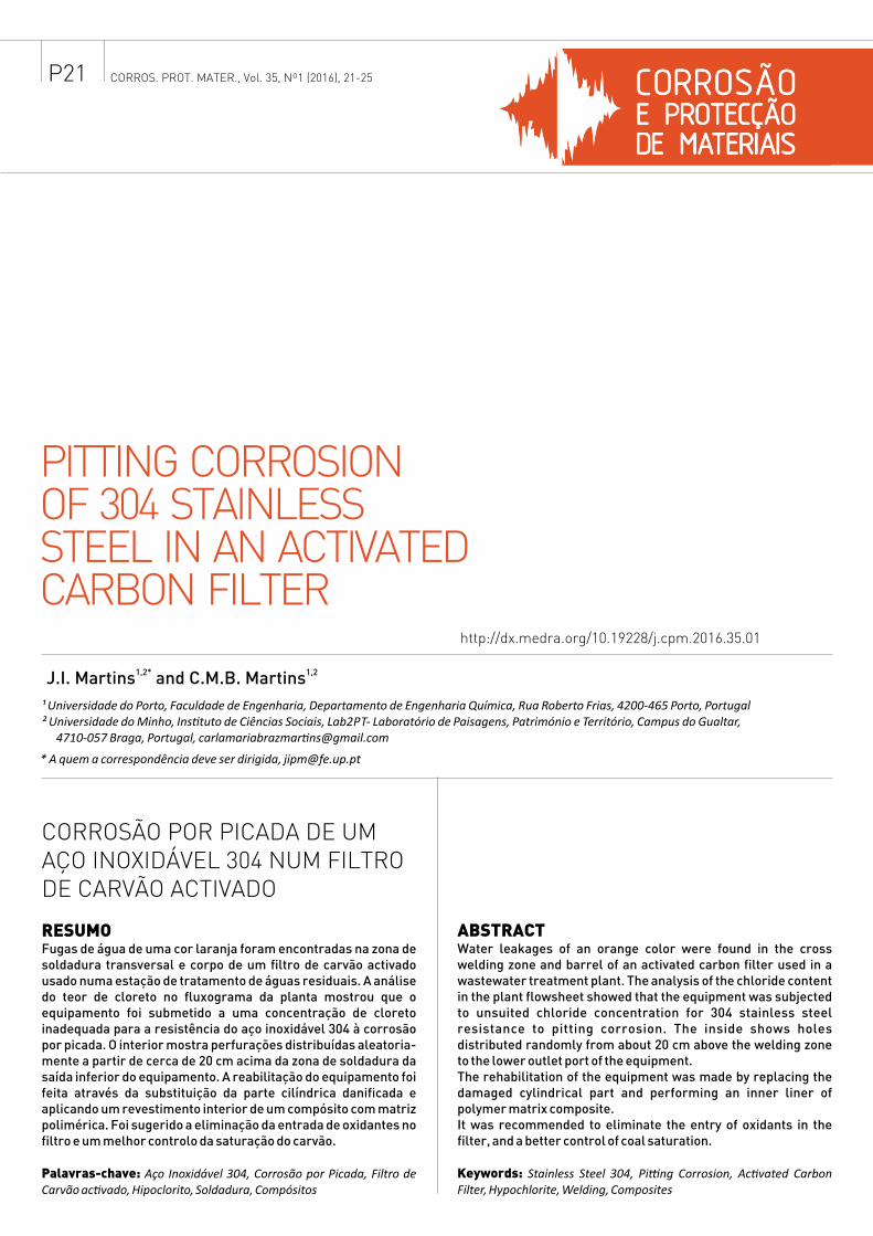
Fig. 1 - Activated carbon filter.
a) Equipment: h = 2.80 m, D = 0.90 m, e = 2 mm (body) and 2.5 mm (top and bottom);
material, stainless steel 304;
b) Leakages with orange color in the welding zone;
c) Bubble with leakages under the plastic lining.
After removing the activated carbon, plastic lining and cleaning
the inside of the equipment, it was possible to gather more
information inserted in Fig.2. With all this information, we can
reach the following conclusions:
• The device is coated with plastic on the cylindrical portion except
the area adjacent to the circumferential weld bead, Fig. 1a).
• The water leakages of orange color on the cylindrical body
emanate from the welding bead, Fig. 1b) and Fig. 2a), and from
non-visible holes under the plastic, Fig.1c) and Fig. 2b).
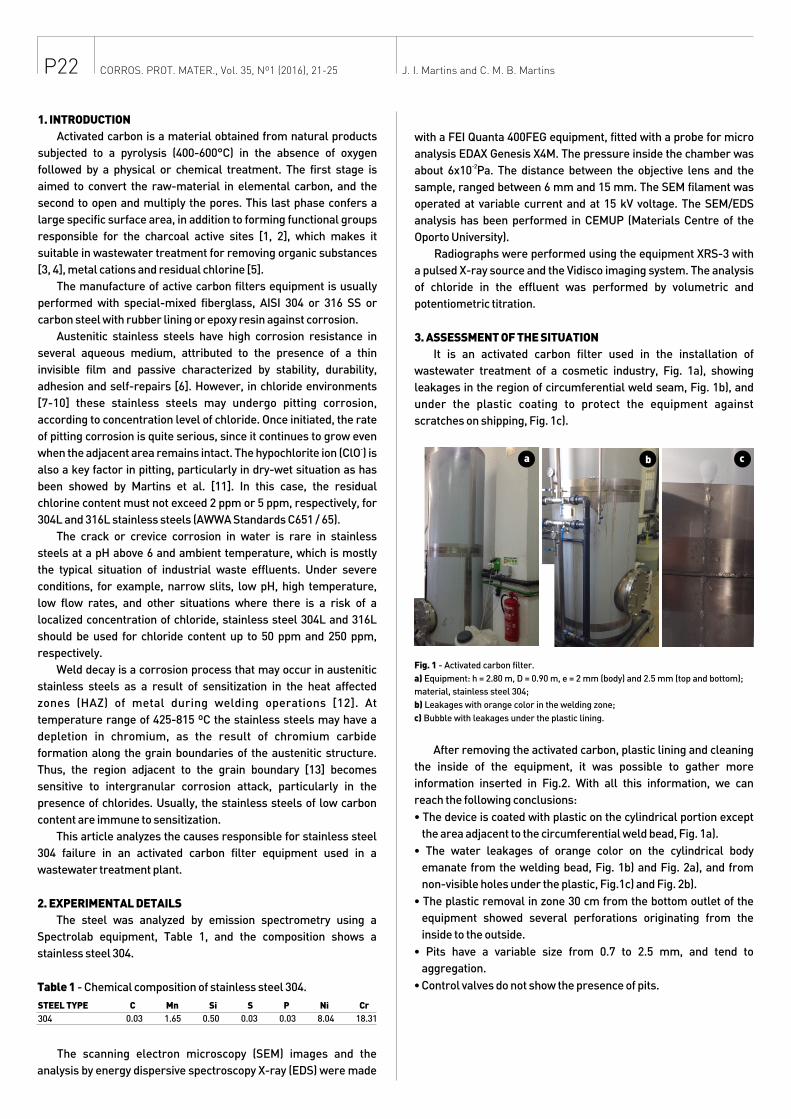
• The plastic removal in zone 30 cm from the bottom outlet of the
equipment showed several perforations originating from the
inside to the outside.
• Pits have a variable size from 0.7 to 2.5 mm, and tend to
aggregation.
• Control valves do not show the presence of pits.
1. INTRODUCTION
Activated carbon is a material obtained from natural products
subjected to a pyrolysis (400-600°C) in the absence of oxygen
followed by a physical or chemical treatment. The first stage is
aimed to convert the raw-material in elemental carbon, and the
second to open and multiply the pores. This last phase confers a
large specific surface area, in addition to forming functional groups
responsible for the charcoal active sites [1, 2], which makes it
suitable in wastewater treatment for removing organic substances
[3, 4], metal cations and residual chlorine [5].
The manufacture of active carbon filters equipment is usually
performed with special-mixed fiberglass, AISI 304 or 316 SS or
carbon steel with rubber lining or epoxy resin against corrosion.
Austenitic stainless steels have high corrosion resistance in
several aqueous medium, attributed to the presence of a thin
invisible film and passive characterized by stability, durability,
adhesion and self-repairs [6]. However, in chloride environments
[7-10] these stainless steels may undergo pitting corrosion,
according to concentration level of chloride. Once initiated, the rate
of pitting corrosion is quite serious, since it continues to grow even -when the adjacent area remains intact. The hypochlorite ion (ClO ) is
also a key factor in pitting, particularly in dry-wet situation as has
been showed by Martins et al. [11]. In this case, the residual
chlorine content must not exceed 2 ppm or 5 ppm, respectively, for
304L and 316L stainless steels (AWWA Standards C651 / 65).
The crack or crevice corrosion in water is rare in stainless
steels at a pH above 6 and ambient temperature, which is mostly
the typical situation of industrial waste effluents. Under severe
conditions, for example, narrow slits, low pH, high temperature,
low flow rates, and other situations where there is a risk of a
localized concentration of chloride, stainless steel 304L and 316L
should be used for chloride content up to 50 ppm and 250 ppm,
respectively.
Weld decay is a corrosion process that may occur in austenitic
stainless steels as a result of sensitization in the heat affected
zones (HAZ) of metal during welding operations [12]. At
temperature range of 425-815 ºC the stainless steels may have a
depletion in chromium, as the result of chromium carbide
formation along the grain boundaries of the austenitic structure.
Thus, the region adjacent to the grain boundary [13] becomes
sensitive to intergranular corrosion attack, particularly in the
presence of chlorides. Usually, the stainless steels of low carbon
content are immune to sensitization.
This article analyzes the causes responsible for stainless steel
304 failure in an activated carbon filter equipment used in a
wastewater treatment plant.
2. EXPERIMENTAL DETAILS
The steel was analyzed by emission spectrometry using a
Spectrolab equipment, Table 1, and the composition shows a
stainless steel 304.
Table 1 - Chemical composition of stainless steel 304.
The scanning electron microscopy (SEM) images and the
analysis by energy dispersive spectroscopy X-ray (EDS) were made
P22
STEEL TYPE C Mn Si S P Ni Cr
304 0.03 1.65 0.50 0.03 0.03 8.04 18.31
a b
J. I. Martins and C. M. B. Martins
c
CORROS. PROT. MATER., Vol. 35, Nº1 (2016), 21-25
Fig. 2 - a) Detail of the weld zone; b) Hole under the plastic; c) Area inside the filter
below the welding; d) Area in the vicinity of the circumferential weld seam; e) and f)
Inside areas below the welding with a reference scale.
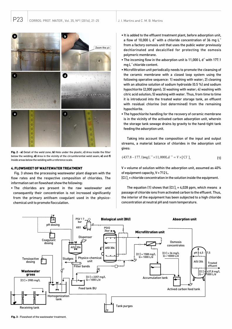
4. FLOWSHEET OF WASTEWATER TREATMENT
Fig. 3 shows the processing wastewater plant diagram with the
flow rates and the respective composition of chlorides. The
information set on flowsheet show the following:
• The chlorides are present in the raw wastewater and
consequently their concentration is not increased significantly
from the primary antifoam coagulant used in the physico-
chemical unit to promote flocculation.
• It is added to the effluent treatment plant, before adsorption unit, -1 -1a flow of 10,000 L d with a chloride concentration of 36 mg L
from a factory osmosis unit that uses the public water previously
dechlorinated and decalcified for protecting the osmosis
polymeric membrane.-1• The incoming flow in the adsorption unit is 11,000 L d with 177.1
-1mg L chloride content.
• Microfiltration unit periodically needs to promote the cleansing of
the ceramic membrane with a closed loop system using the
following operative sequence: 1) washing with water; 2) cleaning
with an alkaline solution of sodium hydroxide (0.5 %) and sodium
hypochlorite (2,000 ppm); 3) washing with water; 4) washing with
citric acid solution; 5) washing with water. Thus, from time to time
it is introduced into the treated water storage tank, an effluent
with residual chlorine (not determined) from the remaining
hypochlorite.
• The hypochlorite handling for the recovery of ceramic membrane
is in the vicinity of the activated carbon adsorption unit, wherein
the storage tank sewage drains by gravity to the hand-tight tank
feeding the adsorption unit.
Taking into account the composition of the input and output
streams, a material balance of chlorides in the adsorption unit
gives:
(1)
V = volume of solution within the adsorption unit, assumed as 40%
of equipment capacity, V = 712 L.-[Cl ] = chloride concentration in the solution inside the equipment. s
-The equation (1) shows that [Cl ] = 4,028 ppm, which means a s
passage of chloride ions from activated carbon to the effluent. Thus,
the interior of the equipment has been subjected to a high chloride
concentration at neutral pH and room temperature.
P23
Zoom the pit
a b
c d
e f
J. I. Martins and C. M. B. MartinsCORROS. PROT. MATER., Vol. 35, Nº1 (2016), 21-25
Fig. 3 - Flowsheet of the wastewater treatment.
Tank purges
Actived carbon feed tank
Accumulation tank
Osmosisconcentrates
Microfiltration unit
Wastewatergross
Biological unit (BU) Absorption unit
Tensioactivedosing
Coagulantdosing
pH dosing
Receiving tank
Homogenization tank
Feed tank BU
-[Cl ] = 3985 mg/L
-[Cl ] = 2257 mg/LQ = 1000 L/d
Filter bands
Sludges Physico-chemicalunit
Dispenser
-[Cl ] = 1588 mg/LQ = 1000 L/d
-[Cl ] = 36 mg/LQ = 10000 L/d
-[Cl ] = 437,8 mg/LQ = 1. 1000 L/d
AISI 304Treatedeffluent
pH = 6,5 - 7,5
PSV 1 7bar
KR1 PSV23bar
AISI 304AISI 304
P24
5. TREATMENT OF WASTEWATER WITH ACTIVATED CHARCOAL
Activated carbon is commonly used in drinking water treatment
or wastewater, for color removal, odor, and bad taste, through an
adsorption mechanism.
Chemicals such as chlorine and hypochlorite employed in
disinfection or organic material oxidation in the water are removed
by a process somewhat different from the simple adsorption. In this
case there is a catalytic decomposition of the oxidizing agent on the
surface of the activated carbon according to the following reactions:
(2)
(3)
(4)
According to reactions (2) and (3), the cleaning of the ceramic
membrane of the microfiltration unit will be an operation
responsible for the chloride concentration increasing in the tank
inside the adsorption unit.
The adsorption isotherms establish the relationship between
the amount or concentration of adsorbed on the adsorbent (q ), and e
the equilibrium concentration of the adsorbate in the solution (C ). e
The equilibrium data for plotting this relationship, Fig. 4a), are
obtained from "batch" experiments using the following expression:
(5)
V = volume of the solution used in the test (L).-1C = initial concentration of adsorbate in the solution (mg L ).o
C = concentration of adsorbate in equilibrium in the solution (mg e
-1 L ).
q = concentration of the adsorbate in the adsorbent in equilibrium e
-1 with the solution (mg g of adsorbent).
Fig. 4 - a) Isothermal of carbon adsorption; b) Breakthrough curve.
After some time, the loading of the carbon increases, the
available adsorption places are filled, and breakthrough of the
chloride in the effluent occurs, Fig. 4b). However, there may be
chloride transfer from the solid phase to the effluent even when the
adsorbent is not saturated. The inverse behavior of the activated
carbon is explained by analyzing the equilibrium adsorption
isotherm data, Fig. 4a). Indeed, it is only necessary that the input
effluent to the adsorption unit has a chloride concentration (Ce1)
smaller than the equilibrium concentration (Ce2) related with the
content accumulated in the adsorbent (qe2). In this case it is
established a concentration gradient of chloride ion that will
impose on the system an evolution for a pseudo equilibrium
position with chloride concentrations q and C , respectively, to the es es
adsorbent and solution, so that it satisfies the following material
balance:
(6)
V = volume of solution within the adsorption unit (L).- -1C = [Cl ] = chloride concentration in the solution (mg L ].es s
M = total mass of activated carbon inside de filter (g).c
q = concentration of the adsorbate in the adsorbent at pseudo es
-1 equilibrium (mg g of carbon).
q = concentration of the adsorbate in the adsorbent at point 2 in e2
-1 equilibrium isotherm (mg g of carbon).
According to the transcript about the flowsheet of the
wastewater plant this situation can occur several times.
6. RESULTS
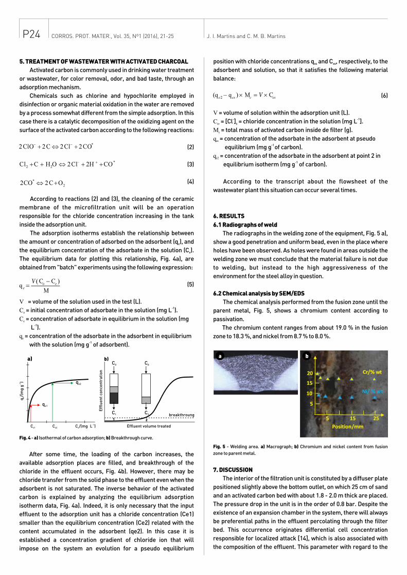
6.1 Radiographs of weld
The radiographs in the welding zone of the equipment, Fig. 5 a),
show a good penetration and uniform bead, even in the place where
holes have been observed. As holes were found in areas outside the
welding zone we must conclude that the material failure is not due
to welding, but instead to the high aggressiveness of the
environment for the steel alloy in question.
6.2 Chemical analysis by SEM/EDS
The chemical analysis performed from the fusion zone until the
parent metal, Fig. 5, shows a chromium content according to
passivation.
The chromium content ranges from about 19.0 % in the fusion
zone to 18.3 %, and nickel from 8.7 % to 8.0 %.
Fig. 5 - Welding area. a) Macrograph; b) Chromium and nickel content from fusion
zone to parent metal.
7. DISCUSSION
The interior of the filtration unit is constituted by a diffuser plate
positioned slightly above the bottom outlet, on which 25 cm of sand
and an activated carbon bed with about 1.8 - 2.0 m thick are placed.
The pressure drop in the unit is in the order of 0.8 bar. Despite the
existence of an expansion chamber in the system, there will always
be preferential paths in the effluent percolating through the filter
bed. This occurrence originates differential cell concentration
responsible for localized attack [14], which is also associated with
the composition of the effluent. This parameter with regard to the
J. I. Martins and C. M. B. MartinsCORROS. PROT. MATER., Vol. 35, Nº1 (2016), 21-25
a b
-1q
/(m
g g
)e
C e1 C e2
a)
q e1
q e2
Eff
lue
nt
con
cen
tra
tio
n
b)
breakthroung
C /(mg e
-1L ) Effluent volume treated
C 1 C 2
C 0 C 0
1 2
P25
chloride content is essential, in view of the adverse effect of this
anion on the 304 stainless steel passivation. The concentration of
sodium chloride may increase inside the filter unit when the
activated carbon is close to saturation by one of the following ways:
1 - When cleaning the ceramic membrane microfiltration unit, since
residual chlorine in contact with activated coal is converted into the
chloride according to reaction 2) and 3);
2 - When the concentration of chlorides in the input chloride
effluent has a lower value corresponding to the equilibrium
saturation of carbon. In this case, it is noted that the interior
material was subjected to a concentration (4,028 ppm) much
greater than the value taken as acceptable. The aggressiveness of
the hypochlorite ion in the stainless steel is also associated to its
cathodic behavior besides the reduction reaction of oxygen [11].
(7)
In order to solve the problems in the activated carbon the
following actions were taken:
1 - Eliminate chlorine in the input stream of the filter unit coming
from the ceramic membrane cleaning. The discharge of the
downstream effluent must be made to a tank containing a reducing
agent (e.g., sodium bisulfite) for limiting the residual chlorine
content to 0.01 ppm before entering the public network.
2 - Remove the plastic coating, which is only performed for
protection of the equipment during road or railway transport.
3 - Control the chloride content in the input stream and output of
adsorption unit to set the breakthrough of chlorides suitable to
avoid the inversion of the adsorption mechanism of the activated
carbon.
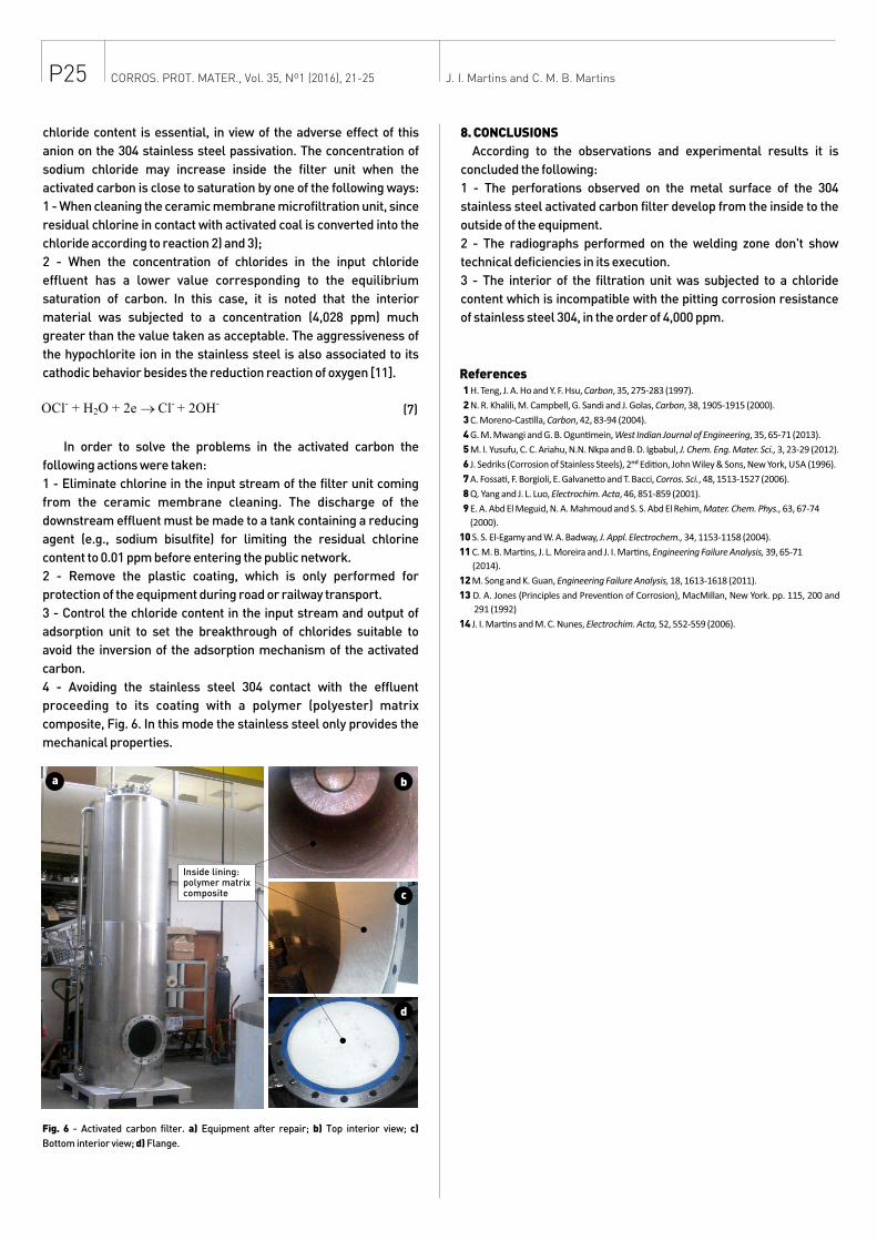
4 - Avoiding the stainless steel 304 contact with the effluent
proceeding to its coating with a polymer (polyester) matrix
composite, Fig. 6. In this mode the stainless steel only provides the
mechanical properties.
Fig. 6 - Activated carbon filter. a) Equipment after repair; b) Top interior view; c)
Bottom interior view; d) Flange.
J. I. Martins and C. M. B. Martins
References 1 H. Teng, J. A. Ho and Y. F. Hsu, Carbon, 35, 275-283 (1997).
2 N. R. Khalili, M. Campbell, G. Sandi and J. Golas, Carbon, 38, 1905-1915 (2000).
3 C. Moreno-Cas�lla, Carbon, 42, 83-94 (2004).
4 G. M. Mwangi and G. B. Ogun�mein, West Indian Journal of Engineering, 35, 65-71 (2013).
5 M. I. Yusufu, C. C. Ariahu, N.N. Nkpa and B. D. Igbabul, J. Chem. Eng. Mater. Sci., 3, 23-29 (2012).
6 J. Sedriks (Corrosion of Stainless Steels), 2ⁿ� Edi�on, John Wiley & Sons, New York, USA (1996).
7 A. Fossa�, F. Borgioli, E. Galvane�o and T. Bacci, Corros. Sci., 48, 1513-1527 (2006).
8 Q. Yang and J. L. Luo, Electrochim. Acta, 46, 851-859 (2001).
9 E. A. Abd El Meguid, N. A. Mahmoud and S. S. Abd El Rehim, Mater. Chem. Phys., 63, 67-74
(2000).
10 S. S. El-Egamy and W. A. Badway, J. Appl. Electrochem., 34, 1153-1158 (2004).
11 C. M. B. Mar�ns, J. L. Moreira and J. I. Mar�ns, Engineering Failure Analysis, 39, 65-71
(2014).
12 M. Song and K. Guan, Engineering Failure Analysis, 18, 1613-1618 (2011).
13 D. A. Jones (Principles and Preven�on of Corrosion), MacMillan, New York. pp. 115, 200 and
291 (1992)
14 J. I. Mar�ns and M. C. Nunes, Electrochim. Acta, 52, 552-559 (2006).
a b
d
Inside lining:polymer matrixcomposite c
CORROS. PROT. MATER., Vol. 35, Nº1 (2016), 21-25
8. CONCLUSIONS
According to the observations and experimental results it is
concluded the following:
1 - The perforations observed on the metal surface of the 304
stainless steel activated carbon filter develop from the inside to the
outside of the equipment.
2 - The radiographs performed on the welding zone don't show
technical deficiencies in its execution.
3 - The interior of the filtration unit was subjected to a chloride
content which is incompatible with the pitting corrosion resistance
of stainless steel 304, in the order of 4,000 ppm.