Sponsored by the U.S. Department of Defense© 2005 by Carnegie Mellon University
1
Pittsburgh, PA 15213-3890
Current Best Practices in Software Architecture
Paul ClementsSoftware Engineering Institute
Carnegie Mellon UniversityApril 2006
Tandil, Argentina
© 2005 by Carnegie Mellon University 2
Applied R&D laboratory situated as a college-level unit at Carnegie Mellon University, Pittsburgh, PA, USA
Established in 1984
Technical staff of 335
Offices in Pittsburgh, Pennsylvania, Arlington, Virginia, and Frankfurt, Germany
Purpose: Help others makemeasured improvements in theirsoftware engineering practices
Software Engineering Institute
© 2005 by Carnegie Mellon University 3
One of 5-6 programs at the SEI; approx. 30 people. Our goal is to make improvements in
• Software product line engineering
• Predictable assembly of certifiable components
• Software architecture
• Creation
• Documentation
• Evaluation
• Use in system-building
Product Line Systems Program
© 2005 by Carnegie Mellon University 5
Topic
What do we mean by software architecture?
Why is it important?
© 2005 by Carnegie Mellon University 6
Software Architecture’s role in Software Engineering
Some say that software engineering is about creating high-quality multi-version multi-person software.
If we were just building a single system, all by ourselves, that was never going to change, all we would need is programming.
© 2005 by Carnegie Mellon University 7
Multi-personFor non-trivial software, teams of people cooperate to build it. Teams may be• In the same room• In the same building• In the same country• On the same planet• …or not.
Our systems need to be decomposable into pieces, such that• Teams can work in parallel• Inter-team communication is not too burdensome
© 2005 by Carnegie Mellon University 8
Multi-versionAt the dawn of computer science, people were most concerned with programs that computed the right answer.• Ballistic calculations• Numerical problems• Simulations and models of real-world processes
© 2005 by Carnegie Mellon University 9
Multi-versionIn the late 1960s and early 1970s, people like EdsgerDijkstra, David Parnas, Fred Brooks, Anthony Hoare, and Harlan Mills were arguing that this was not enough.
They argued that systems could be constructed in better ways• To make changes easier.• To make the programs easier to understand• To make the programs less likely to contain errors• To make the programs easier to test
They argued that structure matters!
© 2005 by Carnegie Mellon University 10
Edsger Dijkstra (1930-2002)
Contributions to architecture
•“On the T.H.E. Operating System” (1968)
•Described the classic operatingsystem design,
•A brief appendix describessemaphores.
•May have been the first significant and/or popular report on layered systems
© 2005 by Carnegie Mellon University 11
David ParnasContributions to architecture
•“On the Criteria for DecomposingSystems into Modules” (1972) gave us information-hiding as a design principle.From outside, we can work with a component only by its interface!
•“Designing Software for Ease of Extension and Contraction” (1975) introduced a useful architecturalrelation: “uses”
•“On a ‘Buzzword’: ‘HierarchicallyStructured Systems’” (1976) taughtus that systems have many structures.
© 2005 by Carnegie Mellon University 12
Managing ChangeToday we know that usually, most of the cost of a piece of software comes after it has been deployed for the first time.
Maintenance is very expensive. Anything we can do to make systems easier to change will save money in the long run.
Planning and designing for change is a very important part of software engineering.
© 2005 by Carnegie Mellon University 13
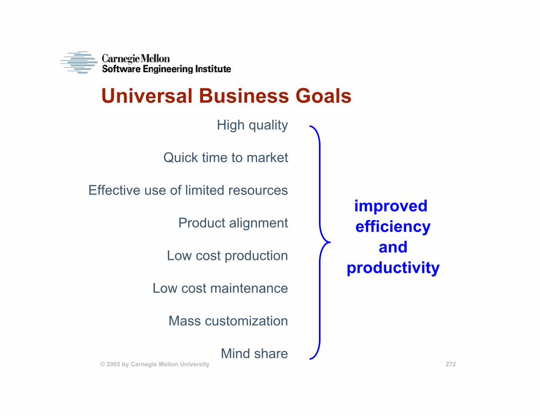
High qualitySince the early times, other qualities have joined “ease of change” as important parts of software engineering.• Performance• Security• Availability• What others?
© 2005 by Carnegie Mellon University 14
High qualityIn fact, some say that software engineering is about the achievement of quality attributes in a software-intensive system.
It turns out that getting the right answer has become the easy part.
Does this surprise you?
© 2005 by Carnegie Mellon University 15
Quality attributes
A system that computes the right answer – i.e., has the right functionality -- but• Takes too long to do it• Allows hackers to break in and steal its data• Is down too much of the time• Cannot be changed in less than six months
…is not going to be a successful system. Nobody will want to use it. Nobody will buy it.
© 2005 by Carnegie Mellon University 16
Quality attributes
If we accept the importance of quality attributes, then we need to understand how to specify them…• Our customer has to tell us what he wants• Our architect and designers must understand it• Our programmers have to achieve it• Our testers have to test for it
…and how to design and build software to achieve them.
Software architecture helps with this.
© 2005 by Carnegie Mellon University 17
QA’s fall into two groups“Run-time” QA’s• We can measure how well a system exhibits these by
watching the system in operation• Performance, security, availability, …
“Non-run-time” QA’s• We can measure these by watching a team in operation• Maintainability, portability, buildability, time to market…
© 2005 by Carnegie Mellon University 18
Software architectureThe rise of software architecture has resulted from two trends:• Recognition of the importance of quality attributes
- Increasingly “time to market” is critical• The development of very large and very complex
systems.
© 2005 by Carnegie Mellon University 19
Software architectureLarge-scale design decisions cannot be made by programmers.• Have limited visibility and short-term
perspectives• Trained in technology solutions to
specific problems.
Teams can only be coordinated, and QA’s can only be achieved, by making broad design decisions that apply to the entire system – all of its elements.
© 2005 by Carnegie Mellon University 20
Summary so farWhat do we know so far? A software architecture• Exists to achieve a system’s quality attributes• Exists to allow parallel development by distributed
teams (a special kind of quality attribute)• Involves decomposing a whole into parts• Involves system-wide design decisions such as
- How the parts work together to achieve the system’s function and goals
© 2005 by Carnegie Mellon University 21
Software architecture and structureSoftware architecture is largely about structure:• What the pieces are• What each one’s responsibility is• How the pieces work together
© 2005 by Carnegie Mellon University 22
How does structure help?By concentrating on structure, we treat the pieces as atomic, as black boxes. This reduces detail we have to tend to, and we can postpone that consideration until later.
It separates concerns between structure (the pieces) and the details of implementing the pieces (which is a job we give to programmers).
Suppressing the internal details of the elements does not affect how the elements are used or how they relate to or interact with other elements.
It makes an architecture an abstraction of a system –which is a simplification.
© 2005 by Carnegie Mellon University 23
The Ascendance of Software ArchitectureOver the past 10 years, software architecture has emerged as the prominent paradigm in large-system development.There are:• worldwide conferences devoted to it• books devoted to it• defined “architect” roles in organizations• courses and training for it
© 2005 by Carnegie Mellon University 24
And yet...It is still not well understood in some circles.
Some organizations have no “architect” position. Others have the position but it is informally defined.
Some organizations are still proceeding to development without an architecture in place.
The tools of the trade -- styles and patterns, views, evaluation -- are used sparingly if at all.
© 2005 by Carnegie Mellon University 25
Role of Software ArchitectureIf the only criterion for software was to get the right answer, we would not need architectures―unstructured, monolithic systems would suffice.But other things also matter, such as• modifiability• time of development (time to market)• performance• coordination of work teams
System qualities are largely dependent on architectural decisions.• All design involves tradeoffs in system qualities.• The earlier we reason about tradeoffs, the better.
© 2005 by Carnegie Mellon University 26
What is your definition of software architecture?The way that you partition a system or software process for defining the teams that work on it.
A view or a structure of the main components of the system and how they interact.
A tool for managing complexity and an abstraction of reality.
© 2005 by Carnegie Mellon University 27
What Is Software Architecture?
Software architecture is the structure or structures of the system, which comprise software elements, the externally visible properties of these elements, and the relationships among them.
Bass, L.; Clements, P.; & Kazman, R. Software Architecture in Practice, Second Edition. Boston, MA: Addison-Wesley, 2003.
© 2005 by Carnegie Mellon University 28
Implications of this Definition Every system has an architecture. If you don’t explicitly develop an architecture, you will get one anyway. • Every system is composed of elements and there are
relationships among them.
Just having an architecture is different from having an architecture that is known to everyone:• Communicating (documenting) the architecture becomes
an important concern.
The architecture might not be the right one.• Evaluating the architecture becomes an important
concern.
© 2005 by Carnegie Mellon University 29
“Externally visible properties”?This refers to those assumptions that one element can make about another element such as• the services it provides• how long it takes• how it handles failures • how it uses shared resources
Elements interact with each other via interfaces that partition details into public and private parts.Architecture is concerned with the public side of this division.
© 2005 by Carnegie Mellon University 30
Structures: Plural!Systems can and do have many structures.• No single structure can be the architecture.• The set of candidate structures is not fixed or prescribed.• Relationships and elements might be runtime related such
as- “sends data to,” “invokes,” or “signals”- processes or tasks
• Relationships and elements might be nonruntime related such as- “is a submodule of,” “inherits from,” or “is allocated to
team X for implementation”- a class or library
© 2005 by Carnegie Mellon University 31
Structures: Plural! This means that box-and-line drawings alone are not architectures; but they are just a starting point.• You might imagine the
behavior of a box labeled “database” or “executive” --but that’s all
• You need to add specifications and properties.
• You need to specify what the boxes are and what the lines mean!
© 2005 by Carnegie Mellon University 32
Box-and-line drawingsBox-and-line diagrams are a common form of architectural notation.
But what do they mean?
If you use a box-and-line diagram, always define precisely what the boxes and lines mean.
If you see a box-and-line diagram, ask the owner what it means. The result is usually entertaining.
Are these modules? Objects? Classes? Processes? Functions? Code units? Execution units? Other?
?
? ??
??
?
?
??
?
?
??
© 2005 by Carnegie Mellon University 33
Old ideas die hard
If you hear someone say
“Architecture is the overall structure of the system.”
…I hope you will disagree.
…I hope you will know how to answer them.
© 2005 by Carnegie Mellon University 34
Why is architecture so valuable?
Why is it worth studying and building?
Why is it worth investing in?
© 2005 by Carnegie Mellon University 35
Communication Vehicle among StakeholdersArchitecture provides a common language in which the architect can communicate with the stakeholders, and stakeholders can communicate with each other.
This happens when • negotiating requirements with users and other
stakeholders• keeping the customer informed of progress and cost• implementing management decisions and allocations• Informing stakeholders about design decisions and
tradeoffs
© 2005 by Carnegie Mellon University 36
Architecture Constrains the Implementation
An architecture defines constraints on an implementation.• Architectures are descriptive and prescriptive
- descriptive for communication- prescriptive for design and implementation
• Global resource allocation decisions constrain implementations of individual components
• System tradeoffs regarding quality attributes are architectural.- Not all QA’s are possible all at once. We might
have to (for example) give up some reliability to gain some performance. Architects make these tradeoffs.
© 2005 by Carnegie Mellon University 37
The Development Project is Organized Around Architectural Elements
The architecture influences the organizational structure for development/maintenance efforts. Examples include• division into teams• assignment of work• units for budgeting, planning by management• basis of work breakdown structure• organization of documentation• organization of CM libraries• basis of integration• basis of test plans, testing• basis of maintenance• Incremental deployment
© 2005 by Carnegie Mellon University 38
Architecture Permits/Precludes Achievement of Quality Attributes
For example
If you desire Examineperformance inter-component communication
modifiability component responsibilities
security inter-component communication,specialized components (e. g., kernels)
scalability localization of resources
ability to subset inter-component usage
reusability inter-component coupling
© 2005 by Carnegie Mellon University 39
Architecture is Key to Managing Change
An architecture helps reason about and manage change.• important since ≈80% of effort in systems occurs after
deploymentArchitecture divides all changes into three classes:• local: modifying a single component• non-local: modifying several components• architectural: modifying the gross system topology,
communication, and coordination mechanismsA “good” architecture is one in which the most likely changes are also the easiest to make.
© 2005 by Carnegie Mellon University 40
Architecture is Basis for Incremental Development
An architecture helps with evolutionary prototyping and incremental delivery.• Architecture serves as a skeletal framework into which
components can be plugged.• By segregating functionality into appropriate
components, experimentation is easier.• Risky elements of the system can be identified via the
architecture and mitigated with targeted prototypes.
© 2005 by Carnegie Mellon University 41
Architecture is a Reusable Model
An architecture is an abstraction: enables a one-to-many mapping (one architecture, many systems).
Systems can be built from large, externally developed components that are tied together via architecture.
Architecture is the basis for product (system) commonality.
Entire software product lines can share a single architecture.
© 2005 by Carnegie Mellon University 42
Architecture and structure, re-visited
Architecture is about structure. But which structure? Software has more than one.
Parnas made this observation in 1976 (“On a ‘Buzzword’: ‘Hierarchically Structured Systems’”).• Systems have many kinds of “pieces”: programs,
objects, classes, modules, processes, frameworks, tasks, threads…
• Each one defines a different structure.• Which one is the architecture?
Answer: All of them might be.
© 2005 by Carnegie Mellon University 43
Structures and Views A representation of a structure (or a set of structures) is a
view.
Modern treatments of architecture all recognize the importance of multiple architectural views.
Modern software systems are too complex to grasp all at once. At any moment, we restrict our attention to a small number of a software system’s structures.
To communicate meaningfully about an architecture, we must make it clear which structure or structures we are discussing…that is, which view we are taking of the architecture.
© 2005 by Carnegie Mellon University 44
• structure – an actual set of architectural elements as they exist in software or hardware
• view – a representation of a coherent set of architectural elements, as written by and read by system stakeholders. A view represents a a set of elements and the relationships between those elements.
Structures and Views - 2
© 2005 by Carnegie Mellon University 45
Example of Multiple ViewsSoftware Architecture for A-7E Corsair II Aircraft • U. S. carrier-based, light attack aircraft• Used from the 1960s through the 1980s• Small computer on board for navigation, weapons
delivery
© 2005 by Carnegie Mellon University 46
Module Decomposition View (2 Levels)H
ardw
are-
Hid
ing
Mod
ule
Deviceinterfacemodule
Extendedcomputermodule
Beh
avio
r-H
idin
g M
odul
e
Functiondrivermodule
Sharedservicesmodule
Data bankermodule
Physicalmodels module
Applicationdata types mod.
Filterbehavior module
Softwareutilities module
Systemgeneration mod.So
ftwar
e -D
ecis
ion-
Hid
ing
Mod
ule
© 2005 by Carnegie Mellon University 47
Data Flow View
Device interfaces
Data banker
Shared services
Function drivers Filter behaviors
Physical models
sensor inputs
computed values stored values
computed values
storedvalues
valuesto display
filteredvalues
sensorvalues
calculatedcalculatedrealreal--worldworld
valuesvalues
Pilot, external world
© 2005 by Carnegie Mellon University 48
Layers ViewFunction drivers
Extended computer
Application data types
Device interfaces
Databanker
Physicalmodels
Filterbehaviors
Shared services
Softwareutilities
© 2005 by Carnegie Mellon University 49
Views -1
An architecture is a very complicated construct -- too complicated to be seen all at once.
Views are a way to manage complexity.
Each view can be used to answer a different question about the architecture• What are the major execution units and data stores?• What software is other software allowed to use?• How does data flow through the system?• How is the software deployed onto hardware?
© 2005 by Carnegie Mellon University 50
Views -2A view is a representationof a set of architecturalelements and therelations associatedwith them.
Not all architecturalelements -- some of them.
A view binds elementtypes and relation typesof interest, and showsthose.
All information
Some information
© 2005 by Carnegie Mellon University 51
Views -3 In the 1990s, the trend was to prescribe a set of views.• Rational (Kruchten) 4+1 view model• Siemens Four-Views Model for architecture• Others
Now the trend is to prescribe choosing the right set of views from an open set of possibilities.
IEEE/ANSI 1471-2000 (“Recommended Practice for Architectural Description of Software-Intensive Systems”) exemplifies this approach.
More on this when we discuss documentation.
© 2005 by Carnegie Mellon University 52
Architectural StructuresArchitectural structures (and hence views) can be divided
into three types:
1. “module” structures – consisting of elements that are units of implementation called modules
2. “component-and-connector” structures – consisting of runtime components (units of computation) and the connectors (communication paths) between them
3. “allocation” structures – consisting of software elements and their relationships to elements in external environments in which the software is created and executed
© 2005 by Carnegie Mellon University 53
Example Module StructuresDecomposition structure – consisting of modules that are related via the “is a submodule of” relation
Uses structure – consisting of modules that are related via the “uses” relation (i.e., one module uses the services provided by another module)
Layered structure – consisting of modules that are partitioned into groups of related and coherent functionality. Each group represents one layer in the overall structure.
Class/generalization structure – consisting of modules called classes that are related via the “inherits from” or “is an instance” of relations
© 2005 by Carnegie Mellon University 54
Example Component-and-Connector StructuresProcess structure – consisting of processes or threads that are connected by communication, synchronization, and/or exclusion operations
Concurrency structure – consisting of components and connectors where connectors represent “logical threads”
Shared-data (repository) structure – consisting of components and connectors that create, store, and access persistent data
Client-server structure – consisting of cooperating clients and servers and the connectors between them (i.e., the protocols and messages they share)
© 2005 by Carnegie Mellon University 55
Example Allocation StructuresDeployment structure – consisting of software elements and their allocation to hardware and communication elements
Implementation structure – consisting of software elements and their mapping to file structures in the development, integration, and configuration control environments
Work assignment structure – consisting of modules and how they are assigned to the development teams responsible for implementing and integrating them
© 2005 by Carnegie Mellon University 56
Architectural Structures Summary
Component-and-Connector
Client-Server
Concurrency
Process
Shared-Data
…
Module
Decomposition Class/Generalization
Uses
Layers
…
Allocation
Work Assignment
Deployment Implementation
…
© 2005 by Carnegie Mellon University 57
Using structures and viewsEach structure provides the architect with an engineering handle on some aspect of the system. For example:• Carefully designing the module decomposition structure
has a powerful effect on modifiability.• Carefully designing the module “uses” structure has a
powerful effect in the ability to field subsets and develop incrementally.
• Carefully designing the deployment structure has a powerful effect on performance and availability.
• Carefully designing the various C&C structures has a powerful effect on run-time QA’s such as performance or security.
© 2005 by Carnegie Mellon University 58
Using structures and viewsArchitects choose the structures that need to engineer based on the important quality attribute drivers.
They record their designs using the corresponding views.
© 2005 by Carnegie Mellon University 59
Other kinds of architectureSince the ascendance of software architecture, other kinds of architecture have arisen. Two in particular are:• enterprise architecture• system architecture
What do these terms mean to you?
© 2005 by Carnegie Mellon University 60
Enterprise Architectures
Enterprise architecture is a means for describing business structures and processes that connect business structures.1
• It describes the flow of information and activities between various groups within the enterprise that accomplish some overall business activity.
• Enterprise architectures may or may not be supported by computer systems.
• Software and its design are not typically addressed explicitly in an enterprise architecture.
1 Zachman, John A. "A Framework for Information Systems Architecture." IBM Systems Journal26, 3 (1987): 276-292.
© 2005 by Carnegie Mellon University 61
System Architecture
A system architecture is a means for describing the elements and interactions of a complete system including its hardware elements and its software elements.
System architecture is concerned with the elements of the system and their contribution toward the system’s goal, but not with their substructure.
See: Rechtin, E. Systems Architecting: Creating and Building Complex Systems. Englewood Cliffs, NJ: Prentice-Hall, 1991.
© 2005 by Carnegie Mellon University 62
Where Does Software Architecture Fit?Enterprise architecture and system architecture provide an environment in which software lives.• Both provide requirements and constraints to
which software architecture must adhere.• Elements of both are likely to contain software
architecture.
© 2005 by Carnegie Mellon University 63
SummarySoftware architecture refers to the structures of systems: their elements, externally visible properties, and relationships among them.
Software architecture represents the earliest and farthest-reaching design decisions about a system.
Software architecture permits or precludes nearly every quality attribute for a system…
…which is what software engineering is about achieving.
© 2005 by Carnegie Mellon University 64
Next:We’ll discuss where architectures come from:
• Understanding architectural requirements: Quality attributes, quality attribute scenarios, quality requirements elicitation and capture
• The Architecture Business Cycle: forces that shape the architecture, and where they come from
© 2005 by Carnegie Mellon University 65
Specifying quality attributes
If quality attributes are so important, we need a way to communicate them unambiguously.
© 2005 by Carnegie Mellon University 66
Specifying quality attributesSuppose our customer tells us he wants a system that
runs very fast.
Is that helpful? (Notvery.) What would help?
I want a system that runs very fast!
© 2005 by Carnegie Mellon University 67
Specifying quality attributesHow fast?
How do you measure that?
You can’t everything run fast. What do you really care about?
© 2005 by Carnegie Mellon University 68
Specifying quality attributesSuppose our customer tells us he wants a system that is
very secure.
Is that helpful? (Notvery.) What would help?
I want a system that is very secure!
© 2005 by Carnegie Mellon University 69
Specifying quality attributesHow secure?
How do you measure that?
You can’t have totally secure software. What do you really care about, or what threats are the most important to guard against?
© 2005 by Carnegie Mellon University 70
Specifying quality attributesSuppose our customer tells us he wants a system that is
very easy to change.
Is that helpful? (Notvery.) What would help?
I want a system that is very easy to change!
© 2005 by Carnegie Mellon University 71
Specifying quality attributesHow easy?
How do you measure that?
You can’t make everything equally easy to change. Which changes do you really care about?
© 2005 by Carnegie Mellon University 72
Specifying quality attributes
I want a system that…
Be quiet!
© 2005 by Carnegie Mellon University 73
Specifying quality attributesConclusion: Just naming a quality attribute doesn’t help very much.
We can’t build software with just that.
We need to be more specific.
Most people use quality attribute scenarios to capture quality attributes.
© 2005 by Carnegie Mellon University 74
ScenariosA scenario is a little story describing an interaction
between a stakeholder and a system.
A use case is a kind of scenario. The stakeholder is the user. The interaction is a functional use of the system.
“The user pushes this button, and this result occurs.”
© 2005 by Carnegie Mellon University 75
ScenariosWe can generalize the notion of a use case to come up with quality attribute scenarios.
A quality attribute scenario is a short description of how a system is required to respond to some stimulus.
© 2005 by Carnegie Mellon University 76
QA ScenariosA quality attribute scenario has six parts:• source – an entity that generates a stimulus• stimulus – a condition that affects the system• artifact – the part of that was stimulated by the
stimulus• environment – the condition under which the
stimulus occurred• response – the activity that results because of the
stimulus• response measure – the measure by which the
system’s response will be evaluated
© 2005 by Carnegie Mellon University 77
A QA Scenario for Availability• An unanticipated external message is received by a
process during normal operation. The process informs the operator of the message’s receipt, and the system continues to operate with no downtime.
1. source – external2. stimulus – unanticipated message received3. artifact – process4. environment – during normal operation5. response – system continues to operate6. response measure – zero downtime
© 2005 by Carnegie Mellon University 78
A QA Scenario for Modifiability• During maintenance, a change is made to the system’s
rules engine. The change is completed in one day.
1. source – requestor of the change2. stimulus – a change is made3. artifact – rules engine4. environment – during maintenance5. response – the change is completed6. response measure – …in one day
© 2005 by Carnegie Mellon University 79
A QA Scenario for Security• During peak operation, an unauthorized intruder tries
to download prohibited data via the system administrator’s interface. The system detects the attempt, blocks access, and notifies authorities within 15 seconds.
1. source – an unauthorized intruder2. stimulus – tries to download prohibited data3. artifact – system administrator’s interface4. environment – during peak operation5. response – the attempt is detected, blocked, reported6. response measure – …within 15 seconds
© 2005 by Carnegie Mellon University 80
Scenarios for other QA’sCan you imagine QA Scenarios for• Usability?• Testability?• Time to market?• Freedom from error?• Others
Q: How many scenarios does it take to specify a quality attribute?
A: As many as you need.
© 2005 by Carnegie Mellon University 81
One QA, many scenariosFor a system we’re about to build:
We might capture several performance scenarios, one for each of:• (Min, max, average) transaction throughput under
(peak, normal) load• (Min, max, average) end-to-end latency for a
transaction
We might capture several security scenarios, one for each of:• Denial of service• Unauthorized access• Non-repudiatability
© 2005 by Carnegie Mellon University 82
One QA, many scenariosFor a system we’re about to build:
We might capture several modifiability scenarios, one for each of:• Adding a new function• Correcting a bug• Changing the platform or middleware• Changing the behavior• Replacing one component with another• Changing the user interface• Etc.
And so forth.
© 2005 by Carnegie Mellon University 83
ExerciseWrite a quality attribute scenario that expresses a requirement for• Modifiability• Security• Usability• Performance• Testability
Take 30 minutes. Plan to read your results to the class.
© 2005 by Carnegie Mellon University 84
More about QAsThere is no standard set of quality attributes
• People disagree on names: Maintainability/modifiability/portability
• People come up with new ones: “calibrate-ability”• There is no standard meaning of what it means to
be “secure”
Scenarios let us avoid all of these problems!
The QAs are defined by the scenarios!
Who tells us what QA’s are important? Stakeholders!
© 2005 by Carnegie Mellon University 85
StakeholdersStakeholders are people with a vested interest in the system. They are the people who can tell us what is needed. They are the people who can tell us if what we are building is the right thing.
We usually think of the user as telling us what is required, but there are many kinds of stakeholders.
© 2005 by Carnegie Mellon University 86
Stakeholders
Who are the stakeholders of an architecture? Name some of the roles.
© 2005 by Carnegie Mellon University 87
Stakeholders have an interest in the construction and operation of a software system. They might include:• customers• users• developers• project managers• marketers• maintainers
Stakeholders have different concerns that they want to guarantee and/or optimize.
Influence of System Stakeholders
© 2005 by Carnegie Mellon University 88
Concerns of System Stakeholders
Marketingstakeholder
Behavior,performance,
security,reliability,usability!
Low cost,keeping people
employed, leveraging existing corporate
assets!
Low cost, timelydelivery, not changed
very often!
Modifiability!Neat features,short time to market,low cost, parity withcompeting products!
Architect
Developmentorganization’smanagementstakeholder
End userstakeholder
Maintenanceorganizationstakeholder
Customerstakeholder
I need a raise!
© 2005 by Carnegie Mellon University 89
Stakeholder InvolvementStakeholders’ quality attribute requirements are seldom documented, which results in• goals not being achieved• conflict between stakeholders
Architects must identify and actively engage stakeholders early in the life cycle to• understand the real constraints of the system (many times,
stakeholders ask for everything!)• manage the stakeholders’ expectations (they can’t have
everything!)• negotiate the system’s priorities• make tradeoffs
© 2005 by Carnegie Mellon University 90
SEI Quality Attribute Workshop (QAW)The QAW is a facilitated method that engages system
stakeholders early in the life cycle to discover the driving quality attributes of a software-intensive system.
Key points about the QAW are that it is• system-centric• stakeholder focused• used before the software architecture has been
created
© 2005 by Carnegie Mellon University 91
QAW Steps
1. QAW Presentation and Introductions
2. Business/Mission Presentation
3. Architectural Plan Presentation
4. Identification of Architectural Drivers
5. Scenario Brainstorming
6. Scenario Consolidation
7. Scenario Prioritization
8. Scenario RefinementIterate as necessary with broader stakeholder community
© 2005 by Carnegie Mellon University 92
Update Architectural VisionRefine RequirementsCreate PrototypesExercise SimulationsCreate Architecture
QAW Benefits and Next Steps
• increased stakeholder communication• clarified quality attribute requirements• informed basis for architectural decisions
QAWQuality AttributeScenarios:• raw• prioritized• refined
EvaluateArchitecture
Can be used to
Potential Next Steps
Potential Benefits
© 2005 by Carnegie Mellon University 93
Architectural RequirementsArchitectural requirements are shaped by quality attribute requirements.
These come from stakeholders.
What else shapes an architecture?
© 2005 by Carnegie Mellon University 94
Development Organization’s Influence on Architectures• An organization may have an investment in certain assets,
such as - existing architectures and products based on them. - a purchased tool environment- training
• The architecture can form the core of a long-term investment to meet the strategic goals.
• The organizational structure can shape the architecture. E.g., a Database Division may influence the architect to include a database in the design.
© 2005 by Carnegie Mellon University 95
Influence of Technical Environment on ArchitecturesThe technical environment that is current when an architecture is designed will influence that architecture.
Today, a business system will almost certainly be• Web-based• Have a main database• Be layered and/or tiered• Be distributed and use commercial middleware• Etc.
It may also use• Agents• Service-oriented architecture• .NET or J2EE or…
It wasn’t always like this.
© 2005 by Carnegie Mellon University 96
Influence of Architect’s Background on ArchitecturesArchitects make choices based on their past experiences:• Good experiences will lead to the replication of
those prior designs that worked well.• Bad experiences will be avoided in new designs,
even if the methods, techniques, and/or technology that led to those bad experiences might work better in subsequent designs.
• An architect’s choices might be influenced by education and training.
© 2005 by Carnegie Mellon University 97
Influences on the Architecture
Architect’s influences
Stakeholders
Developmentorganization
Technicalenvironment
Architect’sexperience
Requirements
System
Architect(s)Architecture
© 2005 by Carnegie Mellon University 98
Architectures Affect the Factors That Influence Them
Once the architecture is created and a system (or systems) built from it, both will affect• the structure and goals of the organization
developing them• customers’ requirements • the architect’s experience in developing
subsequent systems because the corporate experience base has been enhanced
• technology
© 2005 by Carnegie Mellon University 99
How Architectures Affect the Organization – 1Architectures can influence the structure of the organization developing them.
Architectures prescribe the units of software that must be implemented and integrated.
In turn, software units are the basis for• team formation• development, test, and integration activities• resource allocation in schedules and budgets
© 2005 by Carnegie Mellon University 100
How Architectures Affect the Organization – 2Architectures can influence the goals of an organization.
The architecture can provide opportunities for the efficient production and deployment of similar systems.
The organization might adjust its goals to take advantage of new market opportunities based on its architecture-enabled capability.
© 2005 by Carnegie Mellon University 101
How Architectures Affect Customers’ RequirementsArchitectures can influence customers’ requirements:• Knowledge of similarly fielded systems leads customers to
ask for particular kinds of features.
They may even ask for systems using language of the architecture: client-server, .NET, service-oriented, etc.
• Customers will alter their system requirements based on the availability of existing systems and components.
They often save time and money this way.
© 2005 by Carnegie Mellon University 102
How Architectures Affect the Architect’s ExperienceThe process of building systems influences the architect’s experience base. This, in turn, influences how subsequent systems in the organization are constructed:
• Successful systems built around a technology, tool, or method will engender future systems that are built in the same way.
• The architecture for a failed system is less likely to be chosen for future projects.
© 2005 by Carnegie Mellon University 103
How Architectures Affect Technology -1Occasionally, a system or architecture will actually change the software engineering technical environment.
There was a “first time” for all of these architectures:• Layered (Dijkstra, 1968)• N-tier client-server• Service-oriented architectures• Java / EJB / J2EE• Object-oriented
© 2005 by Carnegie Mellon University 104
How Architectures Affect Technology -2Also, applications that were very successful “donate” their architectures into the technical environment:• Large relational databases and systems that use them• Web-based e-commerce systems• The World Wide Web itself• “Standard” avionics or “vetronics” architectures• Compilers and compiler-compilers
© 2005 by Carnegie Mellon University 105
Architecture Business Cycle (ABC)
Architect’s InfluencesStakeholders
Developmentorganization
Technicalenvironment
Architect’sexperience
Requirements
System
Architect(s) Architecture
© 2005 by Carnegie Mellon University 106
How to use the ABCArchitects must recognize all of the ways that architectures are influenced.• Engage stakeholders• Understand the goals of their organization• Learn the current technical environment• Be aware of their own experiences
Management should recognize the ways in which an architecture can (or should be allowed) to influence the organization.• New market opportunities• New ways to engage customers• New organizational structures aligned with architecture
© 2005 by Carnegie Mellon University 107
Many paths through the cycleSometimes systems traverse the cycle many times.
Example: World Wide Web
Early version of web requirements produced one architecture for clients and servers (LibWWW).
Success of that architecture led to explosive growth, which influenced the stakeholders to want even more features.
This led to the current architectures for web-based applications, which are quite different.
© 2005 by Carnegie Mellon University 108
A Picture of Architecture-Based Development -1
Development organizations who use architecture as a fundamental part of their way of doing business often define an architecture-based development process.
This seminar series will illuminate the usual parts of that process.
Typically, the first few steps are• Analyze the business case• Understand the architecturally significant requirements
© 2005 by Carnegie Mellon University 109
A Picture of Architecture-Based Development -2
1. Analyze the business case• The business case will tell you why we’re building the
system, and why the customer is buying it.• The business case will start to reveal the driving QA
requirements• No formal method for analyzing; architect uses
experience
2. Understand the architecturally significant requirements• Not all requirements have an equal impact on the
architecture. • Usually, QA requirements have the most impact.• Capturing those QA requirements is critical
© 2005 by Carnegie Mellon University 110
A Picture of Architecture-Based Development -3
We now have tools in hand to carry out these steps.
• Architecture Business Cycle (ABC) – helps us identify business case factors that will shape the architecture
• Quality Attribute Workshop (QAW) – first way to engage the stakeholders.
• QA scenarios – the way to capture QA requirements.
© 2005 by Carnegie Mellon University 111
SummaryArchitectures are shaped by quality attributes.
We need help capturing and expressing quality attributes. Scenarios help.
Quality attributes come from stakeholders.
But other influences are at work also:• Developing organization• Technical environment• Architect’s experience
There is a cycle of influences.
© 2005 by Carnegie Mellon University 112
TopicsHow to create an architecture:
• Designing architectures
• Patterns, styles, and tactics
© 2005 by Carnegie Mellon University 113
ReviewEach structure provides the architect with an engineering handle on some aspect of the system. Architects choose the structures they need to engineer based on the important quality attribute drivers.
Architectures are documenting by capturing views: A view is a representation of a set of architectural elements and the relations associated with them.
© 2005 by Carnegie Mellon University 114
ReviewWe need help capturing and expressing quality attributes. Quality Attribute scenarios help.
Quality attributes come from stakeholders. Use a Quality Attribute Workshop to elicit them.
Other influences on the architecture are at work also:• Developing organization• Technical environment• Architect’s experience
The architect must recognize and capture these.
Organizations must recognize that an architecture can influence these very factors: An Architecture Business Cycle exists.
© 2005 by Carnegie Mellon University 115
Creating the Architecture
How does the architect create an architecture? (Multiple choice):
a. By re-using approaches from other architectures
b. By inventing new approaches out of thin air
c. By magic
© 2005 by Carnegie Mellon University 116
Creating the architectureArchitects primarily work by using previously-tried solutions
• Large scale: Patterns and styles
• Small scale: Tactics
Styles, patterns, and tactics represent conceptual tools in the architect’s “tool bag.”
Professional architects always keep their tool bag up to date.
© 2005 by Carnegie Mellon University 117
Patterns and stylesThe modern term is “patterns” but early papers on software architecture wrote about “software architecture styles.”
Styles in architecture were analogous to styles in houses:• Victorian (multi-story, lots of frilly wood decorations, tall
windows, basically square footprint…)• Colonial (brick front, pillars or columns, usually
symmetrical front…)• Ranch (single-story, sprawling, not very decorated…)
© 2005 by Carnegie Mellon University 118
Patterns and stylesAuthors such as Shaw and Garlan wrote “style catalogs”
Independent component patterns• communicating-processes• event systems
-implicit invocation-explicit invocation
Data flow patterns• batch sequential• pipe-and-filter• layers
Data-centered patterns• blackboard• repository
Virtual machine patterns• interpreters• rule-based systems
Call-return patterns• main program and
subroutine• object oriented
© 2005 by Carnegie Mellon University 119
Styles PatternsThen, the design patterns community arrived.
Architectural styles were clearly just patterns, whose scope of design was the whole system – that is, whose scope was the architecture.
Now, architectural patterns is the term in use.
There are books of architectural patterns, e.g.,• Buschmann, F., R. Meunier, H. Rohnert, P. Sommerlad,
and M. Stal. 1996. Pattern-Oriented Software Architecture, Volume 1: A System of Patterns. Wiley.
© 2005 by Carnegie Mellon University 120
Architectural patternsThese are broadly-scoped solutions to previously encountered problems.
An architectural pattern• is found repeatedly in practice• is a package of design decisions• has known properties that permit reuse• describes a class of architectures
© 2005 by Carnegie Mellon University 121
Architectural patternsA pattern is determined and described by• a set of element types
- for example, data repositories, processes, and objects
• a set of interaction mechanisms or connectors- for example, subroutine calls, events, and pipes
• a topological layout of the components • a set of semantic constraints covering topology,
element behavior, and interaction mechanisms
© 2005 by Carnegie Mellon University 122
Architectural patternsThese are widely known and include many familiar design approaches:• Layered• Pipe-and-filter• Client-server
- Thin client- Thick client- Asynchronous- Synchronous- N-tier client-server- Etc.
• Peer-to-peer• Agent-based systems• Service-oriented architectures• Etc.
Observe:
• No “universal” list
• Patterns can be combined: e.g., layered client-server
• Patterns can be specialized
• Choice of patterns to use is not random!
© 2005 by Carnegie Mellon University 123
Architectural patternsThese are widely known and include many familiar design approaches:• Layered• Pipe-and-filter• Client-server
- Thin client- Thick client- Asynchronous- Synchronous- N-tier client-server- Etc.
• Peer-to-peer• Agent-based systems• Service-oriented architectures• Etc.
A pattern is determined by• a set of element types • a set of interaction
mechanisms or connectors• a topological layout of the
components • a set of semantic constraints for
topology, element behavior, and interaction mechanisms
In addition, a pattern is described by• when and why to use it
© 2005 by Carnegie Mellon University 124
Patterns are coarse-grained solutionsWhile there are dozens (hundreds?) of patterns, there are thousands of design problems.
Expecting a complete list of patterns is not realistic.
What if we can’t find a pattern to solve our problem?
© 2005 by Carnegie Mellon University 125
TacticsAn architectural tactic is a fine-grained design approach used to achieve a quality attribute response.
Tactics are the “building blocks” of design from which architectural patterns are created.
Tactics tocontrolresponseStimulus Response
© 2005 by Carnegie Mellon University 126
Tactics for Availability
Tactics tocontrolAvailabilityStimulus:
Fault occursResponse:Fault masked orRepair made
© 2005 by Carnegie Mellon University 127
Availability Tactics – 1Fault detection• ping/echo: when one component issues a ping and
expects to receive an echo within a predefined time from another component
• heartbeat: when one component issues a message periodically while another listens for it
• exceptions: using exception mechanisms to raise faults when an error occurs
© 2005 by Carnegie Mellon University 128
Availability Tactics – 2Fault recovery• voting: when processes take equivalent input and
compute output values that are sent to a voter• active redundancy: when redundant components are
used to respond to events in parallel• passive redundancy: when a primary component
responds to events and informs standby components of the state updates they must make
• spare: when a standby computing platform is configured to replace failed components
© 2005 by Carnegie Mellon University 129
Availability Tactics – 3
Fault recovery and reintroduction• shadow operation: running a previously failed
component in “shadow mode” before it is returned to service
• state resynchronization: saving a state periodically and then using it to resynchronize failed components
• checkpoint/rollback: recording a consistent state that is created periodically or in response to specific events
© 2005 by Carnegie Mellon University 130
Availability Tactics – 4Fault prevention• removal from service: removing a system component from
operation so it can undergo some procedure that will help it avoid failure in the future (e.g., rebooting a component prevents failures caused by memory leaks)
• transactions: the bundling of several sequential steps such that the entire bundle can be undone at once - prevents data from being affected if one step in a
process fails - prevents simultaneous access to data by concurrent
threads• process monitor: Monitoring processes are used to monitor
critical components, remove them from service. and re-instantiate new processes in their place.
© 2005 by Carnegie Mellon University 131
Summary of Availability TacticsAvailability
Fault Detection
• Ping/Echo• Heartbeat• Exception
Fault Recovery Preparation and Repair
• Voting• Active
Redundancy• Passive
Redundancy• Spare
Fault Recovery and Reintroduction
Fault Prevention
• Shadow • State
Resynchronization• Rollback
• Removal From Service
• Transactions• Process
Monitor
Fault
Fault masked or repair made
© 2005 by Carnegie Mellon University 132
Tactics for Modifiability
Tactics tocontrolModifiabilityStimulus:
Change arrivesResponse:Changes made, tested, and deployedwithin time and budget
© 2005 by Carnegie Mellon University 133
Summary of Modifiability Tactics
Stimulus: Change arrives
Response:Changes made,tested,and deployedwithin time and budget
Preventionof Ripple Effect
Defer BindingTime
LocalizeChanges
Runtime registration
Configurationfiles
PolymorphismComponent
replacementAdherence to
definedprotocols
Hide informationMaintain existing
interfaceRestrict
communicationpaths
Use anintermediary
Semanticcoherence
Anticipateexpectedchanges
Generalizemodule
Limit possibleoptions
Abstract commonservices
Modifiability
© 2005 by Carnegie Mellon University 134
Tactics for Performance
Stimulus: Eventsarrive
Response:Responsegeneratedwithin timeconstraints
Resourcemanagement
Resourcearbitration
Resourcedemand
Schedulingpolicy
Introduceconcurrency
Maintainmultiple copies
Increaseavailableresources
Increasecomputationefficiency
Reducecomputationaloverhead
Manage event rateControl freq. Of
sampling
Performance
© 2005 by Carnegie Mellon University 135
Tactics for Security
Stimulus: Attack
Response:Systemdetects,resists, orrecovers fromattacks
Detecting Attacks
Recoveringfrom an attack
ResistingAttacks
RestorationIntrusiondetection
Authenticateusers
Authorize usersMaintain data
confidentialityMaintain integrityLimit exposureLimit access
Security
Identification
Audit trailSee“Availability”
© 2005 by Carnegie Mellon University 136
Tactics for Testability
Stimulus: Completionof anincrement
Response:Faultsdetected
Internalmonitoring
ManageInput/Output
Built-inmonitors
Record/playbackSeparate interface
from implementationSpecialized access
routines/interfaces
Testability
© 2005 by Carnegie Mellon University 137
Tactics for other QAsTactics exist for other QA’s as well.
To catalog tactics for a QA.1. Begin with a general scenario for the QA of interest.
2. Capture stimulus and the response
3. Capture the broad approaches
4. Fill in specific design approaches for each
© 2005 by Carnegie Mellon University 138
Exercise
Create a list of tactics that promote usability.
Work in teams if you wish.
© 2005 by Carnegie Mellon University 139
Tools – and how to use themTactics round out an architect’s bag of tools.• Patterns are the large-grained solution tools.• Tactics fill in the gaps.
But tools aren’t enough. An architect – like a carpenter --has to know how to use the tools to build something.
Architecture – like carpentry – is more than a matter of bringing some tool out of the bag and using it on the problem. • A hammer is not the best tool for cleaning glass.
A method for using the tools would be very helpful.
© 2005 by Carnegie Mellon University 140
Attribute-Driven Design (ADD) MethodADD is a step-by-step method for systematically producing the first architectural designs for a system.
ADD results• Overall structuring decisions• Interconnection and coordination mechanisms• Application of patterns and tactics to specific parts of
architecture• Explicit achievement of quality attribute requirements• NOT detailed interfaces
ADD requires as input:• Quality attribute requirements• Functional requirements• Constraints
© 2005 by Carnegie Mellon University 141
Attribute-Driven Design (ADD) StepsStep 1: Confirm there is sufficient requirements informationStep 2: Choose part of the system to decomposeStep 3: Prioritize requirements and identify architectural driversStep 4: Choose design concept – patterns, styles, tactics -- that
satisfies the architectural drivers associated with the part of the system we’ve chosen to decompose.
Step 5: Instantiate architectural elements and allocate functionality
Step 6: Merge designs completed thus farStep 7: Allocate remaining functionalityStep 8: Define interfaces for instantiated elementsStep 9: Verify and refine requirements and make them
constraints for instantiated elementsStep 10: Repeat steps 2 through 9 for the next part of the system
you wish to decompose
© 2005 by Carnegie Mellon University 142
Attribute-Driven Design (ADD) StepsStep 1: Confirm there is sufficient requirements informationStep 2: Choose part of the system to decomposeStep 3: Prioritize requirements and identify architectural driversStep 4: Choose design concept – patterns, styles, tactics -- that
satisfies the architectural drivers associated with the part of the system we’ve chosen to decompose.
Step 5: Instantiate architectural elements and allocate functionality
Step 6: Merge designs completed thus farStep 7: Allocate remaining functionalityStep 8: Define interfaces for instantiated elementsStep 9: Verify and refine requirements and make them
constraints for instantiated elementsStep 10: Repeat steps 2 through 9 for the next part of the system
you wish to decompose
© 2005 by Carnegie Mellon University 143
Step 2: Choose Part of the System to Decompose – 1 ADD is a decomposition method:• Just starting out? Then the “part” is the whole system• Otherwise, choose a part identified from an earlier
iterationAll required inputs for the part you choose to decomposeshould be available. They include• functional requirements• quality attribute requirements• constraints
© 2005 by Carnegie Mellon University 144
How to choose? It might depend on• Risk. Design the high-risk pieces first.• Progress and hand-off. Design the low-risk (i.e., simple)
pieces quickly, to begin implementation.• Importance. Design the important pieces (in terms of
business context) first.• Depth first. Choose a part of the system and “drive” its design
to completion• Breadth first. Make sure there are no major unknowns lurking
at the high levels.• Prototype building. Design enough (and in the right areas) to
build a prototype early on.
Step 2: Choose Part of the System to Decompose – 2
© 2005 by Carnegie Mellon University 145
Attribute-Driven Design (ADD) StepsStep 1: Confirm there is sufficient requirements informationStep 2: Choose part of the system to decomposeStep 3: Prioritize requirements and identify architectural driversStep 4: Choose design concept – patterns, styles, tactics -- that
satisfies the architectural drivers associated with the part of the system we’ve chosen to decompose.
Step 5: Instantiate architectural elements and allocate functionality
Step 6: Merge designs completed thus farStep 7: Allocate remaining functionalityStep 8: Define interfaces for instantiated elementsStep 9: Verify and refine requirements and make them
constraints for instantiated elementsStep 10: Repeat steps 2 through 9 for the next part of the system
you wish to decompose
© 2005 by Carnegie Mellon University 146
Step 3: Prioritize requirements and identify architectural drivers
Some requirements are more influential than others in the architecture and the decomposition of each module.
Influential requirements can be• functional (e.g., training crews in flight simulator)• quality attribute related (e.g., high security)• business oriented (e.g., product line)
Architectural drivers are the combination of functional, quality attribute, and business requirements that “shape” the architecture or the particular module under consideration.
© 2005 by Carnegie Mellon University 147
Step 3: Prioritize requirements and identify architectural drivers
To identify the key architectural drivers• Locate the quality attribute scenarios that reflect the
highest priority business goals relative to the module.• Locate the quality attribute scenarios that have the
most impact on the decomposition of the module.
Try to keep the number of architectural drivers to five or less.
Prioritize the architectural drivers.
© 2005 by Carnegie Mellon University 148
Attribute-Driven Design (ADD) StepsStep 1: Confirm there is sufficient requirements informationStep 2: Choose part of the system to decomposeStep 3: Prioritize requirements and identify architectural driversStep 4: Choose design concept – patterns, styles, tactics -- that
satisfies the architectural drivers associated with the part of the system we’ve chosen to decompose.
Step 5: Instantiate architectural elements and allocate functionality
Step 6: Merge designs completed thus farStep 7: Allocate remaining functionalityStep 8: Define interfaces for instantiated elementsStep 9: Verify and refine requirements and make them
constraints for instantiated elementsStep 10: Repeat steps 2 through 9 for the next part of the system
you wish to decompose
© 2005 by Carnegie Mellon University 149
Step 4: Choose design concept – patterns, styles, tactics -- that satisfies the architectural drivers associated with the part of the system we’ve chosen to decompose.
The goal of this step is to establish an overall architectural approach that satisfies the architectural drivers.• Start by trying to apply an architectural pattern.
- E.g. client-server• If necessary, apply a combination of patterns.
- E.g., layered client-server• If necessary, augment the pattern(s) with tactics.
- E.g., layered client-server with ping-echo interaction
© 2005 by Carnegie Mellon University 150
Attribute-Driven Design (ADD) StepsStep 1: Confirm there is sufficient requirements informationStep 2: Choose part of the system to decomposeStep 3: Prioritize requirements and identify architectural driversStep 4: Choose design concept – patterns, styles, tactics -- that
satisfies the architectural drivers associated with the part of the system we’ve chosen to decompose.
Step 5: Instantiate architectural elements and allocate functionality
Step 6: Merge designs completed thus farStep 7: Allocate remaining functionalityStep 8: Define interfaces for instantiated elementsStep 9: Verify and refine requirements and make them
constraints for instantiated elementsStep 10: Repeat steps 2 through 9 for the next part of the system
you wish to decompose
© 2005 by Carnegie Mellon University 151
Step 5: Instantiate architectural elements and allocate functionalityPatterns define the types of elements but not a specific number.• A layered pattern doesn’t tell you how many layers• A pipe-and-filter pattern doesn’t tell you how many pipes
and filters• A shared data pattern doesn’t tell you how many data
repositories and data accessorsThe architect now has to apply the chosen pattern(s) to define a new set of elements that conform to it.
Functionality is allocated to the instantiated elements.
© 2005 by Carnegie Mellon University 152
Step 5: Instantiate architectural elements and allocate functionalityThe responsibilities of each module type must be documented:• This usually requires the refinement of the parent
module’s responsibilities and the reallocation of its responsibilities to the child modules.
Note: This is the step that “creates” new elements.
These elements might need to be further refined – that is, decomposed and given sub-structure – during the next iteration of the method.
© 2005 by Carnegie Mellon University 153
Attribute-Driven Design (ADD) StepsStep 1: Confirm there is sufficient requirements informationStep 2: Choose part of the system to decomposeStep 3: Prioritize requirements and identify architectural driversStep 4: Choose design concept – patterns, styles, tactics -- that
satisfies the architectural drivers associated with the part of the system we’ve chosen to decompose.
Step 5: Instantiate architectural elements and allocate functionality
Step 6: Merge designs completed thus farStep 7: Allocate remaining functionalityStep 8: Define interfaces for instantiated elementsStep 9: Verify and refine requirements and make them
constraints for instantiated elementsStep 10: Repeat steps 2 through 9 for the next part of the system
you wish to decompose
© 2005 by Carnegie Mellon University 154
Step 6: Merge designs completed thus farStep 7: Allocate remaining functionality
These are bookkeeping and consolidation steps.
We must “hook together” designs of different parts of the system.
We must make sure that no requirements have “fallen through the cracks”.
© 2005 by Carnegie Mellon University 155
Attribute-Driven Design (ADD) StepsStep 1: Confirm there is sufficient requirements informationStep 2: Choose part of the system to decomposeStep 3: Prioritize requirements and identify architectural driversStep 4: Choose design concept – patterns, styles, tactics -- that
satisfies the architectural drivers associated with the part of the system we’ve chosen to decompose.
Step 5: Instantiate architectural elements and allocate functionality
Step 6: Merge designs completed thus farStep 7: Allocate remaining functionalityStep 8: Define interfaces for instantiated elementsStep 9: Verify and refine requirements and make them
constraints for instantiated elementsStep 10: Repeat steps 2 through 9 for the next part of the system
you wish to decompose
© 2005 by Carnegie Mellon University 156
Step 8: Define interfaces for instantiated elementsThe interface for each instantiated element is identified.
Interfaces consist of • the services and properties that a element requires and
produces- identified during the allocation of functionality
• the data and control flow information needed by each element as defined by the architectural pattern
At this point, interfaces need not be as detailed as a signature, but they document what elements need, what they can use, and on what they can depend.
© 2005 by Carnegie Mellon University 157
Attribute-Driven Design (ADD) StepsStep 1: Confirm there is sufficient requirements informationStep 2: Choose part of the system to decomposeStep 3: Prioritize requirements and identify architectural driversStep 4: Choose design concept – patterns, styles, tactics -- that
satisfies the architectural drivers associated with the part of the system we’ve chosen to decompose.
Step 5: Instantiate architectural elements and allocate functionality
Step 6: Merge designs completed thus farStep 7: Allocate remaining functionalityStep 8: Define interfaces for instantiated elementsStep 9: Verify and refine requirements and make them
constraints for instantiated elementsStep 10: Repeat steps 2 through 9 for the next part of the system
you wish to decompose
© 2005 by Carnegie Mellon University 158
Step 9: Verify and refine requirements and make them constraints for instantiated elementsEach child element has responsibilities that are derived partially from the decomposition of requirements of the child’s parent.
Those responsibilities must be translated into requirements that are derived and refined from the parent’s requirements.
For example, a use case that initializes the whole system can be decomposed into use cases that initialize the subsystems.
© 2005 by Carnegie Mellon University 159
Attribute-Driven Design (ADD) StepsStep 1: Confirm there is sufficient requirements informationStep 2: Choose part of the system to decomposeStep 3: Prioritize requirements and identify architectural driversStep 4: Choose design concept – patterns, styles, tactics -- that
satisfies the architectural drivers associated with the part of the system we’ve chosen to decompose.
Step 5: Instantiate architectural elements and allocate functionality
Step 6: Merge designs completed thus farStep 7: Allocate remaining functionalityStep 8: Define interfaces for instantiated elementsStep 9: Verify and refine requirements and make them
constraints for instantiated elementsStep 10: Repeat steps 2 through 9 for the next part of the system
you wish to decompose
© 2005 by Carnegie Mellon University 160
Step 10: Repeat steps 2 through 9 for the next part of the system you wish to decomposeAfter each iteration, we have: • A set of elements that decomposes an element we
started the iteration with• Each element will have
- a collection of responsibilities- an interface- quality and functional requirements that pertain to it- constraints
Now we have the input for the next iteration of decomposition.
© 2005 by Carnegie Mellon University 161
ADD: SummaryADD is a general-purpose architecture design method.
As you can see, it • Relies heavily on patterns and tactics• Relies heavily on quality attribute requirements • Results in a fully-justified architecture
We haven’t discussed architecture documentation yet, but the architect needs to document the selection and instantiation of patterns as he/she goes along.
More on that topic later.
© 2005 by Carnegie Mellon University 162
A Picture of Architecture-Based Development -1
Development organizations who use architecture as a fundamental part of their way of doing business often define an architecture-based development process.
This seminar series will illuminate the usual parts of that process.
Typically, the first few steps are• Analyze the business case• Understand the architecturally significant requirements• Create an architecture to satisfy those requirements
© 2005 by Carnegie Mellon University 163
A Picture of Architecture-Based Development -2
We now have tools in hand to carry out these steps.
• Architecture Business Cycle (ABC) – helps us identify business case factors that will shape the architecture
• Quality Attribute Workshop (QAW) – first way to engage the stakeholders.
• QA scenarios – the way to capture QA requirements.
• ADD – a method to design an architecture to meet its functional and QA requirements.
© 2005 by Carnegie Mellon University 164
A Picture of Architecture-Based Dev.
PrioritizedQA scenarios
ADD
C lie n tTe lle r 1
A cc o u n tS e rve r-M a in
A c c o u n tS e rve r -B a c k u p
A cc o u n tA d m in is tra tiv eD a ta b a s e
C on n e c to r Typ e s :P u blis h -S us cr ib e
C lie n t-S er ve rR e q ue st/R e p ly
D a tab a se A cc e ss
A ttac h m e ntKEY C o m p on e n t Ty p e s:
C lie n t
S e rve r
D a ta b a se
D a ta b a seA p plica tio n
ASTERGateway
V0Gateway
MaintenanceTool
DSSYBASE
KEY Repository Component
RPC
SQL
Exposed RPCInterface
Exposed SQLInterface
Patterns and tactics
<<layer>> C
<<layer>> B
<<segment>>B1
<<segment>>B2
<<segment>>B3
<<layer>> A
<<allowed to use>>
<<allowed to use>>
<<allowed to use>>
<<layer>> C
<<layer>> B
<<segment>>B1
<<segment>>B2
<<segment>>B3
<<layer>> A
<<allowed to use>>
<<allowed to use>>
<<allowed to use>>
<<layer>> C
<<layer>> B
<<segment>>B1
<<segment>>B2
<<segment>>B3
<<layer>> A
<<allowed to use>>
<<allowed to use>>
<<allowed to use>>
“Sketches” ofcandidate views,
determined by patterns
Requirementsand constraints
QAW
Stakeholders
© 2005 by Carnegie Mellon University 165
Now what?
How do we know that our architecture is appropriate for its intended purpose?
In a large development project, an enormous amount of money may be riding on the architecture.
The company’s future may be at stake.
We need to evaluate the architecture.
© 2005 by Carnegie Mellon University 166
How can we do this?
The SEI has developed the Architecture Tradeoff Analysis Method (ATAM).
The purpose of ATAM is: to assess the consequences of architectural decisions in light of quality attribute requirements and business goals.
© 2005 by Carnegie Mellon University 167
Purpose of the ATAM – 1
The ATAM is a method that helps stakeholders ask the right questions to discover potentially problematic architectural decisions.
Discovered risks can then be made the focus of mitigation activities: e.g. further design, further analysis, prototyping.
Tradeoffs can be explicitly identified and documented.
© 2005 by Carnegie Mellon University 168
Purpose of the ATAM – 2
The purpose of the ATAM is NOT to provide precise analyses . . . the purpose IS to discover risks created by architectural decisions.
We want to find trends: correlation between architectural decisions and predictions of system properties.
© 2005 by Carnegie Mellon University 169
ATAM Benefits
There are a number of benefits from performing ATAM evaluations
• identified risks • clarified quality attribute requirements• improved architecture documentation• documented basis for architectural decisions• increased communication among stakeholders
The results are improved architectures.
© 2005 by Carnegie Mellon University 170
ATAM evaluations are conducted in four phases.
ATAM Phases
Phase 0:Partnership
and Preparation
Phase 1:Initial
Evaluation
Phase 2:Complete Evaluation
Phase 3:Follow-up
Duration: variesMeeting: primarily phone, email
Duration: 1.5 - 2 days each for Phase 1 and Phase 2 Meeting: typically conducted at customer site
Duration: variesMeeting: primarily phone, email
© 2005 by Carnegie Mellon University 171
Phase 0: This phase precedes the technical evaluation. • The customer and a subset of the evaluation team
exchange understanding about the method and the system whose architecture is to be evaluated.
• An agreement to perform the evaluation is worked out.• A core evaluation team is fielded.
ATAM Phase 0
© 2005 by Carnegie Mellon University 172
Phase 1: involves a small group of predominantly technically-oriented stakeholders
Phase 1 is• architecture centric• focused on eliciting detailed architectural information
and analyzing it• top down analysis
ATAM Phase 1
© 2005 by Carnegie Mellon University 173
ATAM Phase 1 Steps
1. Present the ATAM2. Present business drivers3. Present architecture4. Identify architectural approaches5. Generate quality attribute utility tree6. Analyze architectural approaches7. Brainstorm and prioritize scenarios8. Analyze architectural approaches9. Present results
Phase 1
© 2005 by Carnegie Mellon University 174
1. Present the ATAMThe evaluation team presents an overview of the ATAM including:• ATAM steps in brief• Techniques
- utility tree generation- architecture elicitation and analysis- scenario brainstorming/mapping
• Outputs- architectural approaches- utility tree and scenarios- risks, non-risks, sensitivity points, and tradeoffs
© 2005 by Carnegie Mellon University 175
2. Present Business Drivers
ATAM customer representative describes the system’s business drivers including:
• business context for the system
• high-level functional requirements
• high-level quality attribute requirements- architectural drivers: quality attributes that “shape”
the architecture
- critical requirements: quality attributes most central to the system’s success
© 2005 by Carnegie Mellon University 176
3. Present Architecture
Architect presents an overview of the architecture including:• technical constraints such as an OS, hardware, or
middleware prescribed for use
• other systems with which the system must interact
• architectural approaches used to address quality attribute requirements
Evaluation team begins probing for and capturing risks.
© 2005 by Carnegie Mellon University 177
Identify predominant architectural approaches such as• client-server• 3-tier• watchdog• publish-subscribe• redundant hardware
The evaluators begin to identify places in the architecture that are key to realizing quality attribute goals.
4. Identify Architectural Approaches
© 2005 by Carnegie Mellon University 178
Identify, prioritize, and refine the most important quality attribute goals by building a utility tree.• A utility tree is a top-down vehicle for characterizing and
prioritizing the “driving” attribute-specific requirements.
• The driving quality attributes are the high-level nodes (typically performance, modifiability, security, and availability).
• Scenarios are the leaves of the utility tree.
Output: a characterization and a prioritization of specific quality attribute requirements.
5. Generate Quality Attribute Utility Tree
© 2005 by Carnegie Mellon University 179
Utility Tree Construction
Utility
Performance
Modifiability
Availability
Security
Add CORBA middlewarein < 20 person-months Change web user interfacein < 4 person-weeks
Power outage at site1 requires trafficredirected to site2 in < 3 seconds.
Network failure detected and recoveredin < 1.5 minutes
Reduce storage latency on customer DB to < 200 ms.
Deliver video in real time
Customer DB authorization works99.999% of the time
Credit card transactions are secure 99.999% of the time
DataLatency
Transaction ThroughputNew products
Change COTS
H/W failure
COTS S/Wfailures
Data
Dataconfidentiality
integrity
(L,M)
(M,M)(H,H)
(H,L)(H,H)
(H,H)
(H,M)
(H,L)
© 2005 by Carnegie Mellon University 180
Scenarios are used to• represent stakeholders’ interests• understand quality attribute requirements
Scenarios should cover a range of• use case scenarios: anticipated uses of the system• growth scenarios: anticipated changes to the system• exploratory scenarios: unanticipated stresses to the system
A good scenario makes clear what the stimulus is that causes it and what responses are of interest.
Scenarios
© 2005 by Carnegie Mellon University 181
Example Scenarios
Use case scenarioRemote user requests a database report via the Web during peak period and receives it within 5 seconds.
Growth scenarioAdd a new data server to reduce latency in scenario 1 to 2.5 seconds within 1 person-week.
Exploratory scenarioHalf of the servers go down during normal operation without affecting overall system availability.
Scenarios should be as specific as possible.
© 2005 by Carnegie Mellon University 182
Stimuli, Environment, Responses
Use Case ScenarioRemote user requests a database report via the Webduring peak period and receives it within 5 seconds.
Growth ScenarioAdd a new data server to reduce latency in scenario 1 to 2.5 seconds within 1 person-week.
Exploratory ScenarioHalf of the servers go down during normal operationwithout affecting overall system availability.
© 2005 by Carnegie Mellon University 183
Evaluation team probes architectural approaches from the point of view of specific quality attributes to identify risks.• identify the architectural approaches• ask quality attribute specific questions for highest
priority scenarios• identify and record risks and non-risks, sensitivity
points and tradeoffs
6. Analyze ArchitecturalApproaches
© 2005 by Carnegie Mellon University 184
Quality Attribute QuestionsQuality attribute questions probe architectural decisions that bear on quality attribute requirements.Performance• How are priorities assigned to processes?• What are the message arrival rates?
Modifiability• Are there any places where layers/facades are
circumvented?• What components rely on detailed knowledge of
message formats?
© 2005 by Carnegie Mellon University 185
Risks, Tradeoffs, Sensitivities, and Non-Risks
A risk is a potentially problematic architectural decision.
Non-risks are good architectural decisions that are frequently implicit in the architecture.
A sensitivity point is a property of one or more components (and/or component relationships) that is critical for achieving a particular quality attribute response.
A tradeoff point is a property that affects more than one attribute and is a sensitivity point for more than one attribute.
© 2005 by Carnegie Mellon University 186
Risks and Tradeoffs
Example Risk:• “Rules for writing business logic modules in the
second tier of your 3-tier architecture are not clearly articulated. This could result in replication of functionality thereby compromising modifiability of the third tier.”
Example Tradeoff:• “Changing the level of encryption could have a
significant impact on both security and performance.”
© 2005 by Carnegie Mellon University 187
Sensitivity Points and Non-Risks
Example Sensitivity Point:• “The average number of person-days of effort it takes to
maintain a system might be sensitive to the degree of encapsulation of its communication protocols and file formats.”
Example Non-Risk:• “Assuming message arrival rates of once per second, a
processing time of less than 30 ms, and the existence of one higher priority process, a 1 second soft deadline seems reasonable.”
© 2005 by Carnegie Mellon University 188
Phase 2: involves a larger group of stakeholders
Phase 2 is• stakeholder centric• focused on eliciting diverse stakeholder points of view
and on verification of the Phase 1 results
ATAM Phase 2
© 2005 by Carnegie Mellon University 189
ATAM Phase 2 Steps
RecapPhase 1
1. Present the ATAM2. Present business drivers3. Present architecture4. Identify architectural approaches5. Generate quality attribute utility tree6. Analyze architectural approaches7. Brainstorm and prioritize scenarios8. Analyze architectural approaches9. Present results
Do this
Phase 2
© 2005 by Carnegie Mellon University 190
Stakeholders generate scenarios using a facilitated brainstorming process.• Scenarios at the leaves of the utility tree serve as
examples to facilitate the step.
In phase 2, each stakeholder is allocated a number of votes roughly equal to 0.3 x #scenarios.
7. Brainstorm and Prioritize Scenarios
© 2005 by Carnegie Mellon University 191
Identify the architectural approaches impacted by the scenarios generated in the previous step. • This step continues the analysis started in step 6 using
the new scenarios.• Continue identifying risks and non-risks.• Continue annotating architectural information.
8. Analyze ArchitecturalApproaches
© 2005 by Carnegie Mellon University 192
Recapitulate all the steps of the ATAM and present the ATAM outputs, including• architectural approaches• utility tree • scenarios• risks and non-risks• sensitivity points and tradeoffs• risk themes
9. Present Results
© 2005 by Carnegie Mellon University 193
Conceptual Flow of ATAM
AnalysisArchitectural
Decisions
ScenariosQuality Attributes
ArchitecturalApproaches
BusinessDrivers
Software Architecture
Risks
Sensitivity Points
Tradeoffs
Non-Risks
impacts
Risk Themes
distilledinto
© 2005 by Carnegie Mellon University 194
Phase 3: primarily involves producing a final report for the customer as well as reflecting upon the quality of the evaluation and the ATAM materials.
ATAM Phase 3
© 2005 by Carnegie Mellon University 195
The Final Report
The evaluation team will typically create the final report which includes:• Executive summary• Description of ATAM• Description of business drivers and architecture• List of phase 1 and phase 2 scenarios and utility tree• Phase 1 and phase 2 analysis: architectural approaches,
decisions, risks, sensitivities, tradeoffs, and non-risks• Risk themes• Next steps
© 2005 by Carnegie Mellon University 196
Summary
The ATAM is • a method for evaluating an architecture with respect to
multiple quality attributes• an effective strategy for discovering the consequences of
architectural decisions• a method for identifying trends, not for performing precise
analyses
© 2005 by Carnegie Mellon University 197
A Picture of Architecture-Based Dev.
PrioritizedQA scenarios
ADD
C lie n tTe lle r 1
A cc o u n tS e rve r-M a in
A c c o u n tS e rve r -B a c k u p
A cc o u n tA d m in is tra tiv eD a ta b a s e
C on n e c to r Typ e s :P u blis h -S us cr ib e
C lie n t-S er ve rR e q ue st/R e p ly
D a tab a se A cc e ss
A ttac h m e ntKEY C o m p on e n t Ty p e s:
C lie n t
S e rve r
D a ta b a se
D a ta b a seA p plica tio n
ASTERGateway
V0Gateway
MaintenanceTool
DSSYBASE
KEY Repository Component
RPC
SQL
Exposed RPCInterface
Exposed SQLInterface
Patterns and tactics
<<layer>> C
<<layer>> B
<<segment>>B1
<<segment>>B2
<<segment>>B3
<<layer>> A
<<allowed to use>>
<<allowed to use>>
<<allowed to use>>
<<layer>> C
<<layer>> B
<<segment>>B1
<<segment>>B2
<<segment>>B3
<<layer>> A
<<allowed to use>>
<<allowed to use>>
<<allowed to use>>
<<layer>> C
<<layer>> B
<<segment>>B1
<<segment>>B2
<<segment>>B3
<<layer>> A
<<allowed to use>>
<<allowed to use>>
<<allowed to use>>
“Sketches” ofcandidate views,
determined by patterns
Requirementsand constraints
QAW
ATAM
Stakeholders
© 2005 by Carnegie Mellon University 198
Topics
Documenting software architectures:
How do we write down our architecture so that others can use it, understand it, and build a system from it?
© 2005 by Carnegie Mellon University 199
Documenting an architectureArchitecture serves as the blueprint for the system, and the project that develops it.• It defines the work assignments.• It is the primary carrier of quality attributes.• It is the best artifact for early analysis.• It is the key to post-deployment maintenance and
mining.
Documenting the architecture is the crowning step to creating it.
Documentation speaks for the architect, today and 20 years from today.
© 2005 by Carnegie Mellon University 200
Is documentation that important?Architecture documentation is important if and only if communication of the architecture is important.
How can an architecture be usedif it cannot be understood?
How can it be understood if it cannot be communicated?
© 2005 by Carnegie Mellon University 201
How do you document a software architecture?
We used to hear this question all the time!• Via our website• When we engage customers• When we perform an architecture evaluation,
which requires documentation.
Until now, our answer has always been “Not like that.”
© 2005 by Carnegie Mellon University 202
What’s the answer?
“How do you document a software architecture?”
In industry, the answer seems to be• “Use UML.”
• “Draw boxes and lines.”
• “What else do I need besides my class diagrams in
Rose?”
• “Not very well.”
• “How do you document a what?”
Now, however, we have a much better answer.
© 2005 by Carnegie Mellon University 203
Seven Principles of Sound DocumentationCertain principles apply to all documentation, not just documentation for software architectures.
1. Write from the point of view of the reader.
2. Avoid unnecessary repetition.3. Avoid ambiguity.4. Use a standard organization.5. Record rationale.6. Keep documentation current but
not too current.7. Review documentation for fitness of purpose.
© 2005 by Carnegie Mellon University 204
1. Write from the point of viewof the reader.
What will the reader want to know when reading a document?• Make information easy to find!• Your reader will appreciate your effort
and be more likely to read yourdocument.
Signs of documentation written for the writer’s convenience:• stream of consciousness: the order is that in which
things occurred to the writer• stream of execution: the order is that in which things
occur in the computer
© 2005 by Carnegie Mellon University 205
2. Avoid unnecessary repetition.Each kind of information should be recorded in exactly one place.
This makes documents easier to use and easier to change.
Repetition often confuses, because the information is repeated in slightly different ways. Which is correct?
© 2005 by Carnegie Mellon University 206
3. Avoid ambiguity.Documentation is for communicating information and ideas. If the reader misunderstands, the documentation has failed.
Precisely-defined notations/languages help avoid whole classes of ambiguity.
If your documentation uses a graphical language• always include a key • either point to the language’s formal definition or give
the meaning of each symbol. Don’t forget the lines!
© 2005 by Carnegie Mellon University 207
3. Avoid ambiguity (cont’d.)Box-and-line diagrams are a verycommon form of architectural notation.
But what do they mean?
These do not show anarchitecture, but only the beginning of one.
If you use one, always define precisely what the boxes are and what the lines are.
If you see one, ask the owner what it means. The result is usually very entertaining.
© 2005 by Carnegie Mellon University 208
4. Use a standard organization.Establish it, make sure your documents follow it, and make sure that readers know what it is.
A standard organization• helps the reader navigate and find information
• helps the writer place information and measure work left to be done
• embodies completeness rules, and helps check for validation
© 2005 by Carnegie Mellon University 209
4. Use a standard organization (cont’d.)
Corollaries:
• Organize the documentation for ease of reference.- A document may be read once, if at all.- A successful document will be referred to hundreds
or thousands of times.- Make information easy to find.
• Don’t leave incomplete sections blank; mark them “to be determined”
© 2005 by Carnegie Mellon University 210
5. Record rationale.Why did you make certain design decisions the way you did?
Next week, next year, or next decade, how will you remember? How will the next designer know?
Recording rationale requires discipline, but saves enormous time in the long run.
Record rejected alternatives as well.
© 2005 by Carnegie Mellon University 211
6. Keep documentation current but not too current.Keep it current:• Documentation that is incomplete, out of date, does not
reflect truth, and does not obey its own rules for form is not used.
• Documentation that is kept current is used.• With current documentation, questions are most
efficiently answered by referring the questioner to the documentation.
• If a question cannot be answered with a document, fix the document and then refer the questioner to it.
• This sends a powerful message.
© 2005 by Carnegie Mellon University 212
6. Keep documentation current but not too current (cont’d.)Don’t keep it too current• During the design process, decisions are considered
and re-considered with great frequency.• Revising the documentation every five minutes will
result in unnecessary expense.• Choose points in the development plan when
documentation is brought up to date• Follow a release strategy that makes sense for your
project.
© 2005 by Carnegie Mellon University 213
Some key documentation questions1. Who will use the documentation and for what
purposes?
2. What kind of information shall we record about an architecture?
3. What languages and notations shall we use to record that information?
4. How shall we record and organize the information we’ve chosen, using the languages/notations we’ve chosen, to best meet the purposes we’ve identified?
© 2005 by Carnegie Mellon University 214
1. Who will use the documentation and for what purposes?
Who are the stakeholders of architecture documentation?
What purposes do they need it for?• Communication and understanding• Education of people new to the system• Analysis
© 2005 by Carnegie Mellon University 215
Some key documentation questions1. Who will use the documentation and for what
purposes?
2. What kind of information shall we record about an architecture?
3. What languages and notations shall we use to record that information?
4. How shall we record and organize the information we’ve chosen, using the languages/notations we’ve chosen, to best meet the purposes we’ve identified?
© 2005 by Carnegie Mellon University 216
2. What kind of information shall we record about an architecture?
The concept of a “view” gives us our main principle of architecture documentation:
Document the relevant views, and then add information
that applies to more than one view, thus tying the views together.
We call this the “Views and Beyond” approach toarchitecture documentation.
© 2005 by Carnegie Mellon University 218
Architecture and structure, re-visited
Architecture is about structure. But which structure? Software has more than one.
Parnas made this observation in 1976 (“On a ‘Buzzword’: ‘Hierarchically Structured Systems’”).• Systems have many kinds of “pieces”: programs,
objects, classes, modules, processes, frameworks, tasks, threads…
• Each one defines a different structure.• Which one is the architecture?
Answer: All of them might be.
© 2005 by Carnegie Mellon University 219
Using structures and viewsEach structure provides the architect with an engineering handle on some aspect of the system.
Architects choose the structures that need to engineer based on the important quality attribute drivers.
They record their designs using the corresponding views.
© 2005 by Carnegie Mellon University 220
• structure – an actual set of architectural elements as they exist in software or hardware
• view – a representation of a coherent set of architectural elements, as written by and read by system stakeholders. A view represents a a set of elements and the relationships between those elements.
Structures and Views - 2
© 2005 by Carnegie Mellon University 221
Views -1
Views are a way to manage complexity.
Each view can be used to answer a different question about the architecture• What are the major execution units and data stores?• What software is other software allowed to use?• How does data flow through the system?• How is the software deployed onto hardware?
© 2005 by Carnegie Mellon University 222
Views -2A view is a representationof a set of architecturalelements and therelations associatedwith them.
Not all architecturalelements -- some of them.
A view binds elementtypes and relation typesof interest, and showsthose.
All information
Some information
© 2005 by Carnegie Mellon University 223
Architectural StructuresArchitectural structures (and hence views) can be divided
into three types:
1. “module” structures – consisting of elements that are units of implementation called modules
2. “component-and-connector” structures – consisting of runtime components (units of computation) and the connectors (communication paths) between them
3. “allocation” structures – consisting of software elements and their relationships to elements in external environments in which the software is created and executed
© 2005 by Carnegie Mellon University 224
Example Module ViewsDecomposition view – shows modules that are related via the “is a submodule of” relation
Uses view – shows modules that are related via the “uses” relation (i.e., one module uses the services provided by another module)
Layered view – shows modules that are partitioned into groups of related and coherent functionality. Each group represents one layer in the overall structure.
Class/generalization view – shows modules called classes that are related via the “inherits from” or “is an instance” of relations
© 2005 by Carnegie Mellon University 225
Example Component-and-Connector ViewsProcess view – shows processes or threads that are connected by communication, synchronization, and/or exclusion operations
Concurrency views – shows components and connectors where connectors represent “logical threads”
Shared-data (repository) views – shows components and connectors that create, store, and access persistent data
Client-server view – shows cooperating clients and servers and the connectors between them (i.e., the protocols and messages they share)
© 2005 by Carnegie Mellon University 226
Example Allocation ViewsDeployment view – shows software elements and their allocation to hardware and communication elements
Implementation view – shows software elements and their mapping to file structures in the development, integration, and configuration control environments
Work assignment view – shows modules and how they are assigned to the development teams responsible for implementing and integrating them
© 2005 by Carnegie Mellon University 228
Other Views -1Kruchten’s 4+1 views (1995, later adopted for RUP):• Logical view: supports behavioral requirements. Key
abstractions, which are objects or object classes• Process view: addresses concurrency and distribution.
Maps threads to objects. • Development view: organization of software modules,
libraries, subsystems, units of development.• Physical view: maps other elements onto processing
and communication nodes.• “Plus one” view: Maps the other views onto important
use cases to show how they work.
© 2005 by Carnegie Mellon University 229
Other Views -2
Siemens Four-Views (Hofmeister, Nord, Soni, Applied Software Architecture, 2000):• Conceptual view• Module interconnection view• Execution view• Code view
Herzum & Sims (Business Component Factory, 1999):• Technical architecture• Application architecture• Project management architecture• Functional architecture
© 2005 by Carnegie Mellon University 230
Other Views -3
Software Cost Reduction method (Parnas, et al., 1980s)• Module decomposition view: shows modules as units of
encapsulation; used to isolate changes and achieve modifiability
• Process view: shows processes and how they synchronize and communicate at run-time; used to achieve performance
• Uses view: shows programs and how they depend on each other; used to achieve incremental development and the ability to quickly field subsets
© 2005 by Carnegie Mellon University 231
Which Views to Use?As you can see, many authors and methods prescribe a standard set of views.
However, a more modern approach is to say that an architect should choose the views that best serve the purposes for the system and its stakeholders.
Hence, we need a method for choosing views.
© 2005 by Carnegie Mellon University 232
How many views do we need in our documentation package?Each view comes with a cost.
Each view comes with a benefit.
Planning a view setrequires understandingthe needs of thestakeholders, andthe resources available.
© 2005 by Carnegie Mellon University 233
How to proceed?
1. Build a table.• ROWS: Enumerate the stakeholders• COLUMNS: Enumerate the set of styles that could apply
to the architecture being documented. This is our potential set of views.
• Check box (x,y) if stakeholder x would like view y.
2. Combine views appropriately to reduce number.
3. Prioritize views based on need. (Some stakeholders may have extra weight.)
© 2005 by Carnegie Mellon University 234
Some key documentation questions1. Who will use the documentation and for what
purposes?
2. What kind of information shall we record about an architecture?
3. What languages and notations shall we use to record that information?
4. How shall we record and organize the information we’ve chosen, using the languages/notations we’ve chosen, to best meet the purposes we’ve identified?
© 2005 by Carnegie Mellon University 235
3. What languages and notations shall we use to record that information?
UML• Not designed to document architecture information
(Evidence: No concept of “layer” – although you can stereotype a package to represent a layer)
• Nevertheless, the de facto standard language• UML 2.0 is better, with architecture constructs like
“component” and “connector”.
Informal “box and line” notations• Always use a key!• Advantage: Flexibility. Disadvantage: Vagueness, no
tool support.
Architecture description languages (ADLs)- Subject of much research in 1990s; not used much in
practice: Rapide, Wright, UniCon, ACME, …- AADL recently became an IEEE standard
© 2005 by Carnegie Mellon University 236
If you use UMLDo not be seduced by the power of UML diagrams.
For example, a UML class diagram is a notation to show module views. But UML class diagrams are so powerful (some would say so conceptually confused) that you can show all kinds of run-time information in them as well.
Adopt a discipline for using UML diagrams. This serves the same role as a coding standard for programmers.
© 2005 by Carnegie Mellon University 237
Some key documentation questions1. Who will use the documentation and for what
purposes?
2. What kind of information shall we record about an architecture?
3. What languages and notations shall we use to record that information?
4. How shall we record and organize the information we’ve chosen, using the languages/notations we’ve chosen, to best meet the purposes we’ve identified?
© 2005 by Carnegie Mellon University 238
Documenting a view -1
1. A primary presentation
• Usually graphical (we call this a cartoon)• May be textual -- e.g., a table• If graphical, includes a key explaining the notation (or
pointing to explanation)• Shows elements and relationships among them• Shows information you wish to convey about the view
(view packet) first
Many times, the primary presentation is all you get. It’s not enough!
© 2005 by Carnegie Mellon University 239
Documenting a view -22. An element catalog• Explains the elements depicted in the primary
presentation• Lists elements and their properties (as defined by the
relevant style guide)• Explains relations, and any exceptions or additions to
the relations shown in the primary presentatio• Interfaces of elements
3. A context diagram• Shows how system (or portion shown in this view
packet) relates to its environment.
© 2005 by Carnegie Mellon University 240
Documenting a view -34. A variability guide• Shows the architectural mechanisms available to
change the element
5. Architecture background• Rationale for design decisions that apply to the entire
view (or to that portion of the view being shown), including rejected alternatives and factors that constrained the design
• Analysis results validating the design decisions• Assumptions about the environment and about the
need that the system is fulfilling
© 2005 by Carnegie Mellon University 241
Documenting a view -46. Other information• System- and project-specific. • CM information, ownership information• Mapping to requirements• Not architectural, strictly speaking. But useful to
capture alongside the architecture anyway.
7. Related view packets• Pointers to sibling, child, and parent view packets
© 2005 by Carnegie Mellon University 242
Summary: Documenting a View
Section 1: Primary presentation
Sections 2-6: Supporting documentation
© 2005 by Carnegie Mellon University 243
Documentation beyond views - 11. Documentation roadmap • How the documentation is organized to serve a
stakeholder• List of views, with the elements/relations of each, and a
statement of what the view is for• Scenarios for using the documentation, showing which
parts should be consulted
2. View template• Explanation of how each view is documented• The standard organization for each view
© 2005 by Carnegie Mellon University 244
Documentation beyond views -23. System overview• An informal, prose description of the system and its
purpose and functionality• Goal is to provide context for new member• Perfectly OK to point to overview elsewhere if one
exists in overall system documentation
4. Mapping between views• Establishes useful/insightful correspondence between
various views• Tabular
© 2005 by Carnegie Mellon University 245
Documentation beyond views -35. Directory• An index showing where every element, relation, and
property is defined and used.
6. Architecture glossary and acronym list• May be subset of overall system glossary and acronym
list. OK to point to larger document if so.
7. Background, design constraints, and rationale• As in views, but applied to cross-view design decisions.
© 2005 by Carnegie Mellon University 246
Document template available
A Microsoft Word template for a software architecture document based on the Views and Beyond approach is available at
http://www.sei.cmu.edu/architecture/arch_doc.html
or
http://www.sei.cmu.edu/architectureClick on documentation
Click on download
© 2005 by Carnegie Mellon University 247
Topic
Software product lines: One way to leverage the investment in architecture across
an entire family of systems
Sponsored by the U.S. Department of Defense© 2005 by Carnegie Mellon University
248
Pittsburgh, PA 15213-3890
1
Carnegie Mellon UniversitySoftware Engineering Institute
Two StoriesTwo Stories
© 2005 by Carnegie Mellon University 249
Cummins, Inc.World’s largest manufacturer of large diesel engines.
© 2005 by Carnegie Mellon University 250
Complex domain of variationToday’s diesel engines are driven by software• Micro-control of ignition timing to achieve optimum mix
of power, economy, emissions
• Conditions change dynamically as function of road incline, temperature, load, etc.
• Must also respond to statutory regulations that often change
• Reliability is critical! Multi-million dollar fleets can be put out of commission by a single bug
• 130KSLOC -- C, assembler, microcode
• Different sensors, platforms, requirements
© 2005 by Carnegie Mellon University 251
In 1993, Cummins had a problemSix engine projects were underwayAnother 12 were planned.
Each project had complete control over its development process, architecture, even choice of language. Two were trying to use O-O methods.
Ron Temple (VP in charge) realized that he would need another 40 engineers to handle the new projects -- out of the question.
This was no way to do business.
© 2005 by Carnegie Mellon University 252
What Cummins didIn May, 1994 Temple halted all the projects.
He split the leading project.• One half built core assets -- generic software,
documentation, and other assets that every product could use
• Other half became pilot project for using the core assets to turn out a product
In early 1995, the product was launched on time (relative to re-vamped schedule) with high quality.
Others followed.
© 2005 by Carnegie Mellon University 253
Cummins’ results
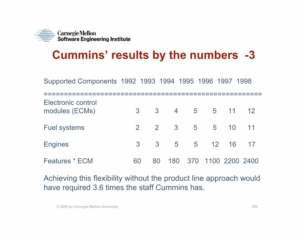
Achieved a product family capability with a breathtaking capacity for variation, or customization• 9 basic engine types• 4-18 cylinders• 3.9 - 164 liter displacement• 12 kinds of electronic control modules• 5 kinds of microprocessors• 10 kinds of fuel systems• diesel fuel or natural gas
Highly parameterized code. 300 parameters are available for setting by the customer after delivery.
© 2005 by Carnegie Mellon University 254
Cummins’ results by the numbers -1
• 20 product groups launched, which account for over 1000 separate engine applications
• 75% of all software, on average, comes from core assets
• Product cycle time has plummeted. Time to first engine start went from 250 person-months to a few person-months. One prototype was bulit over a weekend.
• Software quality is at an all-time high, which Cummins attributes to product line approach.
© 2005 by Carnegie Mellon University 255
Cummins’ results by the numbers -2
• Customer satisfaction is high. Productivity gains enables new features to be developed (more than 200 to date)
• Projects are more successful. Before product line approach, 3 of 10 were on track, 4 were failing, and 3 were on the edge. Now, 15 of 15 are on track.
• Widespread feeling that developers are more portable, and hence more valuable.
© 2005 by Carnegie Mellon University 256
Cummins’ results by the numbers -3
Supported Components 1992 1993 1994 1995 1996 1997 1998
======================================================Electronic control modules (ECMs) 3 3 4 5 5 11 12
Fuel systems 2 2 3 5 5 10 11
Engines 3 3 5 5 12 16 17
Features * ECM 60 80 180 370 1100 2200 2400
Achieving this flexibility without the product line approach would have required 3.6 times the staff Cummins has.
© 2005 by Carnegie Mellon University 257
Cummins’ results by the numbers -4
Today’s largest teams are smaller than yesterday’s smallest teams. Two-person teams are not unusual.
Cummins management has a history of embracing change, but carefully targeted change.• They estimate that process improvement alone has
brought a benefit/cost ratio of 2:1 to 3:1. • They estimate that the product line approach has
brought a benefit/cost ratio of 10:1.
Product line approach let them quickly enter and then dominate the industrial diesel engine market.
© 2005 by Carnegie Mellon University 258
Salion, Inc.A small organization: 21 people
Maker of software for suppliers who sell complex products via proposals.
• Salion Revenue Process Manager—helps suppliers manage opportunities. It contains a workflow engine and Web-based communication tools to help a supplier organization manage the collaboration of design and pricing. It keeps track of a proposal’s status and assists in the assembly of the final document.
• Salion Knowledge Manager—helps triage and analyze requests for proposals (RFPs), with decision support capabilities and analysis of bid performance, win/loss rates, and pricing. Helps choose the best candidates from among all the available opportunities. The Knowledge Manager uses historical information to prioritize opportunities and improve response rates.
• Salion Business Link—extends collaboration between the supplier and the customer, and between the supplier and subsuppliers.
© 2005 by Carnegie Mellon University 259
A specialized but important market“It should take us one day or less to turn a quote around. For some reason, it takes five weeks. This process is out of control.” —Director of Engineering, Tier 1 automotive supplier
“We recently rushed a late quote out the door that we thought we had priced with a ‘nice margin.’ In reality, the quote was for a part that we had been selling at twice the price we quoted. Luckily, our customer only asked for one year of retroactive rebates.” —Director of Sales, Tier 1 automotive supplier
© 2005 by Carnegie Mellon University 260
A specialized but important market“We just spent $100,000 on an opportunity that we had no chance of winning. We bid on the same business two years ago and our price was 50% too high. We have no way to capture or analyze our historical sales and bidding performance, so we make the same mistakes over and over.”—Tier 2 automotive supplier
“We spent $600,000 in overnight shipping costs last year.”—Tier 1 automotive supplier
© 2005 by Carnegie Mellon University 261
VariabilitiesCustomers run different combinations of products
Installation options: • Run on customer’s hardware (installed)• Run on Salion’s dedicated hardware (hosted) • Run on Salion’s shared hardware
Each customer will have a unique workflow, a unique set of input screens and other user-interface concerns, and a unique set of reports they want to generate.
Each customer will have unique “bulk load” requirements, involving the transformation of existing data and databases into forms compatible with Salion’s products.
An automotive industry trade group has defined a business-to-business transaction framework encompassing some 120 standard objects to be used to transfer information from organization to organization. Not every customer will want to make use of all 120 objects.
© 2005 by Carnegie Mellon University 262
How Salion builds its product lineFirst produced a “standard” product as its entry into the market.
That product formed the basis for Salion’s software product line and the basis for each new customer-specific product it fielded.
The standard product was more than an engineering model from which “real” systems were produced; it was also sold.
Typical product: 40 modules, 150K SLOC
© 2005 by Carnegie Mellon University 263
Customization vs. configurationSalion builds subsequent products by• customizing elements of the “standard” product.• configuring elements of the “standard” product.
Early on, Salion tried to make many elements configurable• Forms manager• Customized reports manager
Results were wasted effort, wrong guesses, and bloated software. Now, Salion customizes these aspects.
Tool support plays an important role in managing these variations: • 3,333 files for 3 products• 88 files represent variations
© 2005 by Carnegie Mellon University 264
Salion’s product line benefitsSeven developers produce and support sophisticated, highly secure, high-availability, COTS-intensive systems
As of report time, Salion had produced its 12th 30-day release, all of which were on schedule.
Building the standard product took 190 person-months. • Building the first customer product took just 15 person-
months with 97% reuse. • Building the second product took 30% less effort.
Salion’s approach gives it superb position to answer investors question “How are you going to scale?”• Normal answser: Re-write product to make robust, increase
development staff, bring on QA staff• Salion’s answer: Nothing. We can scale right now, as we
are.
© 2005 by Carnegie Mellon University 265
CelsiusTech: Ship System 2000A family of 55 ship systems
Integration test of 1-1.5 millionSLOC requires 1-2 people
Rehosting to a new platform/OStakes 3 months
Cost and schedule targets arepredictably met
Performance/distribution behaviorare known in advance
Customer satisfaction is highHardware-to-software cost ratio
changed from 35:65 to 80:20
© 2005 by Carnegie Mellon University 266
National Reconnaissance Office / Raytheon: Control Channel ToolkitGround-based spacecraft command and control systems
Increased quality by 10XIncremental build time
reduced from monthsto weeks
Software productivityincreased by 7X
Development time and costsdecreased by 50%
Decreased product risk
© 2005 by Carnegie Mellon University 267
Market Maker GmbH: MERGERInternet-based stock market software
Each product “uniquely”configured
Three days to put upa customized system
© 2005 by Carnegie Mellon University 268
Hewlett Packard
Printer systems• 2-7x cycle time improvement (some 10x)• Sample Project
–shipped 5x number of products–that were 4x as complex–and had 3x the number of features–with 4x products shipped/person
© 2005 by Carnegie Mellon University 269
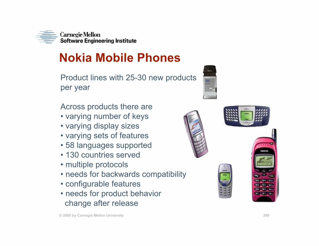
Nokia Mobile PhonesProduct lines with 25-30 new products per year
Across products there are• varying number of keys• varying display sizes• varying sets of features• 58 languages supported• 130 countries served• multiple protocols• needs for backwards compatibility• configurable features• needs for product behaviorchange after release
Sponsored by the U.S. Department of Defense© 2005 by Carnegie Mellon University
270
Pittsburgh, PA 15213-3890
1
Carnegie Mellon UniversitySoftware Engineering Institute
Software Product Lines: Software Product Lines: Introduction and Introduction and Basic ConceptsBasic Concepts
© 2005 by Carnegie Mellon University 271
Business Success Requires Software Prowess
Software pervades every sector. Software has become the bottom line for many organizations who never envisioned themselves in the software business.
© 2005 by Carnegie Mellon University 272
Universal Business Goals High quality
Quick time to market
Effective use of limited resources
Product alignment
Low cost production
Low cost maintenance
Mass customization
Mind share
improved efficiency
and productivity
© 2005 by Carnegie Mellon University 273
Software (System) Strategies
Process Improvement
Technology Innovation
Reuse
© 2005 by Carnegie Mellon University 274
Few Systems Are Unique
Most organizations produce families of similar systems, differentiated by features.
© 2005 by Carnegie Mellon University 275
Reuse History
1960’sSubroutines
1970’sModules
1980’sObjects
1990’sComponents
Focus was small-grained and opportunistic.Results fell short of expectations.
© 2005 by Carnegie Mellon University 276
Imagine Strategic Reuse
strategicreuse
business strategyand
technical strategy
© 2005 by Carnegie Mellon University 277
Reuse History: From Ad-Hoc to Systematic
1960’sSubroutines
1970’sModules
1980’sObjects
1990’sComponents
2000’sSoftware
Product Lines
© 2005 by Carnegie Mellon University 278
What is a Software Product Line?
A software product line is a set of software-intensive systems sharing a common, managed set of features that satisfy the specific needs of a particular market segment or mission and that are developed from a common set of core assets in a prescribed way.
© 2005 by Carnegie Mellon University 279
Software Product LinesMarket strategy/
Application domain
Architecture
Components
pertain to
share an
are built from
is satisfied by
used to structureProducts
COREASSETS
Product lines• take economic advantage of commonality • bound variability
© 2005 by Carnegie Mellon University 280
How Do Product Lines Help?Product lines amortize the investment in these and other core assets:
• requirements and requirements analysis•domain model•software architecture and design•performance engineering•documentation• test plans, test cases, and data•people: their knowledge and skills•processes, methods, and tools•budgets, schedules, and work plans•components
product lines = strategic reuse
earlier life-cyclereuse
more benefit
© 2005 by Carnegie Mellon University 281
Real World MotivationOrganizations use product line practices to:• achieve large scale productivity gains• improve time to market• maintain market presence• sustain unprecedented growth• compensate for an inability to hire• achieve systematic reuse goals• improve product quality• increase customer satisfaction• enable mass customization• get control of diverse product configurations
© 2005 by Carnegie Mellon University 282
The Key Concepts
Use of a common
asset basein production of a related
set of products
© 2005 by Carnegie Mellon University 283
The Key Concepts
Use of a common
asset basein production of a related
set of products
Architecture Production Plan Scope DefinitionBusiness Case
© 2005 by Carnegie Mellon University 284
Commercial ExamplesSuccessful software product lines have been built for families of• Mobile phones• Command and control ship systems• Ground-based spacecraft systems• Avionics systems• Pagers• Engine control systems• Billing systems• Web-based retail systems• Printers• Consumer electronic products• Acquisition management enterprise systems
© 2005 by Carnegie Mellon University 285
Organizational BenefitsImproved productivity
by as much as 10x
Decreased time to market (to field, to launch...)by as much as 10x
Decreased costby as much as 60%
Decreased labor needs by as much as 10X fewer software developers
Increased qualityby as much as 10X fewer defects
Sponsored by the U.S. Department of Defense© 2005 by Carnegie Mellon University
286
Pittsburgh, PA 15213-3890
1
Carnegie Mellon UniversitySoftware Engineering Institute
A Framework forA Framework forSoftware Product Line Software Product Line PracticePractice
© 2005 by Carnegie Mellon University 287
Product Line Practice
But there are universal essentialactivities and practices.
Contexts for productlines vary widely
• nature of products• nature of market ormission
• business goals• organizational infrastructure
• workforce distribution• process discipline• artifact maturity
© 2005 by Carnegie Mellon University 288
A Framework for Software Product Line PracticeThree essential activities…• core asset development• product development• management
…and the descriptions of the product line practice areas form a conceptual framework for software product line practice.
This framework is evolving based on the experience and information provided by the community.
Version 4.0: Software Product Lines: Practices and Patterns
Version 4.2: http://www.sei.cmu.edu/plp/framework.html
© 2005 by Carnegie Mellon University 289
Information Sources
Collaborations with customers
on actual product lines
Case studies, experience reports, and surveys
Workshops, and conferences
Applied research
© 2005 by Carnegie Mellon University 290
Three Essential Activities
Core AssetDevelopment
Management
ProductDevelopment
© 2005 by Carnegie Mellon University 291
The Nature of the Essential ActivitiesAll three activities are interrelated and highly iterative.
There is no “first” activity.- In some contexts, existing products are mined for core
assets.- In others, core assets may be developed or procured for
future use.
There is a strong feedback loop between the core assets and the products.
Strong management at multiple levels is needed throughout.
© 2005 by Carnegie Mellon University 292
ManagementManagement at multiple levels plays a critical role in the successful product line practice by
• achieving the right organizational structure• allocating resources• coordinating and supervising• providing training• rewarding employees appropriately• developing and communicating an acquisition strategy• managing external interfaces• creating and implementing a product line adoption plan
© 2005 by Carnegie Mellon University 293
Managing a Software Product Line Requires LeadershipA key role for a software product line manager is that of champion.
The champion must• set and maintain the vision• ensure appropriate goals and measures are in place• “sell” the product line up and down the chain• sustain morale• deflect potential derailments• solicit feedback and continuously improve the approach
© 2005 by Carnegie Mellon University 294
Different Approaches - 1Proactive: Develop the core assets first• Develop the scope first and use it as a “mission”
statement.• Products come to market quickly with minimum code-
writing.• Requires upfront investment and predictive knowledge.
Reactive: Start with one or more products • From these generate the product line core assets and
then future products; the scope evolves more dramatically.
• Much lower cost of entry• Architecture and other core assets must be robust,
extensible, and appropriate to future product line needs
© 2005 by Carnegie Mellon University 295
Different Approaches - 2Incremental: Develop in stages with the plan from the beginning to develop a product line.• Develop part of the core asset base, including the
architecture and some of the components.• Develop one or more products.• Develop part of the rest of the core asset base.• Develop more products.• Evolve more of the core asset base.• …..
© 2005 by Carnegie Mellon University 296
Driving the Essential Activities
Beneath the level of the essential activities are essential practices that fall into practice areas.
A practice area is a body of work or a collection of activities that an organization must master to successfully carry out the essential work of a product line.
© 2005 by Carnegie Mellon University 297
Product line experience yields important lessonsLessons in software engineering
• architectures for product lines• testing variable architectures and components• importance of having and capturing domain knowledge• managing variations• important of large, pre-integrated chunks
Lessons in technical/project management• importance of configuration management, and why it’s harder for product
lines• product line scoping: What’s in? What’s out?• Tool support for product lines
Lessons in organizational management.• People issues: how to bring about change, how to launch the effort• Organizational structure: Who builds the core assets?• Funding: How are the core assets paid for?• Interacting with the customer has whole new dimension
© 2005 by Carnegie Mellon University 298
Framework
Essential Activities
Practice Areas
SoftwareEngineering
TechnicalManagement
OrganizationalManagement
Architecture DefinitionArchitecture EvaluationComponent DevelopmentCOTS UtilizationMining Existing AssetsRequirements EngineeringSoftware System IntegrationTestingUnderstanding
Relevant Domains
Configuration ManagementData Collection, Metrics,
and TrackingMake/Buy/Mine/Commission
Analysis Process DefinitionScopingTechnical Planning Technical Risk ManagementTool Support
Building a Business CaseCustomer Interface ManagementImplementing an Acquisition
StrategyFundingLaunching and InstitutionalizingMarket AnalysisOperationsOrganizational PlanningOrganizational Risk ManagementStructuring the OrganizationTechnology ForecastingTraining
Core Asset Development
ProductDevelopment
Management
© 2005 by Carnegie Mellon University 299
Relationships among Categories of Practice Areas
SoftwareEngineeringPractice Areas
OrganizationalManagementPractice Areas
manage and support enable and orchestrate
TechnicalManagementPractice Areas
© 2005 by Carnegie Mellon University 300
Scoping
Scoping bounds a system or set of systems by defining those behaviors or aspects that are in and those that are out.
All system development involves scoping; there is no system for which everything is in.
In conventional development, scoping is usually done informally (if at all), as a prelude to the requirements engineering activity.
© 2005 by Carnegie Mellon University 301
Scoping: Aspects Peculiar to Product Lines - 1The overall goal is to define what’s in and what’s out.
Scope definition lets you determine if a proposed new product can be reasonably developed as part of the existing (or planned) product line.
We want to draw the boundary so the product line is profitable.
© 2005 by Carnegie Mellon University 302
Scoping: Aspects Peculiar to Product Lines - 2
Proper scoping is critical to a successful product line:
• If the scope is too limited, there will be too few products to justify the investment in the core assets.
• If the scope is too large, the core assets will need to be impossibly general.
• If the scope encompasses the wrong products, the product line will not succeed.
© 2005 by Carnegie Mellon University 303
Scoping: Aspects Peculiar to Product Lines - 3The scope starts out broad and very general.
In a product line of Web software• Browsers are definitely in.• Aircraft flight simulators are definitely out.• Email handlers are… well, we aren’t sure yet.
The scope grows more detailed as our knowledge increases and the product line matures.
Initially, many possible systems will be “on the cusp,” meaning their “in/out” decision must made on a case-by-case basis. That’s healthy.
© 2005 by Carnegie Mellon University 304
Scope precision increases as we learn more…up to a point.
a: space of all possible productsb: early, coarse-grained “in/out” decisionsc: product line scope with a healthy area of indecisiond: product line scope = product line requirements
If many products appear on the cusp over time, you need to reactively adjust the scope.
a. b. c. d.
© 2005 by Carnegie Mellon University 305
Proactively Adjusting the Scope -1
Companies highly skilled at product line engineering routinely adjust their scope to take advantage of opportunities that are in the market.
CelsiusTech• saw that air defense systems were just a short
distance away in the product space from ship systems
• was able to enter the air defense market quickly and effectively. Forty percent of its air defense system was complete on day one.
© 2005 by Carnegie Mellon University 306
Pro-actively Adjusting the Scope -2
Cummins, Inc.• developed a software product line for
automotive diesel engines• saw a lucrative underutilized market nearby in
industrial diesel engines• was able to quickly enter and dominate the
industrial diesel engine market Motorola• developed software product line for one-way
pagers• saw nearby market for two-way pagers and
was able to use the same product line architecture for both
© 2005 by Carnegie Mellon University 307
Key Themes Among Successful Product Lines
Sophistication in the domain
A legacy base from which to build
Architectural excellence
Process maturity
Management commitment
Capacity for introspection
© 2005 by Carnegie Mellon University 308
Based on Our Experience1. Product line business practices cannot be effected without
management commitment and involvement.2. Organization size doesn’t matter.3. Organizational culture plays a major role in adoption
success.4. Organizations need support: guidance, diagnostics, methods,
and tools.5. The lack of an architecture focus and/or talent can kill an
otherwise promising product line effort.6. Process discipline is critical.7. The community needs more quantitative data to support
product line adoption. 8. The cultural barriers and cost of adoption are major
impediments to widespread transition.9. Software product line practice is at the “chasm.” (in Geoffrey
Moore’s terms: Crossing the Chasm)
© 2005 by Carnegie Mellon University 309
The Time is RightRapidly maturing, increasingly sophisticated software development technologies including object technology, component technology, standardization of commercial middleware.
A global realization of the importance of architecture
A universal recognition of the need for process discipline.
Role models and case studies that are emerging in the literature and trade journals.
Conferences, workshops, and education programs that are now including product lines in the agenda.
Company and inter-company product line initiatives.
Rising recognition of the amazing cost/performance savings that are possible.
© 2005 by Carnegie Mellon University 310
Final Examination1. Produce four six-part quality attribute scenarios that
express (one each):- modifiability- performance- security- availability
2. Produce a list of tactics to support usability.
3. Product a quality attribute utility tree for a system you are familiar with. Try to include at least five quality attributes. For each one, decompose it into quality attribute concerns, and one or two scenarios each.