PK Technology Management System Requirements for Magnetic Flux Leakage Inspection
of Tank Floor Plates
Document Number: Release/Revision: Release/Revision Date PKT-NDE-MFE001 0 December 4, 2019 R0
CONTENT OWNER:
PK TECHNOLOGY QUALITY PROCESS COUNCIL
This Council has delegated responsibility, authority, and accountability to the Procurement Quality Integration Team (PQIT) to define, implement, sustain, and continuously improve PK Technology processes for quality management and
integrity.
All future revisions to this document shall be approved by the content owner prior to release.
1.1. This procedure defines requirements and specifies responsibilities for performing magnetic flux leakage testing of tank floor plates using the magnetic flux leakage method. It is applicable to relatively flat tank floor plates for top and bottom surface corrosion detection. The maximum floor plate thickness that can be inspected using this procedure is 0.500 inches.
1.2. Inspection personnel should be aware that the sensitivity of this technique depends upon the lift off of the sensors from the plate, which might vary at welds, plate edges, and the vertical edges of the floor
1.3. This Procedure and its applicable references, when used with Customer Specifications, shall define the requirements for the magnetic flux leakage inspection of tank floors of above ground storage tanks.
1.4. A change in a requirement listed in Table T-1623 of ASME Section V, Article 16 as an essential variable will necessitate a procedure revision and requalification of the sensitivity characteristics of this procedure.
2. METHOD OVERVIEW
2.1. MFL is a detection tool that uses very strong magnets mounted in a magnetic bridge that allows for saturation of the component under test. Any localized reduction in the thickness of the inspected material will result in a local leakage field at the surface of the component under test.
2.2. Sensors mounted along the bridge detect this leakage field. The strength of this leakage field is a function of the volume loss and is not a reliable indication of remaining wall loss.
2.3. MFL is to be used as a detection tool only. When the properly calibrated and functioning MFL equipment detects a leakage field, other NDE methods are to be used to determine the remaining wall thickness at the discontinuity site. Ultrasonic thickness is the primary method to “prove-up” these locations.
2.3.1. Ultrasonic thickness measurement shall be performed in accordance with PK Technology procedure PK-NDE-UT001, UT Thickness Procedure.
3. REFERENCED DOCUMENTS
3.1. The following documents are referenced by this procedure and the requirements of these documents are incorporated within this procedure:
3.1.3. API 653 – Tank Examination, Repair, Alteration, and Reconstruction
3.1.4. PKT-NDE-001 – PK Technology NDE Written Practice, PK Technology
3.1.5. MFE 2412 – Tank Floor Scanner “Operation and Maintenance Manual”
3.1.6. MFE 1212 - Tank Floor Scanner “Operation and Maintenance Manual”
3.1.7. MFE 2412 Mark II - Tank Floor Scanner “Operation and Maintenance Manual”
3.1.8. MFL 2000 - Tank Floor Scanner “Operation and Maintenance Manual
4. PERSONNEL
4.1. Personnel performing examinations based on the requirements listed in this procedure shall be certified in accordance PK Technology Written Practice PKT-NDE-001 to a Level II or Level III competency in MFL testing.
4.2. Personnel performing and evaluating magnetic flux leakage testing shall have a minimum Level II certification.
5. TEST EQUIPMENT AND MATERIALS
5.1. The equipment shall consist of magnets, sensor(s), and related electronic circuitry. A reference indicator, such as a ruled scale or linear array of illuminated LED lights should be used to provide a means of identifying the approximate lateral position of indications. The equipment may be designed for manual scanning or may be motor driven. Software on the unit or downloaded to a computer for analysis may be used to assist in the detection and characterization of discontinuities.
5.2. Test equipment used for magnetic flux leakage testing shall normally consist of the following:
Manufacturer Model
MFE Enterprises, Inc. MFE 1212 Mark II
MFE Enterprises, Inc. MFE Mark IV
MFE Enterprises, Inc. MFE PipeScan
MFE Enterprises, Inc. MFE HPX Wall Crawler
MFE Enterprises, Inc. MFE HandScan
5.3. Other comparable equipment may be used after sufficient specific operational training as approved by the Level III.
5.4. MFL equipment shall be calibrated annually or after each repair of major damage. If the equipment has not been used for over one year, the unit is subject to calibration prior to first use.
5.5. Reference Specimen
5.5.1. All MFE examinations shall have a reference plate or pipe section to ensure the equipment is performing in accordance with the manufacturer’s specifications prior to use.
5.5.2. The reference specimen for plate shall consist of a plate that is made from a material of the same nominal thickness, product form, and composition as the component to be tested.
5.5.2.1. The plate specimen shall have notches or other discontinuities manufactured into the bottom of the plate as shown in Figure 1, Reference Plate Dimensions.
5.5.3. The reference specimen for pipe or tubing shall consist of a pipe or tube that is made from a material of the same nominal pipe or tube sizes, product form, and composition as the component to be examined.
5.5.3.1. The pipe or tube specimen shall have notch discontinuities machined into the inside surfaces as shown in Figure 2, Reference Pipe or Tube Dimensions.
5.5.4. The depths and widths of the artificial discontinuities shall be similar to the sized and physical characteristics of discontinuities that are expected; the artificial discontinuities within the test plate or pipe or tube shall represent the minimum size of discontinuities to be located by the examination.
5.5.5. If non-magnetic coatings or temporary coverings will be present during the examination, the reference specimen shall be coated or covered with non-magnetic coatings or coverings representative of the maximum thickness to be encountered during testing.
5.5.5.1. Surface eddy current testing using an absolute probe for coating thickness may be used to determine coating thickness. If eddy current testing is to be performed, it shall be performed in accordance with PK Technology procedure.
5.5.5.2. Ultrasonic coating thickness testing may be used to determine coating thickness. If ultrasonic coating thickness testing is to be performed, it shall be performed in accordance with PK Technology procedure.
5.5.5.3. Dry mil coating thickness testing using equipment such as a ‘banana gauge’ may be used to determine coating thickness. If these types of tests to be performed, they shall be performed in accordance with PK Technology procedure.
5.6.1. The manufacturer’s verification procedure shall be conducted initially to ensure that the system is functioning properly. The functional check shall be made by scanning the reference specimen over the range of scanning speeds to be used during the examination. Equipment settings shall be documented.
5.7. Performance Confirmation
5.7.1. A functional check shall be conducted at the beginning and end of each examination, every 8 hours, or when the equipment has malfunctioned and been repaired. If it is determined that the equipment is not functioning properly, needed adjustments shall be made and all areas since the last acceptable performance check shall be reexamined.
6. TEST
6.1. Surface Preparation
6.1.1. The surface shall be adequately cleaned of loose debris, corrosion, oils, or other contaminants that may affect the test results or obscure the free movement of the scanner. The surface shall be suitably flat to minimize excessive changes in lift-off and vibration. If the surface contains undulations which will affect or inhibit inspection, these locations shall be documented and brought to the attention of the Level III and the Client. Any suitable cleaning method such as wiping, sweeping, scraping, buffing, sanding, blasting, or other may be used to ensure surface cleanliness depending upon type of contaminant being eliminated.
6.1.2. If the surface is coated and the coating is not removed, it shall be demonstrated that the MFL equipment can detect the specified imperfections through the maximum thickness of the coating as described above.
6.1.2.1. If a temporary sheet or coating is applied between the scanner and component under test to provide a smooth surface, for example, on a heavily pitted surface, it shall be demonstrated that the equipment can find the specified imperfections through the temporary sheet or coating.
6.2. Scanning Pattern
6.2.1. A scanning pattern shall be developed from drawings either provided by the Client or by field personnel based upon the size and configuration of the tank (or section thereof) to be inspected.
6.2.1.1. Where the scanning personnel skip a section of a scan or change the scan pattern, the changes or omissions shall be noted for additional examination or an explanation for the omission fully described in the final inspection report.
6.2.2. Generally, each floor plate to be inspected is given a number which is coordinated on a map of the floor using a paint marker or other permanent or semi-permanent means approved by the client.
6.2.3. Drawings shall show, in addition to the plates to be scanned, any appurtenances, striker plates, sump basins, and other areas that may preclude a complete inspection of the area.
6.3. Assembly of Equipment
Note: This section pertains primarily to the Mark IV floor scanner provided by MFE Enterprises. Refer to the manufacturer documentation for other specific models of scanners.
6.3.1. Remove the handle from the case and attach it to the bridge assembly while keeping the bridge on the keeper plate.
6.3.2. Attach all three cables to their respective location
6.3.3. Adjust the sensor bar to the #1 setting
6.3.4. Press the power button to turn the unit on
6.3.5. Select “Manual” tab in the software on the unit screen
6.3.6. Select “Configuration” screen and adjust the plate thickness to ½” and coating thickness to “0”.
6.3.6.1. The keeper plate is ½” thick and requires this change to perform a performance function test.
6.3.7. Scan the keeper plate to verify that a signal is obtained on all 12 channels
6.3.8. Select “Configuration” screen and adjust the plate / coating thickness to match conditions of the component.
6.3.9. Adjust Sensor Bar to the #3 setting
6.4. Performing Reference Plate Scan
6.4.1. Remove the scanner from the keeper plate and place onto the reference plate. Note the requirements of the reference plate stated above in regard to minimum size of discontinuity and nonconductive coating thickness.
6.4.2. Scan the reference plate in the longitudinal direction. Adjust the sensitivity amplitude to 40% full screen height. Scan the plate at the same speed to be used in the inspection
of the component. Several scans should be taken to account for the variance in travel speeds that may be encountered during the inspection.
6.4.2.1. A properly operating unit will show indications as full screen when crossing the 40% wall-loss indication on the reference plate. This indication should be visible on all channels.
6.4.2.2. The unit should show separate spikes which represent a simulated 40% wall loss discontinuity on the bottom side and a 3/16” through-wall hole on the reference plate. The sensor location of these indications will vary as to the location of the unit relative to the location of the equipment on the reference plate.
6.4.3. Note the location and sensitivity of the discontinuities. Adjust sensitivity as necessary by adjusting the sensor bar. Record the settings on the unit for inclusion into the final report.
6.4.4. Remove the scanner from reference plate and place the scanner on the component to be tested.
6.5. Scanning
6.5.1. Scanning shall be performed in accordance with the scanning pattern plan. Mark on the component the center of the bridge in both directions to allow for identification of the starting point of the scan. Usually, the scan will begin in the corner of the first plate to be scanned. Note that if the scanner is placed on the origin corner and the outer sensor is positioned adjacent to the fillet weld, a strip of approximately 1 ½” in width will not be inspected along the length of the plate.
6.5.2. Begin the scan within the scan speed parameters stipulated by the manufacturer for the type of scanner being used.
6.5.3. As the scan progresses, the display of the scanner will show indications of flux leakage fields along the display. When an indication is noted, stop the scan and move the scanner backwards and forward to ensure no changes in surface condition or buildup of material are affecting the test.
6.5.4. When the indication has been verified, while the equipment is in place over the leakage field, mark the affected sensors locations from the front of the sensor array and at the midpoint of the sensor array from the side of the unit.
6.5.5. Move the scanner backwards and circle the areas marked in the preceding step. These areas require other NDE to ‘prove-up’ the condition.
6.5.6. Continue the scan in accordance with the scanning pattern plan.
6.5.6.1. Where detection of linear imperfections is required, an additional scan, approximately perpendicular to the initial scan is required.
6.5.7. Document each indication marked for inclusion into the final report. The length, width, and sensitivity measurements are required for each leakage field.
6.6.1. An overlap of 2” (50 mm) minimum for adjacent placement of the scanner for scans in accordance with the scan pattern plan shall be used for each subsequent perpendicular scan.
6.7. Re-standardization for Different Wall Thickness Plates
6.7.1. If the plates comprising the inspection area are of differing thicknesses, the unit shall be re-standardized for each representative thickness.
6.7.1.1. Ultrasonic thickness measurement of each plate in each corner and an additional 6 locations for full plates and three locations for each partial plate, spread evenly throughout the plate, prior to scanning will show which plates have differing thicknesses.
6.7.1.2. These UT thickness readings shall be documented in regard to location, each reading, and an average of thicknesses found on each plate. This documentation shall be compiled into the final report if required by the Client.
7. EVALUATION
7.1. Unless otherwise specified by the Client or referencing Code Section, the area under test is acceptable when no leakage field is observed.
7.2. Unless otherwise agreed with the Client, all indications verified as having a remaining wall thickness less than 60% of the nominal value shall be recorded on the area map.
7.3. All proved-up areas that fail to meet Client rejection criteria shall be mapped using X (length dimension) and Y (width dimensions) in regard to location on the affected plate and size of the indication.
7.4. The technician shall complete the final report based solely on Client requirements.
8.1. All examinations shall be documented in the appropriate Client driven format.
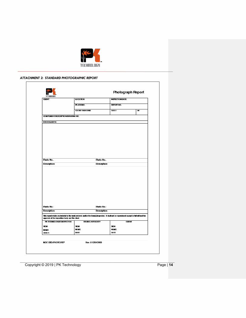
8.2. A picture of the appearance of leakage field locations within the scans area is helpful but not required if the Client does not allow for the use of photography devices.
8.2.1. If photographs are allowed and taken, a minimum of two shall be included on the report, the first showing a faraway view of the inspection area inclusive of the marked area of leakage field formation, and the second a close-up representation of the area of leakage field formation inclusive of the markings. A rule shall be used in all photographs.
8.3. The following information is required on all Magnetic Flux Leakage Test Reports:
8.3.1. Technicians name and certification level
8.3.2. Date and time of inspection and performance checks
8.3.3. Examination procedure used
8.3.4. Part identification and associated drawings
8.3.5. Material Type
8.3.6. MFL Equipment (manufacturer, size, model, serial number, calibration date)
8.3.7. Prove-up Equipment (manufacturer, model, serial number, calibration date
8.3.8. Ancillary Equipment (manufacturer, size, model, serial number, calibration date, as applicable)
8.3.9. Sensitivity level (minimum size of discontinuity detectable)
8.3.10. Location, depth, and type of all rejectable indications and prove-up method.


![Provincial Constituency Reference Map - District Peshawar · T uc l fa j n between ALHASAN [] ... PK - 9 PK - 5 PK - 11 PK - 4 PK - 3 PK - 2 PK - 1 Legend Districts Boundary Provincial](https://static.documents.pub/doc/80x56/5c01b81309d3f22b088d1121/provincial-constituency-reference-map-district-t-uc-l-fa-j-n-between-alhasan.jpg)


