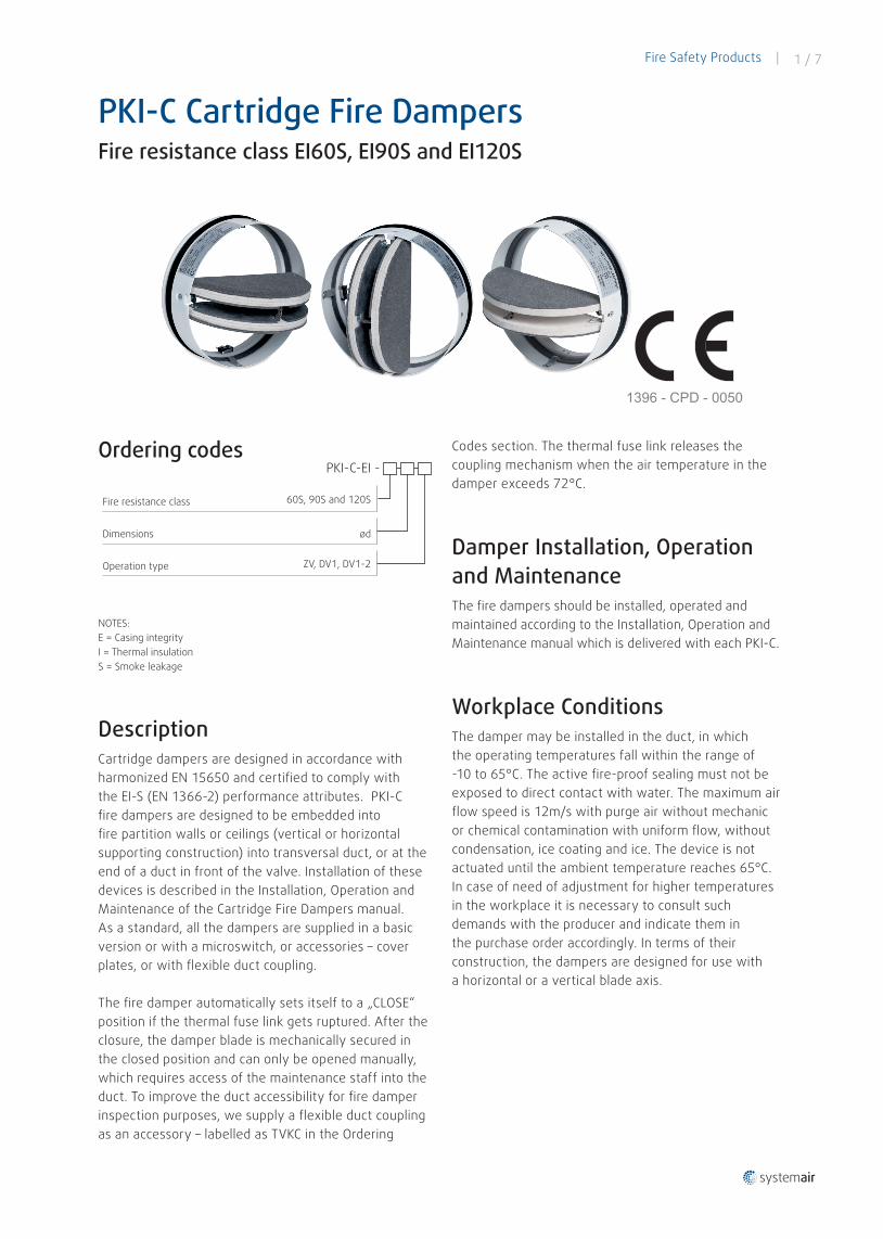
Fire Safety Products | 1 / 7 PKI-C Cartridge Fire Dampers Fire resistance class EI60S, EI90S and EI120S 1396 - CPD - 0050 Ordering codes PKI-C-EI - Fire resistance class Dimensions 60S, 90S and 120S ød Operation type ZV, DV1, DV1-2 NOTES: E = Casing integrity I = Thermal insulation S = Smoke leakage Description Cartridge dampers are designed in accordance with harmonized EN 15650 and certified to comply with the EI-S (EN 1366-2) performance attributes. PKI-C fire dampers are designed to be embedded into fire partition walls or ceilings (vertical or horizontal supporting construction) into transversal duct, or at the end of a duct in front of the valve. Installation of these devices is described in the Installation, Operation and Maintenance of the Cartridge Fire Dampers manual. As a standard, all the dampers are supplied in a basic version or with a microswitch, or accessories – cover plates, or with flexible duct coupling. The fire damper automatically sets itself to a „CLOSE“ position if the thermal fuse link gets ruptured. After the closure, the damper blade is mechanically secured in the closed position and can only be opened manually, which requires access of the maintenance staff into the duct. To improve the duct accessibility for fire damper inspection purposes, we supply a flexible duct coupling as an accessory – labelled as TVKC in the Ordering Codes section. The thermal fuse link releases the coupling mechanism when the air temperature in the damper exceeds 72°C. Damper Installation, Operation and Maintenance The fire dampers should be installed, operated and maintained according to the Installation, Operation and Maintenance manual which is delivered with each PKI-C. Workplace Conditions The damper may be installed in the duct, in which the operating temperatures fall within the range of -10 to 65°C. The active fire-proof sealing must not be exposed to direct contact with water. The maximum air flow speed is 12m/s with purge air without mechanic or chemical contamination with uniform flow, without condensation, ice coating and ice. The device is not actuated until the ambient temperature reaches 65°C. In case of need of adjustment for higher temperatures in the workplace it is necessary to consult such demands with the producer and indicate them in the purchase order accordingly. In terms of their construction, the dampers are designed for use with a horizontal or a vertical blade axis.
Transcript
Fire Safety Products | 1 / 7
PKI-C Cartridge Fire Dampers Fire resistance class EI60S, EI90S and EI120S
DescriptionCartridge dampers are designed in accordance with harmonized EN 15650 and certified to comply with the EI-S (EN 1366-2) performance attributes. PKI-C fire dampers are designed to be embedded into fire partition walls or ceilings (vertical or horizontal supporting construction) into transversal duct, or at the end of a duct in front of the valve. Installation of these devices is described in the Installation, Operation and Maintenance of the Cartridge Fire Dampers manual. As a standard, all the dampers are supplied in a basic version or with a microswitch, or accessories – cover plates, or with flexible duct coupling.
The fire damper automatically sets itself to a „CLOSE“ position if the thermal fuse link gets ruptured. After the closure, the damper blade is mechanically secured in the closed position and can only be opened manually, which requires access of the maintenance staff into the duct. To improve the duct accessibility for fire damper inspection purposes, we supply a flexible duct coupling as an accessory – labelled as TVKC in the Ordering
Codes section. The thermal fuse link releases the coupling mechanism when the air temperature in the damper exceeds 72°C.
Damper Installation, Operation and MaintenanceThe fire dampers should be installed, operated and maintained according to the Installation, Operation and Maintenance manual which is delivered with each PKI-C.
Workplace ConditionsThe damper may be installed in the duct, in which the operating temperatures fall within the range of -10 to 65°C. The active fire-proof sealing must not be exposed to direct contact with water. The maximum air flow speed is 12m/s with purge air without mechanic or chemical contamination with uniform flow, without condensation, ice coating and ice. The device is not actuated until the ambient temperature reaches 65°C. In case of need of adjustment for higher temperatures in the workplace it is necessary to consult such demands with the producer and indicate them in the purchase order accordingly. In terms of their construction, the dampers are designed for use with a horizontal or a vertical blade axis.
2 / 7 | Fire Safety Products
A complete set of four cover plates made of calcium-silicate boards (for usage during the installation please see the Installation, Operation and Maintenance manual). FOR DRY INSTALLATION COVER PLATES ARE OBLIGATORY!
Ordering Code - Cover Plates
PRC-ND
A flexible coupling for easier accessibility during inspections is placed directly behind the built-in duct to a side where the damper blades open.
NOTE: ND = Nominal dimension in table on page 4
Ordering Code - Flexible duct coupling
TVKC-ND
NOTE: ND = Nominal dimension in table on page 4
Transportation, Storage and Operating ConditionsIt is necessary to transport the dampers in boxes, by such means of transport that provide a cover. When handling during transportation and storage, the dampers must be protected against damage and weather conditions. The damper blades must be in the “CLOSE” position. It is recommended to store these products in a closed, dry area where the temperature falls within the range of -10°C to +50°C. The temperature during storage, transportation and operation must not exceed 65°C!
Material Used and DisposalThe product contains galvanized steel sheets, a calcium-silicate board, graphite fire-proof laminate, polyurethane foam, ethylene-propylene dry rubber, copper sheets, a special solder produced on a basis of Sn, Bi, Pb and powder paint. These are processed in compliance with the local regulations. The product does not contain any dangerous materials, with the exception of the solder’s miligram quantity that contains Pb.
WarrantyThe manufacturer provides a 24-month warranty period starting on the date of expedition, provided that the transportation, manipulation and operating conditions are met.
AppendixAny demands regarding deviations from the above mentioned technical specifications and conditions shall be discussed with the manufacturer. The manufacturer reserves the right to perform any modifications of the product without prior notice, provided that such changes have no effect on the quality and performance of the product. The most recent state of our products is available at www.imos-systemair.sk.
Damper Codes and TypesZV; Basic model with a spring return release driven by a thermal fuse link set to 72 °C.DV1; ZV + 1 microswitch 230V indicating the damper’s closed and open position (closed indication switched by one half of the blade, second half not indicated)DV1-2; ZV + 2 microswitches 230V indicating the damper’s closed and open position (indicated closing of both halfs of the blade)
Accessories
Fire Safety Products | 3 / 7
PKI-C-EI60S, -EI90S and -EI120SWe offer cartridge fire dampers with fire resistance class of 60, 90, 120 minutes for circular duct systems.
The cartridge fire dampers are CE certified according to EN 15650, have been tested in accordance with the EN 1366-2 regulation and classified in accordance with the EN13501-3 regulation:
PKI-C EI60S-ZV through DV1For dimensions ø 100 mm through ø 200 mm
PKI-C EI90S-ZV through DV1For dimensions ø 100 mm through ø 200 mm
Installation:Solid wall – wet and dryFlexible wall – wet and dryCeiling – wet
EI 90 (ve ho i ↔ o) S
PKI-C EI120S-ZV through DV1For dimensions ø 100 mm through ø 200 mm
Installation:Solid wall – wet and dryFlexible wall – wet and dryCeiling – wet
EI 120 (ve ho i ↔ o) S
All cartrige fire dampers PKI-C have CE certificate No.: 1396-CPD-0050.
4 / 7 | Fire Safety Products
3
7
1
2
4
6
5
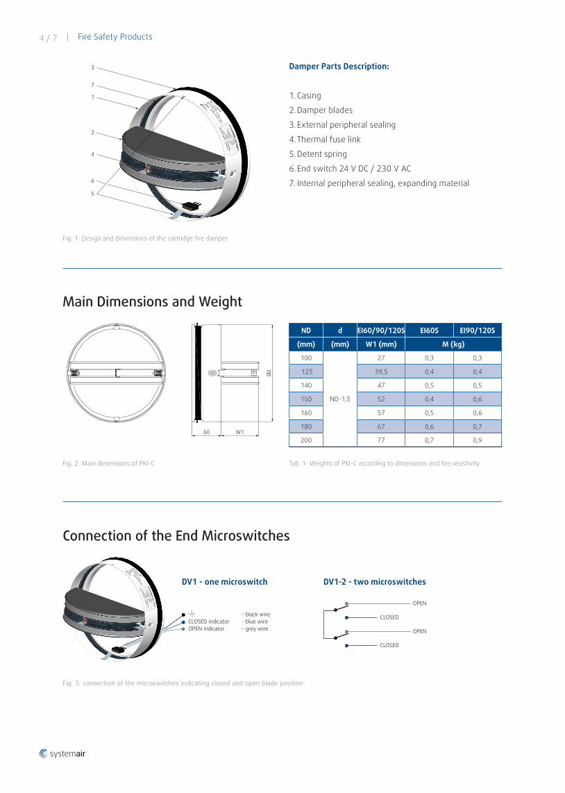
Damper Parts Description:
1. Casing
2. Damper blades
3. External peripheral sealing
4. Thermal fuse link
5. Detent spring
6. End switch 24 V DC / 230 V AC
7. Internal peripheral sealing, expanding material
Fig. 1: Design and dimensions of the cartridge fire damper
Main Dimensions and Weight
Ød
60 W1
ND d EI60/90/120S EI60S EI90/120S
(mm) (mm) W1 (mm) M (kg)
100
ND-1,5
27 0,3 0,3
125 39,5 0,4 0,4
140 47 0,5 0,5
150 52 0,4 0,6
160 57 0,5 0,6
180 67 0,6 0,7
200 77 0,7 0,9
Connection of the End Microswitches
- black wireCLOSED indicator - blue wireOPEN indicator - grey wire
DV1 - one microswitch
CLOSED
OPEN
CLOSED
OPEN
DV1-2 - two microswitches
Tab. 1: Weights of PKI-C according to dimensions and fire resistivityFig. 2: Main dimensions of PKI-C
Fig. 3: connection of the microswitches indicating closed and open blade position
Fire Safety Products | 5 / 7
Adjustment of the Blade into the Operating Position
2. Open the halfs of the blade into a parallel position
3. Klick on the thermal fuse
Pressure Loss and Noise
1. Press both detent springs
1,0
10,0
100,0
Δp (
Pa)
v (m/s)
30 dB(A)
35 dB(A)
40 dB(A)
45 dB(A)
9080706050
40
30
20
98765
4
3
2
2 3 4 5 6 7 8 9 101
Fig. 4: setup of the blade into open position
Diagram 1: Pressure loss and noise
6 / 7 | Fire Safety Products
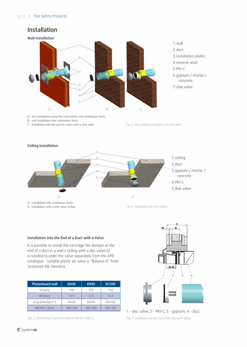
1. wall
2. duct
3. installation plates
4. mineral wool
5. PKI-C
6. gypsum / mortar / concrete
7. disk valve
A – dry installation using the cover plates into continuous ductsB – wet installation into continuous ductsC – installation into the end of a duct with a disk valve
1
2
2
3
4
5
6
7
A B C
Ceiling Installation
1. ceiling
2. duct
3. gypsum / mortar / concrete
4. PKI-C
5. disk valve
1
2
3
4
5
D E
D – installation into continuous ductsE – installation with a disk valve orifice
Installation Into the End of a Duct with a Valve
It is possible to install the cartridge fire damper at theend of a duct in a wall / ceiling with a disc valve (itis needed to order the valve separately from the APDcatalogue - suitable plastic air valve is “Balance-E” from Systemair AB, Sweden)