61
PLACE FOR TITLE AUTHORS Vibration Analysis for Turbomachinery Ed Wilcox Chevron Energy Technology Company Houston, TX

PLACE FOR TITLEAUTHORSVibration Analysis for Turbomachinery
Ed WilcoxChevron Energy Technology Company
Houston, TX
Content
• Differences between vibration analysis of general purpose and turbomachinery
• Measurement– Proximity Probes
• Plots w/ case studies– Bode/Polar
– Spectrums – Cascade/Waterfall
– Orbit
– Shaft Centerline

General Purpose vs Turbomachinery
• General purpose machinery – pumps, motors, fans, typical operates below 1st critical, most troubleshooting accomplished using spectrums
• Turbomachinery – compressors, turbines, tilt-pad bearings, etc.., normally operates above 1st critical, requires analysis of many different plots to determine root cause of vibration issues.

MeasurementProximity Probes
• Measures actual shaft displacement
• Includes probe, extension cable, and proximitor which are a matched set
• Limited to < 1000-1200 hz
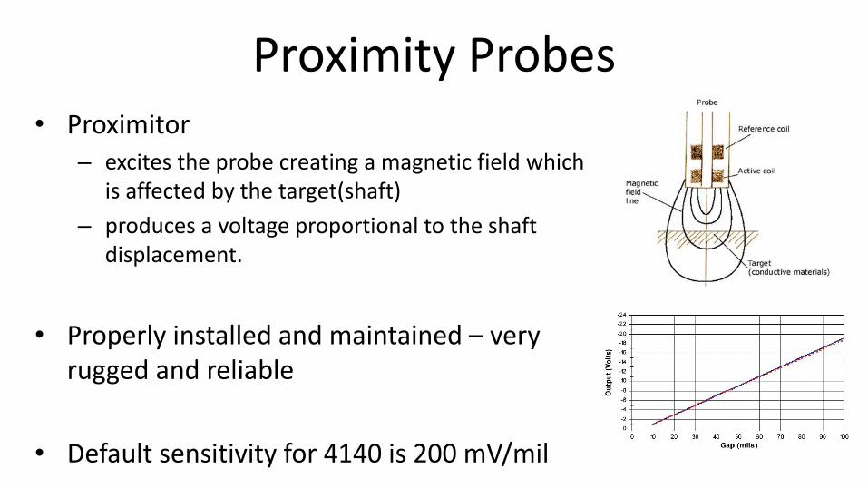
Proximity Probes• Proximitor
– excites the probe creating a magnetic field which is affected by the target(shaft)
– produces a voltage proportional to the shaft displacement.
• Properly installed and maintained – very rugged and reliable
• Default sensitivity for 4140 is 200 mV/mil

Proximity Probe Output
• DC component represents shaft position
• AC component represents shaft vibration
DC = -10 volts
pk-pk
displacement
AC= 4 volts

Proximity Probes - Pitfalls• Target surface condition – scratches show up as
vibration
Proximity Probes - Pitfalls
• Magnetism – if a residual magnetism exists in the shaft or target, this will affect the probes
• Incorrect target material – coatings and/or non-ferrous materials will affect probe readings
• Wrong extension cable – proximitor, extension cable, and probe are a matched set (total lengths of 1, 5, or 9 m)

Proximity Probes - Pitfalls
• Rotor kit with correct proximitor, no extension cable

Proximity Probes - Pitfalls
• Same rotor kit, probe, proximitor, added 4 m extension cable
Proximity Probes - Pitfalls
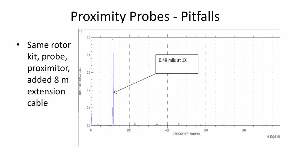
• Same rotor kit, probe, proximitor, added 8 m extension cable

Bode Plots• Vibration amplitude vs
speed
• Critical shown by peak amplitude and phase change
• Uses– Determine natural
frequencies (modes)
– Indication of system damping
– Tune rotordynamic models

Bode Plot - Compensation
• Runout Vector – probe output at slow speed (<500 rpm), not vibration
• Compensated – run-out vector subtracted from raw reading
Compensated
1x
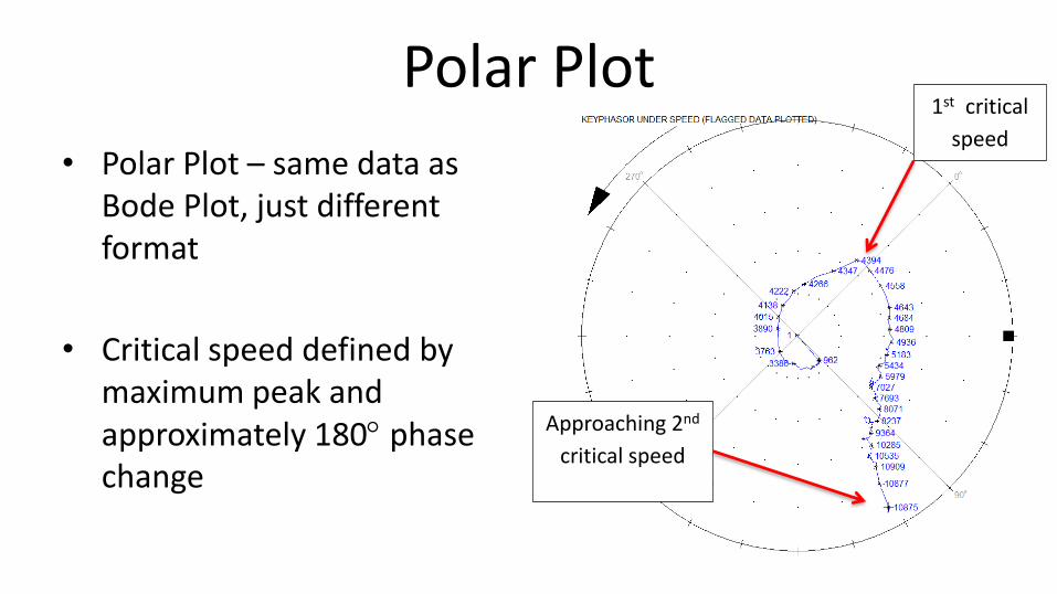
Polar Plot
• Polar Plot – same data as Bode Plot, just different format
• Critical speed defined by maximum peak and approximately 180 phase change
1st critical
speed
Approaching 2nd
critical speed

Bode Plots – Resonance Detection
• 4 pole generator FAT
• Identified 1st critical only 400 rpm above running speed during overspeed test..
• Problem could occur if natural frequency drops close to running speed.

Amplification Factor
• AF is a good ND indication of damping present in system
– 𝐴𝐹 =∝1
𝑑𝑎𝑚𝑝𝑖𝑛𝑔
• ½ power method
• Change in AF can indicate change in the hydrodynamic bearings since they provide a lot of the damping in the system
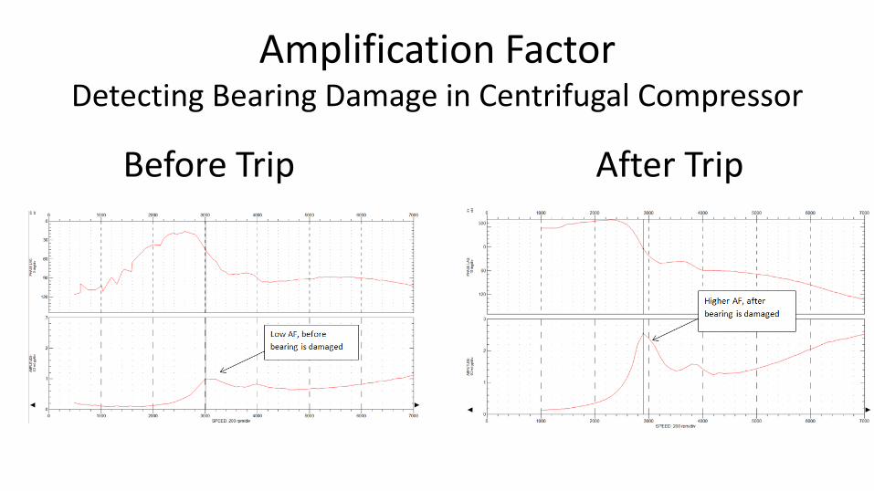
Amplification FactorDetecting Bearing Damage in Centrifugal Compressor
Before Trip After Trip

Amplification FactorDetecting Bearing Damage
• Bearing showed evidence of loss of lube
• Clearance was 30 % above maximum
• Increase in clearance reduces damping and increases AF
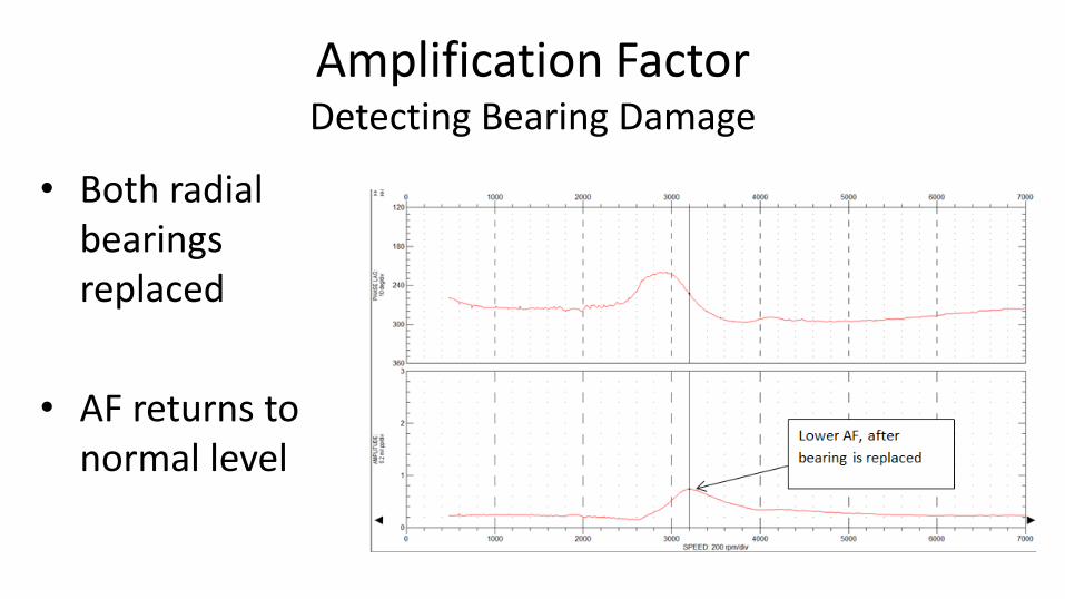
Amplification FactorDetecting Bearing Damage
• Both radial bearings replaced
• AF returns to normal level
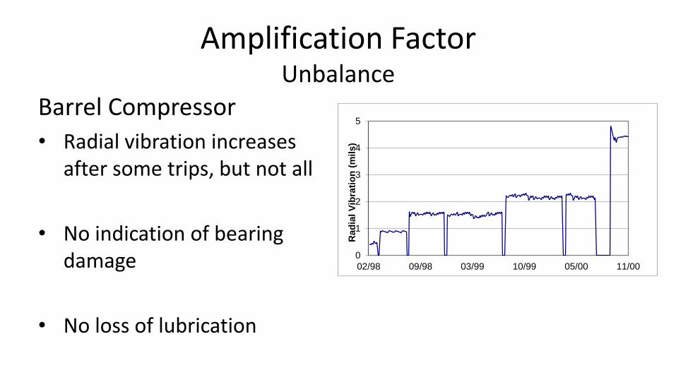
Amplification FactorUnbalance
Barrel Compressor
• Radial vibration increases after some trips, but not all
• No indication of bearing damage
• No loss of lubrication
0
1
2
3
4
5
02/98 09/98 03/99 10/99 05/00 11/00
Rad
ial
Vib
rati
on
(m
ils)

Amplification FactorUnbalance
FAT Test
0
0.2
0.4
0.6
0.8
1
0 2000 4000 6000 8000 10000
Ove
rall R
ad
ial
Vib
rati
on
(m
ils
)
Speed (rpm)
AF=4.5 at OEM shop test
2 Years later
AF~5

Amplification FactorUnbalance
• After extended plant outage, compressor restarts with high radial vibration
• Rotor inspection shows large amount of fouling, cleaned returned to service
AF ~ 5-5.5
Tune Rotordynamic Models
• Measured natural modes used to “tune” rotordynamic models to better represent actual conditions

High Speed Steam Turbine
• 8,000 hp steam turbine, driving ethylene refrigeration compressor
• Turbine normally operates between 8,500-9,500 rpm
• High radial vibration on outboard end during overspeed trip testing.
Steamturbine
Ethylene compressor

Tune Rotor Models
• High radial vibration on steam turbine outboard end during overspeed trip testing, 10,700 rpm
• Turbine normally operated below 10,000 rpm with vibration < 1 mil
Tune Rotor Models
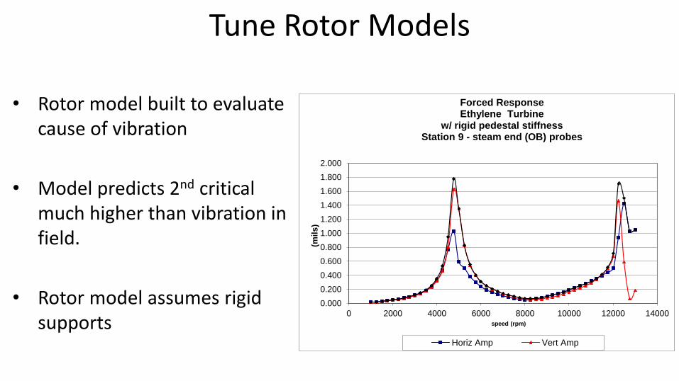
• Rotor model built to evaluate cause of vibration
• Model predicts 2nd critical much higher than vibration in field.
• Rotor model assumes rigid supports
0.000
0.200
0.400
0.600
0.800
1.000
1.200
1.400
1.600
1.800
2.000
0 2000 4000 6000 8000 10000 12000 14000(m
ils
)speed (rpm)
Forced ResponseEthylene Turbine
w/ rigid pedestal stiffnessStation 9 - steam end (OB) probes
Horiz Amp Vert Amp

Tune Rotor Models
• Turbine outboard bearing has a “wobble foot” design to allow for thermal expansion
• Bearing housing support stiffness added to rotor model
ROTOR DRWG
Ethylene turbine
-15
-10
-5
0
5
10
15
-10 0 10 20 30 40 50 60 70 80 90
Axial Location
Total rotor weight= 781.74 lbs
Rotor length= 80.6795 in
Bearing Span= 53.87949
Static Bearing Loads
sta 8= 392.74 lbs
sta 22= 389 lbs
CG is 43.18 in from sta 1
hsghsg

Tune Rotor Models
• Adding bearing support stiffness to model lowers predicted 2nd critical
• Turbine OB bearing clearance was shimmed to 0.0005 in below minimum design
Forced ResponseEthylene turbine
Station 9 -OB probes
0.000
0.500
1.000
1.500
2.000
2.500
3.000
3.500
4.000
4.500
0 2000 4000 6000 8000 10000 12000 14000speed (rpm)
(mil
s)
Horiz Amp Vert Amp Major Axis Amp
2nd critical much closer
to measured response

High Speed Steam TurbineAfter bearing clearance change
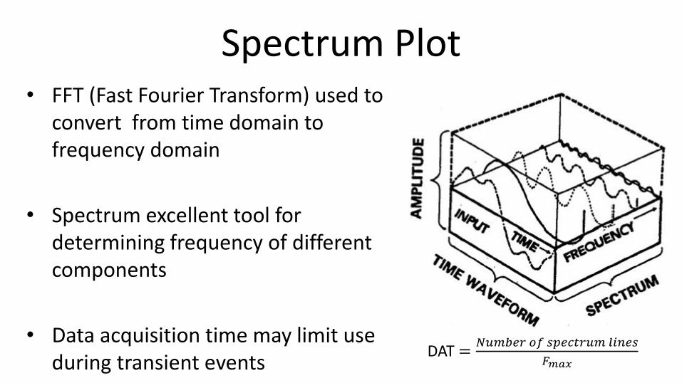
Spectrum Plot• FFT (Fast Fourier Transform) used to
convert from time domain to frequency domain
• Spectrum excellent tool for determining frequency of different components
• Data acquisition time may limit use during transient events
DAT =𝑁𝑢𝑚𝑏𝑒𝑟 𝑜𝑓 𝑠𝑝𝑒𝑐𝑡𝑟𝑢𝑚 𝑙𝑖𝑛𝑒𝑠
𝐹𝑚𝑎𝑥
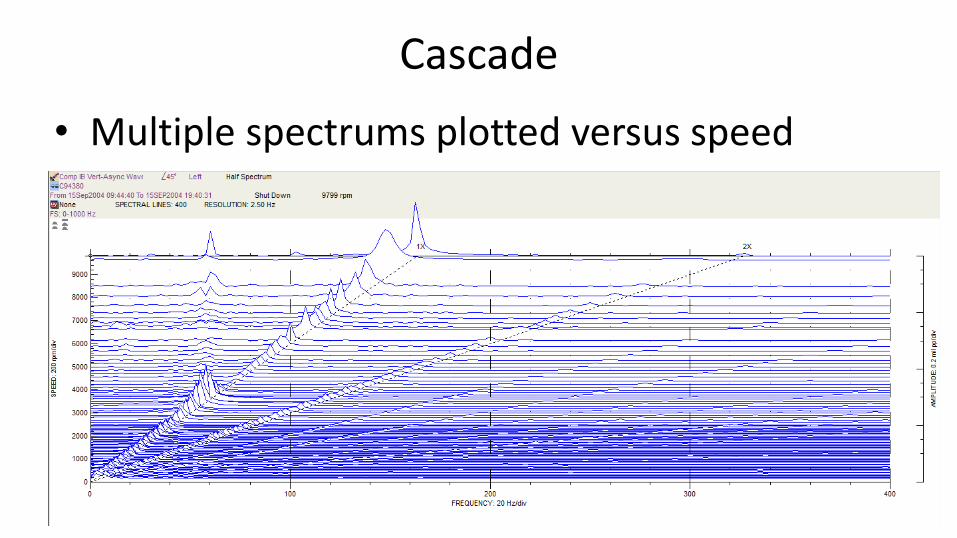
Cascade
• Multiple spectrums plotted versus speed

Waterfall Plot• Multiple spectrums plotted versus time

Centrifugal Compressor w/ sub-synchronous instability
• Single casing, straight through
• Propylene export
• P1=30, P2=300 psig
• 5 pad, LBP bearings
• Dry gas seals
Gear
4000 hp3550 rpm motor 5 impeller,
9750 rpm
• Balance drum has rotating labyrinth and abraidable stationary
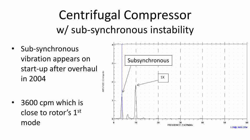
Centrifugal Compressor w/ sub-synchronous instability
• Sub-synchronous vibration appears on start-up after overhaul in 2004
• 3600 cpm which is close to rotor’s 1st
mode
Subsynchronous

Centrifugal Compressor InstabilitySub-synchronous vibration
• Cascade plot shows subsynchronous peak appears only at higher speed
• Indicates that sub-synchronous could be exciting 1st critical

Centrifugal Compressor InstabilitySub-synchronous vibration
• Vibration tracked closely with discharge pressure

Centrifugal Compressor InstabilityBalance Drum Seal History
• Abradable balance drum seal had failed every 3-4 years since installation in 1991
• End gap between seal was increased after 2001 failure
• Latest (2004) overhaul to inspect seal to see if failure imminent
2001
1997
1994

Centrifugal Compressor InstabilityBalance Drum Seal
• End gap clearance increased
further during latest overhaul (2004) due to multiple failures in past
• Rotor model built to evaluate problem Abradable
stationary seal
Rotating
labyrinth on
balance drum

Stability Analysis
-0.04
-0.02
0
0.02
0.04
0.06
250 270 290 310 330 350 370 390
Discharge Pressure (psig)
Log Dec versus Discharge Pressure
P2=300 psig
• Compressor has low margin of stability

Centrifugal Compressor Instability• Balance drum seal was root
cause but difficult to replace
• Bearing optimized by increasing L/D, changed configuration to LOP, lowered preload
• Calculated 1st mode log dec increased from 0.05 to 0.2
Damped Mode Shape Plot
Propylene Export Compressor
f= 3206.78 cpm
ld= 0.2
N= 9777 rpm
Drive End

Centrifugal Compressor InstabilityAt-speed testing
Original LBP bearing Optimized LOP bearing

Centrifugal Compressor InstabilityBearing Change Results

Shaft Orbit
• Orbit shows rotor procession in bearing
• Created by plotting Y vs X time waveform
• Blank-bright sequence shows rotation

Shaft Centerline
• Similar to orbit, but DC portion used to show center of shaft orbit
• Excellent for showing rubs, excessive clearance, mis-alignment
• Must be careful with transient thermal effects
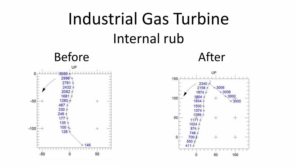
Industrial Gas TurbineInternal rub
Before After

Industrial Gas TurbineInternal rub – progression
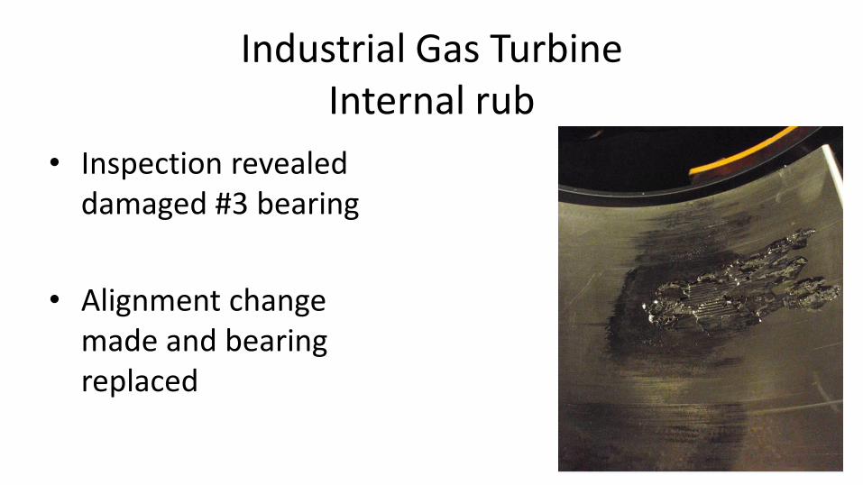
Industrial Gas TurbineInternal rub
• Inspection revealed damaged #3 bearing
• Alignment change made and bearing replaced

Shaft CenterlineInsufficient bearing clearance
Compressor OB Compressor IB

Shaft Centerline Plot
• IB Bearing clearance was too low
• Pads should never be scored in top half of bearing on a beam style compressor
UPPER
LOWER
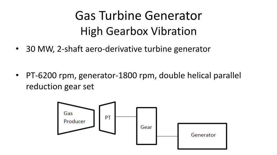
Gas Turbine GeneratorHigh Gearbox Vibration
• 30 MW, 2-shaft aero-derivative turbine generator
• PT-6200 rpm, generator-1800 rpm, double helical parallel reduction gear set

Gas Turbine GeneratorHigh Gearbox Vibration
• High vibration occurs on pinion during open breaker test (FAT), when load is rejected
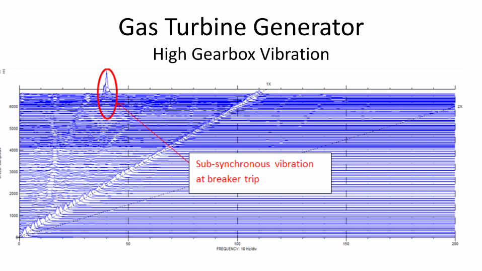
Gas Turbine GeneratorHigh Gearbox Vibration
Gas Turbine GeneratorHigh Gearbox Vibration
• Initial hypothesis was a torsional resonance excited by the open breaker sequence.
• Torsional vibration was found to be very low, no torsional critical at 40 hz.

Parallel Gearbox (speed reduction)
• Gear radial load pushes down on bull-gear and up on pinion
• Gear load more than enough to lift weight of pinion and keep it stable (no whirl)
• Pressure dam bearing in lower half of pinion used to load pinion up at low power conditions

Gas Turbine GeneratorHigh Gearbox Vibration
• Shaft centerline plot shows effects of:– changes in load
– pressure dam bearings

High Gearbox Vibration
• Speed trends show that open breaker test causes inertia of generator to act as a brake

Pinion Bearing Modifications
• Open breaker reverses gear load and pushes down on pinion
• Pressure dam in lower half of pinion bearing rotated to 20 so that it is opposite gear load during reversal

Gas Turbine GeneratorHigh Gearbox Vibration
• Note that pinion comes almost straight down after pressure dam re-located.
• Load changes still present in shaft centerline

Gas Turbine GeneratorHigh Gearbox Vibration
• Bearing modifications minimize sub-synchronous during open breaker test

Conclusions
• Complexity of turbomachinery normally requires the use of multiple plots to properly diagnosis vibration problems.
• Understanding of rotordynamics and the ability to build rotor models key to designing correct solutions.

Questions?


