PLA FOR A COMPUTER-BASED CONSULTANT SYSTEM Ni Is J. Ni lsson J. Agin B. G. Deutsch R. Fikes E. D. Sacerdoti J. M. Tenenbaum Artificial Intelligence Center Technical Note 94 May 1974 The work reported herein was sponsored by the Advanced Research Projects Agency of the Department of Defense under Contract DAHC04-72-C-008 with the U. S. Army Research Office.
Transcript
PLA FOR A COMPUTER-BASED CONSULTANT SYSTEM
Ni Is J. Ni lsson
J. Agin
B. G. Deutsch
R. Fikes
E. D. Sacerdoti
J. M. Tenenbaum
Artificial Intelligence CenterTechnical Note 94
May 1974
The work reported herein was sponsored by the Advanced Research ProjectsAgency of the Department of Defense under Contract DAHC04-72-C-008 withthe U. S. Army Research Office.
,",
CONTENTS
ABS TRACT
LIST OF ILLUSTRATIONS
LI ST OF TABLES
I NTRODUCTI ON
Project Goal
Applications
Demonstration System
Overview of Report
II DESCRIPTION OF DEMONSTRATION SYSTEMDomain Selection
Scientific Value DoD Relevance
Amenabi Ii ty to Sound ManagementExtendibili ty and Generali ty Experimental Convenience
Compati bi Ii ty wi th Speech-Understanding Research
Description of the Domain
Apprentice Tasks
Capabi Ii ties of the Demonstration System
D i a logSpeci fic Capabi Ii ties
I I I RESEARCH PROBLEMSPlanning and Execution Moni toringVi sion .
Natural Language
Discourse Semantics
Pragmatics and Model Interaction
Description, Generation, and Comprehension
iii
I II RESEARCH PROBLEMS (Continued)
System Integration
IV PROJECT PLA
APPEND I CE S
Phasing
The Phase I System
Organization
Research Tasks
Planning and Execution Moni toring (Leader: RichardF i ke s )
Vision Research (Leader: J. M. Tenenbaum) . Natural-Language Investigation (Leader: BarbaraDe u t s ch ) .
DESCRIPTION OF A SIMPLE AIR COMPRESSOR
ANALYSIS OF AIR COMPRESSOR CHECKOUT TASK
REFERENCES
ABSTRACT
Thi s report describes the goals and plans for a five-year proj ect
to develop a computer-based system that wi 11 serve as an expert consul-
tant to a human apprentice. Together, the system and the apprentice
will be engaged in a task of "checking out" and repairing electro-
mechanical equipment in a workstation domain.
We have specified the capabilities of a system that we think
achievable in five years, and we have identified the major research
problem areas involved. These include modeling and representation, auto-
matic planning and problem solving, machine vision, natural-language
communication, and system integration.
The demonstration system will gi ve the human apprentice advice
about how to diagnose equipment faults, how to repair them, and how to
assemble and disassemble equipment. I t will also gi ve instructionsabout workstation procedures and information about such matters as the
names of components and uses of tools. The level of detail of this ad-
vice and information wi 11 be automatically tai lored to the indi vidual
needs of the apprentice , who will be able ei ther to ask specific questionsor seek general guidance. An important means of communication will bethrough natural language. The system will have the abili ty to under-stand continuous speech about the domain of interest.
Another important perceptual channel will be computer-based vision.The vi sual subsystem wi 11 be able to identi fy equipment component s, in-spect assemblies, and generally moni tor progress at the workstation.
The demonstration system itself will serve to illustrate the feasi-
bility of applying the constituent computer technology to problems of
iii
equipment operation, maintenance, and repair; to remote site and vehicle
support; and to similar applications.
We are proposing to divide the project into two consecutive phases.
Phase I , to last three years, wi 11 be concluded by demonstrating a scaled-
down system. Thi s system wi 11 contain many of the planning and vi sual
abili ties of the proposed final system, but it will not have a continuousspeech-understanding component; it will operate at a rate slower than
real time, and its domain of experti se will be limited to a single version
of a simple air compressor. During this first phase, we will be conducting
the research necessary for constructing such systems, testing out various
approaches, and further elaborating our plans for the final demonstration
system. During Phase II , the last two years, we will use the results of
the first demonstration to adjust our research and design strategies.For the final demonstration system, we wi 11 relax the restrictions of
Phase I. The system will have become expert about a class of equipment
including pumps, motors, and air compressors, and it will accept spoken
natural language as input. Our report gives full details on the phasing
of the project and specific plans for the research to be conducted.
ILLUSTRATIONS
Proposed Workstation
An Ai r Compressor
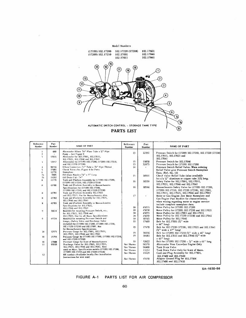
A-I Part s List Automatic Switch Control Storage Tank Type
Parts List Pump Unit
TABLES
Workstation Components
INTRODUCTION
Project Goal
This report describes a research program the goal of which is to
develop a computer system that can serve as an expert consultant to a
human about a domain of kpowledge. As just one example, such a system
could advi se and guide a human apprentice about the operation, assembly,fault diagnosis , and repair of electromechanical equipment.
Consider the following excerpt from a dialog between an expert and
an apprentice during checkout of a small air compressor:
Expert: Have you checked the belt?Apprentice: What belt?E: I am pointing at the belt housing frame. The belt is
inside. To check it , you will have to remove the belthousing cover.
A: Where ' s that?
E: It' s attached to the back of the belt housing frame byten screws.
A: O.K. I have the cover off. The belt is hanging looselyaround the wo pulleys.
E: Please show me the belt. Thank you. Yes, the belt needsto be replaced.
A: I have a new one here. I' ll replace it.E: O. K , but first you should check some other things.
The goal of this project , simply stated, is to produce a computer
system that can fi 11 the role of an expert such as the one in the abovedialog both in knowledge of the domain and in abili ty to communicatethat knowledge. Later in this report , we shall analyze a more extensive
dialog to extract the research problems confronting the development of a
computer-based expert. We can state briefly here that the major problems
are involved wi th modeling and representational techniques, natural-
language communication, computer perception of vi sual images, automatic
planning and problem solving, and system integration.
Applications
Why is it important to develop computer-based consultant systems?
First of all, even a trained person has frequent need of consulting man-uals, references, and other human experts, so there is a definite need
for readily vailable expert knowledge. In both industry and the mili-
tary, equipment maintenance and training of maintenance people represents
a large budget item. Any technology that can reduce these expenditures
and lessen the need for utilizing scarce human experts will obviously be
greatly in demand. We are also convinced that the need for consultation
cannot be satisfied merely by wri ting more and better manuals. A sophis-
ticated computer system seems to us essential. We might cite SQme advan-
tages that such a computer system would have over wri tten (or prerecorded
voice) manuals. I t would be:
More closely adapted to the particular user and hi s needs(e. g. , the level of detai 1 can be changed dynamica lly to
match the expertise of the user).
Richer in human interface possibilities (e. , speech com-
munication in both directions).More easily modifiable.
Able to reproduce up-to-date copies of the current versions
easily, and to distribute them via computer nets.
Able to monitor the progress of the user at his task.
Able, as an active partner, to take the initiative whenit is appropriate.
Computer-based consultant ' systems would be useful in several appli-
cation areas. The following come easily to mind.
Systems that are expert in equipment design, operationmaintenance, assembly and/or repair.Systems that are expert in the operation and procedures
of specialized remote sites and vehicles, such as
- Radar stations
- Submarines and other naval ships
- Manned sate IIi tes- Aircraft
- Polar stations.Medical systems:
- Diagnosing
- Surgical consulting.
Air traffic control systems.
Management support systems. Mi Ii tary command and control systems.
Legal reference systems.
Office information systems.
Computer programmer s ad vi ser .
In these applications, the emphasis would be on building systems
that can converse naturally wi th humans and aid them by providing advice
answering queries, and so on.
Demonstration System
Before large-scale computer-based consultant systems for these appli-
cations will be feasible, there are a number of research problems that
must be solved. We are proposing here a highly focused fi ve-year research
An ongoing SRI project (Contract N00014-71-C-0210) sponsored by the
Office of Naval Research i s already beginning to make use of arti-ficial intelligence (AI) techniques in research on large-scale com-puter-based management systems for naval repair operations. (Ref-erences are Ii sted at the end of thi s report).
project designed to attack these problems. At the end of this period
specifically 1 April 1978, we plan to demonstrate a model computer con-
sultant system. This demonstration system will show the feasibility ofour solutions to the major research problems and will serve as a proto-
type from which actual applications systems can be developed.
Overview of Report
In the next section we will describe the domain of expertise selected
for the five-year demonstration system and the criteria used in the selec-
tion of that domain. Next , we shall describe the planned capabilities of
the demonstration system and di scuss the major research problems that
arise in attempts to meet them. Finally, we shall present our plan forattacking these research problems and for integrating the results into
the demonstration system itself.
I I DESCRIPTION OF DEMONSTRATION SYSTEM
Domain Selection
The domain we have selected for the demonstration system is a work-
station in which various types of electromechanical devices are to be
checked out and repaired by a human apprentice. The system wi 11 be able
to answer queries from the apprentice about the properties and purposes
of tools, subassemblies, and parts. I t wi 11 be able to provide advice
and instructions on how to assemble, di sassemble, operate, troubleshoot
and repair the devi ces being maintained at the workstation. Al though weexpect the demonstration system to be competent wi th a range of electro-
mechanical devices, we shall concentrate attention at the start specifi-
cally on an air compressor Such a choice allows us , even at the beginning,
to deal with a reasonably complex system consi sting of an electric motor
a pump, air storage tank and lines, and a feedback control device.
In this section we will describe the criteria we used in selecting
repair of electromechanical devices as the domain for our project , and
then we will gi ve a more detailed description of the workstation and the
capabi Ii ties that we expect our demonstration system to have.
We used six general cri teria in evaluating possible domains.
Scientific value
DoD relevance
Amenabi Ii ty to sound management
Extendability and generality
Experimental convenience
Compatabili ty wi th speech-understanding research.
Scientific Value
Will the demonstration system require and will it stimulate
solutions to the major research problems confronting the development of
computer-based consultant systems? The domain chosen must be an appro-
priate area in which to conduct the research needed to solve these prob-
lems.
The domain must be complex enough to render infeasible the U$e
of ad hoc methods that would not be applicable to large domains (such as
storing canned answers to all the expected questions). I t seems clearto us that most application domains are complex enough to require that
knowledge about them be stored in general models and procedures from which
answers and advice must be computed. But the domain must also be wellbounded; we do not want it to merge so continuously into ever larger and
more complex problems that we would have di fficul ty at any stage in
limi ting its scope. In sumary, we want to be working on a project thathas a good chance of making fundamental scientific contributions.
DoD Re levance
Will the demonstration system have obvious relevance to the
Defense Department? Al though we don t insist that the system itself be
operationally useful to DoD problems, we want it to be clear that the
technology of the demonstration system could be applied in actual si tua-
tions with only modest additional development (not research). Related
to this condi tion is the requirement that the system not be " toy- like.
Amenabi Ii ty to Sound Management
I s the demonstration system compatible wi th developing a good
management plan? First , can we , define our objectives preci sely enough sothat we can tell at the end of the project how well we achieved them?
Second, can we develop clear subgoals and milestones that will help us
achieve the end goal?
Extendabi Ii ty and Generali ty
In addition to being relevant to specific DoD problems, we re-
quire that our research lead to results that are broadly applicable. We
want to develop a system that can be extended or generalized to a wide
family of applications. Thus, we think it would be a mistake to choose
a domain in which highly specialized or esoteric knowledge is required.Rather, we favor a domain requiring large amounts of knowledge of the
common sense variety. With such a choice, we think we can maximize
the likelihood of developing fundamental technology.
Experimental Convenience
I s the demonstration system convenient experimentally? Are
any highly specialized facilities (other than the computer and associated
input/output equipment) required? I s any specialized knowledge required
that might be difficult for us to obtain? I s the system on a scale sui t-able, both physically and conceptually, for the laboratory? (On these
grounds, for example, we would rule out research experiment s with ai craft engines--too large--and wristwatches--too small.
Compatibili ty wi th Speech-Understanding Research
We are convinced that natural language input/output is crucial
both to the demonstration and to research progress. Thus, we would like
to choose a domain whose vocabulary and semantics are compatible wi th cur-
rent ARPA-supported projects in speech understanding, especially the
project here at SRI.
Description of the Domain
The workstation will contain, besides the devices being worked on
a set of necessary tools such as wrenches and screwdrivers, a workbench
wi th vi se, a cabinet , drawers and pegboard for tool storage, electrical
outlets , miscellaneous spare parts, lubricants, and such other items aswe think useful. A list of typical workstation components is shown in
Table 1. This list may be expanded and modified as the research progressesbut the number and complexity of items to be used in the demonstration
system will be no less than is indicated in the table.
Although the physical layout of the workstation has not yet been
completely designed, the general idea of what we have in mind is shown
in Figure
We plan to mount in the workstation a television camera system that
will be able to see the equipment being worked on, the workbench, and
the tool storage area. The camera will be augmented by a low-power laser
range finder. Thi s vi sual subsystem wi 11 be used by the system to moni torthe progress of operations in the workstation. I t wi 11 also serve as an
input channel that can be used by the apprentice for queries to the system.
For example, the apprentice may ask the system to name the part he is
holding in front of the camera. Or, for example, in response to a system
suggestion to the apprentice to remove the pump, the apprentice may point
to a part and ask the system
, "
I s thi s the pump?
The laser beam projected by the range finder will also be utilized
as a pointer to designate things in the work station. Wi th this beam
the system will be able to point out various parts, tools, and other ob-
jects to the apprentice.
A display console will also be installed in the work station. The
system will be able to display sketches of parts and subassemblies to
the apprentice. Even though such a display system could be quite useful
Table 1
WORKSTATION COMPONENTS
The workstation room and utili ties (lighting, electric outletsclock)
Workbench and stool , vi
Storage areas for tools (drawers, cabinets, boxes, and pegboard)
Spare parts needed in repair
Storage areas for spare parts
Tools and equipment needed for
Socket wrench set consisting
6- and 12-point sockets and
Open end wrenchesBox end wrenches
Combination wrenches
Allen wrenches
Phillips head screwdrivers
Ordinary screwdriversWheel puller
Punch and chisel set
Nut driversPliers
checkout and servicing
dri vers
Lubricating oil
Solvent or cleaner
Rags
Partial Ii st only.
we think that we wi 11 not fully exploit the use of graphics, at present
since we do not believe that graphics should be a primary concern of the
project. Instead, we plan to make extensive use of the laser pointer to
reduce the need to display objects pictorially. The primary means of
communication between the knowledge system and the apprentice will be
natural language--specifically speech. Thus , a microphone and loud-speaker will consti tute a principal input/output channel.
PROPOSED WORKSTATION
SA-1530-
FIGURE PROPOSED WORKSTATION
Apprentice Tasks
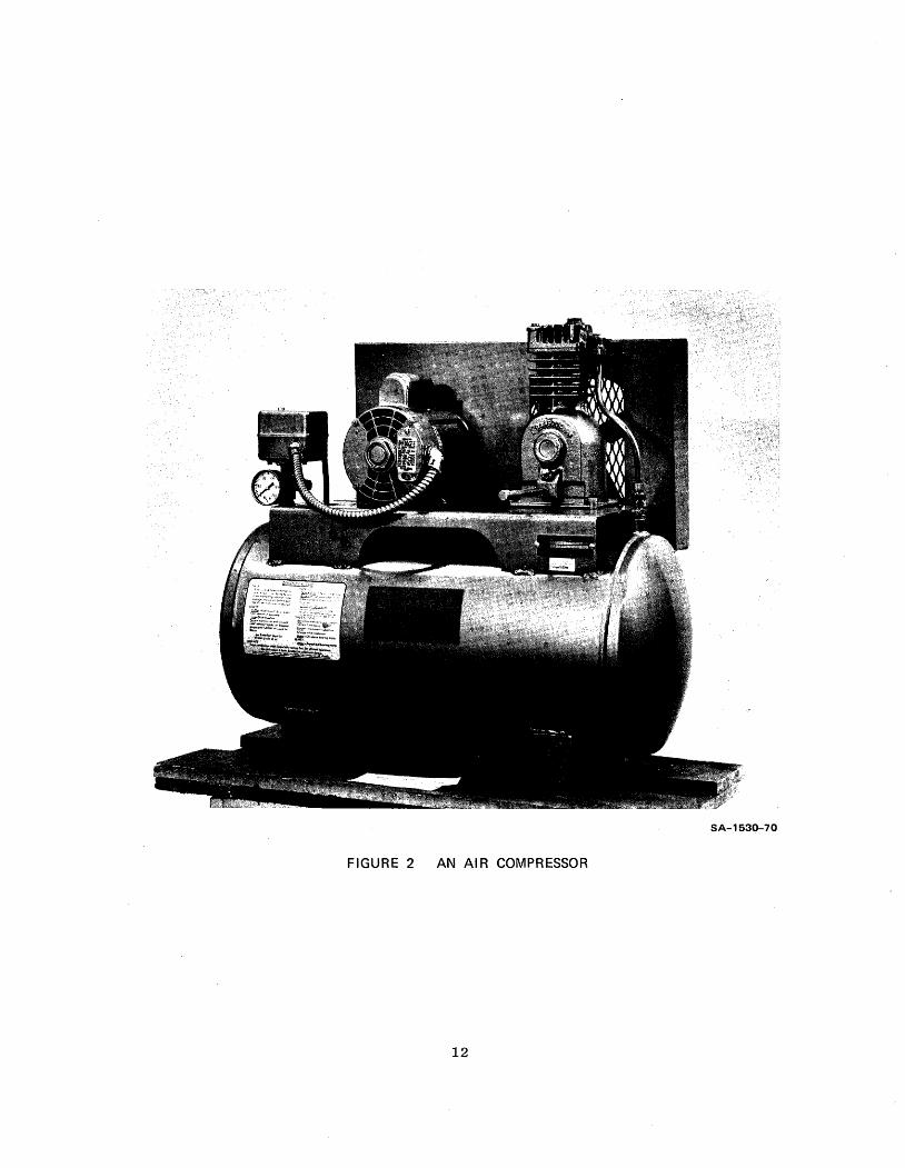
Work on the project has begun by considering a specific device to
maintained in the workstation--namely, a small air compressor (shown in
Figure 2 and described in detail in Appendix A).
A typical main task for the apprentice in the workstation is to
check out the air compressor and prepare it for operation. Thi s task
will involve several subtasks, including
Operation of the compressor and its components
I nspection and test
Diagnosi s of fault Replacement and/or repairs of components
Assembly and disassembly of the compressor and its com-
ponen t s
Service operations such as lubrication and cleaning.
In Appendix B we present in some detail an analysis of the air-
compressor checkout task. This description elaborates some of the sub-
tasks that will be faced by the apprentice and indicates how the demon-
stration system can aid him.
Capabili ties of the Demonstration System
Dialog
Before listing the specific capabilities of the system, we
want to present transcribed excerpts from a tape-recorded dialog between
a human expert and apprentice. This dialog serves as the basis for in-dicating what kinds of knowledge and abili ties the system must have. Italso defines our ultimate goal--to be able to duplicate the performance
of the human expert. We do not expect our five-year demonstration system
to attain that goal, but we do' expect it to be capable of participating
in a dialog much like the one presented here. In the sections following
SA-1530-
FIGURE 2 AN AIR COMPRESSOR
fi ve-year system.
the dialog, we describe explicitly the anticipated capabili ties of the
We have provided comments with the dialog to elaborate on what
the expert is doing at each stage. These comments are intended to provideinsight into what abilities will be needed by a computer-based consultant.
During the experimental session that produced this dialogue
the expert was shielded visually from the apprentice and the compressor
so that all communication was through speech. This experimental situationserved to elici t interesting verbal descriptions from the expert and alsoto illustrate how the lack of vi sual communication severely restricts the
expert' s abi Ii ty to guide the apprentice and monitor the performance ofthe task.
We present a rather long section of the dialog to illustrate
the many capabili ties that must be possessed by such a system. The reader
may want to scan over this section quickly on a first reading.
The dialog begins wi th the compressor disassembled:
Dialog
Expert: The task is to re-assemble the compressor.
Apprentice: Uh huh.
E: The first thing we ll do
if to attach the motor to
the platform.
Attach the motor to the
platform? O. And now
let' s see. Thi s lookslike. . . , this must be amotor , and um.... Let'see, that' s number 17
there, and number 17 ismotor or gas engine. O. K.
Comment s
The expert provides an over-
view.
The expert determines a se-quence of operations (i. e.,a plan) that pertains to the
task
The apprentice is looking at
a di agram wi th part s numbered.(The laser pointer would have
helped here; the expert could
merely have pointed at the
motor and platform. Al ter-natively, vision would have
made it possible for the ap-
prentice to point and ask for
verification. )
DialogYes, and it should beplaced on the platform
and it is connected to
the platform by four
bo 1 t s .
A: Now, where on the plat-form should it go?
Near thecan tell
from its
by where
left side. Youthe position
previous positionthere s no p int.
A: Ah hah:
The sha ft 0 f the motorshould point toward the
wall and should extend
through the belt housing
frame.
A : R i gh t . 0 . K. Now it' s...I have it positioned cor-
rectly.E: O. K. Now find a set of
four bolts. Each bolthas a nut and three
washers attached to it.
A: O. K.
Be careful about the
order of washers. Thereshould be one washer be-
tween the bo thead and the
motor.
E: Yes.
CommentsExpert realizes that appren-
tice has identified and found
the motor.
The expert answers a question
that provides more detai 1 about
the operation. Location specifi-cation is such that a human can
easi ly understand it. (Laserpointer would have helped.
The expert provides sti 11 moredetai 1 in response to the ap-
prentice s question. He makesthe position unique. (Visionwould have allowed the expert
to verify correctness.
The expert realizes that the
motor location difficulty is
resolved. Expert gives adi stingui shing-features
description of the bolts so
that the apprentice can
identify them among the
other parts on the workbench.
The expert is aware of common
errors that humans make and
therefore, gives a warning.
The expert must be able to
understand and respond to the
apprentice s descriptions ofwhere the washers should go.
DialogOne is underneath the
uh. . . the uh... Ii ttle plat-form that the motor sits
on but on top of the....They re all three in
di fferent places.
, that' s not correct.
A: They re all together?
E: The first one is betweenthe head of the bolt and
the motor.
A: Yes.
E : And the other two are
below the platform.
A: Oh, the other two arecompletely below the
platform.
E: Yes, the smallest onewhi ch is a lock washeris next to the nut.
A: I see.
The purpose for those
washers is that the motor
has to be able to slide
back and forth to adjust
the tightness of the belt.The two large washers areto faci Ii tate that , andthe small washer is a lock
washer which keeps the nut
from coming loose.
E: Are you working on thesecond bolt?
A: Yes , I ' m on the secondbo 1 t now.
E: O. K
Comments
Meaning they all go together.The expert begins a more detai leddescription of the bolt assembly
to alleviate the difficulty.
The expert gives a functional
description of the washers to
increase the apprentice s under-
standing of the assembly. Suchan understanding should allowthe apprentice to further verify
that the assembly has been made
correctly.
The expert must maintain a model
of the current si tuation so thathe can respond to di fficul tiesand to questions. (Vision wouldhelp here, although this would
be a hard vision problem.
(Vi sion could be used here tocheck
. )
DialogA: O.K. All four bolts are
now in place and loosely
fastened.
E: O. K. Would that task havebeen significantly easier
if the belt housing frame
had been removed?
A: Which is the belt housingframe?
E: I t is the vertical pieceof sheet metal at the
rear of the platform.
Well, not significantly,no . I don t thi nk i
would have made too much
difference. I t wouldhave been easier if the
platform that the motor
si t s on were removed fromthe cylinder at the bottom.
Yes, but the platform andthe cylinder are welded
together and, therefore
cannot be disconnected.
Can you give me any ad-
vi ce that I could gi in the future to a person
doing that task?
Oh yes , I found on thefinal bolt that it is
easier to keep both hands
underneath the platform
and let the weight of the
bolt push it through the
washers. So, it wasbetter to leave both hands
underneath the platform
so tha t I had two hands to
manipulate the washers and
bol t with.
Comments
Since this was a difficult step,the expert asks for feedback
from the apprentice. In this
case, the expert makes ahypothesis for the apprentice
to comment on.
This is a descriptive and
posi tional definition. Thesystem must be able to describe
ts for identification. (Laserpointer would have helped.
The cylinder at the bottom
is a description of the tank.
The exp rt understands the ap-
prentice s comment , recognizes
the impossi bi Ii ty, and asksfor any advice.
To understand this suggestion
the expert would have to know
that the phrase "on the finalbolt" tells when the apprenticefound an easier way of doing
thi s task. I t does not indicatethat the suggestion is relevant
only to the final bolt.
DialogO. K. Thank you. Isany special ordering
the bolts that would
significantly better
any other?
there
than
A: No, I don t think it would
ha ve made any di f f erence
E: O. K. Thank you. Next wewant to attach the wires
to the motor. There isa cable coming out of the
pressure swi tch.
A: Yes.
E : And i t ha s two orange-colored wires at the end.
A: Yes.
E: Those are to be insertedthrough the ho Ie in the
side of the rear of the
motor.
A: Uh huh.... I see it.E: Each wire is to be attached
to a bolt.
A : Bolt? Yes. Does it matterin which order we uh...which one goes to which?
E: No, it doesn
A: Ah: Good. Now, should unscrew the nut s from thebol ts?
E: No , the wire goes on topof the nut.
CommentsThe expert realizes he has
gi ven the apprentice an un-ordered set of operations;he asks if order is important.
" refers to "a special
ordering of the bolts.Each assembly operation begins
wi th the expert helping the
apprentice to locate the parts
to be connected. This is fol-lowed by a series of steps to
achieve that connection.
The expert uses color as the
distinguishing feature. (Thelaser pointer would have helped.
The expert uses the relative
terms " side" and "rear.
The expert should be able toanswer questions where the
apprentice suggests an operation
to be done and the expert ap-
proves or di sapproves.
DialogA : I see.
E: There is a pair of othernuts.
A: Other nuts:
There is a pair of nuts
that are si tting on thedesk They are close to
a small plate about three
inches long.
Wai t a minute--should I be
looking for the nuts, or
should I.... I havenput the thing in place
yet.
E: O. K. Put the wires inplace so that the loops
are over the bolts.
A: O. K. They re both in
place.
E: O. K. Now we want to findthe two small nuts.
A: O. K. I' ve found two nutsbut they seem to have
screws next to them.
E: Yes, that' s O. K. Thosescrews go into something
else.
A: Those are different screws.
E: Yes.
A: All right, I' ve found twonu t s .
CommentsThe expert erroneously assumes
here that the apprentice has
put the wires in place over
the bolts. (Vision would havehelped avoid this error.
The expert must help the appren-
tice find all the parts needed
to complete the assembly opera-
tion. Location information isgiven by the expert, indicating
what is close that may be easier
to find. (The laser ,pointerwould have helped.
The expert corrects his model
of the current situation.
The expert recognizes that since
screws and nuts are together
the apprentice assumes them
to be a set. The expert makes
a comment to correct that assump-
tion. (Vision would havehelped. )
Di alogE: I suggest you start them
by hand.
A: All right. One of them
, . . .
and now number two
i s on.
E: Now, you need to tightenthem using a nut driver.
A: A nut driver! What' s a
nut dri ver?
A nut dri ver looks like ascrewdri ver and is in the
yellow plastic case leaning
against the wall.
A: The yellow plastic case..., I see the yellow
plastic case. Yes.
E: The driver is 11/32 inch.
A: Yes, it says 11/32 righthere on the handle
Number 11.
E: O. K. , you can use that tool
to tighten the nuts.
A: O. K.
E: Now, the loop at the end ofeach wire should be over
the bo 1 t .
CommentsThe expert could have assumed
that the apprentice could
attach the wires without
further assistance, but by
now he has a rough model of
the apprentice s level of
expertise and decides that
detai led instruction is needed.
(Vi sion could be used toverify this.
The expert knows what tools
should be used for each opera-
tion and can help the appren-
tice identify and locate tools.Descriptions are by analogy,color, and posi tion. (Laserpointer would have helped.
The expert knows that handle
color uniquely identifies which
nut driver.The expert uses very detai ledspecification to verify acqui-
si tion of the correct tool.
Since this operation has in-
vol' ved several sUbsteps, theexpert initiates a checkout
sequence before proceeding.(Vision might have helped
here. )
DialogA: Uh-huh.
And it should be between
the nut that you are
tightening and the nut
that was already on the
bo 1 t .
A: I understand. Should itbe very tightly tightened?
Or just , uh, snugly?E: No, just snug.
A: All right. We re done.
E: O. K.
A: Should I put the nut dri verback?
Yes, please. Now we wantto attach the plate to the'
back of the motor. Theplate covers the wire con-
nection that you just made.
A: Uh-huh.
E: The plate is approximately3 inches long and one inch
wi de .
A: Oh yes I see it.E : O. K. and you use...
A: I t says lubrication on i do not overoi 1 ?
E: Yes, that is it.
A: Ah-hah
Comments
Tight " and " snug" are fuzzyterms. Note that vision couldnot help here.
The expert needs to keep track
of the location of each tool
in the workshop. Expert re-lates next operation to the
previ ou s one.
Again, the expert helps theapprentice find the parts in-
volved in the assembly' step.(Laser pointer would have
helped. )
Expert is interrupted by a
question from the apprentice
recognizes it as a verifica-
tion of the plate identifica-
, and responds accordingly.
(Vision could have enabled
verification without such a
lengthy dialog ; the apprenticecould have held the piece up
for the expert to see.
Di alogAnd you should use the two
screws that you mentioned
earlier.A: I see.
E: Now, slide the pulley ontothe shaft and tighten the
screw down.
A: I should hand-tighten it.E: No, use an Allen wrench.
A: An Allen wrench? What'an Allen wrench?
We have a combination
Allen wrench. First
all, an Allen wrench is ahexagon-shaped rod that
wi 11 fi t on the head oftha t screw, and the
particular tool that we
have looks like a pocket
knife, since it has...
A: Oh. I see... just likea pocket knife... now. . . .
E: O. K. Is it true that thepulley is on the shaft?
Yes the pulley on theshaft.Yes and the screwtightened?
The screw tightened.
The screw next theflat part the shaft?
yes the screw is on
the flat part the shaft.
O. K. Now need to work
on the pump.
Comment s
Expert refers to a past eventto help the person locatethe screws.
The expert uses an an analogy
to describe the tool and recog-
nizes the interruption from
the person finding it. (Laserpointer would have helped locate
the set of wrenches.
Again, the expert asks questionsto update its model and to
cause the apprentice to go
through a checkout procedure.(Vision could have verified
thi s. )
DialogThere s a problem coming
up. There s a.. . on the...uh. . . thi s part that'sticking up in back that
has a protrusion. Ohperhaps my shaft is....
, perhaps there
another shaft. There
a fat shaft and a thin
shaft. Oh yes, those seemto fi t better wi th the...uh. . .. Well, let' s seeshould the fat shaft
point toward the wall or
should the thin shaft
point toward the wall?
I ' m not sure I understandthe description. The shaftthat should point toward
the wall is the longest
protrusion from the pump,and it has a small half-
moon shaped piece of metal
si tting near the slot.
A: So, the longest protrusionshould go toward the wall.
E: Yes, that' s correct.
Specific Capabili ties
Comments
The expert need not understand
everything the apprentice says.In thi s case, the expert under-stands the nature of the problem
and can therefore respond appro-
priately.The apprentice and the expert are
using different descriptors for
the shaft; e.g.
, "
fat " and " thinversus " long protrusiop." andhas a small half-moon shaped....
In this case, the apprentice
alters his descriptors. (Withvision the expert would have
understood fat and thin and
this problem would have been
avoided. )
In analyzing the preceding dialog, we can group the capabilities
of the expert under the following headings: planning and execution moni-toring, vision, and natural language. In the remainder of this sectionwe shall list the specific capabili ties of the five-year demonstration
system as regards these topics. Then, in the next section, we shall dis-
cuss the research problems connected wi th them.
Planning and Execution Moni toring
for planning and execution moni toring:
The expert system will have the following capabi Ii ties
( 1) The basic capabili ty to generate step-by-stepplans (i. sets of instructions) for con-
verting a device (e. , the compressor)
from one arbitrary state of assembly
into another state. Thi s capabi Ii will exist at several levels from
major components (e. , removing the
pump from the compressor) to the simple
fasteners (e. , removing the connecting
pin from the pump pi ston) .
(2) The capabi Ii ty to generate plans in a
hi erarchical fashion in order to gi vethem to the apprentice at a level of
detail that matches his expertise.The system wi 11, upon request by theapprentice, provide more detai ledinstructions for any step in the
reconfiguration process.
(3) The ability to answer specific
questions about instructions it
has given, questions like
, "
Whatis the purpose of thi s step?" orWhat kind of wrench should be
used for this step?
(4) The capabi Ii ty to gi ve technique-related advice when the apprentice
is having difficulty with a step.Such advice might be
, "
Tighten thenut with your fingers before using
the wrench" or "Pulley alignmentcan be tested by placing your hand
across the front of both pulleys.
(5) The capability to give the apprentice
step-by-step instructions for diagnosinga malfunctioning device (i. e. , trouble-shooting). The system will be sufficientlyknowledgeable about the nominal behavior
of the device to be able to recognize
and analyze abnormal behavior.
will possess general knowledge about
the kinds of malfunctions. The apprenticewi 11 be asked to perform tests on thedevice to assi st in the generationand verification of the malfunction
analysis.
(6) The capabi Ii ty, once the trouble-shooting is successfully completed
to guide the apprentice through a
repair procedure. Often, the repairprocedure wi 11 be simply to replacea component , in .which case it wi be equi valent to a disassembly-
assembly reconfiguration procedure.
(7) The capabi Ii ty to describe the use
of the tools found at the workstation.Hence, the system will be able to tellthe apprentice which tool to use for
a step, help to identify and locate
the tool, and give instructions onits operation.
(8) The capabili ty to give warnings and
reminders to help the apprentice
avoid common errors and to alert him
to irreversible or dangerous steps.Similarly, the system will be able to
inform the apprentice about such
things as the cri ticali ty of a step,the accuracy to which an adjustment
must be made, and the tightness re-
quired for a fastening.
(9) The capability to monitor and tnspect
the apprentice s work to ensure that
the operation is proceeding nominally.When the system becomes aware of an
error or of an unexpected event (from
(10)
interactions with the apprentice
or from the system s sensing devices),
it will alter instructions to the
apprentice to deal effectively wi the new situation.The capability to take advice from
the apprentice (or other humans).Thi s task, in keeping with our basicpremise that the system be a reposi toryof expertise, appears to be a difficult
one, but we can envi sion the acceptanceof advice in at least two modes. Firstthe apprentice could answer specific
questions from the system. (For exampleCan you suggest a preferred order for
removing the motor-mounting bolts? " orould it have been easier to install
the motor-mounting bolts if the belt
housing had been removed? ) Secondthe system could elici t advice from
the apprentice and simply store it in
the form received. Thi s advice couldthen be repeated to another apprentice
having difficulty with the step, orit could be exami ed at a later timeby the system designers for possible
incorporation into the system s knowledge
structure.
Vision
The vi sion subsystem wi 11 be capable of rendering a range
of services of at least the scope and difficulty of the ones listed
along wi th samples of specific questions , below:
( 1) Part description
(2) Part identification
Wha t co lor is thepump? "hat are the dimensions
of the washer?
Wha t part or part s arelying on the table?
1 s thi s a box wrench?hat is the laser
pointing at?
(4) Performance
I s the hole too large?s the cord frayed?
1 s this the correct part?
Is the belt tight enough?
Has the assembly been
accompli shed correct ly?
moni toring "Tell me when thewrench hand Ie reache sa horizontal posi tion. "What is the reading on
the pressure gauge?
Has the last bolt been
installed yet?
(3) Visual inspection
(5) Part and tool location Where is the hammer?
(6) Graphic input/output Point the laser at
the upper left corner
of the belt housing
frame. "i splay an exploded
view drawing of the
motor. "Adjust the TV camera
to obtain a closeup
view of the flywheel
and fan belt.Outline the pressure
swi tch on the di splay. "
(7) Assistance in planning "I s there a spaceon the table in which
we can set down the pump?
I f not , what must bemoved?Wi 11 the grommet fit
into the hole?
I s there enough spaceto remove bolt X without
removing the flywheel?
Natural "Language
r goal is a system that understands connected speech at
least as well as will the ARPA 1976 Systems. More specifically, we
expect to handle task-related utterances in that subset of ordinary Eng-
Ii sh expected to occur in the workstation environment in a few times real
time. The utterances will contain words selected from a 1000-wordvocabulary, and they wi 11 consist of syntactic constructions for the
relevant subset of Engli she The number of levels of embedding and thekinds of conjunction and ellipses allowed will be limi ted. These limitswi 11 not be chosen arbi trari ly. We wi 11 study protocols to determinehow effort should be spent to extend our capability to accommodate nat'ural
English and where limits are likely to be easy to impose.
We do not expect to be able to handle false starts, but
we do hope to handle short intra-sentence pauses. The system will not
be able to learn new words. Input will be from a good-quality microphonein the workstation environment. How close we come to this goal depends
of course, o the progress achieved by the ARPA speech-understanding
projects, especially in work on the acoustic and phonological parts of
their systems.
The speech output will be relatively unsophisticated
lingui stically, although we do expect the system wi 11 be able to generate
proper kinds of simple reference. Our efforts in this area will be con-
centrated on procedures and representations necessary for generating
descriptions of objects and locations that are easily understood by people.
I I I RESEARCH PROBLEMS
The capabili ties that we have just discussed are still beyond the
state of the art in computer science, but it seems to us that they can be
achieved in five years by a well focused and well planned research project.Here we shall discuss some of the research problems confronting the design
of the demonstration system. They fall under the same three headings ofthe last section- namely, planning and execution monitoring, vision, and
natural language. To these we wi 11 add a fourth, dealing with the special
problems of integrating these abilities into a smoothly running system.
Planning and Execution Moni toring
The major problems here concern the automatic generation and execu-
tion of procedures for troubleshooting or reconfiguring the equipment.
These procedures, or plans, must be constructed at varying levels of de-
tai 1 to match the apprentice s capabi Ii ties, and the system must "under-11 stand the steps of the plan so that it can answer questions, monitorprogress, and provide new plan steps when unexpected situat ions develop.
A good deal of previous work has been done on this subject , and it
can be used as a b se. We might mention specifically the following
relevant work in automatic planning:
The STRIPS planning system and its extensions. 3-6
The QA4 robot planning programs. 6-8
The SHRDLU system for planning in the BLOCKS world.
The HACKER system for generating and debugging plans
in the BLOCKS world.
Many of the problems not yet adequately handled in previous work are
discussed by Fikes, Hart, and Nilsson.ll Especially important is theneed to develop a hierarchically-based planning system that can operate
at varying levels of detail. Nilssonl2 and Sacerdoti have designed
simple hierarchical systems, and these designs wi 11 be used as prototypes
for the development of a system that can plan effectively in the complex
environment of the workstation.
Our system will need to develop plans that are more complex than
simple sequences of steps. For example, we will need various kinds of
loops and conditionals ("fasten bolt 1, bolt 2 , bolt 3, and bolt 4
loosely, " or " loosen the set screw until the pulley moves freely on theshaft ); sets of unordered steps ("tighten the four bolts ); and sets of
steps with a preferred, but not required, ordering ("remove the ten screws;
you may find it easier to remove the bottom row before the top row
An important research task is to develop a representation for plans that
will allow us to generate, execute, and monitor such complex operations.
The workstation environment wi 11 require our system to be designed
so that generation and execution of plans will be interwoven- in a much
more dynamic fashion than has been the case with previous planning systems.
For example, questions from the apprentice about a particular step during
plan execution may require the system to generate a new detailed plan
that elaborates the step in question. Unexpected events or apprenticemi stakes during plan execution may require the generation of new plan,
steps to get the operation back "on the track. 1f Also, plans may include
inf rmation-gathering steps whose results affect the course of the opera-
tion to the extent that planning cannot proceed beyond them.
The system will also be able to answer questions about a plan at any
level of detail. To do this we will need (again) efficient ways of
representi ng plans that reveal the purposes, precondi tions, and results
of each of the steps in the plan.
Fundamental to all of the capabili ties we have discussed so far isthe need for a rich hierarchical model of the workstation domain including
the equipment being worked on and the apprentice himself. A major
research task is the development of representations for this model that
wi 11 allow the system to store and effectively use the information thatan expert consultant is expected to have.
Some of the procedural information in these models will essentially
be "canned" plans for doing common detailed operations such as tightening
a nut-and-bol t assembly. During plan generation these stored procedureswill be instantiated and used as detailed expansions of higher levelplanning steps. I nefficiencies and inadequacies may appear in detai ledplans produced by the concatenation of such stored procedures, and the
plan generator must be able to optimize and debug these plans appropriately.Some new work by Sacerdoti on developing special programs to cri ticizeplans may be useful for this problem, as may Sussman s work on HACKER . 1 0
Vi sion
The vi sion subsystem may be viewed as a set of information-gatheringroutines that may be called by any part of the consultant system to ob-
tain speci fic kinds of information about the workshop environment. Thi subsystem is a specialized consultant system in itself, including capa-
bi Ii ties for question answering and problem solving. What makes itnecessary to consider the vision subsystem as somewhat distinct from the
general problem-solving effort are the specialized requirements for visual
data acqui si tion and image processing, and the representation of semanticconcept s such as shape, color, and vi sual appearance. However, many of
the techniques we propose for perceptual strategies are applicable to the
rest of the system.
The vision-related research issues we will attempt to solve are in
two broad areas: utilization of three-dimensional visual data and genera-
tion of perceptual strategies by interactive or automatic means.
Our first research objective ill be to investigate the resolution
and accuracy obtained by our laser range finder. The feasibility of ob-
taining range by phase measurement on a modulated laser beam has already
been demonstrated. However, the limiting accuracy of the system is un-
known, as are the tradeoffs between modulation frequency (wavelength),
lineari ty, resolution, noise, and limiting range. These questions shouldbe resolved through continued hardware development of our system.
A critical research objective is the development of adequate repre-
sentations of curved three-dimensional objects that are distinguished
primarily by structural shape descriptions. , We do not necessarily en-
vi sage a single comprehensive formali sm for describing shape but wi
continue throughout the course of this project to develop representations
for more and more complex structures. Among the desired characteri stics
of a set of representations are the following: They should be capable of
representing an arbitrary degree of detai 1 without making the retrieval of
the coarser features unwieldy; they should be capable of relating to models
of surface characteri stics including reflecti vi ty; color, and texture;
they should be capable of characterizing relationships among parts in an
assembly; and above all, they should enable the system to produce (under-
stand) descriptions easily understood (produced) by humans.
The algori thms by which the appropriate representations are abstracted
from visual and range data are an integral part of the research on repre-
sentation. The set of available representations and the algori thrs for
obtaining and transforming these representations we refer to as our " li-brary of vi sual primi ti ves. "
For the first few years, we will concentrate on representing a fixed
set of specific parts. These representations will be "model-based" in
the sense that they refer to the precise geometric details of specific
prototype parts. As the research proceeds further, we hope to become
more and more " semantic-based, II so that the features by which we recognize
say, a flywheel, do not include the number of spokes, but rather charac-
teristics associated wi th most flywheels (I t is round and its mass is
concentrated toward the rim). An eventual goal is to use general knowledge
about , for instance, compressors in order to analyze a compressor the
system has never encountered before and to correctly identify its parts
based on their functions.
To date, most scene analysis programs have been wri tten to accomplisha limi ted objective using a small number of specialized data extraction
techniques applied according to a fixed set of rules. No such program is
sufficiently general to accomplish the variety of objectives listed above.
Rather , a general vision capabili ty must be based on a strategy programthat can select from a large repertoire of specialized techniques those
best suited for answering a particular question.
The techniques available for answering a specific request may range
from a simple table lookup to a major analysis of an entire scene. Inaddi tion, the system can request the apprentice to aid in visual acquisi-
tion and interpretation. The visual subsystem will have a planning capa-
bili ty that will make use of knowledge about the context of the requestand about the capabilities and limitations of the techniques available
in order to arri ve at an efficient way of answering the request. Othersubsystems can advise the vision subsystem on how best to obtain the in-
formation they require.
Until our library of visual primi ti ves is sufficiently rich to
describe compressor parts, we will continue current work on perceptual
strategies in the domain of room scenes. Research topics wi 11 include
the interactive specification of recognition strategies, the automatic
generation of recognition strategies from features which an operator con-
siders to be important , the representation of knowledge about a system I s
own capabilities, and special techniques for rapid identification of ob-
j ects in a known context.
I n the early stages of the program, recognition strategies for com-pressor parts will be hand-coded into the system and based on "distin-guishing features " a set of tests that may economically distinguish
among parts in a limi ted context. Later, we hope to be able to inter-acti vely " teach" the system which features or characteristics of an ob-
ject may be reliably used for identification.
Finally, we are studying the feasibili ty of using a constraintsatisfaction approach to narrow the . range of possible interpretations forparts of a scene. Many constraints govern relationships of parts to each
other in an assembly. These constraints arise from consideration of the
function or operation of the parts and ' from methods of fabrication or
assembly. For example, a motor must have a power cable connected to it;the absence of any such part connected to a particular component makes
it unlikely that the component is a motor. It is 'hoped at a sufficient
number of constraints will be discovered so that elimination of impossible
relationships leaves only a small number of consistent interpretations
for a scene.
Natural Language
Our system will be one of two participants in goal-directed dialog.
To be understood, a sentence occurring in such a dialog must be inter-
preted in the context in which it appears. Both the discourse context
(the actual dialog occurring so far) and the situational context (the
current workstation environment) are important. Thus, the language system
will have to incorporate information from the workstation, an understanding
of the workstation tasks, and a memory of recent events. It will have tobe able to obtain information via vision and planning. Hence, the major
emphasis in natural language will be in three areas: discourse semantics
pragmatics and model interaction, and description generation and compre-
hension. We will be attempting to answer such questions as
What information is available from the task model and
the state of the dialog to guide understanding?
How should this information be structured?
How can it be incorporated into a system that understandsnatural language?
How can descriptions generated by people in task-oriented
si tuations be characterized?
What representations and algori thms are needed to generateand understand these kinds of descriptions?
What models and algorithms can be shared with other parts
of the system (vision, planning)? How?
Di scourse Semantics
Our preliminary studies of task related dialogs have revealed some
general paradigms for these dialogs. For example, an assembly dialog
consists of many subparts of the form
GET NEXT PART PUT IN PLACE FASTEN.
Each of these subparts may be many sentences long, and each may include
subparts. For example FASTEN might include
DETERMINE HOW FASTENED GET TOOLS LEXTRA PARTS (maybe) J TIGHTEN.
The most interesting property of this hierarchical structure is that
references operate mostly wi thin a subpart. A reference that goes out-side the current subpart must be highly specified; e. , it must indicate
what other subpart the object being referred to was mentioned in. So
for example, inside of GET TOOL there may be such elements as references
(e. g.
, "
i t
" "
them ) to different kinds of tools and descriptions of
di fferences among tools. However, once the tool has been located
references operate among elements of FASTEN (e. g. , what is being fastened).
In effect , the discourse pops up a level. Consider the following dialogbetween the expert and the apprentice:
You need an Allen wrench to tighten the screws.
What size?
l/16 inch.
I can t find one. Where are the wrenches?They re in the top left corner of the toolbox.
K. Got it. How tight do they have to be?(The last " they" refers to the screws, not the wrenches.
To understand thi s kind of dialog, a structured hi story of thediscourse must be kept. A major thrust of our research will be to charac-
terize thi s structure and to determine a representation for it and algo-ri thms for using it to aid understanding.
Pragmatics and Model Interaction
The semantic component of the speech system wi II need a detai led
model of the devices being worked on in the workstation to understand
both what is being said and what the state of the task is. For exampleit will need to know what supports (or is supported by) a part , how
parts are fastened to each other, and what spatial relations exist between
parts. This kind of information is needed to understand statements like
The washer on top of the spring is worn " or "I removed the belt housingcover.
We wi 11 have to define general operators for working on these
models. As well as aiding understanding, these operators will form an
important communications link between the language and planning components
of the system.
I put the nut on the bolt " and "I put the nut on the table
mean very different things. These different senses of "put " will be ex-
pressed by different operators (e.
, "
screw-on" and "place-on It is
these operators that will be communicated to the planning component.
Much of thi s task-related information wi 11 be needed by thevision and planning components of the system. To construct the discourse
history, the system will have to know what subsequent states and what
problems can follow from a gi ven state. Computing these consequences of
a state is really what is meant by planning. Thus , a second major area
of research will be determining what task-related information the language
part of the system needs and how this will interact wi th the operators
and models in the planning and vi sion components.
Description Generation and Comprehension
Descriptions of parts , tools, and locations are an integral
part of expert-apprentice dialogs. In order to communicate effectively
with people, the system will have to be able to understand (generate)
descriptions that are easily produced (understood) by people. Information
from both the preceding dialog and the workstation environments will
play an important role.
We first consider the linguistic problems that arise in the
construction and comprehension of descriptions. The system will have to
be able to use and understand reference and substitution. For example:
Find a set of four bolts. Each one has a nutand three washers at tached to it.
K. I' ve found four bolts.
Put the bolts in and leave them-loose.
What should I do with the nut after I put the
bolts in place?
Once the system has used " four bolts " it must refer to them as
the (four) bolts" or " them. If it uses "four bolts" (indefinite), the
user wi II be confused; he wi II probably think the system means another
four bolts.
The system will also have to handle ellipses. Consider the
following dialog:
Have you loosened all the bolts?
, just the front ones.
The last sentence is a fragment. It is equivalent to the statement "
have loosened only the front bolts " although neither " loosening" nor
bolts " appear in it.
Planning problems are also involved in generating good descrip-
tions. Ease of user understanding means the detail of a response will
depend on its context (the level of the current task, whether the response
is a followup to a previous response or a new topic, the amount of detail
the user has required previously, and the kinds of features which di stin-
guish the object being described from others in the current context).
The question
, "
Where on the platform does the pump go?" might be answered
Near the left side; you can tell its posi tion by where there is no
paint. Thi s has obvious advantage over answering, " 25 inches from the
left side and 4. 76 inches from the front edge " or worse yet
, "
At posi tion
, 4. 76. Similarly, "Which wrench?" can be answered
, "
The big one
if there are only two, or "The one with the red handle " if there are
many with different colored handles. It is necessary to answer
, "
The
liB-inch one " only if there are many and they all look alike.
The system wi 11 have to be aware of the user s orientation.
Front , back, and side are all relative descriptors. If it is not surethe system will have to orient the user , e. g. , by telling him to face
the compressor wi th the highest part of the compressor away from him.
Once it is aware of the user s orientation, the system can give descrip-
tions from the user s point of view.
Ideally, seeing from the user s point of view would be considered
in its less Ii teral sense. The system would gi ve descriptions in terms
of characteri stics the user has already indicated he is aware of. Thi s
does not preclude teaching the user new names, tools , or techniques; it
only says they wi ll be explained in terms he can understand easily.
I t is important to note that people do not usually descri be
objects in the fewest bits possible. Instead, they seem to intend to
enable the listener to locate the object as rapidly as possible. Descrip-tions involve a narrowing of focus (context) . Typically, the ini tialpart of a description includes a coarse physical characterization of the
object and an indication of its location. For example, one response to
the question
, "
What' s a nut driver? " was
, "
It looks like a screwdriver
and is in the yellow case by the wall. Similarly, "What' s the belthousing cover?" was answered
, "
The vertical piece of metal at the rear
of the platform. Locations are also described by narrowing the focus.
There is a pair of other nuts.Other nuts?
There is a pair of nuts that are si tting onthe desk. They are close to a small plateabout three inches long.
Functional descriptions also serve to speed up the Ii stener ' s
search. To say that an object is used for some job is to say that it
looks like it should perform that job. When there are several objectsof the same color and material in approximately the same location, shape
may be the only distinguishing feature. I f the object to be found hasa complex shape, the simplest and clearest way of describing it may be
to tell its function. Consider the following excerpt from an assemblydialog:
Now we need to attach the condUit to the motor.The conduit is the covering around the wires
that you were working wi th earlier. There
a small part... ur.
. . .
Oh brother.
Wai t a sec.... The conduit is the cover to
the wires?
Yes.
, I see, there s a part that' s supposed togo over it.Yes.
I see. It looks just the right shape too.Ah-hah:
Thi s kind of description based on narrowing of context and
distinguishing features of objects looks very much like what the vision
part of the system will be doing except that it is geared toward features
that will distinguish an object for a person (instead of for a machine).
There is probably a different set of primi tives, but the planning algo-
ri thms should look a good deal alike. The third major area of researchwill be determining these primi ti ves and the algorithms needed to decide
what the easiest ways of describing an object are. This work will in-volve the vision and planning components of the system both in sharing
algori thms for determining distinguishing features and for determining
what the best descriptions are. For example, pointing can often beused partially or completely, to replace a verbal description. No part,
of the system can make this decision alone.
System Integration
There are major design problems involved with putting together an
overall system of this sort. We have already mentioned the desirability
of the subsystems sharing model information. In fact , the discussionhere has been under separate headings mainly for ease of expression. Inreali ty, the overall system will appear much more homogenized. Natural
language and vision tasks will use planning abilities at almost every
step, so we can expect a thorough interdependence between parts of the
system.
A key feature of the system design will be modulari ty. The domain
of knowledge possessed by the system will consist of far too many items
related in far too many ways, for the system to be constructed in a mono-
lithic fashion. Rather, indi vidual microconsul tants wi II be constructed
to deal with separate microworlds (e. g., troubleshooting an electric
motor; using a wheel puller). The overall system wi II assume the respon-
sibili ty of integrating the efforts of the various microconsul tants bydealing with the interactions between them.
Strict adherence to a modular design wi II also make our system
extendible. I t is our goal to have the system extendible in the followingways:
I t will be possible to add new factual information
about properties of tools, equipment , and such
directly to the system without having to alter any
of the model maintenance, planning, deduction, or
retrieval routines and wi thout having to restructure
the existing model information. I n particular, itwill be possible to teach the system about new equip-
ment (perhaps equipment similar to the compressor).
It will be possible
parts fi t together
knowledge is needed
may consi st of more
about already known
to add new information about how
how to troubleshoot , whatever other
in planning. This new knowledgedetailed or augmented information
equipment or new information about
addi tional equipment. Often, this kind of knowledgewi II be in the form of new programs to be added to the
complex of old ones, but it will not be necessary to
reprogram the systems that use this knowledge.
There will be some capability for the system to extractnew knowledge automatically through dialog with the
apprentice or a human teacher and through vision.
We expect additional research problems concerning system integration
to surface during the course of the project. For this reason we shallbe attempting the construction of a complete system early in the project
to provide an opportunity to attack these problems.
I V PROJECT PLAN
Phasing
In this section we shall present our plan for achieving the objec-
tives of our project. There is rto doubt that the specifications for the
demonstration system are challenging. I t seems to us that such a system
could not be achieved in less than five years, and even then, success
will depend on good organization and hard work. Still, we do not thinkit productive to set our sights lower and plan for a shorter period, and
we recommend a five-year project beginning April 1973.
I t also seems reasonable to us to divide the project into two con-secuti ve phases. Our reasons for favoring such a di vi sion are that
(1) It gives Us a clear mid-project opportuni ty to reviewthe course we have taken and make major modifications
to the plan and our method of approach if warranted.
(2) It allows us, during the first phase, to concentrateour work on an appropriately scaled-down demonstration
to test the feasibility of our approaches.
(3) It gives a convenient point for ARPA to evaluate ourprogress.
(4) I t provides a reasonable point at which we can intro-
duce any needed additional computational facili tiesand reprogr ammi ng .
Therefore, we recommend two phases. Phase I , the first three years
will conclude in April 1976 with the demonstration of a scaled-down system.
Phase II , the last two years, will be devoted to completing the work
needed to demonstrate the final system.
The Phase I System
The Phase I demonstration system wi II be a scaled-down version of
the Phase I I system. We expect that bui lding it , a much less ambitious
system, will teach us which approaches are feasible and which are not.
The task domain for the Phase I system will be the same as that for
the final one except that the equipment to be checked out and repaired
will consist of a single, simple air compressor, and the system will be
designed to work with a single user. The workstation will be largelythe same as the Phase II workstation but with fewer tools. Also, we will
not be attempting, during Phase I , to achieve real-time operation. That
, in some cases, there may be delays on the order of 2 to lO minutes
between user queries and system responses.
The Phase I system wi II be demonstrated by Apri 1 1976. We wi II give
more details about it as we describe the specific research milestones
later in this section.
Organization
We can roughly divide the work of the project into four major ac-
ti vi ties: management , system bui lding, system support , and research sup-
port. By management, we mean the obvious acti vi ties of moni toring the
project plan and continuing its development plus day-to-day running of
the project. The system-building activi ty wi II involve integrating the
results of our research into smoothly running demonstration systems. By
system support , we mean the tasks connected with using, maintaining, and
improving our systems hardware and software. By research support acti vi ty,
we mean generating the scientific and technological basis for the demon-
stration systems.
Our resources wi II be split roughly as follows:
Management (Leader: Nils Nilsson) lO%
Systems Support (Leader: Daniel Lynch) 25%
Systems Building and Research Support
(Leader: Richard Fikes) 65%
Systems bui lding effort wi II be small at the beginning of each
phase and grow larger as the demonstration times approach; the opposi
will be true for research support effort.
Research Tasks
The research support activity will initially be divided into the
following major research tasks:
Planning and execution monitoring
Vi sion research
Natural language.
Planning and Execution Moni toring (Leader: Richard Fikes)
Present Acti vi ties
Three major present acti vi ties are now underway. These
are the compressor simulation, the assembly program, and the reconfigura-
tion planner.
Compressor Simulation (Richard Fikes). A simulation
of the actions of the top-level components of a simple air compressor
has been wri tten in QLI SP .13 Thi s simulation makes use of QLI SP assert
teams (simi lar to PLANNER antecedent theorems and to QA4 demons) to model
the dynamics of a compressor. I t is now being extended to more detai led
levels, that is, to simulations of the pump and other components. This
simulation package will be used mainly in planning for troubleshooting
activities. In developing this simulation, we have created special QLISP
constructs for modeling the dynamic states of the compressor (how much
air is in the tank, speed of motor, and so forth) and the ways in which
these states change.
Assembly Program (Earl Sacerdoti). Earl Sacerdoti haswri tten a small QLISP program to study the problem of how a computer system
should gi ve advice to a human and model hi s progress in the assembly of
components. The program gi ves hierarchically organized instructions to
be executed by the apprentice. I f the apprentice informs the system thathe cannot carry out an instruction (perhaps he doesn t know how), the
system gives more detai led instructions on how to accompli sh it. The
system updates its model dynamically at the appropriate level of detail.This system is the basis for a program called the Procedural Net System
now being developed.
Reconfiguration Planner (Richard Fikes) . A planning
system is being designed that will be able to give an apprentice instruc-
tions on how to reconfigure (e. g. , assemble, disassemble, retrofi t, modify)
an air compressor from any arbitrary state to any other. This programwi II be basic to any task requiring physical operations wi th the com-
pressor. This planning system will probably merge wi th Sacerdoti' s Pro-cedural Net System.
To date, we have worked out some preliminary ideas for
modeling information about how compressor parts are to be connected and
di sconnected and for representing an arbitrary configuration of the com-
pressor.
Plans for the Future
l974. During the coming year, we expect to have a systemrunning that can plan instructions for reconfiguration of the top-level
compressor components (e. , pump, motor, fan belt , tank, pressure switch).These instructions wi II be given at any of several levels of detai 1 de-pending on responses from the user. We also plan to investigate how in-
formation about failures can be used to guide planning.
As a part of this system we will develop various QLISP
associati ve deducti ve retrieval routines for querying the data base.
These wi II be based on the QA4 routines already written. 8 They wi II used by the planning system itself, but they will also be available for
question answering. Thus, by the end of 1974, we will be able to demon-strate a system having the abi li ty to answer questions about compressorparts , connecti vi ties, properties of parts, and so forth.
During 1974, we will be developing a store of information
about tools and their uses largely in the form of routines that are used
to plan actions using tools.
We will continue work on dynamic model updating by making
use of environmental information. During 1974, this information will be
supplied primarily through symbolic (rather than visual) interaction wi
the apprentice. This updating abili ty will be used during late 1974 andlater by plan monitoring routines.
Finally, we wi II develop a representat ion for plans that
will also allow us to model the progress and history of the task at hand.
This will be important for monitoring and replanning activities.
l975. By the end of 1975, we will have a multilevel
reconfiguration planner running (i. e. , one that can reconfigure the parts
of the pump and other components as well as those at the top level). Our
model information on which this planner is based will now contain some
information about the user, for example, information about his level of
expertise. We will also begin to put in and use some specialized infor-
mation about troubleshooting. A beginning planning system for trouble-shooting will be in operation by the end of 1975. This will be improvedduring 1976 and integrated with the reconfiguration planner for the Phase
I demonstration.
Earl Sacerdoti is going to be working on a Ph.D. disserta-tion in this general research area (through the Computer Science Depart-
ment at Stanford University), and his dissertation ought to be finished
during 1975. In addi tion we will continue to encourage the participation
of other Stanford students.
The planning capabilities that have been achieved by these
research tasks by the end of 1975 define the planning capabilities of the
Phase I (April 1976) demonstration system. We think that it is not pro-
ducti ve to generate detailed plans now for the course of problem-solving
research during Phase II. These will be developed as the work in Phase
proceeds.
Vi sion Research (Leader: J. M. Tenenbaum)
Present Acti vi ties
We are now working in three mutually complementary vision
research areas that will begin to merge in 1974. First , we have con-structed an interactive scene analysis system that is used for synthesizing
a knowledge base for analyzing scenes.14 Gi ven a particular domain, theresearcher can use the system to experiment with the utility of various
perceptual operators (such as color, texture, brightness, height , orien-tation) for recognizing object in the scene. Through this interactiveprocess) specialized scene analysis programs can be quickly constructed.
(The interactive scene analysi s system has resulted from joint sponsor-ship by ARPA, ONR, and NASA.
A second acti vi ty concerns developing a highly goal-
directed system for answering questions about a scene. Given a questionthis system will automatically organize the appropriate perceptual opera-
tors (based on the semantics of the domain) to locate those objects inthe scene that are relevant to the answer. For example, in response to
a question such as " I s the compressor plugged in? , the system would first
use the distinguishing features of a wall power socket (perhaps the color
of the socket plate) and of the compressor power plug (dull black) to 10-
cate these objects. I f the power socket area does not contain the plug,
the system might answer no; or it might choose to locate the plug itself
knowing the distinguishing features of the power cord, to. provide con-
firmation. At the present time, we are completing the implementation of
this system. I t is based largely on the doctoral research of ThomasGarvey, who expects to obtain a Ph.D. degree from Stanford Uni versi ty
during 1974.
Garvey s system will typically be adequate f6r answering
many questions about scenes; however, it has obvious limitations as a
general perceptual strategy. . In complex environments, it may be impossible
to assign unique interpretations to parts of a scene based only on local
perceptual attributes taken out of context; different objects can have
similar appearance, while objects belonging to the same functional class
can have strikingly different appearances (e. g. , wrenches). Occlusion
and image imperfections contribute to variabilities in appearance. In
these cases, nothing will suffice short of a complete analysis of the
scene.
As a third acti vi ty therefore, we are currently developing
a semantics-based scene-understanding paradigm, in which interpretations
that are ambiguous (based on local perceptual attributes of regions) are
ruled out using contextual constraints in order to arri ve at a consistentand meaningful interpretation of the whole scene. This system is intendedto assimilate a wide variety of independent facts about a pictorial domain
and to produce an interpretation whose quality should improve with the
amount of available knowledge.
In addition to these acti vi ties, we are continuing the
development of a time-of-flight laser range finde 5 that will provide
depth data for picture fields on the order of lOO-by-lOO points.
Plans for the Future
Our future work in vi sion has been arranged into a set oftasks spanning the next five years. These tasks are largely based on ourpresent work and a carefully thought-out vi sion research programtha t now focuses on the computer-based consultant proj ect.
--1974. Effort during 1974 will consist of
Demonstration of a working laser and
associated software to acquire, display,
transform, and calibrate 3-dimensional
image data.
Identification of parts on an assembled
compressor in known posi tion and orienta-tion designated by the system s laser
pointer, a hand held LED , or a displaycursor. (Identification will be accom-plished wi thout explicit use of visionby transforming the part designation to
a known ray in space and computing the
intersection of that ray with a projected
geometric model of the compressor.
l975. Effort during 1975 will include the followingtasks:
Determine the orientation of isolated
compressor parts whose identi ty isknown.
Generate automatically " di stingui shingfeature" strategies for finding objectsin room scenes from declarati ve descrip-tions.Analyze workstation scenes using global
constraint satisfaction methods.
Accomplish visual recogni tion of isolatedparts and tools based on geometric models
and 3-dimensional image data.
Accomplish identification of parts on an
assembled compressor designated by a man
pointin wi th his finger.
1976. Effort during 1976 wi 11 include the followingtasks:
Generate distinguishing feature strategies
for locating a specified part or tool any-
where in the work station.Identify all parts in a subassembly and
be able to determine interconnections.Check part alignment and so forth. (possi-bly uti lizing constraint sati sfact ionmethods) .
1977. Effort during 1977 will include the developmentof man-machine pictorial communication. The system will be able to recog-
nize parts from human verbal descriptions and, conversely, to describe
parts to an apprentice making effecti ve use of the user s contextual
referents. Descriptions will be in list format at first , but , by theend of the year, they will be in natural language at the competence level
of avai lable parsers.
--197B. Effort during 197B wi 11 include development of
an integrated (man-machine) information gathering capability with suffi-
cient problem-solving expertise to provide the range of services needed
by the Phase II (l97B) demonstration system.
The visual abilities of the Phase I (April 1976) demon-
stration system are defined by the vision tasks through 1975. In surmary,
the Phase I system will be able to recognize isolated parts and tools
and it will be able to identify the parts on an assembled compressor as
they are designated by a man pointing wi th his finger.
Natural-Language Investigation (Leader: Barbara Deutsch)
Present Acti vi ties
We are begining to investigate the syntax, semantics, and
vocabulary of the workstation domain. Various protocols have been taperecorded of dialogs between a human expert and human apprentice while
the apprentice was assembling and disassembling the compressor. From
these, we will estimate the requirements for vocabulary, syntax, and
semantics for a continuous speech-understanding system for this domain.
Plans for the Future
1974. So that we can have natural- language input assoon as possible, we will adapt the SRI Speech-Understanding System
Parse~ 8 to accept text input from the workstation domain. For the fi ve-
year system, both the syntax and semantics of the system will have to be
extended. We expect to take advantage of developments in the speech-
understanding project. A major goal in the first year of the project
wi 11 be to determine the syntactic constructions used in goal-directedperson-machine communication. We will begin to extend the grammar in
this direction.
Our focus in 1974 will be on the interface between natural
language input/output and the problem- solving and planning models. We
wi 11 investigate the kinds of information these processes need to shareand how they will interact. For example, all of these processes will
need "models" of the tools and parts in the workstation domain. Naturallanguage processes need these models in order to interpret the input interms of basic operations in the domain. Planning processes need themto decide which tools artd parts to use at which times.
We will also be investigating how dialogue and task-related information can be used to aid understanding in planning, prob-
lem solving, and natural language input/output. We will begin modeling
discourse structure and testing represent at ions and algorithms for in-corporating it in the natural-language understanding system.
Also during this year, we expect to use a commercially
avai lable, isolated-word recognizer as a simple input device. Such a
device can be used for inputting such phrases as "What?
" "
I don t under-
stand
" "
Okay, " and "More detail please.
As regards natural-language output from the system to the
apprentice, we shall postpone developing any sophisticated system until1975. During 1974, the system s responses will be selected from canned
sentences that will be typed out and, toward the end of the year, spoken
on a VOTRAX speech synthesizer.
--l975. During 1975, our text input system should beworking and understanding simple sentences from the apprentice. Modifi-
cations and extensions to the grammar will continue. We will be testing
and modifying our semantic models for the tools and parts in the work-
station domain. We will continue the work on modeling discourse struc-
ture. Emphasis will be on how natural language can share representationsand algori thms wi th other parts of the system.
Work wi 11 also continue wi th the i solated word recognizer
and we shall begin work on automatic synthesis of sentences. Our plans
for beyond 1975 are not worked out in detail, since much of what we will
do depends on the direction of current speech-understanding research.
We do propose to postpone any acoustic level work unti 1 1976. However
we wi II be able to take advantage of the acoustic work done in the speech-
understanding project.
Barbara Deutsch expects to be doing Ph. D. research through
the Uni versi ty of California at Berkeley in this general area.
The Phase I system will have only a limited natural-
language capabili ty, and this wi 11 probably be mainly through the i solated-
word recognizer and a text input system.
Appendix A
DESCRIPTION OF A SIMPLE AIR COMPRESSOR
Appendix A
DESCRIPTION OF A SIMPLE AIR COMPRESSOR
The air compressor we have been working wi th is Sears Model 17209-
1/2 HP Compressor. (It was illustrated in Figure 2.
The essential elements of this unit are
An electric motor (drives the air pump).
A pump (takes air from atmosphere and compresses it into
tank) .
A tank (stores compressed air).A pressure switch (starts and stops the motor at pre-
determined pressures).
A relief valve (releases "back" pressure on pump whenthe motor stops).
A check valve (holds air in the tank when compressorstops and allows the relief valve to function).
We quote from the Sears operating instructions to describe the
maj or features:
PUMPING. In action, when the piston of the pumpgoes down, air rushes in through the inlet valve. Asthe piston starts up the inlet valve closes and the
air in the cylinder is compressed until the pressure
in the cylinder slightly exceeds the pressure in the
piping (aftercooler) connected to the check valve.This excess pressure causes the outlet valve to open
allowing the air in the cylinder to be forced out
through the outlet valve into the piping. As the pis-ton starts down, the outlet valve closes , preventing
air in the aftercooler from rushing back into the cyl-
inder and the cycle starts over again. When the pres-sure in the aftercooler exceeds that in the tank, thecheck valve opens and allows air to pass into the tank.
STOPPING. The compressor continues to pump until thepressure in the tank reaches the point at which theautomatic switch is set to cut off. The pressure inthe tank acts on the diaphragm of the automatic
swi tch (through piping) and when the cut-out point is
reached, this diaphragm distends and , through leversopens switch contacts stopping the motor, and simul-
taneously opening the relief valve. The air trappedbetween the pump and the check valve is thus allowed
to escape through the relief valve. The air in the
tank cannot , of course , escape because the check valve
does not allow the air in the tank to flow back.
STARTING. When the pressure in the tank is decreased
by using the air, arid finally reaches the cut-inpoint" of the switch, the reduced pressure on thediaphragm allow~ the pressure spring to cause the
lever to close the switch contacts and relief valve.This starts the motor and the compressor again be-
gins to pump. There being no pressure in the after-cooler (it having escaped hen the relief valve was
opened) the motor can start under no pumping load
and get up to speed during the time required to raise
pressure in the aftercooler.
From the foregoing 'and from an examination of thediagram, it will be seen that not only must the eLec-
tric motor and air compressor itself be kept in pro-
per working condition, but that the check valve and
relief valve must work properly. If the check valveleaks, then the air stored in the tank will escapethrough the relief valve when the compressor is not
running because the relief valve is open all the
time the switch contacts are open.
Also, if the relief valve doen not close properlywhen the compressor is running, the air (or most ofit) pumped by the compressor will not go into the
tank at all , but will pass out through the leaky
valve. Or, if the relief valve does not open prop-erly then the back pressure can not be relieved and
the motor must start the compressor against pressure
which consumes extra power and may damage the motor.
The maj or parts of the compressor are listed in Figure A-l (taken
from the Sears manual).
The parts list for the pump unit is given in Figure A-2.
Reference Part Reference PartNumber Number NAME OF PART Number Number N'AME OF PART
690 Allercooler Elhow 3 " Flare Tuht x
y,"
Pipe12191 Pressure Switch for (17209) 102. 17210, 102.17220 (17218)
Pump - St'e Fi,gure 9n055 Afu,rcooler for 102. 1700 I , 102.170 II 102. 17011, 102.17021 and
102. 17021 , 102.170 6 and 102. 170 102. 17041H057 Mtercooler for (17199) 102. 17200 , (17209) 102. 17210 13858 Pressure Switch for 102. 17046
and 102. 17220 (17218) 32473 Pressure Switch for (17199) 102. 1720098556 Elhow CooneClor- ' " Tube x Pipe Thread Pressure Switch Relief Valve. When ordering\5681 Ch(' ck Valvt' See Fi/(ure 4 for ParIs Relief Valve give Pressure Switch Nameplate12776 Nam"plale Data. (Ref. No. 13)9609 Oil Drain Nipple- ' " x 5" l.ong 18591 Ched' valve Relief Tube (also available
292 Oil Drain Cap- ' looily W' aluminum or copper tube 31 long.IH79 Tank and Platform Assembly for (17199) 102. 17200,
18550 Safety Valve for 102. 1700 I , 102.17011(17209) 102. 17210 102. 17220 (17218)3780 Tank and Plalform Assembly 10 Massachusells 102. 17021 , 102.17046 and 102.17041
Specifications for (17199) 102. 17200 18544 Massachusetts Safety Valve for (17199) 102. 17200(17209) 10) . 1721 0, and 102. 17220 (17218) (17209) 102. 17210 , 102.17220 (17218), 102. 17001
4378\ Tank i\lId PI.llform Assembl y 102. 1700 I 102. 17011 102. 17021 102. 17046 and 102.17041and 102.17011. l:se for Massachusells also. Motor or Gas Engine-See Motor Nameplate and
4H82 Tank and Plarform Assembly for 102. 17021 Gas Engine Parr Booklet for characteristics;102. 17046 and 102. 17041 when wriring regarding motor or engine service
43783 Tank and Plmform Assembly ro MassachuserrsSpecificalions for 102. \7021 incl ude complete nameplate data.
\O2. 170 6 and 102. 1704 J 4505. Motor Pulley for (17199) 102. 17200
16614 Manifold for mounrin,g Pressure SWilch , ell' 45058 Motor Pulley for (17209) 102. 17210 and 102.17021for 102. 17021 , 102.17046 and, 45055 Motor Pulley for 102. 17001 and 102.17011102. 170 I. IIse for i\1I Mass. Specificalions 15059 Motor Pulley for 102. 17220 (17218) and 102. 17041Manifold for mounrin,g Prcssure Swirch and 054 5 Motor Pulley for 102. 17046Gau,gt. , (SafelY Valve and Disch !:,' Valve 17469 Belt for 102. 17001 ( " wideincluded) for (17199) 102. 17200 , (17209) 102. 17210 X 44" lon,l)102. 17220 (17218) and 102. 17001. Not 17470 Belt for 102. 17220 (17218), 102. 17021 and 102.17041for Massachusetts Specifications. " wide x 47" long)
12571 Pressure Gau,ge for 102. 17001 , 102.17011,18356 Belt for (17209) 102. 17210 ( " wide x 46" long)
102. 17021 , \(2. 170 6 and 102. 1704115793 Pressure Gauge for (17199) 102. 17200 , (17209) 102. 17210 18481 Belt for 102. 17011 and 102.17046 ( .. wide
and 102.17220 (17218) x 45" lonj()
17088 Pressure Gau,ge for SI ate of Massachusells 12622 Belt for (17199) 102. 17200 - W' wide x 43" long
95939 Discharge Valve for 102. 17001, 102. 17011, NOI Shown 96570 Aftercooler Vent Coco-Gas Engine Only102. 17021 , 102. 170 6 and 102. 17041. Also Nor Shown 96800 Tank Drain Valveused on Mass. Specificarion models (17199) 102. 17200 NOI Shown 1\2 T "nk Drain V "I ve Onl y for St ate of Mass.(17209) 102. 17210 and 102. 17220 (17218) Nor Shown 41t129 Cord and Plug Assembly for 102. 17301,ax conduil-Available locally (See Insrallarion
102. 17400 and 102.17410Insrruct ions for wire size)Nor Shown 41t1W Adapter Ground PI ug for 102. 17304
102. 17400 and 102.17410
SA- 1530-
FIGURE A- PARTS LIST FOR AIR COMPRESSOR
..
t;Q
Reference Perl NAME OF PART QU8n. Reference PartNAME OF PART (IUD"Number Number U.ed Number Number U..e,
96472 Head Bolt 21614 Breather Valve Spac.r45007 Cylinder Head Cover 38941 Breather Valve Plate45020 Filter Screen 38944 Breether Valve45021 FIl ter 45003 End Cover A..embly-lncludu Ret. No. 2 745024 Outlet Velve Stop 34" 45025 Pulley for 101 TV45014 Copper Wa.her 98627 Pulley Set Screw- .-18 x " Socket Head45011 Outlet Valve Sprlnl( I 8060 End Cover Bolt- -20 x 45013 Velve 9522 Lockwe.her-45016 Outlet Velve Seat III 09 Hex Heed Bolt.-'I..20 II I"45019 Outlet Valve Ret.lner 9522 Lockwe.her.-45017 Inlet Velve Seet 980 Hex Head Bo1l.-'I..20 x %" lonl(45012 Inlet V.,l ve Sprinl( 45006 Be.e Plate45018 Inet Vel ve ReCelner 45009 Ba.e Plete aa.ket18061 Hud Bolt 9349 Pipe Plul( Furi.hed with 102. 1750045005 Cylinder Head only45008 Cylinder Head aa.ket 9348 Pipe PIUI W'31901 Pl. ton Ri... 9609 Pipe Nipple- " x 5" Fuml.hed with com-I 7083 011 Rlnl( pre..or only38932 Pl. ton 14292 Pipe Cap- '" Fumi.hed with co re..or12992 Wrl.t Pin only
7890 Wri.t Pin Retainer Wa.her 45027 Crenkca.e .Plul(45001 Connectlnl( Rod A..embly Not Shown 43797 P.,rt. LI.t45004 Crankca.e A..embly- lnclude. Ref, No. 27 45050 Pulley for 100 TV45023 ThrU8t Wa."'r 45051 Crank...ft for 100 TV25- 45002 Crank...ft for 101 TV Not Shown 45060 Head Plate Spacer
:16 9397 Woodruff Key No. Not Shown 45244 Set-aa.ket.45026 Bronze Bu.hlnl( Not 8hown 45237 Set-Ri...45010 End Cov.r I)a.k.t Not""8 45245 Bet-Val".. IId..38951 are.,t"'r Valv. 8cr.-.32 x
SA- 1530-57
FIGURE A- PARTS LIST FOR THE PUMP UNIT-MODEL NUMBER 102:17500 (17501)
Appendix B
ANALYSIS OF AIR COMPRESSOR CHECKOUT TASK
Appendix B
ANALYSIS OF AIR COMPRESSOR CHECKOUT TASK
At the top level , the system will provide guidance by asking theapprentice to perform each of the steps described below.
Step 1
Step 1 in the checkout procedure is to visually inspect the entirecompressor, making sure that none of the components are missing or have
obvious external damage (e. g., frayed wire , broken belt , split tubing).
This might be a reasonable automatic task for the visual perception
part of the system, perhaps wi th help from the apprentice to point sen-
sors (e. g., camera) at various components. To the extent that the
apprentice would be doing the actual inspection, he would have to be
provided with displays or other descriptive information about the loca-
tion and appearance of each component to be inspected. When a component
is found to be missing (e. g., the belt , the motor), then the systemmust be able to tell the apprentice how to install a replacement com-
ponent. When a component is found to be damaged, then the system must
be able to describe to the person a step-by-step procedure for either
repairing the component or for removing it and replacing it. These
assembly, disassembly, and repair procedures should be able to work at
varying levels of detail depending on the person s skills. They alsoshould include information as to which tools to use and how to use them.
Step 2
Step 2 in the checkout procedure is to make sure the compressor is
in a level position with all tank feet firmly supported.
Step 3
Step 3 is to make sure all bolts and connections are tight (e. g.,
those for motor and pump mounts , tubing and gauge connections). This
step should probably be presented as a checklist of bolts and connections
to test. If the user require , the presentation will have to include
information as to the location of each bol t or connection. The system
must provide some information as to what is meant by " tight" in eachcase (e. g., finger tight , mild-pressure-with-a-wrench tight).
Step 4
Step 4 is to check alignment of the motor and pump pulleys. This
invol ves removing the protective covering and using Allen wrenches to
loosen and tighten the pulleys. The instructions for this step should
indicate to the apprentice how to test for alignment of the pulleys
(e.g., sight along the belt, check if belt is binding).
Step 5
Step 5 is to attempt to turn the pump pulley by hand. Turning the
pump pulley should cause the belt to move and the pump axle, motor pulley,
and motor axle to turn. The pulleys may need tightening; the bel t tension
may have to be adjusted (by loosening the motor mount bolts and moving
the motor); and e1 ther the pump or the motor may be frozen so that
they will not turn. In the case of a frozen motor or pump, - the system
could suggest replacement of the motor or pump, or it could move the
apprentice into a repair mode. Note that the system should coordinate
Steps 4 and 5 so that, if the protective covering was removed in Step 4
then Step 5 should be done before it is replaced, since replacement of
the motor or pump would require removal of the covering. Also, the
system should realize that, if in Step 4 the pulleys were realigned
then they have been tightened and Step 5 need not concern itself with
checking for loose pulleys.
Step 6
Step 6 is to examine fel t pad in the intake filter. If dirty,replace the felt. This step involves locating the intake fil ter for theapprentice , teaching him how to remove the fel t cover, and indicating
in some way how dirty is "dirty (Maybe the apprentice removes the
felt pad and the system decides via the TV camera).
7 . Step 7
Step 7 is to check oil level and dirtiness in pump. This step may
involve detailed instructions on how and where to check the oil , how
dirty, again, must the oil be to need changing, how to change the oil
what kind of oil to use , and so forth.
Step
Step is to note tank pressure-gauge reading, then open tank
valve to allow all pressure to escape from tank, and close tank valve.
This step prepares the compressor for running (in the next step) andprovides ini tial checks on the tank valve and the tank pressure gauge.
I f the tank valve will not open, then the system should instruct theapprentice on how to remove and repair or replace the tank valve. The
tank pressure gauge may be assumed to be faulty and should be replaced
or repaired if there was obviously pressure in the tank initially and
the gauge read zero or if the gauge does not read zero after the pres-
sure has been released from the tank.
Step 9
Step 9 is to plug in power cord. Motor and pump should begin oper-ating, and the tank pressure should begin to rise. The apprentice shouldbe told to check for unusual occurrences such as sparks flying, motor
smoking, obvious air leakages, and so forth, and to unplug cord when
any are observed. The system should have troubleshooting procedures
for some reasonable collection of such symptoms. Gi ven that no such
problems exist , the system should indicate the rate at which tank pres-
sure should be rising, e. g., tank pressure at about 25 psi after one
minute , 45 psi after two minutes. The system should indicate the expectedbehavior--namely, motor pump should shut off when tank reaches l25 psi
(in about 7. 5 minutes); a few seconds after pump shutoff , a brief hiss
(about 1 second) will be heard from the check valve as the pressure in the
aftercooler is released; tank pressure will slowly drop about five psiduring the minute after pump shutoff because of cooling of the air in
the tank; tank pressure should then remain at l20 psi. The apprentice
should be told not to let motor and pump run long r than, say, eight
minutes under any circumstances. The system should be able to
,-
trouble-
shoot failure of the motor and pump to shut off , considering such possi-
bili ties as faul ty pressure switch, belt slippage , worn rings in pump,
air leakage, worn brushes in motor. If the motor and pump shut off atsome tank pressure reading other than l25 psi , the system should con-
sider asking the apprentice to check for a faulty gauge and then be
prepared to adjust the pressure switch so that shut-off will occur when
desired. If the tank pressure does not remain steady at l20 psi , then
the system should direct the apprentice to look for leaks at likely
spots (e. g., tank valve, check valve, after-cooler connections) and to
correct them when found.
lO. Step lO
Step lO is to open the drain valve for a few seconds to clear out
any moisture and close the drain valve. The system should indicate suchthings as location of drain val ve, what tool to use if the valve cannot
be opened by hand.
ll. Step II
Step II is to open the tank valve and let air escape from the tank
until the pump and motor restart and close the tank valve. The motorand pump should restart when the tank pressure reaches 95 psi and should
remain on until the tank pressure builds up to l25 psi (about 2. 5 minutes).
At that time, as in Step 9 above, the motor and pump should stop, pres-
sure should be released from the aftercooler, and the tank pressure
should hold steady at l20 psi. If the motor and pump do not. start 95 psi and stop at l25 psi , then the system should direct trouble-
shooting, repair, and/or pressure switch adjustments to correct the
si tuation as in Step 9 above.
Successful completion of these steps would allow the apprentice to
indicate that the compressor is checked out and ready for use.
REFERENCES
G. Goldberg, M. C. Pease and A. Waksman, A Program for a ManagementSupport System " Technical Report 6 , Contract NOOOl4-7l-C-02l0Stanford Research Institute, Menlo Park, California (November 1973).
A. Newell et al., Speech Understanding Systems: Final Report of aStudy Group (published for Artificial Intelligence by North-Holland/American Elsevier, Amsterdam/New York, 1973).
R. E. Fikes and N. J. Nilsson
, "
STRIPS: A New Approach to theApplica tion of Theorem Proving to Problem Solving, ArtificialIntelligence, Vol. 2; No. 3/4
QA4: A Procedural Calculus for IntuitiveReasoning, " Ph.D. thesis , Computer Science Department, StanfordUniversity, Stanford, California (November 1972).
J. A. Derksen, J. F. Rulifson, and R. J. Waldinger
, "
The QA4Language Applied to Robot Planning, AFIPS Conference Proceedings
Fall Joint Computer Conference, Vol. 4l , Part II , pp. llBl-ll92(AFIPS Press , Montvale , New Jersey, 1972).
B. Raphael , R. Fikes and R. Waldinger
, "
Research in AdvancedTheorem-Proving Techniques " Final Report , SRI Proj ect B72lContract NASW-20B6 , Stanford Research Institute , Menlo ParkCalifornia (August 1973).
FormalNASA
T. A. Winograd
, "
Procedures as a Representation for Data in a
Computer Program for Understanding Natural Language " Ph. D. thesisDepartment of Mathematics , Massachusetts 'Institute of Technology,Cambridge, Massachusetts (l97l).
10. G. J. Sussman
, "
A Computational Model of Skill Acquisition " Tech-
nical Report TR-297, MIT Artificial Intelligence Laboratory,
Cambridge , Massachusetts (August 1973).
11. R. E. Fikes , p. E. Hart , and N. J. Nilsson
, "
New Directions in
Robot Problem Solving, " in Machine Intelligence 7, B. Meltzer andD. Michie, Editors (Edinpurgh University Press , Scotland, November
1972) .
12. N. J. Nilsson
, "
A Hierarchical Robot Planning and Execution
System " Technical Note 76 , Artificial Intelligence Center, Stanford
Research Institute , Menlo Park, California (April 1973).
13. R. Reboh and E. Sacerdot
, "
A Preliminary QLISP Manual " Technical
Note 81 , Artificial Intelligence Center, Stanford Research Insti tuteMenlo Park, California (August 1973).
14. J. M. Tenenbaum et al., "A System for Interactive Scene Analysis