UNIT I PLANE CURVES AND FREE HAND SKETCHING CONIC SECTIONS Definition: The sections obtained by the intersection of a right circular cone by a cutting plane in different positions are called conic sections or conics. Circle: When the cutting plane is parallel to the base or perpendicular to the axis, then the true shape of the section is circle. Ellipse: When the cutting plane is inclined to the horizontal plane and perpendicular to the vertical plane, then the true shape of the section is an ellipse. Parabola: When the cutting plane is inclined to the axis and is parallel to one of the generators, then the true shape of the section is a parabola. Hyperbola: When the cutting plane is parallel to the axis of the cone, then the true shape of the section is a rectangular hyperbola. Sri Vidya College of Engineering & Technology, Virudhunagar Course Material (Lecture notes) GE 6152 - Engineering Graphics - UNIT 1 Page 1 of 15 SVCET www.studentsfocus.com
Transcript
UNIT I
PLANE CURVES AND FREE HAND SKETCHING
CONIC SECTIONS Definition:
The sections obtained by the intersection of a right circular cone by a cutting
plane in different positions are called conic sections or conics.
Circle:
When the cutting plane is parallel to the base or perpendicular to the axis,
then the true shape of the section is circle.
Ellipse:
When the cutting plane is inclined to the horizontal plane and perpendicular to
the vertical plane, then the true shape of the section is an ellipse.
Parabola:
When the cutting plane is inclined to the axis and is parallel to one of the
generators, then the true shape of the section is a parabola.
Hyperbola:
When the cutting plane is parallel to the axis of the cone, then the true shape
of the section is a rectangular hyperbola.
Sri Vidya College of Engineering & Technology, Virudhunagar Course Material (Lecture notes)
GE 6152 - Engineering Graphics - UNIT 1
Page 1 of 15
SVCET
www.studentsfocus.com
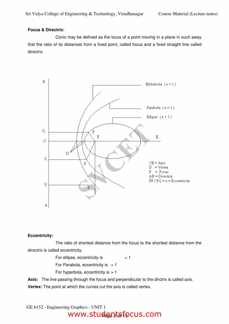
Focus & Directrix:
Conic may be defined as the locus of a point moving in a plane in such away
that the ratio of its distances from a fixed point, called focus and a fixed straight line called
directrix.
Eccentricity:
The ratio of shortest distance from the focus to the shortest distance from the
directrix is called eccentricity.
For ellipse, eccentricity is < 1
For Parabola, eccentricity is = 1
For hyperbola, eccentricity is > 1
Axis: The line passing through the focus and perpendicular to the dirctrix is called axis.
Vertex: The point at which the curves cut the axis is called vertex.
Sri Vidya College of Engineering & Technology, Virudhunagar Course Material (Lecture notes)
GE 6152 - Engineering Graphics - UNIT 1
Page 2 of 15
SVCET
www.studentsfocus.com
CONSTRUCTION OF ELLIPSE:
1. Draw an ellipse when the distance between the focus and directrix is 50mm
and eccentricity is 2/3.
Procedure:
¾ Draw a perpendicular line AB (directrix) and a horizontal line CE (axis).
¾ Mark the focus point F on the axis line 50mm from the directrix.
¾ Divide the CF in to 5 equal parts.
¾ As per the eccentricity mark the vertex ′V′ in the second division of CF
¾ Draw a perpendicular line from vertex V and mark the point ′G′ with the distance VF.
¾ Join the points C& G and extend the line. Similarly mark the point G1 below the axis
line.
¾ Now join the points C& G1 and extend it.
¾ Draw number of smooth vertical lines 1,2,3,4,5,6,etc., as shown in figure.
¾ Now mark the points 1′, 2′, 3′, 4′, 5′…
¾ Take the vertical distance of 11′ and with F as center draw an arc cutting the vertical
line 11′ above and below the axis.
¾ Similarly draw the arcs in all the vertical lines (22′, 33′, 44′…)
¾ Draw a smooth curve through the cutting points to get the required ellipse by free
hand.
Sri Vidya College of Engineering & Technology, Virudhunagar Course Material (Lecture notes)
GE 6152 - Engineering Graphics - UNIT 1
Page 3 of 15
SVCET
www.studentsfocus.com
CONSTRUCTION OF PARABOLA:
2. Construct a parabola when the distance of the focus from the directrix is 40mm.
Note: Eccentricity, e = 1.
Procedure:
¾ Draw a perpendicular line AB (directrix) and a horizontal line CE (axis).
¾ Mark the focus point F on the axis line 40 mm from the directrix.
¾ Divide the CF in to 2 equal parts.
¾ As per the eccentricity mark the vertex ′V′ in the mid point of CF
¾ Draw a perpendicular line from vertex V and mark the point ′G′ with the distance VF.
¾ Join the points C& G and extend the line. Similarly mark the point G1 below the axis
line.
¾ Now joint the points C& G1 and extend it.
¾ Draw number of smooth vertical lines 1,2,3,4,5,6,etc., as shown in figure.
Sri Vidya College of Engineering & Technology, Virudhunagar Course Material (Lecture notes)
GE 6152 - Engineering Graphics - UNIT 1
Page 4 of 15
SVCET
www.studentsfocus.com
¾ Now mark the points 1′, 2′, 3′, 4′, 5′…
¾ Take the vertical distance of 11′ and with F as center draw an arc cutting the vertical
line 11′ above and below the axis.
¾ Similarly draw the arcs in all the vertical lines (22′, 33′, 44′…)
¾ Draw a smooth curve through the cutting points to get the required parabola by free
hand.
CONSTRUCTION OF HYPERBOLA:
3. Draw a hyperbola when the distance of the focus from the directrix is 60 and
eccentricity is 4/3.
Procedure:
¾ Draw a perpendicular line AB (directrix) and a horizontal line CE (axis).
¾ Mark the focus point F on the axis line 40 mm from the directrix.
¾ Divide the CF in to 2 equal parts.
¾ As per the eccentricity mark the vertex V, in the third division of CF
Sri Vidya College of Engineering & Technology, Virudhunagar Course Material (Lecture notes)
GE 6152 - Engineering Graphics - UNIT 1
Page 5 of 15
SVCET
www.studentsfocus.com
¾ Draw a perpendicular line from vertex V, and mark the point G, with the distance VF.
¾ Join the points C& G and extend the line. Similarly mark the point G1 below the axis
line.
¾ Now join the points C& G1 and extend it.
¾ Draw number of smooth vertical lines 1,2,3,4,5,6,etc., as shown in figure.
¾ Now mark the points 1′, 2′, 3′, 4′, 5′…
¾ Take the vertical distance of 11′ and with F as center draw an arc cutting the vertical
line 11′ above and below the axis.
¾ Similarly draw the arcs in all the vertical lines (22′, 33′, 44′…)
¾ Draw a smooth curve through the cutting points to get the required hyperbola by free
hand.
CYCLOIDAL CURVES:
9 Cycloidal curves are generated by a fixed point on the circumference of a circle,
which rolls without slipping along a fixed straight line or a circle.
9 In engineering drawing some special curves (cycloidal curves) are used in the
profile of teeth of gear wheels.
9 The rolling circle is called generating circle.
9 The fixed straight line or circle is called directing line or directing circle.
CYCLOIDS:
Cycloid is a curve generated by a point on the circumference of a circle which rolls
along a straight line.
Epicycloidal:
An epicycloidal is a curve generated by a point on the circumference of a circle,
which rolls without slipping along another circle outside it.
Hypocycloidal:
Hypo-is a curve generated by a point on the circumference of a circle, when the circle
rolls along another circle inside it.
Sri Vidya College of Engineering & Technology, Virudhunagar Course Material (Lecture notes)
GE 6152 - Engineering Graphics - UNIT 1
Page 6 of 15
SVCET
www.studentsfocus.com
1. Construct a cycloid when the diameter of the generating circle is 40 mm.
Procedure:
¾ Draw a circle with diameter 40mm and mark the center O.
¾ Divide the circle in to 12 equal parts as 1,2,3…12.
¾ Draw horizontal line from the bottom points of the circle, with the distance equal to
the circumference of the circle (ПD) and mark the other end point B.
¾ Divide the line AB in to 12 equal parts. (1′, 2′, 3′…12′)
¾ Draw a horizontal line from O to C and mark the equal distance point O1, O2,
O3…O12.
¾ Draw smooth horizontal lines from the points 1,2,3…12.
¾ When the circle starts rolling towards right hand side, the point 1coincides with 1′ at
the same time the center O moves to O1.
¾ Take OA as radius, O1 as center draw an arc to cut the horizontal line 1 to mark the
point a1.
¾ Similarly O2 as center and with same radius OA draw an arc to cut the horizontal line
2 to mark the point a2.
¾ Similarly mark a3, a4…a11.
¾ Draw a smooth curve through the points a1, a2, a3,…. a11, B by free hand.
¾ The obtained curve is a cycloid.
Sri Vidya College of Engineering & Technology, Virudhunagar Course Material (Lecture notes)
GE 6152 - Engineering Graphics - UNIT 1
Page 7 of 15
SVCET
www.studentsfocus.com
ORTHOGRAPHIC PROJECTIONS
In orthographic projections, the principle views – Front view, Top view, & Side
views of an object are drawn by the direct observation. These views are drawn from the pictorial view of an object. The pictorial view is a three dimensional representation. By observing pictorial view, it is very easy to visualize the shape when the object is viewed from front, top & sides.
REPRESENTATION OF ORTHOGRAPHIC VIEWS
Consider a pictorial view as shown in the above diagram, to draw the orthographic views. Assume different surfaces – A, B, C, D, E, & F.
By visualizing the given pictorial view, identify the following principle views – Front view, Top view, left side view and Right side view.
Sri Vidya College of Engineering & Technology, Virudhunagar Course Material (Lecture notes)
GE 6152 - Engineering Graphics - UNIT 1
Page 8 of 15
SVCET
www.studentsfocus.com
[1] Draw the front view , top view and right side view of the object as shown in fig.
Sri Vidya College of Engineering & Technology, Virudhunagar Course Material (Lecture notes)
GE 6152 - Engineering Graphics - UNIT 1
Page 9 of 15
SVCET
www.studentsfocus.com
[2] Draw the front view, top view and right side view of the object as shown in fig.
Sri Vidya College of Engineering & Technology, Virudhunagar Course Material (Lecture notes)
GE 6152 - Engineering Graphics - UNIT 1
Page 10 of 15
SVCET
www.studentsfocus.com
[3] Draw the front view, top view and right side view of the object as shown in fig.
Sri Vidya College of Engineering & Technology, Virudhunagar Course Material (Lecture notes)
GE 6152 - Engineering Graphics - UNIT 1
Page 11 of 15
SVCET
www.studentsfocus.com
Sri Vidya College of Engineering & Technology, Virudhunagar Course Material (Lecture notes)
GE 6152 - Engineering Graphics - UNIT 1
Page 12 of 15
SVCET
www.studentsfocus.com
Sri Vidya College of Engineering & Technology, Virudhunagar Course Material (Lecture notes)
GE 6152 - Engineering Graphics - UNIT 1
Page 13 of 15
SVCET
www.studentsfocus.com
Sri Vidya College of Engineering & Technology, Virudhunagar Course Material (Lecture notes)
GE 6152 - Engineering Graphics - UNIT 1
Page 14 of 15
SVCET
www.studentsfocus.com
Sri Vidya College of Engineering & Technology, Virudhunagar Course Material (Lecture notes)