J. Me&. Phys. Solids, 1968, Vol. 16, pp. 1 to 12. Pergamon Press. Printed in Gnat Britain. PLANE STRAIN DEFORMATION NEAR A CRACK TIP IN A POWER-LAW HARDENING MATERIAL By J. R. RICE and G. F. ROSENGREN Division of Engineering, Brown University, Providence, Rhode Island (ZZectiued 81st August 1967) CRACK-TIP strain singularities are investigated with the aid of an energy line integral exhibiting path independence for all contours surrounding a crack tip in a two-dimensional deformation field of an elastic material (or elastic/plastic material treated by a deformation theory). It is argued that the product of stress and strain exhibits a singularity varying inversely with distance from the tip in all materials. Corresponding near crack tip stress and strain fields are obtained for the plane straining of an incompressible elastic/plastic material hardening according to a power law. A noteworthy feature of the solution is the rapid rise of triaxial stress concentration above the flow stress with increasing values of the hardening exponent. Results are presented graphically for a range of hardening exponents, and the interpretation of the solution is aided by a discussion of analogous results in the better understood anti-plane strain case. 1. INTRODUCTION ELASTIC/PLASTIC analyses of deformation fields near cracks are of obvious relevance to the mechanics of fracture. Little progress has been made on the important problems of tensile loadings opening a crack, although the anti-plane strain case is now well understood for both perfectly plastic (HULT and MCCLINTOCK 1956) and strain hardening (NEUBER 1961; RICE 1967a) materials, and some useful approximate models (DUGDALE 1960; RICE 1967b) have been proposed for tensile cases. A recent analytical technique developed by RICE (1967c) identifies a line integral which has the same value for all paths encircling the tip of a crack or flat surfaced notch in two dimensional deformation fields of linear or non-linear elastic materials. Appropriate choices of the integration path have led to approximate estimates of strain concentrations for a variety of notch problems; we here employ the method as a starting point in the analysis of near crack tip deformation fields in the plane straining of materials which harden according to a power law relation between stress and strain. Let c denote the energy density of an elastic material. Then considering a homogeneous body of this material containing a traction free crack and subjected to a two- dimensional deformation field (Fig. 1, all stresses depend only on a: and y), the line integral 1
Transcript
J. Me&. Phys. Solids, 1968, Vol. 16, pp. 1 to 12. Pergamon Press. Printed in Gnat Britain.
PLANE STRAIN DEFORMATION NEAR A CRACK TIP
IN A POWER-LAW HARDENING MATERIAL
By J. R. RICE and G. F. ROSENGREN
Division of Engineering, Brown University, Providence, Rhode Island
(ZZectiued 81st August 1967)
CRACK-TIP strain singularities are investigated with the aid of an energy line integral exhibiting path independence for all contours surrounding a crack tip in a two-dimensional deformation field of an elastic material (or elastic/plastic material treated by a deformation theory). It is argued that the product of stress and strain exhibits a singularity varying inversely with distance from the tip in all materials. Corresponding near crack tip stress and strain fields are obtained for the plane straining of an incompressible elastic/plastic material hardening according to a power law. A noteworthy feature of the solution is the rapid rise of triaxial stress concentration above the flow stress with increasing values of the hardening exponent. Results are presented graphically for a range of hardening exponents, and the interpretation of the solution is aided by a discussion of analogous results in the better understood anti-plane strain case.
1. INTRODUCTION
ELASTIC/PLASTIC analyses of deformation fields near cracks are of obvious relevance to the mechanics of fracture. Little progress has been made on the important problems of tensile loadings opening a crack, although the anti-plane strain case is now well understood for both perfectly plastic (HULT and MCCLINTOCK 1956) and strain hardening (NEUBER 1961; RICE 1967a) materials, and some useful approximate models (DUGDALE 1960; RICE 1967b) have been proposed for tensile cases. A recent analytical technique developed by RICE (1967c) identifies a line integral which has the same value for all paths encircling the tip of a crack or flat surfaced notch in two dimensional deformation fields of linear or non-linear elastic materials. Appropriate choices of the integration path have led to approximate estimates of strain concentrations for a variety of notch problems; we here employ the method as a starting point in the analysis of near crack tip deformation fields in the plane straining of materials which harden according to a power law relation between stress and strain.
Let c
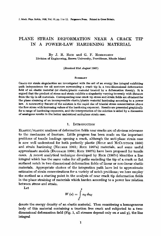
denote the energy density of an elastic material. Then considering a homogeneous body of this material containing a traction free crack and subjected to a two- dimensional deformation field (Fig. 1, all stresses depend only on a: and y), the line integral
1
J. R. RICE and G. F. ROSENWEN
FIG. 1. Coordinates for description of crack tip deformation field, and typical contour r for evaluation of path-independent line integral.
J= S[ W (e) dy - T . g ds 1
r
(1)
has the same value for all paths r surrounding the tip. Here the path is traversed in the contra-clockwise sense, T is the traction vector on r defined according to the outward normal, Tg = ofj q, u is the displacement vector, and s is arc length. Path independence is readily demonstrated in a standard fashion by choosing two separate integration paths I’i and I’s. Since the integrand vanishes on the crack surfaces, JZ - JI is the above integral carried around the boundary of the area between ri and I’s, and a Green-Gauss type transformation of a line integral to an area integral immediately leads to Js - J1 = 0, proving path independence. As no success has been met in finding similar path-independent integrals for incremental elastic/plastic stress-strain relations, we are here forced to consider a deformation theory of plasticity which is in reality a non-linear elasticity. In particular, we consider an incompressible material with a relation between deviatoric stresses and strains of the Mises form
27 a5 = - et5
Y
where T = 2/(& stj ~$5) and y = d(2~~g ~(5) and with the hardening following a power law of the form
T = Gy = TO y for y < 70
YN
0
(3) 7=70 - for Y 2 ~0.
YO
Here 70, ys are the yield stress and strain in shear, and N is the hardening exponent. As our concern will be only with the near crack tip strain singularity, incompressi- bility is not expected to be a poor approximation for moderate strain hardening as plastic strains are incompressible. Also, the resulting near tip solution involves proportional flow so that a deformation theory is less objectionable than is usually the case.
The utility of the path independent integral lies largely in the fact that its value may be simply determined for a variety of cases and configurations (RICE
1967c). For example, the integral has the same value as for the linear elastic solution to a given problem when the yield zone is small compared to geometric
Plane strain deformation near a crack tip in a power-law hardening material 3
dimensions of the problem. This is because such small-scale yielding solutions may be obtained through a boundary layer approach (RICE 1967a, b) in which actual boundary conditions are replaced by the requirement of an asymptotic approach to IRWIN’S (1960) characteristic linear-elastic inverse-square-root stress distribution at large distances from the tip. An extension of the integration path to infinity then requires that only the asymptotically approached field contributes, and the small-scale yielding value of J is
J = (I - “2) K1s E * (4)
Here RI is Irwin’s stress intensity factor, and for the wellknown problem of a crack of length 2a subjected to a uniform remote tension uaD
J= 7F (1 - “2) 02, a
E ’ (5)
Approximate evaluations of J for large-scale yielding are possible due to the relation of the line integral to the rate of variation of equilibrium potential energy of a crack body with respect to crack length. One such approximation is given and others are suggested by RICE (1967c).
2. CRACK TIP SINGULARITIES
Choosing a circular path of radius r for the evaluation of J, (1) becomes
+lr
J -= T Si W [e (r, B)] cos 6’ - T (r, 6’) . g h s)} de.
--II
03)
Evidently the bracketed integrand { . . . } must exhibit a singularity at the crack tip which, at least in its angular average, depends inversely on distance from the tip. Since all terms within the integrand are of order stress times strain (assuming rotations to be of the same order as strains) one is tempted to conclude that crack problems in all materials result in a l/r singularity in the product of stress and strain :
a function of 0 =cj EZJ +-
as r 3 o .
r (7)
While attempts at a rigorous proof of this assertion have not been successful, its validity in solved cases is noteworthy. The inverse-square-root linear-elastic stress singularities are in agreement, as is also an approximate analysis of perfectly plastic plane strain (RICE 1967c) where a l/r strain singularity results from the centred fan slip line field (HILL 1950) characteristic of analogous punch problems. Further, the validity of (7) may be verified in all elastic/plastic anti-plane strain crack solutions (RICE 1967a).
For power law hardening materials, (7) implies near crack tip stress and strain distributions of the form
4 J. R. RICE and G. F. ROSENCREN
Conversely, we may turn our procedure around and prove the following. If stress
and strain components have the singular structure of powers of r times functions
of 0, then traction-free crack-surface boundary conditions (which lead directly to
path independence) may be satisfied only if the powers of r are as in (8). This
converse procedure is essentially a concise adaption of WILLIAMS’ (19%) eigen-
function expansion to the non-linear case, but here we determine the eigenvalue
(exponent of r) directly, and have left only the problem of determining the
corresponding eigenfunction.
To achieve this latter task, we introduce an Airy stress function U to satisfy
equilibrium and give the correct dependence on T :
u = (I + V2
z+N T(2+iv)/u+N)f(e)_
Near crack tip stresses are then
1 au 1 22 u arr=-_++-
r br r2 382
= (1 + N) r-N’(i+N) f(Q) +
(9)
1 (10)
In a similar fashion, incompressibility and strain compatibility are satisfied by
(W . The functions f (8), g (0) are not independent, but must be chosen to satisfy the one independent stress-strain relation of (2) and the hardening law (3), giving the
following two equations.
Plane strain deformation near a crack tip in a power-law hardening material 5
Note that the governing differential equation for f (8) has an equi-dimensional character, in the sense that if f (0) is a solution, then so is any constant times f (8). The unknown multiplicative constant is determined in terms of the value J of the path-independent integral by inserting our solution into (6). The equation is solved over the interval 0, w subject to boundary conditions which ensure a solution corresponding to symmetric deformations relative to the crack line. Note that f (0) may be chosen arbitrarily, say as
f(O) = 1, (17)
with the solution subject to a later normalization. Symmetry requires that 0~0, dar,./3Q, and 3as&M? all vanish on B = 0, leading to two further conditions
f’(0) =f’“(O) =o. (18)
Finally, traction-free crack surfaces require age and u,.e to vanish at 0 = V, so that
f(n)=f’(?T)=O. (19)
Five boundary conditions appear at fist sight to overspecify the fourth order equation for f (Q). Actually, they do not, for the two conditions at 8 = 7~ imply one another. This is because the assumed forms of dependence on T in (9) and (11)
necessarily result in path independence for the integral J and, recalling the proof of path independence sketched out in the introduction, this means that
T (T, n) . g (r, m) = - age (T, T) sue;; p, +ure(r,7r)aUrpL0 c3-3)
for all solutions of the equation for f (0). Thus the vanishing of a,.~ on the crack surface implies the vanishing of 060.
J. R. RICE and G. F. ROSEN~REN
3. NUMERICAL COMPUTATIONS AND GRAPHICAL RESULTS
For the numerical solution of the differential equation (15) forf, a fourth-order Runge-Kutta integration was used. Since this method can only be used for initial value problems, and ours is a two-point problem, as seen from the boundary con- ditions (17), (18) and (19), starting values off” (0) had to be guessed until two values off” (0) were found, one giving f(~) < 0 and the other giving f(r) > 0, and a linear interpolation procedure could be used. After some trial runs a step size equal to 0.9’ was found to be a good choice and for all values of N, except for N > 0.9, rapid convergence was obtained. For N > O-9 the solutions were very sensitive to changes inf” (0), reflecting the breakdown of (15) for N = 1, in which case one obtains expressions of the form O/O. Consequently, instead of using the interpolation procedure where N > 0.9, the appropriate interval for f” (0) in these cases was run through by using small increments in f” (0) and the right solution was chosen by inspection of the results.
Because of the complicated form of the differential equation forf (e), no attempts have been made to make any error estimates of the numerical calculations. How- ever, since all results for N = 1, in which case the analytic solution is easily obtained, are very close to the results for N = 0.99, as can be seen from the figures, it is believed that the numerical results can be accepted with great confidence.
In determining the correct multiplicative constant for f (O), i.e. performing the integration of (6), a g-point formula was used.
All computations were performed on an IBM-360 and the average computing time for a run was 3.5 min.
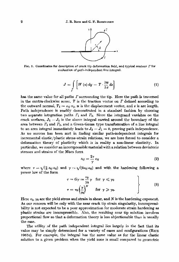
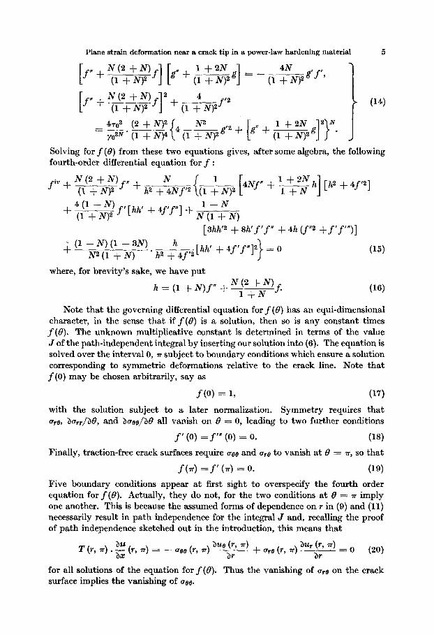
The power hardening law (3) has been drawn for some different values of the hardening exponent N (Fig. 2).
T/TO= y/y0 FOR y < y.
0.5 ~/To=(~/~o)NFOR y > y.
Fro. 2. Power hardening law.
From the expressions for the Mises equivalent shear stress T and shear strain y one finds
7. = TO [R (B)/r]Nl(l+N), y = y,, [R (~‘)/T]~“+N (21)
Plane strain deformation near a crack tip in a power-law hardening material 7
where R (0) is an expression containing f (0) and its derivatives, or, when using the normalized form off(Q), R = R (8; J, N).
From (21) one immediately sees that R (0) gives the shape of constant equivalent strain lines very near the crack tip and that R (6) can be interpreted as an approxi- mate indication of the distance from the crack tip to the elastic/plastic boundary (approximate since our solution gives the singular term only, and not of necessity the complete solution in the plastic region). Figures 3 and 4 show the nondimensional distance ys 70 R (0)/J for different values of N; the latter figure amplifies detail near the crack tip through a twenty-five times larger scale. In these figures the extreme closeness between the results for N = 1 and 0.99 is readily seen.
FIG. 3. Approximate location of elastic/plastic boundary and geometrical shape of constant equivalent shear lines very near the crack tip.
@ N = 0.005 @ N= 0.2
0 0.01 @ 0.3 0 0.05 g 0.5
co 0. I 1,0.99
FIG. 4. Elastic/plastic boundary; detail very near tip.
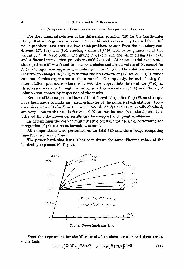
In Figure 5 it is demonstrated how the elastic/plastic boundary in front of and behind the crack tip strongly depends on the hardening exponent. In this figure is also shown how the maximum distance from the crack tip to the elastic/plastic boundary, ys TO R-=/J, varies with N.
J. R. R.ICE and G. F. ROSEN~REN
I
0.3
0 0.5 I.”
Fxo. 6. Distance from crack tip to approximate elastic/plastic boundary in f’ront of and
behind the crack, as well as maximum distance from crack tip to boundary.
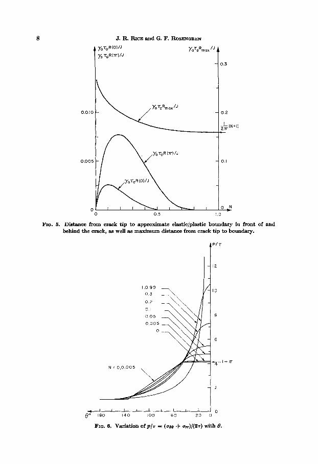
t P/i-
Ii 12
I-l
N
I.0 99
0.3 -
0.2
0. I \
\ “,.::5 z\
1+7T
---J---o 8’ 180 140 100 60 20 0
FIG. 6. Variation of P/T = (age + CT,,)/(%) with 8.
Plane strain deformation near a crack tip in a power-law hardening material 9
Using the expressions for the stresses one easily finds that the mean stress, p = (age + ~,~)/2 divided by 7 is a function of 0 only. Figure 6 shows this B-variation of p/r together with the mean stress distribution in the perfectly plastic case, N = 0. The latter distribution is easily obtained from the condition of two regions of constant stress state, one in front and one behind the crack tip, with the regions being built up of isosceles right triangles thus forcing any slip line leaving the crack surface and ending up at the symmetry line in front of the crack tip to swing through an angle of 4, giving P/T = 1 + TI at 8 = 0 (HILL
1950; RICE 1967c). In this figure again is demonstrated the closeness of the results for N = 1 and 0.99 as well as of the results for N = 0.005 and N = 0.
,I 1 I I I I I I *N
0 0.2 0.4 0.6
Bm. 7. Maximum normal stress to equivalent stress for 0 = 0, o42~)/e=o, vs. N.
Figure 7 shows how the ratio of the maximum normal stress to the equivalent stress along the symmetry line ahead of the crack, ag,s/271,3,c, varies with the hardening exponent. The rapid rise over the (1 + 4~) value anticipated from perfect plasticity is notable and of interest when, for instance, discussing fracture.
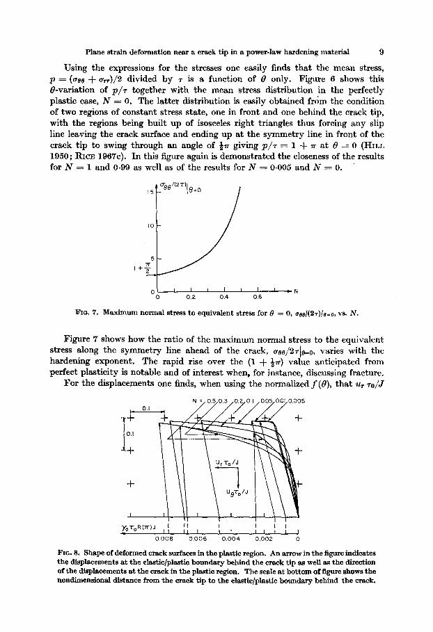
For the displacements one finds, when using the normalized f (B), that u,. TO/J
Y,T,,R(TlJ 1 I I I
e I 1 I 1 I J
0 006 0.006 0.004 0.002 0
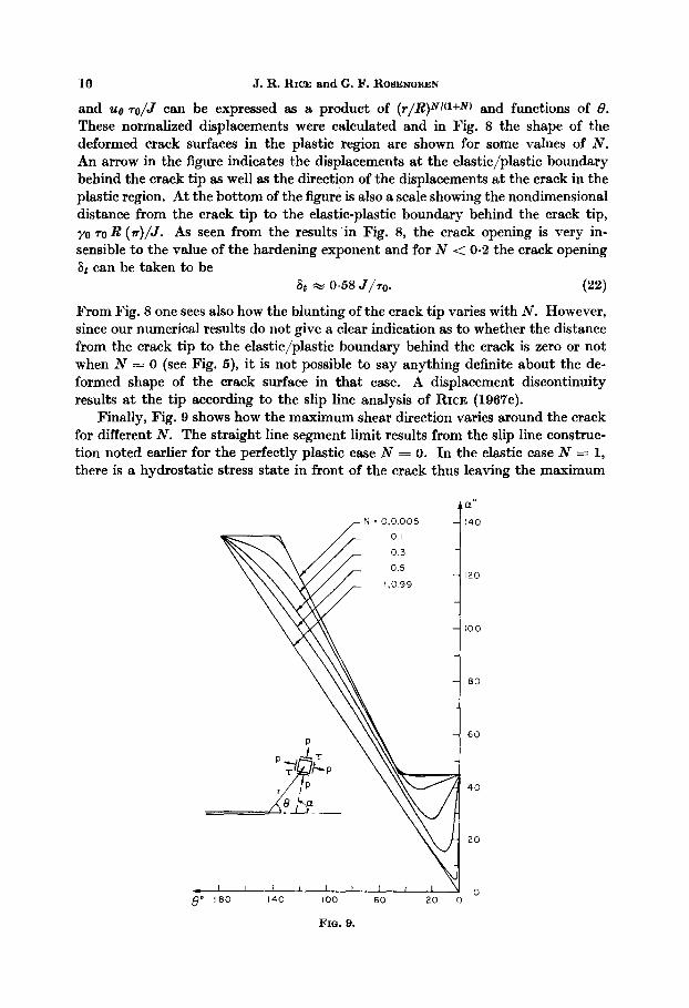
FIG. 8. Shape of deformed crack surfaces in the plastic region. An arrow in the figure indicates the displacements at the elastic/plastic boundary behind the crack tip as well as the direction of the displacements at the crack in the plastic region. The scale at bottom of figure shows the nondimensional distance from the crack tip to the ehxstic/plastic boundary behind the crack.
10 J.R. RICE andG. I?. ROBENGREN
and ue TO/J can be expressed as a product of (r/R)N’(l+N) and functions of 8. These normalized displacements were calculated and in Fig. 8 the shape of the deformed crack surfaces in the plastic region are shown for some values of N. An arrow in the figure indicates the displacements at the elastic/plastic boundary behind the crack tip as well as the direction of the displacements at the crack in the plastic region. At the bottom of the figure is also a scale showing the nondimensional distance from the crack tip to the elastic-plastic boundary behind the crack tip,
YO 70 R (d/J. A s seen from the results in Fig. 8, the crack opening is very in- sensible to the value of the hardening exponent and for N < 0.2 the crack opening St can be taken to be
6t w o&3 J/T,,. (22)
From Fig. 8 one sees also how the blunting of the crack tip varies with N. However, since our numerical results do not give a clear indication as to whether the distance from the crack tip to the elastic/plastic boundary behind the crack is zero or not when N = 0 (see Fig. 5), it is not possible to say anything definite about the de- formed shape of the crack surface in that case. A displacement discontinuity results at the tip according to the slip line analysis of RICE (1967c).
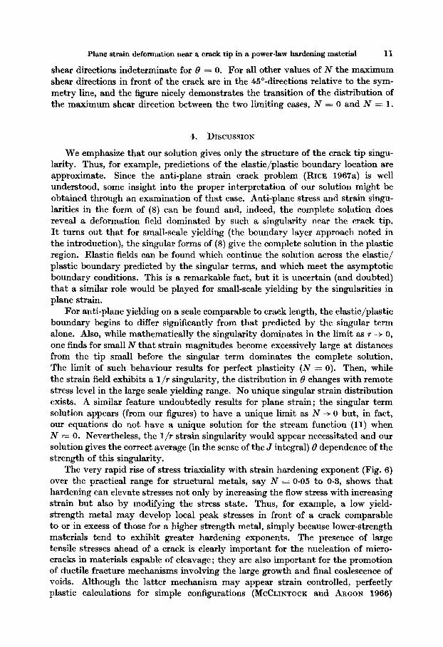
Finally, Fig. 9 shows how the maximum shear direction varies around the crack for different N. The straight line segment limit results from the slip line construc- tion noted earlier for the perfectly plastic case N = O. In the elastic case N = 1, there is a hydrostatic stress state in front of the crack thus leaving the maximum
aa ,wN = 0.0.005 140
120
100
80
60
40
20
I I I I I 1 I , I
8” 180 140 100 60 20 0
FIG. 9.
Plane strain deformation near a crack tip in a power-law hardening material 11
shear directions indeterminate for f3 = 0. For all other values of N the maximum shear directions in front of the crack are in the 450-directions relative to the sym- metry line, and the figure nicely demonstrates the transition of the distribution of the maximum shear direction between the two limiting cases, N = 0 and N = 1.
4. DISCUSSION
We emphasize that our solution gives only the structure of the crack tip singu- larity. Thus, for example, predictions of the elastic/plastic boundary location are approximate. Since the anti-plane strain crack problem (RICE 1967a) is well understood, some insight into the proper interpretation of our solution might be obtained through an examination of that case. Anti-plane stress and strain singu- larities in the form of (8) can be found and, indeed, the complete solution does reveal a deformation field dominated by such a singularity near the crack tip. It turns out that for small-scale yielding (the boundary layer approach noted in the introduction), the singular forms of (8) give the complete solution in the plastic region. Elastic fields can be found which continue the solution across the elastic/ plastic boundary predicted by the singular terms, and which meet the asymptotic boundary conditions. This is a remarkable fact, but it is uncertain (and doubted) that a similar role would be played for small-scale yielding by the singularities in plane strain.
For anti-plane yielding on a scale comparable to crack length, the elastic/plastic boundary begins to differ significantly from that predicted by the singular term alone. Also, while mathematically the singularity dominates in the limit as r + 0, one finds for small N that strain magnitudes become excessively large at distances from the tip small before the singular term dominates the complete solution. The limit of such behaviour results for perfect plasticity (N = 0). Then, while the strain field exhibits a l/r singularity, the distribution in 8 changes with remote stress level in the large scale yielding range. No unique singular strain distribution exists. A similar feature undoubtedly results for plane strain; the singular term solution appears (from our figures) to have a unique limit as N --f 0 but, in fact, our equations do not have a unique solution for the stream function (11) when N = 0. Nevertheless, the l/r strain singularity would appear necessitated and our solution gives the correct average (in the sense of the J integral) B dependence of the strength of this singularity.
The very rapid rise of stress triaxiality with strain hardening exponent (Fig. 6) over the practical range for structural metals, say N = 0.05 to 0.3, shows that hardening can elevate stresses not only by increasing the flow stress with increasing strain but also by modifying the stress state. Thus, for example, a low yield- strength metal may develop local peak stresses in front of a crack comparable to or in excess of those for a higher strength metal, simply because lower-strength materials tend to exhibit greater hardening exponents. The presence of large tensile stresses ahead of a crack is clearly important for the nucleation of micro- cracks in materials capable of cleavage; they are also important for the promotion of ductile fracture mechanisms involving the large growth and final coalescence of voids. Although the latter mechanism may appear strain controlled, perfectly plastic calculations for simple configurations (MCCLINTOCK and ARGON 1966)
12 J. R. RICE and G. F. RO~EN~REN
show a nearly exponential dependence of the rate of void growth per unit of overall strain on the ratio of mean normal stress to yield stress. The role of strain hardening in slowing void growth and raising strains required for coalescence cannot presently be assessed, so that a direct step from this analysis to a crack extension criterion will require further work. Finite geometry changes at the crack tip also influence the deformation state in separation prone material. For example, analyses in the perfectly plastic case do not lead to large strains directly ahead of the crack unless progressive blunting of the tip is considered (RICE 1967c). Another complicating
feature is the distinction that must be made between strain increments due to load
elevation and strain increments due to crack advance in incremental elastic/plastic
materials (MCCLINTOCK and IRWIN 1965). Ductile metals exhibit at least a limited amount of stable crack extension prior to catastrophic fracture. The pertinent question in fracture mechanics is more one as to the prediction of final instability than to the prediction of the initiation of crack extension. While the adequate modelling of fracture remains remote, our present solution should be useful for the further understanding of the effects of yielding and hardening, providing other pertinent features of the problem are kept in mind.
We have learned by private communication that Professor J. W. Hutchinson is conducting similar work on the structure of crack tip singularities, both in plane strain and plane stress, basing his approach on a direct computer-assisted adaption of the Williams eigenvalue technique to the non-linear case. He too finds a l/r
variation of stress times strain for both deformation modes. Also, Professor J. L. Swedlow reports that a further analysis of experimentally determined plane-stress crack-tip deformation fields, with data obtained by GERBERICH (1964), tends to
support a l/r dependence for the product of stress and strain near a crack tip.
ACKNOWLEDGMENTS
Grateful acknowledgement for support of this work is made to the Advanced Research Pro- jects Agency (Contract SD-86 with Brown University), and to the National Science Foundation (facilities grant GP-4825) for the support of computer time.
DUGDALE, D.S. 1060 GERBERICE, W. W. 1964 HILL, R. 1950
HULT, J. A. and MCCLINTOCK, F. A. 1956
IRWIN, G. R. 1960
MCCLINTOCK, F. A. and ARGON, A. S.
MCCLINTOCK, F. A. and IRWIN, G. R.
NEWER, H. RICE, J. R.
1966
1965
1961 1967s 1967b
196’7~ Brown University ARPA SD-86 Report E39. WILLIAMS, M. L. 1957 J. Appl. Mech. 24, 109.
REzBRENCES
J. Me&. Phys. Solids 8, 100. Exp. Mech. 4, 835. The Mathematical Theory of Plasticity (Clarendon Press,
Oxford).
Proc. Ninth International Congress Appl. Mech. 8, 51. Structural Mechanics, p. 557. (Edited by GOODIER, J. N.
and HOFF, N. J., Pergamon Press, New York). Mechanical Behauiour of Materials (Addison Wesley,
Reading, Mass.). Symposium on Fracture Toughness, Am. Sot. Test. Mater.,
STP-881, 84. J. Appl. Mech. 28, 544. J. Appl. Mech. 34, 237. Symposium on Fatigue Crack Growth, Am. Sot. Test. Mater.