.G@eering Fracture Mechanics Vol. 35, No. 6, pp. 1105-1116, 1990 0013-7944/90 s3.00 + 0.00 Printed in Great Britain. 0 1990 Fkrgamoo press pk. PLANE-STRESS CRACK-TIP FIELDS FOR PRESSURE-SENSITIVE DILATANT MATERIALS F. Z. LI and J. PAN Department of Mechanical Engineering and Applied Mechanics, The University of Michigan, Ann Arbor, MI 48109-2125, U.S.A. Abstraet--In this paper we present plane-stress crack-tip stress and strain fields for pressure-sen- sitive dilatant materials. A hydrostatic stress-dependent yield criterion and the normality flow rule are used to account for pressure-sensitive yielding and plastic dilatancy. The material hardening response is specified by a power-law relation. The plane-stress mode I singular fields are found in a separable form similar to the HRR fields (Hutchinson, J. Mech. Phys. Solids 16, 13-31 and 337-347, 1968; Rice and Rosengren, J. Mech. Phys. Solids 16, l-12, 1968). ‘Ihe angular variations of the fields depend on the material hardening exponent and the pressure sensitivity parameter. Our low-hardening solutions for d&rent degrees of pressure sensitivity agree well with the correspond- ing perfectly plastic solutions. An important aspect of the eRecta of pressure.-sensitive yielding and plastic dilatancy on crack-tip fields is the lowering of the opening stress and the hydrostatic stress directly ahead of the crack tip. This effect, similar to that under plane-strain conditions (Li and Pan, to appear in J. Appl. Mech. 1989), has implications in the material toughening observed in some ceramic and polymeric composites. 1. INTRODUCTION RECENTLY, toughened structural polymers and ceramics have attracted tremendous research attention due to their outstanding mechanical properties. Experimental results on the mechanical behavior of these two classes of materials support a constitutive description that accounts for pressure-sensitive yielding and plastic dilatancy. For example, Spitzig and Richmond[ l] observed that for polymeric materials (polyethylene and polycarbonate) the flow stress has a significant dependence on the hydrostatic stress. Carapellucci and Yee[2] performed biaxial tension tests on glassy bisphenol A-polycarbonate and found that a modified Mises yield criterion with a dependence on the hydrostatic stress fits their experimental data well. Later, Sue and Yee[3] investigated the toughening mechanisms in a multi-phase alloy of Nylon 6,6/Polyphenylene oxide and found that there is a considerable amount of plastic volumetric change in the composite material due to the formation of crazes at large strain. The phenomenon of pressure-sensitive yielding is also observed in transformation-toughened ceramics (for example, see Chen and Reyes Morel[4] and Reyes Morel and Chen[5]). According to these studies, pressure-sensitive yielding seems to play an important role in the plastic deformation and fracture of toughened polymers and in the transformation plasticity and fracture of toughened ceramics. From the viewpoint of phenomenological fracture mechanics, the initiation and growth of a crack depend on the surrounding stress and deformation fields near the tip. Therefore, analyses of the crack-tip stress and deformation fields are needed to relate continuum stress analyses to micromechanical failure mechanisms. The asymptotic crack-tip fields for power-law hardening Mises materials (the well-known HRR fields) have been presented by Hutchinson[6,7] and Rice and Rosengren[8]. The crack-tip fields for power-law hardening orthotropic materials can be found in Pan and Shih[9, lo]. The deformations of all these fields are volume-preserving. An example of the HRR type crack-tip fields with volumetric deformation was presented by Hutchinson[l l] for power-law creep materials undergoing creep-constrained grain boundary cavitation. Recently, Li and Pan[l2] obtained the crack-tip stress and strain fields for pressure-sensitive dilatant materials under plane-strain condition. In this study, we investigate the plane-stress crack-tip fields for pressure-sensitive dilatant materials. A simple hydrostatic stress-dependent yield criterion and the normality flow rule are used to account for the pressure-sensitive yielding and plastic dilatancy (Li and Pan[l2]). Mode I crack-tip fields for both power-law hardening and perfectly plastic materials are obtained. The hardening solutions of the fields depend on the pressure sensitivity parameter cc and have a separable form. When ~1 = 0, they exactly match the HRR results. The low-hardening solutions 1105
Transcript
.G@eering Fracture Mechanics Vol. 35, No. 6, pp. 1105-1116, 1990 0013-7944/90 s3.00 + 0.00 Printed in Great Britain. 0 1990 Fkrgamoo press pk.
PLANE-STRESS CRACK-TIP FIELDS FOR PRESSURE-SENSITIVE DILATANT MATERIALS
F. Z. LI and J. PAN
Department of Mechanical Engineering and Applied Mechanics, The University of Michigan, Ann Arbor, MI 48109-2125, U.S.A.
Abstraet--In this paper we present plane-stress crack-tip stress and strain fields for pressure-sen- sitive dilatant materials. A hydrostatic stress-dependent yield criterion and the normality flow rule are used to account for pressure-sensitive yielding and plastic dilatancy. The material hardening response is specified by a power-law relation. The plane-stress mode I singular fields are found in a separable form similar to the HRR fields (Hutchinson, J. Mech. Phys. Solids 16, 13-31 and 337-347, 1968; Rice and Rosengren, J. Mech. Phys. Solids 16, l-12, 1968). ‘Ihe angular variations of the fields depend on the material hardening exponent and the pressure sensitivity parameter. Our low-hardening solutions for d&rent degrees of pressure sensitivity agree well with the correspond- ing perfectly plastic solutions. An important aspect of the eRecta of pressure.-sensitive yielding and plastic dilatancy on crack-tip fields is the lowering of the opening stress and the hydrostatic stress directly ahead of the crack tip. This effect, similar to that under plane-strain conditions (Li and Pan, to appear in J. Appl. Mech. 1989), has implications in the material toughening observed in some ceramic and polymeric composites.
1. INTRODUCTION
RECENTLY, toughened structural polymers and ceramics have attracted tremendous research attention due to their outstanding mechanical properties. Experimental results on the mechanical behavior of these two classes of materials support a constitutive description that accounts for pressure-sensitive yielding and plastic dilatancy. For example, Spitzig and Richmond[ l] observed that for polymeric materials (polyethylene and polycarbonate) the flow stress has a significant dependence on the hydrostatic stress. Carapellucci and Yee[2] performed biaxial tension tests on glassy bisphenol A-polycarbonate and found that a modified Mises yield criterion with a dependence on the hydrostatic stress fits their experimental data well. Later, Sue and Yee[3] investigated the toughening mechanisms in a multi-phase alloy of Nylon 6,6/Polyphenylene oxide and found that there is a considerable amount of plastic volumetric change in the composite material due to the formation of crazes at large strain. The phenomenon of pressure-sensitive yielding is also observed in transformation-toughened ceramics (for example, see Chen and Reyes Morel[4] and Reyes Morel and Chen[5]). According to these studies, pressure-sensitive yielding seems to play an important role in the plastic deformation and fracture of toughened polymers and in the transformation plasticity and fracture of toughened ceramics.
From the viewpoint of phenomenological fracture mechanics, the initiation and growth of a crack depend on the surrounding stress and deformation fields near the tip. Therefore, analyses of the crack-tip stress and deformation fields are needed to relate continuum stress analyses to micromechanical failure mechanisms. The asymptotic crack-tip fields for power-law hardening Mises materials (the well-known HRR fields) have been presented by Hutchinson[6,7] and Rice and Rosengren[8]. The crack-tip fields for power-law hardening orthotropic materials can be found in Pan and Shih[9, lo]. The deformations of all these fields are volume-preserving. An example of the HRR type crack-tip fields with volumetric deformation was presented by Hutchinson[l l] for power-law creep materials undergoing creep-constrained grain boundary cavitation. Recently, Li and Pan[l2] obtained the crack-tip stress and strain fields for pressure-sensitive dilatant materials under plane-strain condition.
In this study, we investigate the plane-stress crack-tip fields for pressure-sensitive dilatant materials. A simple hydrostatic stress-dependent yield criterion and the normality flow rule are used to account for the pressure-sensitive yielding and plastic dilatancy (Li and Pan[l2]). Mode I crack-tip fields for both power-law hardening and perfectly plastic materials are obtained. The hardening solutions of the fields depend on the pressure sensitivity parameter cc and have a separable form. When ~1 = 0, they exactly match the HRR results. The low-hardening solutions
1105
1106 F. Z. LI and J. PAN
for different degrees of pressure sensitivity are found to agree well with the corresponding perfectly plastic solutions.
2. CONSTITUTIVE RELATIONS
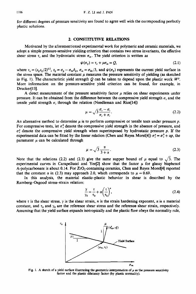
Motivated by the aforementioned experimental work for polymeric and ceramic materials, we adopt a simple pressure-sensitive yielding criterion that contains two stress invariants, the effective shear stress r, and the hydrostatic stress a,,,. The yield criterion is written as
$(a,/) = r, + ~0, = Q, (2.1) where z, = (s~s~/~)‘/~, sii = ci/ - a,6,, a, = akk/3, and rj (a,) represents the current yield surface in the stress space. The material constant p measures the pressure sensitivity of yielding (as sketched in Fig. 1). The characteristic yield strength Q can be taken to depend upon the plastic work W+‘. More information on the pressure-sensitive yield criterion can be found, for example, in Drucker[l3].
A direct measurement of the pressure sensitivity factor p relies on shear experiments under pressure. It can be obtained from the difference between the compressive yield strength cc and the tensile yield strength cr, through the relation (Needleman and Rice[l4])
p=$S. c f
P-2)
An alternative method to determine p is to perform compressive or tensile tests under pressure p. For compressive tests, let a: denote the compressive yield strength in the absence of pressure, and a$ denote the compressive yield strength when superimposed by hydrostatic pressure p. If the experimental data can be fitted by the linear relation (Chen and Reyes Morel[4]) a; = a: + up, the paramater p can be calculated through
p=Jr-. 3+a
(2.3)
Note that the relations (2.2) and (2.3) give the same supper bound of ~1 equal to ,/% The experimental curves in Carapellucci and Yee[2] show that the factor p for glassy bisphenol A-polycarbonate is about 0.14. For Z@containing ceramics, Chen and Reyes Morel[4] reported that the constant tl in (2.3) may approach 2.0, which corresponds to p = 0.69.
In this analysis, the material elastic-plastic behavior in shear is described by the Ramberg-Osgood stress-strain relation:
(2.4)
where T is the shear stress, y is the shear strain, n is the strain hardening exponent, a is a material constant, and r. and y. are the reference shear stress and the reference shear strain, respectively. Assuming that the yield surface expands isotropically and the plastic flow obeys the normality rule,
Fig. 1. A sketch of a yield surface illustrating the geometric interpretation of /1 as the pressure sensitivity factor and the plastic dilatancy factor (by plastic normality).
Plane-stress crack-tip fields for pressure-sensitive dilatant materials 1107
we generalize the relation between the shear stress and the plastic shear strain (the second term on the right-hand side) in (2.4) to multiaxial states. The resulting deformation plasticity relation between the stresses and plastic strains is (Li and Pan[l2])
(2.5)
where rge is the generalized effective shear stress defined by rge = r, + pa,,,. We write the total plastic strain .$ in (2.5) as the sum of a deviatoric part, ~7, and a volumetric
part, &, so that EC = L~F + &!kSij. It can be easily shown that
(2.6)
where 7: = (~E~~E~~)‘/’ is the effective plastic shear strain. Equation (2.6) indicates that the pressure sensitivity factor ~1 also serves as the plastic dilatancy factor, which gives the ratio of plastic VOlUX’tICtriC Strain 6$k t0 the CffeCtiVe plastic shear Strain 7:.
For the analysis of a crack under mode I loading, it is more convenient to express the constitutive equation in terms of the reference tensile stress a0 and the reference tensile strain G. With the connections rr,, = fir, and co = r,/fi, the alternative expression of (2.5) is
(2.7)
where bge is the generalized effective stress defined by
a@ = fit@. = 0, + J3&
with ce = &, = (3~&2)‘~ being the effective stress in the conventional sense. The stress-strain relations (2.5) and (2.7) are based on the deformation theory of plasticity.
Incremental constitutive relations accounting for pressure sensitivity and plastic dilatancy can be found, for example, in Rudnicki and Rice[l5], and Needleman and Rice[l4]. In these authors’ constitutive equations, non-normality of plastic flow is allowed. However, in this paper we investigate the asymptotic crack-tip fields only for materials to which plastic normality applies.
3. DOMINANT SINGULARITY ANALYSIS IN PLANE STRESS
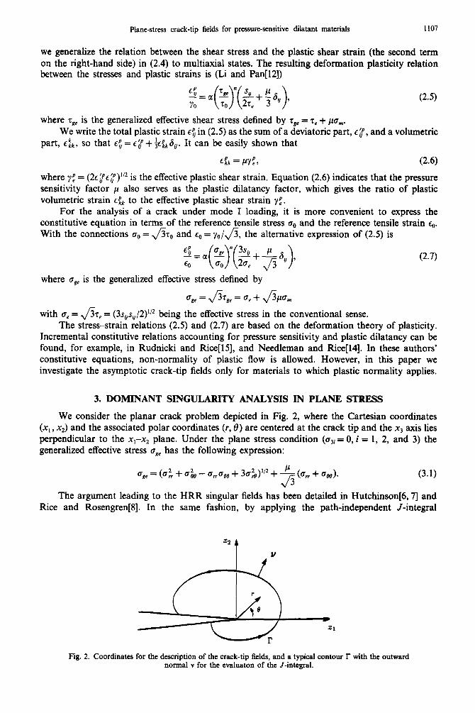
We consider the planar crack problem depicted in Fig. 2, where the Cartesian coordinates (x, , x2) and the associated polar coordinates (r, 0) are centered at the crack tip and the xj axis lies perpendicular to the x,-x, plane. Under the plane stress condition (cw = 0, i = 1, 2, and 3) the generalized effective stress age has the following expression:
The argument leading to the HRR singular fields has been detailed in Hutchinson[6,7] and Rice and Rosengren[8]. In the same fashion, by applying the path-independent J-integral
Fig. 2. Coordinates for the description of the crack-tip fields, and a typical contour r with the outward normal v for the evaluaton of the J-integral.
1108 F. Z. LI and J. PAN
introduced by Rice[ 161, the dominant asymptotic crack-tip stress, strain and displacement fields for pressure-sensitive dilatant materials can be written as
where
J= aui
-O&V, - c.r~V] -
ax, 1 ds.
(3.2)
(3.3)
In (3.3), E, = v,/,,& is the effective strain, and v, is thejth component of the outward unit normal to an arbitrary path r from the lower crack face to the upper crack face (as shown in Fig. 2). The dimensionless constant Z and the dimensionless angular functions d,, Z. and u”, depend on the strain hardening exponent n and the pressure sensitivity factor p. These angular functions are normalized by setting the maximum value of the generalized effective stress z& (as a function of 19) equal to unity. The value cge is related to 6, through the following relation:
sinB(a,,(li,-2i,)-B,(li,+P,))+~ (c?,,z-& + a”&&) de (3.5) 11 where ( ’ ) denotes differentiation with respect to 8. Note that the separable form crack-tip fields (3.2) are of the HRR type, and when p = 0, they reduce exactly to the HRR fields. In (3.2), J represents the amplitude of the asymptotic singular fields. The determination of J relies on a full analysis of a cracked body under a specific loading condition.
We follow the solution procedures used by Hutchinson[6,7], Rice and Rosengren[8], and Shih[l7, 181 to obtain the crack-tip fields for pressure-sensitive dilatant materials. The outline of these procedures is given in the following. An Airy stress function of separable form in r and 8 is introduced to satisfy the equilibrium equations. The strain components are expressed in terms of the stress function through the plastic stress-strain relation, and then are inserted into the compatibility equation to arrive at a fourth-order nonlinear ordinary differential equation with 8 as the independent variable. The traction-free conditions on the crack faces and/or the symmetry (mode I) or antisymmetry (mode II) conditions about the crack line provide the necessary boundary conditions for the differential equation. A shooting method based on a combined fourth fifth-order Runge-Kutta scheme with error and step-size control is employed to generate solutions.
4. MODE I CRACK-TIP FIELDS
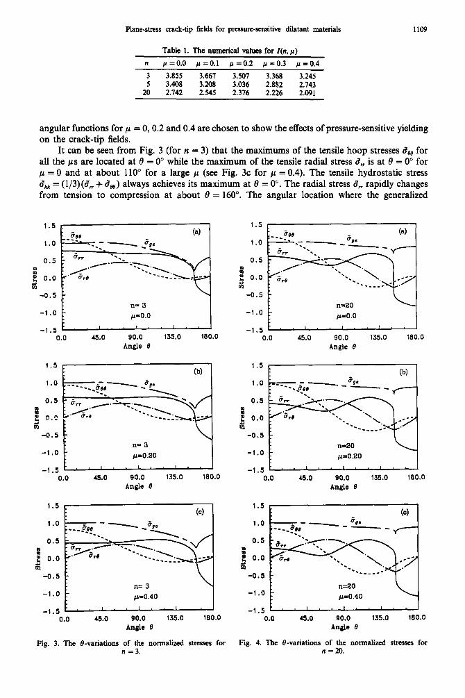
We restrict our attention to the mode I crack-tip fields. The constant Z(n, p) and the angular functions of the fields in (3.2), d,(8; n, p), Co(d; n, p) and z&(0; n, p), are obtained numerically. Our numerical results for these angular functions when p = 0 are exactly the same as the tabulated values for the plane-stress HRR fields given by Shih[l9]. The constant Z(n, p) (as listed in Table l), decreases as n or p increases. It is noted from this table that when n is fixed, the value of l/Z(n, p)“@ + ‘) in (3.2) varies with p by no more than 5%.
The &variations of the stresses g,(B; n, p) and fiBc(t9; n, p) for n = 3 (high-hardening materials) and n = 20 (low-hardening materials) are shown in Figs 3 and 4, respectively. In these figures, the
Plane-stress crack-tip fields for pressumsemsitive dilatant materials 1109
angular functions for p = 0,0.2 and 0.4 are chosen to show the effects of pressure-sensitive yielding on the crack-tip fields.
It can be seen from Fig. 3 (for n = 3) that the maximums of the tensile hoop stresses de0 for all the ps are located at 8 = 0” while the maximum of the tensile radial stress d, is at 8 = 0” for p = 0 and at about 110” for a large p (see Fig. 3c for p = 0.4). The tensile hydrostatic stress W a,, = (l/3)(5, + CM) always achieves its maximum at 8 = 0”. The radial stress d, rapidly changes from tension to compression at about 8 = 160”. The angular location where the generalized
1.5
1.0
0.5
: @ f: 0.0 m
-0.5
-1 .o
-1.5 0.0
(4
n= 3 I
45.0 90.0 135.0 180.0
Angle 9
(b) 1
n= 3
c(‘O.20
1.5
1.0
0.5
: at 0.0 5 m
-0.5
-1.0
-1.5
n= 3
0.0 45.0 90.0 135.0 180.0 Angle 0
Fig. 3. The &variations of the normalized stresses for Fig. 4. The &variations of the normalized stresses for n =3. n = 20.
Angle 0
1.5
1.0
0.5
3 * 0.0 5 C0
-0.5
-1 .o
-1.d""" ,"'I 0.0 45.0 90.0 135.0 180.0
Angle 0
1.5 (b) 1
1.0
0.5
E p) 0.0 b P
-0.5
-1.0 n=20 c(‘O.20
-1.5 1 0.0 45.0 90.0 135.0 180.0
Angle 0
1.5
1.0
0.5
I p, 0.0 s m
-0.5
-1.0
-1.5
L
(4 -- --_
0.0 90.0 135.0 180.0 Angle 0
F. Z. LI and J. PAN 1110
1.5
1.0
E: 0.5 ';li f: m 0.0
-0.5
-1.0 0.0
0-4
45.0 90.0 135.0 180.0
Angle 0
I.5 (b)
1.0
.s 0.5
5 m 0.0
-0.5
-1.0
n= 3
p=o.20
0.0 Cl.0 90.0 135.0 180.0
1.5
1.0
,s 0.5
5 VI 0.0
-0.5
-1.0
(4
n= 3
p=o.40
0.0 45.0 90.0 135.0 180.0 Andr 13
Angle 8
Fig. 5. The fbvariations of the normalized strains for n = 3.
1.5
1.0
e 0.5 ';ii 2 rJJ 0.0
-0.5
-1.0
(4
n=20
fi=o.o
1.5
1.0
E: 0.5
z
g 0.0
-0.5
-1.0
0.0 45.0 90.0 135.0 180.0
Angle 0
1.5
1.0
c 0.5 .a f m 0.0
-0.5
-1.0
n=20
p=o.40
0.0 45.0 90.0 135.0 180.0
Angle 0
Fig. 6. The &variations of the normalized strains for n = 20.
(b)
__
n=20
L(=o.20
0.0 45.0 90.0 135.0 180.0
Angle 0
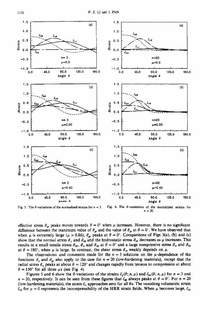
effective stress ~7s~ peaks moves towards 0 = 0” when ~1 increases. However, there is no significant difference between the maximum value of d, and the value of d, at 8 = 0”. We have observed that when p is extremely large (/A > 0.86), cBc peaks at 8 = 0”. Comparisons of Figs 3(a), (b) and (c) show that the normal stress c,, and dee and the hydrostatic stress 8kk decreases as ~1 increases. This results in a small tensile stress cige, d,, and dklr at 8 = 0” and a large compressive stress 6, and dAk at 8 = 180”, when /A is large. In contrast, the shear stress Zti weakly depends on P.
The observations and comments made for the n = 3 solutions on the p-dependence of the functions a’,, and d, also apply to the case for n = 20 (low-hardening materials), except that the radial stress d,, peaks at about 8 = 120” and changes rapidly from tension to compression at about 8 = 150” for all three ps (see Fig. 4).
Figures 5 and 6 show the e-variations of the strains &(e; n, p) and &(e; n, p) for n = 3 and n = 20, respectively. It can be seen from these figures that Z, always peaks at 8 = 0”. For n = 20 (low-hardening materials), the strain Zrr approaches zero for all 8s. The vanishing volumetric strain Zkk for Jo = 0 represents the incompressibility of the HRR strain fields. When ~1 becomes large, &
Plane-stress crack-tip fields for pressure-sensitive dilatant materials 1111
a.4
0.3
0.2
0.1
0.0
-0.1
-0.2
-0.3
-0.4
0.4 , 1
0.3
0.2
0.1
0.0
-0.f
-0.2
-0.3
Fig. 7. Contours of the generalized effective stress c~* plotted in the no~ai~ coordinates for (a) n = 3, (b) n = 20.
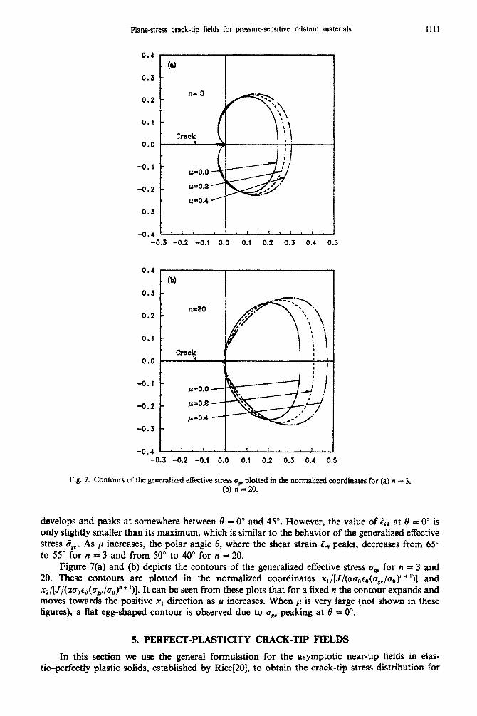
develops and peaks at somewhere between 8 = 0” and 45”. However, the value of & at 3 = 0” is only slightly smaller than its maximum, which is similar to the behavior of the generalized effective stress (78e. As ~1 increases, the polar angle 8, where the shear strain i;e peaks, decreases from 65” to 55” for n = 3 and from 50” to 40” for n = 20.
Figure 7(a) and (b) depicts the contours of the generalized effective stress uge for n = 3 and 20. These contours are plotted in the normalized coordinates xl/[J/(oloor,(a,,/ao)“+ I)] and x2/[J/(~bOt0(bge/bO)nf1)]. It can be seen from these plots that for a fixed n the contour expands and moves towards the positive x, direction as p increases. When p is very large (not shown in these figures), a flat egg-shaped contour is observed due to drre peaking at 8 = 0”.
5. PERFECT-PLASTICITY CRACK-TIP FIELDS
In this section we use the general formulation for the asymptotic near-tip fields in elas- tic-perfectly plastic solids, established by Rice[20], to obtain the crack-tip stress dist~bution for
1112 F. Z. LI and J. PAN
the pressure-sensitive materials. For a perfectly plastic material, the stress near the tip is bounded. Hence, terms of the form r(&r,/&) in the equilibrium equations must vanish as r-+0. Therefore, the equilibrium equations (in the polar coordinate system) reduce to two ordinary differential equations[20]:
da, a,, - see + - = 0,
dt’ (5.1)
20 -l-*=0 f+ dt7 . (5.2)
The yield condition for the pressure-sensitive material is written as
Combining the differential form of the yield condition and the asymptotic form of the equilibrium equations, Rice[ZO] derived the governing equation for plastic sectors near the tip:
(5.4)
where prr = Jf/aa, can be interpreted as the rr component of the outward normal to the yield surface in the stress space.
Equation (5.4) leads to the following forms of simple solutions near the tip:
(1) Constant stress sectors
Within a constant stress sector, the Cartesian stress components a,, , a22 and a,2 are independent of 8, i.e.
al, = constant,
a22 = constant, (5.5)
al2 = constant,
where the constants are to be determined from the yield condition and the relevant boundary conditions.
(2) Centered fan sectors
Within a centered fan sector,
PII = 0. (5.6)
Equation (5.6) indicates that the radial lines correspond to one of the two families of characteristics. When normality plastic flow is assumed, the extensional (or compressive) strain component along the radial lines vanishes.
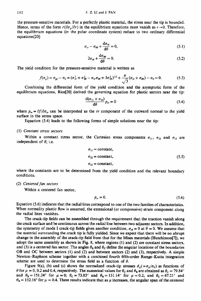
The crack-tip fields can be assembled through the requirement that the traction vanish along the crack surface and be continuous across the radial line between two adjacent sectors. In addition, the symmetry of mode I crack-tip fields gives another condition, arg = 0 at 0 = 0. We assume that the material surrounding the crack tip is fully yielded. Since we expect that there will be no abrupt change in the assembly of the crack-tip field from that for the Mises materials (Hutchinson[fl), we adopt the same assembly as shown in Fig. 8, where regions (1) and (2) are constant stress sectors, and (3) is a centered fan sector. .The angles &, and 6, define the angular locations of the boundaries OB and OC between sectors (1) and (2) and between sectors (2) and (3), respectively. A simple Newton-Raphson scheme together with a combined fourth fifth-order Rung+Kutta integration scheme are used to determine the stress field as a function of 8.
Figure 9(a), (b) and (c) shows the normalized crack-tip stresses d,(=a,/a,) as functions of 8 for p = 0,0.2 and 0.4, respectively. The numerical values for 0, and (Jr, are obtained as f3c = 79.84” and &, = 151.24” for Jo =O; &= 73.03” and &,= 151.14” for fi =0.2; and &=67.21” and Be = 152.16” for p = 0.4. These results indicate that as p increases, the angular span of the centered
Plane-stress crack-tip fields for pressure-sensitive dilatant materials 1113
Fig. 8. The assembly of crack-tip fields for perfectly-plastic pressure-sensitive materials.
1.5
1.0
0.5
.z o 0.0 5 m
-0.5
-1.0
-1.5
1.5
1.0
0.5
1 p) 0.0 ii m
-0.5
-1.0
-1.5
(b)
i.
0.0 45.0 90.0 135.0 180.0
----.._tee (4
-. - urr l .
A.-. *. w .., .
s’re l \ --____- p=o.o
1.5
1.0
0.5
s o) f; 0.0 m
-0.5
-1 .o
-1.5
r--._ . pee
0.0
90.0 135.0 180.0
Angle 0 0.0 45.0
Angle 8
45.0 90.0 135.0 180.0
Angle 0
Fig. 9. The stress distributions of dB( = a,/~,,) and CT~~( = ~,,/a~) for perfectly-plastic pressure-sensitive materials.
F. 2. LI and J. PAN
1.5 (4
n= 3
‘Y.-. *m -.-
0.0 - 0.0 0.2 0.4 0.6 0.8
w
1.5 (b) 1
c I
: n=20
m 1.0 . . .._qee S
v --._
$ --..
: -... -... .I 7
z Oa5 z
i;
“C . .
‘5. OnI ..A.
0.0 - 0.0 0.2 0.4 0.6 0.6
P
1.5 (cl
z Perfectly Plastic
5 m 1.0 . ..~M
--._ ‘CI
--._
$ 0, -.._
-... -...
._
a
E Oe5 2 ‘-;- ‘z=..
-*-
0.0 - 0.0 0.2 Q,4 0.6 0.8
P
Fig. 10. The p-dependence of the normalized stresses at 0 = 0” (the stresses are normalized by oo[J/(ao,c,r)]‘““+‘) for n = 3 and 10, and by q, for perfectly-plastic materials).
fan sector ahead of the crack tip decreases; however, the angular location of the boundary between the two constant stress sectors changes only slightly. Note that the solutions have radial stress discontinuity along the boundary OB between the two constant stress sectors. A comparison of Fig. 4 (for the n = 20 solutions) and Fig. 9 shows that our perfectly plastic solutions indeed correspond to the low-hardening limit of the power-law solutions.
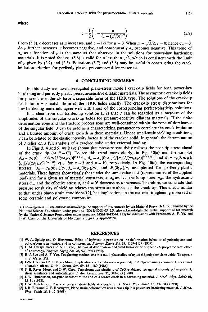
The stress state ahead of the crack tip at 8 = 0” seems to have an important implication on crack initiation. As shown in Fig. 9, as ,u increases, the hoop stress c88 and the radial stress c,, at 8 = 0” decreases. This indicates that the pressure sensitivity of materials relieves the hydrostatic stress ahead of the crack tip. This trend is in agreement with that for power-law hardening materials as discussed earlier and _ that of the crack-tip fields under plane strain conditions[ 121. The closed-form solution for the stresses ahead of the tip (at t9 = O”) can be derived easily as
(5.7)
Plane-stress crack-tip fields for pressure-sensitive dilatant materials 1115
where
From (5.8), c decreases as ~1 increases, and c = l/2 for p = 0. When p = a/2, c = 0; hence o,, = 0. As p further increases, c becomes negative, and consequently u,~ becomes negative. This trend of 0, as a function of ~1 is the same as that observed in the solutions for power-law hardening materials. It is noted that eq. (5.8) is valid for ,u less than fi, which is consistent with the limit of p given by (2.2) and (2.3). Equations (5.7) and (5.8) may be useful in constructing the crack initiation criterion for perfectly plastic pressure-sensitive materials.
6. CONCLUDING REMARKS
In this study we have investigated plane-stress mode I crack-tip fields for both power-law hardening and perfectly plastic pressure-sensitive dilatant materials. The asymptotic crack-tip fields for power-law materials have a separable form of the HRR type. The solutions of the crack-tip fields for p = 0 match those of the HRR fields exactly. The crack-tip stress distributions for low-hardening materials agree well with those of the corresponding perfect-plasticity solutions.
It is clear from our hardening solution (3.2) that J can be regarded as a measure of the amplitudes of the singular crack-tip fields for pressure-sensitive dilatant materials. If the finite deformation zone and the fracture process zone are well-contained within the zone of dominance of the singular field, J can be used as a characterizing parameter to correlate the crack initiation and a limited amount of crack growth in these materials. Under small-scale yielding conditions, J can be related to the elastic intensity factor K of the cracked solid. In general, the determination of J relies on a full analysis of a cracked solid under external loading.
In Figs 3, 4 and 9, we have shown that pressure sensitivity relieves the near-tip stress ahead of the crack tip (at 8 = 0”). To see this trend more clearly, in Fig. 10(a) and (b) we plot des = ~~(0; n, ~)/{60[J/(clbg~~)]“(n + I)>, d, = a,(O; n, ~)/{bOIJ/(a~g~Or)]“(n + I)}, and ee = a,(O; n, P)/
bdJl&wo~N ‘/(“+‘)} vs p for n = 3 and n = 10, respectively. In Fig. 10(c), the corresponding stresses, bee = a&O; ~)/a~, d, = a,(O; p)/oO, and c?~ (0; ~)/a,, are plotted for perfectly-plastic materials. These figures show clearly that under the same value of J (representative of the applied load) and for a given set of material constants, ~1, crO and co, the hoop stress egg, the hydrostatic stress cm,, and the effective stress 6, at 8 = 0” decrease as p increases. Therefore, we conclude that pressure sensitivity of yielding relaxes the stress state ahead of the crack tip. This effect, similar to that under plane-strain conditions[l2], has implications in the material toughening observed in some ceramic and polymeric composites.
Acknowledgements-The authors acknowledge the support of this research by the Material Research Group funded by the National Science Foundation under grant no. DMR-8708405. J.P. also acknowledges the partial support of his research by the National Science Foundation under grant no. MSM-8613544. Helpful discussions with Professors A. F. Yee and I.-W. Chen of The University of Michigan are greatly appreciated.
111
PI
[31
[41
[51
161
t;;
REFERENCES
W. A. Spitzig and 0. Richmond, Effect of hydrostatic pressure on the deformation behavior of polyethylene and polycarbonate in tension and in compression. Polymer Engng Sci. 19, 1129-l 139 (1979). L. M. Carapellucci and A. F. Yee, The biaxial deformation and yield behavior of bisphenol-A polycarbonate: effect of anisotropy. Polymer Engng Sci. 26, 920-930 (1986). H.-J. Sue and A. F. Yee, Toughening mechanisms in a multi-phase alloy of nylon 6,6/polyphenylene oxide. To appear in J. Mater. Sci. I.-W. Chen and P. E. Reyes Morel, Implications of transformation plasticity in ZrO,containing ceramics: I, shear and dilatation effects. J. Am. Ceram. Sot. 69, 181-189 (1986). P. E. Reyes Morel and I.-W. Chen, Transformation plasticity of CeG,-stabilized tetragonal zirconia polycrystals: I, stress assistance and autocatalysis. J. Am. Cerwn. Sot. 71, 343-353 (1988). J. W. Hutchinson, Singular behavior at the end of a tensile crack in a hardening material. J. Mech. Whys. Solids 16, 13-31 (1968). J. W. Hutchinson, Plastic stress and strain fields at a crack tip. J. Mech. Phys. Solids 16, 337-347 (1968). J. R. Rice and G. F. Rosengren, Plane strain deformation near a crack tip in a power law hardening material. J. Mech. Phys. Solids 16, l-12 (1968).
EFM 3516-L
1116 F. Z. LI and J. PAN
[9] J. Pan and C. F. Shih, Plane-strain crack-tip fields for power-law hardening orthotropic materials. Mech. Mater. 5, 299316 (1986).
[lo] J. Pan and C. F. Shih, Plane-stress crack-tip fields for power-law hardening orthotropic materials. Znr. J. Fracture 37, 171-195 (1988).
[l I] J. W. Hutchinson, Constitutive behavior and crack tip fields for materials undergoing creep-constrained grain boundary cavitation. Acra Metali. 31, 10791088 (1983).
[12] F. Z. Li and J. Pan, Plane-strain crack-tip stress and strain fields for pressure-sensitive dilatant materials. To appear in J. Appl. Mech.
[13] D. C. Drucker, Plasticity theory, strength-differential (SD) phenomenon, and volume expansion in metals and plastics. Metall. Trans. 4, 667-673 (1973).
[14] A. Needleman and J. R. Rice, Limits to ductility set by plastic flow localization, in Mechanics of Sheet Metal Forming (Edited by Donald P. Koistinen and Neng-Ming Wang). Plenum, New York (1978).
[15] J. W. Rudnicki and J. R. Rice, Conditions for the localization of deformation in pressure-sensitive dilatant materials. J. Mech. Phys. Solids 23, 371-394 (1975).
[16] J. R. Rice, A path independent integral and the approximate analysis of strain concentration by notches and cracks. J. appl. Mech. 35, 379-386 (1968).
[17] C. F. Shih, Elastic-plastic analysis of combined mode crack problems. Ph.D. Thesis, Harvard University, Cambridge, Massachussetts (1973).
[ 181 C. F. Shih, Small-scale yielding analysis of mixed mode plane-strain crack problems, in Fracture Analysis, ASTM STP 560, 187-210 (1974).
[19] C. F. Shih, Tables of Hutchinson-Rice-Rosengren singular field quantities. Report MRL E-147, Materials Research Laboratory, Brown University, Providence, Rhode Island (1983).
[20] J. R. Rice, Elastic-plastic crack growth, in Mechanics of Soliris: The R. Hill 60th Anniversary Volume (Edited by H. G. Hopkins and M. J. Sewell), pp. 539-562. Pergamon Press, Oxford (1982).


![Fatigue Crack Growth Under Constant and Variable Amplitude ... · crack closure effects, crack tip blunting, strain hardening and residual stresses at the crack tip [8]. In this paper,](https://static.documents.pub/doc/80x56/5e57a3e927dba642fd37d97c/fatigue-crack-growth-under-constant-and-variable-amplitude-crack-closure-effects.jpg)


