5.2 Site Database ................................................................................................................... 19 5.2.1 Site Database Operations .......................................................................................... 19
5.2.1.1 Setting Active Sites............................................................................................... 20 5.2.1.2 Editing the Site List .............................................................................................. 20 5.2.1.3 Using the Global Editor ........................................................................................ 20 5.2.1.4 Exporting information........................................................................................... 20
7.3.2.1 Files - Storing Data ............................................................................................... 26 7.3.2.2 Traffic ................................................................................................................... 27 7.3.2.3 Deciding Which Sites to Include in an Analysis .................................................. 27 7.3.2.4 Deciding on the Number of Simulations .............................................................. 27 7.3.2.5 Setting CDMA Parameters ................................................................................... 27
7.3.2.5.1 System Settings............................................................................................... 27 7.3.2.5.2 Mobile Settings ............................................................................................... 28 7.3.2.5.3 Carrier Settings ............................................................................................... 29 7.3.2.5.4 Base Station Settings ...................................................................................... 30 7.3.2.5.5 FER to Eb/No Mapping Screen ...................................................................... 31 7.3.2.5.6 Clutter Factors................................................................................................. 31 7.3.2.5.7 Memory Usage Settings.................................................................................. 31
7.3.2.8.1 Creating a System Report ............................................................................... 32 7.3.2.8.2 Creating a Served User Status Report............................................................. 33 7.3.2.8.3 Creating a Blocking Status Report.................................................................. 33 7.3.2.8.4 Creating a Reverse Performance Report......................................................... 33 7.3.2.8.5 Creating a Forward Performance Report ........................................................ 33
8.2 Survey Prediction Tool ................................................................................................... 36 8.2.1 Assigning Surveys to Site:Sectors ............................................................................ 37 8.2.2 Survey Header Summary .......................................................................................... 37 8.2.3 Using the Create Survey Predictions Window.......................................................... 37
8.3 Test Mobile ...................................................................................................................... 37 8.3.1 Test Mobile Data Files.............................................................................................. 38
8.3.2 Test Mobile Window ................................................................................................ 39 8.3.2.1 Signalling Analysis ............................................................................................... 40 8.3.2.2 XY Graphs ............................................................................................................ 40 8.3.2.3 Test Mobile Information ....................................................................................... 40 8.3.2.4 Statistics ................................................................................................................ 41
9 PREDICTION MECHANISM + TIME + ACCURACY .............................................41
9.1 Model Database............................................................................................................... 41
9.2 Model Editor ................................................................................................................... 41 9.2.1 Model Editor Window .............................................................................................. 41
9.2.1.1 File Menu.............................................................................................................. 42 9.2.1.2 Getting Information about an Existing Model ...................................................... 42
Planet DMS 3.1 Evaluation Report (Focused on CDMA)
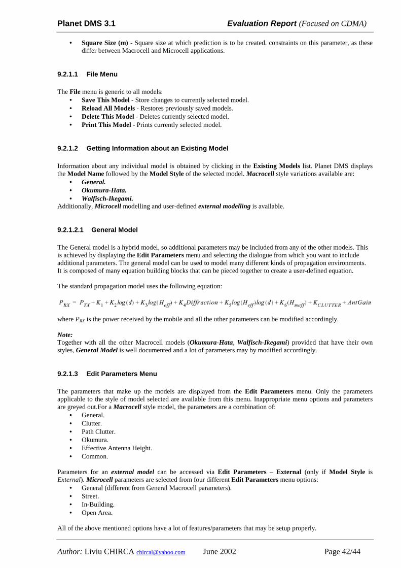
9.2.1.2.1 General Model ................................................................................................ 42 9.2.1.3 Edit Parameters Menu........................................................................................... 42 9.2.1.4 Ray Tracing Model ............................................................................................... 43
9.3 Automatic Model Tuner................................................................................................. 43
10 RELATED DOCUMENTATION EVALUATION..................................................43
11 ANALYSIS + SITES DATABASE EXPORT OPTIONS ���� TO MAPINFO..........43
0 Summary of this report The purpose of this report is intended to analyze and to present (summary) the features of Planet tool made by Marconi - MSI (see http://wnp.marconi.com/planet/index.shtml Planet’s web page) as RF Planning toll. This report has been focused on the CDMA features and especially on the following 12 chapters: 1. Installation + Preliminary Settings How to install, what resources are needed, directory settings, how to work with (interface), Operating System Multiple users operation / distributed operation / information organization mode 2. MAPS (Elevation / Clutter / Vectors) Data importing Format Coordination / Projection Settings Clutter / Elevation / Vectors Displaying Display part of maps (regions) and times required 3. Spectrum definition 4. Antenna pattern definition / editing How to import/edit antenna pattern from an *.xls or other used format 5. Sites Database Format Importing Parameters to be set Parameters to be set: how to do, especially for CDMA systems Global editing of sites Splitted sectors configuration definition 6. Traffic spreading and analysis How to define specific traffic areas (polygon definition, etc) Spreading analysis 7. Analysis – CDMA – Spread Spectrum What kind of analysis / how many features / metrics to be analysed How accurate could be analysis (confidence) 3G1X features CDMA metrics Extension Range Feature 8. Measurement Data Integration For analogue NMT system – how to do File format to be accepted for import 9. Prediction mechanism + time + accuracy If possible, comparison of results / plots Propagation models definition and integration of new models 10. Related Documentation evaluation 11. Analysis + Sites Database export options ���� to MapInfo 12. Conclusions
1 Installation + Preliminary Settings • How to install, what resources are needed, directory settings, how to work with (interface), Operating System • Multiple users operation / distributed operation / information organization mode
1.1 Hardware Recommendations This section describes the recommendations regarding the hardware requirements for implementing Planet DMS. It covers the general requirements for guidance only, please contact MSI for further clarification. Oracle Server Requirements (2 to 8 users) Sun Ultra 10S (Server) 440 MHz processor 256 Ram GB 4 GB internal HDD SCSI Controller Backup device DDS-3 or DLT 4 external HDD (4 x 4GB) (minimum) Same Server Requirements Sun Ultra 10 360 MHz processor 256 MB RAM (512 MB preferred) 20" Colour Monitor SCSI Interface Card Client Hardware Requirements Sun Ultra 60 Model 1300 256 MB RAM 8.4 GB Hard Disk Drive Creator 24-bit Colour Accelerated Graphics Card Solaris 2.6 Operating System 20" Colour Monitor Version under PC (Windows) At the end of July 2002 an official release of Planet under PC (Windows) will be available. There are already available some details regarding “Sharing data between Planet Unix and Windows”. For further details please contact Mr. Jens Frenkel ([email protected]). 1.2 Planet DMS User Documentation There are two Reference Guides that you may need when you are using Planet DMS: • User Reference Guide, which explains how to use the Planet DMS features. • Technical Reference Guide, which explains the more technical details, such as Planet DMS’s Oracle table
contents, file formats and propagation models. These Guides document all the functions that are available in Planet DMS. However, the functions that are available to you depend on the package(s) that your organisation has purchased, so a guide may include information about a function that you cannot use. • There is also a Planet DMS Installation Guide, which explains what must be done to install Planet DMS and to
make it available to users.
1.3 Planet DMS Packages The Planet DMS tools and functions are grouped into packages. Access to these packages is controlled by the Planet DMS license manager software. MSI believes that grouping Planet DMS into functional packages offers better value to our customers, because it allows them to buy only the functions that are needed for their business at advantageous prices.
There are six Planet DMS packages: • Planet DMS Data Management. • Planet DMS Technology. • Planet DMS Designer+. • Planet DMS Coverage. • Planet DMS Capacity. • Planet DMS Optimize.
A tailored version of each package is available for each of the standard radio technologies (GSM, CDMA, WCDMA, TDMA, WLL, IS-136, IS-54 and Microwave). A number of optional modules can be purchased and used in conjunction with the Planet DMS Technology, Designer+, Coverage, Capacity, Optimise packages. These modules include the Microwave tool.
1.4 Planet DMS User Interface This chapter provides information on:
• The main Planet DMS window. • Using the mouse. • Moving and Resizing windows. • Moving Around. • List Boxes. • Planet DMS Terminator.
The Terminator program is separate from Planet DMS. It allows you to stop time consuming Planet DMS processes before they finish, by sending a signal to Planet DMS which Planet DMS recognises as a STOP! instruction. Terminator is particularly useful if you make a mistake during creation of a large coverage array or when attempting to display heights over a large area using a small contour interval.
1.5 Running Planet DMS This chapter provides information on:
• Before starting Planet DMS. • Planet DMS Definition files. • Planet DMS Login. • Planet DMS Workspaces. • Selecting a Workspace. • Work with workspaces:
� Open. � Closed. � Copy. � Compair. � Merge.
The latest versions of Planet are referred to as Planet DMS because of the underlying Oracle Database system on which it was built. The change from a system based on standard, flat, files to a Database Management System of Tables has a number of advantages both commercial and technical. Commercially the Relational Database approach is becoming an industry standard which allows greater manipulation of data both inside and outside the framework of Planet. Technically it allows greater security in that access is restricted and Configuration Management is easy to implement. The DMS versions of Planet allows users to work on their own “workspace” or a group of users to work on a particular “workspace”. All that is required is to set up an initial workspace, the root, which could then be copied and worked on. This workspace can then be compared with another workspace and any differences merged to produce a final overall plan. Security is implemented by the fact that a user has first to “log on” and select the “workspace” within which they wish to work.
Planet DMS 3.1 Evaluation Report (Focused on CDMA)
1.5.1 Planet DMS Access Controls To start Planet DMS you have to have:
1. A valid Planet DMS user ID. 2. A Planet DMS login password. 3. Proper access rights to the Oracle database.
There are described what happens if Oracle fails and which are recovery options (please see Planet DMS Installation & Administration Guide for information about using the dms_imex utility). 1.5.2 Planet DMS Definition File The Planet DMS definition file, planet_def, contains default settings for your Planet DMS session, including default specifications for the files used in contour intervals, file and directory names for data, system type, and so on. Changing/Editing the Definition File: The following is a list of parameters in the planet_def file that are editable:
• systype - tells Planet DMS the type of system it will be used to plan and should, therefore, be configured for. (GSM, CDMA, WLL, etc)
• lat_long.database - denotes whether the Site database is stored in grid coordinates or geographical (latitude-longitude) coordinates.
• layer.maxPredMem - specifies the amount of memory that is available for interference calculations. • dqt.databaseType - only valid if you will be using the Database Query Tool to query the database. • dqt.databaseName - only valid if you will be using the Database Query Tool to query the database.
It can be used an ASCII text editor, such as vi, to edit the definition file parameters. If you edit the definition file that is currently in use by Planet DMS, you must close and re-start Planet DMS to activate the changes. 1.5.3 Starting Planet DMS When the Planet DMS Login window appears, the 4 fields within it may already be filled or they may be blank. You must complete all the fields before you can access and use Planet DMS data. The 4 fields that have to be completed are: 1. Oracle User - Your Oracle user ID - Your user ID must be set up by the Planet DMS/Oracle. (Can be set up as an environment variable in your login script, or may be typed in, as required.) 2. Oracle Password - Your password to the Oracle database (Your password must be set up by the Planet DMS/Oracle administrator before you start to use Planet DMS. Usually, entered each time you login to Planet DMS. Can be set up as an environment variable, but this is not recommended as it can lead to a lack of security for the database.) 3. Oracle Service Name - Installationspecific:ask your Planet DMS or Oracle administrator what you must enter. (Must be set up by the Planet DMS/Oracle administrator before you start using Planet DMS. Cannot be edited.) 4. Initial Workspace Name of the workspace specified in your Planet DMS definition file . (The value is defaulted from a entry in your Planet_def file, which must be set up by your Planet DMS administrator.) 1.5.4 Planet DMS Workspaces A workspace provides a view of the network design data in the Planet DMS databases. When Planet DMS is first installed, a single view (workspace) is created - the root workspace. Starting with this single workspace, one or more copies can be made and edited. Each of these copies may also be copied and edited. This process creates a hierarchy of different views derived from, but different to, the original network data set. Because a single workspace may be copied several times, and each new workspace modified in different ways, workspaces simplify the task of making and comparing different network designs for the same area. In addition, a number of engineers may work on designs for the same area at the same time without inadvertently interacting with each other’s work. This is because the data for each workspace is distinguished in the Planet DMS database tables. When the design in a workspace has been edited and optimized, its workspace can be compared with a related workspace, and, if required, one design can be merged into another. In summary, Planet DMS allows you to:
1) Share a single design with many other users without impacting on each other’s work. 2) Create multiple versions of a design, with each version differing in details.
Planet DMS 3.1 Evaluation Report (Focused on CDMA)
3) Compare two designs to determine which aspects are shared and which are unique to one design. 4) Create a consolidated design for an area by merging some or all the details from two existing designs.
Planet DMS allows multiple users to share workspaces. Therefore, you may not be the only person who works with any given workspace, even if you are the owner. In some situations, customers may want to:
1) Share only some workspaces and have their own workspace hierarchies. 2) Transfer workspace data from one office to another and have no formal connection between offices.
DMS workspace import caters for these possibilities by providing: 1) The ability to create a workspace by copying data from a workspace at another office. The newly created
workspace will have its own name and will not be automatically merged with its source workspace at the source office.
2) The ability to continue to allow local working when links to other offices are down.
1.5.4.1 Workspace Manager The Workspace Manager is a tool for managing workspaces. For descriptions of specific workspace management function, there are:
1) The Root Workspace. 2) Selecting a Workspace. 3) Creating Workspaces. 4) Copying a Workspace. 5) Importing a Workspace. 6) Opening a Workspace. 7) Closing a Workspace. 8) Getting Information about a Workspace. 9) Comparing Workspaces. 10) Merging Workspaces. 11) Renaming Workspaces. 12) Workspace Permissions.
The Planet DMS installation process will always create a root workspace. The root workspace is always created empty - without any Planet DMS data assigned to it. We recommend that no data is loaded into the workspace and that nobody works in it. This will ensure that a clean workspace is always available for use as a basis for designs that do not use existing data. Detail Reports – It can obtain detailed information (reports) about an entry in any of the lists (following a comparing workspaces process) by clicking once on the selected entry, then clicking on the Generate Report button. 1.5.5 DMS Input/Output Tool DMS/IO allows Planet workspaces to be imported and exported from a set of files. The utility is complementary to the dms_imex utility, and is intended to be used for moving datasets between databases. Note: dms_imex utility has been already used with success to import site data base into one workspace using an external macro (local build) to provide formatted data as required (see Planet DMS Installation & Administration Guide for details about dms_imex utility and chapter 5 from this report)
2 MAPS (Elevation / Clutter / Vectors) Data importing Format Coordination / Projection Settings Clutter / Elevation / Vectors Displaying Display part of maps (regions) and times required
Planet DMS 3.1 Evaluation Report (Focused on CDMA)
2.1 Mapping Data Files This chapter discusses the format for the files that store: Mapping data, including heights, morphology (land usage or clutter), vector data and text data, height and clutter data. The chapter also gives details on the stipple file that can be used when displaying coverage arrays, and background information about scanned maps. Mapping data is stored in a grid system even if the viewed co-ordinates are in latitude - longitude. Mapping, height and clutter data are stored in binary format files. The country is split into small manageable sections, typically 20km or 40km square. The resolution of the data is often a compromise between detail required, amount of file space available on disk and the speed of predicting coverage for cell sites. In general, the higher the data resolution, the more disk space is needed and the time for each prediction is increased. A typical element size is 50, 100, or 200 metres although other resolutions can be used. If only data for, say, 50m is available, then Planet DMS can only display to a resolution of 50m. If other resolutions are needed, they must be generated elsewhere. 2.1.1 Height Data The country is split up into regions of perhaps 20km by 20km. The coordinates defining the edges of the area are held in an index file. To cater for more than one area size, the index file allows multiple entries for each area of the country and Planet DMS will only load the data file if the area size in the index file matches the area size currently being used in Planet DMS. Height data for the area within the square is held in binary array format, with each word of the array being 2 bytes in size. The most significant byte is stored first. The height in each element is the height of the ground above mean sea level, in meters. Height Data Storage When you edit height details in the height editor, Planet DMS stores the edits in a subdirectory called user in the height data directory. All height files are held in this one directory. The directory also contains an ASCII text file named index, which holds positional information about each of the height files. Use of the Index File When height data is being calculated, the index file is scanned first to determine which height files Planet DMS needs to load. The coordinates referred to in the index file define the edges of the square. The coordinates and square size are expressed in metres. Eastmin, Eastmax, Northmin and Northmax define the position of the square. Writing Data to the Files: Access Permissions Planet DMS can only write data to the directory if you have write-permissions for the following items:
• The user directory in the height directory. • The index file in the user directory.
Projection File An optional file, projection, may be included in the heights directory. This file is used when coordinates in Planet DMS are required in latitude/longitude. It is an ASCII text file with up to four lines of information.
1. Spheroid, 2. Zone, 3. Projection, 4. Central Meridian.
2.1.2 Clutter Data When you edit clutter details in the clutter editor, Planet DMS stores the edits in a subdirectory called user in the clutter data directory. Planet DMS creates this directory and an index file, if they do not already exist. Standard clutter data is stored in the same format as height data: Menu File The menu file defines the feature codes for each type of clutter. It consists of as many lines of the following format as there are clutter codes in the clutter data files:
Planet DMS 3.1 Evaluation Report (Focused on CDMA)
1. clutter-code, - Integer representing a clutter type. All clutter values must be 1 or greater (not 0). 2. feature-name, - Name associated with the clutter-code. It may contain spaces.
Clutter Index File This index file is scanned first to determine which clutter files Planet DMS needs to load. It consists of the following fields:
Eastmin, Eastmax, Northmin, Northmax and Square size. The coordinates are in units of meters, the square size is also in meters. Writing Data to the Files: Access Permissions Planet DMS can only write data if you have write-permissions for the following items:
1. The menu file in the clutter directory. 2. The user directory in the clutter directory. 3. The index file in the user directory.
2.1.3 Vector Data Vector data contains features such as coastlines, roads, railways, etc. Each of these features must be stored in a separate vector file. Four types of file are used to represent the properties defined in the model. These are as follows:
1) The menu file: lists the vector types stored in the database. 2) The index file: lists the vector files in the directory. 3) The vector file: stores the easting and northing coordinates of the vector paths. 4) The attribute file: stores the height and description properties of vector paths. This file is optional.
Main Vector and User Vector Directories Vector data is stored in either one or two directories: 1) A main vector directory, whose location is user-defined. This directory is used for storing externally generated
mapping data. The directory contains a Menu file, an Index file, a number of Vector files and optionally, a number of Attribute files.
2) A user vector directory, whose location is user-defined. This directory is used for storing any user-generated mapping data that is created using the Planet DMS Vector Editor. The directory contains an Index file, a number of Vector files and optionally, a number of Attribute files.
Menu File This is an ASCII text file, named menu. There is only one menu file in the Planet DMS vector database. It is located in the main vector directory. It lists the vector types found in both the main and user vector directories. There is one entry in the Menu file for each vector type present in the database. Index File This is an ASCII text file, named index. It lists the vector files in a directory and associates each vector file with one vector type and optionally, one attribute file. There is one index file in each Planet DMS vector directory. There is one line in the index file for each vector file in that directory. Vector File This file is used to store vector path data. There are two different formats for vector files: ASCII and binary. The name of a binary format vector file must end with the suffix .bin. The name of an ASCII format vector file must not end with the suffix .bin. A vector file will be assumed to be in ASCII format if it does not have the .bin suffix. The advantages of storing vectors as binary files are that they occupy less disk space and load more quickly into Planet DMS than the text equivalent. Attribute File This file is used to store attribute information about the vector paths in a given vector file. Attribute files are optional. Zero or one attribute files may exist for one vector file. The fields in the attribute record are separated by space characters. 2.1.4 Text Data Text data is used to supply a tag for a map reference. It is simply a line of ASCII text followed by the easting and northing of that map object. Each file should be split-up into regions and each region stored in a different file. Index File As with the vector and height data, a file called index stores the position of each text file. If there is no menu file, the last field in the index file is omitted.
Planet DMS 3.1 Evaluation Report (Focused on CDMA)
Menu File There is an optional menu file which contains the text features in the same way as the vector menu file. For example:
0 Towns 1 Cities 2 Provinces
2.1.5 Scanned Maps You can obtain scanned maps for use with Planet DMS from a variety of sources: Ordnance Survey maps, aerial photographs, or satellite pictures, for example. Planet supports both standard and compressed TIFF files for scan maps. Both LZW and UNIX compression are supported, as well as Apple Macintosh PackBits compression. Standard TIFF and compressed TIFF format files can exist and be displayed side by side. Scan the information and save it as a TIFF file with the following characteristics:
1. It must be in version 6.0 format or later. 2. Compressed or uncompressed format. 3. There must only be one image in the .tif file.
If you create files from the same map information, but save each file at a different resolution, you can store the files and Planet DMS automatically switches between the different resolution files as you zoom in on the display. This is highly recommended because it speeds up the display of scanned maps. You must also create an index file for each set of multi-resolution files. This has the same format as the height data file:
2.2 Display Menu This chapter explains the function of those items controled by Display menu. The Display menu controls information displayed on the main window. The Display menu is used for the following functions: Redraw, Map, Hexagons, Coverage, Carriers, Zoom, Profile, Search, 3D Plot, Edit List, Key, Mouse info 2.2.1 Map The Display - Map option opens a window that displays geographical data, such as mapping and morphology information, including:
1. Text data Textual information such as city names. 2. Mapping data Morphology, terrain heights, scanned maps and vectors. 3. Site locations Physical locations of cell sites.
The Map menu contains seven options, as shown below. You select the desired option with the mouse Menu button: Cellids, Grid, Text, Clutter, Vectors, Heights, Scan Map. Note. When you display Heights you may use the Terminator button to interrupt the display load if it is taking longer than necessary. 2.2.2 Hexagons The geographical area for a radio system is split into a number of smaller areas called cells. A radio base station covers one or more cells. The idealized situation is a honeycomb of hexagonal cells. In reality, the concept of idealized hexagons could never be achieved because of the irregular characteristics of radiowave propagation. Radio base stations not only provide coverage for their own cells but also cover parts of adjacent cells. The facility to work on a basic initial design using hexagons of differing sizes is often very useful. (Detailed options are available) 2.2.3 Coverage The Coverage display shows signal coverage and interference information. (Note: A prediction for the site must exist before a display can be produced for it. - Detailed options are available) 2.2.4 Zoom The Zoom menu lets you increase and decrease the size of the geographical area displayed on the main screen. The Zoom menu is split into two columns:
Planet DMS 3.1 Evaluation Report (Focused on CDMA)
A) Magnafication Factor The left hand column of the Zoom window lists magnification factors. Selecting a value in this column will cause Planet DMS to display a larger area of terrain. For example, if the existing map displays an area of which each side is 50km, zooming out by x 3 will display a map with sides of 150km each. Home returns to the default screen, and Last returns to the previously-displayed screen. B) Viewing Area The righthand column lists pre-set values defining the area of map coverage that will be displayed. For example, selecting 20km will display a map area 20 km by 20 km; that is, an area of 400 square kms. The last item in the column – Region – allows you to zoom to a region and display region details in another window. 2.2.5 Profile Profile lets you view a cross-section of the terrain map. (Key... displays a legend to the profile display options) The profile path is determined by clicking the start location and dragging the mouse to the end location and clicking again when the desired profile is obtained. A line is drawn indicating the profile path as the mouse is moved. (A lot of settings may be done for modifying Fresnel Zone Factors, Profile setup window, K factor) 2.2.6 Search The Search facility enables the following information to be displayed in the center of the main window, marked by a cross:
• A selected base station. • A coordinate. • A text label. • The centre of a heights database. • The centre of a clutter database. • A position dictated by the mouse pointer. • A defined project centre.
The zoom facility can also be accessed via Search. 2.2.7 3D Plot The 3D Plot function plots the entire displayed terrain, viewed from south to north. This feature is useful for visualizing large areas of terrain. 2.2.8 Edit List Display -✎ Edit List pops up a window listing the items displayed in the main Planet DMS window. You can: 1. Remove all displayed items from the screen. 2. Remove selected items from the screen. 3. Move displayed items to be moved into the background so that they do not have to be drawn again every time a
Display -✎ Redraw is performed. Up/down arrows Planet DMS displays individual layers starting with the layer at the top of the Display List Editor. As a result, subsequent layers will overdraw the preceding layers. The arrows enable display layers to move up and down the priority list. Layers sent to the background are raised in the layer hierarchy by the action of sending them to the background. Moving layers in the background down the list will cause the layers. 2.2.9 Key The Key window lists all of the items displayed on the main Planet DMS screen along, with a legend stating the colors, line styles and values represented. The key is appended to plots produced by Planet DMS. You can use the scroll bar on the right of the key to scroll through the displayed values if the key list extends past the end of the window. 2.2.10 Mouse info The Mouse Info window provides an additional method for displaying the information which appears at the bottom of the main Planet DMS window. While the Mouse Info window is open, identical information is displayed both in this window and at the bottom of the main window. This is useful if the bottom of the main Planet DMS window is obscured.
Planet DMS 3.1 Evaluation Report (Focused on CDMA)
2.3 Settings Menu This chapter explains the function of those items controlled by Settings menu. The Settings window is accessed from the main Planet DMS window. It lets you define the settings for the current Planet DMS workspace. The Settings menu is used for the following functions: Colours, Lines, Files, Databuild, Signal Contour Levels, Mobile Types, Cell Equipment, Environment Types, Link Mobile Types, Clutter Settings, Layer Settings, Hexagons, Mapping, Miscellaneous. 2.3.1 File Settings The File Default settings instruct Planet DMS where to locate data flat files and directories. It does not control the location or name of the Oracle database tables used by Planet DMS, including those used for Site and Carrier data, because the Oracle table names are not resettable. File and Directory Location Settings File locations (pathnames) must be specified for the following data files and directories: Database Workspace - The name of the current workspace. If you want to use a different workspace, you may click on the Select Workspace button to display the Workspace Manager window, in which you may select a different workspace. Top-level data directory $PLANET_DATA - An optional default top level directory for some or all of the files and directories in this window. The use of this environment variable is likely to benefit those working on several projects or those who are likely to move their databases around the computer network. Files Carrier Types - The file to be used to hold details of the assignment of channels to carrier groups. Mobile Types - A small database containing the sensitivities of classes of mobile stations. Flag Types - Status flag database containing the names of the status flags which may be applied to each site. AFP Interference - Table of best server or covering cells and the cells which interfere with them. AFP Exceptions - The AFP Exceptions database. AFP CI Weights - File containing the CI Weights data. Border Restrictions - The Border Restrictions data file; Stipple File - Contains the stipple pattern Planet DMS uses if you choose to stipple a coverage/interference array. Region Database - A database containing data definitions for regions as used in the Zoom to Region function, available through the Display menu. Directories Antenna Database - A database containing the antenna masks. Model Database - A database containing propagation models. Predictions - Directory for completed predictions. Surveys - Directory to hold radio survey data files. Vector - Directory containing vector data such as roads, borders, and so on. User Vector Edits -Directory for storing user-edited vector files. May be userdefined, but defaults to a sub-directory (user) in the vector directory. Clutter - Clutter data file, defining items that disrupt the signal path such as forests, water, buildings, and so on. Text - Text data file, containing text data (such as city names) displayed with sites. Heights - Height data file containing mapping height data. Arrays - Directory containing stored arrays and exported array information. Traffic - Directory containing traffic data files of erlang values for the region. Test Mobile - Directory containing Test Mobile data files, for signal/site data gathered by test mobile vehicles. Report Formats - Directory where the Report Generator files formats are stored. Layer Settings - Directory in which the layer settings file is stored (the file must be named Layer-Settings). Scan Maps - Directory containing multiple resolution scanned maps. Handover Imports - Directory from which handover file can be imported. Program Predictor - Predictor program name and location.
Planet DMS 3.1 Evaluation Report (Focused on CDMA)
2.3.2 Hexagon Settings The Hexagon Settings function allows the user to produce and store up to 100 independent grid centre cells. It allows either Face or Corner split as well as the Orientation of the cells in degrees. The settings made in this window are stored in a file called hexagons in the file defaults. It allows the region of line of sight to all areas inside the defined radius to be set, as well as an area of maximum permissible offset, Search Area. The Hexagon Settings window allows:
1. Up to 100 independent grid centre cells. 2. Each grid to have a different maximum hexagon radius. 3. Each grid to have face or corner split technique. 4. Cells to be represented in either a hexagon or clover pattern.
2.3.3 Mapping Settings The mapping settings function deals with the way in which the main Planet DMS window is displayed. You are able to specify the following:
1. Whether Planet DMS is to use edited or original height, vector, or clutter information. 2. The Planet DMS mapping settings. 3. The projection parameters to be viewed.
Note: Displays will not function properly if the resolution set in the Display Square Sizing field differs from the value set for Square Size (m) in the Model Editor. The lower half of the window details the Current Projection Parameters. These refer to the type of mapping data applied to Planet DMS. The fields are:
1. Spheroid 2. Zone, 3. Projection, 4. Central Meridian Parameters
2.4 File Menu This chapter explains the function of a number of items listed under the File menu. Some items are delt with seperately. The File menu is accessed from the main Planet DMS window. The file menu allows data files to be loaded into Planet DMS, and allows changes made to the data files to be saved. Use the File menu for the following functions:
• Site Database, • Carrier Database, • Carrier Type, • Carrier Group
2.4.1 Clutter Editor The Predictor uses clutter data to ensure that the calculation of path loss is as accurate as possible. The influence that clutter has in any particular prediction models is set in the Model Editor The Clutter Editor lets you add regions of user-defined clutter to the map. Typical examples might be very high density urban areas, or heavily wooded areas. 2.4.2 Vector Editor The Vector Editor lets you create and add new map vector information. Vectors include such things as coastline, roads and railways. Examples of additional vectors that may need to be added include tunnels, ferry routes and popular holiday routes. The vector editor also has the facility to create rasters of street orientation and width for use with the Walfisch-Ikegami model.
Planet DMS 3.1 Evaluation Report (Focused on CDMA)
It can be done the following actions: • Creating Vector Types • Application Types • Delete User Vector • Adding Points to Vectors • Inserting Points in Vectors
• Moving Points in Vectors • Deleting Points in Vectors • Renaming Vectors • Clearing Edits • Saving Edits
2.4.3 Height Editor The Height Editor is used to edit pixel heights. The Height Editor contains the following information: 1. Original Heights - A grid of 25 pixel heights, in the original digital terrain map (feet or metres). 2. Modified Heights - A grid of 25 pixel heights, showing the height in the modified digital terrain map (feet or
metres) if one exists. This is also the place where you edit individual heights manually. 3. Easting / Longitude - The coordinates of the centre pixel. (You set whether Planet DMS enters coordinates in
grid format or in degrees by changing the Display Projection flag in Settings .Mapping.) If you want to change the pixel heights, enter system coordinates as DD, MM, SS, N or S (Degrees, Minutes, Seconds, North or South).
4. Northing / Latitude - North coordinate of the centre pixel.
3 Spectrum definition This chapter is dealing with type of the system involved (CDMA) and are described more details included under “CDMA – Spread Spectrum” feature of Planet DMS tool. All of these will be detailed in chapter 7 from this report (Analysis).
4 Antenna pattern definition / editing How to import/edit antenna pattern from an *.xls or other used format
4.1 Antenna Database The antenna database directory contains a separate file for each antenna radiation pattern and an index file containing the names of the antenna files. The antenna files are not normally edited outside the Planet DMS environment. Definitions • NAME - Name of the antenna. MUST be the same as the file name, thus it may not include spaces or / • MAKE - The brand/model of antenna • FREQUENCY - The design frequency (in MHz) of the antenna • H_WIDTH - The elevation beam width • V_WIDTH - The azimuth beam width • FRONT_TO_BACK - The ratio of forward antenna gain at 0 and 180° elevation • GAIN - Antenna gain followed by either dBi or dBd (isotropic or dipole) • TILT - Indicates whether the antenna is to be electrically or mechanically tilted. Set to either ELECTRICAL or
MECHANICAL • POLARIZATION - Set to either POL_H or POL_V. Note: These values correspond to the HORIZONTAL and
VERTICAL options available on the Antenna Editor window • COMMENT - A single line of comments • MASKING* - Indicates whether Standard or Enhanced Masking is to be used. • STANDARD - all masking calculations use the standard masking method employed in all previous versions of
Planet DMS and Planet. This is the default setting. • ENHANCED - all masking calculations use the new enhanced calculations. This is the same masking algorithm
as used in the Planet DMS Ray Tracing model. • HORIZONTAL - The number n following indicates that the next n lines of data correspond to the horizontal
radiation pattern • VERTICAL - The number n following indicates that the next n lines of data correspond to the vertical radiation
pattern
Planet DMS 3.1 Evaluation Report (Focused on CDMA)
Each of the lines of horizontal and vertical antenna values is of the form:
<angle> <loss> where the angle must be from 0 to 360°. The interval used for the angle may vary but must not be smaller than 0.5°. The loss values must be positive. Masking uses the entire horizontal antenna mask, but only the front facing portion of the vertical mask (270° through 0 to 90°, or + or - 90°). Because the vertical pattern is a cross-section, the actual gain for the pattern is for the main beam (0° on the horizontal pattern) and the direct back-lobe (180° on the horizontal pattern). For this reason, the front half of the vertical pattern (0° on the horizontal pattern) is used to represent the remainder of the angles which are off main beam and these values are scaled proportionally by the horizontal pattern's gain. If the antenna is tilted, the entire pattern is shifted by the amount of tilt and the front half of the vertical pattern is swept around the horizontal pattern in a similar manner.
4.2 Antenna Editor The Antenna editor lets you model different types of antennas. The editor features:
• User-definable azimuth and elevation patterns. • Elevation resolution of up to 0.5 degrees. • Azimuth resolution of up to 0.5 degrees. • Electrical and mechanical tilting. • User-defined frequency. • Horizontal and vertical beamwidth definition. • Simultaneous azimuth and elevation radiation pattern displays. • Scaling Mode, for selection of either manual or automatic maximum signal loss (dB). • Antenna masking - standard or enhanced (GSM only).
The editor displays the radiation pattern of the antenna for both vertical and horizontal planes in addition to data relating to the gain, tilt, frequency and a user comments field. Radiation patterns can be defined and modified by use of the edit function within the Antenna editor. Note:
1. All the fields definied in previous 4.1 paragraph can be edited with different windows/options. 2. The plot function causes the Antenna Editor window to be plotted in both Horizontal and Vertical Planes.
5 Sites Database Format Importing Parameters to be set • Parameters to be set: how to do, especially for CDMA systems • Global editing of sites • Splitted sectors configuration definition
5.1 Site Tables Sites are the locations of cellular radio antennas. A site may have a number of sectors, each with different antennas. The Site tables provide a central location for storage and manipulation of all transmitter parameters. Each site in Planet has an entry in the Site database and must have a unique identity (ID). The Site tables provide the following details for each site:
• Name, identification, type and status flags. • Map co-ordinates (eastings and northings or latitude and longitude). Design data for each site and sector. • The Site tables also let you export site data as an argument for user-defined external executable files.
Planet DMS 3.1 Evaluation Report (Focused on CDMA)
Site data is stored in the following Planet DMS database tables, each of which is described later in this subsection: • site_db_type • site • sector • cellinfo
5.1.1 SITE_DB_TYPE Table The power expression to be used is stored in the site_db_type table. This contains type of power expression that can be either ERP (dBd) or EiRP (dBi) – (EiRP = ERP + 2.14) 5.1.2 SITE Table The site table contains one record for each site that has been defined in Planet DMS. Each record contains the following columns:
5.1.3 SECTOR Table The sector table contains one record for each sector of each site. The contents define the equipment that covers that sector. The fields are the following:
5.1.4 CELLINFO Table The cellinfo table contains one record for each sector of each site. The column contents define the coverage properties of the equipment for the named sector. The fields are the following:
5.2 Site Database Sites are the locations of cellular radio antennas. Each site in Planet DMS has an entry in the Site table and must have a unique identity (ID). A site may have a number of sectors, each with different antennas. The information held in the Site table is viewed via the Site Database window, which provides the following details:
• Site name, identification, type and status flags. • Eastings and Northings or Latitude and Longitude. • For each sector: the antenna used, power, tilt and orientation. • Propagation model applied to each sector and information about the prediction status. • Cell-specific information such as antenna details.
5.2.1 Site Database Operations Below there are the basic operations that it can be perform on the site database:
• List all sites in the database,
Planet DMS 3.1 Evaluation Report (Focused on CDMA)
• Select the set of sites on which to work, • View information about a selected site’ • Create a new site, • Add a sector to a site, • Add or modify information about one sector of a site • Change the name of a site, • Remove a site from the database, • Remove a sector from a site, • Create, move or delete multiple sites, • Define sites as active and make them known to Planet DMS • Define a specialized set of sites on which to work • Simultaneously edit some or all of the sites in the database
The site database window also lets you:
• Output data about sites or cells to a printer or file, • Export site data as an argument for user-defined external executable files.
5.2.1.1 Setting Active Sites Planet DMS allows you to define a set of status flags that, when set, will indicate that a site is active. The site database can differentiate between sites with the active status flags set and other sites, and therefore provides you with the ability to select and work only with active sites.
5.2.1.2 Editing the Site List The Site List editor is an alternative to the active sites list as a way to build a list or group of sites. You build up the list in one of, or a combination of, the following ways:
• Using vector polygons (by selecting sites that lie within one or more polygon). • By clicking on selected sites. • By adding all active sites. • By adding all sites displayed. • By typing in the Site Id.
5.2.1.3 Using the Global Editor Use the Global Editor to edit some or all sites in the site database simultaneously. 1. First of all you have to select the set of sites where you want the edit to apply. The choices are to apply the edits
to active sites, all sites, or sites in the site list. The default is active sites. 2. Then you can change any of the following items:
• Antenna Height • Antenna Type • Hexagon Radius • Hexagon Type • Model • Cell Equipment
• E(i)RP • Down Tilt • Prediction Type • Cell Data • Site Data
Note: For each item you want to edit, tick the Edit box and select an option or enter the information you want to apply.
5.2.1.4 Exporting information The export function makes the site parameters available to an executable program. That is, it takes the site parameters and carries out further activities external to Planet DMS, using the site parameter data as part of the executable’s argument.
Planet DMS 3.1 Evaluation Report (Focused on CDMA)
5.3 Database Query Tool This chapter describes the process for creating, editing, generating, using, and displaying DQT queries (including data from Planet DMS). It assumes that you are familiar with the basic functionality of Planet DMS. Planet’s Database Query Tool (DQT) provides a means for retrieving information from live network performance databases. This information, with its related network elements, can be displayed in the Planet DMS main window, allowing you to compare your predictions against actual performance data. You can also generate the data in tabular form and export it to a text file.
6 Traffic spreading and analysis How to define specific traffic areas (polygon definition, etc); Spreading analysis This chapter explains the function of the Traffic Manager (accessed from the File menu) and the Traffic Analysis tool (accessed from the Tools menu). This chapter provides information on how to:
• Load and generate traffic data. • Scale traffic. • Spread traffic over different geographical areas. • Display traffic information (such as traffic/cell and traffic/square • Analyze traffic.
The Traffic function within Planet DMS enables the loading and creation of traffic data using various methods and includes loading (live) traffic data from the Mobile Switching Centre. Features of the Traffic Manager and Traffic Analysis:
• Supports three types of traffic data (raster, point and live). • Supports multiple concurrent traffic maps. • Choice of scaling methods (entire map, by polygon or live traffic). • Ability to spread traffic along vectors and within polygons. • Traffic extrapolation utility. • Traffic analysis files can be saved and exported to tools such as Microsoft Excel.
The Traffic tool comprises two main components:
1. Traffic (Map) Manager 2. Traffic Analysis
6.1 Using the Traffic Manager Traffic Manager window allow you to perform the following below operations:
• File - Load, unload, save, export and delete traffic maps. • Edit - Scale traffic maps, and extrapolate traffic. • Create - Create traffic maps using vectors/areas, point data, and live data. • Display - Display traffic maps in several different forms.
6.1.1 File Operations The File option in the Traffic Manager window allows you to:
1. Scale the entire traffic map This option enables the volume of traffic to be increased or decreased by a percentage while maintaining the same distribution. This gives a simple method of growing the traffic demand. For example, traffic in all areas can be increased year by year. 2. Scale by polygon. This option allows regionalized traffic scaling within a polygon. Traffic can be scaled by a fixed percentage, a specified offset, or using clutter scale sets which define a scaling% on a per clutter type basis. To use this last option, you must first create clutter scale sets where traffic scaling for clutter types are defined and maintained. 3. Extrapolate traffic. The Traffic Extrapolator option allows you to forecast traffic in areas where no traffic data is available (for example, areas of no coverage). The traffic extrapolator evaluates traffic at each undefined pixel by taking an average of the closest traffic surrounding it, based upon Clutter or Vector-Clutter type. Clutter Weightings Clutter weightings are integers used to bias the distribution of traffic towards or against particular types of clutter. The larger the weighting the more traffic will be distributed in areas of that clutter type. The weightings do not need to sum to 100 or any other number. By default all clutter weightings are set to 1 (equal weighting). A clutter weighting of 0 means that no traffic will be spread, this may be appropriate for some clutter categories. Vector-Clutter Weightings This option allows you to assign clutter weightings to different vectors. It is useful if you want to weight vectors as they move through different traffic regions. A “virtual” clutter category is created which is a combination of the vector and clutter types. For each vector type selected, a vector-clutter category is created for every clutter type. 6.1.3 Creating Traffic Maps Having selected the Map Type, you can create traffic maps using:
• Vectors/polygons • Live data • Point data
Creating Traffic Maps using Vectors/Polygons (Areas) The Create New Traffic Map window allows you to create traffic maps by spreading traffic along or inside vectors. A traffic vector that is to have traffic spread inside it is referred to as a polygon, otherwise it is referred to as a vector. Typically, traffic vectors such as roads and railways are vectors and features such as town boundaries and post code boundaries are polygons. Creating Traffic Maps using Point Data Point data format is a very simple way of spreading traffic about a point. It is largely obsolete since traffic vectors are a more effective way of spreading traffic. The point data format is an ASCII text file that contains:
• X coordinates • Y coordinates • Number of customers • Area in square kilometers
Creating Traffic Maps using Live Data This option enables live traffic information to be loaded. This information can be edited to produce a traffic map using a coverage array. This option allows you to manipulate live traffic data so that future traffic forecasts are based on scaled versions of current data. When scaling live traffic data, you can choose to use:
1. All sectors in the Live Traffic file. 2. Only the sectors specified in the Map window.
6.1.4 Displaying Traffic Maps Display options available include:
7 Analysis- CDMA - Spread Spectrum What kind of analysis / how many features / metrics to be analyzed How accurate could be analysis (confidence) 3G1X features • CDMA metrics • Extension Range Feature
7.1 Overview This chapter introduces you to the Planet DMS CDMA tool and explains its functionality. The goal of the Planet DMS CDMA tool is to provide the most accurate simulation of a CDMA network possible, while working under the constraints of reasonable analysis times and hardware processing restrictions. The Planet DMS CDMA tool calculates and optimizes the Reverse link and Forward link propagation characteristics for the assigned CDMA carrier. Such characteristics include the reverse and forward link coverage areas, handoff regions, traffic demands and the required power levels of the pilot and traffic channels. Key features of the tool: 1. CDMA supports different mobile types. 2. CDMA supports systems operating at multiple carrier frequencies. 3. Different traffic distribution may be assigned to each mobile type. 4. You are able to limit the number of captured users for an analysis according to maximum number of
instantaneous users, number of channel elements available, maximum PA power and maximum traffic channel power allocation.
5. You are able to limit the number of handoff links for an analysis according to the number of channel elements reserved for handoff.
6. Operating points of an analysis can be saved and reloaded to create displays and comprehensive statistical reports.
7. Display layers can be saved and exported to other tools. 7.1.1 Predictions and Analysis Initially, you must run a prediction for sites in the area of interest. At this point, the Planet DMS Predictor program only performs calculations to determine path loss from the site to a bin. Antenna characteristics and power levels are ignored. When you select Analyse, a text field in the lower border of the CDMA window informs you that the CDMA tool is putting a mask on each site. The mask is the antenna radiation pattern mask, based on the antenna and downtilt fields entered in the Site Database. Once a site has been masked, the tool will only go through the masking process again if the antenna assignment or downtilt fields for the site have been altered. As a result, it is not necessary to perform the masking process for every CDMA analysis. 7.1.2 PN Offset Planner Planet DMS includes a PN offset automatic planner for determining suitable PN offsets for sectors within the planned CDMA cellular system, to ensure that sectors within interference distance have different offsets. This reduces co-channel interference. The PN offset planning tool also has an interference analysis facility which is used to identify areas which may have problems caused by adjacent channel interference. 7.1.3 Activities Prior to Running CDMA Before operating the CDMA tool, you need to: 1. Create CDMA sites, using the Planet DMS Site Database.
Planet DMS 3.1 Evaluation Report (Focused on CDMA)
2. Run Predictions, using a selected propagation model. The prediction size may be larger in CDMA systems because of interference from adjacent cells. Therefore, a prediction window approximately ten times the radius of the cell is recommended.
3. Spread or load traffic, using the Planet DMS Traffic Manager. After you have carried out these steps, you can go on to use the CDMA tool without having to refer back to the Planet DMS menus. 7.1.4 Operations within CDMA Before you start any CDMA network analysis, you must: 1. Create traffic, using the Planet Traffic Manager. 2. Set up the directory paths for the parameters and results files. 3. Set up all the system parameters to be used in the CDMA analysis (mobile types, base station parameters,
system parameters, carriers, traffic). - This activity comprises the bulk of the work required before running the Planet DMS CDMA tool - 4. Decide on the sites to be included in the CDMA analysis. - You can choose which sites to include in an
analysis, via one of the Include Sites if: buttons 5. Specify the number of Monte Carlo simulations to be run and the Convergence targets. - CDMA uses ‘Monte
Carlo’ simulation techniques to create forward and reverse propagation analyses When you have completed these preparations, you proceed as follows: 1. Analyse the system. 2. View the results, using the Displays options. 3. Create statistical reports of an analysis 4. Save the operating points or displays for future reference.
7.2 Predictions This chapter describes the function of the Prediction tool and the Prediction Management tool. The Prediction tool calculates path loss for a defined square around any site. Predictions can be made for a single site or multiple sites. Once a site has been predicted there is no requirement to re-predict the site unless a critical parameter has been changed, such as the position of the site, antenna height, propagation model etc. 7.2.1 Predictor The predictor operates for both Macrocells and Microcells. Macrocell propagation predictions feature:
• Profile construction based on terrain grid. • Full row, column and diagonal interpolation. • Diffraction loss calculated for up to three separate diffraction edges (Epstein Peterson method). • Bullington equivalent knife edge used for more than three obstructions. • Correct consideration of antenna mechanical tilting. • Accurate performance proven at 900MHz and 1.8GHz in numerous different environments.
Microcell propagation predictions feature:
• Use of detailed building vector mapping data • Ray tracing to determine line-of-site and non line-of-site areas • Open area effects • In-building propagation
7.2.2 Prediction Resolution The resolution of the prediction may be different for each propagation model and is set via the Model Editor dialogue accessed via File ✎ Model Editor. For Macrocell models, the resolution of the prediction is the same as the resolution of the height (and clutter) databases. The Planet DMS Microcell model does not use rasterised mapping data so it is possible to predict at any resolution (with a minimum of one metre).
Planet DMS 3.1 Evaluation Report (Focused on CDMA)
7.2.3 Predictor Options The Predictor fields have the following options: • Options Single - predictions are performed for only the currently selected site. The site is chosen by clicking in the display window near to the desired site. The current site is indicated in the Site: field. Single sites are always repredicted, even if no parameters have changed. All - predictions are performed on all sites or all active sites in the database, see Status below. The prediction process can take a relatively long time if the database is large. View - predictions are performed only on the sites with hexagons currently in, or overlapping, the display window, see status below. Site List - predictions are performed only on the sites contained in the site list. • Status This option only applies if the Options setting above is All or View. It allows predictions to be restricted to active cell sites only if desired. • Site Indicates name of site upon which single cell predictions will be carried out. • Macrocel Set prediction area size for sites with macrocell site type. • Microcell Set prediction area size for sites with microcell site type. • Size(km) The distance of one edge of the square in which predictions are carried out. • No. of predictions The number of each type of prediction to be performed. • Create Selected Arrays on Completion Enables automatic creation of coverage arrays after a set of predictions have been calculated. • Run Predictions Use this button to start the predictor. The button changes to STOP while prediction is in progress, and can then be used to halt the prediction process. Notes: 1. Planet DMS predictions can be of two kinds - masked predictions and unmasked predictions. Unmasked
predictions include only path loss, without taking into account the effect of the base antenna. Masked predictions incorporate both path loss and the base antenna pattern.
2. When a cell is deleted from the cell database or its configuration is changed, the prediction file that corresponds to that cell configuration is not deleted. Consequently redundant, unwanted prediction files may progressively use up disk space. The Prediction Management Utility (PMU) performs housekeeping tasks on these prediction files. The prediction files are generated from the Survey Prediction Tool, Ray Tracing Model and the usual propagation models.
7.3 CDMA tool From the main Planet DMS window select Tools ✎✍ CDMA to go to the CDMA main window. 7.3.1 Modes of Operation A) New Mode The first time you use the CDMA tool, the default mode is set to New. This mode cannot be changed until you have performed or loaded an analysis. On completion of an analysis the CDMA mode switch changes to Existing. The latter mode allows you to view the parameter settings of the analysis but not edit them. B) Existing Mode Existing mode allows analysis results to be displayed and statistical reports printed. In addition, you can view, but not edit, parameter settings for an existing analysis. 7.3.2 CDMA window fields: • New/Existing Change the operating mode • Files Define default parameters and results paths and directories. See Storing Data on page 27-7.
Planet DMS 3.1 Evaluation Report (Focused on CDMA)
• Traffic Navigate to the Traffic Manager • Analyses Clear, Delete, Store, Load and Rename Analyses. • Parameter Settings Define default System, Analysis Run Limits, Mobile, Carrier, Sector and Eb/No-Fer Mapping parameters. • Name: Assign a name to a new analysis. • Include SItes If: Specify which sites to include in the analysis • Analysis Complete If: Run Limit Reached:
The analysis is completed when the specified number of Monte Carlo runs have been completed. Convergence Target Reached:
The analysis is completed when the convergence target is reached. • Runs to Do: Convergence Target %: Specify the number of Monte Carlo runs to be performed, or specify the Convergence Target. You can either key in the number of runs required, or you can use the arrows to increase or decrease the number displayed. The system default is set to 1. • Runs Carried Out: Records the number of runs carried out for a particular analysis. This field displays in Existing mode only. Move to Analysis Area Zoom into the analysis area. This field displays in Existing mode only • Collect Discrete Info: Tick this box to create a user status layer which can be drawn on the main Planet DMS window. This layer shows the drop status of each user from all Monte Carlo runs. Users may be dropped because of mobile limits, channel element limits, forward link traffic or pilot power limits, etc. • Real Time Draw: Tick this box to draw discrete subscriber information on the main Planet DMS window as an analysis is performed. This option slows the analysis down so you may prefer to draw the drop state using the Discrete Subscribers option. • Auto Create Layers: Tick this box if you want the tool to automatically create selected layers after the analysis has completed. • Analyse/Append Analysis Initiate the analysis run or append runs to an existing analysis respectively. Analyse displays in New mode, whereas Append Analysis displays in Existing mode. • Displays Create, Clear, Display, Store, Load and Export CDMA layers. • Statistics Create statistical reports for an analysis. • Discrete Subscribers Draw and display discrete subscriber information The detail meaning of most of these fields are as follow:
7.3.2.1 Files - Storing Data CDMA parameter settings must be stored or they are lost. In addition, the CDMA tool allows you to save the results of analyses for future reference. A) Data Stored in CDMA Database Tables The following parameters are stored in the CDMA database tables: • Base Station settings • System settings • Carrier settings • Mobile settings • Eb/No-FER Mapping settings • Discrete Information settings • Mobile Design settings • Mobile Equipment settings • Mobile Subscriber settings
Planet DMS 3.1 Evaluation Report (Focused on CDMA)
• Layer Settings To modify parameters, use the Parameters option on the CDMA main menu. B) Data Stored in Flat Files Selecting Files from the CDMA main window, allows you to assign default directory paths for both sets of files.
7.3.2.2 Traffic From the main CDMA window select Traffic. You perform all traffic file manipulation for CDMA using the Planet DMS Traffic Manager, which is accessed through the general Tools menu.
7.3.2.3 Deciding Which Sites to Include in an Analysis There are three options as follow: • Prediction Overlaps: Includes all sites where prediction files overlap the main screen view. • Within Given Range: Includes all sites located within a user-defined distance (km) of the main screen view.
The distance of the perimeter outside the main screen view should be defined in kilometers in the Range field. • Within Hexagon Radius: Includes all sites with a hexagon radius which overlaps the main screen view.
7.3.2.4 Deciding on the Number of Simulations CDMA uses ‘Monte Carlo’ simulation techniques to create forward and reverse propagation analyses. The Monte Carlo simulation technique is used to optimise both the reverse and forward links. The aim of the optimisation is to serve the maximum number of subscribers using the minimum output powers. The Monte Carlo analysis method involves analysing a series of ‘snapshots’ of the system. The solution of each snapshot of the system is of little value statistically. However, over many snapshots, or Monte Carlo runs, the average solution provides a realistic representation of the system being modelled. In a Monte Carlo run, random numbers of mobile stations are distributed throughout the analysis area in a random pattern. It is as well to note also, that this random distribution pattern corresponds to the traffic map. This represents the most efficient method for establishing transmission patterns, when the exact location of each mobile station cannot be established. Each random pattern and subsequent analysis is called a Run. You must select the number of runs before you start an analysis. We recommend that you perform multiple runs. The number of runs required to achieve a given accuracy is very difficult to specify, prior to the analysis. It follows therefore, that you must weigh-up the minimum number of simulations that will present an accurate model of the system; too few simulations and the results will not accurately reflect the distribution of mobile traffic within the network. Too many runs will not degrade the outputs of the analysis, but may take a long time to complete. Convergence Process To provide you with a further refined control over the simulation process, a convergence measurement is provided to determine how many simulation runs to perform in order to achieve results that are satisfactory and valid. For the convergence calculation, the number of dropped users is an ideal parameter for the tool to use for the calculation of a confidence value. The tool continues to run simulations until convergence is equal to or smaller than a specified value entered by the user (in the parameter Analysis Complete If:).
7.3.2.5 Setting CDMA Parameters A number of parameters must be set correctly to ensure that the CDMA analysis is as accurate and comprehensive as possible. The settings can only be changed prior to running the analysis. Once the analysis is completed, the setting values become view-only.
7.3.2.5.1 System Settings
Planet DMS 3.1 Evaluation Report (Focused on CDMA)
The System Settings fields have the following meanings: • System BW/Chip Rate (MHz/ Mcps) The spreading chip rate of the CDMA system. Default value is 1.2288 Mcps for IS-95 systems. • Propogation Model Standard Deviation (dB) A confidence level (that is, a degree of probability thatreverse cover exists at the chosen bins) can only be applied to the reverse cover when the standarddeviation is known. This enables you to increase or decrease the probability of mobiles, that fall outside of the mean required ERP signal level, being served. The system defaults to a 7dB standard deviation factor. • Pilot Pollution Threshold (dB) The Ec/Io value above which a pilot signal will interfere with the desired signal The default value is -15. • Use Soft Handoff Gain Tick this box if you wish to perform the soft handoff calculation within the CDMA analysis. • Model Slow Fading Tick this box if you wish Planet to perform statistical modelling of the slow signal fading effect. The system default is set to OFF. • Uplink Other System Interference (dBm) Noise contributed by other system. • Downlink Other System Interference (dBm) Noise contributed by other system. • Correlation Model The user has the option to use an Angular signal correlation model (see TRG) and a simpler, Non-angular signal correlation model. The angular correlation model produces a correlation factor for each pair of signals received by the mobile from different cells, based on the angular separation of the two cells about the mobile. The correlation factors are used in the calculation of handoff gain and in the generation of fading signal values. The non-angular model simply allows the user to define a correlation factor for co-site cells and another correlation factor non-co-site cells. • Alpha (deg) This is the ‘α’ value in the angular correlation model equation. The default value is 5°. • Beta (deg) This is the ‘β Beta’ value in the angular correlation model equation, The default value is 70°. • RhoZero This is the ‘γ’ value in the angular correlation model equation. The default value is 0.83. • B This is the ‘B’ value in the angular correlation model equation. The default value is 0.60. • Co-Site Correlation Factor When using the angular correlation model the user may chose to override the angular correlation factor for signals arriving from co-sited cells as calculated using the angular correlation model by the system by ticking the relevant tick-box and entering the appropriate value in this field. When using the Non-Angular correlation model, the user will need to enter a value for this field. The default value for this field is 0.83. • Non Co-Site Correlation Factor This field is only applicable if the “Non-Angular” signal correlation model is used. The user may enter the correlation factor for signals arriving from cells at different sites. The default value for this field is 0.20. Note the signal correlation modelling can be effectively disabled by chosing the Non-Angular correlation model and setting both the co-site and Non-co-site correlation factors to 0.00. • Simulate Power Control Error Tick this box if you wish Planet to perform statistical modelling of the effect of power control imperfections/ errors, as caused by delays of power control command and the power control step. The system default is set to OFF. • Reverse Power Control Standard Deviation (dB) The standard deviation of the reverse signal due to power control errors. Default value is 1.50 • Forward Power Control Standard Deviation (dB) The standard deviation of the forward signal due to power control errors. Default value is 1.50. • Mean Reverse Power Control Error (dB) The mean reverse signal error due to power control errors. The signal will vary about this mean value as per the reverse power control standard deviation above. The default value is 0.00. • Mean Forward Power Control Error (dB) The mean forward signal error due to power control errors. The signal will vary about this mean value as per the forward power control standard deviation above. The default value is 0.00.
7.3.2.5.2 Mobile Settings
Planet DMS 3.1 Evaluation Report (Focused on CDMA)
CDMA supports multiple mobile types, thus allowing you to examine the effect of mobiles with different parameter settings and traffic maps on system performance. You may specify the number of mobile types to be used in your analyses, assigning each a unique name, a traffic file and defining parameters which fully describe each mobile. The Mobile Type fields have the following meanings: • Available Mobile Types - Lists the mobile types that are available for selection in a given analysis. Add
mobile types required in an analysis to the Selected Mobile Types list using the arrow buttons. • Selected Mobile Types - Lists the mobile types to be used in the analysis. Move mobile types not required in
an analysis to the Available Mobile Types list using the arrow buttons. • Add Mobile - Creates a new mobile type. • Remove Mobile - Deletes selected mobile types. • Edit Mobile - Allows you to edit mobile parameters. • Store All - Writes the mobile types data to the Planet DMS database tables. The Mobile Setting fields have the following options: • Mobile Type Name • Equipment Setting • Subscriber Setting • Design Setting • Traffic The Equipment Setting fields have the following options: • Equipment Settings Name • Maximum TX Power (dBm) • Minimum TX Power (dBm) • Antenna System Gain (dBi) • Receive Noise Figure (dB)
• Maximum Active Servers • Create • Remove • Apply • Store All
The Subscriber Settings have the following meanings • Subscriber Settings Name • Reverse Traffic Channel Rate (kb/s) • Forward Traffic Channel Rate (kb/s) • Reverse Service Activity Factor (%) • Forward Service Activity Factor (%) • Number of Forward Links
• User Class • Create • Remove • Apply • Store All
The Design Setting fields have the following meanings: • Design Settings Name • Link Loss (dB) • Reverse Required Eb/No (dB) • Forward Required Eb/No (dB) • Edge Coverage Probability (%)
• Slow Fading Standard Deviation (dB) • Create • Remove • Apply • Store All
7.3.2.5.3 Carrier Settings The Carrier fields have the following meanings: • Available Carriers -Lists all available carriers. • Add Carrier - Used to create a new carrier. • Remove Carrier - Used to delete an obsolete carrier. • Store All - Used to store all carrier information in the parameters directory. • Carrier Name - Name identifying the carrier. The tool assigns a default name Cx where x is an incremental
number, and can be changed. • Carrier Preference (%) - This display field shows the preferred carrier’s weighting as a percentage. This value
can be amended by changing the weighting of the carrier in Carrier Preference Weightings. For example, a 50% weighting for C1 means that 50% of the mobiles will consider C1 as first attempt for service.
• PA Threshold (%) - This is the target percentage of sector PA power for all sectors on this carrier which will be used as a soft limit before calls are rejected. Calls will be accepted on that carrier until this limit is reached.
• Noise Rise (dB) - This is the noise rise limit for all sectors on this carrier and is used as a soft limit before rejecting calls.
• Apply this Carrier - Used to apply settings to the selected carrier.
Planet DMS 3.1 Evaluation Report (Focused on CDMA)
• Carrier Preference Weightings - If you have more than one carrier, you can assign weightings to each carrier, to specify a distribution of preferred use for the entire system. This option only displays if you have more than one carrier and when you are in New mode.
• Apply Weightings To Carriers - Used to apply assigned weightings between carriers.
7.3.2.5.4 Base Station Settings The Base Station Settings fields have the following meanings: • Edit Here you select the sites/sectors to be edited. The display varies depending on the edit mode selected. If you select::
All Sites, Active Sites, Site List or Site the tool displays by default, the settings of the sector and carrier selected, as it is not possible to display individual settings for each site. Sector, the tool shows the settings for the sector specified in the Sector: field.
• Site/Sector Name of the site and/or sector to be edited. • Carrier Use the pull down list to select the carrier(s) to be edited. You can modify the parameters for all or individual carriers. This field does not display when carrier parameters are edited. • Parameters to Edit Here you select which site, sector and carrier parameters are edited. Select from:
� Carriers � Hardware � Quality � Power
• Store All Saves the base station edits to the relevant Planet DMS database tables. The Carrier parameter fields have the following meanings: • Carriers - Lists all available CDMA carriers. • Apply - Applies the selected carriers to the site or sector. • Draw Carriers - Displays assigned carrier(s) for all sectors. The Hardware parameter fields have the following options: Losses Transmit Line Loss (dB) Receive Line Loss (dB) Base Noise Figure (dB) Traffic Channel Codes Maximum codes
Channel Elements Primary (per sector) Pooled (per site) Handoff as % of Total Primary Total for this site Apply
The Quality parameter fields have the following options: • Target Pilot Ec/Io (dB • Max Noise Rise (per sector) (dB) • Max Users (per sector)
• T_drop (dB) • Maximum Co-Site Servers • Apply
The Power parameters have the following options: • XMIT Power Parameters in dBm/Watts • Total PA Power (dBm/Watts) • Optimse Pilot • Max Pilot Powers (dBm/Watts) • Min Pilot Powers (dBm/Watts) • Fixed Pilot Power(dBm/Watts) Control Powers (relative to Pilot Power) • Relative Synch Power (dB) • Relative Paging Power Traffic Power Limits (relative to Fixed Pilot Power) • Max Service Power (dB) • Min Service Power (dB) • Average RACH Interference Power (dBm)
Planet DMS 3.1 Evaluation Report (Focused on CDMA)
7.3.2.5.5 FER to Eb/No Mapping Screen This screen enables you to determine the correspondence between Eb/No power and the expected frame error rate on a given forward voice link.
7.3.2.5.6 Clutter Factors Orthogonality factors depend on clutter. In this window you can set the orthogonality factor for various clutter types. Typically, sites in dense urban areas could experience some non-orthogonality due to multi-path fading. Default setting for orthogonality factor is 100.
7.3.2.5.7 Memory Usage Settings The Memory Usage parameter fields have the following meanings: • Max Memory Usage (Mbytes) - This is the maximum amount of memory the CDMA tool will use. Increasing
the memory available generally speeds up the overall performance of the analysis. If the total memory used exceeds the RAM of the machine, swap space is used, in which case the performance (speed) of the software is impaired.
• Maximum Path Loss (dB) - This is the maximum path loss for a sector to be included in the analysis. Any sector will be ignored if it has a path loss from the bin being analysed that exceeds this parameter.
• Maximum Number of Predictions - This is the maximum number of predictions that will be considered when analysing a bin. The predictions with the lowest path loss values will be kept.
• Incremental Layer Create - Planet DMS detects if creation of displays will cause memory problems. If such a condition is detected, an incremental approach to display creation is adopted. Subsets of displays are created in memory, stored to disk, cleared from memory, and then the next display subset is created. This mode trades-off increased processing time against reduced memory requirements. When this option is selected the user needs to load the layers from disk prior to displaying them, as the layers are cleared from memory as soon as they are created.
7.3.2.6 Displaying Analysis Results The CDMA tool allows you to display the results of your analyses by drawing up to 19 different layers of information on the main Planet DMS display window, for each mobile type, subscriber and analysis. CDMA display layers window has the following sections:
1. Analysis 2. Mobile Types 3. Carrier
4. Action 5. Available Layers
Available layers may be: 1. Reverse Best Server 2. Reverse Coverage 3. Reverse Required Mobile
ERP 4. Reverse Required ERP
Margin 5. Reverse Load 6. Path Balance 7. Forward Service Best
Server
8. Forward Service Coverage 9. Forward Service Eb/No 10. Forward Service FER 11. Received Io 12. Handoff Status 13. Pilot Best Server 14. Pilot Coverage 15. Pilot Ec/Io 16. Soft Handoff Gain 17. Pilot Polluters
18. Pilot 2nd Server 19. Pilot 3rd Server 20. Pilot 4th Server 21. Pilot 5th Server 22. Pilot 6th Server 23. Pilot 7th Server 24. Active Server Count 25. Active Site Count
The actions that may be performed on the above Available CDMA Layers are:
• Create. • Clear. • Display.
• Store. • Load. • Export.
Planet DMS 3.1 Evaluation Report (Focused on CDMA)
Note: 1) On the Display window there is a Mouse Pointer option - As the mouse pointer is moved around the display, you will notice that the Mouse Pointer Information fields are constantly updated to reflect the current serving site:sector and the signal parameters at the bin indicated by the mouse pointer (If “Connect to pointer?” option is selected, then an automatic pointer will display all the handoff cells serving the bin at the current mouse pointer). 2) Clicking the Pixel Info button allows you to select an area in the main Planet DMS window for which additional pixel information will be provided. The Pixel Information window, displays the following:
• The pixel co-ordinates. • The number of predictions available. • Reverse link and forward link details. • The pilot received power, Ec/Io, masked pathloss, pilot polluter indicator and server status at the specified
pixel location.
7.3.2.7 Displaying Discrete Subscriber Information Ticking Collect Discrete Info collects information about user drop status during the analysis, so that this information can be displayed in the main Planet DMS window after an analysis. After an analysis, select Discrete Subscribers to draw the drop states from the window. Subscribers may be served or dropped for a number of reasons and this display allows you to identify, at a glance, where and why this is likely to happen. The Drope State may have the following options selected to be shown with different colours: The CDMA tool displays subscribers who have been dropped due to:
• Mobile PA limits. • Reverse Link Load limits. • Channel Element limits. • Maximum User limits.
• Sector PA limits. • Forward Link Traffic Power limits. • Forward Pilot Power limits. • Code Limit.
As well as subscribers who have not been dropped.
7.3.2.8 Statistical Reports The Planet DMS CDMA tool can generate several statistical reports to provide information on overall system access, sector blocking, the number of users served/blocked and forward and reverse link performance for the current analysis. The CDMA Statistics fields have the following options/meanings: Include Mobile Types - Select the mobile type to be included in the Sector Statistics reports. A sector report may be run for one or more mobile types. When multiple mobile types are included, the Sector Statistics results are based on the combined information.
• System Report - Create a system report. • Carrier - Select the carrier to be included in the Sector Statistics reports. • Served User Status - Report on served users. • Blocking Status - Report on the status of dropped users for a specific mobile type and carrier. • Reverse Performance Report - Report on reverse link performance for a specific mobile type and carrier. • Forward Performance Report - Report on forward performance for a specific mobile type and carrier.
Each report type window has a Store, Print and Hold function, which provide the following actions:
• Store: save the generated file to disk for future reference. • Print: print a hard copy. • Hold: hold the report on-screen.
7.3.2.8.1 Creating a System Report The system statistics report combines users from all carriers. Information is organized into the following sub-sections:
1. Composite statistics report. 2. Dropped user statistics. 3. Statistics for each mobile type.
Planet DMS 3.1 Evaluation Report (Focused on CDMA)
4. % of users served. The information contained within each sub-section includes:
• The total number of users, averaged over the Monte Carlo runs, and the number of those users that were not served by the system. Subscribers are considered served if they are served by both the forward and reverse links, otherwise they are counted in the Dropped User Statistics.
• The various handoff categories by number of users and percentage of served users that fall into each category.
• The number of users and percentage of users dropped, according to ERP, Noise, Primary Channel Element, Maximum User, Code and Sector PA limits.
7.3.2.8.2 Creating a Served User Status Report This report lists the following results:
• The total number of served channels per site/sector. • A breakdown of these served channels by handoff type at each site/sector (that is Not In Handoff, Softer,
Soft, Softer-Soft, Soft-Softer, and Soft-Soft).
7.3.2.8.3 Creating a Blocking Status Report This report lists the number of blocked calls per site/sector and the reasons why the calls were blocked. Users may have been blocked/refused due to:
• Reverse link noise rise limit. • Maximum user limit. • Channel elements available. • Forward Link PA power limit, code limit, pilot power, and maximum traffic channel power allocation.
This report also shows the number of blocked handoff links. A handoff link may have been blocked due to available channel element limits, PA power limit, maximum traffic channel power allocation or code limit.
7.3.2.8.4 Creating a Reverse Performance Report For each cell ID and sector, the report lists the following results specific to the selected mobile type:
• The traffic captured per sector. • The noise rise beyond thermal background noise resulting from multi user interference. • The percentage loading of the site/sector. This value is proportional to the noise rise and depends on the
actual number of users served by the cell on the reverse link as well as the interference level. • The ratio of interference between the current cell and other cells.
7.3.2.8.5 Creating a Forward Performance Report For each cell ID and sector the report lists the following results:
• The total, average, minimum and maximum service channel output from the respective sectors. In addition to the above. the report for many mobile types provides the following information:
1. The signal levels for the Pilot, Sync and Paging channels. 2. The total power at each site/sector.
7.4 PN Offset Planning In this chapter will be discussed a Summary of PN Offset Procedures. Steps that must be carried out to assign PN Offsets to sectors and to run a PN Offset Analysis are discussed in the following paragraphs. Activities Prior to Running a PN Offset Analysis In order to perform an analysis, you must either load an existing CDMA analysis or generate a new one using the CDMA tool.
Planet DMS 3.1 Evaluation Report (Focused on CDMA)
In PN Offset, you must carry out these steps before you run an interference analysis: 1. Set up the directory path where the PN Offset results will be stored. This need only be done once, the first time
you use the PN Offset tool. 2. Select the CDMA carrier to be used. 3. Allocate PN Offset values to sectors manually, automatically or a combination of both using the PN Offset
Editor fields and/or Automatic Planner fields. To check that PN offsets for sectors have been correctly assigned you can: 1. Display the PN Offsets on the main Planet DMS window. 2. Generate two type of reports listing PN Offsets assigned to sites/sectors. After assigning PN Offsets to all the sectors in the analysis area, an interference analysis can be performed. After running an analysis, you will be able to: 1. Display the results on the Planet DMS main window (see PN Offset Displays). Mouse Pointer and Pixel
Information are also available for the analysis. See Mouse Pointer Information and Pixel Information. 2. Create statistical reports for the analysis. See Generating Statistical Reports. 3. Save the plan for future reference.
8 Measurement Data Integration For analog NMT system – how to do / File format to be accepted for import
8.1 Surveys This chapter describes the Survey tool, how to load and display survey information as well as perform an analysis on the survey data. The Surveys tool provides the facilities necessary to display radio survey information and compare this information with stored predictions or models calculated during the current session. These facilities allow you to verify the accuracy of the propagation prediction models and improve those models if necessary. 8.1.1 Planet DMS Survey Data Files Radio survey measurement data is stored in ASCII text files under the surveys directory. Data for each survey is stored in one of the following four directories: head, coords, results or bin. The survey name is used to access this data. Header File Every survey has a header file which contains information on the characteristics of the survey. The file name consists of surveyname.hd, where surveyname is the name of the survey and the files reside in the surveys/head directory. It is an ASCII file with one line of information. Results File Each survey has an associated ASCII results file which contains location and signal information. These reside in the surveys/results directory. The results file consists of lines that contain three data as:
<latitude> <longitude> <signal> representing the position and the signal strength received by the mobile at that position. Coords File This file contains more detailed location information than that in the results file. It resides in the surveys/coords directory. Its file name is of the form surveyname.dd, where surveyname is the name of the survey. This file is optional since it is only used in Planet DMS to show the route of the survey. Survey Loader Data The survey loader converts data (on floppy disk) from MSI-CHASE, CHASEv7, CHASEv8, Safco, Rohde and Schwarz, MSI and Regus format to the Planet DMS format. 8.1.2 Survey Window The main Surveys window has the following options:
• Survey Site - Not currently used.
Planet DMS 3.1 Evaluation Report (Focused on CDMA)
• Files - The Files button brings up the Survey Files window which enables the loading and unloading of survey data and access to the Header files.
• Delete Clutter - Ignore all survey measurements occurring in the clutter types selected in the Delete Clutter list box.
• Delete Close In - Ignore all survey measurements between the base station than the distance specified here (in metres).
• Delete Far Out - Ignore all survey measurements further from the base station than the distance specified here (in metres).
• Delete Low Signal - Ignore all survey measurements below this signal strength. • Delete High Signal - Ignore all survey measurements above this signal strength. • Delete - This may be set to either Obstructed or Line of Sight.
Line of Sight - ignore all survey measurements that have an unobstructed path to the base site. Obstructed - ignore all survey measurements which are obstructed by clutter. If neither of these options is selected all survey measurements will be analysed.
• Store filter settings - Stores the analysis filter values. • Compare - Analysis may be carried out in either Real Time or by comparing with a Prediction file.
Real Time - comparison is with predicted values calculated in real time from the model chosen from the Model option (see following field description). Prediction - comparison is made with prediction file(s).
• Model - Menu of propagation models which can be selected for comparison with the survey data. Note Microcell models cannot be selected for real time comparison.
• Regression - Calculate and display the regression equation based on either method of comparison. This shows the slope and intercept for the survey signal vs log(d), but with the current model settings applied to the signal.
• Model Editor - Displays the Model Editor. • Survey Route Editor - Displays the Survey Route Editor. • Centre - Centres the screen to display the area surrounding the currently loaded surveys. • Graph - Two graphs and a histogram are available. The graphs plot the log of the distance of the survey
bin away from the base site against either the signal error level – Error vs Log(d) or the signal level - Signal vs Log(d). The Distribution of Error histogram displays a histogram showing the number of bins in each error band.
• Analyse - Displays a window presenting more details of the survey and comparisons. • Draw - This gives access to the Plot Survey pull-down menu which can display:
Route - the route over which the survey has been performed. Signal - the signal strength along the route. Residuals - the predicted signal minus the measured signal. (Planet DMS refers to these as ‘errors’.)
• Text - The Text pull-down menu displays text corresponding to the: Bin number, Signal strength, Residuals. Tags - information captured during the survey to represent “special bin points” such as a potentially unusual value resulting from the survey vehicle passing through a tunnel.
Survey Header Data Window This window enables you to edit the header data. This data is used to run predictions which are then compared with the measured signal stored in the survey file (data like: name, coordinates, power, antenna type/orientation/down tilt of the site – etc – may be modified) Displaying Surveys Once the selected survey has been loaded from the Survey Files window, Route, Signal or Residual information can be displayed, using the Draw button on the Survey window, on to the main Planet DMS screen. The Survey Route Editor can then be used to modify the information (different options are available). Analyse Survey The Analyse option, accessed from Tools ✎ Surveys ✎ Analyse, produces detailed information on each of the loaded surveys. Select the information required from the Show: option buttons and click on Compute to display the information. The displayed information may include any one or all of the following categories:
• Header - Displays the header information (as displayed by the header function in the Survey Files loader window).
• Edits - Lists the edits carried out on the survey bins. Edits can be made on signal level, distance from transmitter or clutter type.
• Model - Displays the propagation model used and the parameters within it. • Every Bin - Displays the actual signal strengths, the predicted signal strengths, the error between the signal
strengths, the difference in height between the survey site and the base site. A 0 or 1 to indicate whether the
Planet DMS 3.1 Evaluation Report (Focused on CDMA)
survey site has Line of Sight from the base site or whether the view is Obstructed (diffraction by Heff and clutter type).
• Analysis - Summarises the analysis results giving the number of points analysed, the RMS error and Mean error. Suggests intercept and slope values (K1 and K2) for each survey loaded and all surveys taken together. Additionally gives RMS error and Mean Error by clutter type.
• Apply Clutter Factors - Automatically applies a clutter compensation factor to each item of clutter. This is used when ‘fine tuning’ the model through the Model Editor.
• Preferences - Displays preferences window which allows you to select the survey data you require for each bin for display, editing or analysis. Thus unwanted fields are hidden.
• Compute - Tunes the propagation model (chosen in the Model field of the Surveys window) with respect to the survey data selected - See Tuning Macrocell Models. Calculated values of model parameters and other fields are displayed in the Survey Analysis window, depending on the options chosen in the Show buttons.
• Print - Prints or saves the results shown in the Survey Analysis window. To save, the file name must be defined in Settings - Miscellaneous - Survey Analysis Filename.
• Automatic Model Tuner - Allows you to tune the propagation model automatically using the Automatic Model Tuner. Results must be saved in the Survey Analysis file before invoking the Automatic Model Tuner.
Tuning Macrocell Models Survey data should be collected in all areas surrounding the base station, ensuring all clutter types used in the model are represented. A good propagation model cannot be obtained if the different clutter types are inadequately represented. For example, survey data collected in cities will mainly include clutters such as urban, dense urban and perhaps suburban. The open clutter type is expected to be marginal and if the statistic of the survey data shows a high level of open clutter, then it is likely that the clutter types are not accurately represented and there is a problem in the data which should be flagged immediately.
Before tuning a propagation model, ensure that correct header files exist for the survey data and include: • Location of the base station. • Effective radiated power. • Antenna type. • Base station antenna height. • Comments made during the measurement, which may include a general description of the surrounding area
and the antenna clearance.
The next step is to perform spatial and signal level filtering of the data. Planet DMS has facilities to limit the survey data to a certain spatial range. This range is dependent upon the frequency of operation. Modelling at 900 MHz can be done using survey data from 200m to 7-8 km. The data within 200m of the base station is often discarded to minimize the effect of the radiation pattern of the base station antenna. Data beyond 7-8 km from the base station can also be discarded as the signal levels may be low (close to the maximum noise threshold level of the measuring system) or may represent an atypical propagation condition such as line-of-sight. Details steps for tuning Macrocells Models are available !
8.2 Survey Prediction Tool This chapter describes the Survey Prediction Tool (SPT) and guides you in its use. The key functions of the Survey Prediction Tool are:
• Creation of predictions from survey data. • Merging of survey predictions with predictions obtained from models.
SPT can be used with all Planet propagation models, including the 3D Ray Tracing Model. The Survey Prediction Tool allows users to integrate survey data into their prediction data. This is of great value since such data represents the actual coverage provided by the network, which can be combined with coverage predicted by models. SPT enables users to employ survey data directly in optimization and frequency planning activities, rather than only via an optimized model. This provides the following benefits.
1. Re-use of expensive survey data to gain added accuracy and value 2. Increased accuracy of:
• Frequency plans. • Coverage plans. • Traffic dimensioning. • Parameter generation, e.g. neighbour cells and colour codes. • CDMA analyses.
Planet DMS 3.1 Evaluation Report (Focused on CDMA)
The tool allows users to assign sets of survey data to their corresponding sector. The user can also set survey data filter options. 8.2.1 Assigning Surveys to Site:Sectors To assigning surveys to site:sectors:
1. set site:sector display option.s 2. select site:sector. 3. set survey display options. 4. select survey. 5. make the assignment.
Assignments between sector and survey(s) are listed in the Sector / Survey Assignments panel. All other previous assignments are also listed in this scrollable panel. This list is referred to as the assignment list. 8.2.2 Survey Header Summary The Survey Header Summary panel contains a summary of survey file header information. This information relates to the most recently selected survey in the Survey Loaded list within the Survey Files loader window. The information as displayed is readonly; to edit it press the Edit Header...option (to modify data from the header file mentioned in 8.1.1). 8.2.3 Using the Create Survey Predictions Window The option from the SPT main window is a new window used to:
• Set survey data analysis filter options. • Create survey prediction files • Merge prediction files • Select the batch processing capability
Setting survey data analysis filter options are made as follow:
• Ignore Clutter - Ignore all survey measurements occurring in the clutter types selected in the Ignore Clutter list box.
• Ignore Close In - Ignore all survey measurements closer to the base station than the distance specified here (in metres).
• Ignore Far Out - Ignore all survey measurements further from the base station than the distance specified here (in metres).
• Ignore Low Signal - Ignore all survey measurements below this signal strength. • Ignore High Signal - Ignore all survey measurements above this signal strength. • Store Filter Settings - Stores the analysis filter values.
Create survey prediction files are made as follow:
• Manual: you can set the survey prediction square size in the Prediction Size (Km) (pull-down menu). • Automatic: automatically creates a survey prediction corresponding to the largest prediction size required
to encompass all the survey files. Merge prediction files To create a merged prediction file:
• Enter the required Interpolation Distance. • Press Create Merged Prediction File(s) for the merged prediction file to be written to the Predictions
directory. In a constrained merge, the merged prediction is constrained to the original area of the model prediction. This prevents the merging of areas that are specifically unwanted – for example, in-building areas in microcell predictions.
8.3 Test Mobile This chapter describes Test Mobile. It enables data in the following formats to be loaded, displayed and analyzed:
• Planet DMS Generic File Format • MSI Orbitel • Nokia • LOMS • TEMS(GSM, DCS 1800, PDC, IS-54 and IS-136)
Planet DMS 3.1 Evaluation Report (Focused on CDMA)
• Rohde and Schwarz User-Defined Converters may be add when data is not in a format explicitly supported by Planet DMS and it must be translated into the Planet DMS Test Mobile generic file format before loading. Test Mobile is used by the radio engineer in optimising the system. Information from the drive test is first down loaded from the floppy disk onto the system. Data for display can then be selected and displayed on the main Planet DMS window. Information can also be displayed graphically, as a Layer 3 message or statistically. 8.3.1 Test Mobile Data Files The test mobile systems currently supported by Planet DMS are those mentioned above. Planet DMS Test Mobile Generic File Format The Planet DMS test mobile generic file format is an ASCII text file consisting of 3 sections:
1. A header section. 2. A definition section. 3. The main section.
All three sections are mandatory in the sequences stated above. Each section is preceded by its name in capital letters with an underscore before its name. The header section contains information concerning the whole route, the definition section contains declarations for use in the main section and the main section contains information concerning positional data and measurement data.
8.3.1.1 Header Section The header section is identified by the keyword _HEADER. Each line in the header section is of the form: IDENTIFIER: <data> The only compulsory identifiers are VERSION and SYSTEM. The two identifiers should appear as the first and second lines in the header section respectively. The following is a description of the identifiers that may be used in the header section. • VERSION: <floating point number>
The version of the Planet DMS Generic File Converter which will load this file. • SYSTEM: [GSM | DCS | PCS-1900 | TACS | PDC | FRA | WLL | IS-54 | IS-136 | IS-95 | Generic]
The type of system being analysed. • TITLE: {free text}
The title of the route. • LOCATION: {free text}
A brief description of the area around the driven route. • COMMENTS: {free text}
User entered comments. • EQUIPMENT: {free text}
A description of the type of equipment used. • DATE: <date>
The <date> is formatted as follows: DD/MM/YYYY. • COORDS: [GRID | DEC-LL]
Delambre-1810 | Bessel-1841 | Krasovski-1940 | Airy-1849 | WGS-72 | Airy] Declares the mapping spheroid used in the co-ordinates of the Test Mobile data. It is only relevant if the COORDS identifier is set to DEC-LL.
• PROJECTION: [AMG | UK | Stereographic | Cassini | Lambert-II | Gauss-Kruger | New-Zealand | Sweden | VGIS-SA | UTM | Bonne] Declares the mapping projection used in the co-ordinates of the testmobile data. It is only relevant if the COORDS identifier is set to DEC-LL.
• MESSAGES: [DECODED | PART_DECODED | ENCODED | TEXT] The format of the messages in the main section of the Planet DMS Generic Test Mobile file. The default is ENCODED.
• $HEADER(<header variable>): {free text}
Planet DMS 3.1 Evaluation Report (Focused on CDMA)
The $HEADER identifier is used to allow you to define your own fields in the header. A new field can be defined by entering the name of the new field between the parentheses (replacing the <header variable>) and the value of the field after the colon.
8.3.1.2 Definitions Section The identifier used to signify the start of the definitions section is the _DEFINITIONS keyword. The definitions section contains a declaration of the network parameters that will appear in the main section. There are several definition types available described in this section. Defining Fields A Field is a data item (network parameter) carried on a record instance that appears as part of the measurement data recorded in the _MAIN section. All fields must be defined before they can be used as part of the definition of the various record types. Defining Ranges Ranges are attributes set for a particular defined field. Setting a range for a particular field prevents erroneous data occurring in the statistical calculations within Planet DMS. Planet DMS sets the data to be not valid if the value of the defined field in the _MAIN section falls outside its defined range. Defining Enumerations The ENUM_FIELD is used to define a mapping between numeric values and a meaningful textual description of these values. Defining Records A record is effectively a placeholder for a series of fields. Each record may have any number of fields which must have all been previously declared. The order in which fields in a record are defined is significant as the same ordering will be observed when instances of the record appear in the _MAIN section. There are three types of records allowed: messages, reports and events. Defining Significant Records Planet DMS displays the data captured from a measurement run by dividing the route up into a number of measurement points. At each measurement point it is possible to view the value of every defined field. Measurement points are created whenever an instance of an important record is encountered in reading the run file. What constitutes importance is application-dependent, but the important records need to be identified. To do this a special keyword will be used (SIGNIFICANT_RECORDS). There are a few rules concerning the definition of significant records.
1. Only reports and events can be deemed significant. 2. One or more records must be significant. 3. The definition of significant records must appear in the file after all other record types have been defined.
8.3.1.3 Main Section The main section, identified by the keyword _MAIN, contains the measured instances of the records and fields defined in the definition section. Each record contained in this section is preceded by information about the time the data was measured and the geographical position of the vehicle performing the measurement at that time. Each line in this part of the file is structured as:
<time> <position> <record instance> Representing Record Instances The following sub section defines how instances of the various record types should be recorded in the _MAIN section of the measurement file. A record instance must contain data for every field defined for it. In the case where there is no actual value for a given field the NV marker should be used in place of the <field value>. The order in which the <field value>s occur is that identified in the record definition. There are three types of records allowed: messages, reports and events. 8.3.2 Test Mobile Window The Test Mobile Window has the following options/meanings:
Planet DMS 3.1 Evaluation Report (Focused on CDMA)
• Generate - Average receive signal levels and adjacent channel interference may be generated on all loaded GSM Test Mobile files.
• Messages - Opens the Signalling Analysis window. Control signalling messages may be displayed and sorted. • Files - Load Test Mobile datafiles. • Data to Display - Once a data file is loaded the Data to Display list shows the different types of information
within the file. Any individual items or all of the information may be displayed on the main Planet DMS screen. The list will remain empty after loading a file if no location information was present.
• Data Displayed - This list box contains all the items currently displayed on the main screen. The displayed items are also listed in Display . Key window. The symbol used to identify the displayed item can be selected (see Symbol).
• Display Route - Selecting this option causes any selected items in the Data to Display list to be displayed on the main screen. The displayed items are added to the Data Displayed list. If no items are selected, the entire route is drawn.
• Calls - This button displays a filled and coloured circle symbol on the route at the positions corresponding to the start of each call. The colour of the circle indicates category of the call: � No Setup - White � Dropped - Red � Noisy - Orange
� Delayed Setup - Yellow � Low Signal - Green � Good - Blue
• Centre - Optimally positions all the loaded Test Mobile data files towards the centre of the main screen. • Tags - If route tag information is contained in the Test Mobile survey, this can be displayed as circle symbols at
each tag position with a text string. The string may only be one word. • Symbol - This is a menu which enables the selection of either a Vertical Line, Rectangle, Triangle, Cross or
Diagonal Cross for the symbol used, to represent the items displayed on the main screen. • Symbol Size - This field defines the size of the symbol (see Symbol) used to represent each item in the Display
List Editor list on the main screen. • Apply - This sets the symbol size specified in the Symbol Size field. The display will have to be redrawn for
any change to take effect. • Colours - Assigns colours to the Test Mobile data features, value range limitations and value display contour
intervals. • Store Test Mobile - Settings Stores changes made to the Test Mobile defaults. • Statistics - Provides access to the Test Mobile statistics package, via a pull-down menu. • Info - A data window for the Test Mobile. • X-Y Graphs - This brings up a Test Mobile graph drawing facility for each data file that has been loaded. • Settings - This produces the graph attributes window. Any changes made to these settings affect all graphs. • Plot - This displays the graph plotting facility.
8.3.2.1 Signalling Analysis Accessed from Tools ✎✍ Test Mobile -✎ Messages, messages are displayed for the last survey to be clicked on (either in the route plot or the corresponding XY graph). If messages are present in the survey then the message window is filled. Messages that occur in the same data point are grouped. The time stamps for all messages are displayed, though if the exact time is not known the closest time will be displayed. Clicking on a message will draw an X to mark where the message occurred on both the route displayed, on the main Planet DMS screen and on the XY graph corresponding to that survey. The messages that are shown may be:
• All - Shows all available messages. • Clasification - Shows all messages within the selected Classification pull down menu • Displayed - Shows all messages appearing in the Messages Displayed list.
8.3.2.2 XY Graphs Test Mobile data can also be displayed in XY graph format and is accessed through Tools - Test Mobile - XY Graphs. The list on the right hand side of the XY plots window contains the items which may be displayed on the graph.
8.3.2.3 Test Mobile Information
Planet DMS 3.1 Evaluation Report (Focused on CDMA)
The Test Mobile data may also be displayed in list form and is accessed through Tools - Test Mobile - Info. The Test Mobile data may be displayed for three measurements on either side of any point along the test route. The point on the route is selected by clicking on the route displayed on the main Planet DMS screen. Referring to the Test Mobile information, I indicates the point selected from the main Planet DMS display and the other columns represent the points either side of I. Test Mobile Information window has the following choices:
• All - Displays all information fields contained in the Test Mobile data file. • Route - Displays only the fields that are used in displaying the route, for example, if only RxLev Full is
displayed along the route, then only RxLev Full will be listed. • Graph - Displays only the fields that are currently displayed in the XY graph. • Route and Graph - Displays the fields used in displaying either the route or the XY graph.
8.3.2.4 Statistics The Planet DMS Test Mobile tool enables various statistics to be calculated from measured and generated parameters. These include mean, standard deviation, distribution and cumulative distribution. The Statistics pull-down menu, situated on the Test Mobile window, provides three options: 1. Route Analysis: Provides statistical analysis of captured data items, presented for all or parts of the
measurement route. 2. Handover Analysis: Provides statistical analysis of captured data items, presented for identified points of
handover. (Handover statistics are currently not available on anything other than GSM systems) 3. Call Analysis: Displays statistics based around the calls detected during the measurement run. This option uses
a different window layout with different specialized options/meanings.
9 Prediction mechanism + time + accuracy If possible, comparison of results / plots Propagation models definition and integration of new models
9.1 Model Database The Planet DMS propagation prediction model database is a directory containing:
1. An ASCII text file for each model. 2. An index file linking the name of each model with the name of the corresponding text file.
The file names are usually the same as the model names. The ASCII file for each model contains:
1. Names of the model fields. 2. Corresponding coefficients used when predicting a cell.
Normally, these files are maintained by the Model Editor in Planet DMS and are not manually edited.
9.2 Model Editor This chapter explains how the Model editor may be used to create and modify propagation models. A model style must be selected when a model is created. Planet DMS supports General (slope and intercept type), Okumura-Hata, Walfisch-Ikegami and variations/combinations of these model styles. These styles are referred to as Macrocell styles. Planet DMS also supports Microcell modeling. Models using other styles can also be compiled into a library and linked with Planet DMS. Parameters and functions from these models are used within Planet DMS by declaring them as external models. 9.2.1 Model Editor Window The main features of the Model Editor are:
• Existing Models - A list of models in the models database. • Model Name - The name of the currently selected model. To create a new model, enter a unique name. • Model Style - The coefficients of the available model types (General, Walfisch, Okumura, External) can be
viewed by clicking the right mouse button on the model style button. • Edit Parameters - A menu of parameters that can be included in addition to the selected parameters.
Planet DMS 3.1 Evaluation Report (Focused on CDMA)
• Square Size (m) - Square size at which prediction is to be created. constraints on this parameter, as these differ between Macrocell and Microcell applications.
9.2.1.1 File Menu The File menu is generic to all models:
• Save This Model - Store changes to currently selected model. • Reload All Models - Restores previously saved models. • Delete This Model - Deletes currently selected model. • Print This Model - Prints currently selected model.
9.2.1.2 Getting Information about an Existing Model Information about any individual model is obtained by clicking in the Existing Models list. Planet DMS displays the Model Name followed by the Model Style of the selected model. Macrocell style variations available are:
• General. • Okumura-Hata. • Walfisch-Ikegami.
Additionally, Microcell modelling and user-defined external modelling is available.
9.2.1.2.1 General Model The General model is a hybrid model, so additional parameters may be included from any of the other models. This is achieved by displaying the Edit Parameters menu and selecting the dialogue from which you want to include additional parameters. The general model can be used to model many different kinds of propagation environments. It is composed of many equation building blocks that can be pieced together to create a user-defined equation. The standard propagation model uses the following equation:
where PRX is the power received by the mobile and all the other parameters can be modified accordingly. Note: Together with all the other Macrocell models (Okumura-Hata, Walfisch-Ikegami) provided that have their own styles, General Model is well documented and a lot of parameters may by modified accordingly.
9.2.1.3 Edit Parameters Menu The parameters that make up the models are displayed from the Edit Parameters menu. Only the parameters applicable to the style of model selected are available from this menu. Inappropriate menu options and parameters are greyed out.For a Macrocell style model, the parameters are a combination of:
Parameters for an external model can be accessed via Edit Parameters – External (only if Model Style is External). Microcell parameters are selected from four different Edit Parameters menu options:
• General (different from General Macrocell parameters). • Street. • In-Building. • Open Area.
All of the above mentioned options have a lot of features/parameters that may be setup properly.
Planet DMS 3.1 Evaluation Report (Focused on CDMA)
9.2.1.4 Ray Tracing Model This chapter describes how to use the Ray Tracing Model to provide path loss predictions using 3-dimensional modelling techniques. The Ray Tracing Model is a plug-in module for Planet that provides three-dimensional propagation modelling capabilities. The Ray Tracing Model operates as an External model via the Planet Application Programming Interface (API). It provides three-dimensional modelling capabilities for urban propagation modelling for macrocell, minicell and microcell applications. The prime characteristics of these cell types are:
• Macrocell: the base station antenna is well above rooftop level • Minicell: the base station antenna is near rooftop level • Microcell: the base station antenna is below rooftop level.
The Ray Tracing Model predicts signal strengths using three-dimensional propagation paths between the base station and the mobile. The model also covers building penetration.
9.3 Automatic Model Tuner This chapter deals with how to use the Automatic Model Tuner (AMT) to optimize the Planet General model. Many of the core outputs from Planet required by radio system planners, such as coverage and radio frequency plans, depend heavily on the accuracy of the underlying propagation models for their performance. Manual tuning of propagation models can often be a time consuming process with limited reassurance that the best results have been obtained. Using the AMT will considerably speed up the tuning process, provide greater insight into model performance, and provide you with the confidence that optimum performance has been achieved.
10 Related Documentation evaluation The main references documents are provided with Planet tool and are: • User Reference Guide, which explains how to use the Planet DMS features. • Technical Reference Guide, which explains the more technical details, such as Planet DMS’s Oracle table
contents, file formats and propagation models. For more details see paragraph 1.2 - Planet DMS User Documentation from this report. To obtain news and update regarding Planet features please visit the following Internet web sites: http://wnp.marconi.com/planet/index.shtml http://wnp.marconi.com/planet/cdma/index.shtml
11 Analysis + Sites Database export options ���� to MapInfo The features relating to this chapter has been already mentioned in the above paragraphs from this report. Please see the following paragraphs:
5.2.1 Site Database Operations 5.2.1.4 Exporting information 5.3 Database Query Tool 7.3.2.6 Displaying Analysis Results
Of course, there are a lot of details regarding the export function of different layers that may be found into the original documentation provided with Planet tool software (see paragraph 1.2 from this report).
11.1 Planet Coverage Analisis Extension The Planet Coverage Analisis Extension (PCAE) from Marconi targets the needs of wireless telecommunication service providers to leverage Planet-generated data in a Windows-based GIS environment. PCAE maximizes the value of Planet data by providing powerful display and post processing analysis capabilities to reveal network
information. RF engineers can quickly access , visualize and share critical Planet data with other departments within a network operator through an easy-to-use PC MapInfo platform. For further details visit below Internet web link location http://wnp.marconi.com/pcae/index.shtml
12 Conclusions: I should like to start my conclusions with some features that are found on the Planet’s Internet web site links (mentioned above): • “Planet is an enterprise solution designed to build bridges between strategic planning, business areas, network
design, and implementation throughout the organization. It provides you with the capabilities to design a truly scalable network, utilizing 2G, 2.5G, or 3G wireless technologies. Furthermore, Planet operates in both the Windows 2000 and UNIX environments, supporting seamless Planet project sharing between the two platforms.
• Planet CDMA supports the key features needed for license bidding and the early planning of 3G networks. With
its flexible parameter settings, it can support all possible variants of the 3G standard (e.g. UMTS, CDMA 2000 etc.) and has a powerful traffic feature that enables multimedia traffic, at data rates up to 2Mbit/s, to be modelled.”
Coming back to my evaluation report, I can say that documentation provided with Planet tool software is comprehensive, and the time spent by me in front of different scenarios made on the evaluation platform proved the stability of this tool, user friendly and logical windows, and a lot of experience from Planet’s manufacturer into this field. An RF Planning engineer who will use Planet tool software as his RF Planning tool will have the possibility to use it not only for detail planning proposes (as it’s normal when predictions are made) but even for analyse and integrate the data resulting after different drive tests made in a live network (even for CDMA networks). So, this tool may be used even for network optimisation purposes, when based on drive tests data, RF Planning engineer may tune the propagation models used and analyse different messages, reports and events received/transmitted by the test mobile with the network. As a general and final conclusion, I recommend Planet tool software (property of Marconi - MSI Company) as a powerful RF Planning tool software with versions on both platforms – UNIX and Windows – that can work together into a single network with a lot of features including multiuser/multitasking environment.