Proceedings of the 17th Biennial Waste Processing Conference ASME 1996 PLASMA ARC MELTERS FOR CONVERSION OF WASTE TO VALUE-ADDED PRODUCTS Thomas L Eddy, Brian D. Raivo, Peter T. Eddy, Nicholas R. Soelberg, and Bradley C. Benefiel 2300 N. Hwy., Suite 104 • Idaho Falls, ID 83401 Phone: (2OB) 524-6358, Fax: (2OS) 523-1049 ABSTRACT Materials recovery facilities (MRFs) and waste-to cncgy (WI'E) systems arc making contributions to reducing the need for landfill disposal by producing useful products. The purpose of this : is to examine the effects and costs when using arc melters in the thermal beatment process. Plasma arc meltcrs can decrease offgas volume, p)TOlize organics, reduce equipment size, separate materials, and generate a homogeneous, stable, solid residue. However, they nse electricity for power and may be more to operate. The ditfesellces plasma torch and arc melters is discllsc;ed and a typical melter system Various or product output options arc discuslled based on the composition of the input waste strfflill composition. An economic comparison betw«n different systems includes both capital and opuating costs. INTRODUCTION Municipal Solid Waste (MSW) maMgerllent has evolved from simple dumping in landfills and the OCC"»I!S to improved classified landfills and a number of methods to recycle or produce value added products fiom the waste material. Iml'(oved landfills include barrios to separate the leached products from the environment and to stiffer landfill Some landfills arc configured to route the methane gas resulting fiow decomposition to nnits for cogeneration purposes. Sorting and recycling newspiJX i s, various plastics, and colored glass has joined the ICCyCling of metal as an economical practice in MRFs. The initial to solid waste are often met with public resistance of the lack of control of the combustion products, inadeqUAte air pollution control, and the accompanying offensive odor fiow the input waste. The early waste to plants used several methods to pIoduce and recycle the ene1gy. The water- walled used to provide steam for district heating or to stt'am turbines, but many of these sutfoed from the same 375 • comm,mity problems as incinerators. Attempts to use the combustion gas products directly in gas turbines went through the . proces of how well the piIlticulates and acid fOlliling gaSC!l must be separated out to give acceptable maintenance pc:xiods . Some processes converted solid waste in a dry piotesS to to be added to the roel in stoker-fed power plants. Early have led to the picsent sucassful WfE plants that bum the solid to steam for production of electIlclty. The latest bend appeAl S to be to combine the MRF on the front end of a WfE plant for an in recycling efficiency (Hilts, 1994). There are a Dumber of other processes in development that can be used for converting MSW, as well as hazardous wastes, into products with either Ii drastic reduction in volume or an elimination of an "ultimate" waste. An ultimate waste is defined as that which would need to be placed in a repository or landfill. The Molten Metal Technologies (MMT) symem is an induction- heated molten metal bath in which the waste material is passed through the molten metal under a baffle, becoming transformed into siUlple gaseous or vapor compounds and refouned on the other side of the baffle (MMT, 1993). Some constitnents· in the bath or rise to the top as slag. The composition of the slag and metal bath can apparently be (and must be) controlled to produce the desired products. The process is capable of some sophisticated partitioning. but. has yet to be demonstrated in practice, and is probably size bmlted for MSW application. Another method uses plasma arc processes. to be discussed below, with coiUme1cially available equipment that ranges in size flam 10 kW (10 kgIh) to 250 MW (250 tonnes/h). This method has the advantage of more than 50 years of development in the related scxap melting, steel smelting, mineral wool making induslIies, and their auxiliary equipment indusbies. This paper di'ClI!I,!eS the use of plasma arc in syrums for forbea-ting MSW, . a discussion of ditfe1ent types of plasma arc melters (PAM""), types of PAM'" waste beatment systems, various
Transcript
Proceedings of the 17th Biennial Waste Processing Conference ASME 1996
PLASMA ARC MELTERS FOR CONVERSION OF WASTE TO VALUE-ADDED PRODUCTS
Thomas L Eddy, Brian D. Raivo, Peter T. Eddy,
Nicholas R. Soelberg, and Bradley C. Benefiel
Me~Tranlnc~ 2300 N. Hwy., Suite 104 •
Idaho Falls, ID 83401 Phone: (2OB) 524-6358, Fax: (2OS) 523-1049
ABSTRACT Materials recovery facilities (MRFs) and waste-to cncgy (WI'E)
systems arc making contributions to reducing the need for landfill disposal by producing useful products. The purpose of this
: is to examine the effects and costs when using arc melters in the thermal beatment process. Plasma arc meltcrs can decrease offgas volume, p)TOlize organics, reduce equipment size, separate materials, and generate a homogeneous, stable, solid residue. However, they nse electricity for power and may be more
to operate. The ditfesellces plasma torch and arc melters is discllsc;ed and a typical melter system Various
or product output options arc discuslled based on the composition of the input waste strfflill composition. An economic comparison betw«n different systems includes both capital and opuating costs.
INTRODUCTION Municipal Solid Waste (MSW) maMgerllent has evolved from
simple dumping in landfills and the OCC"»I!S to improved classified landfills and a number of methods to recycle or produce value added products fiom the waste material. Iml'(oved landfills include barrios to separate the leached products from the environment and to stiffer landfill Some landfills arc configured to route the methane gas resulting fiow decomposition to nnits for cogeneration purposes. Sorting and recycling newspiJX i s, various plastics, and
colored glass has joined the ICCyCling of metal as an economical practice in MRFs.
The initial to solid waste are often met with public resistance of the lack of control of the combustion products, inadeqUAte air pollution control, and the accompanying offensive odor fiow the input waste. The early waste to plants used several methods to pIoduce and recycle the ene1gy. The waterwalled used to provide steam for district heating or to stt'am turbines, but many of these sutfoed from the same
375
•
comm,mity problems as incinerators. Attempts to use the combustion gas products directly in gas turbines went through the . proces of how well the piIlticulates and acid fOlliling gaSC!l must be separated out to give acceptable maintenance pc:xiods. Some processes converted solid waste in a dry piotesS to bri~ to be added to the roel in stoker-fed power plants. Early ~ces have led to the picsent sucassful WfE plants that bum the solid .~ to steam for production of electIlclty. The latest bend appeAl S to be to combine the MRF on the front end of a WfE plant for an in recycling efficiency (Hilts, 1994).
There are a Dumber of other processes in development that can be used for converting MSW, as well as hazardous wastes, into
products with either Ii drastic reduction in volume or an elimination of an "ultimate" waste. An ultimate waste is defined
as that which would need to be placed in a repository or landfill. The Molten Metal Technologies (MMT) symem is an inductionheated molten metal bath in which the waste material is passed through the molten metal under a baffle, becoming transformed into siUlple gaseous or vapor compounds and refouned on the other side of the baffle (MMT, 1993). Some constitnents· in the bath or rise to the top as slag. The composition of the slag and metal bath can apparently be (and must be) controlled to produce the desired products. The process is capable of some sophisticated partitioning. but. has yet to be demonstrated in practice, and is probably size bmlted for MSW application.
Another method uses plasma arc processes. to be discussed below, with coiUme1cially available equipment that ranges in size flam 10 kW (10 kgIh) to 250 MW (250 tonnes/h). This method has the advantage of more than 50 years of development in the related scxap melting, steel smelting, mineral wool making induslIies, and their auxiliary equipment indusbies.
This paper di'ClI!I,!eS the use of plasma arc in syrums for forbea-ting MSW, . a discussion of ditfe1ent types of plasma arc melters (PAM""), types of PAM'" waste beatment systems, various
value added products, and cost comparisons of application systems as a function of throughput
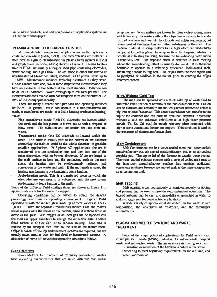
PLASMA ARC MEL TER CHARACTERISTICS A more detailed comparison of plasma arc melter systems is
contained elsewhere (Eddy, 1993). The term "plasma arc melters" is used here as a group classification for plasma ton:h melters (PTMs) and graphite-arc melters (GAMs) shown in Figure 1. Plasma torches used in PTMs are usually a long or short pipe containiilg electrodes, water coolin3, and a gas flow. The arc mode is either transferred or DOll-transferred (described later), operates in DC power levels up to 10 MW. Maintenance includes replacing electrodes as they wear. GAMs usually have one, two or three graphite rod electrodes and may have an electrode in the bottom of the melt chamber. Operation can be AC or OC powered. Power levels go up to 250 MW per unit The dectrodes are consumable with consumption rates on the order of 1-5 wt"/o of the throughput capacity.
There are many different configurations and operating methods for PAM. In general, PAM can operate in a non-transferred arc mode, a transferred arc mode, or a Joule-heating (resistance-heating) mode:
NOll-tnalferred mode: Both OC electrodes are located within the torch and the hot plasma is blown out as with a propane or blow torch. The radiation and convection heat the melt and waste. TnDlferred mode: One OC electrode is located within the torch. The other is usually part of the bottom of the chamber containing the melt or could be the whole chamber, in graphite crucible applications. In 3-pbase AC applications, the arc is transferred into the conducting mc:lt and then into one of the other electrodes, with no bottom electrode. If the arc length to the melt surface is long and the conducting path in the melt short, the heating may be predominantly radiation and convection to the waste and mdt If the arc length is short, the heating mechanism is predominantly Joule heating. Joule-beating mode: This is a transferred mode in which the electrodes are very near to or submerged into the melt giving predominantly Joule heating in the melt
Some of the different PAM configurations are shown in Figure I to approximate scale for the same throughput
Operating conditions can be varied to obtain the desired processing conditions or operating enviromnent. Typical PAM operation is with the molten gIass made up of metal oxides at 1,500-1,800 C. There are separate (immiscible) molten gIass and molten metal regions with the metal on the bottom., since it is three times as dense as the glass. Air, oxygen or an inert gas can be injected into the melt (or upper chamber) to change the oxidation state, liberate fixed carbon as CO or C�, or to enhance mixing. Feed size is limited by the feedport size, thus by the size of the melter itself otfgas is taken off the top and treatment systems are required, but are usually much smaller than for fuel-fin:d or incinerated systems. A discussion of some of the variable operating conditions follows.
Glass Melters Glass Melters for treatment of primarily nonmetallic wastes
have operating characteristics that are much different than metal
scrap meIters. Scrap melters are known for their violent arcing, noise and luminosity. In waste melters the objective is usually to liberate the hydrocarbons and possibly the chloride and sulfur compounds, but retain most of the hazardous and other substances in the melt. The metallic material in scrap mc:lters has a high electrical coociuctivity CCl1IlpIIml to molten glass. In scrap melters the long-arc radiation is beneficial in heating the scrap. because the Joule-heating contribution is relatively low. The opposite effect is obtained in glass melting where the Joule-heating effect is usually dominant. It is therefore desirable to operate in a relatively quiescent, Joule-heated melt, simulating a weak rolling boil. The offgas from the melt region can be pyrolyzed or oxidized in the melter prior to entering the offgas treatment system.
With/Without Cold Top· The melt can be operated with a thick cold top of waste feed to
minimize volatilization of hazardous and non-hazardous metals which can be oxidized and remain in the molten gIass or reduced to obtain a pig iron or steel feedstock. This condition reduces heat transfer to the top of the chamber and can produce pyrolized organics. Operating without a cold top enhances volatilization of high vapor pressure metals (Ph, Zn, Cd, etc.) for metals recovery when combined with high electric current and longer arc lengths. This condition is used in the treatment of electric arc furnace dust.
Melt Containment Melt Containment can be a water-cooled metal pot, water-cooled
metal/refractory pot, air-cooled metal/refractory pot, or an air-cooled graphite pot The top or lid of the furnace is usually water-cooled. The water-cooled pots can operate with a layer of cooled melt next to the innermost metallrefractory surface that provides additional corrosion resistance because the cooled mdt is the same composition as in the molten melt.
Melt Tappin, Melt tapping. either continuously or semicontinuously. or tipping
and pouring can be used to provide semicontinuous operation. The tapped material can be cast into monoliths or quenched in water to make an aggregate for construction applications.
A wide variety of options exist dependent on the waste stream composition. the objectives of treatment, and the throughput requirements.
PLASMA ARC MEL TER SYSTEMS AND WASTE TREATMENT
Some of the major potential applications for PAM systems are municipal 90lid waste (MSW), industrial hazardous waste, hospital waste, and radioactive waste. The major issues in treating waste are:
EIimination or reduction of the hazardous nature of the waste. Processing to meet regulatory requirements for the air, land, and water en,ironment
376
Recovery of useful products, to the extent economically practical. Volume reduction of the ultimate waste. For treatment alternatives, the proposed treatment must have
economic or other advantages over direct landfill options. Customers want the treatment process to do the following:
Tmat all kinds of heterogeneous waste. Result in no air emission. Result in no solid or liquid "ultimate" waste. Eliminate the customc:r's liability for the waste. Provide the treatment at little or no cost.
These goals are difficult, if not impossible to achieve, but the plasma arc melter systems come as close to accomplishing these goals as any system available.
PAM systems (PAMS) arc extremely robust, both in type of waste bandled and in flexibility of operation. They can treat almost all, if DOt all types of heterogeneous solid waste, most sludges and liquid wastes (though it may be impractical to treat dilute liquid wastes). In general, treatment will result in a primary solid product and an otfgas, that will have gaseous, fuming particulates, condensables, and inorganic compounds that can be precipitated in a scrubber. The primary product is a glass-ceramic product that can be a glass-like, rock-like, or glass-rock-like material. The glass-like product would be similar to obsidian; the rock-like product is similar to basalt, and the g1ass-rock is more crystalline than the glass. The otfgas products can be separated as appropriate. Pyrolysis and reforming can yield a syngas for liquid hydrocarbon generation or for cogeneration of electric power. R.etuming all the solidified otfgas products to the me1ter is an option, but in most CII.!ICS futile, because the non-solids will again volatilize, and in increasing proportions, thus taxing the otfgas system capabilities. Recycling could be advantageous in the case of high concentrations of high vapor pressure metals (HVPM), because a larger fraction of the HVPM can then be incorporated in the melt. Options depend on the composition of the waste. HVrM in the form of a secondary solid product is discussed below. If wammted, chlorides and sulfur compounds can be separated from the other condensable metals and oxides as a tertiary solid product Either dry-wet or wet-dry otfgas systems are used depending on the particular requjn:ments.
Optimum operation with P AMS utilizes oxygen or oxygenenriched air. As a result the exhaust gas emissions are greatly reduced from that of incinerators used in WTE plants, that are typically fired on air and have large amounts of nitrogen in the otfgas. Exhaust gas recirculation (like in an automobile) can be used for temperature control. Because of the reduced otfgas flow rate, the air pollution control systems arc reduced in size and emissions are reduced. With an appropriate otfgas control system, all regulations can be met with large safety factors. The exhaust gases are Co" water vapor, and some N2. NOx is, rarely an issue because the low nitrogen content combined with temperature control results in negligible NOx formation.
The solid and liquid "ultimate" waste effluent is negligible if not eliminated The primary product can be recycled as aggregate, bricks, or a higher-valued product. Depending on the economics, three options exist for the condensables: I) use to form a low-tcmpcrature construction product, 2) store until extractive metallurgy can be done in quantity of the metals, or 3) send to a classified landfill. The
377
chloride and sulfur precipitates can be used to augment road salt mixtures or disposed of. as appropriate for the local area.
The initial waste characteristics are totally altered by the treatment process. Liability for the original waste is eliminated or assumed by the pun:haser of the (raw) product. This feature is a major consideration for industrial hazardous wastes.
For large systems, c.g., several hundred tonneslday, the installation of a P AMS can provide an economic advantage, even over that of the present WTE plants. The tipping fee represents a � raw material cost, which is a bonus for a manufacturing or industrial business. The waste haulers stilI get their business. The processing plant simply replaces the landfill, eliminating all the problems associated therewith and turning the waste into a raw material for producing useful products. Plan1s operate around the clock, with a 700At or higher duty cycle. Specific economics are discussed later.
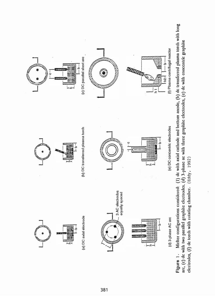
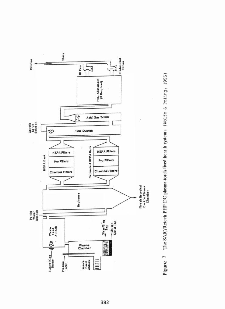
PAM pilot plants have been built and operated for a number of applications. The U.S. Department of Energy has funded demonstration work on both PTM and GAM treatmt:nt of low-level radioactive and hazardous wastes. Much of this waste is similar to MSW. Most of the pilot plants used in recent OOE-fimded research range in size up to approximately l-tonnelhour, are operational, and are available for testing. A Retech PTM with a rotating chamber that taps when the rotation slows (see Fig. 2) is installed at the Western Environmental Center operated by Mountain States Energy in Butte, Montana (Rutmcr, 1994). A similar, but larger, unit is to be used in treatment demonstrations of Pit 9 at the Idaho National Engineering Laboratory. Another Retecl1 PTM is employed by SAlC in the plasma hearth melter configuration (see Fig. 3, Wolfe, 1995). Preliminary cold testing was done at Retech in Ukiah, California and at the SAlC STAR Center in Idaho Falls, Idaho. Electro-Pyrolysis, Inc. installed and tested a GAM with concentric graphite electrodes and a graphite chamber at Massachusetts Institute ofTechnology (see Fig. 4, Watkins, 1993).
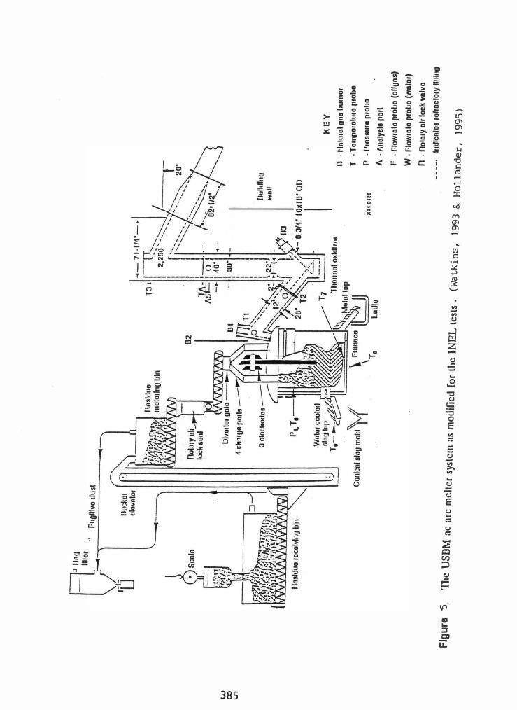
The American Society of Mechanical Engineers and the U.S. Bureau of Mines sponsored a project on vitrification of incinerator ash from a variety of municipal incinerators using a 3-pbase AC GAM (Hollander, 1995). This facility has been modified by the Bureau of Mines and the Department of Energy to treat combustible waste, operates at near capacity of l-tonlh, and is one of the most complete pilot plants available as a user test facility (see Fig. 5, Soelberg,I995). Many other PAM test facilities and installations are discussed elsewhere (Eddy, 1992). The above pilot plants have demonstrated the robust processing of heterogeneous waste streams, including combustibles, and the generation of extremely stable waste form products that meet regulatory requirements.
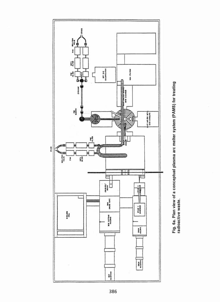
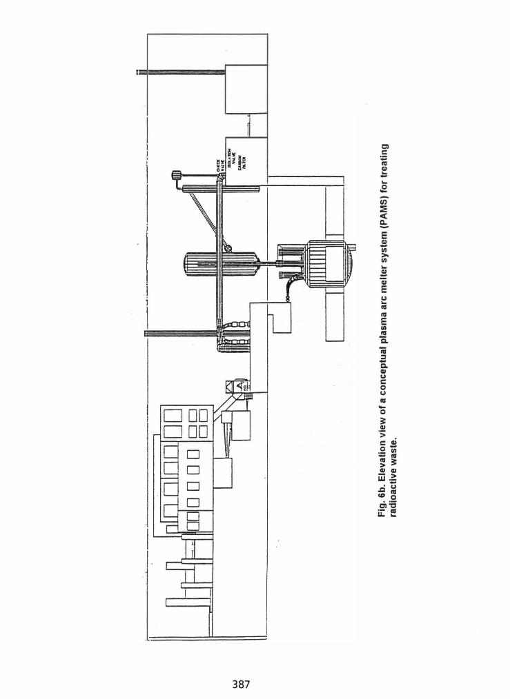
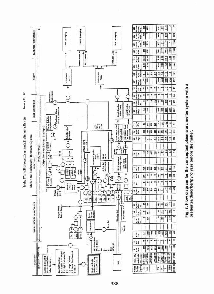
TYPICAL PLASMA ARC MEL TER SYSTEMS A conceptual plasma arc melter system is shown in plan view in
Fig. 6a and in elevation in Fig. 6b. This system is a 1 -5 MW PAMS for treating radioactive and hazardous waste. Corresponding flow diagrams are shown in Fig. 7 (with a preheater/pyrolizer before the melter) and Fig. 8 (without the preheater/pyrolizer) as shown in Fig. 6. Flow xates are given in Fig. 7 for selected components and different input waste streams. The system shown is for low-level radioactive waste treatment based on a l-tonneJh throughput, which is relatively small for MSW plants. MSW applications are expected to be from 200 to 1000 tonne/day throughput capacity. For larger
flow rates, the values in Fig. 7 can be considered as on a tonne/h basis. The illust"ntions are for a low-level radioactive waste with six major heterogeneous input waste streams that are predominantly glass (G 1), metal (Ml), combustibles (C5), PortIand-cc:mented orpnics (P), organic liquids adsorbed in Oil-dri (S), and a hydrated meta1 oxide sludge in drums (lIDl) as described elsewhere (Eddy, 1992 4: 1995). The combustible stream, C5, is the closest to MSW.
Froot-end staging will be similar to that for WIE plants. The feedstock would be prepared through appropriate shredding systems that would size the material relative to the size of the melter system with a nominal size of 2 to 6 inches. In small systems, sizing will be necessary to be able to feed the material into the melter in a sufficiently dense form to meet power-density capabilities of melters.
Several melter configurations are shown in Figure I. Additional options include the cupola and non-transfcrred torch system of Westinghouse (McLaughlin, 1995) and the "silo" and non-transferred Acrospaciale torch used by EuropIasma and INERTAM (Francois, 1994). The selection of a P AMS is affected by the composition of the waste, the recovery methods to be applied, and the sizing requirements. For more than 240 tonnesIday, an MSW plant would require more than 10 MW of melter power, which may be more conveniently obtained with one GAM or multiple P1M systems. Esxntially all of the systems will work., but some will have economic advantages not achievable by others.
For large systems, production of a syngas to produce liquid hydrocarbons is advantageous because of the higher-value-added product. The capital cost and minimum throughput capacity requirements for a methanol system dictate capacities larger than 200 tonnesIday. Site-specific economic studies are required to justify this option.
For medium-sized and larger systems, cogeneration of electricity and/or district heating is an option. A medium heating value fuel gas can be generated that is about 400 Btu/� compared to 1,000 Btu 1ft! for natural gas. Cogeneration of electricity can be accomplished with gas-turbine generators for lower capacities, steam-turbine generators for large capacities, and combined systems for intermediate capacities. Calculations indicate that more power is generated than used by the melter and auxiliaries; hence, electric power can be marketed.
The primary waste form or solid product is a g1ass-ccramic and can be recycled as a low-value aggregate for construction or cast into bricks or other higher-value construction products. The size and sophistication of the casting plant depends on the MSW plant capacity. The aggregate is made by tapping the molten glass into water whereby it is granulated by the rapid qUCDching. Casting plants would emulate metal casting plants, with the appropriate modifications for glass-«ramic versus metallic melts.
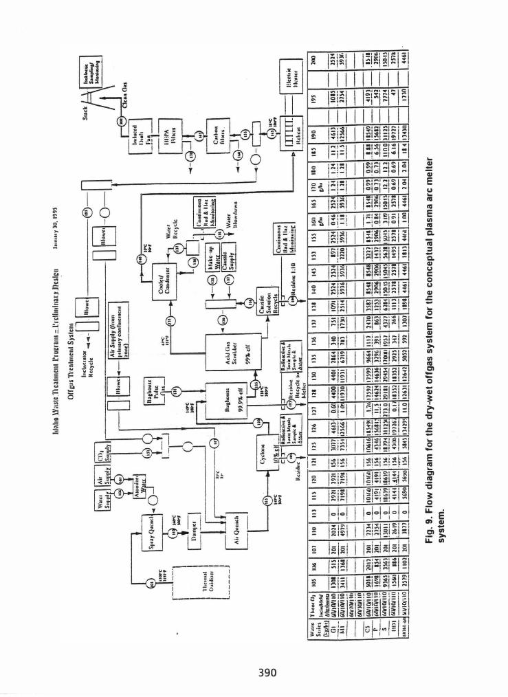
Otfgas control can be achieved using "dry-wet," "wet-dry," or "dry" otfgas control systems. A dry-wet otfgas treatment system (see Fig. 9) can be used for separating filtered particulate from the salts of scrubbed acid gases for return to the melter, generation of a secondary solid construction product, or special waste stabilization and disposal. Typical components can include a post combustor (to efficiently oxidize pyrolysis products), spray� quench, air qucru;h, cyclone, baghousc filter, acid-gas scrubber, reheat, prefilter, activated carbon filter, HEPA filter, and stack. Three major output streams exit as dry particulates collected in the cyclone and baghouse, scrubber solution with dissolved and undissolved material. and the
cleaned gaseous exhaust. Inclusion of final filtration equipment downs1ream of the wet scrubber may be unnecessary for most systems except those designed for processing radioactive waste. The extremely small amonnt of material reaching the prefilter, carbon, and HEPA filters can be returned to the melter by shredding the filters and feeding than into the melt Otherwise. the filters can be reactivated with the contaminants being returned to the melter, stabilized in the sccoodary product, or disposed of separately.
Dry otfgas treatment systems use sorbent injection upstream of the beghouse to scrub acid gases in the baghouse. This eIiminates the wet scrubbing step and can result in a single dry secondary waste form.
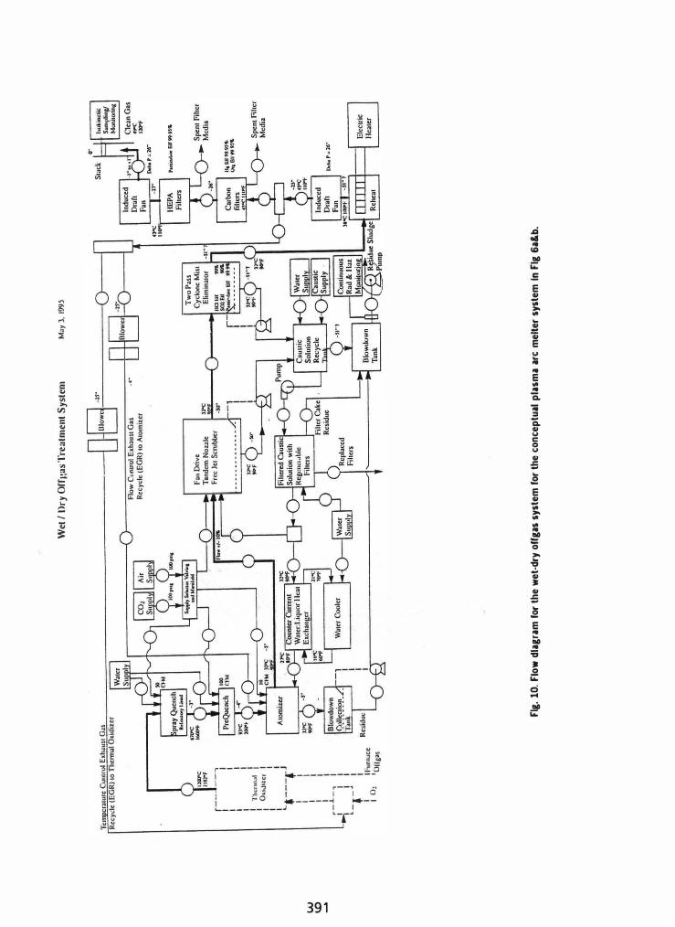
A wet-dry otfgas treatment system (see Fig. 10) can be used when one secondary waste form or product is appropriate. This is the otfgas system shown in Fig. 6a&b. The particulates and acid gas salts are collected together in the scrubber sludge and marketed or disposed of as discussed above. This system precludes the formation of dioxins, gives a much more compact otfgas system with lower capital cost than the dry-wet system. Typical components can include a post combustor, a spray quench and acid gas scrubber, demister, rehcater, and prefilter, activated carbon, and HEPA filters as appropriate, and stack.
The actual otfgas treatment system for a PAMS recovery plant will depend on the plant components. In a P AMS with a methanol plant, electrical cogeneration, and a brick plant, the melter would be the first stage of reforming the syngas, followed by a syngas reactor, a syngas cleanup system for removing condensables and particulates, as well as the chlorine and sulfur compounds, the methanol plant, the cogeneration plant which provides the secondary combustion and appropriate final filters.
ECONOMICS Present assumptions represent approximations based on the
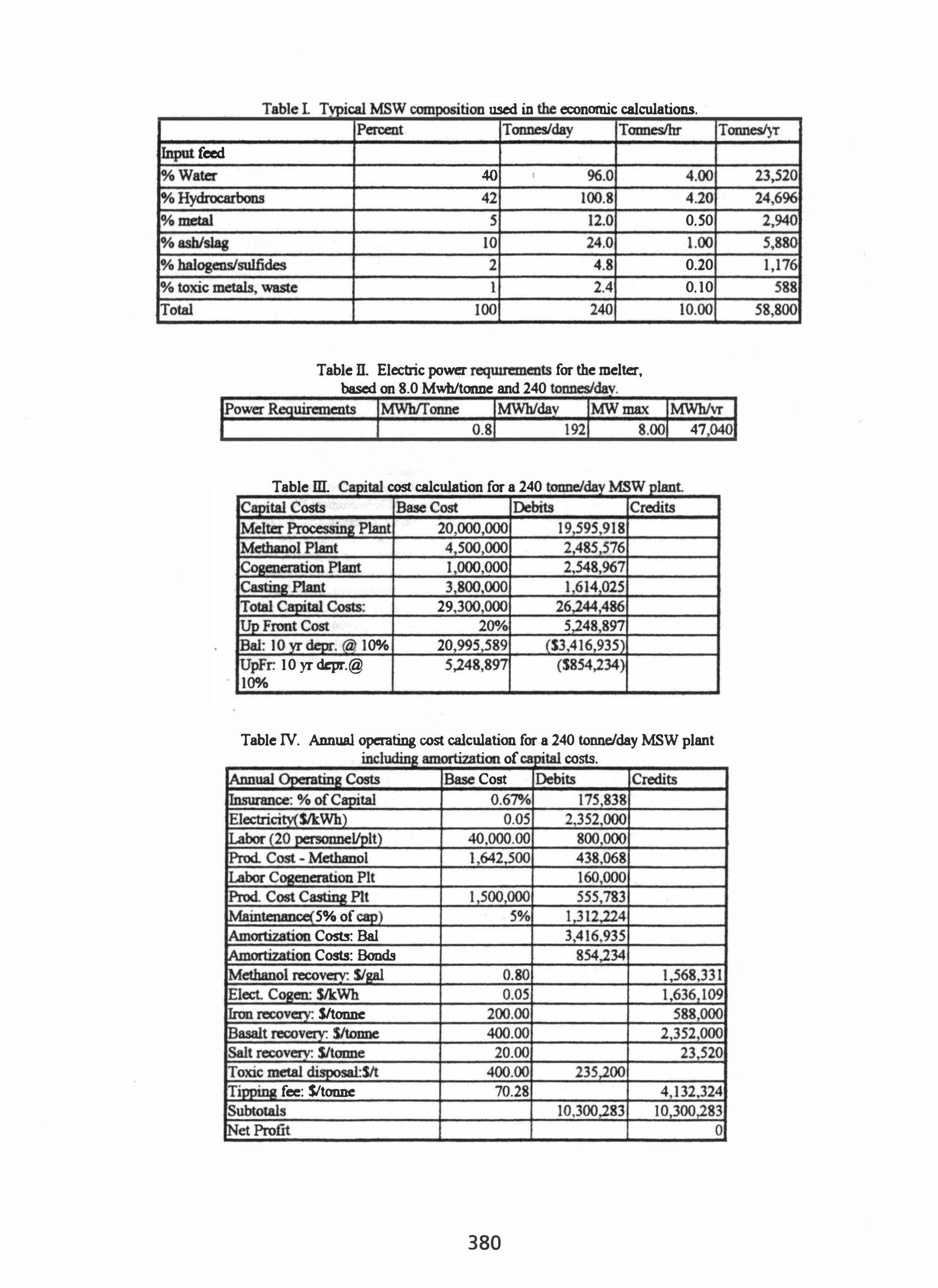
selected scenario. For an actual location, cost values are site-specific and estimates must be made in detail for that site. A typical composition ofMSW is given in Table I for the economic calculations in this paper. Typical flow rates are given for an input of 240 tonncslday. The concentrations are limited to the major components
. for the economic calculations. Other calculations, not included here, are used to design the components to obtain the desired efficiency.
The potential partitioning of the MSW can be estimated from the compositions given in Table I. The composition used is similar to a Class 2 refuse with about a 60/40 rubbish/garbage split The water (40 wt"A.) will be either exhausted, partially condensed, or used in reforming the syngas. The hydrocarbons (42 wt%) can be partially converted into liquid organics and/or burned in a cogeneration plant. The mctaI (5 wt"A.) is salvageable as a pig iron. The ash residue (10 wt"A.) can be made into aggregate or bricks. For this example it is assumed that the ultimate hazardous waste is as large as I-wt%, which could be a component of a low temperatme concrete. Each MSW treatment site must be evaluated for the typical composition of its waste to obtain valid product flow rates and economics.
The data for the calculations were run under certain assumptions. Uuits are in Standard International Uuits (metric tonnes, etc.). Currency is in US Dollars. Plant operating duty cycle is 70% with a 5-shift, around the clock operation. Base plant costs were used as reference to calculate the current plant costs corrcctcd
378
for size. A 250 tonne/day melter processing plant is estimated to cost 520,000,000. A 60 tonne/day methanol plant cost is estimated at $4,500,000. A combined cycle cogeneration plant costs $750,000 per MWh. A 100 tonne/day casting plant costs 53,800,000. A 100 tonneIday aggregate plant costs 113 of a casting plant Estimated product recovery lDlit costs include methanol at SO.80 per US gallon, electricity bought/sold at. SO.05 per kWh, and scrap iron at $l00/tonne. The basalt by-product is made into bricks and sold for an estimated SO.40 per brick or $400 per tonne. Salt (sodium chloride) has a �e value of$l0 per tonne. Toxic metals and waste can be disposed of for $400 per tODDe. Operating cost assumptions included insurance that could be arranged for 0.670A, of the capital cost Labor for S-shift operation would require 20 personnel at the melter facility, with additional personnel as needed for the product plants. Salaries averaged S4Q,OOO per year. Annual maintenance costs are assmned as 5% of capital costs.
Table n gives the electric power requirements for the melter, based on 8.0 Mwbltonne for a 240 tonne/day MSW plant Tables ill and N give the capital cost and operating cost values for the same plant assuming methanol generation, electric cogeneration, and a brick plant in operation.
It is important to know the capacity ranges when the various product options become economical. These are site specific. Typical examples are plotted in Fig. II for the MSW composition considered here. The options coosidered are based on combined cycle cogeneration systems. The plot gives the effective tipping fee (negative raw material cost) in Sltonne versus throughput in tonnes/day. The tipping fee is that required to reach the breakeven point at that capacity. Front end costs, amortiz.!tion of capital costs, and operating costs are included.
As expected, at low throughput the tipping fees would need to be astronomical to pay for the treatment costs. Some Class I landfills are charging S4OOltonne, so at 30 tonnesfday, some hazardous wastes could be treated economically (<$400ltonne tipping fee). Stabilization costs for electric arc furnace dust are between 200 and 300 $/tonne, so processing rates of around 100 tonnesIday are economical. This is also affected by zinc prices. For MSW, tipping fees range from SI5ltonne in the Western U.S., to between 60 and 120 S/tonne in the East; therefore, the MSW plant size threshold is about 200 tonnes/day.
The more value-added product options, the lower the cost However, the difference added by the methanol option may only be justified at the largest throughputs. These plots are shown as examples only. For accurate results, site-specific data must be used.
Cost differences using gas turbine generators, steam turbine generators, and combined cycle power plants were also evaluated. Even though their base costs were different, there was little difference indicated between the cogeneration options over the throughputs of Fig. 9 when added to the rest of the system. costs.
CONCLUSIONS Though there are 00 operating plasma arc melter MSW
treatment systems, the success of WfE plants, the design of similar plants using commercially available equipment, and the potential environmental and economic advantages of PAMS for large capacity systems indicates that PAMS are probably the om generation in environmental solutions.
REFERENCES Eddy, 1. L., et aI. Thermal Processing Sy:rtem Concepts and
Eddy, T.L., et aI., Plasma/Arc Melter review for Vitrification of Mixed Wastes: Results, Proc. Int. Symp. EITVironmentol Technologiu: Plasma Sy:rtem3 and ApplicatiOlU, pp. 227-238, Atlanta, Georgia, Oct. 8-11, 1995.
Francois, D., Installation de Traitment de gal issus d'tm four d'incineration de dechets aimiantiferes: INERTAM, ActuIProc. Symp03ium Intenwtional. Inertoge et Valorizatiion des Decheu Ultimes, pp. 1156-1 to 2, Bordeaux, France, Sept 12-14, 1994.
Hilts, M.E., Recycling and Waste-to-Energy Side by Side: From Concept to Reality, Solid Waste Technologiu , Vol. vm. No.4, pp. 12-17, July/August, 1994.
Hollander, H.I., et aI., ASME/US Bureau of Mines Investigative Program on Vitrification of Combustion AshIResidue, Proc. Int. Symp. Environmental Technologies: Plasma Systems and ApplicatiOlU, pp. 333-353, Atlanta, Georgia, Oct. 8-11, 1995.
McLaughlin, D.F., et aI., Plasma Processing for the Treatment and Immobilization of Radioactive Tank Waste, Proc. Int. Symp. Environmentol Technologiu: Plasma System3 and Applications, pp. 481-491, Atlanta, Georgia, Oct. 8-11, 1995.
Molten Metal Teclmology, Inc., Waltham, Massachusetts, 1993. Ruffuer, J.W. , and T. Rivers, Design and Performance of an
Offgas cleaning system for the Plasma Arc Centrifugal Treatment System, ActuIProc. Symposium International. lnertage et Valorizatiion des Decheu Wtimes, pp. 1137-1 to I S, Bordeaux, France, Sept 12-14, 1994.
Soelberg, N.R., et aI., Arc Melter Vitrification of Organic and Chloride Containated Soils, Proc. Int. Symp. EITVironmentol Technologiu: Plasma Systems and Applications, pp. 227-238, Atlanta, Georgia, Oct 8-11, 1995.
Watkins, J.L., et al., Test Plan: FY93 Mark I/.IX Arc Furnace Tests, Pacific Northwest Laboratory, Richland, Washington, October, 1993.
Wolfe, W.P., and S.D. Poling, Plasma Hearth Process Hardware Development, Int. s..vmp. Environmental Technologies: Plasma s..vstem:r and Applications, Atlanta, Georgia, Oct. 8-11, 1995.
PAM'" is a trademarl: of Me ItT ran, Inc.
379
feed
used in economic calculations.
I
40 '
Table n. Elecbic power ' for the melter,
TableID.
based on 8.0 Mwhltonne and 240
MWhITonne max
cost calcnlation for a 240
29
. I ()O/O 20 . 10 yr depr.@
I()o/o
0.50
1.00
0.20
0.10
47
Table N. Annual operating cost calculation for a 240 tonne/day MSW plant . . . .