35
F14-109 February, 1997 INSTRUCTION MANUAL for the ETCHARC PLASMA MARKING SYSTEM 411 South Ebenezer Road Florence, SC 29501-0545
F14-109
February, 1997
INSTRUCTION MANUAL for the
ETCHARCPLASMA MARKING SYSTEM
411 South Ebenezer RoadFlorence, SC 29501-0545
ESAB Cutting Systems, 1997
This manual is ESAB Part Number F14109
This manual is intended for the convenience and use of the cuttingmachine purchaser. It is not a contract or other obligation on thepart of ESAB.
Printed In U.S.A.

EtchArc Plasma Marker
Contents
1 Safety....................................................................................................1
1.1 Introduction ...............................................................................1
1.2 General Safety Information........................................................2
1.3 Plasma Marking Precautions .....................................................3
1.3.1 Electrical Shock Prevention ...........................................3
1.3.2 Eye Safety .....................................................................3
1.4 Skin Safety ................................................................................4
1.5 Electrical Grounding ..................................................................4
2 Introduction ...........................................................................................5
2.1 Overview ...................................................................................5
2.2 System Description....................................................................6
3 Installation.............................................................................................7
3.1 Interface ....................................................................................7
3.2 Requirements ............................................................................8
4 Setup ....................................................................................................9
4.1 PCM-500i Setup ........................................................................9
4.2 Gas Setup ...............................................................................10
4.3 CNC Setup ..............................................................................11
5 Process Data ......................................................................................12
6 Maintenance .......................................................................................19
6.1 Routine Maintenance...............................................................19
6.2 System Interface .....................................................................20
6.3 Pressure Switch Adjustment....................................................21
7 Replacement Parts..............................................................................22
7.1 General Information.................................................................22
7.2 Ordering Information ...............................................................23
7.3 Plasma Marker System ...........................................................24
7.4 Marker Power Supply Assembly..............................................26
7.5 Plasma Marking Torch.............................................................28
7.6 Torch Lead Assembly..............................................................30
EtchArc Plasma Marker
Safety Page 1
1 Safety
1.1 Introduction
ESAB arc marking products are designed toprovide both safety and efficiency in operation.However, sensible attention to operatingprocedures, precautions, and safe practices isnecessary to achieve a full measure of safety.Whether an individual is involved with operation,servicing, or as an observer, compliance withestablished precautions and safe practices must beaccomplished. Failure to observe certainprecautions could result in serious injury topersonnel or severe damage to the equipment.The following precautions are specific guidelinesapplicable to the plasma marking process. Moregeneral precautions are presented in the instructionliterature pertaining to the cutting machine.

Section 1
Page 2 Safety
1.2 General Safety Information
All personnel, materials, and equipment notinvolved in the production process must bekept clear of the entire system area. Onlyqualified personnel should be allowed tooperate or service the equipment.
Read entirely through a procedure to becomefamiliar with the task before operating orperforming maintenance on any part of thesystem. Special attention must be given to allWARNINGS, CAUTIONS, and NOTES whichprovide essential information regardingpersonnel safety and/or possible damage toequipment.
All safety precautions relevant to electricalequipment and the process operations mustbe strictly observed by all who haveresponsibility or access to the system. DONOT touch the plasma marking torch duringoperation. Do not operate any part of thesystem with any of the protective coversremoved or electrical component boxes open.Refer to all safety publications made availableby your company.
Fence off the entire work cell to preventpersonnel from passing through the area orstanding within the working envelope of theequipment. Post appropriate CAUTION signsat every entrance to the work cell area.

EtchArc Plasma Marker
Safety Page 3
1.3 Plasma Marking Precautions
1.3.1 Electrical Shock Prevention
The plasma arc marking process employs highvoltages. High voltage can kill. Do NOT touch themarking torch, cutting table or cable connectionsduring the plasma cutting process.
Electrical Shock Can Kill You!
• Always turn off power to the plasma powersupplies before touching or servicing a plasmamarking torch.
• Always turn off power to the plasma powersupplies before opening or servicing the plasmapower supply or interface box.
• Do not touch live electrical parts.
• Keep all panels and covers in place when themachine is connected to a power source.
• Insulate yourself from the workpiece andelectrical ground: wear insulating gloves, shoesand clothing.
• Keep gloves, shoes, clothing, work area, andthis equipment dry.
1.3.2 Eye Safety
Arc rays can injure eyes and burn skin.
To protect your eyes from burns caused by highintensity ultraviolet light, sparks and hot metal :
• Do not look at the arc.
• Wear correct eye protection. Wear dark safetyglasses or goggles with side shields.
• Replace glasses/goggles when the lensesbecome pitted or broken
• Warn other people in the area not to look
Section 1
Page 4 Safety
directly at the arc unless they wear appropriatesafety glasses.
• Prepare the cutting area in a manner thatreduces the reflection and transmission ofultraviolet light:
• Paint walls and other surfaces with dark colorsto reduce reflections.
• Install protective screens or curtains to reduceultraviolet transmission.
1.4 Skin Safety
To protect skin against burns caused by highintensity ultraviolet light, sparks and hot metal:
• Wear protective clothing:
• Wear gauntlet gloves.
• Wear flame-retardant clothing which covers allexposed areas.
• Wear cuffless trousers to prevent entry ofsparks and slag.
• Do not touch the torch when it is about to startor while marking. After marking, allow time forthe front of the torch to cool.
1.5 Electrical Grounding
Electrical grounding is imperative for propermachine operation as well as for SAFETY.
All ESAB Shape Cutting Machines must have agood electrical connection to earth ground.

EtchArc Plasma Marker
Introduction Page 5
2 Introduction
2.1 Overview
The EtchArc Plasma Marker is a constricted arcplasma torch marking device. The plasma markeris a low amperage plasma torch designed for highaccuracy line marking on metal plate. It produceshigh quality, durable marks at speeds between 100and 500 inches per minute. It can greatly enhanceproduction by performing plate layout and markingwith computer controlled accuracy and speed.
The plasma marking process is similar to theplasma cutting process. However, rather thanmaking a cut into the plate, the low amperageplasma arc merely marks the plate in the patternproduced by the machine motion. Voltage heightcontrol maintains a constant torch standoff forconsistent marking. This allows for high speed,highly accurate pattern layout.
When the EtchArc Plasma Marker is used inconjunction with ESAB’s Vision CNC, DynamicCurrent Control is used to precisely control widthand depth of marks by proportionally rampingcurrent up and down as the machine accelleratesand decelerates. This minimizes cratering or pittingon starts, in corners, and at the end of the mark.
The Plasma Marker system is intended to be usedduring an automatic cutting cycle. Accuratepositioning of the layout lines and marks dependson using the automatic marker offsets executed bythe CNC during Automatic Mode. However, themarker can be used manually for the purpose oftesting and setup.
For automatic operation the control will execute thenecessary steps, according to the part program, tooffset the torch, turn on the Automatic HeightControl, fire the torch, and begin marking.
For manual operation, all of these steps must beperformed by the operator.

Section 2
Page 6 Introduction
2.2 System Description
The Plasma Marking System consists of a modifiedPCM-500i plasma power supply, a marker add-onbox, the marking torch, and Argon supply regulator.
The PCM-500i is an inverter power supply capableof supplying 35 Amps. It is modified to interfacewith a CNC, and the manual controls are disabledto prevent accidental misadjustment.
The marker add-on box interfaces the markingtorch to the power supply, providing the necessaryelectrical connections, pilot arc control, andadditional gas control.
The marking torch is designed for simplicity andlong consummable life. There are only threeconsummable parts, the electrode, nozzle, andshield cup. Argon cut gas provides long electrodeand nozzle life.

EtchArc Plasma Marker
Installation Page 7
3 Installation
3.1 Interface
The EtchArc Plasma Marker system is designed tobe interfaced with any cutting machine controller viathe standard ESP open interface. This interfaceprovides an amphenol connector to which thecustomer may connect the appropriate controlwiring.
The schematic below shows the standard ESPopen interface, as it must be used with the plasmamarking system. When interfacing with a controlother than the ESAB Vision CNC or Series 2000CNC, the customer must provide the externalrequirements shown below.
ESP Interface
Section 3
Page 8 Installation
3.2 Requirements
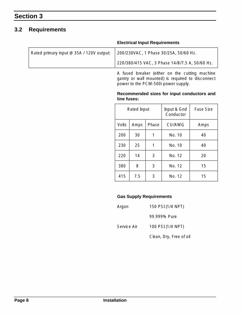
Electrical Input Requirements
Rated primary input @ 35A / 120V output: 200/230VAC, 1 Phase 30/25A, 50/60 Hz.
220/380/415 VAC, 3 Phase 14/8/7.5 A, 50/60 Hz.
A fused breaker (either on the cutting machinegantry or wall mounted) is required to disconnectpower to the PCM-500i power supply.
Recommended sizes for input conductors andline fuses:
Rated Input Input & GndConductor
Fuse Size
Volts Amps Phase CU/AWG Amps
200 30 1 No. 10 40
230 25 1 No. 10 40
220 14 3 No. 12 20
380 8 3 No. 12 15
415 7.5 3 No. 12 15
Gas Supply Requirements
Argon 150 PSI (1/4 NPT)
99.999% Pure
Service Air 100 PSI (1/4 NPT)
Clean, Dry, Free of oil

EtchArc Plasma Marker
Setup Page 9
4 Setup
4.1 PCM-500i Setup
The control panel of the PCM-500i should be setproperly prior to marking operation. Check thefollowing items:
AIR TEST - Place this switch in the OPERATEposition for normal operation.
TRIGGER LOCK - This switch is disconnected,and has no effect.
CURRENT CONTROL - The Current Control knobcan be left in any position. Plasma Marking currentis controlled by the cutting machine CNC.
POWER - The Power On lamp should be on.
FAULT - The Fault lamp should be off.

Section 4
Page 10 Setup
4.2 Gas Setup
The Plasma Marking System uses two compressedgases for operation. Compressed air is used forelectrode cooling and shield gas, Argon is used asthe plasma gas. The plasma gas constricts the arcas it exits through the nozzle orifice. The shield gascreates a secondary shield around the arc, andimproves torch cooling.
Before operating the system, be sure to check thegas pressure settings for both compressed gases.
The TEST/OPERATE switch on the front panel ofthe PCM-500i allows the operator to preset thepressure for both gases. Set this switch to theTEST position to energize the solenoid valves forboth compressed air and Argon.
At the PCM-500i, adjust the Air Pressure Regulatoron the rear of the unit while observing the pressuregauge on the front of the unit. Set the pressure to90 PSI while the air is flowing.
The Argon pressure is adjusted at the separateregulator panel mounted to the cutting machine.
While the Argon is flowing, set the pressure to 75PSI.
When finished adjusting the gas pressures, set theTEST/OPERATE switch back to the OPERATEposition.

EtchArc Plasma Marker
Setup Page 11
4.3 CNC Setup
The EtchArc plasma marker may be interfaced toany cutting machine CNC. The followingparameters may or may not be supported by yourinterface. Prior to plasma marking, check theseparameters, or their equivalents, at the machinecontrol:
Standoff On the Vision CNC, this parameter adjusts theactual cutting height (or arc voltage) that the torchwill maintain, after the arc has started.
Initial Height Sets the distance to raise the torch after sensingthe plate. When VHC is turned on, the torch willlower to the plate, then retract this distance beforestarting the arc.
Marker RemoteCurrent
On the Vision CNC, this parameter sets the markingcurrent in Amperes.
Refer to Section 5 of this manual for the appropriatevalues for each of these parameters.
Refer to the machine manual for detailedinstructions on how to change process parametersettings.

Section 5
Page 12 Process Data
5 Process Data
The Etcharc Plasma Marker can produce markedlines in a wide range of widths and depths, rangingfrom poor to excellent quality. It can also operateover a wide range of speeds. The operator mustbalance these two factors based on therequirements for a specific job.
The following pages provide process data for thesix different amperage settings. Each page showsthe setup parameters for that amperage, and achart with marking speed range. From the chart,the operator should select the speed setting basedon the quality of mark that can be accepted.

EtchArc Plasma Marker
Process Data Page 13
10 Amp Marking
CURRENT: 10 Amps
NOZZLE: .030” PN: 56996876
MATERIAL: CARBON STEEL
PLASMA GAS: ARGON @ 75 PSI (5 bar)
SHIELD GAS: AIR @ 90 PSI (6 bar)
PIERCE HEIGHT: .125” (3 mm)
ARC VOLTAGE: 66
Travel PlasmaSpeed Mark
inch/min mm/min Width Depth Quality
100 2540 .040”-.050” .0013 FAIR
200 5080 .040"-.050" .0005 GOOD
300 7620 .040"-.050" .0004 GOOD
400 10160 .040"-.050" .0004 EXCELLENT
500 12700 .040"-.050" .0003 EXCELLENT
Notes
1. Corner current set for 5 Amps in machine MIP.
2. Slow travel speeds usually have top spatter on mark edges.
3. Width and depth of mark will vary slightly depending on measuring methods. This information is forestimated results.

Section 5
Page 14 Process Data
15 Amp Marking
CURRENT: 15 Amps
NOZZLE: .030” PN: 56996876
MATERIAL: CARBON STEEL
PLASMA GAS: ARGON @ 75 PSI (5 bar)
SHIELD GAS: AIR @ 90 PSI (6 bar)
PIERCE HEIGHT: .125” (3 mm)
ARC VOLTAGE: 66
Travel PlasmaSpeed Mark
inch/min mm/min Width Depth Quality
100 2540 .040”-.050” .0043 POOR
200 5080 .040"-.050" .0021 FAIR
300 7620 .040"-.050" .0013 GOOD
400 10160 .040"-.050" .0003 EXCELLENT
500 12700 .040"-.050" .0002 EXCELLENT
Notes
1. Corner current set for 5 Amps in machine MIP.
2. Slow travel speeds usually have top spatter on mark edges.
3. Width and depth of mark will vary slightly depending on measuring methods. This information is forestimated results.
EtchArc Plasma Marker
Process Data Page 15
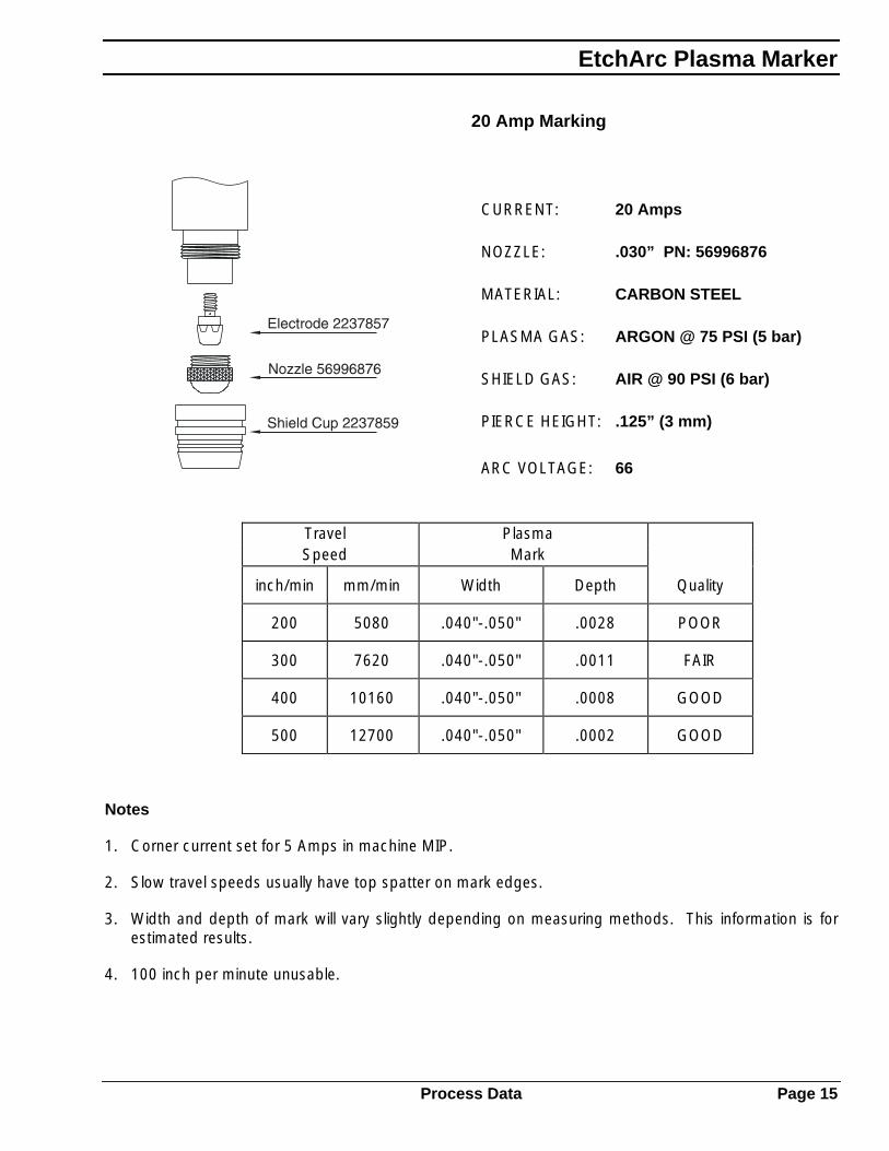
20 Amp Marking
CURRENT: 20 Amps
NOZZLE: .030” PN: 56996876
MATERIAL: CARBON STEEL
PLASMA GAS: ARGON @ 75 PSI (5 bar)
SHIELD GAS: AIR @ 90 PSI (6 bar)
PIERCE HEIGHT: .125” (3 mm)
ARC VOLTAGE: 66
Travel PlasmaSpeed Mark
inch/min mm/min Width Depth Quality
200 5080 .040"-.050" .0028 POOR
300 7620 .040"-.050" .0011 FAIR
400 10160 .040"-.050" .0008 GOOD
500 12700 .040"-.050" .0002 GOOD
Notes
1. Corner current set for 5 Amps in machine MIP.
2. Slow travel speeds usually have top spatter on mark edges.
3. Width and depth of mark will vary slightly depending on measuring methods. This information is forestimated results.
4. 100 inch per minute unusable.

Section 5
Page 16 Process Data
25 Amp Marking
CURRENT: 25 Amps
NOZZLE: .040” PN: 2237858
MATERIAL: CARBON STEEL
PLASMA GAS: ARGON @ 75 PSI (5 bar)
SHIELD GAS: AIR @ 90 PSI (6 bar)
PIERCE HEIGHT: .125” (3 mm)
ARC VOLTAGE: 66
Travel PlasmaSpeed Mark
inch/min mm/min Width Depth Quality
200 5080 .050"-.060" .0051 POOR
300 7620 .050"-.060" .0034 FAIR
400 10160 .050"-.060" .0032 GOOD
500 12700 .050"-.060" .0014 GOOD
Notes
1. Corner current set for 5 Amps in machine MIP.
2. Slow travel speeds usually have top spatter on mark edges.
3. Width and depth of mark will vary slightly depending on measuring methods. This information is forestimated results.
4. 100 inch per minute unusable.

EtchArc Plasma Marker
Process Data Page 17
30 Amp Marking
CURRENT: 30 Amps
NOZZLE: .040” PN: 2237858
MATERIAL: CARBON STEEL
PLASMA GAS: ARGON @ 75 PSI (5 bar)
SHIELD GAS: AIR @ 90 PSI (6 bar)
PIERCE HEIGHT: .125” (3 mm)
ARC VOLTAGE: 66
Travel PlasmaSpeed Mark
inch/min mm/min Width Depth Quality
200 5080 .050"-.060" .0033 POOR
300 7620 .050"-.060" .0030 FAIR
400 10160 .050"-.060" .0023 FAIR
500 12700 .050"-.060" .0029 GOOD
Notes
1. Corner current set for 5 Amps in machine MIP.
2. Slow travel speeds usually have top spatter on mark edges.
3. Width and depth of mark will vary slightly depending on measuring methods. This information is forestimated results.
4. 100 inch per minute unusable.

Section 5
Page 18 Process Data
35 Amp Marking
CURRENT: 35 Amps
NOZZLE: .040” PN: 2237858
MATERIAL: CARBON STEEL
PLASMA GAS: ARGON @ 75 PSI (5 bar)
SHIELD GAS: AIR @ 90 PSI (6 bar)
PIERCE HEIGHT: .125” (3 mm)
ARC VOLTAGE: 66
Travel PlasmaSpeed Mark
inch/min mm/min Width Depth Quality
300 7620 .050"-.060" .0012 POOR
400 10160 .050"-.060" .0024 FAIR
500 12700 .050"-.060" .0032 FAIR
Notes
1. Corner current set for 5 Amps in machine MIP.
2. Slow travel speeds usually have top spatter on mark edges.
3. Width and depth of mark will vary slightly depending on measuring methods. This information is forestimated results.
4. 100 and 200 inch per minute unusable.

EtchArc Plasma Marker
Maintenance Page 19
6 Maintenance
The Plasma Marking System consists of a PCM-500i plasma power supply, a marker add-on box,the marking torch, and Argon supply. Maintenanceof the PCM-500i plasma power supply is covered inthat unit’s instruction manual, form F15-296.
6.1 Routine Maintenance
The following routine maintenance should beperformed on the plasma marker system.
• Inspect the supply hoses, torch leads, groundcable, and interface cables for damage or wearat least weekly.
• Inspect and clean the PCM-500i at leastmonthly. The unit can be blown out using aclean, dry gas source, such as compressed airor nitrogen.
Section 6
Page 20 Maintenance
6.2 System Interface
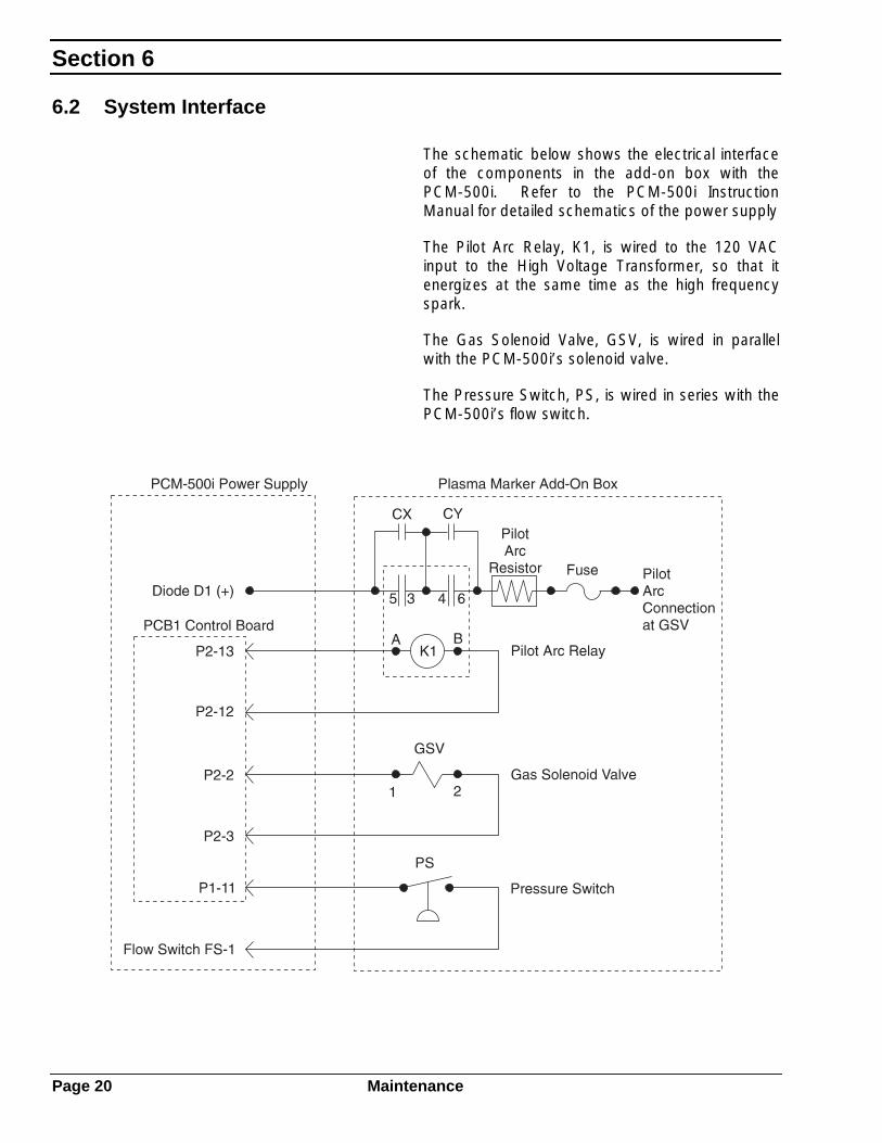
The schematic below shows the electrical interfaceof the components in the add-on box with thePCM-500i. Refer to the PCM-500i InstructionManual for detailed schematics of the power supply
The Pilot Arc Relay, K1, is wired to the 120 VACinput to the High Voltage Transformer, so that itenergizes at the same time as the high frequencyspark.
The Gas Solenoid Valve, GSV, is wired in parallelwith the PCM-500i’s solenoid valve.
The Pressure Switch, PS, is wired in series with thePCM-500i’s flow switch.
EtchArc Plasma Marker
Maintenance Page 21
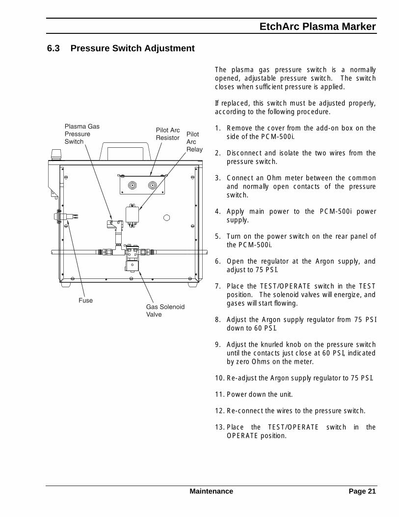
6.3 Pressure Switch Adjustment
The plasma gas pressure switch is a normallyopened, adjustable pressure switch. The switchcloses when sufficient pressure is applied.
If replaced, this switch must be adjusted properly,according to the following procedure.
1. Remove the cover from the add-on box on theside of the PCM-500i.
2. Disconnect and isolate the two wires from thepressure switch.
3. Connect an Ohm meter between the commonand normally open contacts of the pressureswitch.
4. Apply main power to the PCM-500i powersupply.
5. Turn on the power switch on the rear panel ofthe PCM-500i.
6. Open the regulator at the Argon supply, andadjust to 75 PSI.
7. Place the TEST/OPERATE switch in the TESTposition. The solenoid valves will energize, andgases will start flowing.
8. Adjust the Argon supply regulator from 75 PSIdown to 60 PSI.
9. Adjust the knurled knob on the pressure switchuntil the contacts just close at 60 PSI, indicatedby zero Ohms on the meter.
10. Re-adjust the Argon supply regulator to 75 PSI.
11. Power down the unit.
12. Re-connect the wires to the pressure switch.
13. Place the TEST/OPERATE switch in theOPERATE position.

Section 7
Page 22 Replacement Parts
7 Replacement Parts
7.1 General Information
This section provides replacement parts informationand will assist the service/repair person whenperforming maintenance on the system.
The four column parts list for each figure isarranged to show the assembly relationship of partsand subassemblies. Information given in each ofthese columns is as follows:
Column 1, ITEM: Lists each index number foundon the illustration. When no index number is givenfor a part or assembly, it is not illustrated separatelyin the illustration, but its name and descriptionprovide identification.
Column 2, PART #: Gives the ESAB part numberof the part or assembly to which the index numberhas been assigned. Common hardware items orother parts readily available for commercial sourceshave not been included. Parts purchased by ESABfrom vendors are listed by ESAB part numbers.Hardware is specified as items in our parts lists butit normally carries no ESAB part number.
Column 3, QUANTITY: Indicates the quantity ofthat part used in that assembly. This quantitynumber is not to be used as a recommendedquantity of spare parts. The customer mustdetermined how many parts are to be purchasedas spare parts.
Column 4, DESCRIPTION: Gives the name of thepart or assembly, as well as other information whichwill be helpful in identifying it.

EtchArc Plasma Marker
Replacement Parts Page 23
7.2 Ordering Information
When ordering replacement parts, order by partnumber and complete description of the part asgiven in the description column of the list. Inaddition, give the model number of the machineand the machine serial number. Address allinquiries to your local ESAB Distributor or to ESABCutting Systems, P.O. Box 100545, Florence,South Carolina, 29501.
This manual may contain illustrations of parts notapplicable to your specific system. Be sure topositively identify the correct assembly beforeordering replacement parts to avoid unnecessarydelays.
Section 7
Page 24 Replacement Parts
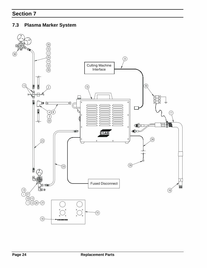
7.3 Plasma Marker System

EtchArc Plasma Marker
Replacement Parts Page 25
Item Part # Qty Description
1 182W82 3 Street Elbow, 1/4 NPT
2 2011322 Service Inlet Bracket Assembly
3 2059445 1 Reducer Bushing, 1/2 NPTM x 1/4 NPTF
4 2211868 1 Street Tee, 1/2 NPT
8 223837022383712238372223834822383492238373
1 Air Supply Hose, 40 ftAir Supply Hose, 50 ftAir Supply Hose, 60 ftAir Supply Hose, 70 ftAir Supply Hose, 80 ftAir Supply Hose, 90 ft
9 223841622384172239208223920956995745
1 Control Cable Assembly, 30’Control Cable Assembly, 50’Control Cable Assembly, 75’Control Cable Assembly, 90’Control Cable Assembly, 160’
10 347995 2 Nipple, B-A/W x 3/8 Hose
11 39Z93 2 Hose Ferrule
12 461107 2 Street Tee, 1/4 NPT
13 59N86 5 Adaptor, B-A/W x 1/4 NPTM
14 56996723 Regulator Mounting Bracket
15 56996871 1 Plasma Marker Power Supply Assembly
16 56996873 1 Plasma Marker Torch Assembly
17 5699687656996877
1 Torch Lead Assembly, 25 ftTorch Lead Assembly, 50 ftTorch Lead Assembly, 75 ftTorch Lead Assembly, 100 ft
19 56996931 1 “PLASMA MARKER ARGON” Label
20 810N40 2 Hose Nut, B-A/W
21 810N40 1 Hose Nut, B-A/W
22 810Z30 1 Adaptor, B-A/W x 1/4 NPTM
23 833132833133
Hose Assembly, B-A/W x B-A/W, 25’Hose Assembly, B-A/W x B-A/W, 50’
24 996857 1 Nipple, B x .430” Hose
25 90858009 Hose, 3/8 I.D. Nylobraid
26 998342 1 Regulator, R77-150-350
27 999134 1 Regulator, R27-75-034
28 73006503 Copper Wire, 6 AWG
29 2062443 1 Terminal Ring
30 2046968 Terminal Strip

Section 7
Page 26 Replacement Parts
7.4 Marker Power Supply Assembly

EtchArc Plasma Marker
Replacement Parts Page 27
Item Part # Qty Description
1 000685 1 PCM-500i Power Supply, Modified
2 951962 1 Pilot Arc Resistor Assembly
3 13735308 1 Relay, DPDT
4 950249 1 Solenoid Valve
5 56996872 1 Interface Enclosure
6 993991 1 Pressure Switch
7 56996889 1 Phenolic Plate
8 56996930 5.5 ft Rubber Wear Strip
9 7 Screw, 10-32 x .75 pan hd
10 952136 1 Fuse Holder
11 4 Screw, M4-.7x10mm pan hd
12 2 Screw, 6-32 x .5 pan hd
13 2 Screw, 8-32 x .63 pan hd
14 59N86 2 Adaptor, B-Water x 1/4 NPTM
15 A/R Wire, 16 AWG, Blue, 600V
16 564773 A/R Terminal Ring, 16 AWG
17 950907 A/R Terminal, 16 AWG
18 44052550 1 Reducer Bushing, 1/4 NPTM x 1/8 NPTF
19 461107 1 Street Tee, 1/4 NPT
20 56996929 1 Fuse, 10 Amp, 600 VDC, Fast Acting
21 951493 2 Capacitor, .068 mf, 630VDC
22 56996461 1 ESAB Label, 4.5”
23 38039 1 Voltage Divider PC Board

Section 7
Page 28 Replacement Parts
7.5 Plasma Marking Torch
Assembly 56996873

EtchArc Plasma Marker
Replacement Parts Page 29
Item Part # Qty Description
1 2237853 1 Torch Body, PM60
2 2237857 1 Marking Electrode
3 2237859 1 Shield Cup
4 56996874 1 Argon/Pilot Arc Adaptor
5 56996875 1 Body-Handle Adaptor
6 569968762237858
Marking Nozzle, .030 OrificeMarking Nozzle, .039 Orifice
7 56996888 1 Air/Power Adaptor
8 853N04 2 Wire Clamp
9 948177 1 Handle Tube
10 90858001 3” Nylon Tube, 1/4 O.D. Black
11 90863005 3” Heat Shrink Tubing
12 2 Screw, M6-1.0x12mm hex soc hd
13 818619 2 Nomex Insulator

Section 7
Page 30 Replacement Parts
7.6 Torch Lead Assembly
25’ Assembly 5699687750’ Assembly 56996878

EtchArc Plasma Marker
Replacement Parts Page 31
Item Part # Qty Description
1 999268999280
1 Air/High Freq. Cable Assy, 25’Air/High Freq. Cable Assy, 50’
2 1845018449
1 Power Cable, 25’Power Cable, 50’
3 72020003 A/R Tubular Metal Braid
4 995832995826
1 Sleeving, 25’Sleeving, 50’
5 73006899 10 ft Copper Cable, #8
6 8996565 1 Hose Clamp
7 56996932 1 Adaptor Ring

F 14 - 109 2/97 Printed in U.S.A.


