PLASMA FOR WATER TREATMENT Mirosław Dors Part-financed by the European Union (European Regional Development Fund) Centre for Plasma and Laser Engineering The Szewalski Institute of Fluid-Flow Machinery Polish Academy of Sciences Gdaosk, Poland 9.00 – 10.30 11.00 – 12.30
Transcript
PLASMA FOR WATER TREATMENT
Mirosław Dors
Part-financed by the European Union(European Regional Development Fund)
Centre for Plasma and Laser EngineeringThe Szewalski Institute of Fluid-Flow Machinery
Polish Academy of SciencesGdaosk, Poland
9.00 – 10.3011.00 – 12.30
Outline
• Plasma technologies for water cleaning
– Plasma sources for water treatment
• Types of electrical discharges used for water treatment
– Discharges in gas
– Discharges in water (electrohydraulic discharges)
• Reactors
• Diagnostics
– Physics of electrohydraulic discharges
• Plasma processes in water cleaning technologies
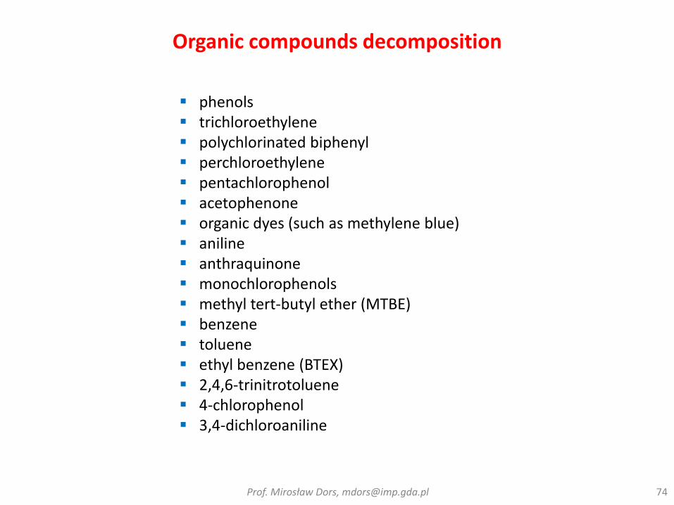
– Plasma processes and plasma-induced processes in destruction of organic compounds and microorganisms
• Chemical reactions
• Biocidal effects
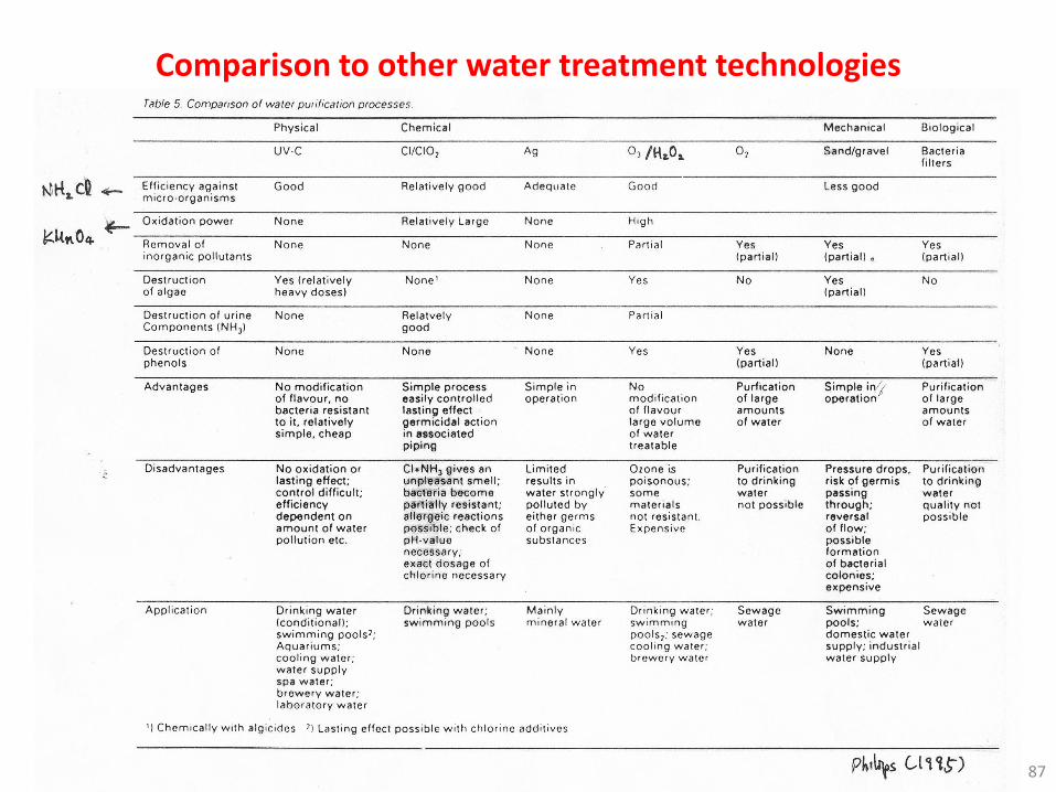
• Comparison to other water treatment technologies
The reason why the breakdown mechanism in liquids is more complicated than solids and gases is evident:
Liquids are much denser in comparison with gases and do not exhibit the long range order as in most solids.
Additionally, the purity of the liquid, such as dissolved gases which form micro-bubbles in the liquid, plays a significant role in the breakdown process.
0a0
2
0p
R
L
E
TDCV
V – breakdown voltageD – thermal diffusivity of water (ca. 1.5e-7 m2/s)Cpρ – specific heat per unit volumeT0 – temperatureσ0 – water conductivityEa – Arrhenius activation energy for the water conductivityL – breakdown channel lengthR0 – breakdown channel radius
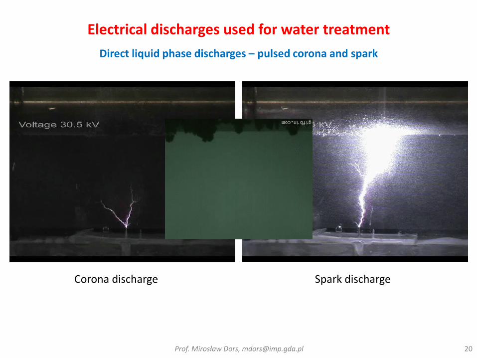
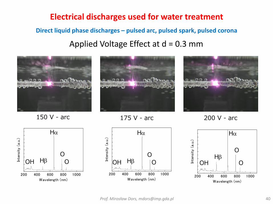
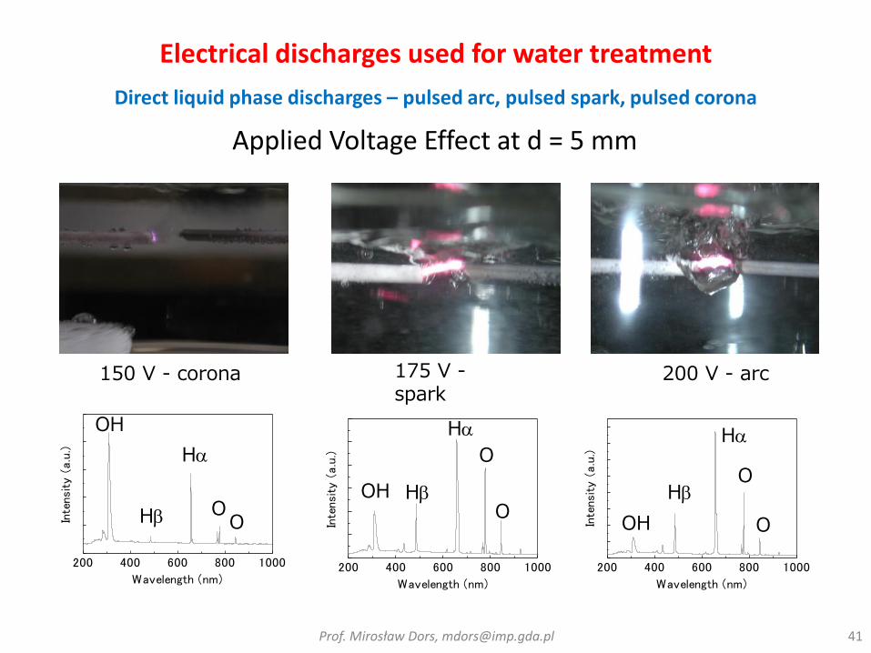
Electrical discharges used for water treatment
Direct liquid phase discharges – pulsed corona and spark
A typical order of magnitude of the local electrical breakdown field of water is 1 MVcm−1 (in the case of microsecond pulsed breakdown), which is more than 30 times the breakdown electrical field of atmospheric pressure air.
For large pulse widths (i.e. several microseconds to dc), especially in high conductive water solutions, the process of breakdown is preceded by vapour formation due to heating by the pre-breakdown current in the liquid.
The first favours an electron multiplication theory in the liquid - In the past, it was often believed that a current multiplication mechanism such as the development of electron avalanches in gas discharges to initiate breakdown. It is interesting to note that electron avalanches have been observed in cyclohexane. Even more direct correlation between these avalanches and the consequent formation of vapour bubbles in the liquid has been demonstrated. However, electron avalanche processes in bulkwater are nearly negligible due to the usual small high electrical field region near the metal electrode and the large scattering cross sections which make it almost impossible for the electrons to gain sufficient kinetic energy for impact ionization. Additionally, free electrons are generally absent in water because even if they are present, they are quickly solvated within 1 ps time scales. Hence, the probability of free electrons in the bulk water is negligible, although one must be careful not to generalize ideas for different liquids and not to exclude electron avalanche processes without a good motivation.
The second school favours a bubble mechanism breakdown theory or more generally a phase change mechanism breakdown theory - a general acceptance is growing that pre-existing bubbles and field enhancement effects in the near electrode region are involved even for nanoseconds voltage pulse widths. Bubbles can pre-exist due to dissolved gases or can be generated by local heating (energy injection from the electrode by pre-breakdown currents) and cavitation.
Electrical discharges used for water treatment
Direct liquid phase discharges – pulsed corona and spark
Electrical breakdown is generally defined as the moment when a conductive plasma channel forms an electrical connection between the two metal electrodes inside the liquid. This leads to the formation of a spark or arc. A time lag between application of the high voltage and breakdown is always observed.
This time lag consists of three successive steps: • initiation phase or streamer inception, • streamer propagation phase,• spark and arc phase.
Different streamer modes are observed depending on polarity of the powered electrode and the pulse width and amplitude of the applied voltage pulse.
At first a bushlike hemispherical primary streamer (PS) can be observed showing 100–200 filaments.
Then, a fast secondary streamer (SS) appears above a certain threshold voltage (which depends on the geometry of the setup) and can be considerably longer.
1. Primary streamer (subsonic streamer):• low electron density, • low temperature,• low pressure.• its propagation mechanism: series of current pulses and electron avalanches
in successive vapour bubbles,• appear at low amplitude voltage pulses often filling a hemisphere with a size
of a few hundred micrometres (at least for positive streamers) or have a bush-like shape (negative streamers have many short side branches and are shorter in length than positive streamers. Bubble production during the discharge is also much lower for negative voltages than for positive ones under the same conditions).
2. Secondary streamer:• high electron density,• high temperature,• high pressure,• its propagation mechanism: field induced dissociation and ionization of
molecules in the bulk liquid, • propagation velocity in the range 10–100 km s−1.
Zoom on the current waveform, (0) beginning of the applied voltage pulse, (1) initiation (or pre-initiation) current due to conductivity of water ∼300mA here, (2) current ramp of the plasma primary positive streamer ∼50 mA, (3) current increase of the secondary positive streamer ∼1A, (4) reilluminations (7μS cm−1, 40 kV)
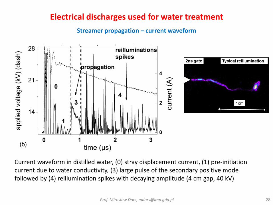
Current waveform in distilled water, (0) stray displacement current, (1) pre-initiation current due to water conductivity, (3) large pulse of the secondary positive mode followed by (4) reillumination spikes with decaying amplitude (4 cm gap, 40 kV)
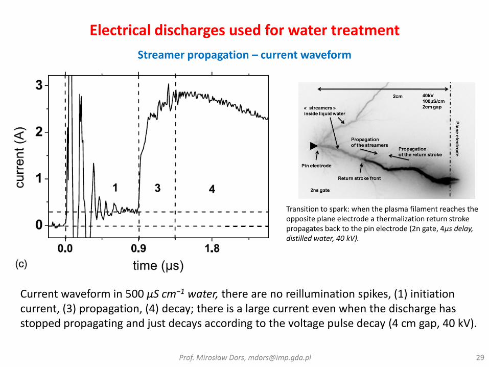
Current waveform in 500 μS cm−1 water, there are no reillumination spikes, (1) initiation current, (3) propagation, (4) decay; there is a large current even when the discharge has stopped propagating and just decays according to the voltage pulse decay (4 cm gap, 40 kV).
Streamer propagation – current waveform
Transition to spark: when the plasma filament reaches the opposite plane electrode a thermalization return stroke propagates back to the pin electrode (2n gate, 4μs delay, distilled water, 40 kV).
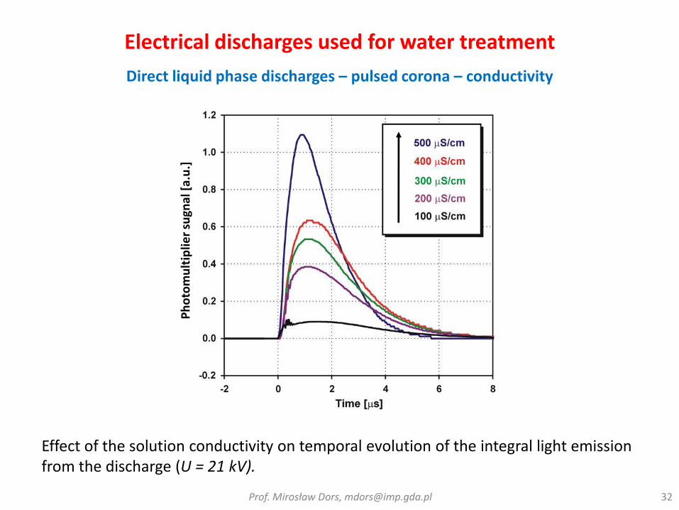
Electrical discharges used for water treatment
Direct liquid phase discharges – pulsed corona – conductivity
Role of ceramics: increasing the electrical field strength on the anode wire surface due to the redistribution of the field inside the interelectrode space during the prebreakdown stage, thus generating a larger number of discharge channels per pulse.
20 kV
Electrical discharges used for water treatment
Direct liquid phase discharges – pulsed corona – wire-to-plate
• 240 to 280 nm - damaging nucleic acids of microorganisms
(Tchobanoglous, 1997)
HOWEVER,
Under certain conditions, some organisms are capable of repairingdamaged DNA and reverting back to an active state in which reproduction is again possible – “Dark repair mechanisms”
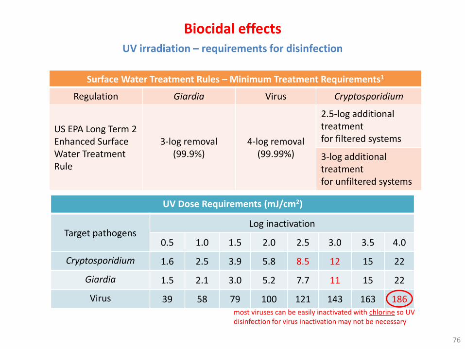
UV irradiation – requirements for disinfection
Surface Water Treatment Rules – Minimum Treatment Requirements1
Regulation Giardia Virus Cryptosporidium
US EPA Long Term 2 Enhanced Surface Water Treatment Rule
3-log removal (99.9%)
4-log removal (99.99%)
2.5-log additional treatmentfor filtered systems
3-log additional treatmentfor unfiltered systems
UV Dose Requirements (mJ/cm2)
Target pathogensLog inactivation
0.5 1.0 1.5 2.0 2.5 3.0 3.5 4.0
Cryptosporidium 1.6 2.5 3.9 5.8 8.5 12 15 22
Giardia 1.5 2.1 3.0 5.2 7.7 11 15 22
Virus 39 58 79 100 121 143 163 186most viruses can be easily inactivated with chlorine so UV disinfection for virus inactivation may not be necessary
• destruction of bacterial membrane through alteration of:- glycoproteins or glycolipids (Scott and Lesher, 1963)- certain amino acids such as tryptophan (Goldstein and McDonagh, 1975)
• disruption of enzymatic activity of bacteria by acting on the sulfhydryl groups of certain enzymes (Giese and Christensen, 1954)
• affection of both purines and pyrimidines in nucleic acids (Scott and Lesher, 1963)
Bacteria
Virus
• modification of the viral capsid sites that the virion uses to fix on the cell surfaces. High concentrations of ozone dissociate the capsid completely (Cronholm et al., 1976 and Riesser et al., 1976)
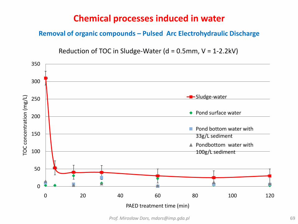
•V = 4kV•PAED: 5 sec/pulse, 100 pulse = 9min•Accumulative energy for 100pulses for high conductivity water = 2.8 kWh/m3•Accumulative energy for 100, 300, 400, 500 pulses for low conductivity water = 6.3, 19, 25.3 and 31.6 kWh/m3
•V = 4kV•PAED: 5 sec/pulse, 100 pulse = 9min•Accumulative energy for 100pulses for high conductivity water = 2.8 kWh/m3•Accumulative energy for 100, 300, 400, 500 pulses for low conductivity water = 6.3, 19, 25.3 and 31.6 kWh/m3
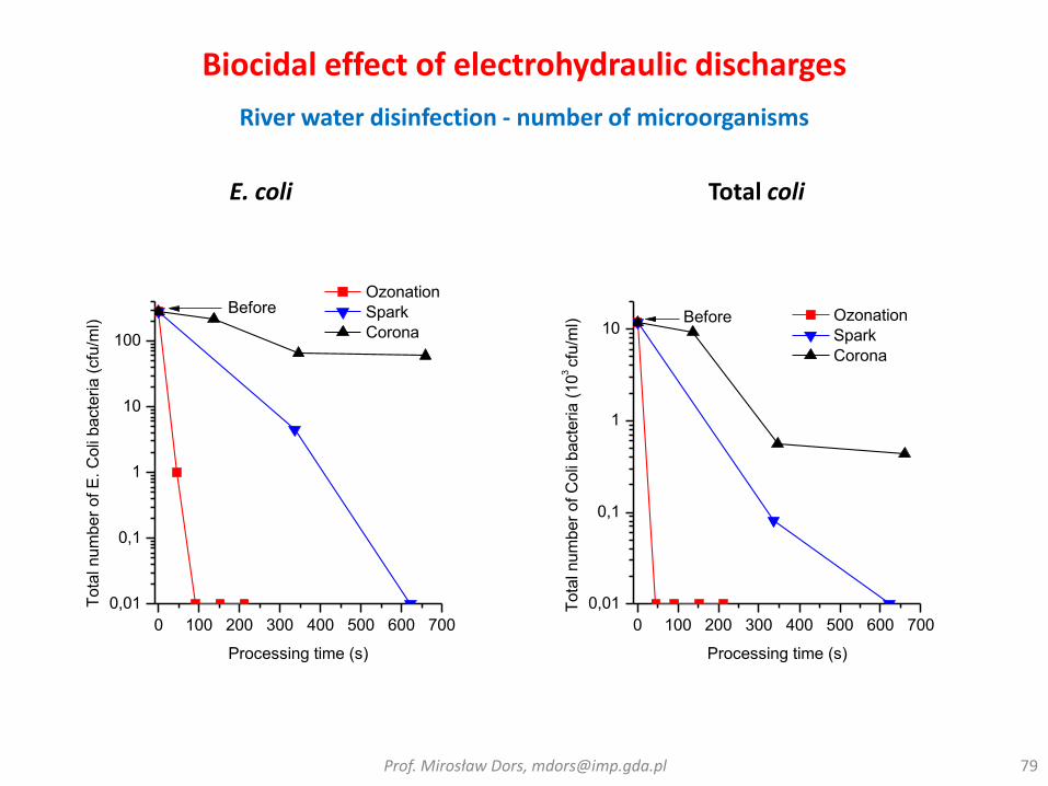
Biocidal effect of electrohydraulic discharges
Pulsed arc in the sea water – removal of algae and mussels
Regional Municipality of Waterloo’s Mannheim Drinking Water Treatment Plant, Canada – Pulsed arc discharge in water ● 50 L/s● E. coli● B. subtilis● Natural Organic Matter● MTBE
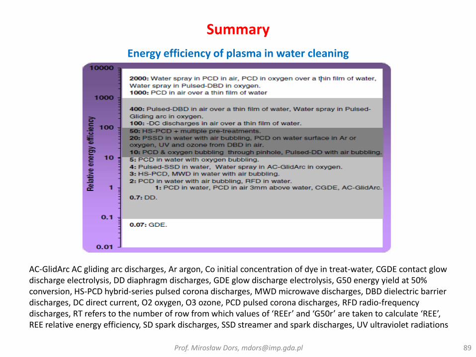
AC-GlidArc AC gliding arc discharges, Ar argon, Co initial concentration of dye in treat-water, CGDE contact glow discharge electrolysis, DD diaphragm discharges, GDE glow discharge electrolysis, G50 energy yield at 50% conversion, HS-PCD hybrid-series pulsed corona discharges, MWD microwave discharges, DBD dielectric barrier discharges, DC direct current, O2 oxygen, O3 ozone, PCD pulsed corona discharges, RFD radio-frequency discharges, RT refers to the number of row from which values of ‘REEr’ and ‘G50r’ are taken to calculate ‘REE’, REE relative energy efficiency, SD spark discharges, SSD streamer and spark discharges, UV ultraviolet radiations
References• Locke B R, Sato M, Sunka P, Hoffmann M R and Chang J S, 2006 , Electrohydraulic discharge and nonthermal plasma, for
water treatment Indust. Eng. Chem. Res. 45 882–905
• Malik M A, Ghaffar A and Malik S A 2001 Water, purification by electrical discharges Plasma Sources Sci., Technol. 10 82–91
• An W, Baumung K and Bluhm H 2007 Underwater streamer propagation analyzed from detailed measurements of pressure release J. Appl. Phys. 101 053302
• Sato K and Yasuoka K 2008 Pulsed discharge development in oxygen, argon, and helium bubbles in water IEEE Trans. Plasma Sci. 36 1144–5
• Sunka P, Babicky V, Clupek M, Lukes P, Simek M, Schmidt J and Cernak M 1999 Generation of chemically active species by electrical discharges in water Plasma Sources Sci. Technol. 8 258–65
• J. S. Chang, “Thermal Plasma Solid Waste and Water Treatments: A Critical Review,” Int. J. Plasma Env. Sci. Techn., vol. 3, no. 2, 2009
• Lukes P and Locke B R 2005 Plasmachemical oxidation processes in a hybrid gas–liquid electrical discharge reactor J. Phys. D: Appl. Phys. 38 4074–81
• P H Ceccato, O Guaitella, M Rabec Le Gloahec and A Rousseau, Time-resolved nanosecond imaging of the propagation of a corona-like plasma discharge in water at positive applied voltage polarity, J. Phys. D: Appl. Phys., 43 (2010) 175202
• A.A. Joshi, B.R. Locke, P. Arce, W.C. Finney, ”Formation of hydroxyl radicals, hydrogen peroxide and aqueous electrons by pulsed streamer corona discharge in aqueous solution”, Journal of Hazardous Materials, vol. 41, pp. 3-30, 1995
• N. Karpel Vel Leitner, G. Syoen, H. Romat, K. Urashima, J.-S. Chang, Generation of active entities by the pulsed arc electrohydraulic discharge system and application to removal of atrazine, Water Research 39 (2005) 4705–4714
• Sugiarto, A. T.; Sato, M. Pulsed plasma processing of organic compounds in aqueous solution. Thin Solid Films 2001, 386, 295
• A. Abou-Ghazala, S. Katsuki, Karl H. Schoenbach, F. C. Dobbs, and K. R. Moreira, Bacterial Decontamination of Water byMeans of Pulsed-Corona Discharges, IEEE Trans. Plasma Sci. , 30 (2002) 4, 1449-1453
• M. Dors, J. Mizeraczyk, Y.S. Mok, Phenol Oxidation in Aqueous Solution by Gas Phase Corona Discharge, Journal of AdvancedOxidation Technologies, 9, 139-143, 2006
• M. Dors, E. Metel, J. Mizeraczyk, Phenol Degradation in Water by Pulsed Streamer Corona Discharge and Fenton Reaction, Int. J. Plasma Environ. Sci. Technol., 1, 76-81, 2007
• M. Dors, E. Metel, J. Mizeraczyk, E. Marotta, Coli bacteria inactivation by pulsed corona discharge in water, Int. J. Plasma Environ. Sci. Technol., 2, 34-37, 2008
• Fridman A., Plasma Chemistry, Cambridge University Press, 2008Prof. Mirosław Dors, [email protected] 91