P HILOSOPHICAL MAGAZINE B, 1999, VOL. 79, NO. 10, 1531± 1548 Plasmon excitations in carbon nanotubes T homas S to ï ckli { k , Z hong L inW ang{,J ean - M arc B onard{, P ierre S tadelmann }, and Andre í C ha î telain { y Institut de Physique ExpeÂrimentale, DeÂpartement de Physique, Ecole Polytechnique FeÂdeÂrale de Lausanne, CH-1015 Lausanne, Switzerland { School of Materials Science and Engineering, Georgia Institute of Technology, Atlanta, Georgia 30332-0245, USA } Centre Interde partemental de Microscopie Electronique, Ecole Polytechnique FeÂdeÂrale de Lausanne, CH-1015 Lausanne, Switzerland [ Received 16 November 1998 and accepted 29 April 1999] Abstract Electron-energy-loss spectroscopy (EELS) in a high-resolution transmission electron microscope can be used to study the excitation of plasmons in nanometre-size particles with high spatial resolution. For isotropic particles of various shapes, models which allow the attribution of the experimental peaks to a certain excitation mechanism and to understand size- or geometry-dependent variations are well established. Recently, locally anisotropic particles such as nested concentric-shell fullerenes and carbon nanotubes have been discovered and have attracted considerable interest. The plasmon losses of these anisotropic particles measured by EELS could contribute to a better understanding of their physical properties, once the theoretical basis for the interpretation is adapted for anisotropic particles. Encouraged by very good qualitative agreement between a model of the plasmons of nested concentric- shell fullerenes based on non-relativistic local dielectric response theory with experimental data, we present here a model for the plasmon excitations of multiwall carbon nanotubes based on the same theoretical approach. } 1. Introduction Multiwall carbon nanostructures consist of several graphene sheets rolled up into cylinders (Iijima 1991, Ebbesen and Ajayan 1992) or spheres (Ugarte 1992) (® gure 1) which are arranged coaxially or concentrically and belong to what are commonly called carbon nanostructures. C 60 fullerenes were the ® rst of these structures to be discovered (Kroto et al. 1985). When it became possible to produce them in macro- scopic quantities and in crystalline form (KraÈ tscher et al. 1990), it was found that they had remarkable physical properties. Unlike crystalline graphite which is semi- metallic, or diamond which is insulating, the C 60 crystals were semiconducting with a well de® ned gap. When multiwall graphitic tubular structures were discovered (Iijima 1991, Ebbesen and Ajayan 1992) the question about their properties was immediate. At ® rst, simulations of the electronic properties of single-wall tubular structures (single- wall carbon nanotubes) suggested that the electronic properties should strongly Philosophical Magazine B ISSN 0141± 8637 print/ISSN 1463± 6417 online # 1999 Taylor & Francis Ltd http://www.tandf.co.uk/JNLS/phb.htm http://www.taylorandfrancis.com/JNLS/phb.htm k Email: [email protected].
Thomas Stoïckli{k , Zhong LinWang{, Jean-Marc Bonard{,Pierre Stadelmann}, and Andreí Chaîtelain{
y Institut de Physique Expe rimentale, De partement de Physique, EcolePolytechnique Fe de rale de Lausanne, CH-1015 Lausanne, Switzerland
{ School of Materials Science and Engineering, Georgia Institute of Technology,Atlanta, Georgia 30332-0245, USA
} Centre Interde partemental de Microscopie Electronique, Ecole PolytechniqueFe de rale de Lausanne, CH-1015 Lausanne, Switzerland
[Received 16 November 1998 and accepted 29 April 1999]
AbstractElectron-energy-loss spectroscopy (EELS) in a high-resolution transmission
electron microscope can be used to study the excitation of plasmons innanometre-size particles with high spatial resolution. For isotropic particles ofvarious shapes, models which allow the attribution of the experimental peaks to acertain excitation mechanism and to understand size- or geometry-dependentvariations are well established. Recently, locally anisotropic particles such asnested concentric-shell fullerenes and carbon nanotubes have been discoveredand have attracted considerable interest. The plasmon losses of theseanisotropic particles measured by EELS could contribute to a betterunderstanding of their physical properties, once the theoretical basis for theinterpretation is adapted for anisotropic particles. Encouraged by very goodqualitative agreement between a model of the plasmons of nested concentric-shell fullerenes based on non-relativistic local dielectric response theory withexperimental data, we present here a model for the plasmon excitations ofmultiwall carbon nanotubes based on the same theoretical approach.
} 1. IntroductionMultiwall carbon nanostructures consist of several graphene sheets rolled up into
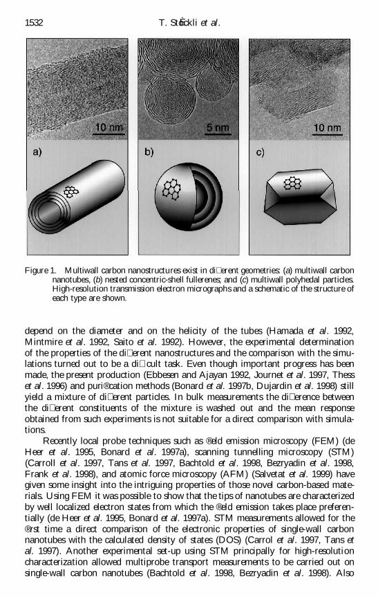
cylinders (Iijima 1991, Ebbesen and Ajayan 1992) or spheres (Ugarte 1992) (® gure 1)which are arranged coaxially or concentrically and belong to what are commonlycalled carbon nanostructures. C60 fullerenes were the ® rst of these structures to bediscovered (Kroto et al. 1985). When it became possible to produce them in macro-scopic quantities and in crystalline form (KraÈ tscher et al. 1990), it was found thatthey had remarkable physical properties. Unlike crystalline graphite which is semi-metallic, or diamond which is insulating, the C60 crystals were semiconducting with awell de® ned gap.
When multiwall graphitic tubular structures were discovered (Iijima 1991,Ebbesen and Ajayan 1992) the question about their properties was immediate. At® rst, simulations of the electronic properties of single-wall tubular structures (single-wall carbon nanotubes) suggested that the electronic properties should strongly
Philosophical Magazine B ISSN 0141± 8637 print/ISSN 1463± 6417 online # 1999 Taylor & Francis Ltdhttp://www.tandf.co.uk/JNLS/phb.htm
depend on the diameter and on the helicity of the tubes (Hamada et al. 1992,Mintmire et al. 1992, Saito et al. 1992). However, the experimental determinationof the properties of the di� erent nanostructures and the comparison with the simu-lations turned out to be a di� cult task. Even though important progress has beenmade, the present production (Ebbesen and Ajayan 1992, Journet et al. 1997, Thesset al. 1996) and puri® cation methods (Bonard et al. 1997b, Dujardin et al. 1998) stillyield a mixture of di� erent particles. In bulk measurements the di� erence betweenthe di� erent constituents of the mixture is washed out and the mean responseobtained from such experiments is not suitable for a direct comparison with simula-tions.
Recently local probe techniques such as ® eld emission microscopy (FEM) (deHeer et al. 1995, Bonard et al. 1997a), scanning tunnelling microscopy (STM)(Carroll et al. 1997, Tans et al. 1997, Bachtold et al. 1998, Bezryadin et al. 1998,Frank et al. 1998), and atomic force microscopy (AFM) (Salvetat et al. 1999) havegiven some insight into the intriguing properties of those novel carbon-based mate-rials. Using FEM it was possible to show that the tips of nanotubes are characterizedby well localized electron states from which the ® eld emission takes place preferen-tially (de Heer et al. 1995, Bonard et al. 1997a). STM measurements allowed for the® rst time a direct comparison of the electronic properties of single-wall carbonnanotubes with the calculated density of states (DOS) (Carrol et al. 1997, Tans etal. 1997). Another experimental set-up using STM principally for high-resolutioncharacterization allowed multiprobe transport measurements to be carried out onsingle-wall carbon nanotubes (Bachtold et al. 1998, Bezryadin et al. 1998). Also
1532 T. StoÈ ckli et al.
Figure 1. Multiwall carbon nanostructures exist in di� erent geometries: (a) multiwall carbonnanotubes, (b) nested concentric-shell fullerenes; and (c) multiwall polyhedal particles.High-resolution transmission electron micrographs and a schematic of the structure ofeach type are shown.
using the set-up of STM, the conductivity of multiwall carbon nanotubes has beendetermined. It appears to be quantized, hinting that the transport in these structuresmay be ballistic even at room temperature (Frank et al. 1998). Finally, AFMmeasurements revealed that both single-wall and multiwall tubular structures areextremely sti� (Salvetat et al. 1999).
Another technique giving complementary information about the electronic prop-erties of nanometre-size particles is electron-energy-loss spectroscopy (EELS) in ahigh-resolution transmission electron microscope. Di� erent experimental studiesusing this technique have been carried out on carbon nanostuctures (Ajayan et al.1992, Bursill et al. 1992, Kuzuo et al. 1992, Ste phan et al. 1996, Yase et al. 1996,StoÈ ckli et al. 1997a). For the plasmon region, however no detailed interpretation ofthe experimental data is available. The reason for this is that, even though muchtheoretical work on carbon nanostructures has already been done, the excitation ofplasmons by high-energy electrons has not been addressed in detail except in a recentpublication where we have given the basis for the interpretation of electron-energy-loss spectra of nested concentric-shell fullerenes (StoÈ ckli et al. 1998a) . Using the sameapproach, based on non-relativistic local dielectric response theory (for a review, seeWang (1996)), we present here the theoretical basis for the interpretation of EELSexperiments on multiwall carbon nanotubes, taking into account their particularanisotropy.
Non-relativistic local dielectric response theory has been used with success forthe interpretation on isotropic nanometre-size particles of di� erent geometries suchas thin slabs (Ritchie 1957), spheres (Ferrel and Echenique 1985, Bausells et al. 1987,Echenique et al. 1987, Ferrell et al. 1987), layered spheres (Ferrell et al. 1987, Ugarteet al. 1992, StoÈ ckli et al. 1997b), spheres halfway embedded in a supporting medium(Wang and Cowley 1987, Zabala and Rivacoba 1991), and cylindrical channels (Chuet al. 1984, Zabala et al. 1989, Walsh 1991, Rivacoba et al. 1995). Since a preliminarycomparison of experimental data with the simulations of the anisotropic spheres(nested concentric-shell fullerenes) shows excellent qualitative agreement betweentheory and measurement (StoÈ ckli et al. 1998b), we are con® dent that the followingresults will give a valuable basis for the interpretation of the electron-energy-lossspectra of multiwall carbon nanotubes for penetrating and non-penetratingelectrons.
} 2. Non-relativistic local dielectric responsetheory of small particles
2.1. General considerationsThe basic idea of non-relativistic local dielectric response theory is to calculate
the energy loss of one single probe electron{ by integration of the elementary work¯W ˆ F…x; t†·dx done by the electric ® eld acting on the electron along its trajectory:
E ˆ ¡
…
trajectory¯W ˆ
e
2p
…
trajectory
… 1
¡ 1exp …¡ i! t† E…x; !† d! ·dx: …1†
Plasmon excitations in carbon nanotubes 1533
{ In a transmission electron microscope an electron flux of about 1012 electrons s¡ 1 passesthrough the sample. However, the electrons have a rather high kinetic energy (typically100 keV and more) and their speed is of the order of half the speed of light. As a consequence,the distance between successive electrons is large enough that the interaction between them canbe neglected.
It is assumed that the electron is travelling on a straight line and at constant velocityv{ so that the evaluation of the path integral is possible.
The electric ® eld needed for the evaluation of the energy loss E is determinedusing the Maxwell equations. Within this formalism, the medium through which theelectron is travelling is characterized by its frequency-dependent complex dielectrictensor{ . This requires the resolution of the Maxwell equations in frequency space sothat the electric ® eld is obtained as frequency-dependent function. However, for thedetermination of the energy which the electron loses when passing through thesample (equation (1)) the time-dependent electric ® eld needs to be known. In equa-tion (1) the electric ® eld is therefore written as the Fourier transform of the fre-quency-dependent dielectric response as obtained from the resolution of the Maxwellequations into time space. For the Fourier transform, the following convention hasbeen adapted:
A…r; !† ˆ
… 1
¡ 1exp …i!t† A…r; t† dt …2 a†
is the direct Fourier transform from time space into frequency space, and
A…r; t† ˆ12p
… 1
¡ 1exp …¡ i!t† A…r; !† d! …2 b†
is the inverse transform from frequency into time space.It has to be noted that the energy lost by the electron upon interaction with the
sample can also be expressed in terms of the plasmon excitation probabilitydP …!†=d! :
E ˆ
… 1
0!
dP …!†d!
d!: …3†
Eliminating E in equations (1) and (3) the probability dP …!†=d! for an electron tolose the amount of energy ! can be calculated. This quantity is of considerableinterest since it can be compared directly with experimental data.
For the determination of the energy loss (equation (1)) an additional simpli® ca-tion of the original problem is introduced; it is assumed that the probe electroninstantaneously reacts with the ® eld which it induces}. For particles with isotropicelectronic properties, the Maxwell equations in this case lead to the Poisson equation
r2V …r; !† ˆ ¡
1"0"…!†
»…r; !†: …4 a†
For the case when the particle has anisotropic dielectric properties the equationwhich determines the potential is given by
1534 T. StoÈ ckli et al.
{ The energy loss of the probe electrons in the plasmon region is below 40 eV. Comparedwith the primary energy of more than 100 keV, this energy is negligible. Scattering angles ofelectrons exciting plasmons in the sample are smaller than about 50 mrad. In consequence, thetrajectory of the probe electrons is in good approximation a straight line.
{ It can be realized that the wave-vector dependence of the dielectric response of themedium is excluded (local response). Even with this simplification, the model has provedsuccessful in explaining the plasmon losses of small particles of various geometries.
} It is assumed that the terms in …v=c†2 are small compared with the other terms in theMaxwell equations (non-relativistic theory). This means that retardation effects and CÏ erenkovradiation are neglected.
Ñ · "0~"…!† Ñ V …r; !†‰ Š ˆ ¡ »…r; !†: …4 b†
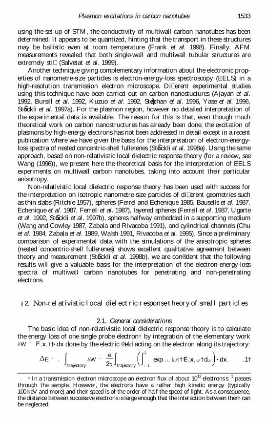
»…r; !† is the Fourier transform of the point charge located at position r and, for thegeometry shown in ® gure 2, is given by
»…r; !† ˆ¡ e
v¯…x ¡ x 0†¯…z† exp
i!y
v: …5†
From the viewpoint of classical electrodynamics, the probe electron can interact intwo ways with nanometre-size particles. On the one hand it can polarize the mediumin which it travels. This polarization requires energy and the corresponding energyloss of the probe electrons can be observed in the electron-energy-loss spectra. Thelosses due to this excitation mechanism are called volume plasmons. The position ofthe maxima of the volume plasmon excitation (resonance) are determined by thezeros of the real part of the dielectric function. On the other hand the probe electroncan induce surface charges. They enter in resonance at a frequency which is deter-mined by the position of the volume plasmon resonance and the geometry of theparticle. The losses due to this excitation mechanism are called surface plasmons andcan only be observed when the particles are small enough.
2.2. Surface plasmon excitationBasically, equations (1) and (3) allow the total plasmon excitation probability to
be determined using the solution of equations (4 a) and (4 b). However, it is con-venient to treat the surface and volume plasmon excitations separately. For thispurpose it can be noted that the general solution of equations (4a) and (4 b) is thesum of the homogeneous and the particular solution of the problem. The two termsrepresent the induced potential (surface plasmon) and the direct potential (volumeplasmon) respectively:
V …r; !† ˆ Vind…r; !† ‡ V
p…r; !†: …6†
Since the induced potential responsible for the surface losses can be calculatedseparately, it is useful to introduce the notion of surface plasmon excitation prob-
Plasmon excitations in carbon nanotubes 1535
Figure 2. Geometrical de® nitions for the carbon nanotube geometry. The electron, located atposition r0, is travelling at constant velocity at an impact-parameter x0 from the originin negative y-direction. In cylindrical coordinates, its position is given by the para-meters r0, ’0 and z0.
ability dPsurf …!†=d!: Starting from equations (1) and (3) it can be shown that the
surface excitation probability for the geometry shown in ® gure 2 is given by thefollowing expression (Wang 1996){ ;
dPsurf …!†d!
ˆe
p v2
… 1
¡ 1dy
0
… 1
¡ 1dy Im exp
i!…y0
¡ y†v
Vind…r; r0† r0ˆ …x 0;y
0;0†
rˆ …x0 ;y;0†
#
:
"
…7†
It is important to note that the time dependence of the problem has been eliminated.V
ind…r; r0† is the induced potential at position r caused by a stationary electronlocated at position r0. It is the homogeneous part of the solution of
r2V …r; r0† ˆ
e
"0"…!†¯…r ¡ r0† …8†
if the electron is travelling in an isotropic medium and of
Ñ · ~"…!† Ñ V …r; r0†‰ Š ˆe
"0¯…r ¡ r0† …9†
if it is in an anisotropic medium. The potential distribution therefore is quasi-elec-trostatic and frequency dependent for each point along the trajectory of the incidentelectron. The integral over y is the sum over the contributions of all the points alongthe trajectory.
2.3. V olume plasmon excitationThe volume plasmon excitation in a uniaxial crystal such as graphite has
been treated theoretically by di� erent workers (Hubbard 1955a,b, Tosatti 1969,Wessjohann 1974, Daniels et al. 1979). Probably the most detailed calculationshave been published by Wessjohann (1974). For a uniaxial crystal with its c axisinclined by an angle ¬ with respect to the optical axes of the microscope (® gure 3) thevolume plasmon excitation probability per unit path length is given by
d2P
volume…!†d! dy
ˆe
2
4p3v2"0
… ³c
0³ d³
… 2p
0d’ Im
¡ q20
q2p"? …!† ‡ q2
c"k …!†… † …10†
qc and qp are the projection of the transferred momentum q on to the coordinatesystem in which the dielectric tensor is diagonal, that is on the unit vector parallel tothe c axis of graphite and on to the plane perpendicular to the c axis respectively(® gure 3). The two projections can be expressed in terms of the scattering angle ³, theazimuthal angle ’ and the angle ¬ between the c axis of the crystal and the opticalaxis (® gure 3):
q2p ˆ q
20‰…³E sin ¬ ¡ ³ cos ’ cos ¬†2 ‡ ³ sin ’†… 2Š …11 a†
q2c ˆ q
20‰³E cos ¬ ¡ ³ cos ’ sin ¬Š2; …11 b†
where ³E is given by
³E ˆ!
2pvq0: …12†
1536 T. StoÈ ckli et al.
{ Because in our case the electron is assumed to move in the opposite direction comparedwith that in review by Wang (1996), the sign of the expression in the imaginary part needs tobe plus instead of minus.
The integration over the angles ³ and ’ takes into account all electrons scatteredwithin an angle smaller than the cut-o� angle ³c (Egerton 1996).
} 3. Modelling the dielectric properties ofa carbon nanotubeMultiwall carbon nanotubes consist of several graphene sheets rolled up to
cylinders of di� erent diameters, embedded coaxially into one another so that thedistance between the layers is approximately equal to the interlayer distance ofplanar graphite (® gure 1). In contrast with nested concentric-shell fullerenes,which are almost always completely ® lled (one can imagine the innermost shell tobe a C60 fullerene) , carbon nanotubes are hollow. This means not only that surfaceplasmons exist on the outer surface but also that there are additional surface modeson the inner surface and coupling modes between the surfaces. For mathematicalconvenience, but also because the plasmons on the inner surface are screened by thebody of the nanotube, we don’ t take into account the inner hollow in the calculationsof the surface plasmon excitation probability{ (} 4). Since the volume plasmon con-tribution is far more important than the surface contribution as long as the tube hasmore than about ® ve layers, it will, however, be important to correct the volumeplasmon excitation probability for the inner hollow (} 5).
Plasmon excitations in carbon nanotubes 1537
Figure 3. Momentum transfer components for a probe electron passing through a uniaxialcrystal. The crystal’ s c axis is tilted by an angle ¬ with respect to the incident electronbeam. Before the scattering event, the electron has a momentum of q0. During thescattering event, it transfers the quantity q to the crystal and leaves deviated by theangle ³ with respect to its incident direction and by the azimuthal angle ’ .
{ The approach presented in this paper is also suitable for calculating the surface modeson the inner surface. In fact it would be sufficient to include an additional boundary betweenthe tube and the inner hollow. The potential could then be calculated exactly in the same wayfor the three different regions.
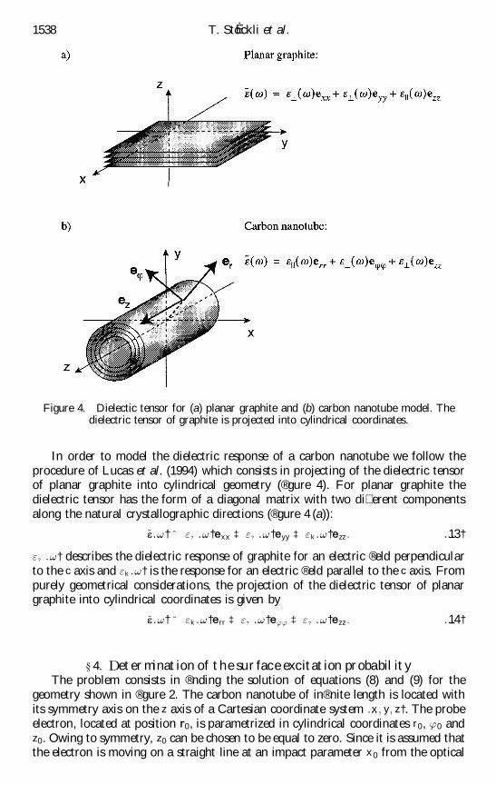
In order to model the dielectric response of a carbon nanotube we follow theprocedure of Lucas et al. (1994) which consists in projecting of the dielectric tensorof planar graphite into cylindrical geometry (® gure 4). For planar graphite thedielectric tensor has the form of a diagonal matrix with two di� erent componentsalong the natural crystallographic directions (® gure 4 (a)):
~e …!† ˆ "? …!†exx ‡ "? …!†eyy ‡ "k …!†ezz : …13†
"? …!† describes the dielectric response of graphite for an electric ® eld perpendicularto the c axis and "k …!† is the response for an electric ® eld parallel to the c axis. Frompurely geometrical considerations, the projection of the dielectric tensor of planargraphite into cylindrical coordinates is given by
~e …!† ˆ "k …!†err ‡ "? …!†e’’ ‡ "? …!†ezz : …14†
} 4. Determinationof the surface excitation probabilityThe problem consists in ® nding the solution of equations (8) and (9) for the
geometry shown in ® gure 2. The carbon nanotube of in® nite length is located withits symmetry axis on the z axis of a Cartesian coordinate system …x ; y; z†. The probeelectron, located at position r0, is parametrized in cylindrical coordinates r0, ’0 andz0. Owing to symmetry, z0 can be chosen to be equal to zero. Since it is assumed thatthe electron is moving on a straight line at an impact parameter x 0 from the optical
1538 T. StoÈ ckli et al.
Figure 4. Dielectic tensor for (a) planar graphite and (b) carbon nanotube model. Thedielectric tensor of graphite is projected into cylindrical coordinates.
axis of the microscope (y axis), r0 and ’0 can be expressed as functions of the impactparameter and y: r0 ˆ …y
2 ‡ x20†1=2 and cos ’0 ˆ x 0=r0.
For the determination of the potential, two cases need to be distinguished,namely the electron located outside and inside the nanotube. The potentials forthe two cases are denoted as V
in…r; r0† and Vout…r; r0† respectively, where r is an
arbitrary position in space and r0 is the electron position (® gure 2).
4.1. Potential distribution for an electron outside the cylinderThe equations that determine the potential distribution for an electron travelling
outside the cylinder are
r2V
outr>a …r; r0† ˆ ¡
1"0
»…r; r0† f or r > a …15 a†
and
Ñ · ~"…!† Ñ Voutr<a …r; r0† ˆ 0 for r < a : …15 b†
»…r; r0† ˆ ¡ e¯…r ¡ r0† represents an electron located at r0 and a is the radius of thecylinder (see ® gure 2).
As discussed in } 2.2, the solution of equation (15 a) is written as the sum of thesolution of the homogeneous problem, V
out indr>a …r; r0† and the solution of the inho-
mogeneous problem, Vout pr>a …r; r0†.
Voutr>a …r; r0† ˆ V
out indr>a …r; r0† ‡ V
out pr>a …r; r0†: …16†
Equation (15 a) with the inhomogeneous term representing a point charge located atr0 is frequently encountered in classical electrodynamics and its particular solution is
Vout pr>a …r; r0† ˆ ¡
e
4p"0jr ¡ r0j: …17†
For our problem, this solution is rewritten as a Fourier Bessel expansion (Jackson1975):
In equation (18 b), ³…x † is the Heaviside step function, de® ned as
³…x † ˆ1 f or x > 00 for x < 0;
…19†
and Km …jqjr† and Im…jqjr† are the modi® ed Bessel functions (Bessel function of purelyimaginary argument (Watson 1996)) of order m and of argument jqjr .
The homogeneous solution of equation (15 a) is also written as a Fourier Besselexpansion with coe� cients Am…q; !† that are determined by the boundary conditions:
Plasmon excitations in carbon nanotubes 1539
Vout indr>a …r; r0† ˆ ¡
e
2p"0
X
m 5 0
…2 ¡ ¯0;m †
cos ‰m…’ ¡ ’0†Š… 1
¡ 1
dq
2pAm…q; !† exp …iqz† Km…jqjr † …20†
The solution of the homogeneous equation (15 b) describing the potential in theanisotropic medium can also be written in the form of a Fourier Bessel expansionsimilar to equation (18 a). In fact, in cylindrical coordinates, the radial equation isfound to be
…kr†2 dd…kr†2 V …kr† ‡ kr
dd…kr†
V …kr† ¡ …kr †2 ‡ m2 "? …!†
"k …!†… †V …kr† ˆ 0 …21†
where k ˆ q‰"? …!†="k …!†Š1=2. If the e� ective azimuthal quantum number ¸m …!†de® ned by
¸m…!† ˆ m"? …!†"k …!†… †
1=2
…22†
is introduced, equation (21) becomes identical with the radial equation in the homo-geneous case. The solution of the homogeneous equation in the anisotropic case cantherefore be obtained from the solution of the isotropic case (equation (20)) byreplacing the quantum number m in equation (20) by ¸m …!†, so that V
out indr<a …r; r0†
becomes
Vout indr<a …r; r0† ˆ ¡
e
2p"0
X
m 5 0
…2 ¡ ¯0;m †
cos ‰m…’ ¡ ’0†Š… 1
¡ 1
dq
2pBm …q; !† exp …iqz† I¸m …!†
"? …!†"k …!†… †
1=2
jqjr
24
35…23†
As in equation (20), the coe� cients Bm …q; !† are unknown and are determined by theboundary conditions.
The boundary conditions, namely that the potential and that the normal com-ponent of the displacement ® eld must be continuous,
Voutr>a …r; r0†
rˆ aˆ V
outr<a …r; r0†
rˆ a…24 a†
and
dVoutr>a …r; r0†
dr rˆ a
ˆ "k …!†dV
outr<a …r; r0†
dr rˆ a
; …24 b†
lead to the following expression for the coe� cients Am …q; !† and Bm…q; !†:
Am…q; !† ˆKm…jqjr0†
m…q; !†I
0m …jqja †I¸m …!†
"? …!†"k …!†… †
1=2
jqja
24
35
8<
:
¡ ‰"? …!†"k …!†Š1=2Im …jqja †I
0
¸m …!†"? …!†"k …!†… †
1=2
jqja
24
35
9=
;; …25 a†
1540 T. StoÈ ckli et al.
Bm …q; !† ˆKm …jqjr0†
m …q; !†I
0m…jqja†Km …jqja † ¡ I m…jqja †K
0m …jqja †
¡; …25 b†
where
m …q; !† ˆ ‰"? …!†"k …!†Š1=2I
0
¸m …!†"? …!†"k …!†… †
1=2
jqja
24
35Km…jqja †
¡ I¸m …!†"? …!†"k …!†… †
1=2
jqja
24
35K
0
m…jqja†: …26†
As a general convention we use the prime to denote the derivative with respect to theargument of the primed function.
4.2. Potential distribution for an electron inside the cylinderThe equations that govern the potential distribution when the electron is travel-
ling inside the cylinder are
r2V
inr>a …r; r0† ˆ 0 for r > a …27 a†
and
Ñ ·‰~"…!† Ñ Vinr<a …r; r0†Š ˆ ¡
1"0
»…r; r0† f or r < a : …27 b†
The homogeneous solution of equations (27 a) and (27 b) can be written in terms of aFourier Bessel series with coe� cients C m…q; !† and D m…q; !† that are determined bythe boundary conditions:
Vin indr>a …r; r0† ˆ ¡
e
2p"0
X
m 5 0
…2 ¡ ¯0;m†
cos‰m…’ ¡ ’0†Š… 1
¡ 1
dq
2pC m …q; !† exp …iqz† Km …jqjr† …28†
and
Vin indr<a …r; r0† ˆ ¡
e
2p"0
X
m 5 0
…2 ¡ ¯0;m †
cos ‰m…’ ¡ ’0†Š… 1
¡ 1
dq
2pD m…q; !† exp …iqz† I¸m …!†
"? …!†"k …!†… †
1=2
jqjr
24
35:
…29†
For the determination of the coe� cients C m…q; !† and D m …q; !† using the boundaryconditions (24 a) and (24 b) it would now be necessary to determine the potentialV
out pr<a …r; r0† created by a point charge inside the nanotube. However, at this point, it
can be noted that for the determination of the surface plasmon excitation probability(equation (7)) the direct potential does not need to be known explicitly. In fact, theonly reason for calculating V
in pr<a …r; r0† resides in the necessity to determine the co-
e� cients C m…q; !† and D m…q; !† via the boundary conditions (24 a) and (24 b) on thepotential. However, these can be replaced by the equivalent boundary conditions on
Plasmon excitations in carbon nanotubes 1541
the electric ® eld, which in term can be calculated in straight forward manner (seeappendix A):
Einr<a …r; r0†·ez rˆ a
ˆ Einr>a …r; r0†·ez rˆ a
; …30 a†
Einr<a …r; r0†·e’ rˆ a
ˆ Einr>a …r; r0†·e’ rˆ a
; …30 b†
and
"k …!†…Einr<a …r; r0†·er † rˆ a
ˆ Einr>a …r; r0†·er rˆ a
: …30 c†
Einr0 a …r; r0†·ez , Ein
r0 a …r; r0†·e’ and Einr0 a …r; r0†·er are the components in cylindrical
coordinates of the electric ® eld inside and outside the particle respectively.Equations (30 a) and (30 b) represent the continuity of the tangential componentof the electric ® eld and equation (30 c) the continuity of the normal component ofthe displacement vector.
In terms of the electric ® eld, the solutions of equations (27 a) and (27 b) are
Einr>a …r; r0† ˆ ¡ Ñ V
inr>a …r; r0† …31 a†
and
Einr<a …r; r0† ˆ ¡ Ñ V
inr<a …r; r0†
ˆ ¡ Ñ Vin pr<a …r; r0† ¡ Ñ V
in indr<a …r; r0†
ˆ Ein pr<a …r; r0† ¡ Ñ V
in indr<a …r; r0†; …31 b†
respectively. ¡ Ñ Vin pr<a …r; r0† has been replaced by Ein p
r<a …r; r0† which is given for r > r0
by (see appendix A)
Ein pr<a …r; r0† ˆ
e
2p"0
X
m 5 0
…2 ¡ ¯0;m †
… 1
¡ 1
dq
2p
1"k …!†
jqj exp …iqz† cos ‰m…’ ¡ ’0†ŠIm …jqjr0†K0
m…jqjr†er…¡
1"? …!†
m sin ‰m…’ ¡ ’0†Šr
exp …iqz† Im …jqjr0†Km…jqjr†e’
‡1
"? …!†iq exp …iqz† cos ‰m…’ ¡ ’0†Š Im …jqjr0†Km…jqjr†ez : …32†
Using the boundary conditions on the electric and the displacement ® eld, the coe� -cients C m …q; !† and D m…q; !† can now be determined:
C m…q; !† ˆIm…jqjr0†
"? …!†D m …q; !†‰"? …!†"k …!†Š1=2
I0
¸m …!†"? …!†"k …!†… †
1=2
jqja
24
35Km …jqja †
8<
:
¡ "? …!†I¸m …!†"? …!†"k …!†… †
1=2
jqja
24
35K
0m…jqja †
9=
;; …33 a†
D m …q; !† ˆIm …jqjr0†
"? …!†Dm …q; !†…K
0
m …jqja †Km…jqja † ¡ "? …!†Km …jqja †K0
m…jqja ††: …33 b†
1542 T. StoÈ ckli et al.
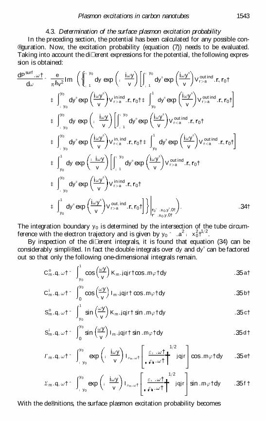
4.3. Determination of the surface plasmon excitation probabilityIn the preceding section, the potential has been calculated for any possible con-
® guration. Now, the excitation probability (equation (7)) needs to be evaluated.Taking into account the di� erent expressions for the potential, the following expres-sion is obtained:
dPsurf …!†d!
ˆe
p v2 Im… ¡ y0
¡ 1dy exp ¡
i!y
v
… ¡ y0
¡ 1dy
0 expi!y
0
vV
out indr>a …r; r0†
‡… y0
¡ y0
dy0 exp
i!y0
vV
in indr>a …r; r0† ‡
… 1
y0
dy0 exp
i!y0
vV
out indr>a …r; r0†
‡… y0
¡ y0
dy exp ¡i!y
v
… ¡ y0
¡ 1dy
0 expi!y
0
vV
out indr<a …r; r0†
‡… y0
¡ y0
dy0 exp
i!y0
vV
in; indr<a …r; r0† ‡
… 1
y0
dy0 exp
i!y0
vV
out indr<a …r; r0†
‡… 1
y0
dy exp¡ i!y
v
… ¡ y0
¡ 1dy
0 expi!y
0
vV
out indr>a …r; r0†
‡… y0
¡ y0
dy0 exp
i!y0
vV
in indr>a …r; r0†
‡… 1
y0
dy0 exp
i!y0
vV
out; indr>a …r; r0†
r0ˆ …x 0;y0;0†
rˆ …x0 ;y;0†
: …34†
The integration boundary y0 is determined by the intersection of the tube circum-ference with the electron trajectory and is given by y0 ˆ …a
2¡ x
20†1=2.
By inspection of the di� erent integrals, it is found that equation (34) can beconsiderably simpli® ed. In fact the double integrals over dy and dy
0 can be factoredout so that only the following one-dimensional integrals remain.
Com …q; !† ˆ
… 1
y0
cos!y
vKm …jqjr† cos …m’† dy …35 a†
Cim …q; !† ˆ
… y0
0cos
!y
vIm …jqjr† cos …m’† dy …35 b†
Som …q; !† ˆ
… 1
y0
sin!y
vKm …jqjr† sin …m’† dy …35 c†
Sim …q; !† ˆ
… y0
0sin
!y
vIm …jqjr† sin …m’† dy …35 d †
G m …q; !† ˆ
… y0
¡ y0
exp ¡i!y
vI¸m …!†
"? …!†"k …!†… †
1=2
jqjr
24
35cos …m’† dy …35 e†
S m …q; !† ˆ
… y0
¡ y0
exp ¡i!y
vI¸m …!†
"? …!†"k …!†… †
1=2
jqjr
24
35sin …m’† dy …35 f †
With the de® nitions, the surface plasmon excitation probability becomes
Plasmon excitations in carbon nanotubes 1543
dPsurf …!†d!
ˆ¡ e
2
4p3"0 v2
X
m 5 0
…2 ¡ ¯0;m †
… 1
¡ 1dq …4 Im ‰A 0 …q; !†Šf C
om …q; !†‰ Š2‡ S
om…q; !†‰ Š2g
‡ 4 Im ‰C 0 …q; !†Š‰C om …q; !†C
im …q; !† ‡ S
om …q; !†S
im …q; !†Š
‡ 2 Im fB0m…q; !†‰C o
m …q; !†G m…q; !† ‡ iS om…q; !†S m…q; !†Šg
‡ 2 Im fD0
m …q; !†‰C im …q; !†G m …q; !† ‡ iS i
m …q; !†S m …q; !†Šg† …36†
where
A0
m…q; !† ˆAm…q; !†Km…jqjr0†
; …37 a†
B0m…q; !† ˆ
Bm …q; !†Km…jqjr0†
; …37 b†
C0m…q; !† ˆ
C m…q; !†Im …jqjr0†
…37 c†
and
D0
m …q; !† ˆD m…q; !†Im …jqjr0†
: …37 d †
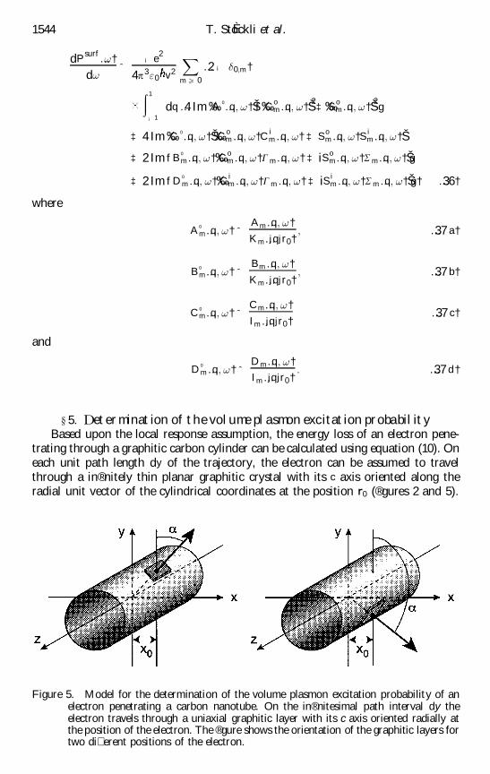
} 5. Determination of the volume plasmonexcitationprobabilityBased upon the local response assumption, the energy loss of an electron pene-
trating through a graphitic carbon cylinder can be calculated using equation (10). Oneach unit path length dy of the trajectory, the electron can be assumed to travelthrough a in® nitely thin planar graphitic crystal with its c axis oriented along theradial unit vector of the cylindrical coordinates at the position r0 (® gures 2 and 5).
1544 T. StoÈ ckli et al.
Figure 5. Model for the determination of the volume plasmon excitation probability of anelectron penetrating a carbon nanotube. On the in® nitesimal path interval dy theelectron travels through a uniaxial graphitic layer with its c axis oriented radially atthe position of the electron. The ® gure shows the orientation of the graphitic layers fortwo di� erent positions of the electron.
The angle ¬ between the c axis of the oriented piece of graphite and the trajectoryof the electron depends on the position of the electron. If the position is parametrizedby y (distance of the electron to the (x ; z) plane) , then
cos ¬ ˆy
…x 20 ‡ y2†1=2 …38 a†
and
sin ¬ ˆx 0
…x 20 ‡ y2†1=2 : …38 b†
The volume plasmon excitation probability of an electron penetrating a carbonnanotube can then be obtained from equation (10) by numerical integration overthe trajectory of the electron:
dPvolume…!†
d!ˆ
… y0
¡ y0
dyd2
Pvolume…!; y†d! dy
; …39†
where y0 is given as before by y0 ˆ …a2
¡ x20†1=2. With the explicit expression for the
surface and volume plasmon excitation probabilities (equations (36) and (39)) thetotal plasmon excitation probability of a carbon nanotube is
dPtotal…!†d!
ˆdP
volume…!†d!
‡dP
surf ace…!†d!
: …40†
As mentioned in } 3, the inner cavity of a carbon nanotube might be of importancefor the volume plasmon excitation probability. In order not to overestimate thisprobability we propose to adapt the integration range for this case:
dPvolume…!†
d!ˆ
… ¡ yi
¡ y0
dyd2
Pvolume…!; y†d! dy
‡… y0
y i
dyd2
Pvolume…!; y†d! dy
: …41†
y i ˆ …r2i ¡ x
20†1=2, where r i is the radius of the inner cavity, so that the integration
only takes into account the ® lled part of the cylinder.
} 6. ConclusionIn a recent publication (StoÈ ckli et al. 1998a) it has been shown by means of the
example of nested concentric-shell fullerenes that the inclusion of anisotropy in thenon-relativistic local dielectric response theory for the excitation of the plasmons ofcarbon nanostructures introduces important changes compared with the isotropicmodel. Since then, experimental EELS data of multishell fullerenes have becomeavailable (StoÈ ckli et al. 1998b). The comparison of those data with the simulationse� ectuated with the two formalisms (isotropic and anisotropic) shows that the inclu-sion of anisotropy in the model is essential in order to reproduce the data. Thecalculations presented in this contribution represent a straightforward continuationof the work on the theoretical background for the interpretation of plasmon losselectron-energy-loss spectra of graphitic carbon nanoparticles. In fact, the formalismdeveloped here allows electron-energy-loss spectra of carbon nanotubes to be simu-lated as a function of their geometrical parameters for any impact parameter(electron passing inside and outside the particle) as well as intensity line pro® les ofenergy-® ltered images. It represents one of the missing pieces for better understand-ing of the physical properties of carbon nanostructures. We are con® dent that a
Plasmon excitations in carbon nanotubes 1545
detailed comparison of the experimental data of nested concentric-shell fullerenesand multiwall carbon nanotubes with simulations of the plasmon excitationprobabilities based on our calculations will contribute to a better understanding ofthe physical properties of multiwall carbon nanostructures. In particular, it will bepossible with our model to investigate how the intrinsic properties of multishellfullerenes di� er from those of multiwall nanotubes and from those of planar gra-phite.
ACKNOWLEDGEMENTS
This work was partially ® nanced by the Swiss National Science Foundation,under grant 2100-037660. Their support is gratefully acknowledged.
A P P E N D I X AFrom the ® rst of the Maxwell inhomogeneous equations relating the displace-
ment ® eld to the charge density and the phenomenological relation between thedisplacement and the electric ® eld the following equation for the electric ® eld insidean in® nitely large medium with the anisotropy of a carbon nanotube is found:
Ñ r·~"…!†E…r; r0† ˆ»…r; r0†
"0: …A 1†
The charge density represents the incoming probe electron and can be written interms of a Dirac function:
»…r; r0† ˆ ¡ e¯…r ¡ r0†: …A 2†
In order to solve this inhomogeneous equation we introduce the scalar functionF …r; r0† de® ned by
~"…!†E…r; r0† ˆ ¡ Ñ rF…r; r0†: …A 3†
Equation (A 1) then becomes
r2r F …r; r0† ˆ
e
"0¯…r; r0†: …A 4†
Formally this equation is identical with the Laplace equation. However, F …r; r0† isnot the Coulomb potential, but only a mathematical construction introduced forconvenience. From equation (A 4) it is found that F …r; r0† is given by
…r; r0† ˆ ¡e
4p"0jr ¡ r0j
ˆ ¡e
2p"0
X
m 5 0
…2 ¡ ¯0;m † cos ‰m…’ ¡ ’0†Š… 1
¡ 1
dq
2pexp …iqz† Lm …jqjr ; jqjr0†;
…A 5†
where the function Lm …jqjr ; jqjr0† is given in equation (18 b). Using the de® nition ofthe function F …r; r0† and the gradient in cylindrical coordinates, the electric ® eld isobtained from equation (A 5):
1546 T. StoÈ ckli et al.
E…r; r0† ˆ ¡e
2p"0
X
m 5 0
…2 ¡ ¯0;m†… 1
¡ 1
dq
2p
1"k …!†
exp …iqz† cos ‰m…’ ¡ ’0†Š @
@ rL m…jqjr ; jqjr0†
¡1
"? …!†exp …iqz†
m sin ‰m…’ ¡ ’0†Šr
L m …jqjr ; jqjr0†
1"? …!†
iq exp …iqz† cos ‰m…’ ¡ ’0†ŠL m …jqjr ; jqjr0
0
BBBBBBBBB@
1
CCCCCCCCCA
: …A 6†
ReferencesAjayan, P. M., Iijima, S., and Ichihashi, T., 1992, Phys. Rev. B, 47, 6859.Bachtold, A., Henry, M., Terrier, C., Strunk, C., Schoïnenberger, C., Salvetat,
J.-P., Bonard, J.-M., and Forroí, L., 1998, Appl. Phys. L ett., 73, 274.Bausells, J., Rivacoba, A., and Echenique, P. M., 1987, Surf. Sci., 190, 1015.Bezryadin, A., Verschueren, A. R. M., Tans, S. J., and Dekker, C., 1998, Phys. Rev.
L ett., 80, 4036.Bonard, J.-M., Stoïckli, T., de Heer, W. A., CHAÃ TELAIN, A., Charlier, J.-C., Blase, X., De
Vita, A., Car, R., Salvetat, J.-P., and Forroí, L.,1997a, Phys. Rev. L ett., (submitted).Bonard, J.-M., Stora, T., Salvetat, J.-P., Maier, F., Stoïckli, T., Duschl, K., Forroí,
L., de Heer, W., and Chatelain, A., 1997b, Adv. Mater., 9, 827.Bursill, L. A., Stadelmann, P. A., Peng, J. L., and Prawer, S., 1992, Phys. Rev. B, 49,
2882.Carroll, D. L., Redlich, P., Ajayan, P. M., Charlier, J.C.,Blase,X.,DeVito, A., and
Car, R., 1997, Phys. Rev. L ett., 78, 2811.Chu, Y. T., Warmack, R. J., Ritchie, R. H., Little, J. W., Becker, R. S., and Ferrell,
T. L., 1984, Particle Acceleration, 16, 13.Daniels, J., Festenberg, C., Raether, H., and Zeppenfeld, K., 1979, Optical Constants of
Solids by Electron Spectroscopy (Berlin: Springer Verlag).de Heer, W. A., Chatelain, A., and Ugarte, D., 1995, Science, 270, 1179.Dujardin,E.,Ebbesen,T.W.,Krishnan,A., and Treacy,M.M.J.,1998, Adv. Mater., 10,
611.Ebbesen, T. W., and Ajayan, P. M., 1992, Nature, 358, 220.Echenique, M., Howie, A., and Wheatley, D. J., 1987, Phil. Mag. B, 56, 335.Egerton, R. F., 1996, Electron Energy-L oss Spectroscopy in the Electron Microscope (New
York: Plenum Press).Ferrell,T.L.,Anderson,V.E.,Echenique,P.M., and Warmack,R. J.,Phys. Rev. B, 35,
7365.Ferrell, T. L., and Echenique, P. M., 1985, Phys. Rev. L ett., 55, 1562.Frank, S., Poncharal, P., Wang, Z. L., and de Heer, W. A., 1998, Science, 280, 1744.Hamada, N., Sawada, S., and Oshiyama, A., 1992, Phys. Rev. L ett., 68, 1579.Hubbard, J., 1955a, Proc. Phys. Soc. A, 68, 976; 1955b, ibid. 68, 441.Iijima, S., 1991, Nature, 354, 56.Jackson, J. D., 1975, Classical Electrodynamics (New York: Wiley).Journet, C., Maser, W. K., Bernier, P., Loiseau, A., Lamy de la Chapelle, M.,
Lefrant, S., Deniard, P., Lee, R., and Fischer, J. E., 1997, Nature, 388, 756.Kraïtschmer, W., Lamb, L. D., Fostiropoulos, K., and Huffman, D. R., 1990, Nature,
347, 354.Kroto, H. W., Health, J. R., O’Brian, S. C., Curl, R. F., and Smalley, R. E., 1985,
Nature, 381, 162.Kuzuo, R., Terauchi, M., and Tanaka, M., 1992, Jap. J. appl. Phys., Pt 2, 31, L1484.Lucas, A. A., Henrad, L., and Lambin, P., 1994, Phys. Rev. B, 49, 2888; 1995, Nuclear
Instruments Meth. B, 96, 465.Mintmire, J. W., Dunlap, B. I., and White, C. T., 1992, Phys. Rev. L ett., 68, 631.
Plasmon excitations in carbon nanotubes 1547
Ritchie, R. H., 1957, Phys. Rev., 106, 874.Rivacoba, A., Apell, P., and Zabala, N., 1995, Nucl. Instrum. Meth. B, 96, 470.Saito, R., Fujita, G., Dresselhaus, G., and Dresselhaus, M. S., 1992, Appl. Phys. L ett.,
60, 2204.Salvetat, J.-P., Kulik, A. J., Briggs, G. A. D., Bonard, J.-M., Stoïckli, T., Burnham,
N., and Forroí, L., 1999, Adv. mater., 11, 161.Steíphan, O., Ajayan, P. M., Colliex, C., Cyrot-Lackmann, F., and Sandreí, E., 1996,
Phys. Rev. B, 53, 13824.Stoïckli, T., Bonard, J.-M., Chatelain, A., Wang, Z. L., and Stadelmann, P., 1998a,
Phys. Rev. B, 57, 15599.Stoïckli, T., Bonard, J.-M., Stadelmann, P. A., and Chatelain, A., 1997a, Z. Phys. D,
40, 425.Stoïckli, T., Stadelmann, P. A., and Chatelain, A., 1997b, Microsc. Microanal. Micro-
struct., 8, 145.Stoïckli, T., Wang, Z. L., Bonard, J.-M., Stadelmann, P., and Chatelain, A., 1998b,
Proceedings of 12th International Winterschool of the Electronic Properties of NovelMaterials, edited by H. Kuzmany, J. Fink, M. Mehring and S, Roth. (New York:American Institute of Physics). pp. 439± 442.
Tans, S. J., Devoret, M. H., Dai, H., Thess, A., Smalley, R. E., Geerligs, L. J., andDekker, C., 1997, Nature, 386, 474.
Thess, A., Lee, R., Nikolaev, P., Dai, H., Petit, P., Robert, J., Xu, C., Lee, Y. H., Kim,S. G., Colbert, D. T., Scuseria, G., Tomanek, T., Fischer, J. E., and Smalley,R. E., 1996, Science, 273, 483.
Tosatti, E., 1969, Nuovo Cim. B, 63, 54.Ugarte, D., 1992, Nature, 359, 707.Ugarte, D., Colliex, C., and Trebbia, P., 1992, Phys. Rev. B, 45, 4332.Walsh, C. A., 1991, Phil. Mag. B, 63, 1063.Wang, Z. L., 1996, Micron, 27, 265.Wang, Z. L., and Cowley, J. M., 1987, Ultramicroscopy, 21, 77.Watson, G. N., 1996, A Treatise on the Theory of Bessel Functions (Cambridge University
Press).Wessjohann, H. G., 1974, Z. Phys., 269, 269.Yase, K., Horiuchi, S., Kyotani, M., Yumura, M., Uchida, K.,Ohshima, S., Kuriki, Y.,
Ikazaki, F., and Yamahira, N., 1996, Thin Solid Films, 273, 222.Zabala, N., and Rivacoba, A., 1991, Ultramicroscropy, 35, 145.Zabala, N., Rivacoba, A., and Echenique, P. M., 1989, Surf. Sci., 209, 465.


![From surface plasmon resonance based sensors to carbon … · 2017. 2. 3. · est: sensors based on surface plasmon resonance (SPR) [5] and sensors based on carbon nanotubes (CNTs)](https://static.documents.pub/doc/80x56/5fce048a0b8c9d11763a185e/from-surface-plasmon-resonance-based-sensors-to-carbon-2017-2-3-est-sensors.jpg)

![Review Article A Review of Computational Electromagnetic ...et al. [ ] used metamaterial made up of periodic graphene microribbon arrays for terahertz plasmon excitations and demonstrated](https://static.documents.pub/doc/80x56/60bf77d5262f570c1e13764b/review-article-a-review-of-computational-electromagnetic-et-al-used-metamaterial.jpg)


