Scholars' Mine Scholars' Mine Masters Theses Student Theses and Dissertations 1966 Plastic design of steel frames for minimum weight Plastic design of steel frames for minimum weight I-Chen Hung Follow this and additional works at: https://scholarsmine.mst.edu/masters_theses Part of the Civil Engineering Commons Department: Department: Recommended Citation Recommended Citation Hung, I-Chen, "Plastic design of steel frames for minimum weight" (1966). Masters Theses. 5790. https://scholarsmine.mst.edu/masters_theses/5790 This thesis is brought to you by Scholars' Mine, a service of the Missouri S&T Library and Learning Resources. This work is protected by U. S. Copyright Law. Unauthorized use including reproduction for redistribution requires the permission of the copyright holder. For more information, please contact [email protected].
Transcript
Scholars' Mine Scholars' Mine
Masters Theses Student Theses and Dissertations
1966
Plastic design of steel frames for minimum weight Plastic design of steel frames for minimum weight
I-Chen Hung
Follow this and additional works at: https://scholarsmine.mst.edu/masters_theses
Part of the Civil Engineering Commons
Department: Department:
Recommended Citation Recommended Citation Hung, I-Chen, "Plastic design of steel frames for minimum weight" (1966). Masters Theses. 5790. https://scholarsmine.mst.edu/masters_theses/5790
This thesis is brought to you by Scholars' Mine, a service of the Missouri S&T Library and Learning Resources. This work is protected by U. S. Copyright Law. Unauthorized use including reproduction for redistribution requires the permission of the copyright holder. For more information, please contact [email protected].
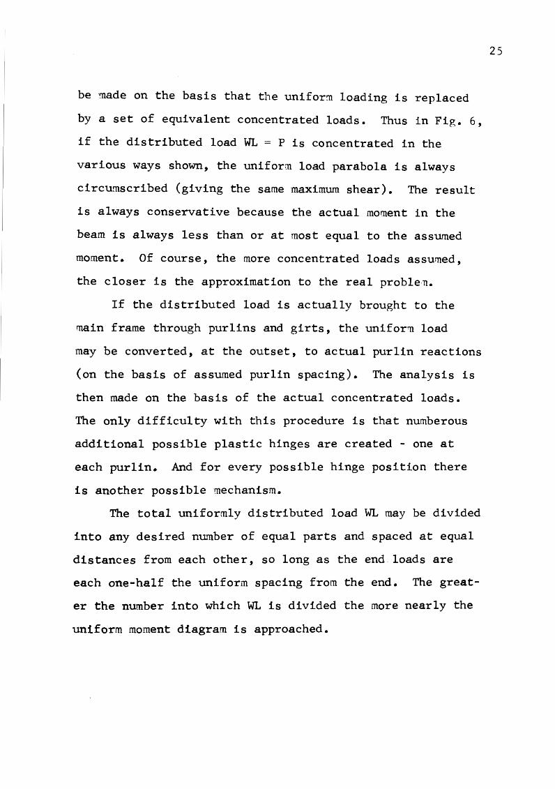
Frame weight vs. span length for a fixedbased portal frame • • • • • • • • • • • • . . . . 33
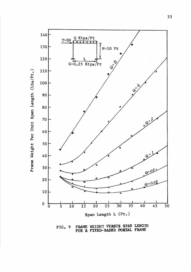
10. Axial load of column vs. span length for a fixed end portal frame.. • • • • • • • • • • • • • • • • 34
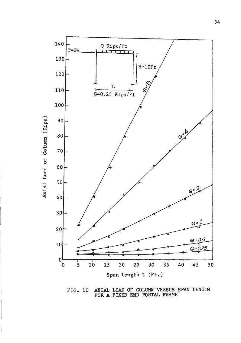
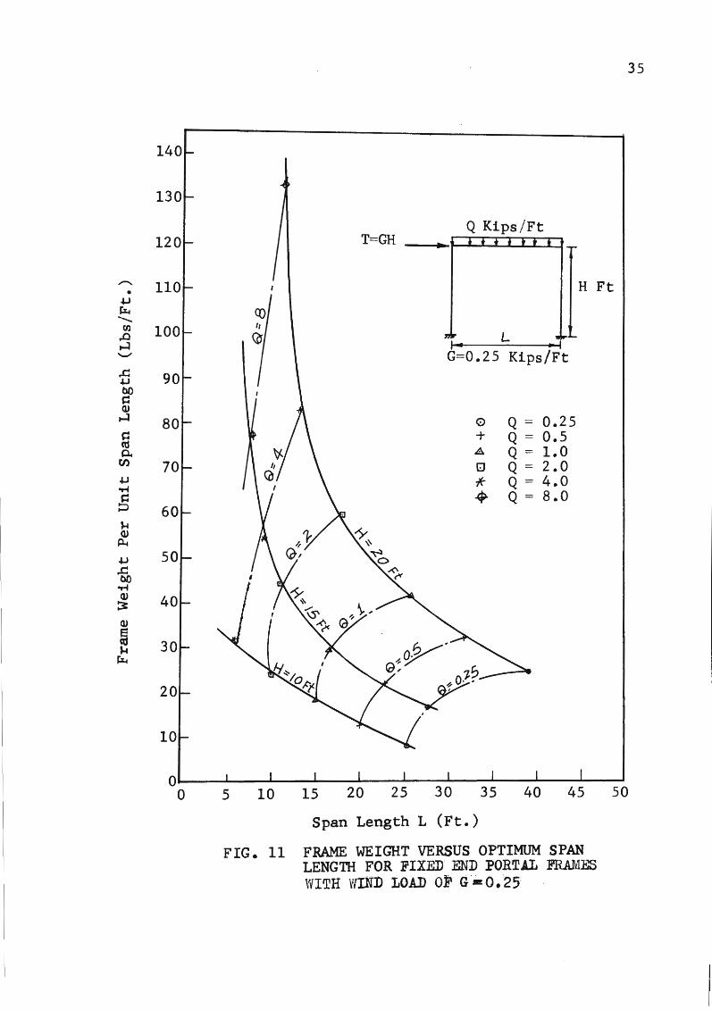
11. Frame weight vs. optimum span length for a fixed end portal frame with wind load of 0.25. • • • • • 35
12. Frame weight vs. optimum span length for a fixed end portal frame with wind load of 0.5 • • • • • • 36
13. Frame weight vs. optimum span length for hinp;ed end portal frames with wind load of 0.25 • • • • • 37
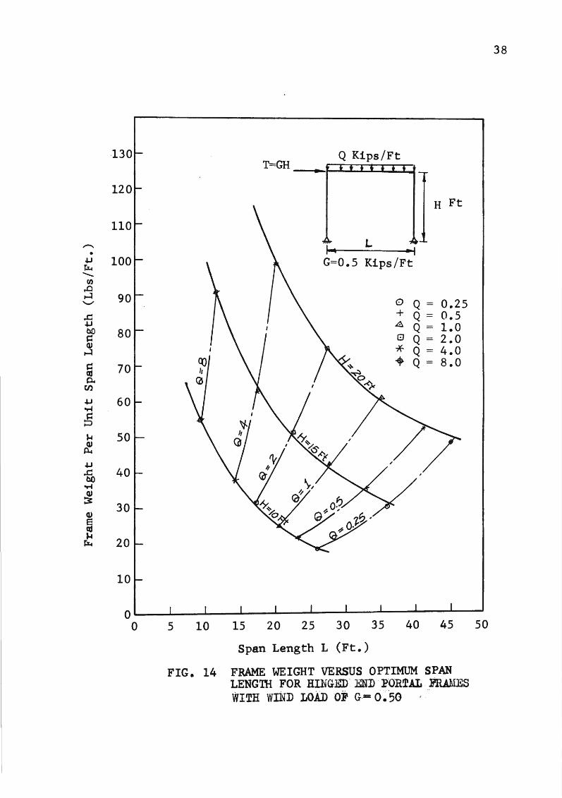
14. Frame weight vs. optimum span length for hinged end portal frames with wind load of 0.5. • • • • • 38
vi
a"' bi b"' Cj
Cj
Ctc:
f Fw F~ G H Mp Mo
m
Q R r" WaA.
T Wi WK Xr X.z Xj Xn•i Xn.,..m-rj e =
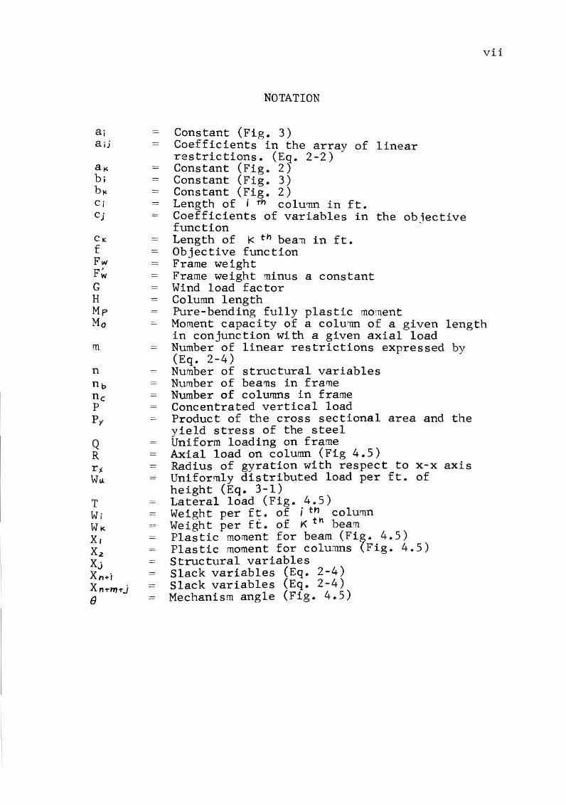
NOTATION
Constant (Fig. 3) Coefficients in the array of linear restrictions. (Eq. 2-2) Constant (Fig. 2) Constant (Fig. 3) Constant (Fig. 2) Length of i th colu11n in ft. Coefficients of variables in the objective function Length of I< th bea:n in ft. Objective function Frame weight Frame weight minus a constant Wind load factor Column length Pure-bending fully plastic moment
vii
Moment capacity of a column of a given length in conjunction with a given axial load Number of linear restrictions expressed by (Eq. 2-4) Number of structural variables Number of beams in frame Number of columns in frame Concentrated vertical load Product of the cross sectional area and the yield stress of the steel Uniform loading on frame Axial load on column (Fig 4.5) Radius of gyration with respect to x-x axis Uniformly distributed load per ft. of height (Eq. 3-1) Lateral load (Fig. 4.5) Weight per f~. of i tnh column Weight per ft. of K t beam Plastic moment for beam (Fig. 4.5) Plastic moment for columns (Fig. 4.5) Structural variables Slack variables (Eq. 2-4) Slack variables (Eq. 2-4) Mechanism angle (Fig. 4.5)
I. INTRODUCTION
1.1 General Remarks
The determination of the maximu~ load carrying capac
ity of a given frame is a problem for which only one
answer exists; many feasible designs for a given geo~etry
and loadit?-g may exist. Only one solution, however, pro
vides the minimum cost design, or, as will be considered
in this study, the minimum-weight design.
The indeterminate structure, when designed on the
basis of elastic analysis, requires a method of trial to
approach the minimum-\veight design. This fact is manifest
ed by the presence of the stiffness or flexibility factor
in the matrix of coefficients which relate the redundant
moments;it is usually found that different rne11ber sizes are
required whereupon further analysis is necessary.
With the development of tte plastic. :nethod of analysis
however, there is now the possibility of the deter~ination
of an admissible distribution of moments over an indeter
minate structure without an estimate of the ~ember sizes
having been made beforehand. This is because the :natrix of
coefficients which relate the critical ~aments are ftlnc
tions of the geometry of the structure and of the hinge
positions, and are independent of member sizes.
Since member sizes do not have to be estimated before
an analysis is made, one can determine a distribution of
moments for a given structure which will yield a minirnum-
1
weight solution. In order that this may be acco~plished,
suitable relationships between weight of Tie~ber and ~o~ent
capacity of both beams and columns must be established. In
addition, a method of proceeding efficiently from one dis
tribution of moments to another which will yield a light
weight structure must be developed.
1.2 Object and Scope
1. The object of this study is to develop a ~ethod
for the minimum-weight design of steel structures, based on
plastic analysis, which satisfies the following require
ments:
a. The method will embrace the problem of axial
compression as well as flexural loading, lateral
displacement (sidesway) of the structure, and the
non-linear relationship between unit weight of
members and their moment capacities.
b. The method will allow the determination of mini~u~
weight for the structure which is designed for
standard structural shapes as well as the struc
ture for which a continuous spectrum of shapes rnay
be available.
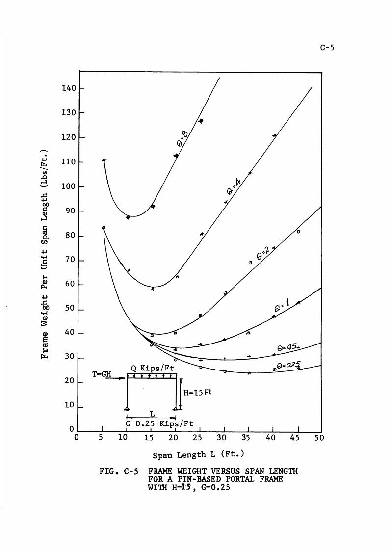
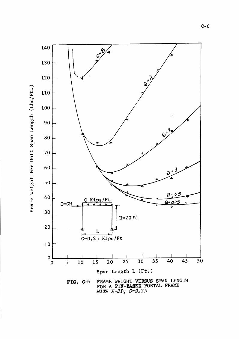
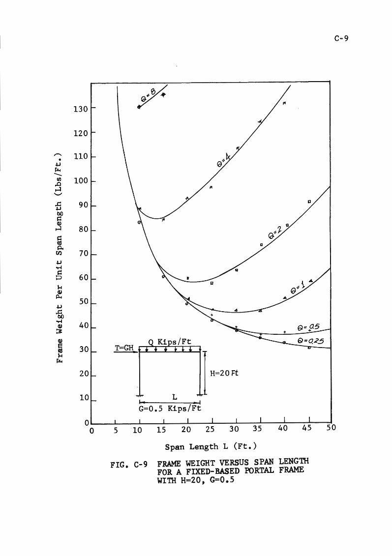
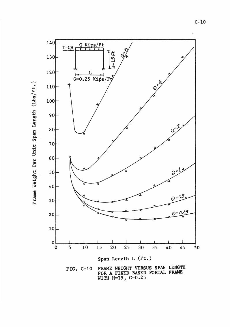
2. Design charts are developed for si~ple rortal
frames.
1.3 Outline of Project
The problem considered in this study 'nay be stated as
2
follows: Given a set of static loads, acting at certain
fixed poin-ts of a . rigi'd-'j.Ointed plane frame of prescribed
geometrical form, how should the cross sectional dimensions
of the members be chosen to .produce the lightest possible
frame capable of carrying the loads? The members are re
quired to be straight and of constant cross-section
throughout their length.
To determine whether a frame will support the loads
applied to it the theory of plastic collapse vall be used.
This theory applies to structures made of a ductile mater
ial, and assumes that if the curvature of a member becomes
infinitely large the bending moment tends to a maxim~~
value, called the fully plastic moment, which depends only
on the section dimensions.
The problem is to minimize the weight of the frame
subject to certain constraining conditions. These conditions
are imposed by the fact that the moments in the structure
must be ~n equilibrium with the known external loads, and
must be less than or equal to the fully plastic moments of
the members in which they occur. Mathematically, therefore,
the problem is one of minimizing a linear function of sev
eral variables subject to a: set of linear inequalities.
This is the basic problem of linear programming.
This study develope an alternative system of analysis
which provides an exact solution of the general problem,
and which is particularly suitable for use on a digital
3
computer. Two general cases of simple portal framef:
analyzed and the design charts are plotted.
1.4 Review of Literature
Using concepts of plastic analysis, several research
ers have made attempts to establish a minimum-weight design
procedure for ultimate loading. J. Foulkes and J. Heyman
(5)* have proposed a trial-and-error mechanism method that
seems feasible only for simple structures. Foulkes (6) rnade
a geometric interpretation of the work equations and sue-
ceeded in establishing a design chart for the si~ple case
of a one story single-bay frame. Prager (21) later refined
4
Foulkes' work by considering a nonlinear form of the weight
strength function and showed how the design chart for a por
tal frame was changed thereby. P.G. Hodge (12) investigated
a method for minimum-weight design that does not depend on
theoretical weight-strength functions, but works directly
with the available sections. Because this is a trial-and-
error solution, it would be too laborious for a complex
frame.
In the case of multistory frames, the axial load
effects are important. Their stability should be checked
at the time of selection, as a normal design procedure. The
effect of the axial forces and the stability of the beam
column to the minimum-weight problem will be considered in
*The number in parentheses refers to bibliographical entries.
this study.
Since the majority of structur2s for which plastic
analysis is presently considered appropriate are con
structed of available standard structural shapes, a ~ethod
which is to be useful to the designer ~ust, in its final
application, relate the minimum-weight problem to the pro
perties of these shapes rather than to a continuous spectrum
of shapes.
5
II. DEVJ:iLOPMENT OF MATHEMATICAL SOLUTION
2.1 General Remarks
The ·method of inequalities could be easily adapted to
the problem o:f designing a,· frame for minimum weight i:f the
weight per unit length of a structural member could be
taken as linear and proportional to the fUlly plastic bending
moment of this member. Under this assumption the minimum
weight design of a structural frame constitutes a problem
in linear programming.
2.2 Assumptions and Limitations
a. This study is limited to frames in one plane,
composed of rigidly jointed or pin-jointed mem
bers, which are braced normal to their plane of
action.
b. Only prismatic steel members whose cross sections
have an axis of symmetry- lying in the plane of the
structure are considered.
c. All loads act in the plane of the structure.
d. Lateral loads act only at the joints.
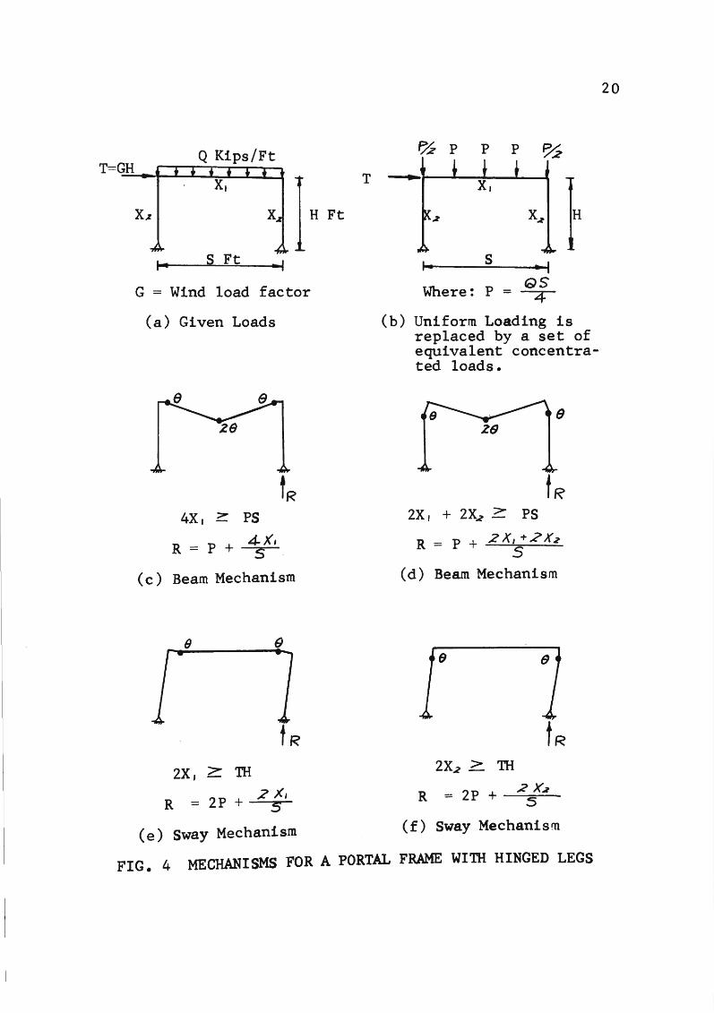
e. The distributed load is replaced by a set of equiv-
alent concentrated loads.
f. Beam-columns are assumed to be subjected only to
bending when the ratio of applied load to plastic
, axial load is less or equaJ. to 0.15.
g. Further restrictions applying to particular prob-
6
le~s will be discussed as they arise.
2.3 The Minimization Problem
For a given load system and structure geometry, many
feasible designs may be deter~ined. Mathematically this
fact is expressed by the existence of more unknowns than
there are equations which relate the unknowns. Further
more, the distribution of moments over the structure at the
ultimate load is influenced by the relative moment capaci
ties of the various members. This fact becomes evident if
the structure is observed during the last stages of loading
leading to the ultimate load. As the ultimate load is ap
proached, each succeeding hinge brings about a redistribu
tion that would have prevailed had the structure remained
elastic.
The desired method should proceed from the first solu
tion to the minimum-weight solution with the consideration
of only a very small percentage of the possible solutions.
Furthermore, it should proceed from one solution to the
next without having to restart the solution process.
Finally, a criterion to identify the minimum-weight solu
tion must be available.
Such a method exists. This method, known as linear
programming, was first developed by George B. Dantzig,
Marshall Wood, and their associates.
7
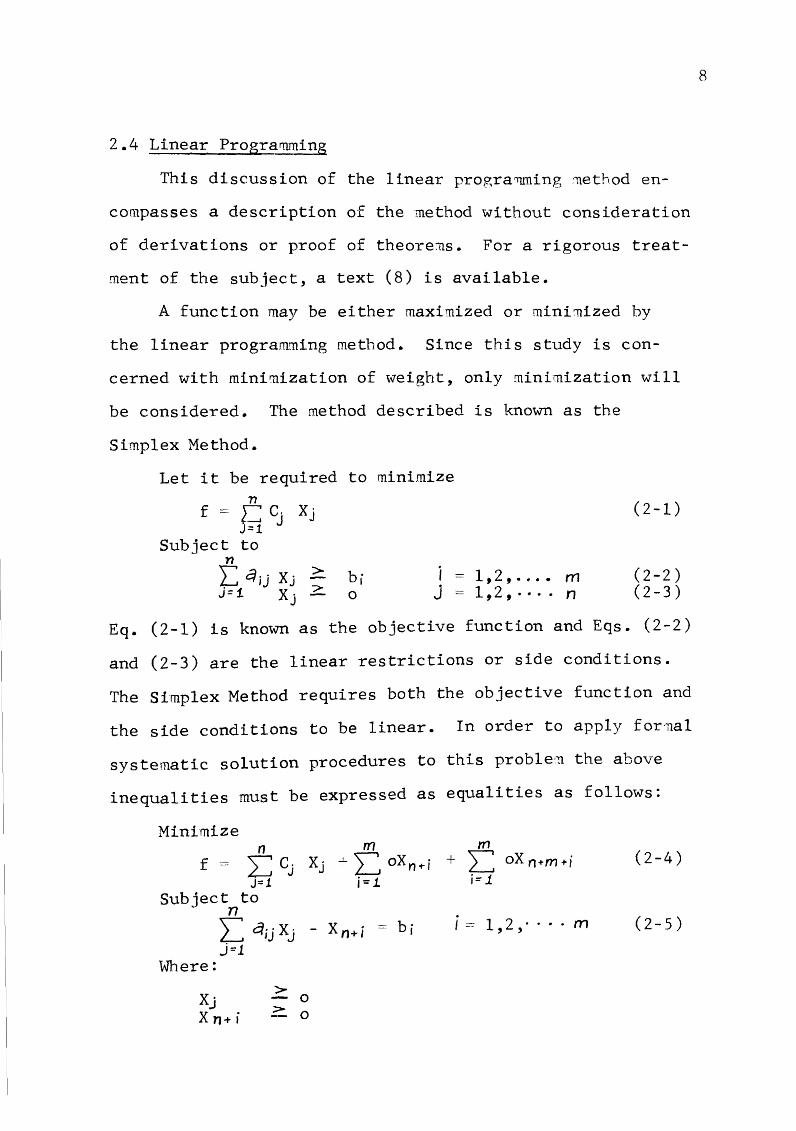
2.4 Linear Programming
This discussion of the linear progra'mning ;nethod en
compasses a description of the method without consideration
of derivations or proof of theore~s. For a rigorous treat
ment of the subject, a text (8) is available.
A function may be either maximized or mini·nized by
the linear program11ing method. Since this study is con-
cerned with minimization of weight, only minimization will
be considered. The method described is known as the
Simplex Method.
Let it be required to minimize n
f = §;1 cj Xj
Subject to n L qu xj > bi J= 1 Xj 2. o
i = 1,2, ...• rn J = 1,2, · · · . n
(2-1)
(2-2) (2-3)
Eq. (2-1) is known as the objective function and Eqs. (2-2)
and (2-3) are the linear restrictions or side conditions.
The Simplex Method requires both the objective function and
the side conditions to be linear. In order to apply for·nal
systematic solution procedures to this preble~ the above
inequalities must be expressed as equalities as follows:
Minimize n
f = 2: cj j= 1.
Subject to n L qijXj J=l
Where: >
- 0
m m Xj + Z oXn..-i + L oXn+m+i
i=i i= 1
i= 1,2,- ·· · m
Xj X n+ i ?-. 0
(2-4)
(2-5)
8
Xnotmi-i z 0 Xj - Structural variables Xn+i and X n+m+ i - Surplus variables au , bi , Cj ==Constant n ·~ · Number of structural variables nn ~ ~um~er of linear restrictions expressed
by EqJ (2-5)
2.5 Tne Artificial-Base Techniq~e
Instead of solving for an initial basic feasible sol
ution, we may _assume an entirely artificial one. To do
this, we simply add to our augmented matrix an identity
matrix consisting of the same number of new variables as we
have equations. These new variables must be included in
the objective function. However, we as sign them such arbi-
9
trarily large coefficients as to drive them from the solution.
The final solution is not valid unless all these artificial
variables are absent. Further explanation and proof of
y~idity of this technique may be found in Ref. (8).
2.6 The Objective Function
The objective function which is to be minirrl.zed in
order to determine a minimum-weight steel frame is that
function which expresses the total weight of the frame.
where
F.., - t C"' It< + f..c C; Wr (2-6) kc1- lei
Fw = Weight of frame CK = Length of K m beam in ft. Wt< - Weight per ft. of K ttl beam nb = .~ · ~~~ of beam in frame ·a, = Length of i th column in ft. li - Weight per ft. of i tn column nc - Number of columns in frame
Although Eq. (2-6) is exact, it cannot be used in its
present form because the side conditions provided by the
mechanism equations relate the moment capacities of the
individual rnembers and not their weight. In order to ef
fect compatibility between the objective function and the
side conditions, the weights of the me:nbers :nust be ex-
pressed as functions of their moment capacities. These re-
lationships will be considered separately for bea~s and
columns.
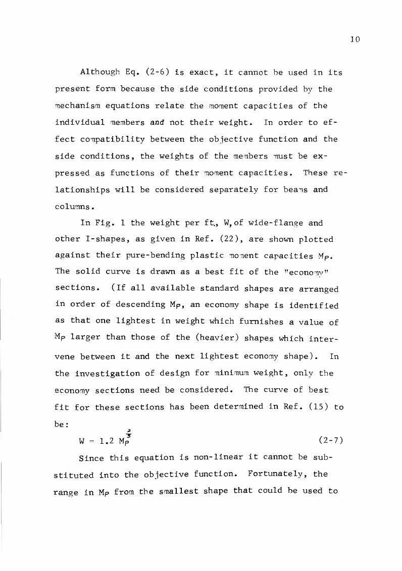
In Fig. 1 the weight perf~, W,of wide-flange and
other !-shapes, as given in Ref. (22), are shown plotted
against their pure-bending plastic 11onent capacities Mp.
The solid curve is drawn as a best fit of the TTecono'TlvTT
sections. (If all available standard shapes are arranged
in order of descending Mp, an economy shape is identified
as that one lightest in weight which furnishes a value of
Mp larger than those of the (heavier) shapes which inter-
vene between it and the next lightest econo~y shape). In
the investigation of design for minimum weight, only the
economy sections need be considered. The curve of best
fit for these sections has been determined in Ref. (15) to
be: ~
"'3" W = 1.2 Mp (2-7)
Since this equation is non-linear it cannot be sub
stituted into the objective function. Fortunately, the
range in Mp from the smallest shape that could be used to
10
the largest shape which probably would be used for a par
ticular loading is limited. For uniform load this range ~ ;l
would normally be from WL /16 to WL /8. A number of trials
showed that a straight line gives a good fit t~ the plot of
economy sections for particular conditions of geom~try and
loaing and for a reasonable range of Mp • Line AB of
Fig. 2 is ·typical. Therefore, we may write
Wt< == qtc: + bt< Mpt< (2-8)
where Mp~e .. Plastic moment capacity of the K th beam.
As in the case of .· beams, only the economy sections
need be considered for col~a for the minimum-weight
problem. The range of Mp fer·· the column will normally
extend from the smallest shape that could be used to the
maximum Mp , the column would receive from adjacent beams.
Line C-D, Fig. 3, is a typical best-fit straight line. The
equation is
(2-9)
where Mp; - Plastic moment capacity of the i thcolumn.
The objective function, Eq. (2-6) is now expressed as
etc., may need to be considered. Upon checking the adequacy
of the minimum-weight design against these so-called sec
ondary criteria, it may be found necessary to change one or
more members. The computer program, however, provides a
method of solution so rapid and automatic that it may be of
value in giving the engineer a rough guide in the initial
stages of his design work.
41
1.
2.
3.
4.
5.
6.
7.
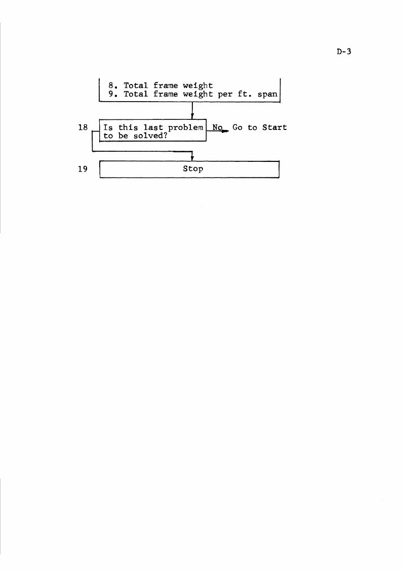
8.
9.
10.
11.
12.
BIBLIOGRAPHY
BAKER, F .J., HORNE, M.R., and HEYMAN, J., "The Steel Skeleton, Vol. II: Plastic Behavior and Design", Cambridge Univ. Press, Cambridge, England, 1956.
BEEDLE, L.So, "Plastic Design of Steel Frames", John Willy and Sons, New York, 1958.
"Commentary on Plastic Design in Steel", American Society of Civil Engineers, Manuals of Engineering Practice, No. 41, adopted 1961.
ENGLISH, J .M., "Design of Frames by Relaxation of Yield Hinges" Transactions, ASCE, Vol. 119, 1954.
FOULKES, J., "Minimum Weight Design and the Theory of Plastic Collapse", Quarterly of A~~lied Mathematics, Vol. 10, January, 1953, pp. 7-358.
FOULKES, J., "The minimum weight design of structural frames", Proceeding of the Royal Society, London, England, Vol. 223, 1954, pp. 482-494.
GALAMBOS, T.V. and R.L. KETTER, "Columns under combined bending and thrust", Proceedings of the American Society of Civil Engineers, Vol. 85, No. EM2,April, 1959, pp. 1-30.
GASS, S.I., "Linear programming methods and Applications", McGraw-Hill, New York, 1958.
GREENBERG, H .G., and PRAGER, W., "Limit design of beams and frames", Transactions, ASCE, Vol. 117, 1952, p. 447.
HEYMAN, J., and W. PRAGER, "Automatic Minimum Weight Design of Steel Frames", Journal of the Franklin Institute·, Vol. 266, p. 339.
HEYMAN, Jo, "On the absolute minimum-weight design of framed structures", Quarterly Journal of Mechanics and Applied Mathematics, Vol. 12, 1959, p. 314.
HODGE, P.G., JR., "Plastic analysis of structures", McGraw-Hill, New York, 1959.
42
13.
14.
15.
16.
17.
18.
19.
20.
21.
22.
HORNE, M.R., "A moment distribution method for rigid frame steel structures loaded beyond the yield point", Welding Research, Vol. 1, 1947, p.6.
HORNE, M.R., TTA moment distribution method for the analysis and design of structures by the plastic theory", Proceeding of the Institute of Civil Engineers, Vol. 3, Part 3, April, 1954, p. 51.
KETTER, ROBERT L., Discussion of "Minimum-Design of a portal frame", by W. Prager, Transactions, ASCE, Vol. 123, 1958, p. 66.
LIVESLEY, R.K., TTThe automatic design of structural framesn, Quarterly Journal of Mechanics and Applied Mathematics, Vol. 8, Part 3, September, 1956' p. 257,.
MASSONET, C., "Stability considerations in the design of steel columns," Proceeding of the American Society of Civil Engineers, Vol. 85, No. st 7, September, 1959, p. 75.
NEAL, B .G., and SYMONDS, P .S., "The Rapid Calculation of the Plastic Collapse load for a Fra~ed Stuc.ture", Proceeding, Institution of Civil Engineers, Vol. I, Part III, 1952, p. 58.
ORDEN, A., "Application of the Simplex method to a Variety of Matrix Problem", Director of Management Analysis (35).
"Plastic Design in Steel", American Institute of Steel Construction, 1959.
PRAGER, w., "Minimum-weight design of a portal fra:ne", Transactions, ASCE, Vol. 123, p. 66.
"Manual of Steel Construction", Sixth Edition, American Institute of Steel Construction, 1964.
43
VITA
I - Chen Hung was born on February 16, 1938, in Yen
Shui, Taiwan, China, the son of Mr. and Mrs. Tsu Hung.
He received his secondary education at Taiwan
Provincial Tainan First Middle School, Tainan, Taiwan,
China. In September, 1956, he entered Taiwan Provincial
Cheng Kung University as a fresh~an in Civil Engineering,
and received his Bachelor of Science degree in Civil
Engineering in July, 1960. After his graduation, he spent
one year as a second lieutenant in the Chinese Air Force.
In January, 1965, he ca~e to the United States and
then enrolled as a graduate student at the University of
Missouri at Rolla, for work toward his Master of Science
degree in Civil Engineering.
44
A-1
APPENDIX A Illustrative Example
Example ·; 1: Given:
Roof load= 36 L.b~q Ft. Wind load= 18 LbYsq Ft. Frames are 20' on center Load factor= 1.4
t. .. 20'
10' Design the frame for
minimum weight
R f 1 d - 36 .x .ZOJ< '·4- 1 Ki J.Li oo oa - 7000 - p-.. ntl Ft.
Wind force = 18 x .zox5 ;e 1•4 /ooo = 2.52 Kips
From Fig. 7 and Fig. 8 we get:
Mp (beam) = 39.33 Mp (column) = 14.85
Refer to Appendix B. The sections are selected as:
Beam - 12JR11.8 Column - 8JR6.5
The Critical Mechanism is Composite Mechanism.
Exa·mple 2:
From Fig. 7 and Fig. 8 we get:
Mp (beam) = 120.73 Mp (column) = 120.73
Given:
Same as Example 1, except span length :· i s 40 Ft.
Refer to Appendix B. The sections are selected as~
Beam - 16B26 Column - 16B26
The Critical Mechanism is Beam Mechanism.
B-1
APPENDIX B Properties of Economic Sections (A-7 Steel)
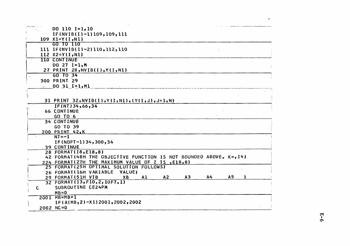
DO 110 1=1,10 IF(NVIB(l)-1)109,109,111 X1=Y(I,Nl) GO- TO 110 -- -- - ---IF(NVIB(Il-21110,112,110 X2=Y(I,NlJ CnNT lNUE DO 27 l=l,M
27 PRINT 28,NVIB(I),Y(I,Nl) GO TO 34
__ PRINT '29 300 . ; -. Q9 -~ -1_1_==-h_M l
·f
.. i
PRINT 32 t NV I.B ( I ) , Y (It N 1), ( Y ( I , J) t J= 1 t N)
NT=-1 IF(NOPT-1)34,300,34 CONTINUE FORMAT(I8,El8.8) FORMAT(48H THE OBJECTIVE FUNCTIO~ IS NOT BOUNDED ABOVE. K=,I4) FORMAT(27H THE MAXIMUM VALUE OF Z IS ,El8.8) FQRMAT(25H OPTIMAL SOLUTION FOLLOWS) FORMAT(16H VARIABLE VALUE) FORMAT(51H VIB XB Al A2 A3 A4 AS ) FORMAT(I3,Fl0.2,10F7.1J SUBROUTINE CE24PM MB=O MB=MB+l IF(A(MB,2)-Xl)20Q1,2002,2002 NC=O .
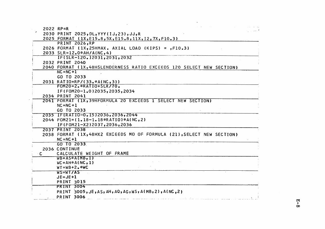
CALL EXIT 3004 FORMAT (1X,71HPROB.NO. SPAN HEIGHT Q LOAD G FACTOR WT/UNIT SPAN
!MOMENT 8 MOMENT C ) 3005 FORMAT (2X,I3,F8.0,F7.0,F7.2,F9.2,Fl2.2,2F11.2) 3006 FORMAT ( lX ,69HWIND_L_Q_Q__LL_O_A_Q __ IHDR. BEAM THOR '~COL. MAX. AX WT.COL
lWT.BEAM TOTAL WT.) 3008 FORMAT (lX,F8.2,F7.0,F12.2,Fl0.2,F7.0,F8.0,2F9.0) 3015 FORMAT (1X,25HFIXED BASED PORTAL FRAMES)
END
t%1 I
\0
A PARTIAL LIST OF FORTRAN SYMBOLS
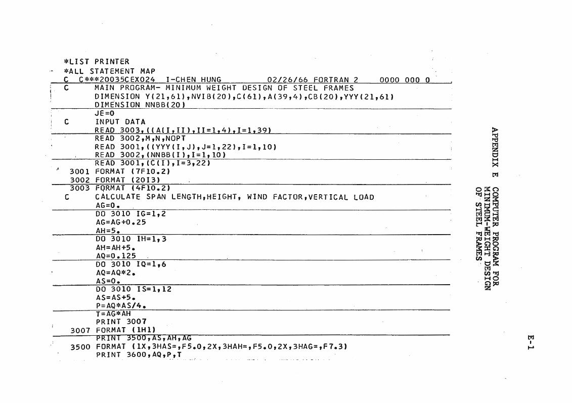
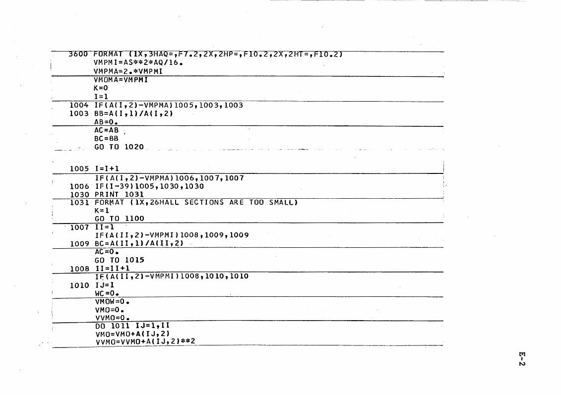
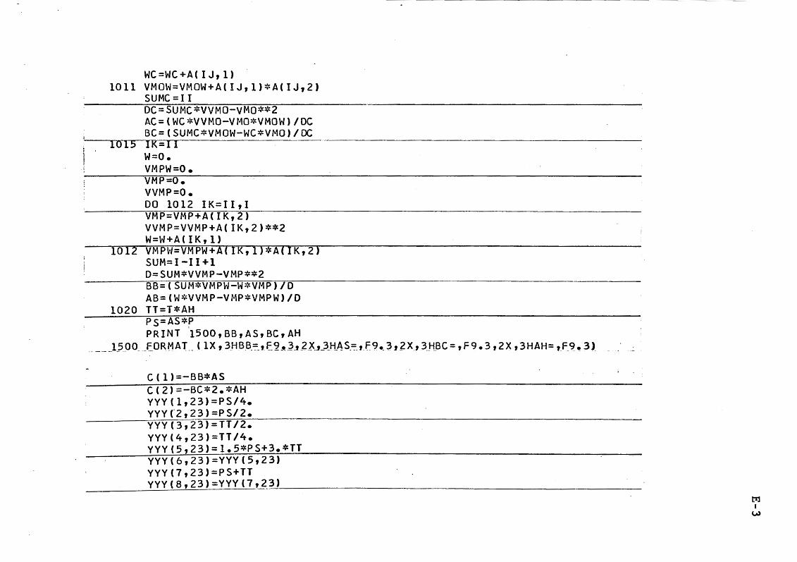
A = Properties of economic sections. M = Number of rows in the Augment Matrix. N = Number of columns in the Augment Matrix. YYY = Coefficients by rows in the Augment Matrix. NNBB = Read in vectors in basis for first table. C = Read in cost coefficients. AG = Wind load factor. AH = Height of frame. AQ = Uniform loading on frame AS = Span length of frame. VMPMI = Minimum plastic moment for bearn. VMPMA = Maximum plastic moment for bearn. VMOMI = Minimum plastic moment for column. VMOMA = Maximu111 plastic moment for colu:nn. BB = Slope of best fit straight line for weight
BC
Xl X2 R SLR WB we WT WS
per foot vs. Mp equation for beam. Slope of best fit straight line for weight per foot vs. Mp equation for column. Theoretical plastic moment for bea~.
= Theoretical plastic moment for column. Axial load in the column.
= Slenderness ratio. Weight of beam. Weight of column. Total weight of the frame. Frame weight per unit span length.
1:%:1 I
~ 0
t-e: N :~
~ ~ ~
AS= 20. AH= 10. AG= .250 AQ= .so P= 2.50 T= 2.50 BB= .239 AS= 20.000 BC= .292 AH= !OJOOO THE MAXIMUM VALUE OF Z IS -.13300198E+03 OPT INAJ__SO~UT IO_['J FOLLOW_$ ____________________________ _ VARIABLE VALUE