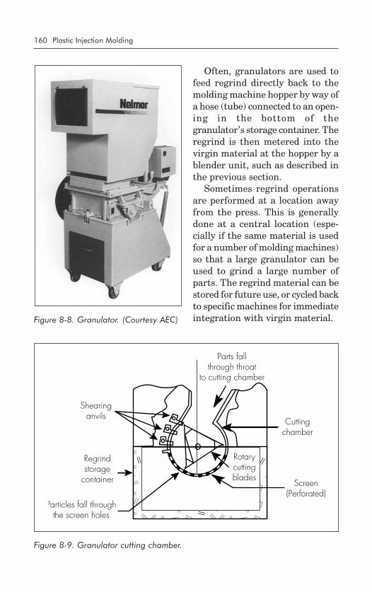
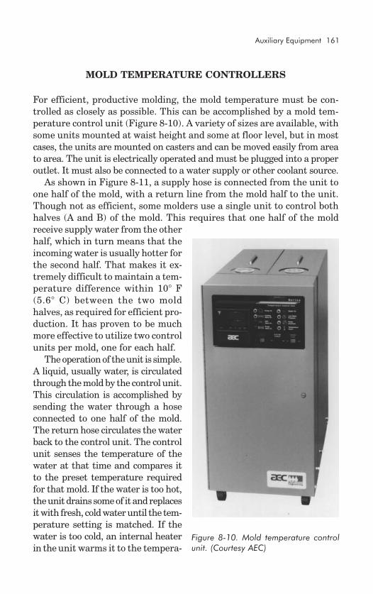
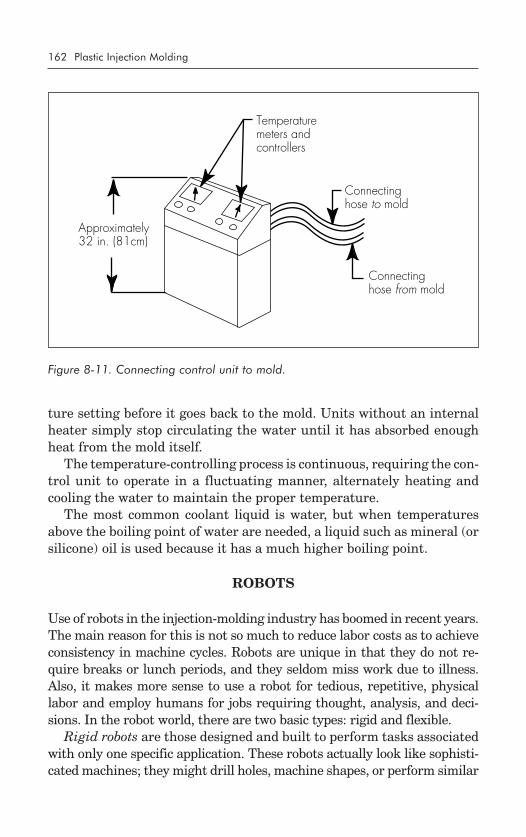
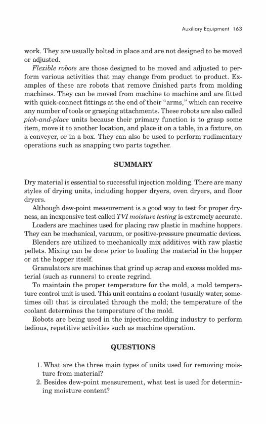
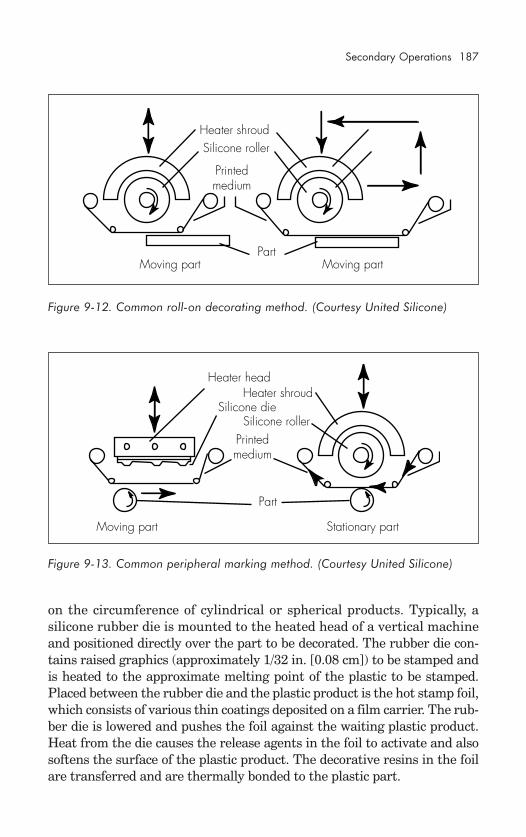
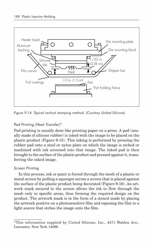
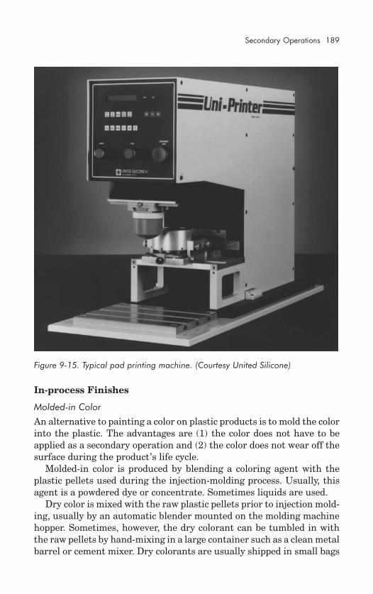
Plastic Injection Molding ...manufacturing process fundamentals By Douglas M. Bryce Volume I: Fundamentals of Injection Molding series Published by the Society of Manufacturing Engineers Dearborn, Michigan ®
Transcript
Plastic Injection Molding...manufacturing
processfundamentals
By Douglas M. Bryce
Volume I: Fundamentals ofInjection Molding series
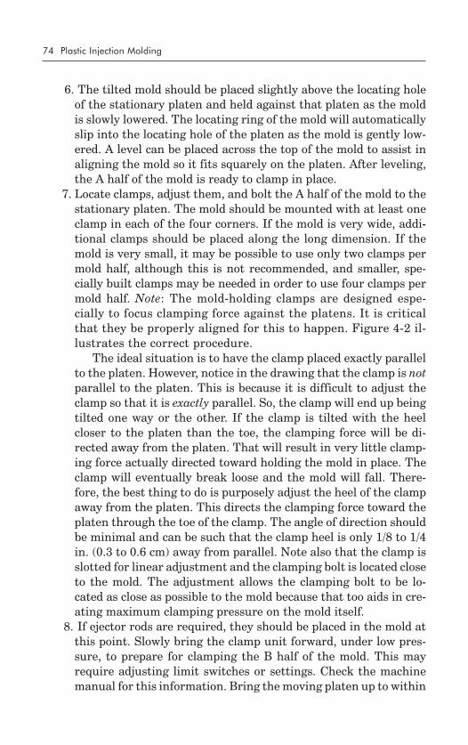
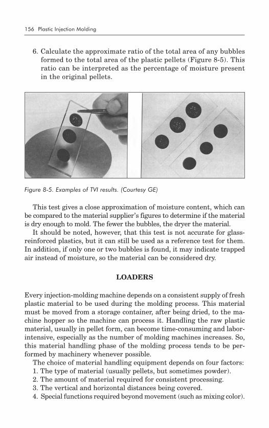
Published by theSociety of Manufacturing Engineers
All rights reserved, including those of translation. This book, or parts thereof,may not be reproduced in any form or by any means, including photocopy-ing, recording, or microfilming, or by any information storage and retrievalsystem, without permission in writing of the copyright owners.
No liability is assumed by the publisher with respect to the use of infor-mation contained herein. While every precaution has been taken in thepreparation of this book, the publisher assumes no responsibility for er-rors or omissions. Publication of any data in this book does not constitutea recommendation or endorsement of any patent, proprietary right, orproduct that may be involved.
Library of Congress Catalog Card Number: 96-067394International Standard Book Number: 0-87263-472-8
Additional copies may be obtained by contacting:
Society of Manufacturing EngineersCustomer ServiceOne SME DriveDearborn, Michigan 481211-800-733-4763
SME staff who participated in producing this book:
Donald A. Peterson, Senior EditorDorothy M. Wylo, Production AssistantRosemary K. Csizmadia, Operations AdministratorSandra J. Suggs, Editorial AssistantJerome T. Cook, Staff PhotographerKaren M. Wilhelm, Manager, Book PublishingCover design by Judy D. Munro, Manager, Graphic Services
Printed in the United States of America
Preface
This book (and accompanying volumes to follow) represents over threedecades of my involvement in the plastics industry, most of which wasspent in injection molding of thermoplastic materials. Through those years,it became apparent to me that most of the people in this industry hadlearned what they know by doing. Their skills were honed by makingmistakes, learning from those mistakes, and plunging forward to discoverother areas in which the learning process had to be repeated. While thismethod of attaining knowledge did work, I felt it would be better if nov-ices to the industry could be made aware of the basics before being ex-posed to the trials and tribulations that accompany typical seat-of-the-pantsaccumulation of knowledge.
Before deciding to write a book on the subject, I researched the avail-able literature and found it to be written, for the most part, for those al-ready in the industry who had a working knowledge of the day-to-dayroutines involved with injection molding. So, I decided to write a sourceof basic, fundamental information on injection molding for those who areinterested in getting a sound initial grasp of the subject and who alsowish to have a reference tool of charts, diagrams, and data that can beused for years to come. I believe this goal is accomplished in the publica-tion of this series.
I have structured the text as a guide to lead the reader through the en-tire injection molding process from its historic inception to the currentstate of the art. At the close of each chapter are questions pertinent tothe material of that chapter. Answers to the questions appear at theend of the book.
ACKNOWLEDGMENTS
This work could not have been done without the cooperation and involve-ment of many people. I wish to take this opportunity to thank the follow-ing for their contributions to the achievement of this goal:
• Society of Manufacturing Engineers for having the foresight and cour-age to publish the book(s).
• AEC, Incorporated, for the use of photographs and information con-cerning various pieces of equipment manufactured by them.
xxii
• Branson Ultrasonics, Incorporated, for the use of photographs andinformation concerning various pieces of equipment manufacturedby them.
• GE Plastics for the use of photographs and information concerningvarious plastics manufactured by them.
• Perkin-Elmer Corporation for the use of photographs and informa-tion concerning various pieces of equipment manufactured by them.
• Texas Plastic Technologies for allowing me the time and opportunityto write and research on the job.
• United Silicone, Incorporated, for the use of photographs and infor-mation concerning various pieces of equipment manufactured bythem.
I am especially grateful to my wife, my family, and my God for theencouragement and support they delivered during the time it took me towrite the book, and for putting up with my seemingly unlimited requestsand tremendous mood swings during that period.
Please accept this book as it is intended, and I welcome you to the worldof plastics. Here’s hoping your involvement in the injection-molding in-dustry will be as rewarding as mine has been.
How It All Began ........................................................................ 1Evolution of the Screw................................................................. 1Industry Evolution ....................................................................... 2A Vision of Tomorrow ................................................................. 3
The Main Components .............................................................. 11The Injection Unit ................................................................ 11
Sizing the Injection Unit/Purpose of the Injection Unit/The Heating Cylinder/The Basic Hopper/The InjectionScrew/Injection Screw Designs/Screw Tip and CheckRing/Nonreturn Valves and Ball Shutoffs/The Nozzle
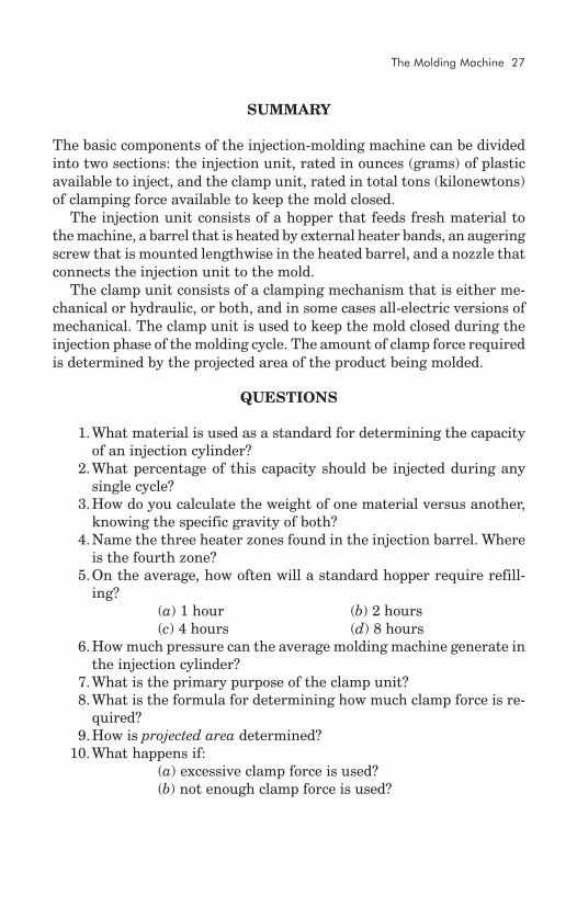
The Clamp Unit .................................................................. 21Sizing the Clamp Unit/How Much Force Is Required?/Determining Projected Area/What About That DDimension?/What Happens If Too Little Clamp ForceIs Used?/What Happens If Too Much Clamp Force Is Used?
Identifying the Parameters ......................................................... 29Temperature ............................................................................. 30
Melt Temperature Control .................................................... 30Insulation Blankets
Mold Temperature Control ................................................... 33Postmold Shrinkage Control
Hydraulic System Temperature Control .................................. 35Ambient Temperature Control ............................................... 35Insulation Sheets ................................................................. 36
Pressure .................................................................................. 37Injection Unit ...................................................................... 37
Clamp Unit ........................................................................ 39Hydraulic Clamp System/Mechanical Clamp(Toggle) System
How Much Pressure Is Needed? .......................................... 42Time ........................................................................................ 44
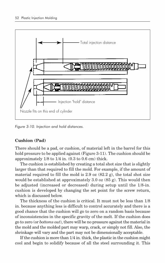
Gate-to-gate Cycle Time ...................................................... 44Gate Close Time ................................................................. 44Mold Close Time ................................................................ 45Initial Injection Time ............................................................ 46Injection Hold Time ............................................................. 46Cooling Time ..................................................................... 47Screw Return Time .............................................................. 47Mold Open Time ................................................................ 48Ejection Time...................................................................... 49Part-removal Time ............................................................... 49Mold-inspection Time .......................................................... 49
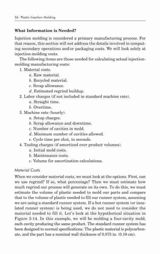
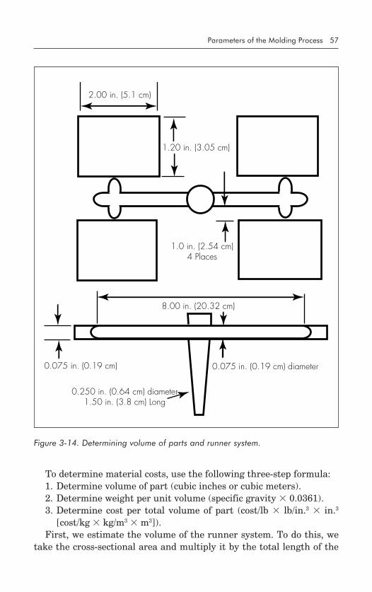
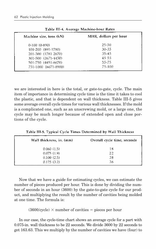
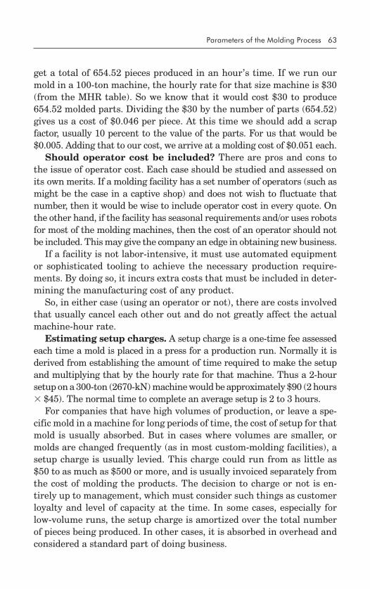
Determining Injection-molding Costs ........................................... 55What Information Is Needed? .............................................. 56
Material Costs/Labor Costs/Machine Costs/Tooling Costs
Adding It All Up ................................................................. 64
The Need for Control ................................................................ 67Part Quality ....................................................................... 67Part Cost ........................................................................... 68Parameter Effects ................................................................ 69
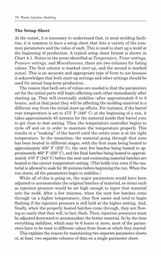
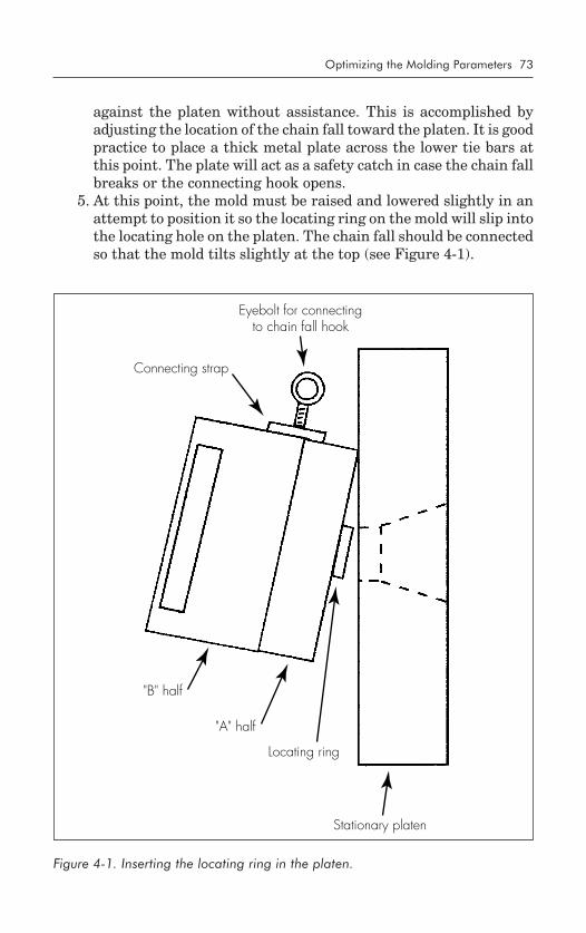
What Are the Proper Parameter Values? ..................................... 69The Setup Sheet .................................................................. 70Installing and Setting up the Mold ........................................ 72
Sizing and Inspection/Installation ProcedureOptimizing Temperature ............................................................ 78
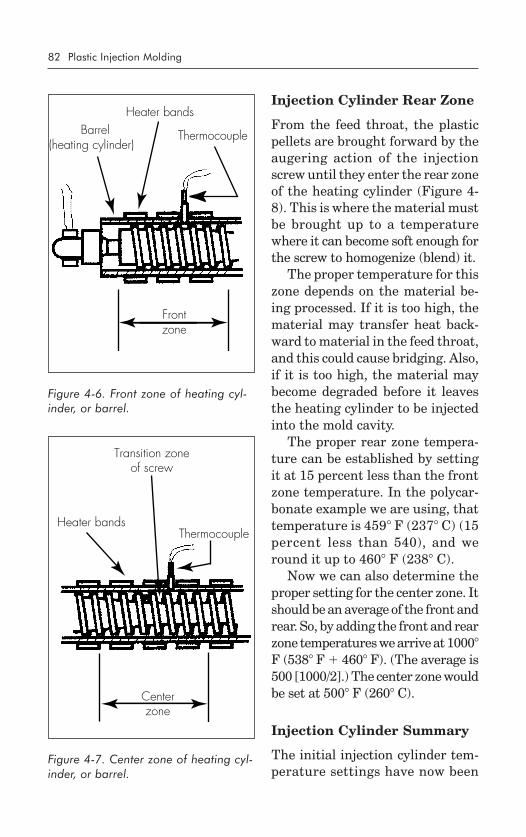
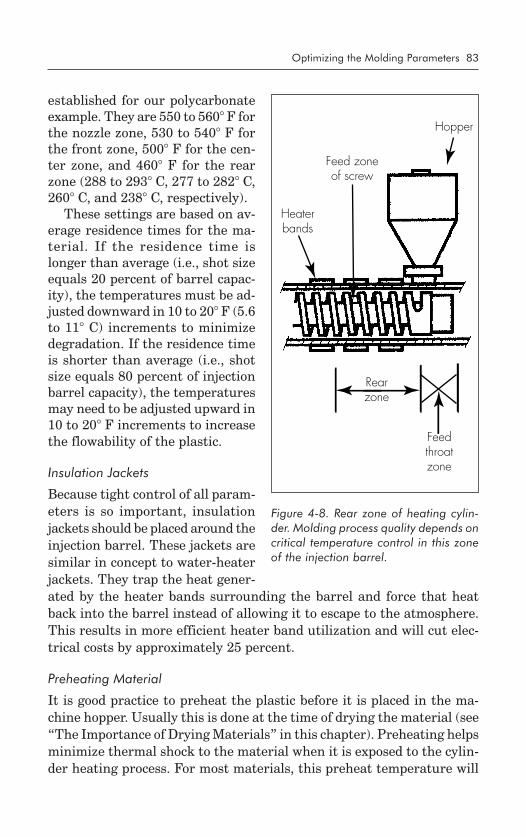
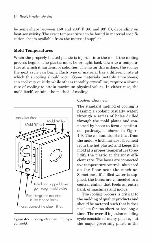
Checking Temperature of MeltInjection Cylinder Front Zone ............................................... 81Injection Cylinder Center Zone ............................................ 81Injection Cylinder Rear Zone ............................................... 82Injection Cylinder Summary ................................................. 82
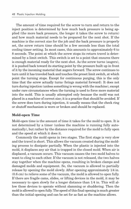
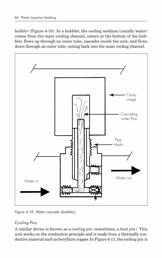
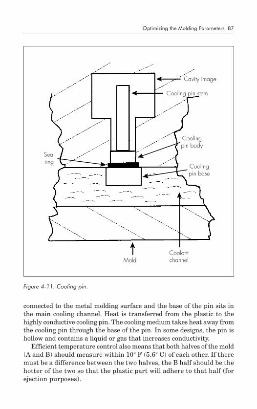
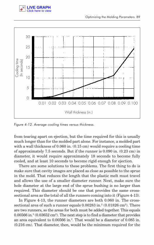
Cooling Channels/Cascades (Bubblers)/Cooling Pins/Insulation Sheets/Cooling Related to Cycle Times/CoolingRelated to Standard Runners/Cooling Related toHot Runners
Machine and Oil Temperatures ............................................ 92Purpose of Heat Exchanger
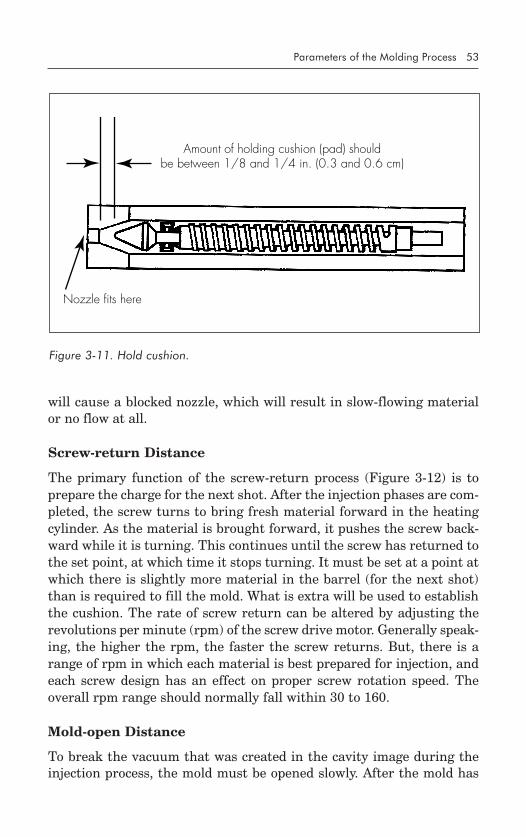
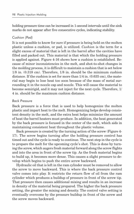
Injection Unit ...................................................................... 94Developing Injection Pressure/How Much InjectionPressure Is Required?/Initial Injection Pressure andTime/Holding Pressure and Time/Cushion (Pad)/Back Pressure/Decompression
Clamp Unit ...................................................................... 101Purpose of Clamp Pressure/How Much ClampPressure Is Required?
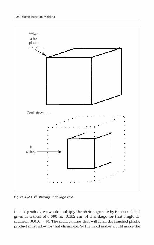
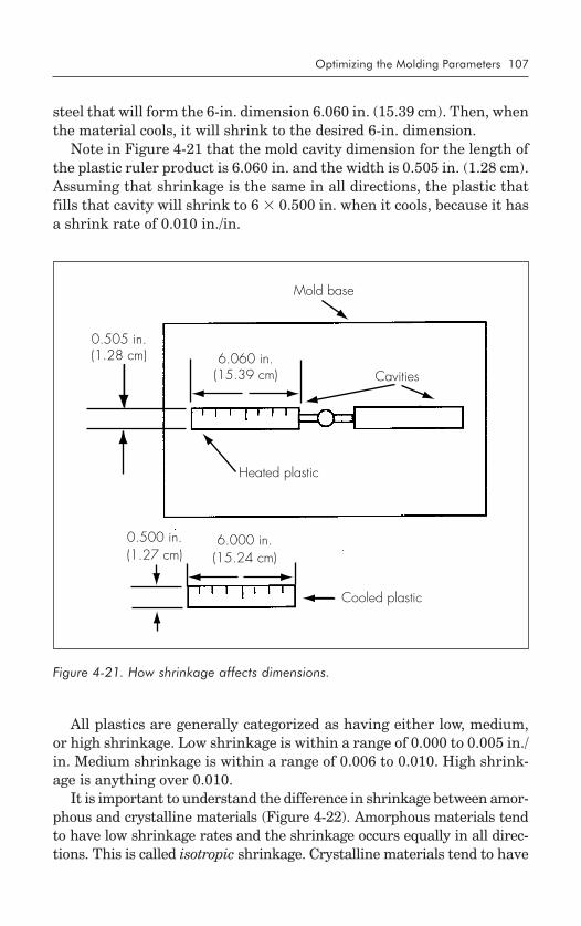
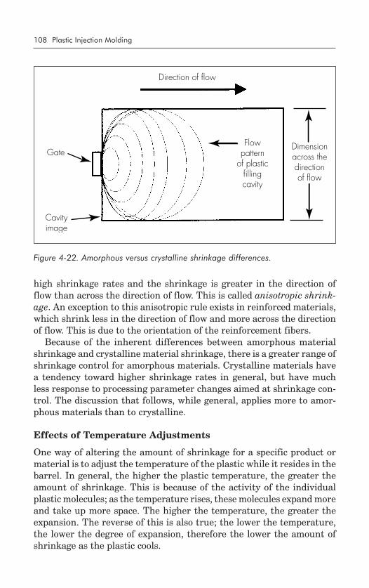
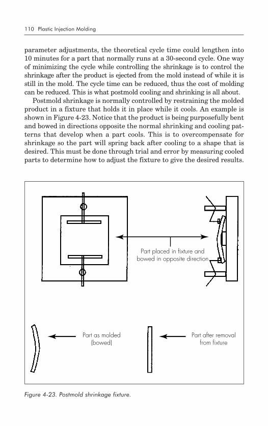
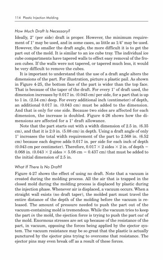
Controlling Shrinkage ............................................................. 105What Is Meant by Shrinkage? ........................................... 105Effects of Temperature Adjustments ..................................... 108Effects of Pressure Adjustments ........................................... 109Postmold Shrinkage .......................................................... 109
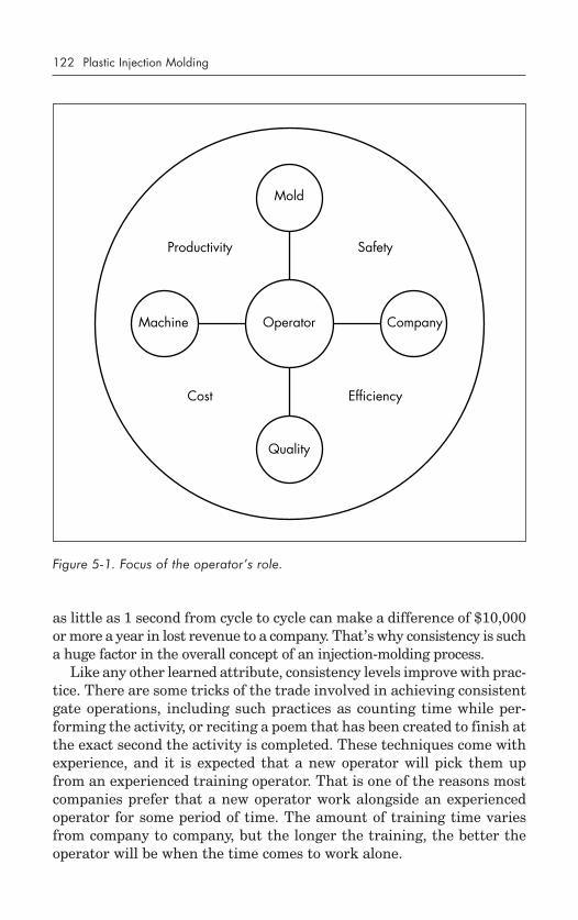
Focus of the Operator’s Role .................................................... 121Consistency ..................................................................... 121Inspection of Parts ............................................................ 123Inspection of the Mold ...................................................... 123Inspection of the Machine ................................................. 124
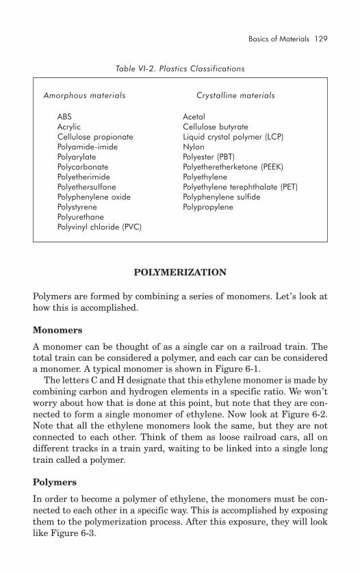
The Importance of Proper Material Selection ............................. 127Plastic Defined ....................................................................... 127Amorphous versus Crystalline .................................................. 128
Amorphous Materials ........................................................ 128Crystalline Materials ......................................................... 128Comparison of Amorphous and Crystalline ......................... 128
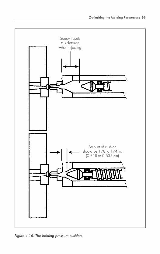
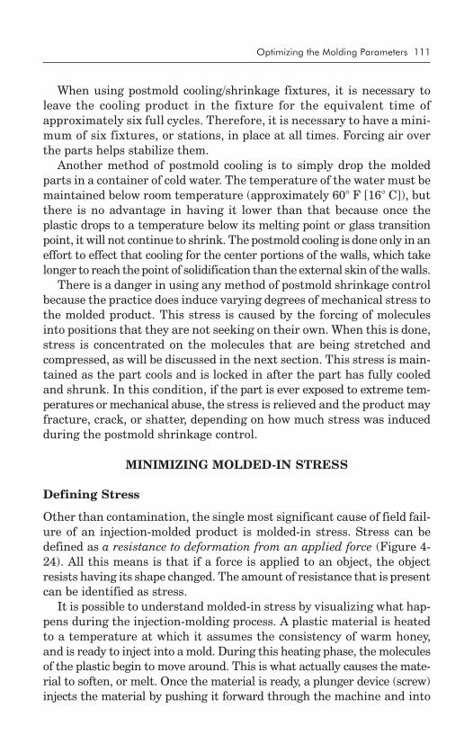
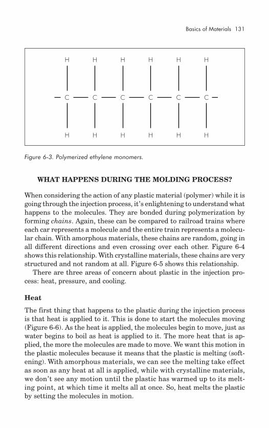
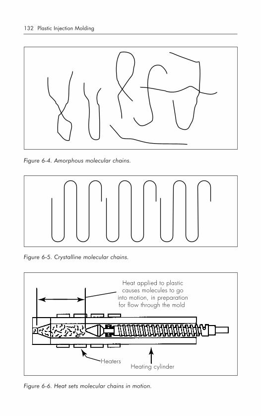
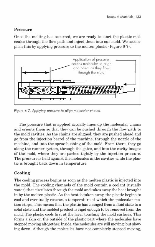
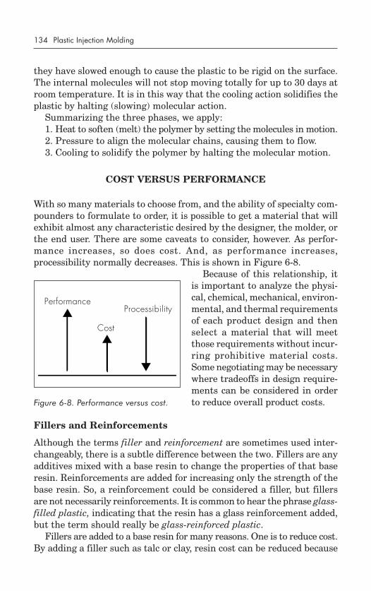
What Happens During the Molding Process? ............................ 131Heat ................................................................................ 131Pressure ........................................................................... 133Cooling ........................................................................... 133
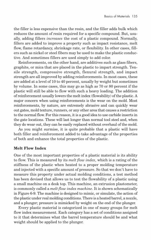
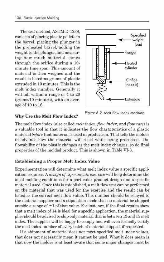
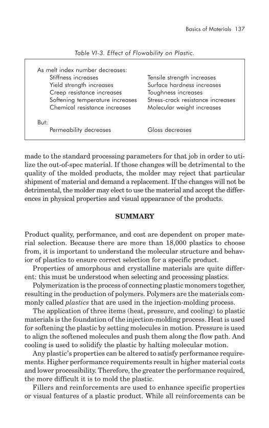
Cost versus Performance ......................................................... 134Fillers and Reinforcements ................................................. 134Melt Flow Index ................................................................ 135Why Use the Melt Flow Index? .......................................... 136Establishing a Proper Melt Index Value ............................... 136
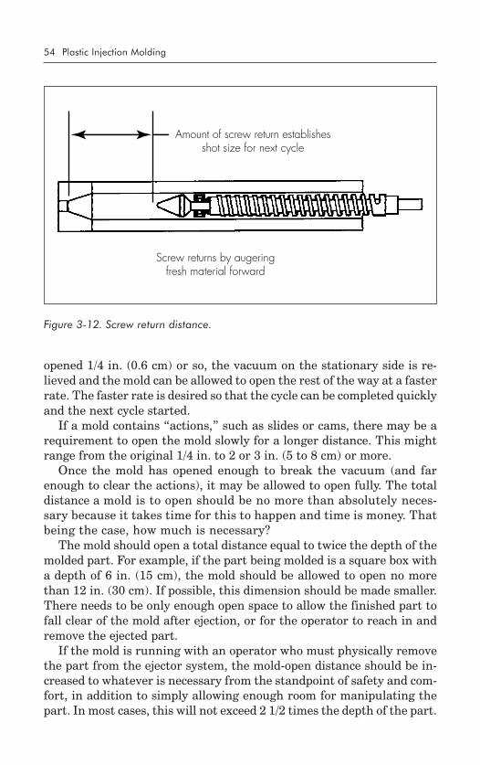
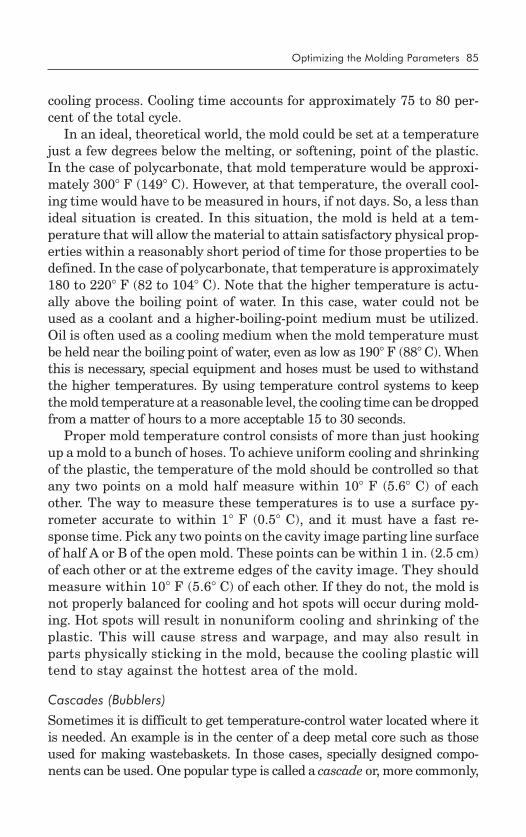
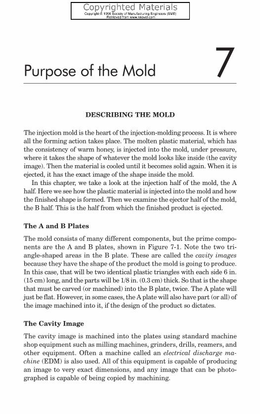
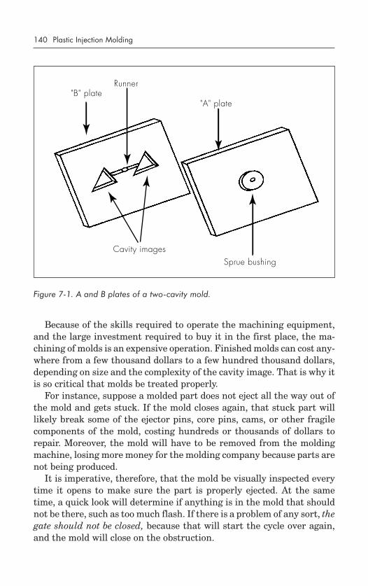
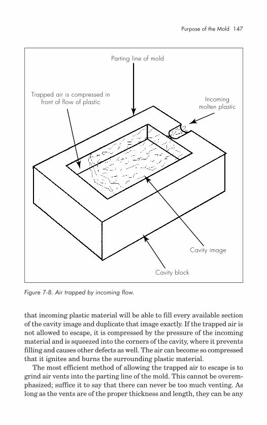
Describing the Mold ............................................................... 139The A and B Plates ........................................................... 139The Cavity Image ............................................................. 139
The Injection Half of the Mold .................................................. 141The Sprue Bushing ............................................................ 141Runners ........................................................................... 142Flash ............................................................................... 142
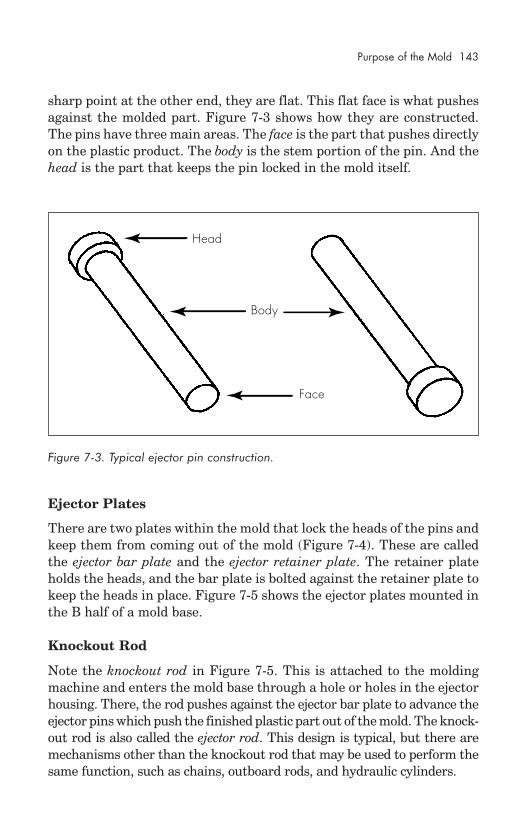
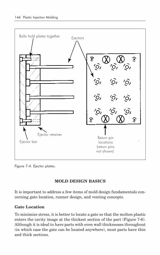
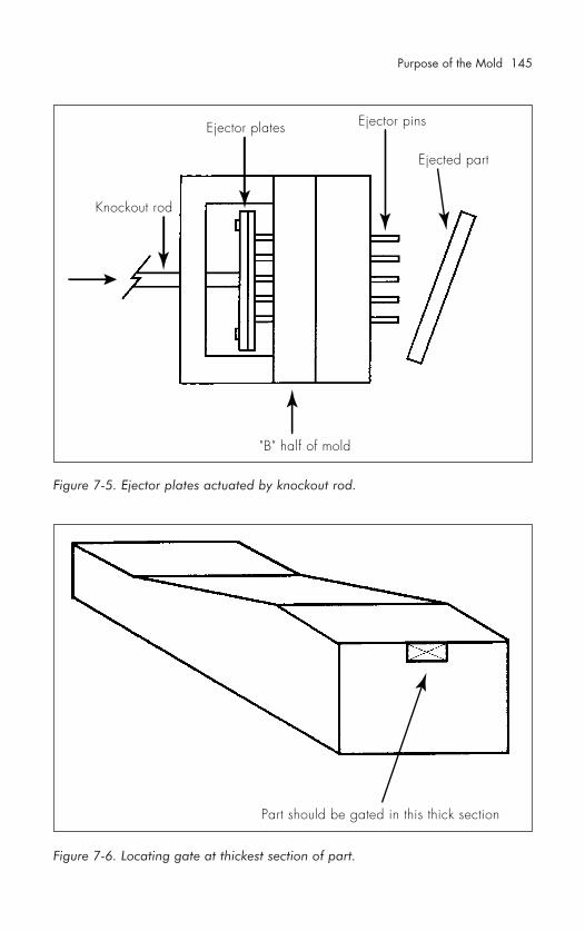
The Ejector Half of the Mold .................................................... 142Ejector Pins ...................................................................... 142Ejector Plates ................................................................... 143Knockout Rod ................................................................... 143
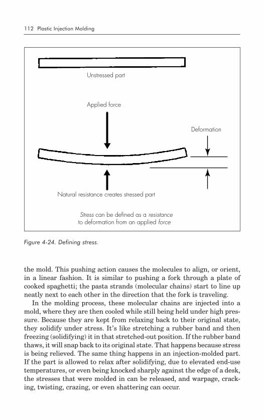
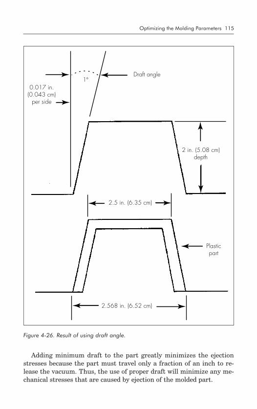
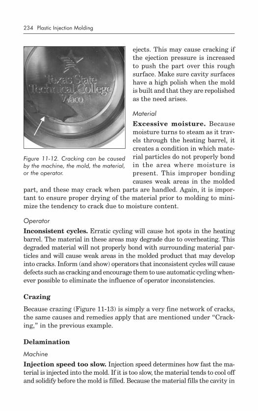
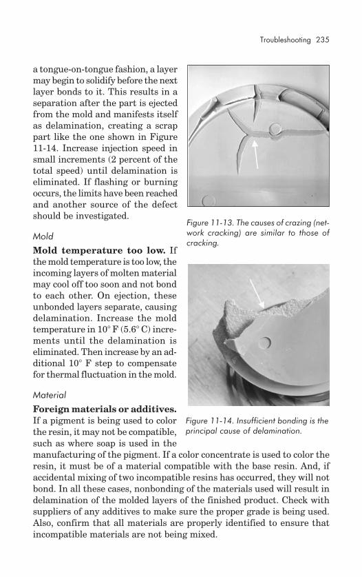
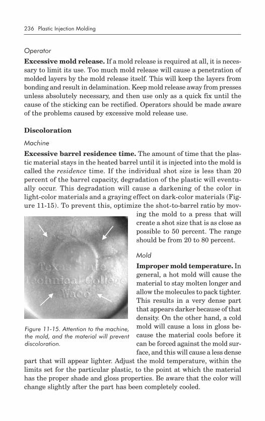
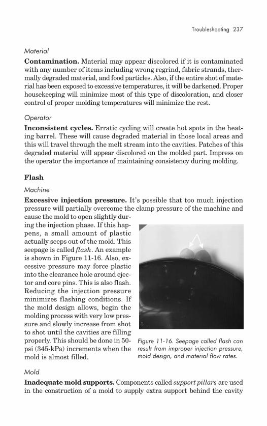
Troubleshooting Tips ............................................................... 249Rules to Mold By .................................................................... 250
In 1868, an enterprising young gentleman by the name of John WesleyHyatt developed a plastic material he called celluloid to enter in a contestcreated by a billiard ball manufacturer. The company was looking for anew material to substitute for ivory, which was becoming expensive anddifficult to obtain. Celluloid was actually invented in 1851 by AlexanderParkes, but Hyatt improved it so that it could be processed into finishedform. He created a celluloid billiard ball and won the contest’s grand prizeof $10,000, a rich sum in those days. Unfortunately, after the prize waswon, some billiard balls exploded on impact during a demonstration (dueto the instability and high flammability of celluloid) and further perfec-tion was required before it could be used in commercial ventures. But theplastics industry was born and began to flourish when Hyatt and hisbrother Isaiah patented the first injection-molding machine in 1872. Withthis machine, the brothers were able to mold celluloid plastic. Over thenext 40 to 50 years, others began to investigate this new process for manu-facturing such items as collar stays, buttons, and hair combs. By 1920, theinjection-molding industry had set its foundation, and it has been build-ing ever since.
During the 1940s, the plastic injection-molding industry exploded witha bang (not because of the instability of celluloid) as World War II createda demand for inexpensive, mass-produced products. New materials wereinvented for the process on a regular basis and technical advances resultedin more and more successful applications.
EVOLUTION OF THE SCREW
The machine that the Hyatt brothers invented was primitive, but performedwell for their purposes. It was simple in that it acted like a large hypoder-mic needle and contained a basic plunger to inject the plastic through aheated cylinder into a mold. In 1946, James Hendry began marketing hisrecently patented screw injection machine. This auger design replaced theconventional Hyatt plunger device and revolutionized the processing of
1
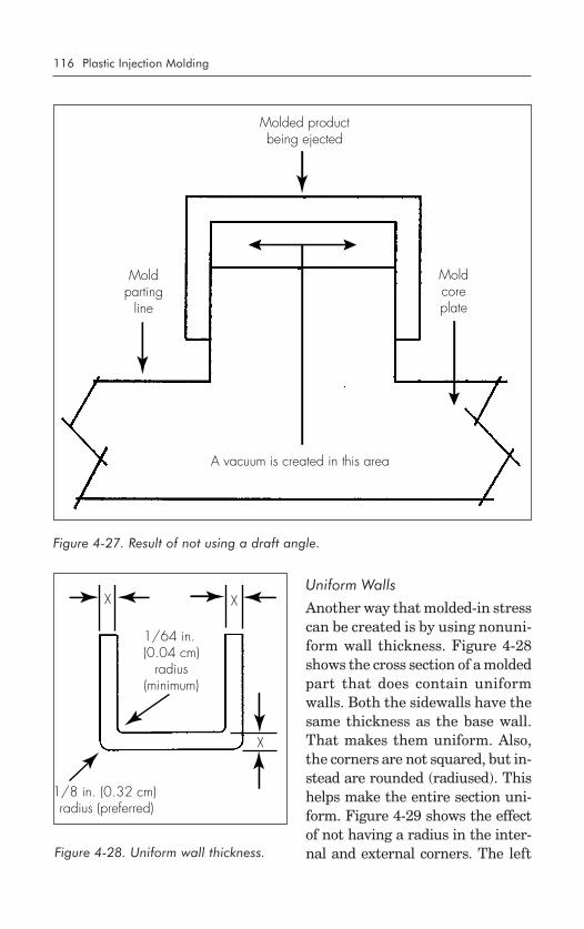
2 Plastic Injection Molding
plastics. Screw machines now account for approximately 95 percent of allinjection machines.
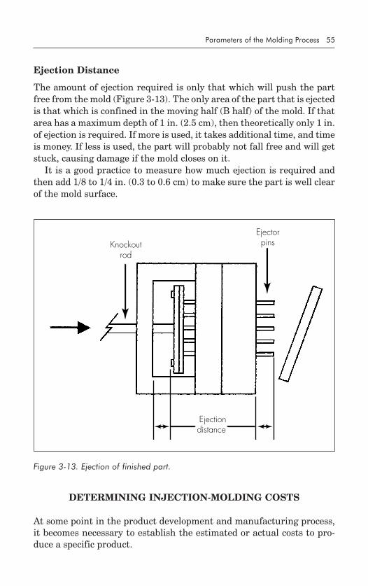
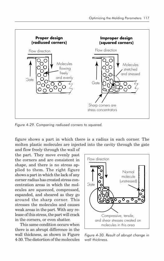
The auger design of the screw creates a mixing action in material beingreadied for injection. The screw is inside the heating cylinder and, whenactivated, mixes the plastic well, creating a homogenized blend of mate-rial. This is especially useful when colors are being added or when regrind(recycled material) is being mixed with virgin material. After mixing, thescrew stops turning and the entire screw pushes forward, acting like aplunger to inject material into the mold.
Another advantage of the screw is reduced energy requirements. As ina plunger machine, the cylinder that holds the plastic for injection has aseries of electrical heater bands around the outside. When energized, thesebands heat up and soften the plastic. However, the screw creates frictionwhen it turns within the cylinder and thus generates additional heat. There-fore, the material is also heated from the inside, and less heat is requiredfrom the electrical heater bands to soften the plastic.
Although the screw machine is by far the most popular, there is still aplace for the plunger-type machine. A plunger does not rotate. It simplypushes material ahead, then retracts for the next cycle. It, too, resides withina heated cylinder. Because there is no rotating, there is no shearing or mix-ing action. So, in a plunger machine, heat is provided solely by the exter-nal heater bands because there is no friction from the plunger as there isfrom a screw. If two different colored materials are placed in the heatedcylinder, they are not blended together. The plunger simply injects thematerials at the same time. If the two colors are, for instance, white andblack, the resulting molded part will take on a marbled appearance withswirls of black and white. This may be the desired finish for certain prod-ucts, such as lamp bases or furniture, and the plunger machine allowsthat finish to be molded into the product. Use of a screw machine wouldresult in a single-color (gray) product being molded because the two col-ors would be well mixed prior to injection.
INDUSTRY EVOLUTION
From its birth in the late 1800s to the present time, the injection-moldingindustry has grown at a fast and steady rate. It has evolved from produc-ing combs and buttons to molding products for varied industries, includ-ing automotive, medical, aerospace, consumer, toys, plumbing, packaging,and construction.
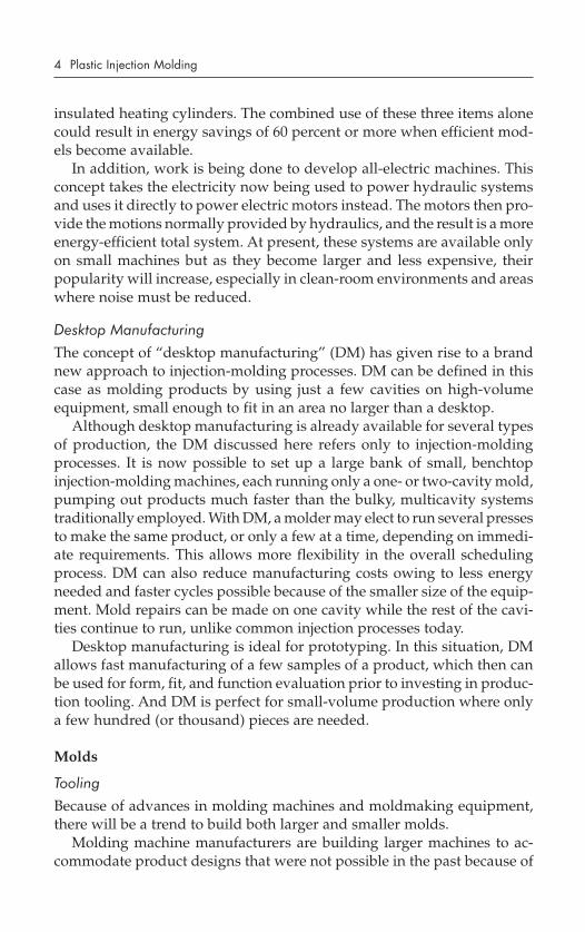
Table I-1 lists some of the important dates in the evolution of the injec-tion-molding industry.
Overview of the Industry 3
A VISION OF TOMORROW
The future will see some major changes in the way injection-molding com-panies operate. In particular, changes will take place in four principal ar-eas: processes, materials, molds (tooling), and business concepts.
Processes
Energy Efficiency
Energy-efficient machines will be developed to better utilize available re-sources. At present, injection-molding machines use vast amounts of elec-tricity to heat the plastic, power the hydraulic pumps and motors, andcontrol the temperature of the molds. The cost of this energy is steadilyrising and the resources used to create the electricity are becoming morescarce and consequently more expensive. Thus, it is necessary to find waysto reduce the amount of energy required to produce products.
Some of the innovations being considered to reduce energy require-ments include internally heated injection screws, insulated molds, and
Table I-1. Evolution of Injection Molding
1868 John Wesley Hyatt injection-molds celluloid billiard balls.1872 John and Isaiah Hyatt patent the injection-molding machine.1937 Society of the Plastics Industry founded.1938 Dow invents polystyrene (still one of the most popular
materials).1940 World War II creates large demand for plastic products.1941 Society of Plastics Engineers founded.1942 DME introduces stock mold base components.1946 James Hendry builds first screw injection-molding machine.1955 General Electric begins marketing polycarbonate.1959 DuPont introduces acetal homopolymer.1969 Plastics land on the moon.1972 The first part-removal robot is installed on a molding machine.1979 Plastic production surpasses steel production.1980 Apple uses acrylonitrile-butadiene-styrene (ABS) in the Apple IIE
computer.1982 The JARVIK-7 plastic heart keeps Barney Clark alive.1985 Japanese firm introduces all-electric molding machine.1988 Recycling of plastic comes of age.1990 Aluminum mold introduced for production molding.1994 Cincinnati-Milacron sells first all-electric molding machine in
the U.S.
4 Plastic Injection Molding
insulated heating cylinders. The combined use of these three items alonecould result in energy savings of 60 percent or more when efficient mod-els become available.
In addition, work is being done to develop all-electric machines. Thisconcept takes the electricity now being used to power hydraulic systemsand uses it directly to power electric motors instead. The motors then pro-vide the motions normally provided by hydraulics, and the result is a moreenergy-efficient total system. At present, these systems are available onlyon small machines but as they become larger and less expensive, theirpopularity will increase, especially in clean-room environments and areaswhere noise must be reduced.
Desktop Manufacturing
The concept of “desktop manufacturing” (DM) has given rise to a brandnew approach to injection-molding processes. DM can be defined in thiscase as molding products by using just a few cavities on high-volumeequipment, small enough to fit in an area no larger than a desktop.
Although desktop manufacturing is already available for several typesof production, the DM discussed here refers only to injection-moldingprocesses. It is now possible to set up a large bank of small, benchtopinjection-molding machines, each running only a one- or two-cavity mold,pumping out products much faster than the bulky, multicavity systemstraditionally employed. With DM, a molder may elect to run several pressesto make the same product, or only a few at a time, depending on immedi-ate requirements. This allows more flexibility in the overall schedulingprocess. DM can also reduce manufacturing costs owing to less energyneeded and faster cycles possible because of the smaller size of the equip-ment. Mold repairs can be made on one cavity while the rest of the cavi-ties continue to run, unlike common injection processes today.
Desktop manufacturing is ideal for prototyping. In this situation, DMallows fast manufacturing of a few samples of a product, which then canbe used for form, fit, and function evaluation prior to investing in produc-tion tooling. And DM is perfect for small-volume production where onlya few hundred (or thousand) pieces are needed.
Molds
Tooling
Because of advances in molding machines and moldmaking equipment,there will be a trend to build both larger and smaller molds.
Molding machine manufacturers are building larger machines to ac-commodate product designs that were not possible in the past because of
Overview of the Industry 5
molding-machine size constraints. Products such as automotive fendersand wraparound bumpers will be molded on machines that are the size ofsmall houses. The more this is done, the more it will drive manufacturersto build larger and larger machines. Of course, every machine must havea mold. So the molds will be built larger and larger to accommodate prod-uct design requirements.
Conversely, advances in materials and processing systems have led tothe production of small parts that formerly were not candidates for injec-tion molding. Products such as miniature electronic connectors and tinymedical valves are now being designed. The tolerance requirements andsmall size of these components require extremely accurate, sophisticatedmolding machines; these are being built now in sizes that will fit on thetop of an ordinary desk. The machine tool manufacturers are striving tobuild even smaller machines as the demand increases. So, the molds forthese machines are also smaller and smaller. There are molds now thatcan fit in the palm of a human hand, and the trend is toward even smallermolds to accommodate future product requirements.
Lead Times
Lead time is defined as the total amount of time required to obtain a prod-uct, from purchase order to finished item. In other words, the lead timefor a mold extends from the moment a purchase order is received by themoldmaker to the moment the mold is delivered to the company orderingthe mold. A typical lead time today ranges from 12 to 16 weeks for anaverage mold. (This does not include time to debug the mold or try it outin a production environment.)
A lead time of 12 to 16 weeks may not seem like much to those whohave been in the business a while. In fact, it is a great improvement overwhat prevailed before. In earlier days, the lead time may have been 36weeks or longer. Nonetheless, in today’s competitive environment, leadtimes are critical because they dictate when a product can get to its mar-ket. The earlier the product can be introduced, the faster it can begin bring-ing in profits, and the quicker the company can begin investing those profitsin new product development.
There are numerous ways to minimize lead times, and many are beingpursued today. Certain of these promise to bring lead times down to un-heard-of numbers:
• Computer-generated data. Computers allow moldmakers and prod-uct designers to work closely together even if they are in differentcities, states, or countries. As computers become faster and more pow-erful, and as computer programs become more versatile, productdesigns can be generated and tested faster, and the same data can be
6 Plastic Injection Molding
used to make the molds. In fact, these things can be done as parallelefforts so the mold can be started before the product design is evenfinished.
• Mold materials. The common practice has been to use high-gradetool steels to build the cavities of the injection mold. However, newalloys and upgrades to present alloys are allowing molds to be builtfaster and weigh less. One material that will be used extensively isaluminum. Aluminum is now used primarily for prototype molds,but advances in the material alloys and acceptance by moldmakershas made it possible to use aluminum in many production mold cases.Beryllium copper, brass, soft steels, and even plastics such as ep-oxies are being used more and more in an effort to reduce lead timesfor making molds and thus get products into the marketplace faster.
The use of these materials and new computer equipment and programscan drastically reduce lead times. In some cases, lead times have beenreduced from the average 12 to 16 weeks to only 7 days. And the technol-ogy will soon be available to bring it down to only a few hours.
Materials
Advances in plastic materials have been profound. In 1995, there wereapproximately 18,000 different materials available for molding. These areincreasing at an average rate of 750 per year. The majority of availablematerials are alloys or blends of previously developed materials, and aproduct designer will probably be able to choose from them a materialthat provides exactly the right properties for a specific requirement. Again,computers come into play because the designer cannot possibly readthrough the property values of all those materials in a reasonable amountof time. The computer can do it in a few seconds and will list the materialsthat meet whatever criteria the designer requires. Then the designer canmake a choice from only a few materials rather than 18,000. But even if anexact material match does not exist, the designer will be able to call on acompounder to put together a material that does exactly match the re-quirements. Of course, that adds another material to the list of 18,000, andthat’s how the list evolved in the first place.
Recycling
Recycling will continue to be a major issue in the future, as it is today.Consumer acceptance of products made of recycled materials will increase,making it more profitable for companies to develop such products. Tech-nological advances will make it easy to separate discarded plastic prod-ucts so they may be properly recycled. Advances in machinery and material
Overview of the Industry 7
additives will allow mingled plastics (that cannot be separated) to be usedin products such as parking lot bumpers, picnic tables/benches, and wa-ter-sport products such as boating docks. Some of these products are avail-able today, but with future advances, they can be sold at more competitiveprices, and their availability and use will grow. Products will be designedwith recycling in mind so they may be easily dismantled and identifiedfor material content.
Business Concepts
Education and Training
As more and more companies downsize to become more efficient, em-ployees find that they are being required to perform work in areas thatthey may not be familiar with. Consider the purchasing agent who nowactually needs to be involved with the initial selection of plastic materialand press operators who must perform quality control activities as part oftheir machine operation responsibilities.
Companies are more aware that it is beneficial to train employees asmuch as possible and encourage them to take advantage of in-house aswell as off-site training and seminars. In the future, these activities willbecome more prevalent as employees will be expected to cross-train andtake on more and more responsibilities even as a condition of employ-ment. More emphasis will be placed on specialized education, and plas-tics courses will become more available at colleges and universities, to thepoint that one may earn a bachelor’s degree, and even a master’s degree,in plastics engineering.
Alliances
An alliance might be defined as combining talents, resources, or expertisein an attempt to make the allying parties more efficient and productive intheir respective efforts. For instance, a large computer company may findit beneficial to form an alliance with a small (or medium-sized) circuitboard manufacturer. The alliance gives the computer company access tocircuit board manufacturing technology, and gives the circuit board com-pany the security and financial resources of the computer company. Analliance creates benefits for both parties.
In the future, alliances will become extremely popular as large compa-nies move to reduce their own assets and personnel levels, and smallercompanies seek the resources available from large companies with mini-mum expenditure on their own part. The result will be an increase in thenumber of medium-sized companies resulting from expansion ofsmaller companies and a decrease in the number of large companies as
8 Plastic Injection Molding
a result of downsizing. This will produce increased sharing of tech-nologies and information between allied companies and between groupsof specific industries.
Quality
The forming of alliances, coupled with the need to become globally ac-cepted, will drive companies of all sizes to improve their quality systems.The demand for products on a worldwide basis will require that compa-nies submit to, and accept, global quality control standards and proce-dures. The 1990s saw the beginnings of such programs with the advent ofISO 9000 activities and the concept of World Class. While these are sepa-rate programs, they are similar in the results they achieve, notably thatany company that meets the requirements of one will basically satisfy therequirements of the other. By meeting these requirements, a company willbe able to produce a product or provide a service for any other company,regardless of where it is located geographically, without the tedious, time-consuming qualification procedures that are now expected. And, if a com-pany is certified through ISO 9000 (or another global quality strategyprogram), it will automatically be certified to do business with any othercompany registered under the standard.
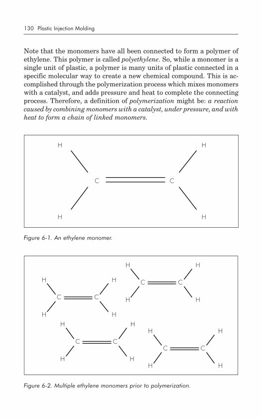
SUMMARY
John Wesley Hyatt launched the injection-molding industry in 1868 bywinning a contest to find a substitute for ivory in making billiard balls.
• The first injection-molding machine was formally patented in 1872by John and Isaiah Hyatt.
• With the advent of World War II, the plastic injection-molding in-dustry burgeoned because of the need for inexpensive, mass-pro-duced products.
• In 1946, John Hendry received a patent for his screw-style injection-molding machine. This revolutionized the industry and allowedfaster cycles, evenly distributed heat, and lower energy costs, whileproviding a material melt that was homogeneous.
• The future of the injection-molding industry will bring improvedmaterials, energy- efficient processes, increased use of desktop manu-facturing, larger and smaller tooling, much shorter lead times anddevelopment cycles, greater use of computer programs, increasedacceptance of recycling practices, greater emphasis on education andtraining, an increase in the concept of forming business alliances,and improved quality under World Class and ISO 9000 certificationprograms.
Overview of the Industry 9
QUESTIONS
1. What prompted the birth of the plastic injection-molding industry?2. Who was responsible for inventing the first injection-molding ma-
chine, and when?3. Who invented the first screw-style injection-molding machine, and
when?4. What are some of the advantages of using a screw injection machine
over a plunger machine?5. What is the one major advantage to using a plunger-style machine?6. What is the definition of desktop manufacturing?7. How many material choices were available in 1995?
(A) 180 (C) 18,000(B) 1,800 (D) 180,000
8. As a business concept, what is the definition of the term alliance?
The Molding Machine
THE MAIN COMPONENTS
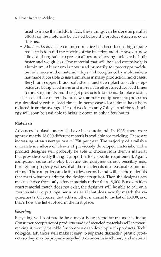
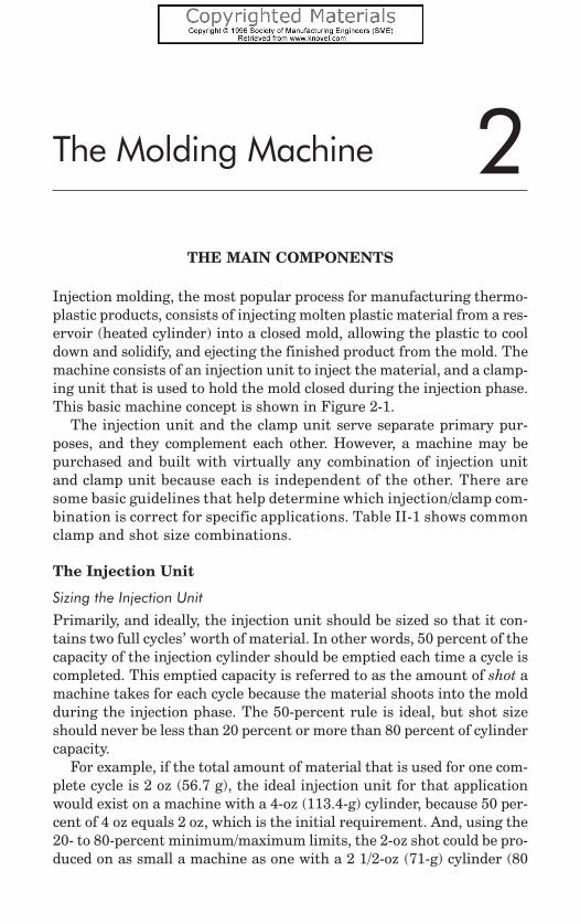
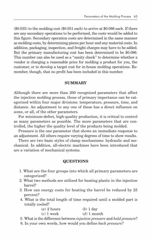
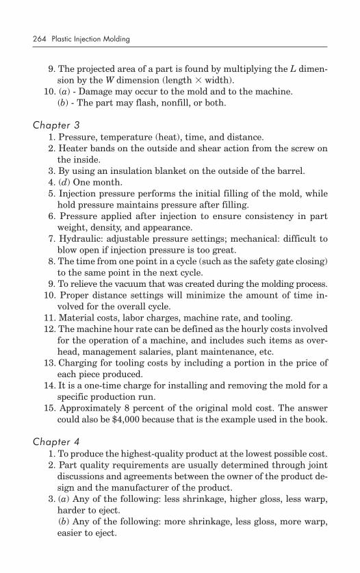
Injection molding, the most popular process for manufacturing thermo-plastic products, consists of injecting molten plastic material from a res-ervoir (heated cylinder) into a closed mold, allowing the plastic to cooldown and solidify, and ejecting the finished product from the mold. Themachine consists of an injection unit to inject the material, and a clamp-ing unit that is used to hold the mold closed during the injection phase.This basic machine concept is shown in Figure 2-1.
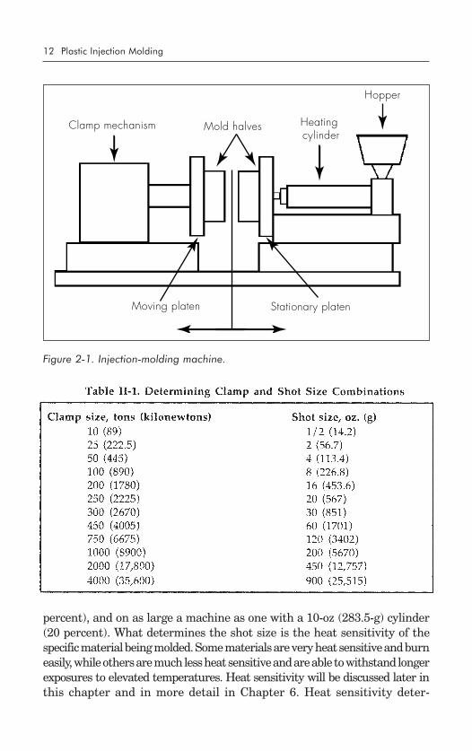
The injection unit and the clamp unit serve separate primary pur-poses, and they complement each other. However, a machine may bepurchased and built with virtually any combination of injection unitand clamp unit because each is independent of the other. There aresome basic guidelines that help determine which injection/clamp com-bination is correct for specific applications. Table II-1 shows commonclamp and shot size combinations.
The Injection Unit
Sizing the Injection Unit
Primarily, and ideally, the injection unit should be sized so that it con-tains two full cycles’ worth of material. In other words, 50 percent of thecapacity of the injection cylinder should be emptied each time a cycle iscompleted. This emptied capacity is referred to as the amount of shot amachine takes for each cycle because the material shoots into the moldduring the injection phase. The 50-percent rule is ideal, but shot sizeshould never be less than 20 percent or more than 80 percent of cylindercapacity.
For example, if the total amount of material that is used for one com-plete cycle is 2 oz (56.7 g), the ideal injection unit for that applicationwould exist on a machine with a 4-oz (113.4-g) cylinder, because 50 per-cent of 4 oz equals 2 oz, which is the initial requirement. And, using the20- to 80-percent minimum/maximum limits, the 2-oz shot could be pro-duced on as small a machine as one with a 2 1/2-oz (71-g) cylinder (80
2
12 Plastic Injection Molding
percent), and on as large a machine as one with a 10-oz (283.5-g) cylinder(20 percent). What determines the shot size is the heat sensitivity of thespecific material being molded. Some materials are very heat sensitive and burneasily, while others are much less heat sensitive and are able to withstand longerexposures to elevated temperatures. Heat sensitivity will be discussed later inthis chapter and in more detail in Chapter 6. Heat sensitivity deter-
Figure 2-1. Injection-molding machine.
Clamp mechanism Mold halves
Hopper
Heatingcylinder
Moving platen Stationary platen
The Molding Machine 13
mines the amount of time the material is able to stay within the heatedinjection cylinder before it begins to degrade. Degraded material willnot produce quality products. The 50-percent rule of thumb noted ear-lier ensures that no material, regardless of its allowed residence time,will degrade while being molded. The 20-percent rule of thumb appliesto materials with low heat sensitivity, and the 80-percent rule applies tomaterials that are extremely heat sensitive.
Note that the capacity of an injection unit is rated in terms of theweight of polystyrene it can hold. A conversion is required to determinehow much of any other plastic it can hold, and this is done by comparingspecific gravity values. Specific gravity values are available from thematerial supplier and from many plastic encyclopedia sources. For in-stance, polystyrene has a published specific gravity value of 1.04. In thecase of polycarbonate, the specific gravity value is 1.20. Specific gravityis an indicator of weight, with the higher values indicating heavier ma-terials. The specific gravity (sg) value of the selected material (in thiscase, polycarbonate) is divided by the specific gravity value of polysty-rene to determine how much of the selected material can be held in thecylinder. For this example, the polycarbonate sg of 1.20 is divided bythe polystyrene sg of 1.04, giving a value of 1.15. This means that amachine capable of injecting 10 oz (283.5 g) of polystyrene could alsoinject 11.5 oz (326 g) of polycarbonate.
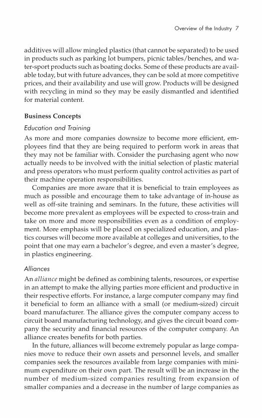
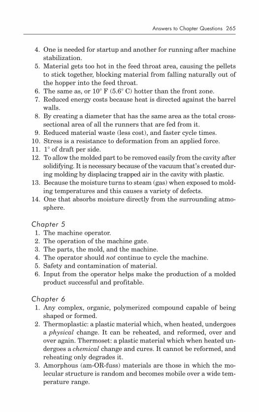
Purpose of the Injection Unit
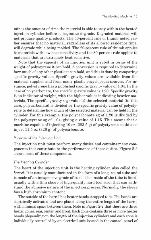
The injection unit must perform many duties and contains many com-ponents that contribute to the performance of these duties. Figure 2-2shows most of these components.
The Heating Cylinder
The heart of the injection unit is the heating cylinder, also called thebarrel. It is usually manufactured in the form of a long, round tube andis made of an inexpensive grade of steel. The inside of the tube is lined,usually with a thin sleeve of high-quality hard tool steel that can with-stand the abrasive nature of the injection process. Normally, the sleevehas a high chromium content.
The outside of the barrel has heater bands strapped to it. The bands areelectrically activated and are placed along the entire length of the barrelwith minimal space between them. Note in Figure 2-2 that there are threeheater zones: rear, center, and front. Each zone contains three or more heaterbands (depending on the length of the injection cylinder) and each zone isindividually controlled by an electrical unit located in the control panel of
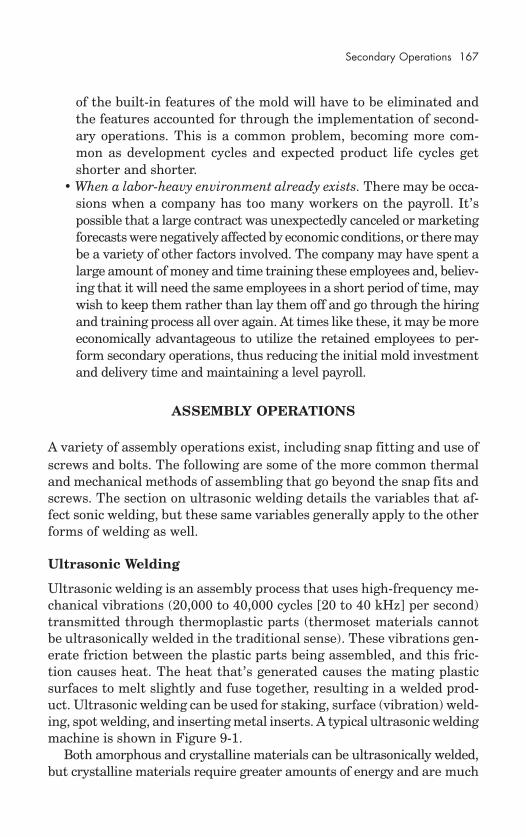
14 Plastic Injection Molding
the machine. Each temperature control unit is fed temperature infor-mation by a thermocouple in a hole in the wall of the heating barrel inthe area of the zone it is controlling. The control unit then decideswhether more heat is required and, if so, energizes the heater bands inthat zone. When the selected temperature is reached, the thermocoupleinforms the control unit, which stops sending electricity to the heaterbands until the temperature drops again, at which point the cycle repeats.
Minimum and maximum temperature limits are set on the controlunit and used by the unit to determine whether the heater bands shouldbe energized or de-energized. A single control unit and thermocoupleare assigned to a single heating zone, but there are three or more heat-ers in each zone, so each control unit actually controls three or moreheaters at the same time. Because all of the heaters in a single zone arewired together, whatever the control unit does to one heater it does toall of the heaters in that zone.
The Basic Hopper
In the upper right-hand section of Figure 2-2 is a component called thehopper. This is where raw plastic pellets are stored before they are intro-
Stationary platenHopper assembly
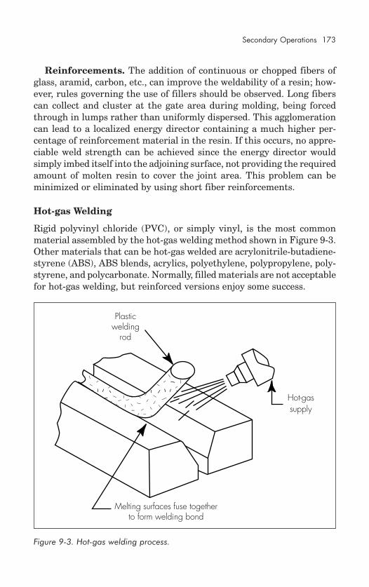
Heater bandsScrew
Openingfor
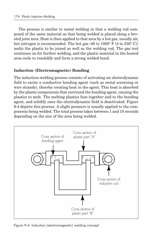
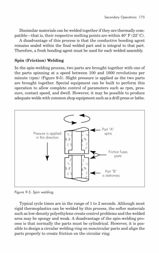
locatingring from
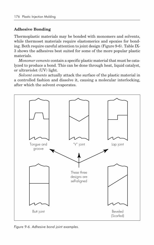
mold
Front Center Rear
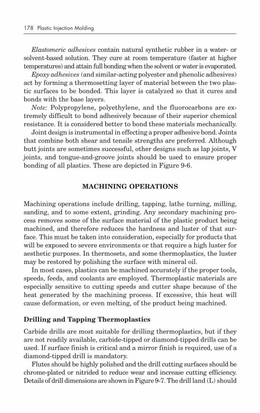
End capNozzle and tip
Barrel (Heating cylinder)
Screw motorMachine frame
Figure 2-2. Injection unit components.
The Molding Machine 15
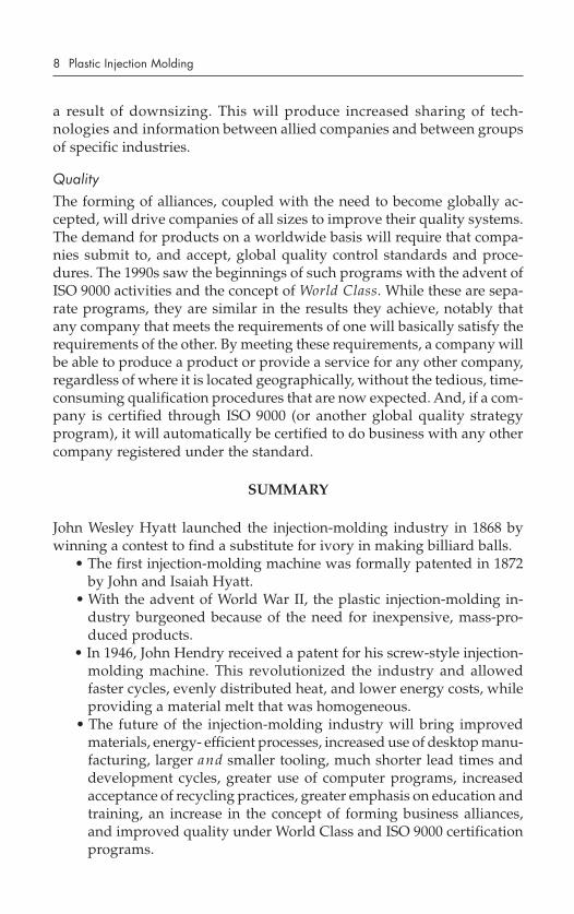
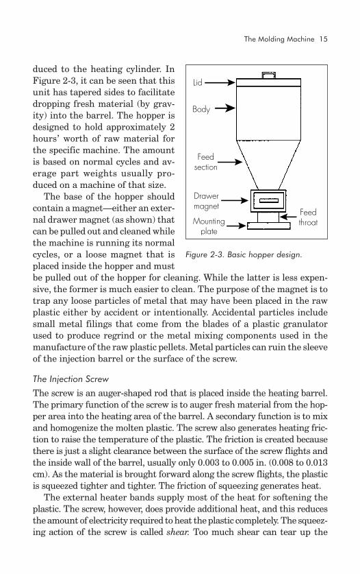
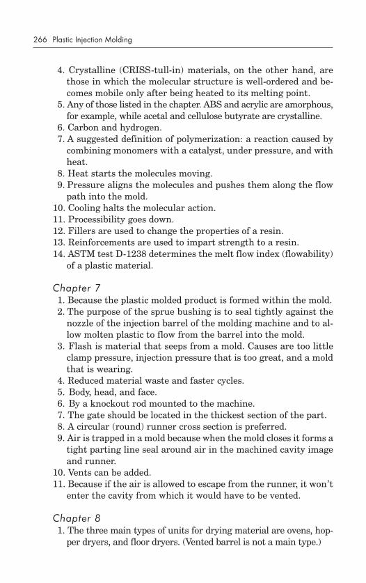
duced to the heating cylinder. InFigure 2-3, it can be seen that thisunit has tapered sides to facilitatedropping fresh material (by grav-ity) into the barrel. The hopper isdesigned to hold approximately 2hours’ worth of raw material forthe specific machine. The amountis based on normal cycles and av-erage part weights usually pro-duced on a machine of that size.
The base of the hopper shouldcontain a magnet—either an exter-nal drawer magnet (as shown) thatcan be pulled out and cleaned whilethe machine is running its normalcycles, or a loose magnet that isplaced inside the hopper and mustbe pulled out of the hopper for cleaning. While the latter is less expen-sive, the former is much easier to clean. The purpose of the magnet is totrap any loose particles of metal that may have been placed in the rawplastic either by accident or intentionally. Accidental particles includesmall metal filings that come from the blades of a plastic granulatorused to produce regrind or the metal mixing components used in themanufacture of the raw plastic pellets. Metal particles can ruin the sleeveof the injection barrel or the surface of the screw.
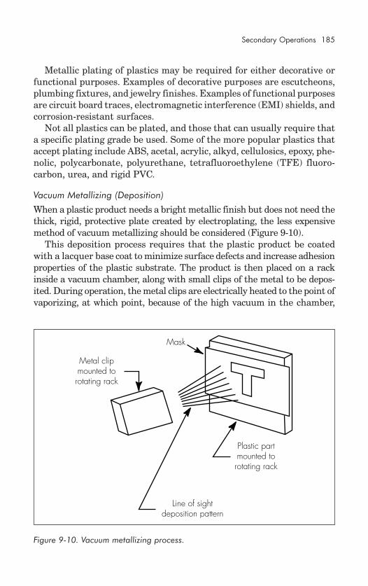
The Injection Screw
The screw is an auger-shaped rod that is placed inside the heating barrel.The primary function of the screw is to auger fresh material from the hop-per area into the heating area of the barrel. A secondary function is to mixand homogenize the molten plastic. The screw also generates heating fric-tion to raise the temperature of the plastic. The friction is created becausethere is just a slight clearance between the surface of the screw flights andthe inside wall of the barrel, usually only 0.003 to 0.005 in. (0.008 to 0.013cm). As the material is brought forward along the screw flights, the plasticis squeezed tighter and tighter. The friction of squeezing generates heat.
The external heater bands supply most of the heat for softening theplastic. The screw, however, does provide additional heat, and this reducesthe amount of electricity required to heat the plastic completely. The squeez-ing action of the screw is called shear. Too much shear can tear up the
Feedthroat
Lid
Body
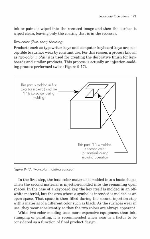
Feedsection
Drawermagnet
Mountingplate
Figure 2-3. Basic hopper design.
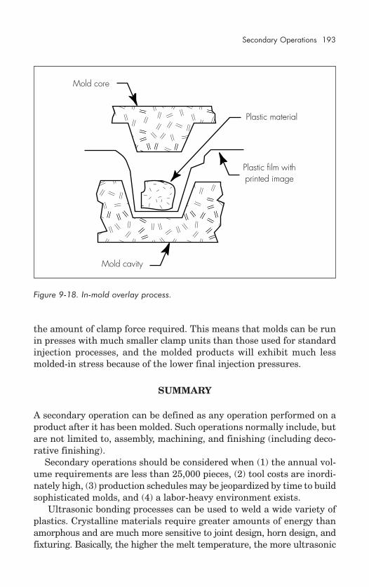
16 Plastic Injection Molding
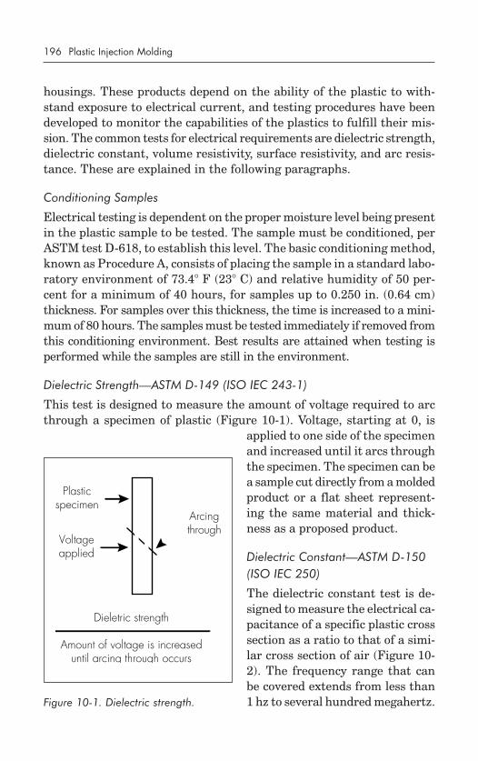
Screw tipmounts here
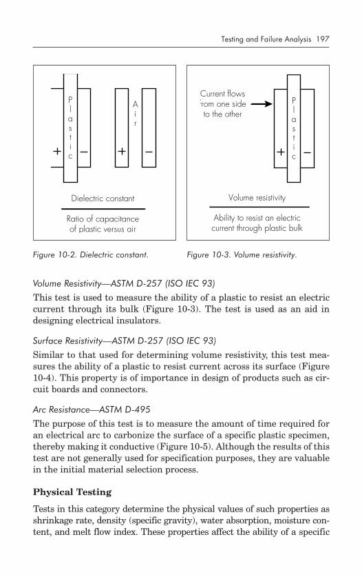
Screw flghtsMaterial flowsin this direction
This end connectsto screw motor
Screw diameter
Barrel liner
Sectionof barrelTypically 0.003 to 0.005 in.
(0.008 to 0.013 cm) clearancebetween barrel and screw
plastic molecules and degrade the material, making it inferior or evenuseless. For this reason, the screw itself cannot be used to impart all ofthe heat needed.
Injection Screw Designs
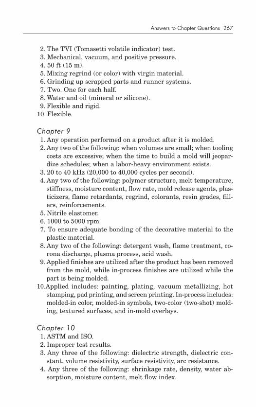
There are many different screw designs, with various shapes of flights,distances between flights, amounts of shearing action, screw tip geom-etries, and methods of shutoff.
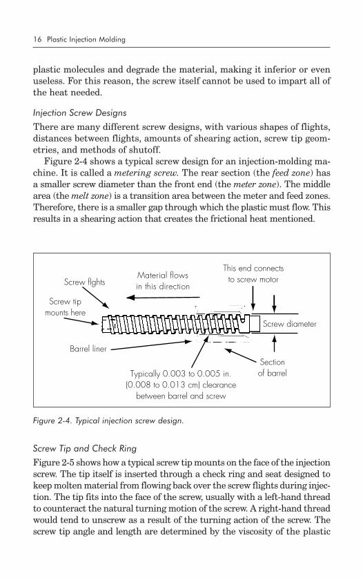
Figure 2-4 shows a typical screw design for an injection-molding ma-chine. It is called a metering screw. The rear section (the feed zone) hasa smaller screw diameter than the front end (the meter zone). The middlearea (the melt zone) is a transition area between the meter and feed zones.Therefore, there is a smaller gap through which the plastic must flow. Thisresults in a shearing action that creates the frictional heat mentioned.
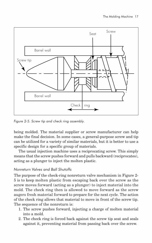
Screw Tip and Check Ring
Figure 2-5 shows how a typical screw tip mounts on the face of the injectionscrew. The tip itself is inserted through a check ring and seat designed tokeep molten material from flowing back over the screw flights during injec-tion. The tip fits into the face of the screw, usually with a left-hand threadto counteract the natural turning motion of the screw. A right-hand threadwould tend to unscrew as a result of the turning action of the screw. Thescrew tip angle and length are determined by the viscosity of the plastic
Figure 2-4. Typical injection screw design.
The Molding Machine 17
Check ring
Screw tip
ScrewSeat
Barrel wall
Barrel wall
being molded. The material supplier or screw manufacturer can helpmake the final decision. In some cases, a general-purpose screw and tipcan be utilized for a variety of similar materials, but it is better to use aspecific design for a specific group of materials.
The usual injection machine uses a reciprocating screw. This simplymeans that the screw pushes forward and pulls backward (reciprocates),acting as a plunger to inject the molten plastic.
Nonreturn Valves and Ball Shutoffs
The purpose of the check-ring nonreturn valve mechanism in Figure 2-5 is to keep molten plastic from escaping back over the screw as thescrew moves forward (acting as a plunger) to inject material into themold. The check ring then is allowed to move forward as the screwaugers fresh material forward to prepare for the next cycle. The actionof the check ring allows that material to move in front of the screw tip.The sequence of the nonreturn is:
1. The screw pushes forward, injecting a charge of molten materialinto a mold.
2. The check ring is forced back against the screw tip seat and sealsagainst it, preventing material from passing back over the screw.
Figure 2-5. Screw tip and check ring assembly.
18 Plastic Injection Molding
Stop pin Screw
Flow hole for plasticShutoff ball
Barrel wall
Barrel wall
3. The screw stops pushing and begins to turn (bringing new mate-rial forward).
4. The check ring slips forward under the influence of the pressurebuildup.
5. Molten plastic flows into the space in front of the screw tip.There are many different nonreturn mechanisms. The check-ring
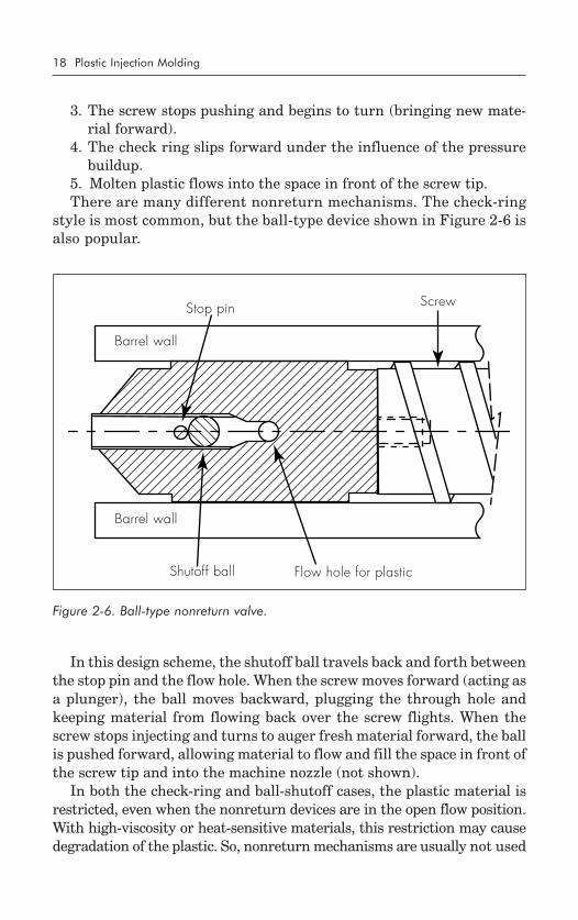
style is most common, but the ball-type device shown in Figure 2-6 isalso popular.
In this design scheme, the shutoff ball travels back and forth betweenthe stop pin and the flow hole. When the screw moves forward (acting asa plunger), the ball moves backward, plugging the through hole andkeeping material from flowing back over the screw flights. When thescrew stops injecting and turns to auger fresh material forward, the ballis pushed forward, allowing material to flow and fill the space in front ofthe screw tip and into the machine nozzle (not shown).
In both the check-ring and ball-shutoff cases, the plastic material isrestricted, even when the nonreturn devices are in the open flow position.With high-viscosity or heat-sensitive materials, this restriction may causedegradation of the plastic. So, nonreturn mechanisms are usually not used
Figure 2-6. Ball-type nonreturn valve.
The Molding Machine 19
when molding these materials; in fact, they are not usually required dueto the high viscosity of heat-sensitive plastics.
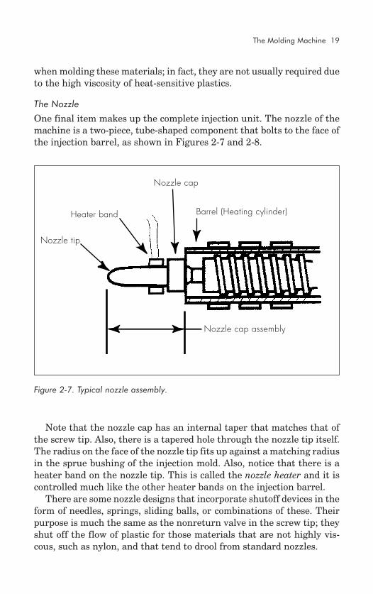
The Nozzle
One final item makes up the complete injection unit. The nozzle of themachine is a two-piece, tube-shaped component that bolts to the face ofthe injection barrel, as shown in Figures 2-7 and 2-8.
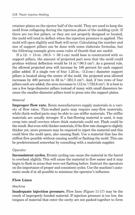
Note that the nozzle cap has an internal taper that matches that ofthe screw tip. Also, there is a tapered hole through the nozzle tip itself.The radius on the face of the nozzle tip fits up against a matching radiusin the sprue bushing of the injection mold. Also, notice that there is aheater band on the nozzle tip. This is called the nozzle heater and it iscontrolled much like the other heater bands on the injection barrel.
There are some nozzle designs that incorporate shutoff devices in theform of needles, springs, sliding balls, or combinations of these. Theirpurpose is much the same as the nonreturn valve in the screw tip; theyshut off the flow of plastic for those materials that are not highly vis-cous, such as nylon, and that tend to drool from standard nozzles.
Nozzle cap
Heater band
Nozzle tip
Barrel (Heating cylinder)
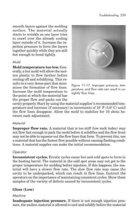
Nozzle cap assembly
Figure 2-7. Typical nozzle assembly.
20 Plastic Injection Molding
Determining Injection Requirements
Calculation
A variety of injection requirements for a specific application can be de-termined mathematically. Some of these are addressed below.
Shear rate. Shear rate is defined as the surface velocity of the plas-tic at the wall of the heating barrel, divided by the depth of the screwflight channel, and the units are feet (meters) per minute. The formula is:
SR = (D � N)/h,
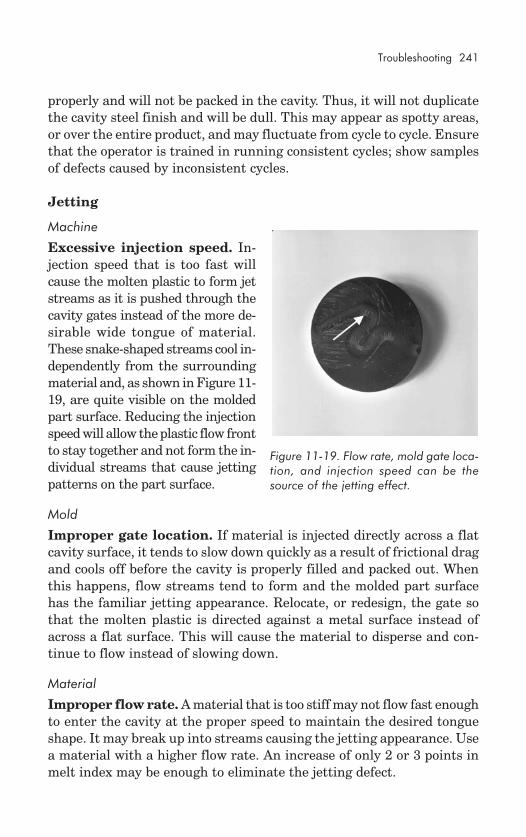
where SR = shear rateD = screw diameterN = rate of screw rotationh = depth of channel
An average shear rate value would be approximately 150 ft/min (45m/min), but each plastic has a specific shear rate beyond which it willdegrade. Heat-sensitive plastics such as polyvinyl chloride (PVC) have alower shear rate (approximately 100 ft/min [30 m/min]) while nonsensi-tive materials may have a shear rate of 175 ft/min (53 m/min) or higher.
Shear rate values have a direct effect on the allowable speed of screwrotation. For example, from the above formula, it can be determinedthat using a standard 2-in. (5.1-cm) diameter screw with a material havingan average shear rate of 150 ft/min would result in a maximum rotational
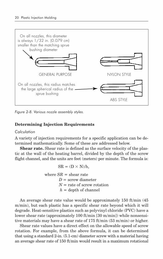
Figure 2-8. Various nozzle assembly styles.
GENERAL PURPOSE NYLON STYLE
ABS STYLE
On all nozzles, this diameteris always 1/32 in. (0.079 cm)smaller than the matching sprue
bushing diameter
On all nozzles, this radius matches the large spherical radius of the
sprue bushing
The Molding Machine 21
speed of 230 rpm. Any rotational speed above that value will result inovershearing the plastic and thereby degrading it.
Screw output. The amount of material an injection machine canprocess is rated in pounds per hour (kilograms per hour). It is deter-mined by how much horsepower is available to turn the screw. A 2-in.(5.1-cm)-diameter screw will normally withstand a maximum of 15 hp(11 kW). More than that may result in screw breakage. A 4.5-in. (11.4-cm)-diameter screw, on the other hand, will not break with up to 150 hp(110 kW) available to it.* For output, molding materials range from 5 to15 lb/h for each horsepower (2.3 to 6.8 kg/h for each kW) applied. There-fore, a 15-hp system (2-in.-diameter screw) is capable of producing from75 to 225 lb/h (34 to 102 kg/h) of plastic, depending on the viscosity(which affects shear rate).
Injection pressure. The average screw injection machine is capableof producing 20,000 psi (137,890 kPa) injection pressure in the heatingbarrel. This full pressure is available at the nozzle of the machine justbefore the material enters the mold. In most cases, it is advisable to usethe highest injection pressure and the fastest injection speed possible tominimize the overall cycle time of the molding process. While 20,000 psimay be available, it is prudent to use only the highest amount of pres-sure required for a specific material and specific application. Normalpractice is to begin molding at 6000 to 8000 psi (41,360 to 55,150 kPa)and increase/decrease pressure as necessary while optimizing the cycle.This is discussed in more detail later in this chapter and in Chapter 4.
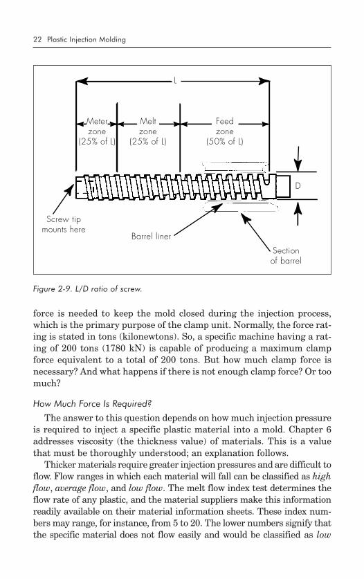
L/D ratio. A critical factor involved in creating available injectionpressure is the ratio of the length of the injection screw to its diameter(L/D). In Figure 2-9, note that the L dimension runs the entire length ofthe screw flights, and the D dimension goes over the largest diameter ofthe screw, which is also the overall flight diameter. The L dimension isnormally 20 times greater than the D dimension. So, if the screw has a 2.5-in. (6.4-cm) diameter, the length of the flighted section should be at least 50in. (127 cm). A 24:1 ratio is even better. In that case, a 2.5-in.-diameterscrew would have a length of 60 in. (152.4 cm). The greater the ratio, themore gentle the shearing action of the screw on the plastic material.
The Clamp Unit
Sizing the Clamp Unit
The clamp unit of an injection-molding machine is rated by the maxi-mum amount of clamp force the machine is capable of producing. This
*SPI Plastic Engineering Handbook, fourth edition (New York: Van NostrandReinhold, 1976).
22 Plastic Injection Molding
L
D
Meterzone
(25% of L)
Meltzone
(25% of L)
Feedzone
(50% of L)
Screw tipmounts here
Barrel liner
Sectionof barrel
force is needed to keep the mold closed during the injection process,which is the primary purpose of the clamp unit. Normally, the force rat-ing is stated in tons (kilonewtons). So, a specific machine having a rat-ing of 200 tons (1780 kN) is capable of producing a maximum clampforce equivalent to a total of 200 tons. But how much clamp force isnecessary? And what happens if there is not enough clamp force? Or toomuch?
How Much Force Is Required?
The answer to this question depends on how much injection pressureis required to inject a specific plastic material into a mold. Chapter 6addresses viscosity (the thickness value) of materials. This is a valuethat must be thoroughly understood; an explanation follows.
Thicker materials require greater injection pressures and are difficult toflow. Flow ranges in which each material will fall can be classified as highflow, average flow, and low flow. The melt flow index test determines theflow rate of any plastic, and the material suppliers make this informationreadily available on their material information sheets. These index num-bers may range, for instance, from 5 to 20. The lower numbers signify thatthe specific material does not flow easily and would be classified as low
Figure 2-9. L/D ratio of screw.
The Molding Machine 23
flow. The higher numbers signify a material that flows very easily andwould be classified as high flow.
It is not as important to remember a specific flow number as it is toknow in what range a material falls: high flow, average flow, or low flow.Then, since more injection pressure is needed to inject a low-flow mate-rial than a high-flow material, it is understood that a low-flow materialwill require much more clamp force to keep the mold closed against thathigher injection pressure.
A comparison of two materials will serve to demonstrate. A productmolded of polycarbonate (a low-flow plastic) may require an injectionpressure of 15,000 psi (103,410 kPa), while that same product molded ofacetal (a high-flow plastic) may require only 5000 psi (34,470 kPa). There-fore, the polycarbonate product will require a clamp force on the moldthat is approximately three times that for the acetal product.
Determining Projected Area
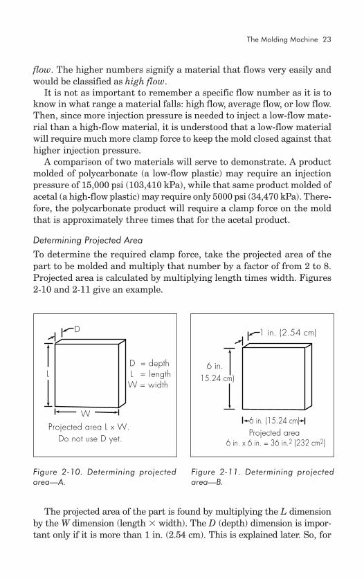
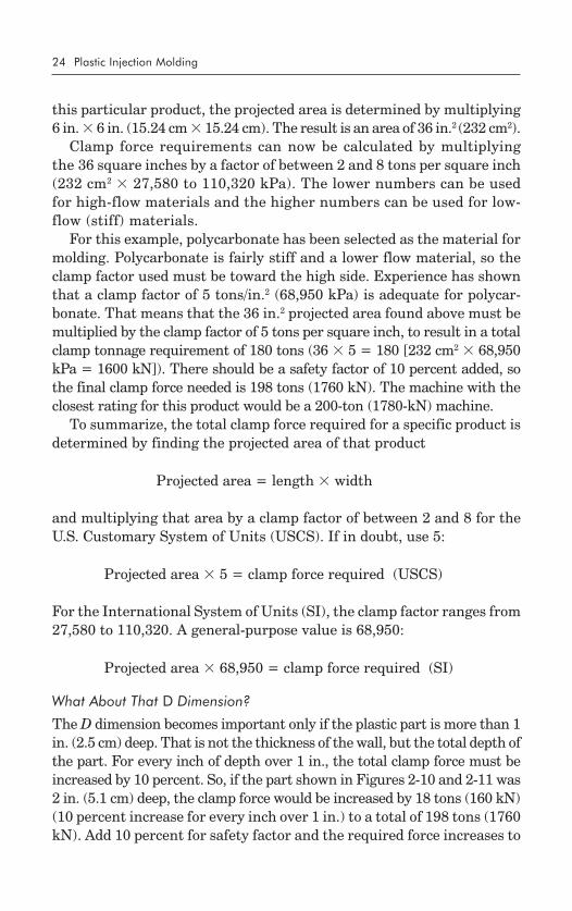
To determine the required clamp force, take the projected area of thepart to be molded and multiply that number by a factor of from 2 to 8.Projected area is calculated by multiplying length times width. Figures2-10 and 2-11 give an example.
The projected area of the part is found by multiplying the L dimensionby the W dimension (length � width). The D (depth) dimension is impor-tant only if it is more than 1 in. (2.54 cm). This is explained later. So, for
D
L
W
D = depth L = lengthW = width
Projected area L x W.Do not use D yet.
Figure 2-10. Determining projectedarea—A.
Figure 2-11. Determining projectedarea—B.
1 in. (2.54 cm)
6 in. 15.24 cm)
Projected area6 in. x 6 in. = 36 in.2 (232 cm2)
6 in. (15.24 cm)
24 Plastic Injection Molding
this particular product, the projected area is determined by multiplying6 in. � 6 in. (15.24 cm � 15.24 cm). The result is an area of 36 in.2 (232 cm2).
Clamp force requirements can now be calculated by multiplyingthe 36 square inches by a factor of between 2 and 8 tons per square inch(232 cm2 � 27,580 to 110,320 kPa). The lower numbers can be usedfor high-flow materials and the higher numbers can be used for low-flow (stiff) materials.
For this example, polycarbonate has been selected as the material formolding. Polycarbonate is fairly stiff and a lower flow material, so theclamp factor used must be toward the high side. Experience has shownthat a clamp factor of 5 tons/in.2 (68,950 kPa) is adequate for polycar-bonate. That means that the 36 in.2 projected area found above must bemultiplied by the clamp factor of 5 tons per square inch, to result in a totalclamp tonnage requirement of 180 tons (36 � 5 = 180 [232 cm2 � 68,950kPa = 1600 kN]). There should be a safety factor of 10 percent added, sothe final clamp force needed is 198 tons (1760 kN). The machine with theclosest rating for this product would be a 200-ton (1780-kN) machine.
To summarize, the total clamp force required for a specific product isdetermined by finding the projected area of that product
Projected area = length � width
and multiplying that area by a clamp factor of between 2 and 8 for theU.S. Customary System of Units (USCS). If in doubt, use 5:
Projected area � 5 = clamp force required (USCS)
For the International System of Units (SI), the clamp factor ranges from27,580 to 110,320. A general-purpose value is 68,950:
Projected area � 68,950 = clamp force required (SI)
What About That D Dimension?
The D dimension becomes important only if the plastic part is more than 1in. (2.5 cm) deep. That is not the thickness of the wall, but the total depth ofthe part. For every inch of depth over 1 in., the total clamp force must beincreased by 10 percent. So, if the part shown in Figures 2-10 and 2-11 was2 in. (5.1 cm) deep, the clamp force would be increased by 18 tons (160 kN)(10 percent increase for every inch over 1 in.) to a total of 198 tons (1760kN). Add 10 percent for safety factor and the required force increases to
The Molding Machine 25
217.8 tons (1936 kN). The nearest machine size to that requirementwould probably be a 225-ton (2002.5-kN) machine.
What Happens If Too Little Clamp Force Is Used?
If less than the calculated clamp force is used, the mold will not be ableto stay closed when the plastic material is injected into it. The resultwill be flash, or nonfilled parts, or both.
Flash is material that squeezes out of a closed mold because injectionpressure forces it out through any opening that allows material to flow.Sometimes flash is planned, but normally flash is unwanted because itcreates an uncontrolled injection pressure situation and because it mustbe removed prior to shipping the finished product. Normally, flash re-moval requires a secondary operation, which adds cost to the product.
Nonfilled parts result when the mold opens up slightly (because ofinsufficient clamp pressure), keeping the prescribed amount of plasticfrom flowing into the entire shape of the mold.
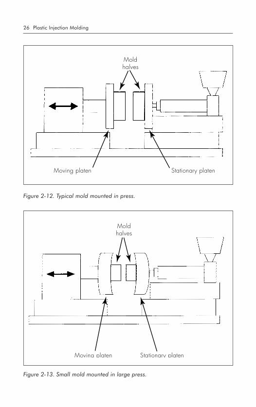
What Happens If Too Much Clamp Force Is Used?
If too much clamp force is used, the injection mold, or the press, can beseverely damaged. This damage can result from the collapse (or crush-ing) of the material used to make the mold (usually steel or aluminum).Molds can cost anywhere from a few thousand dollars to millions of dol-lars, and any damage is expensive to repair, if it can be repaired at all.
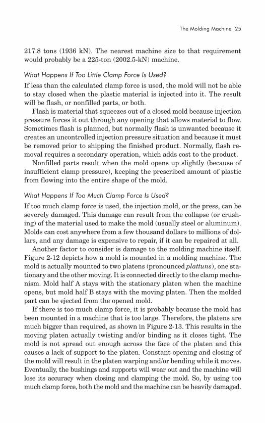
Another factor to consider is damage to the molding machine itself.Figure 2-12 depicts how a mold is mounted in a molding machine. Themold is actually mounted to two platens (pronounced plattuns), one sta-tionary and the other moving. It is connected directly to the clamp mecha-nism. Mold half A stays with the stationary platen when the machineopens, but mold half B stays with the moving platen. Then the moldedpart can be ejected from the opened mold.
If there is too much clamp force, it is probably because the mold hasbeen mounted in a machine that is too large. Therefore, the platens aremuch bigger than required, as shown in Figure 2-13. This results in themoving platen actually twisting and/or binding as it closes tight. Themold is not spread out enough across the face of the platen and thiscauses a lack of support to the platen. Constant opening and closing ofthe mold will result in the platen warping and/or bending while it moves.Eventually, the bushings and supports will wear out and the machine willlose its accuracy when closing and clamping the mold. So, by using toomuch clamp force, both the mold and the machine can be heavily damaged.
26 Plastic Injection Molding
Moldhalves
Moving platen Stationary platen
Figure 2-13. Small mold mounted in large press.
Moldhalves
Moving platen Stationary platen
Figure 2-12. Typical mold mounted in press.
The Molding Machine 27
SUMMARY
The basic components of the injection-molding machine can be dividedinto two sections: the injection unit, rated in ounces (grams) of plasticavailable to inject, and the clamp unit, rated in total tons (kilonewtons)of clamping force available to keep the mold closed.
The injection unit consists of a hopper that feeds fresh material tothe machine, a barrel that is heated by external heater bands, an augeringscrew that is mounted lengthwise in the heated barrel, and a nozzle thatconnects the injection unit to the mold.
The clamp unit consists of a clamping mechanism that is either me-chanical or hydraulic, or both, and in some cases all-electric versions ofmechanical. The clamp unit is used to keep the mold closed during theinjection phase of the molding cycle. The amount of clamp force requiredis determined by the projected area of the product being molded.
QUESTIONS
1.What material is used as a standard for determining the capacityof an injection cylinder?
2.What percentage of this capacity should be injected during anysingle cycle?
3.How do you calculate the weight of one material versus another,knowing the specific gravity of both?
4.Name the three heater zones found in the injection barrel. Whereis the fourth zone?
5.On the average, how often will a standard hopper require refill-ing?
(a) 1 hour (b) 2 hours(c) 4 hours (d) 8 hours
6.How much pressure can the average molding machine generate inthe injection cylinder?
7.What is the primary purpose of the clamp unit? 8.What is the formula for determining how much clamp force is re-
quired? 9.How is projected area determined?10.What happens if:
(a) excessive clamp force is used?(b) not enough clamp force is used?
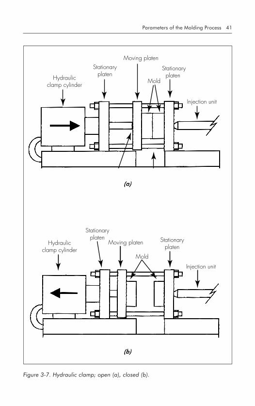
Parameters of theMolding Process
IDENTIFYING THE PARAMETERS
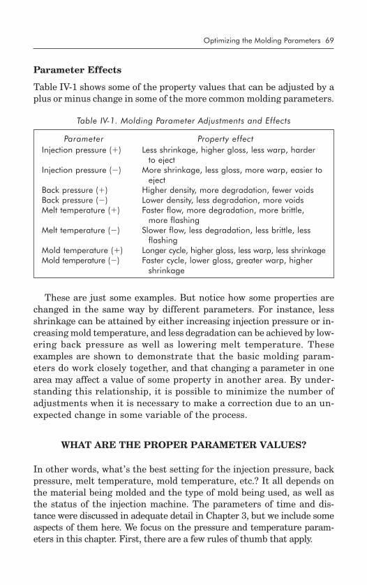
Numerous variables affect the injection-molding process. In fact, a re-cent study itemized more than 200 different parameters that had a di-rect or indirect effect on the process.
Many years ago, I was asked by my manager to compile a list of all thevarious parameters associated with controlling the injection-molding pro-cess. At the time, I thought this would be an easy task and eagerly pur-sued the answers. I envisioned a short list comprising such things asinjection pressure, cycle time, barrel temperature, and a few other com-mon items.
I soon realized that I had grossly underestimated the number of pa-rameters. For every parameter I found, another would appear. For in-stance, injection pressure consisted of more than one item. There wereinitial injection pressure, second- and up to fifth-stage injection pres-sure, holding pressure, back pressure, and line pressure, all of whichhad a direct effect on each other. Even items such as humidity and am-bient temperature had an effect on the molding process. Shift changes,relief operators, fans blowing, housekeeping, age of equipment, size ofmachine, location of press, pressure of cooling water, all seemed to havedirect or indirect effects on the injection-molding process.
I found, for example, that between the hours of 6 a.m. and 8 a.m.,scrap rates increased dramatically and all the molding machines seemedto go out of control. Further investigation showed that, because we werelocated in a very small town, water pressure would drop at that time ofthe morning because of so many people getting ready for work. Whenthe water pressure dropped, the cooling devices on our equipment didnot function effectively and the machines would heat up. This had aneffect on the overall cycle times, temperature of the operating oil, andtemperatures of the individual molds. By the time adjustments weremade to compensate for the unknown cause of the problem, the waterpressure would return to normal and the changes that had been madehad to be undone in order to return to normal operation.
3
30 Plastic Injection Molding
Although there are so many dif-ferent variables, it is not impossibleto get control of the injection-mold-ing process. What is needed is amore practical approach to under-standing all of these parameters,and targeting those that have thegreatest effect on the overall qual-ity and cost-effectiveness of the fin-ished molded product.
Figure 3-1 shows that all of theparameters involved can be placedinto four basic categories: tempera-ture, pressure, time, and distance.The relative importance of the cat-egories is shown by the size of the
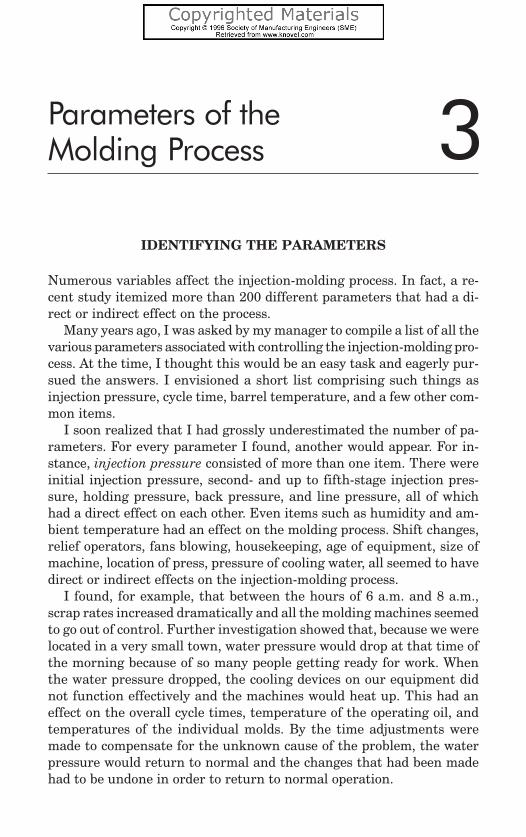
circles. Thus, temperature is the most important, followed by pressure,time, and distance. However, each is dependent on the other, and chang-ing one will affect one or all of the others. The discussion that followsaddresses that interdependence.
TEMPERATURE
A variety of temperatures affect the injection-molding process, rang-ing from melt temperature to mold temperature, and including evenambient temperature.
Melt Temperature Control
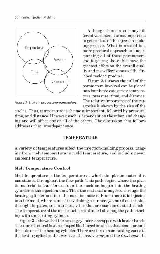
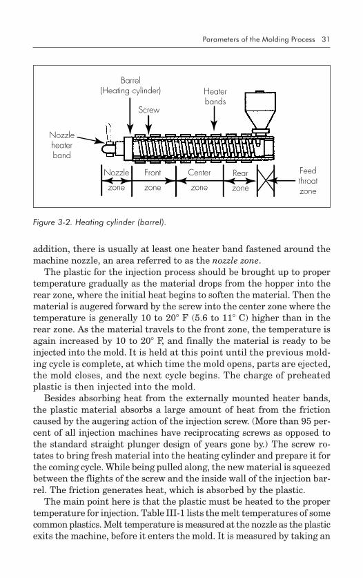
Melt temperature is the temperature at which the plastic material ismaintained throughout the flow path. This path begins where the plas-tic material is transferred from the machine hopper into the heatingcylinder of the injection unit. Then the material is augered through theheating cylinder and into the machine nozzle. From there it is injectedinto the mold, where it must travel along a runner system (if one exists),through the gates, and into the cavities that are machined into the mold.The temperature of the melt must be controlled all along the path, start-ing with the heating cylinder.
Figure 3-2 shows that the heating cylinder is wrapped with heater bands.These are electrical heaters shaped like hinged bracelets that mount aroundthe outside of the heating cylinder. There are three main heating zones tothe heating cylinder: the rear zone, the center zone, and the front zone. In
Figure 3-1. Main processing parameters.
Temperature
Pressure
Time
Distance
Temperature
Parameters of the Molding Process 31
Barrel(Heating cylinder)
Nozzleheaterband
Heaterbands
Screw
Nozzle
zone
Front
zone
Center
zone
Rear
zone
Feedthroatzone
addition, there is usually at least one heater band fastened around themachine nozzle, an area referred to as the nozzle zone.
The plastic for the injection process should be brought up to propertemperature gradually as the material drops from the hopper into therear zone, where the initial heat begins to soften the material. Then thematerial is augered forward by the screw into the center zone where thetemperature is generally 10 to 20� F (5.6 to 11� C) higher than in therear zone. As the material travels to the front zone, the temperature isagain increased by 10 to 20� F, and finally the material is ready to beinjected into the mold. It is held at this point until the previous mold-ing cycle is complete, at which time the mold opens, parts are ejected,the mold closes, and the next cycle begins. The charge of preheatedplastic is then injected into the mold.
Besides absorbing heat from the externally mounted heater bands,the plastic material absorbs a large amount of heat from the frictioncaused by the augering action of the injection screw. (More than 95 per-cent of all injection machines have reciprocating screws as opposed tothe standard straight plunger design of years gone by.) The screw ro-tates to bring fresh material into the heating cylinder and prepare it forthe coming cycle. While being pulled along, the new material is squeezedbetween the flights of the screw and the inside wall of the injection bar-rel. The friction generates heat, which is absorbed by the plastic.
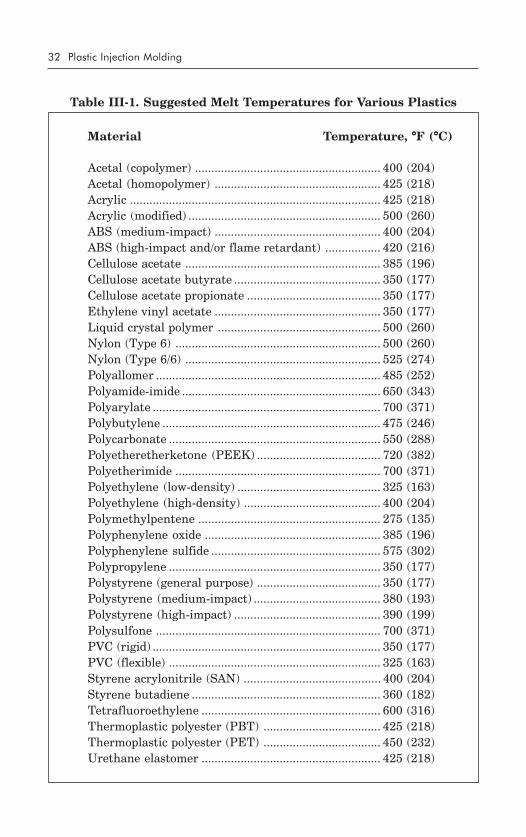
The main point here is that the plastic must be heated to the propertemperature for injection. Table III-1 lists the melt temperatures of somecommon plastics. Melt temperature is measured at the nozzle as the plasticexits the machine, before it enters the mold. It is measured by taking an
Figure 3-2. Heating cylinder (barrel).
32 Plastic Injection Molding
Table III-1. Suggested Melt Temperatures for Various Plastics
“air shot” and plunging a probe from a measuring instrument with afast response time (1 second is acceptable) into the plastic melt. An airshot is made with the injection sled pulled back so the injection unitdoes not touch the mold. The material is then released as in a normalcycle, but it is injected into air rather than the mold. It is allowed tofall onto a tray made for the purpose and its temperature is then quicklymeasured. The temperature at that point should be within 10� F (5.6�
C) of the desired temperature.
Insulation Blankets
To better regulate and control the temperature of the injection barrel(cylinder), an insulation blanket is used. This is a nonflammable jacketthat fits around the outside of the heating cylinder, directly over all theheater bands, and keeps heat from being lost to the atmosphere. It makeslittle sense to have the heater bands supply a great amount of heat towarm up plastic inside the barrel while much of that heat is lost to thesurrounding air. With insulation blankets, heat generated by the heaterbands is directed only toward the barrel; less energy is required to heatthe plastic, and operating costs are lower. Use of blankets can reduceenergy costs to heat the plastic by 25 percent or more.
Mold Temperature Control
The plastic material is now ready to flow into the mold. First, it musttravel through the machine nozzle, which is the last heating zone pro-vided by the machine. After the material exits the nozzle and enters themold, it immediately begins to cool down as the mold absorbs heat fromit. The rate at which this heat is absorbed determines how far the plas-tic will flow before it begins to solidify and stop moving. Each product,depending on its design and plastic material, demands specific cooling rates,and this rate of cooling is critical to product quality. Therefore, the moldtemperature must be regulated in order to regulate the cooling rate of theplastic. This is done by connecting the mold to a temperature control unitthat normally utilizes water as a medium. The water is circulated throughthe mold and held at a preset temperature by heating or cooling in cycles.
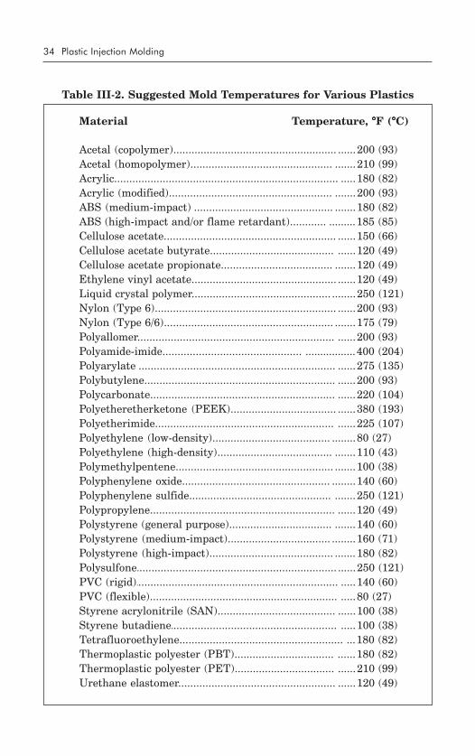
Every combination of plastic and product has a specific temperatureat which the mold should be maintained to ensure quality molding, butTable III-2 suggests starting points for a variety of common plastics.
The mold temperature is measured directly from the molding surfaceof the tool with a solid probe on a pyrometer device. Usually, readingsfrom several areas are averaged. Remember that these temperaturesare recommended starting points only and should be adjusted for spe-cific applications.
34 Plastic Injection Molding
Table III-2. Suggested Mold Temperatures for Various Plastics
The object of the cooling process is to lower the temperature of themolded plastic to the point at which it solidifies again. When the plasticreaches that point, it can be ejected from the mold with relative struc-tural safety. That simply means that the plastic part will not move ex-cessively, causing warpage, twisting, or other shrinkage-related problemsas the plastic continues to cool.
Postmold Shrinkage Control
Although molded thermoplastic products appear to be stable, they willcontinue to cool and shrink for up to 30 days after being ejected fromthe mold. Most (95 percent) of the total shrinkage will occur during thetime the plastic is cooling in the mold. The remaining 5 percent will takeplace over the next 30 days, but most of that will happen within the firstfew hours after ejection from the mold. Thus, it is important to inspectmolded parts after they have been allowed to stabilize. Initial inspectioncan be performed as soon as the part cools to the touch after being ejected.But more accurate inspection can only be performed after the part hascooled for 2 to 3 hours or more.
Hydraulic System Temperature Control
Besides melt temperature and mold temperature, there is the tempera-ture of the hydraulic system of the press to be considered. The tempera-ture of the hydraulic oil in these systems must be maintained between80 and 140� F (27 and 60� C), in most cases. If the oil is too cool, it will bethick (viscous) and cause sluggish action of hydraulic components. If itis too hot, it will break down, causing components to stick or valves tomalfunction. The temperature of the oil is regulated by a heat exchangermounted on the injection machine. This heat exchanger acts like a ra-diator on a car and cools the oil by circulating it around tubes filled withcirculating water. These tubes must be kept clean and require periodicflushing with an acid cleaner. If the oil is allowed to overheat, that heatwill eventually transfer throughout the entire machine, including theplatens to which the mold is mounted. This will cause the mold to over-heat and result in poor-quality parts.
Ambient Temperature Control
Ambient temperature is also a concern. A particular job may be runningperfectly well until someone opens a loading dock door or turns on a coolingfan in the vicinity of the molding press. This causes a change in the tem-perature of the air surrounding the machine and this, in turn, results in
36 Plastic Injection Molding
Mold "A" half
Mold "B" half
Opening fitsover spruebushing
Insulation sheets
fluctuations in the readings provided by the various temperature con-trol units of the machine. The injection process then becomes unstablefor a period of approximately 2 hours, assuming no other changes occurto alter the ambient conditions. If more changes do occur, the process isunstable for longer periods of time.
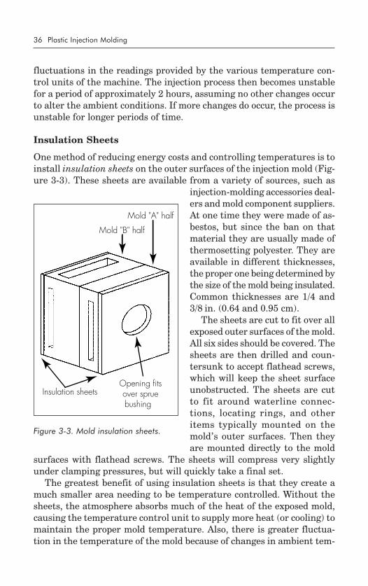
Insulation Sheets
One method of reducing energy costs and controlling temperatures is toinstall insulation sheets on the outer surfaces of the injection mold (Fig-ure 3-3). These sheets are available from a variety of sources, such as
injection-molding accessories deal-ers and mold component suppliers.At one time they were made of as-bestos, but since the ban on thatmaterial they are usually made ofthermosetting polyester. They areavailable in different thicknesses,the proper one being determined bythe size of the mold being insulated.Common thicknesses are 1/4 and3/8 in. (0.64 and 0.95 cm).
The sheets are cut to fit over allexposed outer surfaces of the mold.All six sides should be covered. Thesheets are then drilled and coun-tersunk to accept flathead screws,which will keep the sheet surfaceunobstructed. The sheets are cutto fit around waterline connec-tions, locating rings, and otheritems typically mounted on themold’s outer surfaces. Then theyare mounted directly to the mold
surfaces with flathead screws. The sheets will compress very slightlyunder clamping pressures, but will quickly take a final set.
The greatest benefit of using insulation sheets is that they create amuch smaller area needing to be temperature controlled. Without thesheets, the atmosphere absorbs much of the heat of the exposed mold,causing the temperature control unit to supply more heat (or cooling) tomaintain the proper mold temperature. Also, there is greater fluctua-tion in the temperature of the mold because of changes in ambient tem-
Figure 3-3. Mold insulation sheets.
Parameters of the Molding Process 37
perature and airflow around the mold. This requires greater and morefrequent exercise of mold temperature control, which incurs higher en-ergy use and higher costs. The insulation sheets create an environmentthat includes only the mold itself; therefore, that is all that needs to becontrolled by the temperature control units. A higher degree of controlcan be attained, which results in lower temperature excursions, result-ing in greater efficiency and lower energy costs. In fact, in comparingenergy costs between two identical molds, one with insulation sheetsand one without, the mold with insulation sheets showed a 25 percentsavings in energy costs. Insulation sheets also minimize (or eliminate)sweating of the mold caused by high-humidity conditions.
PRESSURE
There are two areas in the injection machine that require pressure andpressure control: the injection unit and the clamp unit. They are closelyrelated in that they are opposing pressures—the clamp unit must de-velop enough clamp pressure to overcome the pressure developed by theinjection unit during the molding process.
Injection Unit
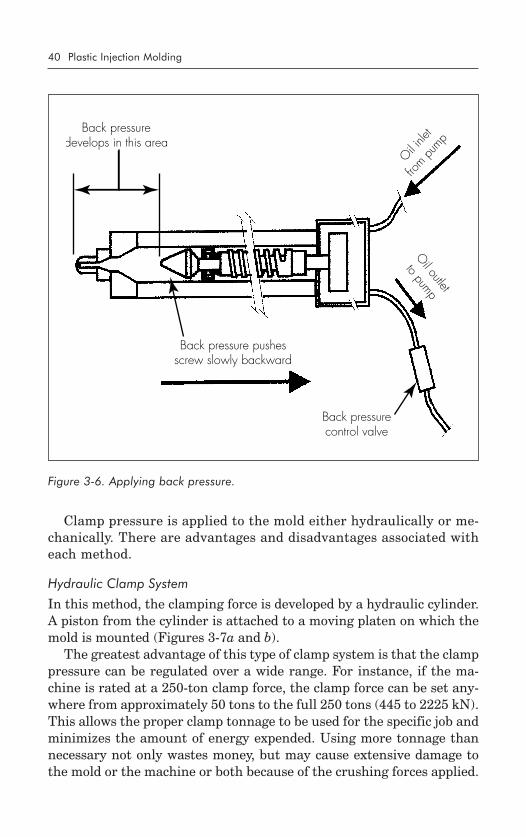
Three basic types of pressure are developed by the injection unit: initialpressure, hold pressure, and back pressure.
Initial Injection Pressure
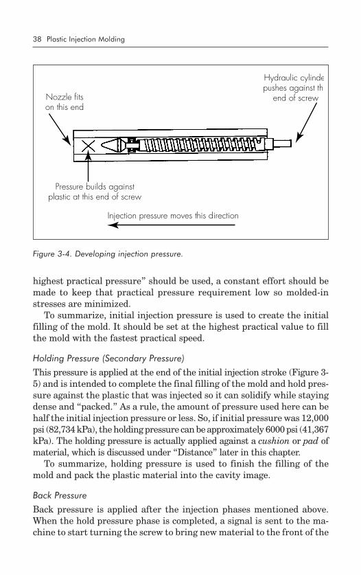
This is the first pressure that is applied to the molten plastic. It devel-ops as the result of main system hydraulic pressure pushing against theback end of the injection screw (or plunger) (Figure 3-4).
The amount of pressure developed by the main system is on the orderof 2000 psi (13,789 kPa). Some systems are capable of producing morethan that, but 2000 psi is the most common line pressure. This pressureis converted to a maximum of 20,000 psi (137,890 kPa) at the nozzle ofthe injection unit (where the plastic first enters the mold) by the designand shape of the injection screw. In most cases, the full 20,000 psi is notrequired for filling a mold, and most products can be molded in a rangeof from 5000 to 15,000 psi (34,472 to 103,418 kPa). The pressure actu-ally required depends on the plastic being molded, the viscosity and flowrate of the plastic, and the temperatures of the plastic and the mold.
The ideal situation is to be able to fill the mold initially with the highestpractical pressure in the shortest practical time. Normally, the initial fillcan be accomplished in less than 3 seconds. Note that even though “the
38 Plastic Injection Molding
Nozzle fitson this end
Hydraulic cylindepushes against thi
end of screw
Pressure builds againstplastic at this end of screw
Injection pressure moves this direction
highest practical pressure” should be used, a constant effort should bemade to keep that practical pressure requirement low so molded-instresses are minimized.
To summarize, initial injection pressure is used to create the initialfilling of the mold. It should be set at the highest practical value to fillthe mold with the fastest practical speed.
Holding Pressure (Secondary Pressure)
This pressure is applied at the end of the initial injection stroke (Figure 3-5) and is intended to complete the final filling of the mold and hold pres-sure against the plastic that was injected so it can solidify while stayingdense and “packed.” As a rule, the amount of pressure used here can behalf the initial injection pressure or less. So, if initial pressure was 12,000psi (82,734 kPa), the holding pressure can be approximately 6000 psi (41,367kPa). The holding pressure is actually applied against a cushion or pad ofmaterial, which is discussed under “Distance” later in this chapter.
To summarize, holding pressure is used to finish the filling of themold and pack the plastic material into the cavity image.
Back Pressure
Back pressure is applied after the injection phases mentioned above.When the hold pressure phase is completed, a signal is sent to the ma-chine to start turning the screw to bring new material to the front of the
Figure 3-4. Developing injection pressure.
Parameters of the Molding Process 39
barrel in preparation for the next cycle, or shot (so called because plasticshoots into the mold). The screw is not pulled back. Instead, the churn-ing, or augering, action of the screw brings new material forward, andas that material fills up in front of the screw, the material itself beginsto push the screw backward (Figure 3-6).
The back pressure is small compared to the injection pressure. A mini-mum of 50 psi (345 kPa) and a maximum of 500 psi (3447 kPa) is all thatis required. The proper method of determining the amount of back pres-sure is to begin at 50 psi and increase, only if necessary, in increments of10 psi (69 kPa) until the proper mix and density are achieved. Use ofback pressure helps ensure consistency in part weight, density, and ma-terial appearance. It also helps to squeeze out any trapped air or mois-ture not eliminated by predrying the material. This minimizes (or eveneliminates) voids in the molded product. If less than 50 psi back pres-sure is attempted, the controls and gages are not consistent nor accu-rate enough to maintain or indicate the actual pressure being developed.Thus, faulty readings and settings can occur. If more than 500 psi backpressure is attempted, the screw may not return at all, or it will stayforward much too long, and the plastic material will degrade under theextreme shear imparted to it from the continued churning action of thescrew. In the case of reinforced plastics (such as glass-filled), the rein-forcement material will break down, and this results in much lessstrength than is required in the molded product.
Clamp Unit
The purpose of developing clamp pressure is to keep the mold clampedshut against the forces developed when injection pressure pushes plas-tic into the closed mold. Therefore, the amount of clamp force must beat least equal to the amount of injection force.
At end of injection stroke the screwstays forward in a "holding" positionand maintains pressure on the plastic
Figure 3-5. Applying holding pressure.
40 Plastic Injection Molding
Back pressuredevelops in this area
Oil inle
t
from pu
mp
Back pressure pushesscrew slowly backward
Back pressurecontrol valve
Oil outlet
to pump
Clamp pressure is applied to the mold either hydraulically or me-chanically. There are advantages and disadvantages associated witheach method.
Hydraulic Clamp System
In this method, the clamping force is developed by a hydraulic cylinder.A piston from the cylinder is attached to a moving platen on which themold is mounted (Figures 3-7a and b).
The greatest advantage of this type of clamp system is that the clamppressure can be regulated over a wide range. For instance, if the ma-chine is rated at a 250-ton clamp force, the clamp force can be set any-where from approximately 50 tons to the full 250 tons (445 to 2225 kN).This allows the proper clamp tonnage to be used for the specific job andminimizes the amount of energy expended. Using more tonnage thannecessary not only wastes money, but may cause extensive damage tothe mold or the machine or both because of the crushing forces applied.
Figure 3-6. Applying back pressure.
Parameters of the Molding Process 41
Figure 3-7. Hydraulic clamp; open (a), closed (b).
(b)(b)(b)(b)(b)
Hydraulicclamp cylinder
Stationaryplaten
Moving platen
Mold
Stationaryplaten
Injection unit
(a)(a)(a)(a)(a)
Hydraulicclamp cylinder
Stationaryplaten
Moving platen
Mold
Stationaryplaten
Injection unit
42 Plastic Injection Molding
The greatest disadvantage of the hydraulic clamp is that when ton-nage requirements approach the maximum rating, extreme injectionpressures may overcome the clamp force and blow the mold open. Forinstance, if a mold requiring 225 tons is placed in a 250-ton machine andthe injection pressure is on the high side (15,000 psi [103,410 kPa] ormore), the potential exists for the injection pressure to overpower the clamppressure, in which case the mold will open while plastic is being injected.This results in flash, short shots, and possible cycle interruption.
Mechanical Clamp (Toggle) System
The mechanical system utilizes a knuckle and scissors (toggle) mechanismto close the mold. The toggle is attached to the moving platen on which themold is mounted. When the clamp is open (Figure 3-8a), a small hydrauliccylinder actuates the arms by pushing along their centerline. As the pistonmoves forward, it pulls the arms together, closing the mold (Figure 3-8b).
For the mold to close under full tonnage, the knuckles must actuallypass center to lock. If they do not lock, they will not hold in the forwardposition and the injection pressure will blow the mold open. This can bedemonstrated by watching a person push an arm straight out from thebody. When the elbow is past center and straight, the arm is locked inthe forward position and is difficult to push back until the elbow is relaxed.
The principal advantage of the mechanical system is that once it is lockedin place, it is virtually impossible to blow the mold open even if injectionpressures are beyond those required. Of course, there are limits to the pres-sure it can sustain, and eventually machine damage will occur if the injec-tion pressures are held beyond requirements for extended periods. But oncethe system locks, there is no doubt that full tonnage force is available.
There are two distinct disadvantages to this system. First, there isconsiderable wear on the knuckle linkages and bushings must be re-placed regularly. Second, there is little accommodation for adjustmenton this system. If the machine is rated at 250 tons, the only tonnageavailable is 250 tons. It cannot be reduced, except minimally. Thus asmaller, borderline mold could not be run in this press without the dis-tinct possibility of damage from crushing.
Some machines combine both hydraulic and mechanical systems formold clamping, and some even incorporate electric motors for perform-ing the mechanical action instead of hydraulic cylinders.
How Much Pressure is Needed?
As mentioned, total clamp force needed is determined by the projected areaof the part being molded. This projected area is multiplied by a clamp
Parameters of the Molding Process 43
Hydraulic cylinderconnects to moving
platen
Stationaryplaten
Movingplaten
Mold
Stationaryplaten
Injection unit
Hydraulic cylinder pushes movingplaten forward until toggle action locks
Tie bars connect thestationary platens
Figure 3-8. Mechanical clamp; open (a), closed (b).
force of from 2 to 8 tons for each square inch (27,580 to 110,320 kN/m2)of that projected area. As a rule of thumb, 4 or 5 tons/in.2 (55,160 to68,950 kN/m2) can be used for most products. If the plastic material is verystiff, it will require more injection pressure to fill the mold, thus more clamptonnage to hold the mold closed. Conversely, if the plastic material has goodflow characteristics, less injection pressure will be needed to fill the moldand a lower clamp tonnage will be adequate to keep the mold closed.
TIME
Gate-to-gate Cycle Time
During the injection-molding process, many internal activities are tak-ing place. Some occur simultaneously with others (parallel activities),and some must wait until others are completed (serial activities). Theoverall cycle time provides a measure of the time required for all theseactivities. This is usually referred to as the gate-to-gate cycle time be-cause it is common to start timing the overall cycle as soon as the ma-chine operator closes the safety gate of the machine. The timing continuesuntil the operator closes the same gate to start the next cycle. The en-tire amount of time elapsed between these two actions is the gate-to-gate or overall cycle time. (Timing of the overall cycle can actually bestarted at any point in the cycle as long as the timing continues untilthat same point in the next cycle.) The cycle time provides the only wayto get an accurate picture of how long it takes to mold a product. Thisnumber is then used to determine the actual cost involved to manufac-ture the product. This, in turn, is used to determine the selling price of theproduct. Determining molding costs will be discussed later in this chapter.
According to the true gate-to-gate concept, the total overall cycle startswith the operator closing the safety gate and includes the activities listedin Table III-3 with typical time estimates. While the numbers add to 42seconds, the actual total cycle is approximately 30 seconds because someoperations are being performed during the time that others are operat-ing, so there is an overlap. Each of these items is described and dis-cussed in Table III-3.
Gate Close Time
Gate close time is the time it takes for the machine operator to actuallyclose the safety gate, which starts the cycle. Each person operates a littledifferently, so the gate close time may fluctuate from operator to operator.Also, although a molding job may be set up and running fine, as soon as
Parameters of the Molding Process 45
a relief operator is placed on the job, the cycle begins to change. Thisdoes not mean the relief operator is not performing the job properly. Itsimply shows that each person operates at a slightly different pace, andthis must be taken into consideration when setting up and running ajob. Thus, the timing of the gate closing must be controlled as consis-tently as possible. The operators should be trained and informed thatany slight change in the pace at which they close the gate may greatlyaffect the overall machine cycle. In fact, an increase of 2 seconds in theaverage cycle time of 30 seconds can cost approximately $20,000 annu-ally, depending on the number of cavities, hourly wages, and cost of utili-ties. That additional cost must be paid for by the molder because thecustomer is not responsible for the increased cycle time. Of course, the op-posite is also true: if the cycle can be reduced by 2 seconds, the molder canrealize an additional profit of that same $20,000 annually. This shows theimportance of maintaining consistent cycles and developing realistic cycles.
Mold Close Time
Mold close time is the amount of time it takes for the moving half of themold to travel the entire distance to meet the stationary half of the mold,and lock up with full clamping force. This motion is usually initiated bythe closing of a limit switch when the operator closes the safety gate tostart the cycle.
There are actually two mold closing phases. The first is the initial clos-ing that quickly brings the two mold halves together under low pressure.This takes approximately 1 to 2 seconds. But this action stops when themold halves come to within half an inch (a centimeter) or less of fully
46 Plastic Injection Molding
closing. At that point, the speed slows down. This is a safety feature thatkeeps the mold from closing all the way before going into high pressure,should there be an obstruction within it, such as a broken-off plasticpart from the previous cycle. It also allows any slides, cams, or other“actions” to operate slowly without danger of crushing. This final clos-ing normally takes from 2 to 3 seconds.
Initial Injection Time
When the mold closes completely, either a limit switch or pressure buildup(or both) signals the injection screw to push forward and inject the mol-ten plastic into the closed mold. The screw does not turn at this point,but only acts as a plunger to force the material into the mold. This ini-tial injection is performed at the highest practical pressure for the spe-cific application (normally 10,000 to 15,000 psi [68,940 to 103,410 kPa])in the fastest practical amount of time. In most cases, the time is lessthan 2 seconds and rarely more than 3 seconds. Sometimes, dependingon machine design, this action is divided into two or three smaller ac-tions. Then, the total injection time normally does not exceed 4 to 5seconds. The initial injection time is controlled by a timer. If boosterinjection is available, it will be included in the first stage of the initialinjection time. When a booster phase is included, the injection machine’sentire hydraulic system (injection and clamp) is combined to push alarge volume of oil through the system. This can greatly increase thespeed at which the material is injected into the mold.
Injection Hold Time
On most machines, the timer for initial injection time (also called injec-tion forward time) controls the total amount of time that the injectionscrew is pushing forward. The initial injection time is the first part ofthat time, and injection hold is the latter part. On some machines, thehold time and initial time are on separate timers.
The hold time is the amount of time the injection screw maintainspressure against the plastic after it has been injected into the mold. Thispressure is applied against the cushion or pad long enough for the gateto freeze off (solidify). The molten plastic enters the mold cavity imagethrough a gate. The gate is the first point at which the plastic actually”sees” the cavity image. Once all the required material goes through thegate and packs the cavity image, the plastic is allowed to cool under holdpressure, down to the point at which it all solidifies. But, because it isnormally the thinnest part of the cavity image, the gate is the first thingto solidify. When it does, there is no reason to maintain pressure be-
Parameters of the Molding Process 47
cause the plastic that is in the cavity lies beyond the solidified gate andthe pressure from the injection unit no longer has any effect on it. So,pressure is held against the gate only long enough for the gate to freeze.In most cases, this is only a matter of a few seconds. A gate with a thicknessof 1/16 in. (0.16 cm) would take approximately 6 seconds to solidify.
Cooling Time
Cooling time is probably the most important time in the entire injectionprocess. It is the amount of time required for the plastic material to cooldown to the point at which it has solidified and an extra amount of timeto allow the plastic part to become rigid enough to withstand the ejec-tion process (in which the finished molded product is pushed out of themold after the entire cycle is completed). Even though the plastic maycool enough to solidify, it may not be rigid enough to be ejected. This isbecause the curing process actually takes as long as 30 days to finalize.The initial curing is rapid, and 95 percent of the total curing takes placein the mold. But the other 5 percent takes place outside the mold. If theouter skin of the plastic product is solidified to a sufficient depth, theremaining cooling will not have an appreciable effect on the molded part.But if the skin is too thin, the remaining cooling will cause shrinkagestress to build up and the molded part may warp, twist, blister, or crack.
The key to minimizing these problems is to keep the part in the moldfor a sufficiently long time, but no longer than necessary because time ismoney, and long cycles are expensive. Most material suppliers are morethan happy to share cooling time requirements for their materials atvarying thicknesses (the thicker the part, the longer the cooling timerequired), but, on the average, a 1/16-in. (0.16 cm) thick wall should takeapproximately 9 to 12 seconds to solidify (depending on material) to thepoint at which it can be ejected from the mold without undue distortion.
Screw Return Time
After the screw pushes the plastic into the mold and holds it there untilthe gate freezes, the screw is ready to start turning to auger fresh mate-rial into the heating cylinder in preparation for the next shot. Althoughthere is not usually a specific timer that can be used to adjust how longthe screw should turn, the turning must take place before the coolingtimer (sometimes called the dwell timer) times out. If the screw has notturned for a long enough time, there will not be enough material readyfor the next shot. If the cooling timer times out, the mold may not beallowed to open until the screw finishes its travel.
48 Plastic Injection Molding
The amount of time required for the screw to turn and return to theinject position is determined by how much back pressure is being ap-plied (the more back pressure, the longer it takes the screw to return)and how much material needs to be prepared for the next shot. If themachine is the correct size for the job and the back pressure is properlyset, the screw return time should be a few seconds less than the totalcooling timer setting. In most cases, this amounts to approximately 6 to8 seconds. The point at which the screw stops its return travel is deter-mined by a limit switch. This switch is set to a point that ensures thereis enough material ready for the next shot. As the screw turns (augers),it is pushed back toward its starting point by the pressure built up in frontof it by the incoming material that augers forward. The screw continues toturn until it has traveled back and touches the preset limit switch, at whichpoint the turning stops. Except for continuous purging, this is the onlytime that the screw actually turns (brings material forward). It does notturn during injection (unless something is wrong with the machine), exceptunder rare circumstances when the turning is used to force more materialinto the mold. This is usually attempted only because the mold was notplaced in a machine of correct size; it is a practice that should be avoided. Ifthe screw does turn during injection, it usually means that the check ringor shutoff mechanism is worn or broken and should be replaced.
Mold-open Time
Mold-open time is the amount of time it takes for the mold to open. It isnot determined by a timer (unless the machine is running fully auto-matically), but rather by the distance required for the mold to fully openand the speed at which it does it.
Commonly the mold opens in two stages. The first stage is very slowand the travel is short. This allows the vacuum created during the mold-ing process to dissipate partially. When the plastic is injected into themold, it displaces any air that is trapped in the closed mold. When air isdisplaced, a vacuum occurs. This vacuum causes the two mold halves towant to cling to each other. If the vacuum is not released, the two halvesstay together when the machine opens, resulting in broken clamps anddamaged molds and equipment. So, the vacuum is allowed to partiallyrelease by opening the mold slowly. After opening approximately 1/4 in.(0.6 cm) to relieve some of the vacuum, the mold is allowed to open fully.If there are fragile cams, slides, or lifting devices in the mold, it may benecessary to open slowly for a longer distance than 1/4 in. This will al-low those devices to operate without slamming or shuddering. Then themold is allowed to open fully. The speed of this final opening is much greaterthan the initial opening and can be set for as fast as the machine allows.
Parameters of the Molding Process 49
Ejection Time
When the cycle is completed and the mold has opened fully, the ejectionsystem is allowed to come forward and knock the parts out of the mold.This action is normally started by a limit switch that actuates upon thefull opening of the mold. However, sometimes it is performed throughmechanical stops and actions. The ejection stroke itself is normally con-trolled by another limit switch that actuates when the right amount ofejection has taken place, but the speed at which the system comes for-ward must be controlled and this is what determines the amount of timerequired. There is still a partial vacuum in the cavity images. Therefore,the ejection system is pushed forward (usually by a small hydraulic cyl-inder) at a slow enough rate to overcome the vacuum, but fast enoughto be practical. Ejection normally lasts for 1 or 2 seconds, depending onthe length of ejection necessary.
The ejection system then must return before the next cycle can start.In some cases, it is not necessary to return the system because the clos-ing of the mold will perform that action. Such practice is not recom-mended, however, because mold damage may occur.
Also, there are cases when double ejection is required to “kick” a re-luctant part off the ejector pins. This means that the ejector systemcomes forward, returns, and comes forward again before finally return-ing in preparation for the next cycle. This practice is called pulsing and,in effect, it doubles the amount of ejection time and the amount of wearon the ejection system. It is not recommended.
Part-removal Time
In those cases where an operator (or robot) must be used to remove thepart from the mold, time must be included in the cycle for that opera-tion. This can usually be performed in 2 or 3 seconds, depending on thedegree of difficulty. Even if an operator is not used and the parts fallautomatically, time must be allowed for the parts to fall clear of themold before it closes again.
Mold-inspection Time
This is a procedure often overlooked in estimating total cycle times. It isa good practice to have the operator (when one is present) look the moldover before closing the gate to start the next cycle. This takes only asecond, but can save thousands of dollars if a part is stuck, or slides havebeen knocked out of adjustment, or other similar situations have occurred.During this time, the operator may quickly clean off the mold surfaces to
50 Plastic Injection Molding
Amount of moldclosing travel
Initial mold close brings mold halves to
within 1/2 in. (1.3 cm)
Injectionunit
remove flash, grease, outgassing, or other contaminants. And, finally,the operator may need to apply a mold release periodically. All of theseoperations must be allowed for in establishing the total cycle time.
DISTANCE
Control of distances is critical to producing high-quality products at rea-sonable cost. This is primarily because excessive distance requires ex-cessive time, and, as stated earlier, time is money. Because distance is soclosely related to time, the various functions involving distance are ba-sically the same as those listed above for time.
Mold-close Distance
As noted, there are two phases to mold closing: the initial close, whichcovers the major portion of the closing distance, and the final close, whichcovers the small remaining portion of the closing distance (Figure 3-9).
The distance covered by the initial mold closing should take the moldhalves to within 1/4 to 1/2 in. (0.6 to 1.3 cm) from touching. This closing
Figure 3-9. Mold-closing distances.
Parameters of the Molding Process 51
distance is normally traveled under high speed to get the mold closed assoon as possible so the overall cycle time can be minimized. But, if themold halves are simply allowed to slam together under that high speed,they will eventually crack and break. Also, there may be an obstructionin the mold (such as a broken piece of plastic) which will cause damageif the mold is allowed to close up on it. So the mold closes quickly, butunder very low pressure, only until the mold halves are close to touch-ing. This distance is measured from the point at which the mold beginsto close, and goes to the gap mentioned above.
At that point, the mold is slowed to a crawl. This occurs for the entire1/4 to 1/2 in. distance of travel, until the mold halves are closed tightlyagainst each other. This final closing is done slowly to minimize closingdamage. If a foreign object is caught in the mold, the closing action willstop at this point and the object can be removed. If the clamp were closedunder high pressure, any foreign object would be crushed, causing dam-age to the mold.
After traveling the final 1/4 to 1/2 in., the mold is fully closed underfull clamp tonnage and the injection phase is allowed to begin.
Injection Distance
As mentioned earlier, the injection process is performed in at least twophases: initial injection and injection hold (Figure 3-10). Initial injec-tion distance must be set to ensure that approximately 95 percent of theintended material is injected. This distance varies depending on how bigthe machine is and how much of the barrel capacity is being injected forone shot. As stated, the ideal shot size is 50 percent of the barrel capac-ity. So, if the machine is rated as having a 6-oz (170-g) barrel capacity (instyrene), the ideal single shot size is 3 oz (85 g) (50 percent). The limitswitch governing that shot size would therefore be set halfway back onthe measurement scale. This scale is usually physically located on theinjection barrel, but sometimes is part of the electronic control system.In any case, the scale is incremental and can be adjusted anywhere be-tween 0 and 100 percent of the barrel capacity.
Injection-hold Distance
After the initial injection setting allows 95 percent (approximately) ofthe required material to be injected, the machine switches to holdingpressure. This finishes filling the mold and holds pressure against thematerial that was injected. The point at which the hold pressure takes overshould be set almost at the very end of the stroke of the injection screw.
52 Plastic Injection Molding
Total injection distance
Injection "hold" distance
Nozzle fits on this end of cylinder
Cushion (Pad)
There should be a pad, or cushion, of material left in the barrel for thishold pressure to be applied against (Figure 3-11). The cushion should beapproximately 1/8 to 1/4 in. (0.3 to 0.6 cm) thick.
The cushion is established by creating a total shot size that is slightlylarger than that required to fill the mold. For example, if the amount ofmaterial required to fill the mold is 2.9 oz (82.2 g), the total shot sizewould be established at approximately 3.0 oz (85 g). This would thenbe adjusted (increased or decreased) during setup until the 1/8-in.cushion is developed by changing the set point for the screw return,which is discussed below.
The thickness of the cushion is critical. It must not be less than 1/8in. because anything less is difficult to control accurately and there is agood chance that the cushion will go to zero on a random basis becauseof inconsistencies in the specific gravity of the melt. If the cushion doesgo to zero (or bottoms out), there will be no pressure against the material inthe mold and the molded part may warp, crack, or simply not fill. Also, theshrinkage will vary and the part may not be dimensionally acceptable.
If the cushion is more than 1/4 in. thick, the plastic in the cushion mightcool and begin to solidify because of all the steel surrounding it. This
Figure 3-10. Injection and hold distances.
Parameters of the Molding Process 53
will cause a blocked nozzle, which will result in slow-flowing materialor no flow at all.
Screw-return Distance
The primary function of the screw-return process (Figure 3-12) is toprepare the charge for the next shot. After the injection phases are com-pleted, the screw turns to bring fresh material forward in the heatingcylinder. As the material is brought forward, it pushes the screw back-ward while it is turning. This continues until the screw has returned tothe set point, at which time it stops turning. It must be set at a point atwhich there is slightly more material in the barrel (for the next shot)than is required to fill the mold. What is extra will be used to establishthe cushion. The rate of screw return can be altered by adjusting therevolutions per minute (rpm) of the screw drive motor. Generally speak-ing, the higher the rpm, the faster the screw returns. But, there is arange of rpm in which each material is best prepared for injection, andeach screw design has an effect on proper screw rotation speed. Theoverall rpm range should normally fall within 30 to 160.
Mold-open Distance
To break the vacuum that was created in the cavity image during theinjection process, the mold must be opened slowly. After the mold has
Figure 3-11. Hold cushion.
Nozzle fits here
Amount of holding cushion (pad) shouldbe between 1/8 and 1/4 in. (0.3 and 0.6 cm)
54 Plastic Injection Molding
Amount of screw return establishesshot size for next cycle
Screw returns by augeringfresh material forward
opened 1/4 in. (0.6 cm) or so, the vacuum on the stationary side is re-lieved and the mold can be allowed to open the rest of the way at a fasterrate. The faster rate is desired so that the cycle can be completed quicklyand the next cycle started.
If a mold contains “actions,” such as slides or cams, there may be arequirement to open the mold slowly for a longer distance. This mightrange from the original 1/4 in. to 2 or 3 in. (5 to 8 cm) or more.
Once the mold has opened enough to break the vacuum (and farenough to clear the actions), it may be allowed to open fully. The totaldistance a mold is to open should be no more than absolutely neces-sary because it takes time for this to happen and time is money. Thatbeing the case, how much is necessary?
The mold should open a total distance equal to twice the depth of themolded part. For example, if the part being molded is a square box witha depth of 6 in. (15 cm), the mold should be allowed to open no morethan 12 in. (30 cm). If possible, this dimension should be made smaller.There needs to be only enough open space to allow the finished part tofall clear of the mold after ejection, or for the operator to reach in andremove the ejected part.
If the mold is running with an operator who must physically removethe part from the ejector system, the mold-open distance should be in-creased to whatever is necessary from the standpoint of safety and com-fort, in addition to simply allowing enough room for manipulating thepart. In most cases, this will not exceed 2 1/2 times the depth of the part.
Figure 3-12. Screw return distance.
Parameters of the Molding Process 55
Knockoutrod
Ejectorpins
Ejectiondistance
Figure 3-13. Ejection of finished part.
Ejection Distance
The amount of ejection required is only that which will push the partfree from the mold (Figure 3-13). The only area of the part that is ejectedis that which is confined in the moving half (B half) of the mold. If thatarea has a maximum depth of 1 in. (2.5 cm), then theoretically only 1 in.of ejection is required. If more is used, it takes additional time, and timeis money. If less is used, the part will probably not fall free and will getstuck, causing damage if the mold closes on it.
It is a good practice to measure how much ejection is required andthen add 1/8 to 1/4 in. (0.3 to 0.6 cm) to make sure the part is well clearof the mold surface.
DETERMINING INJECTION-MOLDING COSTS
At some point in the product development and manufacturing process,it becomes necessary to establish the estimated or actual costs to pro-duce a specific product.
56 Plastic Injection Molding
What Information is Needed?
Injection molding is considered a primary manufacturing process. Forthat reason, this section will not address the details involved in comput-ing secondary operations and/or packaging costs. We will look solely atinjection-molding costs.
The following items are those needed for calculating actual injection-molding manufacturing costs:
1. Material costs.a. Raw material.b. Recycled material.c. Scrap allowance.d. Estimated regrind buildup.
2. Labor charges (if not included in standard machine rate).a. Straight time.b. Overtime.
3. Machine rate (hourly).a. Setup charges.b. Scrap allowance and downtime.c. Number of cavities in mold.d. Minimum number of cavities allowed.e. Cycle time per shot, in seconds.
4. Tooling charges (if amortized over product volumes).a. Initial mold costs.b. Maintenance costs.c. Volume for amortization calculations.
Material Costs
When we consider material costs, we must look at the options. First, canwe use regrind? If so, what percentage? Then we must estimate howmuch regrind our process will generate on its own. To do this, we mustestimate the volume of plastic needed to mold our parts and comparethat to the volume of plastic needed to fill our runner system, assumingwe are using a standard runner system. If a hot runner system (or insu-lated runner system) is being used, we do not need to consider thematerial needed to fill it. Let’s look at the hypothetical situation inFigure 3-14. In this example, we will be molding a four-cavity mold,each cavity producing the same product. The standard runner system hasbeen designed to normal specifications. The plastic material is polycarbon-ate, and the part has a nominal wall thickness of 0.075 in. (0.19 cm).
Parameters of the Molding Process 57
2.00 in. (5.1 cm)
1.20 in. (3.05 cm)
1.0 in. (2.54 cm)4 Places
8.00 in. (20.32 cm)
0.075 in. (0.19 cm) diameter0.075 in. (0.19 cm)
0.250 in. (0.64 cm) diameter1.50 in. (3.8 cm) Long
To determine material costs, use the following three-step formula:1. Determine volume of part (cubic inches or cubic meters).2. Determine weight per unit volume (specific gravity � 0.0361).3. Determine cost per total volume of part (cost/lb � lb/in.3 � in.3
[cost/kg � kg/m3 � m3]).First, we estimate the volume of the runner system. To do this, we
take the cross-sectional area and multiply it by the total length of the
Figure 3-14. Determining volume of parts and runner system.
58 Plastic Injection Molding
runner. The cross-sectional area is calculated by taking the radius ofthe 0.075-in. diameter runner and multiplying it by itself (r2), then mul-tiplying that figure by the constant, � (3.1416). Thus, 0.075/2 � 0.0375� 0.0375 � 0.0014 � 3.1416. So, the area of the runner cross-section is0.0044 in.2 (0.0284 cm2). Now, we multiply that by the length of the run-ner (8.0 � 1 � 1 � 1 � 1 � 12 in. [30.5 cm]) to get 0.0530 in.3 (0.8685cm3), which is the volume of plastic needed to fill the runner. Now, wecalculate the sprue volume in the same way, but, because of the taper,we can divide the answer in half. In our example, the main sprue diam-eter is 0.25 in. (6.4 mm), and the length is 1.5 in. (38 mm). Performingthe same type of calculation as above and dividing in half, we find the spruevolume to be 0.0368 in.3 (0.603 cm3). Adding this to the runner volume, wearrive at a grand total of 0.0898 in.3 (1.47 cm3) for the total runner system.
Next, we estimate the plastic needed to fill the parts. We take onepart and multiply our answer by 4 (because it’s a four-cavity mold) toget the total material required. In the case of the parts, we calculatevolume by multiplying the 2.0-in. length by the 1.2-in. width to get 2.4in.2 (15.5 cm2). Multiplying that number by the wall thickness of 0.075in., we get 0.18 in.3 (2.95 cm3) per part. Multiplying that by 4 (four cavi-ties), we get a total of 0.72 in.3 (11.8 cm3) for all four parts.
So, for the runner we have 0.0898 in.3, and for the parts we have 0.72in.3. Our total requirement for plastic material for a single cycle is foundby adding these together to get 0.8098 in.3 (13.27 cm3). To determinehow much weight of plastic will be needed, we multiply that number(0.8098) by 0.0361 (which is a standard conversion factor to lb) to get0.0292 lb (0.013 kg). This number is multiplied by the specific gravity ofpolycarbonate (or whatever material we are using) which is approxi-mately 1.2. Multiplying 0.0292 � 1.2, we get a weight of 0.03504 lb (0.016kg) of plastic required for each production cycle we run. Now we take thattotal and multiply it by the cost per pound for polycarbonate (approximately$4.00 for purposes of our exercise) and find the cost per cycle to be $0.140.Each of the parts (4) would then require $0.035 worth of plastic to produce.
Use of regrind. In most cases, the use of regrind is acceptable atspecific levels, and will reduce the overall cost of manufacturing the prod-uct. Regrind can usually be acquired at a per-pound cost of approxi-mately 50 percent of virgin per-pound costs. While the specific gravitymay be different, the total material cost of regrind can be determinedusing the same formulas as those shown above.
It may be possible to use 100-percent regrind in a specific product, be-cause regrind that has not been abused will retain as much as 90 per-cent of the properties of virgin. Testing will help determine the acceptable
Parameters of the Molding Process 59
level of regrind, but the typical average is approximately 15-percentregrind mixed with 85-percent virgin.
Impact of runner versus shot size. In calculating material costs,it is important to understand how much regrind is being generated bythe products being molded. Then we can assess the use of that regrindin possibly reducing material costs.
The normal accepted level of regrind use is 15 percent. If our runnersystem is up to 15 percent of the total shot size, we can use our owngenerated regrind. If it is more than 15 percent, we may have to store theamount over 15 percent and use it elsewhere or sell it to other molders.
In the case discussed above, our total shot size contained 0.8098 in.3
(13.27 cm3), while our runner had a total volume of 0.0898 in.3 (1.47cm3). Taking 15 percent of 0.8098 shows us that we can use up to 0.121in.3 (1.98 cm3) of regrind per shot. Our actual regrind volume of 0.0898in.3 is much less than the allowed 0.121 so we can use all the regrindgenerated by this runner system. All we have to do is mix it back intothe virgin that we will be using. In that way, the runner system is actu-ally molded for “free” and does not have to be used in determining thetotal manufacturing costs for this product. You can see by this exercisethat if we make sure our runner system is always less than 15 percent ofthe total shot size, it can be molded for free.
Labor Costs
Usually the cost of labor is included in the basic machine rate (see “Ma-chine Costs,” below), but if this is not the case, it can be easily calcu-lated. To do so requires that a basic hourly labor rate be established, andthen added to average burden, benefit, and overhead values, which usuallyadd 100 percent to the hourly rate. For instance, if the average pay for amachine operator is $7 per hour, the overhead, burden, and benefit valueswill probably also be worth $7. This gives a total labor charge of approxi-mately $14 per hour. This charge, divided by how many pieces are moldedin an hour, will give a total amount to be added to the cost of each piece, forlabor. Remember also that any overtime that might be planned in order tomeet production schedules must be taken into account. This overtime ratemust also be factored by the burden, benefit, and overhead values.
Machine Costs
A few things need to be addressed before the actual machine costs forinjection molding a product can be determined. First, the size of machinemust be identified; second, the geographical location of the machine mustbe known; and third, whether the labor cost of an operator is to be in-cluded in the machine rate must be decided. Also, we must calculate a
60 Plastic Injection Molding
standard setup charge for placing the mold in the machine, getting itrunning for production, and removing it after the run is completed. Startwith estimating the size of machine required.
Determining machine size. Determine the required machine sizeby establishing two things: how much clamp tonnage is necessary, andhow big an injection unit is needed.
Required clamp tonnage is determined by calculating the projectedarea of the parts and runner being molded. In the case we are workingwith, we multiply the length of a part (2.0 in.) times the width of thepart (1.2 in.) to get a projected area of 2.4 in.2. We have four cavities, sowe must add the area of all four parts. This gives us 2.4 � 4 � 9.6 in.2
(61.9 cm2) of projected area for the parts. Now we add the area for therunner. The width of the runner is its diameter, 0.075 in., and the lengthis 12 in. Multiplying these numbers gives us a total of 0.9 in.2 (5.8 cm2).Now we add the area of the runner to the area of the parts and arrive ata total of 10.5 in.2 (67.7 cm2) projected area. At this point, we must multi-ply the projected area (10.5 in.2) by a factor representing the number oftons of clamp force. As mentioned, a rule of thumb is to use 5 as the factor,but it can be from 2 to 8, depending on how easy the plastic flows when it isinjected. Our material of choice, polycarbonate, does have a factor of 5, sowe multiply our projected area (10.5) by a factor of 5 tons (44.5 kN). Thisequals 52.5 tons (467.2 kN) and represents how much total clamp force willbe required to hold the mold closed during the injection process. Adding asafety factor of 10 percent to this number gives us a machine with at least57.75 tons (514 kN) of clamp. Quite likely, we would place this mold in a 60-ton (534-kN) machine. If we do not have the exact size machine available,we can place it in a larger one, but never in a machine that exceeds 10 tonsper square inch (12 kN per square centimeter) of projected area, as that isenough to collapse the steel mold and press the mold into the machineplatens, damaging the mold and machine. In our case, that would be a ma-chine with 10 tons times our projected area of 10.5 in.2, for a total of 105tons (934.5 kN). Our machine range then is 60 to 105 tons.
Next, we want to determine the injection unit requirements. This,too, is calculated using the projected area of the runner and parts. Thenumber above, 10.5 in.2, is the one we will use.
As discussed in Chapter 2, all plastic materials have a specific flowrate. Some flow easily, which means they do not require high injectionpressures, and some are more difficult to push, requiring higher injec-tion pressures. An average value for injection pressure is 10,000 psi(68,940 kPa). Because psi stands for pounds per square inch, we can seethat injection pressure is given as the force needed over a certain area, i.e.,the projected area we calculated for the parts and runner. So we must have
Parameters of the Molding Process 61
a machine capable of producing 10,000 psi injection pressure. Most ma-chines are designed to provide at least 20,000 psi (137,890 kPa), so thisshould not be a problem.
We must now determine the exact amount of material to be injectedduring one cycle. We have already calculated (on page 58) that to be0.8098 in.3, or 0.0292 lb of plastic required for each production cycle werun. Machines are rated as to how many ounces of material they arecapable of injecting at one time, so we must convert our number to ouncesby multiplying it by 16 (ounces per pound), which gives us 0.4672 oz, orjust under 1/2 oz (14 g). An ideal situation allows us to inject half thebarrel capacity every shot, so we would want to place our mold in amachine with a 0.934-oz (26.48-g barrel. Of course, we will look for astandard size, which would be 1 oz (28.35 g). Remember that our rule ofthumb states that we can use anywhere from 20 to 80 percent of the barrelcapacity per shot. In our case, that would allow us to use any machine witha barrel size of from 5/8-oz to 2 1/2-oz (17.72- to 70.88-g) capacity (1/2 oz is80 percent of a 5/8-oz machine, and 20 percent of a 2 1/2-oz machine).
So, now we know that our four-cavity mold should be run in any ma-chine with clamp tonnage from 60 to 105 tons, and with a barrel capac-ity of 5/8 to 2 1/2 oz of plastic material.
Determining machine location. Utility rates and operating costsare different in different parts of the country. In the United States, theNortheast and Far West have the highest, and the South Central statesand Southeast have the lowest. This means that the cost of doing busi-ness changes with geographic location. The machine-hour rate (MHR)can be defined as the hourly costs involved for the operation of a ma-chine, and includes such items as overhead, management salaries, andplant maintenance. The MHR should reflect these costs relative to wherethe machine operates. The average MHR value can be selected fromTable III-4 according to machine size, then increased or decreased by apercentage that reflects the machine’s location.
These are average costs and normally include one operator. For FarWest and Northeast locations, add 25 to 50 percent, depending on localutility rates and wages. For South Central and Southeastern locations,deduct 15 to 25 percent, depending on the same factors. As the tableindicates, it makes good sense to place a mold in the smallest machinepossible, to keep the manufacturing costs low.
Calculating machine cost. Now that we have critical machine-hour rates, we can determine molding costs for our four-cavity mold.
We need to estimate an overall cycle for our production run. The cycleis based on many things (which are addressed in Chapter 4), but what
62 Plastic Injection Molding
we are interested in here is the total, or gate-to-gate, cycle. The mainitem of importance in determining cycle time is the time it takes to coolthe plastic, and that is dependent on wall thickness. Table III-5 givessome average overall cycle times for various wall thicknesses. If the moldis a complicated one, such as an unscrewing mold, or a large one, thecycle may be much longer because of extended open and close por-tions of the cycle.
Now that we have a guide for estimating cycles, we can estimate thenumber of pieces produced per hour. This is done by dividing the num-ber of seconds in an hour (3600) by the gate-to-gate cycle for our prod-uct, and multiplying the result by the number of cavities being moldedat one time. The formula is:
(3600/cycle) � number of cavities � pieces per hour
In our case, the cycle-time chart shows an average cycle for a part with0.075-in. wall thickness to be 22 seconds. We divide 3600 by 22 seconds toget 163.63. This we multiply by the number of cavities we have (four) to
Parameters of the Molding Process 63
get a total of 654.52 pieces produced in an hour’s time. If we run ourmold in a 100-ton machine, the hourly rate for that size machine is $30(from the MHR table). So we know that it would cost $30 to produce654.52 molded parts. Dividing the $30 by the number of parts (654.52)gives us a cost of $0.046 per piece. At this time we should add a scrapfactor, usually 10 percent to the value of the parts. For us that would be$0.005. Adding that to our cost, we arrive at a molding cost of $0.051 each.
Should operator cost be included? There are pros and cons tothe issue of operator cost. Each case should be studied and assessed onits own merits. If a molding facility has a set number of operators (such asmight be the case in a captive shop) and does not wish to fluctuate thatnumber, then it would be wise to include operator cost in every quote. Onthe other hand, if the facility has seasonal requirements and/or uses robotsfor most of the molding machines, then the cost of an operator should notbe included. This may give the company an edge in obtaining new business.
If a facility is not labor-intensive, it must use automated equipmentor sophisticated tooling to achieve the necessary production require-ments. By doing so, it incurs extra costs that must be included in deter-mining the manufacturing cost of any product.
So, in either case (using an operator or not), there are costs involvedthat usually cancel each other out and do not greatly affect the actualmachine-hour rate.
Estimating setup charges. A setup charge is a one-time fee assessedeach time a mold is placed in a press for a production run. Normally it isderived from establishing the amount of time required to make the setupand multiplying that by the hourly rate for that machine. Thus a 2-hoursetup on a 300-ton (2670-kN) machine would be approximately $90 (2 hours� $45). The normal time to complete an average setup is 2 to 3 hours.
For companies that have high volumes of production, or leave a spe-cific mold in a machine for long periods of time, the cost of setup for thatmold is usually absorbed. But in cases where volumes are smaller, ormolds are changed frequently (as in most custom-molding facilities), asetup charge is usually levied. This charge could run from as little as$50 to as much as $500 or more, and is usually invoiced separately fromthe cost of molding the products. The decision to charge or not is en-tirely up to management, which must consider such things as customerloyalty and level of capacity at the time. In some cases, especially forlow-volume runs, the setup charge is amortized over the total numberof pieces being produced. In other cases, it is absorbed in overhead andconsidered a standard part of doing business.
64 Plastic Injection Molding
Tooling Costs
Sometimes tooling costs are not included in the manufacturing cost es-timates. They may be paid for by a special fund dedicated to total tool-ing costs for a specific plant site. Regardless of how the tooling is funded,there is a definite cost associated with building molds and secondarytools for a specific product design.
Standard practice. In most cases, tooling (mold) charges are notamortized over a specific volume. This is because volumes never stayfixed and are continuously changing as market influences change. Tokeep from having to constantly adjust manufacturing costs for thesechanges, molders treat the cost of tooling as a separate issue. Usuallythe billing practice for tooling costs requires that the customer pay athird of the cost as a down payment to the moldmaker, a third on deliv-ery of the mold to the molder, and the final third within 30 days of toolacceptance by the customer. This practice keeps the moldmaker frombeing burdened with funding the initial building of the mold and riskingloss of capital, which can run into hundreds of thousands of dollars.
Amortizing tool costs. If tooling costs must be amortized, for what-ever reason, it is usually done over the first year’s production run, whichhas been negotiated and guaranteed by the customer. That way, even ifthe parts are never produced, the molder and moldmaker are paid fortheir involvement. This practice results in unusually high costs for thefirst year’s molded parts, with each part absorbing a portion of the totaltooling costs. If the run is only a few hundred pieces, each piece maybecome so costly it cannot be sold. This is the primary concern aboutamortizing tool costs.
Maintenance costs. Whether tooling costs are amortized or paidfor up front, there is a need to address everyday maintenance chargesfor upkeep of the mold. As a rule, maintenance will result in an annualcharge that is equal to approximately 8 percent of the original tool cost.For example, if a mold costs $50,000 to build, we can assume that, everyyear, we will spend approximately $4000 to maintain that mold. Thismoney is used for such things as waterline hoses, ejector pins, lubricant,damage repair, and other items required to keep the mold in top condi-tion. This money can be included in standard overhead charges, addedto the original cost of the mold, or billed as the items are activated. Ifthe volume of production is great enough, the charges can be added tothe piece price (amortized) and absorbed by the molder as required.
Adding It All Up
At this point, we have enough information to determine the actual costsinvolved to mold our product. All we need do is add the material costs
Parameters of the Molding Process 65
($0.035) to the molding cost ($0.051 each) to arrive at $0.086 each. If thereare any secondary operations to be performed, the costs would be added tothis figure. Secondary operation costs are determined in the same manneras molding costs, by determining pieces per hour and any material costs. Inaddition, packaging, inspection, and freight charges may have to be added.But the primary manufacturing cost has been determined to be $0.086.This number can also be used as a “sanity check” to determine whether avendor is charging a reasonable price for molding a product for you, thecustomer, or to develop a target cost for in-house molding operations. Re-member, though, that no profit has been included in this number.
SUMMARY
Although there are more than 200 recognized parameters that affectthe injection molding process, those of primary importance can be cat-egorized within four major divisions: temperature, pressure, time, anddistance. An adjustment to any one of these has a direct influence onsome, or all, of the other parameters.
For minimum-defect, high-quality production, it is critical to controlas many parameters as possible. The more parameters that are con-trolled, the higher the quality level of the products being molded.
Pressure is the one parameter that shows an immediate response toan adjustment. All others require varying degrees of time to show results.
There are two basic styles of clamp mechanisms: hydraulic and me-chanical. In addition, all-electric machines have been introduced thatare a variation of mechanical systems.
QUESTIONS
1. What are the four groups into which all primary parameters arecategorized?
2. What two methods are utilized for heating plastic in the injectionbarrel?
3. How can energy costs for heating the barrel be reduced by 25percent?
4. What is the total length of time required until a molded part istotally cooled?
(a) 2 hours (b) 1 day(c) 1 week (d) 1 month
5. What is the difference between injection pressure and hold pressure? 6. In your own words, how would you define back pressure?
66 Plastic Injection Molding
7. List one advantage each for the hydraulic and mechanical clampsystems.
8. What is meant by the term gate-to-gate cycle? 9. Why should the mold open slowly for at least 1/4 in. (0.6 cm)?10. Why is control of distance so critical to producing parts at low cost?11. What information is needed for determining molding costs?12. What is meant by machine-hour rate?13. What is meant by amortized tooling costs?14. What is meant by the term setup charges?15. What is the average annual maintenance cost for molds?
Optimizing theMolding Parameters
THE NEED FOR CONTROL
To take advantage of the numerous benefits of injection molding, it isnecessary to control as many facets of the process as possible. In Chap-ter 3, we showed how each of the multitude of parameters that affectprocessing can be placed in one of only four categories. Actually control-ling those parameters can be just as simple. But is it really necessary?Should valuable resources (time, money, personnel, space) be allocatedto this end? The answer to both questions should be a resounding “Yes!”The reason for this is that any successful method for controlling thequality and the cost of a product depends heavily on the consistency ofthe process used to manufacture it. Consistency can be achieved only bytightly controlling as many parameters as possible during the manufac-turing process. This does not mean that adjustments cannot be madeonce the job is running. It simply means that proper control allows foraccurate, meaningful adjustments, when they are necessary. If propercontrol of parameters is attained, consistency follows. This consistencytakes the form of part quality and part cost.
Part Quality
Part quality requirements are usually determined through discussionsand agreements between the owner of the product design and the manu-facturer of the product. This may be the same person (or group), or maybe two individual entities, although in some cases the owner of the prod-uct design sets down the requirements without any discussion with any-one else. In any case, a set of requirements is established that determineshow the finished product will respond to a given set of circumstances.These requirements may include mechanical, physical, aesthetic, ther-mal, and other values, and tolerances are placed on each of these values,if practical. For example, the product designer may wish to have a prod-uct that withstands high temperature exposure for extended periods oftime. Or there may be a requirement that states the product should be a
4
68 Plastic Injection Molding
specific length. Both of these requirements must have a value placed onthem. The temperature requirement might be listed as 160° F (71° C), andthe length requirement might be 10 in. (25 cm). Reasonable tolerances areplaced on these values and the manufacturer (molder) then understandsthe relative importance of those two requirements. The 160° F becomes160° F �10° (71° C �5.6°) and the 10 in. becomes 10 � 1/2 in. (25 �1.3 cm).
Understanding the importance of the requirements, the molder knowshow much control is essential to achieve the necessary level of consis-tency to meet these requirements at the most efficient and economicallevel of manufacturing. The molder knows, for instance, that the 10-in.length dimension can be made slightly larger if high injection pressuresare used, or slightly smaller if low injection pressures are used. But themolder must be aware that the closer that dimension must be held, thecloser the control must be maintained on the pressure parameter. Thisdoes not say that all parts must be molded to extremely high qualitylevels. It simply states that once the required level of quality is under-stood, it can be met and maintained through proper control of mold-ing parameters. The lower the level of quality required, the easier itis to control the processing parameters.
Part Cost
The cost to mold a part is determined in a variety of ways, as discussedin Chapter 3. Once that cost is estimated (and successfully quoted), itbecomes the responsibility of the molder to ensure that the cost is notexceeded. Actually, the molder should try to reduce the true cost if pos-sible and this reduction can be passed on to the customer, kept as addi-tional profit by the molder, or shared equitably by both. Proper controlof the process parameters will allow that cost maintenance (or reduc-tion) to occur. Maintaining a consistent cycle, with consistent param-eters, will practically guarantee a zero-defect product.
It must be stated here that every part molded, whether good or bad,is bought by someone. The customer buys the good parts, and the molderbuys the bad parts. So it just makes good sense for the molder to strivefor a zero-defect situation, and to keep the manufacturing costs to aminimum. This holds true whether the molder is making inexpensiveflowerpots, or precision-molded electronic devices. There is no good rea-son for the molder to produce bad parts that the customer will not buy.
So, it is necessary to produce consistently acceptable products. This canbe done by maintaining consistent processing cycles through consistentparameter control. Let’s look at some of the methods used for doing that.
Optimizing the Molding Parameters 69
Parameter Effects
Table IV-1 shows some of the property values that can be adjusted by aplus or minus change in some of the more common molding parameters.
These are just some examples. But notice how some properties arechanged in the same way by different parameters. For instance, lessshrinkage can be attained by either increasing injection pressure or in-creasing mold temperature, and less degradation can be achieved by low-ering back pressure as well as lowering melt temperature. Theseexamples are shown to demonstrate that the basic molding param-eters do work closely together, and that changing a parameter in onearea may affect a value of some property in another area. By under-standing this relationship, it is possible to minimize the number ofadjustments when it is necessary to make a correction due to an un-expected change in some variable of the process.
WHAT ARE THE PROPER PARAMETER VALUES?
In other words, what’s the best setting for the injection pressure, backpressure, melt temperature, mold temperature, etc.? It all depends onthe material being molded and the type of mold being used, as well asthe status of the injection machine. The parameters of time and dis-tance were discussed in adequate detail in Chapter 3, but we include someaspects of them here. We focus on the pressure and temperature param-eters in this chapter. First, there are a few rules of thumb that apply.
Table IV-1. Molding Parameter Adjustments and Effects
Parameter Property effectInjection pressure (�) Less shrinkage, higher gloss, less warp, harder
to ejectInjection pressure (�) More shrinkage, less gloss, more warp, easier to
ejectBack pressure (�) Higher density, more degradation, fewer voidsBack pressure (�) Lower density, less degradation, more voidsMelt temperature (�) Faster flow, more degradation, more brittle,
more flashingMelt temperature (�) Slower flow, less degradation, less brittle, less
flashingMold temperature (�) Longer cycle, higher gloss, less warp, less shrinkageMold temperature (�) Faster cycle, lower gloss, greater warp, higher
shrinkage
70 Plastic Injection Molding
The Setup Sheet
At the outset, it is necessary to understand that, in most molding facili-ties, it is common to have a setup sheet that lists a variety of the com-mon parameters and the value of each. This is used to start up a mold atthe beginning of production. A typical setup sheet format is shown inChart 4-1. Notice in the areas identified as Temperature, Timer settings,Pressure settings, and Miscellaneous, there are two columns for listingvalues. The first column is marked start-up, and the second is markedactual. This is an accurate and appropriate type of form to use becauseit acknowledges that both start-up settings and other settings should beused for actual long-term production.
The reason that both sets of values are needed is that the parametersset for the initial parts will begin affecting each other immediately afterstarting up. They will eventually stabilize (after approximately 6 to 8hours), and at that point they will be affecting the molding material in adifferent way from the initial start-up effects. For instance, if the barrelrear temperature is set to 475� F (246� C) at the beginning of a run, ittakes approximately 45 minutes for the material inside that barrel zoneto get close to that setting. Then the temperature controller begins tocycle off and on in order to maintain the temperature properly. Thisresults in a “soaking” of the barrel until the entire zone is at the righttemperature. In the meantime, the material going through that zonehas been heated in different stages, with the first mass being heated toapproximately 450� F (232� C), the next few batches being heated to ap-proximately 460� F (238� C), and the final batches being heated to approxi-mately 470� F (243� C) before the next and continuing material batches areheated to the correct temperature setting. (This holds true even if the ma-terial is allowed to soak for 30 minutes before beginning the run. When therun starts, all the parameters begin to stabilize.)
While all of this is going on, the major parameters would have beenadjusted to accommodate the original batches of material, so items suchas injection pressure would be set high enough to inject that materialinto the mold. After a few minutes, when the next few batches comethrough (at a higher temperature), they flow easier and tend to beginflashing if the injection pressure is still held at the higher setting. And,finally, when the properly heated batches come through, they are flow-ing so easily that they will, in fact, flash. Then, injection pressures mustbe adjusted downward to accommodate the hotter material. So by the timeeverything stabilizes, which may be 6 hours or more, most of the param-eters have to be reset to different values from those at which they started.
This explains the reason for maintaining two separate parameter sheetsor, at least, two separate columns of data on a single parameter sheet.
A machine must be selected that is properly sized for the specific moldbeing installed. This is discussed later in the sections “How Much ClampPressure Is Required?” and “Determining Shot Size.” After the ma-chine is selected, it must be inspected to determine its status. Inspec-tion items include:
• Proper hydraulic oil level;• Heater bands in place and operating;• Mold temperature controllers operable;• Injection cylinder empty and screw forward;• Hopper shutoff closed and hopper wiped clean;• Proper material available and dried;• Granulator clean and available;• Safety gates and mechanisms operating and in good condition;• Vent hoods clean and operating;• Heat exchanger clean and operating;• Machine lubricated, or autolubrication working and filled;• Alarms and lights operable.
Installation Procedure
After the machine inspection is completed, the mold can be installed.The following steps should be taken, but although they are generic innature, they do not pre-empt the machine manufacturer’s instructions,which always take precedence.
1. Make sure that the mold has a connecting strap properly installed.This strap should connect the two halves of the mold so that theydo not come apart during transportation. Normally this is a metalstrap mounted across the A and B plate parting line. It is not asafe or proper practice to install the mold as two separated halves.
2. Start the machine, make sure the injection sled is in the full backposition, and set the barrel heaters to the proper temperatures.The profile should run from a cool rear setting to a progressivelyhotter front zone and nozzle as outlined on the setup sheet. Turnon the feed throat cooling water.
3. Open the clamp wide enough to accept the mold. This is normallya dimension that equals a minimum of twice the height of themold. This may require resetting the mold-open limit switches orcontrol settings. Refer to the machine manual for instructions.
4. Lower the mold from the top of the machine (or slide it in fromthe side) using a chain fall or similar device, and bring the moldup against the stationary platen, by hand. The mold should rest
Optimizing the Molding Parameters 73
Eyebolt for connectingto chain fall hook
Connecting strap
"B" half
"A" half
Locating ring
Stationary platen
against the platen without assistance. This is accomplished byadjusting the location of the chain fall toward the platen. It is goodpractice to place a thick metal plate across the lower tie bars atthis point. The plate will act as a safety catch in case the chain fallbreaks or the connecting hook opens.
5. At this point, the mold must be raised and lowered slightly in anattempt to position it so the locating ring on the mold will slip intothe locating hole on the platen. The chain fall should be connectedso that the mold tilts slightly at the top (see Figure 4-1).
Figure 4-1. Inserting the locating ring in the platen.
74 Plastic Injection Molding
6. The tilted mold should be placed slightly above the locating holeof the stationary platen and held against that platen as the moldis slowly lowered. The locating ring of the mold will automaticallyslip into the locating hole of the platen as the mold is gently low-ered. A level can be placed across the top of the mold to assist inaligning the mold so it fits squarely on the platen. After leveling,the A half of the mold is ready to clamp in place.
7. Locate clamps, adjust them, and bolt the A half of the mold to thestationary platen. The mold should be mounted with at least oneclamp in each of the four corners. If the mold is very wide, addi-tional clamps should be placed along the long dimension. If themold is very small, it may be possible to use only two clamps permold half, although this is not recommended, and smaller, spe-cially built clamps may be needed in order to use four clamps permold half. Note: The mold-holding clamps are designed espe-cially to focus clamping force against the platens. It is criticalthat they be properly aligned for this to happen. Figure 4-2 il-lustrates the correct procedure.
The ideal situation is to have the clamp placed exactly parallelto the platen. However, notice in the drawing that the clamp is notparallel to the platen. This is because it is difficult to adjust theclamp so that it is exactly parallel. So, the clamp will end up beingtilted one way or the other. If the clamp is tilted with the heelcloser to the platen than the toe, the clamping force will be di-rected away from the platen. That will result in very little clamp-ing force actually directed toward holding the mold in place. Theclamp will eventually break loose and the mold will fall. There-fore, the best thing to do is purposely adjust the heel of the clampaway from the platen. This directs the clamping force toward theplaten through the toe of the clamp. The angle of direction shouldbe minimal and can be such that the clamp heel is only 1/8 to 1/4in. (0.3 to 0.6 cm) away from parallel. Note also that the clamp isslotted for linear adjustment and the clamping bolt is located closeto the mold. The adjustment allows the clamping bolt to be lo-cated as close as possible to the mold because that too aids in cre-ating maximum clamping pressure on the mold itself.
8. If ejector rods are required, they should be placed in the mold atthis point. Slowly bring the clamp unit forward, under low pres-sure, to prepare for clamping the B half of the mold. This mayrequire adjusting limit switches or settings. Check the machinemanual for this information. Bring the moving platen up to within
Optimizing the Molding Parameters 75
1/4 to 1/2 in. (0.6 to 1.3 cm) of the mold base and set limits for thehigh-pressure close to activate at that point. Continue moving theclamp unit forward until it touches the mold base. Allow the pressto build up clamp pressure to the desired setting. This ensuresthat the mold is fully closed.
9. Shut off the machine. Locate clamps, adjust, and bolt the B half ofthe mold to the moving platen, making sure to follow the proce-dure mentioned in item 8.
10. Remove the chain fall hook, eyebolt, and connecting strap fromthe mold. To avoid losing the connecting strap, keep it mountedbut swung out of the way and tightened down so it will not comeloose and cause mold damage.
Slightangle
Leveling screw
Clamping bolt
Heel ofclamp
Toe ofclamp
Stationaryplaten
Clamp slot inmold base
Figure 4-2. Proper alignment of holding clamps.
76 Plastic Injection Molding
11. Recheck all clamps on both halves to make sure they are all tight.Start the machine and slowly jog the clamp unit open under lowpressure, watching for any indication of the mold halves seizingor binding together. Open the mold approximately 1/2 in. (1.3 cm)and stop. Turn off the machine and fully check the mold to makesure it is properly mounted.
12. Start the machine and continue to open the mold slowly until theB half disengages fully from the A half. Then stop the mold at thepoint described for fully open. This would normally be a minimumof approximately 2 times the depth of the part being molded, tomake sure the part will fall free after ejection. It is acceptable toopen the mold farther, but it should not open farther than necessarybecause of the additional time required to do so. If there are slides orother actions in the mold, make sure they are still properly engagedon full opening if at all possible. This will minimize the potential forbreakage. Check for broken springs or other obvious damage.
13. Adjust settings for proper ejection. Ejection should not pulsate.One stroke should be adequate for part removal. If this is notenough, there is something wrong and it should be corrected be-fore continuing production. The amount of ejection stroke shouldnot exceed 2 1/2 times the depth of the part in the B half of themold (assuming ejection is located on the B half). Ejection strokeshould be kept to a minimum and is only required to get that partof the plastic that is molded in the B half freely out of the mold.More than that only adds to the overall cycle time.
14. Lubricate all moving components such as ejector guides, leaderpins, and slides. Wipe off all excess. Gently clean the cavity sur-faces. Close the mold and turn off the machine.
15. Attach the hose lines from the mold temperature control unit.Blow air through the cooling lines of the mold to make sure theyare not obstructed and to observe the proper path for connectinghoses. Do not loop the A half and B half together on a single line,but attach separate in and out lines for each half, and use separatecontrol units for each half. Make sure there are no kinks in the hosesand that they will not be crushed or stretched when the mold closesor opens. After inspecting for proper attachment, activate the tem-perature control units and adjust for the proper temperature setting.
16. Recheck all clamps.17. Check to determine if the barrel is up to heat. It normally takes 45
minutes to an hour for the barrel to properly come to preset
Optimizing the Molding Parameters 77
temperatures and soak. Make sure all heater bands are operableand properly connected.
18. Ensure that the hopper feed gate is closed and the hopper magnetis in position. Place fresh, dry material in the hopper. A purgingcompound may be required first, depending on what material wasin the barrel last.
19. After the barrel is up to heat and has soaked for 10 to 15 minutes,open the feed gate on the hopper and allow material to drop throughthe feed throat and into the cylinder.
20. Purge the machine as follows.a. The injection screw should have been left in the forward posi-
tion of the barrel when the last job was shut down. It shouldstay in that position while material is prepared for air shots.Activate the screw rotation until fresh material is brought tothe front of the barrel. This will be obvious because the screwwill spin freely at first, but will slow down considerably as thefresh material is brought forward.
b. Set the screw return limits to the desired point and allow thescrew to return to that point. The screw rotation will stop oncethe screw returns to the set point. Allow the material that wasbrought forward enough time to absorb heat from the cylinder.This will normally take only a minute or two.
c. With the sled still in the back position, take three air shots. Anair shot consists of injecting a full shot of material into the air,under molding pressure, and allowing it to accumulate on a spe-cial plate designed to catch purgings. Make sure that propertime is allocated between these air shots to allow the upcomingmaterial to come to proper heat. This time usually amounts tothe total cycle time of the job that will be running in production.Using a fast-acting pyrometer with a probe, measure the melt tem-perature of the material injected during the air shots. This is thetemperature that must be controlled for proper molding. Adjustsettings as necessary. If a different material or color is being used,15 or 20 air shots may be needed to clear the old material out.
21. Set all limits for injection and cycle. These include injection for-ward speed and pressure, holding pressure, cushion distance, cool-ing time, mold-open and -close settings, and others as outlined inthe following sections.
22. Prepare a full charge of material for the first shot. Bring the injec-tion sled forward until the nozzle seats against the sprue bushingof the closed mold. The mold must be closed to absorb the force of
78 Plastic Injection Molding
the injection sled against the sprue bushing. If the mold is open atthis point, the A half will be pushed off the platen. Lock the sledcontrol in place.
23. Open the mold and bring the clamp unit to the full open position.24. Set the cycle indicator to manual, semiautomatic, or automatic,
depending on requirements.25. Close the safety gate to initiate the first cycle.26. Observe the injection process. The pressures should be set so that
a short shot will be taken first. Then pressure and time settingscan be adjusted until a properly molded part is produced. This shouldbe done over a long period of time (15 to 20 shots) and not hurried.
OPTIMIZING TEMPERATURE
Injection Cylinder Feed Throat
The first area of concern is at the rear of the barrel, in the feed throatsection of the injection machine. This is the area directly under the hop-per and is the first contact the plastic pellets have with the heating areaof the molding machine. This is where pellets are dropped from the hop-per in preparation for travel through the heating cylinder (barrel). Acommon problem that occurs here is bridging (Figure 4-3). This termrefers to a condition in which too high a temperature in the feed throatcauses incoming pellets to soften, or begin to melt, too early. They tendto stick together and do not fall freely through the feed throat. Thisresults in a plug of sticky plastic blocking the feed throat and not allowingfresh material to fall through from the hopper. The injection barrel be-comes starved for material and the machine cannot mold any product.
The temperature of the feed throat is controlled by a flow of coolant(usually water) and should be maintained in the range between 80 and 120�
F (27 and 49� C). Remembering that this is the first temperature excursionthe pellets are exposed to, it is better to maintain the feed throat as close to100� F (38� C) as possible. This prepares the pellets for higher temperatureswithout shocking them as soon as they enter the feed throat.
Bridging is a dangerous condition and must be avoided. When bridg-ing occurs, the injection barrel is starved for material, but there is still acertain amount of molten plastic residing in the heating cylinder. The longerit stays there, the hotter it becomes. After a few minutes, it degrades, givingoff fumes and gases that are usually toxic. These gases build up pressure(because they are trapped and cannot get out of the barrel) until theyexplode backward through the feed throat and up through the hopper.
Optimizing the Molding Parameters 79
When this happens, the gases drag along some of the molten plasticfrom the barrel and spray this all over the area immediately surroundingthe injection machine. This can cause severe burning to anyone in thatarea, and the toxic gases, if inhaled, can cause brutal damage to lungs andrespiratory tracts. In addition, the hopper cover can be blown off, resultingin physical damage to equipment, as well as injury to personnel. Maintain-ing proper feed throat temperature will minimize the risk of bridging.
Injection Cylinder Nozzle Zone
The nozzle temperature should be controlled so that it is the same as (or10� F [5.6� C] higher than) the recommended melt temperature of the
Hopper
Loosepellets
Bridgedpellets
Feedthroat Barrel
Figure 4-3. Bridging of the feed throat.
80 Plastic Injection Molding
Heater bandsBarrel(heating cylinder)
Nozzleheater band
Nozzlezone
material being processed. This information is shown generically in Chap-ter 3 for some of the more common materials (Table III-1, “SuggestedMelt Temperatures for Various Plastics”), and specific values can beobtained from the material supplier. This melt temperature is the rec-ommended temperature of the plastic as it leaves the nozzle of the injec-tion machine and enters the mold. Taking a popular material likepolycarbonate, we find that the suggested melt temperature from TableIII-1 is 550� F (288� C). The nozzle temperature should be set at that sametemperature, or even 10� F (5.6� C) higher, if the rate of throughput is high(more than 50 percent of the barrel capacity). The nozzle temperature iscontrolled by an independent temperature controller with perhaps only asingle heater band, depending on the length of the nozzle (Figure 4-4).
Checking Temperature of Melt
Even though there is a temperature control unit that monitors the nozzletemperature, it must be noted that the actual temperature of the meltedplastic can be checked properly only by using a probe-style pyrom-eter and thrusting it into the center of a purging shot. This is done bymoving the injection sled backward, purging a full shot of plastic ontothe purge plate of the machine, and immediately checking the tem-perature of that material with the pyrometer (Figure 4-5). This is theactual melt temperature.
Figure 4-4. Nozzle zone of heating cylinder, or barrel.
Optimizing the Molding Parameters 81
Pyrometer withprobe attachment
Purge plate
Molten purging
Figure 4-5. Checking melt temperature.
Injection Cylinder Front Zone
The front zone of the heating cylinder is located directly behind thenozzle and consists of the first third of the total length of the heatingcylinder (Figure 4-6). The proper initial setting of temperature forthis zone is 10 to 20� F (5.6 to 11� C) less than the nozzle setting. Forthe polycarbonate example, this would be 530 to 540� F (277 to 282� C).This zone is controlled by a separate temperature controller which isconnected to a series of heater bands, usually three but up to six, de-pending on the total length of the barrel.
Injection Cylinder Center Zone
The center zone is a transition zone. It is located between the front zoneand the rear zone and usually consists of the middle third of the totallength of the barrel (Figure 4-7). The temperature for this zone shouldbe set at the average of the front zone and the rear zone. The averagefor polycarbonate is calculated to be 500� F (260� C). This can be deter-mined only after calculating the temperature of the rear zone so that anaverage can be found between the rear and front zones.
82 Plastic Injection Molding
Transition zoneof screw
Heater bandsThermocouple
Centerzone
Barrel(heating cylinder)
Heater bands
Thermocouple
Frontzone
Injection Cylinder Rear Zone
From the feed throat, the plasticpellets are brought forward by theaugering action of the injectionscrew until they enter the rear zoneof the heating cylinder (Figure 4-8). This is where the material mustbe brought up to a temperaturewhere it can become soft enough forthe screw to homogenize (blend) it.
The proper temperature for thiszone depends on the material be-ing processed. If it is too high, thematerial may transfer heat back-ward to material in the feed throat,and this could cause bridging. Also,if it is too high, the material maybecome degraded before it leavesthe heating cylinder to be injectedinto the mold cavity.
The proper rear zone tempera-ture can be established by settingit at 15 percent less than the frontzone temperature. In the polycar-bonate example we are using, thattemperature is 459� F (237� C) (15percent less than 540), and weround it up to 460� F (238� C).
Now we can also determine theproper setting for the center zone. Itshould be an average of the front andrear. So, by adding the front and rearzone temperatures we arrive at 1000�
F (538� F � 460� F). (The average is500 [1000/2].) The center zone wouldbe set at 500� F (260� C).
Injection Cylinder Summary
The initial injection cylinder tem-perature settings have now been
Figure 4-6. Front zone of heating cyl-inder, or barrel.
Figure 4-7. Center zone of heating cyl-inder, or barrel.
Optimizing the Molding Parameters 83
Feed zoneof screw
Hopper
Heaterbands
Rearzone
Feedthroatzone
established for our polycarbonateexample. They are 550 to 560� F forthe nozzle zone, 530 to 540� F forthe front zone, 500� F for the cen-ter zone, and 460� F for the rearzone (288 to 293� C, 277 to 282� C,260� C, and 238� C, respectively).
These settings are based on av-erage residence times for the ma-terial. If the residence time islonger than average (i.e., shot sizeequals 20 percent of barrel capac-ity), the temperatures must be ad-justed downward in 10 to 20� F (5.6to 11� C) increments to minimizedegradation. If the residence timeis shorter than average (i.e., shotsize equals 80 percent of injectionbarrel capacity), the temperaturesmay need to be adjusted upward in10 to 20� F increments to increasethe flowability of the plastic.
Insulation Jackets
Because tight control of all param-eters is so important, insulationjackets should be placed around theinjection barrel. These jackets aresimilar in concept to water-heaterjackets. They trap the heat gener-ated by the heater bands surrounding the barrel and force that heatback into the barrel instead of allowing it to escape to the atmosphere.This results in more efficient heater band utilization and will cut elec-trical costs by approximately 25 percent.
Preheating Material
It is good practice to preheat the plastic before it is placed in the ma-chine hopper. Usually this is done at the time of drying the material (see“The Importance of Drying Materials” in this chapter). Preheating helpsminimize thermal shock to the material when it is exposed to the cylin-der heating process. For most materials, this preheat temperature will
Figure 4-8. Rear zone of heating cylin-der. Molding process quality depends oncritical temperature control in this zoneof the injection barrel.
84 Plastic Injection Molding
Insulation sheet
Mold "B" halfMold "A" half
Drilled and tapped holesgo through mold plates
Pipe fittings are mountedin the tapped holes
Hoses connect the pipe fittings
be somewhere between 150 and 200� F (66 and 93� C), depending onheat sensitivity. The exact temperature can be found in material specifi-cation sheets available from the material supplier.
Mold Temperatures
When the properly heated plastic is injected into the mold, the coolingprocess begins. The plastic must be brought back down to a tempera-ture at which it hardens, or solidifies. The faster this is done, the soonerthe next cycle can begin. Each type of material has a different rate atwhich this cooling should occur. Some materials (notably amorphous)can cool very quickly, while others (notably crystalline) require a slowerrate of cooling to attain maximum physical values. In either case, themold itself contains the method of cooling.
Cooling Channels
The standard method of cooling ispassing a coolant (usually water)through a series of holes drilledthrough the mold plates and con-nected by hoses to form a continu-ous pathway, as shown in Figure4-9. The coolant absorbs heat fromthe mold (which has absorbed heatfrom the hot plastic) and keeps themold at a proper temperature to so-lidify the plastic at the most effi-cient rate. The hoses are connectedto a temperature control unit placedon the floor near the machine.Sometimes, if chilled water is sup-plied, the hoses are connected to acentral chiller that feeds an entirebank of machines and molds.
The cooling process is critical tothe molding of quality products andshould be metered such that it doesnot last for too short or too long atime. The overall injection moldingcycle consists of many phases, butthe major governing phase is the
Figure 4-9. Cooling channels in a typi-cal mold.
Optimizing the Molding Parameters 85
cooling process. Cooling time accounts for approximately 75 to 80 per-cent of the total cycle.
In an ideal, theoretical world, the mold could be set at a temperaturejust a few degrees below the melting, or softening, point of the plastic.In the case of polycarbonate, that mold temperature would be approxi-mately 300� F (149� C). However, at that temperature, the overall cool-ing time would have to be measured in hours, if not days. So, a less thanideal situation is created. In this situation, the mold is held at a tem-perature that will allow the material to attain satisfactory physical prop-erties within a reasonably short period of time for those properties to bedefined. In the case of polycarbonate, that temperature is approximately180 to 220� F (82 to 104� C). Note that the higher temperature is actu-ally above the boiling point of water. In this case, water could not beused as a coolant and a higher-boiling-point medium must be utilized.Oil is often used as a cooling medium when the mold temperature mustbe held near the boiling point of water, even as low as 190� F (88� C). Whenthis is necessary, special equipment and hoses must be used to withstandthe higher temperatures. By using temperature control systems to keepthe mold temperature at a reasonable level, the cooling time can be droppedfrom a matter of hours to a more acceptable 15 to 30 seconds.
Proper mold temperature control consists of more than just hookingup a mold to a bunch of hoses. To achieve uniform cooling and shrinkingof the plastic, the temperature of the mold should be controlled so thatany two points on a mold half measure within 10� F (5.6� C) of eachother. The way to measure these temperatures is to use a surface py-rometer accurate to within 1� F (0.5� C), and it must have a fast re-sponse time. Pick any two points on the cavity image parting line surfaceof half A or B of the open mold. These points can be within 1 in. (2.5 cm)of each other or at the extreme edges of the cavity image. They shouldmeasure within 10� F (5.6� C) of each other. If they do not, the mold isnot properly balanced for cooling and hot spots will occur during mold-ing. Hot spots will result in nonuniform cooling and shrinking of theplastic. This will cause stress and warpage, and may also result inparts physically sticking in the mold, because the cooling plastic willtend to stay against the hottest area of the mold.
Cascades (Bubblers)
Sometimes it is difficult to get temperature-control water located where itis needed. An example is in the center of a deep metal core such as thoseused for making wastebaskets. In those cases, specially designed compo-nents can be used. One popular type is called a cascade or, more commonly,
86 Plastic Injection Molding
Cavityimage
Cascadingwater flow
Pipenipple
Water outWater in
bubbler (Figure 4-10). In a bubbler, the cooling medium (usually water)comes from the main cooling channel, enters at the bottom of the bub-bler, flows up through an inner tube, cascades inside the unit, and flowsdown through an outer tube, exiting back into the main cooling channel.
Cooling Pins
A similar device is known as a cooling pin (sometimes, a heat pin). Thisunit works on the conduction principle and is made from a thermally con-ductive material such as beryllium copper. In Figure 4-11, the cooling pin is
Figure 4-10. Water cascade (bubbler).
Optimizing the Molding Parameters 87
Cavity image
Cooling pin stem
Coolingpin body
Coolingpin base
CoolantchannelMold
Sealring
connected to the metal molding surface and the base of the pin sits inthe main cooling channel. Heat is transferred from the plastic to thehighly conductive cooling pin. The cooling medium takes heat away fromthe cooling pin through the base of the pin. In some designs, the pin ishollow and contains a liquid or gas that increases conductivity.
Efficient temperature control also means that both halves of the mold(A and B) should measure within 10� F (5.6� C) of each other. If theremust be a difference between the two halves, the B half should be thehotter of the two so that the plastic part will adhere to that half (forejection purposes).
Figure 4-11. Cooling pin.
88 Plastic Injection Molding
Insulation Sheets
Consistent and efficient control of the mold temperatures can be aidedby mounting insulation sheets on the outside surfaces of the mold. Theseare 1/4- to 1/2-in. (0.64 to 1.27 cm) thick plates of fiberglass-reinforcedpolyester (thermoset) that act like asbestos for insulation. Available frommold component suppliers, they are used to keep the surrounding air frominfluencing mold temperature and help reduce the amount of energy re-quired to maintain proper mold temperatures. They should be mounted onthe platen-side surfaces at the very least, but when mounted on all six sidesof the mold, they can reduce energy costs by as much as 25 percent.
Cooling Related to Cycle Times
The most important influence on cycle time is the cooling portion of thecycle. The amount of time required for this cooling portion is determinedprimarily by the average wall thickness of the part and the temperatureat which the mold is maintained.
In general, mold temperatures should be set to the values shown inChapter 3, Table III-2, “Suggested Mold Temperatures for Various Plas-tics.” For materials not shown in that list, the material supplier willrecommend the proper starting temperature for the mold.
There are some general guidelines concerning cooling times for anygiven wall thickness. The first is that if the wall thickness doubles, thecooling time increases by four times. In other words, if a part with a0.040-in. (0.1-cm) wall thickness has a cooling time of 3 seconds, and thewall thickness is increased to 0.080 in. (0.2 cm), the cooling time goes to12 seconds. Likewise, if we reduce the wall thickness by half (from 0.040to 0.020 in. [0.1 to 0.05 cm]), we can reduce the cooling time fourfold,from 3 seconds to less than 1 second. This demonstrates why it is soimportant to minimize the wall thickness of any part being molded inorder to reduce cycle times as well as to cut part weight. Figure 4-12shows some average cooling times for common plastics.
Cooling Related to Standard Runners
Although cooling times are determined by the average wall thickness ofthe molded part, a controlling factor is the diameter (thickness) of therunner system and sprue. While these items do not have to be cooled tothe same rigidity as the molded part, they do have to become rigid enoughfor ejection from the mold. Usually, the runner diameter is anywherefrom 1/16 to 1/4 in. (0.16 to 0.64 cm) in thickness. The sprue can be up to1/2 in. (1.27 cm) in diameter at the large end. Both cool and solidify fromthe outer skin inward and only have to become hard enough to keep
from tearing apart on ejection, but the time required for this is usuallymuch longer than for the molded part alone. For instance, a molded partwith a wall thickness of 0.060 in. (0.15 cm) would require a cooling timeof approximately 7.5 seconds. But if the runner is 0.090 in. (0.23 cm) indiameter, it would require approximately 18 seconds to become fullycooled, and at least 10 seconds to become rigid enough for ejection.
There are some solutions to these problems. The first thing to do ismake sure that cavity images are placed as close as possible to the spruein the mold. That reduces the length that the plastic melt must traveland allows the use of a smaller diameter runner. Next, make sure thehole diameter at the large end of the sprue bushing is no larger thanrequired. This diameter should be one that provides the same cross-sectional area as the total of all the runners coming into it (Figure 4-13).
In Figure 4-13, the runner diameters are both 0.060 in. The cross-sectional area of such a runner equals 0.00283 in.2 (0.01826 cm2). Thereare two runners, so the areas for both must be added together. This equals0.00566 in.2 (0.03652 cm2). The next step is to find a diameter that providesan area equivalent to 0.00566 in.2. That would be a diameter of 0.085 in.(0.216 cm). That diameter, then, would be the minimum required for the
Figure 4-12. Average cooling times versus thickness.
sprue that feeds those two runners. It could be rounded up (never down)to a common diameter such as 0.09375 in. (0.23812 cm), which is the sameas 3/32 in. This ensures that there is always enough material being fed tothe runners by the sprue to keep equal pressure on those runners.
The small diameter of the sprue is determined by the opening in thenozzle of the machine, and should be equal to that or slightly (1/32 in.[0.07938 cm]) larger. If it is smaller, the sprue may not align properlywith the nozzle and a blow-by condition will occur, which can cause thesprue to stick to the nozzle. Excessive shearing of material in that areacould also occur.
Area equals0.00283 in.2
(0.01826 cm2)
Area should equal 2 � 0.00283 in.2, minimum(0.00566 in.2 [0.03652 cm2] equalsa diameter of 0.085 in. [0.216 cm])
0.060 in.(0.152 cm) dia.
0.085 in. (0.216 cm)dia. minimum
A
A
Taper is determined by thelength of sprue bushing
and should be kept minimal
This diameter should bethe same as (or 1/32 in. [0.08 cm]
larger than) the nozzle diameter
SectionA-A
Optimizing the Molding Parameters 91
Moldedproduct
Nozzles(valves)
Hot runner(molten)
Mold base("A" half)
Machinenozzlesealshere
Heaters
Figure 4-14. Typical hot runner system.
Cooling Related to Hot Runners
Another solution to the problem of lengthened cooling times due to run-ner systems is to eliminate the standard runner system. This can bedone by utilizing what is known as a hot runner. A hot runner is one thatis kept molten during the molding process and thus does not require acooling time allowance. Figure 4-14 illustrates.
The molten plastic enters the mold through a special sprue bushing,similar to the standard runner mold. But the flow path of the hot runnersystem is heated (with special heaters) to maintain the molten state of the
92 Plastic Injection Molding
plastic all the way to the cavity image where the product is molded. Justbefore it gets to the cavity image, the plastic flows through a specialnozzle that allows material to flow until the cavity is filled, then shutsoff and keeps the plastic molten and ready for the next cycle.
Several variations of the hot runner concept are available commer-cially, which enable the molder to eliminate runners and sprues fromthe total cycle shot. Although the initial cost is high (and can add 40percent to the cost of a mold), their use will result in shorter cycle times andless leftover material which otherwise must be reground, scrapped, or both.
Machine and Oil Temperatures
The primary area of concern and control of machine temperatures is thetemperature of the hydraulic oil in the machine’s main system. This is aspecial oil, designed for use in hydraulic systems, and must be used at atemperature within a range recommended by the oil supplier, commonlybetween 80 and 120� F (27 and 49� C). If the oil is running lower than80� F, it becomes sluggish. This causes delays in shifting special valveswithin the system and can result in machine damage at worst and in-consistent cycles at best. If the oil is running higher than 120� F, it willbreak down because of thermal degradation. The result can be machinedamage caused by loss of additives and lubrication properties, as well asinconsistent, or interrupted, cycles.
Purpose of Heat Exchanger
Heat exchangers are the principal method of maintaining proper oil tem-perature in a molding machine. They are specialized types of radiatorsthat circulate oil around a series of copper (or other highly conductivemetal) tubes that contain circulating water. The water temperature ismaintained by special valves that allow more water to flow when the oiltemperature begins to rise, and shuts off the water flow if the oil begins toget too cool. The efficiency of these heat exchangers depends on clean, opentubes. Tubes tend to become clogged with scale as a result of minerals inthe water, such as iron, limestone, and sulfur. A scale only 1/64 in. (0.039cm) thick will result in a 40-percent loss of efficiency in the heat exchanger.
Unfortunately, most molding shops do not inspect the heat exchang-ers on a routine basis and are not aware of the gradual scale buildupuntil the exchanger cannot keep up with requirements and the machine oilbegins running too hot to work properly. The heat exchanger then must beremoved and mechanically routed out to remove the scale. This is a costly,time-consuming process, and can be prevented by periodic inspection andcleaning of the heat exchanger tubes. A portable acid-flush unit can be
Optimizing the Molding Parameters 93
attached to individual heat exchangers on a regular basis (approximatelyonce a month) to keep the tubes clean and scale-free with just a fewminutes’ operation, without intruding on production schedules. An in-vestment in such a unit will realize immediate payback because of lessdowntime and more efficient use of water to control oil temperatures.This same unit can also be used to keep mold water lines from scaling,which results in more efficient processing.
Ambient Temperatures
Usually the importance of controlling ambient temperatures is over-looked, or slighted. In fact, the ambient temperature of a molding facil-ity has a great impact on the productivity and efficiency of that facility.It’s common knowledge that there are differences between the moldingparameter settings of one shift versus those on other shifts. While somemay think changes are caused by personnel who think they are capableof running better parts than other shifts, the true cause is usually envi-ronmental differences from shift to shift.
Even something as minor as the opening of a loading dock door mayhave profound impact on the processing parameters of a molding ma-chine. If cooler air is allowed to enter the molding area as a result of thatdoor opening, the temperature control units of the machine may respondby increasing the temperature of the melt. When the door closes, and theroom returns to normal temperature, the control units respond again, thistime lowering the energy expended. This unexpected cycling of melt tem-peratures can degrade the plastic material residing in the injection barrel.
Hydraulic oil, mold temperature controllers, heating cylinder control-lers, heat exchangers, and a variety of other control units and monitor-ing systems do respond to conditions immediately surrounding a moldingmachine. Even fans used for cooling hot areas can cause molds to cooloff prematurely. Humid days result in different response conditions tomaterial and mold settings than dry days. And the hot temperatures ofsummer months can cause machines and controllers to react in a differ-ent way than the cold temperatures of winter months.
It is necessary, therefore, to control the molding facility environmentif high-quality, low-defect production, coupled with high efficiencyand low manufacturing cost, is desired. A positive-pressure air deliverysystem that changes the facility air approximately four times an houris suitable. This system must also control humidity and temperature,which should be set and locked and monitored continuously. A relativehumidity (RH) of 30 to 50 percent and a temperature of 68 to 79� F (20to 26� C) are ideal settings.
94 Plastic Injection Molding
OPTIMIZING PRESSURE
While temperature parameters may be the most important, pressureparameters are the next most critical. The pressures involved in injec-tion molding are injection pressures and clamp pressures.
Injection Unit
Developing Injection Pressure
In Chapter 3, we saw that the injection process involves three types ofpressure: injection pressure, holding pressure, and back pressure.
Injection pressure is defined as the pressure used to perform the initialfilling of the mold. Initial filling is usually done at high pressure and speed.The higher the pressure, the lower the melt temperature can be, thus mini-mizing the cooling time and the overall cycle time. The maximum amountof pressure available depends on the size of the machine and the amount ofline pressure it develops. Line pressure is determined by the hydraulic pumpsystem of the specific machine. This is also called system pressure and willusually range from 1500 to 3000 psi (10,341 to 20,682 kPa).
Various machine functions use the line pressure to develop pressuresfor specific applications. Injection pressure, for example, is created byapplying line pressure to a hydraulic ram which is located at the back of theinjection screw and pushes against that screw to inject plastic into a mold.
Figure 4-15 shows how line pressure is transferred from the pump, tothe hydraulic ram, through the screw, and finally to the nozzle and themolten plastic that is ready to be injected into the mold. During thistransfer, the pressure is multiplied and increased to approximately 20,000psi (137,890 kPa). This is accomplished by the mechanical advantagecreated by the hydraulic oil pushing against the ram, which pushes thescrew forward. The pressure is transferred all the way to the front ofthe screw, at the nozzle. A formula for determining the final availablepressure at the nozzle appears in the following paragraphs.
The first step in determining the available injection pressure of anymachine is to measure the line pressure developed by the hydraulic pump.This can be found by checking the system pressure gage on the machine,which reads in a range of 0 to 3000 psi (0 to 20,682 kPa). Most machines aremanufactured with a standard hydraulic system producing 2000 psi (13,789kPa) line pressure. This pressure is set at the factory during the manufac-ture of the machine and should not be adjusted. Any adjustments that arenecessary should be made on the individual pressure control valves for eachparameter, which are fed from the main system pressure.
Optimizing the Molding Parameters 95
Mold "A" halfAmount of
molten materialready to inject
Line pressure(from pump)
pushes againstthis hydraulic
ram (8 in. [20.3 cm] diameter)
Final injection pressuretransfers to the nozzle
when screw pushes forward
Pressure ismagnified by
ram pushing onscrew (2-1/2 in. [6.4 cm] diameter)
Once the line pressure has been identified, it can be plugged into thefollowing formula for maximum available injection pressure:
Assume that the pump pressure is a standard 2000 psi. The area ofthe ram is found by the formula �r2, in which � equals 3.1416 and r2
equals (8 in. � 2) � (8 in. � 2), or 16. Performing the calculations, wefind this area to be approximately 50 in.2 (322 cm2). So, the top part ofthe formula would calculate to be 2000 psi � 50 in.2, which equals a100,000-lb force (445 kN). Then the area of the 2 1/2-in.- (6.4-cm-) di-ameter screw is found by the same formula as the area of the ram andcalculates to be approximately 5 in.2.
therefore, 100,000/5 in.2 = 20,000 psi
Figure 4-15. Injection pressure on material.
injection psi �pump psi � area of ram
area of screw
injection pressure = 100 ,000 pounds
area of screw (5 in. 2)
96 Plastic Injection Molding
How Much Injection Pressure Is Required?
The maximum available injection pressure for our specific machine thenis 20,000 psi. How much pressure is actually required? That depends onwhat type of material is used.
To begin with, we must first ascertain the flow characteristics of thematerial being molded. Materials are rated as requiring low pressure(1000 to 5000 psi [6894 to 34,470 kPa]), medium pressure (5000 to 10,000psi [34,470 to 68,940 kPa]), and high pressure (10,000 psi [68,940 kPa]and above). (A “Melt Flow Index” section in Chapter 6 discusses flowcharacteristics of plastics.)
The material suppliers rate each of their materials with specific pres-sure ranges in which to mold. A general-purpose polycarbonate, for in-stance, should be molded within a range of 8000 to 12,000 psi (55,156 to82,734 kPa), while a general-purpose nylon 6 should be molded within arange of 1000 to 5000 psi (6894 to 34,470 kPa). So the first thing to do isfind what the range is for the specific material being used. If this infor-mation is not available from the material supplier directly, a range canbe found by consulting any of several buyer guides available throughplastics industry publications. Guides provided by trade magazines suchas Modern Plastics or Plastics Technology are valuable tools and con-tain a variety of good processing information.
Initial Injection Pressure and Time
After the injection pressure range has been determined, a decision mustbe made as to where to set the pressure initially (within that range) forprocessing. It is recommended that the pressure be set at the lower endof the range and increased as necessary. This will result in “short” shotsto begin with, but will also result in less shock to (as well as wear andtear on) the mold.
In most cases, there will be sensitive components in the mold thatcan be damaged easily if too much pressure is exerted. Note, however,that there is a definite balance that must be achieved between pressureand temperature. The balance consists of setting the barrel tempera-tures as low as possible, and increasing injection pressure to cause thematerial to flow properly. The reason for this is that tests show thatplastic materials will exhibit stronger physical characteristics whenmolded at low temperatures and high pressures. Also, cycle times can beminimized when lower material temperatures are used because the ma-terial does not have to cool down as much to solidify again. This is espe-cially true with amorphous materials, less so with crystalline materials.
Optimizing the Molding Parameters 97
There are certain problems with molding at the higher end of thepressure range. Excessive pressure may cause higher stresses, espe-cially in the gate area. There is also a tendency of the mold to “lockup,” or stick together, because the material has been packed in it sotightly. In addition, if the clamp pressure is borderline to start with, themold may be forced open, causing flash and short shots. These are allgood justifications for starting up by short-shooting the mold and gradu-ally increasing the pressure until the cavities are properly filled. At thatpoint, a 5- to 10-percent increase in pressure can be applied and thatfinal pressure then maintained during the production run.
After the proper amount of injection pressure has been established,the amount of time to inject must be determined. It is good practice toinject material in two stages: an initial injection (or injection forward)stage and a holding stage.
Initial injection time should be set just long enough to ensure thatenough plastic material is forced into the mold cavities to fill them. Usu-ally this can be performed by moving the material at a rate of 2 to 5 in./s (5 to 13 cm/s) as measured by the indicator flag on the injection barrel.The rate should be set as fast as possible for the product being molded.If booster pressure is available, it should be utilized at this time. As theinjection screw approaches the end of the stroke, the speed will slow toapproximately 1/16 in./s (0.16 cm/s). This is because the cavities are filledand cannot easily accept more material.
Holding Pressure and Time
If the injecting screw is allowed to return at this point, the still-solidify-ing plastic will be sucked back out of the cavities by the vacuum created bythe returning screw. So, pressure must be held against the plastic until it issolid enough to resist being pulled back into the injection cylinder. Gener-ally speaking, the amount of holding pressure required can be half of thatused for initial injection. In other words, if initial injection pressure is 10,000psi (68,940 kPa), the holding pressure can be set at 5000 psi (34,470 kPa).
The length of time holding pressure should be applied depends on thethickness of the gate the material flowed through, not the wall thick-ness of the molded part. Once the gate freezes off (solidifies), the mate-rial in the cavity cannot leak back through the solid gate, and it is safeto release the holding pressure and retract the injection screw. In mostcases, the holding pressure time will be on the order of 3 to 6 seconds.Holding pressure time should be reduced steadily until sink marks begin toappear on the surface of the part. This is an indicator that the gate hasnot solidified and material is escaping from the cavity. At that point, the
98 Plastic Injection Molding
holding pressure time can be increased in 1-second intervals until the sinkmarks do not appear after five consecutive cycles, indicating stability.
Cushion (Pad)
It is not possible to know for sure if pressure is being held on the moltenplastic unless a cushion, or pad, is utilized. Cushion is the term for aslight excess of material that is left in the barrel after the cavities havefilled and packed out. This material is that which the holding pressureis applied against. Figure 4-16 shows how a cushion is established. Be-cause of minor inconsistencies in the melt, and shot-to-shot changes inthe molding process, it is difficult to maintain a cushion that is set below1/8 in. (0.318 cm). Therefore, 1/8 in. should be the minimum cushiondistance. If the cushion is set for more than 1/4 in. (0.635 cm), the mate-rial may begin to lose heat too soon because of the mass of metal sur-rounding it in the nozzle cap and nozzle. This will cause the material tobecome semirigid, and it may not inject for the next cycle. Therefore, 1/4 in. should be the maximum cushion distance.
Back Pressure
Back pressure is a force that is used to help homogenize the moltenplastic and impart heat to the melt. Homogenizing helps develop consis-tent density in the melt, and the extra heat helps minimize the amountof heat the barrel heaters must produce. In addition, the heat generatedby the back pressure is focused in the center of the melt, which aids inmaintaining consistent heat throughout the plastic volume.
Back pressure is created by the turning action of the screw (Figure 4-17). The screw begins turning after the holding pressure control hastimed out and the cycle is ready to continue. The next step in the cycle isto prepare the melt for the upcoming cycle’s shot. This is done by turn-ing the screw, which augers fresh material forward along the screw flightsand into the area in front of the screw tip. As the fresh material beginsto build up, it becomes more dense. This causes a slight pressure to de-velop which begins to push the entire screw backward.
Hydraulic oil that is left in the ram cylinder must be removed to allowthe screw to move backward. This is where the back pressure controlvalve comes into play. It restricts the return flow of oil from the ramcylinder which produces a buildup of pressure in front of the screw tip.That pressure then causes additional mixing and results in an increasein density of the material being prepared. The higher the back pressuresetting, the greater the mixing and density. The control valve setting iseventually overcome by the pressure buildup in front of the screw andthe screw moves backward.
Optimizing the Molding Parameters 99
Figure 4-16. The holding pressure cushion.
Screw travelsthis distance
when injecting
Amount of cushionshould be 1/8 to 1/4 in.
(0.318 to 0.635 cm)
100 Plastic Injection Molding
The back pressure should be optimized by raising it in small incre-ments of 10 psi (69 kPa), starting with 50 psi (345 kPa). A value lessthan 50 psi is too difficult to control consistently, and the maximum backpressure value should not exceed 300 to 500 psi (2068 to 3447 kPa). A valuegreater than that will create thermally degraded material because of exces-sive shear heat caused by the mixing action of the screw flights. Back pres-sure should be used sparingly on thermally sensitive materials such aspolyvinyl chloride because those materials thermally degrade very easily.
Back pressure settings should begin at 50 psi. The quality of the moldedproduct should be analyzed after a minimum of 10 cycles, and the backpressure should be increased by 10 psi for another 10 cycles. Again, theproduct should be analyzed and a determination made as to whetheradditional increases are necessary or whether the back pressure shouldbe reset to 50 psi.
Excessive back pressure will produce unacceptable parts, which areidentified by the appearance of such defects as splaying, discoloration
Back pressuredevelops in this area
Oil inle
t
from pu
mp
Back pressure pushesscrew slowly backward
Back pressurecontrol valve
Oil outlet
to pump
Figure 4-17. Developing back pressure.
Optimizing the Molding Parameters 101
(browning), or deteriorated reinforcement. In addition, excessive backpressure may result in a backflow of material over the flights of thescrew. This material is molten and may even find its way back to thefeed throat. If that happens, bridging will occur.
Decompression
Melt decompression (sometimes referred to as suck back) may be neces-sary if the specific material tends to drool from the nozzle when themold has opened and back pressure has been applied. The cause of thedrooling is a small amount of pressure, built up by back pressure, in themolten plastic waiting in the cylinder (and nozzle) to be injected duringthe next cycle. This pressure pushes some of the densified melt out of thenozzle as soon as there is nothing to stop it (after the mold opens), if thereis no positive shutoff mechanism in the nozzle. Drooling should not be al-lowed to occur because it will fall across the face of the A half of the mold,cool, begin to solidify, and be crushed when the mold closes. This crushingwill damage the faces of the mold plates and result in flashing.
One method of eliminating, or minimizing, drooling is to employ meltdecompression. The process involves pulling the screw back slightly (1or 2 in. [2.5 to 5 cm]) after the screw has returned normally. That is,after injection and while back pressure is applied, the screw returns to aset position to prepare for the next cycle; at that time (before the moldopens), the screw is pulled back slightly farther by 1 or 2 inches. Thiscreates a minor vacuum on the prepared melt and sucks it back into thecylinder and away from the nozzle, thus keeping the drool from exitingthe nozzle. This practice does add more air to the flow path and willrequire additional venting of the mold to eliminate the trapped air dur-ing the injection phase.
Clamp Unit
Purpose of Clamp Pressure
The primary reason for using the clamp unit is to keep the mold closedagainst the pressures generated by the injection unit during the injec-tion phase of the process. A secondary reason is to hold the molten plas-tic to shape while it cools and solidifies before being ejected from themold. The longer a product stays under pressure in the mold, the moreaccurately it will duplicate the finish, shape, and size of the mold.
How Much Clamp Pressure Is Required?
The amount of clamp pressure required for a specific mold is determined bythe amount of injection pressure that must be overcome. There are two
102 Plastic Injection Molding
Mold plate "B"
Cavity images
Runner image
Totalmolded
shot
methods of calculating this, both based on the total amount of projectedarea determined by the shape of the cavity image for the product beingmolded and of the runner that provides the material to that cavity im-age (Figure 4-18).
Projected area can be defined as the area of the cavity images and run-ner layout that is visualized when looking directly at the A or B plate (which-ever has the greatest amount). In Figure 4-18, this would equal the twocavity images, as well as the runner system (not including the sprue). Wecould also visualize the projected area by taking the complete shot that isproduced from a single cycle, including parts and runner (do not calcu-late area of hot runner systems), and measure the area of the shadow
Figure 4-18. Items used for determining projected area.
Optimizing the Molding Parameters 103
3 in.(7.6 cm)
2 in. (5.1 cm)
4 in.(10.2 cm)
Depth is notconsideredunless more
than 1 in. (2.5 cm)
Totalmolded
shot
0.060 in. (0.15 cm)
Sprue not considered
produced by those items. Projected area is a two-dimensional value andcan be thought of as multiplying only length times width. Figure 4-19shows how the projected area is calculated for the parts from the moldin Figure 4-18.
In this example, the projected area includes the area of both partsand the runner system. The area of the parts is calculated by multiply-ing length (3 in. [7.6 cm]) by width (2 in. [5.1 cm]) for each cavity:
Then the area of the runner system is calculated by multiplying itslength (4 in. [10.2 cm]) by its width (0.060 in. [0.15 cm]):
0.060 in. � 4 in. � 0.24 in.2 (1.55 cm2)
These two results are added together for a total of 12.24 in.2 (78.97cm2) of projected area.
Normally, it is not necessary to deduct holes or other openings thatmay be present in the molded parts, unless they make up more than 15percent of the total area. In those cases, that area should be deducted from
Figure 4-19. Calculating projected area.
104 Plastic Injection Molding
the total area calculated. Window-frame-shaped parts are good examplesof this condition.
Clamp force requirements can now be determined by multiplying theprojected area by a factor. This factor ranges between 2 and 8 tons/in.2
(27,580 and 110,320 kN/m2) and represents the amount of force requiredfor each square inch (square meter) of projected area. The lower valueof 2 tons/in.2 is used for materials that flow easily. The higher value of 8tons/in.2 is used for high-viscosity materials that are difficult to moldand require extremely high injection pressures. A good average value touse is 5 tons/in.2 (68,950 kN/m2). That equates to 10,000 psi (68,940kPa), which is the average amount of injection pressure used for aver-age-flow materials. In this example, we multiply 5 tons/in.2 by 12.24 in.2,which gives a requirement of 61.2 tons (68,950 kN/m2 � 0.007897 m2 �
545 kN) of clamp force to keep the mold closed.Now a machine may be selected. The machine must be capable of
producing a minimum of 61.2 tons of clamp force. But, as discussed be-low, the mold should run in a press that is not capable of creating more than10 tons/in.2 (137,900 kN/m2) of pressure because it might cause damage tothe mold or press. Using 10 tons/in.2 on the projected area of our examplewould require a press capable of creating 122.4 tons (1090 kN) of force.
The second method of determining clamp pressure also requires thecalculation of projected area. But, in this case, the projected area is mul-tiplied by the injection pressure that will be used to mold the parts.Injection pressures normally range between 1000 and 20,000 psi (6894and 137,890 kPa), with the average at approximately 10,000 psi (68,940kPa). The amount of pressure required depends on the melt flow indexof the specific material being molded and the temperature at which themolding is taking place. For our example, we will use 10,000 psi. Wemultiply that figure by the projected area of 12.24 in.2 and get a value of122,400 total pounds of pressure. Dividing this by 2000 pounds to con-vert to tons, we calculate a clamp force requirement of 61.2 tons. This isthe same value we calculated above using the first method. The rest ofthe information stays the same. It can be seen by this second methodthat the clamp pressure requirements can be reduced significantly if theinjection pressures can be reduced. That is one reason it is advantageous tomold with reduced injection pressures if at all possible. (“Minimizing Molded-in Stress” later in this chapter addresses this in more detail.)
Now we have established that the mold in our example should be mountedin a press with a rating somewhere between 61.2 and 122.4 tons of clampforce. These figures can be rounded up to the next value of 5, so we canmake them 65 and 125 (580 and 1110 kN). We must not go less than our
Optimizing the Molding Parameters 105
minimum requirement of 65 tons, and we do not want to exceed 125tons. Any press having a rating somewhere between those two numbersis acceptable for use in this example.
Inadequate clamp force will result in the mold opening during theinjection phase of the molding process. This opening will cause flashingand/or short shots. Too little clamp pressure also restricts the degree ofadjustment that can be made on pressure parameters.
Excessive clamping will result in mold damage or damage to the pressplatens. The materials used for making the mold, and the basic struc-ture of the mold design, do not allow the mold to withstand more than10 tons/in.2 clamping pressure without crushing or cracking, and theplatens of the machine cannot withstand any more than 10 tons/in.2
without collapsing or coining. The higher the tonnage used, the greaterthe wear on the mold and the press, so it is advantageous to use onlythat amount of force that will consistently keep the mold closed.
CONTROLLING SHRINKAGE
What is Meant by Shrinkage?
All materials have a specific shrinkage rate value assigned to them bythe material manufacturer. The term rate is actually a misnomer be-cause it implies that the shrinkage occurs as a function of time. None-theless, we will use the term because it has become accepted throughoutthe industry. Shrinkage rate is a value that can be used to predict howmuch difference there will be between the plastic product when it isfirst molded and the plastic product after it has cooled (Figure 4-20).
Everything (except water) expands when it is heated and shrinks whenit is cooled. Plastic material is no exception. Each plastic material has adistinct value for how much it will shrink after it is heated and thenallowed to cool. This value is referred to as the shrinkage rate and islisted as so many inches per inch (or meters per meter—the values areequal whether in the U.S. Customary System or the International Sys-tem of Units). That means for each inch of dimension on the plasticproduct, the material will shrink a certain number of inches. Usually,these materials shrink somewhere between 0.000 in./in. up to approxi-mately 0.050 in./in. Shrinkage can also be thought of in terms of per-centage. A part that has a 0.010 in./in. shrinkage will shrink a total of 1percent. One with a shrinkage rate of 0.020 in./in. will shrink 2 percent.One with a 0.005 rate will shrink 1/2 of l percent.
For a shrinkage of 0.010 in./in., we will examine the effect on a partthat is 6 in. (15.2 cm) long. Remembering that the shrinkage is for each
106 Plastic Injection Molding
Whena hotplastic
shape . . .
Cools down . . .
Itshrinks
inch of product, we would multiply the shrinkage rate by 6 inches. Thatgives us a total of 0.060 in. (0.152 cm) of shrinkage for that single di-mension (0.010 � 6). The mold cavities that will form the finished plasticproduct must allow for that shrinkage. So the mold maker would make the
Figure 4-20. Illustrating shrinkage rate.
Optimizing the Molding Parameters 107
Mold base
0.505 in.(1.28 cm) 6.060 in.
(15.39 cm) Cavities
Heated plastic
0.500 in.(1.27 cm)
6.000 in.(15.24 cm)
Cooled plastic
steel that will form the 6-in. dimension 6.060 in. (15.39 cm). Then, whenthe material cools, it will shrink to the desired 6-in. dimension.
Note in Figure 4-21 that the mold cavity dimension for the length ofthe plastic ruler product is 6.060 in. and the width is 0.505 in. (1.28 cm).Assuming that shrinkage is the same in all directions, the plastic thatfills that cavity will shrink to 6 � 0.500 in. when it cools, because it hasa shrink rate of 0.010 in./in.
All plastics are generally categorized as having either low, medium,or high shrinkage. Low shrinkage is within a range of 0.000 to 0.005 in./in. Medium shrinkage is within a range of 0.006 to 0.010. High shrink-age is anything over 0.010.
It is important to understand the difference in shrinkage between amor-phous and crystalline materials (Figure 4-22). Amorphous materials tendto have low shrinkage rates and the shrinkage occurs equally in all direc-tions. This is called isotropic shrinkage. Crystalline materials tend to have
Figure 4-21. How shrinkage affects dimensions.
108 Plastic Injection Molding
high shrinkage rates and the shrinkage is greater in the direction offlow than across the direction of flow. This is called anisotropic shrink-age. An exception to this anisotropic rule exists in reinforced materials,which shrink less in the direction of flow and more across the directionof flow. This is due to the orientation of the reinforcement fibers.
Because of the inherent differences between amorphous materialshrinkage and crystalline material shrinkage, there is a greater range ofshrinkage control for amorphous materials. Crystalline materials havea tendency toward higher shrinkage rates in general, but have muchless response to processing parameter changes aimed at shrinkage con-trol. The discussion that follows, while general, applies more to amor-phous materials than to crystalline.
Effects of Temperature Adjustments
One way of altering the amount of shrinkage for a specific product ormaterial is to adjust the temperature of the plastic while it resides in thebarrel. In general, the higher the plastic temperature, the greater theamount of shrinkage. This is because of the activity of the individualplastic molecules; as the temperature rises, these molecules expand moreand take up more space. The higher the temperature, the greater theexpansion. The reverse of this is also true; the lower the temperature,the lower the degree of expansion, therefore the lower the amount ofshrinkage as the plastic cools.
Direction of flow
Gate
Cavityimage
Flowpattern
of plasticfillingcavity
Dimensionacross thedirectionof flow
Figure 4-22. Amorphous versus crystalline shrinkage differences.
Optimizing the Molding Parameters 109
Generally, shrinkage rates can be changed 10 percent by changing bar-rel temperatures 10 percent. Thus, if a material exhibits a shrinkage rate of0.005 in./in. at a barrel temperature of 500� F (260� C), it can be lowered to0.0045 or raised to 0.0055 by altering the barrel temperatures to 450 or550� F (232 to 288� C), respectively. These are extreme changes and may not bepractical for other reasons, but they represent the 10-percent rule of thumb.
Shrinkage can be adjusted by altering temperatures of the mold also.A hot mold will create less shrinkage than a cold mold. This is becausethe cold mold solidifies the plastic skin sooner than a hot mold, result-ing in a shrinking of plastic before full injection pressure is applied. Onthe other hand, a hot mold allows the molecules to continue to move andbe compressed by injection pressure before solidifying. This results in lessshrinkage because the molecules are not allowed to move as much aftersolidifying. A rule of thumb here is that a 10-percent change in mold tem-perature can result in a 5-percent change in original shrinkage.
Effects of Pressure Adjustments
Injection pressure has a direct effect on shrinkage rates. The higher theinjection pressure, the lower the shrinkage rate. This is because theinjection pressure packs the plastic molecules together. The higher thepressure, the tighter the molecules are packed. The more they are packed,the less movement they are allowed as they are cooled. This lower move-ment results in lower shrinkage. The pressure rule of thumb states thata 10-percent change in pressure can cause a 10-percent change in shrink-age rate. Of course, the pressure is applied as long as the material ismolten. If the pressure is applied until the plastic has cooled to its pointof solidification, the shrinkage will be controlled. If the pressure is re-laxed before that point, the shrinkage will increase because the mol-ecules have been allowed to move again.
Postmold Shrinkage
There is a constant battle between maintaining the quality of a moldedproduct and reducing the cost of molding that product. Controlling theshrinkage is only a part of that battle, but it must be understood that thelower the desired amount of shrinkage, the longer the cycle, and the higherthe cost. Of course the opposite of this is also true. In fact, under certainmolding conditions, once the part is out of the mold, it may continue to cooland shrink for up to 30 days. Admittedly, the first 95 percent of the coolingand shrinking takes place within the first few minutes after removal fromthe mold, but that last 5 percent can take up to a month. Even if theshrinkage is controlled to achieve that first 95 percent through molding
110 Plastic Injection Molding
Part placed in fixture andbowed in opposite direction
Part as molded(bowed)
Part after removalfrom fixture
parameter adjustments, the theoretical cycle time could lengthen into10 minutes for a part that normally runs at a 30-second cycle. One wayof minimizing the cycle while controlling the shrinkage is to control theshrinkage after the product is ejected from the mold instead of while it isstill in the mold. The cycle time can be reduced, thus the cost of moldingcan be reduced. This is what postmold cooling and shrinking is all about.
Postmold shrinkage is normally controlled by restraining the moldedproduct in a fixture that holds it in place while it cools. An example isshown in Figure 4-23. Notice that the product is being purposefully bentand bowed in directions opposite the normal shrinking and cooling pat-terns that develop when a part cools. This is to overcompensate forshrinkage so the part will spring back after cooling to a shape that isdesired. This must be done through trial and error by measuring cooledparts to determine how to adjust the fixture to give the desired results.
Figure 4-23. Postmold shrinkage fixture.
Optimizing the Molding Parameters 111
When using postmold cooling/shrinkage fixtures, it is necessary toleave the cooling product in the fixture for the equivalent time ofapproximately six full cycles. Therefore, it is necessary to have a mini-mum of six fixtures, or stations, in place at all times. Forcing air overthe parts helps stabilize them.
Another method of postmold cooling is to simply drop the moldedparts in a container of cold water. The temperature of the water must bemaintained below room temperature (approximately 60� F [16� C]), butthere is no advantage in having it lower than that because once theplastic drops to a temperature below its melting point or glass transitionpoint, it will not continue to shrink. The postmold cooling is done only in aneffort to effect that cooling for the center portions of the walls, which takelonger to reach the point of solidification than the external skin of the walls.
There is a danger in using any method of postmold shrinkage controlbecause the practice does induce varying degrees of mechanical stress tothe molded product. This stress is caused by the forcing of moleculesinto positions that they are not seeking on their own. When this is done,stress is concentrated on the molecules that are being stretched andcompressed, as will be discussed in the next section. This stress is main-tained as the part cools and is locked in after the part has fully cooledand shrunk. In this condition, if the part is ever exposed to extreme tem-peratures or mechanical abuse, the stress is relieved and the product mayfracture, crack, or shatter, depending on how much stress was inducedduring the postmold shrinkage control.
MINIMIZING MOLDED-IN STRESS
Defining Stress
Other than contamination, the single most significant cause of field fail-ure of an injection-molded product is molded-in stress. Stress can bedefined as a resistance to deformation from an applied force (Figure 4-24). All this means is that if a force is applied to an object, the objectresists having its shape changed. The amount of resistance that is presentcan be identified as stress.
It is possible to understand molded-in stress by visualizing what hap-pens during the injection-molding process. A plastic material is heatedto a temperature at which it assumes the consistency of warm honey,and is ready to inject into a mold. During this heating phase, the moleculesof the plastic begin to move around. This is what actually causes the mate-rial to soften, or melt. Once the material is ready, a plunger device (screw)injects the material by pushing it forward through the machine and into
112 Plastic Injection Molding
Unstressed part
Applied force
Deformation
Natural resistance creates stressed part
Stress can be defined as a resistanceto deformation from an applied force
the mold. This pushing action causes the molecules to align, or orient,in a linear fashion. It is similar to pushing a fork through a plate ofcooked spaghetti; the pasta strands (molecular chains) start to line upneatly next to each other in the direction that the fork is traveling.
In the molding process, these molecular chains are injected into amold, where they are then cooled while still being held under high pres-sure. Because they are kept from relaxing back to their original state,they solidify under stress. It’s like stretching a rubber band and thenfreezing (solidifying) it in that stretched-out position. If the rubber bandthaws, it will snap back to its original state. That happens because stressis being relieved. The same thing happens in an injection-molded part.If the part is allowed to relax after solidifying, due to elevated end-usetemperatures, or even being knocked sharply against the edge of a desk,the stresses that were molded in can be released, and warpage, crack-ing, twisting, crazing, or even shattering can occur.
Figure 4-24. Defining stress.
Optimizing the Molding Parameters 113
Draft angle
"A" plate(Cavity)
"B" plate(Core)
Partingline
Plasticpart
To minimize the possibility of any of these things occurring in themolded part, the amount of stress that is molded in should be kept aslow as possible. Although it may not be possible to eliminate it, it ispossible to minimize it. This can be done through product design as wellas mold design, proper material selection, and proper processing.
Influence of Product Design
Three areas need to be identified as the main causes of stress conditionsrelated to product design: draft angles, sharp corners, and gate location.
Draft Angles
One definition of a draft angle is the amount of taper required to allow theproper ejection of a molded part from the mold. It is represented in Figure 4-25.
Figure 4-25. Defining draft angle.
114 Plastic Injection Molding
How Much Draft Is Necessary?
Ideally, 2� (per side) draft is proper. However, the minimum require-ment of 1� may be used, and in some cases, as little as 1/4� may be used.However, the smaller the draft angle, the more difficult it is to get thepart out of the mold. It is similar to an ice cube tray. The individual icecube compartments have tapered walls to effect easy removal of the fro-zen cubes. If the walls were not tapered, or tapered much less, it wouldbe very difficult to remove the cubes.
It is important to understand that the use of a draft angle alters thedimensions of the part. For illustration, picture a plastic pail. As shownin Figure 4-25, the bottom face of the part is wider than the top face.That is because of the taper of the draft. For every 1� of draft used, thedimension increases by 0.017 in. (0.043 cm) per side, for a part that is upto 1 in. (2.54 cm) deep. For every additional inch (centimeter) of depth,an additional 0.017 in. (0.043 cm) must be added to the dimension.And that is only for one side. Because two sides are affected for eachdimension, the increase is doubled. Figure 4-26 shows how the di-mensions are affected for a 1� draft allowance.
Note that the part starts out with a width dimension of 2.5 in. (6.35cm), and that it is 2.0 in. (5.08 cm) in depth. Using a draft angle of only1� increases the total width requirement of the part to 2.568 in. (6.52cm) because each degree adds 0.017 in. per side for each inch of depth(0.043 cm per centimeter). Therefore, 0.017 � 2 sides � 2 in. of depth �0.068 in. (0.043 � 2 sides � 5.08 cm � 0.437 cm) that must be added tothe initial dimension of 2.5 in.
What If There Is No Draft?
Figure 4-27 shows the effect of using no draft. Note that a vacuum iscreated during the molding process. All the air that is trapped in theclosed mold during the molding process is displaced by plastic duringthe injection phase. Whenever air is displaced, a vacuum occurs. When astraight wall exists (no draft taper), the molded part must travel theentire distance of the depth of the molding before the vacuum is re-leased. The amount of pressure needed to push the part out of thevacuum-containing mold is tremendous. While the vacuum tries to keepthe part in the mold, the ejection force is trying to push the part out ofthe mold. Enormous stresses are set up because of the resistance of thepart, in vacuum, opposing the forces being applied by the ejector sys-tem. The vacuum resistance may be so great that the plastic is actuallypunctured by the ejector pins trying to overcome that resistance. Theejector pins may even break off as a result of these forces.
Optimizing the Molding Parameters 115
0.017 in.(0.043 cm)
per side
Draft angle
2 in. (5.08 cm)depth
2.5 in. (6.35 cm)
Plasticpart
2.568 in. (6.52 cm)
1�
Figure 4-26. Result of using draft angle.
Adding minimum draft to the part greatly minimizes the ejectionstresses because the part must travel only a fraction of an inch to re-lease the vacuum. Thus, the use of proper draft will minimize any me-chanical stresses that are caused by ejection of the molded part.
116 Plastic Injection Molding
Molded productbeing ejected
Moldcoreplate
Moldparting
line
A vacuum is created in this area
1/64 in. (0.04 cm)
radius(minimum)
1/8 in. (0.32 cm) radius (preferred)
X
XXUniform Walls
Another way that molded-in stresscan be created is by using nonuni-form wall thickness. Figure 4-28shows the cross section of a moldedpart that does contain uniformwalls. Both the sidewalls have thesame thickness as the base wall.That makes them uniform. Also,the corners are not squared, but in-stead are rounded (radiused). Thishelps make the entire section uni-form. Figure 4-29 shows the effectof not having a radius in the inter-nal and external corners. The left
Figure 4-27. Result of not using a draft angle.
Figure 4-28. Uniform wall thickness.
Optimizing the Molding Parameters 117
Gate
Flow direction
Normalmolecule
(unstressed)
Compressive, tensile,and shear stresses created on
molecules in this area
figure shows a part in which there is a radius in each corner. Themolten plastic molecules are injected into the cavity through the gateand flow freely through the wall ofthe part. They move evenly pastthe corners and are consistent inshape, and there is no stress ap-plied to them. The right figureshows a part in which the lack of anycorner radius has created stress con-centration areas in which the mol-ecules are squeezed, compressed,expanded, and sheared as they goaround the sharp corner. Thisstresses the molecules and causesweak areas in the part. With any re-lease of this stress, the part will crackin the corners, or even shatter.
This same condition occurs whenthere is an abrupt difference in thewall thickness, as shown in Figure4-30. The distortion of the molecules
Flow direction
Gate
Molecules flowingfreely
and evenly
Proper design(radiused corners)
Flow direction
Gate
Moleculesstretched
and stressed
Sharp corners arestress concentrators
Improper design(squared corners)
Figure 4-29. Comparing radiused corners to squared.
Figure 4-30. Result of abrupt change inwall thickness.
118 Plastic Injection Molding
causes mechanical stress to be imparted to the molded product. If a wallthickness must change, it should be done with a gentle tapered transi-tion rather than an abrupt change. This is shown in Figure 4-31. Notein Figure 4-32 that the molecules are not stressed and maintain theirgeneral shape as they travel through the transition area. The result is astrong part without mechanical stress.
THE IMPORTANCE OF DRYING MATERIALS
Moisture is one of the most frequent contributors to defects in moldedplastic parts. Any excessive moisture that exists in, or on, plastic pelletsduring the molding process will turn into steam when the material is ex-posed to the temperatures present in the heating cylinder of the moldingmachine. That steam becomes a gas that is trapped in the melt and travelsthrough the flow path into the cavity image and finally becomes moldedinto the plastic product. The gas appears as silver streaks or droplet-shapedimperfections on the surface and throughout the body of the plastic part.These areas are brittle and are physically weak. Therefore, excessive mois-ture in plastic materials must be considered a hindrance to proper moldingand must always be reduced to acceptable levels prior to processing.
Hygroscopic Materials
There are some materials, called hygroscopic, that actually absorb mois-ture from the surrounding atmosphere. They act like sponges to soak upany available moisture in the immediate area. The most common of these
Gate
Molecules arenot stressed
X X
Y
Y
X
3
Figure 4-31. Proper transition of wallthickness change.
are nylon, acrylonitrile-butadiene-styrene (ABS), and polycarbonate. Itis imperative that excessive moisture be driven from these materialsjust prior to molding, and that they be immediately molded (within 15minutes) to ensure that they do not absorb fresh moisture before theyare exposed to molding temperatures. While most of these materials canbe dried successfully in 2 or 3 hours, some of the nylon grades may takeas much as 24 hours to obtain the minimum level of moisture required.
Other Materials
It has been stated that not all plastic materials need to be dried beforemolding. This may be true depending on when the material was firstproduced, what time of year it was shipped, where it was shipped to andfrom, where it was stored, for how long it was stored, and what basictype of material it is. But, to make sure there are no moisture problems,it is a good practice to dry all materials before molding.
Even materials that are not hygroscopic are susceptible to moistureas a result of condensation. This condensation will be carried into thebarrel and turn into steam just like the absorbed moisture in hygro-scopic materials. The end result will be the same. So it bears repeating thatall materials must be properly dried before molding. There is no harm indrying materials, even if they do not need it, as long as drying temperaturesare monitored and maintained properly. If they are not, the material gran-ules may become hot enough to stick together (especially amorphous mate-rials) and cause clumping, or even become thermally degraded. Variousdrying methods, equipment, and processes are covered in Chapter 8.
SUMMARY
Optimizing the parameters for injection molding will ensure quality prod-ucts, with a minimum of molded-in stress, at lower manufacturing cost.
All parameter adjustments will have an effect (positive or negative)on the physical and aesthetic properties of the molded product. Under-standing this relationship allows the molder to manipulate the proper-ties to meet specific requirements established for the product.
Because it takes 6 to 8 hours for parameters to stabilize after a ma-chine is first started, adjustments will be required during that time. Oneapproach to this situation is to have two separate parameter settings—onefor initial startup and another for conditions after stabilizing.
Usually, the longest individual amount of time within a cycle is thecooling time. A general rule of thumb is that if the wall thickness doubles,
120 Plastic Injection Molding
the cooling time increases by four. This demonstrates the need to reducewall thickness to take advantage of reduced cycle times.
Hot runner systems help in attempts to control and minimize param-eter adjustments. They eliminate runners and sprues, which are usu-ally the determining factor in cooling time because they are so muchlarger than the average wall thickness of the molded product. Hot run-ner systems also eliminate the buildup of regrind.
Molded-in stress is the single biggest contributor to field defects ofmolded parts. Usually stress is molded in by excessive injection pres-sures and thermal degradation of the material, and the stress is some-times released if the molded part is exposed to high (or low) temperaturesor mechanical abuse. This released stress shows up as cracked or frac-tured parts. Minimizing stress results in fewer defective parts.
Understanding product design requirements assists the molder in ad-justing parameters to accommodate design violations. The use of draftangles, uniform wall thickness, and radiused corners will result in lowerstress and produce more efficient, less costly products.
QUESTIONS
1. Why is it important to control as many parameters of the moldingprocess as possible?
2. How are part quality requirements normally established? 3. List two property effects that result from:
4. Why is it a good idea to have two different setup settings for oneproduction run?
5. In your own words, how would you define bridging? 6. At what temperature should the nozzle heater normally be set?
7. What is the main advantage of using insulation jackets on theinjection barrel?
8. How is the largest sprue diameter determined? 9. What are the two main advantages to using hot runner systems?10. What is the definition of stress as used in this chapter?11. What is the recommended minimum amount of draft required for
injection molding?12. Why is draft required?13. Why should excessive moisture be removed from plastic materials
before molding?14. What is a hygroscopic plastic material?
The Role of the Operator
FOCUS OF THE OPERATOR’S ROLE
Of all the various components that come together to make up the injec-tion-molding process, the machine operator is by far the most impor-tant. All of the equipment, including the machine, the auxiliaries, andthe mold, can be fine-tuned and monitored to run flawlessly from cycleto cycle. But the operator is the only component with the capacity toactually think, and therefore can adjust his or her activities wheneverneeded from cycle to cycle (Figure 5-1). This attribute can be extremelybeneficial to an employer because the operator can make on-the-spotobservations regarding how well (or poorly) a job is running. The opera-tor is the only part of the production equation that can keep a machinefrom producing dozens, or even hundreds or thousands, of reject parts.
That being the case, what should a company expect from a moldingmachine operator? To begin with, the company understands the valueof having an operator present during the molding operation. The opera-tor represents the company’s interests and is given the responsibility ofwatching each and every cycle (shot) to make sure that everything isrunning properly and that acceptable parts are being produced.
Consistency
Of primary importance is consistency. This means that the operator mustmake sure that every cycle is run exactly the same as every other cycleby operation of the machine gate. The gate is simply a large sliding doorthat the operator opens at the end of a semiautomatic cycle, and thencloses to begin the next cycle. Sometimes the gate opens automatically,but it still must be closed by the operator. When the gate is open, themachine is prevented from closing by electrical and mechanical safety locks.When a cycle is completed and the mold opens, the machine cannot closeagain until the operator has opened the gate and closed it once more.
The timing of opening and closing the gate controls the consistencyof the cycle. The operator must make sure that the opening and closingactivities take exactly the same amount of time each cycle. A difference of
5
122 Plastic Injection Molding
as little as 1 second from cycle to cycle can make a difference of $10,000or more a year in lost revenue to a company. That’s why consistency is sucha huge factor in the overall concept of an injection-molding process.
Like any other learned attribute, consistency levels improve with prac-tice. There are some tricks of the trade involved in achieving consistentgate operations, including such practices as counting time while per-forming the activity, or reciting a poem that has been created to finish atthe exact second the activity is completed. These techniques come withexperience, and it is expected that a new operator will pick them upfrom an experienced training operator. That is one of the reasons mostcompanies prefer that a new operator work alongside an experiencedoperator for some period of time. The amount of training time variesfrom company to company, but the longer the training, the better theoperator will be when the time comes to work alone.
Figure 5-1. Focus of the operator’s role.
Productivity Safety
Cost
Machine Company
Mold
Quality
Operator
Efficiency
The Role of the Operator 123
Inspection of Parts
When a molding job is running well, there is little for an operator to dobut continue to open and close the gate; but seldom does a job run soperfectly. There is always something for the operator to be doing. Forinstance, the molded part may not drop off the ejector pins when themold opens and the operator must reach in and remove the part fromthe mold before the next cycle starts. Or there may be a small amount offlash present on the molded part and the operator must trim that flashfrom the part before it is packed away. There may even be some second-ary operation required, such as drilling a hole, performing assembly work,or decorating a part.
But, even when the job is running almost perfectly, the operator mustvisually inspect the parts to make sure there are no defects. Each jobshould have some detailed inspection information and boundary samplesposted at the operator’s station so it can easily be seen what is accept-able and what must be rejected. The operator must constantly compareevery molded part with that information. It soon becomes second na-ture for the trained operator to spot defects in a short period of timewhile inspecting parts. Veteran operators can spot these defects in a frac-tion of a second, while an untrained person may take several minutes tofind the same defect. The deciding factor is level of experience and training.
It is important to understand one major economic fact. Someone paysfor every part molded, whether good or bad. The customer pays for goodparts, the molding company pays for bad parts. It is imperative that badparts be discovered quickly so corrective adjustments can be made tothe machine settings. It is the responsibility of the operator to makethose discoveries and immediately notify the supervisor.
In some companies, the operator is required to make the correctiveadjustments. This assumes, of course, that the operator has been prop-erly trained in troubleshooting and molding processing. In such cases,the operator does not inform a supervisor that a change is required, butsimply makes the change. But regardless of who makes a change, it mustbe recorded. This record should include pertinent information such aswhat change was made; what happened to require the change; the re-sult of the change; and shift information including operator, supervisor,time, and date. All actions should be recorded in a log assigned to thatspecific mold and filed at the end of the run.
Inspection of the Mold
The mold is an expensive but necessary tool. Its cost can be as high asmany tens of thousands of dollars (even hundreds of thousands), so it is
124 Plastic Injection Molding
important to understand that any damage to a mold can be costly. Someforms of damage may actually ruin an entire mold to the point of requir-ing total replacement. Molds take from a few weeks to many months tobuild. So, again, it is important to understand that damage to a mold iscostly in terms of time and production that is lost while the mold is outof commission. While the customer is usually the one that pays for build-ing the original mold, the molding company pays for mold repairs.
An operator can help minimize the amount of damage to a mold bysimply looking at it every time it opens at the end of a cycle. Some com-mon things to look for are flash, broken pieces of metal, missing compo-nents, water leaking from the mold, and part of a plastic part stuck orbroken away. There are a variety of other things, but basically an opera-tor should get a good idea of what the mold should look like at the begin-ning of a job and notify a supervisor immediately if anything at all looksdifferent at any time during the run. If anything does change, the opera-tor should not close the gate, but wait until a supervisor has inspectedthe mold to determine if it is all right to close it.
Inspection of the Machine
Like any machine, the molding machine consists of many componentsthat must work together. The clamp unit must clamp properly, the injectionunit must heat and inject properly, and all the settings must stay withintheir preset ranges. If anything breaks down, the machine will not operateproperly and may produce defective products. Or the machine might causedamage to the mold. Or it may become a safety hazard and cause injury.
The machine operator becomes the company’s eyes and ears for de-tecting any changes in machine operations. The changes can be subtle,such as simple clicking or whining noises. Or they can be very obvious,such as sudden oil leaks or clanging noises. As with the other inspectionexercises, an operator must be aware of the normal sounds and appear-ances of the molding machine operation, and be ready to notify a supervi-sor immediately of any changes in those normal events. When the machineis operating properly, the sounds it makes eventually become backgroundnoise to the operator. They are there, but not really noticed. When a changein those noises occurs, it is like cold water in the face to the operator. Thechange is very obvious and the operator notices it immediately. At thatpoint, the operator should notify the supervisor for immediate attention.
HOUSEKEEPING
Proper housekeeping at the operator’s station is important for at least tworeasons. The first has to do with safety. If items are left lying around where
The Role of the Operator 125
they do not belong, or if tools are not replaced in the proper area, some-one may inadvertently be cut with a trimming knife, or trip over a purseon the floor, or get hurt in other similar ways. Cooling fans may blowloose items into the face of unsuspecting visitors to the molding ma-chine station. And uncontained trimmed flash has a way of finding itsway into clothing, causing scratches and possible cuts. In this sense,housekeeping means keeping the immediate molding machine stationorderly and cleaned up, with all tools properly stored and loose itemspacked away or tied down.
The second reason for housekeeping has to do with contamination.This is the second most common cause of defects in molded parts (sec-ond only to moisture, which is also a form of contamination). Thesedefects can be caused by potato chip salt getting into the plastic mate-rial before it reaches the hopper, or by empty soda cans carelessly depos-ited in material containers by people who thought they were trash barrels.It can even be caused by touching freshly molded plastic parts with handsthat are oily or otherwise dirty. Good operator housekeeping practiceswill help minimize contamination. The wearing of gloves (white linen ispreferred) will help prevent hand oils from affecting parts and will alsohelp to protect the skin from hot plastic. A small shop vacuum at eachpress will make it easier and more efficient to keep the immediate areaclean and less dusty. Good lighting will help illuminate the area, makingit easier to notice housekeeping problems.
ATTITUDE
The final area of responsibility for the operator to be concerned with isattitude. At times, the job of operating a molding machine can seemboring and tiresome. The job is mostly repetitive, and sometimes theoperator feels that no one is paying attention to him or her. In a good,productive company, this is not the case. Actually, the company wants tolisten to the operator because it is aware that the operator knows betterthan anyone else how well or poorly a job is running and how to improvethe efficiency or productivity of a job. The conscientious company willtake great pains to make sure the operator is part of the decision-mak-ing process, and will encourage the operator to make recommendations.
Keeping a bright outlook and cooperative attitude will go a long waytoward ensuring satisfaction in the position of machine operator. Beingquick to notify a supervisor of any changes (as mentioned earlier) andpaying attention to what changes the supervisor makes will give the opera-tor a better understanding of the total injection-molding operation. Op-erators must not feel afraid to ask questions. And by all means, they
126 Plastic Injection Molding
must realize that they are a vital and important link in the chain thatmakes up the molding company. No one knows better than the operatorthe type of quality that goes into the products being molded. The mold-ing company and the final customer both rely heavily on the operator tokeep that quality level high, and the production costs as low as possible.
SUMMARY
The most important of the various components that make up the injec-tion-molding process is the operator. The operator can make on-the-spotdecisions regarding the quality of a molded part and the efficiency andproductivity of a molding process.
A company understands the value of having an operator at the mold-ing machine and therefore requests the operator to be consistent in op-erations. Consistency is critical to quality and cost.
The operator is also in a position to inspect the molded parts, catch-ing defects before they are sent to the customer. Procedures should alsoinclude inspecting the mold for any potential damage because mold re-pairs can be extremely expensive. The operator is also in a perfect positionto inspect the molding machine during the molding process. The operatoris the first to notice any unusual noises or actions produced by the machine.
Housekeeping keeps loose material, such as flash, food particles,or dust, from contaminating the raw material or finished part.
The final area of responsibility for the operator is attitude. The com-pany relies heavily on the operator to be conscientious and report regu-larly on all possible aspects of the job. Input from the operator helpsmake the production of a molded product successful and profitable.
QUESTIONS
1. What can be considered the most important component of the in-jection-molding process?
2. What single item controls the consistency of a cycle?3. Name the three items that should be inspected by the operator.4. What is the one thing an operator should not do if anything seems
different?5. Why is housekeeping by the operator so important?6. Why is input from the operator so important to the company?
Basics of Materials
THE IMPORTANCE OF PROPER MATERIAL SELECTION
Depending on which data bank is consulted, there were between 17,000and 18,000 different plastic materials available to choose from during1995, with approximately 750 more added each year. Because of the widerange of properties and cost associated with these materials, it is impera-tive that the material selection process be conducted with appropriate careand attention relative to the finished product's appearance and function.
Material characterization and structure will not be discussed in de-tail here, but there are important items to be considered regarding theeffect of proper material selection on processing. These items, becauseof their effect on the product during processing, will be addressed briefly.
PLASTIC DEFINED
Plastic can be defined as any complex, organic, polymerized compoundcapable of being shaped or formed. Usually, the terms plastic and poly-mer are used interchangeably, although strictly speaking, a polymer is aplastic, but a plastic does not have to be a polymer.
Another distinction that needs explaining is the difference betweenthermoplastic and thermoset plastics:
• Thermoplastics defined. A thermoplastic is a plastic material that,when heated, undergoes a physical change. It can be reheated andreformed over and over again.
• Thermosets defined. A thermoset is a plastic material that, whenheated, undergoes a chemical change and “cures.” It cannot be re-formed, and reheating only degrades it.
This book, like other volumes in this series, addresses thermoplasticmaterials in general. They can be compared to water in the sense thatthey can change from a solid to a liquid, and back again, over and over,without altering their chemical makeup. But, they do need to be placedinto one of two categories: amorphous or crystalline.
6
128 Plastic Injection Molding
AMORPHOUS VERSUS CRYSTALLINE
Amorphous Materials
Amorphous (am-OR-fuss) materials are those in which the molecularstructure is random and becomes mobile over a wide temperature range.That simply means that these materials do not literally melt, but rathersoften, and they begin to soften as soon as heat is applied to them. Theysimply get softer and softer as more heat is absorbed, until they degradeas a result of absorbing excessive heat. However, it is common and ac-ceptable to refer to amorphous materials as melting, so we will do thatduring our discussions.
Crystalline Materials
Crystalline (CRISS-tull-in) materials, on the other hand, are those inwhich the molecular structure is well-ordered, and becomes mobile onlyafter being heated to its melting point. That means that these materialsdo not go through a softening stage but stay rigid until they are heatedto the specific point at which they melt. Then they immediately melt.They will degrade if excessive heat is absorbed.
Comparison of Amorphous and Crystalline
Because of their molecular structure, the physical properties of thesetwo types of materials are worlds apart. In fact, they are just about di-rectly opposite each other. Table VI-1 highlights the distinctions.
For each rule there is an exception, and this is true with plastics also.For instance, even though acrylonitrile-butadiene-styrene (ABS) is anamorphous material, it is not clear, but translucent. In general, how-ever, the comparisons in Table VI-1 are valid.
Table VI-2 classifies some of the more common plastics.
Amorphous Crystalline
Clear OpaqueLow shrinkage High shrinkageSoftens (no melt) Melts (no softening)High impact strength Low impact strengthPoor chemical resistance Good chemical resistancePoor lubricity Good lubricity
Table VI-1. Differences in Amorphous and Crystalline Plastics
Basics of Materials 129
POLYMERIZATION
Polymers are formed by combining a series of monomers. Let’s look athow this is accomplished.
Monomers
A monomer can be thought of as a single car on a railroad train. Thetotal train can be considered a polymer, and each car can be considereda monomer. A typical monomer is shown in Figure 6-1.
The letters C and H designate that this ethylene monomer is made bycombining carbon and hydrogen elements in a specific ratio. We won’tworry about how that is done at this point, but note that they are con-nected to form a single monomer of ethylene. Now look at Figure 6-2.Note that all the ethylene monomers look the same, but they are notconnected to each other. Think of them as loose railroad cars, all ondifferent tracks in a train yard, waiting to be linked into a single longtrain called a polymer.
Polymers
In order to become a polymer of ethylene, the monomers must be con-nected to each other in a specific way. This is accomplished by exposingthem to the polymerization process. After this exposure, they will looklike Figure 6-3.
Figure 6-2. Multiple ethylene monomers prior to polymerization.
Note that the monomers have all been connected to form a polymer ofethylene. This polymer is called polyethylene. So, while a monomer is asingle unit of plastic, a polymer is many units of plastic connected in aspecific molecular way to create a new chemical compound. This is ac-complished through the polymerization process which mixes monomerswith a catalyst, and adds pressure and heat to complete the connectingprocess. Therefore, a definition of polymerization might be: a reactioncaused by combining monomers with a catalyst, under pressure, and withheat to form a chain of linked monomers.
Figure 6-1. An ethylene monomer.
Basics of Materials 131
WHAT HAPPENS DURING THE MOLDING PROCESS?
When considering the action of any plastic material (polymer) while it isgoing through the injection process, it’s enlightening to understand whathappens to the molecules. They are bonded during polymerization byforming chains. Again, these can be compared to railroad trains whereeach car represents a molecule and the entire train represents a molecu-lar chain. With amorphous materials, these chains are random, going inall different directions and even crossing over each other. Figure 6-4shows this relationship. With crystalline materials, these chains are verystructured and not random at all. Figure 6-5 shows this relationship.
There are three areas of concern about plastic in the injection pro-cess: heat, pressure, and cooling.
Heat
The first thing that happens to the plastic during the injection processis that heat is applied to it. This is done to start the molecules moving(Figure 6-6). As the heat is applied, the molecules begin to move, just aswater begins to boil as heat is applied to it. The more heat that is ap-plied, the more the molecules are made to move. We want this motion inthe plastic molecules because it means that the plastic is melting (soft-ening). With amorphous materials, we can see the melting take effectas soon as any heat at all is applied, while with crystalline materials,we don’t see any motion until the plastic has warmed up to its melt-ing point, at which time it melts all at once. So, heat melts the plasticby setting the molecules in motion.
Figure 6-3. Polymerized ethylene monomers.
H
C
H
H
C
H
H
C
H
H
C
H
H
C
H
H
C
H
132 Plastic Injection Molding
Figure 6-4. Amorphous molecular chains.
Heat applied to plasticcauses molecules to go
into motion, in preparationfor flow through the mold
HeatersHeating cylinder
Figure 6-5. Crystalline molecular chains.
Figure 6-6. Heat sets molecular chains in motion.
Basics of Materials 133
Application of pressure causes molecules to alignand orient as they flow
through the mold
Pressure
Once the melting has occurred, we are ready to start the plastic mol-ecules through the flow path and inject them into our mold. We accom-plish this by applying pressure to the molten plastic (Figure 6-7).
The pressure that is applied actually lines up the molecular chainsand orients them so that they can be pushed through the flow path tothe mold cavities. As the chains are aligned, they are pushed ahead andgo from the injection barrel of the machine, through the nozzle of themachine, and into the sprue bushing of the mold. From there, they goalong the runner system, through the gates, and into the cavity imagesof the mold, where they are packed tightly by the injection pressure.The pressure is held against the molecules in the cavities while the plas-tic is brought back down in temperature.
Cooling
The cooling process begins as soon as the molten plastic is injected intothe mold. The cooling channels of the mold contain a coolant (usuallywater) that circulates through the mold and takes away the heat broughtin by the molten plastic. As the heat is taken away, the plastic begins tocool and eventually reaches a temperature at which the molecular mo-tion stops. This means that the plastic has changed from a fluid state to asolid state and the molded product is rigid enough to be removed from themold. The plastic cools first at the layer touching the mold surfaces. Thisforms a skin on the outside of the plastic part where the molecules havestopped moving altogether. Inside, the molecules are still moving, but slow-ing down. Although the molecules have not completely stopped moving,
Figure 6-7. Applying pressure to align molecular chains.
134 Plastic Injection Molding
they have slowed enough to cause the plastic to be rigid on the surface.The internal molecules will not stop moving totally for up to 30 days atroom temperature. It is in this way that the cooling action solidifies theplastic by halting (slowing) molecular action.
Summarizing the three phases, we apply:1. Heat to soften (melt) the polymer by setting the molecules in motion.2. Pressure to align the molecular chains, causing them to flow.3. Cooling to solidify the polymer by halting the molecular motion.
COST VERSUS PERFORMANCE
With so many materials to choose from, and the ability of specialty com-pounders to formulate to order, it is possible to get a material that willexhibit almost any characteristic desired by the designer, the molder, orthe end user. There are some caveats to consider, however. As perfor-mance increases, so does cost. And, as performance increases,processibility normally decreases. This is shown in Figure 6-8.
Because of this relationship, itis important to analyze the physi-cal, chemical, mechanical, environ-mental, and thermal requirementsof each product design and thenselect a material that will meetthose requirements without incur-ring prohibitive material costs.Some negotiating may be necessarywhere tradeoffs in design require-ments can be considered in orderto reduce overall product costs.
Fillers and Reinforcements
Although the terms filler and reinforcement are sometimes used inter-changeably, there is a subtle difference between the two. Fillers are anyadditives mixed with a base resin to change the properties of that baseresin. Reinforcements are added for increasing only the strength of thebase resin. So, a reinforcement could be considered a filler, but fillersare not necessarily reinforcements. It is common to hear the phrase glass-filled plastic, indicating that the resin has a glass reinforcement added,but the term should really be glass-reinforced plastic.
Fillers are added to a base resin for many reasons. One is to reduce cost.By adding a filler such as talc or clay, resin cost can be reduced because
Performance
Cost
Processibility
Figure 6-8. Performance versus cost.
Basics of Materials 135
the filler is less expensive than the resin, and the filler adds bulk whichreduces the amount of resin required for a specific compound. But, usu-ally, adding fillers increases the cost of a plastic compound. Normally,fillers are added to improve a property such as impact resistance, meltflow, flame retardancy, shrinkage rate, or flexibility. In other cases, fill-ers such as nickel or steel fibers may be used to make the plastic conduc-tive. And sometimes fillers are used simply to add color.
Reinforcements, on the other hand, are additives such as glass fibers,graphite, or mica that are placed in the plastic to impart strength. Ten-sile strength, compressive strength, flexural strength, and impactstrength are all improved by adding reinforcements. In most cases, theseare added at a level of 10 to 40 percent, usually by weight but sometimesby volume. In some cases, this may go as high as 70 or 80 percent if theplastic will still be able to flow with such a heavy loading. The additionof reinforcement usually lowers the melt index (flowability) of the plastic. Amajor concern when using reinforcements is the wear on the mold. Mostreinforcements, by nature, are extremely abrasive and can quickly wearout gates, mold texture, runners, or any other area that causes a restrictionto the normal flow. For this reason, it is a good idea to use carbide inserts inthe gate locations. These will last longer than normal tool steel and, whenthey do wear out, they can be easily replaced without overhaul of the mold.
As you might surmise, it is quite probable that a plastic will haveboth filler and reinforcement added to take advantage of the propertiesof both and enhance the total properties of the plastic.
Melt Flow Index
One of the most important properties of a plastic material is its abilityto flow. This is measured by its melt flow index, which is a rating of thestiffness of the plastic when heated to a proper molding temperatureand injected with a specific amount of pressure. So that we don’t have tomeasure this property under actual molding conditions, a test methodhas been devised that allows us to test the flowability of a plastic usinga small machine on a desk top. This machine, an extrusion plastometer,is commonly called a melt flow index machine. It is shown schematicallyin Figure 6-9. The machine is designed to mimic, or simulate, the action ofthe plastic under real molding conditions. There is a heated barrel, a nozzle,and a plunger; pressure is mimicked by weight on the end of the plunger.
Every plastic material is categorized in one of many groups for meltflow index measurement. Each category has a set of conditions assignedto it that determines what the barrel temperature should be and whatweight should be applied to the plunger.
136 Plastic Injection Molding
The test method, ASTM D-1238,consists of placing plastic pellets inthe barrel, placing the plunger inthe preheated barrel, adding theweight to the plunger, and measur-ing how much material comesthrough the orifice during a 10-minute time span. This amount ofmaterial is then weighed and theresult is listed as grams of plasticextruded in 10 minutes. This is themelt index number. Generally itwill fall within a range of 4 to 20(grams/10 minutes), with an aver-age of 10 to 16.
Why Use the Melt Flow Index?
The melt flow index (also called melt index, flow index, and flow rate) isa valuable tool in that it indicates the flow characteristics of a plasticmaterial before that material is used in production. That tells the molderin advance how the material will react while being processed. Theflowability of the plastic changes as the melt index changes; so do finalproperties of the molded product. This is shown in Table VI-3.
Establishing a Proper Melt Index Value
Experimentation will determine what melt index value a specific appli-cation requires. A design of experiments exercise will help determine theideal molding conditions for a particular product design and a specificmaterial used. Once this is established, a melt flow test can be performedon the material that was used for the exercise and the result can belisted as the correct melt flow value. This number should be relayed tothe material supplier and a stipulation made that no material be shippedoutside a range of �1 of that value. For instance, if the final results showthat a melt index of 14 is ideal for a specific application, the material sup-plier should be advised to ship only material that is between 13 and 15 meltindex. The supplier will be happy to comply and will even formally certifythe melt index number of every batch of material shipped, if requested.
If a shipment of material does not meet specified melt index values,that does not necessarily mean it cannot be used. What it does mean isthat now the molder is at least aware that some major changes must be
Specifiedweight
load
Plunger
Heatedcylinder
Orifice(nozzle)
Extrudate
Figure 6-9. Melt flow index machine.
Basics of Materials 137
made to the standard processing parameters for that job in order to uti-lize the out-of-spec material. If those changes will be detrimental to thequality of the molded products, the molder may reject that particularshipment of material and demand a replacement. If the changes will not bedetrimental, the molder may elect to use the material and accept the differ-ences in physical properties and visual appearance of the products.
SUMMARY
Product quality, performance, and cost are dependent on proper mate-rial selection. Because there are more than 18,000 plastics to choosefrom, it is important to understand the molecular structure and behav-ior of plastics to ensure correct selection for a specific product.
Properties of amorphous and crystalline materials are quite differ-ent: this must be understood when selecting and processing plastics.
Polymerization is the process of connecting plastic monomers together,resulting in the production of polymers. Polymers are the materials com-monly called plastics that are used in the injection-molding process.
The application of three items (heat, pressure, and cooling) to plasticmaterials is the foundation of the injection-molding process. Heat is usedfor softening the plastic by setting molecules in motion. Pressure is usedto align the softened molecules and push them along the flow path. Andcooling is used to solidify the plastic by halting molecular motion.
Any plastic’s properties can be altered to satisfy performance require-ments. Higher performance requirements result in higher material costsand lower processibility. Therefore, the greater the performance required,the more difficult it is to mold the plastic.
Fillers and reinforcements are used to enhance specific propertiesor visual features of a plastic product. While all reinforcements can be
Table VI-3. Effect of Flowability on Plastic.
As melt index number decreases:Stiffness increases Tensile strength increasesYield strength increases Surface hardness increasesCreep resistance increases Toughness increasesSoftening temperature increases Stress-crack resistance increasesChemical resistance increases Molecular weight increases
But:Permeability decreases Gloss decreases
138 Plastic Injection Molding
considered fillers, few fillers can be considered reinforcements. Rein-forcements are added for increasing only strength, while fillers alterother properties such as gloss, melt flow rate, shrinkage, and flexibility.
The standard ASTM test procedure D-1238 is referred to as the meltindex test, which assigns a relative value to any plastic material being usedto produce injection-molded products. The test determines the flowabilityof the plastic and aids the molder in understanding what parameter adjust-ments must be made, if any, to use a specific batch of material.
QUESTIONS
1. What is the given definition of plastic? 2. Explain the difference between thermoplastics and thermosets. 3. What is meant by an amorphous plastic? 4. What is meant by a crystalline plastic?5. Give two examples each of plastics that are categorized as amor-
phous and crystalline.6. What two elements are combined to create an ethylene monomer?7. Define polymerization.8. Why is heat applied to the plastic for injection molding?9. What is the primary purpose for applying pressure to the plastic?
10. What is the primary purpose for applying cooling to the plastic?11. As material performance requirements go up, what happens to
processibility?12. What is the primary reason for using a filler in a material?13. What is the primary reason for using a reinforcement?14. What is the primary value of using ASTM test D-1238?
7Purpose of the Mold
DESCRIBING THE MOLD
The injection mold is the heart of the injection-molding process. It is whereall the forming action takes place. The molten plastic material, which hasthe consistency of warm honey, is injected into the mold, under pressure,where it takes the shape of whatever the mold looks like inside (the cavityimage). Then the material is cooled until it becomes solid again. When it isejected, it has the exact image of the shape inside the mold.
In this chapter, we take a look at the injection half of the mold, the Ahalf. Here we see how the plastic material is injected into the mold and howthe finished shape is formed. Then we examine the ejector half of the mold,the B half. This is the half from which the finished product is ejected.
The A and B Plates
The mold consists of many different components, but the prime compo-nents are the A and B plates, shown in Figure 7-1. Note the two tri-angle-shaped areas in the B plate. These are called the cavity imagesbecause they have the shape of the product the mold is going to produce.In this case, that will be two identical plastic triangles with each side 6 in.(15 cm) long, and the parts will be 1/8 in. (0.3 cm) thick. So that is the shapethat must be carved (or machined) into the B plate, twice. The A plate willjust be flat. However, in some cases, the A plate will also have part (or all) ofthe image machined into it, if the design of the product so dictates.
The Cavity Image
The cavity image is machined into the plates using standard machineshop equipment such as milling machines, grinders, drills, reamers, andother equipment. Often a machine called an electrical discharge ma-chine (EDM) is also used. All of this equipment is capable of producingan image to very exact dimensions, and any image that can be photo-graphed is capable of being copied by machining.
140 Plastic Injection Molding
"B" plateRunner
"A" plate
Cavity imagesSprue bushing
Because of the skills required to operate the machining equipment,and the large investment required to buy it in the first place, the ma-chining of molds is an expensive operation. Finished molds can cost any-where from a few thousand dollars to a few hundred thousand dollars,depending on size and the complexity of the cavity image. That is why itis so critical that molds be treated properly.
For instance, suppose a molded part does not eject all the way out ofthe mold and gets stuck. If the mold closes again, that stuck part willlikely break some of the ejector pins, core pins, cams, or other fragilecomponents of the mold, costing hundreds or thousands of dollars torepair. Moreover, the mold will have to be removed from the moldingmachine, losing more money for the molding company because parts arenot being produced.
It is imperative, therefore, that the mold be visually inspected everytime it opens to make sure the part is properly ejected. At the sametime, a quick look will determine if anything is in the mold that shouldnot be there, such as too much flash. If there is a problem of any sort, thegate should not be closed, because that will start the cycle over again,and the mold will close on the obstruction.
Figure 7-1. A and B plates of a two-cavity mold.
Purpose of the Mold 141
Runnersystem
Cavity images(two-cavity mold)
Locatingring
Spruebushinghead
Spruebushingbody
Clamp slot
THE INJECTION HALF OF THE MOLD
The injection half of the mold (Figure 7-2) contains the sprue bushingthat allows the melted plastic to enter the mold and fill the cavity image,producing the finished plastic part. It is mounted in the center of the locat-ing ring which aligns the mold to the nozzle of the machine’s injection unit.
The Sprue Bushing
The job of the sprue bushing is to seal tightly against the nozzle of theinjection barrel of the molding machine and to allow molten plastic toflow from the barrel into the mold. There is a tapered hole in the middleof the sprue bushing and that is where the plastic flows through thebushing. The hole is tapered to allow the plastic, after it solidifies, to beremoved easily to prepare for the next cycle. There are many different basicdesigns for sprue bushings, the most common being that shown in Figure7-2. The next most common does not utilize a radiused seat for meeting themachine nozzle, but rather has a flat face. For vertical machines, the
Figure 7-2. The A half of the mold.
142 Plastic Injection Molding
sprue bushing is usually split lengthwise and therefore can have a straightinternal hole rather than a tapered hole.
Runners
In a conventional mold, the sprue bushing directs molten plastic to thecavity images through channels that are machined into the faces of theA and B plates. These channels allow plastic to run along them, so they arereferred to as runners. To save material and cycle time, many molds arebuilt with hot runner systems (discussed in greater detail in Chapter 4).
Flash
As we discussed in Chapter 4, the clamp unit of the press must exertenough force to hold the mold halves closed during the injection pro-cess. Sometimes, if injection values change for some reason, the injec-tion pressure may overcome the clamp pressure. When that happens,the mold will open up a small amount during the injection phase, and amoderate amount of melted plastic will seep out. This seepage is calledflash. Flash is thin, usually in the range of 0.002 to 0.005 in. (0.005 to0.013 cm). This is the approximate thickness of a piece of thin writingpaper. Although the flash is thin, it can be extremely hard and will causedamage to a closing mold if it flakes off or becomes stuck on the moldsurfaces. If a mold is flashing, it should be corrected immediately. How-ever, a small amount of flash may be tolerated as long as it is cleaned offbefore the mold is closed. This should be allowed only in special cases,and never as a normal operating condition.
As a mold becomes old and worn out, it may also begin to flash slightly.In many cases, this is okay; company managers may have decided that itis more cost-effective to let it flash until they can justify the cost of re-pairing the mold, as long as no damage is done. In such a case, it may benecessary to remove that flash from the molded product by using a sharpknife-like tool that peels the flash. This is not to be considered nor-mal procedure; the flashing condition must be fixed at some time inthe near future or the mold will only get worse and part quality willsteadily deteriorate.
THE EJECTOR HALF OF THE MOLD
Ejector Pins
When the mold opens, the finished part is pushed out by a number ofejector pins shaped like nails. They have a head, but instead of having a
Purpose of the Mold 143
Head
Body
Face
sharp point at the other end, they are flat. This flat face is what pushesagainst the molded part. Figure 7-3 shows how they are constructed.The pins have three main areas. The face is the part that pushes directlyon the plastic product. The body is the stem portion of the pin. And thehead is the part that keeps the pin locked in the mold itself.
Ejector Plates
There are two plates within the mold that lock the heads of the pins andkeep them from coming out of the mold (Figure 7-4). These are calledthe ejector bar plate and the ejector retainer plate. The retainer plateholds the heads, and the bar plate is bolted against the retainer plate tokeep the heads in place. Figure 7-5 shows the ejector plates mounted inthe B half of a mold base.
Knockout Rod
Note the knockout rod in Figure 7-5. This is attached to the moldingmachine and enters the mold base through a hole or holes in the ejectorhousing. There, the rod pushes against the ejector bar plate to advance theejector pins which push the finished plastic part out of the mold. The knock-out rod is also called the ejector rod. This design is typical, but there aremechanisms other than the knockout rod that may be used to perform thesame function, such as chains, outboard rods, and hydraulic cylinders.
Figure 7-3. Typical ejector pin construction.
144 Plastic Injection Molding
MOLD DESIGN BASICS
It is important to address a few items of mold design fundamentals con-cerning gate location, runner design, and venting concepts.
Gate Location
To minimize stress, it is better to locate a gate so that the molten plasticenters the cavity image at the thickest section of the part (Figure 7-6).Although it is ideal to have parts with even wall thicknesses throughout(in which case the gate can be located anywhere), most parts have thinand thick sections.
Figure 7-4. Ejector plates.
Bolts hold plates together Ejectors
Ejector retainer
Ejector barReturn pinlocations
(return pinsnot shown)
Purpose of the Mold 145
Knockout rod
Ejector plates Ejector pins
Ejected part
"B" half of mold
Part should be gated in this thick section
Figure 7-5. Ejector plates actuated by knockout rod.
Figure 7-6. Locating gate at thickest section of part.
146 Plastic Injection Molding
Round runner
MoleculesEquivalent areatrapezoid runner
Parting line of mold
Based on the discussion in Chapter 4 explaining what happens asmolecules flow from a thin section to a thick section, it can be under-stood that the gate should be located at the thick section to allow themolecules to gently compress, but not decompress. That fluctuation ofmolecule size is one of the major causes of stress.
Runner Cross Section
A full round runner is ideal. This is because a circular cross section cre-ates equal pressure in all directions on the plastic molecules, while anoncircular section causes unequal pressure. This is demonstrated inFigure 7-7. Using the runner design on the left will minimize the amountof molecular distortion created while the molten plastic is flowing throughthe runner toward the cavity. Molecular distortion results in stresses inthe material; stressed molecules are carried into the cavity, where theysolidify in their stressed state.
Venting Concepts
There is always a large amount of air that becomes trapped in a moldwhen the mold is closed in preparation for the injection phase of themolding process (Figure 7-8). This air must be displaced, or removed, so
Figure 7-7. Comparison of a round runner cross section with a trapezoidal crosssection.
Purpose of the Mold 147
Parting line of mold
Trapped air is compressed infront of flow of plastic
Cavity block
Cavity image
Incomingmolten plastic
that incoming plastic material will be able to fill every available sectionof the cavity image and duplicate that image exactly. If the trapped air isnot allowed to escape, it is compressed by the pressure of the incomingmaterial and is squeezed into the corners of the cavity, where it preventsfilling and causes other defects as well. The air can become so compressedthat it ignites and burns the surrounding plastic material.
The most efficient method of allowing the trapped air to escape is togrind air vents into the parting line of the mold. This cannot be overem-phasized; suffice it to say that there can never be too much venting. Aslong as the vents are of the proper thickness and length, they can be any
Figure 7-8. Air trapped by incoming flow.
148 Plastic Injection Molding
Incomingmolten plastic
4 in. (10.2 cm)
1 in. (2.54 cm)
Vents, 12 places
10 in. (25.4 cm) of parting line requires 3 in. (7.6 cm) of venting. This is accomplished with 12 vents, each 1/4 in. (0.64 cm) wide,
equally spaced around the parting line perimeter.
width, and they can be any number. A good rule of thumb is to allow atleast 30 percent of the parting line perimeter for venting, as shown inFigure 7-9. Measuring the parting line perimeter of this mold showsthat there is a total of 10 in. (25.4 cm) of parting line (4 � 4 � 1 � 1). Using30 percent of that figure as the recommended minimum for venting gives atotal of 3 in. (7.6 cm) that should be used for venting. By spacing 1/4-in.-(0.64-cm-) wide vents equally along that parting line, there is a total of 12vents. Common sense dictates that there be vents in corners opposite thegate, with others simply spaced equally from there. The vents could be 1/2in. (1.3 cm) wide, instead of 1/4 in. In that case, there would be a total of sixvents equally spaced. They could be 1 in. (2.54 cm) wide, which means therewould be a total of three vents. As long as they total 30 percent minimum ofthe length of the parting line perimeter, there will be enough venting.
Figure 7-9. Venting of parting line.
Purpose of the Mold 149
By using vents that are only 1/8 to 1/4 in. (0.3 to 0.64 cm) wide, morevents can be incorporated and trapped air will have a chance to escapethe mold more effectively.
It is also good practice to vent the runner. This eliminates much ofthe air that is trapped in the runner path from being pushed into thecavity in the first place. A 1/4-in.-wide vent placed every inch along therunner path is adequate. These vents can be staggered so both sides ofthe runner path are vented, as shown in Figure 7-10.
Mold baseCavity image
Runner
Vent
Relief to atmosphere
Figure 7-10. Venting of the runner.
150 Plastic Injection Molding
SUMMARY
The injection mold is the heart of the injection-molding operation. Theplastic molded product is formed within the mold, in cavity images thatare machined into the A and B plates.
The injection half of the mold is also called the A half and, in additionto cavity images, contains the locating ring and sprue bushing. Theseare used to align the mold with the injection barrel of the machine andguide the plastic into the mold.
Hot runner systems are used to eliminate sprues and reduce cycle times.The clamp half of the mold is also called the B half and, in addition to
cavity images, contains the ejection system. Typically, a knockout rodconnected to the machine is used to actuate the ejector system of the mold.
Critical areas of concern regarding mold design are gate location, run-ner design, and venting concepts.
QUESTIONS
1. Why is a mold needed for the injection-molding process? 2. How would you define the purpose of the sprue bushing? 3. Describe flash and list two causes of it. 4. What are the two major advantages of using hot runner systems? 5. Name the three parts of an ejector pin. 6. How is the ejector system typically actuated? 7. Where should the gate be located if at all possible? 8. Which shape is best for the cross section of a conventional runner? 9. What causes air to be trapped in a mold?10. What can be done to a mold to allow trapped air to escape?11. Why should the runner be vented?
Auxiliary Equipment
DRYER UNITS
Dry material is essential to successful injection molding, making dryerunits an integral part of injection-molding systems. There are three maintypes of units for drying material: ovens, hopper dryers, and floor dry-ers. Vented barrels are built into specific brands of molding machinesand are not considered auxiliary equipment; however, it should be notedthat vented barrels cannot remove all of the moisture necessary to en-sure proper molding, and they should be used only in conjunction withone of the other three drying methods.
Regardless of the type of dryer, once material has become dry enoughto mold, it will stay dry for only about 2 to 3 hours. Therefore, it is notpractical to dry material much more than 2 hours ahead of the time it willbe used. In fact, most machine hoppers are designed to hold approximately2 hours’ worth of material on the average, for that very reason. The use ofhopper dryers will extend that time because the hopper dryer unit continu-ously dries the material within it, and has an extended-size hopper.
Hopper Dryers
Hopper dryers are the most common units for drying and maintainingdryness of plastic materials prior to molding. They work on the prin-ciple of circulating warm, dry air through a mass of plastic pellets (Fig-ure 8-1). Dry air absorbs moisture from the pellets and is taken away, backto the dryer unit where the moisture is deposited into a bed of granularabsorbent material called a desiccant. Common desiccants are calcium chlo-ride and silica gel. After a few hours use (6 to 8), the desiccant, which hasbecome saturated with moisture, is removed and regenerated by placing itin a high-temperature oven that drives off the moisture and freshens thedesiccant for future use. This recycling process can be built right into themain system to perform automatically. Normally, a bank of desiccant con-tainers is employed so one can be regenerating while another is in use.
8
152 Plastic Injection Molding
Floor (Central) Dryers
Using hopper dryers on every press can become expensive for a moldingoperation having a large number of molding machines. An alternative isto use a central drying system (Figure 8-2), commonly referred to as afloor dryer. This is similar in operation to the hopper dryer except thatone central unit feeds a number of machines. Commonly, four to sixmachines can be served by a single central dryer. There are some verylarge units for use with a large number of presses, but their cost is usu-ally prohibitive for most operations.
Figure 8-1. Typical hopper dryer operation.
Auxiliary Equipment 153
Floor drying units operate by one of two basic methods. The firstpreheats and dries the material in a central spot and then feeds thatwarm, dry material, as needed, directly to the machine using it. In thisway, small storage hoppers can be utilized for each machine, holdingapproximately 30 to 60 minutes’ worth of material, which minimizesthe tendency of the material in the hopper to pick up moisture. Such asystem is practical only if the same material type and color is beingmolded on all the machines fed by the dryer unit.
The second method is to pump dry air to each machine from a centralsupply. After drying, extended hoppers store 2 to 4 hours’ worth of ma-terial. With this system, any number of materials can be dried at thesame time. In this case, the dry air is not heated, and a preheater isrequired at the hopper of the machine.
Oven (Drawer or Tray) Dryers
Oven dryers are the original drying units, dating back to the 1920s. Theseunits consist of a series of trays (drawers) mounted on a rack within a
Figure 8-2. Floor dryer unit. (Courtesy AEC)
154 Plastic Injection Molding
closed chamber (Figure 8-3). The chamber forces hot, dry air over thetrays. The trays are filled with plastic pellets to be dried and usuallyhold from 25 to 50 lb (11 to 23 kg) each. The pellets are poured into eachtray to a depth of 1 1/2 to 2 in. (3.8 to 5.1 cm). As the dry air flows overthe trays, it picks up moisture and transfers it to a desiccant bed. Thedry air is returned to the chamber for another pass. As with the otherdrying units, oven dryers require the desiccant to be regenerated on atimely basis, usually every 8 hours.
How Dry is “Dry”?
Each plastic material requires a specific amount of drying, at a specifictemperature, and for a specific amount of time in order to reduce mois-ture content to an acceptable level. For instance, acrylonitrile-butadiene-styrene (ABS) material must be molded with a maximum moisture contentof 0.10 to 0.15 percent, by weight. This can be achieved by drying at 200� F
Figure 8-3. Typical oven-type dryer.
Heater, blower,and desiccant
Drawer, and pelletsbeing dried
Auxiliary Equipment 155
(93� C) for a period of 2 hours, in a standard dehumidifying dryer. Somenylons, however, may require up to 24 hours’ drying at 190� F (88� C) toachieve acceptable moisture levels. Temperatures and drying times maybe obtained from the material supplier. But how can you tell if the rightmoisture level is achieved?
Dew-point Measurement
Dew point is a temperature at which the plastic material is considereddry when a dehumidifier is used. A special meter, available from supplyhouses, indicates the dew-point temperature. For most plastics, the dewpoint must fall in the range of �45 to �10� F (�43 to �12� C). Theactual requirement for a specific material may be obtained from thematerial supplier. The dew-point meter can then be used as a monitor toensure the plastic has been thoroughly dried before it is processed.
Inexpensive Moisture Testing (TVI Testing)
An inexpensive, yet accurate, method of testing materials to be surethey are dry enough to be molded was developed by the GE Plastics Sectionat Pittsfield, Massachusetts. Called the Tomasetti volatile indicator (TVI)after the GE applications engineer who developed the technique, the simplemethod requires very little equipment and is performed in six easy steps.
The equipment consists of an electric hot plate capable of maintain-ing 525� F (274� C), two standard glass microscope slides, tweezers, andsome wooden tongue depressors. The procedure is as follows:
1. Place the two glass slides on the surface of the hot plate (which hasbeen preheated to 525� F) for 2 minutes.
2. After 2 minutes, use the tweezers to place two or three plastic pel-lets on the top of one of the glass slides (Figure 8-4).
3. Now, using the tweezers, placethe other glass slide on theplastic pellets, making a sand-wich of two glass slides withthe pellets between them.
4. Using the long edge of atongue depressor, press theslide sandwich together untileach pellet flattens out to abouta 1/2-in. (1.2-cm) diameter.
5. Using the tweezers, removethe glass slide sandwich fromthe hot plate and allow it tocool approximately 5 minutes. Figure 8-4. TVI test slide. (Courtesy GE)
156 Plastic Injection Molding
6. Calculate the approximate ratio of the total area of any bubblesformed to the total area of the plastic pellets (Figure 8-5). Thisratio can be interpreted as the percentage of moisture presentin the original pellets.
Figure 8-5. Examples of TVI results. (Courtesy GE)
This test gives a close approximation of moisture content, which canbe compared to the material supplier’s figures to determine if the materialis dry enough to mold. The fewer the bubbles, the dryer the material.
It should be noted, however, that this test is not accurate for glass-reinforced plastics, but it can still be used as a reference test for them.In addition, if only one or two bubbles is found, it may indicate trappedair instead of moisture, so the material can be considered dry.
LOADERS
Every injection-molding machine depends on a consistent supply of freshplastic material to be used during the molding process. This materialmust be moved from a storage container, after being dried, to the ma-chine hopper so the machine can process it. Handling the raw plasticmaterial, usually in pellet form, can become time-consuming and labor-intensive, especially as the number of molding machines increases. So,this material handling phase of the molding process tends to be per-formed by machinery whenever possible.
The choice of material handling equipment depends on four factors:1. The type of material (usually pellets, but sometimes powder).2. The amount of material required for consistent processing.3. The vertical and horizontal distances being covered.4. Special functions required beyond movement (such as mixing color).
Auxiliary Equipment 157
Mechanical Loaders
The most common mechanical loader is the auger type, which employs along-pitch, spring-shaped auger rotating within a tube. The dischargeend of this tube is attached to the top of the molding machine hopper,and the pickup end is placed inside the material shipping (or storage)container, usually placed next to the molding machine. When the sys-tem is activated, the rotating auger picks up material from the containerand carries it through the tube and into the machine hopper. Activation canbe initiated by a timer or level sensor, or manually. While this is an inexpen-sive transfer system, it is very difficult to clean and should be consideredonly when one specific material will be used for an extended period of time.
Another method of mechanical loading (although not commonly uti-lized) is the elevator loader. This system consists of an elevating plat-form placed next to the molding machine in such a way as to raise acontainer of material up to the level of the hopper. At that point, theelevator table tilts and pours material from the container into the hop-per. Then it lowers the container back to floor level. To be effective, thissystem requires an extended size molding machine hopper and a largeamount of floor space, so its use is fairly limited.
Vacuum Loaders
By far the most popular loading system for transferring raw plastic tothe molding machine hopper is the vacuum loader (Figure 8-6). The mostcommon version of these consists of an integral motor (or pump) unitmounted directly on top of the molding machine hopper. Tubes are con-nected to the unit and placed within the material container up to 50 ft(15 m) away from the machine. When activated, the unit creates a vacuumthat sucks material from the container and pulls it to the top of thehopper, where the unit dumps the fresh material directly into the hop-per. These systems are suitable for applications requiring material load-ing rates of up to 2000 lb (907 kg) per hour.
Positive-pressure Loaders
When many machines are using the same material, or very large vol-umes of material are being used by various machines, it is possible toutilize large positive-pressure loading systems that are centrally located.They are connected to each molding machine by way of tubes and cantransfer material over great distances (up to 500 ft [152 m] or more) so therelatively high cost can be spread over a large number of machines. Thesesystems can also be designed so that each molding machine can be fed a
158 Plastic Injection Molding
different material, or color of material, without cross-contamination.Each system can deliver approximately 15,000 lb (6804 kg) of material anhour, and are typically called on for unloading bulk railcars for silo storage.
BLENDERS
Blending may be defined as combining two or more types of materials togive a uniform mixture. For injection molders, blending may be requiredto achieve proper color combinations or to combine regrind with virginpellets. It can also be used for adding ingredients to improve flow, re-duce sticking, increase flammability resistance, or enhance the basematerial in a variety of other ways.
Manual blending can be performed simply by stirring a predeterminedamount of the desired ingredients into a measured batch of raw plasticpellets. It can be as simple as rolling a barrel of the combined materialsacross the floor for 30 minutes. But, although simple, the labor costs
and potential for inconsistentblending of manual methods haveled to the popular installation byinjector molders of automated, in-tegral blending systems.
Blending units are actually me-tering devices that allow a specifiedamount of ingredient (usually pel-lets or powders, but sometimes liq-uid) to be combined with a specificbatch of plastic material just beforeit is dumped into the molding ma-chine hopper. The most commonmethod of automated blending isperformed by a unit mounted atopthe hopper loading unit on the mold-ing machine (Figure 8-7). Some load-ers have built-in blending units.
When a product generates agreat deal of regrind, it is advis-able to utilize a blender to mix that regrind with incoming virgin mate-rial in an effort to use up the regrind as it is generated. In these cases, it isbest practice to connect a blender pickup hose to the storage compartmentof the regrind granulator so regrind can be used immediately after initialmolding, before it has a chance to absorb moisture from the environment.
GRANULATORS
Granulators consist of a rotary shearing cutter, driven by an electricmotor that moves across a heavy metal screen (Figure 8-8). The plasticto be granulated is placed in a hopper that feeds the plastic to a cuttingchamber (Figure 8-9). There, the rotating cutters chop the plastic intosmall particles that are continuously cut until they fall through the pre-defined openings in the screen.
The shearing action is provided as a result of the cutter blade rotat-ing past the stationary shear anvils. Large chunks of regrind materialare sheared from the plastic product and these are further sheared untilthey are small enough to fall through the perforated screen. Becausethese particles are irregularly shaped, screens have been developed invarious sizes to accommodate a variety of particle sizes ranging from ap-proximately 1/8 to 5/16 in. (0.3 to 0.8 cm).
160 Plastic Injection Molding
Often, granulators are used tofeed regrind directly back to themolding machine hopper by way ofa hose (tube) connected to an open-ing in the bottom of thegranulator’s storage container. Theregrind is then metered into thevirgin material at the hopper by ablender unit, such as described inthe previous section.
Sometimes regrind operationsare performed at a location awayfrom the press. This is generallydone at a central location (espe-cially if the same material is usedfor a number of molding machines)so that a large granulator can beused to grind a large number ofparts. The regrind material can bestored for future use, or cycled backto specific machines for immediateintegration with virgin material.
����
Parts fallthrough throat
to cutting chamber
Rotarycuttingblades
Screen(Perforated)
Particles fall throughthe screen holes
Regrindstorage
container
Shearinganvils
Cuttingchamber
Figure 8-9. Granulator cutting chamber.
Figure 8-8. Granulator. (Courtesy AEC)
Auxiliary Equipment 161
MOLD TEMPERATURE CONTROLLERS
For efficient, productive molding, the mold temperature must be con-trolled as closely as possible. This can be accomplished by a mold tem-perature control unit (Figure 8-10). A variety of sizes are available, withsome units mounted at waist height and some at floor level, but in mostcases, the units are mounted on casters and can be moved easily from areato area. The unit is electrically operated and must be plugged into a properoutlet. It must also be connected to a water supply or other coolant source.
As shown in Figure 8-11, a supply hose is connected from the unit toone half of the mold, with a return line from the mold half to the unit.Though not as efficient, some molders use a single unit to control bothhalves (A and B) of the mold. This requires that one half of the moldreceive supply water from the otherhalf, which in turn means that theincoming water is usually hotter forthe second half. That makes it ex-tremely difficult to maintain a tem-perature difference within 10� F(5.6� C) between the two moldhalves, as required for efficient pro-duction. It has proven to be muchmore effective to utilize two controlunits per mold, one for each half.
The operation of the unit is simple.A liquid, usually water, is circulatedthrough the mold by the control unit.This circulation is accomplished bysending the water through a hoseconnected to one half of the mold.The return hose circulates the waterback to the control unit. The controlunit senses the temperature of thewater at that time and compares itto the preset temperature requiredfor that mold. If the water is too hot,the unit drains some of it and replacesit with fresh, cold water until the tem-perature setting is matched. If thewater is too cold, an internal heaterin the unit warms it to the tempera-
Figure 8-10. Mold temperature controlunit. (Courtesy AEC)
162 Plastic Injection Molding
ture setting before it goes back to the mold. Units without an internalheater simply stop circulating the water until it has absorbed enoughheat from the mold itself.
The temperature-controlling process is continuous, requiring the con-trol unit to operate in a fluctuating manner, alternately heating andcooling the water to maintain the proper temperature.
The most common coolant liquid is water, but when temperaturesabove the boiling point of water are needed, a liquid such as mineral (orsilicone) oil is used because it has a much higher boiling point.
ROBOTS
Use of robots in the injection-molding industry has boomed in recent years.The main reason for this is not so much to reduce labor costs as to achieveconsistency in machine cycles. Robots are unique in that they do not re-quire breaks or lunch periods, and they seldom miss work due to illness.Also, it makes more sense to use a robot for tedious, repetitive, physicallabor and employ humans for jobs requiring thought, analysis, and deci-sions. In the robot world, there are two basic types: rigid and flexible.
Rigid robots are those designed and built to perform tasks associatedwith only one specific application. These robots actually look like sophisti-cated machines; they might drill holes, machine shapes, or perform similar
Connectinghose to mold
Temperaturemeters andcontrollers
Approximately32 in. (81cm)
Connectinghose from mold
Figure 8-11. Connecting control unit to mold.
Auxiliary Equipment 163
work. They are usually bolted in place and are not designed to be movedor adjusted.
Flexible robots are those designed to be moved and adjusted to per-form various activities that may change from product to product. Ex-amples of these are robots that remove finished parts from moldingmachines. They can be moved from machine to machine and are fittedwith quick-connect fittings at the end of their “arms,” which can receiveany number of tools or grasping attachments. These robots are also calledpick-and-place units because their primary function is to grasp someitem, move it to another location, and place it on a table, in a fixture, ona conveyer, or in a box. They can also be used to perform rudimentaryoperations such as snapping two parts together.
SUMMARY
Dry material is essential to successful injection molding. There are manystyles of drying units, including hopper dryers, oven dryers, and floordryers.
Although dew-point measurement is a good way to test for proper dry-ness, an inexpensive test called TVI moisture testing is extremely accurate.
Loaders are machines used for placing raw plastic in machine hoppers.They can be mechanical, vacuum, or positive-pressure pneumatic devices.
Blenders are utilized to mechanically mix additives with raw plasticpellets. Mixing can be done prior to loading the material in the hopperor at the hopper itself.
Granulators are machines that grind up scrap and excess molded ma-terial (such as runners) to create regrind.
To maintain the proper temperature for the mold, a mold tempera-ture control unit is used. This unit contains a coolant (usually water, some-times oil) that is circulated through the mold; the temperature of thecoolant determines the temperature of the mold.
Robots are being used in the injection-molding industry to performtedious, repetitive activities such as machine operation.
QUESTIONS
1. What are the three main types of units used for removing mois-ture from material?
2. Besides dew-point measurement, what test is used for determin-ing moisture content?
164 Plastic Injection Molding
3. What are the three material-moving methods employed by load-ing machines?
4. How far (in feet [meters]) can a vacuum loader transport plasticpellets?
5. What is the primary purpose of a blender? 6. What is a granulator used for? 7. How many temperature controllers should be connected to a single
mold?8. Name the two common media used in mold temperature controllers.
9. What are the two basic types of robots?10. Into what category does the pick-and-place robot used in injec-
tion molding fall?
Secondary Operations
DEFINING SECONDARY OPERATIONS
For our purposes, a secondary operation is defined as any operation thatis performed on a product after it has been molded. Such operations nor-mally include, but are not limited to, assembly, machining, and finish-ing (including decorative finishing). In this chapter, we look at thefundamentals of these secondary operations.
It should be noted that secondary operations usually mean increasedproduct cost. Most secondary operations are performed outside the nor-mal molding cycle time and usually require additional personnel. In somecases, the secondary operations are performed right at the molding ma-chine by the machine operator if time allows it within the normal mold-ing cycle time.
Secondary operations can be eliminated by proper part design andproper mold design. However, this too comes at a cost: ALL secondaryoperations can be eliminated through part design and mold design, IFcost and time are not a consideration.
For instance, a part can be decorated within the mold by using exist-ing technology that actually deposits the required finish on the moldsurface, and this is transferred to the product during the molding cycle.Another example would be assembly. In this case, two parts are moldedside by side and snapped together while the mold is ejecting them. Or,one part can be molded, then insert-molded into the second part. Insuch a case, the cost of designing and building the secondary capabili-ties into the mold are expensive and can add 200 to 1000 percent to thenormal mold costs. It can also add the same percentage to the deliverytime for completing the mold build. These factors must be carefully con-sidered when determining whether to build the secondary operationsinto the mold or perform them outside the mold.
Another consideration is the use of robotic systems to perform second-ary operations outside the mold. This reduces the cost of the mold, butincreases the financial investment of performing the secondary operations,
9
166 Plastic Injection Molding
and increases the amount of processing and storage space requirements.Financial analysis will aid in making the final determination.
WHEN TO CONSIDER SECONDARY OPERATIONS
There are times when secondary operations are preferred to using molddesign to eliminate the secondary operation requirements:
• When volumes are small. In the injection-molding industry, annualproduct volume of less than 25,000 pieces constitutes low volume.In some cases, this number may be as high as 50,000 pieces, but isstill considered small. When a mold is built, it is understood that itscost must be absorbed in the selling price of the product. A commonrule of thumb is that it is less expensive to perform secondary op-erations to a molded part than to increase the complexity, and cost,of the mold when the annual volumes are below 25,000 pieces. Thisassumes that the life of the product will not exceed 3 or 4 years.
• When tooling costs are excessive. Mold-building shops work underthe same market demand concepts as any other manufacturing op-eration. This results in their prices fluctuating according to whatthe market will bear. There are times when the cost (and deliverytime) of a mold may double simply because it is requested duringone of the higher pricing phases of the economy. In such a case, thebuyer may elect to reduce the amount of molded-in requirementsand perform some secondary operations simply as a way of reduc-ing the initial cost of the mold. Of course, the buyer could wait forthe prices to come down, but this would undoubtedly result in aloss of market share or even a totally missed opportunity. In addi-tion, most projects are funded in early budget-setting exercises whichmay dictate the total amount of money available for building a mold.The buyer will get everything possible built into that mold for themoney available, but it may not be enough to cover all the require-ments. In that case, some of the functions may have to be accountedfor in secondary operations.
• When time to build the mold jeopardizes marketing schedules. Usu-ally, the single most time-consuming part in the development of amolded product is building the injection molds. This can take froma few weeks for small, simple products to many months for compli-cated or large products. Normally, the amount of time allocated byearly estimators for mold building is too short, and the result is a needto make the mold design-and-build phase much less complicated thanmay be desired, simply to meet marketing schedules. In that case, some
Secondary Operations 167
of the built-in features of the mold will have to be eliminated andthe features accounted for through the implementation of second-ary operations. This is a common problem, becoming more com-mon as development cycles and expected product life cycles getshorter and shorter.
• When a labor-heavy environment already exists. There may be occa-sions when a company has too many workers on the payroll. It’spossible that a large contract was unexpectedly canceled or marketingforecasts were negatively affected by economic conditions, or there maybe a variety of other factors involved. The company may have spent alarge amount of money and time training these employees and, believ-ing that it will need the same employees in a short period of time, maywish to keep them rather than lay them off and go through the hiringand training process all over again. At times like these, it may be moreeconomically advantageous to utilize the retained employees to per-form secondary operations, thus reducing the initial mold investmentand delivery time and maintaining a level payroll.
ASSEMBLY OPERATIONS
A variety of assembly operations exist, including snap fitting and use ofscrews and bolts. The following are some of the more common thermaland mechanical methods of assembling that go beyond the snap fits andscrews. The section on ultrasonic welding details the variables that af-fect sonic welding, but these same variables generally apply to the otherforms of welding as well.
Ultrasonic Welding
Ultrasonic welding is an assembly process that uses high-frequency me-chanical vibrations (20,000 to 40,000 cycles [20 to 40 kHz] per second)transmitted through thermoplastic parts (thermoset materials cannotbe ultrasonically welded in the traditional sense). These vibrations gen-erate friction between the plastic parts being assembled, and this fric-tion causes heat. The heat that’s generated causes the mating plasticsurfaces to melt slightly and fuse together, resulting in a welded prod-uct. Ultrasonic welding can be used for staking, surface (vibration) weld-ing, spot welding, and inserting metal inserts. A typical ultrasonic weldingmachine is shown in Figure 9-1.
Both amorphous and crystalline materials can be ultrasonically welded,but crystalline materials require greater amounts of energy and are much
168 Plastic Injection Molding
more sensitive to joint design, horndesign, and fixturing. Basically, thehigher the melt temperature, themore ultrasonic energy required forwelding. The major factors affect-ing weldability, besides polymerstructure (amorphous versus crys-talline), are melt temperature, meltindex (flow rate), material stiffness,and the chemical makeup of theplastic. Depending on compatibilityregarding the factors just mentioned,certain dissimilar amorphous mate-rial combinations can successfully bewelded together.
Energy Directors
Figure 9-2 shows a standard for-mula for determining the shape andsize of a common energy director forsonic welding. The primary purposeof the energy director is to directenergy from the horn of the ultra-sonic machine to the desired pointof welding on the plastic part. Theenergy director focuses the ultra-sonic energy to that point, therebycreating highly concentrated sonicenergy, which causes the plastic toheat up quickly. Without the en-ergy director, the sonic energywould be dissipated over the entire
mating surface area and be very weak, causing longer cycle times dueto the slower heating of the plastic.
Ease of Welding
Tables IX-1 and IX-2 indicate the relative ease of welding for some com-mon thermoplastics. Ease of welding is a function of joint design, partgeometry, energy requirements, amplitude, and fixturing. In addition,these ratings are based on near field welding (the welding joint is lo-cated within 1/4 in. [0.64 cm] of the horn contact surface).
Code: E = Excellent, G = Good, F = Fair, P = Poor, N/R = Not recommended
W/10W/5
0.005 in. min(0.013 cm)
W
Table IX-1. Ease of Welding (amorphous materials)
170 Plastic Injection Molding
The frequency for ultrasonic welding is usually 20 kHz (although 20percent of welding jobs may require as high as 40 kHz). Vibration weld-ing, on the other hand, is normally performed at low frequencies, on theorder of 250 to 300 Hz. Vibration welding is normally required for largecomponents, such as automotive bumpers, or intricate units that maybe damaged by higher frequencies. Hermetic sealing usually requiresvibration welding, also.
Variables that Influence Ultrasonic Weldability*
Polymer structure. Amorphous resins are characterized by a randommolecular arrangement and a broad softening temperature range (glasstransition temperature Tg) that allows the material to soften graduallyand flow without premature solidification. These resins generally are veryefficient with regard to their ability to transmit ultrasonic vibrations andcan be welded under a wide range of force-amplitude combinations.
*Information provided by Branson Ultrasonics Corp.
Secondary Operations 171
Crystalline resins are characterized by regions of orderly moleculararrangement and a sharp melting temperature Tm and resolidificationpoint. The molecules of the resin in the solid state are springlike andinternally absorb a percentage of the high-frequency mechanical vibra-tions of the ultrasonic generator. This makes it more difficult to trans-mit the ultrasonic energy to the joint interface, thus higher amplitudeis usually required.
Melt temperature. Generally speaking, the higher the melt tem-perature of a resin, the more ultrasonic energy required for welding.
Stiffness (modulus of elasticity). The stiffness of the resin to bewelded can influence its ability to transmit ultrasonic energy to the jointinterface. Generally the stiffer the material, the better its transmissioncapability.
Moisture content. Some materials, such as nylon, ABS, polycar-bonate, and polysulfone, are hygroscopic; that is, they absorb moisturefrom the atmosphere, which can seriously affect weld quality.
If hygroscopic parts are not sufficiently dried, when they are weldedthe moisture will become steam; this trapped gas will create porosity(foamy condition) and often degrade the resin at the joint interface. Thisresults in difficulty in obtaining a hermetic seal, poor appearance (frosti-ness), degradation, and reduced weld strength. For these reasons, it is sug-gested that, if possible, hygroscopic parts be welded directly from the moldingmachine to ensure repeatable results. If welding can’t be done immediately,parts should be kept dry by sealing them in polyethylene bags directly aftermolding. Drying the parts prior to welding can then be done in special ov-ens; however, special care must be taken to avoid material degradation.
Flow rates. Flow rate is the rate at which a material flows when itbecomes molten, as indicated by the value obtained by the melt indextest (ASTM D-1238). Different grades of the same material may havedifferent flow rates. Such differences may result in the melting of onecomponent of an assembly and not the other. Thus a melt or flow iscreated, but not a solid bond. Consult the resin specifications to en-sure compatibility of flow rates.
Mold release agents. Often called parting agents, these modifiersare applied to the surface of the mold cavity to provide a release coatingthat facilitates removal of the parts. Agents such as carnauba wax, zincstearate, aluminum stearate, fluorocarbons, and silicones can be trans-ferred to the joint interface and interfere with surface heat generationand fusion, inhibiting welding. If it is absolutely necessary to use a re-lease agent, the paintable or printable grades should be used. These willcause the least amount of interference with ultrasonic assembly.
172 Plastic Injection Molding
Plasticizers. Plasticizers are high-temperature boiling organic liq-uids or low-temperature melting solids added to resins to impart flexibility.They do this by reducing the intermolecular attractive forces of the poly-mer matrix. They can also interfere with a resin’s ability to transmit vibra-tory energy. Attempting to transmit ultrasonic vibrations through a highlyplasticized material (such as vinyl) is like transmitting energy through asponge. The energy is absorbed rather than directed to a focal point.
Flame retardants. Flame retardants are added to a resin to inhibitignition or modify the burning characteristics. These chemicals are gen-erally inorganic oxides or halogenated organic elements, and for the mostpart are not weldable. Typical retardants are aluminum, antimony, bo-ron, chlorine, bromine, sulfur, nitrogen, and phosphorus. The amountof flame-retardant material required to meet certain test requirementsmay vary from 1 or 2 percent to 50 percent or more by weight of thetotal matrix, and the amount of available weldable material is reducedaccordingly. This reduction must be compensated by modifying the jointconfiguration to increase the amount of weldable material at the jointinterface and by increasing ultrasonic energy levels.
Regrind. Control over the volume and quality of regrind is neces-sary, as it may adversely affect the welding characteristics of the moldedpart with its potentially lower melting temperature. In some cases, 100percent virgin material may have to be used to obtain the desired results.
Colorants. Although most colorants, either pigments or dyestuffs,do not usually interfere with ultrasonic assembly, a pigment loading ofmore than 5 percent can inhibit weldability. An application evaluationshould be performed to determine feasibility and welding parametersfor various pigments and loadings.
Resin grade. Welding different grades of the same resin can be diffi-cult because of differences in melt temperature and molecular weightbetween the grades. Generally, however, both materials to be weldedshould have similar molecular weight and melt temperatures should bewithin 40� F (22� C) of each other.
Fillers. Fillers actually enhance the ability of some resins to trans-mit ultrasonic energy by imparting higher rigidity (stiffness). Commonfillers such as calcium carbonate, kaolin, talc, alumina trihydrate, or-ganic fillers, silica, calcium metasilicate, and micas can increase theweldability of the resin considerably with loadings of up to 35 percent.Above that level, there may not be enough resin at the joint surface toobtain reliable hermetic seals.
Even with lower percentage loadings, abrasive fillers can cause exces-sive wear on the surface of the ultrasonic horn. In this situation, the use ofhardened steel or carbide-faced (coated) titanium horns is recommended.
Secondary Operations 173
Reinforcements. The addition of continuous or chopped fibers ofglass, aramid, carbon, etc., can improve the weldability of a resin; how-ever, rules governing the use of fillers should be observed. Long fiberscan collect and cluster at the gate area during molding, being forcedthrough in lumps rather than uniformly dispersed. This agglomerationcan lead to a localized energy director containing a much higher per-centage of reinforcement material in the resin. If this occurs, no appre-ciable weld strength can be achieved since the energy director wouldsimply imbed itself into the adjoining surface, not providing the requiredamount of molten resin to cover the joint area. This problem can beminimized or eliminated by using short fiber reinforcements.
Hot-gas Welding
Rigid polyvinyl chloride (PVC), or simply vinyl, is the most commonmaterial assembled by the hot-gas welding method shown in Figure 9-3.Other materials that can be hot-gas welded are acrylonitrile-butadiene-styrene (ABS), ABS blends, acrylics, polyethylene, polypropylene, poly-styrene, and polycarbonate. Normally, filled materials are not acceptablefor hot-gas welding, but reinforced versions enjoy some success.
Figure 9-3. Hot-gas welding process.
������
Plasticwelding
rod
Hot-gassupply
Melting surfaces fuse togetherto form welding bond
174 Plastic Injection Molding
The process is similar to metal welding in that a welding rod com-posed of the same material as that being welded is placed along a bev-eled joint area. Heat is then applied to that area by a hot gas, usually air,but nitrogen is recommended. The hot gas (40 to 1000� F [4 to 538� C])melts the plastic to be joined as well as the welding rod. The gas toolcontinues on for further welding, and the plastic material in the heatedarea cools to resolidify and form a strong welded bond.
Induction (Electromagnetic) Bonding
The induction-welding process consists of activating an electrodynamicfield to excite a conductive bonding agent (such as metal screening orwire strands), thereby creating heat in the agent. This heat is absorbedby the plastic components that surround the bonding agent, causing theplastics to melt. The melting plastics fuse together and to the bondingagent, and solidify once the electrodynamic field is deactivated. Figure9-4 depicts this process. A slight pressure is usually applied to the com-ponents being welded. The total process takes between 1 and 10 secondsdepending on the size of the area being welded.
Dissimilar materials can be welded together if they are thermally com-patible—that is, their respective melting points are within 40� F (22� C).
A disadvantage of this process is that the conductive bonding agentremains sealed within the final welded part and is integral to that part.Therefore, a fresh bonding agent must be used for each welded assembly.
Spin (Friction) Welding
In the spin-welding process, two parts are brought together with one ofthe parts spinning at a speed between 100 and 1000 revolutions perminute (rpm) (Figure 9-5). Slight pressure is applied as the two partsare brought together. Special equipment can be built to perform thisoperation to allow complete control of parameters such as rpm, pres-sure, contact speed, and dwell. However, it may be possible to produceadequate welds with common shop equipment such as a drill press or lathe.
Typical cycle times are in the range of 1 to 2 seconds. Although mostrigid thermoplastics can be welded by this process, the softer materialssuch as low-density polyethylene create control problems and the weldedarea may be spongy and weak. A disadvantage of the spin-welding pro-cess is that normally the parts must be cylindrical. However, it is pos-sible to design a circular welding ring on noncircular parts and align theparts properly to create friction on the circular ring.
Figure 9-5. Spin welding.
176 Plastic Injection Molding
Adhesive Bonding
Thermoplastic materials may be bonded with monomers and solvents,while thermoset materials require elastomerics and epoxies for bond-ing. Both require careful attention to joint design (Figure 9-6). Table IX-3 shows the adhesives best suited for some of the more popular plasticmaterials.
Monomer cements contain a specific plastic material that must be cata-lyzed to produce a bond. This can be done through heat, liquid catalyst,or ultraviolet (UV) light.
Solvent cements actually attack the surface of the plastic material ina controlled fashion and dissolve it, causing a molecular interlocking,after which the solvent evaporates.
Elastomeric adhesives contain natural synthetic rubber in a water- orsolvent-based solution. They cure at room temperature (faster at highertemperatures) and attain full bonding when the solvent or water is evaporated.
Epoxy adhesives (and similar-acting polyester and phenolic adhesives)act by forming a thermosetting layer of material between the two plas-tic surfaces to be bonded. This layer is catalyzed so that it cures andbonds with the base layers.
Note: Polypropylene, polyethylene, and the fluorocarbons are ex-tremely difficult to bond adhesively because of their superior chemicalresistance. It is considered better to bond these materials mechanically.
Joint design is instrumental in effecting a proper adhesive bond. Jointsthat combine both shear and tensile strengths are preferred. Althoughbutt joints are sometimes successful, other designs such as lap joints, Vjoints, and tongue-and-groove joints should be used to ensure properbonding of all plastics. These are depicted in Figure 9-6.
MACHINING OPERATIONS
Machining operations include drilling, tapping, lathe turning, milling,sanding, and to some extent, grinding. Any secondary machining pro-cess removes some of the surface material of the plastic product beingmachined, and therefore reduces the hardness and luster of that sur-face. This must be taken into consideration, especially for products thatwill be exposed to severe environments or that require a high luster foraesthetic purposes. In thermosets, and some thermoplastics, the lustermay be restored by polishing the surface with mineral oil.
In most cases, plastics can be machined accurately if the proper tools,speeds, feeds, and coolants are employed. Thermoplastic materials areespecially sensitive to cutting speeds and cutter shape because of theheat generated by the machining process. If excessive, this heat willcause deformation, or even melting, of the product being machined.
Drilling and Tapping Thermoplastics
Carbide drills are most suitable for drilling thermoplastics, but if theyare not readily available, carbide-tipped or diamond-tipped drills can beused. If surface finish is critical and a mirror finish is required, use of adiamond-tipped drill is mandatory.
Flutes should be highly polished and the drill cutting surfaces should bechrome-plated or nitrided to reduce wear and increase cutting efficiency.Details of drill dimensions are shown in Figure 9-7. The drill land (L) should
Secondary Operations 179
be 1/16 in. (0.16 cm) or less. The helix angle (HA) should be 30 to 40�.The point angle (PA) should be 60 to 90� for small drills (up to 1/8-in. [0.32-cm] diameter) and 90 to 115� for large drills (over 1/8-in. diameter). Andthe lip clearance angle (LCA) should be 12 to 18�.
Drill feed should be approximately 0.005 in. (0.013 cm) per revolution ofdrill bit. Drill speeds should range from 5000 rpm for drill diameters up to1/8 in. to 1000 rpm for drill diameters of 1/2 in. (1.3 cm) or greater, with
������������
Helixangle
Pointangle
Rake
Land
Lipclearance
angle
Figure 9-7. Drilling point details.
180 Plastic Injection Molding
proportional speeds for drills between these diameters. Slower speeds maybe required on certain materials such as PVC to prevent overheating.
Taps for thermoplastics should have two or three flutes and be madeof solid carbide steel or chrome-plated (or nitrided) high-speed steel.Because of the resilience of some of the less-rigid plastics, it may be neces-sary to use a slightly oversized tap (0.001 to 0.005 in. [0.003 to 0.013 cm]over nominal) to ensure proper sizing and thread depth after machining.
Drilling and Tapping Thermosets
Because of the inherent abrasive nature of thermoset materials, it isrecommended that carbide drills be utilized for drilling operations. Car-bide-tipped or diamond-tipped drills are also acceptable. Flutes should behighly polished and the drill cutting surfaces should be chrome-plated ornitrided to reduce wear, reduce friction, and increase cutting efficiency.
The drill land (L) should be 1/16 in. (0.16 cm) or less (refer to Figure9-7 for visual definitions of details). The helix angle (HA) should be be-tween 15 and 30�. The rake (R) should be 0 to 3�. The point angle (PA)should be 90 to 115�. And the lip clearance angle (LCA) should be 12 to18�. Because of the abrasive nature of the plastic materials, it is advis-able to use drills that are 0.001 to 0.002 in. (0.003 to 0.005 cm) over size.
Drill feed should be approximately 0.005 in. (0.013 cm) per revolu-tion of the drill bit. Drill speeds should range from 5000 rpm for drilldiameters up to 3/32 in. (0.24 cm) to 750 rpm for drill diameters of 1/2in. (1.27 cm) or greater, with proportional speeds for drills between thosediameters. Higher speeds will result in improved finishes but will re-duce drill life because of wear.
Taps for thermosets should have two or three flutes and be madefrom solid carbide steel or from chrome-plated (or nitrided) high-speedsteel. Again, because of the abrasiveness of the plastic, it is recommendedthat 0.001- to 0.003-in. (0.003- to 0.008-cm) oversize taps be used.
Reaming Thermoplastics and Thermosets
Both thermoplastic and thermoset products can be reamed for accuratesizing of hole diameters. Reamers should be fluted for best surface fin-ish and should be of carbide steel to minimize wear. For thermoplasticmaterials, it is best to use reamers that are 0.001- to 0.002-in. (0.003 to0.005 cm) over size because of the resilience of the material.
Reamer feeds and speeds should approximate those of the drillingoperations mentioned earlier, and water-soluble coolants should beused to achieve the best surface finish and minimize the effects ofheat generated by friction.
Secondary Operations 181
Turning and Milling (Thermoplastics and Thermosets)
Lathe and mill cutters should be of tungsten carbide or diamond-tippedwith negative back rake and front clearance (see Figure 9-8). Optimumtool bit designs should incorporate an X angle of 8�, a Y angle of 10�, anda Z angle of 20�.
Feeds should be between 0.010 and 0.020 in. (0.03 and 0.05 cm) perrevolution. Speeds should be between 200 and 700 ft/min (61 and 213 m/min) for thermoplastics and 1200 and 1800 ft/min (365 and 549 m/min)for thermosets. Use of water-soluble coolants will improve surface fin-ish and reduce point wear.
AUTOMATED SHAPE CUTTING
Water Jet
Perhaps the most popular automated cutting process being used through-out all industries, water-jet cutting, employs the force of a thin stream
Figure 9-8. Design of turning points.
A
Z
Y
X X
X
0.0 to0.03 R
A
B
C
= for turning
= for facing
= combination turning/facing
X=8°, Y=10°, Z=20°
Z
0.093 R for T/P0.000 R for T/S
0.00 to0.03 R
Z
B
C
182 Plastic Injection Molding
of water under pressures in the range of 20,000 to 50,000 psi (137,890 to344,720 kPa) to create a powerful cutting “point” that pierces plasticmaterial cleanly and effortlessly. Dust and chips are nonexistent withwater-jet cutting, and the addition of abrasive material to the streamallows cutting of the most difficult materials available today.
Although most water-jet cutting is performed on flat sheet stock, com-puter-controlled three- and five-axis machines are capable of cuttingshapes on very complex surfaces. Some units combine water-jet cuttingwith more conventional mechanical cutting processes to provide a vari-ety of machining operations at a single station.
Laser Cutting
Laser cutters are used when a fine polished finish on the plastic is re-quired, such as on the edges of an acrylic sign. The laser unit cuts byfocusing its concentrated beam at the exact point of the cut, which causesthe plastic to melt, vaporize, and solidify, thus producing an ultrasmoothfinish. Laser cutting can be compared to laser printing on paper. Insteadof thermally leaving an inked imprint, the laser cutter leaves a freshlymelted and solidified plastic section.
Proper adjustments of laser energy and cutting speeds are critical toa successful cutting operation; improper adjustments can cause the plas-tic to char, burn, or disintegrate, resulting in the release of toxic fumes.Adequate exhaust venting is imperative to preclude this potential dan-ger. Although most lasers operate effectively in the power range of200 to 500 W, some plastics require higher-power cutters. Equipmentis now available with lasers operating at 1000 W and higher.
SURFACE FINISHES AND DECORATING PROCEDURES
Preparation of Surface
Products that require postmold decorating require surface preparationto ensure adequate bonding of the decorative material to the plastic ma-terial. This surface preparation can range from a simple detergent washto a complex acid bath, depending on the type of plastic being decoratedand the decoration process. Some of the typical surface treatments be-yond simple detergent washes follow.
Flame Treatment
This is the most common method of preparing polyolefin and acetal plas-tics for decorating. These plastics, being crystalline materials, are highly
Secondary Operations 183
resistant to chemicals, paints, and inks because of the slippery nature oftheir molded surfaces. Flame treatment, which consists of passing themolded product through a flame, causes the surface of the plastic tooxidize, making it receptive to adhesion of paints, inks, and other deco-rating media. The procedure requires a fair degree of control to ensurethat the surface is oxidized properly without degrading or charring theplastic, but with practice, the process can be done well by hand, or auto-mated for closer control of parameters.
Corona Discharge
Surface oxidation of plastic material can also be achieved through theuse of a corona discharge process in which the plastic product is passedover an insulated metal cylinder beneath a high-voltage conductor. Anelectron discharge then takes place between the conductor and the cyl-inder and strikes the surface of the plastic product passing through. Acorona is formed that causes the plastic to oxidize on the surface, thuspreparing it for decorative coatings.
Plasma Process
In this process, low-pressure air is directed through an electrical dis-charge and expanded into a vacuum chamber containing the plastic prod-uct to be treated. While it passes through this chamber, nitrogen and oxygengases are partially disassociated from the air and, in their atomic state,react with the surface of the plastic to alter the physical and chemical char-acteristics. This altered surface then readily accepts decorative coatings.
Acid Etch
Some plastics, such as polycarbonate and some grades of ABS, do notaccept decorative finishes even after exposure to treatments such as thosementioned above. In these cases, it may be necessary (or preferable) toobtain a mechanical bond between the plastic and the decorative coat-ings. This can be done through use of an acid wash process that attacksthe surface of the plastic and creates microscopic craters of exposed resin.These craters will then physically capture the decorative coating andlock it to the plastic surface.
Applied Finishes
Painting
Paint can be applied to a plastic product by way of brushing, spraying,rolling, or dipping, either manually or mechanically. Most plastics are
184 Plastic Injection Molding
painted using the standard spray process (Figure 9-9). Spray painting isreferred to as a line-of-sight process, meaning that what is painted isonly what can be seen by the spray gun unit.
Although most plastics can be painted, the success of the process de-pends on proper surface preparation and the use of specific paint formu-lations for specific plastics. These formulas must be adjusted to address(1) the plasticizer (if any) in the plastic to make sure there is no migrationinto the paint; (2) the heat distortion temperature of the plastic, whichdetermines whether the paint should be air dried or oven baked; and (3)the chemical resistance properties of the plastic to determine which solventsystem should be used to ensure proper adhesion without crazing. In somecases, water-soluble paints have found successful applications.
Plating (Electroplating)
Electroplating plastic material requires that the normally nonconduc-tive plastic be made conductive. That usually necessitates first applyinga conductive base metal to an etched and sensitized plastic surface. Thena plating material can be applied to the conductive metal. Proceduresvary, depending on the specific plastic being plated, and detailed platinginformation is available from suppliers of the specific plastic.
Figure 9-9. Spray painting.
Line of sightpaint pattern
Plastic part
Mask
Spraygun
Secondary Operations 185
Line of sightdeposition pattern
Plastic partmounted torotating rack
Mask
Metal clipmounted torotating rack
Metallic plating of plastics may be required for either decorative orfunctional purposes. Examples of decorative purposes are escutcheons,plumbing fixtures, and jewelry finishes. Examples of functional purposesare circuit board traces, electromagnetic interference (EMI) shields, andcorrosion-resistant surfaces.
Not all plastics can be plated, and those that can usually require thata specific plating grade be used. Some of the more popular plastics thataccept plating include ABS, acetal, acrylic, alkyd, cellulosics, epoxy, phe-nolic, polycarbonate, polyurethane, tetrafluoroethylene (TFE) fluoro-carbon, urea, and rigid PVC.
Vacuum Metallizing (Deposition)
When a plastic product needs a bright metallic finish but does not need thethick, rigid, protective plate created by electroplating, the less expensivemethod of vacuum metallizing should be considered (Figure 9-10).
This deposition process requires that the plastic product be coatedwith a lacquer base coat to minimize surface defects and increase adhesionproperties of the plastic substrate. The product is then placed on a rackinside a vacuum chamber, along with small clips of the metal to be depos-ited. During operation, the metal clips are electrically heated to the point ofvaporizing, at which point, because of the high vacuum in the chamber,
Figure 9-10. Vacuum metallizing process.
186 Plastic Injection Molding
the metal vapor deposits on all line-of-sight surfaces. The product isthen removed from the chamber and coated with another layer of lac-quer to protect the metal finish, which is only about 5 millionths of aninch (5 in. [130 nm]) thick. If a color tone is required, it is applied atthe same time as the final lacquer.
Hot Stamping*
There are three main methods of hot stamping, all done on a hot stampmachine (Figure 9-11): roll-on decorating, peripheral marking, and ver-tical stamping.
Roll-on decorating (Figure 9-12)is ideal for applying foils or pre-printed heat transfers to part sur-faces with large areas. With thismethod, a silicone rubber roller ap-plies heat and pressure to releasethe print medium onto the plasticsubstrate. The advantage of thisprocess is that the rubber rollermaterial maintains line contact andpushes out trapped air between theprinted medium and the decoratingsurface so that air bubbles areeliminated.
Peripheral marking (Figure 9-13) is mainly used for applying foilsor preprinted heat transfers to theperiphery of cylindrical or slightlyconical parts. With this method, theplastic product is rolled under a flatstamping die, or roller, that appliesheat and pressure to release theprint medium onto the plastic sub-
strate. The advantage of this process is that up to 360� of the part cir-cumference can be decorated in one machine cycle.
Vertical stamping (Figure 9-14), the most common hot stamping method,is ideal for applying foils or preprinted heat transfers to smaller areas offlat or slightly crowned plastic products. It can also be used for up to 90�
*This information supplied by United Silicone, Inc., 4471 Walden Ave.,Lancaster, New York, 14086.
Figure 9-11. Typical hot stamp machine.(Courtesy United Silicone)
Secondary Operations 187
on the circumference of cylindrical or spherical products. Typically, asilicone rubber die is mounted to the heated head of a vertical machineand positioned directly over the part to be decorated. The rubber die con-tains raised graphics (approximately 1/32 in. [0.08 cm]) to be stamped andis heated to the approximate melting point of the plastic to be stamped.Placed between the rubber die and the plastic product is the hot stamp foil,which consists of various thin coatings deposited on a film carrier. The rub-ber die is lowered and pushes the foil against the waiting plastic product.Heat from the die causes the release agents in the foil to activate and alsosoftens the surface of the plastic product. The decorative resins in the foilare transferred and are thermally bonded to the plastic part.
Figure 9-12. Common roll-on decorating method. (Courtesy United Silicone)
Figure 9-13. Common peripheral marking method. (Courtesy United Silicone)
Moving part Moving partPart
Printedmedium
Silicone rollerHeater shroud
Moving part Stationary part
Part
Printedmedium
Silicone rollerSilicone die
Heater shroudHeater head
188 Plastic Injection Molding
Pad Printing (Heat Transfer)*
Pad printing is usually done like printing paper on a press. A pad (usu-ally made of silicone rubber) is inked with the image to be placed on theplastic product (Figure 9-15). This inking is performed by pressing therubber pad onto a steel or nylon plate on which the image is etched ormachined with ink screened into that image. The inked pad is thenbrought to the surface of the plastic product and pressed against it, trans-ferring the inked image.
Screen Printing
In this process, ink or paint is forced through the mesh of a plastic ormetal screen by pulling a squeegee across a screen that is placed againstthe surface of the plastic product being decorated (Figure 9-16). An art-work mask secured to the screen allows the ink to flow through themesh only in specific areas, thus forming the required design on theproduct. The artwork mask is in the form of a stencil made by placingthe artwork positive on a photosensitive film and exposing the film to alight source that etches the image onto the film.
*This information supplied by United Silicone, Inc., 4471 Walden Ave.,Lancaster, New York 14086.
Figure 9-14. Typical vertical stamping method. (Courtesy United Silicone)
Die mounting plate
Die mounting block
Stripper bar
Part holding fixturePart
1/32 in.(0.08 cm)
1/2 in. (1.3 cm)
Heat
Siliconedie
Film carrier
Foil coatings
Aluminumbacking
Heater head
Secondary Operations 189
In-process Finishes
Molded-in Color
An alternative to painting a color on plastic products is to mold the colorinto the plastic. The advantages are (1) the color does not have to beapplied as a secondary operation and (2) the color does not wear off thesurface during the product’s life cycle.
Molded-in color is produced by blending a coloring agent with theplastic pellets used during the injection-molding process. Usually, thisagent is a powdered dye or concentrate. Sometimes liquids are used.
Dry color is mixed with the raw plastic pellets prior to injection mold-ing, usually by an automatic blender mounted on the molding machinehopper. Sometimes, however, the dry colorant can be tumbled in withthe raw pellets by hand-mixing in a large container such as a clean metalbarrel or cement mixer. Dry colorants are usually shipped in small bags
Figure 9-15. Typical pad printing machine. (Courtesy United Silicone)
190 Plastic Injection Molding
that are premeasured to be mixed with 50-, 100-, or 200-lb (23-, 45-, or91-kg) batches of raw pellets.
Color concentrates are produced by extruding heavy concentrationsof colorant agent into a basic batch of plastic material compatible withthe pellets to be colored. These heavy colored batches are then mixedwith the basic pellets at approximately 5 percent ratio (5 lb concentrateto 100 lb pellets [2 kg concentrate to 45 kg pellets]), and the mixture isinjection-molded as a total blend.
Molded-in Symbols
For ease of decorating, and to cut secondary costs, molded-in letters,symbols, and designs can be coated by using a rubber roller with ink orpaint applied to its surface. The molded-in image is created by machiningthe image directly into the mold steel. This produces a raised image on themolded part, and this raised image receives a coating only on the top of theraised surfaces much as a rubber stamp against a stamp ink pad.
In some cases, at higher cost, the molded-in image can be embossedinto the surface of the plastic product. For decorating these symbols, the
Figure 9-16. Screen printing process.
Squeegeeor roller
Screen Plastic part
InkImage
Mask
Secondary Operations 191
ink or paint is wiped into the recessed image and then the surface iswiped clean, leaving only the coating that is in the recesses.
Two-color (Two-shot) Molding
Products such as typewriter keys and computer keyboard keys are sus-ceptible to surface wear by constant use. For this reason, a process knownas two-color molding is used for creating the decorative finish for key-boards and similar products. This process is actually an injection-mold-ing process performed twice (Figure 9-17).
In the first step, the base color material is molded into a basic shape.Then the second material is injection-molded into the remaining openspaces. In the case of a keyboard key, the key itself is molded in an off-white material, but the area where a symbol is intended is molded as anopen space. That space is then filled during the second injection stepwith a material of a different color such as black. As the surfaces wear inuse, they wear consistently so that the two colors are always apparent.
While two-color molding uses more expensive equipment than ink-stamping or painting, it is recommended when wear is a factor to beconsidered as a function of final product design.
Figure 9-17. Two-color molding concept.
This part is molded in firstcolor (or material) and the
”T“ is cored out duringmolding
This part (”T“) is molded in second color
(or material) duringmolding operation
192 Plastic Injection Molding
Textured Surfaces
Textured surfaces can be painted onto a plastic surface, but in mostcases they are molded directly into the product. This is accomplished byetching or machining the surface of the cavity image in the mold. Theamount of texture depth and size is determined by preselecting a pat-tern from samples available from companies specializing in this type ofwork. One word of caution: when comparing samples, try to have thesamples created in the same material and color that will be used in themolded product. A specific texture shown in a red ABS will take on atotally different appearance in a black nylon.
Textures are available in hundreds (if not thousands) of variationsranging from a fine satin finish to a heavy alligator hide. They are usu-ally used for aesthetic purposes only, although some heavy textures mayeven add structural strength to the molded product. They are also usedto hide molding imperfections such as splay, knit lines, and blush.
The biggest disadvantages of using textures are the high original costto create the texture in the mold, the fact that the texture will eventu-ally wear off the mold in high-friction areas and must be replaced, andthe problem of selecting a texture based on previously molded samplesthat are not exactly like the final product to be produced.
In-mold Overlays
For thermoset products, in-mold overlay decorating is done by placing afoil (overlay) in the mold, consisting of a thermoplastic sheet that hasthe required image printed on it (Figure 9-18). This is then coated witha partially cured thermosetting resin. During the compression-moldingprocess, the entire overlay is fused to the curing molding compound andbecomes one with the finished product.
For thermoplastic products, a similar process is used. However, be-cause the high pressures created during the injection process would sim-ply tear apart the overlay, a slightly different approach is taken. Thisprocess, called low-pressure molding, incorporates injecting a charge ofplastic material, under very low pressure, into an open mold. The moldis then closed and the plastic is compression-molded to create the finalproduct. This keeps the fragile overlay from being destroyed.
A recent development in controlled-pressure molding* allows ther-moplastic materials to be injected at high pressures, but slowly, so thatoverlays placed in the mold do not wrinkle or tear. This process reduces theinjection pressure just before the mold cavities are filled, thus minimizing
*Patented by Hettinga Equipment, Inc., Des Moines, Iowa.
Secondary Operations 193
������
��������
Mold core
Plastic material
Plastic film withprinted image
Mold cavity
the amount of clamp force required. This means that molds can be runin presses with much smaller clamp units than those used for standardinjection processes, and the molded products will exhibit much lessmolded-in stress because of the lower final injection pressures.
SUMMARY
A secondary operation can be defined as any operation performed on aproduct after it has been molded. Such operations normally include, butare not limited to, assembly, machining, and finishing (including deco-rative finishing).
Secondary operations should be considered when (1) the annual vol-ume requirements are less than 25,000 pieces, (2) tool costs are inordi-nately high, (3) production schedules may be jeopardized by time to buildsophisticated molds, and (4) a labor-heavy environment exists.
Ultrasonic bonding processes can be used to weld a wide variety ofplastics. Crystalline materials require greater amounts of energy thanamorphous and are much more sensitive to joint design, horn design, andfixturing. Basically, the higher the melt temperature, the more ultrasonic
Figure 9-18. In-mold overlay process.
194 Plastic Injection Molding
energy required for welding. The major factors affecting weldability in-clude polymer structure (amorphous versus crystalline), melt tempera-ture, melt index (flow rate), material stiffness, and the chemical makeupof the plastic being welded.
Surface and decorative finishes are dependent on proper surface prepa-ration of the plastic product being finished. Usually, a specific grade ofplastic must be used, and the surface must be prepared by using any-thing from a basic detergent wash to more sophisticated (and costly)etching processes.
There are two classifications of surface finishes: those applied duringthe molding processes are referred to as in-process finishes, and thoseapplied after the molding process are referred to as applied finishes. In-process finishes include molded-in color, molded-in symbols, two-colormolding, textured surfaces, and in-mold overlays. Applied finishes in-clude painting, plating, vacuum metallizing, hot stamping, pad print-ing, and screen printing.
QUESTIONS
1. What is meant by a secondary operation? 2. List two circumstances in which secondary operations should be
considered.3. What is the normal frequency range of sound waves created by
the sonic welding process? 4. What are two variables that influence ultrasonic weldability of
plastic products? 5. What adhesive could be used for successfully bonding polysulfone
to nylon? 6. What is the range of drill speeds recommended for drilling most
thermoplastics?7. Why is surface preparation usually required before a finish is ap-
plied to plastic parts?8. List two common surface preparation treatments.9. Define the difference between applied finishes and in-process finishes.10. List three each of the more common applied finishes and in-pro-
cess finishes and identify which is which.
10Testing andFailure Analysis
OVERVIEW
The terms testing and failure analysis, as we use them here, should bedefined separately. Testing is performed to analyze the basic materialand product design concepts that are incorporated to manufacture amolded product. Failure analysis is activity performed on molded prod-ucts that have failed to meet their intended design criteria, either shortlyafter being molded or in use by a consumer. We will look at both indi-vidually, although some of the same procedures and methods may be usedin both situations. The procedures and methods discussed are not all-inclu-sive, only representative; they do not reflect exact methodology or prin-ciples. The source for most of the information that follows is the AmericanSociety for Testing and Materials (ASTM) book of standards.* In addition,we list the equivalent test standard number assigned by the InternationalOrganization for Standardization (ISO), which is becoming more acceptedon a global basis. In a few cases, no ASTM or ISO tests are applicable.
TESTING
The type of testing we discuss requires calibrated equipment, well-docu-mented procedures and results, proper training of test personnel, mul-tiple test runs, and proper sample preparation. Proper preparation ofthe sample to be tested is paramount. Improper sample preparation cancause improper test results. The following represent some of the mostcommon tests performed. There are others, of course, and specific prod-ucts and applications will require performance of specific tests.
Electrical Testing
Plastics are good insulators. Because they are considered nonconduc-tive, they are used for such products as screwdriver handles and connector
*Revised annually and available from American Society for Testing andMaterials, 1916 Race St., Philadelphia, Pennsylvania 19103.
196 Plastic Injection Molding
housings. These products depend on the ability of the plastic to with-stand exposure to electrical current, and testing procedures have beendeveloped to monitor the capabilities of the plastics to fulfill their mis-sion. The common tests for electrical requirements are dielectric strength,dielectric constant, volume resistivity, surface resistivity, and arc resis-tance. These are explained in the following paragraphs.
Conditioning Samples
Electrical testing is dependent on the proper moisture level being presentin the plastic sample to be tested. The sample must be conditioned, perASTM test D-618, to establish this level. The basic conditioning method,known as Procedure A, consists of placing the sample in a standard labo-ratory environment of 73.4� F (23� C) and relative humidity of 50 per-cent for a minimum of 40 hours, for samples up to 0.250 in. (0.64 cm)thickness. For samples over this thickness, the time is increased to a mini-mum of 80 hours. The samples must be tested immediately if removed fromthis conditioning environment. Best results are attained when testing isperformed while the samples are still in the environment.
Dielectric Strength—ASTM D-149 (ISO IEC 243-1)
This test is designed to measure the amount of voltage required to arcthrough a specimen of plastic (Figure 10-1). Voltage, starting at 0, is
applied to one side of the specimenand increased until it arcs throughthe specimen. The specimen can bea sample cut directly from a moldedproduct or a flat sheet represent-ing the same material and thick-ness as a proposed product.
Dielectric Constant—ASTM D-150(ISO IEC 250)
The dielectric constant test is de-signed to measure the electrical ca-pacitance of a specific plastic crosssection as a ratio to that of a simi-lar cross section of air (Figure 10-2). The frequency range that canbe covered extends from less than1 hz to several hundred megahertz.Figure 10-1. Dielectric strength.
Plasticspecimen
Voltageapplied
Arcingthrough
Dieletric strength
Amount of voltage is increaseduntil arcing through occurs
Testing and Failure Analysis 197
Plastic
Air
Dielectric constant
Ratio of capacitanceof plastic versus air
Current flowsfrom one sideto the other
Volume resistivity
Ability to resist an electriccurrent through plastic bulk
This test is used to measure the ability of a plastic to resist an electriccurrent through its bulk (Figure 10-3). The test is used as an aid indesigning electrical insulators.
Surface Resistivity—ASTM D-257 (ISO IEC 93)
Similar to that used for determining volume resistivity, this test mea-sures the ability of a plastic to resist current across its surface (Figure10-4). This property is of importance in design of products such as cir-cuit boards and connectors.
Arc Resistance—ASTM D-495
The purpose of this test is to measure the amount of time required foran electrical arc to carbonize the surface of a specific plastic specimen,thereby making it conductive (Figure 10-5). Although the results of thistest are not generally used for specification purposes, they are valuablein the initial material selection process.
Physical Testing
Tests in this category determine the physical values of such properties asshrinkage rate, density (specific gravity), water absorption, moisture con-tent, and melt flow index. These properties affect the ability of a specific
198 Plastic Injection Molding
plastic to be processed during injection molding, and are instrumentalin determining the final appearance of the molded product.
Shrinkage Rate—ASTM D-955 (ISO 294-4)
This test is used to measure the amount of shrinkage (in./in. [cm/cm])that occurs in a specific plastic after it has been heated and injected intoa mold, then allowed to cool (Figure 10-6). Initial measurements aretaken between 2 and 4 hours after removal from the mold and addi-tional measurements are taken at approximately 20 hours and 44 hoursfollowing removal from the mold.
The amount of shrinkage must be measured both parallel with andacross the direction of flow. Two different instruments are used to makethose measurements, as shown in Figure 10-6. In addition, there areseveral variables that affect shrinkage, such as the material tempera-ture, flow rate, injection pressure, size of sprue and nozzle, percentageof reinforcement (if any), and other factors. For this reason, this test isto be used for reference purposes only.
Density—ASTM D-792 (ISO 1183:1987)
This test is used to determine the weight of a specific volume of a par-ticular plastic. The measurement is stated as grams per cubic centimeter(g/cm3) and will range from approximately 0.95 to 1.60. As a reference, water
Plastic
� �
Surface resistivity
Ability to resist an electriccurrent across plastic surface
Arcing atsurface
Plastic
Arc resistance
Time required for arc to carbonizesurface, making it conductive
Specimen for shrinkage parallel to direction of flow
GateSpecimen for shrinkageacross direction of flow
Direction of flow
Direction of flow
Figure 10-6. Shrinkage rate.
is considered to have a density of 1.0 g/cm3. A plastic with a value of lessthan 1.0 will float on water; one with a value of more than 1.0 will sink.
Density is actually a measurement of the weight of 1 cubic centime-ter of a plastic part (or material) (Figure 10-7). Because of this, densityis closely related to specific gravity, which compares the weight of amaterial in air to the weight of that same material in water. The com-mon water volume displacement test, which is used for determining spe-cific gravity, can also be used for determining density. Basically, this testmeasures the amount of water displaced by a given volume of plastic.First, the plastic piece is weighed in air by suspending it on a wire froma weighing device. Then the plastic piece, while still suspended on thewire, is weighed again while being placed in a container of water. A ratiois established that shows the weight of the object in air (A) divided by theweight of the object in air minus the weight of the object in water (B):
Density �
Water Absorption—ASTM D-570 (ISO 62:1980)
This test determines the amount of moisture that is absorbed by a plas-tic material over a 24-hour period. Depending on the specific plastic being
AA-B
200 Plastic Injection Molding
Weight of object in air Weight of object in water
Figure 10-7. Density.
tested, however, the measurement period may be as much as a mat-ter of weeks.
Properly sized and conditioned samples are weighed and placed in acontainer that allows them to be totally immersed in water (Figure 10-8). After 24 hours, the samples are removed, surface moisture is wipedoff, and the samples are weighed again. The amount of increase is ex-pressed as a percentage of weight increased by absorption of water. Formaterials that absorb high levels of moisture, the test can be repeatedby immediately re-immersing the samples in water. Measurements maybe taken every 24 hours until the amount of increase is less than 5 mg.At that point, the sample can be considered completely saturated.
This simple test is named after the General Electric Plastics Sectionapplication engineer who developed the technique. It is an inexpensive,accurate method of determining the presence of moisture. Sometimescalled the resin dryness test, the TVI test (Figure 10-9a) requires only ahot plate (capable of maintaining 525� F [274� C]) temperature, two glasslaboratory slides, tweezers, and a wooden tongue depressor.
The test is performed by placing two glass slides flat on a hot plate. Thehot plate is then turned on and set to maintain a temperature of 525� F.When the hot plate reaches and maintains that temperature, three or four
Testing and Failure Analysis 201
plastic pellets are deposited on one of the slides with the tweezers. Thesecond slide is then immediately placed on top of the first, creating asandwich of two slides with the pellets between them. The tongue de-pressor is then used to press the sandwich of slides and pellets until thepellets melt and flatten into 1/2- in. (1.3-cm) circular patterns.
Figure 10-9b shows typical results of the TVI test. The patterns onthe left represent evidence of moisture. The moisture results in bubblesbeing formed in the melting resin. If only one or two bubbles is present,the indication is one of trapped air rather than moisture. The patternson the right represent dry material with no moisture. This material wouldbe acceptable to mold as is, if used within an hour or two.
Melt Flow Index—ASTM D-1238 (ISO 1133:1991)
This test is used to predetermine the processibility of a specific plastic.It can also be conducted to establish the batch-to-batch consistency ofmaterial as it is provided by the material supplier.
The test is performed by placing material (regrind or virgin) in thepreheated barrel of the machine (Figure 10-10). The barrel is heated toa specific temperature, depending on the plastic being tested. Then a weightis placed on the end of the plunger rod which causes the plunger to move
forward. The amount of plastic that exudes from the nozzle over a 10-minute period is measured. The test value is expressed as grams per 10minutes, and will usually range between 4 and 20, depending on theflowability of the specific grade and family of plastic being tested.
Testing and Failure Analysis 203
The primary value of this test isas a quality control for incomingmaterial. A value can be establishedas ideal for a specific product. Thatvalue can then be requested of thematerial supplier for all future ma-terial purchases, and a letter of cer-tification can be requested of thesupplier for each shipment. Whenthe material arrives, it can be testedfor melt index value. If the value isout of range, the material can be re-turned (at the supplier’s expense), orused as long as it is understood thatmaterial properties may be affected.Table X-1 shows how properties maybe altered by a value that is lowerthan requested. Note that permeabil-ity and gloss actually decrease as themelt index value drops.
Mechanical Testing
Mechanical testing is performed todetermine structural properties,such as tensile, compression, flex-ural, creep, and impact strengths,of a specific plastic material. Thesetests must be performed on specifi-cally designed and processedsamples and not on the actual prod-uct itself. As with most tests, thesamples must be properly condi-tioned prior to being tested. Resultsof the tests should be used for reference purposes only; they are also avaluable aid in selecting the proper plastic material for a specific designapplication.
Tensile Strength—ASTM D-638 (ISO 527-1 and 2:1993)
Tensile strength testing is performed to determine the point at which aplastic sample either breaks or yields. The measurement is useful inselecting materials that will be exposed to tensile-type (pulling) actions.
Specifiedweight
load
Plunger
Heatedcylinder
Orifice(nozzle)
Extrudate
Figure 10-10. Melt flow index.
Figure 10-9b. TVI patterns on test slides.(Courtesy GE)
204 Plastic Injection Molding
The test is performed by grip-ping a sized and conditioned samplein a machine with a movable headand a stationary head (Figure 10-11). The moving head is activatedand the sample is slowly pulledapart. Measurements are taken atthe point of breakage or yielding.These are expressed as pounds persquare inch (pascals).
Compressive Strength—ASTM D-695
Although compressive strengthtesting is seldom utilized, it does aidin determining the ability of a plas-tic to withstand the application ofcompression forces. This data maybe useful in designing productssuch as those used for supportingshelves or overhead structures. Un-
der normal conditions, flexural strength and creep resistance testing arepreferable to compression testing.
The test is similar to tensile testing, but instead of pulling the sampleapart, this test pushes it together until it breaks or yields (Figure 10-12).
Flexural tests are related to thestiffness of the plastic and its re-sistance to bending. The test beginsby placing a flat specimen acrosstwo beams. An opposing load isthen applied to the specimen untilthe specimen either breaks oryields (Figure 10-13).
Creep—ASTM D-674
While creep (or deformation underload) information may be valuablefor designing products that willsupport a load over along period oftime, there is no establishedmethod of determining creep. TheASTM has provided a method thatis frequently used, but because of thecomplications involved with measur-ing creep, even this test should beused only for research purposes andnot definitive, routine testing.
The test consists of clamping aspecimen at one end and hanginga load on the other end (Figure 10-14). The amount of stretching thattakes place is measured firsthourly, then daily, then weekly, andfinally (if required) monthly, for atotal time period of up to a year.Any measured stretching (creep) isplotted on a graph that shows thetendency and rate of creep for a spe-cific plastic. However, there are so many variables that come into play withthis test that it cannot be used for anything but reference testing.
Impact Testing—ASTM D-256 (ISO 179 and 180:1993)
Two basic test methods are used for determining impact strength. Theseare known as Izod (vertical beam) and Charpy (horizontal beam) tests.
Figure 10-12. Compression testing.
Figure 10-13. Flexural strength testing.
Directionof load
Plasticsample
Directionof load
Stationaryhead clamp
Plasticsample
Movablehead clamp
206 Plastic Injection Molding
These tests are performed on notched or unnotched samples. Figure 10-15 illustrates the notched method. For both tests, a recording is made ofthe travel of the impact head (pendulum), both with and without a speci-men mounted. The difference is calculated as an energy loss by the pen-dulum, and is referred to as the impact resistance of the plastic.
Thermal Testing
Five basic characteristics are determined in tests of thermal propertiesof plastic materials: melting point, heat deflection temperature, Vicatsoftening temperature, flammability, and oxygen index. These tests are per-formed to determine end-use properties as well as processing parameters.
Melting Point—ASTM D-3418 (ISO 3146:1985)
This temperature is referred to as the melting temperature (Tm ) forcrystalline materials and the glass transition (Tg ) for amorphous materi-als. It can be thought of as the temperature at which the plastic material isreadily flowing and able to be properly injected. It can be used to determine
Clamp
Weight
Directionof creep
Plasticsample
Figure 10-14. Creep testing.
Testing and Failure Analysis 207
the starting temperatures at which the injection barrel of the machinecan be set for initial processing.
The test is commonly performed using a Differential Scanning Calo-rimeter. This machine measures the temperature difference, and en-ergy necessary to establish a “zero” temperature difference, between aspecimen and a reference sample. It records this data as a curve. InFigure 10-16a, this curve is dramatic and shows a definite peak. The tipof this peak is the temperature at which the crystalline material reachedthe melting temperature. The curve in Figure 10-16b does not have asharp peak because the material is not crystalline, but amorphous. How-ever, by magnifying the area in which the glass transition point shouldbe found, we see a pattern on the line that resembles an “S.” By drawing aline through the curves of this “S,” we can determine the exact tempera-ture at which the amorphous material goes through the glass transition.
Heat Deflection Temperature (HDT)—ASTM D-648 (ISO 75-1 and -2:1993)
The heat deflection temperature is a good reference point for determin-ing the temperature at which molecular action takes place and the plastic
Clamp head
Base
Plasticsample
Pendulum
Figure 10-15. Notched impact testing.
208 Plastic Injection Molding
material can flow. It should not be used to determine the end-use tem-perature limits of a specific product design. In fact, it is not a practicaltest for any reason because it is performed under a load and does notsimulate any product design situation, unless one is designing a productto fail at a specific temperature, under load; therefore, this test shouldbe used for reference only.
The test consists of placing a specimen edgewise as a beam over twosupport points 4 in. (10.2 cm) apart (Figure 10-17). This apparatus isplaced in a heated liquid bath capable of maintaining the estimated HDTfor the specific plastic being tested. The temperature of this bath beginsat room temperature and is increased at the rate of 3.6� F (2� C) perminute. A load is placed against the edge of the specimen and the tem-perature at which the specimen deflects to a total of 0.010 in. (0.025 cm)is recorded as the heat deflection temperature.
Vicat Softening Temperature—ASTM D-1525 (ISO 306:1987)
The Vicat softening temperature test is similar to the HDT test, but thespecimen is not placed on edge or on support beams; it is placed flat atthe base of the apparatus, which is then immersed in a suitable heatedliquid bath (Figure 10-18). A needle probe is placed against the surfaceof the plastic and a specific load is applied to the probe. The tempera-ture of the bath is slowly increased until the needle penetrates the plas-tic specimen to a total depth of 0.040 in. (0.1 cm). This is recorded as theVicat softening temperature.
Ener
gy
T
0
g
Temperature
Figure 10-16a. Crystalline melting tem-perature graph, exhibiting its recogniz-able peak.
Figure 10-16b. Amorphous glass transi-tion has no peak, but is recognizable byits s-shaped transition point.
T
0
M
Temperature
Ener
gy
m
Testing and Failure Analysis 209
Figure 10-17. Heat deflection temperature testing.
Appliedforce
Thermometer
Sample
Heatedbath
Supports
Thermometer
Sample
Heatedbath
Flammability—ASTM UL-94 (ISO UL-94)
The accepted test for flammability is performed under the guidelinespresented by Underwriters Laboratories (UL). These tests are performed
Figure 10-18. Vicat softening temperature testing.
210 Plastic Injection Molding
on specimens placed either hori-zontally (H) or vertically (V) withrespect to a flame source, depend-ing on the plastic being tested (Fig-ure 10-19).
The measurements that must berecorded include the condition ofthe plastic when an ignition sourceis applied; then the condition at thepoint the ignition source is re-moved; then again as the ignitionsource is reapplied. Any smoking,dripping, or other problem is re-
corded, and the speed and distance of any flame travel is calculated. Thetest is run numerous times and numerical values are stated for the vari-ous conditions noted. These are added together and the UL rating isspecified as a result of the total value.
It must be noted that this test is not to be performed on a product, butonly on a specially molded sample of the specific material being tested.Also, the rating must state a thickness at which the rating applies. This
is normally 1/16 in. (0.16 cm), butother thicknesses are acceptable.Generally speaking, the lower thethickness chosen, the more flame-retardant the plastic.
Limiting Oxygen Index (LOI)—ASTM D-2863 (ISO 4589:1984)
This test is being used, in manycases, to replace the UL 94 flam-mability test because it appears tobe applicable to molded products,unlike the UL test which requiresspecially molded specimens. TheLOI test is used to measure theminimum amount of oxygen thatwill support flaming combustion ofa plastic product.
The test consists of mounting aspecimen vertically in a tube (Fig-ure 10-20). A flow of air is passed
V = Vertical sample
Flame sourceH = Horizontal
sample
Gas supply
Figure 10-19. Flammability testing.
Figure 10-20. LOI testing.
Glassbeadbed
Glass tube
Specimen
Flame source
Gas
Oxygen
Testing and Failure Analysis 211
through the tube containing a specific percentage of oxygen. The speci-men is ignited with a flame source, then the source is removed and re-cording is begun. The oxygen level is adjusted upward or downward todetermine the minimum level that will sustain burning of the specimenfor a specific amount of time. This level is stated as the percentage ofoxygen contained in the airstream.
FAILURE ANALYSIS
While failure analysis (FA) largely concerns finished products that mayhave failed during use, it also can be considered a method of analyzingproduct design and stability to determine causes of defective (but notfailed) parts, as well as causes of defective processes related to moldingand finishing that part. Failure analysis can be used to predict whatmight happen if certain actions are taken regarding design changes, toolchanges, material changes, or process changes. Failure analysis differs fromtroubleshooting in that FA is generally conducted after the product is molded;troubleshooting is usually performed during the molding process.
Overview
Failure analysis is a concept rather than a method. It may require so-phisticated instruments and tools in some cases, but in many cases vi-sual observation is all that is necessary, such as analysis of surface cracksresulting from normal use of a flat plaque. Visual observation may de-tect that one corner of the plaque was being held up in the mold duringejection. This would cause a stress condition in that corner which mightnot be visible during normal inspection procedures but would be em-phasized if the part was ever physically struck on that corner, releasingthe stress and resulting in cracks.
Failure analysis can be thought of as a form of reverse engineering. Afailed part is inspected, an initial determination is made as to what analy-sis equipment, if any, is required, and samples are gathered or created. Inaddition, as much data as possible is recorded regarding conditions existingat the time of the failure. This may require a separate investigation.
Stress
Most failures of plastic products can be traced to stress. In Chapter 4,we defined stress as a resistance to deformation from an applied force. Allthis means is that the plastic molecules (either molten or solidified) aretrying to travel one way and something is trying to force them to travel a
212 Plastic Injection Molding
different way. This produces stress, the five most common forms of whichare tension, compression, bending, twisting, and shear.
These forms of stress can be created by such situations as:• Moisture in the material,• Improper temperature profile in the heating cylinder,• Hot and cold spots in the mold (more than 10� F [(5.6� C]) difference
between any two points.• One-half of the mold hotter than the other,• Gating into a thin section rather than a thick section of the part,• Improper injection pressure profile,• Inconsistent cycles,• Material degradation,• Excessive regrind usage,• Physical obstructions in the mold such as burrs on metal edges,• Improper runner design.It should be obvious that if so many things can cause stress, stress is
probably going to occur on a regular basis. And, when stress is present,there will be product failures. Stress conditions must be minimized asmuch as possible, and methods for doing so are discussed in Chapter 4.But, with all of the awareness and minimization efforts, failures due tostress and other situations may still occur. Several methods and types ofequipment are available for determining the causes of those failures.
Differential Scanning Calorimeter
The Differential Scanning Calorimeter (DSC) (Figure 10-21) comparesthe amount of energy (in calories) required to establish a zero tempera-ture difference between a substance (plastic) and a reference specimen.The DSC generates a curve that can be plotted and analyzed. As withother testing, sample preparation is the key to successful DSC testing. Thesample size is normally below 20 mg, and samples can be prepared eitherfrom raw material (regrind or virgin), or from the molded product.
Stress
If stress is present in a molded part, the stress will be defined as a spikeon the DSC curve. Figure 10-22a shows this spike as it appears on thecurve for a crystalline material. It will also appear on the curve for anamorphous material, but will not be as evident.
Moisture
If moisture is present in a raw material, either virgin or regrind, it, too,will show up on a DSC curve as a spike, but the spike will be located at the212� F (100� C) mark, where the moisture turns to steam (Figure 10-22b).
Testing and Failure Analysis 213
T
Stressspike
0
M
Temperature
Ener
gy
m
Tm and Tg Points
The DSC curve displays the melting temperature of crystalline materi-als and the glass transition temperature of amorphous materials. SeeFigures 10-16a and 10-16b for examples of these DSC curves.
Figure 10-22a. Stress spike on DSC curvefor a crystalline plastic.
Figure 10-22b. Moisture spike on DSCcurve for an amorphous plastic.
T
0
Temperature
212° F (100� C)
Moisturespike
Ener
gy
m
214 Plastic Injection Molding
Regrind Percentage
Excessive regrind can cause degradation and brittleness in the product.The product can be analyzed by running a DSC curve that will displaytwo peaks (crystalline materials) or two transition points (amorphous).
Figure 10-23 shows the two DSC peaks. The one on the right is forvirgin and the background one on the left is for regrind. There are twopeaks because regrind melts at a lower temperature than virgin mate-rial. The DSC will calculate the area beneath the two peaks. Regrindpercentage is calculated by establishing what percentage of the totalarea is composed of the regrind area.
Crystallinity
The crystal structure of a crystalline material breaks down when ex-posed to the heat of the injection barrel. For the molded product to at-tain maximum structural properties, this crystal structure must beallowed to re-form as the material cools and solidifies. If the material
cools too quickly, only a portion ofthe crystals is allowed to re-form,and structural integrity suffers.The usual amount of recrystalliz-ing that is acceptable is 85 percent.The DSC will determine crystallin-ity percentage through a compari-son of two samples: a known, fullycrystallized specimen and a speci-men taken from the part beingtested.
To calculate crystallinity, thearea beneath the peak of thesample being tested is compared to
the area beneath the peak of the known sample (Figure 10-24). Theratio that develops converts to the percentage of crystallinity that wasattained when the tested sample was originally molded. This samemethod is used to determine the degree of cure of thermoset materials.
Calculating Glass Content
Furnace Method
A relatively simple test, the furnace method of determining glass content isperformed by first weighing the molded sample, then placing the sample ina high-temperature muffle furnace (Figure 10-25), capable of maintaining
approximately 1000� F (538� C) for extended periods of time. After 30minutes to 2 hours, the sample is removed, allowed to cool to room tem-perature, and weighed again. The difference between the first and sec-ond measurements is the percentage of resin, binder, and fillers thatwere burned away. The remaining material represents the percentageof glass reinforcement that is present. This test can also be performedusing a hand-held gas torch in place of the furnace.
Thermogravimetric Analysis (TGA) Method
Thermogravimetric analysis is a process that can be used to determinefiller content, resin content, and content of other components of a molded
Figure 10-24. Crystallinity curves.
0Test sample
Areaunderpeak
Areaunderpeak
0Known sample
Figure 10-25. Samples in furnace.
Part placed in ovenResidue weighed after
removal from oven
Part weighed before placing in oven
216 Plastic Injection Molding
product or raw material. The process consists of placing a small specimenin a chamber that is part of the TGA apparatus (Figure 10-26a). This cham-ber continuously weighs the sample and creates a curve displaying thatweight. The chamber is slowly heated to approximately 1000� F (538� C).
As the sample heats, the components in the plastic are burned. Thecurve shows a peak at each point when this happens, until there is noth-ing left but ash. This ash is the reinforcement material (fiberglass) thatwas used in the plastic.
The curve that is generated (Figure 10-26b) shows the weight of resi-due left in the chamber at each peak, so a percentage can be calculatedfrom that data.
Proper conditioning of the samples is the most important item to re-member for performing tests on plastic parts or materials.
The five most common electrical tests are dielectric strength, dielec-tric constant, volume resistivity, surface resistivity, and arc resistance.The five most common physical tests are shrinkage rate, density, waterabsorption, moisture content, and melt flow index. The five most com-mon mechanical tests are tensile strength, compressive strength, flex-ural strength, creep, and impact resistance. The five most commonthermal tests are melting point, heat deflection temperature, Vicat soft-ening temperature, flammability, and limiting oxygen index.
Failure analysis differs from troubleshooting in that FA is usuallyperformed after the product is molded, while troubleshooting is usuallyperformed during the molding process.
Stress is the number one cause of product failure. Stress is a resis-tance to deformation from an applied force and, as such, is the result ofmolecules being forced to travel in directions and by methods that opposetheir natural tendencies. A Differential Scanning Calorimeter can be usedto indicate the presence of stress in a molded part. The DSC can also be
used to test for the presence of moisture in raw materials, the percent-age of regrind present in a molded part or raw material mix, and thedegree of crystallinity present in a molded product.
The percentage of glass reinforcement available in a molded part orraw material can be determined by either the furnace method or thethermogravimetric analysis method. Both methods consist of burningaway all the organic material from the plastic and leaving the glass.
QUESTIONS
1. What are the two primary sources of information regarding testprocedures for the plastics industry?
2. What will improper sample preparation cause? 3. Name three of the five common electrical tests. 4. Name three of the five common physical tests. 5. Name three of the five common mechanical tests. 6. Name three of the five common thermal tests.7. What is the principal difference between failure analysis and
troubleshooting. 8. What is the definition of stress as it is used in this book? 9. What is the full name of the test equipment known as DSC?10. In your own words, how is regrind percentage determined with
the DSC?11. How is crystallinity percentage determined with the DSC?12. Name the two common methods for determining percentage of
Too often, a plastics technician, engineer, or operator will be presentedwith a molding problem and will start turning dials, flipping switches,and adjusting timers without understanding what is being done or know-ing what results to expect. This is common and results from an instinctto do something (anything) because a quick fix is wanted, although notalways possible. It doesn’t have to be that way. The troubleshooter canobjectively analyze a molding defect and eventually come up with a po-tential solution. He or she should, of course, put the potential solutionto the test and follow it up by another analysis. Either the potentialsolution worked or it didn’t, in which case another solution should bedeveloped. But each solution should be determined independently andrationally. There should be no guesswork, and assistance from outsidesources should be sought and welcomed.
One popular source of troubleshooting assistance is the material sup-pliers, who can provide detailed guidesheets about what to do if certaindefects are encountered. Though the guidesheets do not provide causesfor every problem, they are well researched, and a troubleshooter mayeventually find the answer to a specific problem.
It is better to use a two-edged approach to troubleshooting that con-sists of using the material suppliers’ guides and just plain common sense.That’s the approach taken in the following segment.
WHAT CAUSES DEFECTS?
A study that took place over a 30-year span (1963 to 1993) by TexasPlastic Technologies* analyzed the root causes of the most commoninjection-molding defects. The defects studied were process-related anddid not include those resulting from poor basic product design. The studyfound that the defects could be traced to problems with one or more of thefollowing four items: the molding machine, the mold, the plastic material,
11
220 Plastic Injection Molding
Figure 11-1. Distribution of defect causes.
and the molding machine operator. Of particular interest was the per-centage that each of these items contributed toward the defects. Figure11-1 shows the breakdown.
Many of us in the industry believe that the most frequent cause ofdefects is the material, with the operator coming in a close second. Butas Figure 11-1 shows, the most frequent cause of defects is actually themolding machine. Thus, when troubleshooting, the first place to lookfor a solution to a defect problem is the machine, because the answerwill be there 6 out of 10 times.
A troubleshooter must be able to approach a problem with an objec-tive mind. What solved a problem one day may not solve the same prob-lem another day. Because of the large number of parameters and thevariability of these parameters, and the way they all interact, manysolutions may exist for a single problem. Likewise, many problems maybe fixed by using a single solution. So, the troubleshooter must think
Machine60%
Mold20%
Material10%
Operator10%
Troubleshooting 221
through the problem and make sure the proper solution is chosen. Thisis done by applying objectivity, simple analysis, and common sense.
The first step is to visualize the way a process should be running.Most troubleshooting is actually performed after a specific job has beenrunning successfully for an extended period of time. There has been aninitial setup and debugging process, and the mold has been accepted forproduction. Then, after running successfully, parts begin to be molded withdefects. This is when the troubleshooter is brought into the picture. This isalso when common sense and objectivity must be brought into play.
Visualizing what happens to the plastic as it travels from the hopperthrough the heating cylinder and through the flow path to the cavityimage, you can determine what may have changed to cause defects. Aheater band could be burned out, or an injection pressure valve springmay be weak, or cooling water lines may have become blocked. Any ofthese problems will cause specific things to happen. A thorough under-standing of the molding process will help determine the cause.
On the following pages are listed 24 of the most common moldingdefects (along with the causes related to machine, mold, material, andoperator) and the most popular remedies. Though not all-inclusive, thelist contains the major causes and remedies.
DEFECTS AND REMEDIES
Black Specks or Streaks
Machine
Excessive residence time inbarrel. Between 20 and 80 percentof the barrel capacity should be in-jected each cycle. If the plastic staysin the barrel longer than normal,it will begin to degrade. This deg-radation results in carbonized plas-tic, which appears as small blackclusters, as shown in Figure 11-2.These can be carried through themelt stream and show up as spotsor streaks in the molded part, vis-ible on the surface of an opaquepart and throughout a transparentpart. The solution is to place themold in a properly sized machine.
Figure 11-2. Specks are caused by over-heating or contamination of the material.
222 Plastic Injection Molding
Mold
Sprue bushing cracked, nicked, or not seating properly. Any ofthese conditions will cause plastic to hang up in the crack, nick, or offsetseat of the bushing. The material can overheat due to excessive resi-dence time at that location, and this can cause degradation or carboniz-ing. Eventually the hung-up resin breaks loose and enters the melt streamand flow path. The remedy is to replace cracked or nicked bushings, anduse a blueing agent to check that the bushing is centrally seated againstthe nozzle tip. Also, check that the nozzle tip opening has an equal orsmaller diameter than the sprue bushing to ensure a proper seal.
Material
Contaminated raw material. Such contamination can be the resultof dirty regrind, mixed regrind, improperly cleaned hoppers or grinders,open or uncovered material containers, and even poor-quality virginmaterial from the manufacturer. The remedies include dealing with onlyhigh-quality suppliers, using good housekeeping practices, and properlytraining material handling personnel.
Operator
Inconsistent cycles. The operator may inadvertently be causing de-layed or inconsistent cycles. This will result in either excessive residencetime of the material in the heating cylinder, or overcompensating heaterbands. Both conditions will result in degraded material, especially with heat-sensitive plastics. One remedy is to place the machine in automatic mode,with the operator serving as monitor to stop the press if an emergencydevelops. The operator should be trained to be aware of the importance ofconsistent cycles, whether or not the machine can run automatically.
Blisters
Machine
Back pressure too low. As the material is heated and augured throughthe heating cylinder, air becomes trapped within the melt. One of theuses of back pressure is to force this air out before it gets injected into themold cavity image. Back pressure should be set at 50 psi (345 kPa) andincreased in increments of 10 psi (69 kPa) until the ideal setting is reached.
Mold
Mold temperature too low. As a material is injected into a mold, it startsto cool immediately and a skin begins to form on the surface of the part. If
Troubleshooting 223
this skin forms too quickly, any airthat is mixed into the material willnot be allowed to escape throughthe surface as intended, causing ablister effect (Figure 11-3). A moldthat is too cool will cause the skinto form too soon. Increasing thetemperature of the mold will helpallow trapped air to escape by de-laying the hardening of that skin.
Material
Use of regrind that is toocoarse. This practice increases theamount of air that gets trapped inthe melt because the coarse, un-even particles of regrind create pockets of air between them and thesmaller, consistently sized particles of base material. One remedy is touse a finer-gage screen in the regrinder. Another remedy is to limit theamount of regrind that is used to less than 5 percent. Or you can in-crease the amount of back pressure on the injection screw, assuming thebase material is not too heat-sensitive. Another solution, if others fail, isto use only virgin material. In fact, sometimes this can be done to startthe run and regrind can be “salted in” as the run progresses.
Operator
Early gate opening. There is a slight possibility that blisters will formif the operator were to open the gate too soon, thus not allowing the partto cool (solidify) in the mold. This would have to be precisely timed,however, as the part probably would warp, twist, or otherwise deformdrastically before blisters would form.
Blush
Machine
Injection speed too fast. The speed and pressure of the melt as itenters the mold determine both density and consistency of melt in pack-ing the mold. If the fill is too fast, the material tends to slip over the sur-face, especially at the gate area (which may cause gate burn), and the materialat the slipped surface will skin over before the rest of the material solidifies.This area will not faithfully reproduce the mold steel surface as does thematerial in the other areas of the part because it has not been packed as
Figure 11-3. Trapped air resulting fromprocess deficiencies causes blistering.
224 Plastic Injection Molding
tightly against it. Thus the underpacked area has a duller finish (Figure11-4). The injection speed must be adjusted (decreased) until the opti-mum has been reached, which may require adjustments in barrel ormold heats as well.
Mold
Mold temperature too cold. Ifthe mold is too cold, the flow of themolten material is hindered andthe material solidifies before it fillsand packs the mold. Blush (dull fin-ish) will appear in the last area tobe packed, usually the gate. In-creasing the mold temperature al-lows the material to flow fartherand pack properly.
Material
Excessive moisture. Excessivemoisture in a melt may accumulatein the gate area because injectionpressure tends to force trapped
moisture out of areas that have been packed and push it into unpackedareas. The gate is the last area to pack, so it is the last place moisturemay collect. This causes the area to look dull. The blushing may be ac-companied by splay, or silver streaking.
Operator
Inconsistent cycling. Inconsistent cycling of the molding press by theoperator may cause the material to overheat. If this happens, it is pos-sible that the injection fill rate will increase in random cycles. The effectof this increase is explained under “Machine” above. Operating themachine on automatic cycle mode helps to ensure consistent cycles.
Bowing
Machine
Clamp opens too quickly. To increase the number of cycles producedin an hour, molders may sometimes increase the speed at which the clampopens the mold at the end of the molding cycle. If this is done at the veryinstant of the mold-open portion of the cycle, there will be a tendencyfor the part to hang up on the injection half (dead half) of the mold. As
Figure 11-4. Blush can result from den-sity, temperature, pressure, and cyclingshortfalls.
Troubleshooting 225
the mold continues to open, thepart will snap back onto the clamphalf (live half) of the mold, and theresult may be a bowed part fromthis distortion (Figure 11-5). Thesolution is to make sure the first 1/4 in. (0.64 cm) of mold opening isset at a slow speed. The balance ofthe opening cycle can then be setat a much faster speed.
Mold
Temperature too low. Some ma-terials, such as certain polyesters,require mold temperatures that areabove the boiling point of water(212� F [100� C]) in order to achievemaximum physical properties of the materials. Parts that are molded attoo low a mold temperature are not physically strong enough to over-come the tendencies to bend when the mold opens. The result might bebowing. Raise the mold temperature to that recommended by the mate-rial supplier for the specific resin being molded. This may require theuse of an oil heater or electrical heaters placed in the mold.
Material
There is no indication that the material itself is the cause of bowing—except as related to shrinkage characteristics, and generally these arecontrolled through other means.
Operator
Improper handling. The operator may improperly handle molded partsafter ejection from the mold. If parts are packed for shipment too soonafter molding, the heat that they retain may not be allowed to dissipateproperly and they could take a bowed set. Also, relief operators may nothandle the parts the same way the main operator does. Proper instruc-tion is required to remedy that situation, and the packaging processshould be analyzed and corrected as appropriate.
Brittleness
Machine
Improper screw design. A screw with too low a compression ratio for thematerial being molded will not properly melt and mix the material. This
Figure 11-5. Bowing defects can be tracedto the machine, the mold, or the operator.
226 Plastic Injection Molding
results in weak bonds between theindividual molecules in the mate-rial and the part exhibits brittle-ness (Figure 11-6). Use of aninjection screw with a higher com-pression ratio will help solve thisproblem. The material supplier isthe best source to contact for theproper screw design for specificmaterials.
Mold
Condensation. Although it doesnot occur with any regularity, con-densation in the mold cannot beruled out as a possible source of
moisture, which in turn may cause brittleness in molded parts. Thiscondensation will be especially prevalent in molds that are operated un-der humid conditions. Cooling water in the mold may be the source ofsuch condensation. One remedy is to use insulation panels between themold and the press, as well as on all the outside surfaces of the mold. An-other is to raise the mold temperature slightly to reduce the tendency toform condensation. A small fan blowing around the mold may be of somebenefit, but it should not blow directly on the molding surfaces of the mold.
Material
Excessive moisture. All materials need a small amount of moisture inorder to be processed properly, but this is usually in the area of 1/10 of 1percent. Some materials such as nylon and acrylonitrile-butadiene-sty-rene (ABS) are hygroscopic by nature and readily absorb moisture fromthe atmosphere, even after initial drying. These are difficult materialsto keep dry. Moisture causes brittleness because the water droplets turnto steam when heated in the injection unit and this steam explodesthrough the melt stream, causing voided areas. These voided areas arenot properly bonded and easily break apart when they are subjected toany mechanical forces after molding.
Some materials (especially hygroscopics) may require conditioningafter molding to put back the moisture that was removed during themold process. Nylons, for example, normally must be conditioned by eitherannealing in 300� F (149� C) glycerin for 4 hours, or being placed for 4 days
Figure 11-6. Melt, mix, moisture, andmolding inconsistencies cause brittleness.
Troubleshooting 227
in sealed bags filled with water. Without this conditioning, the plas-tic will be brittle as the result of proper drying procedures used tomold the plastic.
Operator
Inconsistent cycles. An operator who is controlling the cycle may causebrittleness if the machine is not kept cycling consistently from shot to shotbecause the material will tend to degrade in the heating cylinder. Degradedmaterial causes weak molecular bonding, which results in brittle parts.
Bubbles (Voids)
Machine
Injection temperature toohigh. High injection temperaturescan cause the molten material to betoo fluid. This may result in the ma-terial being so turbulent that airand gases become trapped in themelt stream. The trapped gasesshow up as voids in the molded part,as shown in Figure 11-7. Reducingthe injection temperature allowsthe material to stiffen, permittingthe trapped gases to escape fromthe melt stream. Caution: Appar-ent voids may sometimes turn outto be unmelted particles. If that is the case, reducing the temperaturewill only make the condition worse; increasing the temperature will helpmelt the particles.
Mold
Section thickness too great. When a plastic part consists of variedwall thicknesses (instead of one steady thickness), the thicker walls willcool (and solidify) last. There will be a pressure loss in those thick areasas they continue to cool after the thinner areas have solidified. The plasticwill pull away toward the solid section and cause a void in the thick section.When the void is on the surface of a part, it appears as a sink mark. Whenit is below the surface, it appears as a bubble. The best solution (althoughexpensive) is to use metal core-outs to thin the thicker wall. Or, if possible,
Figure 11-7. Bubbles form as the resultof air or gases trapped in the melt
228 Plastic Injection Molding
change the wall thickness so that the thicker section is no more than 25percent thicker than the thin section. This will minimize the void.
Material
Excessive moisture. Excessive moisture can get trapped in the resinas the molding process progresses and show up as bubbles in the moldedpart. The moisture actually turns to steam during the heating process andcannot escape from the material, so it forms a gas pocket that becomes avoid. The obvious solution is to properly dry the material before molding.
Operator
Inconsistent cycles. This may cause the temperature controllers forthe heating barrel to overrun, thus making the material too fluid. As aresult, the material may be injected at too high a speed which may causegases to be trapped. These will then show up as pockets (voids). Ensureconsistent cycles by running the molding machine in an automatic modewhenever possible. If this is not possible, instruct the operators so theyknow the results of running inconsistent cycles.
Burn Marks
Machine
Excessive injection speed or pressure. If injection pressure is toohigh, the resin is forced into the mold so fast that any air trapped in the
runner system or mold cavities isnot allowed time to be pushed outahead of the resin flow. Then thistrapped air becomes compressedand its temperature rises sharply.The hot air ignites the surround-ing plastic resin, which burns un-til the air is consumed, leaving ablemish like that shown in Figure11-8. Reducing the injection speedand pressure will allow enough timefor the gas or trapped air to escapethrough normal venting methods.
Mold
Improper venting. Venting sys-tems are placed in molds to exhaustany gases or trapped air that might
Figure 11-8. Heat buildup during mold-ing can ignite material and create burnmarks.
Troubleshooting 229
be present. If the vents are not deep enough or wide enough, or if thereare not enough vents, the air is compressed before it is all exhaustedand then it ignites and burns the plastic as described under “Machine”above. Vents must be a minimum of 1/8 in. (0.3 cm) wide. The vent landshould not be more than 1/8 in. long. Blind areas, such as the bottom ofholes, should have vents machined on the side of ejector pins that areplaced there. There should be enough vents on the parting line to equal30 percent of the distance of the parting line perimeter. Thus a 10-in.-long (25.4-cm-) parting line perimeter would have 12 vents, each 1/4 in. (0.64 cm) wide (3 in. [7.62 cm] total).
Material
Excessive regrind use. The use of regrind may have to be limited,especially with heat-sensitive materials such as polyvinyl chloride (PVC).Regrind material tends to absorb heat in the injection barrel at a slowerrate than virgin, because of the irregular surfaces and larger size of theregrind particles. This results in a longer heating cycle which causes thevirgin pellets to overheat and degrade. The degradation takes the formof burned particles which are transported through the melt stream intothe cavity. Limit regrind use to no more than 5 or 10 percent. If thevolume of shot size is small (less than 20 percent of barrel volume), itmay require no regrind at all. A possibility is to start with all virgin andslowly build up regrind use by salting in regrind at 2-percent incrementsuntil burning occurs. Then drop back 2 percent and use the resultantratio for future molding.
Operator
Inconsistent cycles. Erratic cycles cause the barrel heating system toheat in erratic steps, resulting in hot spots in the barrel. In these areas,the material is overheated and degraded. Again, the degradation takesthe form of burned particles which are transported through the meltstream and into the cavity. If possible, run in automatic mode. If not, atleast instruct all operators on the importance of running consistent cycles,demonstrating the burning effect.
Clear Spots
Machine
Barrel temperature too low. Low barrel temperatures result in an im-proper blending of molecules due to unmelted particles. These particlestravel through the melt stream and enter the cavity. In transparent parts,they show up as clear spots, but even in opaque parts, they may show if
230 Plastic Injection Molding
near the surface, as indicated inFigure 11-9. Cutting open anopaque part will reveal the spots asvoids. Increasing barrel tempera-ture will reduce the tendency forunmelted particles. Increase in 10�
F (5.6� C) increments and allow thetemperatures to stabilize (10cycles) before increasing again.
Mold
Water leaks. There is a possibil-ity that the mold has developedcracks that may allow water to seepinto the cavity from cooling linesin the mold. If this happens, the
water drops may appear as clear spots in transparent parts. Check themolding surfaces of the mold to see if any moisture is evident. A pres-sure check of closed water lines will determine if cracks (thereby leaks)are present. If not possible to weld these cracked areas, it may bepossible to use tubing inserted in the lines to stop leaking. The condi-tion causing the cracks should be rectified and the mold base should bereinforced if it is considered usable.
Material
Excessive regrind. Because regrind material absorbs heat slower thanvirgin (owing to irregular particle sizes), there is a tendency for the regrindnot to melt as well as the virgin under normal heat settings. Increasing thebarrel temperature slightly may be enough to accommodate the regrind ifthe material being molded is not too heat-sensitive. But be careful that thevirgin material does not become overheated and degraded.
Operator
Inconsistent cycles. Erratic cycling of the machine can result in er-ratic heating in the barrel, causing hot spots and cold spots. Materialfrom the cold spots may continue through the melt stream without be-ing properly heated and will show up as clear spots in transparentparts. Training the operators and explaining the importance of con-sistent cycles should be accompanied by examples of defective partsrun during inconsistent cycling.
Figure 11-9. Insufficient melting of thematerial can cause clear spots to appear.
Troubleshooting 231
Cloudy Appearance
Machine
Barrel temperature too low. A cloudy appearance, especially in atransparent part, must not be confused with blush. If a true cloudy ap-pearance is evident, like that in Fig-ure 11-10, it is normally due to agroup of improperly melted par-ticles. These are not blended with themain melt and tend to isolate them-selves in a group pattern. Increasingthe barrel temperature reduces thelikelihood of unmelted particles mak-ing it into the melt stream, but makesure this increase does not degradethe virgin resin particles.
Mold
Uneven packing of cavity. Un-even packing can normally betraced to improper gate or runnersizing or location. The materialenters the cavity at the wrong spot,preventing it from being packed against the mold steel in all areas. Thematerial solidifies without replicating the mold finish, and this appearsas a cloudy area. Also, if one area of the molding surface was not polished aswell as the other areas, material in that area would appear cloudy. It isimportant that the mold is properly polished. Then use a computer pro-gram to determine the proper gate size, number, and location for a specificproduct design. In the absence of a computer, it is possible to determineproper parameters through trial and error, but it is very time-consumingand expensive. A design consultant may be a good investment.
Material
Excessive moisture. Moisture turns to steam as it progresses throughthe heated barrel of the molding machine. As it enters the cavity, it liter-ally explodes against the molding surfaces. This usually takes the ap-pearance of splay or silver streaks, but sometimes appears as clouds.Make sure the material to be molded has been properly processed fordrying according to the properties of the material.
Figure 11-10. Cloudiness is caused,again, by improper melting of material.
232 Plastic Injection Molding
Operator
Inconsistent cycles. Inconsistent cycling can cause temperature con-trollers to become erratic and create hot and cold spots in the heatingbarrel of the molding machine. The cold spots result in unmelted par-ticles that travel through the barrel and into the cavity. Groups of theseparticles may form in specific areas and appear as a cloud on the sur-face. Maintaining consistent cycles will minimize the erratic heating.Inform operators of the importance of consistent cycles, and run in au-tomatic mode if at all possible to eliminate the operator’s influence.
Contamination
Figure 11-11 shows dramatically theeffect that contamination can haveon a part or product. Contaminationin injection molding can originate inany of a number of areas.
Machine
Oil leaks. It is common for mold-ers to allow small oil leaks to be-come big ones before they considerfixing them. Leaking oil has a ten-dency to find its way into someunbelievable places such as the feedthroat of the injection barrel dur-ing material changes. Also, when amachine is lubricated, the greasing
is usually overdone and grease drips end up on mold surfaces and ma-chine areas, finding their way into the plastic material. Eliminate oilleaks and clean up grease drips. By fixing oil leaks, wiping up greasedrips, and cleaning up chemical spills, these sources of contamina-tion will be greatly minimized.
Mold
Excessive lubrication. Molds with cams, slides, lifters, and other me-chanical actions need periodic lubrication. The tendency to overdo this al-lows the lubricant to find its way to the molding surfaces and enter themolded part. Also, excessive use of mold release causes contamination prob-lems. Use the proper lubricant for specific mold components and use onlythe amount necessary. Optimize the use of mold release if it is needed at
Figure 11-11. Good maintenance andhousekeeping can prevent material con-tamination.
Troubleshooting 233
all. It seems to be human nature to think that if a little works, a lot willwork better, but that is not the case with mold releases.
Material
Improper regrind. Regrind has been found to contain any number ofcontaminants such as residues from food containers, soft drink spills,dust and dirt particles, and other plastic materials. This is usually dueto poor housekeeping and/or material handling procedures. This type ofcontamination can be greatly reduced by proper instruction of person-nel, highly visible labeling of regrind containers, proper labeling of trashcontainers to differentiate them from material containers, tight fittingcovers for regrind (and any plastic) material containers, proper cleaningof regrind machines, and care applied during material changeovers.
Operator
Poor housekeeping. An operator can cause contamination throughactions such as snacking at the molding machine station. Potato chip saltand soft drink spills are common sources of material contamination. Dustfrom sweeping can enter the hopper if it is not covered. And, in rare cases,operators have been known to force a break by intentionally throwing trashin the hopper. Instruct operators on the importance of maintaining goodhousekeeping practices and hold supervisors to the same standards.
Cracking
Machine
Molded-in stresses. Stresses can be molded into a product throughthe molding machine by excessive packing or too fast a filling rate. Theplastic is injected and held against the restraining surfaces of the moldcavities. When the part is ejected, the cooling process continues (for upto 30 days) and the highly pressured plastic may begin to relieve. If theskin of the molded part is not yet solid enough, it will split open in theform of cracks similar to those shown in Figure 11-12. Reduce the injec-tion pressure and speed to the lowest numbers that will successfullymold the part. This reduces the tendency to mold in stress.
Mold
Insufficient draft or polish. Draft angles should be an absolute mini-mum of 1� per side to facilitate easy removal of the part from the mold.Ejector pressure may cause cracked parts if less than that is used. Also,rough cavity surfaces (and other undercuts) cause a drag on the part as it
234 Plastic Injection Molding
ejects. This may cause cracking ifthe ejection pressure is increasedto push the part over this roughsurface. Make sure cavity surfaceshave a high polish when the moldis built and that they are repolishedas the need arises.
Material
Excessive moisture. Becausemoisture turns to steam as it trav-els through the heating barrel, itcreates a condition in which mate-rial particles do not properly bondin the area where moisture ispresent. This improper bondingcauses weak areas in the molded
part, and these may crack when parts are handled. Again, it is impor-tant to ensure proper drying of the material prior to molding to mini-mize the tendency to crack due to moisture content.
Operator
Inconsistent cycles. Erratic cycling will cause hot spots in the heatingbarrel. The material in these areas may degrade due to overheating. Thisdegraded material will not properly bond with surrounding material par-ticles and will cause weak areas in the molded product that may developinto cracks. Inform (and show) operators that inconsistent cycles will causedefects such as cracking and encourage them to use automatic cycling when-ever possible to eliminate the influence of operator inconsistencies.
Crazing
Because crazing (Figure 11-13) is simply a very fine network of cracks,the same causes and remedies apply that are mentioned under “Crack-ing,” in the previous example.
Delamination
Machine
Injection speed too slow. Injection speed determines how fast the ma-terial is injected into the mold. If it is too slow, the material tends to cool offand solidify before the mold is filled. Because the material fills the cavity in
Figure 11-12. Cracking can be causedby the machine, the mold, the material,or the operator.
Troubleshooting 235
a tongue-on-tongue fashion, a layermay begin to solidify before the nextlayer bonds to it. This results in aseparation after the part is ejectedfrom the mold and manifests itselfas delamination, creating a scrappart like the one shown in Figure11-14. Increase injection speed insmall increments (2 percent of thetotal speed) until delamination iseliminated. If flashing or burningoccurs, the limits have been reachedand another source of the defectshould be investigated.
Mold
Mold temperature too low. Ifthe mold temperature is too low, theincoming layers of molten materialmay cool off too soon and not bondto each other. On ejection, theseunbonded layers separate, causingdelamination. Increase the moldtemperature in 10� F (5.6� C) incre-ments until the delamination iseliminated. Then increase by an ad-ditional 10� F step to compensatefor thermal fluctuation in the mold.
Material
Foreign materials or additives.If a pigment is being used to colorthe resin, it may not be compatible,such as where soap is used in themanufacturing of the pigment. If a color concentrate is used to color theresin, it must be of a material compatible with the base resin. And, ifaccidental mixing of two incompatible resins has occurred, they will notbond. In all these cases, nonbonding of the materials used will result indelamination of the molded layers of the finished product. Check withsuppliers of any additives to make sure the proper grade is being used.Also, confirm that all materials are properly identified to ensure thatincompatible materials are not being mixed.
Figure 11-14. Insufficient bonding is theprincipal cause of delamination.
Figure 11-13. The causes of crazing (net-work cracking) are similar to those ofcracking.
236 Plastic Injection Molding
Operator
Excessive mold release. If a mold release is required at all, it is neces-sary to limit its use. Too much mold release will cause a penetration ofmolded layers by the mold release itself. This will keep the layers frombonding and result in delamination. Keep mold release away from pressesunless absolutely necessary, and then use only as a quick fix until thecause of the sticking can be rectified. Operators should be made awareof the problems caused by excessive mold release use.
Discoloration
Machine
Excessive barrel residence time. The amount of time that the plas-tic material stays in the heated barrel until it is injected into the mold iscalled the residence time. If the individual shot size is less than 20percent of the barrel capacity, degradation of the plastic will eventu-ally occur. This degradation will cause a darkening of the color inlight-color materials and a graying effect on dark-color materials (Fig-ure 11-15). To prevent this, optimize the shot-to-barrel ratio by mov-
ing the mold to a press that willcreate a shot size that is as close aspossible to 50 percent. The rangeshould be from 20 to 80 percent.
Mold
Improper mold temperature. Ingeneral, a hot mold will cause thematerial to stay molten longer andallow the molecules to pack tighter.This results in a very dense partthat appears darker because of thatdensity. On the other hand, a coldmold will cause a loss in gloss be-cause the material cools before itcan be forced against the mold sur-face, and this will cause a less dense
part that will appear lighter. Adjust the mold temperature, within thelimits set for the particular plastic, to the point at which the materialhas the proper shade and gloss properties. Be aware that the color willchange slightly after the part has been completely cooled.
Figure 11-15. Attention to the machine,the mold, and the material will preventdiscoloration.
Troubleshooting 237
Material
Contamination. Material may appear discolored if it is contaminatedwith any number of items including wrong regrind, fabric strands, ther-mally degraded material, and food particles. Also, if the entire shot of mate-rial has been exposed to excessive temperatures, it will be darkened. Properhousekeeping will minimize most of this type of discoloration, and closercontrol of proper molding temperatures will minimize the rest.
Operator
Inconsistent cycles. Erratic cycling will create hot spots in the heat-ing barrel. These will cause degraded material in those local areas andthis will travel through the melt stream into the cavities. Patches of thisdegraded material will appear discolored on the molded part. Impress onthe operator the importance of maintaining consistency during molding.
Flash
Machine
Excessive injection pressure. It’s possible that too much injectionpressure will partially overcome the clamp pressure of the machine andcause the mold to open slightly dur-ing the injection phase. If this hap-pens, a small amount of plasticactually seeps out of the mold. Thisseepage is called flash. An exampleis shown in Figure 11-16. Also, ex-cessive pressure may force plasticinto the clearance hole around ejec-tor and core pins. This is also flash.Reducing the injection pressureminimizes flashing conditions. Ifthe mold design allows, begin themolding process with very low pres-sure and slowly increase from shotto shot until the cavities are fillingproperly. This should be done in 50-psi (345-kPa) increments when themold is almost filled.
Mold
Inadequate mold supports. Components called support pillars are usedin the construction of a mold to supply extra support behind the cavity
Figure 11-16. Seepage called flash canresult from improper injection pressure,mold design, and material flow rates.
238 Plastic Injection Molding
retainer plates on the ejector half of the mold. They are used to keep themold from collapsing during the injection phase of the molding cycle. Ifthere are too few pillars, or they are not properly designed or located,the mold will tend to deflect when the injection pressure is applied. Themold will open slightly and flash will occur. Calculating the number andsize of support pillars can be done with some elaborate formulas, butthe following example gives some rules of thumb that are useful.
If a 12- � 15-in. (30.5- � 38.1-cm) mold base is constructed with nosupport pillars, the amount of projected part area that the mold couldproduce without deflection would be 14 in.2 (90.3 cm2). As a general rule,the allowed projected area will increase by 100 percent for each supportpillar added. If a single row of four 1.25-in.- (3.2-cm-) diameter supportpillars is located along the center of the mold, the projected area allowedincreases by 400 percent to 56 in.2 (361.3 cm2). And, if two rows of fourpillars each are added, the area increases to 112 in.2 (722.6 cm2). It is best touse a few large-diameter pillars instead of many with small diameters be-cause the smaller-diameter pillars tend to press into the support plates.
Material
Improper flow rate. Resin manufacturers supply materials in a vari-ety of flow rates. Thin-walled parts may require easy-flow materials,while thick-walled parts may be able to use stiffer materials. The stiffermaterials are usually stronger. If a fast-flowing material is used, it maycreep into small crevices where thick materials could not. Flash could bethe result. But even with thicker materials, if the flow rate changes to slightlythicker yet, more pressure may be required to inject the material and thiscould blow the mold open, also causing flash. Use a material that has thestiffest flow possible without causing nonfill or flashing the mold. This canbe predetermined somewhat by consulting with a materials supplier.
Operator
Inconsistent cycles. Erratic cycling can cause the material in the barrelto overheat slightly. This will cause the material to flow easier and it maybegin to flash in areas that were not flashing before. Instruct the operatorson the importance of proper and consistent cycles. Use the machine’s auto-matic mode if at all possible to minimize the operator’s influence.
Flow Lines
Machine
Inadequate injection pressure. Flow lines (Figure 11-17) may be theresult of improperly bonded material. If injection pressure is too low, thetongues of material that enter the cavity are not packed together to form
Troubleshooting 239
smooth layers against the moldingsurface. The material actuallystarts to wrinkle as one layer triesto crawl over the already coolinglayer outside of it. Increase the in-jection pressure to force the layerstogether quickly while they are stillhot enough to bond tightly.
MoldMold temperature too low. Gen-erally, a hot mold will allow the mol-ten plastic to flow farther beforecooling off and solidifying. This re-sults in a very dense part that mini-mizes the formation of flow lines.Increase the mold temperature tothe point at which the material hasthe proper flow and packs out thecavity properly. Start by using the material supplier’s recommended tem-perature and increase (if necessary) in increments of 10� F (5.6� C) untilthe flow lines disappear. Allow the mold to stabilize for 10 shots be-tween each adjustment.
MaterialImproper flow rate. A material that is too stiff (low melt index) maynot flow fast enough to pack the mold before it solidifies and the flow frontmay not be able to squeeze out the flow lines that form. To prevent this, usea material that has the fastest flow possible without causing flashing condi-tions. A material supplier can make the initial recommendation.
OperatorInconsistent cycles. Erratic cycles cause hot and cold spots to form inthe heating barrel. The material in the cold spot areas may not get to theproper temperature for molding before injection. If this happens, the ma-terial will have a slower flow rate. The slow flow rate may cause thecavity to be underpacked, which can result in flow lines. Instruct theoperators on the importance of maintaining consistent cycles. Show themsamples of the variety of defects caused by inconsistent cycles.
Gloss (Low)
MachineInadequate injection pressure. If there is not enough injection pres-sure, the molten material is allowed to cool and solidify before the material
Figure 11-17. Improper pressure, tem-perature, and flow rate can result in un-sightly flow lines.
240 Plastic Injection Molding
has had a chance to pack and forceitself against the molding surfacesof the cavities. As a result, the ma-terial will not reproduce the finishon the mold and will simply cooldown with no pressure against it.This results in a dull finish on theproduct similar to that shown inFigure 11-18. You can avoid this byincreasing the injection pressure toforce the material against the moldsurface. Flow lines will be mini-mized and the finish and gloss ofthe mold will be duplicated.
Mold
Mold temperature too low. Gen-erally, a hot mold produces a higher
surface gloss on a molded product than a cold mold. This is because theparticles are allowed to stay molten longer, which results in a denseproduct. Also, the material is able to duplicate the surface of the moldsteel better because it is so dense. Increase the mold temperature to thepoint at which the material has the proper flow and packs the mold.This will result in higher gloss. Conversely, if too high a gloss is pro-duced, decreasing the mold temperature will reduce the gloss.
Material
Improper flow rate. Usually, a stiffer-flowing material is favored overa less-stiff material because physical properties tend to be greater instiffer flow materials. However, because the stiff-flow materials areharder to push, they may cool down and solidify prematurely, causingthe product to be underpacked. In such a case, the surface gloss levelwill be much lower because the material is not packed against themold steel. If you change to a higher-flow material grade, the mate-rial will be forced against the mold steel, duplicating the finish ofthat steel, and resulting in higher gloss.
Operator
Inconsistent cycles. Erratic cycling can cause cold spots in the heat-ing barrel. The material in these areas will enter the melt stream andthe cavity without being properly heated. This material will not flow
Figure 11-18. Unwanted low gloss canbe prevented by maintaining proper in-jection pressure and flow rates.
Troubleshooting 241
properly and will not be packed in the cavity. Thus, it will not duplicatethe cavity steel finish and will be dull. This may appear as spotty areas,or over the entire product, and may fluctuate from cycle to cycle. Ensurethat the operator is trained in running consistent cycles; show samplesof defects caused by inconsistent cycles.
Jetting
Machine
Excessive injection speed. In-jection speed that is too fast willcause the molten plastic to form jetstreams as it is pushed through thecavity gates instead of the more de-sirable wide tongue of material.These snake-shaped streams cool in-dependently from the surroundingmaterial and, as shown in Figure 11-19, are quite visible on the moldedpart surface. Reducing the injectionspeed will allow the plastic flow frontto stay together and not form the in-dividual streams that cause jettingpatterns on the part surface.
Mold
Improper gate location. If material is injected directly across a flatcavity surface, it tends to slow down quickly as a result of frictional dragand cools off before the cavity is properly filled and packed out. Whenthis happens, flow streams tend to form and the molded part surfacehas the familiar jetting appearance. Relocate, or redesign, the gate sothat the molten plastic is directed against a metal surface instead ofacross a flat surface. This will cause the material to disperse and con-tinue to flow instead of slowing down.
Material
Improper flow rate. A material that is too stiff may not flow fast enoughto enter the cavity at the proper speed to maintain the desired tongueshape. It may break up into streams causing the jetting appearance. Usea material with a higher flow rate. An increase of only 2 or 3 points inmelt index may be enough to eliminate the jetting defect.
Figure 11-19. Flow rate, mold gate loca-tion, and injection speed can be thesource of the jetting effect.
242 Plastic Injection Molding
Operator
Inconsistent cycles. Erratic cycling can cause cold spots in the heat-ing barrel, and the material in those areas will flow slower than thesurrounding material. These slow areas may not flow fast enough toform the desired tongue shape as the material enters the cavities throughthe gates. Jetting may occur as a result of the flow front breaking intoseparate streams of material.
Knit Lines (Weld Lines)
Machine
Barrel temperature too low.Knit lines are the result of a flowfront of material being injected atan obstruction in the mold cavity.The flow front breaks up into twoseparate fronts and goes aroundthe obstruction. When the twofronts meet on the other side, theytry to weld back together again(knit) and form a single front oncemore. If the barrel temperature istoo low, the material does not keepits heat long enough and, as shownin Figure 11-20, the two frontscan’t make a good knit because thematerial has begun to solidify. By increasing the barrel temperature,you allow the melt fronts to stay molten longer and knit properly.
Mold
Mold temperature too low. For the same reasons mentioned above, alow mold temperature will not allow the flow fronts to knit back to-gether again because the material cools down too quickly. Increase the moldtemperature in 10� F (5.6� C) increments until the knit line is minimized. Itis impossible to eliminate the knit line, but it can be made as strong as thesurrounding material by allowing a proper knitting action to take place.
Material
Improper flow rate. A stiff material will not knit together as well as afree-flowing material. This is because the stiff material moves slowerand may begin to solidify before the flow fronts are knitted properly.Increasing the flow rate by 2 or 3 melt index points may be enough toattain a proper knit.
Figure 11-20. Knit lines form when ma-terial is not hot enough to reform aroundan obstacle.
Troubleshooting 243
Operator
Inconsistent cycles. Erratic cycling creates cold spots in the heatingbarrel. The material from these areas enters the cavity gates in a slug-gish pattern and the two fronts may not knit together again because thecolder material has already begun to solidify. Inform the operators ofthe importance of maintaining consistent cycles to eliminate the coldspots in the heating barrel. If possible, utilize the machine’s automatic cy-cling to minimize operator influence.
Nonfill (Short Shots)
Machine
Insufficient material feed. Themost common cause of nonfill (Fig-ure 11-21) is not enough materialprepared in advance for injectioninto the mold. Increase the amountof material being fed to the moldby adjusting the return stroke ofthe injection screw so that morematerial is transferred from thehopper system with each rotationof the screw. Adjust this settinguntil there is between a 1/8- and 1/4-in. (0.3- and 0.6-cm) cushion atthe front of the injection cylinder.
Mold
Insufficient venting. Venting is used to remove trapped air from theclosed mold so molten material will be able to flow into every section ofthe mold. If the air is not removed, it acts as a barrier to the incomingplastic and will not allow it to fill all sections of the mold. The result isnonfill. The mold should be vented even before the first shot is made.Vent the runner first, and then create enough vents on the parting lineto equal 30 percent of the length of the perimeter surrounding the cav-ity image. An additional approach is to use a vacuum system in the moldto help pull the trapped air out before injecting material.
Material
Improper flow rate. Use of a material with too low a melt index mayresult in the material beginning to solidify before the entire cavity has beenfilled. Increasing the flow rate by 2 or 3 points may be enough to ensure the
Figure 11-21. Short shots are an avoid-able embarrassment caused by feed,venting, flow rate, and molding consis-tency problems.
244 Plastic Injection Molding
material flowing long enough to completely fill the cavity before itsolidifies.
Operator
Inconsistent cycles. Erratic cycling may cause cold spots in the heat-ing cylinder, and the material in these areas will flow at a slower ratethan the surrounding material. When it enters the cavity, the slower mate-rial will solidify sooner than the rest and cause a nonfill condition. Instructthe operators on the importance of maintaining consistent cycles. Demon-strate defects caused by inconsistent cycles. Again, utilize the machine’sautomatic cycling if possible in order to minimize the operator’s influence.
Shrinkage (Excessive)
Machine
Barrel temperature too high. If the barrel temperature is too high,the resin absorbs an excessive amount of heat. The heat causes exces-sive expansion of the resin molecules and increases the amount of voidedarea between these molecules. After injection, and on cooling, the skinof the molded product solidifies first and the remaining resin closes upthe molecular voids as it cools, pull-ing the already solidified skin withit. The greater the amount of voidvolume, the greater the degree ofpulling and the greater the totalshrinkage. This results in defectssimilar to that shown in Figure 11-22. Decrease the barrel temperatureto allow the resin to stay moltenwithout creating excessive void ar-eas. The shrinkage will return to nor-mal. Published shrinkage data willprovide the normal shrinkage for aspecific material, but shrinkage ratesmay vary, depending on direction offlow. Material suppliers will providerange data for all directions of flow.
Mold
Mold temperature too high. Generally a hot mold causes the materialto stay molten longer, which may result in the required skin not properlyforming before ejection of the product. When this occurs, the still cooling
Figure 11-22. Careful control of tempera-ture and flow rate can prevent excessiveshrinkage.
Troubleshooting 245
material continues to shrink because there is no normal restraining skinto hold it from shrinking too much, and the product will shrink beyondthe normal dimensions. Decrease the mold temperature until the mate-rial maintains the proper flow and fills the cavity without shorting. Thisshould be done in 10� F (5.6� C) increments, and once the desired level isreached, a single increase of 10� F should be added to compensate forfluctuation in the temperature control units.
Material
Improper flow rate. A material that is too stiff may not get fully packedinto the cavity. If packing does not occur, the density of the part is toolow and the part will be allowed to shrink beyond normal expectations.Raise the melt index by 2 or 3 points; the increase may be enough toallow full packing of the cavity and minimize excessive shrinkage.
Operator
Early gate opening. If the operator is speeding up the cycle by open-ing the gate too soon, the cooling plastic may not have had a chance tosolidify enough to form a proper skin on the molded product. If this skinis not solid, the remaining plastic that cools pulls the skin with it and,with nothing restraining it, continues to shrink beyond expected rates.Instruct the operator that cycles that are too fast may cause defects inthe molded product that are not even visible.
Sink Marks
Machine
Insufficient injection pressureor time. Injection pressure must behigh enough to inject material intothe mold and force the material tofill every part of the mold until themold is packed solidly. When prop-erly achieved, this packing ensuresthat all the resin molecules are heldas closely as possible to each other.In such a case, the molecules will notbe able to travel very far upon cool-ing, and sink marks, such as thatshown in Figure 11-23, will be mini-mized. If the pressure (or time thepressure is applied) is too low, there
Figure 11-23. Sink marks are anotherform of excessive shrinkage.
246 Plastic Injection Molding
will be excessive voids between the molecules, especially in areas wheretwo walls meet. When the resin cools, these voids will collapse, bringingcooled material into them and causing excessive shrinkage and result-ant sink marks. In initial molding trials, first estimate injection pres-sure and time, then adjust until a molded part is formed but is just shortof complete filling. Increase the pressure and time in 10-percent incre-ments until a flash-free, completely filled part is obtained. This packsout the mold and helps minimize sink marks.
Mold
Excessive rib thickness. Ribs are normally designed into a part toadd strength in a given area. If the rib thickness is the same as theadjoining wall thickness, an excessively thick area is created at the junc-tion of the rib and the wall. This thicker area takes longer to cool, and asit does, it pulls in the already cooled and solidified area around it, result-ing in a sink mark. The rib wall should be designed to be no more than 60percent of the adjoining part wall. Thus, if the part wall is nominally 0.090in. (0.23 cm), the thickness of the rib should not exceed 0.054 in. (0.14 cm).This keeps the junction area relatively thin so it will cool at the same rateas the surrounding areas and minimize (or even eliminate) sink marks.
Material
Excessive regrind use. Regrind material is usually in the form of muchlarger pellets than virgin material because of the nature of the regrindingprocess. These larger, inconsistent particles do not nest well with thevirgin particles and gaps are formed that trap air during the meltingprocess. This trapped air impedes the ability of the molten plastic to bepacked into the mold. Where trapped air bubbles exist, sink marks mayform. Limit the use of regrind to 10 to 15 percent in these cases. If moreregrind than that is generated, try to use it on another product, or pack-age it up and sell it to a broker.
Operator
Early gate opening. If an operator opens the gate too soon, the cycleis shortened and the molten material may not have solidified enough torestrain still-cooling material from shrinking too much. This may causesink marks, especially at wall junctions and around bosses. Instruct theoperator on the importance of maintaining consistent cycles. Demon-strate defects caused by early gate openings. If possible, use the auto-matic cycle function of the molding machine to minimize operator influence.
Troubleshooting 247
Splay (Silver Streaking)
Machine
Barrel temperature too high. Ifthe barrel temperature is too high,the resin will decompose and beginto char or carbonize. The charredparticles will float to the resin sur-face during injection. The result isa spray of charred particles, on thesurface of the molded part, whichfans out in a direction emanatingfrom the gate location (Figure 11-24). Decrease the barrel tempera-ture to allow the plastic to staymolten without degrading andcharring. The particles will bondtogether as designed and splaywill be eliminated.
Mold
Gates too small. Gates that are too small will cause restrictive frictionto the flow of the molten plastic, and this can cause degradation of thematerial at that spot in the mold. The degraded, decomposed materialenters the cavity and may be forced to the surface in the form of a typi-cal splay pattern. Examine the gates to make sure there are no burrs.Enlarge the gates so the depth is 50 percent of the wall thickness thegate is entering. The width can be increased until it is as much as 10times the depth without affecting cycle times.
Material
Excessive moisture. If the material was not properly dried, the exces-sive moisture will turn to steam as it travels through the heating barrel.This steam becomes trapped and is carried into the mold cavity, where itis usually forced to the surface and spread across the molding surface ofthe cavity. It appears as streaks of silvered char, which is splay. Makesure that all materials are properly dried. Even materials that are nothygroscopic (such as nylon) must have surface moisture removed beforemolding. Drying conditions are critical, and material suppliers have docu-mented conditions for specific materials and grades.
Figure 11-24. High material tempera-tures, improperly sized gates, and exces-sive moisture can result in splay. Cuttingthe barrel temperature, resizing thegates, and ensuring proper materialmoisture levels will eliminate this defect.
248 Plastic Injection Molding
Operator
Inconsistent cycles. Erratic cycling will cause hot spots in the heat-ing barrel. Material will become degraded in these areas and may char.These charred particles enter the melt stream and eventually the cavitywhere they are fanned out across the molding surface, appearing as splay.Instruct the operator on the importance of maintaining consistent cycles.Demonstrate by showing defective parts created by inconsistent cycles.
Warpage
Machine
Inadequate injection pressureor time. If too little injection pres-sure or time is used, the plasticmaterial will tend to cool down andsolidify before the mold is packedout. Then the individual moleculesof the plastic are not packed to-gether, leaving them space to moveinto as the part is cooled. They relaxduring the cooling period and are al-lowed to move about. While the outerskin of the product may be solid, theinternal sections are still cooling andthe movement of molecules here de-termines the degree of warpage. Fig-ure 11-25 shows an example of an unacceptable degree of warpage. Increaseinjection pressure or time to contain the cooling molecules in a rigid posi-tion (packed) until they are solid enough to prevent movement.
Mold
Mold temperature too low. Generally, a hot mold will cause the ma-terial to stay molten longer than a cold mold and allow the molecules tobe packed tightly together. This results in a very dense part that mini-mizes the tendency for warpage. Increase the temperature to the pointat which the material has the proper flow and packs the mold. Makeadjustments in increments of 10� F (5.6� C) and allow 10 full shots be-tween changes to allow the machine to stabilize.
Material
Improper flow rate. It is always best to use the stiffest flow rate pos-sible in order to achieve the greatest property values. However, a mate-
rial that is too stiff may not flow fast enough to pack the mold before itcools and solidifies. Stresses may be set up as the material stretches inan effort to fill the mold. This stretching results in warpage when thepart is ejected from the mold and the stresses are slightly relieved. Usea material that has the fastest flow rate possible without causing flash.
Operator
Improper handling of parts. When the finished parts are ejected fromthe mold, they are still warm enough to distort if forces are applied tothem. They should cool in ambient conditions for at least six full cyclesbefore they can be packed away. An operator who is rough in handlingthe ejected parts can cause warpage by distorting the parts during han-dling. Train operators in the proper handling of still-warm molded parts.
TROUBLESHOOTING TIPS
Note that in the remedies listed, the solutions for each category tend tobe repeated over and over for different defects. Several other solutionsare available for specific situations, of course, but the ones listed are themost common.
• In the machine category, excessive pressure and insufficient pres-sure are responsible for the majority of the defects.
• In the mold category, mold temperature and gate design are respon-sible for the majority of the defects.
• In the material category, moisture and improper flow rate are re-sponsible for the majority of the defects.
• In the operator category, inconsistent cycles are responsible for themajority of the defects.
This shows that many of the defects that occur in the molding pro-cess can usually be attributed to just one or two causes in any category.Understanding this makes troubleshooting injection molding less of amystery and more of a science.
Successful troubleshooting usually requires making changes to an ex-isting process. These changes will sometimes have an immediate effect,but in all cases, any changes will also have long-term effects. This isbecause the total molding process requires a certain amount of time tostabilize after any change is made. For instance, an increase in barreltemperature will alter the flow rate of a material after only a few min-utes, but that increase also has an effect on the injection speed after afew more minutes because the material is easier to inject. A faster injec-tion speed may initiate a tendency for flash to form after a few more
250 Plastic Injection Molding
minutes, and so on. Two major rules apply when making adjustmentsto molding parameters:
1. Make only one change at any time.2. Allow the machine to stabilize for a period of 10 to 20 cycles after
any single change is made to the process.Troubleshooting can be a time-consuming process because of the
amount of time required to allow the machine to stabilize betweenchanges. However, without that stabilizing time, so many changes canbe made that no one could determine which change actually solved theoriginal problem. Of course the major concern is that, when many changesare made at once, the entire process quickly goes out of control, andruns in total confusion. So, a troubleshooter must be objective in analy-sis, be selective in solution, and most of all be patient in activity.
RULES TO MOLD BY
Here are a few rules of thumb. Some of them may seem unusual, othersmay seem fairly evident. All of them, however, will prove helpful. Someof them are the result of scientific research while others evolved throughtrial and error. Regardless of their origin, they are helpful tools for solv-ing problems of plastic injection molding.
Back pressure: Start at 50 psi (345 kPa) and increase in 10-psi (69-kPa) increments. Do not exceed 500 psi (3447 kPa).Barrel temperature: Set the rear zone as the coldest and the frontzone as the hottest, in 108 F (5.68 C) increments.Booster time: The time allowed for booster pressure should be ad-justed in increments of 1/10 second. Allow two to three cycles betweenadjustments so the machine can stabilize.Cold slug well: The diameter and depth of a cold slug well should beidentical to the dimensions of the largest inside diameter of the spruebushing.Clamp tonnage: Clamp tonnage requirements are calculated by de-termining the projected area (bird’s eye view) of the part to be moldedand multiplying that by approximately 5 tons per square in. (68,950kPa). An additional 10 percent should be added for each inch (2.5 cm)of depth to be molded, and a 10-percent factor should be added forsafety.Cushion: The most effective cushion is usually found at 1/8 in. (0.3cm). Never exceed 1/4 in. (0.6 cm).Cycle time: A part with a maximum wall thickness of 0.100 in. (0.25cm) should have a cooling time of 15 seconds and an overall cycle timeof from 20 to 25 seconds.
Troubleshooting 251
Cycle time adjustments: Adjust cycle times in overall incrementsof 5 percent. Thus, for a 30-second cycle, any single increase or de-crease in cycle should total no more than 1 1/2 seconds. Allow a mini-mum of 10 cycles for stabilizing between each cycle adjustment.Draft angle: The draft angle should be a minimum of 18 per side ofwall.Drying material: Always dry material for a minimum of 2 hours atthe supplier’s recommended temperature before using. Never use amaterial straight “from the bag” even if the supplier states that itwould be dry enough to use that way. When using a hopper dryer,make sure that it is of sufficient size to hold the material for 2 hoursbefore it reaches the barrel.Gating: Always gate into a thick section before a thin section.Gate size: Always start with a gate depth that is equal to 50 percentof the wall thickness being gated into.Hold time (cushion time): Use holding pressure against the cushionfor a minimum of 2 seconds. Increase in 1/2-second increments. The holdtime need only be long enough to solidify the gate area of the part.Injection pressure and speed: When changing injection pressure orspeed, do so in increments not to exceed 10 percent of the starting value.Allow 10 full cycles between adjustments for the machine to stabilize.Melt temperature: A change of each 108 F (5.68 C) in the melttemperature will require 10 cycles before the barrel temperature hasfully stabilized. Thus a 308 F (178 C) increase or decrease will requirea minimum of 30 cycles to stabilize.Mold temperature: (1) A change of each 108 F (5.68 C) in the moldtemperature will require 20 cycles before the mold steel temperaturehas fully stabilized. Thus a 308 F (178 C) increase or decrease willrequire a minimum of 60 cycles to stabilize. An aluminum mold willrequire only one cycle for each change. (2) A molded part will alwaystry to stay on the hottest half of a mold. Warpage and sticking mightbe controlled by keeping this thought in mind. (3) A hot mold willproduce a part with a finish that has more gloss than a part moldedon a cold mold. A hot mold will also produce a darker part.Nozzle temperature: In most cases, the nozzle temperature shouldbe set to be equal to, or no more than, 108 F (5.68 C) hotter than thefront zone of the heating cylinder. Changes should be made in nomore than 18 F (0.568 C) increments.Purging: When changing to a new material or color, approximately20 full cycles of proper purging is required before the older materialis sufficiently removed. The purging cycle should be timed the same
252 Plastic Injection Molding
as the normal production cycle. Do not purge one shot right after theother without the proper delay between shots.Regrind: Up to 20 percent regrind can safely be added to virgin ma-terial, depending on the heat sensitivity of the material. Anythinghigher than 20 percent needs to be carefully analyzed. Of course, thisassumes that the regrind is of high quality and not degraded.Rpm of screw: Start at 100 rpm and adjust in 10-rpm increments.Screw clearance in barrel: This clearance should never be allowed toexceed 0.005 in. (0.013 cm) per side, or 0.010 in. (0.025 cm) between theoutside diameter of the screw and the inside diameter of the barrel.Support pillars: The allowed projected molding area of a mold in-creases by 100 percent for each support pillar that’s added.Venting: Each vent should be a minimum of 1/8 in. (0.3 cm) wide.There should be enough venting to be equivalent to 30 percent of themeasured perimeter around the parting line of the cavities.Wall thickness: Ideally, any wall thickness should not exceed any otherwall thickness by more than 25 percent. Thus, a part with a wall that is0.100 in. (0.25 cm) thick should not have any other wall that exceeds0.125 in. (0.31 cm) thick, or any wall less than 0.075 in. (0.19 cm) thick.
SUMMARY
Troubleshooting is a process that should be performed with objectiv-ity and patience, and common sense should prevail. Random efforts atfinding solutions will only complicate matters and create an out-of-con-trol situation. Selected parameter changes should be performed onlyone at a time, and the process should be allowed to stabilize before anyadditional changes are made.
The primary culprit in molding is the molding machine (60 percent ofthe time), followed by the mold (20 percent), the raw material (10 per-cent), and the operator (10 percent). Unfortunately, the material andthe operator are usually the first to be blamed for defective parts.
Observation is the first tool the troubleshooter should utilize. By vi-sualizing what happens to the plastic as it travels from the hopper throughthe heating cylinder, and through the flow path to the cavity image, thetroubleshooter can determine what may have changed to cause defects.
Troubleshooting 253
QUESTIONS
1. What is the primary slogan to keep in mind concerning trouble-shooting?
2. Where does one common source of troubleshooting assistance comefrom?
3. Not considering initial product design, what are the four rootcauses of most injection-molded defects?
4. What percentage of the total are each of the four causes men-tioned above responsible for?
5. What type of mindset should a troubleshooter have when approach-ing a defect problem?
6. What three items should a troubleshooter apply to solving a de-fect problem?
7. What percentage (range) of the barrel capacity should be emptiedevery cycle?
8. How does the operator often contribute to defective molded parts? 9. What is the term used to describe a material that absorbs mois-
ture from the atmosphere?10. What happens to moisture in the material as it travels through
the heating cylinder of the machine?
Answers toChapter Questions
Chapter 11. A contest was held by a billiard ball manufacturer to find a replace-
ment for ivory balls. This prompted John Wesley Hyatt and hisbrother Isaiah to injection-mold cellulose material.
2. John and Isaiah Hyatt invented the machine in 1868. The patentwas issued in 1872, though, so either year should be consideredcorrect.
3. John Hendry received a patent for the first screw-injection ma-chine in 1946. There is no record as to when he actually beganconstruction or made a model.
4. Any of the following: faster cycles, less energy (resources), lowercosts, efficient blending or mixing (homogenizing), more consis-tent heating through the melt, accurate control of shot size (charge).
5. It can be utilized for creating marble finishes.6. Desktop Manufacturing can be defined in this case as molding prod-
ucts in relatively few cavities, on high-volume equipment, smallenough to fit in an area no larger than a desktop.
7. (a) 18,000.8. An alliance might be defined as a combining of talents, resources,
or expertise in an attempt to make the allying parties more effi-cient and productive in their respective efforts.
Chapter 21. Polystyrene (styrene).2. Ideally 50 percent, but never outside the range of 20 to 80 percent.3. The specific gravity value of the selected material is divided by the
specific gravity value of polystyrene.4. Rear, center, and front. The fourth is the nozzle zone.5. (b) 2 hours.6. 20,000 psi (138,000 kPa).7. To keep the mold closed against injection pressure.8. The method used for determining the required clamp force is to
take the projected area of the part to be molded and multiply thatnumber by a factor of from 2 to 8 (USCS) or 27,580 to 110,320 (SI).
264 Plastic Injection Molding
9. The projected area of a part is found by multiplying the L dimen-sion by the W dimension (length � width).
10. (a) - Damage may occur to the mold and to the machine.(b) - The part may flash, nonfill, or both.
Chapter 31. Pressure, temperature (heat), time, and distance.2. Heater bands on the outside and shear action from the screw on
the inside.3. By using an insulation blanket on the outside of the barrel.4. (d) One month.5. Injection pressure performs the initial filling of the mold, while
hold pressure maintains pressure after filling.6. Pressure applied after injection to ensure consistency in part
weight, density, and appearance.7. Hydraulic: adjustable pressure settings; mechanical: difficult to
blow open if injection pressure is too great.8. The time from one point in a cycle (such as the safety gate closing)
to the same point in the next cycle.9. To relieve the vacuum that was created during the molding process.
10. Proper distance settings will minimize the amount of time in-volved for the overall cycle.
11. Material costs, labor charges, machine rate, and tooling.12. The machine hour rate can be defined as the hourly costs involved
for the operation of a machine, and includes such items as over-head, management salaries, plant maintenance, etc.
13. Charging for tooling costs by including a portion in the price ofeach piece produced.
14. It is a one-time charge for installing and removing the mold for aspecific production run.
15. Approximately 8 percent of the original mold cost. The answercould also be $4,000 because that is the example used in the book.
Chapter 41. To produce the highest-quality product at the lowest possible cost.2. Part quality requirements are usually determined through joint
discussions and agreements between the owner of the product de-sign and the manufacturer of the product.
3. (a) Any of the following: less shrinkage, higher gloss, less warp,harder to eject.(b) Any of the following: more shrinkage, less gloss, more warp,easier to eject.
Answers to Chapter Questions 265
4. One is needed for startup and another for running after machinestabilization.
5. Material gets too hot in the feed throat area, causing the pelletsto stick together, blocking material from falling naturally out ofthe hopper into the feed throat.
6. The same as, or 10� F (5.6� C) hotter than the front zone.7. Reduced energy costs because heat is directed against the barrel
walls.8. By creating a diameter that has the same area as the total cross-
sectional area of all the runners that are fed from it.9. Reduced material waste (less cost), and faster cycle times.
10. Stress is a resistance to deformation from an applied force.11. 1� of draft per side.12. To allow the molded part to be removed easily from the cavity after
solidifying. It is necessary because of the vacuum that’s created dur-ing molding by displacing trapped air in the cavity with plastic.
13. Because the moisture turns to steam (gas) when exposed to mold-ing temperatures and this causes a variety of defects.
14. One that absorbs moisture directly from the surrounding atmo-sphere.
Chapter 51. The machine operator.2. The operation of the machine gate.3. The parts, the mold, and the machine.4. The operator should not continue to cycle the machine.5. Safety and contamination of material.6. Input from the operator helps make the production of a molded
product successful and profitable.
Chapter 61. Any complex, organic, polymerized compound capable of being
shaped or formed.2. Thermoplastic: a plastic material which, when heated, undergoes
a physical change. It can be reheated, and reformed, over andover again. Thermoset: a plastic material which when heated un-dergoes a chemical change and cures. It cannot be reformed, andreheating only degrades it.
3. Amorphous (am-OR-fuss) materials are those in which the mo-lecular structure is random and becomes mobile over a wide tem-perature range.
266 Plastic Injection Molding
4. Crystalline (CRISS-tull-in) materials, on the other hand, arethose in which the molecular structure is well-ordered and be-comes mobile only after being heated to its melting point.
5. Any of those listed in the chapter. ABS and acrylic are amorphous,for example, while acetal and cellulose butyrate are crystalline.
6. Carbon and hydrogen.7. A suggested definition of polymerization: a reaction caused by
combining monomers with a catalyst, under pressure, and withheat.
8. Heat starts the molecules moving.9. Pressure aligns the molecules and pushes them along the flow
path into the mold.10. Cooling halts the molecular action.11. Processibility goes down.12. Fillers are used to change the properties of a resin.13. Reinforcements are used to impart strength to a resin.14. ASTM test D-1238 determines the melt flow index (flowability)
of a plastic material.
Chapter 71. Because the plastic molded product is formed within the mold.2. The purpose of the sprue bushing is to seal tightly against the
nozzle of the injection barrel of the molding machine and to al-low molten plastic to flow from the barrel into the mold.
3. Flash is material that seeps from a mold. Causes are too littleclamp pressure, injection pressure that is too great, and a moldthat is wearing.
4. Reduced material waste and faster cycles.5. Body, head, and face.6. By a knockout rod mounted to the machine.7. The gate should be located in the thickest section of the part.8. A circular (round) runner cross section is preferred.9. Air is trapped in a mold because when the mold closes it forms a
tight parting line seal around air in the machined cavity imageand runner.
10. Vents can be added.11. Because if the air is allowed to escape from the runner, it won’t
enter the cavity from which it would have to be vented.
Chapter 81. The three main types of units for drying material are ovens, hop-
per dryers, and floor dryers. (Vented barrel is not a main type.)
Answers to Chapter Questions 267
2. The TVI (Tomasetti volatile indicator) test.3. Mechanical, vacuum, and positive pressure.4. 50 ft (15 m).5. Mixing regrind (or color) with virgin material.6. Grinding up scrapped parts and runner systems.7. Two. One for each half.8. Water and oil (mineral or silicone).9. Flexible and rigid.
10. Flexible.
Chapter 91. Any operation performed on a product after it is molded.2. Any two of the following: when volumes are small; when tooling
costs are excessive; when the time to build a mold will jeopar-dize schedules; when a labor-heavy environment exists.
3. 20 to 40 kHz (20,000 to 40,000 cycles per second).4. Any two of the following: polymer structure, melt temperature,
5. Nitrile elastomer.6. 1000 to 5000 rpm.7. To ensure adequate bonding of the decorative material to the
plastic material.8. Any two of the following: detergent wash, flame treatment, co-
rona discharge, plasma process, acid wash.9. Applied finishes are utilized after the product has been removed
from the mold, while in-process finishes are utilized while thepart is being molded.
10.Applied includes: painting, plating, vacuum metallizing, hotstamping, pad printing, and screen printing. In-process includes:molded-in color, molded-in symbols, two-color (two-shot) mold-ing, textured surfaces, and in-mold overlays.
Chapter 101. ASTM and ISO.2. Improper test results.3. Any three of the following: dielectric strength, dielectric con-
stant, volume resistivity, surface resistivity, arc resistance.4. Any three of the following: shrinkage rate, density, water ab-
sorption, moisture content, melt flow index.
268 Plastic Injection Molding
5. Any three of the following: tensile strength, compressivestrength, flexural strength, creep, impact resistance.
6. Any three of the following: melt point, heat deflection tempera-ture, Vicat softening temperature, flammability, limiting oxy-gen index.
7. Failure analysis is performed on a product that fails after it hasbeen molded. Troubleshooting is performed on the molding pro-cess as it takes place or shortly after.
8. A resistance to deformation from an applied force.9. Differential Scanning Calorimeter.
10. Two peaks are generated on a curve, and the areas under thepeaks are compared to calculate a ratio equaling a percentage ofregrind to virgin.
11. A peak from a known, fully crystallized sample is compared tothe peak of the unknown sample, and the areas under the peaksare compared to calculate a ratio of the crystallinity of each.
12. The furnace method and the TGA method. The torch method isalso used.
Chapter 111. Keep it simple.2. The material suppliers.3. Machine, mold, material, and operator.4. Machine = 60 percent, mold = 20 percent, material = 10 per-
cent, and operator = 10 percent.5. An objective mind.6. Objectivity, simple analysis, and common sense.7. Between 20 and 80 percent.8. By running inconsistent cycles.9. It is said to be hygroscopic.
10. It turns to steam (gas).
Glossary
Additive: A substance added to a plastic compound to alter its charac-teristics. Examples are plasticizers and flame retardants.
Alloy: A combination of two or more plastics that form a new plastic.See blend.
Amorphous: A plastic material in which the molecular structure is ran-dom and becomes mobile over a wide temperature range. See crystal-line.
Anisotropic shrinkage: Shrinkage that occurs more in one directionthan another (usually in the direction of flow; reinforced materials shrinkmore across the direction of flow).
Anneal: To heat a molded part up to a temperature just below its melt-ing point and slowly cool to room temperature. This relieves moldedstresses. See conditioning.
Automatic operation: The term used to define the mode in which amolding machine is operating when there is no need for an operator tostart each cycle.
Barrel: A metallic cylinder in which the injection screw (or plunger)resides in the molding machine. Also called cylinder.
Blend: A mixture of two or more plastics.
Boss: A projection of the plastic part, normally round, which is used tostrengthen an area of a part, provide a source of fastening, or provide analignment mechanism during assembly.
Cartridge heaters: Pencil-shaped electrical heater devices sometimesplaced in molds to raise the temperature level of the mold. Especiallybeneficial when molding high-temperature crystalline materials.
Cavity: A depression or female portion of the mold that creates theexternal plastic part surface.
Check ring: A ring-shaped component that slides back and forth overthe tip end of the screw. The check ring eliminates the flow of moltenmaterial backward over the screw during the injection process.
256 Plastic Injection Molding
Clamp force: The force, in tons or kilonewtons, that the clamp unit ofa molding machine exerts to keep the mold closed during injection.
Clamp unit: The section of the molding machine containing the clamp-ing mechanism. It is used to close the mold and keep it closed againstinjection pressure created by the injection process. The clamp unit alsocontains the ejection mechanism.
Cold slug well: A depression (normally circular) in the ejection half ofan injection mold, opposite the sprue, designed to receive the first front,or “cold” portion, of molten plastic during the injection process.
Compression ratio: A factor that determines the amount of shear thatis imparted to plastic material as it travels through the barrel. It is de-termined by dividing the depth of the screw flight in the feed section bythe depth of the screw flight in the metering section.
Conditioning: Exposing a molded part to a set of conditions (such ashot oil) that impart favorable characteristics to the product. See anneal.
Cooling channels: Drilled holes or channels machined into variousplates or components of an injection mold to provide a flow path for a cool-ing medium (such as water) in order to control the temperature of the mold.
Core: (1) An extended or male portion of the mold that creates the in-ternal plastic part surface. (2) A pin or protrusion designed to produce ahole or depression in the plastic part.
Counterbore: A recessed circular area. Commonly used to fit the headof an ejector pin (return pin, sucker pin, etc.) in the ejector plate.
Crystalline: A plastic material in which the molecular structure becomesmobile only after being heated above its melting point. See amorphous.
Cushion: A pad of material left in the barrel at the end of the injectionstroke. It is above the amount needed to fill the mold and acts as a focuspoint for holding pressure against the cooling melt.
Cycle: The total amount of time required for the completion of all opera-tions needed to produce a molded part. Sometimes referred to as the gate-to-gate time, meaning the time from when an operator first closes the gateuntil the time the operator closes the gate again for starting the next cycle.
Cylinder: See barrel.
Decompression: A method of relieving pressure on the melt after pre-paring it for injection during the upcoming cycle. This minimizes thedrooling that occurs when a shutoff nozzle is not utilized.
Glossary 257
Defect: An imperfection in a molded part that results in the productnot meeting original design specifications. These defects can be visual,physical, and/or hidden.
Draft: An angle (or taper) provided on the mold to facilitate removal(ejection) of the molded part.
Ejector half: The half of the mold mounted to the moving platen of theinjection machine. Sometimes called the live half or the movable half be-cause it moves. This half of the mold usually contains the ejection system.
Ejector pin: A pin, normally circular, placed in either half of the mold(usually the ejector half) which pushes the finished molded product, orrunner system, out of a mold. Also referred to as a knockout pin, forobvious reasons.
Feed throat: The area at the rear end of the injection unit that allowsfresh plastic to fall from the hopper into the heating barrel.
Feed zone: The area of the screw that is at the rear and receives freshmaterial from the feed throat.
Filler: Specific material added to the basic plastic resin to provide par-ticular chemical, electrical, physical, or thermal properties.
Flash: A thin film of plastic that tends to form at parting line areas of amold. May also be found in vent areas and around ejector pins. Flash iscaused by too great a clearance between mating metal surfaces, whichallows plastic material to enter.
Flight: The helical metal thread structure of the injection screw.
Gate: An opening at the entrance of a cavity (end of the runner system)that allows material to enter.
Granulator: A machine designed to grind rejected premolded plastic (prod-ucts or runners). The material generated by this process is called regrind.
Guide pins: A pin (usually circular) that normally travels in a bushingto provide alignment of two unattached components, such as the twohalves of an injection mold. Also called leader pins.
Heater bands: Bracelet-shaped electrical heaters placed around theoutside circumference of the heating barrel.
Heating cylinder: The section of the injection-molding machine inwhich the plastic resin is heated to the proper molding temperature priorto injection into the mold.
258 Plastic Injection Molding
Heating zone: An area of the heating barrel that is controlled by atemperature controller attached to a set of heater bands. There are fourmajor zones: rear, center, front, and nozzle.
Hopper: A funnel-shaped container mounted over the feed throat of amolding machine. It holds fresh material to be gravity-fed into the feedzone of the heating barrel. Hoppers are normally designed to hold anaverage of 2 hours’ worth of material for a given machine size.
Hydraulic clamp: A large hydraulic cylinder that opens and closes theclamp unit of a molding machine.
Hygroscopic: A term applied to those plastics (such as ABS and nylon)that absorb moisture from the atmosphere.
Injection capacity: A rating of the maximum amount of plastic mate-rial, in ounces or grams, that a machine can inject in a single stroke ofthe injection screw or plunger. It is based on the specific gravity of poly-styrene as a standard.
Injection molding: The process of pushing a molten plastic materialinto a relatively cool mold in order to produce a finished product.
Injection pressure: The pressure that performs the initial filling ofthe mold. It is supplied by the injection screw or plunger as it pushesmaterial out of the heating barrel and into the mold.
Injection unit: The section of the molding machine that contains theinjection components, including the hopper, heating cylinder, screw (orplunger), nozzle, and heater bands.
Isotropic shrinkage: Shrinkage that occurs equally in all directions.See anisotropic shrinkage.
Knockout pin: See ejector pin.
L/D ratio: The result of a calculation that divides the entire length offlighted area on a screw by its nominal diameter.
Land: Describes the area in which the gate, or vent, resides. It can alsobe thought of as the length dimension in the L, W, H terminology usedfor describing the dimensions of the gate or vent. See also shutoff land.
Leader pins: See guide pins.
Manual operation: The term used to define the mode in which a mold-ing machine is operating when there is a need for an operator to startand finish each phase of the total cycle.
Glossary 259
Mechanical clamp: See toggle clamp.
Melt: Molten plastic prior to injection into a mold. A proper melt hasthe consistency of warm honey.
Metering zone: The area of the screw at the front end which containsproperly melted plastic that is ready to be injected.
Mold: The entire tool (cavity, core, ejectors, etc.) needed to producemolded parts from molten plastic material.
Monomer: A molecular unit of an organic substance, usually in theform of a liquid or gas. See polymer.
Moving platen: The platen of a molding machine that travels (opensand closes). It is connected to the clamp unit and is the mounting loca-tion for the B, or traveling, half of the mold.
Nonreturn valve: A mechanism mounted in (or at) the nozzle of the in-jection machine that operates to shut off injection flow at the end of theinjection cycle. It prevents material from the upcoming shot from droolingout of the nozzle when the mold opens to eject parts from the previous shot.
Nozzle: A device mounted at the end of the heating barrel that focusesplastic material to flow from the machine into the mold.
Pad: See cushion.
Parting line: A plane at which two halves of a mold meet. Also appliesto any other plane where two moving sections come together and form asurface of a molded part.
Plastic: A complex organic compound (usually polymerized) that is ca-pable of being shaped or formed.
Platens: The flat surfaces of a molding machine onto which the twohalves of the mold are mounted. One is stationary and the other travels.There is a third platen (stationary) at the clamp end of the machinewhich serves as an anchoring point for the clamp unit.
Plunger: The injecting member of a nonscrew molding machine. Plung-ers do not rotate (auger) to bring material forward in preparation forthe next cycle, nor do they blend the material as a screw does.
Polymer: A group of long chains of monomers, bonded together in achemical reaction to form a solid. This term is often used interchange-ably with plastic, but there can be a difference.
260 Plastic Injection Molding
Purging: A process of injecting unwanted plastic material from the in-jection cylinder into the atmosphere for the purpose of changing materi-als, changing colors, or removing degraded material. Also, the name givento the mass of material that is purged.
Reciprocating screw: A helical flighted metal shaft that rotates withinthe heating cylinder of a molding machine, shearing, blending, and ad-vancing the plastic material. After rotating, the screw is pushed forwardto inject the plastic into the mold. Also referred to simply as the screw.
Regrind: Plastic material formed by granulating premolded material.Regrind is material that has been exposed to at least one heating cycle.
Residence time: The total amount of time that the plastic materialresides in the heated barrel before being injected.
Runner: Grooves or channels cut into either or both halves of the injec-tion mold to provide a path for the molten plastic material to be carriedfrom the sprue to the gate(s) of the cavity.
Screw: See reciprocating screw.
Screw speed: The rotating speed of the screw as it augers new materialtoward the metering zone. It is expressed in revolutions per minute (rpm).
Secondary operation: Any activity performed after the molding pro-cess to produce a finished product suitable for its designed purpose.
Semiautomatic operation: The term used to define the mode in whicha molding machine is operating when there is a need for an operator tostart each cycle.
Shot: A term given to the total amount of plastic material that is in-jected (or shot) into a mold in a single cycle.
Shot capacity: See injection capacity.
Shutoff land: A raised area of the mold surface surrounding the cavityimage. This area is usually between 0.002 and 0.003 in. (0.005 and 0.008cm) high and approximately 0.5 in. (1.27 cm) wide, and is used to focusclamping pressure on the mold. The use of a shutoff land reduces the amountof force required to keep a mold closed against injection pressure.
Slide: A section of the mold that is made to travel at an angle to the normalmovement of the mold. Used for providing undercuts, recesses, etc.
Sprue: The plastic material that connects the runner system to thenozzle of the heating cylinder of the molding machine. It is formed bythe internal surface of a bushing that joins the mold to the machine’s nozzle.
Glossary 261
Sprue bushing: A hardened bushing that connects the mold to the mold-ing machine nozzle and allows molten plastic to enter the runner system.
Stationary platen A: The platen at the injection end of the moldingmachine that does not travel. It contains the A half of the mold andlocates the mold to the nozzle of the injection unit. The moving platentravels between this platen and stationary platen B.
Stationary platen B: The platen at the clamp end of the molding ma-chine that does not travel. The moving platen travels between this platenand stationary platen A.
Stress: A resistance to deformation from an applied force. Molded plas-tic products tend to contain stresses molded in as a result of forces ap-plied during the injection process. These stresses may result in fractures,cracks, and breakage if they are released during use of the product.
Suck back: See decompression.
Support pillar: A circular rod mold component used to support the ejec-tor half of the mold. It is required because of the tremendous amount ofpressure exerted against the B plate during the molding injection phase.
Thermocouple: A device made of two dissimilar metals which is usedto measure the temperature of a heated area such as a barrel or nozzle.It sends a signal to a controller which then turns off or on to control thetemperature of that area.
Thermoplastic: A plastic material that, when heated, undergoes a physi-cal change. It can be reheated, thus reformed, repeatedly. See thermoset.
Thermoset: A plastic material that, when heated, undergoes a chemi-cal change and cures. It cannot be reformed, and reheating only degradesit. See thermoplastic.
Tie bars: Large-diameter rods that connect stationary platen A to sta-tionary platen B. The moving platen contains bushings that are used forsliding over the tie bars, allowing the moving platen to travel betweenthe two stationary platens.
Toggle clamp: A mechanical scissors-action system to open and closethe clamp unit of a molding machine. It is operated by a relatively smallhydraulic cylinder.
Transition zone: The area in the center of the screw (between the feedzone and metering zone). This section has a tapering flight depth condi-tion that compresses the plastic material in preparation for injection.
262 Plastic Injection Molding
Undercut: A recess or extension on the molded part, located in such a wayas to prevent or impede ejection of the part by normal machine operation.
Vent: A shallow groove machined into the parting line surface of a moldin order to allow air and gases to escape from the cavity, or runner, asthe molten plastic is filling the mold. Sometimes also located on ejectorand core pins.
Vented barrel: A heating barrel designed with an automatic ventingport that allows moisture and gases to escape from molten plastic priorto injection into a mold.
xv
List of Tables and Figures
Table I.1 - Evolution of Injection Molding ...................................... 3
Table II-1 - Determining Clamp and Shot Size Combinations ......... 12Figure 2-1 - Injection-molding machine ....................................... 12Figure 2-2 - Injection unit components ......................................... 14Figure 2-3 - Basic hopper design ............................................... 15Figure 2-4 - Typical injection screw design .................................. 16Figure 2-5 - Screw tip and check ring assembly ........................... 17Figure 2-6 - Ball-type nonreturn valve .......................................... 18Figure 2-7 - Typical nozzle assembly .......................................... 19Figure 2-8 - Various nozzle assembly styles ................................. 20Figure 2-9 - L/D ratio of screw ................................................... 22Figure 2-10 - Determining projected area - A .............................. 23Figure 2-11 - Determining projected area - B ............................... 23Figure 2-12 - Typical mold mounted in press ............................... 26Figure 2-13 - Small mold mounted in large press ......................... 26
Table III-1 - Suggested Melt Temperatures for Various Plastics ........ 32Table III-2 - Suggested Mold Temperatures for Various Plastics ....... 34Table III-3 - Average Times for Cycle Activities ............................. 45Table III-4 - Average Machine-hour Rates ..................................... 62Table III-5 - Typical Cycle Times Determined by Wall Thickness ...... 62Figure 3-1 - Main processing parameters .................................... 30Figure 3-2 - Heating cylinder (barrel) .......................................... 31Figure 3-3 - Mold insulation sheets ............................................. 36Figure 3-4 - Developing injection pressure................................... 38Figure 3-5 - Applying holding pressure ....................................... 39Figure 3-6 - Applying back pressure ........................................... 40Figure 3-7 - Hydraulic clamp; open (a), closed (b) ....................... 41Figure 3-8 - Mechanical clamp; open (a), closed (b) .................... 43Figure 3-9 - Mold closing distances ............................................ 50Figure 3-10 - Injection and hold distances ................................... 52Figure 3-11 - Hold cushion ........................................................ 53Figure 3-12 - Screw return distance ............................................ 54Figure 3-13 - Ejection of finished part ......................................... 55Figure 3-14 - Determining volume of parts and runner system ....... 57
xvi
Table IV-1 - Molding Parameter Adjustments and Effects ............... 69Chart 4-1 - Typical setup sheet ................................................... 71Figure 4-1 - Inserting the locating ring in the platen...................... 73Figure 4-2 - Proper alignment of holding clamps .......................... 75Figure 4-3 - Bridging of the feed throat ....................................... 79Figure 4-4 - Nozzle zone of heating cylinder, or barrel ................ 80Figure 4-5 - Checking melt temperature ...................................... 81Figure 4-6 - Front zone of heating cylinder, or barrel ................... 82Figure 4-7 - Center zone of heating cylinder, or barrel ................. 82Figure 4-8 - Rear zone of heating cylinder, or barrel .................... 83Figure 4-9 - Cooling channels in a typical mold ........................... 84Figure 4-10 - Water cascade (bubbler) ....................................... 86Figure 4-11 - Cooling pin .......................................................... 87Figure 4-12 - Average cooling times versus thickness ................... 89Figure 4-13 - Determining sprue diameters .................................. 90Figure 4-14 - Typical hot runner system ....................................... 91Figure 4-15 - Injection pressure on material ................................. 95Figure 4-16 - The holding pressure cushion ................................. 99Figure 4-17 - Developing back pressure .................................... 100Figure 4-18 - Items used for determining projected area ............. 102Figure 4-19 - Calculating projected area .................................. 103Figure 4-20 - Illustrating shrinkage rate ..................................... 106Figure 4-21 - How shrinkage affects dimensions ........................ 107Figure 4-22 - Amorphous versus crystalline shrinkage differences 108Figure 4-23 - Postmold shrinkage fixture ................................... 110Figure 4-24 - Defining stress .................................................... 112Figure 4-25 - Defining draft angle ............................................ 113Figure 4-26 - Result of using draft angle .................................... 115Figure 4-27 - Result of not using draft angle .............................. 116Figure 4-28 - Uniform wall thickness ......................................... 116Figure 4-29 - Comparing radiused corners to squared ............... 117Figure 4-30 - Result of abrupt change in wall thickness ............... 117Figure 4-31 - Proper transition of wall thickness change ............. 118Figure 4-32 - Wall thickness change without stress ..................... 118
Figure 5-1 - Focus of the operator’s role .................................... 122
Table VI-1 - Differences in Amorphous and Crystalline Plastics ..... 128Table VI-2 - Plastics Classifications ............................................ 129Table VI-3 - Effect of Flowability on Plastic ................................. 137
Figure 7-1 - A and B plates of a two-cavity mold ........................ 140Figure 7-2 - The A half of the mold ........................................... 141Figure 7-3 - Typical ejector pin construction ............................... 143Figure 7-4 - Ejector plates ........................................................ 144Figure 7-5 - Ejector plates actuated by knockout rod .................. 145Figure 7-6 - Locating gate at thickest section of part ................... 145Figure 7-7 - Comparison of a round runner cross section with a ........
trapezoidal cross section ....................................... 146Figure 7-8 - Air trapped by incoming flow ................................ 147Figure 7-9 - Venting of parting line ........................................... 148Figure 7-10 - Venting of the runner ........................................... 149
Figure 8-1 - Typical hopper dryer operation .............................. 152Figure 8-2 - Floor dryer unit ..................................................... 153Figure 8-3 - Typical oven-type dryer ......................................... 154Figure 8-4 - TVI test slide ......................................................... 155Figure 8-5 - Examples of TVI results .......................................... 156Figure 8-6 - Vacuum loader ..................................................... 158Figure 8-7 - Machine-mounted blender ..................................... 159Figure 8-8 - Granulator ........................................................... 160Figure 8-9 - Granulator cutting chamber ................................... 160Figure 8-10 - Mold temperature control unit .............................. 161Figure 8-11 - Connecting control unit to mold ............................ 162
Table IX-1 - Ease of Welding (amorphous materials) ................... 169Table IX-2 - Ease of Welding (crystalline materials) ..................... 170Table IX-3 - Adhesive Bonding Materials Compatibility ............... 177Figure 9-1 - Ultrasonic welding machine ................................... 168Figure 9-2 - Energy director formula ......................................... 169Figure 9-3 - Hot-gas welding process ........................................ 173