52
Plastic Lined Pipe and Fittings Design Manual DM0506 LINED PIPING SYSTEMS
| Date post: | 06-Feb-2018 |
| Category: |
Documents |
| Upload: | trinhkhuong |
| View: | 221 times |
| Download: | 0 times |

Plastic LinedPipe and Fittings
D e s i g n M a n u a l
DM0506
L I N E D P I P I N G S Y S T E M S

A Crane Co. Company
PSI specializes in solving tough fluid handling problems.
Our customers make chemicals, paper, steel, and medicine. They process food, water, & minerals, convert energy, and build cars, ships and aircraft.
Our products combine the best materials with innovative manufacturing technology, to help customers operate more reliably, safely, and cost effectively.
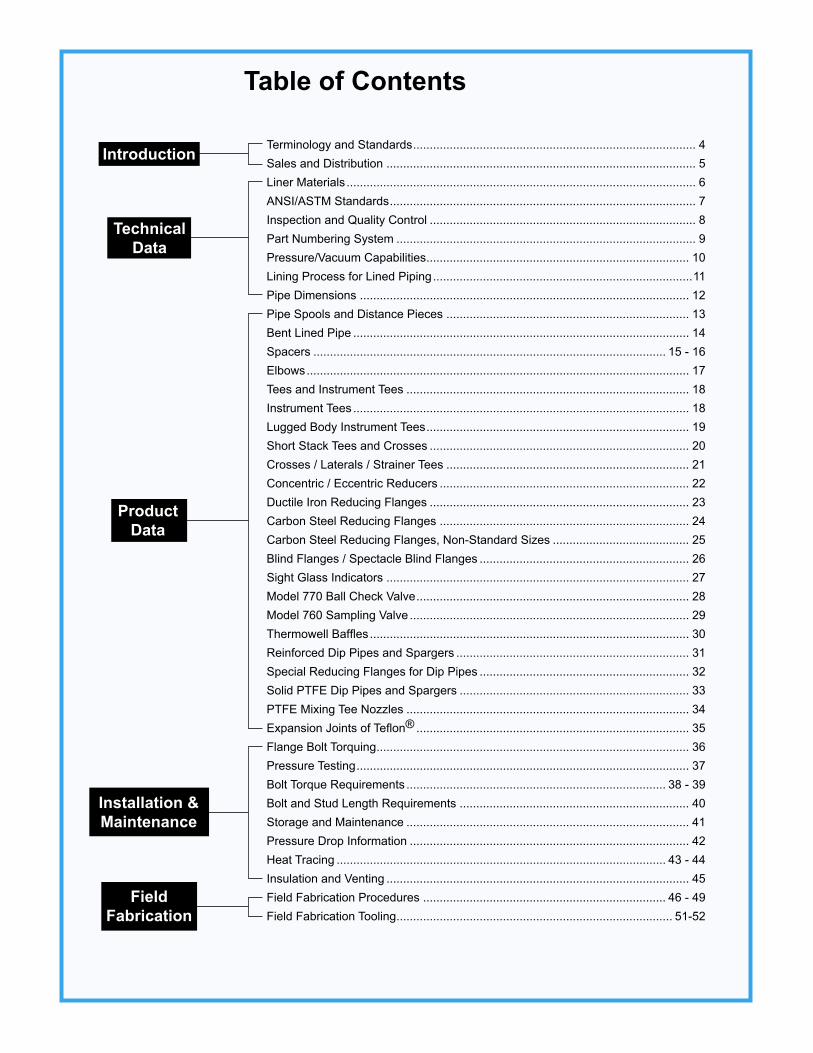
Terminology and Standards ..................................................................................... 4Sales and Distribution ............................................................................................. 5Liner Materials ......................................................................................................... 6ANSI/ASTM Standards ............................................................................................ 7Inspection and Quality Control ................................................................................ 8Part Numbering System .......................................................................................... 9Pressure/Vacuum Capabilities ............................................................................... 10Lining Process for Lined Piping ..............................................................................11Pipe Dimensions ................................................................................................... 12 Pipe Spools and Distance Pieces ......................................................................... 13 Bent Lined Pipe ..................................................................................................... 14 Spacers .......................................................................................................... 15 - 16Elbows ................................................................................................................... 17Tees and Instrument Tees ..................................................................................... 18Instrument Tees ..................................................................................................... 18Lugged Body Instrument Tees ............................................................................... 19Short Stack Tees and Crosses .............................................................................. 20Crosses / Laterals / Strainer Tees ......................................................................... 21Concentric / Eccentric Reducers ........................................................................... 22Ductile Iron Reducing Flanges .............................................................................. 23Carbon Steel Reducing Flanges ........................................................................... 24Carbon Steel Reducing Flanges, Non-Standard Sizes ......................................... 25Blind Flanges / Spectacle Blind Flanges ............................................................... 26Sight Glass Indicators ........................................................................................... 27Model 770 Ball Check Valve .................................................................................. 28Model 760 Sampling Valve .................................................................................... 29Thermowell Baffles ................................................................................................ 30Reinforced Dip Pipes and Spargers ...................................................................... 31Special Reducing Flanges for Dip Pipes ............................................................... 32Solid PTFE Dip Pipes and Spargers ..................................................................... 33PTFE Mixing Tee Nozzles ..................................................................................... 34Expansion Joints of Teflon® .................................................................................. 35Flange Bolt Torquing .............................................................................................. 36Pressure Testing .................................................................................................... 37Bolt Torque Requirements .............................................................................. 38 - 39Bolt and Stud Length Requirements ..................................................................... 40Storage and Maintenance ..................................................................................... 41Pressure Drop Information .................................................................................... 42Heat Tracing ................................................................................................... 43 - 44 Insulation and Venting ........................................................................................... 45Field Fabrication Procedures ......................................................................... 46 - 49Field Fabrication Tooling ................................................................................... 51-52
Table of Contents

4
PTFE Polytetrafluoroethylene, manufactured by DuPont under the trade name Teflon®, is the only PTFE usedby PSI.
PFA Perfluoroalkoxy, manufactured by DuPont under the trade name of Teflon®.
PVDF Polyvinylidene Fluoride, manufactured by Arkema under the name Kynar® and Kynar Flex®.
PP Polypropylene
ETFE Ethylenetetrafluoroethylene, manufactured by DuPont under the trade name Tefzel®, is the only ETFEused by PSI.
NPS Nominal Pipe Size
DI Cast ductile iron
FS Forged steel
CS Cast steel
Full Vacuum 29.6 inches of mercury
ANSI American National Standards Institute
ASTM American Society for Testing and Materials
F1545 ASTM consolidated plastic lined piping standards
A395 ASTM standard pertaining to ferritic ductile iron
A105 ASTM standard pertaining to forged steel
A216 ASTM standard pertaining to cast steel (grade WCB)
INDUSTRY STANDARD LINER COLORATION
PTFE White
PVDF Black as standard. Available unpigmented.
PP Orange as standard. Available unpigmented.
PFA Natural - off white
ETFE Natural - shiny, milky white
Terminology and Standards

5
6
Our Distributors
on-site product and/or fabrication training.
PSI has a well-established network of stocking and fabricating distributors throughout North America. This extensivenetwork of distribution channels offers our customers local and personalized service, regardless of location.
Our distributors are not just order takers. Many of them have over 35 years of lined pipe experience and all are experienced
Factory support is available in the form of bill-of-material take-offs, technical service, and testing. We can also provide in-house or
in the technology of fluid handling and how plastic lined pipe can be used to solve fluid handling problems safely andeconomically. All of our distributors are dedicated to providing unmatched customer service. Additional involvement with, andexperience in related products results in a team of professionals able to assist in any specialized project.
To find a local distributor, log onto www.edlonpsi.com or contact our Customer Service Center at (828) 724-2430.
PSI Headquarters and Manufacturing in Marion, NC
Sales and Distribution

6
PTFE (Polytetrafluoroethylene) PTFE, the most commonly used fluoropolymer, has excellent high- temperature corrosion resistance to virtu-ally all chemicals except elemental fluorine and molten alkali metals. In addition, PTFE possesses unusual non-stick properties which can reduce or eliminate the buildup of deposits on the pipe walls. Service temperatures in pressure piping systems range from -20°F (-29°C) to 450°F (230°C).
PFA (Perfluoroalkoxy) PFA exhibits chemical resistance virtually identical to PTFE. Suitable for service from -20°F to 450°F, PFA is a fluorinated thermoplastic known for its ultra-pure capabilities. PFA provides supe-rior creep resistance at high temperature, excellent low temperature toughness and exceptional flame resistance.
ETFE (Tefzel®, ethylene tetrafluoroethylene) Tefzel® combines mechanical toughness with out-standing chemical resistance that approaches Teflon®. Effective from -20°F to 300°F, Tefzel is easily processed and known for its high energy radiation resistance.
PVDF (Polyvinylidene Fluoride) PVDF has excellent resistance to many chemicals, including halogens and strong oxidants. PVDF exhibits excellent abrasion and permeation resistance. As PSI uses both the homopolymer and copolymer resins, the PVDF lined system is rated from 0°F (-29°C) to 275°F (135°C). Because PVDF is only partially fluorinated, its chemical resistance is affected by temperature and concentration of liquids and gases.
PP (Polypropylene) The PP homopolymer PSI uses has good corro-sion resistance, low moisture absorption, and good mechanical properties. Since its chemical resistance is greatly affected by the concentration and tempera-ture of the conveyed fluid, its use in pressure piping systems is generally limited from 0°F (-16°C) to 225°F (107°C).
Liner Materials
Pipe Dimensions)lanimon(.ni,snoisnemiDepiP
eziS)SPN( DO
ssenkcihTllaW
04.hcS 03.hcS 02.hcS
5. 048.0 901.0
--
--
57. 050.1 311.0
1 513.1 331.0
5.1 009.1 541.0
2 573.2 451.0
5.2 578.2 302.0
3 005.3 612.0
4 005.4 732.0
6 526.6 082.0
8 526.8 223.0 772.0
01 057.01--
703.0
21 057.21 033.0 052.0
PLASTIC LINER DATA
PTFE = polytetrafluoroethylenePFA = perfluoroalkoxy
PP = polypropylene
Gray withBlack Lettering
PVDF = polyvinylidene fluorideETFE = ethylene tetrafluoroethylene
1Max. allowable temperature depend on the specific contact chemicals. 210” - 12” non-vacuum pipe and fittings band is red with black letters.3Available unpigmented as a special option.
scitsiretcarahCreniL EFTP AFP PP FDVP)remylopomoh(
FDVP)remylopoc( EFTE
F°,egnaRerutarepmeTecivreS 1 F°054otF°02- F°054otF°0 F°522otF°0 F°572otF°0 F°572otF°02- F°003otF°02-
roloCreniL etihW larutaN egnarO 3 kcalB 3 kcalB 3 larutaN
dnaBnoitacifitnedIreniLforoloC htiwetihWgniretteLkcalB 2
/wegnarOgniretteLkcalB
etihW/wkcalBgniretteL
etihW/wkcalBgniretteL
etihW/wyarGgniretteL
epiPfonoisnapxElamrehTfotneiciffeoC/.ni/.ni,gniniLotroirPreniL F° 01x5.5 5- 01x8.7 5- 01x8.4 5- 01x6.6 5- 01x8.7 5- 01x4.7 5-
tivitcudnoClamrehT y,reniLfo)rotcaF"K"( B -.tf.qs-.rh/.ni-UT F° 7.1 3.1 8.0 9.0 81.1 56.1
isp,dleiYtareniLfohtgnertSelisneT 000,4-000,3 005,4-008,3 005,4-000,4 000,6-000,5 005,5-005,4 0076
%,dleiYtareniLfonoitagnolE 053-052 053-003 31-01 01-8 02-01 003-051
isp,dleiYtareniLfohtgnertSevisserpmoC 007,1 005,3 000,8-005,5 000,61-000,01 0058-0005 005,2
reniLfoytivarGcificepS 91.2-41.2 71.2-21.2 29.0-09.0 87.1-57.1 87.1-67.1 27.1-07.1
Flange Dimensions)lanimon(.ni,snoisnemiDegnalF
eziS)SPN(
051ssalC 003ssalC
DO ssenkcihT .aiDdna).oN(seloHtloBfo
elcriCtloBretemaiD DO ssenkcihT .aiDdna).oN(
seloHtloBfoelcriCtloBretemaiD
5. 2/13 61/7 8/5)4( 8/32 4/33 61/9 8/5)4( 8/52
57. 8/73 2/1 8/5)4( 4/32 8/54 8/5 4/3)4( 4/13
1 4/14 61/9 8/5)4( 8/13 8/74 61/11 4/3)4( 2/13
5.1 5 61/11 8/5)4( 8/73 8/16 61/31 8/7)4( 2/14
2 6 4/3 4/3)4( 4/34 2/16 8/7 4/3)8( 5
5.2 7 8/7 4/3)4( 2/15 2/17 1 8/7)8( 8/75
3 2/17 61/51 4/3)4( 6 4/18 8/11 8/7)8( 8/56
4 9 61/51 4/3)8( 2/17 01 4/11 8/7)8( 8/77
6 11 1 8/7)8( 2/19 2/121 61/71 8/7)21( 8/501
8 2/131 8/11 8/7)8( 4/311 51 8/51 1)21( 31
01 61 61/31 1)21( 4/141 2/171 8/71 8/11)61( 4/151
21 91 4/11 1)21( 71 2/102 2 4/11)61( 4/371

7
Liners: PTFE — Polytetrafluoroethylene ASTM D4894, D4895 PFA — Perfluoroalkoxy ASTM D3307 PVDF — Polyvinylidene Fluoride ASTM D3222, D5575 PP — Polypropylene Type II Copolymer ASTM D4101
Pipe: 1" through 4" size, Schedule 40 Carbon Steel per ASTM A587 ERW 6" through 8" size, Schedule 40 Carbon Steel per ASTM A53, Grade B Type E 10" size, Schedule 30 Carbon Steel per ASTM A53, Grade B Type E 12" size, Schedule 20 Carbon Steel per ASTM A53, Grade B Type E
Flanges: Lap-joint, 1" through 12" size, Ductile Iron ASTM A395, dimensions per ANSI B16.42 Class 150 Lap-joint, 1" through 12" size, Forged Steel ASTM A105, dimensions per ANSI B16.5 Class 150
Fitting Types: Fabricated Carbon Steel: components per ASTM A587, A53 & A234 as specified on individual drawings. Dimensions per ANSI 16.5 Class 150. Flanges rotating lap joint or fixed as specified above. Ductile Iron Casting (60-40-18) per ASTM A395. Cast Steel per ASTM A216 Gr. WCB. Standard fittings dimensions per ANSI B16.5 Class 150.
Fabrication Pipe and Fittings Dimension Tolerance, in. Length and Centerline Dimensions ± 1/8" Fixed Flange Bolt Hole Alignment ± 1/16" Flange Perpendicularity 3/32 in/ft of nom. pipe (with Pipe Centerline) diameter
Tolerances:
PSI ANSI/ASTM Standards
Pipe and fittings manufactured by PSI are in full compliance with:
ASTM F1545, Standard Specification for Plastic-Lined Ferrous Metal Pipe, Fittings, and Flanges
This specification covers all aspects of Plastic Lined Piping Products including:
Approved ASTM designations of resin used to manufacture liner Approved ASTM designations of materials of construction of housings and flanges Minimum dimensional requirements Required qualification testing and proof-testing procedures
PSI products also meet the following specifications/requirements:
Note: PP and PVDF-lined fittings are normally supplied with fixed flanges

8
Diameter – Inches (Nominal) 1 11/2 2 3 4 6 8 10 12
PTFE FULL VACUUM RATED Liner Thickness (in.) .130 .150 .160 .160 .160 .275 .310 .320 .425 Vacuum (in. Hg) Full Full Full Full Full Full Full Full Full Temperature (˚F) 450 450 450 450 450 450 450 450 450 NON VACUUM RATED Liner Thickness (in.) - - - - - - - - - - - - - - .200 .200 Vacuum (in. Hg) Non Non Vacuum Vacuum PP Liner Thickness (in.) .135 .160 .175 .175 .210 .220 .220 .320 .380 Vacuum (in. Hg) Full Full Full Full Full Full Full Full Full Temperature (˚F) 225 225 225 225 225 225 225 225 225
PFA Liner Thickness (in.) .113 .114 .114 .130 .150
.145 .140
Vacuum (in. Hg) Full Full Full Full Full
Non Non - - - - Vacuum Vacuum Temperature (˚F) 450 450 450 450 450
PVDF Liner Thickness (in.) .125 .125 .125 .125 .145 .160 .185 Vacuum (in. Hg) Full Full Full Full Full Full Full - - - - Temperature (˚F) 275 275 275 275 275 275 275
Note 1: All vacuum data reflects testing done per ASTM F1545.Note 2: 1" - 8" fittings meet or exceed pipe liner thickness and vacuum ratings for same size and liner material. Vacuum
ratings for some 10" and larger fittings may have vacuum limitations. Consult factory.Note 3: Vacuum ratings may not apply for special angle elbows, sight flow indicators and laterals, crosses and eccentric
reducers that are 6" and above. Consult factory.Note 4: Certain chemicals may affect vacuum ratings. Consult factory.
• Each lined pipe and fitting shall be subjected to a 18,000-volt electrostatic and/or hydro test-ing, per ASTM 1545, as part of the finish inspection. A visible or audible spark at the probe from an electrical contact to the housing or evidence of leakage at a vent hole indicates the presence of a defect in the liner and shall be cause for rejection.
• The sealing surface of the liner shall be free of any defects that would impair the sealing effective-ness. Any imperfection will not exceed 10% of the flare thickness.
• Wooden end protectors are used to protect the plastic faces of flanged pipe and fittings. End protectors should stay in place until just prior to installation.
• Flanged pipe and fittings are labeled with a PSI sticker
located on the wooden end protectors, which identifies the plastic liner type, the flange material, and spool length.
• A colored plastic band is placed on all pipe and fittings to identify the PSI material and the liner type on the exterior of the pipe.
• Plastic caps will be used to protect the ends on field flare product.
RELATIONSHIPS, BY LINING MATERIAL, BETWEEN VACUUM RATING AND TEMPERATURE FOR STANDARD LINED PIPE
Inspection and Quality Control
9
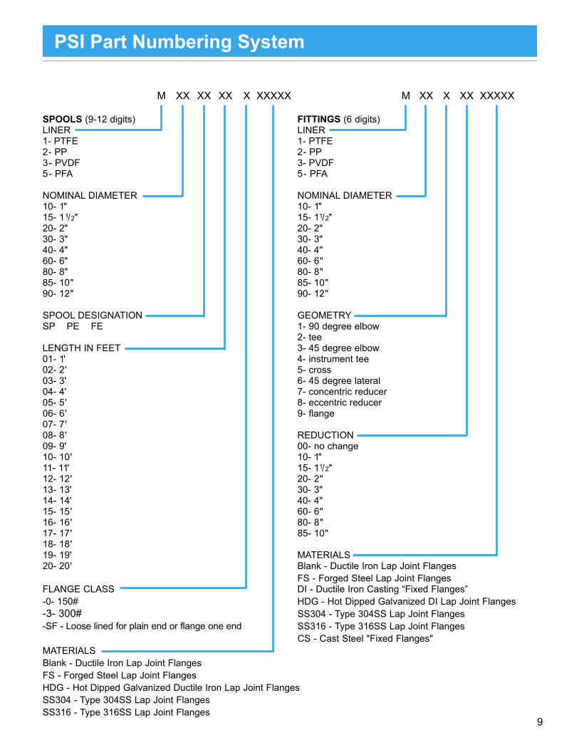
M XX XX XX X XXXXX M XX X XX XXXXX
SPOOLS (9-12 digits) FITTINGS (6 digits)LINER LINER1- PTFE 1- PTFE2- PP 2- PP3- PVDF 3- PVDF5- PFA 5- PFA
NOMINAL DIAMETER NOMINAL DIAMETER10- 1" 10- 1"15- 1 1/2" 15- 11/2"20- 2" 20- 2"30- 3" 30- 3"40- 4" 40- 4"60- 6" 60- 6"80- 8" 80- 8"85- 10" 85- 10"90- 12" 90- 12"
SPOOL DESIGNATION GEOMETRYSP PE FE 1- 90 degree elbow 2- teeLENGTH IN FEET 3- 45 degree elbow01- 1' 4- instrument tee02- 2' 5- cross03- 3' 6- 45 degree lateral04- 4' 7- concentric reducer05- 5' 8- eccentric reducer06- 6' 9- flange07- 7'08- 8' REDUCTION09- 9' 00- no change10- 10' 10- 1"11- 11' 15- 11/2"12- 12' 20- 2"13- 13' 30- 3"14- 14' 40- 4"15- 15' 60- 6"16- 16' 80- 8"17- 17' 85- 10"18- 18' 19- 19' MATERIALS20- 20' Blank - Ductile Iron Lap Joint Flanges FS - Forged Steel Lap Joint FlangesFLANGE CLASS DI - Ductile Iron Casting “Fixed Flanges”-0- 150# HDG - Hot Dipped Galvanized DI Lap Joint Flanges-3- 300# -SF - Loose lined for plain end or flange one end
MATERIALSBlank - Ductile Iron Lap Joint FlangesFS - Forged Steel Lap Joint FlangesHDG - Hot Dipped Galvanized Ductile Iron Lap Joint FlangesSS304 - Type 304SS Lap Joint FlangesSS316 - Type 316SS Lap Joint Flanges
PSI Part Numbering System
SS304 - Type 304SS Lap Joint FlangesSS316 - Type 316SS Lap Joint FlangesCS - Cast Steel "Fixed Flanges"

10
The pressure/temperature ratings of 1" to 12" PSI Plastic-Lined Piping Products conform to standard ANSI codesand specifications per the appropriate metallurgy. See Figure 1. The pressure/temperature ratings for l ined piping with ANSI B16.5 Class 300 flanges are adjusted to account for plastic raised faces on pipe and fittings, and are lower than actual ANSI B16.5 Class 300 pressure/temperature ratings.
PVDF (1" - 8") and PP (1" - 12") pipe and fittings have been full vacuum rated at their maximum service temperature and can beused at full vacuum within their operating temperature ranges. Standard 1" - 12" PTFE pipe and fittings are available to provideFull Vacuum / 450°F performance, if so specified. Some pipe and fittings may have a reduced vacuum rating. 1" - 4" PFA-lined pipe and fittings are rated for full vacuum to 450 F. 6" and 8" PFA-lined pipe and fittings are non-vacuum rated.
Figure 1: Working pressures for PSI plastic-lined pipe and fittings (includes PTFE-lined stainless steel pipe)
1. Class 150 stainless steel (Steel Flanges) (Type 304L) ANSI B16.5.2. Class 150 ductile iron/plastic lined ANSI B16.42.3. Class 150 cast steel/plastic lined ANSI B16.5.4. Class 150 stainless steel/plastic (Steel Flanges) lined ANSI B16.5.5. Class 150 carbon steel ANSI B16.5.6. Class 300 cast steel/plastic lined. 7. Class 300 stainless steel/plastic (Steel Flanges) lined.8. Class 300 stainless steel (Steel Flanges) (Type 304L) ANSI B16.5.9. Class 300 cast steel ANSI B16.5.
Maximum temperatures may be reduced depending on the aggressiveness of the fluid being handled.
-18 10 38 65 93 121 149 177 204 232 oC
6.9
oF
13.8
55.1
48.3
41.4
34.5
27.6 Bar(g)
20.7
Liner Limits1 PP PVDF PTFE/PFA
0 50 100 150 200 250 300 350 400 450
800
700
600
500
400
Pres
sure
(psi
g)
300
200
100
0
1 23
4 5
6 7
8
9
Curves
Pressure/Vacuum Capabilities of Pipe and Fittings
Note 1: All vacuum data reflects testing done per ASTM F1545.
Note 2: 1" - 8" fittings meet or exceed pipe liner thick-ness and vacuum ratings for same size and liner material. Vacuum ratings for some 10" and larger fittings may have vacuum limita-tions. Consult factory.
Note 3: Vacuum ratings may not apply for special angle elbows, sight flow indicators and later-als, crosses and eccentric reducers that are 6" and above. Consult factory.
Note 4: Certain chemicals may affect vacuum ratings. Consult factory.

11
PSI steel pipe and plastio liner act as one integral piece. Combining dissimilar materials with very differentrates of thermal expansion, our precision lining process locks the isostatically molded liner into the pipe housing,making it full-vacuum rated throughout the temperature range.
The lining process positively locks the plastic liner in the metal pipe housing while effectively relieving stresses that couldcause unwanted liner movement in service.
Lining Process:
• Incoming lots of resin are analyzed in our Quality Assurance laboratory for conformance to established raw materialspecifications.
• The liner is processed under controlled conditions to a size somewhat larger than the I.D. of the steel housing intowhich it will be installed. It is then thoroughly inspected for conformance to design specifications. Next, the lineris subjected to a battery of quality tests designed to ensure liner integrity.
• The liner is then drawn through a sizing die at carefully controlled draw rates which results in a calculated reduction inthe oustide diameter.
• A programmed heating cycle relaxes the liner inside the steel housing, resulting in a snug liner fit. Design allowancesare incorporated in this procedure to eliminate undesirable stresses in the finished product.
• Both liner ends of the pipe spool are then flared. Temperature, time and pressure are carefully monitored.• The finished pipe is then tested in accordance with ASTM F1545 standards.
The PSI lining process provides lined pipe with dimensional stability under vacuum, pressure, and thermal cyclingconditions, which prevents liner buckling and cracked flares within operational limits.
Drawing and Sizing
PSI Field Flare Pipe
Field Flare (FF) pipe is available Flange x Plain End or PlainEnd x Plain End pipe with movable liner for distributor or end-user fabrication1 with the following features:
• PSI manufactures Field Flare pipe utilizing the the same lining process as factory-finished pipe, but the process is modified to result in a movable liner.
• The liner can be removed from the pipe, allowing the fabricator a wide variety of flange options, including the PSI field flare flange, all types of weld flanges, and lap joint flanges.
• PSI Field Flare pipe has the same performance characteristics of the factory-finished pipe, including full vacuum capability.
• Available in PTFE, PP, PVDF, And PFA in the same sizes as factory-finished spools.
• Housings are available in CS or SS.
1 - Special fabrication tooling and training required.
Lining Process for Factory and Field Flare Piping

12
Steel Pipe Liner Thickness, in. Weight (lbs.)
Nominal
First Ea.Add’l. Size O.D. Wall PTFE PP PVDF PFA Foot Foot
1 1.315 .133 .130 .135 .125 .113 7 2 11/2 1.900 .145 .150 .160 .125 .114 9 3 2 2.375 .154 .160 .175 .125 .114 15 4 3 3.500 .216 .160 .175 .125 .130 26 8 4 4.500 .237 .160 .210 .145 .150 38 12 6 6.625 .280 .275 .220 .160 .145 60 21 8 8.625 .322 .310 .220 .185 .140 94 32
PSI LINED PIPE DIMENSIONS
Also Available as an Option: • 304/316 stainless steel • Vent couplings
(including ”L” grade) lined pipe • Jacketed construction with stainless or hot-dipped • 300# flanges galvanized flanges. • DIN flanges
STEEL PIPE DIMENSIONS
Nominal Wall Thicknesses, in.
Nominal Outside Sched. Sched. Sched. Pipe Size Dia. 20 30 40 1 1.315 — — .133 11/2 1.900 — — .145 2 2.375 — — .154 3 3.500 — — .216 4 4.500 — — .237 6 6.625 — — .280 8 8.625 — — .322 10 10.750 — .307 — 12 12.750 .250 — —
Pipe Sizes PSI plastic-lined metal systems are available from 1/2" through 12". All types of PSI plastic-lined pipe can easily be field fabricated. Housing Materials Various metals (carbon steel, 304 and 316 stainless steel including “L” grades, and other alloys) are available.Flanges ANSI Class 150 and Class 300, as well as DIN rotating flanges are available in a variety of materials. Ductile iron is the stan-dard flange material. Hot dipped galvanized, stainless and forged steel can be substituted with pricing on request. Vent Extensions (1/8" or 1/4" half couplings can be welded over ventholes prior to lining.)Consider For: 1. Sacrificial nipples for use in Halogen services. Extremely small in mole- cule size, Chlorine, Bromine and Fluorine have a tendency to perme- ate through the plastic liner and form acids at the vent hole where they see moisture. Vent extensions trans- fer the acid attack from the body of the pipe to the remote nipple end, thereby extending pipe life. 2. Extensions to route permeated gasses past pipe insulation.3. Dual containment leak sensor ports.4. Vacuum taps Coating Systems: Gray two-part epoxy prim-er is standard. If special paint or blast profile is required, this can be applied at the factory with pricing on application.
Lined Pipe and Fittings
A complete line of standard and custom flanged fittings, lined with PTFE, ETFE, PFA, PVDF and PP is available. Certain sizes and geometries may not be available in all liners. Please consult the factory. PP/PVDF/PFA fittings normally have fixed flanges.Many Class 300 fittings are available in two lay lengths. Most PTFE-lined fittings are standard ANSI Class 150 housings with Class 300 flanges. Some Class 300 flanged PTFE lined fittings are available
with ANSI 300 centerline-face dimensions. PP and PVDF ANSI 300 fittings have ANSI 300 lb lay lengths. Please note: the increased number of bolt holes on the 150# lay length style may make fit up difficult. Tapped holes have been incorporated to accommo-date.
Please offset tapped holes during installation to allow correct torquing.
LINED PIPE
LINED FITTINGS
10 (FVR) 10.750 .307 .320 .320 — — 128 39 10 (NVR) .200 — — — 125 36 12 (FVR) 12.750 .250 .425 .380 — — 180 50 12 (NVR) .200 — — — 176 36
FVR = Full Vacuum Rated LinerNVR = Non-Vacuum Rated Liner
13
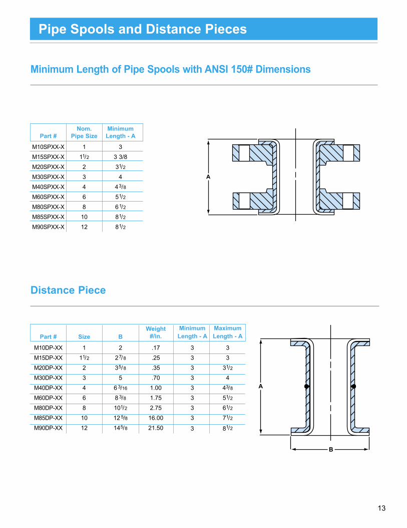
Weight Minimum Maximum Part # Size B #/in. Length - A Length - A
M10DP-XX 1 2 .17 3 3
M15DP-XX 11/2 27/8 .25 3 3
M20DP-XX 2 35/8 .35 3 31/2
M30DP-XX 3 5 .70 3 4
M40DP-XX 4 6 3/16 1.00 3 43/8
M60DP-XX 6 8 3/8 1.75 3 51/2
M80DP-XX 8 101/2 2.75 3 61/2
M85DP-XX 10 12 5/8 16.00 3 71/2
M90DP-XX 12 145/8 21.50 3 81/2
Nom. Minimum Part # Pipe Size Length - A
M10SPXX-X 1 3
M15SPXX-X 11/2 3 3/8
M20SPXX-X 2 31/2
M30SPXX-X 3 4
M40SPXX-X 4 43/8
M60SPXX-X 6 51/2
M80SPXX-X 8 61/2
M85SPXX-X 10 81/2
M90SPXX-X 12 81/2
Minimum Length of Pipe Spools with ANSI 150# Dimensions
Distance Piece
A
A
B
Pipe Spools and Distance Pieces
14
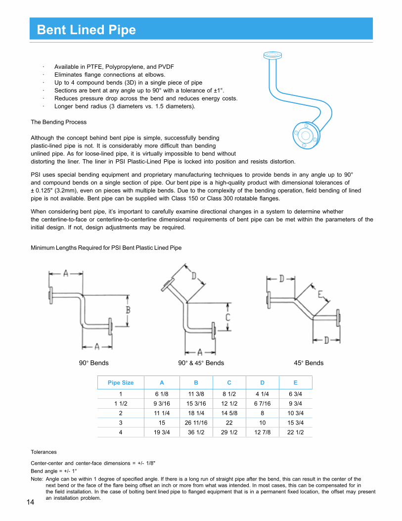
Pipe Size A B C D E
1 6 1/8 11 3/8 8 1/2 4 1/4 6 3/41 1/2 9 3/16 15 3/16 12 1/2 6 7/16 9 3/4
2 11 1/4 18 1/4 14 5/8 8 10 3/43 15 26 11/16 22 10 15 3/44 19 3/4 36 1/2 29 1/2 12 7/8 22 1/2
Bent Lined Pipe
· Eliminates flange connections at elbows.· Available in PTFE, Polypropylene, and PVDF
· Up to 4 compound bends (3D) in a single piece of pipe· Sections are bent at any angle up to 90° with a tolerance of ±1°.· Reduces pressure drop across the bend and reduces energy costs.· Longer bend radius (3 diameters vs. 1.5 diameters).
The Bending Process
Although the concept behind bent pipe is simple, successfully bendingplastic-lined pipe is not. It is considerably more difficult than bendingunlined pipe. As for loose-lined pipe, it is virtually impossible to bend withoutdistorting the liner. The liner in PSI Plastic-Lined Pipe is locked into position and resists distortion.
PSI uses special bending equipment and proprietary manufacturing techniques to provide bends in any angle up to 90°and compound bends on a single section of pipe. Our bent pipe is a high-quality product with dimensional tolerances of ± 0.125" (3.2mm), even on pieces with multiple bends. Due to the complexity of the bending operation, field bending of linedpipe is not available. Bent pipe can be supplied with Class 150 or Class 300 rotatable flanges.
When considering bent pipe, it’s important to carefully examine directional changes in a system to determine whetherthe centerline-to-face or centerline-to-centerline dimensional requirements of bent pipe can be met within the parameters of theinitial design. If not, design adjustments may be required.
Minimum Lengths Required for PSI Bent Plastic Lined Pipe
90° Bends 90° & 45° Bends 45° Bends
Tolerances
Center-center and center-face dimensions = +/- 1/8"Bend angle = +/- 1°Note: Angle can be within 1 degree of specified angle. If there is a long run of straight pipe after the bend, this can result in the center of the
next bend or the face of the flare being offset an inch or more from what was intended. In most cases, this can be compensated for in the field installation. In the case of bolting bent lined pipe to flanged equipment that is in a permanent fixed location, the offset may present an installation problem.
15
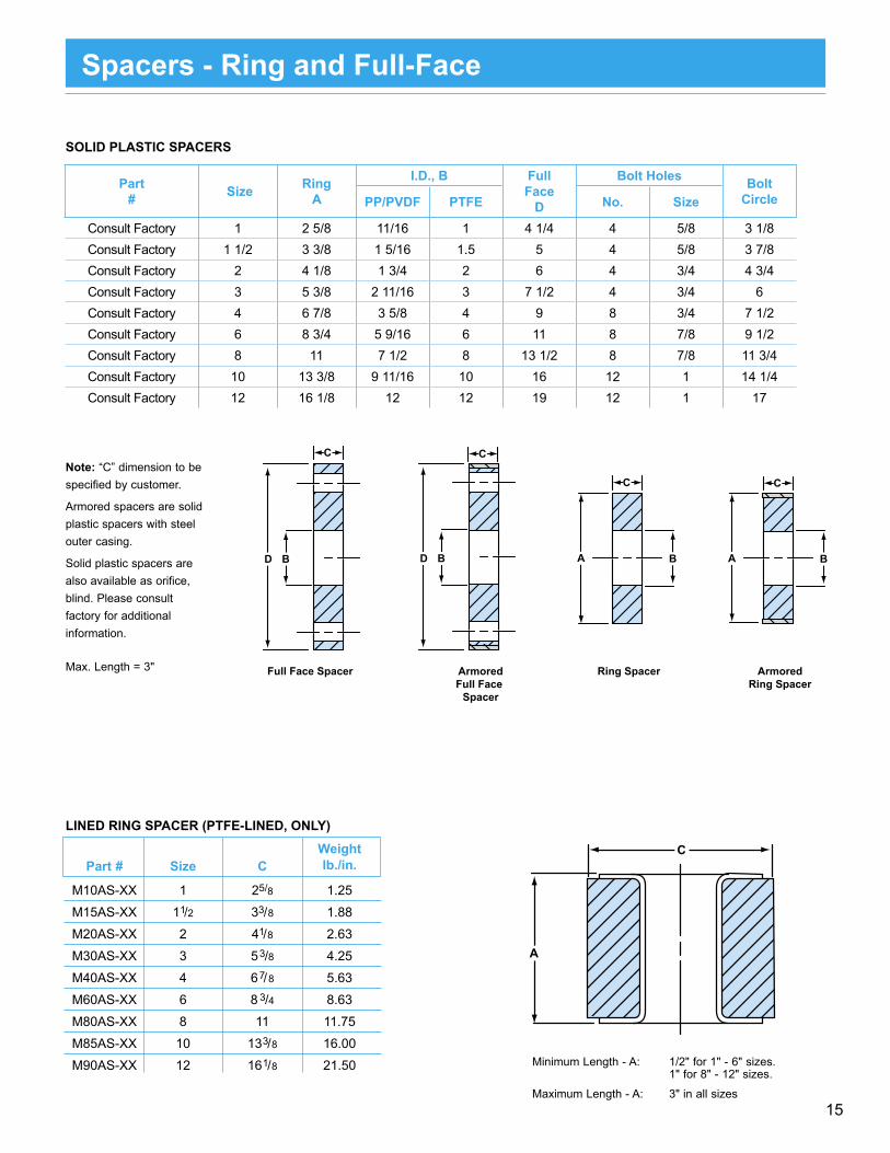
Weight Part # Size C lb./in.
M10AS-XX 1 25/8 1.25
M15AS-XX 11/2 33/8 1.88
M20AS-XX 2 41/8 2.63
M30AS-XX 3 53/8 4.25
M40AS-XX 4 67/8 5.63
M60AS-XX 6 8 3/4 8.63
M80AS-XX 8 11 11.75
M85AS-XX 10 133/8 16.00
M90AS-XX 12 161/8 21.50 Minimum Length - A: 1/2" for 1" - 6" sizes. 1" for 8" - 12" sizes.
Maximum Length - A: 3" in all sizes
A
C
Part # Size Ring
A
I.D., B FullFace
D
Bolt Holes BoltCirclePP/PVDF PTFE No. Size
Consult Factory 1 2 5/8 11/16 1 4 1/4 4 5/8 3 1/8Consult Factory 1 1/2 3 3/8 1 5/16 1.5 5 4 5/8 3 7/8Consult Factory 2 4 1/8 1 3/4 2 6 4 3/4 4 3/4Consult Factory 3 5 3/8 2 11/16 3 7 1/2 4 3/4 6Consult Factory 4 6 7/8 3 5/8 4 9 8 3/4 7 1/2Consult Factory 6 8 3/4 5 9/16 6 11 8 7/8 9 1/2Consult Factory 8 11 7 1/2 8 13 1/2 8 7/8 11 3/4Consult Factory 10 13 3/8 9 11/16 10 16 12 1 14 1/4Consult Factory 12 16 1/8 12 12 19 12 1 17
Note: “C” dimension to be specified by customer.
Armored spacers are solid plastic spacers with steel outer casing.
Solid plastic spacers are also available as orifice, blind. Please consult factory for additional information.
Max. Length = 3" Full Face Spacer ArmoredRing Spacer
Ring Spacer
A B
C
ArmoredFull Face
Spacer
D B
C
A B
C
D B
C
Spacers - Ring and Full-Face
SOLID PLASTIC SPACERS
LINED RING SPACER (PTFE-LINED, ONLY)
16
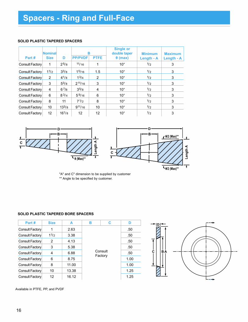
Part # Size A B C D
Consult Factory 1 2.63 .50 Consult Factory 11/2 3.38 .50 Consult Factory 2 4.13 .50 Consult Factory 3 5.38 .50 Consult Factory 4 6.88 .50 Consult Factory 6 8.75 1.00 Consult Factory 8 11.00 1.00 Consult Factory 10 13.38 1.25 Consult Factory 12 16.12 1.25
Single or Nominal B double taper Minimum Maximum Part # Size D PP/PVDF PTFE 0 (max) Length - A Length - A Consult Factory 1 25/8 11/16 1 10° 1/2 3
Consult Factory 11/2 33/8 15/16 1.5 10° 1/2 3 Consult Factory 2 41/8 13/4 2 10° 1/2 3 Consult Factory 3 53/8 211/16 3 10° 1/2 3 Consult Factory 4 6 7/8 35/8 4 10° 1/2 3 Consult Factory 6 8 3/4 5 9/16 6 10° 1/2 3 Consult Factory 8 11 71/2 8 10° 1/2 3Consult Factory 10 133/8 911/16 10 10° 1/2 3Consult Factory 12 161/8 12 12 10° 1/2 3
"A" and C" dimension to be supplied by customer ** Angle to be specified by customer.
DB
C
0 (Max)**
BD
C
0/2 (Max)**
0/2 (Max)**
Leng
th A
Leng
th A
Spacers - Ring and Full-Face
D
C B A
Available in PTFE, PP, and PVDF
SOLID PLASTIC TAPERED SPACERS
SOLID PLASTIC TAPERED BORE SPACERS
ConsultFactory

17
B
B
45° Elbow
45°
90° ElbowA
A
90° Reducing Elbow
A
A
Note: Representative graphics show rotating flanges. PP/PVDF/PFA fittings are normally castings with fixed flanges.
Elbows
45 DEGREE ELBOWS
90 DEGREE ELBOWS
REDUCING 90 DEGREE ELBOWS (150 lb, only)
NOTE: 10" and 12" Polypropylene-lined fittings are made with glass-filled resin and are not recommended for hydrofluoric acid or sodium hydroxide service
Part # Size A Wt.M15110 1 1/2 x 1 4 7.0M20110 2 x 1 4 1/2 9.3M20115 2 x 1 1/2 4 1/2 11.8M30120 3 x 1 5 1/2 14.9M30115 3 x 1 1/2 5 1/2 16.9M30120 3 x 2 5 1/2 19.0M40110 4 x 1 6 1/2 22.10M40115 4 x 1 1/2 6 1/2 24.8M40120 4 x 2 6 1/2 26.5M40130 4 x 3 6 1/2 33.0M60120 6 x 2 8 44.0M60130 6 x 3 8 45.0M60140 6 x 4 8 52.0M80140 8 x 4 9 86.0M80160 8 x 6 9 89.0
Part # Size B (150 lb. Flanged)
B (300 lb Flanged)*
Wt.
M10300 1 1 3/4 2 1/4 4.5M15300 1 1/2 2 1/4 2 3/4 7.0M20300 2 2 1/2 3 10.5M30300 3 3 3 1/2 21.5M40300 4 4 4 1/2 37.0M60300 6 5 5 1/2 63.0M80300 8 5 1/2 6 110.0M85300 10 6 1/2 - - 160.0M90300 12 7 1/2 - - 205.0
Part # Size B (150 lb. Flanged)
B (300 lb Flanged)*
Wt.
M10100 1 3 1/2 4 5.0M15100 1 1/2 4 4 1/2 8.5M20100 2 4 1/2 5 14.0M30100 3 5 1/2 6 26.0M40100 4 6 1/2 7 41.0M60100 6 8 8 1/2 75.0M80100 8 9 10 125.0M85100 10 11 - - 200.0M90100 12 12 - - 245.0
Reducing 90 deg. elbows not available in PTFE.
PTFE-lined 300 lb flanged 90 deg elbows are avail-able with 150 lb lay lengths in 1" - 6" sizes, only.
* PP/PVDF available in 1" - 6" only
* PP/PVDF available in 1" - 6" only

18
STANDARD TEE Part # Size A Wt. M10200 1 31/2 10.0
M15200 11/2 4 14.0
M20200 2 41/2 19.0
M30200 3 51/2 39.0
M40200 4 61/2 67.0
M60200 6 8 120.0
M80200 8 9 180.0
M85200 10 11 219.0
M90200 12 12 318.0
INSTRUMENT TEES, 150 LB FLANGED
B B B Part # Size A 150# Wt. Size A* 150# Wt. Size A 150# Wt. M104XX 1 x 1 2 31/2 3.7 – – – – – – – –
M154XX 11/2 x 1 2 4 5.1 11/2 x 11/2 3* 4 8.3 – – – –
M204XX 2 x 1 2 41/2 6.6 2 x 11/2 3* 41/2 11.0 2 x 2 4 41/2 17.0
M304XX 3 x 1 2 51/2 9.2 3 x 11/2 3* 51/2 16.0 3 x 2 4 51/2 21.0
M404XX 4 x 1 2 61/2 13.3 4 x 11/2 3* 61/2 22.0 4 x 2 4 61/2 31.0
M604XX 6 x 1 2 8 17.4 6 x 11/2 3* 8 29.0 6 x 2 4 8 38.8
M804XX 8 x 1 2 9 23.6 8 x 11/2 3* 9 38.1 8 x 2 4 9 53.0
M854XX 10 x 1 2 11 38.1 10 x 11/2 3* 11 53.0 10 x 2 4 11 67.0
M904XX 12 x 1 2 12 50.0 12 x 11/2 3* 12 65.2 12 x 2 4 12 80.0
REDUCING TEE* Part # Size A Wt. M152XX 11/2 4 12.2
M202XX 2 41/2 17.0
M302XX 3 51/2 33.0
M402XX 4 61/2 57.0
M602XX 6 8 102.0
M802XX 8 9 167.0
M852XX 10 11 260.0
M902XX 12 12 290.0
A
A
A
Standard TeeA
A
A
Reducing Tee
Tees and Instrument Tees
B
A
Instrument Tee
* For PP/PVDF Instrument Tees With 1 1/2" Branch, "A" Dimension is 4"
NOTE: 10" and 12" Polypropylene-lined fittings are made with glass-filled resin and are not recommended for hydrofluoric acid or sodium hydroxide service
Note: Representative graphics show rotating flanges. PP/PVDF/PFA fittings are normally castings with fixed flanges.
Part # Size A B (PTFE)
B (PP/PVDF)
Wt. Size A B (PTFE, Only)
Wt.
M102XX 1 x 1 2 4 4 3.7 - - - - - - - -M152XX 1 1/2 x 1 2 4 1/2 4 1/2 5.1 1 1/2 x 1 1/2 3 4 1/2 8.3M202XX 2 x 1 2 5 9/16 5 6.6 2 x 1 1/2 3 5 9/16 11.0M302XX 3 x 1 2 6 5/16 6 9.2 3 x 1 1/2 3 6 5/16 16.0M402XX 4 x 1 2 7 1/16 7 13.3 4 x 1 1/2 3 7 1/16 22.0M602XX 6 x 1 2 8 1/16 8 1/2 17.4 6 x 1 1/2 3 8 1/16 29.0M802XX 8 x 1 2 9 5/16 - - 23.6 8 x 1 1/2 3 9 5/16 38.1
PP/PVDF tees are available 300 lb flanged with 300 lb lay lengths in 1" - 6"
* Weights shown are one step reduction.
INSTRUMENT TEES, 300 LB FLANGED
B
A
Instrument Tee
PP/PVDF reducing tees are available 300 lb flanged with 300 lb lay lengths in 1.5" - 4"

19
Lugged Body Instrument Tees
Instrument Tee Size
Branch Size Part # L P T J "H" Holes
No. and Size
"G" Bolt Circle
Diameter
1 1 M10410LFS 2 3 1/2 4 1/4 2 (4) 1/2 - 13 3 1/8
1.51 M15410LFS 2
4 5 2 7/8 (4) 1/2 - 13 3 7/81.5 M15415LFS 4
2
1 M20410LFS 2
4 1/2 6 3 5/8 (4) 5/8 - 11 4 3/41.5 M20415LFS 4
2 M20420LFS 4
3
1 M30410LFS 2
5 1/2 7 1/2 5 (4) 5/8 - 11 61.5 M30415LFS 4
2 M30420LFS 4
4
1 M40410LFS 2
6 1/2 9 6 3/16 (8) 5/8 - 11 7 1/21.5 M40415LFS 4
2 M40420LFS 4
6
1 M60410LFS 2
8 11 8 1/2 (8) 3/4 - 10 9 1/21.5 M60415LFS 4
2 M60420LFS 4
8
1 M80410LFS 2
9 13 1/2 10 5/8 (8) 3/4 - 10 11 3/41.5 M80415LFS 4
2 M80420LFS 4
10
1 M85410LFS 2
11 16 12 3/4 (12) 7/8 - 9 14 1/41.5 M85415LFS 4
2 M85420LFS 4
12
1 M90410LFS 2
12 19 15 (12) 7/8 - 9 171.5 M90415LFS 4
2 M90420LFS 4
L
P
T J
H
G
Available in PTFE / PP / PVDF (PVDF not available in 10"/12")PTFE lugged body instrument tees are supplied with a rotating branch flangePP/PVDF branch flanges are fixed
NOTE: 10" and 12" Polypropylene-lined fittings are made with glass-filled resin and are not recommended for hydrofluoric acid or sodium hydroxide service

20
CARBON STEEL SHORT STACK TEE Part # Size A B Wt. M105SS 1 31/2 1 8.5
M155SS 11/2 4 13/16 12.2
M205SS 2 41/2 2 18.5
M305SS 3 51/2 23/4 33.0
M405SS 4 61/2 31/4 51.0
M605SS 6 8 45/16 85.0
M805SS 8 9 55/16 150.0
CARBON STEEL SHORT STACK CROSS Part # Size A B M102SS 1 31/2 1 9.0
M152SS 11/2 4 13/16 15.0
M202SS 2 41/2 2 21.5
M302SS 3 51/2 23/4 37.0
M402SS 4 61/2 31/4 60.0
M602SS 6 8 45/16 97.0
M802SS 8 9 55/16 160.0
Wt.
C.S. Short Stack Tees and Crosses are PTFE-Lined, only.10" / 12" - Consult Factory
PTFE-Lined Short Stack Tees and Crosses
Short Stack Cross
B
B
A A
B
A A
Short Stack Tee(tapped holes straddle CL)
B
AA
B
AA
DUCTILE IRON SHORT STACK CROSS Part # Size A B M102SS 1 31/2 13/16 9.0
M152SS 11/2 4 115/32 15.0
M202SS 2 41/2 111/16 21.5
M302SS 3 51/2 23/16 37.0
M402SS 4 61/2 211/16 60.0
M602SS 6 8 311/16 99.0
M802SS 8 9 415/16 163.0
M852SS 10 11 6 270.0
M902SS 12 12 71/32 310.0
Wt.
D.I. Short Stack Tees and Crosses are PTFE-Lined, only.
DUCTILE IRON SHORT STACK TEE Part # Size A B M105SS 1 31/2 13/16 9.0
M155SS 11/2 4 115/32 11.5 M205SS 2 41/2 111/16 19.5
M305SS 3 51/2 23/16 33.0
M405SS 4 61/2 211/16 54.0
M605SS 6 8 311/16 85.0
M805SS 8 9 415/16 150.0
M855SS 10 11 6 245.0
M905SS 12 12 71/32 280.0
Wt.

21
STRAINER TEE Part # Size A Wt. Consult Factory 1 31/2 12.4
Consult Factory 11/2 4 17.5
Consult Factory 2 41/2 33.1
Consult Factory 3 51/2 49.3
Consult Factory 4 61/2 82.8
Consult Factory 6 8 152.5
Consult Factory 8 9 233
45˚ LATERAL B C Part # Size 150# 150# Wt. M10600 1 53/4 13/4 11.4 M15600 11/2 7 2 17.7 M20600 2 8 21/2 25.0 M30600 3 10 3 52.8 M40600 4 12 3 96.8 M60600 6 141/2 31/2 145.0 M80600 8 171/2 41/2 219.0
STANDARD CROSS Part # Size A Wt. M10500 1 31/2 11.5
M15500 11/2 4 19.5
M20500 2 41/2 26.0
M30500 3 51/2 49.5
M40500 4 61/2 87.5
M60500 6 8 147.0
M60500 8 9 220.0
A
A
Standard Cross
A A
B
C
45° Lateral
B
PTFE baffle strainer
A
A
A
Blind ring spacer
Flow
Strainer Tee
Crosses / Laterals / Strainer Tees
Note: Representative graphics show rotating flanges. PP/PVDF/PFA fittings are normally castings with fixed flanges.
PTFE-lined crosses are available with 300 lb flanges in 1" - 6", only, with 150 lb lay lengths.

22
A
Concentric Reducer
A
M
Eccentric Reducer
Concentric / Eccentric Reducers
NOTE: 10" and 12" Polypropylene-lined fittings are made with glass-filled resin and are not recommended for hydrofluoric acid or sodium hydroxide service
Note: Representative graphics show rotating flanges. PP/PVDF/PFA fittings are normally castings with fixed flanges.
Part # Size A M Wt. M10X05 1 x 1/2 41/2 Conc. Only 6.5
M10X75 1 x 3/4 41/2 Conc. Only 7.0
M15X10 11/2 x 1 41/2 1/4 6.5
M20X10 2 x 1 5 1/2 9.0
M20X15 2 x 11/2 5 1/4 10.5
M30X10 3 x 1 6 1 14.0
M30X15 3 x 11/2 6 3/4 16.0
M30X20 3 x 2 6 1/2 17.0
M40X10 4 x 1 7 11/2 22.0
M40X15 4 x 11/2 7 11/4 25.0
M40X20 4 x 2 7 1 28.0
M40X30 4 x 3 7 1/2 29.0
M60X30 6 x 1 9 21/2 36.0
M60X15 6 x 11/2 9 11/4 42.0
M60X20 6 x 2 9 2 42.0
M60X30 6 x 3 9 11/2 44.0
M60X40 6 x 4 9 1 50.0
M80X10 8 x 1 11 31/2 46.0
M80X20 8 x 2 11 3 63.0
M80X20 8 x 3 11 21/2 70.0
M80X40 8 x 4 11 2 76.0
M80X60 8 x 6 11 1 83.0
M85X40 10 x 4 12 Conc. Only 97.0
M85X60 10 x 6 12 Conc. Only 105.0
M85X80 10 x 8 12 1 131.0
M90X60 12 x 6 14 Conc. Only 170.0
M90X80 12 x 8 14 Conc. Only 175.0
M90X85 12 x 10 14 1 180.0
PK
T
TPK
T
TPK
TPK
TPK
TPK
TPK
TPK
P
X - Type of Reducer. 7 = Concentric, 8 = Eccentric
Liner Availability Code:
T = PTFE P = Polypropylene K = PVDFExample: "PK" means that size is only available with polypropylene and PVDF liners.1 1/2" and larger sizes are available with PFA liner (some sizes are rotationally lined).Available with 300 lb flanges - consult factory.
Liner Liner
P
TPK
TPK
TPK
P
PK
TPK
TPK
TP
T
T
T
T
T
TPK
TPK
TPK TPK
PK
TPK
TPK
TPK
TPK
PK
TPK
TPK
TPK
P
PK
TPK
TPK
TPK
P
P
P
TPK
TPK
P
P

23
Bolt* Orientation Part # Size A (±1/8) (Sets Straddling CL) Wt.
110905 1 x 1/2 15/8 1 2.8
110975 1 x 3/4 15/8 1 3.0
115910 11/2 x 1 19/16 1 4.3
120910 2 x 1 19/16 1 6.0
120915 2 x 11/2 19/16 1 6.3
130910 3 x 1 15/8 1 11.5
130915 3 x 11/2 15/8 1 12.8
130920 3 x 2 13/4 1 10.5
140910 4 x 1 17/8 2 15.8
140915 4 x 11/2 15/8 2 15.5
140920 4 x 2 2 2 14.5
140930 4 x 3 13/4 2 13.8
160915 6 x 11/2 17/8 2 24.5
160920 6 x 2 17/8 2 26.3
160930 6 x 3 13/4 2 22.3
160940 6 x 4 21/8 1 22.0
180940 8 x 4 2 1 38.5
180960 8 x 6 2 1 36.3
185940 10 x 4 27/16 2 62.0
185960 10 x 6 27/16 2 58.5
185980 10 x 8 27/16 2 50.5
* 1 - One set bolt holes straddle CL * 2 - Both sets bolt holes straddle CLBore T = Taper S = Straight
(Bored)
(Drilled and tapped)
A
(Bored)
(Drilled and tapped)
A
PTFE-Lined DI Reducing Flanges
24
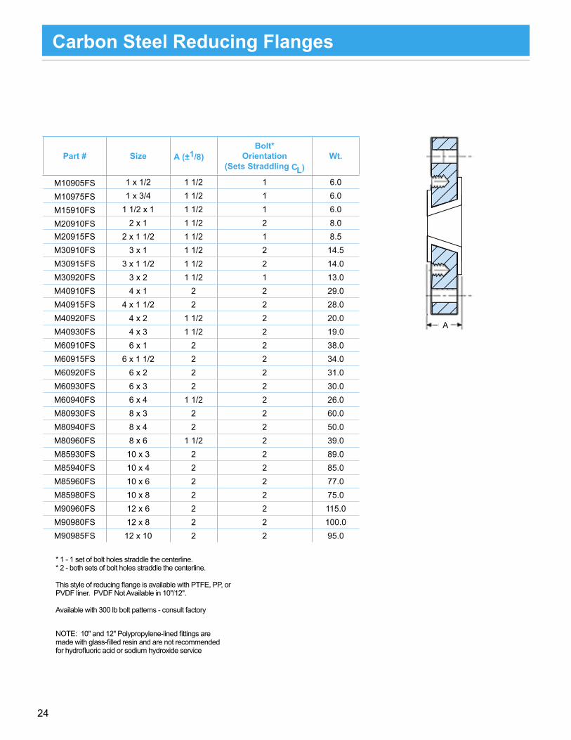
Part # Size A (±1/8)Bolt*
Orientation(Sets Straddling CL)
Wt.
M10905FS 1 x 1/2 1 1/2 1 6.0
M10975FS 1 x 3/4 1 1/2 1 6.0
M15910FS 1 1/2 x 1 1 1/2 1 6.0
M20910FS 2 x 1 1 1/2 2 8.0M20915FS 2 x 1 1/2 1 1/2 1 8.5M30910FS 3 x 1 1 1/2 2 14.5M30915FS 3 x 1 1/2 1 1/2 2 14.0M30920FS 3 x 2 1 1/2 1 13.0M40910FS 4 x 1 2 2 29.0M40915FS 4 x 1 1/2 2 2 28.0M40920FS 4 x 2 1 1/2 2 20.0M40930FS 4 x 3 1 1/2 2 19.0M60910FS 6 x 1 2 2 38.0M60915FS 6 x 1 1/2 2 2 34.0M60920FS 6 x 2 2 2 31.0M60930FS 6 x 3 2 2 30.0M60940FS 6 x 4 1 1/2 2 26.0M80930FS 8 x 3 2 2 60.0M80940FS 8 x 4 2 2 50.0M80960FS 8 x 6 1 1/2 2 39.0M85930FS 10 x 3 2 2 89.0M85940FS 10 x 4 2 2 85.0M85960FS 10 x 6 2 2 77.0M85980FS 10 x 8 2 2 75.0M90960FS 12 x 6 2 2 115.0M90980FS 12 x 8 2 2 100.0M90985FS 12 x 10 2 2 95.0
Carbon Steel Reducing Flanges 36
Carbon S
teel Reducing Filler Flanges
PTFE-LinedC
arbon Steel conforms to ASTM
A516 GR
70 or SAE 1010-1030.
1” – 8” is Full Vacuum rated to 450°F.
10” & 12” are not vacuum rated.
Note: The m
inor size bolt holes on reducing filler flanges are always
threaded. Also, many sizes of this style of reducing filler flange are con-
structed with both the m
ajor size and minor size bolt holes as threaded. This
is to prevent interference between bolt heads and nuts of the tw
o connectingflanges. Please be aw
are of what these w
ill be connected to - if connectingto other flanges that have threaded holes, a concentric reducer (through holes on both flanges) m
ay be required. The PTFE-lined ductile iron reducing flanges are constructed w
ith the major holes as through holes in all sizes. The thickness
dimension m
ay be different than the carbon steel reducing flange.
roja
Mez
iS
)S
PN(
roni
Mez
iS
)S
PN(
sreb
muNt
raP
k-ci
hTss
enD
O
selo
Htlo
B-H
selo
Htlo
B-E
eral
Fsr
ete
mai
Dtl
oB
elo
Hn
(degrees)oit
ato
R.o
Nez
iS
tlo
Bel
criC
.ai
D.o
Nez
iS
tlo
Bel
criC
.ai
Dht
peD
BA
GD
FK
J
15.
0710
0ZZ0
M00T
32/
11
4/1
44
31-2
/18/
13
431
-2/1
8/3
261
/11
1 3/82
1 11/1645
57.
0910
0ZZ0
M00T
34/
32
5.1
101
B00Z
Z0M0
0T3
2/1
15
431
-2/1
8/7
34
31-2
/18/
13
61/9
8/7
22
54
21
0120
0ZZ0
M00T
32/
11
64
11-8
/54/
34
431
-2/1
8/1
361
/98/
53
2en
oN
5.1
0B2
00ZZ
0M0
0T3
8/7
38/
58/
72
54
3
101
300Z
Z0M0
0T3
2/1
12/
17
411
-8/5
64
31-2
/18/
13
61/9
5
2en
oN
5.1
0B3
00ZZ
0M0
0T3
8/7
38/
58/
72
202
300Z
Z0M0
0T3
11-8
/54/
34
4/3
8/5
354
4
101
400Z
Z0M0
0T3
2
98
4/3
2/1
74
31-2
/18/
13
61/9
61/3
6
2
eno
N5.
10
B400
ZZ0
M00T
38/
73
8/5
8/7
2
202
400Z
Z0M0
0T3
2/1
111
-8/5
4/3
8/5
3
303
400Z
Z0M0
0T3
11-8
/56
5
6
1060
0ZZ
B0
600Z
Z 0M0
0T3
211
88/
72/
19
4
31-2
/18/
13
61/9
2/1
8
2
eno
N
51. 1
0M0
0T3
8/7
38/
58/
72
202
600Z
Z0M0
0T3
11-8
/5
4/3
4
4/3
8/5
3
303
600Z
Z0M0
0T3
65
404
600Z
Z0M0
0T3
2/1
101
-4/3
82/
17
61/3
6
8
303
800Z
Z0M0
0T3
22/
131
88/
74/
311
411
-8/5
64/
38/
501
5
eno
N4
0480
0ZZ0
M00T
38
2/1
761
/36
606
800Z
Z0M0
0T3
2/1
101
-4/3
01-4
/32/
19
61/3
12/
18
01
303
E00Z
Z0B0
0T3
261
211
4/1
41
4
01-4
/3
68/
5
4/3
21
5
eno
N4
04E0
0ZZ0
B00T
3
8
4/3
61/3
6
606
E00Z
Z0B0
0T3
2/1
961
/31
2/1
8
808
E00Z
Z0B0
0T3
9-8/
74/
311
8/5
01
21
606
F00Z
Z0B0
0T3
291
211
718
01-4
/32/
19
61/3
151
2/1
8
eno
N8
08F0
0ZZ0
B00T
34/
311
8/5
01
010
EF00
ZZ0
B00T
39-
8/7
219-
8/7
4/1
414/
11
4/3
21
150lb. Flanged
A
* 1 - 1 set of bolt holes straddle the centerline.* 2 - both sets of bolt holes straddle the centerline.
This style of reducing flange is available with PTFE, PP, or PVDF liner. PVDF Not Available in 10"/12".
Available with 300 lb bolt patterns - consult factory
NOTE: 10" and 12" Polypropylene-lined fittings are made with glass-filled resin and are not recommended for hydrofluoric acid or sodium hydroxide service

25
Carbon Steel Reducing Flanges, Non-Standard Sizes
Size A (±1/8)Bolt*
Orientation(Sets Straddling CL)
1 1/2 x 1/2 13/16 11 1/2 x 3/4 13/16 1
1 1/2 x 1 1/4 13/16 12 x 1/2 7/8 12 x 3/4 7/8 1
2 x 1 1/4 7/8 12 1/2 x 1 1 2
2 1/2 x 1 1/2 1 12 1/2 x 2 1 13 x 1 1/4 1 3/16 13 x 2 1/2 1 3/16 1
5 x 2 1 3/16 25 x 3 1 3/16 2
6 x 3/4 1 1/4 28 x 1 1 3/8 2
8 x 1 1/2 1 3/8 28 x 2 1 3/8 2
10 x 1 1 7/16 210 x 1 1/2 1 7/16 2
10 x 2 1 7/16 212 x 1 1 1/2 2
12 x 1 1/2 1 1/2 212 x 2 1 1/2 212 x 3 1 1/2 212 x 4 1 1/2 2
36
Carbon S
teel Reducing Filler Flanges
PTFE-LinedC
arbon Steel conforms to ASTM
A516 GR
70 or SAE 1010-1030.
1” – 8” is Full Vacuum rated to 450°F.
10” & 12” are not vacuum rated.
Note : The m
inor size bolt holes on reducing filler flanges are always
threaded. Also, many sizes of this style of reducing filler flange are con-
structed with both the m
ajor size and minor size bolt holes as threaded. This
is to prevent interference between bolt heads and nuts of the tw
o connectingflanges. Please be aw
are of what these w
ill be connected to - if connectingto other flanges that have threaded holes, a concentric reducer (through holes on both flanges) m
ay be required. The PTFE-lined ductile iron reducing flanges are constructed w
ith the major holes as through holes in all sizes. The thickness
dimension m
ay be different than the carbon steel reducing flange.
roja
Mez
iS
)S
PN(
roni
Mez
iS
)S
PN(
sreb
muNt
raP
k-ci
hTss
enD
O
selo
Htlo
B-H
selo
Htlo
B-E
eral
Fsr
ete
mai
Dtl
oB
elo
Hn
(degrees)oit
ato
R.o
Nez
iS
tlo
Bel
criC
.ai
D.o
Nez
iS
tlo
Bel
criC
.ai
Dht
peD
BA
GD
FK
J
15.
0710
0ZZ0
M00T
32/
11
4/1
44
31-2
/18/
13
431
-2/1
8/3
261
/11
1 3/82
1 11/1645
57.
0910
0ZZ0
M00T
34/
32
5.1
101
B00Z
Z0M0
0T3
2/1
15
431
-2/1
8/7
34
31-2
/18/
13
61/9
8/7
22
54
21
0120
0ZZ0
M00T
32/
11
64
11-8
/54/
34
431
-2/1
8/1
361
/98/
53
2en
oN
5.1
0B2
00ZZ
0M0
0T3
8/7
38/
58/
72
54
3
101
300Z
Z0M0
0T3
2/1
12/
17
411
-8/5
64
31-2
/18/
13
61/9
5
2en
oN
5.1
0B3
00ZZ
0M0
0T3
8/7
38/
58/
72
202
300Z
Z0M0
0T3
11-8
/54/
34
4/3
8/5
354
4
101
400Z
Z0M0
0T3
2
98
4/3
2/1
74
31-2
/18/
13
61/9
61/3
6
2
eno
N5.
10
B400
ZZ0
M00T
38/
73
8/5
8/7
2
202
400Z
Z0M0
0T3
2/1
111
-8/5
4/3
8/5
3
303
400Z
Z0M0
0T3
11-8
/56
5
6
1060
0ZZ
B0
600Z
Z 0M0
0T3
211
88/
72/
19
4
31-2
/18/
13
61/9
2/1
8
2
eno
N
51. 1
0M0
0T3
8/7
38/
58/
72
202
600Z
Z0M0
0T3
11-8
/5
4/3
4
4/3
8/5
3
303
600Z
Z0M0
0T3
65
404
600Z
Z0M0
0T3
2/1
101
-4/3
82/
17
61/3
6
8
303
800Z
Z0M0
0T3
22/
131
88/
74/
311
411
-8/5
64/
38/
501
5
eno
N4
0480
0ZZ0
M00T
38
2/1
761
/36
606
800Z
Z0M0
0T3
2/1
101
-4/3
01-4
/32/
19
61/3
12/
18
01
303
E00Z
Z0B0
0T3
261
211
4/1
41
4
01-4
/3
68/
5
4/3
21
5
eno
N4
04E0
0ZZ0
B00T
3
8
4/3
61/3
6
606
E00Z
Z0B0
0T3
2/1
961
/31
2/1
8
808
E00Z
Z0B0
0T3
9-8/
74/
311
8/5
01
21
606
F00Z
Z0B0
0T3
291
211
718
01-4
/32/
19
61/3
151
2/1
8
eno
N8
08F0
0ZZ0
B00T
34/
311
8/5
01
010
EF00
ZZ0
B00T
39-
8/7
219-
8/7
4/1
414/
11
4/3
21
150lb. Flanged
A
PTFE-Lined, Only
This style of reducing flange is available in sizes up to 30" diameter, and/or with 300 lb drill patterns, and/or with a non-taper straight-through bore.

26
Blind Flanges / Spectacle Blind Flanges
A
E
Bolt circle diam
eterC
Flange O.D.
Size A CBolt Holes, E
No. Size
1 4 1/4 9/16 4 5/81 1/2 5 11/16 4 5/8
2 6 3/4 4 3/43 7 1/2 15/16 4 3/44 9 15/16 8 3/46 11 1 8 7/88 13 1/2 1 1/8 8 7/8
10 16 1 3/16 12 112 19 1 1/4 12 1
BLIND FLANGES
H
DL
BA
Size A B D H L1 2 2 1/2 5/8 3/4 3 1/8
1.5 2 7/8 3 1/4 5/8 7/8 3 7/8
2 3 5/8 4 3/4 7/8 4 3/4
3 5 5 1/4 3/4 1 1/8 6
4 6 3/16 6 3/4 3/4 1 1/8 7 1/2
6 8 1/2 8 5/8 7/8 1 1/8 9 1/2
8 10 5/8 10 7/8 7/8 1 1/4 11 3/4
10 12 3/4 13 1/4 1 1 3/8 14 1/4
12 15 16 1 1 3/8 17
Size A B H L1 2 4 1/4 13/16 4 1/4
1.5 2 7/8 5 15/16 5
2 3 5/8 6 1 6
3 5 7 1/2 1 3/16 7 1/2
4 6 3/16 9 1 3/16 9
6 8 1/2 11 1 1/4 11
8 10 5/8 13 1/2 1 3/8 13 1/2
10 12 3/4 16 1 3/8 16
12 15 19 1 1/2 19
H
L
BA
ANSI 150Flange Bolt
Drilling
SPECTACLE BLIND FLANGES - RING STYLE
SPECTACLE BLIND FLANGES - FULL FACE STYLE

27
PTFE-Lined Sight Glass Indicators
Length
PTFE Liner
A
B
C
D
PTFE Liner
Size Length
1 71 1/2 8
2 93 114 136 16
DI SIGHT GLASS INDICATORS
Size A B C D
1 4.806 3.914 2.605 3 1/21 1/2 5.575 4.475 3.103 4
2 5.857 4.924 3.490 4 1/23 7.035 6.102 4.299 5 1/24 7.572 6.764 4.954 6 1/26 9.354 8.425 6.330 8
FABRICATED SIGHT GLASS INDICATORS

28
1 . Flange Dimensions: Bolt circle and flange bolt hole sizes per ANSI Class 150 dimensions.2. Materials: Body: Cast Ductile Iron (60-40-18) per ASTM A395. Liner Availability: PFA (1"-8"), PVDF (1"-4"), or PP (1"-8"). Ball: Solid PTFE (1"-8" Solid). Hardware: Studs per ASTM A193 Gr. B7, Nuts per SAE J995 Gr. 8. All hardware is zinc-p.3. Permanent name plates show sizes, liner material, and flow direction.4. Pressure Rating: Full-Vacuum to 150 psi.
5. Temperature Rating: PFA: -20° F to 450° F PVDF: -20° F to 275° F PP: -20° F to 225° F6. Flow (GPM) at pressure drop of 1 psi (water at 60° F).7. 8" Ball Check Valve consists of a 6" valve with two 8" x 6" reducing flanges. 8. Model 770 Ball Check Valve can be installed vertically or horizontally. See Model 770 Ball Check Valve Ball sealing force data sheet.
Model 770 Ball Check Valve
DIMENSIONS
1" 6" 5" 0.438" 2" 12 0.079 30 1.5" 7" 6.5" 0.563" 2.875" 22 0.268 75
2" 7" 7.25" 0.625" 3.625" 29 0.544 150
3" 8" 9" 0.75" 5" 49 1.759 250
4" 10.5" 11.5" 0.938" 6.125" 82 3.722 400
6" 15.5" 17.25" 1" 8.375" 190 18.69 550
8" 19.688" 17.25" 1.125" 10.5" 266 18.69 550
ValveSize A B C D
ValveWt., Lbs.
BallWt., Lbs. Flow
0 degree 45 degree 90 degree
Gallon/Minute Velocity in Feet/Second to Unseat DP Size 0° 45° 90° 0° 45° 90° 180° CV 1" 1.3 8.3 12.5 .6 3.6 6 .114 30
1.5" 5.9 23 30 .94 4.1 5.45 .159 75
2" 7 52 80 .76 5.5 8.69 .196 150
3" 16 71 105 .73 3.4 5 .273 250
4" 31 121 160 .86 3.5 4.47 .367 400
6–8" 60 170 210 .74 2.08 2.6 .520 550
Flow required to force ball into seat at various inclinations (Solid Ball)SEALING DATA
29
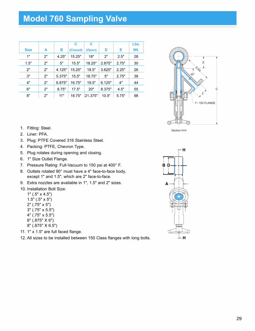
1. Fitting: Steel.2. Liner: PFA.3. Plug: PTFE Covered 316 Stainless Steel.4. Packing: PTFE, Chevron Type.5. Plug rotates during opening and closing.6. 1" Size Outlet Flange.7. Pressure Rating: Full-Vacuum to 150 psi at 400° F.8. Outlets rotated 90° must have a 4" face-to-face body, except 1" and 1.5", which are 2" face-to-face.9. Extra nozzles are available in 1", 1.5" and 2" sizes.10. Installation Bolt Size: 1" (.5" x 4.5") 1.5" (.5" x 5") 2" (.75" x 5") 3" (.75" x 5.5") 4" (.75" x 5.5") 6" (.875" X 6") 8" (.875" X 6.5")11. 1" x 1.5" are full faced flange.12. All sizes to be installed between 150 Class flanges with long bolts.
C C Lbs. Size A B (Closed) (Open) D E Wt.
1" 2" 4.25" 15.25" 18" 2" 2.5" 28
1.5" 2" 5" 15.5" 18.25" 2.875" 2.75" 30
2" 2" 4.125" 15.25" 18.5" 3.625" 2.25" 26
3" 2" 5.375" 15.5" 18.75" 5" 2.75" 38
4" 2" 6.875" 16.75" 19.5" 6.125" 4" 44
6" 2" 8.75" 17.5" 20" 8.375" 4.5" 55
8" 2" 11" 18.75" 21.375" 10.5" 5.75" 98
Model 760 Sampling Valve

30
113
Thermowell BafflesJacketed with PTFE
PTFE Jacketed Thermowell-baffles for inserting thermocouples below the liquid level of corrosion mixtures are designed towithstand immersion in all acids, except hydrofluoric, at temperatures to 350°F. Their corrosion resistance and strength are alsodesigned to provide long-life and maintenance-free operation of both thermowells and vessels. They are constructed of a PTFEjacketed steel pipe with a special tantalum bulb swaged on the bottom end. Heat conductivity of 0.130 cal./cm2/°C/sec. isprovided through the tantalum bulb, which combines good chemical resistance with high thermal conductivity.
*Thermowells have oversize O.D., which will not fit directly into standard size vessel nozzles. By selecting asmaller size pipe and a R60692 Special Reducing Flange, the correct fit can be achieved.**Recommended maximum length for mild agitation is shown as a general guide for liquids having about thesame density and viscosity as water. For longer lengths or more severe operating loads (density, viscosity andvelocity of fluid at the pipe), a larger size or internal bracing should be employed. Exceeding the maximumrecommended service temperature and/or pressure or maximum recommended unsupported length can result inpremature failure and possible personnel and equipment hazard.
Notes: Maximum Length = 10 ft.
ataDlanoisnemiD
#traP SPN egnalFeziS
laeSteksaG.aiD A lanimoN
*.D.O
dednemmoceR.xaM**htgneLdetroppusnU
.tF
L-80-A28291R 2/1 1 8/71 61/11 1 3
L-61-A28291R 1 2/11 4/32 61/31 23/511 4
L-42-A28291R 2/11 2 2/13 8/7 61/12 5
L-23-A28291R 2 3 8/34 61/11 61/92 6
Dimensional Data Flange Gasket Nominal Part # NPS Size Seal Dia. A O.D. Consult Factory 1/ 2 1 13/4 11/16 1 3
Consult Factory 1 11/ 2 2 3/4 13/ 16 115/ 32 4
Consult Factory 11/2 2 31/2 7/8 2 1/ 16 5
Consult Factory 2 3 5 11/16 2 9/ 16 6
Max. UnsupportedLength, Ft.
THERMOWELL BAFFLE
Recommended maximum length for mild agitation is shown as a general guide for liquids having about thesame density and viscosity as water. For longer lengths or more severe operating loads (density, viscosity andvelocity of fluid at the pipe), a larger size or internal bracing should be employed. Exceeding the maximumrecommended service temperature and/or pressure or maximum recommended unsupported length can result inpremature failure and possible personnel and equipment hazard.
Notes: Maximum Length = 10 ft.
Thermowell Baffles

31
114
Dip PipesLined and Jacketed with PTFE for Loading, Unloading & Decanting
Resistoflex Dip Pipes are designed to provide the ultimate in corrosion-resistant, non-contaminating construction to 350°F forloading vessels below the liquid level, and decanting and unloading without the need for bottom outlets. The maximum recom-mended operating pressure is 150 psi.
They are designed to withstand high mechanical loads imposed by mixing or agitation in process vessels and reactors. Theschedule 80 steel pipe (also available is SS, Alloy 20, Hastelloy, etc.) is protected from corrosion by an extruded, high density,chemically inert PTFE liner and jacket which are fused together at the bottom. Both the liner and the jacket are applied in amanner, which compensates for thermal expansion, using the Resistoflex Thermalok process.
Warning: Exceeding the maximum recommended service temperature and/or pressure, or recommended unsupported lengthcan result in premature failure and personnel and/or equipment hazard.
4" - 20" dip pipes are available (manufactured by Resistoflex GmbH). Contact us for more information.
*Use Reducing Flanges (seen on Page 63) to adapt for larger nozzles.**Recommended maximum length for mild agitation is shown as a general guide for liquids having about the same density andviscosity as water. For longer lengths, or more severe operating loads (density, viscosity and velocity of fluid at the pipe), alarger size of internal bracing should be employed.
Note: The nozzle flange sizes shown are the only sizes available. To connect a dip pipe to a larger nozzle, areducing flange must be used. Contact factory for more information as not all standard reducing flanges are suitable.
Solid PTFE dip pipes and spargers are also available.
ataDlanoisnemiD
#traP&epiP
gnitcennoCeziSegnalF
elzzoNeziSegnalF
foretemaiD.niMteksaGtekcaJ
laeS
foretemaiDteksaGreniL
laeS
lanimoN*.D.O
dednemmoceR.xaM**htgneL
.tF
L-61-8086R 2/1 1 8/71 8/31 1 3
L-42-6186R 1 2/11 4/32 2 61/71 4
L-23-4286R 2/11 2 2/13 8/72 46/12 5
L-84-2386R 2 3 8/34 8/53 2/12 6
L-46-8486R 3 4 61/75 5 8/53 8
Reinforced Dip Pipes and Spargers
SizePipe and
Connecting Flange Size
Nozzle Flange
Size
Min. Diameter of Jacket Gasket
Seal
Diameter of Liner Gasket
Seal
Nominal OD
Max. Recommended Unsupported Length
(Ft.)1/2 1/2 1 1 7/8 1 3/8 1 31 1 1 1/2 2 3/4 2 1 7/16 4
1 1/2 1 1/2 2 3 1/2 2 7/8 2 1/64 52 2 3 4 3/8 3 5/8 2 1/2 63 3 4 5 7/16 5 3 5/8 8
REINFORCED DIP PIPE
Pipe and Connecting Flange Size
Nozzle Flange
Size
Min. Diameter of Jacket Gasket
Seal
Nominal OD
Max. Recommended Length
1 2 1 7/8 1 15/16 41 1/2 3 2 3/4 2 9/16 51 1/2 4 3 1/2 2 33/64 5
2 4 4 3/8 3 63 6 5 7/16 4 1/8 8
REINFORCED SPARGER
SpargersLined and Jacketed with PTFE for Injecting Steam & Other Vapors.
Resistoflex Spargers for injecting steam and other vapors below the liquid level are designed to be highly resistant to mechani-cal fatigue and thermal shock, and provide the ultimate in corrosion-resistant, non-contaminating construction to 350°F.
Resistoflex Spargers used schedule 80 pipe, lined and jacketed with PTFE and are designed to withstand the high mechanicalloads associated with mixing or agitation in reactors or other process vessels. An external heavy wall PTFE tube is then appliedwhich extends beyond the weld of the lined and jacketed steel reinforcement to provide a sparging section at the bottom. A PTFEplug, held by PTFE bolts and nuts, is installed at the end of this heavy tube and minimizes corrosion deposits and its nonsticksurface retards buildup of precipitated solids at the orfices. Good erosion resistance maintains contamination free service. Thepacking gland provides gas-tight seals up to 50 psi.
Warning: Exceeding the maximum recommended service temperature and/or pressure, or recommended unsupported lengthcan result in premature failure and personnel and/or equipment hazard.
Note: The nozzle flange sizes shown are the only sizes available. To connect a sparger to a largernozzle, a reducing flange must be used. Contact factory for more information as not all standardreducing flanges are suitable.
ataDlanoisnemiD
#traP&epiP
gnitcennoCeziSegnalF
elzzoNeziSegnalF
lanimoN*.D.O
dednemmoceR.xaM**htgneLdetroppusnU
.tF
XX-L-236176R 1 2 61/511 4
XX-L-844286R 2/11 3 61/92 5
XX-L-464276R 2/11 4 46/332 5
XX-L-462376R 2 4 3 6
XX-L-698476R 3 6 8/14 8
Note: Nozzle flange sizes on reinforced dip pipes and spargers are limited to those shown. To connect to other size nozzles, special ID reducing flanges (see following page) can be installed between the dip pipe / sparger and the vessel nozzle.
Single flange dip pipes are also available. Nozzle flange is always one size larger than the dip pipe size. The flare diameter is standard for the nominal dip pipe size, not the nozzle flange size.

32
SizeActual
Smallest ID
A
1 x 1/2 13/32 1 5/81 x 3/4 5/8 1 5/8
1 1/2 x 1 1 1/8 1 9/162 x 1 1 1/8 1 9/16
2 x 1 1/2 1 5/8 1 9/162 1/2 x 2 2 1/8 1 9/16
3 x 1 1 1/8 1 5/83 x 1 1/2 1 5/8 1 5/8
3 x 2 2 1/8 1 3/43 x 2 1/2 2 3/16 1 5/8
4 x 1 1 1/8 1 7/84 x 1 1/2 1 5/8 1 5/8
4 x 2 2 1/8 24 x 3 2 25/32 1 3/45 x 4 3 3/4 1 5/8
6 x 1 1/2 1 5/8 1 7/86 x 2 2 1/8 1 7/86 x 3 2 31/32 1 3/46 x 4 3 3/4 2 1/86 x 5 4 25/32 1 3/48 x 4 3 29/32 28 x 6 5 25/32 2
10 x 4 4 1/16 2 7/1610 x 6 5 29/32 2 7/1610 x 8 7 11/16 2 7/16
(Bored)
(Drilled and tapped)
A
(Bored)
(Drilled and tapped)
A
Special ID Reducing Flanges for Dip Pipes
These reducing flanges are PTFE-Lined, only

33
a (inches)taDlanoisnemiD
eziSgnibuT gulP&egnalFssenkcihT
dneBsuidaR
R
gnilpuoC.D.O
X.D.O .D.I
4/11 2/1 1 2 8/12
8/31 4/3 1 2 4/12
4/31 1 2/11 3 8/52
4/12 2/11 2 4 8/33
3 2 2/12 8 8/34
PTFEThreaded
PinA
OD ID
PTFETubing A
OptionalBack-Up Flange
PTFEThreaded
Pin
PTFEThreaded
Plug
Sparger is Shown. Dip pipes are open-ended
Sparger is Shown. Dip pipes are open-ended
Tubing Size PTFE Flange and Plug
Thickness, A
PTFE Flange O.D., B
Bend Radius, R
Coupling OD, XO.D. I.D.
1 1/4 1/2 1
Specified by Customer
2 2 1/81 3/8 3/4 1 2 2 1/41 3/4 1 1 1/2 3 2 5/82 1/4 1 1/2 2 4 3 3/8
3 2 2 1/2 8 4 3/8
Solid PTFE Dip Pipes and Spargers
R6
Part Number Code:
X X X X X - L - V - C
PTFE
Style
0 = Straight1 = 1 bend 90o
2 = 1 bend 45o
6 = 2 bends 30o
7 = 2 bends 45o
8 = 2 bends 90o
5 = Dip Pipe1 = Sparger
Shape
Tubing Size
PTFE Flange Dia. "B"
Back-up Flange
0 = None1 = Back-up Flange2 = PTFE Flange to be removable
1 = 1 1/4" OD x 1/2" ID2 = 1 3/8" OD x 3/4" ID3 = 1 3/4" OD x 1" ID4 = 2 1/4" OD x 1 1/2" ID5 = 3" OD x 2" ID
1 = 2" (when connecting to a 1" Flange)2 = 2 7/8" (when connecting to a 1.5" Flange)3 = 3 5/8" (when connecting to a 2" Flange)4 = 5" (when connecting to a 3" Flange)5 = 6 3/16" (when connecting to a 4" Flange)(Other diameters available on request)
Length Callout
B
L, V, and Z dimensions are specified by the customer.

34
PTFE Mixing Tee Nozzles
Acid mixing tees are used to introduce acid to the system. The solid PTFE nozzle is speciallydesigned to disperse the acid uniformly into the process. Various nozzle sizes are available fordifferent outlet diameters. Optional open-ended constructions are also available. The tees aremade in 1" through 8" sizes for standard and reducing tees, and are available on special request.The PTFE mixing nozzle is also used with plastic lined tees. When selecting a tee, be sure theheat of reaction does not exceed the temperature rating of the plastic liner.
Note: Mixing tee nozzles purchased separately may not always fit in an existing tee, depending on size and construction. Mixing tees and nozzles should be purchased together toenable a factory fit.
Detail 1 Detail 2 Detail 3 Detail 4
seeTgnicudeRroF
eziSSizeCode A B C .D.I
B1 1
1
2
1
2
2
2
2
3
2
3
4
1
2
2
4
6
1
22
2
2
1
1
x2/11 4 8/52 61/9 4/1
21 x2 2/14 8/52 61/9 4/1
2B /11x2 2/14 8/33 8/11 2/1
31 x3 2/15 8/52 61/9 4/1
3B /11x3 2/15 8/33 8/11 2/1
32 x3 2/15 8/14 8/31 8/7
4B /11x4 8/37 8/33 8/11 2/1
42 x4 8/37 8/14 8/31 8/7
43 x4 8/37 8/35 2/12 2/11
62 x6 8/39 8/14 8/31 8/7
63 x6 8/39 8/35 2/12 2/11
64 x6 8/39 8/76 2/12 2/11
81 x8 11 8/52 61/9 4/1
8B /11x8 11 8/32 8/11 2/1
82 x8 11 8/14 8/31 8/7
84 x8 11 8/76 2/12 2/11
86 x8 11 4/38 2/12 2/11
41 x4 8/37 8/52 61/9 4/1
6B /11x6 8/39 8/33 8/11 2/1
C1 x2/12 5 8/52 61/9 4/1
CB /11x2/12 5 8/33 8/11 2/1
C2 x2/12 5 8/14 8/31 8/7
61 x6 8/39 8/52 61/9 4/1
seeTdradnatSroF
eziS A B C .D.I
/13 8/52 61/9 4/1
/11 4 8/33 5/11 2/1
/14 8/14 8/31 8/7
/15 8/35 2/12 2/11
/37 8/76 2/12 2/11
/39 4/38 2/12 2/11
1 11 2/12 2/11
10 1 2
2
2
8
8
11
23
46
8
2
2B02030
40
6080C0 /12 5 8/74 4/31 1
SizeCode
WM0WM00000_ _0 WM0XM00000_ _0 WM0YM00000_ _0 WM0ZM00000_ _0Part No.:
Size Code
35
Acid mixing tees are used to introduce acid to the system. The solid PTFE nozzle is speciallydesigned to disperse the acid uniformly into the process. Various nozzle sizes are available fordifferent outlet diameters. Optional open-ended constructions are also available. The tees aremade in 1" through 8" sizes for standard and reducing tees, and are available on special request.The PTFE mixing nozzle is also used with plastic lined tees. When selecting a tee, be sure theheat of reaction does not exceed the temperature rating of the plastic liner.
Note: Mixing tee nozzles purchased separately may not always fit in an existing tee, depending on size and construction. Mixing tees and nozzles should be purchased together toenable a factory fit.
Detail 1 Detail 2 Detail 3 Detail 4
seeTgnicudeRroF
eziSSizeCode A B C .D.I
B1 1
1
2
1
2
2
2
2
3
2
3
4
1
2
2
4
6
1
22
2
2
1
1
x2/11 4 8/52 61/9 4/1
21 x2 2/14 8/52 61/9 4/1
2B /11x2 2/14 8/33 8/11 2/1
31 x3 2/15 8/52 61/9 4/1
3B /11x3 2/15 8/33 8/11 2/1
32 x3 2/15 8/14 8/31 8/7
4B /11x4 8/37 8/33 8/11 2/1
42 x4 8/37 8/14 8/31 8/7
43 x4 8/37 8/35 2/12 2/11
62 x6 8/39 8/14 8/31 8/7
63 x6 8/39 8/35 2/12 2/11
64 x6 8/39 8/76 2/12 2/11
81 x8 11 8/52 61/9 4/1
8B /11x8 11 8/32 8/11 2/1
82 x8 11 8/14 8/31 8/7
84 x8 11 8/76 2/12 2/11
86 x8 11 4/38 2/12 2/11
41 x4 8/37 8/52 61/9 4/1
6B /11x6 8/39 8/33 8/11 2/1
C1 x2/12 5 8/52 61/9 4/1
CB /11x2/12 5 8/33 8/11 2/1
C2 x2/12 5 8/14 8/31 8/7
61 x6 8/39 8/52 61/9 4/1
seeTdradnatSroF
eziS A B C .D.I
/13 8/52 61/9 4/1
/11 4 8/33 5/11 2/1
/14 8/14 8/31 8/7
/15 8/35 2/12 2/11
/37 8/76 2/12 2/11
/39 4/38 2/12 2/11
1 11 2/12 2/11
10 1 2
2
2
8
8
11
23
46
8
2
2B02030
40
6080C0 /12 5 8/74 4/31 1
SizeCode
WM0WM00000_ _0 WM0XM00000_ _0 WM0YM00000_ _0 WM0ZM00000_ _0Part No.:
Size Code
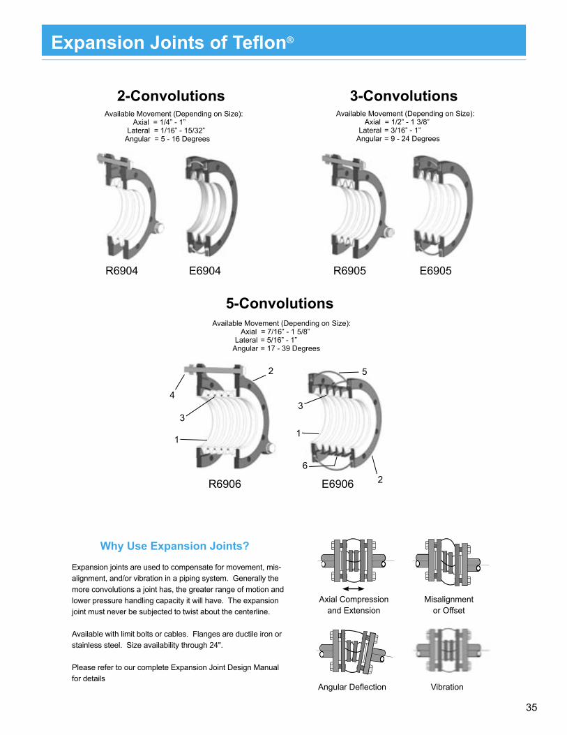
Expansion Joints of Tefl on®
2-Convolutions
Expansion joints are used to compensate for movement, mis-alignment, and/or vibration in a piping system. Generally the more convolutions a joint has, the greater range of motion and lower pressure handling capacity it will have. The expansion joint must never be subjected to twist about the centerline.
Available with limit bolts or cables. Flanges are ductile iron or stainless steel. Size availability through 24".
Please refer to our complete Expansion Joint Design Manual for details
Why Use Expansion Joints?
Angular Defl ection
Misalignment or Offset
Axial Compression and Extension
Vibration
R6905 E6905
Available Movement (Depending on Size): Axial = 1/2” - 1 3/8” Lateral = 3/16” - 1” Angular = 9 - 24 Degrees
Available Movement (Depending on Size): Axial = 7/16” - 1 5/8” Lateral = 5/16” - 1” Angular = 17 - 39 Degrees
R6906
1
2
3
4
E6906
1
3
2
5
6
R6904 E6904
Available Movement (Depending on Size): Axial = 1/4” - 1” Lateral = 1/16” - 15/32” Angular = 5 - 16 Degrees
3-Convolutions
5-Convolutions
36
When assembling flange connections, always use a fullcomplement of clean, new high strength A193-B7 bolting. Ifusing stainless steel bolting, the bolts should be A193 Gr .B8M Class 2A and nuts should be A193 Gr . B8M Class 2B. Ifother bolting materials are used, the end user must ensurethat the new bolting material strength properties exceed thecalculated bolt stress values to be generated in making thepiping connection.
1) Always use flat washers on both sides of the connection.
2) Tighten the flange bolts with a calibrated torque wrench. The recommended bolt torque values are shown in the tables on the reverse of this card. Note: For zinc-plated bolts, or with anti-seize compounds, the torque values will be different. Please contact PSI for more informat- ion.
3) Tighten the flange bolts with a torque wrench, using a “crisscross” pattern that alternately tightens the bolts located 180 degrees apart.
4) Using this pattern, tighten the bolts in 20% increments of the final bolt torque until 80% of final bolt torque has been achieved.
5) For tightening to the final torque values, tighten bolts seq- uentially clockwise once around the flange. This will help ensure that the bolts are evenly stressed.
6) Care should be taken to avoid over-torquing, which can cause damage to the plastic sealing surfaces.
NOTE: When bolting together dissimilar materials, alwaystighten to the lowest recommended torque of the componentsin the joint. Using higher torques may cause excessivedeformation of the “softer” material in the joint. Install a 1/2"thick spacer between PS I plastic-lined pipe or fittingsand other plastic-lined components, particularly valves, if thediameters of the raised plastic faces are different. Bellevillewashers are not recommended for use with PTFE-linedproducts.
Retorquing
A retorque should be applied a minimum of 24 hours after theinitial torque or after the first thermal cycle. This allows forseating of the plastic and for relaxation of the bolts. If thesystem is to perform at elevated temperatures, it is recom-mended that hot water be circulated at the maximum operat-ing temperature of the process (if possible) for a minimum of24 hours. This allows for the pipe system to experience onethermal cycle. After cool-down, retorquing of the system
Hydrotesting
plastic face.
should be done. Torquing should only be done on the systemin the ambient, cooled state, never while the process is atelevated temperature, or excessive force could be applied tothe plastic faces. Never disassemble a flange joint in a hotsystem. Wait until the system has booled to ambient tem-perature.
Normally, after initial torque and retorque, a hydrotest shouldbe performed following ANSI requirements. Experience hasshown that if the above procedure has been followed very few,if any, of the flange joints may fail the hydrotest. If a flange jointdoes leak, first check the torque values, then tighten in 10%increments over the specified bolt torques until sealed.However, if 150% of the specified torque value is reached andthe flange joint still leaks, stop and disassemble the flangejoint. Something else is probably wrong such as a scratched
Only after the hydrotest has been successfully completed andany leaks corrected, can the pipeline be signed off andcommissioned.
Annual retorquing
Retorquing should be done at least annually thereafterespecially if the process line experiences elevated tempera-tures or extreme ambient temperature situations. Torquingshould only be done on the system in the ambient, cooledstate, never while the process is at elevated temperature orexcessive force could be applied to the plastic faces.
Retorquing (continued)
Flange Bolt Torquing

37
Pressure Testing
Pipe and fittings manufactured by PSI can be tested atthe pressures recommended by ASME B31.3.
Hydrostatic Test
The fluid used for the hydrostatic test is typically water. Anothersuitable non-toxic liquid can be substituted if there is the riskof damage due to the adverse effects of having water in thesystem. The system should be tested at a pressure not lessthan 1.5 times the design pressure. If the design temperatureis above the test temperature then the required test pressureis calculated by the following equation:
Pt = (1.5 PSt) S
WherePt = minimum hydrostatic test gauge pressureP = internal design gauge pressureSt = stress value at test temperatureS = stress value at design temperature
Typically, for the pressures and temperatures in which plastic-lined pipe is used, the above calculation reduces to:
Pt = 1.5 P
We recommend that the system be retorqued after the firstthermocycle. If the hydrostatic test is performed at the ex-pected operating temperature (a “hot hydrotest”) then thehydrotest can constitute the first thermocycle and the recom-mended retorquing can occur after the pressure test.
Pneumatic Leak Test
This pressure test is performed in some situations where thepresence of any water in the system is forbidden. The test isvery dangerous due to the stored energy of the compressedgas. ASME B31.3 refers to the dangers of performing this testand provides safety considerations in the standard.
For a pneumatic pressure test, a pressure relief device mustbe in the system. This relief device should be set at the testpressure plus either 50 psi or 10% of the test pressure,whichever is lower. The gas used for the pneumatic test, if not
air, can be any nonflammable and non-toxic gas. The testpressure required for this test is 110% of the design pressure.
To perform the pneumatic leak test, begin by increasing thepressure until a gauge pressure of 25 psi is attained. At thispoint, a preliminary check for leaks must be made. After theinitial check, the pressure should be incrementally increased,holding the pressure at each increment long enough toequalize the piping strains. Once the test pressure is reached,the pressure is then reduced to the design pressure beforeexamining for leakage.
Alternative Leak Test
If a hydrostatic pressure test is undesirable due to the possiblechemical reactions with water and a pneumatic test in undesir-able due to the potential hazards, then an alternative leak testcan be used. This test is not applicable to plastic lined pipebecause it relates to welded systems.
Initial Service Leak Test
This test is applicable only to systems, which meet the follow-ing requirements:
• The fluid handled is nonflammable, non-toxic,and not damaging to human tissues.
• The design gauge pressure does not exceed 150 psi.• The design temperature is between -20°F and 366°F.
In this test, the test fluid is the service fluid. It is rare that thistest is used with plastic-lined pipe. ASME B31.3 should beconsidered if more information concerning this test is required.
Other Tests
Another option, which is not included in ASME B31.3, is the“halogen test with Freon”. This test will find leaks in the pipingsystem, but it does not meet the code.
The above is a description of some pressure test methods. Ingeneral, most systems are hydrostatically tested as describedin the ASME standard. If the hydrostatic test is impractical, thenthe pneumatic test can be substituted, however, extremecaution must be observed during this potentially hazardoustest.
Flange Bolt Torquing

38
smetsyS051ssalCISNAstunH2491Adnastlob7B391AdelioylthgiL
epiPeziS
)bl-tf(euqroTtloB
PP FDVP EFTP
.niM .xaM .niM .xaM .niM .xaM
1 31 71 71 12 8 31
5.1 13 14 14 05 91 13
2 56 58 58 401 93 56
3 301 431 431 561 26 301
4 76 88 88 801 04 76
6 421 161 161 991 57 421
8 761 712 712 762 001 761
01 751 402 --- --- 49 751
21 391 152 --- --- 611 391
smetsyS003ssalCISNAstunH2491Adnastlob7B391AdelioylthgiL
epiPeziS
)bl-tf(euqroTtloB
PP FDVP EFTP
.niM .xaM .niM .xaM .niM .xaM
1 71 22 22 72 01 71
5.1 74 16 16 57 82 74
2 33 24 24 25 02 33
3 26 08 08 99 73 26
4 18 501 501 031 94 18
6 38 801 801 231 05 38
8 031 961 961 702 87 031
01 531 571 --- --- 18 531
21 681 242 --- --- 211 681
1
24
3
1
2
4
3 5
6
7
8
Note: For PSI components rotationally-lined with Tefzel® ETFE, use the same torque values as for PVDF.
Note: For specialty items rotationally-lined with Tefzel® ETFE, use values for PVDF.
Bolt Torque Requirements

39
smetsyS051ssalCISNAstunH2491Adnastlob7B391AdetaocEFTP
epiPeziS
)bl-tf(euqroTtloB
PP FDVP EFTP
.niM .xaM .niM .xaM .niM .xaM
1 8 01 01 31 5 8
5.1 91 52 52 03 11 91
2 93 15 15 26 32 93
3 26 08 08 99 73 26
4 04 35 35 56 42 04
6 57 79 79 911 54 57
8 001 031 031 061 06 001
01 49 321 --- --- 75 49
21 611 051 --- --- 96 611
smetsyS003ssalCISNAstunH2491Adnastlob7B391AdetaocEFTP
epiPeziS
)bl-tf(euqroTtloB
PP FDVP EFTP
.niM .xaM .niM .xaM .niM .xaM
1 01 31 31 61 6 01
5.1 82 73 73 54 71 82
2 02 52 52 13 21 02
3 73 84 84 95 22 73
4 94 36 36 87 92 94
6 05 56 56 97 03 05
8 87 101 101 421 74 87
01 18 501 --- --- 94 18
21 211 541 --- --- 76 211
smetsyS051ssalCISNAstunH2491Adnastlob7B391AdetalPcniZ
epiPeziS
)bl-tf(euqroTtloB
PP FDVP EFTP
.niM .xaM .niM .xaM .niM .xaM
1 91 52 52 13 21 91
5.1 64 95 95 37 72 64
2 49 321 321 151 75 49
3 941 491 491 932 09 941
4 89 721 721 751 95 89
6 081 432 432 882 801 081
8 242 413 413 783 541 242
01 822 692 --- --- 731 822
21 082 463 --- --- 861 082
Bolt Torque RequirementsBolt Torque Requirements
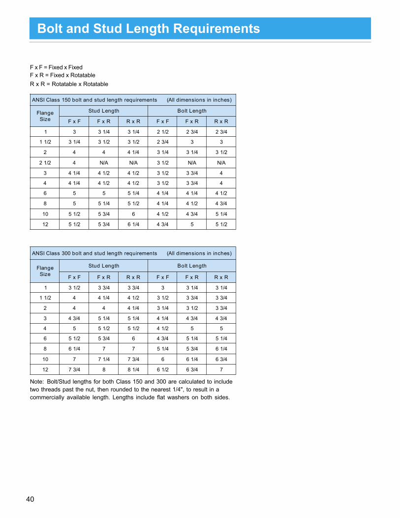
40
Bolt & Stud Length Requirementsfor Resistoflex Plastic-Lined Pipe and FittingsF x F = Fixed x FixedF x R = Fixed x RotatableR x R = Rotatable x Rotatable
Note: Bolt/Stud lengths for both Class 150 and 300 are calculated to includetwo threads past the nut, then rounded to the nearest 1/4", to result in acommercially available length. Lengths include flat washers on both sides.
)sehcninisnoisnemidllA(stnemeriuqerhtgneldutsdnatlob051ssalCISNA
egnalFeziS
htgneLdutS htgneLtloB
FxF RxF RxR FxF RxF RxR
1 3 4/13 4/13 2/12 4/32 4/32
2/11 4/13 2/13 2/13 4/32 3 3
2 4 4 4/14 4/13 4/13 2/13
2/12 4 A/N A/N 2/13 A/N A/N
3 4/14 2/14 2/14 2/13 4/33 4
4 4/14 2/14 2/14 2/13 4/33 4
6 5 5 4/15 4/14 4/14 2/14
8 5 4/15 2/15 4/14 2/14 4/34
01 2/15 4/35 6 2/14 4/34 4/15
21 2/15 4/35 4/16 4/34 5 2/15
)sehcninisnoisnemidllA(stnemeriuqerhtgneldutsdnatlob003ssalCISNA
egnalFeziS
htgneLdutS htgneLtloB
FxF RxF RxR FxF RxF RxR
1 2/13 4/33 4/33 3 4/13 4/13
2/11 4 4/14 2/14 2/13 4/33 4/33
2 4 4 4/14 4/13 2/13 4/33
3 4/34 4/15 4/15 4/14 4/34 4/34
4 5 2/15 2/15 2/14 5 5
6 2/15 4/35 6 4/34 4/15 4/15
8 4/16 7 7 4/15 4/35 4/16
01 7 4/17 4/37 6 4/16 4/36
21 4/37 8 4/18 2/16 4/36 7
Bolt and Stud Length Requirements

41
Storage and MaintenanceHandling and storing plastic-lined pipe
To obtain maximum performance from plastic-lined piping products, it is important that the flared or molded end faces of theplastic are protected from damage during storage, handling and installation. The following should be considered when han-dling Plastic-Lined Piping Products.
• Store indoors or under cover.• Products are shipped with a high performance, two component, epoxy primer protective coating. This coating in only a
primer and is not meant for outdoor exposure without a suitable topcoat. Protective end caps are not designed forprolonged outdoor exposure.
• The protective end caps on all pipe and fittings should be left in place until the pipe is ready to be installed. Do notdamage the plastic sealing faces when removing the end caps.
• Avoid rough handling of plastic-lined pipe in temperatures below 40°F. Plastic becomes brittle in low temperatures,and is more susceptible to cracking during rough handling.
• Never put the lifts of a forklift inside of the pipe to transport. This can damage the plastic liner.• The following temperature guidelines should be followed for plastic-lined piping products:
Do not store plastic-lined pipe in temperatures below 0°F. Avoid storing plastic-lined piping productswhere they will be exposed to ultraviolet light for long periods of time.
• The center of gravity of bent lined pipe may not be readily apparent. Be sure to handle carefully.
Safety precautions for plastic-lined pipe
Plastic-lined pipe can be fabricated on-site by properly certified personnel. When field fabricating, adequate ventilation (such asexhaust fans) should be used. Overheating of the plastic can cause it to degrade and generate vapors.
Avoid breathing vapors. Vapors can cause severe irritation to skin, eyes, and respiratory tract. When field fabricating, never heat the plastic with a torch or open flame.
Painting Plastic-Lined Piping Products
All pipe, fittings, and valves supplied by PSI have a gray protective coating applied to minimize oxidation during ship pingand handling. Refer to NACE guidelines and recommendations for sandblasting and selection of an appropriate primer andtopcoat suitable for your plant environmental conditions.
It is important that the raised plastic face on all plastic-lined piping components is protected from damage during sandblastingand painting. Make sure that the protective end caps remain in place at all times during these operations, and direct thesandblasting away from the face of the flange. As an extra precaution, you may want to remove the protective end cap, applyprotective tape over the plastic face, and then replace the cap before sandblasting and painting. If the exterior of the pipe is to betreated with a head curable protective coating, exercise caution during the heating process. Never apply heat in excess of theliner’s maximum temperature rating.
Vent holes on PTFE-lined pipe and PTFE-lined fittings should not be plugged with paint. The collars and holes are part of the venting system needed to prevent possible gas buildup behind the liner and possible liner collapse. Pipe, fittings and valvescan be special ordered without paint, but longer lead times are necessary.
*LINED PIPE AND FITTINGS TO BE STORED UNDER COVER UNTIL THE TIME OF INSTALLATION.
Storage and Maintenance

42
Per 100 Feet of Straight PSI Plastic-Lined Pipe
INSTRUCTIONS FOR USE
1) You must know the flowrate in gallons per minute (gpm),or the velocity in feet per second (fps).
2) If you know the velocity in fps, go directly to the charts andlocate the pressure drop for the velocity and line size youare working with.
3) If you don’t know the velocity, but know the flowrate in gpm,follow the example below to determine velocity in fps:
SizeCF1” .69331.5” .24332” .13223” .05434” .03006” .01328” .007310” .004512” .0031
Note: CF factors were determined using the average ID’s ofPSI lined pipe for PTFE, PP, and PVDF liners.
Example:
What is the pressure drop in 2” pipe at 60 gpm? First multiply60 gpm x .1322 (CF factor for 2” pipe) to get a velocity of 7.93feet per second. Look up the pressure drop for that velocityand line size in the charts. The pressure drop is approx.4.5 psi per 100 ft. of straight pipe.
If the resultant pressure drop is too high for your needs, repeatthe procedure for the next higher line size, until you get apressure drop that is suitable. Conversely, a smaller line sizewill result in higher pressure drop for a given flowrate.
Pressure drops were determined using the Darcy equation.Average lined pipe I.D.’s were used together with frictionfactors obtained from the Moody Diagram. Per a study madeby Battelle Institute, the friction factors were derived using relative roughness factors for perfectly smooth pipes.
.
FITTINGS
For pressure drops in fittings, please refer to a Piping Hand-book giving that information for unlined components inequivalent feet of pipe. Then use the pressure drop chart forPTFE lined pipe.
PTFE Lined Pipe Pressure Drop Water at 60°F
PRESSURE DROP (PSI)
VELOCITY (FT./SEC.)
PRESSURE DROP (PSI)
VELOCITY (FT./SEC.)
Note: The information on this page is intended to give a general ideaof pressure drop for plastic-lined pipe. For actual pressure dropcalculations used to size pumps or piping, use published formulasfrom recognized sources, such as Crane Technical Paper 410,which is also available as software.
Pressure Drop Information

43
Heat Tracing
Many products freeze or become viscous when exposed to ambient temperatures. Other polymerize, react, or become corrosivewhen exposed to ambient temperatures (e.g., condensation of a permeating vapor through a PTFE liner). Successful storageand transfer of such products, in most cases, requires that the piping and associated equipment be heat traced. Throughout theindustry, steam, fluid, and electric heat tracing systems are widely used. All are intended for the same purpose of pipe heating,but each has its own design considerations and limitations.
The potential problem with heat tracing plastic lined pipe is overheating of the plastic liner. In PTFE lined pipe, localized heatingcan cause increased permeation, resulting in a single lobe collapse of the liner. Each liner has a maximum service tempera-ture; however, some aggressive chemicals can reduce the temperature limits of the plastic. The following outlines the maxi-mum service temperatures for the liners, recommended heat tracing methods for each liner, design considerations for eachheat tracing method, and relative strengths and limitations for each heating system.
**Since useful steam temperatures are above therecommended temperature for PP, a special designedisolated tracing system must be used to limit the tracertemperature to prevent overheating of the liner.
Note: Maximum Liner Service Temperature candecrease because of the service application; checkChemical Resistance data for recommended tempera-ture of each liner for the application in question.
General Design Consideration for Heat Tracing Plastic-LinedPipe
1. Pipe Size2. Liner Type
a. Maximum Liner Temperatureb. Decrease of Liner Service Temperature Due to
Service
Application (per Chemical Resistance Guide)
1. Insulation Type2. Insulation Thickness3. Temperature to be Maintained4. Ambient Conditions
a. High and Low Temperaturesb. Wind Speed
Steam Tracing : Special Design Considerations
1. Steam Pressure and Temperature2. Since useful steam temperatures are above the
recommended temperature for PP, a speciallydesigned isolated tracking system must be designedto limit the tracer temperature to prevent overheatingof the liner.
3. Advantages
4. Disadvantages
a. Often available as surplus in plant operationsb. Good for heat up and temperature maintenancec. Can be used in explosive risk areas
a. Useful temperature range: 200°F-350°Fb. Temperature control difficultc. High installation and day-to-day maintenance
Recommended steam tracing technique
sreniLelbaliavAmumixaM
erutarepmeT)C°(F°
dednemmoceRgnicarTtaeH
)PP(enelyporpyloP )701(522 cirtcele,diulf,**maets
)FDVP(ediroulFenedilynivyloP )531(572 cirtcele,diulf,maets
)EFTP(enelyhteoroulfartetyloP )232(054 cirtcele,diulf,maets
)AFP(nobracorulfyxoklaoroulfreP )232(054 cirtcele,diulf,maets
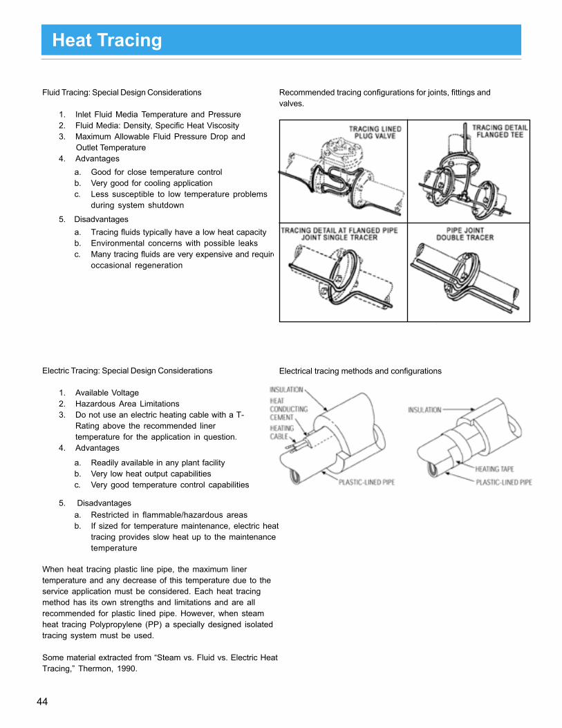
44
Fluid Tracing: Special Design Considerations
1. Inlet Fluid Media Temperature and Pressure2. Fluid Media: Density, Specific Heat Viscosity3. Maximum Allowable Fluid Pressure Drop and
Outlet Temperature4. Advantages
5. Disadvantages
a. Good for close temperature controlb. Very good for cooling applicationc. Less susceptible to low temperature problems
during system shutdown
a. Tracing fluids typically have a low heat capacityb. Environmental concerns with possible leaksc. Many tracing fluids are very expensive and require
occasional regeneration
Electric Tracing: Special Design Considerations
1. Available Voltage2. Hazardous Area Limitations3. Do not use an electric heating cable with a T-
Rating above the recommended linertemperature for the application in question.
4. Advantages
5. Disadvantages
When heat tracing plastic line pipe, the maximum linertemperature and any decrease of this temperature due to theservice application must be considered. Each heat tracingmethod has its own strengths and limitations and are allrecommended for plastic lined pipe. However, when steamheat tracing Polypropylene (PP) a specially designed isolatedtracing system must be used.
Some material extracted from “Steam vs. Fluid vs. Electric HeatTracing,” Thermon, 1990.
a. Readily available in any plant facilityb. Very low heat output capabilitiesc. Very good temperature control capabilities
a. Restricted in flammable/hazardous areasb. If sized for temperature maintenance, electric heat
tracing provides slow heat up to the maintenancetemperature
Recommended tracing configurations for joints, fittings andvalves.
Electrical tracing methods and configurations
Heat Tracing

45
Plastic-lined pipe is often insulated to prevent freezing, saveenergy or maintain a certain process temperature. Someoperating experience has shown that heat tracing andinsulating can also reduce permeation rates by lowering thetemperature differential across the pipe wall.
If installed improperly, however, insulation may block the pathsfor venting permeants on most PTFE-lined components.Under conditions which favor high permeation rates, blockageof the vent path can lead to high exterior steel shell corrosionrates, liner collapse and ultimately to premature failure of thelined components.
All PTFE/PFA-lined pipe and PTFE/PFA-lined fittings arevented via vent holes in the pipe, casting or fabricated steelshell. Welded half couplings and vent extenders can be usedto extend the vent path through insulation on pipe or aroundfittings, as shown in Illustration A & B. Couplings are availableas 3000lb. 1/8" or 1/4" sizes.
A. Vent holes and couplings on PTFE-lined pipe
B. Vent extender for fittings
Insulation and Venting

46
Initial Procedures for Flaring PTFE / PP / PVDF Lined Pipe** PFA-lined pipe can be field fabricated using different tooling and procedures - consult factory.
Field Fabrication Procedures

47
Field Fabrication Procedures
1XX999, DI threaded flange, can be screwed

48
Field Fabrication Procedures
Note: When flaring polypropylene, caution should be taken not to apply excessive torque to the wrench, which could result in forcing the flaring head in too quickly.
Heating and Flaring
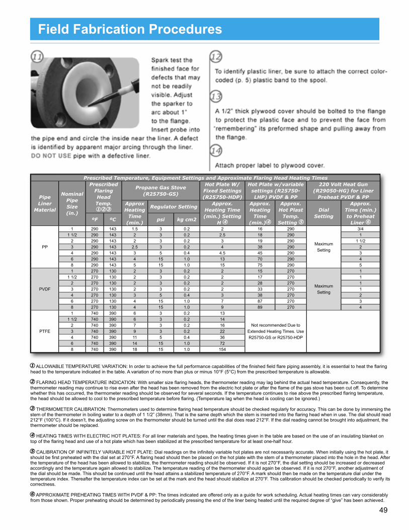
49
1 ALLOWABLE TEMPERATURE VARIATION: In order to achieve the full performance capabilities of the fi nished fi eld fl are piping assembly, it is essential to heat the fl aring head to the temperature indicated in the table. A variation of no more than plus or minus 10°F (5°C) from the prescribed temperature is allowable.
2 FLARING HEAD TEMPERATURE INDICATION: With smaller size fl aring heads, the thermometer reading may lag behind the actual head temperature. Consequently, the thermometer reading may continue to rise even after the head has been removed from the electric hot plate or after the fl ame of the gas stove has been cut off. To determine whether this has occurred, the thermometer reading should be observed for several seconds. If the temperature continues to rise above the prescribed fl aring temperature, the head should be allowed to cool to the prescribed temperature before fl aring. (Temperature lag when the head is cooling can be ignored.)
3 THERMOMETER CALIBRATION: Thermometers used to determine fl aring head temperature should be checked regularly for accuracy. This can be done by immersing the stem of the thermometer in boiling water to a depth of 1 1/2” (38mm). That is the same depth which the stem is inserted into the fl aring head when in use. The dial should read 212°F (100°C). If it doesn’t, the adjusting screw on the thermometer should be turned until the dial does read 212°F. If the dial reading cannot be brought into adjustment, the thermometer should be replaced.
4 HEATING TIMES WITH ELECTRIC HOT PLATES: For all liner materials and types, the heating times given in the table are based on the use of an insulating blanket on top of the fl aring head and use of a hot plate which has been stabilized at the prescribed temperature for at least one-half hour.
5 CALIBRATION OF INFINITELY VARIABLE HOT PLATE: Dial readings on the infi nitely variable hot plates are not necessarily accurate. When initially using the hot plate, it should be fi rst preheated with the dial set at 270°F. A fl aring head should then be placed on the hot plate with the stem of a thermometer placed into the hole in the head. After the temperature of the head has been allowed to stabilize, the thermometer reading should be observed. If it is not 270°F, the dial setting should be increased or decreased accordingly and the temperature again allowed to stabilize. The temperature reading of the thermometer should again be observed. If it is not 270°F, another adjustment of the dial should be made. This should be continued until the head attains a stabilized temperature of 270°F. A mark should then be made on the temperature dial under the temperature index. Thereafter the temperature index can be set at the mark and the head should stabilize at 270°F. This calibration should be checked periodically to verify its correctness.
6 APPROXIMATE PREHEATING TIMES WITH PVDF & PP: The times indicated are offered only as a guide for work scheduling. Actual heating times can vary considerably from those shown. Proper preheating should be determined by periodically pressing the end of the liner being heated until the required degree of “give” has been achieved.
Prescribed Temperature, Equipment Settings and Approximate Flaring Head Heating Times
Pipe Liner
Material
Nominal Pipe Size (in.)
Prescribed Flaring Head Temp. 1 2 3
Propane Gas Stove (R25750-GS)
Hot Plate W/ Fixed Settings (R25750-HDP)
Hot Plate w/variable settings (R25750-LHP) PVDF & PP
220 Volt Heat Gun (R29050-HG) for Liner
Preheat PVDF & PPApprox Heating
Time (min.)
Regulator SettingApprox.
Heating Time (min.) Setting
H 4
Approx. Heating
Time (min.) 4
Approx. Hot Plast
Temp. Setting 5
Dial Setting
Approx. Time (min.) to Preheat
Liner 6ºF ºC psi kg cm2
PP
1 290 143 1.5 3 0.2 2 16 290
Maximum Setting
3/41 1/2 290 143 2 3 0.2 2.5 18 290 1
2 290 143 2 3 0.2 3 19 290 1 1/23 290 143 2.5 3 0.2 4 38 290 24 290 143 3 5 0.4 4.5 45 290 36 290 143 4 15 1.0 13 70 290 48 290 143 5 15 1.0 15 75 290 5
PVDF
1 270 130 2 3 0.2 2 15 270
Maximum Setting
11 1/2 270 130 2 3 0.2 2 17 270 1
2 270 130 2 3 0.2 2 28 270 13 270 130 2 3 0.2 2 33 270 14 270 130 3 5 0.4 3 38 270 26 270 130 4 15 1.0 7 87 270 38 270 130 4 15 1.0 9 89 270 4
PTFE
1 740 390 6 3 0.2 13
Not recommended Due to Extended Heating Times. Use R25750-GS or R25750-HDP
1 1/2 740 390 6 3 0.2 142 740 390 7 3 0.2 163 740 390 9 3 0.2 224 740 390 11 5 0.4 366 740 390 14 15 1.0 728 740 390 18 15 1.0 154
Field Fabrication Procedures

50
Equipment Type Item No. Tooling Description PSI Part
No. Liner Used to Fabricate
Pipe Expander Pipe expander is used to prevent liner from slipping during forming operation. Pipe Expander
1a 1” EXPANDER R29620-016-1 PP PVDF PTFE
1b 1½” EXPANDER R29620-024-1 PP PVDF PTFE
1c 2” EXPANDER R29620-032-1 PP PVDF PTFE
1d 3” EXPANDER R29620-048-1 PP PVDF PTFE
1e 4” EXPANDER R29620-064-1 PP PVDF PTFE
Cut Off Ring Cut off ring is used to measure cut length for pipe liner.
2a 1” CUT-OFF RING R29650-016-6 PP PVDF PTFE
2b 1½” CUT-OFF RING R29650-024-6 PP PVDF PTFE
2c 2” CUT-OFF RING R29650-032-6 PP PVDF PTFE
2d 3” CUT-OFF RING R29650-048-6 PP PVDF PTFE
2e 4” CUT-OFF RING R29650-064-6 PP PVDF PTFE
Flaring Head Flaring Head used to shape the liner face fl at to the fl ange.
3a 1” FLARING HEAD R29650-016-3 PP PVDF PTFE
3b 1½” FLARING HEAD R29650-024-3 PP PVDF PTFE
3c 2” FLARING HEAD R29650-032-3 PP PVDF PTFE
3d 3” FLARING HEAD R29650-048-3 PP PVDF PTFE
3e 4” FLARING HEAD R29650-064-3 PP PVDF PTFE
Drive Plug Drive plug is used to push the liner along the inside of the pipe.
4a 1” DRIVE PLUG R28650-016-4 PP PVDF PTFE
4b 1½” DRIVE PLUG R28650-024-4 PP PVDF PTFE
4c 2” DRIVE PLUG R28650-032-4 PP PVDF PTFE
4d 3” DRIVE PLUG R28650-048-4 PP PVDF PTFE
4e 4” DRIVE PLUG R28650-064-4 PP PVDF PTFE
T-Wrench T-Wrench is used to tighten the expander assembly until it is locked into place.
5a 1” T-WRENCH R28650-016-2 PP PVDF PTFE
5b 1½”-3” T-WRENCH R28650-032-2 PP PVDF PTFE
5c 4” T-WRENCH R28650-064-2 PP PVDF PTFE
Field Fabrication Tooling

51
Equipment Type Item No. Tooling Description PSI Part
No. Liner Used to Fabricate
6 Thermometer R25750-T PP PVDF PTFE
Drive Plug Handle Drive Plug Handle
7 Drive Plug Handle R25750-5 PP PVDF PTFE
Pin Punch Pin Punch is used to prevent rotation of the rod while expander adjusting nut is being tightened.
8a PIN PUNCH ¼” (1½-3”) R25750-PP-2 PP PVDF PTFE
8b PIN PUNCH 3/8” (4” UP) R25750-PP-3 PP PVDF PTFE
Extension Bar Placed over handle of pin punch to develop additional leverage.
9a EXTENSION BAR (1½-3”) R28650-29 PP PVDF PTFE
9b EXTENSION BAR (1½-3”) R28650-30 PP PVDF PTFE
Thread Compound Thread compound is used to prevent the fl anges from rotating out of position when a straight pipe is used.
10 Thread Compound R25750-L PP PVDF PTFE
Storage Box Storage box is used to store all tooling used to fi eld fl are plastic-lined piping.
11a Storage Box 1”-4” R25750-B PP PVDF PTFE
11b 8” 7058480 PP PVDF PTFE
High Temperature Gloves High Temperature Gloves are used to handling hot fl aring head.
12 High Temperature Gloves R28760-G PP PVDF PTFE
Field Fabrication Tooling

Plastic LinedPipe and Fittings
D e s i g n M a n u a l
The information contained herein is provided only as a guide for the use of PSI products and does not constitute an express warranty of any kind. PSI specifically disclaims the implied warranty of merchantability and fi tness for a particular purpose.
Tefl on® is a registered trademark of E.I. du Pont de Nemours and Company and is used under license by PSI
ISO • LLOYDS • TUV • CE-PEDPSIOne Quality WayMarion, NC USA 28752Tel: (828) 724-2430Fax: (828) 724-2329
www.edlonpsi.com
L I N E D P I P I N G S Y S T E M S


