Page 1
54 How to Make World-Class Stretch Film
62 Get Your Robot Sized Right
66 Three Components Critical to Feeder Performance
VOL 61OCTOBER 2015 No- 10A property of Gardner Business Media
R&D ThermoformerTek Pak Takes Concepts to Production-Ready
Parts in Record Time
Page 2
Imagine the most complex part you can.
Then come to us for its mold.
At Canon Virginia, we’ve been designing, making and using high-
precision, high-volume injection molds for more than 20 years. This
expertise has been the foundation of our world-class products, and it’s
available to support your business as well. We provide personalized
engineering to help solve manufacturing challenges and develop the
mold you need for your complex plastic part. When you trust in Canon,
you’re partnering with a mold maker like no other.
Visit us online or call today to speak with a certifed Canon
representative to discuss your specifc needs.
cvi.canon.com | 1.866.99.CANON
Canon is a registered trademark of Canon Inc. in the United States. © 2015 Canon Virginia, Inc. All Rights Reserved.
Page 3
VOLUME 61 • NUMBER 10
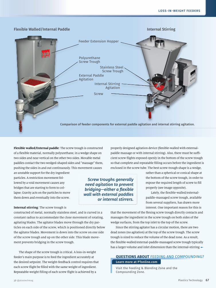
To Improve Feeder Performance, Start by Understanding Three Key Components
These are the screw trough, agitator,
and the screw itself. It’s crucial to
understand the diferent types and
the advantages/disadvantages of each.
By Walt Folkl & Andy Kovats,
Brabender Technologie Inc.
On-Site
R&D Thermoformer:
Tek Pak Is Launch Pad
For New Products
Toolmaker and thermoformer takes
concepts to production-ready parts
in record time.
By Matthew H. Naitove,
Executive Editor
66
62
46
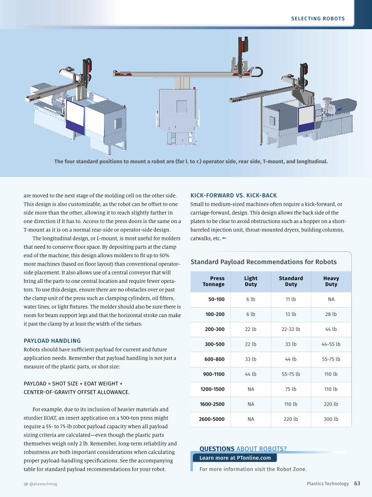
Spec’ing a Robot? Match It
To Your Press Size & Project
Where is your business today?
What might tomorrow’s molding
projects look like? These are
among the questions you need to
answer when deciding what style
robot is best for you.
By Jason Long, Wittmann Battenfeld USA
4 FROM THE EDITOR
8 STARTING UP
CLOSE-UP
14 Injection Molding
20 Predictive Maintenance
24 Sustainability
KNOW HOW
28 Materials
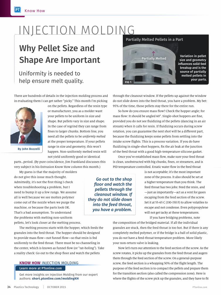
34 Injection Molding
38 Extrusion
42 Tooling
KEEPING UP WITH TECHNOLOGY
70 Injection Molding
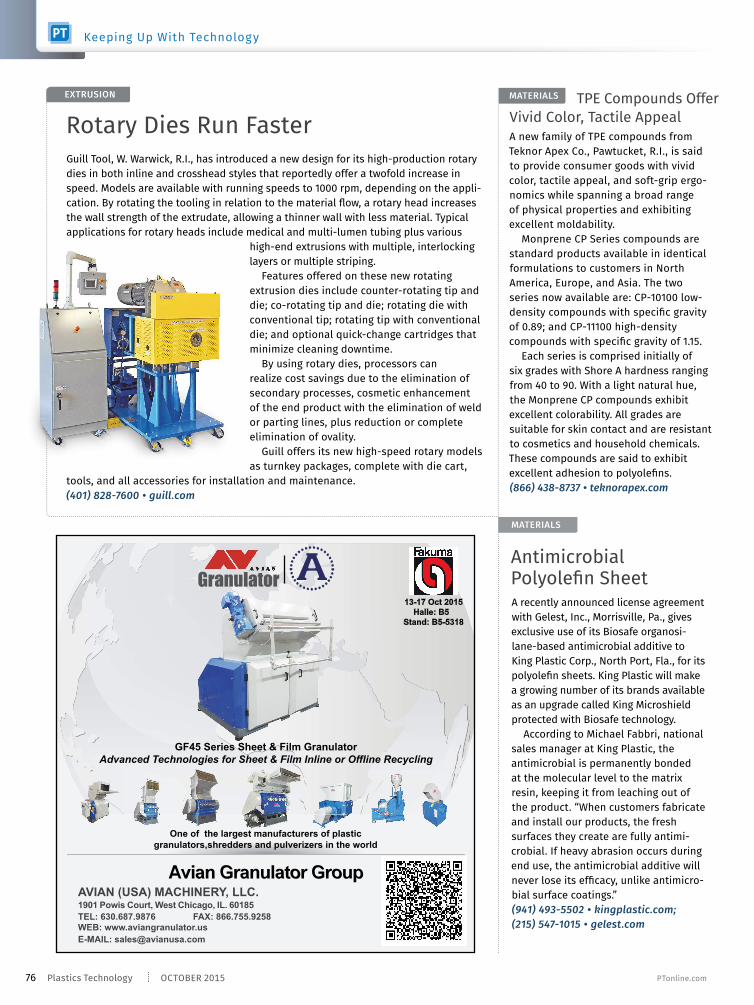
72 Extrusion
72 Compounding
72 Thermoforming
72 Feeding
74 Material Handling
74 Testing/Measuring
74 Size Reduction
75 Materials
78 Tooling
YOUR BUSINESS
79 Resin Pricing Analysis
81 Processors’ Business Index
82 Market Watch
83 Marketplace
88 Processor’s Edge
Here’s What You Need to Know To
Make World-Class Stretch Film
Advances in materials, feedblock/die
technologies, and winding can help
processors develop more sophisticated
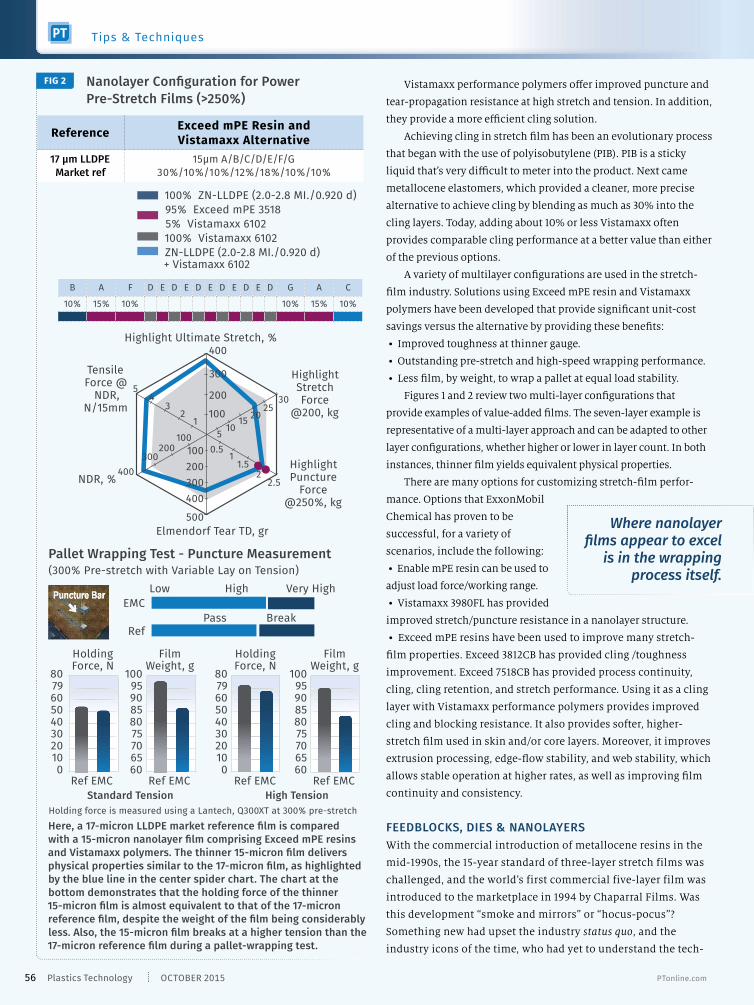
cast-stretch products.
By Trudy Iaccino, ExxonMobil Chemical Co.
Peter F. Cloeren, Cloeren Incorporated
Dr. Frank Hoffmann, Windmoeller & Hoelscher
54Tips and Techniques
Tips and Techniques
Tips and Techniques
PTonline.com 1Plastics Technology
Page 4
HEADQUARTERS6915 Valley Avenue
Cincinnati OH 45244-3029Phone 513-527-8800
Fax 513-527-8801 gardnerweb.com
NEW YORK OFFICES1441 Broadway, Room 3037New York, NY 10018 Phone 646-827-4848 Fax 513-527-8801 ptonline.com
PLASTICS TECHNOLOGY IS PROPERTY OF
President Rick Kline, CBC
COO Melissa Kline Skavlem
Group Publisher Rick Kline, Jr.
Senior V.P., Content Tom Beard
Director of Market Intelligence Steve Kline, Jr.
Treasurer Ernie Brubaker
Advertising Manager Bill Caldwell
Circulation Director Ross Jacobs
Director of Information Services Jason Fisher
Senior Managing Editor Kate Hand
Creative Director Jeff Norgord
Creative Department Manager Rhonda Weaver
Senior Marketing Manager Dave Necessary
Senior Event Manager Allison Kline Miller
Plastics Technology Handbook NPE Offcial Show Directory
Modern Machine Shop IMTS Directory
Moldmaking Technology CompositesWorld
Automotive Design & Production Production Machining
Products Finishing Products Finishing Directory
GARDNER BUSINESS MEDIA ALSO PUBLISHES
ptonline.com @plastechmag
publisher Rick Kline, Jr. [email protected]
associate publisher Jim Callari
editorial director [email protected]
executive editor Matthew Naitove [email protected]
senior editors Lilli Manolis Sherman [email protected]
Tony Deligio [email protected]
Heather Caliendo [email protected]
advertising sales Lou Guarracino [email protected]
Rick Brandt [email protected]
Ryan Delahanty [email protected]
Jackie Dalzell [email protected]
art director Sheri Kuchta Briggs [email protected]
marketing manager Kim Hoodin [email protected]
ad production manager Becky Helton [email protected]
circulation manager Christina Castrucci [email protected]
www.TiniusOlsen.com
The first name in materials testing.
Busted!This company’s QA program AND reputation
Like Humpty Dumpty, it is hard to put the pieces back together once a
real world product quality disaster strikes. The ultimate cost of a recall
will be far, far greater than any savings from cutting corners or not
investing in a quality assurance program in the first place. With our
broad spectrum of physical testing machines, software, and technical
support, Tinius Olsen can help you assure quality from material to end
product. To international standards and your toughest specifications.
Reputations (yours and ours) depend on it.
• Keep up on the issues affecting mold manufacturing.
• Interact with industry leaders and newcomers alike.
• Share insights, observations, challenges and
solutions with your peers.
Participate in the MMT Blog
The MoldMaking Technology Blog
is designed for you, allowing you to participate
in a dialogue among professionals in the
mold manufacturing industry.
Join the Discussion!
MoldMakingTechnology.com/Blog
2 OCTOBER 2015Plastics Technology PTonline.com
Page 6
The clock is ticking and seats (and hotel rooms) are flling up.
Have you checked out Plastics Technology’s upcoming Extrusion
2015 Conference? If not, do it now (a two-
page advertisement on p. 32-33 of this
issue will give you the skinny). It’s going
to be held Nov. 2-3 in Charlotte, N.C., at
the Omni Charlotte Hotel in the down-
town section of the city.
This two-day event is packed with
presentations from more than 60 tech-
nical experts, covering a wide range of
subject areas. The morning sessions on
each day will include presentations on
general extrusion topics. During each
afternoon there will be three concurrent breakout sessions that
hone in on your particular process: flm/sheet; pipe/profle/
tubing; and compounding.
If you extrude sheet or flm, these two afternoon sessions
will give you the opportunity to learn more about best practices
in winding, drying, purging, product changeovers, and trouble-
shooting nettlesome issues such as gels and black specs, as well as
new developments in no-dry systems for PET, and much more.
If you extrude pipe, profle or tubing, these two afternoon
sessions are an opportunity to learn more about best practices
in quick changeovers, drying, downstream systems for sizing,
pulling and
cutting,
and even
“direct”
extrusion
technology that combines compounding with pipe processing.
And if you’re involved in compounding you’ll have access to
presentations on running flled compounds, conveying dusty
materials like TiO2, new developments in pelletizing, break-
throughs in single-screw compounding, plus troubleshooting tips
on venting, dust removal, and a range of other topics.
But don’t sleep in, because there is plenty on the agenda
each morning for you, too: screw-design basics, troubleshooting
conveying systems, new developments in fltration and melt-pump
technologies, how to make more efcient use of reclaim, new
approaches to foaming, and more.
In addition to the technical program, there will be ample oppor-
tunity for you to mingle with the more than 40 companies that will
be exhibiting at this event.
You can log on to PTonline.com to download a copy of the entire
program, see a list of all of the companies that are exhibiting, learn
about pricing details, and register.
In terms of accommodations, once again it’s best to act
quickly. The Omni is the show hotel, but has sold out. As a result,
we have negotiated a similar discounted rate with the Aloft
Charlotte, which is nearby.
We at Plastics Technology believe the Extrusion 2015 Conference
is the event of the year for extrusion processors of all kinds. Don’t
miss it. We hope to see you there.
FOLLOW US @plastechmag
Don’t sleep in, because there is plenty on the agenda each morning for you.
Don’t Waste Any More Time: Register Now for the Extrusion 2015 Conference
Jim Callari
Editorial Director
Source: Davis-Standard
Don’t miss out on the technical event of the year in extrusion.
Source: Davis-Standard
4 OCTOBER 2015Plastics Technology PTonline.com
From The Editor
Page 7
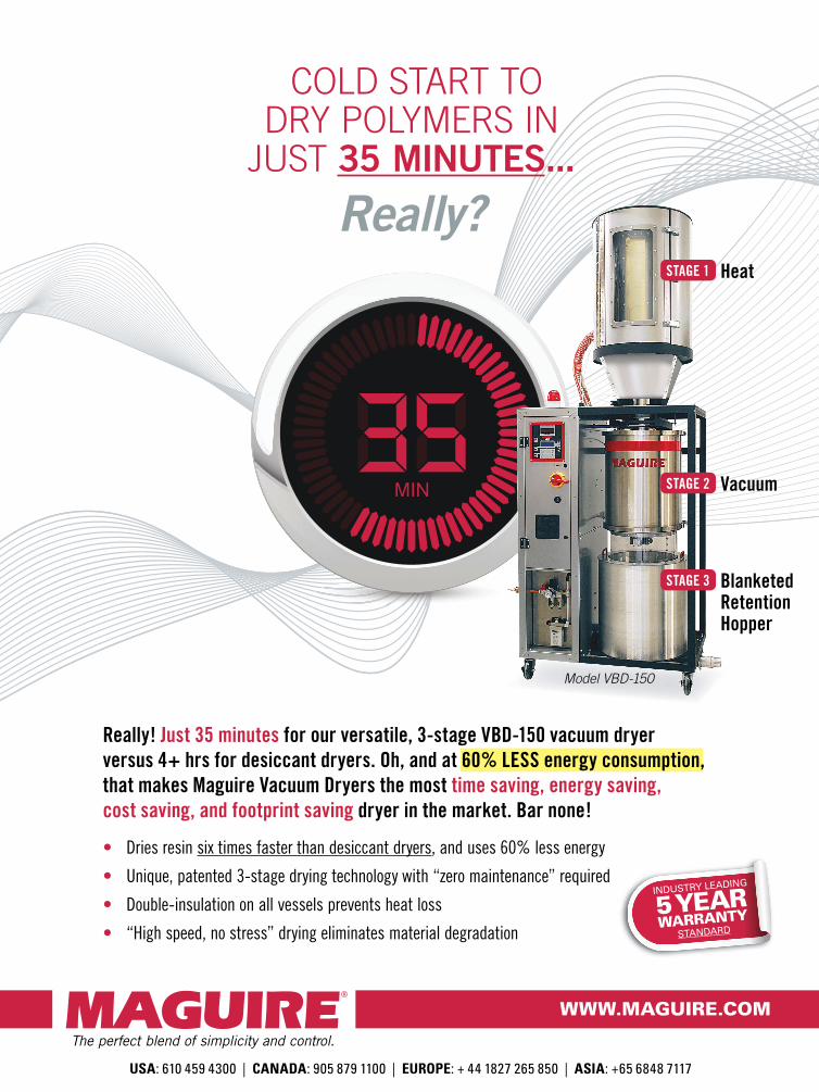
Really! Just 35 minutes for our versatile, 3-stage VBD-150 vacuum dryer
versus 4+ hrs for desiccant dryers. Oh, and at 60% LESS energy consumption,
that makes Maguire Vacuum Dryers the most time saving, energy saving,
cost saving, and footprint saving dryer in the market. Bar none!
• Dries resin six times faster than desiccant dryers, and uses 60% less energy
• Unique, patented 3-stage drying technology with “zero maintenance” required
• Double-insulation on all vessels prevents heat loss
• “High speed, no stress” drying eliminates material degradation
Heat
Vacuum
Blanketed Retention Hopper
MIN
COLD START TO
DRY POLYMERS IN
JUST 35 MINUTES...
Really?
INDUSTRY LEADING
5 YEARWARRANTY
STANDARD
USA: 610 459 4300 | CANADA: 905 879 1100 | EUROPE: + 44 1827 265 850 | ASIA: +65 6848 7117
STAGE 1
STAGE 2
STAGE 3
Model VBD-150
The perfect blend of simplicity and control.
WWW.MAGUIRE.COM
Page 8
© Copyright 2014 Novatec, Inc.
Novatec IS Plastics C
Page 9
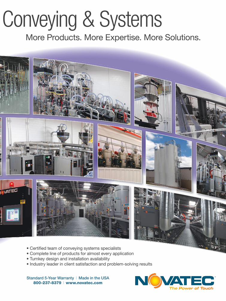
More Products. More Expertise. More Solutions.
• Certifed team of conveying systems specialists
• Complete line of products for almost every application
• Turnkey design and installation availability
• Industry leader in client satisfaction and problem-solving results
Standard 5-Year Warranty | Made in the USA
800-237-8379 | www.novatec.com
s Conveying & Systems
Page 10
Trexel Adds Chemical Foaming Agent to Its Product Line
Trexel, Inc., Wilmington, Mass., a long-time proponent
of physical foaming with its MuCell direct gas-injection
process, has now added chemical foaming to its micro-
cellular technology portfolio. Trexel has partnered with
masterbatch producer Polyfl Corp., Rockaway, N.J., which
has offered EcoCell
blowing-agent
concentrates since
2009. Polyfl’s
patented technology
uses 0.08-micron
nanoparticles of
calcium carbonate
in an endothermic
reaction that yields
only carbon dioxide,
water, and citric
salts, whereas most
endothermic chemi-
cal foaming agents
(CFAs) reportedly
also produce soda
ash, which can cause plateout and corrosion. Besides being
a “cleaner” reaction, EcoCell is said to produce smaller cell
sizes and more uniform cell distribution. Trexel describes it
as a microcellular cell structure of 20-80 microns.
While Polyfl will contine to market its EcoCell CFA
for extrusion, Trexel will now offer it under the TecoCell
name for injection molding and automotive blow molding
of products like ducts. Weight reductions with TecoCell
are typically 7-10% in injection molding (compared with
more than 20% density reductions commonly achieved
with MuCell) and 30-35% in accumulator blow molding.
TecoCell reacts at 200-280 C (392-536 F), suiting it mainly
to PE and PP, whereas MuCell is also used with higher-
temperature engineering resins. TecoCell also works well
with unflled resins, whereas MuCell is generally used with
flled or reinforced
materials.
Trexel says MuCell
and TecoCell are
complimentary
rather than compet-
ing technologies.
TecoCell requires
no equipment
modifcation, unlike
MuCell, which needs
a modifed screw
and barrel. That
gives TecoCell an
economic advantage
for low-volume jobs
using unflled or
talc-flled PE and PP. But once the equipment investment
for MuCell is made, the ongoing costs of MuCell nitrogen
injection are lower—typically less than 1¢/part vs. 3-9¢/lb
added cost for 1-3% use levels of TecoCell. Because nitro-
gen is a more effcient foaming agent than CO2, MuCell
will generally produce higher foaming levels and density
reduction, according to Trexel. MuCell is also said to be
superior in reducing warpage, but TecoCell may produce
better surface fnish—although not Class A.
(800) 733-2946 • trexel.com; (866) 765-9345 • polyflcorp.com
Purging Compound Developed For FDM 3D Printers
In collaboration with 3Dom USA, Fargo,
N.D., Schuman Plastics’ Dyna-Purge
Div., Depew, N.Y., has introduced a new
grade of non-abrasive, non-chemical,
FDA-compliant thermoplastic purging
compound specially formulated for FDM
(Fused Deposition Modeling) 3D printers.
FDM printers extrude a fne thread of
molten plastic, which is deposited in
layers to build up a part.
Dyna-Purge 3D Clean is suited to
3D printing applications that require
multiple color and resin changes. The
new compound is designed to purge all
resins used in 3D printing. It is report-
edly easy to use before or after printing a
part, for color or resin changes (espe-
cially involving composite materials such
as glass-flled nylons), and for preventive
machine maintenance. It has a wide
processing-temperature range, from 320
to 575 F. It comes in 8-in.-long strands of
1.75- or 2.85-mm diam.
(716) 685-2121 • dynapurge.com
TecoCell in PP
8 OCTOBER 2015Plastics Technology PTonline.com
TECHNOLOGY AND INDUSTRY NEWS
Starting Up
Page 11
[email protected]
201-345-5229www.fabricating.com America’s must trusted marketplace for custom parts.
Want to meet new customers looking for shops like yours?
Partner with us. We’re in the business of connecting
plastic parts buyers to U.S. suppliers. Nobody does
it better. Fabricating.com is where AMERICAN manufacturers
go to fnd powerful business leads and meet major OEMs.
That’s right. We’re U.S. only.
Engineers and other purchasing professionals are
searching for plastic processors right now
on Fabricating.com. Let them fnd you.
Register to meet them today at www.fabricating.com/supplier.
Buyers are looking for U.S. parts suppliers RIGHT NOW!
Page 12
RTP Offers Tribology Data for Medical Material Selection
An innovative friction test that predicts
sliding behavior in plastic single-
use drug-delivery devices has been
developed by RTP Company, Winona,
Minn. Molders, designers, and OEMs are
keenly aware of how stick-slip phenom-
ena, or “stiction,” can affect the perfor-
mance of devices such as auto-injectors,
injection pens, stop cocks, and safety
syringes. Until recently, RTP says, there
were no established industry tests that
accurately predicted friction behavior
(tribology) in such devices, making
material selection diffcult.
Using the new test method, RTP
characterized the tribology of PC, acetal,
ABS, PC/ABS, HDPE, and PBT. These
resins were tested in a variety of combi-
nations with friction-reducing additives
including PTFE, PFPE (perfuoropoly-
ether) oil, and a selection of silicones,
along with RTP’s own All Polymeric
Wear Alloy (APWA Plus). RTP measured
the static and dynamic coeffcients
of friction of various combinations of
resins and friction-reducing additives.
The threshold representing the smallest
delta between the two measurements
has been dubbed by RTP tribologists
the “Glide Factor.” Tests showed that
the optimal friction pairings exhibited
low static coeffcient of friction (≤ 0.15)
and a Glide Factor of ≤ 0.015.
RTP is making data from these tests
available to help choose the correct
low-friction thermoplastics for medical
applications so that single-use devices
will perform more consistently without
the need for external lubrication.
(507) 454-6900 • rtpcompany.com
High-Moisture-Barrier
HDPE Gains In Flexible
Food PackagingA bimodal homopolymer HDPE that
features up to 50% higher moisture barrier
than standard resins has gained signif-
cant ground as a barrier layer in multilayer
fexible food packaging, particularly in
easy-open cereal and cracker packages.
Surpass HPs167-AB, a 1.2 MI, 0.966 g/cc
resin for blown flm from Nova Chemi-
cals, Moon Township, Pa., is one of the
high-barrier materials made with Nova’s
Advanced Sclairtech dual-reactor process
and single-site catalyst. Referred to as
sHDPE, HPs167-AB material has seen
signifcant growth in commercial packag-
ing applications in the last two years.
Typical dry-goods packages are three-
layer coextruded blown flms with a
peelable seal layer and an HDPE core layer.
According to Dan Falla, Nova technical-
service specialist, the thickness of the
HDPE typically determines the moisture-
vapor transmission rate (MVTR) of the
flm. “Traditionally, the HDPE layer was
conventional HDPE. The HPs167-AB resin
is quickly becoming the resin of choice
for a PE moisture barrier.” In many cases,
it is desirable to use the sHDPE together
with EVOH, as the sHDPE protects the
EVOH from having its barrier properties
weakened by moisture.
Falla says the sHDPE is stiffer than
typical HDPEs for multilayer packaging
flms, so it enables downgauging without
making the flm too soft to run easily
through vertical form/fll/seal machines.
His fndings are contained in a paper,
“Sealable Seal Films with Enhanced
Moisture Barrier Properties for Flexible
Packaging Applications,” presented at the
SPE ANTEC in Orlando in March.
(412) 490-4000 • novachem.com
Trex Launches Recycled LLDPE CompoundsTrex Company, Winchester, Va., maker of wood-plastic composite decking and railing and
one of the largest recyclers of post-consumer and post-industrial polyethylene, has
begun selling recycled plastics compounds. The company is using its excess recycled raw
material to produce LLDPE pellets as a new business venture.
Says Dave Heglas, sr. dir. of material resources,
“We envision numerous applications for our recy-
cled pellets,” such as trash bags and other bags, as
well as molded products such as bins, totes, and
even kayaks. He also sees considerable potential in
the manufacture of both rigid and fexible tubing,
such as agricultural drip tape. Trex already has
four lines dedicated to recycled pellet production,
making it one of the country’s largest producers of recycled LLDPE, and has plans to
add several more lines.
(800) 289-8739 • trex.com
BOPP Tailored for Thermoforming IMLA new flm designed specifcally for in-mold labeling in thermoforming is said to
deliver a look and feel comparable to injection molded products. Developed by
Treofan in Raunheim, Germany (treofan.com), the flm is a biaxially oriented poly-
propylene (BOPP) with a special surface layer that enables the thermoformed part
and label flm to fuse together at comparatively
low temperatures and pressures. Before this
flm innovation, BOPP could only be attached
to thermoformed containers in a separate step,
says Joachim Jung, product and business devel-
opment manager.
The surface of the new Treofan EPT flm
utilizes an undisclosed PP coextrusion. Treofan
commercialized the flm following a compre-
hensive series of tests with Illig, the thermo-
forming machinery maker. Unlike the paper and cardboard labels commonly used
in thermoforming, this BOPP can decorate the container on all fve sides (all four
lateral areas plus the bottom).
10 OCTOBER 2015Plastics Technology PTonline.com
TECHNOLOGY AND INDUSTRY NEWS
Starting Up
Page 13
The Global Advantage™ in
Extrusion & Converting
Exceptional value, consistent performance,
and outstanding service – that’s The Global
Advantage™. With installations on every continent,
our multinational team supports extrusion and
converting customers every step of the way.
With more than 70 years of industry experience,
our time-tested brand names and trusted reputation
are synonymous with quality. Professional design
engineers, laboratory personnel, training experts,
a talented commercial force, hands-on feld
technicians, and aftermarket parts and service
specialists comprise a powerful force with one
mission – to ensure you have what you need, when
you need it.
Contact us to learn how we can improve your process
and proftability.
#1 Extrusion Drive Pawcatuck, CT 06379 | +860.599.1010 | www.davis-standard.com | [email protected]
You’ve got a process…Davis-Standard can make it better!
Page 14
THE KEY TO
YOUR PROCESS
COOLING NEEDS
THE KEY TO
YOUR PROCESS
COOLING NEEDS
Davis-Standard Buys Gloucester Engineering
Davis-Standard LLC, Pawcatuck, Conn., recently announced it
had purchased Gloucester Engineering, Gloucester, Mass., from
investment frm Blue Wolf Capital. Until the early 1990s, Glouces-
ter was perhaps most recognized as a supplier of machinery for
commodity flm and bagmaking. It then evolved into supplying
more sophisticated lines for coextruded barrier systems, at one
point dominating that market. It then became a major supplier of
high-tech lines for cast stretch flm as well.
More recently, Gloucester has narrowed its focus to blown
flm, mainly on aftermarket services. To support this strategy, in
2012 it purchased Pearl Technologies, Savannah, N.Y., which makes
sizing cages, collapsing canopies,
and other products for blown
flm and bagmaking; and Future
Design, Mississauga, Ont., which
specializes in air rings.
“We’re excited about combin-
ing the strengths and market
reach of Davis-Standard and
Gloucester,” says Jim Murphy, D-S
president and CEO. “Glouces-
ter has always been a strong
company, so bringing their
technology and engineering
expertise to our operation is
signifcant for our combined
customer base. It also supports our ongoing goal of continuing to
provide equipment and service that improves process effciency
and proftability.”
Murphy adds, “The acquisition includes all of their designs
and technology: blown flm, cast flm, sheet, and foam sheet—all
areas where Gloucester Engineering has had a market presence
over the last several decades. We will be incorporating these into
the Davis-Standard product lines and focus Gloucester primarily
on its strongest area of blown flm. We will continue to support
the installed base of all Gloucester Engineering equipment.”
States Carl Johnson, Gloucester’s v.p. of sales, “The align-
ment of our companies
leverages our sizable base
of installed equipment
with the industry’s best
resources for sales, engi-
neering, and service. Both
companies have a reputa-
tion for strong people and
strong brands.” Johnson
referred to the D-S-
Gloucester combination
as a “game changer in the
global blown flm market.”
(860) 599-1010 •
davis-standard.com
TECHNOLOGY AND INDUSTRY NEWS
Starting Up
Page 15
TECHNOLOGY AND INDUSTRY NEWS
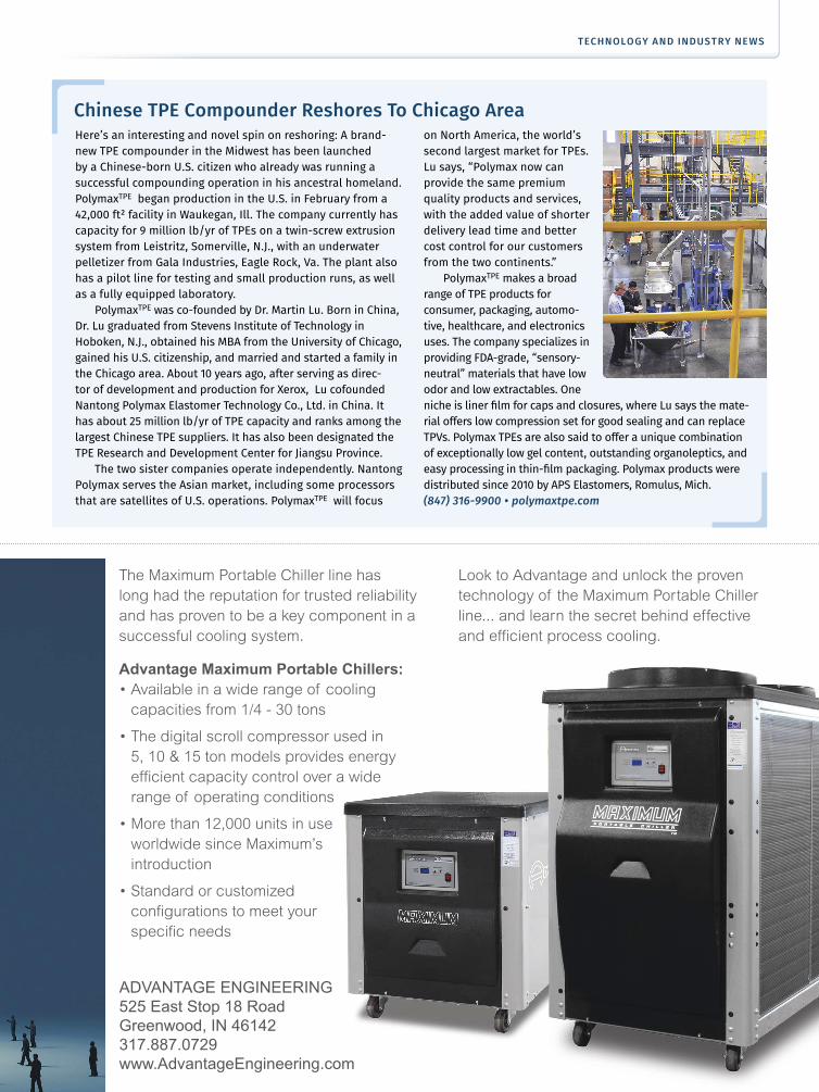
The Maximum Portable Chiller line has
long had the reputation for trusted reliability
and has proven to be a key component in a
successful cooling system.
Advantage Maximum Portable Chillers:
• Available in a wide range of cooling
capacities from 1/4 - 30 tons
• The digital scroll compressor used in
5, 10 & 15 ton models provides energy
effcient capacity control over a wide
range of operating conditions
• More than 12,000 units in use
worldwide since Maximum’s
introduction
• Standard or customized
confgurations to meet your
specifc needs
Look to Advantage and unlock the proven
technology of the Maximum Portable Chiller
line... and learn the secret behind effective
and effcient process cooling.
ADVANTAGE ENGINEERING
525 East Stop 18 Road
Greenwood, IN 46142
317.887.0729
www.AdvantageEngineering.com
Here’s an interesting and novel spin on reshoring: A brand-
new TPE compounder in the Midwest has been launched
by a Chinese-born U.S. citizen who already was running a
successful compounding operation in his ancestral homeland.
PolymaxTPE began production in the U.S. in February from a
42,000 ft² facility in Waukegan, Ill. The company currently has
capacity for 9 million lb/yr of TPEs on a twin-screw extrusion
system from Leistritz, Somerville, N.J., with an underwater
pelletizer from Gala Industries, Eagle Rock, Va. The plant also
has a pilot line for testing and small production runs, as well
as a fully equipped laboratory.
PolymaxTPE was co-founded by Dr. Martin Lu. Born in China,
Dr. Lu graduated from Stevens Institute of Technology in
Hoboken, N.J., obtained his MBA from the University of Chicago,
gained his U.S. citizenship, and married and started a family in
the Chicago area. About 10 years ago, after serving as direc-
tor of development and production for Xerox, Lu cofounded
Nantong Polymax Elastomer Technology Co., Ltd. in China. It
has about 25 million lb/yr of TPE capacity and ranks among the
largest Chinese TPE suppliers. It has also been designated the
TPE Research and Development Center for Jiangsu Province.
The two sister companies operate independently. Nantong
Polymax serves the Asian market, including some processors
that are satellites of U.S. operations. PolymaxTPE will focus
on North America, the world’s
second largest market for TPEs.
Lu says, “Polymax now can
provide the same premium
quality products and services,
with the added value of shorter
delivery lead time and better
cost control for our customers
from the two continents.”
PolymaxTPE makes a broad
range of TPE products for
consumer, packaging, automo-
tive, healthcare, and electronics
uses. The company specializes in
providing FDA-grade, “sensory-
neutral” materials that have low
odor and low extractables. One
niche is liner flm for caps and closures, where Lu says the mate-
rial offers low compression set for good sealing and can replace
TPVs. Polymax TPEs are also said to offer a unique combination
of exceptionally low gel content, outstanding organoleptics, and
easy processing in thin-flm packaging. Polymax products were
distributed since 2010 by APS Elastomers, Romulus, Mich.
(847) 316-9900 • polymaxtpe.com
Chinese TPE Compounder Reshores To Chicago Area
Page 16
Durina is president of Md
Plastics Inc., Columbiana, Ohio,
a frm that makes plasticating
components for injection
molding (mdplastics.com). He
is the exclusive manufac-
turer and marketer of sensors invented by Fred Buja, owner of
FJB PlasTechnology, Rochester, N.Y. The sensors, trade named
Temp-Tek, frst appeared at NPE 2012. Since then, Durina has been
working with Buja (formerly of Eastman Kodak) and a number of
molders and machinery OEMs to develop the technology for prac-
tical use. Md Plastics developed improved mounting hardware for
the sensors and has just released new monitoring
software designed to make them easy to use.
SENSING TOTAL ENERGY INPUT
The business end of this patented “thermoelastic”
sensor is a spherical bead of two metals, one mag-
netic and one nonmagnetic, that expands and con-
tracts under the infuence of both temperature and
pressure. According to Buja, the key principles are
that a temperature increase causes a volume increase
in the sensor bead, while a pressure increase on the
bead decreases its volume, which raises its internal
temperature (pressure x volume = temperature).
Durina demonstrates the sensor’s behavior in
a video on the frm’s website, in which he inserts a
sensor through a puncture in a tennis ball. When he
squeezes the ball, the sensor readings rise. Likewise,
he says, a sensor simply lying in the open on a
desktop will record a change in reading if the atmo-
spheric pressure changes.
The thermoelastic strain on the sensor bead from
both temperature and pressure is converted to a
temperature output reading, though it should more
properly be interpreted as a dimensionless unit of total
energy input from both heat and pressure. Durina notes that under
conditions in which the melt is under little or no pressure—such as
at the end of holding pressure before screw recovery starts—the
“Injection press controls today measure parameters like the
forward speed of the screw or plunger, the pressure applied, the
torque to run the screw, percentage ‘on’ time of the heater bands,
and so forth. Those are all machine variables.
What they don’t measure is the state of the
plastic itself.” According to Michael F. Durina,
that’s the key factor limiting molders’ ability to know in real time
whether they are producing good or bad parts. It would be much
more useful, in his view, to measure such factors as the melt
temperature, viscosity, melt density, and total energy input to
the melt during each cycle. The good news, Durina says, is that
technology has arrived to do just that.
By Matt NaitoveExecutive Editor
One example of a molding cycle recorded by a Temp-Tek nozzle sensor. The area under the curve for Pf calculation is variable by the user. The Te peak indicates when the mold is totally flled. The low point marked “Temperature” is where the screw is idle and the reading corresponds most closely to “pure” melt temperature, without the effect of pressure on the sensor.
QUESTIONS ABOUT INJECTION MOLDING?
Visit the Injection Molding Zone
New Sensor Technology Monitors State of the Melt During Molding
Detect ‘true’ melt temperature, viscosity variations, melt density,
and much more, throughout the molding cycle.
At last, a solution to ‘the mystery of melt temperature’ in an injection machine.
Cooling
Setting
A
FillingScrew Rotate
Screw Idle Temperature
Pack/Hold Starts
(Mold Filled)
14 OCTOBER 2015Plastics Technology PTonline.com
INJEC TION MOLDING
Close-Up On Technology
Page 17
®
PPEPPE
PPESOUTH
PPEW E S T
Toll Free: USA, Canada & Mexico
800-362-07068303 CORPORATE PARK DRIVE, MACEDONIA (Cleveland), OHIO 44056, U.S.A.216-367-7000 � Toll Free: 800-321-0562 � Fax: 216-367-7022 � Order Fax: 800-223-8305
6385 Montessouri Street, Las Vegas, Nevada 89113702-433-6385 � 800-258-8877 � Fax: 702-433-6388
11218 Challenger Avenue, Odessa, Florida 33556727-834-8888 � 800-282-6783 � Fax: 727-834-8873
www.ppe.com � [email protected] PROCESS EQUIPMENT, INC.PLASTIC PROCESS EQUIPMENT, INC.
Quality Products, Fair Prices & Best Service since 1974Quality Products, Fair Prices & Best Service since 1974
MACHINERY
SCREWS, TIPS, NOZZLES & MOLD SUPPLIES
AEROSOLS & CHEMICALS
MATERIAL HANDLING
MOLD WATERLINE COMPONENTS
CONTROLS, HEATERS & T.C.s
YOUR DEPENDABLE SOURCE FOR
MOLDING ACCESSORIESThe World�s Largest Variety of Accessories for the Plastics Industry!
95% OF ALL STOCK ORDERS SHIPPED THE SAME DAY!
YOUR DEPENDABLE SOURCE FOR
MOLDING ACCESSORIES95% OF ALL STOCK ORDERS SHIPPED THE SAME DAY!
The World�s Largest Variety of Accessories for the Plastics Industry!
Page 18
reading correlates most closely
with just melt temperature.
That was the experience
of Wayne Staupe, Technology
Center manager at Evco
Plastics in De Forest, Wis.
His group tested one of the
sensors in the nozzle of a
machine and compared the
sensor readings at the end
of holding pressure—where,
Staupe saw that sensor
output stabilized before
screw recovery—and found
they were consistently at the
center of the range of manual
readings from a temperature
probe in a purged shot taken by a group of technicians. “It was
pretty darn good,” Staupe concluded.
SOLVE THE ‘MYSTERY’ OF MELT TEMPERATURE
Staupe would be the frst to agree that there has been no econom-
ical way to accurately measure melt temperature in the injection
barrel or nozzle. A conventional sensor embedded in either loca-
tion would be infuenced by the surrounding steel temperature,
and a sensor projecting into the melt stream would be too suscep-
tible to wear or damage. Durina adds that conventional thermo-
couples are relatively slow to react. (A newly available, fush-
mounted infrared sensor is another alternative that may ofer
fewer limitations—see Keeping Up section.)
“The only practical way to measure melt temperature today is
by manually sticking a probe into a purge,” says Staupe. “That’s too
inaccurate because it’s subject to a large number of measurement
variables.”
Durina thinks the
Temp-Tek sensor can fnally
“solve the mystery of melt
temperature.” Staupe agrees:
“It’s the best thing I’ve seen for
measuring melt temperature inline.” Evco has just purchased two
more Temp-Tek sensors for evaluation at the tech center.
The stainless-steel-bodied sensor is typically mounted in a 1.5
mm (0.063 in.) diam. hole in the injection nozzle. Md Plastics devel-
oped a compression ftting for the sensor with a PTFE thermal barrier.
It screws into the mounting hole and withstands high internal barrel
pressures. The sensor is mounted tangent to the melt stream, with
only the very tip directly exposed to the melt, and is covered by a flm
of melt thinner than a human hair, which protects the sensor from
abrasion by the melt stream, fllers, etc.
According to Durina and Buja, the Temp-Tek sensor can reveal
much more than melt tempera-
ture. It can measure the total
amount of “work” (energy input)
imparted by the machine to
the melt throughout the whole
molding cycle. Durina reports
that a study at Tech Molded
Plastics in Meadville, Pa., showed
that the shape of the “total work”
curve from the Temp-Tek sensor
over the course of a cycle very
closely matched that of the
relative-viscosity output from an
RJG eDart system, which calcu-
lated “efective viscosity” for the
same cycle from injection speed,
pressure, and screw diameter.
(RJG Inc. is in Traverse City, Mich., rjginc.com). With appropriate
scaling, the two curves can be overlaid almost exactly.
Draexlmaier Automotive of America in Duncan, S.C., is using
a Temp-Tek nozzle sensor as an in-process quality check to detect
viscosity changes that would occur if there were a change in the blend
ratio of long-glass compound and unreinforced pellets being fed to a
4000-ton press. Otherwise, parts could be produced with insufcient
strength but no visible signs of the change in reinforcement loading.
Dennis Quinby, injection molding process engineering supervisor,
says the Temp-Tek sensor “works well and is very cost-efective for
what we’re trying to do.” He is also exploring the potential of the
sensor to indicate screw wear through a change in the thermal profle.
Another molder, which did not wish to be identifed, has been
using 16 Temp-Tek sensors in extensive development work. It uses
the sensors in the nozzle, mold vents, and hot-runner manifold
on the same machine. And, like other molders interviewed for this
article, the thermal sensor is being used together with cavity-pres-
sure sensors. A senior molding manager at the company, who has
30 years of experience and is a certifed expert in Scientifc Molding,
says the combined use of diferent sensors is enabling advances in
process monitoring: “We’re doing things no one else has done,” he
says, though he could not go into much detail. He did say, however,
that the Temp-Tek sensors provided an unprecedented capability
for “dynamic” thermal monitoring: “We can see things happen over
every phase of the cycle.”
Durina says the sensor can be used to detect changes in the
process caused by screw/barrel wear or batch-to-batch variations in
resin quality or moisture content. Durina’s new PC software makes
it easy to use the shape of the total-energy curve and the area under
the curve as QC tools. The software can run on a standard laptop.
It takes signals from a module into which up to 16 sensors can be
plugged, along with a 24V signal from the press at the start of injec-
tion. For startup of a new mold, the user would run until a good
Detect changes in melt viscosity or signs of screw/barrel wear.
Once a mold is producing good parts, the user can press the “Template” button to store that thermal energy curve as a quality standard. Users can also set tolerance bands around key points on the curve
16 OCTOBER 2015Plastics Technology PTonline.com
INJEC TION MOLDING
Close-Up On Technology
Page 19
October 20-21, 2015
Knoxville, TN USA
HIGHLIGHTS INCLUDE:
• Tour of Oak Ridge National Laboratory
• Tour of Local Motors
• More than 18 technical sessions
• Grand reception in Exhibitor Room
• Exhibitions and business networking
The Additive Manufacturing Conference examines additive technologies for
making functional components and end-use production parts. This two-day event
covers the equipment, the applications and the materials impacting current and
future additive applications.
More than 20 experts representing global
OEMs like GE Aviation, cutting-edge contract
manufacturers like Linear Mold & Engineering
and renowned research outfts like Oak Ridge
National Laboratory will provide in-depth
insights that will enable you and your
colleagues to adopt, expand or evolve your
additive manufacturing knowledge base.
PRESENTED BY:
CONFE RE NCE
Register & Learn @ AdditiveConference.com
SPECIAL OFFER – SAVE $150!
Use Promo Code: AMC15 0
R E G I S T E R T O D A Y !
Page 20
He also notes that an advantage of Temp-Tek sensors over
conventional in-mold sensors is that they can be placed anywhere
in the tool—at the parting line or even inside a slide or a pin. A
lower-cost solution, uniquely available with Temp-Tek sensors, is
that they can be located in the vents with little or no mold modif-
cation. There, they can measure the temperature of the vent gases
on each shot as a proxy for melt temperature.
Md Plastics has sold more than 20 sensors so far to a small
handful of molders. Nozzle sensors cost about $379 apiece, and
in-mold sensors under $300. Modules that send data to a PC come
with capacity to plug in up to 16 sensors. Price is under $7000 for
the module plus one nozzle sensor and monitoring software.
Md Plastics also recently signed its frst license with a machinery
OEM to integrate its Temp-Tek monitoring software with the injec-
tion press controls. PASL Windtech (P) Ltd. in Ahmedabad, India,
recently introduced its HM Series of servo toggle and hydromechanical
presses from 160 to 880 tons (pwsl.in). According to managing director
Abhishek Javeri, the Temp-Tek sensor is “something that has not been
ofered before in the ability to measure actual melt temperature at the
nozzle. We hope to ofer customers the ability to develop a thermal
template for a good part and then compare each subsequent part
to know if it is good or bad. We hope to ofer the nozzle sensor and
control software as a standard feature across our machine range.”
shot is produced consistently, and then hit a button marked “Create
Template.” This stores a sensor output curve for a good shot based on
75 readings/sec. (Higher sample rates can be provided as an option.)
After running several good shots, the user can go to the new
software’s Statistics page and examine the minimum, maximum,
and average values for two key parameters—the maximum point
in the cycle curve (Te) and the Power Factor (Pf), or area under the
curve. The user can then set
alarm limits for those factors,
but knowing where those
limits should be set requires
empirical data on how much
variation in those values will
produce a bad shot. Durina
says the Temp-Tek output
curves can show the instantaneous results on total energy input of
changes in backpressure, barrel temperature, screw speed, injec-
tion velocity, and melt decompression.
In complex, multicavity molds, Durina recommends putting a
sensor in both the nozzle and in the last cavity to fll, which can be
established via short shots. Sensor output gives an indication of melt
density in the cavity, which Durina says is “the best variable that can
be used to determine injection-pressure transfer from pack to hold.”
The new sensor can be placed anywhere in the
mold—in a vent at the parting line or even
inside a slide or a pin.
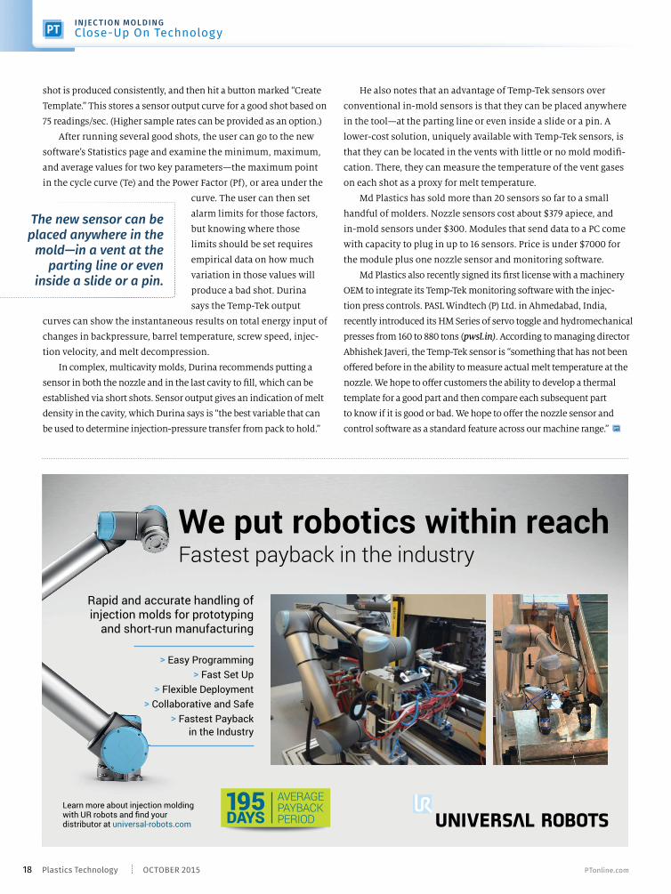
Learn more about injection molding with UR robots and fnd your distributor at universal-robots.com
We put robotics within reachFastest payback in the industry
Rapid and accurate handling of injection molds for prototyping
and short-run manufacturing
> Easy Programming
> Fast Set Up
> Flexible Deployment
> Collaborative and Safe
> Fastest Payback
in the Industry
AVERAGEPAYBACKPERIOD
195DAYS
18 OCTOBER 2015Plastics Technology PTonline.com
INJEC TION MOLDING
Close-Up On Technology
Page 21
Mold OPEN
Core Out
Mold CLOSED
Core OUT
Mold CLOSED
Core IN
Core PRE-LOADED
Against FULL
Injection Pressure
CAN’T DO IT!
CAN’T DO IT!
KOR-LOK® TRADITIONAL
SIDE-ACTION VS. SIDE-ACTION
SYSTEMS SYSTEMS
ZERO FLASHON THE FIRST SHOT
Be proactive – Reduce mold size and complexity ile eliminating tryout issues, mold t eaks, and expensive maintenance.
• 10x the Preload Power of standard cylinders.
• Low pressure preload activation – only 1,500 psi.
• Real Locking – Hydraulics may be removed.
• 100% preload at ZERO psi after lockup.
• Sensor verifi es unit is locked as expected.
• Easy mounting, preload adjustment and setup - No Shimming needed.
• Multiple Sensor & Hydraulic Ports – Standard.
• Rear porting for set and pull – Standard.
• Fast Delivery on ANY STROKE size.
• Easy Wiring – Dry Contact SPDT Switches – Standard.
NEW SIZE!100 SERIES
KOR-LOK®
SIDE-ACTION SYSTEMS
Designed & Made in USA
pfa-inc.com
N118 W18251 Bunsen DriveGermantown, WI 53022
(262) 250-4410Fax (262) 250-4409
KOR-LOK® , Hydra-Latch™ and Hydra-Jaws™ are trademarks of PFA, Inc.
©2013 PFA, Inc. All Rights Reserved.
3D Parametric CAD files now available online
VISIT OUR WEBSITE FOR
PFA'S ENTIRE FAMILY OF PRODUCTS
YES!
YES!
YES!
YES!
YES!
YES!
Page 22
testing, the new ESP Sensorlytics will apply a Cloud-based “deep
learning” technique to understand the physics of the maintenance
condition automatically. The software will also have a feld-learning
mode in which a user will be able to set the maintenance gauge
according to his/her best experience. In the self-learning mode,
Novatec said the system tries to ft data with physics of a known
anomaly; while in the reinforced-learning mode, a user trains the
system on what to show on the Predictive Maintenance Gauge.
Novatec notes that an ESP Sensorlytics beta version will be
available around November or December for selected customers.
The company’s ESP Sensorlytics Plus, which is a full pump predic-
tive-maintenance system will be available on the new Novatec
Silencer and VPDB positive-displacement vacuum pumps. With
ESP Sensorlytics Plus, users can check flter condition, oil level,
Shown at NPE2015 for the frst time, new technology that uses
wireless Cloud-computing sensors to analyze and predict equip-
ment failure garnered an overwhelming, and at times, surprising,
response (see February and May Close Ups). In
short, almost everyone who sat through the demo
of new predictive-maintenance technology at
Novatec’s booth was interested, but not everyone was as keen to
purchase new auxiliary equipment to avail themselves of it.
“We had so many people at our booth who said, ‘Well gee, I
have all these problems you’re describing, but what can I do about
them?’” says Conrad Bessemer, president of Baltimore-based
Novatec (novatec.com). “‘You can’t help me other than I’m going to
have to replace all my equipment.’”
To support processors interested in the technology but who
might not be in the market for all-new auxiliaries, Novatec and
its partner on the project, Prophecy Sensorlytics, Columbia, Md.
(prophecysensorlytics.com), have developed a retrofttable product
that can be added to machinery already in the feld, including
non-Novatec products.
Novatec says the new ESP Sensorlytics will detect specifc
issues that are typical with vacuum pumps, including problems
like worn bearings, which can cause a heaving friction and lead
to overheating of the motor, as well as poor oil viscosity or unsafe
pump operation. The so-called Pump Lite does this in the same
manner as the original Prophecy tech-
nology being deployed on new Novatec
equipment: by detecting anomalies in
vibration and magnetic feld.
Where it will difer from the tech-
nology shown at NPE2015 is the use of
what the company calls self-learning
and reinforced learning. At its R&D lab,
Novatec has studied its own pumps
and dryers, learning about their failure
modes and feeding that information into Prophecy’s algorithm so
that it knows what a low-oil vibration feels like, for instance.
To provide the same predictive maintenance for equipment
made by other OEMs, which has not been put through the same
By Tony Deligio
Senior Editor
Prophecy sensors can be installed on any type of industrial equipment to determine overall power factor as well as sag, surge, swallow, and crest factor, so defciencies can be identifed and corrected.
‘Wearable’ Machine SensorsExtended to Power Factor & Retrofts
As is often the case with a new technology, customers
are dictating how predictive-maintenance sensors will
be applied and where they might be headed next.
“Our focus is really on power,
air, and water, which are what
drive or comple-ment most
machinery.”
20 OCTOBER 2015Plastics Technology PTonline.com
PREDIC TIVE MAINTENANCE
Close-Up On TechnologyPREDIC TIVE MAINTENANCE
Close-Up On TechnologyPREDIC TIVE MAINTENANCE
Close-Up On Technology
Page 24
and belt tension in addition to bearing condition, oil viscosity,
and unsafe operation.
Prophecy Sensorlytics likes to refer to its technology as
“machine-wearable” by analogy with wearable pulse monitors
for athletes—and also as a way of emphasizing that its sensors
are externally mounted (via magnets) and their built-in
Internet communications do not have to be tied into the
machine controls.
Novatec says it will supply an installation kit of machine-
wearable sensors and a data hub, allowing the user to access the
predictive-maintenance condition of fve pumps. In time, the
company said that limit will be raised to 20 pumps and will cover
a distance of 300 ft. Pump Prime will automatically establish base-
lines on new pumps, so anomalies will be clearly displayed when
operational issues develop in the future.
POWER, AIR AND WATER
In the course of developing Prophecy, and in the time since its
launch, Novatec and Sensorlytics have honed in on specifc areas to
apply the technology. “Our focus is really on power, air, and water,”
Bessemer explains, “and if you think about it, that’s what drives or
complements most machinery. Any machine that uses those types of
processes is really eligible for Prophecy.”
One of the factors the company tested as it developed its
Prophecy sensors was power—both the quality of incoming power
to the equipment and the equipment’s power consumption.
Unimpressed by the current power-meter oferings and knowing
that inconsistent and/or poor-quality
power supply are a major source of main-
tenance for equipment, Novatec and
Sensorlytics decided to create their own
power-quality monitoring system using
what it calls power-factor sensors.
According to Novatec, power quality
has become a major industrial issue with
the widespread use of sensitive electronic
equipment, making manufacturers much
more aware of power anomalies. Varying
internal loads within the plants from
sources such as variable-speed drives,
microprocessor-based devices, lighting,
and battery chargers also contribute to
the quality of electric power in a circuit,
causing poor power factor, harmonics,
and power-quality events such as sags,
swells, and transients.
Novatec noted that plastics proces-
sors today can either apply power-factor
sensors connected to an industrial bus
network, with data analyzed by licensed
software, or they can use a stand-alone
power meter to record voltage and current.
Novatec and Sensorlytics will ofer a
third option: a power-quality monitoring
system that uses an Internet-based archi-
tecture for 24-7 power-quality tracking of
all the machines in a factory.
By applying sensor-on-chip (SoC) tech-
nology, plus a wireless network and a new
distributed computational technique, the
company says it has been able to reduce the
cost of such systems by 90%. Whereas in
the past, power-quality tracking would require an industrial bus system,
additional I/O, and several layers of additional software licensing,
Novatec says Prophecy power-quality monitoring systems use a single
silicon chip, open-source networking, and Cloud-based software to keep
Extruder #1
Extruder #2
Hopper #1
Hopper #2
Hopper #3
Hopper #4
Dryer #2
Dryer #1
Pump #2
Pump #1
Micro-controller
Zigbee
Bluetooth
100m for Zigbee
10m for Bluetooth
Processors just install snap-split-core sensors from Prophecy in their three-phase lines going into their machines and then a Prophecy data hub will collect all the data from the sensors in a wireless network.
22 OCTOBER 2015Plastics Technology PTonline.com
PREDIC TIVE MAINTENANCE
Close-Up On Technology
Page 25
costs within the reach of small manufac-
turers like plastics processors.
With Prophecy, power-factor sensors
provide automatic 24-7 tracking of all power
issues, including harmonic distortion,
swallow, sag, surge, interruptions, and
power factor. No PLCs or additional equip-
ment are required; processors just install
snap-split-core sensors from Prophecy
in the three-phase lines going into their
machines, and then a Prophecy data-hub
will collect all the data from the sensors in a
wireless network. That data will be pushed
to a Cloud server, from which a processor
will be able get a summary of all the issues
in all the three phase-lines going into indi-
vidual machines in real time. This data will
be available on any smart phone or tablet
registered with the application.
“The electrical power-factor instru-
ment industry is well established,”
Bessemer notes, “but I would guess that
fewer than 10% of our customers have
such an instrument, because it can cost
$5000 to $15,000 by the time you buy all
the software and everything else to do
it efectively, and maybe you still need
an electrical engineer to sort out for you
what’s being recorded. Our intention is to
extend the market to those who have previ-
ously been unable to take advantage of that
type of technology, and the only way you
do that is disrupting on prices.”
THE SILENT PRODUCTIVITY KILLER
In the western world, high-quality elec-
trical power, much like clean drinking
water, is assumed, but perhaps it shouldn’t
be. Says Bessemer, “With power quality,
the challenge is to explain it to an industry
that really doesn’t understand power,
because you make this assumption that
we’ll just plug something in and instantly
everything’s going to be wonderful. The
power somehow gets there; and it’s always
going to be the same power and life is
good. Well life isn’t good. You’re having all
sorts of problems, as we see all the time as
an equipment manufacturer. Someone
calls us and says, ‘My controller stopped
working and I have to reset it. How did that happen?’ It’s usually power-related.”
In addition to tracking electrical consumption, the system will continuously track
power-quality metrics like sag, surge, swallow, and crest factor, helping processors better
understand a process variable with a huge impact on their operations.
QUESTIONS ABOUT PREDICTIVE MAINTENANCE?
Visit short.ptonline.com/predict1, short.ptonline.com/predict2,
short.ptonline.com/predict3, short.ptonline.com/predict4.
Improve Your Foaming Process with Foamazol™ Chemical Foaming Agents for...
Extrusion Molding
Wire & Cable Wood-Plastic Composites
Very fine cell structure improves appearance, eliminates sink marks, and increases strength.
Experience, Service and Solutions If you’re currently foaming or contemplating foaming for extrusion, molding, wire & cable, or wood-plastic composites applications, Bergen’s Foamazol™ CFAs can improve your low-density foaming process and save you money. • Service – the right product…the right physical form…at reasonable cost…when needed
• Custom Products – we’ll work with you to develop the perfect CFA for your application
• Solutions – endothermic, exothermic and endo/exo blends…various carrier resins…pelletized masterbatches…powders
• Experience – extensive formulating experience
ISO 9001:2008 Certified
Contact Bergen International today!
Bergen International LLC 411 State Hwy 17, Suite 100 Hasbrouck Heights, NJ 07604 Phone: 201-299-4499 Fax: 201-335-5909 Toll Free: 866-554-4951
“Your #1 Source for Chemical Foaming Agents”
@plastechmag 23Plastics Technology
PREDIC TIVE M AINTENANCE
Page 26
landfll-free program has started at a facility, the company recom-
mends an end date to ensure the program is completed.
Green Innovations handles a variety of waste streams, including
facility debris, single-stream
recyclables, and food waste. The
company ofers solutions for all
waste generated at an industrial
level, specifcally plastic scrap
and leftover raw materials, as well
as cardboard, consumer waste,
and other waste headed to a landfll. For products that are customarily
non-recyclable, Green Innovations says that its partnerships allow
it to process these materials and keep them from the landfll. The
company says non-traditional materials can be turned into environ-
mentally friendly fuel for use by other industries.
Once a facility has achieved landfll-free status, Green Innovations
will certify the location as 100% landfll-free. Plastics Technology
checked in with two processors that are currently working toward
landfll-fee status to learn more about the process.
TIME-INTENSIVE
Headquartered in Atlanta, Printpack is a privately held manufac-
turer of fexible and specialty flm and sheet for packaging. The
company (printpack.com) operates 22 manufacturing facilities in
the U.S., Mexico, and China. Camilo Cruz, senior environmental
specialist, said the company tries to reduce waste going to landfll
by recycling whenever possible, but saw a need to expand its
waste-minimization initiatives.
Printpack started to work with Green Innovations, and the plan
is to fully implement the landfll-free program at its New Castle,
Del., facility in 2016, with the goal to achieve a landfll-free status
that year as well.
Cruz said that the main challenge to achieving that landfll-free
status is the resources required to implement the program. This
includes the funds, personnel time, and planning to ensure the
required changes can happen efectively at the plant level.
In addition, the process of going landfll-free includes fnding
options for waste streams that have little value from a recycling
standpoint—for example, composting cafeteria wastes, utilizing
low-value flm waste as engineered fuel, or incinerating plant
wastes for energy recovery.
There are three things certain in life: death, taxes, and waste. In 2013,
Americans generated about 254 million tons of trash, according to the
most recent statistics from the Environmental
Protection Agency (EPA). About 30% of that is
recycled. If you take a glass-half-full approach,
the only way to go is up when it comes to recycling rates, right?
Industrial recycler Green Innovations (green-innovate.com)
takes the optimism one step further, envisioning a world where
zero waste to landfll is the norm. The company believes its
business model brings a realistic and cost-efective approach to
recycling the waste that is generated at manufacturing plants.
“When we came up with the landfll-free concept, we actually
got laughed at. No one believed it was a possibility,” says David
Sweeney, partner and sales manager for Green Innovations,
Solon, Ohio. “Fast-forward to today, and now other companies
are copying our business model.”
Achieving zero waste to landfll sounds like an environmen-
talist’s dream, but it is happening—not because the company
found some magic solution to eliminating trash, but by helping
processors implement a three-step program that requires a
multi-faceted approach and accountability, Sweeney says.
For instance, Green Innovations will start with an audit at the
facility to review what is being collected as well as the landfll,
compactor, and hauling costs. Sweeney says that as soon as the
By Heather Caliendo
Senior Editor
David Sweeney (left) and Don Resh are partners in Green Innovations, an Ohio-based company that helps processors develop zero-waste strategies.
Achieving Zero Waste: Two
Processors Prove It’s PossibleWorking with an Ohio-based recycler, two
flm and sheet processors go landfll-free.
24 OCTOBER 2015Plastics Technology PTonline.com
SUSTAINABILIT Y
Close-Up On Technology
Page 27
Don’t Miss the Year’s
Most Innovative Use of Automotive Plastics
at the 45th-Annual SPE Automotive Innovation Awards Gala
Tickets/Tables are Going Fast.Make sure you have a place at this year’s event
by registering at http://speiagregistration.com/
Page 28
“Money investments in the landfll-free program will not be
substantial, although signifcant time will be required to modify
plant work fows so that wastes can be segregated and collected in
preparation for ofsite management,” Cruz states.
He said that sending no waste to landfll
will provide cost savings as well as supporting
the company’s sustainability goals. Printpack
plans to implement the landfll-free initiative
eventually at all its facilities.
‘PAINLESS’ PROCESS
Peter Globke, shipping and warehouse man-
ager at Fredman Bag, a Milwaukee-based printer and converter of
fexible packaging flms, said the company follows the standard
“Reduce, reuse, and recycle” model. First, the company (fredma-
nbag.com) works to reduce the usage of materials that may add to
its waste stream.
Secondarily, employees try to reuse as many materials as pos-
sible. Everything from simply reusing pallets or excess raw mate-
rials for other purposes, to recapturing spent resources and mate-
rials, can make a diference to the environment and the company’s
proftability. The third and fnal approach is through recycling.
Still, Fredman Bag knew there was more that could be done, and
so the company began working with Green Innovations in early 2015.
There are several reasons Fredman Bag decided to aim for zero landfll:
It’s good for the environment; many of its customers see it as value
added; it provides cost savings; and “as an organization, we felt it was
the responsible thing to do,” Globke notes.
Since the company already had a compre-
hensive recycling program in place, the
employees didn’t run into any problems in
working toward a landfll-free plant, he said.
“The process of going landfll-free was
quite painless,” says Globke. “Other than a
few planning meetings and discussions, we
changed out a few trash bins with recycling bins and did a few short
training sessions with our employees. Green Innovations provided
us with all of the bins and supplies we needed and even helped with
the training, so the only investment we made was time.”
In August, Fredman Bag began the fnal stage of the program and
is no longer sending any of its waste to landfll, Globke says. The
company expects to be fully certifed as landfll-free this year.
QUESTIONS ABOUT SUSTAINABILITY?
Visit the Recycling Zone
Going landfll-free includes fnding options
for waste streams that have little value from a
recycling standpoint.
Bee clean. Bee effi cient. Bee with us.
DedustingDeDuster® for Injection
Moulders, Plastic Producers
and Compounders
Conveyingpellcon3: STRANDPHASE®
conveying, DeDuster® and
Pellbow®
Components Rotary Valves, Diverter
Valves, Pellbow® …
For more information visit: www.pelletroncorp.com
or call us +1.717.293.4008
26 OCTOBER 2015Plastics Technology PTonline.com
SUSTAINABILIT Y
Close-Up On Technology
Page 30
As we have discussed in preceding columns, the tests most com-
monly used to characterize impact performance in plastics involve
a very narrow range of the parameters that
infuence the test result—temperature and
strain rate. As with most tests performed for
publication on the data sheet, impact evalu-
ations are typically limited to tests con-
ducted at room temperature (73 F/23 C).
Occasionally, one or perhaps two sub-
ambient conditions are used.
Frequently, there is a dramatic decline in
impact strength at the lower temperatures.
This indicates that the material being evaluated has a ductile-
to-brittle transition temperature somewhere between the test
temperatures, but we cannot be sure exactly where this occurs. We
do know, however, that this transition takes place over a relatively
narrow temperature range. The other shortcoming of these tests is
the general inability to control velocity. Finally, while it is possible
to instrument the pendulum test apparatus in order to create a
graphical output of the impact event, this enhancement is seldom
employed and the results are not
published even on those rare
occasions when it is done.
The ability to control velocity
and provide graphical results
comes from more sophisticated
pieces of equipment known as
instrumented falling-dart impact testers. These employ a tower,
and the crosshead is raised to a specifc height so that when it is
dropped it achieves the desired velocity as it strikes the sample. The
sample is either a disk or a plaque that sits fat on a platform and
is impacted by a cylindrical object called a tup. The tup can vary in
diameter and has a radiused end that contacts the sample.
This apparatus is modeled after the Gardner impact test;
however these devices employ an energy much higher than what
is required to make the test specimen fail. This ensures that the
velocity of the tup does not change appreciably during the test.
This is important, since impact resistance is a function of strain rate,
as we have already established. Inside the tup is a transducer that
monitors the force generated by the tup on the sample and feeds
several thousand data points characterizing the event to a computer.
Software reports a number of parameters associated with the test,
including the velocity at impact, duration of the test, sample defec-
tion, and energy required to produce failure of the sample.
But the real value of this method is the fact that it produces a
graphical output of load and energy plotted as a function of time.
The results of this type of impact test can be found on some data
sheets, and they are often provided at room temperature and a
sub-ambient condition such as -20 C or -40 C. These tests are typi-
cally only performed on very ductile materials that produce excel-
lent values such as polycarbonate and related alloys such as PC/
ABS and PC/polyester. But the result is given only in terms of total
energy, and no insight is provided into how the event unfolded.
Frequently, there is a dramatic decline in impact strength at
lower temperatures.
By Mike Sepe
Get more insights on Materials from our expert author:
short.ptonline.com/materialsKH
Learn more at PTonline.com
KNOW HOW MATERIALS
Impact Testing: The Problems
With Single-Point Data
PART FIVE
Knowledge of test conditions and graphical data showing the course of the
impact event can help provide engineers and designers with the information
they need to make informed choices about material toughness.
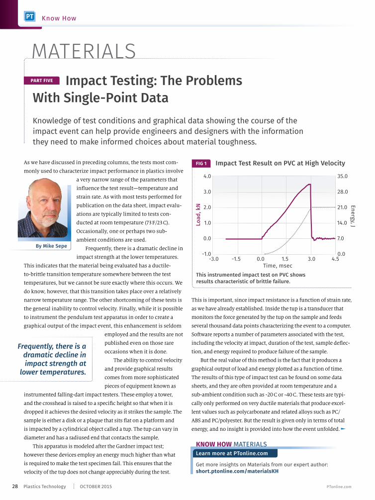
Impact Test Result on PVC at High VelocityFIG 1
This instrumented impact test on PVC shows results characteristic of brittle failure.
Loa
d,
kN E
ne
rgy, J
Time, msec-3.0 -1.5 0.0 1.5 3.0 4.5
4.0
3.0
2.0
1.0
0.0
-1.0
35.0
28.0
21.0
14.0
7.0
0.0
28 OCTOBER 2015Plastics Technology PTonline.com
Know How
MATERIALS
Page 32
longer, a little over 20 millisec as opposed to 3 millisec. But the
most signifcant diference is the change in the failure mode.
The load curve, rather than dropping abruptly after the achieve-
ment of maximum load, tails of gradually and the peak of the load
Figure 1 shows the graph associated with an instrumented
impact test. This test was performed on a PVC material and the
total energy collected at the conclusion of the test is shown
as 21 joules, or approximately 15.4 ft-lb. This is the only infor-
mation that would be provided if the test result were to be
reported on a data sheet. But the curves tell us so much more.
In this case, the load builds up rapidly once the moment of
impact has occurred. Once the maximum value is achieved, the
load declines rapidly and the test is completed in approximately
3 milliseconds. Even visually we can determine that the majority
of the total energy was collected before maximum load was
reached and this behavior characterized what would be consid-
ered a brittle failure. Some materials exhibit an even more brittle
response than this material, and in that case the load curve may
exhibit multiple peaks and some noise as the various layers of
the sample fail in a rapid sequence that produces total energies
as low as 2-3 ft-lb. Sample thickness will obviously infuence the
result, and the total energy can be divided by this thickness to
normalize the results to ft-lb/in., although this is rarely done.
Figure 2 shows an impact test performed on a specimen of
the same PVC material that looks very diferent from the results
shown in Fig. 1. First, the total energy collected is approximately
50% greater at 32.5 joules or 23.9 ft-lb. The test duration is also
This impact test performed on a specimen of the same PVC material shows very different results from those in Fig. 1. First, the total energy collected is approximately 50% greater. The test duration is also longer. But the most signifcant difference is the change in the failure mode from brittle to ductile.
Impact Test Result on PVC at Lower VelocityFIG 2
En
erg
y, J
Time, msec
-10.0 0.0 10.0 20.0 30.0 40.0
4.0
3.0
2.0
1.0
0.0
-1.0
35.0
28.0
21.0
14.0
7.0
0.0
Loa
d,
kN
M ATERIAL S
Know How
The Plastics Drying and Blending Experts
860.627.5110
www.dri-air.com
Press-Side Systems
DRI-AIR offers an extensive
range of multi-hopper drying and
blending systems to maximize
the productivity of your presses
and extruders:
Drying systems with up to 12 hoppers
Blending systems for virgin, regrind, and colorant
Multi-press systems for drying and conveying
DRI-AIR®
... our name
Made in
USA
Page 33
curve is rounded rather than sharp. The energy collected up to
the point of maximum load comprises only about half of the total
energy required to produce complete failure. These features are
characteristics of a ductile response, and the signifcant amount
of energy expended to complete the failure after the point of
maximum load is referred to as energy management. True tough-
ness is captured after maximum load; the energy required to reach
maximum load is more
attributable to rigidity,
not ductility.
So what aspect of
the test conditions
distinguishes the
results shown in Figs. 1
and 2? While a change
in temperature could
certainly account for this, the temperature of both tests was the same.
However, the velocity associated with the test result in Fig. 1 was 15 ft/
sec (4.57 m/sec) while the test result shown in Fig. 2 was obtained at
a velocity of 5 ft/sec (1.52 m/sec). The faster speed produced a result
that would be more typical of a test performed at a lower temperature.
Ironically, it was the data sheet that led us to perform this
experiment in the frst place. The notched Izod impact strength
ABOUT THE AUTHOR Mike Sepe is an independent, global materials and
processing consultant whose company, Michael P. Sepe, LLC, is based
in Sedona, Ariz. He has more than 35 years of experience in the plastics
industry and assists clients with material selection, designing for manu-
facturability, process optimization, troubleshooting, and failure analysis.
Contact: (928) 203-0408 • [email protected] .
A performance problem that had been blamed
on the material actually was due to a change in
the way the molded parts were being assembled.
for this material at 73 F (23 C) is 8 ft-lb/in., a value associated with
a ductile material. However, this supplier had also provided a data
point for 0 F (-18 C). At this lower temperature the result was only
1 ft-lb/in., a value characteristic of a brittle material. The fact that
this material exhibited a ductile-to-brittle transition temperature
somewhere between these two temperatures led us to expect that it
might also display a ductile-to-brittle transition strain rate if we did
not change the temperature. The test result confrmed this and also
helped to solve a performance problem that had been blamed on
the material but actually was due to a change in the way the molded
parts were being assembled.
So as with the properties of strength and modulus we have
again demonstrated the importance of test conditions and the
ability to provide graphical data in order to give engineers and
designers the information they need to make informed choices
about material performance. Next month, we will extend this
discussion to include thermal properties.
MATERIALS
The Plastics Drying and Blending Experts
860.627.5110
www.dri-air.com
Plant-Wide Systems
To further enhance the productivity of dryers and plastic
forming equipment, DRI-AIR offers advanced systems capable
of feeding multiple machines plant-wide including:
Central storage systems
Distribution systems
Conveying systems
Blending systems
Storage systems
Blending systems
Distribution systems
Conveying systems
SAYS IT ALL!
Page 34
Gold Sponsors:
C.W. Brabender Instruments, Inc.
Davis-Standard
Foremost Machine Builders, Inc.
Gala Industries, Inc.
Bronze Sponsors:
ACS Group
Beckhoff Automation
PSI - Polymer Systems, Inc.
Nordson Corporation
Process Control Corporation
Processing Technologies International LLC
Uway Extrusion
Windmoeller & Hoelscher Corp.
The Advanced Team, Inc.
Wittmann Battenfeld
The Extrusion 2015 conference is a frst-of-its kind event
devoted to all aspects of extrusion processing. Developed
by Plastics Technology, this two-day conference will consist
of morning sessions devoted to technical and business issues
common to all types of extrusion, followed by breakout
sessions devoted to specifc types of extrusion.
You’ll leave Extrusion 2015 with the information and contacts your
business needs to increase productivity, cut costs and save time!
Photos courtesy of: Teel Plastics (background); Davis Standard,
Dow Chemical Co., Getty Images/iStockphoto (this page, top to bottom);
Getty Images/iStockphoto, Processing Technologies International LLC.,
Getty Images/iStockphoto (facing page, top to bottom)
Platinum Sponsors:
Presented by:
Extrusion2015
MORNING SESSIONS INCLUDE: MATERIALS • ADDITIVES
HIGH-SPEED PROCESSING • SCREW DESIGN • ENERGY EFFICIENCY
FILTRATION • BLENDING • DRYING • CONVEYING • FOAMING • PURGING
SIMULATION AND MORE!
AFTERNOON TRACKS: FILM/SHEET • COMPOUNDING • PIPE/PROFILE/TUBING
REGISTER TODAY!
ExtrusionConference.com
November 2-3, 2015 Omni Charlotte Hotel | Charlotte, NC
Page 35
REGISTER TODAY!
We look forward to having you join us
at The Extrusion 2015 Conference…
the one and only conference you’ll
need to attend this year.
LEARN!
More than 60 presenters at Extrusion 2015
will give you unprecedented access to
new technology, tips and techniques, and
best practices aimed at helping you boost
effciencies at your operation.
NETWORK!
Make invaluable contacts with the top minds
and innovators in the feld of extrusion as
you network with not only with presenters,
but with the more than 35 suppliers to
the extrusion processing market who are
exhibiting at Extrusion 2015!
If your company is involved in
extrusion—be it film, sheet, pipe,
profile, tubing, or compounding,
or some combination thereof—The
Extrusion 2015 Conference is for you!
!
SCHEDULED
PRESENTERS
ACS Group
Addex
Addivant
American Kuhne
Asaclean
Bohler-Uddeholm
Brampton Engineering
Castle Associates / Dow Chemical
Century Extrusion
Cloeren Incorporated
Compuplast
Conair
Coperion
Coperion K-Tron
CPM Century Extrusion
C.W. Brabender
Davis-Standard
DR Joseph
Dri-Air Industries
Edison Technical Services (Allan Griff)
ENMOUNT Technologies
Entek
Gloucester Engineering
Gneuss
Guill Tool
IQMS
JSW America
Key Filters
Krauss-Maffei Corp.
Kuhne Group
Leistritz
Macro Engineering & Technology
Mucell Extrusion
Nordson EDI
Nordson Xaloy
Novatec
NDC
Pelletron
Piovan
Processing Technologues LLC (PTi)
PSI – Polymer Systems, Inc.
Randcastle Extrusion
Rauwendaal Extrusion Engineering
Reduction Engineering Scheer
Riverdale Global
Siemens
Teel Plastics
TWWomer & Associates
Universal Dynamics
Vecoplan
VAC-U-MAX
Windmoeller & Hoelscher Corp.Extrusion2015
For up-to-date agenda & abstracts, please visit:
ExtrusionConference.com
Schedule and presentations subject to change.
Page 36
There are hundreds of details in the injection molding process and
in evaluating them I can get rather “picky.” This month I’m picking
on the pellets. Regardless of the resin type
or manufacturer, you as a molder want
your pellets to be uniform in size and
shape. But pellets vary in size and shape.
In the case of regrind they can range from
fnes to larger chunks. Bottom line, you
need all the pellets to be uniformly melted
at the proper temperature. If your pellets
range in size and geometry, this won’t
happen. Non-uniformly melted resin will
not yield uniformly good or identical
parts…period. (By pure coincidence, Jim Frankland discusses this
very subject in his Extrusion Know How column this month.)
My guess is that the majority of molders
do not give this issue much thought.
Admittedly, it’s not the frst thing I check
when troubleshooting a problem, but I
need to bump it up a few rungs. We assume
all is well because we see molten polymer
come out of the nozzle when we purge the
machine, or because the parts look OK.
That’s a bad assumption. To understand
the problems with melting non-uniform
pellets, let’s look closer at the melting process.
The melting process starts with the hopper, which feeds the
granules into the feed throat. The hopper should be designed
to provide mass fow—not funnel fow—so that resin is fed
uniformly to the feed throat. There must be no channeling in
the center, which is known as funnel fow (or “rat-holing”). Take
a reality check: Go out to the shop foor and watch the pellets
Why Pellet Size and
Shape Are Important
through the cleanout window. If the pellets up against the window
do not slide down into the feed throat, you have a problem. My bet:
95% of the time, those pellets stay there for the entire run.
So how do you ensure mass fow? Check the hopper angle; for
mass fow: It should be angled 60°. Single-shot hoppers are fne,
provided you do not see fuidizing of the pellets (dancing in an air
stream) when it calls for resin. If fuidizing occurs during screw
rotation, you can guarantee the next shot will be a diferent part,
because the fuidizing keeps some pellets from settling into the
intake screw fights. This is a process variation. If you do have
fuidizing in single-shot hoppers, fx the air leak at the junction
of the feed throat with a good high-temperature silicone gasket.
Once you’ve established mass fow, make sure your feed throat
is clean, unobstructed with big chunks, fnes, or streamers, and is
PID temperature controlled. Erratic water fow in the feed throat
is not acceptable; it’s the most important
zone of the process. It also should be set at
a higher temperature than you think. The
feed throat has two jobs: Feed the resin, and
—just as importantly—act as a vent for gases
escaping from the feed section of the screw.
Set it at 55-65 C (130-150 F) to allow volatiles to
escape and not condense. Even polypropylene
will not get tacky at these temperatures.
If you have bridging problems, note
the composition of the bridged material. If all the individual
granules are stuck, then the feed throat is too hot. But if there is any
completely melted polymer, or if the bridge is a ball of solid plastic,
you do not have a feed-throat temperature problem. More likely
your non-return valve is leaking.
Now let’s turn our attention to the feed section of the screw. As the
screw rotates, it picks up the granules from the feed throat and augers
them through the feed section of the screw. On a general-purpose
screw, the feed section is a whopping 50% of the fight length. The
purpose of the feed section is to compact the pellets and prepare them
for the transition section (also called the compression zone). Here is
where the fights of the screw pick up the granules, and they have to ft
Go out to the shop foor and watch the pellets through the cleanout window. If
they do not slide down into the feed throat, you have a problem.
Uniformity is needed to
help ensure melt quality.
By John Bozzelli
Get more insights on Injection Molding from our expert
authors: short.ptonline.com/moldingKH
Learn more at PTonline.com
KNOW HOW INJECTION MOLDING
Partially Melted Pellets in a Part
Partially MeltedVariation in pellet size and geometry
infuences solid-bed breakup and is the source of partially melted pellets in
your parts.FIG 1
34 OCTOBER 2015Plastics Technology PTonline.com
Know How
INJECTION MOLDING
Page 37
The value-leader in control up-grade solutions, parts and service, CPT offers a full line of robotics and energy saving injection molding machines.
Wetec Automation and Robotics offering end-of-arm tooling and post molding solutions. Also specialize in high speed in-mold labeling.
Asian Plastic servo driven injection molding machines from 55 to 3500 tons. Two Platen, Toggle, Full Hydraulic, and Multi-Component designs available. Serviced by CPT. See how we can help.
Call 513-619-7415 or visit www.cinprotech.com
ABOUT THE AUTHOR: John Bozzelli is the founder of Injection Molding
Solutions (Scientifc Molding) in Midland, Mich., a provider of training and
consulting services to injection molders, including LIMS, and other special-
ties. E-mail [email protected] or visit scientifcmolding.com.
through the feed throat. Somebody will tell
you a story of the feed throat burping pellets
or, worse, being blown to or through the roof.
With compaction comes some pressure,
but the high pressure (thousands of psi)
develops within the transition zone. Here
is where all the melting should happen.
The transition section of the screw is where
the root diameter tapers thicker to the
metering diameter of the screw; this taper
compresses the plastic against the barrel
wall. The ratio of the volume of a feed fight
to the volume of a metering fight is known
as the “compression ratio.”
Here is where the size and geometry of
the pellets become driving factors on how
and when a pellet or granule melts. Any variation in geometry or
size will cause diferent degrees of friction, and this in turn provides
non-uniformity within the polymer melt.
My bet is that variation in pellet size and geometry infuences
so-called “solid-bed breakup, ”a disruption of uniform conversion of the
“solid bed” of compacted pellets into a melt pool within the screw fights,
which is the source of partially melted pellets in your parts (see Fig.
1). My guess is that nearly 70% of your parts have this problem.
Diferent coefcients of friction will generate diferent melting
patterns as the pellets travel down the screw. And when Murphy is feeling
particularly mischievous, you can get completely unmelted granules
in parts. This is a rare occurrence but it does happen (see Fig. 2).
Bottom line: Non-uniformity in pellet size and geometry
fouls up the melting process and is a source of cosmetic, physical,
chemical, and performance problems.
into the fight chamber. Pellets falling into
the fight are no problem, unless they are
either very large or very small (fnes).
If the pellet is so large that it stands
taller than the fight, it may or may not
be sheared between the fight and sharp
edge of the bottom of the feed throat. This
can actually force the screw back, not
allowing the fight to fll completely with
granules. The screw just augers backward
and you do not have a full shot of plastic
in front of the screw. This is common
with small-diameter screws and/or use of
low backpressures. The result is the next
shot has splay, bubbles, shorts, or unmelt.
Fines pose a diferent type of problem,
as they melt much faster and earlier than normal-size pellets, which
in turn reduces the friction needed to melt the normal pellets.
Results are unmelt and black and white specks in your parts.
As the granules move through the feed zone, they begin to pick
up heat of the rear zone, along with some compaction. This is when
your friend Murphy—you remember Murphy’s Law—invites himself
to the party.
First, you have
worry about
where the air
between the
pellets is going
as the pellets
compact. If the melting process starts too early, air gets trapped and
pushed through to the nozzle. The air shows up in your part as splay,
which you may mistake for moisture. Running the feed throat hot
and rear zone at the proper temperature allows the air to escape (vent)
out the feed throat, perhaps taking along some moisture and other
volatiles. Ask around if you don’t believe moisture and volatiles vent
lem
My bet is that variation in pellet size and geometry is the source of
partially or completely unmelted pellets in your parts.
Unmelted Pellet
Variations in pellet size and geometry can cause some materials to pass through the screw completely unmelted.
FIG 2
Completely Unmelted Pellet
in Sprue
@plastechmag 35Plastics Technology
INJEC TION MOLDING
Page 38
a pure solutionA revolutionary new liquid polymeric phosphite stabilizer
· Contains no alkylphenols
· TNPP alternative
Page 39
Introducing Doverphos® LGP-11, a safe,
suitable replacement for TNPP in LLDPE,
HDPE, PP and other polymers to protect
against the effects of oxidative and thermal
degradation while maintaining MI and
low color. Doverphos LGP-11 is a liquid
polymeric phosphite that offers excellent
compatibility in thermoplastic resins,
resulting in reduced additive migration
and exposure, especially for indirect food
contact applications.
Approved
Alkylphenol-free
TNPP alternative
Cost-effi cient
Unmatched color retention
Reduced polymer migration
Reduced processing plate-out
Learn more: Doverchem.com/LGP-11
When it comes to phosphites,
it’s the natural choice
Page 40
EXTRUSION
Why do some polymers having the same melt fow or I.V. (intrinsic
viscosity) sometimes generate diferent specifc outputs on the same
extruder? You may have come across this when changing resin sup-
pliers, and have had to modify established
running conditions as a result. This occurs
particularly in the case of coextrusion, where
close matching of multiple layers is required.
When you are running the extruder at full
speed, yet the net efect is a reduction in
output, that’s a big problem. In fact, even an
increase in output can be an issue if the
extruder is near its torque limit.
Why does this happen? In most cases the
polymer supplier has likely delivered the correct product, but the pellet
geometry may be diferent. Truth is, pellet geometry is often diferent
among suppliers. It may be caused by use of diferent pelletizing equip-
ment or even by a preference on the part of the supplier for a certain
pellet geometry to aid in bulk-handling operations.
Several years ago, I worked with a
polymer supplier that had to make special
pellets just for processors that used
grooved-feed extruders. This supplier
had been furnishing the same pellets for
everyone, but processors running with
grooved-feed sections were getting 20% less output than when they ran
material with the same I.V. from other suppliers.
You can understand why this could happen by knowing the
mechanics of polymer solids feeding. The force that moves material
forward is the drag of the pellets along the barrel inner surface rotating
in relation to the screw. Since only the top layer of pellets contact the
barrel, the movement of the layers farther down in the channel is depen-
dent on the drag from the layers above.
Each succeeding layer has a lower average velocity than the layer
above it due to slip between the layers. If the feed channels get deep
enough, the layers near the screw root may barely move in the down-
channel direction due to the combination of the slip between layers and
the resisting drag of the bottom layer against the screw surface. In View
A of Fig. 1 the pellets are quite layered because of their uniformity. This
is somewhat typical of many “hot-cut” pellets that have a thin, fat wafer
geometry. If the feed material has some random sizing or varying
Pellet Geometry Can Impact Output
Get more insights on Extrusion from our expert authors.
short.ptonline.com/extrudeKH
Learn more at PTonline.com
KNOW HOW EXTRUSION
Pellet geometry is often different
among suppliers.
A simple angle-of-repose experiment can help
you determine how your pellets will feed.
By Jim Frankland
The force that moves the material forward is the drag of the pellets along barrel surface. Only the top layer of pellets contact the barrel, so the movement of the layers beneath depends on drag from the layers above. Highly uniform pellets in View A have a less uniform velocity distribution than with the varying sizes or shapes in View B, so adding some regrind can boost output.
FIG 1 The Mechanics of Solids-Flow Feeding
1
1
2
2
3
3
4
4
5
5
6
6
7
7
VD
VD
VBarrel
VBarrel
View B
Layer VelocityVD1 VD2
VD3
VD4
VD5
VD6
VD7
View A
Layer Velocity
VD1
VD2
VD3
VD4
VD5
VD6
VD7
38 OCTOBER 2015Plastics Technology PTonline.com
Know How
Page 41
EXTRUSION | PRINTING | CONVERTING
Windmoeller & Hoelscher
23 New England Way · Lincoln, Rhode Island 02865-4252
Phone 800-854-8702 · [email protected] · www.whcorp.com
What do you get when teams of brilliant
minds scrutinize each component of
the proven VAREX range to make it
even better? Higher output, superb
ergonomics, improved safety and a
new world of energy effi ciency.
More than just a pretty face: VAREX II.
VAREX II’s modular design provides fl exibility
for producing blown fi lms from diverse resins.
With the new ENERGY MONITORING module,
you get real-time data, making it easier than ever
to identify potential savings. And that’s just the
beginning ...
Page 42
shapes, the layers interact more,
creating a better velocity distribution,
as illustrated in View B. This explains
why a small amount of refeed or other
polymer shapes can increase the
specifc output.
The drag between layers is
determined by the pellet shape,
size, randomness of shape, and the
dynamic friction coefcient between
pellets. The drag of the frst layer
contacting the barrel wall depends
on the friction coefcient between
the pellets and the barrel material,
which may be quite diferent than
the pellet-to-pellet friction coef-
fcient. That pellet-to-barrel friction
coefcient is controlled by heating
the barrel, which causes the pellets to “stick” to the barrel.
This whole area of investigation is related to the science of
tribology. Wikipedia defnes tribology as “the science and engi-
neering of interacting surfaces in relative motion.” There are
no hard and fast rules for evaluating a polymer’s tendency to
feed, because the criteria noted—shape, size, and randomness—
interact, and frictional force depends on contact area even though
the friction coefcient remains essentially the same for given
polymers. A simple test that gives insight into conveying char-
acteristics of your polymers is called the “angle of repose,” and
it basically measures the way the polymer piles up when gently
poured onto a fat surface (see Fig. 2).
All the criteria mentioned about the pellet characteristics are
ABOUT THE AUTHOR: Jim Frankland is a mechanical engineer who has
been involved in all types of extrusion processing for more than 40 years.
He is now president of Frankland Plastics Consulting, LLC. Contact
[email protected] or (724)651-9196.
involved in this measurement, so it’s
hard to distinguish which of the criteria
dominate the resultant angle of repose:
Size, shape, randomness, and friction all
play a part. However, for a given polymer,
the higher the angle, the better the
solids-conveying efciency in smooth-
bore extruders. This rule of thumb also
applies to grooved-barrel extruders, but
the particle size and shape relative to how
they ft in the grooves is actually more
critical to their solids-feeding efciency.
It should be noted that a higher angle
of repose can occasionally have a negative
efect on overall feeding efciency, as
polymer may not fow as freely into the
screw. The angle of repose is not a solids-
fow measurement necessarily, but gener-
ally the higher the angle of repose, the poorer the solids fow is in
areas upstream of the screw that depend on gravity—such as hoppers,
feed tubes, and magnet packs. This issue seldom comes into play
except when there is some restriction to entry into the screw, such as a
blocking apparatus over the feed opening, a small feed opening, or no
column pressure due to bridging or a ledge above the screw.
Trying the simple angle-of-repose measurement on your
polymers may answer some questions about specifc output for
polymers of the same type but diferent manufacturers.
FIG 2
The Angle of Repose Test
This simple test measures the way the polymer piles up when gently poured onto a fat surface. It can be useful to answer some questions about specifc output for polymers of the same type but different suppliers.
Angle of Repose
CHOOSE THE NUMBER ONE.
Efficiency at the fore.
as with the new INTAREMA®. Counter Current
makes it possible. Because the extruder
handles more material in a shorter time.
oughput
e range.
For more pr , and process
.
EREMA North America, Inc. / 23B Old Right Road
Ipswich, MA 01938 / (978)356-3771
www.erema.net
40 OCTOBER 2015Plastics Technology PTonline.com
Know How
Page 43
How the “Internet of Things” Optimizes Productivity and Decreases DowntimeToday, full scale online diagnostics and remote service allows equipment
suppliers to help molders:
• Reduce down time during troubleshooting
• Increase productivity
• Increase part quality
• Identify defective machine parts before technicians arrive
• Monitor machines remotely, and tune machine parameters (service
values) to keep equipment running until service arrives with parts
Industry 4.0, the “Internet of Things” and similar technologies take this to
another level. They allow the IMM to “talk” to the peripheral equipment
and ideally, allow them to be serviced remotely through the IMM. Through
live demonstrations we will show that all the above is already reality.
PRIMARY TOPICS: > Remote technical service on injection molding equipment > Remote process support on IMMs > Industry 4.0 (intelligent connection of IMMs with peripheral equipment)
Tuesday, October 27th 2:00 PM EST
Register for this webinar at: short.gardnerweb.com/wb
Christian started his career with Wittmann
Battenfeld at the Tech Center in Kottingbrunn,
Austria in 1985. After 5 years as a process
engineer and 25 years doing customer training
for Injection Molding Machines in Austria, he has
recently relocated to our USA Headquarters, in
Torrington, CT, where he manages the Tech
Center and molding machine training.
Markus Klaus is Divisional Manager of Injection
Molding Machines for Wittmann Battenfeld, Inc.,
Torrington, CT. He earned a mechanical
engineering degree from the College of Darmstadt
(Germany). He has worked in the plastic industry
for almost 20 years (Wittmann Germany,
Ferromatik Milacron Germany, Toyo Germany) and
joined Wittmann Battenfeld in the USA in 2013.
PRESENTER
Christian Glueck
Technical Trainer/ Tech Center Manager, Injection Molding Machines
Markus Klaus
USA Division Manager Injection Molding Machines
WEBINAR a feature of PTonline.com
Page 44
Lifters are critical components that impact tool maintenance, repair,
and injection molding. There is a lot to discuss about lifters: design
considerations, materials used, wear sur-
faces; buddy/helper pins, defection, shape
(round vs. square), part-sticking issues,
ftting/spotting, and timing/preload. In this
column I will discuss the lifter, why it is
used, angles/travel, and some design con-
siderations in relation to the angle/travel.
I manage thousands of preventive-
maintenance activities and repairs a year.
These involve a wide variety of mold
designs from all over the world, running
various materials. In the process I have
acquired a lot of knowledge with respect
to tool designs and how they can impact
the manufacturing environment with
failures and processing issues. I use the
term “red fags and sirens” when I want to
label something as a concern. And if there
is one component that jumps out more
than others with respect to tool mainte-
nance and repairs, it’s the lifter.
When it comes to tool design, most
people on the tool-maintenance side
prefer slides, if possible. But in cases
where lifters are used, slides are usually
not an option. I mention this because
there have been cases where slides could
have been used instead of lifters in a few
situations I have encountered.
A lifter is a component that travels
with the ejection stroke and moves on
an angle to slide/pull cavity steel away
from undercuts or details not in die draw
where slides or other mechanics are not
an option. There are other names for
this component, as well as design varia-
tions. The design, angle, and materials
used for lifters can have a big impact on
tool performance over years of opera-
Having Trouble with Lifters?
tion. I have had many tools run fawlessly with zero lifter issues
over millions of cycles. But with other tools I have had nightmares
caused by lifters. So the lifter stands out as one component in a
mold design that needs a little extra attention.
Some of you may be thinking you have no issues with lifters,
but my guess is you are running parts with “lessons learned,” using
low-draft lifters with shallow undercuts. In my arena, I am involved
with numerous styles of parts and plastic materials across many
industries, so we run into some challenging issues with lifters.
LIFTER ANGLE & TRAVEL
It’s fairly simple math to fgure out the angle at which the lifter
must move. All you need to know is the depth of the undercut on
the part and the ejector stroke being used (or
available) with the tool or machine. If, for
example, your detail or undercut is 0.5 in.
deep, your lifter would need to travel this
amount plus clearance so the part will remove
freely from the mold without hangups. The
amount of clearance needed varies on the size
of the part, plastic being used, and shrinkage.
I have seen situations where the clearance
was indeed part of the design, but because of
part shrinkage the lifters were still engaged,
making part-removal very difcult. For example,
if you had a PP part 20 in. long, you could have
part shrinkage of up to 0.4 in. I stress this
because it is sometimes overlooked.
In the example above of the 0.5-in.
undercut, if we are going to design a 0.1-in.
clearance, our lifter travel would need to
be 0.6 in. Let’s also assume we have 4 in.
of ejector stroke. I use trigonometry when
calculating this, but there is a less complex
method: 1 degree will travel approximately
Lifters can cause tool maintenance, repair, and processing issues if not
designed properly. Here we begin a series on how to avoid all this.
Get more insights on tooling from
our expert authors:
short.ptonline.com/toolingKH
Learn more at PTonline.com
KNOW HOW TOOLING
By Randy Kerkstra
PART 1 OF 2
FIG 1
Critical elements of tool design with lifters are the lifter angle, travel, and supported/unsupported length.
42 OCTOBER 2015Plastics Technology PTonline.com
Know How
TOOLING
Page 45
ABOUT THE AUTHOR: Randy Kerkstra has been in the plastics industry for more than 26 years,
occupied frequently with troubleshooting injection molding. He is currently a tooling manager for a
large, multi-plant molding and manufacturing company. Contact: [email protected] .
0.017 in. over 1 in. So over 4 in., 1° will travel 0.068 in. We
need 0.625 in. over 4 in., so just multiply 0.068 by any
number to fgure out the angle for our lifter. In this case,
we would put the lifter at 9° (9 x 0.068 = 0.612 in. travel).
Now that we understand how angles are determined for
lifters, let’s discuss how these angles can impact mainte-
nance. From a mechanical viewpoint, the greater the angle,
the more concern about mechanical forces contributing to
wear and failures. The unsupported length is just as much
a concern as the angle. You could have a steep-angled lifter
more robust than a shallow-angle lifter with too much
unsupported length. This comes down to the unsupported
length/diameter ratio along with the angle of the lifter.
For lifters on steeper angles, you can add a “buddy” or
“helper” guide pin to the lifter slide to prevent defection
and keep the slide traveling in the proper position (see Fig.
2). These helper pins are
a great option and drasti-
cally reduce lifter failures
and wear on the rod or
shank. I typically would
start with at least a 10°
angle when considering
using a helper pin. But
remember that a low-
angle lifter with excessive unsupported length could have
defection issues.
In one case, we were having problems with fash under
the lifter and with the lifter standing above the cavity
surface. This lifter had a 0.5-in.-diam. rod at 3° but had
excessive unsupported length. The lifter slide in the ejector
plates would not make it all the way home, as the lifter rod
was not robust enough and defected because of the exces-
sive unsupported length. When this happened, the lifter
head would not seat all the way and would stand above
the cavity surface, causing fash underneath.
There is really no concrete standard to determine when to use helper pins. I use 10° as a
reference point, but some lifters with angles under 10° may need them also. And some lifters
with angles greater than 10° may not need them.
During tool design, when you determine the lifter angle based on stroke, you need
to make sure the unsupported length does not exceed the travel. I have seen many cases
where the back plate or mold base is cleared by the lifter rod/shank and the bearing
surface is only on the cavity. You should always have a bushing or guide blocks on the
back plate or mold base to give the lifter as much support as possible. Lifters can also
defect as a result of cavity pressure, causing read-through on the part. In cases where
there is no shutof shelf on the lifter, cavity pressure can push it below the cavity surface.
Next month, I will get into more specifcs on lifters in wear surfaces, materials used,
ftting, timing, and more.
The greater the lifter angle, the
more concern about mechanical forces
contributing to wear and failures.
10.00°
10.00°
Lifter Pin
Buddy/Helper Pin
A “buddy” or “helper” pin can help prevent
defection of lifters set at steep angles,
minimizing wear and chances of failure.
FIG 2
@plastechmag 43Plastics Technology
TOOLING
Page 46
• Upgraded Siemens PLC with 7” High-Def Display
• Displays Drying Faults and Uses Pictorial Solution Screens
• Automatically Detects and Avoids Over-Drying
• Smart Ethernet Connection with Data Logging
• Available in 25, 50, 75, 100, 150, 200 lbs./hr
All built-in. Only from NOVATEC. Starting at $13,250
www.novatec.com/dryers
Very Smart
Upgraded Software
Senses Faults…
Pictorially Guides
You in a Solution
Just Enter Your
Polymer Type and the
Smart Control PLC
Does the Rest…
Standard EZ Push Handles
Automatically Tells You
When to Change Filters
Standard Conveying
Blower Package
Standard Vacuum
Purge Valve
Built-in Standards...
Sold as Options Everywhere Else!
© Copyright 2015 NOVATEC, Inc.
Easiest to Use Mo
Page 47
Standard 5-Year Warranty | Made in the USA
800-237-8379 | www.novatec.com
Standard LED Alarm Light...
Matsui Charges Over $250!
Upgraded Siemens PLC
with 7” Hi-Def Screen
What Good is a Mobile Dryer if
You Don’t Know the Dewpoint?
We Include It. Matsui
Charges an Extra $900!
Standard Data Logging
Ethernet Ready
Exclusive Overdry Protection
Ideal for Nylon and Other
Sensitive Materials
Lifetime Desiccant
Wheel Warranty
Minimizes Energy Consumption
by Continuously Adjusting
Heater and Air Temperatures
Standard Dry Air Conveying Package
Standard Insulated Hopper Automatically
Adjusts Air Temperature Based on Monitoring
to Regulate Temperature in Hopper
bile Wheel Dryers
Page 48
Toolmaker and thermoformer takes concepts to production-ready parts in record time.
R&D Thermoformer:
Tek Pak Is Launch Pad
For New Products
When resin maker Eastman Chemical Co., Kingsport, Tenn., and sheet extruder Pacur in Oshkosh, Wis.,
wanted a thermoformed demonstration part to show of a new three-layer, foam-core PETG sheet, they
knew where to go.
“We don’t have a lot of competition, because hardly anyone one else does what we do,” declares Tony
Beyer, president and founder of Tek Pak, Inc., in Batavia, Ill. (tekpak.com). “We are willing and able to
go after new-product development applications, while most big thermoformers want to get in after that
stage of the project cycle, when it’s time to make hundreds of thousands of parts. We’ll make tens of
parts, if that’s what’s needed.
The largest machine at Tek Pak is this Kiefel KMD 60 B inline pressure former, used for mid-volume production as a “bridge” between prototyping and full production—which usually is performed by another thermoformer.
46 OCTOBER 2015Plastics Technology PTonline.com
By Matthew H. Naitove
Executive Editor
On-Site Tek Pak, Inc. • Batavia, Ill.
Page 49
“That’s why Eastman (eastman.com) and Pacur (pacur.com) came
to us when they wanted someone to design a mold that would
really challenge Eastman’s new Eastalite material, extruded into
sheet by Pacur. When people see the part we
designed (photo on next page), they’ll know
that material has good formability.” Seeing
interesting potential in the new tri-layer
sheet, Tek Pak itself prototyped a medical
tray to protect sensitive equipment.
NOT YOUR TYPICAL THERMOFORMER
Beyer’s path to becoming a specialty thermoformer started in the
early 1970s as a toolmaker at Plastoflm Industries, Wheaton, Ill.,
leading custom thermoformer. In those days, Plastoflm had 550
people in fve locations and was a pioneer in medical thermo-
forming. Beyer rose to plant manager of the home facility, which
had 400 employees. After the original owner
retired and the frm was sold and resold
three times in fve years, Beyer left and
started Tek Pak in 1992.
His initial focus was on carrier tapes that
held components for automated assembly
of cellphones. That application started
at Plastoflm in 1981, Beyer says, “but the
fnance people there said it would never
amount to much.” How wrong they were.
Carrier-tape business at Beyer’s new frm
grew 50% a year for seven years in a row
during the 1990s, with Motorola as the
leading customer. Tek Pak even opened a
plant in Sweden to make carrier tapes for
cellphone maker Ericsson in the late ’90s.
Then China happened. “It all changed
a lot faster than anyone thought possible,”
recalls Beyer. In around 2000, 40% of his
business moved to China in just six months.
He closed the Swedish plant, which is now
a sales office. “We went into survival mode
and refocused on standard thermoforming,
tooling, and prototyping.”
Today, Tek Pak has a main ofce and
production plant in Batavia with 27,000 ft2, 70 people, fve extru-
sion lines for carrier tapes, and 40 thermoforming machines, 35
of them for carrier tape. In addition, Tek Pak also has a 12,000 ft2
R&D center 3 miles away in St. Charles, Ill., which houses seven
small machines. That separate R&D facility, with a dedicated
staf of 15, is part of what distinguishes Tek Pak from the vast
majority of thermoformers.
“We work for startup companies and for Fortune 500’s,” says
Beyer. “They have an idea and need someone to help them get
it started. Many projects come in as concepts, not full-blown
designs.” He cites the example of a surgical tray kit, for which
Tek Pak was given only the parts the kit had to contain and a
general layout scheme. “They ask, ‘Can
you make this?’ For the answer, we rely
on our tool kit—our knowledge of tooling
and of uncommon materials and how
to form, cut, punch, and weld them. A
Fortune 500 company came to us after
working on a new project for 16 weeks
without success. In two months, we had
working samples for them.”
This sort of development work can take a lot of itera-
tions. “Medical development can take 18 months of trials and
sometimes up to 16 or more revisions,” says Beyer. “We got into
this business because no one else wanted to mess with proto-
typing—too much detail, too little volume. We do 50 prototypes
a month—nobody else even comes close to that.”
This approach has paid of for Tek Pak. Says Beyer, “We’re not
caught up in commoditization. Most customers realize there’s a
cost associated with what we do.” Tek Pak’s biggest market is
“We got into this business because no one else wanted to mess with
prototyping—too much detail, too little volume.”
Visit the Thermoforming Zone.
Learn more at PTonline.com
QUESTIONS ABOUT THERMOFORMING?
Tek Pak builds a lot of its own forming systems for single-cavity prototyping. Scott Carter, v.p. of R&D stands next to one such system.
@plastechmag 47Plastics Technology
On-SiteTek Pak, Inc.
Page 50
electronics, followed by medical and food packaging, as well as
some retail packaging. General thermoforming is only about 20%
of its $13 million annual business.
One medical application prototyped
by Tek Pak just received FDA approval
after passing a range of tests. It’s a PETG
tray package for an implantable heart
pump worth upwards of $100,000.
Durability and impact protection of the
contents were critical considerations,
Beyer points out.
Tek Pak typically helps
a customer optimize a
product design to ensure
its manufacturability, then builds prototype
tooling and forms initial samples. Beyer explains,
“We usually start with a single-cavity prototype
tool, but it’s built just like a production tool and
is suitable for mid- or long-range, low-volume
production.” For some customers, Tek Pak also
provides initial or “bridge” production to support
market development or allow time for a customer
to ramp up to full-scale volumes.
One resource for bridge production is Tek
Pak’s largest continuous former, a Kiefel KDM
60 B pressure former with mold area of 460 x
600 mm (about 18 x 24 in.). On a recent day, the
machine was running a blister package for a
consumer electronic device using recycled PET
(RPET). The blister was running 3-up at 1000
shots/hr. The order called for 60,000 parts over
three months.
Medical development
can take 18 months of trials and
sometimes up to 16 or more
revisions.
After development and perhaps initial production, Tek Pak
usually hands of the job to another thermoformer for full-scale
production. “We typically run 10,000 to 100,000 parts. But we
have made millions of some specialty parts, like carrier tapes or
difcult parts that others won’t run.
“Telescoping time is our business,” adds Beyer. “Lead time for
a design change in carrier tapes is generally three days or less.
A food package for Wal-Mart took us three weeks for develop-
ment and we had products for them in four weeks.” Tek Pak’s
speed record is 4 hr to design and build a mold and run sample
parts. For its demanding clientele, Tek Pak has to be fast. “We’re
Carter, a Ph.D. chemical engineer, has at his disposal an analytical lab with an FTIR spectrometer (right) and Dynamic Mechanical Analyzer (left), neither of which would be found at the vast majority of thermoformers.
Tek Pak created this demo part to show off the easy formability of Pacur’s new PETG Foam sheet made with Eastman’s Eastalite. (Photo: Eastman)
Beyer, who started out as a toolmaker himself, says, “I want to push the limits of what our tooling people think they can do. We live by accomplishing new things, so we have to take risks.”
48 OCTOBER 2015Plastics Technology PTonline.com
Tek Pak, Inc.On-Site
Page 51
working on 30 prototypes this month—
and it’s a slow month,” exclaims Beyer.
R&D TOOL KIT
The “toolkit” that makes this possible
includes knowledge of a broad range of
materials, including less common resins like PEEK, Ultem PEI,
PVDF, TPU, specially formulated conductive/antistatic com-
pounds, and even metalized flms. Notes Scott Carter, v.p. of R&D,
“Around 30% of our materials are multilayer combinations, which
aren’t in any property database.” He cites the example of a PE/
nylon/PE flm for a medical containment bladder. The nylon layer
adds stifness and puncture resistance.
Another example is the three-layer
solid/foam/solid sheet developed by Pacur
using PETG skins over Eastman’s Eastalite
copolyester foam core. It’s a styrene-free
alternative to HIPS with faster cycles,
greater resilience, lighter weight, more
durable living hinges, and excellent cush-
ioning ability. Beyer sees a range of appli-
cations potential in protective packaging
for medical devices and fragile electronics,
and even some consumer packaging. (See
August Close-Up for more on Eastalite
foam-core sheet.)
Carter, a Ph.D. in chemical engi-
neering, has an analytical lab the likes
of which you won’t see at many thermo-
formers. It includes a ThermoScientifc
FTIR spectrometer, used to identify
unknown materials that customers send
in and to validate that incoming materials
are what they are supposed to be. There’s
also a dynamic mechanical analyzer (DMA) from TA Instruments,
with which Tek Pak can measure the glass-transition temperature
(Tg) of unfamiliar materials and determine the optimal preheat
and forming temperatures. One current task for the lab is analyzing
10 diferent varieties of mineral-flled PP sent in by a customer to
produce samples of cofee-cup lids that would replace PS.
When it comes to detailed design of new products and molds,
Tek Pak utilizes two diferent 3D CAD packages and 2D AutoCAD
software. While that’s twice as many 3D CAD programs as most
thermoformers use, “It means we can accept more native CAD
fles from customers—depending on what they use in-house—
and that means higher accuracy in translating their geometry,”
explains design engineer Kevin Swanson.
Another tool in Tek Pak’s kit is its equipment, much of it
homemade. “We have adapted commercial machines for proto-
typing and low-volume work,” says Carter, “and we have built our
own small-footprint R&D machines with
up to 4 x 6 in. forming area and radiant heat
top and bottom.” These roll-fed, continuous
forming machines are equipped with
“gripper chains”—conveying chains with
fnger grippers—developed by Tek Pak for
thck materials, like 40-mil ABS, and fexible polyolefns as thin as 2
mil, that can’t be handled efectively with conventional pin chains.
These R&D machines are designed for small, 1-up prototypes.
“Some customers think we should start prototyping with a 12- or
16-up tool,” observes Beyer. “But that just multiplies the difcul-
ties and burns up more time, money, and material in learning to
get it right. We start out to make one good part consistently, then
scale it up. And some particularly difcult parts have to run 1-up
in production, too.”
Another special piece of technology is laser trimming, performed
by a pair of LaserSharp LPM Flex 400 machines from LasX Industries,
White Bear Lake, Minn. (lasx.com). “These are great for R&D because
we don’t have to wait for trim dies to be built,” enthuses Beyer.
“Instead of spending $12,000 for a matched-metal punch, the laser
can cut a part in 0.5 sec.” On some special electronic parts, the laser
cuts patterns of up to 400 tiny holes (1.2 x 0.6 mm) in about 4 sec.
Besides prototypes, Tek Pak manufacturers inserts for Corvette
hood “badges.” Formerly injection molded, the inserts are thermo-
formed and laser trimmed at volumes of around 65,000 annually.
Beyer notes that laser trimming is used by some other thermo-
formers, mainly on some heavy-gauge automotive jobs, but those
are not high-speed models like Tek Pak’s.
“We have the largest toolroom in the therm-forming industry that nobody knows about.”
With a dozen people and an equal number of CNC machines, Tek Pak’s 6000 ft2 toolroom is “the largest in the thermoforming industry that nobody knows about.”
@plastechmag 49Plastics Technology
On-SiteTek Pak, Inc.
Page 52
TOOLING SPECIALIST
Tek Pak builds all its own tools, and also many for other thermo-
formers, even for some heavy-gauge jobs. It also machines its
plug assists from thermoset syntactic foam. Beyer is understand-
ably proud of his 6000 ft2 toolroom with a staf of 12 and a dozen
CNC machines with up to 40 x 60 x 15 in. working area. He calls
it “the largest toolroom in the thermforming industry that
nobody knows about.”
Most of the molds are aluminum—“It can do millions of
shots,” according to Beyer, who believes steel is nearly obsolete
for most thermoforming applications. Most of Tek Pak’s work
uses cavity inserts that ft into standard mold bases.
The toolroom has built 10,000 molds for carrier tapes alone,
with six to 12 cavities. “We make 30 to 40 tools a month,” says
toolmaker Rick Spera. “Our record is 86 carrier-tape molds in
one month.”
“We have 250 man-years of experience
in our toolroom staf,” says Beyer. “But
I want to push the limits of what our
tooling people think they can do. We
live by accomplishing new things, so
we have to take risks. For example, we
frequently violate the rules on draw
ratios in carrier-tape tools.” He adds,
with a sense of irony, “We constantly try
out things that don’t work!”
SPECIALIZED PRODUCTION
Clearly, a lot of things do work for Tek
Pak. Besides its focus on prototyping,
the frm has also developed a couple of
specialties in commercial production.
One that has already been mentioned is
carrier tapes for automated electronic
assembly. Wound on reels, these tapes
are formed with tiny pockets—as small
as 0.1 x 0.15 x 0.1 mm—to hold compo-
nents that race through assembly sta-
tions at speeds up to 75,000 cycles/hr.
Some of Tek Pak’s carrier tapes are extruded directly over a rotary forming wheel.
Laser trimming is well suited to development work because it requires no tooling and is fast—for example, punching up to 400 small holes in about 4 sec. Tek Pak thermoforms and laser trims inserts for the Corvette hood badge.
50 OCTOBER 2015Plastics Technology PTonline.com
Tek Pak, Inc.On-Site
Page 53
As a result, tight tolerances of ± 0.1 mm or less are
standard, says Tracy Wolf, director of sales and business
development. Accounting for half of Tek Pak’s business, the
35 carrier-tape forming
lines at the Batavia plant
constitute the largest
production facility for this
product in North America,
according to Beyer. (He
says the largest plant in
Asia has over 600 lines.)
The tapes are extruded
on-site from fve small
extrusion lines with fat
dies up to 8 in. wide. Typical materials are conductive HIPS
0.3-0.4 mm thick or 40-mil conductive ABS. These specialized
antistatic compounds are not available from standard sheet
producers, so Tek Pak has to work directly with compounders.
It also sells some sheet to electronic OEMs that do their
carrier-tape forming.
Some of the sheet is slit into narrower tapes and wound on
reels for subsequent thermoforming. Some is extruded, formed,
and punched inline. In the latter cases, the hot sheet passes
around a rotary forming mold and then is slit in two. Deionized air
is blown over the tape to remove particulates, which are trapped in
a receptacle underneath.
Design engineer Kevin Swanson showing a CAD model for the cellphone package on the desk in front of him. Tek Pak uses two 3D CAD programs as well as 2D AutoCAD.
“I want to push the limits of what our
tooling people think they can do. We live
by accomplishing new things, so we
have to take risks.
By integrating Mac Process and Schenck AccuRate, the Schenck
Process group offers proven bulk material handling systems to plastics
manufacturers for pneumatic conveying, fi ltration, weighing and
feeding from one unifi ed source. Products and services include:
• Feeders • Airlocks and Valves
• Weighbelts • Process Controls
• Dust Collectors • Engineered Systems
• Turnkey Solutions • Product Testing
Let us help you put a complete system together for your plastics
manufacturing process. Contact us for more details or to
request a quote.
Combining the technologies of Mac Process and Schenck AccuRate
Complete Material Handling Solutionsfor Plastics Processing
Schenck Process
7901 NW 107th Terrace
Kansas City, MO 64153
888-657-3098
[email protected]
www.schenckprocess.com
@plastechmag 51Plastics Technology
On-SiteTek Pak, Inc.
Page 54
540.884.2589gala-industries.com
Because of frequent product
changes, quick mold changes are vital
in the carrier-tape business, typically
taking 30 min, though sometimes as
little as 5 min if there is no material
change. According to Beyer, quick
changes are also “becoming more
critical in general thermoforming as
we grow the business.”
A second specialty, of much newer
vintage, is being developed at Tek Pak.
Production forming (not just proto-
typing) of very thin, fexible materials,
such as LDPE or EVA at 2-3 mils up to
20 mils, has promising potential for
diaphragms, containment bladders,
and gaskets for medical and electronic
applications. An example is a domed
diaphragm 4-6 mils thick ± 2 mils. “We’re
doing it because most people don’t want
to do it,” says Beyer. “Standard equip-
ment can’t handle it. That’s why we built
our own with fnger grippers instead of
pin chains, which won’t hold these mate-
rials.” He adds, “Most of these projects
start out very small—no truckload orders
in six months.”
A new specialty is forming very thin,
fexible materials. “We’re doing it because most
people don’t want to do it. Standard equipment
can’t handle it.”
One specialty of Tek Pak’s is carrier tapes for electronic assembly, an example of which is shown here, made of 0.3-0.4 mil antitstatic HIPS. With fve small tape extrusion lines and 35 forming machines, Tek Pak reportedly has the largest carrier-tape plant in North America.
52 OCTOBER 2015Plastics Technology PTonline.com
Tek Pak, Inc.On-Site
Page 55
FLEXIBLE, HYGIENIC & PORTABLE.
5370 GUY YOUNG ROAD
BREWERTON, NY 13029
P: 315.676.3035 | F: 315.676.2875
[email protected]
WWW.SCHNEIDERPA AGING.COM
No matter the shape of your bottle,
we have the tools to pick it, pack it
and palletize it without the touch
of a human hand. The Schneider
bottle packing solution keeps your
line more hygienic while giving you
unparalleled fexibility. Designed to
be easily moved with a forklift to
another line or another facility, it
gives a whole new meaning to
the word “adaptable.”
Beyer sees opportunities for thin
fexibles in markets that don’t exist yet.
For instance, he envisions that such
materials in medical applications could
reduce hospitals’ disposal costs for
hazardous or infectious “red-bag waste”
by making the waste less bulky and
more compressible.
‘GAME CHANGER’ AHEAD
Tek Pak has carved out another niche for
itself, by riding the leading edge of what
Beyer sees as a new wave about to wash
over the medical thermoforming busi-
ness. “It’s a game-changer that’s just
happening now and is gaining
momentum. Medical-device OEMs want
to do their own thermoforming in-house
to save freight.” Examples are packaged
surgical kits, for which the OEM ulti-
mately may want to make the devices
and package them in the same facility.
Since few medical OEMs have much
experience in thermoforming, Tek Pak
has developed a role as a consultant and a
supplier of turnkey forming systems. The
Kiefel machine, because of its mid-range
production capacity, is a good tool for
developing a turnkey package.
“It has already happened in carrier tape
for the past decade around the world,” says
Beyer. “We have supplied 15 or 16 carrier-tape
systems with our own specialized machines.
There’s no standard catalog for that.”
When a “game-change” like this
threatens to strike your market, Beyer
says, a manufacturer has to ask some vital
questions: “How do you position yourself
for that change? When do you invest to
survive and proft from that change? And
how long is the ‘on ramp’ before you can
get cash out of it?”
‘Game-change’: Medical-device OEMs want to do their own thermoforming in-house to save freight.
This LDPE tray is an example of a new specialty niche in thermoforming very thin, fexible materials. The 0.015-in.-thick tray was designed to test the limits of the material and process.
@plastechmag 53Plastics Technology
On-SiteTek Pak, Inc.
Page 56
The dynamics of the stretch flm market are continuously
evolving. Worldwide, the big trends and drivers in cast stretch are:
• Downgauging:
The average gauge
of hand wrap has
gone from 25 microns to 10 microns (µ) and the average gauge for
machine wrap and power pre-stretch has gone from 35µ to 15µ.
Cast-flm lines are being engineered to allow production of thinner
flms at higher-than-ever winding speeds (up to 2300 ft/min or 700
m/min). More fexible inline winding has been developed to reduce
labor costs and scrap rates.
• Higher stretch percent:
The upper end of the
stretch range has risen
from 200% to 300%.
• Increased use of
machine wrap by end
users: The trend is moving
from hand wrap to machine wrap—a result of increasing labor costs.
• Higher machine wrapping speed among end users: Average
wrapping speed has moved from 25 rpm to 60 rpm (the latter
applies only to orbital/rotary arm-wrapping machines).
• More layers: The movement towards multilayer flms con-
tinues to grow and diversify. Film confgurations range from
three layers all the way up to dozens of nanolayers. Nanolayer
structures give the flm a “plywood” efect that enhances
mechanical properties such as puncture and tear resistance and
allows thinner pure-metallocene PE layers.
In Europe, nanolayer technology is growing quickly. Progressive
processors include the likes of Apeldoorn Flexible Packaging B.V.
(AFP), a Dutch producer of a wide range of blown and cast flms for
packaging, which has been utilizing nanolayer technology since
January 2009. AFP’s original nanolayer launch was for 27-layer
flms, but Eddy Hilbrink, who heads up strategic R&D projects,
told Plastics Technology of plans to push the envelope further with
the installation of a third nanolayer line, this one for more than 50
layers (see May Close-Up).
Among North American processors, no one seems willing to
even discuss numbers of layers. A 2012 patent lawsuit probably
explains why. In February of that year, a technology licensing frm
called Multilayer Stretch Film Holdings fled separate lawsuits
against nine leading North American stretch-flm processors,
claiming they had violated a patent covering stretch cling flms
with seven or more layers. Industry sources report that most of the
processors named have since settled out of court. Last November,
however, the Federal District Court in Memphis ruled in favor of
stretch-flm processor Berry Plastics, Evansville, Ind. Multilayer
Stretch Film Holdings has appealed that ruling. Berry (berryplastics.
com) would not comment on the matter.
Nonetheless, signs suggest that more processors in North
America are moving beyond the fve-layer structures that have been
generally considered “state of the art” in the NAFTA region since
By Trudy Iaccino, ExxonMobil Chemical Co.
Peter F. Cloeren, Cloeren Incorporated
Dr. Frank Hoffmann, Windmoeller & Hoelscher
The industry did not jump from fve-layer
flms to 55 layers in one fell swoop. It took two
decades to arrive there.
Nanolayer feedblock and die package from Cloeren. Nanolayer feedblocks are considerably
larger than conventional coex blocks. For dies, fow-channel shapes had to be reexamined,
and precision of tolerances had to be tightened up, in order to meet the process demands
associated with such thin layers.
Here’s What You Need to Know to Make World-Class Stretch Film
Advances in materials, feedblock/
die technologies, and winding can
help processors develop more
sophisticated cast-stretch products.
54 OCTOBER 2015Plastics Technology PTonline.com
Tips and Techniques
Page 57
Peter Cloeren launched Chaparral Films in Orange, Tex., in 1994. In
August, Sigma Stretch Film, Lyndhurst, N.J., the largest producer
of stretch flm in North America, announced that it would be
installing a nine-layer cast-stretch line from SML of Austria (U.S.
ofce in Gloucester, Mass.; sml.at) with a Cloeren die/feedblock
package. The line, which is expected to be delivered by the frst
half of next year, will be used to run 20-in.-wide rolls nine up.
Another major processor, Inteplast Group’s AmTopp Stretch Film
Div. (inteplast.com), also announced a major expansion recently
(see sidebar). Market consultant Mastio & Co., St. Joseph, Mo.
(mastio.com), projects stretch flm will grow at 4.5%/yr through
2017, when it will consume more than 2.2 billion lb of PE.
How does a processor serving this market kick it up a notch
from a technology standpoint? While stretch lines are large and
complex, three keys to developing world-class stretch flm are
materials, feedblocks/dies; and winding. In this article, industry
leaders in each of these areas—ExxonMobil, Cloeren, and
Windmoeller & Hoelscher, respectively—share their expertise.
IT STARTS WITH MATERIALS
In trials with customers and leading machinery suppliers,
ExxonMobil has found that certain of its resins ofer desirable
properties for stretch flm:
• Enable metallocene-based PE (mPE) resin provides high holding
force at low flm thickness.
• Exceed mPE resin provides high holding force and puncture
resistance at high stretch ratios.
• Vistamaxx performance polymers are propylene-based elasto-
mers that provide high tear-propagation resistance at high
stretch ratios. These resins
are also commonly used to
provide reliable, cost-
efective cling in these
multilayer flms.
Enable mPEs are
branched metallo-
cene resins. This metallocene resin family has higher shear
thinning, which allows for low-melt-index grades to be used
in cast-flm extrusion to obtain improved physical properties.
The strain-hardening curve illustrates that these resins have
a distinct second yield point, which provides a step change in
tensile strength. Using these resins in cast stretch flms yields
high tenacity and high holding force across a wide stretch
range, which delivers additional value in cast hand-wrap and
machine-wrap applications.
Exceed mPE resins have become an industry standard for
high-stretch, high-puncture-resistance stretch flms. A broad
portfolio of resins—including Enable mPE and Exceed mPE resins,
and Vistamaxx polymer—is utilized to tailor solutions for specifc
equipment and application requirements.
When you combine the available selection
of polymers and the ‘plywood effect,’ more layers are inevitable.
Seven-Layer/Five-Component Confguration for Power Pre-Stretch Films (>250%)
FIG 1
Here, a 17-micron LLDPE reference flm is compared with a 15-micron, seven-layer flm comprising Exceed mPE resins and Vistamaxx polymers. The thinner, 15-micron flm delivers physical properties similar to those of the 17-micron flm, as highlighted by the blue line in the center spider chart. The chart at the bottom demonstrates that the holding force of the thinner, 15-micron flm is almost equivalent to that of the 17-micron reference flm, despite the weight of the flm being considerably less. Also, the 15-micron flm breaks at a higher tension than the 17-micron reference flm during a pallet-wrapping test.
ReferenceExceed mPE Resin and
Vistamaxx Alternative
17 μm LLDPE Market ref
15μm EBDCDBA Coex10%/17%/16.5%/16%/16.5%/17%/10%
Non-cling Layer A: 100% ZN-LLDPE (2.0-2.8 MI/0.920 d)
Sub-skin Layers B: 100% Exceed 4518
Sub-skin Layers D: 100% Exceed 4518
Core Layer C 100% Vistamaxx 3980FL
Cling Layer E: ZN-LLDPE (2.0-2.8 MI/0.920 d) + Vistamaxx 6202
Highlight Ultimate Stretch, %
NDR, %
Stretch Force @200, kg
Tensile Force @NDR, N/15mm
Puncture Force @250%, kg
Elmendorf Tear TD, gr
Pallet Wrapping Test - Puncture Measurement(300% Pre-stretch with Variable Lay-On Tension)
Low High Very High
Pass Break
Standard Tension High Tension
Holding Force, N
Holding Force, N
Ref EMC Ref EMCRef EMC Ref EMC
80796050403020100
80796050403020100
1009590858075706560
1009590858075706560
Holding force is measured using a Lantech, Q300XT at 300% pre-stretch
Film Weight, g
Film Weight, g
EMC
Ref
25 30
15105
0.5
2.5
1
2
5
32
1100
200
400
20
400
300
200
100
1.5
100
200
300
400
500
300
4
@plastechmag 55Plastics Technology
STRETCH FILM
Page 58
ReferenceExceed mPE Resin and
Vistamaxx Alternative
17 μm LLDPE Market ref
15μm A/B/C/D/E/F/G30%/10%/10%/12%/18%/10%/10%
Vistamaxx performance polymers ofer improved puncture and
tear-propagation resistance at high stretch and tension. In addition,
they provide a more efcient cling solution.
Achieving cling in stretch flm has been an evolutionary process
that began with the use of polyisobutylene (PIB). PIB is a sticky
liquid that’s very difcult to meter into the product. Next came
metallocene elastomers, which provided a cleaner, more precise
alternative to achieve cling by blending as much as 30% into the
cling layers. Today, adding about 10% or less Vistamaxx often
provides comparable cling performance at a better value than either
of the previous options.
A variety of multilayer confgurations are used in the stretch-
flm industry. Solutions using Exceed mPE resin and Vistamaxx
polymers have been developed that provide signifcant unit-cost
savings versus the alternative by providing these benefts:
• Improved toughness at thinner gauge.
• Outstanding pre-stretch and high-speed wrapping performance.
• Less flm, by weight, to wrap a pallet at equal load stability.
Figures 1 and 2 review two multi-layer confgurations that
provide examples of value-added flms. The seven-layer example is
representative of a multi-layer approach and can be adapted to other
layer confgurations, whether higher or lower in layer count. In both
instances, thinner flm yields equivalent physical properties.
There are many options for customizing stretch-flm perfor-
mance. Options that ExxonMobil
Chemical has proven to be
successful, for a variety of
scenarios, include the following:
• Enable mPE resin can be used to
adjust load force/working range.
• Vistamaxx 3980FL has provided
improved stretch/puncture resistance in a nanolayer structure.
• Exceed mPE resins have been used to improve many stretch-
flm properties. Exceed 3812CB has provided cling /toughness
improvement. Exceed 7518CB has provided process continuity,
cling, cling retention, and stretch performance. Using it as a cling
layer with Vistamaxx performance polymers provides improved
cling and blocking resistance. It also provides softer, higher-
stretch flm used in skin and/or core layers. Moreover, it improves
extrusion processing, edge-fow stability, and web stability, which
allows stable operation at higher rates, as well as improving flm
continuity and consistency.
FEEDBLOCKS, DIES & NANOLAYERS
With the commercial introduction of metallocene resins in the
mid-1990s, the 15-year standard of three-layer stretch films was
challenged, and the world’s first commercial five-layer film was
introduced to the marketplace in 1994 by Chaparral Films. Was
this development “smoke and mirrors” or “hocus-pocus”?
Something new had upset the industry status quo, and the
industry icons of the time, who had yet to understand the tech-
Where nanolayer flms appear to excel
is in the wrapping process itself.
Here, a 17-micron LLDPE market reference flm is compared with a 15-micron nanolayer flm comprising Exceed mPE resins and Vistamaxx polymers. The thinner 15-micron flm delivers physical properties similar to the 17-micron flm, as highlighted by the blue line in the center spider chart. The chart at the bottom demonstrates that the holding force of the thinner 15-micron flm is almost equivalent to that of the 17-micron reference flm, despite the weight of the flm being considerably less. Also, the 15-micron flm breaks at a higher tension than the 17-micron reference flm during a pallet-wrapping test.
Highlight Ultimate Stretch, %
NDR, %
Highlight Stretch Force
@200, kg
Tensile Force @
NDR, N/15mm
Highlight Puncture
Force @250%, kg
Elmendorf Tear TD, gr
Pallet Wrapping Test - Puncture Measurement(300% Pre-stretch with Variable Lay on Tension)
Low High Very High
Pass Break
Standard Tension High Tension
Holding Force, N
Holding Force, N
Ref EMC Ref EMCRef EMC Ref EMC
80796050403020100
80796050403020100
1009590858075706560
1009590858075706560
Holding force is measured using a Lantech, Q300XT at 300% pre-stretch
Film Weight, g
Film Weight, g
EMC
Ref
2530
1510
5
0.5
2.5
1
2
5
32
1
100200
400
20
400
300
200
100
1.5
100
200
300
400
500
300
4
100% ZN-LLDPE (2.0-2.8 MI./0.920 d)95% Exceed mPE 35185% Vistamaxx 6102100% Vistamaxx 6102ZN-LLDPE (2.0-2.8 MI./0.920 d) + Vistamaxx 6102
B A F D E D E D E D E D E D G A C
10% 15% 10% 10% 15% 10%
FIG 2 Nanolayer Confguration for Power Pre-Stretch Films (>250%)
56 OCTOBER 2015Plastics Technology PTonline.com
Tips & Techniques
Page 59
nology and its promise, did not
respond kindly.
Fast-forward to 2015, and flms
are being processed comprising 50+
layers, and the 1995 song of “smoke
and mirrors” again rings in some
corners of the industry. As baseball
legend Yogi Berra reportedly once
said, “It’s like deja vu all over again.”
The industry did not jump
from five-layer films to 55 layers
in one fell swoop. Instead, it took
two decades to arrive there. The
industry saw commercialization
of seven-layer films at the turn of
the 21st century and the earnest use
of polypropylene as a tear-propa-
gation-resistance layer. Between
2000 and 2005, some firms even
ventured into nine-layer films. The
first nanolayer film, comprising
21 layers, was introduced to
the market by Pinnacle Films (now part of AmTopp). Next,
industry expert and visionary Hilbrink of AFP introduced a
27-layer film and now is adding a third nanolayer line with
more than 50 layers.
Today, it is rare to see new fve-layer and even seven-layer
capacity being acquired on large-scale commercial lines. It’s fair
to say that nine- and 11-layer capacity is the current norm, and
nanolayer capacity not so unusual. Figure 3 shows the current
distribution of purchased layer capacity during 2010-2015, by
geographical region.
So why more and more layers? One reason is that the stable of
polymers available today—including mPEs, propylene-based elas-
tomers, olefn block copolymers, LLDPEs, ULDPEs, and VLDPEs—to
construct higher-performance flms is signifcantly larger than a
decade ago. When you combine the available selection of polymers
and the so-called “plywood efect,” more layers are inevitable.
The plywood efect is the mutual reinforcement of plies
(layers) to obtain unique properties. Plywood relies on orienta-
tion of grain structure in varying or opposing directions to obtain
its unique strength and pliability. While the coextrusion flm-
forming process does not allow for diferent directional orienta-
tion of each ply, discrete layers of difering polymers do, in fact,
result in diferent crystalline structures per layer. These difering
crystalline layer structures, when produced at the appropriate
thicknesses of apposite polymers, provide mutual reinforcement.
Hence, more, and thinner, layers.
What constitutes a nanolayer? A nanometer is 1/1000 of a
micron. There are 25,400 nanometers in one mil. In a cast flm,
layers can be a thin as 100 nanometers. Then, when this flm is
stretched above 300%, you arrive
at layer thicknesses of less than 25
nanometers (0.0009 mil).
With many flms produced
today at or less than 10 microns, for
example, even fve-layer flms could
comprise sub-micron, or nanometer-
scale, layer thicknesses. However, as
a practical matter, it appears that the
industry is coming to the resolution
that a “nanolayer flm” is comprised
of a majority of layers of less than
one micron each. Perhaps some nine-
and 11-layer flms, and certainly all
20-50 layer flms, technically ft the
developing consensus defnition of
nanolayer flm.
The principles of laminar fow
apply to all thermoplastic extrusions
and coextrusions. The number of
layers is indiferent to these princi-
ples. However, the required attention
to design detail does increase signifcantly, if not exponentially. We
at Cloeren assumed we knew a lot of things well, but it turned out
that we didn’t know as much as we thought. Increasing the number
of layers while simultaneously reducing the layer thicknesses has a
way of humbling someone really fast.
To meet customer expectations,
new software had to be developed,
new tooling had to be implemented,
and new manufacturing techniques
had to be applied.
Feedblocks that house nanolayer
technology are substantially larger
than conventional (three- to 11-layer)
feedblocks. Usually, as things become
larger, allowable manufacturing toler-
ances also become larger and more
forgiving. That is not the case with nanolayer feedblocks: The toler-
ances actually had to be tightened up to provide the required preci-
sion of mass distribution, which is proportional to the number of
layers involved.
At the same time, it was clear that fexibility could not be sacri-
fced. This required a modular design concept to be able to change
layer position, polymer selection, and the like. The modularity and
precision levers typically don’t move in the same direction, but in
this case they had to if customer expectations were to be met.
High-speed production
of stretch flms requires
a dedicated winder that
incorporates all three ‘TNT’
principles.
QUESTIONS ABOUT FILM EXTRUSION?
Visit the Film Extrusion Zone.
The current distribution of purchased layer capacity during 2010-2015 shows the surging activity in Europe for nanolayer technology. For the U.S., the box labeled Under-Utilized Capacity refers to installed capacity not being utilized owing to patent litigation. Source: Cloeren Incorporated
Purchased Layer Capacity by Region for Lines ≥ 3000 mm (2010 – Sept. 1, 2015)
FIG 3
Nu
mb
er
of
Un
its
5-6 layers 7-11 layers Nanolayers
14
12
10
8
6
4
2
0
NAFTA Europe Asia Other
Under-utilized Capacity
@plastechmag 57Plastics Technology
STRETCH FILM
Page 60
AmTopp’s Layered Approach Supports Growth Strategy
Layers explain why Inteplast Group’s
AmTopp Stretch Film Div. is among the
largest stretch-flm
processors in North
America, nearly 25
years after fring up its frst lines in Lolita,
Tex. “Layers” does not exclusively mean
flm layers. When you lay a philosophy of
continuous improvement atop a diverse
and fexible product line, R&D, invest-
ment in new technology, commitment to
shorter lead times, and customer service,
the company’s formula for stretch flm
success becomes clear.
In just the past fve years, the
company has more than doubled its
capacity by adding lines and by acquiring
the Pinnacle Films operation in Charlotte,
N.C. Its recent investment of $15 million
in two new multilayer lines will give the
frm about 320 million lb of capacity from
13 lines in four plants.
In addition to Lolita and Charlotte,
AmTopp also produces stretch flm
in Phoenix, Ariz., and Houston. One
of the two new lines will be located
in Charlotte; the other in Phoenix.
Currently, only Sigma Stretch Film Group
and AEP Industries, Montvale, N.J., are
believed to have more capacity. The line
in Charlotte is expected to be operational
by the end of 2015; the Phoenix line
should be commissioned at some point
in the frst quarter of next year.
AmTopp ofcials say the two new
lines do not mark the end of its expan-
sion plans. In fact, the company sees
opportunities to sell stretch flm beyond
the borders of NAFTA. “We are strongly
committed to this industry and will
continue to expand,” states Homer Hsieh,
president. “We believe the economy is
improving and that the cost of polyeth-
ylene in North America will be competi-
tive globally long-term, which will
support our objective to be an exporter of
stretch flm manufactured in the U.S.”
While all of AmTopp’s capacity is
multi-layer, the company didn’t want to
get specifc about how many layers. “We
invest in R&D,” notes Scott Stevens, sr.
dir. of product and business develop-
ment at Inteplast. “But it’s not all about
layers. We are open to new technology
and stay abreast of it, in keeping with
our standing in the industry. Ultimately,
the demands of the marketplace, the
needs of our customers, and anticipated
ROI for investments in new technology
and new equipment drives decisions.
“For stretch flm, our goal is products
that perform according to the needs of
the customer at a price that is competi-
tive and in line with the requirements of
their specifc application,” Stevens adds.
“It is possible to over-engineer a flm,
giving it more performance attributes
than it needs to serve a specifc purpose.
That doesn’t do the end user any favors,
as they wind up paying for more func-
tions than they need.”
Product diversity is what Stevens
says helps distinguish AmTopp from its
competitors. “We manufacture a wide
range of cast-flm products that are
designed for specifc applications,” he
elaborates. “We manufacture machine
flm, hand flm, and specialty flms for our
customers. If a customer needs a highly
engineered flm, we have it. If they need
something more basic, we have that too.”
Adds Hsieh, “We ofer a stretch-flm
solution for every one of our customers’
applications, and this is our singular
strength in the market. We launched
our pre-stretch flm in 2014, which has
proven to be one of the most successful
launches in our product catalog. The
entire group—manufacturing, sales, and
marketing—is singularly committed to
the process, the products, and contin-
uous improvements, with the focus
being on supplying our customers with
consistent, quality product.”
In North America, stretch flm is
sold through distributors, whereas
flm processors in Europe have more
direct connections to end users. That’s
a simple function of the size of the U.S.
compared with most European coun-
tries. While European flm producers
view this as a competitive advantage,
Stevens notes that AmTopp spends
considerable time and efort training its
distributors on how their flm performs
and how it should be utilized. Stevens
says the distribution network does not
detach AmTopp from its customers.
“We’re directly in the loop with all of
them, the high-profle ones in particular.”
Continuous improvement is deeply
ingrained at Inteplast Group, driven by
Dr. John Young, group president. “It’s
an ongoing practice at Inteplast and
an important part of our company
culture,” says Stevens. “It is ingrained in
everything we do. We never stop asking
ourselves how can we do something
better and more efciently, and we work
hard to put our best ideas into practice.”
Inteplast Group’s AmTopp Stretch Film Div. has 13 stretch lines at four
locations in the U.S. and recently installed capacity for about 320
million lb/yr. Pictured here is Scott Stevens, sr. dir. of product and
business development at Inteplast.
By Jim Callari
Editorial Director
58 OCTOBER 2015Plastics Technology PTonline.com
Tips & Techniques
Page 61
Titanium Catalyst Pellet Additive Copolymerizes PCR (Recycle) in the Melt
For Test Samples: www.4kenrich.com
Brabender Plasticorder Blends of Three Recycled Polymers: PP/PET/PE
Incompatible PP/PET/PE–
No Additive
Compatibilized PP/PET/PE–
1.5% Ken-React® CAPS® KPR® 12/LV Pellets
Then came the die. To
distribute nano-thickness layers
uniformly across a 3.5-5.5 m
(150-220 in.) die required a second
look at die design. Flow-channel
shapes had to be reexamined, and
precision of tolerances had to be
tightened up, in order to meet the
process demands associated with
such thin layers.
So what are the benefts of
nanolayer stretch flms? When
looking at standard laboratory
testing, or controlled testing stan-
dards, the results for nanolayer
flms are not overwhelmingly
apparent when compared with
conventional seven- to 11-layer
flms. However, when looking
deeper, or further downstream in
the process, other benefts present
themselves.
Where nanolayer flms appear
to excel in practice is in the
wrapping process itself. Typical orbital wrapping speeds are in
the range of 20-25 rpm. When nanolayer flms are applied to the
same wrapping process, all else being equal, we see attainable
and reliable wrapping speeds at least double those of conven-
tional flms. To big bottlers and packagers, this equates to big
money—twice as many pallets per wrapping machine per hour.
What these feld results tell us is that nanolayer flms yield
signifcantly higher allowable acceleration forces. One can then
further postulate that if the allowable
acceleration forces are measurably
higher, then so too are the allowable
deceleration forces. Allowable decel-
eration forces are particularly impor-
tant in Europe where pallets are side
loaded, and nesting of pallets is not
inherently attainable, as is the case
with end-loaded trucks in the U.S.
WINDING IT UP
High winding quality is essential for
reliable and safe usage of stretch flm
in tertiary packaging. The majority of
challenges during winding are
tightly connected to the extrusion
process, so it’s essential that extru-
sion and winding be closely inte-
grated. Film profle tolerances in the
sub-micron scale are inevitable and
add up layer by layer in the roll of
flm, so that the flm could be
deformed and damaged inside the
wound roll. In some applications,
stretch winders have to be designed for frequent roll changes so
that the extrusion line speed can be kept high.
The “TNT” principles of winding are the basic parameters
that control the build-up of pressure inside the roll: tension of
the film, nip force between contact roll and film roll, and torque
on the winding shaft at the center of the roll. The TNT settings
determine the general tightness of the film layers within the
roll. At the same time, the outer layers of flm in the roll act as
For high-speed, high-performancestretch-flm winding, flm-width format fexibility must be maintained. On this W&H Filmatic PS winder, the trim pick-up system provides seamless adjustability for trim removal at multiple roll widths.
@plastechmag 59Plastics Technology
STRETCH FILM
Page 62
compression tapes on the inside layers and particularly on
the paper core, where the pressure is the highest. Depending
upon film resin formulation, the film may “age” by thermal
shrinkage and post-crystallization after production. Stretch
films with a functional layer of PP, for example, exhibit a signif-
icant change in their mechanical properties and subsequently
tend to develop higher core pressures during storage.
Three diferent types of stretch flms are
commonly produced: hand wrap, machine
wrap and super-power stretch wrap. These
flms have application-optimized properties
concerning ultimate stretch, holding force,
puncture, tear-propagation resistance, and
cling. All of these parameters afect slitting
and winding processability.
For example, the winding tension for
thin super-power stretch wrap should be as
low as possible to prevent core crushing. Furthermore, the appli-
cation afects the roll dimensions. For compatibility with the
wrapping machine, rolls for machine wrap have a standardized
roll diameter of about 10 in. and fxed flm widths of 20, 30, or
even 40 in. Hand-wrap rolls, in contrast, might have any width
in the range between 10 and 20 in. The roll diameter for the fnal
hand application is less than 10 in. Sometimes there are only a
few thousand feet of flm on the core.
Hand–wrap rolls can be produced inline with extrusion or
ofine by slitting larger “jumbo” rolls with typical diameters
of up to 16 in. High production speeds of up to 2300 ft/min,
combined with small roll diameters, result in roll-change cycle
times from 30 sec to several minutes. Depending on roll and die
widths, the extruded web is split into a maximum of 12 webs in the
slitting station of the winder.
Usually, a “bleed” trim is cut between the webs, so that the
paper cores in the center of the rolls extend over the edges of the
rolls. These trims are typically tacky and highly extensible; they
must be cut reliably at high speed and re-fed into the extrusion
process for better material and energy efciency. All in all, one
stretch-flm product can difer a lot from
another on the winder. As a conclusion, the
winder needs to provide high fexibility,
easy handling of complexity, high reliability,
and—last but not least—good roll quality.
High-speed production of stretch flms
requires a dedicated winder that incorporates
all three TNT principles. In the case of W&H´s
Filmatic PS winder, two winding units are
positioned on top of each other in a laterally
ofset arrangement, each winding one half of the web. Identical web
paths through both winding units guarantee consistent roll quality
across the complete web. All rolls in the winder are optimized for
enhanced traction at low web tensions for thinner flms.
In addition, the tension zones for slitting and winding are
mechanically isolated from one another to widen the process window.
A unique, stif bearing assembly for the winding shafts ensures
minimal defection during winding, ensuring perfect roll edges and
consistent roll hardness at high speeds. Furthermore, the winder
ofers an innovative feature to optimize and maintain the winding
hardness by a fne adjustment of the air entrained in the winding gap.
Traditionally, elimination of air in the rolls was paramount. Now,
with the advent of higher-performing, thinner stretch flms, running
Easily extend production thickness range capabilities without compromising quality of sheet
Reduce costly downtime by making convenient “on-the-fl y” adjustments to the lip gap whenever end product thickness is changed
Reduce potential for defects in sheet with built-in intelligent design
Maximize Extruder Uptime with an
EDI™ SmartGap™ Lip and Land Positioner
[email protected] www.nordsonpolymerprocessing.com
It’s fair to say that nine- and 11-layer
capacity is the current norm, and
nanolayer capacity not so unusual.
60 OCTOBER 2015Plastics Technology PTonline.com
Tips & Techniques
Page 63
5 IS THE NEW 3!
PROPERTIES
RESIN $AVINGS
ENHANCED PHYSICAL
T H E B L O W N F I L M E X P E R T S
ALPINE AMERICAN • www.halpine.com • Tel: (508) 655-1123 • Natick, MA •
STRUCTURESTAILORED
ABOUT THE AUTHORS: Trudy Iaccino is customer development sr. engineer at ExxonMobil Chemical
Co., Baytown, Tex. She provides technical support to customers and assists with their development
projects. Contact: [email protected] ; exxonmobilchemical.com.
Peter F. Cloeren is president and CEO of Cloeren Incorporated, Orange, Tex., a global leader in
feedblock and die technology. He holds more than 30 patents in the feld of extrusion and coextru-
sion. An SPE Fellow, Cloeren also has received the SPE Jack Barney Award, the TAPPI Samuel Zweig
Award, and the DuPont Sustainable Packaging Award for nanolayer coextruded flms. Contact: (409)
951-7600; [email protected] ; cloeren.com.
Dr. Frank Hofmann is team manager of winding technology at Windmoeller & Hoelscher in
Lengerich, Germany, where he is responsible for the technology design of blown and cast flm
winders. Contact: (+49 5481) 14-2115; [email protected] ; wuh-group.com.
at higher line speeds, there is the need to
control air distribution throughout the roll.
Rolls with controlled softness ofer
these benefts:
• Low unwinding forces cause fewer flm
breakages in the stretch wrapper head.
• Low unwinding noise is a prerequi-
site for fully automated packaging
lines in warehouses.
• Higher possible cling levels are
critical for load stability and higher
load-holding forces.
• Elimination of flm wrinkles gives
few flm breakages during stretching
on the wrapper.
• The ability to run thinner machine
flm cores provides huge potential
savings to the flm converter.
An automation system is mandatory
at high web speeds to achieve operator
safety and process stability. Each winding
turret features three winding shafts so
that paper cores can be loaded onto a
shaft and rolls can be pulled from another
shaft in parallel to the winding process.
At the same time, flm-width format
fexibility has to be maintained (see photo
p. 59). Therefore each winding turret has
core bins for two diferent core lengths.
Cores from either bin can be combined
with a manually fed core size in a
programmable core pattern. All core bins
for both turrets are easily accessible to the
operator in a single location.
A new trim-suction system in the
slitting station ofers width-format fex-
ibility and easy operation. Position of
the fow-optimized suction pipes can be
adjusted seamlessly according to the roll
widths for best slitting performance and
stability. Finally, specialized high-speed
shafts are available that can cope with any
core pattern that might be necessary.
Winding a good roll of stretch flm
can be the most demanding part of
the production process. The features
enumerated above simplify the art of
winding with additional adjustability and
enhanced fexibility.
@plastechmag 61Plastics Technology
STRETCH FILM
Page 64
Where is your business today?
What might tomorrow’s molding
projects look like? These are
among the questions you need to
answer when deciding what style
of robot is best for you.
Selecting the proper design for a robot is one of the most critical
steps in maximizing its value. If the robot is unprepared for heavier
duty, high-payload jobs that arise, it
becomes efectively useless. However, to
purchase the longest stroke and highest
payload available, when the robot will never be handling more than
short-reach, light-load tasks, is a waste of your money.
To specify your robot properly, you need to have a thorough
and complete knowledge of where your own business stands
today, as well as any directions in which it might be going. Be
prepared for any potential future, but don’t be unrealistic.
The intention of this article is to help you to use your knowl-
edge of your own molding business to help select the right design
for your next perfect robot.
Three main aspects of robot design include:
• Mounting options;
• Payload;
• Kick-forward design (for large-tonnage presses) vs. kick-back
design (for small-tonnage presses).
MOUNTING OPTIONS
Every molding cell is unique, and one of the most important require-
ments of a new robot is that it ft into the design of its cell as seamlessly
as possible. Where the robot is mounted on the injection molding
machine and where it
drops the fnished
parts are extremely
important to creating
the most efcient
molding process
possible. Ideally, the
robot will ofer tra-
verse-beam modularity, which gives the molder the ability to move
it to various orientations to accommodate changes in the workcell.
There are many diferent positions in which to mount a robot,
but the four standard ones are operator side, rear side, T-mount, and
longitudinal.
Rear and operator-side part drops are good for applications that
require room for an operator or mold setter to access both doors
on the press. The rear side of the injection machine can often use
shorter horizontal strokes because it requires less access. These are
the two most common robot orientations.
The T-mount design is a solution for separating diferent
parts, whether it’s “lefts” on one side and “rights” on the other, or
dropping bad parts into a granulator on one side while good parts
By Jason Long
Wittmann Battenfeld USA
One of the most important requirements of a new
robot is that it ft into the design of its molding cell
as seamlessly as possible.
WHAT YOU WILL LEARN
1. MAKE INTEGRATION SEAMLESS. Know your
mounting options so that your robot will ft into
your molding cell as seamlessly as possible.
2. HOW TO MEASURE PAYLOAD: Payload handling is
not just a measure of the plastic parts or shot
size. Calculate it for current and future needs.
3. HOW PRESS SIZE FACTORS IN: This determines
whether you should go with a kick-forward or
kick-back design.
4. 3D PROGRAMMING: Robots should allow for easy
programming in three dimensions simultaneously
to permit curve motions, not strictly linear single-
motion-at-a-time programming.
Spec’ing a Robot? Match It To Your Press Size & Project
62 OCTOBER 2015Plastics Technology PTonline.com
Tips and Techniques
Page 65
are moved to the next stage of the molding cell on the other side.
This design is also customizable, as the robot can be ofset to one
side more than the other, allowing it to reach slightly farther in
one direction if it has to. Access to the press doors is the same on a
T-mount as it is on a normal rear-side or operator-side design.
The longitudinal design, or L-mount, is most useful for molders
that need to conserve foor space. By depositing parts at the clamp
end of the machine, this design allows molders to ft up to 50%
more machines (based on foor layout) than conventional operator-
side placement. It also allows use of a central conveyor that will
bring all the parts to one central location and require fewer opera-
tors. To use this design, ensure there are no obstacles over or past
the clamp unit of the press such as clamping cylinders, oil flters,
water lines, or light fxtures. The molder should also be sure there is
room for beam support legs and that the horizontal stroke can make
it past the clamp by at least the width of the tiebars.
PAYLOAD HANDLING
Robots should have sufcient payload for current and future
application needs. Remember that payload handling is not just a
measure of the plastic parts, or shot size:
PAYLOAD = SHOT SIZE + EOAT WEIGHT +
CENTER-OF-GRAVITY OFFSET ALLOWANCE.
For example, due to its inclusion of heavier materials and
sturdier EOAT, an insert application on a 500-ton press might
require a 55- to 75-lb robot payload capacity when all payload
sizing criteria are calculated—even though the plastic parts
themselves weigh only 2 lb. Remember, long-term reliability and
robustness are both important considerations when calculating
proper payload-handling specifcations. See the accompanying
table for standard payload recommendations for your robot.
KICK-FORWARD VS. KICK-BACK
Small to medium-sized machines often require a kick-forward, or
carriage-forward, design. This design allows the back side of the
platen to be clear to avoid obstructions such as a hopper on a short-
barreled injection unit, throat-mounted dryers, building columns,
catwalks, etc.
QUESTIONS ABOUT ROBOTS?
For more information visit the Robot Zone.
The four standard positions to mount a robot are (far l. to r.) operator side, rear side, T-mount, and longitudinal.
Press Tonnage
Light Duty
Standard Duty
Heavy Duty
50-100 6 lb 11 lb NA
100-200 6 lb 13 lb 28 lb
200-300 22 lb 22-33 lb 44 lb
300-500 22 lb 33 lb 44-55 lb
600-800 33 lb 44 lb 55-75 lb
900-1100 44 lb 55-75 lb 110 lb
1200-1500 NA 75 lb 110 lb
1600-2500 NA 110 lb 220 lb
2600-5000 NA 220 lb 300 lb
Standard Payload Recommendations for Robots
@plastechmag 63Plastics Technology
SELECTING ROBOTS
Page 66
ABOUT THE AUTHOR Jason Long is regional manager, robots and auto-
mation, for Wittmann Battenfeld USA, Torrington, Conn. Long started
his career at Wittmann Battenfeld in 2007 as a robot feld-service
technician. Before joining WB he worked for eight years as a lead auto-
mation technician for SAS Automation. Contact: (860) 496-9603;
[email protected] ; wittmann-group.com.
Medium to larger machines can beneft from robots with a
kick-back, or carriage-back, design, which is more balanced and
allows for a heavier payload. This payload, as mentioned earlier,
takes into account end-of-arm tools, so this design is also
useful when a molder needs an oversized EOAT for the likes of
instrument panels, bumper fascias, or house-siding panels. The
kick-back also allows clearance for obstructions over the mold,
such as core cylinders and unscrewing racks.
Secondary fip or rotation
axes can also help to remove
parts from larger molding
machines. These axes can be
pneumatic or servo driven
to allow the part to rotate
or fip at the same time that
the robot is exiting the mold area. This allows the part to be
manipulated more easily and more completely to help it ft
through difcult spaces while exiting.
Sometimes, with presses of 1500 tons and above, the
press height allows no room for a gantry-style robot to
be mounted and clear obstructions like overhead cranes.
Most robot manufacturers have options for crane inter-
locks. These interlocks help to ensure that the robot is
parked in a safe location before allowing the crane to
move over the press.
Another tip: Robots should allow for easy program-
ming in three dimensions simultaneously to permit curve
motions, not strictly linear, single–motion-at-a-time
programming. 3D motions make the sequence more effi-
cient and reduce wear and tear on the robot’s mechanics.
Kick-forward designs are more suitable for small- to medium-tonnage presses. They allow the back side of the platen to be clear to avoid obstructions.
To achieve this, robot drives must be properly specifed. Today,
servo drives are generally standard, but there are options within
the servo family for high-speed and heavy-duty applications. High
speed is required for sub-10-sec cycles and heavy duty is required
for applications such as pallets or large automotive parts.
Note that some robot manufacturers still use pneumatic
cylinders instead of servo drives. These are inferior in every way,
limiting your programming, stunting your payload, and requiring
more maintenance than a full-
servo option.
Robots also should have
options readily available for
special requirements such
as additional inputs and
outputs, an additional access
door, box-filling controls, extended line cords, tooling identifi-
cation, and crane interlocks.
As always, these are general guidelines. Every molder is
unique and has difering applications and requirements for its
robots. If none of these categories quite ft what your company
is after, contact your robot supplier and it can work with you to
fgure out exactly the right ft for your specifc usage.
Long-term reliability and robustness are both important considerations when
calculating proper payload specifcations.
For medium to larger molding machines, the kick-back design is more balanced and allows for a heavier payload.
64 OCTOBER 2015Plastics Technology PTonline.com
Tips & Techniques
Page 67
WEBINAR a feature of PTonline.com
Brian K. Cochran is Technical Manager at iD
Additives, Inc. a manufacturer of Liquid Color
and Additives. He has over 30 years of extensive
experience in the Plastics Industry that include
positions as President, Senior Plastics Engineer
and Consultant at Britec Solutions Inc.; President
and Founder of Polytech Color and Compounding
Inc.; Sales/Technical Manager for Marco Color
Laboratory. His areas of expertise include
Product Development, Plastics Engineering,
Color Appearance and Technology, Dispersion
Practices and Performance Improvement,
Thermoplastic Compound Formulation.
PRESENTER
Brian K. Cochran
Technical Manager, Liquid Color and Additives
Thursday, November 5th
2:00 PM EST
REGISTER FOR THIS WEBINAR AT:
short.gardnerweb.com/iDAdditive
Liquid Color and Additives: The Future for Plastic Processing
Advancements in carrier
technology, delivery
systems, and manufacturing
systems are propelling
Liquid Colorants and Addi-
tives as the primary alterna-
tive for plastic processes
such as injection molding,
blow molding and extrusion.
PRIMARY TOPICS:
• ADVANCEMENTS IN TECHNOLOGY:
Carrier Systems; Delivery Equip-
ment; Manufacturing Systems;
Multi-functional Systems- Color
and Additives.
• MARKETS: PET Bottle/Packaging;
Caps and Closures; Color Critical
Applications.
• COST SAVINGS: Inventory Manage-
ment; High Pigment/Additive
Loadings; Eliminates Manual Labor.
Page 68
These are the screw trough, agitator, and the screw itself. It’s crucial to understand the different types and the advantages/disadvantages of each.
To Improve Feeder Performance,Start by Understanding Three Key Components
Many loss-in-weight feeders incorporate a screw as the feed
device due to its wide feed-range capability. Each selected feed
device has a range of available
screws with diferent diameters and
pitches. Each feeder supplier pro-
vides a range of models
capable of providing feed rates over the spectrum of
normal applications.
The feed device is comprised of several compo-
nents. Those discussed here are shown in the
accompanying image.
SCREW-TROUGH AGITATION
The screw trough is a critical component of a screw
feeder. It converges dimensionally from the inlet,
attached to the extension hopper, and into the screw.
It transitions the mass of dry ingredient contained in
the feeder from the larger-dimension extension
hopper into the smaller-dimension screw. Most dry
ingredients (powders, granules, pellets, fbers, and
fakes) do not fow reliably through converging transi-
tions. There is friction between the particles and an
interlocking tendency that restricts or stops the fow. When
the fow stops it is called a “bridge.”
All dry ingredients have a minimum bridging dimension. Flow
stops and a bridge forms at this cross-section dimension. The
reducing cross-section dimensions in the screw trough eventually
reach the bridging dimension. An agitation device is incorporated
in the screw trough in order to prevent the bridge from forming.
There are two common types of agitation devices:By Walt Folkl & Andy Kovats
Brabender Technologie Inc.
Schematic summary of critical design considerations for a screw trough. The best screw trough shape is a wedge rather than a spherical or conical shape at the bottom of the screw trough
in order to expose the required length of screw to fll properly. Shown here are a properly exposed screw and a starved screw.
Large exposed section of screw in screw trough
Short exposed section
of screw in screw
trough
Screw trough with large inlet
Screw trough with small inlet
Conical screw trough
66 OCTOBER 2015Plastics Technology PTonline.com
Tips and Techniques
Page 69
Flexible walled/External paddle: The screw trough is constructed
of a fexible material, normally polyurethane, in a wedge shape on
two sides and near vertical on the other two sides. Movable metal
paddles contact the two wedged-shaped sides and “massage” them,
pushing the sides in and out continuously. This movement causes
an unstable support for the dry ingredient
particles. A restriction movement fol-
lowed by a void movement causes any
bridges that are starting to form to col-
lapse. Gravity acts on the particles to move
them down and eventually into the screw.
Internal stirring: The screw trough is
constructed of metal, normally stainless steel, and is curved in a
constant radius to accommodate the close movement of rotating,
agitating blades. The agitator blades move through the dry par-
ticles on each side of the screw, which is positioned directly below
the agitator blades. Movement is down into the screw on one side
of the screw trough and up on the other side. This blade move-
ment prevents bridging in the screw trough.
The shape of the screw trough is critical. A loss-in-weight
feeder’s main purpose is to feed the ingredient accurately at
the desired setpoint. The weight-feedback control requires that
each screw fight be flled with the same weight of ingredient.
Repeatable-weight flling of each screw fight is achieved by a
properly designed agitation device (fexible-walled with external-
paddle massage or with internal stirring). Also, there must be suf-
cient screw fights exposed openly in the bottom of the screw trough
so that complete and repeatable flling occurs before the ingredient is
enclosed in the screw tube. The best screw-trough shape is a wedge,
rather than a spherical or conical shape at
the bottom of the screw trough, in order to
expose the required length of screw to fll
properly (see image opposite).
Lately, the fexible-walled/external-
paddle-massaged screw trough, available
from several suppliers, has drawn more
interest. One important reason for this is
that the movement of the fexing screw trough directly contacts and
massages the ingredient in the screw trough on both sides of the
wedge surfaces, from the top inlet to the top of the screw.
Since the stirring agitator has a circular motion, there are two
dead zones (no agitation) at the top of the screw trough. The screw
trough is sized to reduce the volume of the dead zone. As a result,
the fexible-walled/external-paddle-massaged screw trough typically
has a larger volume and inlet dimension than the internal-stirring
QUESTIONS ABOUT FEEDING AND COMPOUNDING?
Visit the Feeding & Blending Zone and the
Compounding Zone.
Screw troughs generally need agitation to prevent bridging—either a fexible
wall with external paddles or internal stirrers.
Comparison of feeder components for external paddle agitation and internal stirring agitation.
Flexible Walled/Internal Paddle Internal Stirring
Feeder Extension Hopper
Polyurethane Screw Trough
Stainless Steel Screw Trough
External Paddle Agitation
Internal Stirring Agitation
Screw
@plastechmag 67Plastics Technology
LOSS-IN-WEIGHT FEEDERS
Page 70
ABOUT THE AUTHORS Walter Folkl has more than 30 years of experience
in plastics material handling, compounding, and feeding equipment. He
is a sales manager for Brabender Technologie Inc., Mississauga, Ont., an
international company specializing in feeding equipment. Contact
(845) 651-0381; [email protected] ; brabenderti.com.
Andy Kovats is also a sales manager at Brabender Technologie, where
he has worked on a wide variety of feeding projects for more than three
decades. Contact: (905) 670-2933 x 1302; [email protected] .
screw trough. Since the extension hopper is mounted directly above
the screw trough, the bottom dimension of the extension hopper is
typically the same as the inlet to the screw trough. Loss-in-weight
feeder extension hoppers are commonly sized (rule of thumb) to
contain 4 minutes of storage at the maximum feed rate/minimum
bulk density of the ingredient. The extension hopper often can be
supplied with vertical sides, which provides foorspace advantages
over conical extension hoppers. Also, there is no requirement for
additional stirring agitation in the extension hopper, since the sides
are vertical (no converging).
Generally, a screw feed device with fex-
ible-walled/external-paddle-massaged screw
trough is a frst choice for loss-in-weight
feeders. However, there are situations where
the stirring agitator is required:
• Cohesive ingredients: These form a solid mass when exposed to
compression. Some are so sensitive that the force of gravity acting
on their own head mass can cause them to solidify. These ingredi-
ents are difcult, sometimes impossible, to feed reliably without
excessive maintenance. Testing is highly recommended at feeder
manufacturers, who ofer several types of feed devices. Stirring
agitators may have the best chance of success in such cases.
• Ingredient temperature: Polyurethane becomes too soft at
ingredient temperatures above 50 C (122 F), requiring a metal
screw trough.
SCREW SELECTION
The screw is the component of the feeder that provides the
feeding. The agitation only ensures that the screw fights fll uni-
formly. Screws are selected to achieve maximum and minimum
feed rates. The screw diameter and pitch are sized to achieve the
feed rate at an optimal screw rotational speed. At too low a screw
speed the “pulsing fow” may cause an undesired variation in the
fnal product. Too high a screw speed may cause incomplete flling
of the screw.
There are three common screw types, shown in the accompa-
nying image:
• Spiral screw: The single-spiral screw is the most common selec-
tion. It is “open” for the ingredient to fow freely into the fights of
the screw. It has a smaller surface area that helps reduce adhesion
of the ingredient, which changes the screw volumetric geometry.
Ingredients are transferred with low shear. On the negative side,
aerated ingredients can easily food past the screw fights.
• Blade screw: The single-blade screw ofers more resistance to
aerated ingredients, but because there is more surface area, sticky
ingredients can adhere, reducing the volumetric geometry. Blade
screws are often preferred for heavy powders with bulk densities of
more than 80 lb/ft3.
• Twin concave screw: Twin concave screws can provide superior
performance for poorly fowing powders. Twin concave screws are
co-rotating, intermeshing, and self-wiping. The powder fows
around the fights of both screws. The negative efects of some
adhesive powders are reduced by the self-wiping of the two screws.
Twin concave screws are solid and the screw fights have a low
volume compared with spiral and blade screws. The shear on the
powder is high, particularly in the screw tube. The screw tube is
typically short to reduce negative efects of high shear.
Twin concave screws are ideally suited to powders with feed rates
below 5 ft³/hr. The cross-section of the two screws is wider than an
equivalent single screw, reducing the tendency
to bridge in the transition from the screw
trough into the screw. Also, screw speeds for
twin concave screws can be higher than single
screws for the same feed rate because of the
larger inlet and low volume of the screw
fight. Higher screw speeds reduce the negative efects of pulsation.
Reliable performance of loss-in-weight feeders begins with the
selection of three critical components: The screw trough, the agita-
tion, and the screw itself. It is necessary to understand the diferent
types and the advantages/disadvantages of each. You’d be wise to
witness testing the alternatives frst-hand at the feeder manufac-
turer’s facility, using a sample of the ingredient to be fed.
Screws are selected to achieve maximum and
minimum feed rates.
Spiral Screw
Blade Screw
Three types of common feeding screws. Each has its advantages/disadvantages.
Twin Concave Screws
68 OCTOBER 2015Plastics Technology PTonline.com
Tips & Techniques
Page 72
INJECTION MOLDING Sneak Peek at Fakuma News
What’s billed as the
frst demonstration of
injection-compression
molding on stack molds
is one of several new
developments slated to
be on display this month
at the Fakuma 2015
plastics show in Fried-
richshafen, Germany. Others involve new machine models,
“fexible” IML automation, micro-injection, dual-durometer
LSR injection, integrated metal/plastic processing, new
cleanroom technology, and new or modifed machine models.
• Stack-mold injection-compression: Netstal of Switzerland (U.S.
offce in Florence, Ky.; netstal.com) will show off a “world frst”
by injection-compression molding margarine tubs (15 oz/425 g)
in a 4 + 4 stack mold on a 280-metric-ton Netstal Elion hybrid
machine. The cavities will be partly flled in only 100 millisec,
and total cycle time—including IML—will be 5 sec.
Netstal says the low-pressure flling reduces stresses in the
material and warpage, especially in lids. Weight reduction of
up to 20% through thin-walling is also said to be possible with
injection-compression.
• Improved energy effciency: Netstal’s sister company, Krauss-
Maffei (U.S. offce in Florence, Ky., kraussmaffeigroup.us), will
show off the upgraded version of its CX hydraulic two-platen
machines, whose drive has been energy-optimized and now
requires 10% less power.
• Micro-injection: Arburg (U.S. offce in Rocky Hill, Conn.;
arburg.com) will operate an all-electric, 35-m.t. Allrounder 270 A
with a new micro-injection unit with two-stage injection. It has
either a 15-mm or 18-mm screw for plastication (both of which
can take standard pellets) and an 8-mm screw for injection. It
will mold four 0.004 g PBT micro counter wheels in 12 sec.
• Dual-durometer LSR molding: Arburg will also run an
electric, 100 m.t. Allrounder 470 A with two injectors in an
L-arrangement, molding two-material liquid silicone buttons
for car interiors in a 32 + 32 cavity rotary mold. The diaphragm
of the part is a colored LSR with 50 A Shore Hardness, and the
inner disc is a clear LSR with 80 A hardness.
• New machine and medical technology:
Engel (U.S. offce in York, Pa.; engel-
global.com/us) will debut the largest
member yet in its all-electric, tiebarless
e-motion TL series. The frst 30-m.t.
model appeared at K 2013, and a 50-m.t.
unit followed at last year’s Fakuma show.
This year brings an 80-m.t. addition,
which will mold medical parts in 16
cavities using GMP-compliant cleanroom
production. Two new elements of the
cell (photos at right) are a stainless-steel
pipe distributor for cavity separation
and a special robot gripper housing with
smooth, easily cleanable surfaces, which
allows use of standard grippers in a GMP
environment.
• Integrated metal/plastic processing:
Engel will also present for the frst time
a highly integrated, fully automated
process (photos below) for manufac-
turing thermal switch housings from
metal/plastic composite. The sheet-
metal and plastic operations are usually
performed in separate locations. But
here, a metal strip is unrolled from a coil
and fed into a punch press and a thread is servo-electrically tapped
in the same station. Next, the metal carrier plate is overmolded with
glass-flled nylon in a vertical Engel machine. That is followed by
camera-based inspection, high-voltage testing, laser marking, and
subgate removal. Eight fnished parts leave the cell every 20 sec.
• Highly fexible IML: Engel’s booth will also host the global
debut of the newest Beck-Flex IML system from Beck Automation
of Switzerland (beck-automation.com). Within the footprint of a
standard system, this “all-around IML system” offers the fexibility
to handle from one to
four cavities, parts with
inside or outside gating,
both lids and containers,
part diam. from 40 to
around 200 mm, and a
wide variety of labels—
fat, 3- or 5-sided, with
or without closed edges,
and 360° labels. All of
this is engineered for fast
changeovers—e.g., from
one lid to another in less
than 30 min and from
a lid to an inside-gated
container in less than 60
min—and for fast cycles
of around 4 sec.
70 OCTOBER 2015Plastics Technology PTonline.com
With TechnologyKeeping Up
Page 73
A new solution to injection molders’ longstanding need for
more effective melt-temperature monitoring is one of a
range of process-monitoring products being introduced to
the U.S. from Futaba of
Japan (see also p. 14).
Futaba Corp. of America,
Schaumburg, Ill., is
offering the following:
• Melt-temperature
sensors: The reportedly
unique products in the
lineup are fber-optic
infrared (IR) sensors
that directly sense the
temperature of the melt. They come in long knockout-pin
type versions (photo) or short fush-mount versions for
installation in a mold fow path. Unlike thermocouple-type
sensors (which Futaba also supplies), the IR type is not
affected by the surrounding steel temperature, and it can
sense the IR emissions of the melt even as the part cools
and shrinks away from direct contact with the sensor.
Futaba says effective melt-temperature sensing gives
molders insight into the combined effects of barrel heating
and shear heating, and the measured cooling rate correlates
with the degree of packing of the part. Thus, knowing the
actual plastic temperature as the runner and part cool allows
better decisions on injection speeds, pack pressures, mold
temperatures, cooling time, and cycle time. Futaba sources
also say melt-temperature sensing is useful for detecting
end-of-fll in mold cavities, due to its fast (8 millisec)
response rate. The IR melt sensor reportedly is being used in
Japan by major customers such as Toyota, Nissan, Panasonic,
and Denso.
• Cavity-pressure sensors: Futaba also markets standard
strain-gauge sensors of knockout-pin or button type.
• Process monitors: Futaba’s Mold Monitoring System (MMS) is
described as a “simple and smart” solution for cavity-pressure
or melt-temperature monitoring. The eight-channel pressure
amplifer is said to be simple to set up and run with very little
training, and it reportedly sells for much less than competing
systems. It can operate with a PC link or stand alone. Users
can choose from eight parameters to make accept/reject deci-
sions (peak pressure, area under the curve, etc.).
(847) 884-1444 • futaba.com
The new SR Series of
round quick-change
systems for robot end-of-arm tooling (EOAT) is said to be quick
and easy to install and helps molders accommodate frequent
mold changes. Supplied by FIPA Inc., Cary, N.C., their visual locking
indication (red for locked, green for open) reportedly ensures safe
operation, along with the snap-on Safe-Lock mechanism, robust
construction, and pneumatic connections that are always correctly
aligned. Made of aluminum alloy, the SR Series comes in three
sizes with maximum lifting capacities from 45 to 225 lb.
(919) 651- 9888 • fpa.com
Milacron Plastics Machinery, Batavia, Ohio, has introduced its
Adaptive Process System (APS) for its Mold-Masters melt-delivery
control technologies. The APS will now
be used in Milacron’s entire core controls
product line, including hot-runner and
valve-gate controllers, E-Multi auxiliary
injection units, and the new SmartMold
monitor announced at NPE2015 (see July
show report on hot runners and tooling).
The APS includes a number of proprietary
technologies for adaptive auto-tuning heat
control, as well as adaptive motor control
with auto tuning for maintaining precise
linear movement. Other features include
short-circuit protection, automatic even
heating to ensure proper thermal expansion,
auto purge cycle, intelligent leak detection,
and auto alarm for water fow based on fow,
temperature, and pressure monitoring.
According to Milacron, the APS will help
molders deal with challenges related to
diffcult engineering materials, high pressures, small shot sizes,
high viscosity, and electrical environment variations.
(513) 536-2000 • milacron.com
Two new products from Paratherm, W.
Conshohocken, Pa., offer benefts for
users of hot-oil heat-transfer systems.
First, new Paratherm HT heat-transfer
fuid is a partially hydrogenated terphenyl
suitable for very high-temperature uses—
up to 675 F. The material is not new—it has
proven performance—but was not previ-
ously offered by Paratherm.
Second, Paratherm has introduced
a brand-new type of product for the
company—an additive to extend the useful
life of fuids in hot-oil systems. Paratherm
AP (Antioxidant Protection) prevents
acids formed at high temperatures
from converting to sludge. The additive
depletes over time, so it does not elimi-
nate the need for preventive maintenance,
but it does reduce or delay the need for
an oil change.
(610) 314-7080 • paratherm.com
INJECTION MOLDING
INJECTION MOLDING
INJECTION MOLDING
INJECTION MOLDING
Infrared Sensors Measure ‘Real’ Melt Temperature
Robot EOAT Quick-Change System
New Controls for Hot Runners,Auxiliary Injectors
High-Temperature Heat-Transfer Fluid and ‘Rejuvenating’ Additive
@plastechmag 71Plastics Technology
NEW PRODUC TS FOR PL A STIC S PROCESSING
Page 74
Kolcor Technologies LLC, Agawam, Mass., has been awarded a U.S. Patent for the
unique sealing device on its line of hydraulic and manual screen changers. The
seal design reportedly ensures no material leakage at pressures up to 10,000 psi
and temperatures to 650 F.
This seal is supplied standard on all Kolcor
hydraulic and manual screen changers. Unlike
other designs, which need to get up to oper-
ating temperature for the seal to work, this
seal features springs that provide lock-up force
for immediate seal protection, the company
says. Once the Kolcor screen changer is
running at operating temperature, the polymer
pressure only increases the seal force, creating
true leak-free processing.
(413) 821-8948 kolcor.com
EXTRUSION Patented Seal for Screen Changers
FEEDING
Closed-Loop Controls Boost Feeder AccuracyLoss-in-weight feeders from Lingood USA, Houston, utilize an
enclosed scale and provide users with closed-loop control,
which increases performance and reliability. The improved
loss-in-weight feeder control accelerates the servo motor’s
reaction time and improves feeder accuracy. It also supports
the process interface for multi-range PLC/DCS.
The feeders are said to achieve ±0.5% accuracy and have
feed rates between 2 and 4000 lb/hr. Feeders come with
standard twin- or single-screw confgurations, and inter-
changeable screw types are offered. Lingood feeders are
available in the U.S. through Field Industries LLC.
(832) 736-1839 • feldindustries.com
For use in pharmaceutical and medical cleanrooms, Leistritz
has introduced an improved ZSE 18-mm, co-rotating twin-screw
extruder that uses a brushless AC servo-motor sealed against
water spray and dust. The new motor is also said to be signif-
cantly quieter than standard motors; and servo-motor technology
facilitates a 1000:1 turndown with 0.01%
speed accuracy, which is particularly
benefcial in a laboratory environment
developing multiple products over wide
screw rpm ranges.
Some of the unique new features
that reportedly make the ZSE-18 well
suited for use in GMP (Good Manufac-
turing Practice) environments include:
• Segmented stainless-steel screws on
high-torque, splined shafts;
• 72 Nm torque rating and screw speeds
to more than 1200 rpm;
• Modular stainless-steel barrels with
a tie-rod assembly system for quick-
change capability;
• Gearbox positioning plate that allows gearbox repositioning
for shorter or longer L/Ds (a cantilevered front end allows
use of gear pumps and other front-end devices);
• Quick-clamp assembly mates the process section to the
gearbox for accelerated changeovers;
• Quick-connections for electrical and
plumbing utilities;
• Side stuffer for downstream introduc-
tion of shear-sensitive materials;
• Stainless-steel base frame (unpainted),
deemed optimum in a cleanroom
environment;
• Allen-Bradley PLC and operator inter-
face with fash-drive download ability.
A ZSE-18 extruder is available for
testing at the Leistritz process labo-
ratory in Somerville, N.J. The ZSE-18
can be mated with pelletizing, tube,
flament, flm, and/or sheet down-
stream systems.
(908) 685-2333 • leistritz-extrusion.com
Twin-Screw Extruder Now Has Servo-Motor/Drive
Paulson Training Programs, Chester,
Conn., recently released what it says
is the industry’s only comprehen-
sive interactive training program in
thermoforming. Titled Thin Sheet Ther-
moforming, this six-lesson program,
available in CD and online formats, is
designed specifcally for the training
needs of the thin-sheet thermoformers.
Paulson previewed an early demo of
the course during March’s NPE2015
show in Orlando, Fla.
This training course covers all
aspects of the thin-sheet thermo-
forming process. Users will learn the
function of each component of the
thermoforming line, plastic behavior
during the process, sheet extrusion
fundamentals, optimizing operating
controls, safety around thermoforming
machinery, and thermoforming for
maximum effciency and proft.
(800) 826-1901 • paulsontraining.com
Training Program AimsAt Thin-Sheet Forming
THERMOFORMING
COMPOUNDING
72 OCTOBER 2015Plastics Technology PTonline.com
Keeping Up With Technology
Page 76
New pulverizers from Reduction Engineering Scheer, Kent, Ohio,
offer a highly compact design, faster cleanout, and more effcient
production. The new RE Series, which debuted in March
at NPE2015, uses the frm’s proven disposable-disk
system and is coupled with a new airfow-management
system.
A touchscreen
graphic user interface comes with
PLC tracking modes and Internet
access for remote diagnostic
and troubleshooting. Non-PLC
versions are also available.
An Orbital Classifcation
System occupies less space than
standard systems and features
a larger screen. It boasts 35%
faster cleandown and has fewer
parts to service.
A mill-and-drive system
features a new head design that
eliminates cross-currents and
has a lower-profle shaft and
drive design to allow for higher
motor torque.
(330) 677-2225 •
reductionengineering.com
Two new powder-conveying units from the Conair Group,
Cranberry Township, Pa., are suited to loading PVC and other
powders down to 1 micron, and dusty regrind as well. They are
available in a PR (powder receiver) model for use in central
vacuum systems and a self-contained PM model (photo) with
integral vacuum motor.
The integral-motor version is useful for conveying material
from gaylords or bins directly to a molding machine or
extruder. PM motor loaders come in three sizes, with conven-
tional DC brush or brushless motors. They can transport up to
1000 lb/hr (454 kg/hr) over distances up to 50 ft (15.25 m).
The PR powder receivers come in fve sizes ranging in
volume from 0.14 to 3 ft³ (4 to 85 L) and accommodate line
sizes up 4 in. OD.
In both units, the powder remains in bottom of the receiver
while conveying air and any suspended particles are drawn
upward past as many as three pleated polyester cartridge
flters that separate air from particulates. At the end of every
load cycle (when an integrated fll sensor registers that the
receiver is full), a blowback system directs high-power blasts
of compressed air down through the flters, blowing off accu-
mulated material, dust, and fnes.
Thus, each new loading cycle starts
with a clean flter. A 3:1 air-to-cloth
ratio ensures maximum fltration
effciency.
The largest PR receiver has 168
ft² (15.5 m²) of flter area, and the
PM units have up to 56 ft² (5.2 m²),
yet they are compact enough to be
used even in low-headroom areas.
The PM motor loader is
programmed, controlled, and
monitored by a Conair ELC-M (Easy
Loader Control) with LED icons.
An optional ControlMate pendant
expands the capabilities of the
basic ELC controls by allowing
users to enable higher-level func-
tions and change settings that
need less frequent adjustment.
It comes complete with a 10-ft
power/communications cable so
operators can safely adjust settings
from ground level with no need
to climb on the machine to reach
the receiver-mounted ELC. The ControlMate pendant can be
stored in a surface-mount cradle for convenient access.
PR model receivers can also be controlled by the ELC or by
a Universal Terminal Box (UTB) that connects to any Conair
central material-handling control systems, including the
FLX-128, ELS, or B-32 loading controls.
(724) 584-5500 • conairgroup.com
Pulverizers Offer Faster Cleanout, Higher Effciency
Powder Loaders & Receivers
MATERIAL HANDLING
SIZE REDUCTION
TESTING/MEASURING
Versatile SpectrophotometerMeasures Variety of Samples The newest benchtop spectrophotometer from Konica Minolta
Sensing Americas, Ramsey, N.J., is an all-in-one system
capable of evaluating the color and appearance of opaque,
transparent, and translucent samples. Suited to R&D and
laboratory environments, the CM-5 boasts high precision and
ability to measure color and appearance of solids, liquids,
pastes, powders, pills, and granules in a streamlined process.
Used as a standalone instrument, the CM-5 is compatible
with SpectraMagic NX software to record measurements and
provide a more comprehensive color analysis, as well as Colibri
software to formulate the color recipes for various applications.
Among its notable features are aperture sizes of 3, 8, and
30 mm to evaluate very small to large samples; large color
LCD screen to display data and graphs; top-port area for
measuring opaque samples; and a transmittance chamber for
transparent and translucent samples.
(201) 236-4300 • sensing.konicaminolta.us
74 OCTOBER 2015Plastics Technology PTonline.com
Keeping Up With Technology
Page 77
PermaStat compounds from RTP Co.,
Winona, Minn., are now available in sheet
form. These compounds are based on
a proprietary polymeric additive that
provides permanent static-dissipative
performance independent of ambient
humidity. Now, RTP’s Engineered Sheet
Products (ESP) division is offering thermo-
plastic sheet with permanent antistatic
properties for applications such as elec-
tronics packaging.
PermaStat sheet features consistent
surface resistivity of 109 to 1010 ohm/sq,
said to be suitable for superior ESD (elec-
trostatic dissipative) protection and dust
control. For even higher conductivity and
lower surface resistance—107 to 108 ohm/
sq—ESP offers PermaStat Plus sheet.
Because they are made from all-
thermoplastic compounds, the antistatic
properties are inherent throughout the
sheet, which maintains ESD protec-
tion with scratches, wear, machining, or
forming. Fully colorable, they are avail-
able in a variety of resins, including PP,
PC, acrylic, PETG, and ABS.
(800) 432-2386 •
engineeredsheetproducts.com
MATERIALS MATERIALS
Permanent ESD Sheet for Electronics
A new inner tube for mountain bikes utilizes
a novel Elastollan TPU from BASF (U.S.
offce in Wyandotte, Mich.). Schwalbe, the
German-based European market leader
for bicycle tires and inner tubes, will begin
marketing the new tube in December. The
two companies worked together to develop
a material with mechanical properties that
would allow the tube’s wall thickness to be
reduced considerably. This reportedly gives
the eye-catching blue Evo Tuve an important
advantage over butyl-rubber inner tubes:
Weight has been reduced by as much as 65%
compared with a standard 29-in. tube. Depending on the size of the tire,
the Evo Tube weighs 0.15 to 0.17 lb.
The unusual TPU is particularly resistant to abrasion and wear. An inner tube
made from it can withstand very high continuous loads and—despite its greatly
reduced wall thickness—maintain a constant air pressure over long periods of time.
The tube, valve base, and valve stem are all made from Elastollan TPU, which simpli-
fes the production process and allows the product to be easily recycled. The new
TPU also has potential for a wide range of other applications in automotive, medical,
or mechanical products. It can be injection molded, extruded, or blow molded.
(877) 297-3322 • polyurethanes.basf.us
Tough, Ultra-Light TPUFor Mountain Bike Inner Tube
@plastechmag 75Plastics Technology
NEW PRODUC TS FOR PL A STIC S PROCESSING
Page 78
Guill Tool, W. Warwick, R.I., has introduced a new design for its high-production rotary
dies in both inline and crosshead styles that reportedly offer a twofold increase in
speed. Models are available with running speeds to 1000 rpm, depending on the appli-
cation. By rotating the tooling in relation to the material fow, a rotary head increases
the wall strength of the extrudate, allowing a thinner wall with less material. Typical
applications for rotary heads include medical and multi-lumen tubing plus various
high-end extrusions with multiple, interlocking
layers or multiple striping.
Features offered on these new rotating
extrusion dies include counter-rotating tip and
die; co-rotating tip and die; rotating die with
conventional tip; rotating tip with conventional
die; and optional quick-change cartridges that
minimize cleaning downtime.
By using rotary dies, processors can
realize cost savings due to the elimination of
secondary processes, cosmetic enhancement
of the end product with the elimination of weld
or parting lines, plus reduction or complete
elimination of ovality.
Guill offers its new high-speed rotary models
as turnkey packages, complete with die cart,
tools, and all accessories for installation and maintenance.
(401) 828-7600 • guill.com
Antimicrobial Polyolefn Sheet
A new family of TPE compounds from
Teknor Apex Co., Pawtucket, R.I., is said
to provide consumer goods with vivid
color, tactile appeal, and soft-grip ergo-
nomics while spanning a broad range
of physical properties and exhibiting
excellent moldability.
Monprene CP Series compounds are
standard products available in identical
formulations to customers in North
America, Europe, and Asia. The two
series now available are: CP-10100 low-
density compounds with specifc gravity
of 0.89; and CP-11100 high-density
compounds with specifc gravity of 1.15.
Each series is comprised initially of
six grades with Shore A hardness ranging
from 40 to 90. With a light natural hue,
the Monprene CP compounds exhibit
excellent colorability. All grades are
suitable for skin contact and are resistant
to cosmetics and household chemicals.
These compounds are said to exhibit
excellent adhesion to polyolefns.
(866) 438-8737 • teknorapex.com
TPE Compounds Offer
Vivid Color, Tactile Appeal
MATERIALS
A recently announced license agreement
with Gelest, Inc., Morrisville, Pa., gives
exclusive use of its Biosafe organosi-
lane-based antimicrobial additive to
King Plastic Corp., North Port, Fla., for its
polyolefn sheets. King Plastic will make
a growing number of its brands available
as an upgrade called King Microshield
protected with Biosafe technology.
According to Michael Fabbri, national
sales manager at King Plastic, the
antimicrobial is permanently bonded
at the molecular level to the matrix
resin, keeping it from leaching out of
the product. “When customers fabricate
and install our products, the fresh
surfaces they create are fully antimi-
crobial. If heavy abrasion occurs during
end use, the antimicrobial additive will
never lose its effcacy, unlike antimicro-
bial surface coatings.”
(941) 493-5502 • kingplastic.com;
(215) 547-1015 • gelest.com
MATERIALS EXTRUSION
Rotary Dies Run Faster
76 OCTOBER 2015Plastics Technology PTonline.com
Keeping Up With Technology
One of the largest manufacturers of plastic
granulators,shredders and pulverizers in the world
Granulator
GF45 Series Sheet & Film Granulator
Advanced Technologies for Sheet & Film Inline or Offline Recycling
AVIAN (USA) MACHINERY, LLC.
TEL: 630.687.9876
FAX: 866.755.9258
E-MAIL: [email protected]
WEB: www.aviangranulator.us
1901 Powis Court, West Chicago, IL. 60185
13-17 Oct 2015
Halle: B5
Stand: B5-5318
Page 79
A year after launching its hybrid long-glass + carbon fber
nylon 66 compounds, PlastiComp, Winona, Minn., is offering
two new hybrid products
that combine long glass
and carbon fbers in a
single affordable, ready-
to-mold pellet in PP and
engineered TPU matrices.
The company says it was
able to quickly commer-
cialize its nylon 66 hybrid
composite in a sporting-
goods application where
long-glass fber alone could
not provide enough stiff-
ness to eliminate a metal
insert, and long carbon
fber alone was cost-prohibitive. The performance spectrum
achievable with long glass + carbon fber hybrids is virtually
infnite, says Eric Wolland, technical director. “If durability is a
concern, we can formulate a product that has more long glass
to improve impact resistance; if higher load-carrying ability is
needed we then move to products that include additional long
carbon fber to increase stiffness and strength,” Wolland states.
He notes that automotive has been adopting long-glass fber
PP for a couple of decades because it offers a signifcant weight
reduction compared with metal components. “To meet increasing
fuel-economy regulations, they still need to go lighter, but LFT-PP
can’t get any stronger, and jumping straight to carbon fber is a
bold economic step for a price-sensitive industry,” Wolland adds.
Meanwhile, in consumer and sporting-goods markets,
carbon fber has been synonymous with “high tech” and its
use adds perceived value to products, enabling manufacturers
to demand a price premium. Including low levels of carbon
fber can help upsell products or differentiate them from
competitors whose products are made from lower performing
materials, says Wolland.
(507) 858-0330 • plasticomp.com
MATERIALS Hybrid Glass/Carbon Long-Fiber Compounds in PP, TPU
MATERIALS HANDLING MATERIALS
Two new weighing platforms for
bench and foor scale applications
are now available from Mettler Toledo,
Columbus, Ohio. Designed to work in
harsh industrial environments, the
new PBK9 and PFK9 weighing plat-
forms are available with capacities
from 0.6 to 3000 kg at resolutions
of up to 750,000 divisions. They are
said to virtually eliminate the impact
of environmental interferences that
cause errors. Advanced Monobloc
load-cell and flter technology report-
edly guarantees the highest precision
and reliability possible. Other reported
benefts include:
• Reliable performance, as the plat-
forms notify the operator
when recalibration or adjustments
are needed due to environmental
changes.
• Easy maintenance, thanks to auto-
mated calibration with a built-in
calibration weight and plug-in cables.
• Versatility, as the platforms are
suitable for a variety of challenging
environments, including areas with
heavy dust, locations that need
regular cleaning, and those classi-
fed as hazardous.
(800) 638-8537 • mt.com
High-Precision Weighing Platforms
TPE Gives Molded Products Rubber-Like Properties, Good Finish
MATERIALS
Wear-Resistant PESU for Auto Powertrain ComponentsA new high-performance grade of polyethersulfone (PESU) is formulated to
replace metal in automotive components prone to friction and wear—especially
in contact with metals—such as oil pumps and exhaust-gas recirculation (EGR)
systems. Veradel 3300 SL 30 from Solvay Specialty Polymers, Alpharetta, Ga., is
a tough, injection-moldable material with low coeffcient of friction in both dry
and lubricated environments. It contains carbon fber, graphite, and PTFE. It
performs reliably across broad temperature range from -40 F to 392 F.
(770) 772-8200 • solvayspecialtypolymers.com
A newly formulated black 48 Shore A TPE from Elastocon TPE Technologies, Inc., Roch-
ester, Ill., is said to give molded products rubber-like properties and a good surface
fnish for consumer goods and industrial applications that require UV stability.
The latest addition to Elastocon’s 8000 Series of general-purpose TPEs, Grade 8150
can be formulated to run on conventional thermoplastic processing equipment for injec-
tion molding, extrusion, or blow molding. As
with other Elastocon TPEs, this new material
reportedly does not require drying. Also, it
can be overmolded onto PP.
This new grade recently passed FMVSS302
specifcations for fammability, opening new
doors for a range of products. Available as
ready-to-use pellets in 1000-lb quantities,
the material is California Proposition 65
and RoHS compliant, can be recycled, and
contains no phthalates or latex.
(888) 644-8732 •elastocontpe.com
@plastechmag 77Plastics Technology
NEW PRODUC TS FOR PL A STIC S PROCESSING
Page 80
High-Speed Pump Won’t Increase Melt Temperature
G-SERIES® CONFIGURABLE
NEW ROLL STAND DESIGNS
ABLE
SIGNS
Processing Technologies International, LLC | 2655 White Oak Circle Aurora, IL 60502 | Tel: 630.585.5800 | Fax: 630.585.5855
World Class Sheet Extrusion Systems
Available in Vertical (shown),
Horizontal & J-Stack arrangements
Multi-patented technology
Compact for inline or full length for
roll stock
Configurable downstream (gauge,
coater, slitter, conveyor, etc.)
TOOLING
TOOLING
EXTRUSION
Tapered Interlocks In 60 Standard ConfgurationsA series of round, U.S.-made, tapered interlocks is available in 60 standard confgu-
rations from Choice Mold Components, Clinton Township, Mich. They come in 10, 30,
50, and 100 taper angles with both male and female O.D. sizes from 3/8 in. to 2 in.
and multiple dimensional options. Also offered is a range of sizes with a convenient
counter-bore for optional front-loading installation. They are made from 52100
bearing steel and heat treated to 60-63 Rc hardness for long life. Both 2D and 3D
CAD fles are available online to view and download in every native software format.
To ensure alignment of the mold halves, these components are designed to locate
on the taper and shoulder in order to guarantee a positive stop, unlike competing
versions that stop just off the taper.
(586) 783-5600 • choicemold.com
IML for Stack Molds Made Simpler, More VersatileWaldorf Technik of Germany (U.S.
offce in Geneva, Ill.) says its newly
simplifed automation for in-mold
labeling (IML) with stack molds
overcomes previous limitations of
this application. According to Waldorf,
label placement has been limited
to the outer plates of stack molds,
which requires that containers be
gated on the inside, which brings a
risk of stringing due to unavoidable
wear on the tools, and often lower
productivity from slower cooling of
the tool cores. Alternatively, some
systems have used complicated
sprue-bar systems to distribute melt
to the outer mold plates, but this
technique is expensive and suscep-
tible to wear, Waldorf says.
The company says it can now
supply IML systems for up to 8 + 8
stack molds with label insertion on
the inner plates and allowing for
outside gating. Waldorf also says that
existing stack molds can be converted
to the new IML system with simple
adjustment at modest cost, rather
than requiring a whole new stack
mold as in the past.
(513) 253-0134 • waldorf-technik.com
A new melt pump from Maag Automatik (U.S. offce in
Charlotte, N.C.) reportedly can run at higher speeds
without raising melt temperature. Maag says this
is attributable to “tremendous improvements” in
the volumetric effciency of the device. Moreover,
the pressure-building capability is said to be vastly
improved, even at lower speed, increasing the
window between minimum and maximum production
rates. The pump offers up to 50% higher fow rate on
comparable products, Maag says.
(704) 716-9000 • maag.com
78 OCTOBER 2015Plastics Technology PTonline.com
Keeping Up With Technology
Page 81
The continuation of lower feedstock and energy prices has
resulted in a downward trajectory for prices of nearly all com-
modity resins, including common
engineering resins like ABS, PC, and
nylon 66. Barring any major production
disruptions or reversal in feedstock and energy costs, most fourth-
quarter prices are likely to be fat to lower. These are among the
views of purchasing consultants at Resin Technology Inc. (RTi) of
Fort Worth, Texas (rtiglobal.com), and CEO Michael Greenberg of
Chicago-based The Plastics Exchange (theplasticsexchange.com).
PE PRICES DROP
Polyethylene prices dropped a full 5¢/lb in
August, with some ofgrade material down
by as much as 8-10¢/lb since the May
price peak. Moreover, another contract-
price drop of 3-5¢/lb was expected for last
month, driven by falling oil prices and the
devaluation of the Chinese Yuan,
according to Mike Burns, RTi’s v.p. of
client services for PE, and Greenberg of
The Plastics Exchange.
Greenberg reported that spot PE
trading was above average in late August
and dropped to light trading in early
September. “There seems to be plenty of
material available at a fair market price,”
he commented. Greenberg expected that
most suppliers would support a 4¢/lb
decrease for September, which would
result in PE contract prices down a net
13¢ for the third quarter—or 20¢ in the
last 10 months.
Notes RTi’s Burns, “The devaluation
of the Yuan will limit imported pellets
and accelerate imports of fnished
plastics products such as bags. This
global competition will increase price
pressure on North America.” Meanwhile,
Major Resin Prices Soften
Even prices of high-volume engineeringresins are likely to be adjusted downwardin this fourth quarter.
By Lilli Manolis ShermanSenior Editor
Market Prices Effective Mid-September 2015
Resin Grade ¢/lb
POLYETHYLENE (railcar)LDPE, LINER . . . . . . . . . . . . . . . . . . . . . . . . . . . 85-87
LLDPE BUTENE, FILM . . . . . . . . . . . . . . . . . . . . 71-74
NYMEX ‘FINANCIAL’ FUTURES . . . . . . . . . . . . 46
MID-OCTOBER . . . . . . . . . . . . . . . . . . . . . . . . 45
HDPE, G-P INJECTION . . . . . . . . . . . . . . . . . . . . 84-86
HDPE, BLOW MOLDING . . . . . . . . . . . . . . . . . . . 79-81
NYMEX ‘FINANCIAL’ FUTURES . . . . . . . . . . . . 44.5
MID-OCTOBER . . . . . . . . . . . . . . . . . . . . . . . . 43.75
HDPE, HMW FILM . . . . . . . . . . . . . . . . . . . . . . . 92-94
POLYPROPYLENE (railcar)G-P HOMOPOLYMER, INJECTION . . . . . . . . . . . 64-66
NYMEX ‘FINANCIAL’ FUTURES . . . . . . . . . . . . 55.25
MID-OCTOBER . . . . . . . . . . . . . . . . . . . . . . . . 55.25
IMPACT COPOLYMER . . . . . . . . . . . . . . . . . . . . . 66-68
POLYSTYRENE (railcar)G-P CRYSTAL . . . . . . . . . . . . . . . . . . . . . . . . . . . 91-93
HIPS . . . . . . . . . . . . . . . . . . . . . . . . . . . . . . . . . . 98-100
PVC RESIN (railcar)G-P HOMOPOLYMER . . . . . . . . . . . . . . . . . . . . . 74-76
PIPE GRADE . . . . . . . . . . . . . . . . . . . . . . . . . . . . 73-75
he expected suppliers’ inventories to grow in August and beyond,
as processors have been buying cautiously in anticipation of
further price declines. Asked if prices are likely to stabilize or
start increasing before year’s end, Burns notes a few factors
that could bring this about: a surge in oil prices; global demand
improvement, or PE supply-chain disruptions.
PP PRICES LOWER
Polypropylene prices generally dropped in August by about 1.5-2¢/
lb following a 3.5¢ decrease for contract propylene monomer. PP
suppliers aimed for a 5¢/lb proft-margin increase in August,
which was realized fully by some, while others saw that increase
split between August and September, and some saw none of it. “I
keep saying there is no one-size-fts-all in the PP market—it
Polyethylene
Price Trends
HDPE Injection
AUG SEPT
HDPE Blow Molding
AUG SEPT
HDPE HMW
AUG SEPT
LDPE
AUG SEPT
3-5¢/lb
LLDPE Butene
AUG SEPT
3-5¢/lb
3-5¢/lb
3-5¢/lb
3-5¢/lb
5¢/lb
5¢/lb
5¢/lb
5¢/lb
5¢/lb
?
?
?
?
?
@plastechmag 79Plastics Technology
YOUR BUSINESS
YOUR BUSINESS
Resin Pricing Analysis
Page 82
PVC PRICES SOFT
PVC prices dropped 1¢/lb in August and
were likely to drop by at least another 1¢/
lb last month, according to RTi’s Kallman.
While he does not anticipate any upward
pressure in the fourth quarter, particu-
larly in view of lower-cost feedstocks
and the slowdown of the construction
season, he said it was difcult to predict
whether PVC prices would drop farther.
He pointed to the start of fourth-quarter
PVC plant turnarounds this month,
which could tighten the market.
ABS PRICES UP, THEN DOWN
ABS prices moved up on the order of 2-4% in July, following the
June benzene contract, which settled up 21¢/gal. But ABS reversed
course in August, following benzene prices downward. With
benzene’s even heftier price drop in September of 79¢/gal, ABS
prices were expected to sink lower last month, noted RTi’s
Kallman. He foresaw further downward pressure coming from
lower-cost Asian imports, which are on the increase.
PC PRICES FLAT TO DOWN
Polycarbonate prices were largely fat through the third quarter
but fourth-quarter prices were expected to be adjusted lower. PC
prices are typically set on a quarterly basis.
Driving the downward price trend are signifcant price drops
in both propylene and benzene. And while domestic PC demand
has been strong this year, driven by the automotive and construc-
tion sectors, exports are down. Domestic suppliers have always
relied on exports, and the decline is afecting overall demand,
along with an increase in cheap imports from both Europe and
Asia, RTi’s Kallman notes.
NYLON 6 PRICES FLAT; NYLON 66 DOWN
Nylon 6 prices moved up by about 5¢/lb in the June/July time-
frame, following spikes in benzene contract prices, then remained
fat through August. RTi’s Kallman anticipated that with currently
lower benzene prices and ample supply, prices of nylon 6, for
which demand has been steady, would remain mostly fat. Nylon
66 prices remained primarily fat through the third quarter, but a
downward adjustment for fourth-quarter pricing appeared immi-
nent, according to Kallman. Downward pressure is driven by lower
prices for benzene, propylene, and butadiene. This is despite
strong automotive demand for the resin, which is expected to
show a bit of an uptick in consumption this year over 2014.
depends on who you’re buying from,
and if you’re behind or ahead of the
curve,” says Scott Newell, RTi’s director
of client services for PP.
This diversity has characterized the
continued eforts by PP suppliers to
gain proft margin while resin supply is
snug and monomer prices are declining.
Another 6¢ PP margin increase was
attempted last month but had not gained
industry support at press time, since
most suppliers were still trying to imple-
ment the August 5¢ hike, says Newell.
Greenberg’s assessment in the frst week of September was
that while suppliers were adamant about enforcing the entire
5¢/lb margin increase for August PP, when the dust settled,
it seemed that only about 2¢ of that increase held. So with
propylene monomer down 3.5 ¢/lb in August, average prime
PP prices declined 1.5¢/lb. “There are additional PP margin
increases on the table, so considering that monomer is primed to
decrease about another 3.5¢/lb in September, it’s plausible to see
contract PP go down another 1.5¢/lb.”
According to Greenberg, spot PP trades were few and
prices edged a penny higher in early September. “Surplus
material is generally hard to come by and is usually ofgrade.
Contract pricing continues to be lower than spot due to
continuing inadequate supply, but even contract buyers are
willing to pay up as needed.” Newell says, “Converters have
continued to buy strongly just to catch up and have a bit more
inventory on hand just so they don’t have to pay that big
premium in the spot market.”
PS PRICES DROPPING
Polystyrene prices dropped in August by 2-3¢/lb in step
with a 25¢/gal drop in benzene prices, and PS was expected
to fall even more as September benzene contracts settled
79¢/gal lower.
Mark Kallman, RTi’s v.p. of client
services for engineering resins, PS,
and PVC, points out that ethylene
monomer contracts dropped a total
of 4.25¢/lb in July/August to 29.5¢/
lb, the lowest since before 2009. He
anticipated that PS prices would
defnitely drop farther in September
or October. “Any price recovery for
suppliers will be on the smaller
side for the remainder of the fourth
quarter,” ventured Kallman.
PVC Price
Trends
Pipe
AUG SEPT
Gen. Purpose
AUG SEPT
1¢/lb
1¢/lb
Polypropylene
Price Trends
Homopolymer
AUG SEPT
Copolymer
AUG SEPT
1.5-2¢/lb1.5-2¢/lb
1.5-2¢/lb1.5-2¢/lb
? ?
??
Polystyrene
Price Trends
GPPS
AUG SEPT
HIPS
AUG SEPT
2-3¢/lb
2-3¢/lb
2-3¢/lb
2-3¢/lb
?
?
80 OCTOBER 2015Plastics Technology PTonline.com
YOUR BUSINESS
Resin Pricing Analysis
Page 83
With a reading of 46.6, Gardner’s Plastics Processors’ Business
Index contracted at the same rate in August as it did July. The
index has trended lower since March
2014—except for a brief spurt of accel-
erating growth from October 2014 to
January 2015. In August, the index was
at its lowest level since December 2012.
New orders contracted for the
second month in a row, though at a
slightly faster rate than in July. The
index fell to its lowest level since
December 2012. While production
contracted for the second straight
month, the index improved over last month and showed
production as virtually unchanged from July to August.
Generally, the production index has remained much higher
than the new orders index. Therefore, backlogs continued to
contract at a signifcant rate in August. The backlog index has
hovered around 40 for four straight months, but the accelerating
contraction in the index has stopped. However, the trend in
backlogs indicated that capacity utilization at plastics proces-
sors would continue to fall heading into 2016.
Employment contracted for the second time in three
months. Exports continued to contract due to the strong dollar.
While supplier deliveries continued to lengthen in August, the
rate of lengthening has decelerated noticeably since May.
The material prices index dropped sharply in August to its
lowest level since December 2011. Prices received by plastics
processors have decreased since December 2014. The rate of
decrease has steadily accelerated over that time period. Future
business expectations ticked up slightly from last month.
Conditions at large processors improved signifcantly in
August. Plants with more than 250 employees expanded for the
second month in a row and for the third time in four months.
Plants with 100-249 employees grew at the fastest rate in August
and have grown every month but one since December 2014.
The Southeast was the fastest growing region in August
and has expanded in fve of the last six months. The Northeast
returned to growth after contracting in the previous three
months. The West contracted for the sixth time in seven months.
Future capital spending plans improved signifcantly in
August and have nearly doubled from two months ago. But
compared with one year ago, future capital spending plans were
still contracting at a very signifcant rate in August.
Contraction ContinuesIndex dips for fourth straight month.
Steve Kline Jr.
Dir. Market Intelligence
ABOUT THE AUTHOR: Steven Kline Jr. is part of the fourth-generation
ownership team of Cincinnati-based Gardner Business Media, which is
the publisher of Plastics Technology. He is currently the company’s director
of market intelligence. Contact: (513) 527-8800;
email: [email protected] blog: gardnerweb.com/economics/blog
Plastics Processors’ Business Index
INDIVIDUAL COMPONENTS
SUB- INDICES A
UG
US
T.
JUL
Y
CH
AN
GE
DIRECTION RATE TR
EN
Db
New Orders 45.4 45.9 -0.5 Contracting Faster 2
Production 49.5 46.7 2.8 Contracting Slower 2
Backlog 41.2 39.3 1.9 Contracting Slower 7
Employment 48.6 52.0 -3.4 ContractingFrom
Growing1
Exports 44.7 43.2 1.5 Contracting Slower 8
Supplier Deliveriesa 50.5 52.6 -2.1 Lengthening Slower 45
Material Prices
45.8 56.1 -10.3 DecreasingFrom
Increasing1
Prices Received
45.9 46.6 -0.7 Decreasing More 9
Future Business
Expectations65.7 64.6 1.1 Improving More 45
Plastics Processors’
Business Index
46.6 46.6 0.0 Contracting Flat 4
aRefers to length of delivery times. bHow many months each component has been running in the same direction.
Plastics Processors’ Business Index
60
55
50
45
40
AP
R 1
4
MA
Y 1
4
JUN
E 1
4
JULY
14
AU
G 1
4
SE
PT
14
OC
T 1
4
NO
V 1
4
DE
C 1
4
JAN
15
FE
B 1
5
MA
R 1
5
AP
R 1
5
MA
Y 1
5
JUN
E 1
5
JULY
15
AU
G 1
5
Values below 50 indicate retraction
Values above 50 indicate growth
46.6
@plastechmag 81Plastics Technology
YOUR BUSINESS
PLASTICS PROCESSORS’ BUSINESS INDEX
Page 84
Real Disposable Income. June real disposable income was $12,176
billion (seasonally adjusted annual rate), an all-time high. In June,
disposable income grew 3% compared with a year ago. This was the
slowest rate of month-over-month growth in incomes since
September 2014 and the frst month of below-average income
growth since that date. The annual
rate of change ticked up to 3.2%.
Disposable income has been
growing at an accelerating rate
since June 2014, but that trend
looks like it will end soon, which
would become a negative indicator
for electronics production.
Real Electronics Spending. In
June 2015, real electronics con-
sumer spending was $361.8 billion (seasonally adjusted at an
annual rate). Compared with a year ago, electronics spending in
June 2015 was up 8.8%. This rate of growth was nearly 33% below
the historical average of 13.9% monthly growth. While the annual
rate of change has been growing faster, the rate of growth is his-
torically weak.
Electronics Industrial Production.
The electronics production index was
near its all-time high in June 2015.
However, the rate of growth has been
decelerating since last December.
Despite the ups and downs from reces-
sions, the overall trend since 1998 has
been for slower and slower growth in
electronics production. And given the
trend in many of the leading indicators,
it appears that electronics production
will continue to see slower growth
heading into 2016.
Electronics production has been well below average for at least the
last two years, a result of decelerating growth in consumer
spending. And electronics production is
likely to see even slower growth in 2016.
Let me explain why.
Real 10-Yr Treasury Rate. The real 10-yr U.S. Treasury bond rate
(the nominal rate minus infation) was 1.74% in July, the sixth
month in a row that the real rate has risen from the previous
month. The nominal rate has risen for three months, but is still
only about a third of its historical average. However, infation is
historically low. The current annual average infation is just 0.17%
vs. a historical average of 4.14%. Therefore, the real rate is about
two-thirds of its historical average. Low infation is keeping real
rates higher than in the past.
The Fed has indicated a desire for interest rates to rise, but
due to a host of economic concerns it may not take any action.
However, with very low (or negative) infation and a generally stable
yield, the change in real 10-yr Treasury rates will likely continue
to increase. This is a negative sign for electronics manufacturing.
However, interest rates have a long lead time before they begin to
afect industrial production and capital-equipment spending.
Electronics Production to Slow Further in 2016
Slower growth attributable to consumers spending less.
Disposable income has been growing at an accelerating rate since June 2014, but that trend looks like it will end soon.
Steve Kline Jr.
Dir. Market Intelligence
ABOUT THE AUTHOR: Steven Kline Jr. is part
of the fourth-generation ownership team of
Cincinnati-based Gardner Business Media,
which is the publisher of Plastics Technology.
He is currently the company’s director of
market intelligence. Contact: (513) 527-8800
email: [email protected]
blog: gardnerweb.com/economics/blog
Jan
95
Jan
97
Jan
99
Jan
01
Jan
03
Jan
05
Jan
07
Jan
09
Jan
11
Jan
13
Jan
15
Real Electronics Goods Consumer Spending Leads Electronics Production
40
32
24
16
8
0
-8
-16
-24
-32
-40
40
32
24
16
8
0
-8
-16
-24
-32
-40
Real Electronic Goods Consumer Spending Electronics Production
Re
al
Ele
ctro
nic
Go
od
s C
on
sum
er
Sp
en
din
g,
12-M
o.
Ra
te o
f C
ha
nge
Ele
ctron
ics Pro
du
ction
, 12
-Mo
. Ra
te o
f Ch
an
ge
82 OCTOBER 2015Plastics Technology PTonline.com
YOUR BUSINESS
MARKET WATCH
Page 85
WWW.NOVATEC.COM
World’s largest selection of dryer technologies and blenders with unmatched system design and control capabilities. 1-800-BESTDRY (1-800-237-8379)
WWW.MAGUIRE.COM
Over 100 pages of easy browsing packed with useful information on Maguire Blenders, Loaders, Granulators, Feeders, and Liquid Color Pumps.
The perfect blend of simplicity and control.
WWW.WITTMANN-GROUP.COM
Wittmann Battenfeld’s website provides global access to
the full range of Battenfeld injection molding machines, process engineering, customer service, training and turnkey solutions, in addition to automation and auxiliary equipment including Wittmann robots and automation, material conveying, drying, blending, granulating and water temperature controllers.
WWW.WHCORP.COM
Flexographic and gravure printing presses, blown and cast flm extrusion systems, multiwall equipment, plastic sack and bag making machines, form-fll-seal machinery for the converting and packaging industry – all from one leading source.
WWW.ADVANTAGEENGINEERING.COM
Manufacturer of high quality water and oil temperature controllers, portable chillers, central chilling systems and cooling tower systems.
WWW.PPE.COM
With a continually expanding range of products, PPE is the largest supplier of molding accessories to the plastics industry. With offces in Ohio, Nevada and Florida, PPE provides fast delivery and the personal attention that your order deserves. Contact us at 1-800-362-0706, [email protected] or visit www.ppe.com
WWW.TINIUSOLSEN.COM
Test Equipment: Hardware and software for tensile, fexure, com-pression, puncture/burst, shear, melt indexing, and impact testing of plastics.
WWW.CVI.CANON.COM
Canon offers custom mold making solutions. Contact us at 1.866.CANON or visit www.cvi.canon.com to fnd out more.
WWW.CWBRABENDER.COM
C.W. Brabender Instruments, Inc. is the leading manufacturer of Polymer Processing Equipment. We offer an extensive product line of extrusion equipment.
WWW.MACAUTOMATION.COM
MAC serve the Plastics Industry with auxiliary equipment including: Conveyors, Plant-wide Equipment, Automated Box-Fill Systems, Portable Resin Bins, Part/Runner
Separators and diverters, Inspection Tables, Cleanrooms, Drum and Gaylord Filter Covers, Air Conveying Systems, Robot Guarding, Mold Side Curtains, Tie bar Sleeves and Under-Press Part Chutes.
@plastechmag 83Plastics Technology
This is Plastics Technology’s online listing for plastic processing equipment
builders, material suppliers, auxillary manufacturers and more.
MARKETPLACE
Page 86
CLEAR-VU™ LOADING SYSTEMProvides all the benefts of
a central loading system
with the added convenience
of portability & low
maintenance. Brochure &
video describe this
complete vacuum
conveying system that will
control up to eight stations.
Receivers allow full view of
the loading action.
Aston, PA • [email protected]
SINGLE AND TWIN SCREW EXTRUDERS
20mm Clamshell
Segmented Twin-Screw
Extruder: Compounding,
Pilot Scale & Nanocomposites
applications for product
development. Clamshell
barrel allows visual
processing assessment,
easy screw mounting,
quick cleaning. Segmented
screws ofer numerous
processing possibilities..
S. Hackensack, NJ • [email protected]
DRY-CONVEY-BLEND-EXTRUSION Novatec is one of the largest
U.S. based manufacturers of
resin drying and conveying
equipment for the plastics
industry. Together, with
Maguire Products, we
ofer the largest line of
manufactured resin
handling equipment in
North America.
Product Overview:
www.novatec.com/about
Baltimore, MD • [email protected]
CANON MOLD MAKING SERVICES
Scan this code to view our
state-of-the-art facility,
skilled craftsmen and
innovative technologies in
action. You can also contact
us at 1.866.CANON or visit
us at www.cvi.canon.com
to fnd out more.
Newport News, VA • cvi.canon.com
PPE GATE CUTTERS - LOWER PRICESPPE ofers the best variety
of Gate Cutters at the
lowest prices in both our
Economy and Premium
styles. With 74 diferent
cutters to choose from
including heated & pneu-
matic, you’re bound to fnd
what you needed right here
at PPE. www.ppe.com
Macedonia, OH • [email protected]
PLASTIC PIPE GRANULATORSOriginal Pallmann Pipe
Crushers can be used for
size reduction of plastic
pipes consisting of PE, LD,
HD, MD, PP, PVC, ABS, etc.
down to extrudable gran-
ules. Proven horizontal
feeding system handles full
length & up to 36” d. pipes,
as well as cutofs. Custom
models also available.
Clifton, NJ • [email protected]
TWIN SCREW EXTRUDERS AND SYSTEMSTwin screw extruders
(TSE’s) and systems—
Leistritz manufactures
twin screw extruders
(16 to 180 mm) used for
compounding, reactive
extrusion, devolatilization
and direct extrusion.
Services include a fully
equipped process
laboratory and TSE
workshops.
Somerville, NJ • [email protected]
FULLY AUTOMATIC SCREEN CHANGERSHITECH™ screen changers
operate on a truly continu-
ous principle in harmony
with the rest of the extru-
sion process. The screen, in
the form of a long ribbon,
moves slowly through the
screen changer at an inf-
nitely adjustable rate to
blend smoothly with the
polymer fow.
Hackensack, NJ • [email protected]
MAC AUTOMATION CONCEPTSMAC designs and
manufactures conveyors;
available in powder coated
welded steel, stainless steel
and extruded aluminum.
Mac precision machined
trapezoid crowned steel
pulleys provides improved
belt tracking and less
contamination compared
to aluminum pulleys.
Woodstock, IL • [email protected]
AQUATHERM RQ SERIES CONTROLLERSNew compact RQ Series
temperature controllers
come with the best avail-
able components such as
cast pump volute/heater
tube/mixing assemblies,
high fow pumps with leak-
resistant silicon carbide seals
and rugged Incoloy sheathed
heaters. Tools-free accessi-
bility for easy maintenance.
Niles, IL • [email protected]
THE SOLUTION TO KNIT/FLOW LINESPer-Fix™ Flaw Repair
Coatings—The Solution
to Knit/Flow Lines.
Chem-pak’s patented line
of coatings helps you
eliminate most cosmetic
flaws common to injection
molded plastics. Designed
specifically for matte-
finished, color-coded,
textured, interior parts.
Martinsburg, WV • [email protected]
HAMMERTEK CORPORATION
Built to endure.
Made to save you money.
Hammertek’s Smart
Elbow.
Landisville, PA • [email protected]
CLEANABLE ROUND AIRLOCKThe Mac Process cleanable
round airlock (CRA) is
perfect for processes requir-
ing quick turnover due to
frequent material changes.
A demountable rotor with
tool-free disassembly sim-
plifes the cleaning step
between diferent color
runs. The CRA is designed to
handle high process rates.
Whitewater, WI • [email protected]
SOLUTIONS FROM 55-7700 TONSSince 1947 Negri Bossi has
been providing innovative,
cutting-edge technical
solutions for the injection
molding market. Today
Negri Bossi NA ofers an
extensive product portfolio
of injection molding
machines ranging from 55 to
7700 tons that includes LSR
and multi-material models.
New Castle, DE • [email protected]
84 OCTOBER 2015Plastics Technology PTonline.com
MARKETPLACE
You can get copies of literature from
suppliers listed on these pages by
sending an e-mail to the address
provided at the end of each writeup.
Or, where provided, contact the
company by phone or fax.
Page 87
PU
RG
ING
CO
MP
OU
ND
S
1-800-797-9244www.elmgroveindustries.com
E-mail: [email protected]
High Performance Liquid Purging Compound
• Use Less, Get Better
Results
• More Cost Effective
Than Pellets
• Sold Through
Knowledgeable
Distributors
• Samples Available
MA
TE
RIA
LS
WA
NT
ED
/FO
R S
ALE
TODAY’S ADVERTISER
IS TOMORROW’S
SUCCESS
To place your classifed ad contact Chris Brock at:
440-639-2311 or fax 513-527-8801
Let Plastics Processors Know
WHO You Are and WHERE You Are
Advertise in
RE
CR
UIT
ME
NT
Jomar is looking to fll a position in their R&D Plastics Processing
Department. Applicants are required to have a valid driver’s license
and have the ability to obtain a passport. Must be able to stand for
long periods of time and lift 50 lbs. Occasional travel is mandatory
once trained. Job duties are to set up, operate and establish processes
for the injection blow molding machine along with performing QC
procedures and eventually train customers. Experience helpful but
not necessary. If you have the ability to self-motivate, follow simple
directions, write reports and communicate ideas with others, please
email resume to [email protected] Or mail to:
CAREER OPPORTUNITY
JOMAR CORP., P.O. BOX 1020 PLEASANTVILLE, NJ 08232. Applicants will be seen by appointment only.
@plastechmag 85Plastics Technology
CLASSIFIEDS
Page 88
SP
EC
IAL S
ER
VIC
ES
• Granulation / Coarse Grinding
• Pulverizing / Fine Grinding
• Cryogenic Grinding
• Sifting / Classifying
• Blending / Mixing
• Destructive Grinding
P.O. Box 363, Bloomsbury, NJ 08804908-479-4400
www.allgrind.com • e-mail: [email protected]
GRINDING Services
LABORATORIES, INC.www.polyhedronlab.com
281-879-8600
FAX 281-879-8666
10626 KINGHURST
HOUSTON, TX 77099
• PLASTICS
• POLYMERS
• RUBBER
• ASTM
TIME-CRITICAL
CONFIDENTIAL
PROBLEM SOLVING
Since 1973
• Chemical Analysis and Characterization
• Thermal Analysis and Rheology
• Mechanical Testing
• Organic Synthesis
• Lab Compounding, Pelletizing and Injection Molding
• Failure Analysis
• Quality Assurance
• Chemical Resistance
• Accelerated Weathering
• FDA Extractions
• R&D
PTonline.com
FEATURING
• Best Practices & Processing Know How
• New Technologies & Products• Knowledge Centers• Tips, Techniques &
Troubleshooting• Materials Database• PT Blog• And, much more…
IMPROVED NAVIGATION
Optimized search and reorganized navigation make it easier to research the products, processes and suppliers you need.
ENHANCED DESIGN
Larger article formats, more product images, redesigned emphasis zones.
Your #1 Plastics Processing Resource from Plastics Technology!
86 OCTOBER 2015Plastics Technology PTonline.com
CLASSIFIEDS
Page 89
MID-ATLANTIC/NORTHEASTLou Guarracino District Manager 215/327-9248 Fax: 513/527-8801 [email protected]
ILLINOIS/INDIANA/WISCONSINRyan Delahanty District Manager 630/584-8480; Fax: 513/527-8801 630/561-6770 (mobile) [email protected]
OHIO/MICHIGAN/SOUTHEAST/
WESTERN PA/UPSTATE NY,
CANADAJackie Dalzell District Manager 330/558-0487; Fax: 513/527-8801 216/233-6794 (mobile) [email protected]
MOUNTAIN/SOUTHWEST/WESTRick Brandt District Manager 310/792-0255; Fax: 513/527-8801 805/202-6395 (mobile) [email protected]
SALES OFFICES
CLASSIFIED/RECRUITMENT ADVERTISINGChris Brock 440/639-2311 Fax: 513-527-8801 [email protected]
JAPANToshiro Matsuda Director of Overseas Operations Plastics Age Co. Ltd. (03) 256-1951
KOREA Chang-Hwa Park Far East Marketing Inc. (02) 364-4182 Fax: (02) 364-4184 [email protected]
TAIWANMay Hsiao J&M Media Corp. 886-4-2296-5959 Fax: 886-4-2293-9730 [email protected] www.jandm.com.tw
CHINA Lucy Xiao Beijing Vogel Consulting Co. Ltd. (86-10) 63326100 Fax: (86-10) 63326099 [email protected]
ITALYNicola Orlando Com 3 Orlando sas 39 (02) 4158056 Fax: 39 (02) 48301981 [email protected]
INDIAParesh Navani Vogel Business Media India Pvt. Ltd. 91 22 4123 4715 [email protected]
Printed in the U.S.A.
PLASTICS TECHNOLOGY (ISSN 0032-1257) is published monthly and copyright © 2015 by Gardner Business Media Inc. 6915 Valley Ave., Cincinnati, OH 45244-3029. Telephone: (513) 527-8800. Printed in U.S.A. Periodicals postage paid at Cincinnati, OH and additional mailing offces. All rights reserved.
POSTMASTER: Send address changes to Plastics Technology Magazine, 6915 Valley Ave., Cincinnati, OH 45244-3029. If undeliverable, send Form 3579.
CANADA POST: Canada Returns to be sent to IMEX Global Solutions, P.O. Box 25542, London, ON N6C 6B2. Publications Mail Agreement #40612608.
The information presented in this edition of Plastics Technology is believed to be accurate. In applying recommendations, however, you should exercise care and normal precautions to prevent personal injury and damage to facilities or products. In no case can the authors or the publisher accept responsibility for personal injury or damages which may occur in working with methods and/or materials presented herein, nor can the publisher assume responsibility for the validity of claims or performance of items appearing in editorial presentations or advertisements in this publication. Contact information is provided to enable interested parties to conduct further inquiry into specifc products or services.
Advantage Engineering, Inc. . . . . . . . . . . . . . . 12, 13www.advantageengineering.com
Avian USA, LLC . . . . . . . . . . . . . . . . . . . . . . . . . . . . . . . . . .76www.aviangranulator.us
�Bergen International LLC . . . . . . . . . . . . . . . . . . . .23www.bergeninternational.com
� CW Brabender Instruments, Inc. . . . . . . . . . . . 27www.cwbrabender.com
� Canon Virginia Inc. . . . . . . . .Inside Front Coverwww.cvi.canon.com
� Chem-Pak, Inc. . . . . . . . . . . . . . . . . . . . . . . . . . . . . . . . .43www.chem-pak.com
Cincinnati Process Technologies . . . . . . . . . . . . .35www.cinprotech.com
� Conair . . . . . . . . . . . . . . . . . . . . . . . . . . . . . . . Back Coverwww.conairgroup.com
�Cumberland . . . . . . . . . . . . . . . . . . . . . . . . . . . . . . . . . . . . 3www.cumberland-plastics.com
Davis-Standard LLC. . . . . . . . . . . . . . . . . . . . . . . . . . . . . 11www.davis-standard.com
Dover Chemical Corp. . . . . . . . . . . . . . . . . . . . . .36, 37www.doverchem.com
� Dri-Air Industries, Inc. . . . . . . . . . . . . . . . . . . .30, 31www.dri-air.com
Eastman Chemical Co. . . . . . . . . . . . . . . . . . . . . . 32a,b www.tritanmoldit.com
Erema North America . . . . . . . . . . . . . . . . . . . . . . . . . 40www.erema.net
Fabricating.com. . . . . . . . . . . . . . . . . . . . . . . . . . . . . . . . . . 9www.fabricating.com
Gala Industries, Inc. . . . . . . . . . . . . . . . . . . . . . . . . . . . .52www.gala-industries.com
Hosokawa Alpine America . . . . . . . . . . . . . . . . . . . . . 61www.halpine.com
IMS Industrial Molding Supplies. . . . . . . . . . 8 a,b www.imscompany.com
Kenrich Petrochemicals, Inc. . . . . . . . . . . . . . . . . . .59www.4kenrich.com
Krause Management/PlastImagen . . . . . . . . . . .73www.plastimagen.com.mx
Maguire Products, Inc. . . . . . . . . . . . . . . . . . . . . . . . . . . 5www.maguire.com
Moulds Plus International. . . . . . . . . . . . . . . . 24a, bwww.ultrapurge.com
Nordson Kreyenborg . . . . . . . . . . . . . . . . . . . . . . . . . . 60www.nordsonpolymerprocessing.com
Novatec Inc. . . . . . . . . . . . . . . . . . . . . . . . . . . . 6, 7, 44, 45www.novatec.com
Pelletron Corp. . . . . . . . . . . . . . . . . . . . . . . . . . . . . . . . . . 26www.pelletroncorp.com
PFA Inc.. . . . . . . . . . . . . . . . . . . . . . . . . . . . . . . . . . . . . . . . . . .19www.pfa-inc.com
� Plastic Process Equipment, Inc. . . . . . . . . . . . .15,www.ppe.com Inside Back Cover
� Plastrac Inc. . . . . . . . . . . . . . . . . . . . . . . . . . . . . . . . . . . .75www.plastrac.com
Processing Technologies International LLC . . .78www.ptiextruders.com
� Rapid Granulator . . . . . . . . . . . . . . . . . . . . . . . . . . . . . 21www.rapidgranulator.com
� Schenck AccuRate . . . . . . . . . . . . . . . . . . . . . . . . . . . . 51www.schenckprocess.com
Schneider Packaging . . . . . . . . . . . . . . . . . . . . . . . . . . .53www.schneiderpackaging.com
SPE Automotive . . . . . . . . . . . . . . . . . . . . . . . . . . . . . . . . .25www.speautomotive.com/comp
Sumitomo (SHI) Demag Plastics Machinerywww.sumitomo-shi-demag.us 16 a,b
Thermal Care, Inc. . . . . . . . . . . . . . . . . . . . . . . . . . . . . . .29www.thermalcare.com
Tinius Olsen Testing Machine Co. Inc.. . . . . . . . . 2www.tiniusolsen.com
Unique Tool & Gauge Inc. . . . . . . . . . . . . . . . . . . . . .69www.unique-tool.com
Universal Robots USA, Inc. . . . . . . . . . . . . . . . . . . . .18www.universal-robots.com
Windmoeller & Hoelscher Corp. . . . . . . . . . . . . . .39www.whcorp.com
� Wittmann Battenfeld, Inc. . . . . . . . . . . 40 a,b, 41 www.wittmann-group.com outsert
� For additional product information, refer to this company’s Advertising/Data Sheets in PLASTICS TECHNOLOGY’s 2015 PROCESSING HANDBOOK & BUYERS’ GUIDE
@plastechmag 87Plastics Technology
ADVERTISERS’ INDEX
Page 90
and more than 30 part numbers within the two product lines it has
been developing.
A “party and catering” line, made with food-grade PLA from
Natureworks LLC, Minnetonka, Minn. (natureworksllc.com),
includes food-service items ranging from plates, bowls, cups, and
cutlery to champagne futes and Asian spoons. These are higher-
end products that have been sold initially to caterers and private
venues. But retail opportunities beckon.
Ditto for the “home and garden” line, which includes various
sizes of self-feeding plantable pots and self-feeding sleeves that are
made of PLA and a protein nutrient additive.
The home-and-garden products decompose
during the growing season. Mishek points
out that conventional fabric or peat-moss
containers, which are meant to decompose,
are not as stable for growers when using
automated planting systems. Nor do these
products supply nutrients to the plants, he notes.
Before developing the home-and-garden line, SelfEco inter-
viewed gardeners and growers. Two topics of concern kept
cropping up: fertilizer runof getting into waterways and the waste
of petroleum-based plastic containers going into landflls. Because
the nutrients are in the plant-based polymer and underground, the
self-feeding pots and sleeves reduce fertilizer runof.
“Since these pots are plant-based and designed to break down
while feeding the plants, this will lessen the stress of traditional
petroleum-based plastic pots ending up in the landfll. These
products have confronted and resolved the two major issues that
concerned today’s gardeners and growers,” says Mishek.
The environmental beneft of SelfEco’s products strikes a chord
with both growers and caterers, according to Mishek. He also points
out that SelfEco is very cost-competitive with both HDPE- and
PLA-based Asian imported food-service items.
Mishek is encouraged by ongoing discussions with such
giants as Walmart, Menards, and other retailers: “We’ll be looking
at expansion plans in the near future.”
SELFECO — STILLWATER, MINN.
New PLA Molder
Anticipates Swift
Growth
SelfEco developed two
diverse PLA product lines
in less than a year.
SelfEco is a start-up molder that has hit the ground running. The
new frm was created by family-owned sister company VistaTek LLC
(vistatek.com) less than a year ago, when
the latter recognized the value of molding
products from plant-based plastics.
As both a moldmaker and molder, VistaTek already had a
couple of years’ experience developing molds and proprietary
processing parameters for PLA biopolymer, explains Danny
Mishek, president of SelfEco and managing director of VistaTek,
both in Stillwater, Minn. He and his younger siblings, Al Mishek,
account manager for VistaTek; and Jenny
Sutherland, VistaTek’s director of fnance,
envisioned that the new enterprise would
help ofset the highs and lows of the mold-
making and injection molding business.
Today, SelfEco (selfeco.com) shares a
50,000 ft² facility with VistaTek, with 6000
ft² currently dedicated to SelfEco’s conference room, product
development, and warehousing. It produces most of its products
on VistaTek’s 165- to 220-ton injection presses.
Danny Mishek says it took the new company less than three
months to do its
product develop-
ment, product
branding, pre-
production, and
patent fling.
But getting
compostable
certifcation from
the Biodegradable
Products Institute
(BPI) took nearly
six months.
SelfEco has several
patents pending
By Lilli Manolis Sherman
Senior Editor
SelfEco’s party and catering line includes higher-end food-service items.
Compostable products answer retailers’ concerns about disposable plastics
going into landflls.
88 OCTOBER 2015Plastics Technology PTonline.com
PROCESSOR’S EDGE
Self-feeding pots and sleeves made of PLA and a protein nutrient additive decompose during the growing season.
Page 91
MOLD SPRAYS
®
PPEPPE
PPESOUTH
PPEW E S T
Toll Free: USA, Canada & Mexico
800-362-07068303 CORPORATE PARK DRIVE, MACEDONIA (Cleveland), OHIO 44056, U.S.A.216-367-7000 � Toll Free: 800-321-0562 � Fax: 216-367-7022 � Order Fax: 800-223-8305
6385 Montessouri Street, Las Vegas, Nevada 89113702-433-6385 � 800-258-8877 � Fax: 702-433-6388
11218 Challenger Avenue, Odessa, Florida 33556727-834-8888 � 800-282-6783 � Fax: 727-834-8873
www.ppe.com � [email protected] PROCESS EQUIPMENT, INC.PLASTIC PROCESS EQUIPMENT, INC.
TO ORDER CALL TOLL FREE 800-362-0706CALL 1 NUMBER FOR 3 LOCATIONS.
TO ORDER CALL TOLL FREE 800-362-0706CALL 1 NUMBER FOR 3 LOCATIONS.
MOLD SPRAYSWE CAN'T GIVE OUR SPRAYS AWAY FOR FREE, BUT WE CAN GIVE YOUTHE LOWEST PRICES AND BEST QUALITY AVAILABLE. GUARANTEED!
WE CAN'T GIVE OUR SPRAYS AWAY FOR FREE, BUT WE CAN GIVE YOUTHE LOWEST PRICES AND BEST QUALITY AVAILABLE. GUARANTEED!
SDS sent on request.
OUR FORMULAS ARE CURRENT AND CONFORM TO STATE AND FEDERAL REQUIREMENTS.
5TYPES
SILICONE MOLD RELEASES PAINTABLE MOLD RELEASES MOLD CLEANERS
RUST PREVENTATIVES SPRAY LUBRICANTS GLASS & PLASTIC CLEANERS
BULK FLUIDS GREASES & THREAD COMPOUNDS HEATING & COOLING FLUIDS
Large economy sizedcans cost Less! 11
FORMULAS
alsoavailable:
S-154NS-125ES-203
BMR-016S-206
S-1215MV-127SB-128
S-124
No cheap solvents inour Original Formulas! 12
FORMULAS
alsoavailable:
P-201P-151
NP-121BPR-016
T-123V-116
NOP-169L-175
CW-165
Powerful Degreasers! 7FORMULAS
alsoavailable:MCJ-24DMC-20
PlusBiodegradable
CitrusMC-122
&Food Approved
FMC-012
Available for Short, Mediumand Long Term Storage. 5
FORMULAS
alsoavailable:RP-1275MSL-216
Clean andprepare
moldsurfaces!
Good die makerslubricants! 4
FORMULAS
alsoavailable:
WD-40&
3-IN-ONEProducts
No streaks!
4FORMULAS
alsoavailable:
GC-32
9FORMULAS
Bulk Fluids:MRB MRPMRS-3 MRS-4LRB MCBMNB MBBBRP1675
Greases:Old Bull® PTFE
Old Bull® AdvancedFood Grade
White LithiumSilicone
PlusThread
Compounds,Thread
Sealants& Glues
8TYPES
Glycols:Propylene Inhibited
Propylene UninhibitedEthylene Inhibited
Ethylene Uninhibited
Paratherm:NFORSCLC
S-204 S-1230 EP-161 L-163 Z-122 MC-16 MC-012 CMC-015
GPS-218 GC-20 CF-15N-812 R-912 MSP-16 EPL-925 WL-125 WD-40
PlusSimpleGreen
Oxishield
Plus1 Gallon Refill
GC-128&
Anti-Static SprayAS-110
11 oz. can
shown with
Smart Straw.
Page 92
1.800.654.6661 • 724.584.5500 • [email protected] • www.conairgroup.com
To download or order our new
MedLine® equipment brochure,
scan the QR code (at left) or visit
conairgroup.com/medline-brochure.
Conair MedLine® auxiliary equipment is pre-evaluated,
pre-configured, pre-calibrated, fully-documented and
ready for installation in your clean room.
From dryers to blenders to post-extrusion equipment, and everything in between, MedLine auxiliaries are
aligned with even the most stringent ISO and FDA compliance standards.
Let Conair MedLine eliminate the hassles, headaches and complexity from your next equipment purchase.
CLEAN ROOM READY
• Injection molding
• Extrusion
• Injection Blow Molding
• Plastic Packaging Operations
Introducing Medline®
Sized right, with the features your medical
manufacturing operation needs
cidem
ailixuA
tnI
amscitsalpla
tnempiuqeyr
nicudor
dnignirutcafun
edyllacificeps
deMg
.yrtsu
pusotdengis
enilehttrop
ziSunam
htiw,thirognirutcaf
rutefehtnnoitarep
emruoysesdee
lacid
detaluger
fdengised
tnempiuqe
dlroweht
utcafunam
peniLdeM
ct fonoitcudorp
ylhgihehtniesuro
yllacificepserayehT.
yrailixuaniredael
,rianoCybdlosdnader
erastcudor
epolevedneeb
oegnarediwA
•nosurtxE•
noitcejnI
:troppusotd
cudorpeniLdeMf
n
gnidlom
ct evahstc
.snoitaluger
iwtnailpmoc
demroftliub
ildeMrianoC
uatsujtonstI
thgirehT
gnirutcafunamlacidemht
dnagnirutcafunamlaci
-esoprup,tnempiuqeen
sti;tnempiuqeyrailix
tnempiuqe
imdnagnitiduaecnailpmoc
cnanetniamdnanoitallatsni
rpstroppusnoitatnemucod
ofnoc-OSI.)etacifitrechtiw(
otcafsitnempiuqeeniLdeM
emelpmideifilpmiS
.ksirgnitagit
gniyfilpmis,e
repo
gnimr
detarbilacyr
noitatn
ftiti
rofpudnuorg
ehtehw,lebal
eceipatceles
epsiyrtsudni
rianoCtahW
®eniLdeM
iltdddt
rosnoitacilppamoornaelc
ehtmorfdengisedsitir
eniLdeMahtiwtnempiuqe
uoynehW.dnim-fo-eca
scitsalplacidemehtsreffo
dniMfoecaeP
ilixuatnailpmocyllacidem
eherpmocsihtsremotsuc
telbareilppustnempiuqe
ylnoehtsemocebrianoC
empiuqeyrailixuaruofolla
natsesehthtiwtnemngila
cdnaserutaefgniddayB
tnempiuqeyra
foegnarevisn
stireffoo
yrailixua
,smroftalptn
ssorcasdrad
niseitilibapa
tl
a,yrtsudni
ocerataht
aelcrehto
rofedam
peniLdeM
rplacidem
ti
ehthtiwdengilaeradn
lacidemehtninomm
stnemnorivnemoorn
dna’mooretihw‘eht
-ydaererastcudor
s’rianoC.stcudo
tcct
aPcitsalP•
noitcejnI•
noisurtxE•
epOgnigakc
nidloMwolB
snoitar
g
p-ortceleera
deziminimera
getalucitraP
hdna,smoor
ssalC44641
elbatiusebot
cfoslairetaM
thgirehT
ro/dna,dezidona,dehsilo
slateM.detanimilero
stsuahxednanoitarene
.stnemnorivnedirby
naelc8ssalCdna7
OSI,smooretihwrof
detceleseranoitcurtsno
ecnailpmoc
aemitynatasseccaysaee
sera,slortnocnoisiverhtiw
mucodtcudorpeniLdeMllA
nailpmocelbaecarTrrofderot
gnola,stne
ec
31OSI,1009
natsgniwollof
rofyrassecen
usebnacuoy
oorapas
.a7HCI,RFC12ADF,584
OSI,44641OSI;sdrad
ehthtiwecnailpmoc
stnemeriuqerehtsteemtier
,encuorpranasru
.
DF,OSIfo
oauger
.HCIdnaA
stnemeriuqeryr
taoc-redwop
.etihwde
niedivorp
acylnotoN
divorpnac
emrianoC
rnaelcrofeccivdaelbaulav
piuqetcelesuoyplehyehtn
nailpmoctsom,tsebehte
oisseforpgnirutcafunamlacid
gerdnanoitaraperpetismoo
eht,sdeenruoyteemottnem
amlacidemroftnempiuqet
epxefosedacedevahslan
.snoitalu
oslanacy
.gnirutcafun
dna,eccneir
ERAELC
DYAORN
MO
.
-errepanoC
ry
mucod-ylluf,detarbilacuqeyrailixua®eniLdeMri
nirofydaerdnadetnedetaulavvae-erpsitnempi
ornaelcruoyninoitallats ,derugifnoc-erep,
.mo