PLATE TYPE HEAT EXCHANGER AIM: To determine the overall heat transfer coefficient in a plate type heat exchanger at different hot fluid flow rate EXPERIMENTAL SETUP: 1. A Stainless-steel plate type heat exchanger with facility to measure hot and cold fluid temperature. 2. A stainless steel insulated tank with a heater to act as a reservoir for the hot fluid 3. Hot fluid circulation pump with a speed control potentiometer 4. Cold fluid inlet from the water supply taps 5. Thermocouples in order to sense the inlet and outlet temperature of hot as well as cold fluid 6. Rotameter THEORY: The plate heat exchanger normally consists of corrugated plates assembled into a frame. The hot fluid flows in one direction in alternating chambers while the cold fluid flows in true counter- current flow in the other alternating chambers. A schematic diagram of the flow is shown in Figure 1. The fluids are directed into their proper chambers either by a suitable gasket or a weld depending on the type of exchanger chosen. Plate heat exchangers are best known for having overall heat transfer coefficients (U-values) in excess of 3–5 times the U-value in a shell and tube designed for the same service. Plate heat exchanger is an attractive option when more expensive materials of construction can be employed. The significantly higher U-value results in far less area for a given application. The higher U-values are obtained by inducing turbulence between the plate surfaces. Owing to this they are also known to minimize the fouling. Heat Transfer Correlation: Generally the heat transfer correlation for a fluid flow past a solid surface is expressed in a dimensionless form Pr) (Re, Nu Nu (1) where Nu is the non dimensionless Nusselt number expressed as k hD Nu (2)
Transcript
PLATE TYPE HEAT EXCHANGER
AIM:
To determine the overall heat transfer coefficient in a plate type heat exchanger at different hot fluid flow rate
EXPERIMENTAL SETUP:
1. A Stainless-steel plate type heat exchanger with facility to measure hot and cold fluid temperature.
2. A stainless steel insulated tank with a heater to act as a reservoir for the hot fluid 3. Hot fluid circulation pump with a speed control potentiometer 4. Cold fluid inlet from the water supply taps 5. Thermocouples in order to sense the inlet and outlet temperature of hot as well as cold
fluid 6. Rotameter
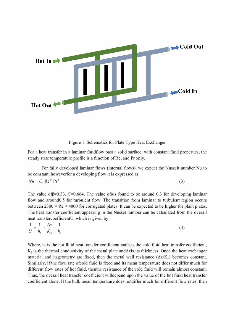
THEORY: The plate heat exchanger normally consists of corrugated plates assembled into a frame. The hot fluid flows in one direction in alternating chambers while the cold fluid flows in true counter-current flow in the other alternating chambers. A schematic diagram of the flow is shown in Figure 1. The fluids are directed into their proper chambers either by a suitable gasket or a weld depending on the type of exchanger chosen. Plate heat exchangers are best known for having overall heat transfer coefficients (U-values) in excess of 3–5 times the U-value in a shell and tube designed for the same service.
Plate heat exchanger is an attractive option when more expensive materials of construction can be employed. The significantly higher U-value results in far less area for a given application. The higher U-values are obtained by inducing turbulence between the plate surfaces. Owing to this they are also known to minimize the fouling.
Heat Transfer Correlation:
Generally the heat transfer correlation for a fluid flow past a solid surface is expressed in a dimensionless form
Pr)(Re,NuNu (1)
where Nu is the non dimensionless Nusselt number expressed as
khDNu
(2)
Figure 1: Schematics for Plate Type Heat Exchanger
For a heat transfer in a laminar fluidflow past a solid surface, with constant fluid properties, the steady state temperature profile is a function of Re, and Pr only.
For fully developed laminar flows (internal flows), we expect the Nusselt number Nu to be constant, howeverfor a developing flow it is expressed as:
PrRe1CNu (3) The value ofβ≈0.33, C=0.664. The value ofαis found to be around 0.3 for developing laminar flow and around0.5 for turbulent flow. The transition from laminar to turbulent region occurs between 2300 ≤ Re ≤ 4000 for corrugated plates. It can be expected to be higher for plain plates. The heat transfer coefficient appearing in the Nusset number can be calculated from the overall heat transfercoefficientU, which is given by
,111oph hK
xhU
(4)
Where, hh is the hot fluid heat transfer coefficient andh0is the cold fluid heat transfer coefficient, Kp is the thermal conductivity of the metal plate and∆xis its thickness. Once the heat exchanger material and itsgeometry are fixed, then the metal wall resistance (∆x/Kp) becomes constant. Similarly, if the flow rate ofcold fluid is fixed and its mean temperature does not differ much for different flow rates of hot fluid, thenthe resistance of the cold fluid will remain almost constant. Thus, the overall heat transfer coefficient willdepend upon the value of the hot fluid heat transfer coefficient alone. If the bulk mean temperature does notdiffer much for different flow rates, then
all the physical properties will remain nearly the same and Eq. (4)can be re-written in combination with Eq. (3) as
CumC
hU h
11 (5)
WhereCis constant. hh can therefore be evaluated from the intercept of the plot of 1/U vs. 1/uα.Thena plot of 1/U vs. 1/=uαwill provide the intercept valueC, which is then used to calculate the heat transfercoefficient from Eq. (5). The Nusselt number correlation can then be found. For the sake of simplicity, it isoften assumed thatα=0.5. This can be verified if the plot of 1/U vs. 1/u0.5 is a straight line for a largerange in the small limit. PROCEDURE: 1. Set the pump to maximum hot fluid flow rate (≈550 lph), and measure the temperature difference between the outlet and inlet of the hot fluid. 2. Set the temperature of the inlet hot fluid in the dual temperature indicator cum controller. The setpoint should be set between 60 to 80OC. 3. Provide cooling water supply to the plate heat exchanger minimum as 100 LPH. This will ensure that the temperature difference is maintained at least 2–3OC. Keep this flow rate constantthroughout the experiment. 4. Connect the 15 A and 5 A plug pins to a stable 230 V A.C. electric supply. Care should be taken toconnect these two pins in different phases of the power supply. Switch on the heater power supply. 5. Adjust the flow rate of hot fluid through the heat exchanger by adjusting the speed of hot fluid circulation pump. This step should be done only when the steady state is reached. 6. To measure the oil flow rate, we have to close the valve beneath the fixed volume container for certain height. By measuring the time required for the hot fluid toachieve certain height, we can calculate the velocity and successively the volumetric flow rate of hot fluid. 7. Repeat step 6 at least for 10 different flow rates. SPECIFICATION: Height of the plate = 120 mm Width of the plate = 65 mm Gap between two plates = 1 mm Number of plates = 7 Number of hot fluid chambers = 3
Number of cold fluid chambers = 4 Zero error of hot fluid digital thermometers δT = Oil in tank = Servo Engine 32 Grade Oil Flash Point (COC) = 190oC Kinematic Viscosity = 32 cS @ 45oC, 5.4 cS @ 100oC. Density of Oil = 857 Kg/m3 Diameter of flow measuring cylinder: 0.0762m Thermal conductivity of the hot fluid: 0.13W/mk Thermal conductivity of stainless steel 16 W/m.K OBSERVATION TABLE: Observation No. Flow rate V
lph Hot fluid temperature (oC) Cold fluid temperature
(oC)
Inlet (T1) Outlet (T2) Inlet (t1) Outlet (t2)
1
2
3
4
5
6
7
8
9
10
CALCULATIONS 1. Total heat transfer area of heat exchanger A = NHW =
2. Cup mean temperature (use any typical value) Tm= (T1+T2)/2=
3. Density of Oil ρ = 857 kg/m3
4. Specific heat of Ethylene glycol atTm Cp =
5. Viscosity of oil at Tm μ =
6. Thermal conductivity of Ethylene glycol atTm K =
7. Prandtl Number for hot fluid K
C pPr =
8. Equivalent diameter bW
WbDe
2 =
SAMPLE CALCULATIONS
1.Flow Rate V =
2. Velocity of hot fluid in a chamber hWbN
Vu =
3. Total heat transferred )( 21 TTVCQ p =
4. Brinkman number )( 21
2
TTKuBr
=
5. Log Mean Temperature Difference (LMTD)= ∆푇 = ( ) ( )
[( )( )]
=
6. Overall heat transfer coefficient LMTA
QU
=
7. Reynolds number uDeRe =
8.Intercept of 1/U vs 1/u0.5plot C = Here C =
ℎ+ ∆
9. Hot fluid heat transfer coefficient CUhi
11 =
10. Nusselt number KDhNu ei
GRAPHS: 1. Plot of 1/Uvs 1/u0.5
2. Plot of Nu number vs Reynolds number
CONCLUSION/DISCUSSION ON THE RESULT
1. Overall heat transfer coefficient and individual heat transfer coefficient in plate type heat exchanger was calculated.
FURTHER READING
G H Hewitt, G L Shires, and T R Bott, “Process Heat Transfer”, CRC Press, NY, 1994