9 Platform for Intelligent Manufacturing Systems with Elements of Knowledge Discovery Tomasz Mączka and Tomasz Żabiński Rzeszów University of Technology Poland 1. Introduction Numerous and significant challenges are currently being faced by manufacturing companies. Product customization demands are constantly growing, customers are expecting shorter delivery times, lower prices, smaller production batches and higher quality. These factors result in significant increase in complexity of production processes and the necessity for continuous optimization. In order to fulfil market demands, managing the production processes require effective support from computer systems and continuous monitoring of manufacturing resources, e.g. machines and employees. In order to provide reliable and accurate data for factory management personnel the computer systems should be integrated with production resources located on the factory floor. Currently, most production systems are characterized by centralized solutions in organizational and software fields. These systems are no longer appropriate, as they are adapted to high volume, low variety and low flexibility production processes. In order to fulfil current demands, enterprises should reduce batch sizes, delivery times, and product life-cycles and increase product variety. In traditional manufacturing systems this would create an unacceptable decrease in efficiency due to high replacements costs, for example. (Christo & Cardeira, 2007) Modern computer systems devoted to manufacturing must be scalable, reconfigurable, expandable and open in the structure. The systems should enable an on-line monitoring, control and maximization of the total use of manufacturing resources as well as support human interactions with the system, especially on the factory floor. Due to vast amounts of data collected by the systems, they should automatically process data about the manufacturing processes, human operators, equipment and material requirements as well as discover valuable knowledge for the factory’s management personnel. The new generation of manufacturing systems which utilizes artificial intelligence techniques for data analyses is referred to as Intelligent Manufacturing Systems (IMS). IMS industrial implementation requires computer and factory automation systems characterized by a distributed structure, direct communication with manufacturing resources and the application of sophisticated embedded devices on a factory floor. (Oztemel, 2010) Many concepts in the field of organizational structures for manufacturing have been proposed in recent years to make IMS a reality. It seems that the most promising concepts www.intechopen.com
Transcript
9
Platform for Intelligent Manufacturing Systems with Elements of Knowledge Discovery
Tomasz Mączka and Tomasz Żabiński Rzeszów University of Technology
Poland
1. Introduction
Numerous and significant challenges are currently being faced by manufacturing companies. Product customization demands are constantly growing, customers are expecting shorter delivery times, lower prices, smaller production batches and higher quality. These factors result in significant increase in complexity of production processes and the necessity for continuous optimization. In order to fulfil market demands, managing the production processes require effective support from computer systems and continuous monitoring of manufacturing resources, e.g. machines and employees. In order to provide reliable and accurate data for factory management personnel the computer systems should be integrated with production resources located on the factory floor.
Currently, most production systems are characterized by centralized solutions in organizational and software fields. These systems are no longer appropriate, as they are adapted to high volume, low variety and low flexibility production processes. In order to fulfil current demands, enterprises should reduce batch sizes, delivery times, and product life-cycles and increase product variety. In traditional manufacturing systems this would create an unacceptable decrease in efficiency due to high replacements costs, for example. (Christo & Cardeira, 2007)
Modern computer systems devoted to manufacturing must be scalable, reconfigurable,
expandable and open in the structure. The systems should enable an on-line monitoring,
control and maximization of the total use of manufacturing resources as well as support
human interactions with the system, especially on the factory floor. Due to vast amounts of
data collected by the systems, they should automatically process data about the
manufacturing processes, human operators, equipment and material requirements as well
as discover valuable knowledge for the factory’s management personnel. The new
generation of manufacturing systems which utilizes artificial intelligence techniques for data
analyses is referred to as Intelligent Manufacturing Systems (IMS). IMS industrial
implementation requires computer and factory automation systems characterized by a
distributed structure, direct communication with manufacturing resources and the
application of sophisticated embedded devices on a factory floor. (Oztemel, 2010)
Many concepts in the field of organizational structures for manufacturing have been proposed in recent years to make IMS a reality. It seems that the most promising concepts
www.intechopen.com
Manufacturing System
184
are: holonic (HMS or Holonic Manufacturing System), fractal, and bionic manufacturing. Further references can be found in (Christo & Cardeira, 2007). In general, it could be stated that a promising organizational structure is a conglomerate of distributed and autonomous units which operate as a set of cooperating entities. It would be impossible to successfully implement the new organizational concepts in the manufacturing industry without suitable distributed control and monitoring hardware and software.
In publications (Leitão, 2008), (Colombo et al., 2006) an agent-based software is designated as technology for industrial IMS realization, regardless of the chosen organizational paradigm. The integration of HMS and multi-agent software technology is currently presented as the most promising foundation for industrial implementations of IMS. The HMS paradigm is based on concepts originally developed by Arthur Koestler in 1969 with reference to social organizations and living organisms. The term holon describes a basic unit of organization and has two important characteristics: autonomy and co-operation. In a manufacturing system, a holon can represent a physical or logical activity, e.g. a machine, robot, order, machine section, flexible manufacturing system and even a human operator. The holon possesses the knowledge about itself and about the environment and has an ability to cooperate with other holons. From this viewpoint, a manufacturing system is a holarchy, which is defined as a system of holons organized in a dynamical hierarchical structure. Manufacturing system goals are achieved by cooperation between holons. Due to conceptual similarities of HMS and agent-based software, it seems clear that their combination should create a promising platform for an industrial IMS implementation.
On the other hand, humans still play an important role in manufacturing systems and in spite of predictions from the seventies, which suggested that human operators would no longer be needed in fully automated production, they even play a more important role nowadays than they did in the past (Oborski, 2004). Proper cooperation between humans and machines or humans and manufacturing control systems can significantly improve overall production effectiveness, so human system interface design is still an active research area. Human System Interfaces (HSI) are responsible for efficient cooperation between operators and computer systems. (Gong, 2009) It seems clear that convenient and reliable human system interaction is a key factor for successful industrial IMS implementation.
In this chapter, results of the project devoted to the development of a hardware and
software platform for IMS are to be described. The platform based on Programmable
Automation Controllers (PAC) has already been successfully tested by being included in
everyday production processes in four small and medium Polish metal component
production companies. The platform was employed in order to monitor production
resources in real-time and to conduct communication between computer systems, machines
and operators. On the basis of the tests results, it has been experimentally proven that the
main development-related barrier for real deployment of IMS (Leitão, 2008), i.e. absence of
industrial controllers with appropriate capabilities, is out-of-date. Within 28 months of the
system operation it has been proven that modern PAC are capable of running data
processing, communication and graphical user interface modules directly on the PAC
controller in parallel with PLC programs. The hardware and software system which has
been created constitutes of a platform for future complete implementation of the IMS.
www.intechopen.com
Platform for Intelligent Manufacturing Systems with Elements of Knowledge Discovery
185
The project has been created by the Department of Computer and Control Engineering, Rzeszów University of Technology, in cooperation with Bernacki Industrial Services company and the students from the Automation and Robotics scientific circle called ROBO (ROBO, 2011). The project has been made under the auspices of Green Forge Innovation Cluster.
The long-term goal of this project is the development and industrial implementation of full IMS concept for small and medium production companies. The goal determines two main assumptions for the selection of hardware and software elements. The first assumption is a possibility to include in the system newer machines with advanced control equipment as well as older ones without controllers. The second one is a reasonable cost of the system. In the paper (Żabiński et al., 2009) the results of the first stage of the project were presented. During the first stage, the hardware was selected and the prototype and functionality limited testbed for one machine was installed in a screw manufacturing factory. The system was tested in a real production process. The first stage of the project was to provide valuable benefits for the factory management board in the field of monitoring availability, performance and quality of operation of the machines and operators. Additionally, control tasks in a PLC layer of the system were done using ST (Structured Text) programming language for the machines which had not been previously equipped with a controller. The success of the first stage resulted in the project continuation and the findings of the current stage are presented in this paper and in (Mączka & Czech, 2010), (Żabiński & Mączka, 2011), (Mączka & Żabiński 2011), (Mączka et al., 2010).
The main goal of the current project stage is to develop and test in a real production environment a system structure with PACs integrated with touchable panels for each machine. Some improvements of HSI for the factory floor are being made, according to suggestions acquired during the first stage, and new functionalities for different organizational units, i.e. maintenance, tool and material departments. The important part of current and future works is to employ artificial intelligence and data mining technology to give factory management personnel reliable and long-term knowledge about the production processes.
2. Systems testbed structures
Up to now, four system industrial testbeds have been constructed. The first one was installed in a screw manufacturing company which is a member of the Green Forge Innovation Cluster. The Green Forge Innovation Cluster is an association of metal production companies and scientific institutions from southern Poland, which aims at innovative solutions development for metal components production. The second one was installed at the WSK PZL-Rzeszów company, in the department which produces major rotating parts for the aviation industry. The first testbed consists of two machine sections formed by cold forging press machines. The first section includes machines without PLC controllers but the second one consists of 12 modern machines equipped with PLCs and advanced cold forge process monitoring devices. The second testbed includes one production line with four CNC vertical turning lathes and two CNC machining centres. The machines in the testbeds have been operated by experienced operators who interact with the system using various peripheral devices, such as barcode readers, electronic calipers and industrial touch panels. (Żabiński & Mączka, 2011) There is also a third testbed installed in a different department at “WSK PZL-Rzeszów”, which monitors one machine.
www.intechopen.com
Manufacturing System
186
During the project, a mobile testbed with GSM communication was also constructed. The purpose of a mobile testbed is to allow production companies to test the system without bearing the costs of communication infrastructure installation. Thanks to such a testbed, companies can better define system functionalities better which are very important for them, taking into account the production profile and organizational structure. Currently, this testbed has been installed in a metal component manufacturing company, where one machine has been monitored. (Mączka & Żabiński, 2011)
In the hardware and software part of the system, three main layers can be distinguished: a factory floor hardware and software, a data server layer and WWW (World Wide Web) client stations.
2.1 Factory floor layer
Due to the scalable, reconfigurable, expandable and open structure of the platform, the industrial implementations differ in functionality as well as in hardware and software elements installed on a factory floor.
2.1.1 Testbed with PACs
In the first implementation type, Programmable Automation Controllers (PACs), also known as embedded PCs, are used on a factory floor. PACs are equipped with operating systems and meet the demands of modern manufacturing systems as they combine features of traditional Programmable Logic Controllers (PLCs) and personal computers (PCs). The main feature of PACs is the ability to use the same device for various tasks simultaneously, e.g. data acquiring, processing and collection; process and motion control; communication with databases or information systems; Graphical User Interface (GUI) implementation, etc. There are two kinds of Windows system available for the controllers, i.e. Windows CE and Windows XP Embedded. Windows CE is equipped with .Net Compact Framework, Windows XP Embedded is equipped with .Net Framework. There are benefits of using the XP Embedded platform, e.g. homogeneity of the software platform for controllers and PC stations as well as availability of network and virus protection software. Due to the financial reasons, Ethernet network for communication and controllers with Windows CE were chosen for the two testbeds.
In the system, PACs acquire data form machines using distributed EtherCAT (Granados, 2006) communication devices equipped with digital or analog inputs. Each PAC is equipped with Windows CE 6.0 operating system, real-time PLC subsystem, UPS (Uninterruptible Power Supply), Ethernet as well as RS-232/485 interfaces for communication and DVI (Digital Visual Interface)/USB (Universal Serial Bus) interfaces for touchable monitors connection. One controller with peripherals, i.e. an industrial 15” touch panel, RFID (Radio-frequency Identification) cards reader and barcode reader, is installed in each machine section or production line. The hardware system structure for a factory floor is shown in Fig. 1.
The software for PACs consist of two layers. The first layer is PLC software written in ST (Structured Text) language, which is mainly responsible for reading and writing physical inputs and outputs. The second layer constitutes the application written in C# language for .NET Compact Framework (CF), which runs under Windows CE. (Microsoft Developer Network, 2011)
www.intechopen.com
Platform for Intelligent Manufacturing Systems with Elements of Knowledge Discovery
187
The second layer consists of the following modules:
• the module for communication between the PLC program and other system parts,
• the module for communication with database using web services technology,
• the operator’s GUI.
Fig. 1. Hardware structure of the platform for the first implementation type
PLC control programs run in the PLC layer on the same device simultaneously with GUI, data processing and database communication modules which run in Windows CE layer (Fig. 2). The ADS (Automation Device Specification) protocol enables C# programs to read and write data directly from and to PLC programs via names of PLC variables. It significantly simplifies the communication between PLC and C# applications.
Fig. 2. PAC software structure
The PLC and Windows software for embedded PC controller was designed and implemented in order to control up to 6 machines. It gives flexibility in the system structure, e.g. for more demanding PLC or CNC control tasks there is a configuration of one controller for one
www.intechopen.com
Manufacturing System
188
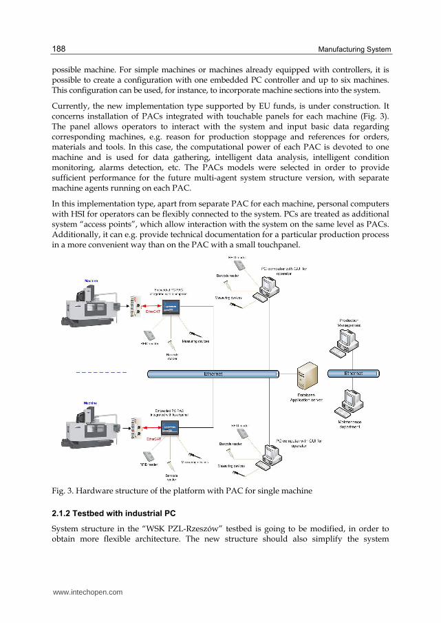
possible machine. For simple machines or machines already equipped with controllers, it is possible to create a configuration with one embedded PC controller and up to six machines. This configuration can be used, for instance, to incorporate machine sections into the system.
Currently, the new implementation type supported by EU funds, is under construction. It concerns installation of PACs integrated with touchable panels for each machine (Fig. 3). The panel allows operators to interact with the system and input basic data regarding corresponding machines, e.g. reason for production stoppage and references for orders, materials and tools. In this case, the computational power of each PAC is devoted to one machine and is used for data gathering, intelligent data analysis, intelligent condition monitoring, alarms detection, etc. The PACs models were selected in order to provide sufficient performance for the future multi-agent system structure version, with separate machine agents running on each PAC.
In this implementation type, apart from separate PAC for each machine, personal computers with HSI for operators can be flexibly connected to the system. PCs are treated as additional system “access points”, which allow interaction with the system on the same level as PACs. Additionally, it can e.g. provide technical documentation for a particular production process in a more convenient way than on the PAC with a small touchpanel.
Fig. 3. Hardware structure of the platform with PAC for single machine
2.1.2 Testbed with industrial PC
System structure in the “WSK PZL-Rzeszów” testbed is going to be modified, in order to obtain more flexible architecture. The new structure should also simplify the system
www.intechopen.com
Platform for Intelligent Manufacturing Systems with Elements of Knowledge Discovery
189
implementation in companies with various production and data resources. The new software structure should enable its easy adaptation to the needs of other production sectors. During the development of the testbed, additional diagnostics and process monitoring equipment will be included in the system, e.g. quality measurement devices, current and force sensors, etc. In concern to the WSK testbed, it is planned to include an additional 64 machines in the system. Due to customer demands, one industrial PC computer will be installed for each production line. The industrial PC’s task is monitoring states of the machines included in particular production line on base of digital (machine work mode, machine engine state) and analog (spindle load) signals from machines’ control systems. Windows XP Embedded with real-time and soft PLC TwinCAT subsystem is the operating environment for industrial PC; connection with input/output modules is performed via EtherCAT bus using star network topology. Chosen topology minimizes communication problems if some part of the EtherCAT network infrastructure will fail, e.g. in case of network cable break.
In this type of implementation, machine operators interact with the system using PCs workstations, placed near monitored machines. The basic scope of data, which can be viewed and input carried out by operators, is similar like in PAC implementation. Detailed description will be given in section 3.1.
Additionally, the system is going to be integrated with an SAP business software and will be used for delivering electronic versions of technical and quality control documents directly to operators’ workstations. The system should support production management as well as support the maintenance department by the usage of advanced and intelligent machine condition monitoring software tools. The new testbed structure is shown in Fig. 4. (Żabiński & Mączka 2011)
Fig. 4. Hardware structure with industrial PC
www.intechopen.com
Manufacturing System
190
2.2 Data server and end clients layer
The data and application server layer is common for all the structures. It includes the
PostgreSQL database server and the GlashFish application server. GlassFish is an open-
source application server compatible with Java Platform Enterprise Edition (J2EE).
(GlassFish Community, 2011) PostgreSQL is open source object-relational database system
which conforms to the ANSI-SQL (Structured Query Language) 2008 standard.
(PostgreSQL, 2011) The application server hosts communication and data processing
modules with web services written in Java. The WWW client layer utilizes websites written
in JSF (Java Server Faces), JSP (Java Server Pages), AJAX (Asynchronous Javascript and
XML) and also works under GlassFish server control. Communication between PACs or PCs
and the database and between the presentation layer and the database is performed using
web services or Enterprise Java Beans (EJB) technology.
3. Human system interfaces
Human System Interface, which was developed for the IMS project, consists of two main
layers, i.e. a factory floor layer and a WWW layer. The first layer is a GUI application which
runs on an embedded PC installed on the factory floor. In this layer the communication
between an operator and the system is done via a 15” touchable monitor. The second layer is
a web page accessed through a web browser from the factory intranet or the Internet. The
Polish language is used in HSI, as the system has been installed in Polish factories. Due to
this reason, the GUI language presented in this section is Polish.
3.1 Factory floor layer
The HSI for factory floor layer has two main operation modes, i.e. locked and unlocked. In
the locked mode an operator can only observe information presented on the screen. In the
unlocked mode an operator can interact with the system. An operator can change the HSI
mode using his RFID card. Thanks to the RFID operator’s badges a security policy was
implemented on the factory floor. In the locked mode visual information of machines
operation mode, production plan and plan realization and the necessity of an operator
interaction with the system is presented. The necessity of an operator interaction with the
system is indicated by the blinking of a panel associated with the machine which needs
intervention. The locked mode screen for a machine section with six machines is
presented in Fig. 5.
In the unlocked HSI mode an operator can perform various tasks connected with the
system, e.g. login, logout, taking up shift, order selection or confirmation, stop reason and
quality control data input etc. The unlocked mode screen for a machine section with six
machines is presented in Fig. 6.
The HSI consists of two main sections, i.e. the system section (it allows login, logout, etc.) and the machines section (it allows data input for particular machines). Small rectangles with letters O, SR, QC, S, associated with each machine panel (a large rectangle with machine name, e.g. Tłocznia T-19), indicates the action which should be performed for the particular machine, i.e. O – order selection or confirmation, SR – stop reason input, QC – quality control data input and S – service. When the machine panel is blinking, an operator
www.intechopen.com
Platform for Intelligent Manufacturing Systems with Elements of Knowledge Discovery
191
can quickly determine the operation which should be performed, the color of the letters O, QC, SR or S becomes red for the active action. An example of an order input screen is shown in Fig. 7. Operators can input order code using on-screen keyboard or via barcode reader. (Żabiński & Mączka, 2011)
Fig. 5. The factory floor HSI locked mode screen for six machines
Fig. 6. The factory floor HSI unlocked mode screen for six machines
www.intechopen.com
Manufacturing System
192
Fig. 7. Order inputting screen for particular machine
3.2 WWW layer
The WWW layer includes two main modules, i.e. an on-line view and statistics. The on-line
view enables on-line monitoring of machines operation mode, e.g. production, stoppage,
lack of operator and also other information like: operator identifier, order identifier, shift
production quantity, daily machine operation structure or detailed history of events. The
on-line view for a production hall is presented in Fig. 8.
Fig. 8. Production state on-line view for a production hall
www.intechopen.com
Platform for Intelligent Manufacturing Systems with Elements of Knowledge Discovery
193
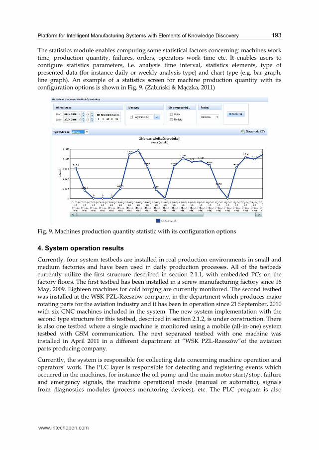
The statistics module enables computing some statistical factors concerning: machines work time, production quantity, failures, orders, operators work time etc. It enables users to configure statistics parameters, i.e. analysis time interval, statistics elements, type of presented data (for instance daily or weekly analysis type) and chart type (e.g. bar graph, line graph). An example of a statistics screen for machine production quantity with its configuration options is shown in Fig. 9. (Żabiński & Mączka, 2011)
Fig. 9. Machines production quantity statistic with its configuration options
4. System operation results
Currently, four system testbeds are installed in real production environments in small and medium factories and have been used in daily production processes. All of the testbeds currently utilize the first structure described in section 2.1.1, with embedded PCs on the factory floors. The first testbed has been installed in a screw manufacturing factory since 16 May, 2009. Eighteen machines for cold forging are currently monitored. The second testbed was installed at the WSK PZL-Rzeszów company, in the department which produces major rotating parts for the aviation industry and it has been in operation since 21 September, 2010 with six CNC machines included in the system. The new system implementation with the second type structure for this testbed, described in section 2.1.2, is under construction. There is also one testbed where a single machine is monitored using a mobile (all-in-one) system testbed with GSM communication. The next separated testbed with one machine was installed in April 2011 in a different department at “WSK PZL-Rzeszów”of the aviation parts producing company.
Currently, the system is responsible for collecting data concerning machine operation and operators’ work. The PLC layer is responsible for detecting and registering events which occurred in the machines, for instance the oil pump and the main motor start/stop, failure and emergency signals, the machine operational mode (manual or automatic), signals from diagnostics modules (process monitoring devices), etc. The PLC program is also
www.intechopen.com
Manufacturing System
194
responsible for registering the quantity produced. Information about events, including timestamps, machine and operator identifiers and other additional parameters, is stored in the database. Two mechanisms are used to store data in the database, such as: an asynchronous event driven method and a synchronous one with a 10 second time period for diagnostics purposes. The system is also responsible for detecting and storing information on breakdowns, setup and adjustments, minor stoppages, reduced speed etc. Every production stoppage must be assigned with an appropriate reason. Tool failure, for example, are automatically detected, while others have to be manually chosen by operators via the HSI.
On the server side, there are software modules used for calculating different KPIs (Key Performance Indicators), e.g. production efficiency, equipment and operators efficiency etc. The real production quantity report as a function of day, calculated for time interval from 1-03-2011 to 31-03-2011 for 6 machines, is presented in Fig. 10. During this period, the planned production time for the machines was 24 hours per day (3 shifts). As shown in Fig. 10, there were some fluctuations of production quantity.
Fig. 10. Production quantity report – number of produced items as a function of days
A machine operation time structure is analyzed and can be shown as a horizontal graph (Fig. 11). At the moment there is a possibility of analyzing data from three points of view: a general view, a view with stop reasons and a detailed view. The general view divides machine operational time into three categories, i.e. the operator’s absence, the automatic production and the stoppage. In the analysis for the view with stop reasons, each stoppage time period is associated with the appropriate stop reason. In the detailed view, periods of the manual machine operation are distinguished in each stoppage time. Different colors are designated for appropriate time intervals (Fig. 11), e.g. the stoppage – light brown, the automatic production – green, the manual operation – dark green, the start-up time – blue, the electrical breakdown – red, etc.
During the long term test, when the system was included in the regular daily production, it was proven that the selected hardware and software platform is suitable for industrial
www.intechopen.com
Platform for Intelligent Manufacturing Systems with Elements of Knowledge Discovery
195
implementation of the IMS. The software modules (HSI, communication, web services, data acquisition) for Windows CE have been running successfully on the embedded PC controller in parallel to PLC programs. (Mączka & Czech, 2010)
Fig. 11. Machine operation time structure with stop reasons
Within 704 days of system operation in the screws production testbed, the whole number of events registered in the testbed was 3,883,374. The system covers: production monitoring, quality control, material and tools management and also fundamental support for the maintenance department. In the company which produces aviation parts, 57,230 events were registered within 59 days of system operation.
5. Association rules application for knowledge discovery
Taking into account the limited number of machines included in the currently working system testbeds, it can be stated that the number of data collected is considerable. A long-term data analysis to make reasoning and generalized conclusions about production processes would be a demanding task for human analysts. Therefore, there is a need to employ artificial intelligence and data mining technology to give factory management personnel reliable knowledge of the production processes. In this section, the results of the initial tests in the areas of applying data mining and artificial intelligence techniques to discover knowledge about the production processes, are to be described.
It is expected that continuously discovered knowledge will support everyday production process management and control, thus providing the answers to numerous questions, e.g. what are the bottlenecks in the production systems etc. Moreover, it is envisaged that the system will be able to automatically identify relationships in the production systems, discover possibilities for more effective usage of production resources and use Statistical Process Control (SPC) with artificial intelligence support for early detection of possible problems in production systems.
Initial work in this area concerns the creation of tools for automatic rules (patterns) generation, which will describe relations between values in the database. The discovered patterns could be used for detecting operators’ improper actions, which could have an influence on machine operation, e.g. increasing downtime duration and number of breakdowns. The rules are referred to as association rules.
5.1 Introduction to the experiment
The goal of association rules is to detect relationships between specific values of categorical variables in large data sets.
www.intechopen.com
Manufacturing System
196
The formal definition of the problem is as follows: Let D = {t1; t2; …; tm} be a set of m transactions, called data set or database. Let I = {i1; i2; …; in} be a set of possible n binary
attributes for transaction, called items. Single transaction T is a set of items such that T ⊆ I.
Assume that X is a set of some items from I, so X ⊆ I. A transaction T contains X if the
transaction contains all items from X, so X ⊆ T.
An association rule is an implication of the form X => Y, where X ⊂ I, Y ⊂ I, and X ∩ Y=∅.
The rule X => Y holds in the transaction set D with confidence c if c% of transactions in D
that contain X also contain Y. The rule X => Y has support s in the transaction set D if s% of
transactions in D contain X ∪ Y. Given a set of transactions D, the problem of mining
association rules is to generate all association rules that have support and confidence greater
than the user-specified minimum support (minsup) and minimum confidence (minconf)
respectively. (Agrawal & Srikant, 1994).
The experiment of finding association rules in production data has been performed. The first step of the experiment was to choose the subset of data to analyze, i.e. time period and attributes, and to extract raw data from screw manufacturing company database to CSV (Comma Separated Values) text format. CSV format was chosen because of the possibility of loading data directly into data mining software, i.e. Statistica or Weka. 127232 events registered on 12 machines from 4.01.2011 to 16.07.2011, concerning machine operational state, were extracted using SQL query and pgAdmin database management tool. The structure of events is shown in Table 1, the table contains only a subset of registered events.
plc_time event_type_id machine_id
2011-01-04 07:59:25.784 2000 41
2011-01-04 08:26:27.565 2001 41
2011-01-04 08:28:49.845 2000 41
2011-01-04 08:29:42.705 2001 41
2011-06-14 21:49:38.032 2000 44
2011-06-14 23:29:17.732 2001 44
2011-07-11 06:59:49.812 2000 68
2011-07-11 07:35:15.332 2001 68
2011-07-11 07:41:44.872 2000 68
2011-07-11 08:21:07.812 2001 68
Table 1. Structure of raw events extracted from production database
www.intechopen.com
Platform for Intelligent Manufacturing Systems with Elements of Knowledge Discovery
197
Attributes of a single event are:
• plc_time– time of event registration in the PLC layer
• event_type_id– type of registered event, 2000 is production start, 2001 is production stop
• machine_id– identifier of a machine for which the event was registered
After consultation with the company production management personnel, an assumption
has been made that length of times of continuous machine state, i.e. length of production
and length of stoppage will be important factor to analyze. It seems to be clear that if
continuous production time of a particular machine lasts longer than the others, this
machine works more efficiently, without the need for operator action. It is worthwhile
noticing that lower number of stoppages should positively affect machine lifetime and
save energy.
5.2 Data preparation
The format for raw data presentation in Table 1 is not useful for discovering associations
concerning machines continuous interval length, as raw events do not directly reflect
particular machine state during a particular period of time. Because of this, data needs to be
pre-processed to the list of production and stoppage intervals for each machine. Each record
should contain interval start date, interval end date and interval length. Pre-processing task
was done using Python script, which analyzes events list and produces stoppage intervals, if
the current analyzed event is 2001 (production stop) and next analyzed event is 2000
(production start). In the opposite situation, production interval is inserted to the result list.
Data structure after the pre-processing phase is shown in Table 2.
start End type length_min machine_id
2011-01-04 07:59:25.784
2011-01-04 08:26:27.565 W 27.03 41
2011-01-04 08:26:27.565
2011-01-04 08:28:49.845 S 2.37 41
2011-01-04 08:28:49.845
2011-01-04 08:29:42.705 W 0.88 41
…
2011-06-14 21:49:38.032
2011-06-14 23:29:17.732 W 99.66 44
…
2011-07-11 06:59:49.812
2011-07-11 07:35:15.332 W 35.43 68
2011-07-11 07:35:15.332
2011-07-11 07:41:44.872 S 6.49 68
2011-07-11 07:41:44.872
2011-07-11 08:21:07.812 W 39.38 68
Table 2. Data structure after the pre-processing phase
www.intechopen.com
Manufacturing System
198
Attributes of single interval:
• start – timestamp of interval begin,
• end – timestamp of interval end,
• type – interval type, W is work, S is stoppage,
• len_min – interval time length in minutes,
• machine_id – identifier of machine associated with interval.
Start and end timestamps has only informational role and they are omitted in the process of finding associated rules. However, data presented in Table 2 are not ready for application of associated rules finding algorithms. It results from fact, that known association rules discovering algorithms deals with data, whose attributes have discrete or categorical values. In above case, attributes type and machine_id are categorical, but len_min has continuous values. The solution of this problem is mapping attributes with continuous values to categorical attributes, referred in (Agrawal & Srikant, 1996) as partitioning quantitative attributes.
This transformation was, like the previous, performed by Python script. Number of categories and length of each category’s interval were chosen based on minimum and maximum values of len_min, in order to obtain regular distribution of data in generated categories. 46 categories were generated, starting from [0-0.1m] (interval length greater than 0 to 0.1 minutes, or 10 seconds) to [700-+Inf m] (interval length greater of equal 700 minutes). Example values of processed items are contained in table 3. Letter ‘M’ was added before machines identifiers to indicate that this is categorical, not numerical attribute.
start End type length_category machine_id
2011-01-04 07:59:25.784
2011-01-04 08:26:27.565 W [20.1-30.1m] M41
2011-01-04 08:26:27.565
2011-01-04 08:28:49.845 S [2.1-3.1m] M41
2011-01-04 08:28:49.845
2011-01-04 08:29:42.705 W [0.8-0.9m] M41
…
2011-06-14 21:49:38.032
2011-06-14 23:29:17.732 W [90.1-100.1m] M44
…
2011-07-11 06:59:49.812
2011-07-11 07:35:15.332 W [30.1-40.1m] M68
2011-07-11 07:35:15.332
2011-07-11 07:41:44.872 S [6.1-7.1m] M68
2011-07-11 07:41:44.872
2011-07-11 08:21:07.812 W [30.1-40.1m] M68
Table 3. Data after partitioning quantitive attribute len_min to categorical attribute length_category
www.intechopen.com
Platform for Intelligent Manufacturing Systems with Elements of Knowledge Discovery
199
5.3 Finding association rules using Weka
For finding associations in previously prepared data, Weka (Waikato Environment for Knowledge Analysis) software was used. This is a popular suite of a machine learning software written in Java that was developed at the University of Waikato, which is available under the GNU General Public License. Weka is a collection of machine learning algorithms for data mining tasks. Weka contains tools for not only for association rules, but also for classification, regression, clustering and visualization. Its architecture is well-suited for developing new machine learning schemes. (Hall et al., 2009)
In the first step, Weka knowledge explorer was run and preprocessed mining dataset was loaded from CSV file. Weka displays list of attributes in dataset and its basic information like categories, number of items in each category etc. (Fig. 12).
Fig. 12. Weka initial screen after data loading
The next step was running module for association rules generation, choosing algorithm for mining rules and configuring algorithm‘s parameters. Weka provides few rules discovering algorithms, including Apriori, Predictive Apriori, Generalized Sequential Patterns. In the described experiment, most popular Apriori algorithm was selected with parameters:
www.intechopen.com
Manufacturing System
200
support 0.1 (10%), confidence 0.3 (30%). The small value of support was choosen experimentally to not omit rules for particular machines, and purpose of 30% confidence was to ignore irrelevant rules, which applies only to relative small part of data set. Configuration parameters are shown in Fig. 13.
Platform for Intelligent Manufacturing Systems with Elements of Knowledge Discovery
201
Number of records which contain attributes values listed in predecessor and consequent are
present in bracket squares. Some potentially interesting rules are underlined, their
interpretation may be as follows.
Rules 1 and 2 indicates that for machine M67 and M68, production or stoppage interval lasts
usually relatively short – from above 0 to 10 seconds. It suggests that listed machines may
have some troubles with stable work, which can lead to low efficiency. Potential reasons of
this situation are mechanical problems, improper material, improper operator’s actions etc.
This situation is also covered by rules 8 and 10, where predecessor and consequent are
reversed, these rules are more general.
On the other hand, 48% of work intervals and 35% of stoppage intervals lasts up to 10
seconds, so short time intervals can be, in some level, screw production profile and pushing
process specific. However, such potential problem appears to be interesting for deeper
analyze by experts from production manager personnel.
5.4 Finding association rules with Statistica
The same experiment like in 5.3 was performed in Statistica 10 Data Miner. This commercial software includes modules for neural network, clusterization, classification trees etc. (StatSoft, 2011) For the association rules mining, module called basket analysis is available. It includes only one rules finding algorithm, the same like used in previous experiment, i.e. Apriori.
Rules found by Statistica, shown in Fig. 14, are the same like in previous experiment, where
non-commercial Weka software was used.
Fig. 14. Association rules found by Statistica‘s basket analysis module
www.intechopen.com
Manufacturing System
202
6. Conclusion
So far the project devoted to preparing platform for industrial implementation of Intelligent Manufacturing System, the hardware and software has been selected and tested in a real production process using the preliminary testbeds. Currently, the platform is mainly used for data collection concerning the production processes, machine operation and operators’ work. It also provides HSI for machines’ operators and system end-users, i.e. factory management board.
The hardware and software layer, which has already been installed in the factory, has created the need and the basis for the employment of advanced data mining and artificial intelligence techniques and multi-agent software structure in the system. Such techniques could be used for detecting operators’ improper actions which could have an influence on machines operation, e.g. increasing downtime duration and number of breakdowns. The analysis of the rules could probably give an answer to the following questions, e.g. what factors and in what manner influence production processes, under what circumstances problems occur, how operators react to diagnostic messages, etc. So far, experiment of finding association rules from the data gathered by production monitoring system was performed for the fixed range of events concerning 12 machines work. Some potentially interesting rules, which can help the factories management personnel to detect and eliminate bottlenecks in the production processes, were discovered. Process of finding association rules is not currently automated, but thanks to open source data mining software Weka, it can be easily integrated with the existing system infrastructure. Remaining work to be done in this area includes extending events attributes list, by adding for each item in data set product type identifier and machine’s operators identifier. Experiments with different types of rules discovering algorithms, i.e. Apriori Predictive and Generalized Sequence Patterns, will be also performed. Eventually, the system should automatically generate rules, which help to detect the possibility of the problem occurrence on the basis of historical data. Additionally it should suggest the best solution to the problem, therefore the probability of stoppages will be reduced.
New system structures are being developed in order to simplify the system implementation in companies with various production and data resources. The goal is to achieve easy adaptation to the needs of many production sectors. Some of these structures can decrease the cost of system deployment, as popular devices like personal computers can be used on condition that the factory floor is appropriately adaptable, e.g. if there is no oil mist.
However, it should be clearly stated that for industrial implementation of IMS, the structure with separate PAC installed for each machine seems to be the most promising. PAC computational power allows running separate machine agents for each machine, so one of new organizational structure, e.g. holonic, can be implemented.
Tests of new system versions, especially those with multi-agent solutions, are going to be performed with the usage of the laboratory Flexible Manufacturing System (FMS) testbed, presented in Fig. 15. The FMS testbed consists of an integrated CNC milling machine, robot and vision system.
Current results of the project give promising perspectives for an advanced Intelligent Manufacturing System development and implementation with PACs as hardware platform in a real factory for next project stages.
www.intechopen.com
Platform for Intelligent Manufacturing Systems with Elements of Knowledge Discovery
203
Fig. 15. Laboratory FMS testbed
7. Acknowledgment
FMS testbed was bought as a part of the project No POPW.01.03.00-18-012/09 from the Structural Funds, The Development of Eastern Poland Operational Programme co-financed by the European Union, the European Regional Development Fund.
8. References
Agrawal R., Srikant R. (1994). Fast Algorithms for Mining Association Rules in Large Databases. VLDB'94, Proceedings of 20th International Conference on Very Large Data Bases, pp. 487-499, ISBN 1-55860-153-8, Morgan Kaufmann, Santiago de Chile, Chile, 1994.
Agrawal R., Srikant R. (1996). Mining quantitative association rules in large relational tables. Proceedings of the 1996 ACM SIGMOD international conference on Management of data, pp. 1 - 12, ISBN 0-89791-794-4, ACM New York, NY, USA, 1996.
Christo C., Cardeira C. (2007). Trends in Intelligent Manufacturing, Proceedings of IEEE International Symposium on Industrial Electronics, pp. 3209-3214, ISBN 978-1-4244-0754-5, Vigo, Spain, June 4-7, 2007.
Colombo A., Schoop R., Neubert R. (2006). An Agent-Based Intelligent Control Platform for Industrial Holonic Manufacturing Systems, IEEE Trans. Ind. Elect., vol. 53, no. 1, pp. 322-337, ISSN: 0278-0046, Seligenstadt, Germany, February 2006.
GlassFish Community (2011). GlassFish Server Open Source Edition, 23.11.2011, Available from: http://glassfish.java.net/.
Gong C. (2009). Human-Machine Interface: Design Principles of Visual Information. Human-Machine Interface Design. In: Proc IEEE Conference on Intelligent Human-Machine Systems and Cybernetics, pp 262–265, San Antonio Texas, USA, 2009.
www.intechopen.com
Manufacturing System
204
Granados F. (2006). Analysis: Industrial Ethernet - Driving the growth, Computing & Control Engineering Journal, vol.17, no.6, pp.14-15, Dec.-Jan. 2006.
Hall M., Frank E., Holmes G., Pfahringer B., Reutemann P., Witten I. (2009). The WEKA Data Mining Software: An Update, pp.10-18, SIGKDD Explorations, Volume 11, Issue 1, ACM New York, NY, USA, 2009.
Leitão P. (2008). Agent-based distributed manufacturing control: A state-of-the-art survey. Engineering Applications of Artificial Intelligence, No. 22 (7), pp. 979-991, ISBN 0952-1976, ELSEVIER, 2008.
Microsoft Developer Network (2011). C# Language Specification, 23.11.2011, Available from http://msdn.microsoft.com/en-us/library/aa645596(v=vs.71).aspx.
Mączka T., Czech T. (2010). Manufacturing Control and Monitoring System – Concept and Implementation. Proceedings of IEEE International Symposium on Industrial Electronics, t.1, p.3900-3905, Bari, Italy, July 4-7 2010.
Mączka T., Żabiński T. (2011). System for remote machines and operators monitoring - selected elements (in Polish). Pomiary Automatyka Robotyka, p. 62-65, No. 3/2011.
Mączka T., Czech T., Żabiński T (2010). Innovative production control and monitoring system as element of factory of future (in Polish). Pomiary Automatyka Robotyka, p.22-25, No. 2/2010.
Oborski P. (2004). Man-machine interactions in advanced manufacturing systems. The International Journal of Advanced Manufacturing Technology, Vol. 23. No. 3-4, pp 227-232, ISSN: 1433-3015, Springer-Link, 2004.
Oztemel E. (2010). Intelligent manufacturing systems. L. Benyoucef, B. Grabot, (Ed.) Artificial Intelligence Techniques for Networked Manufacturing Enterprises Management, pp. 1-41, ISBN 978-1-84996-118-9, Springer-Verlag, London, 2010.
PostgreSQL (2011). About, 23.11.2011, Available from: http://www.postgresql.org/about/. ROBO (2011). Student Automation and Robotics scientific circle ROBO (in Polish), 23.11.2011,
Available from http://www.robo.kia.prz.edu.pl/. StatSoft (2011). STATISTICA Product Overview, 23.11.2011, Available from http://www.statsoft.com/products/. Żabiński T., Mączka T. (2011). Implementation of Human-System Interface for
Manufacturing Organizations. Human-Computer Systems Interaction. Backgrounds and Applications 2, Advances in Soft Computing, Springer-Verlag Co., 2011.
Żabiński T., Mączka T., Jędrzejec B. (2009). Control and Monitoring System for Intelligent Manufacturing – Hardware and Communication Software Structure. Proceedings of Computer Methods and Systems, p. 135-140, Kraków, Poland, November 26-27 2009.
www.intechopen.com
Manufacturing SystemEdited by Dr. Faieza Abdul Aziz
ISBN 978-953-51-0530-5Hard cover, 448 pagesPublisher InTechPublished online 16, May, 2012Published in print edition May, 2012
InTech ChinaUnit 405, Office Block, Hotel Equatorial Shanghai No.65, Yan An Road (West), Shanghai, 200040, China Phone: +86-21-62489820 Fax: +86-21-62489821
This book attempts to bring together selected recent advances, tools, application and new ideas inmanufacturing systems. Manufacturing system comprise of equipment, products, people, information, controland support functions for the competitive development to satisfy market needs. It provides a comprehensivecollection of papers on the latest fundamental and applied industrial research. The book will be of greatinterest to those involved in manufacturing engineering, systems and management and those involved inmanufacturing research.
How to referenceIn order to correctly reference this scholarly work, feel free to copy and paste the following:
Tomasz Mączka and Tomasz Żabiński (2012). Platform for Intelligent Manufacturing Systems with Elements ofKnowledge Discovery, Manufacturing System, Dr. Faieza Abdul Aziz (Ed.), ISBN: 978-953-51-0530-5, InTech,Available from: http://www.intechopen.com/books/manufacturing-system/platform-for-intelligent-manufacturing-systems-with-elements-of-knowledge-discovery


![Real-time Manufacturing Integration and Intelligence ...integrated & intelligent manufacturing system [14]. Ying G. presented agent-based intelligent system to support coordinate manufacturing](https://static.documents.pub/doc/80x56/60440b95f372e531ef6f25ee/real-time-manufacturing-integration-and-intelligence-integrated-intelligent.jpg)

