PLC Based SCADA for Micro Hydroelectric
Power Plants
Ercan Nurcan Yilmaz Department of Electrical & Electronic Engineering, Faculty of Technology, Gazi University, 06500, Teknikokullar,
Ankara, Turkey
Email: [email protected]
Mehmet Karayel Vocational School, Çankırı Karatekin University, Çankırı, Turkey
Email: [email protected]
Abstract—The demand for electrical energy in the world is
increasing every year. Hydroelectric Power Plants (HPP) in
electricity generation are method is very commonly used.
Hydroelectric power plants are huge facilities and occupy
large areas. Hydroelectric power plants have a lot of special
control and commination systems. Along with the increasing
number of hydroelectric power plants applications, the need
for the education of those systems has been unavoidable in
engineering education. Training hydroelectric power plants,
especially theoretically continue in the field of engineering.
This is a problem. In this study, a prototype has been
developed. Improved Micro Hydroelectric Power Plants
(MHPP) by analyzing the performance of the prototype, the
model are validated.
Index Terms—hydroelectric power plant, engineering
education, PLC, SCADA
I. INTRODUCTION
The increasing demand for electrical energy is one of
the vital problems in the world. People use any kind of
energy sources for fulfilling their energy demand. One of
these energy sources is the hydro power. Total amount of
water in the world is about 1.4 billion miles. Main
sources of water are; 97.5% as salt water in the oceans
and seas, 2.5% is available as fresh water in the rivers and
lakes [1]. Electricity production from water sources is
also an important field of study for engineering.
An uneducated engineer theoretically is bad a
practitioner applicators. Practicing hydroelectric power
plants training, which is an expensive investment, in the
laboratory is very difficult. İnterest of engineers with
insufficient training reduces in this field. Therefore these
problems cause to misuse or not using water resources for
power generation properly.
In this application, a very small powerful MHPP
prototype is designed and developed as a closed loop.
Thus, for training in HPP, an actual experiment prototype
was developed. In addition, with minor revisions, this
system can be used as a real application. In this designed
closed-loop flow HPP prototype, rate control method is
Manuscript received March 12, 2015; revised December 31, 2015.
used. The main reason for choosing this method is to gain
a similar system like a large type HPP’s control structure.
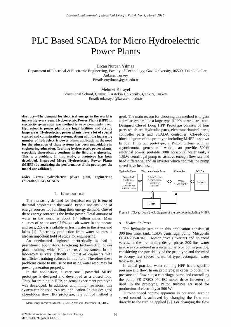
Designed Closed Loop HPP Prototype consists of four
parts which are Hydraulic parts, electromechanical parts,
controller parts and SCADA controller. Closed-loop
block diagram of the prototype including MHPP is shown
In Fig. 1. In our prototype, a Pelton turbine with an
asynchronous generator which can provide 500W
electrical power, portable 300lt horizontal water tank, a
1.5kW centrifugal pump to achieve enough flow rate and
head differential and an inverter which controls the pump
speed have been used.
Figure 1. Closed-Loop block diagram of the prototype including MHPP.
A. Hydraulic Parts
The hydraulic section in this application consists of
300 liter water tank, 1.5kW centrifugal pump, Mitsubishi
FR-D720S-070-EC Motor drive (inverter) and solenoid
valves. In the preliminary design phase, 300 liter water
tank was considered in a rectangular type but in practice,
considering the portability of the prototype and the mind
to occupy less space, horizontal type rectangular water
tank was used.
In actual practice, water running HPP has a specific
pressure and flow. In our prototype, in order to obtain the
pressure and flow rate, a centrifugal pump and controlling
the pump FR-D720S-070-EC motor drive (inverter) is
used. In the prototype, Pelton turbines are used for
production of electricity at 500 W.
Turbine speed control apparatus is not used; turbine
speed control is achieved by changing the flow rate
directly to the turbine applied [2]. For changing the flow
International Journal of Electrical Energy, Vol. 4, No. 1, March 2016
©2016 International Journal of Electrical Energy 67doi: 10.18178/ijoee.4.1.67-70
rate applied to the turbine engine and the pump drive is
provided by changing the frequency.
Solenoid valves which were used in the hydraulic
section, butterfly valve and bypass valve, which exist in
HPP, were used in order to provide near real valve
control in the simulation settings [3]. In the system to
simulate penstock 2 inch PVC pipe and as Bypass pipe 1
inch PVC pipe were used in order to provide the flow rate
needed by Pelton turbine. Depending on the size of the
pipe, instead of butterfly valve, 2-inch solenoid valve was
also instead of bypass valve; 1 inch solenoid valve was
used. These valves can be controlled both manual and
automatically via SCADA (they are also suitable for HPP
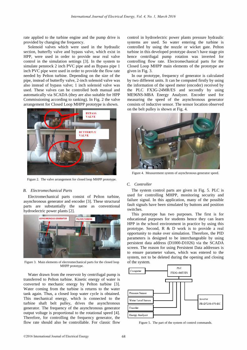
Commissioning according to ranking). In Fig. 2 the valve
arrangement for Closed Loop MHPP prototype is shown.
Figure 2. The valve arrangement for closed loop MHPP prototype.
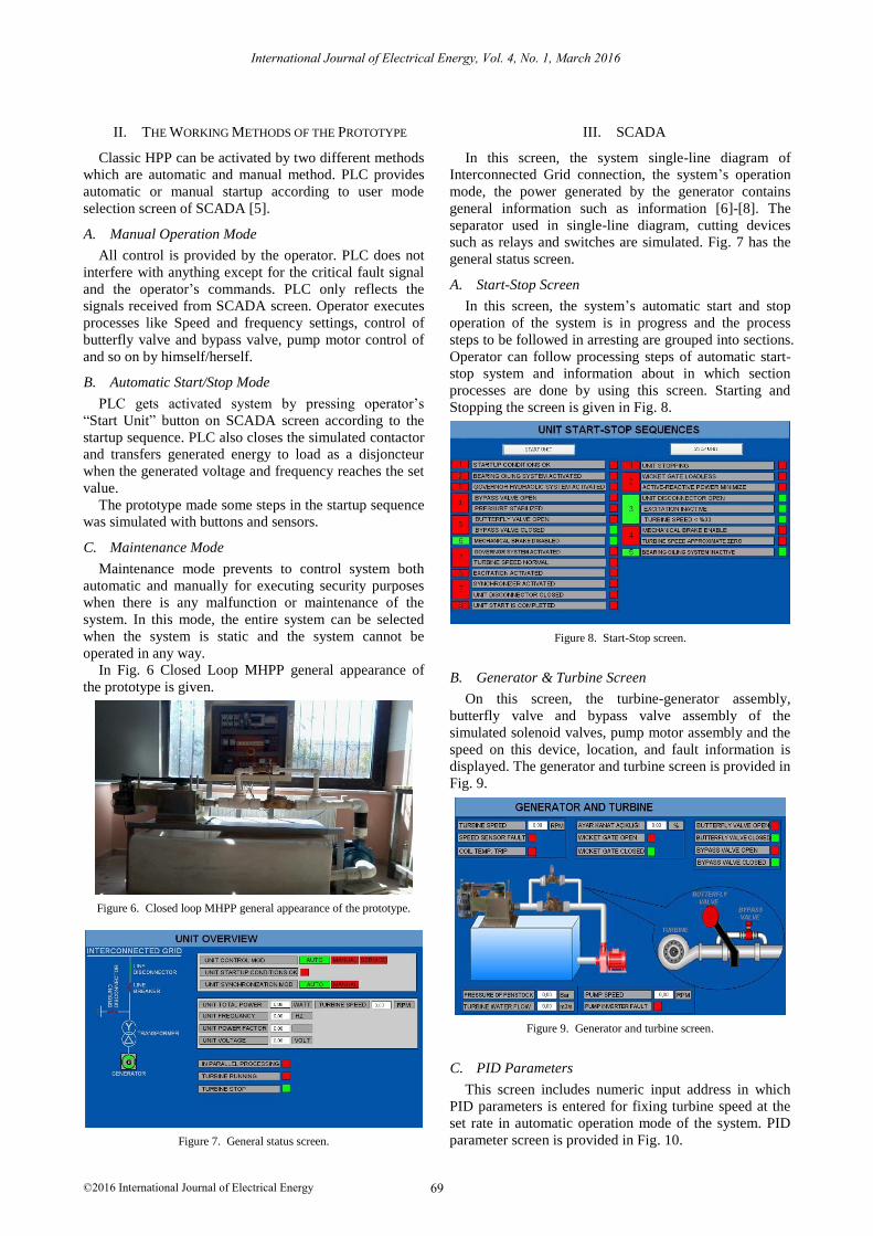
B. Electromechanical Parts
Electromechanical parts consist of Pelton turbine,
asynchronous generator and encoder [3]. These structural
parts are substantially the same as conventional
hydroelectric power plants [2].
Figure 3. Main elements of electromechanical parts for the closed loop MHPP prototype.
Water drawn from the reservoir by centrifugal pump is
transferred to Pelton turbine. Kinetic energy of water is
converted to mechanic energy by Pelton turbine [3].
Water coming from the turbine is returns to the water
tank again. Thus, a closed loop water cycle is obtained.
This mechanical energy, which is connected to the
turbine shaft belt pulley, drives the asynchronous
generator. The frequency of the asynchronous generator
output voltage is proportional to the rotational speed [4].
Therefore, for controlling the frequency generator, the
flow rate should also be controllable. For classic flow
control in hydroelectric power plants pressure hydraulic
systems are used. So water entering the turbine is
controlled by using the nozzle or wicket gate. Pelton
turbine in this developed prototype doesn’t have stage pin
hence centrifugal pump rotation was inverted for
controlling flow rate. Electromechanical parts for the
Closed Loop MHPP main elements of the prototype are
given in Fig. 3.
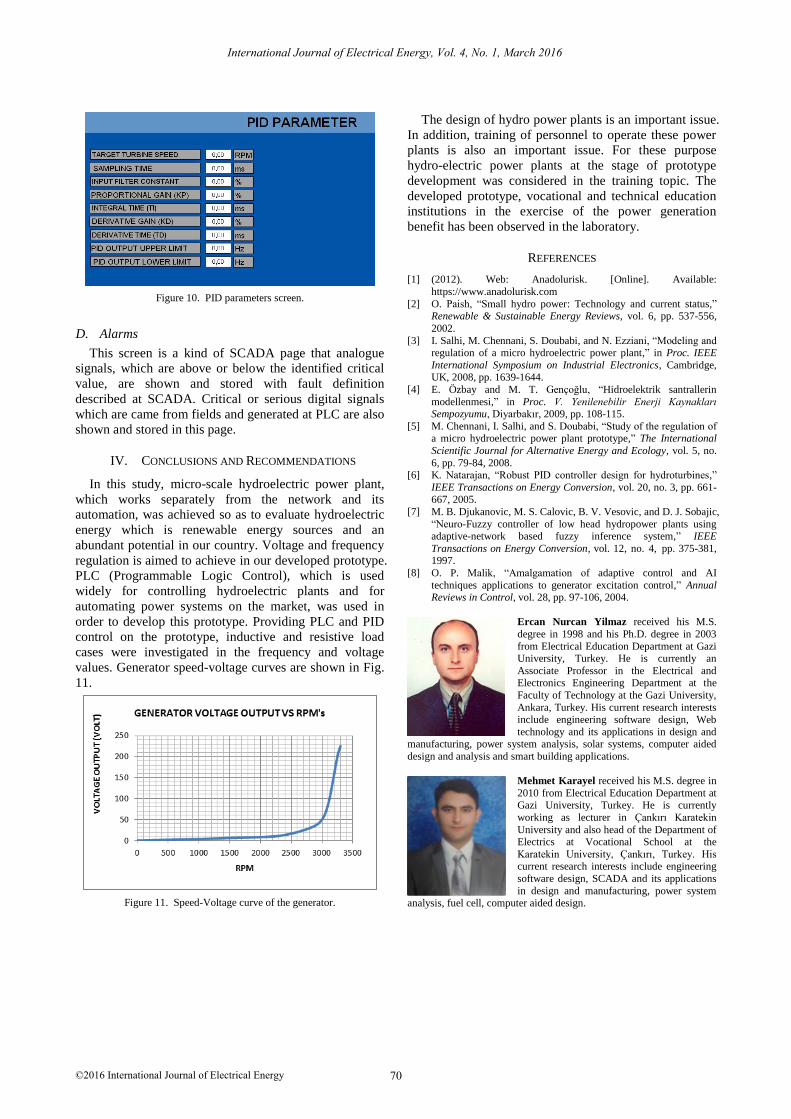
In our prototype, frequency of generator is calculated
by two different units. It can be computed firstly by using
the information of the speed meter (encoder) received by
the PLC FX3G-24MR/ES and secondly by using
ME96NS-MBA Energy Analyzer. Encoder used for
measuring the speed of the asynchronous generator
consists of inductive sensor. The sensor location observed
on the belt pulley is shown at Fig. 4.
Figure 4. Measurement system of asynchronous generator speed.
C. Controller
The system control parts are given in Fig. 5. PLC is
used for controlling MHPP, monitoring security and
failure signal. In this application, many of the possible
fault signals have been simulated by buttons and position
switches.
This prototype has two purposes. The first is for
educational purposes for students hence they can learn
HPP in the school environment in practice by using this
prototype. Second, R & D work is to provide a real
opportunity to make over simulation. Therefore, the PID
parameters is designed to be interchangeable by using
persistent data address (D1000-D1026) via the SCADA
screen. The reason for using Persistent Data addresses is
to ensure parameter values, which was entered to the
system, not to be deleted during the opening and closing
of the system.
Figure 5. The part of the system of control commands.
International Journal of Electrical Energy, Vol. 4, No. 1, March 2016
©2016 International Journal of Electrical Energy 68
II. THE WORKING METHODS OF THE PROTOTYPE
Classic HPP can be activated by two different methods
which are automatic and manual method. PLC provides
automatic or manual startup according to user mode
selection screen of SCADA [5].
A. Manual Operation Mode
All control is provided by the operator. PLC does not
interfere with anything except for the critical fault signal
and the operator’s commands. PLC only reflects the
signals received from SCADA screen. Operator executes
processes like Speed and frequency settings, control of
butterfly valve and bypass valve, pump motor control of
and so on by himself/herself.
B. Automatic Start/Stop Mode
PLC gets activated system by pressing operator’s
“Start Unit” button on SCADA screen according to the
startup sequence. PLC also closes the simulated contactor
and transfers generated energy to load as a disjoncteur
when the generated voltage and frequency reaches the set
value.
The prototype made some steps in the startup sequence
was simulated with buttons and sensors.
C. Maintenance Mode
Maintenance mode prevents to control system both
automatic and manually for executing security purposes
when there is any malfunction or maintenance of the
system. In this mode, the entire system can be selected
when the system is static and the system cannot be
operated in any way.
In Fig. 6 Closed Loop MHPP general appearance of
the prototype is given.
Figure 6. Closed loop MHPP general appearance of the prototype.
Figure 7. General status screen.
III. SCADA
In this screen, the system single-line diagram of
Interconnected Grid connection, the system’s operation
mode, the power generated by the generator contains
general information such as information [6]-[8]. The
separator used in single-line diagram, cutting devices
such as relays and switches are simulated. Fig. 7 has the
general status screen.
A. Start-Stop Screen
In this screen, the system’s automatic start and stop
operation of the system is in progress and the process
steps to be followed in arresting are grouped into sections.
Operator can follow processing steps of automatic start-
stop system and information about in which section
processes are done by using this screen. Starting and
Stopping the screen is given in Fig. 8.
Figure 8. Start-Stop screen.
B. Generator & Turbine Screen
On this screen, the turbine-generator assembly,
butterfly valve and bypass valve assembly of the
simulated solenoid valves, pump motor assembly and the
speed on this device, location, and fault information is
displayed. The generator and turbine screen is provided in
Fig. 9.
Figure 9. Generator and turbine screen.
C. PID Parameters
This screen includes numeric input address in which
PID parameters is entered for fixing turbine speed at the
set rate in automatic operation mode of the system. PID
parameter screen is provided in Fig. 10.
International Journal of Electrical Energy, Vol. 4, No. 1, March 2016
©2016 International Journal of Electrical Energy 69
Figure 10. PID parameters screen.
D. Alarms
This screen is a kind of SCADA page that analogue
signals, which are above or below the identified critical
value, are shown and stored with fault definition
described at SCADA. Critical or serious digital signals
which are came from fields and generated at PLC are also
shown and stored in this page.
IV. CONCLUSIONS AND RECOMMENDATIONS
In this study, micro-scale hydroelectric power plant,
which works separately from the network and its
automation, was achieved so as to evaluate hydroelectric
energy which is renewable energy sources and an
abundant potential in our country. Voltage and frequency
regulation is aimed to achieve in our developed prototype.
PLC (Programmable Logic Control), which is used
widely for controlling hydroelectric plants and for
automating power systems on the market, was used in
order to develop this prototype. Providing PLC and PID
control on the prototype, inductive and resistive load
cases were investigated in the frequency and voltage
values. Generator speed-voltage curves are shown in Fig.
11.
Figure 11. Speed-Voltage curve of the generator.
The design of hydro power plants is an important issue.
In addition, training of personnel to operate these power
plants is also an important issue. For these purpose
hydro-electric power plants at the stage of prototype
development was considered in the training topic. The
developed prototype, vocational and technical education
institutions in the exercise of the power generation
benefit has been observed in the laboratory.
REFERENCES
[1] (2012). Web: Anadolurisk. [Online]. Available:
https://www.anadolurisk.com
[2] O. Paish, “Small hydro power: Technology and current status,” Renewable & Sustainable Energy Reviews, vol. 6, pp. 537-556,
2002.
[3] I. Salhi, M. Chennani, S. Doubabi, and N. Ezziani, “Modeling and regulation of a micro hydroelectric power plant,” in Proc. IEEE
International Symposium on Industrial Electronics, Cambridge, UK, 2008, pp. 1639-1644.
[4] E. Özbay and M. T. Gençoğlu, “Hidroelektrik santrallerin
modellenmesi,” in Proc. V. Yenilenebilir Enerji Kaynakları Sempozyumu, Diyarbakır, 2009, pp. 108-115.
[5] M. Chennani, I. Salhi, and S. Doubabi, “Study of the regulation of a micro hydroelectric power plant prototype,” The International
Scientific Journal for Alternative Energy and Ecology, vol. 5, no.
6, pp. 79-84, 2008. [6] K. Natarajan, “Robust PID controller design for hydroturbines,”
IEEE Transactions on Energy Conversion, vol. 20, no. 3, pp. 661-667, 2005.
[7] M. B. Djukanovic, M. S. Calovic, B. V. Vesovic, and D. J. Sobajic,
“Neuro-Fuzzy controller of low head hydropower plants using adaptive-network based fuzzy inference system,” IEEE
Transactions on Energy Conversion, vol. 12 375-381, 1997.
[8] O. P. Malik, “Amalgamation of adaptive control and AI
techniques applications to generator excitation control,” Annual Reviews in Control, vol. 28, pp. 97-106, 2004.
Ercan Nurcan Yilmaz received his M.S.
degree in 1998 and his Ph.D. degree in 2003
from Electrical Education Department at Gazi University, Turkey. He is currently an
Associate Professor in the Electrical and Electronics Engineering Department at the
Faculty of Technology at the Gazi University,
Ankara, Turkey. His current research interests include engineering software design, Web
technology and its applications in design and manufacturing, power system analysis, solar systems, computer aided
design and analysis and smart building applications.
Mehmet Karayel received his M.S. degree in
2010 from Electrical Education Department at Gazi University, Turkey. He is currently
working as lecturer in Çankırı Karatekin
University and also head of the Department of Electrics at Vocational School at the
Karatekin University, Çankırı, Turkey. His current research interests include engineering
software design, SCADA and its applications
in design and manufacturing, power system analysis, fuel cell, computer aided design.
International Journal of Electrical Energy, Vol. 4, No. 1, March 2016
©2016 International Journal of Electrical Energy 70
4, pp. , no.