Page 1
INTERACTIVE
INSTALLATION AND SAFETY MANUAL
FOR TS4: SMART MODULES AND RETROFIT
CLICK TO CONTINUE It is highly recommended to
view in full screen mode
Please read these
instructions carefully
before installing
This will ensure an easy
start and a great first
customer experience with
TS4 installation
Page 2
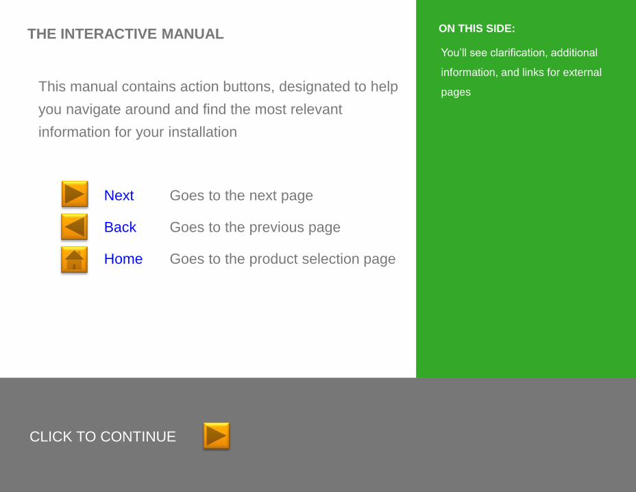
THE INTERACTIVE MANUAL
This manual contains action buttons, designated to help
you navigate around and find the most relevant
information for your installation
Next Goes to the next page
Back Goes to the previous page
Home Goes to the product selection page
CLICK TO CONTINUE
You’ll see clarification, additional
information, and links for external
pages
ON THIS SIDE:
Page 3
READ THIS FIRST
• This manual contains important instructions for installation and
maintenance of the Tigo Energy® product models TS4-L, TS4-O,
TS4-S, TS4-M, TS4-R-M, TS4-R-S, TS4-R-O, ES-GTWY-020,
Cloud Connect, Cloud Connect Advanced and related Tigo Energy
software applications.
• Risk of electric shock, do not remove cover, disassemble, or repair,
no user serviceable parts inside. Refer servicing to qualified
service personnel.
• Before installing or using the Tigo Energy® System, please read all
instructions and warning markings on the Tigo Energy products,
appropriate sections of your inverter manual, photovoltaic (PV)
module installation manual, and other available safety guides.
• Failure to adhere to these instructions may result in injury or death,
damage to the system or voiding the factory warranty.
• To reduce risk of fire and shock hazard, install this device with
strict adherence to National Electric Code (NEC) ANSI/NFPA 70
and/or local electrical codes. When the photovoltaic array is
exposed to light, it supplies a DC voltage to the Tigo Energy®
Module Maximizer™. The Module Maximizers and Smart Modules
start in the “ON” state and their output voltage may be as high as
the PV module open circuit voltage (Voc) when connected to the
module. The installer should use the same caution when handling
electrical cables from a PV module with or without the Tigo Energy
Module Maximizer attached.
• Installation must be performed by trained professionals only. Tigo
Energy does not assume liability for loss or damage resulting from
improper handling, installation, or misuse of products.
• Remove all metallic jewelry prior to installing the Tigo Energy
Module Maximizers or Smart Modules to reduce the risk of
contacting live circuitry. Do not attempt to install in inclement
weather.
• Do not operate the Tigo Energy Module Maximizers or Smart
Modules if they have been physically damaged. Check existing
cables and connectors, ensuring they are in good condition and
appropriate in rating. Do not operate Tigo Energy Module
Maximizers or Smart Modules with damaged or substandard wiring
or connectors. Tigo Energy Module Maximizers must be mounted
on the high end of the PV module back-sheet or racking system,
and in any case above ground.
• Do not connect or disconnect under load. Turning off the Inverter
and/or the Tigo Energy products may not reduce this risk. Internal
capacitors within the inverter can remain charged for several
minutes after disconnecting all power sources. Verify capacitors
have discharged by measuring voltage across inverter terminals
prior to disconnecting wiring if service is required.
• Service Personnel: Check the voltage of the array after activating
the Tigo Energy® PV-Safe™ function on the MMU prior to
performing service.
• Always assume Module Maximizers and Smart Modules are in
“ON” state, or may turn on when restarting.
IMPORTANT SAFETY INSTRUCTIONS
SAVE THESE INSTRUCTIONS
LETHAL VOLTAGE MAY BE PRESENT IN ANY PV INSTALLATION
Page 4
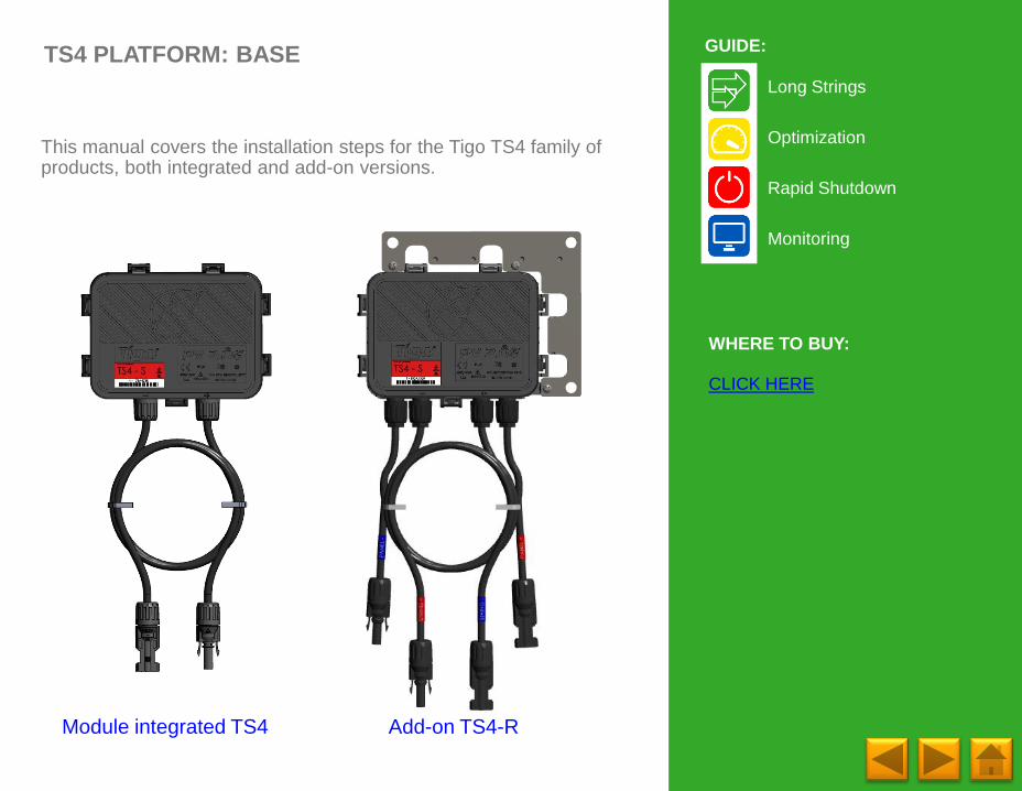
TS4 PLATFORM: BASE
This manual covers the installation steps for the Tigo TS4 family of products, both integrated and add-on versions.
Long Strings
Optimization
Rapid Shutdown
Monitoring
GUIDE:
WHERE TO BUY:
CLICK HERE
Module integrated TS4 Add-on TS4-R
Page 5
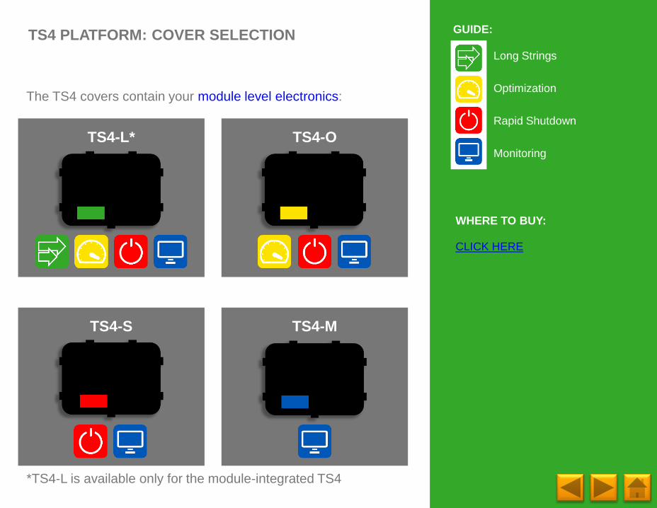
TS4 PLATFORM: COVER SELECTION
The TS4 covers contain your module level electronics:
TS4-L*
Long Strings
Optimization
Rapid Shutdown
Monitoring
GUIDE:
WHERE TO BUY:
CLICK HERE
TS4-O
TS4-S TS4-M
*TS4-L is available only for the module-integrated TS4
Page 6
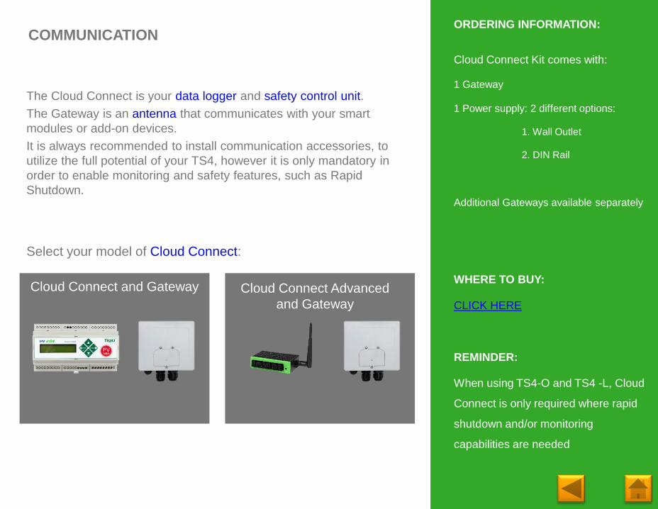
COMMUNICATION
Cloud Connect Kit comes with:
1 Gateway
1 Power supply: 2 different options:
1. Wall Outlet
2. DIN Rail
Additional Gateways available separately
WHERE TO BUY:
CLICK HERE
REMINDER:
When using TS4-O and TS4 -L, Cloud
Connect is only required where rapid
shutdown and/or monitoring
capabilities are needed
ORDERING INFORMATION:
Cloud Connect and Gateway
The Cloud Connect is your data logger and safety control unit.
The Gateway is an antenna that communicates with your smart
modules or add-on devices.
It is always recommended to install communication accessories, to
utilize the full potential of your TS4, however it is only mandatory in
order to enable monitoring and safety features, such as Rapid
Shutdown.
Cloud Connect Advanced
and Gateway
Select your model of Cloud Connect:
Page 7
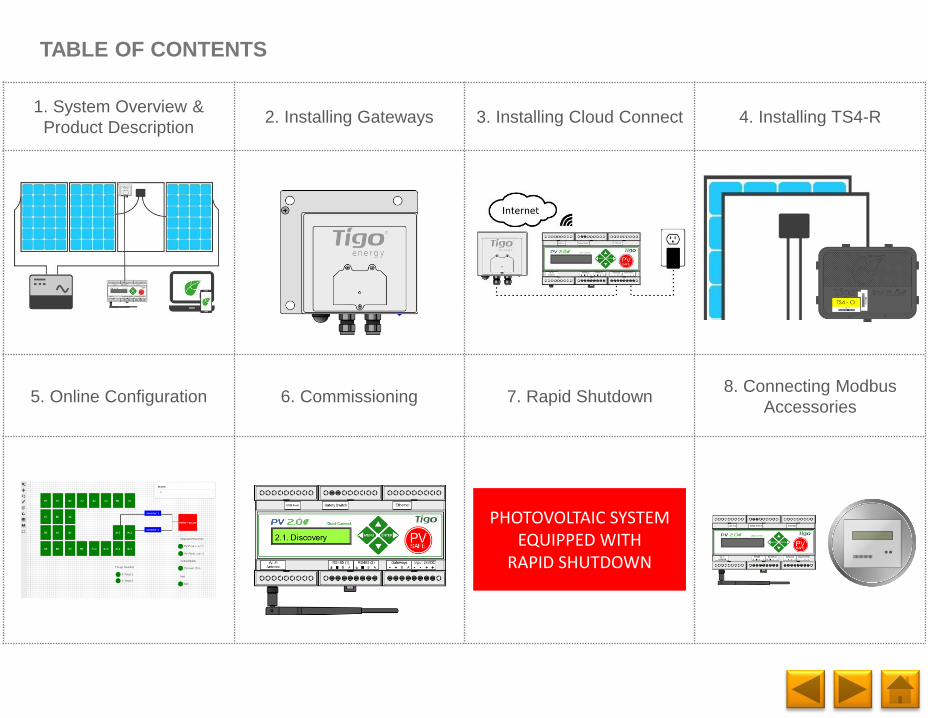
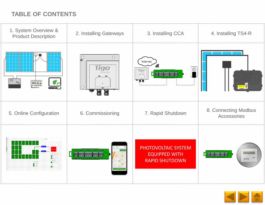
1. System Overview &
Product Description2. Installing Gateways 3. Installing Cloud Connect 4. Installing TS4-R
5. Online Configuration 6. Commissioning 7. Rapid Shutdown8. Connecting Modbus
Accessories
TABLE OF CONTENTS
PHOTOVOLTAIC SYSTEM EQUIPPED WITH
RAPID SHUTDOWN
Page 8
Internet
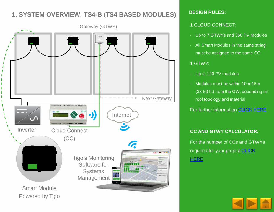
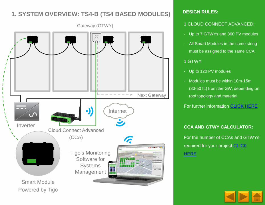
1. SYSTEM OVERVIEW: TS4-B (TS4 BASED MODULES)
1 CLOUD CONNECT:
- Up to 7 GTWYs and 360 PV modules
- All Smart Modules in the same string
must be assigned to the same CC
1 GTWY:
- Up to 120 PV modules
- Modules must be within 10m-15m
(33-50 ft.) from the GW, depending on
roof topology and material
For further information CLICK HERE
CC AND GTWY CALCULATOR:
For the number of CCs and GTWYs
required for your project CLICK
HERE
DESIGN RULES:
Inverter
Smart Module
Powered by Tigo
Tigo’s Monitoring
Software for
Systems
Management
Gateway (GTWY)
Cloud Connect
(CC)
Next Gateway
Page 9
Internet
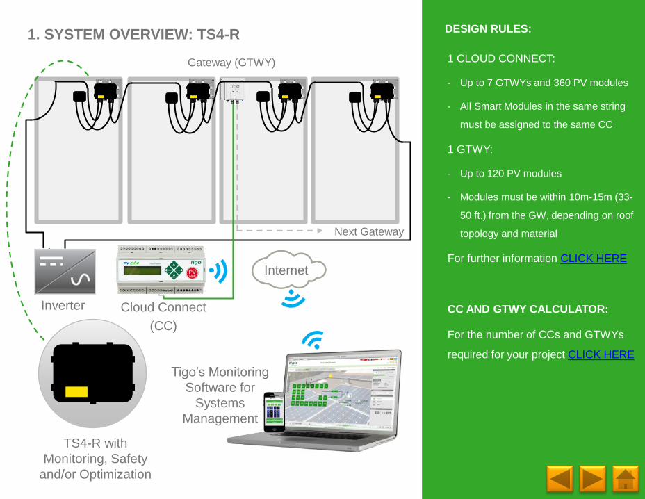
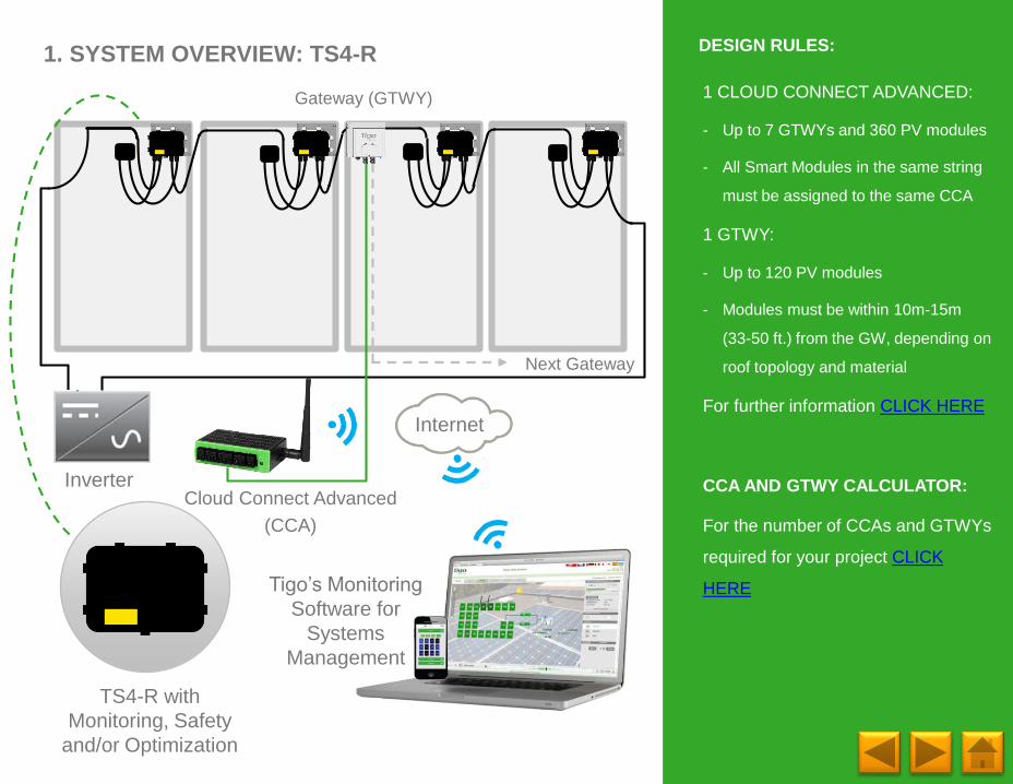
1. SYSTEM OVERVIEW: TS4-R
1 CLOUD CONNECT:
- Up to 7 GTWYs and 360 PV modules
- All Smart Modules in the same string
must be assigned to the same CC
1 GTWY:
- Up to 120 PV modules
- Modules must be within 10m-15m (33-
50 ft.) from the GW, depending on roof
topology and material
For further information CLICK HERE
CC AND GTWY CALCULATOR:
For the number of CCs and GTWYs
required for your project CLICK HERE
DESIGN RULES:
Inverter
TS4-R with
Monitoring, Safety
and/or Optimization
Tigo’s Monitoring
Software for
Systems
Management
Gateway (GTWY)
Cloud Connect
(CC)
Next Gateway
Page 10
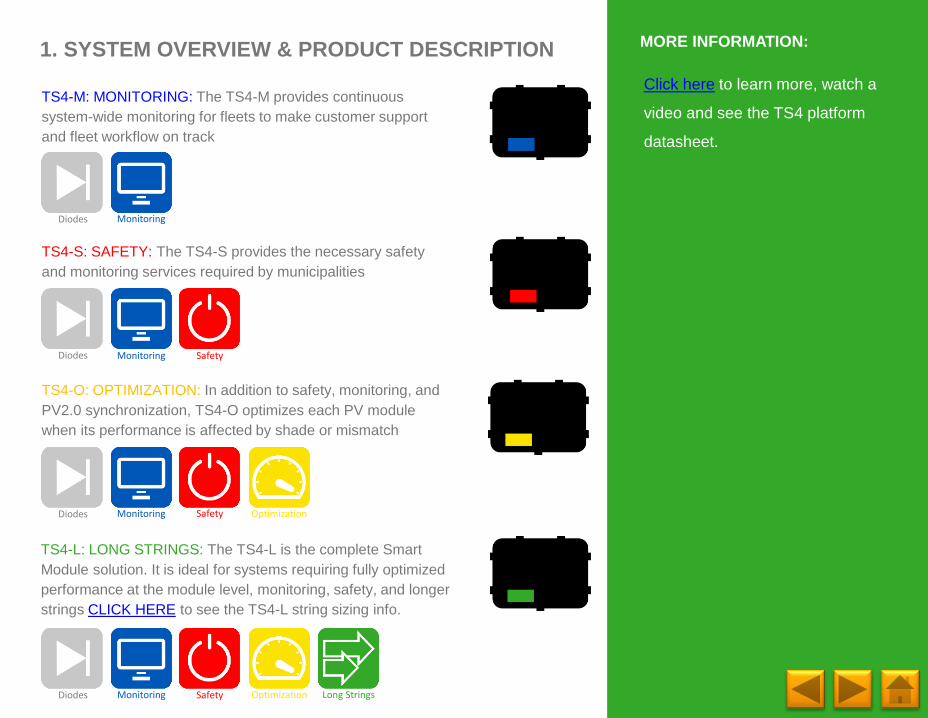
TS4-O: OPTIMIZATION: In addition to safety, monitoring, and
PV2.0 synchronization, TS4-O optimizes each PV module
when its performance is affected by shade or mismatch
TS4-S: SAFETY: The TS4-S provides the necessary safety
and monitoring services required by municipalities
TS4-L: LONG STRINGS: The TS4-L is the complete Smart
Module solution. It is ideal for systems requiring fully optimized
performance at the module level, monitoring, safety, and longer
strings CLICK HERE to see the TS4-L string sizing info.
1. SYSTEM OVERVIEW & PRODUCT DESCRIPTION
TS4-M: MONITORING: The TS4-M provides continuous
system-wide monitoring for fleets to make customer support
and fleet workflow on track
Diodes Monitoring Safety Optimization
Diodes Monitoring Safety
Diodes Monitoring
Diodes Monitoring Safety Optimization Long Strings
Click here to learn more, watch a
video and see the TS4 platform
datasheet.
MORE INFORMATION:
Page 11
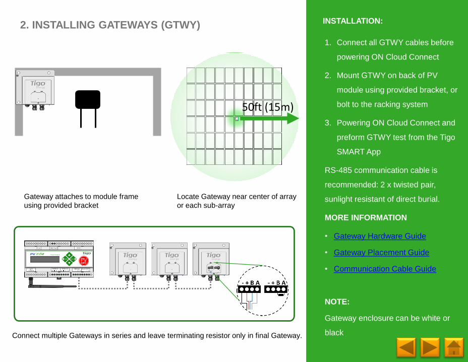
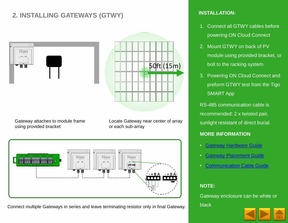
Connect multiple Gateways in series and leave terminating resistor only in final Gateway.
2. INSTALLING GATEWAYS (GTWY)
Locate Gateway near center of array
or each sub-array
Gateway attaches to module frame
using provided bracket
50ft (15m)
1. Connect all GTWY cables before
powering ON Cloud Connect
2. Mount GTWY on back of PV
module using provided bracket, or
bolt to the racking system
3. Powering ON Cloud Connect and
preform GTWY test from the Tigo
SMART App
RS-485 communication cable is
recommended: 2 x twisted pair,
sunlight resistant of direct burial.
MORE INFORMATION
• Gateway Hardware Guide
• Gateway Placement Guide
• Communication Cable Guide
NOTE:
Gateway enclosure can be white or
black
INSTALLATION:
Page 12
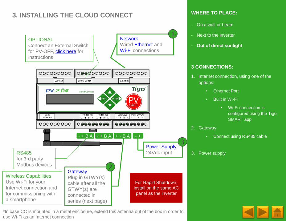
3. INSTALLING THE CLOUD CONNECT
- On a wall or beam
- Next to the inverter
- Out of direct sunlight
3 CONNECTIONS:
1. Internet connection, using one of the
options:
• Ethernet Port
• Built in Wi-Fi
• Wi-Fi connection is
configured using the Tigo
SMART app
2. Gateway
• Connect using RS485 cable
3. Power supply
OPTIONAL
Connect an External Switch
for PV-OFF, click here for
instructions
Network
Wired Ethernet and
Wi-Fi connections
Wireless Capabilities
Use Wi-Fi for your
Internet connection and
for commissioning with
a smartphone
1
Power Supply
24Vdc input
*In case CC is mounted in a metal enclosure, extend this antenna out of the box in order to
use Wi-Fi as an Internet connection
3
Gateway
Plug in GTWY(s)
cable after all the
GTWY(s) are
connected in
series (next page)
2
- +- + B A + - B A
RS485
for 3rd party
Modbus devices
- + B A
WHERE TO PLACE:
For Rapid Shutdown,
install on the same AC
panel as the inverter
Page 13
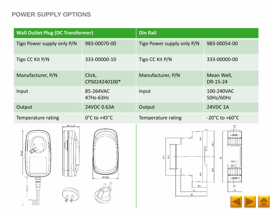
POWER SUPPLY OPTIONS
Wall Outlet Plug (DC Transformer) Din Rail
Tigo Power supply only P/N 983‐00070-00 Tigo Power supply only P/N 983‐00054-00
Tigo CC Kit P/N 333‐00000-10 Tigo CC Kit P/N 333‐00000-00
Manufacturer, P/N Click, CPS024240100*
Manufacturer, P/N Mean Well, DR-15-24
Input 85-264VAC 47Hz-63Hz
Input 100-240VAC 50Hz/60Hz
Output 24VDC 0.63A Output 24VDC 1A
Temperature rating 0°C to +45°C Temperature rating -20°C to +60°C
Page 14
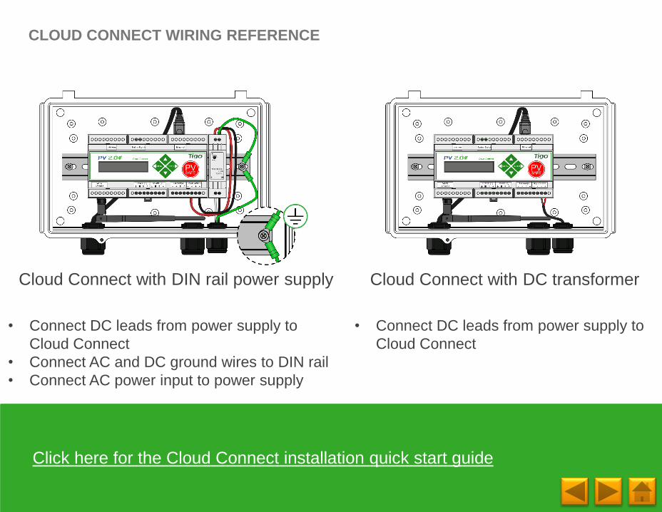
CLOUD CONNECT WIRING REFERENCE
Cloud Connect with DC transformerCloud Connect with DIN rail power supply
• Connect DC leads from power supply to
Cloud Connect
• Connect AC and DC ground wires to DIN rail
• Connect AC power input to power supply
• Connect DC leads from power supply to
Cloud Connect
Click here for the Cloud Connect installation quick start guide
Page 15
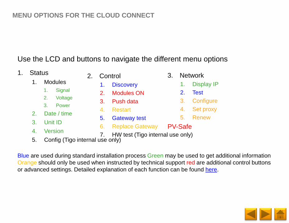
MENU OPTIONS FOR THE CLOUD CONNECT
1. Status
1. Modules
1. Signal
2. Voltage
3. Power
2. Date / time
3. Unit ID
4. Version
5. Config (Tigo internal use only)
Use the LCD and buttons to navigate the different menu options
Blue are used during standard installation process Green may be used to get additional information
Orange should only be used when instructed by technical support red are additional control buttons
or advanced settings. Detailed explanation of each function can be found here.
2. Control
1. Discovery
2. Modules ON
3. Push data
4. Restart
5. Gateway test
6. Replace Gateway
7. HW test (Tigo internal use only)
3. Network
1. Display IP
2. Test
3. Configure
4. Set proxy
5. Renew
PV-Safe
Page 16
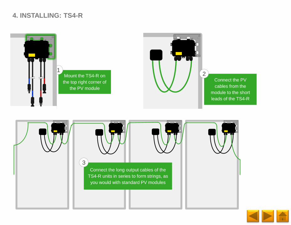
4. INSTALLING: TS4-R
Mount the TS4-R on
the top right corner of
the PV module
1
Connect the long output cables of the
TS4-R units in series to form strings, as
you would with standard PV modules
3
Connect the PV
cables from the
module to the short
leads of the TS4-R
2
Page 17
1. System Overview &
Product Description2. Installing Gateways 3. Installing CCA 4. Installing TS4-R
5. Online Configuration 6. Commissioning 7. Rapid Shutdown8. Connecting Modbus
Accessories
TABLE OF CONTENTS
PHOTOVOLTAIC SYSTEM EQUIPPED WITH
RAPID SHUTDOWN
Page 18
Internet
1. SYSTEM OVERVIEW: TS4-B (TS4 BASED MODULES)
1 CLOUD CONNECT ADVANCED:
- Up to 7 GTWYs and 360 PV modules
- All Smart Modules in the same string
must be assigned to the same CCA
1 GTWY:
- Up to 120 PV modules
- Modules must be within 10m-15m
(33-50 ft.) from the GW, depending on
roof topology and material
For further information CLICK HERE
CCA AND GTWY CALCULATOR:
For the number of CCAs and GTWYs
required for your project CLICK
HERE
DESIGN RULES:
Inverter
Smart Module
Powered by Tigo
Tigo’s Monitoring
Software for
Systems
Management
Gateway (GTWY)
Cloud Connect Advanced
(CCA)
Next Gateway
Page 19
Gateway (GTWY)
Internet
1. SYSTEM OVERVIEW: TS4-R
1 CLOUD CONNECT ADVANCED:
- Up to 7 GTWYs and 360 PV modules
- All Smart Modules in the same string
must be assigned to the same CCA
1 GTWY:
- Up to 120 PV modules
- Modules must be within 10m-15m
(33-50 ft.) from the GW, depending on
roof topology and material
For further information CLICK HERE
CCA AND GTWY CALCULATOR:
For the number of CCAs and GTWYs
required for your project CLICK
HERE
DESIGN RULES:
Inverter
TS4-R with
Monitoring, Safety
and/or Optimization
Tigo’s Monitoring
Software for
Systems
Management
Next Gateway
Cloud Connect Advanced
(CCA)
Page 20
TS4-O: OPTIMIZATION: In addition to safety, monitoring, and
PV2.0 synchronization, TS4-O optimizes each PV module
when its performance is affected by shade or mismatch
TS4-S: SAFETY: The TS4-S provides the necessary safety
and monitoring services required by municipalities
TS4-L: LONG STRINGS: The TS4-L is the complete Smart
Module solution. It is ideal for systems requiring fully optimized
performance at the module level, monitoring, safety, and longer
strings CLICK HERE to see the TS4-L string sizing info.
1. SYSTEM OVERVIEW & PRODUCT DESCRIPTION
TS4-M: MONITORING: The TS4-M provides continuous
system-wide monitoring for fleets to make customer support
and fleet workflow on track
Diodes Monitoring Safety Optimization
Diodes Monitoring Safety
Diodes Monitoring
Diodes Monitoring Safety Optimization Long Strings
Click here to learn more, watch a
video and see the TS4 platform
datasheet.
MORE INFORMATION:
Page 21
Connect multiple Gateways in series and leave terminating resistor only in final Gateway.
2. INSTALLING GATEWAYS (GTWY)
Locate Gateway near center of array
or each sub-array
Gateway attaches to module frame
using provided bracket
50ft (15m)
1. Connect all GTWY cables before
powering ON Cloud Connect
2. Mount GTWY on back of PV
module using provided bracket, or
bolt to the racking system
3. Powering ON Cloud Connect and
preform GTWY test from the Tigo
SMART App
RS-485 communication cable is
recommended: 2 x twisted pair,
sunlight resistant of direct burial.
MORE INFORMATION
• Gateway Hardware Guide
• Gateway Placement Guide
• Communication Cable Guide
NOTE:
Gateway enclosure can be white or
black
INSTALLATION:
Page 22
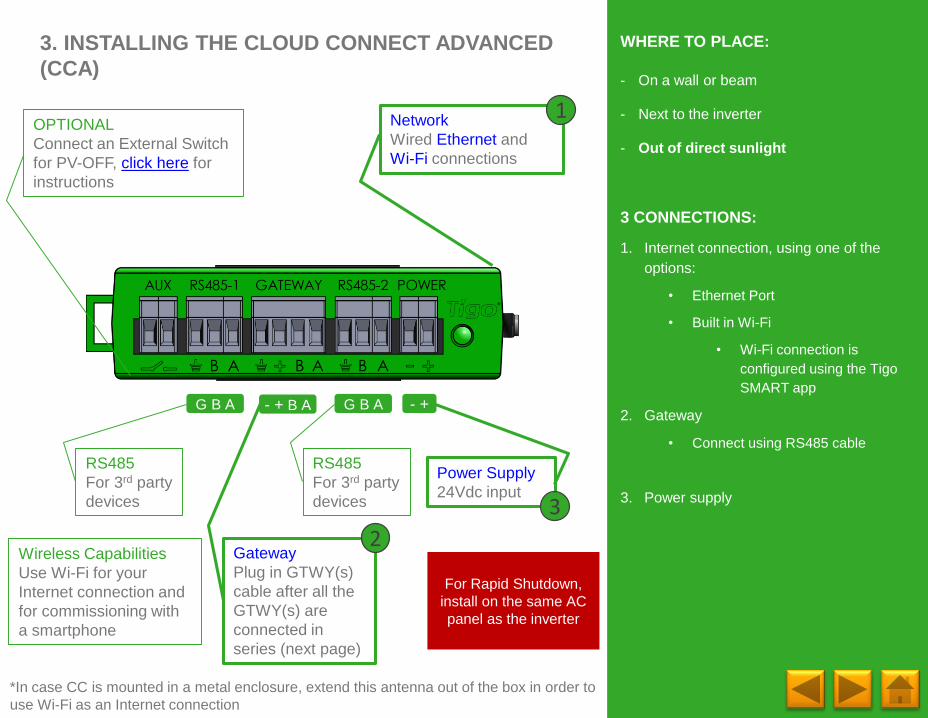
3. INSTALLING THE CLOUD CONNECT ADVANCED
(CCA)
OPTIONAL
Connect an External Switch
for PV-OFF, click here for
instructions
Network
Wired Ethernet and
Wi-Fi connections
Wireless Capabilities
Use Wi-Fi for your
Internet connection and
for commissioning with
a smartphone
1
Power Supply
24Vdc input
*In case CC is mounted in a metal enclosure, extend this antenna out of the box in order to
use Wi-Fi as an Internet connection
3
Gateway
Plug in GTWY(s)
cable after all the
GTWY(s) are
connected in
series (next page)
2
For Rapid Shutdown,
install on the same AC
panel as the inverter
- +
RS485
For 3rd party
devices
G B A - + B A G B A
RS485
For 3rd party
devices
- On a wall or beam
- Next to the inverter
- Out of direct sunlight
3 CONNECTIONS:
1. Internet connection, using one of the
options:
• Ethernet Port
• Built in Wi-Fi
• Wi-Fi connection is
configured using the Tigo
SMART app
2. Gateway
• Connect using RS485 cable
3. Power supply
WHERE TO PLACE:
Page 23
POWER SUPPLY OPTIONS
Wall Outlet Plug (DC Transformer) Din Rail
Tigo Power supply only P/N 983‐00070-00 Tigo Power supply only P/N 983‐00054-00
Tigo CC Kit P/N 333‐00000-10 Tigo CC Kit P/N 333‐00000-00
Manufacturer, P/N Click, CPS024240100*
Manufacturer, P/N Mean Well, DR-15-24
Input 85-264VAC 47Hz-63Hz
Input 100-240VAC 50Hz/60Hz
Output 24VDC 0.63A Output 24VDC 1A
Temperature rating 0°C to +45°C Temperature rating -20°C to +60°C
Page 24
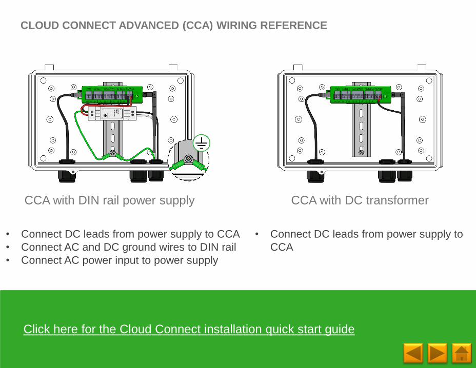
CLOUD CONNECT ADVANCED (CCA) WIRING REFERENCE
• Connect DC leads from power supply to CCA
• Connect AC and DC ground wires to DIN rail
• Connect AC power input to power supply
• Connect DC leads from power supply to
CCA
Click here for the Cloud Connect installation quick start guide
CCA with DC transformerCCA with DIN rail power supply
Page 25
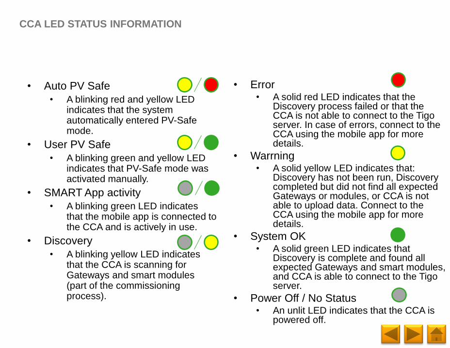
CCA LED STATUS INFORMATION
• Auto PV Safe
• A blinking red and yellow LED indicates that the system automatically entered PV-Safe mode.
• User PV Safe
• A blinking green and yellow LED indicates that PV-Safe mode was activated manually.
• SMART App activity
• A blinking green LED indicates that the mobile app is connected to the CCA and is actively in use.
• Discovery
• A blinking yellow LED indicates that the CCA is scanning for Gateways and smart modules (part of the commissioning process).
• Error• A solid red LED indicates that the
Discovery process failed or that the CCA is not able to connect to the Tigo server. In case of errors, connect to the CCA using the mobile app for more details.
• Warrning• A solid yellow LED indicates that:
Discovery has not been run, Discovery completed but did not find all expected Gateways or modules, or CCA is not able to upload data. Connect to the CCA using the mobile app for more details.
• System OK• A solid green LED indicates that
Discovery is complete and found all expected Gateways and smart modules, and CCA is able to connect to the Tigo server.
• Power Off / No Status• An unlit LED indicates that the CCA is
powered off.
Page 26
4. INSTALLING: TS4-R
Mount the TS4-R on
the top right corner of
the PV module
1
Connect the long output cables of the
TS4-R units in series to form strings, as
you would with standard PV modules
3
Connect the PV
cables from the
module to the short
leads of the TS4-R
2
Page 27
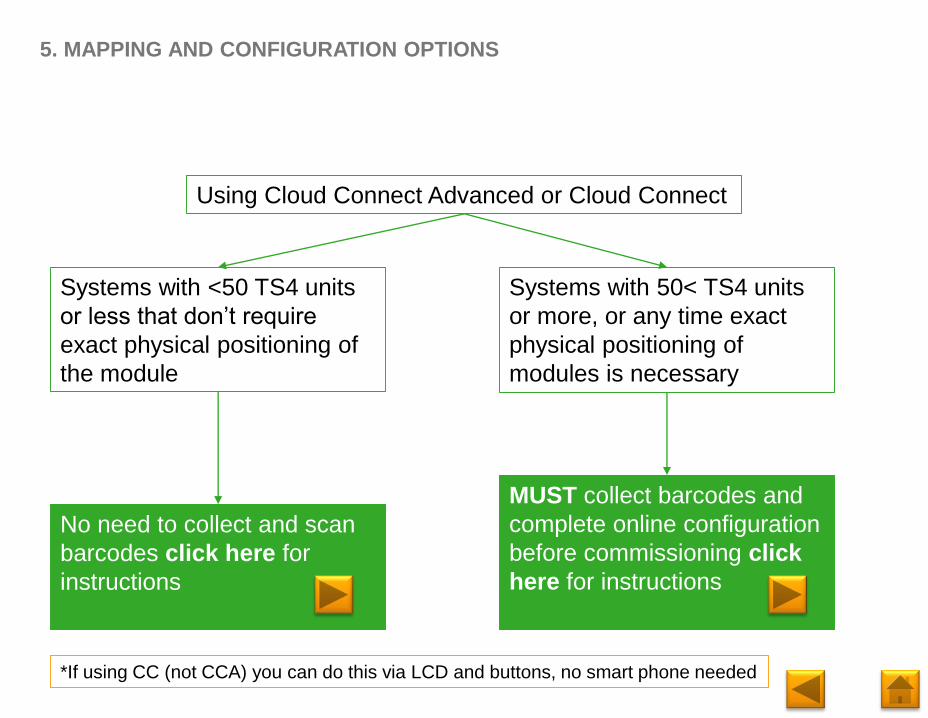
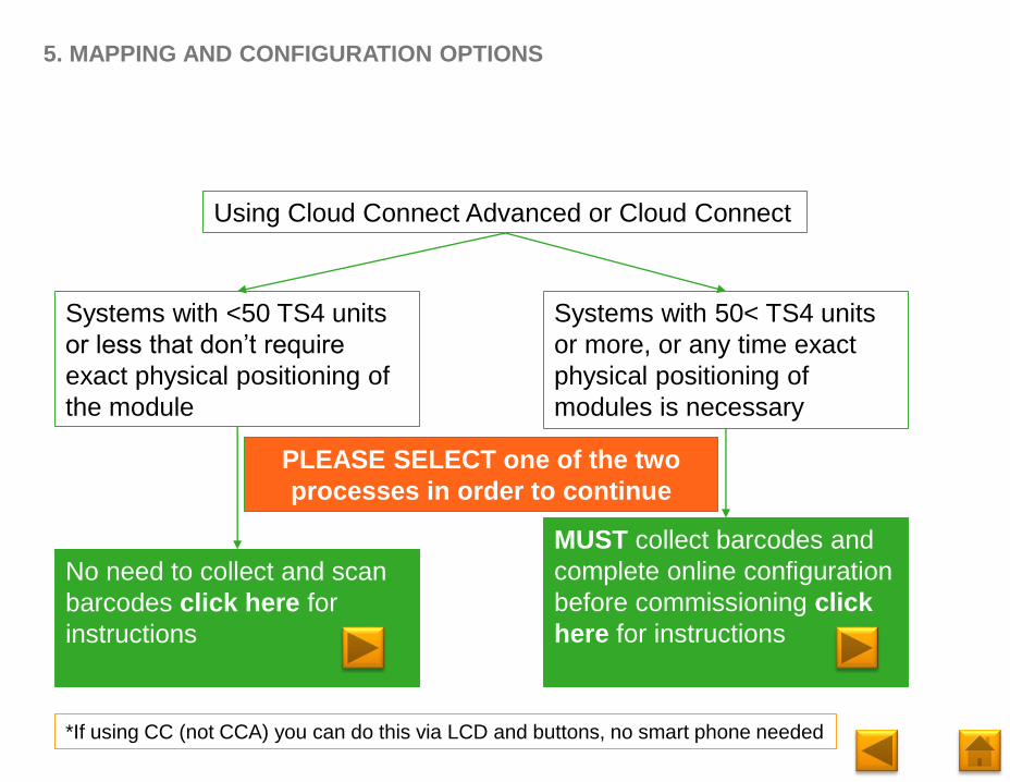
5. MAPPING AND CONFIGURATION OPTIONS
Using Cloud Connect Advanced or Cloud Connect
Systems with <50 TS4 units
or less that don’t require
exact physical positioning of
the module
No need to collect and scan
barcodes click here for
instructions
Systems with 50< TS4 units
or more, or any time exact
physical positioning of
modules is necessary
MUST collect barcodes and
complete online configuration
before commissioning click
here for instructions
*If using CC (not CCA) you can do this via LCD and buttons, no smart phone needed
Page 28
5. MAPPING AND CONFIGURATION OPTIONS
Using Cloud Connect Advanced or Cloud Connect
Systems with <50 TS4 units
or less that don’t require
exact physical positioning of
the module
No need to collect and scan
barcodes click here for
instructions
Systems with 50< TS4 units
or more, or any time exact
physical positioning of
modules is necessary
MUST collect barcodes and
complete online configuration
before commissioning click
here for instructions
*If using CC (not CCA) you can do this via LCD and buttons, no smart phone needed
PLEASE SELECT one of the two
processes in order to continue
Page 29
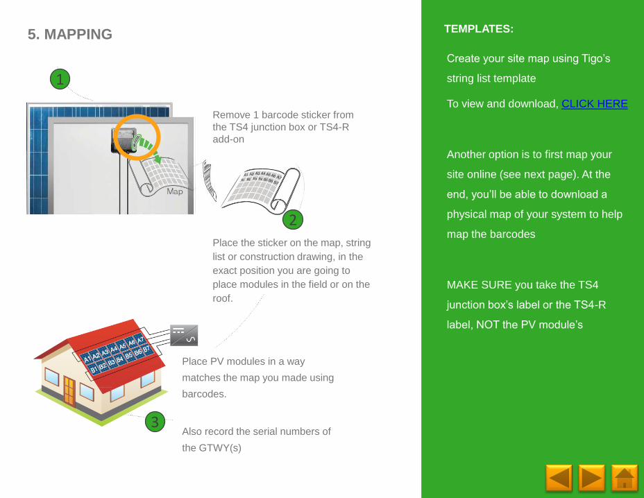
Place the sticker on the map, string
list or construction drawing, in the
exact position you are going to
place modules in the field or on the
roof.
5. MAPPING
Remove 1 barcode sticker from
the TS4 junction box or TS4-R
add-on
Create your site map using Tigo’s
string list template
To view and download, CLICK HERE
Another option is to first map your
site online (see next page). At the
end, you’ll be able to download a
physical map of your system to help
map the barcodes
MAKE SURE you take the TS4
junction box’s label or the TS4-R
label, NOT the PV module’s
TEMPLATES:
Place PV modules in a way
matches the map you made using
barcodes.
Also record the serial numbers of
the GTWY(s)
1
2
3
Page 30
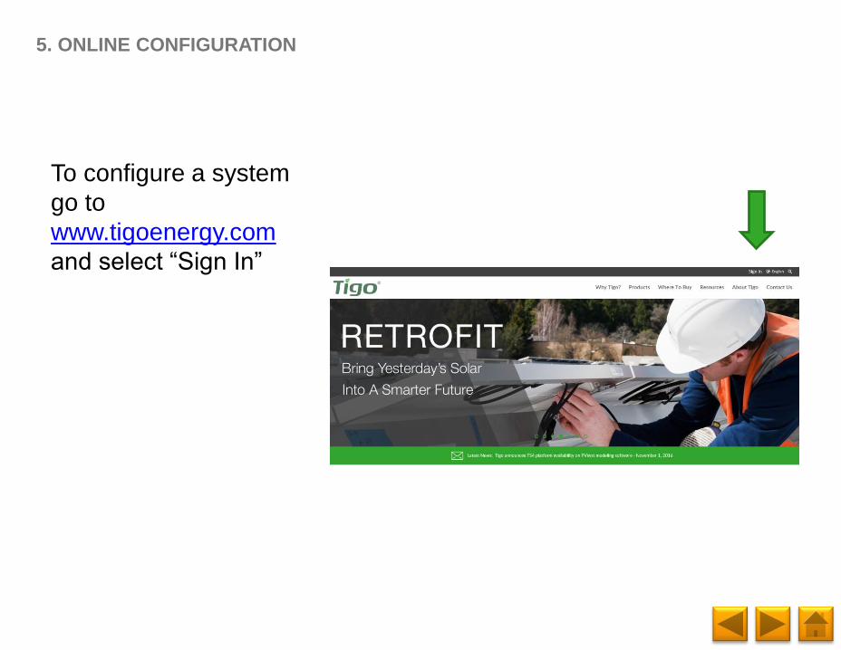
To configure a system
go to
www.tigoenergy.com
and select “Sign In”
5. ONLINE CONFIGURATION
Page 31
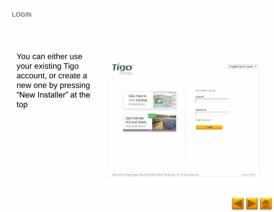
You can either use
your existing Tigo
account, or create a
new one by pressing
“New Installer” at the
top
LOGIN
Page 32
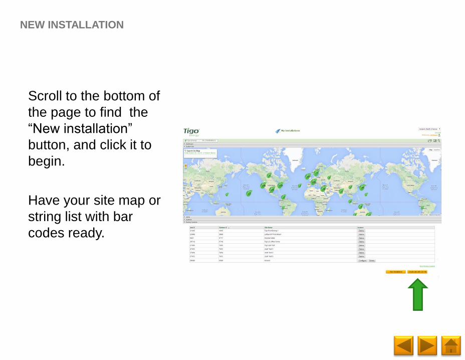
Scroll to the bottom of
the page to find the
“New installation”
button, and click it to
begin.
Have your site map or
string list with bar
codes ready.
NEW INSTALLATION
Page 33
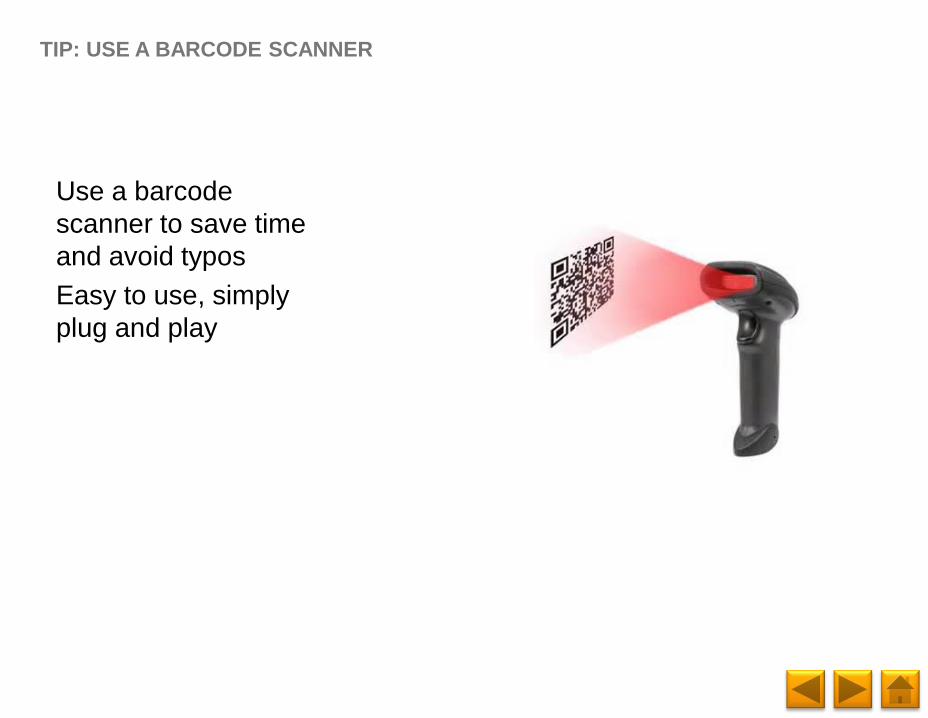
Use a barcode
scanner to save time
and avoid typos
Easy to use, simply
plug and play
TIP: USE A BARCODE SCANNER
Page 34
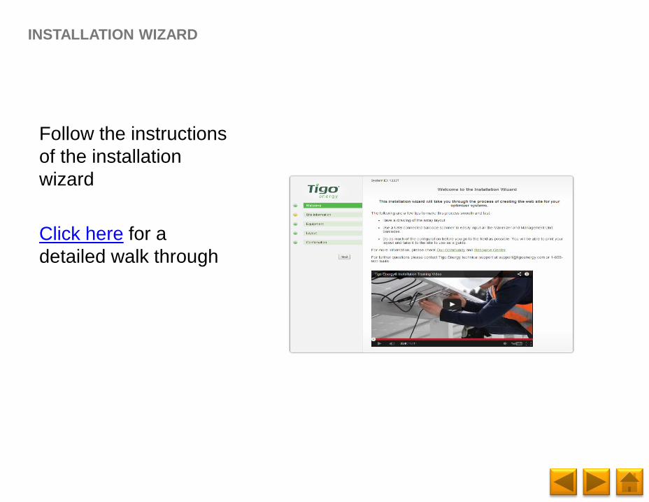
Follow the instructions
of the installation
wizard
Click here for a
detailed walk through
INSTALLATION WIZARD
Page 35
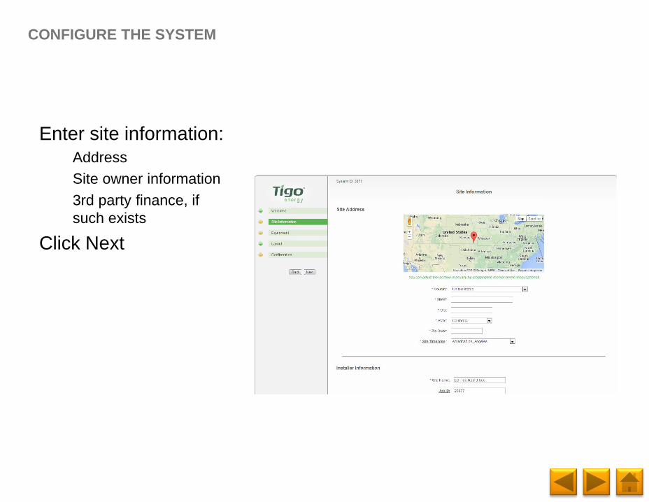
Enter site information:
Address
Site owner information
3rd party finance, if
such exists
Click Next
CONFIGURE THE SYSTEM
Page 36
Enter inverter
information
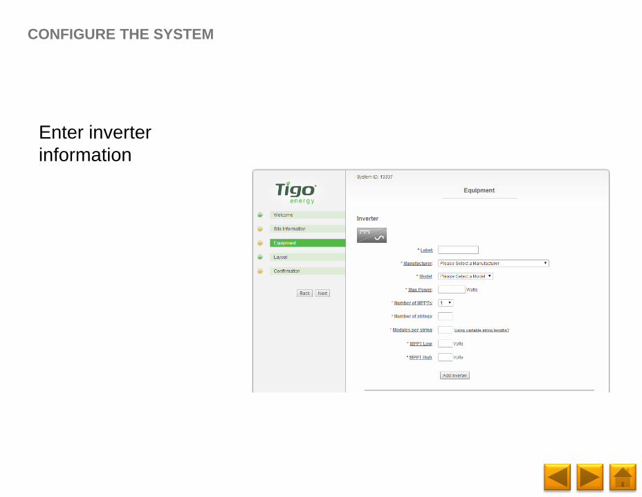
CONFIGURE THE SYSTEM
Page 37
Enter inverter
information
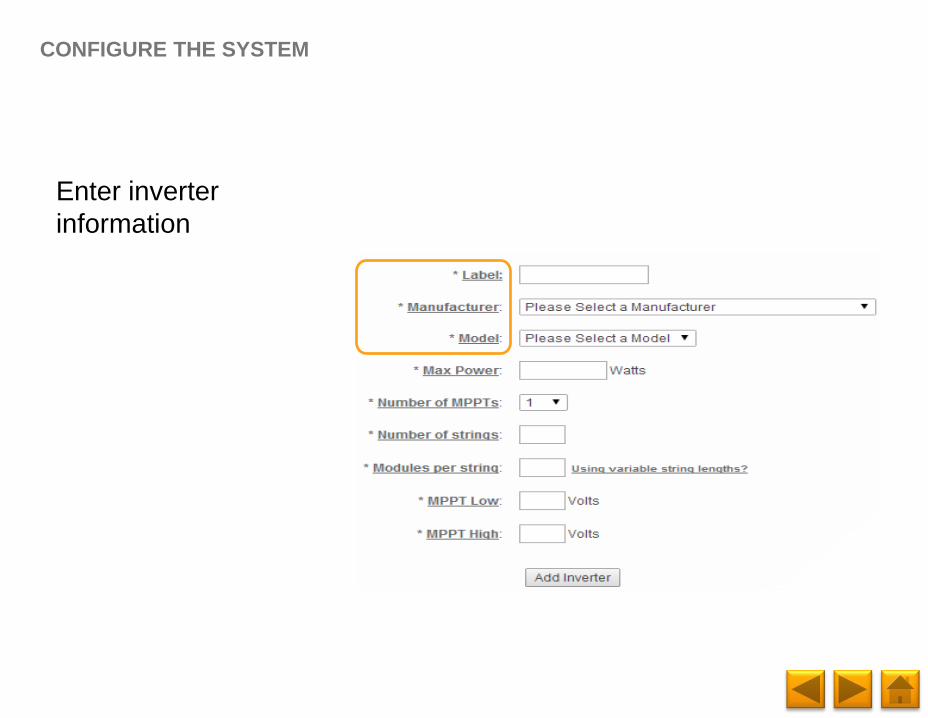
CONFIGURE THE SYSTEM
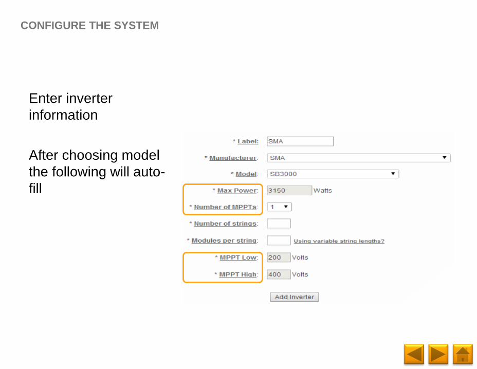
Page 38
Enter inverter
information
After choosing model
the following will auto-
fill
CONFIGURE THE SYSTEM
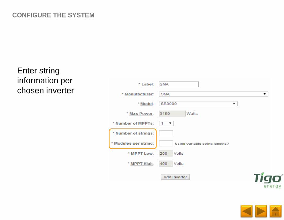
Page 39
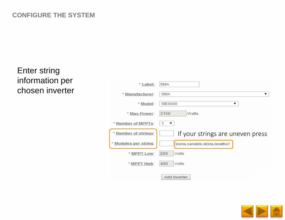
Enter string
information per
chosen inverter
CONFIGURE THE SYSTEM
Page 40
Enter string
information per
chosen inverter
CONFIGURE THE SYSTEM
If your strings are uneven press
Page 41
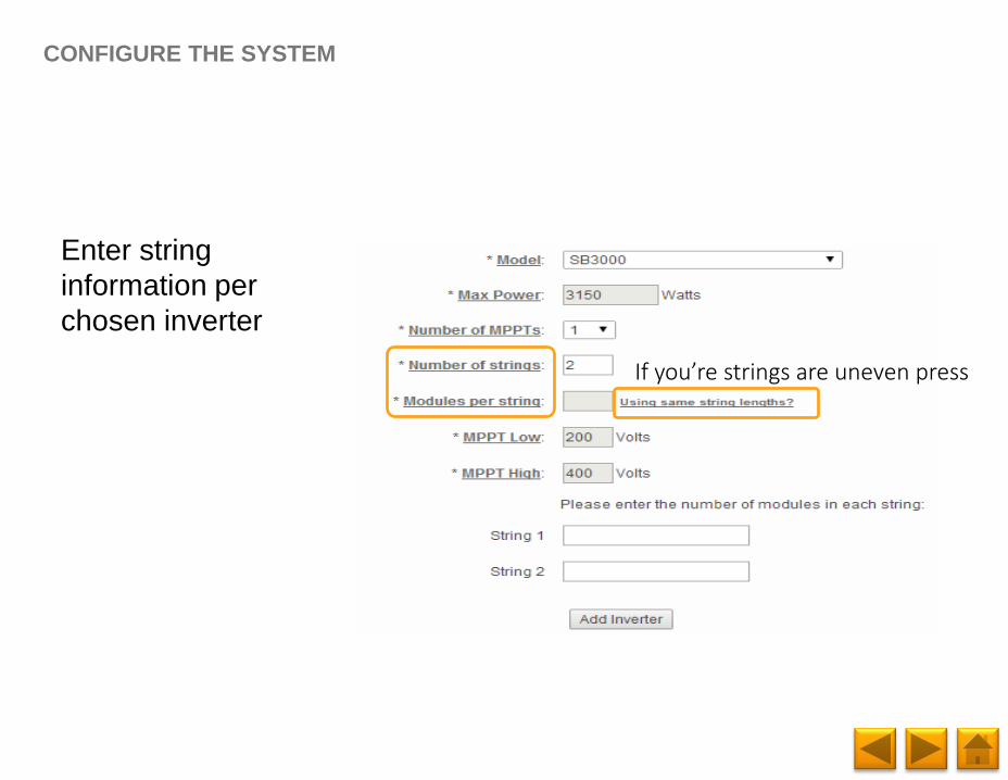
Enter string
information per
chosen inverter
CONFIGURE THE SYSTEM
If you’re strings are uneven press
Page 42
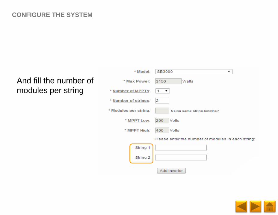
And fill the number of
modules per string
CONFIGURE THE SYSTEM
Page 43
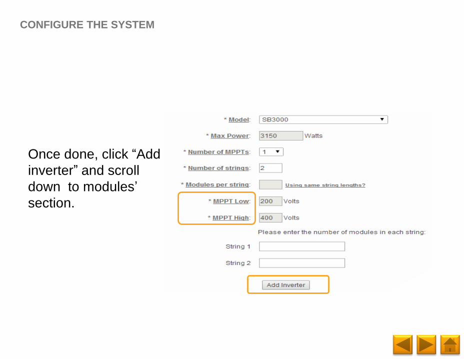
Once done, click “Add
inverter” and scroll
down to modules’
section.
CONFIGURE THE SYSTEM
Page 44
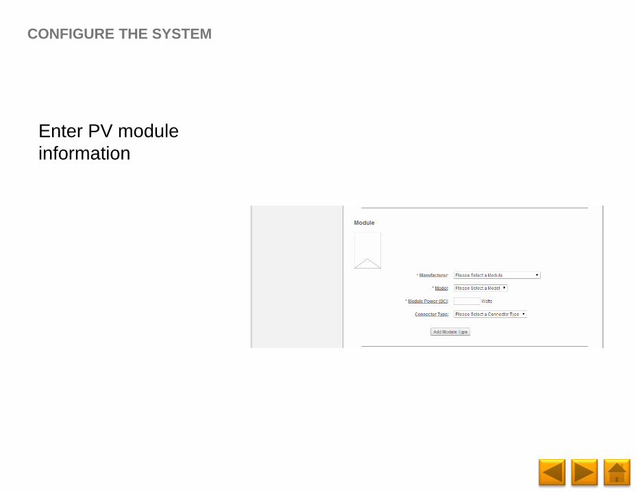
Enter PV module
information
CONFIGURE THE SYSTEM
Page 45
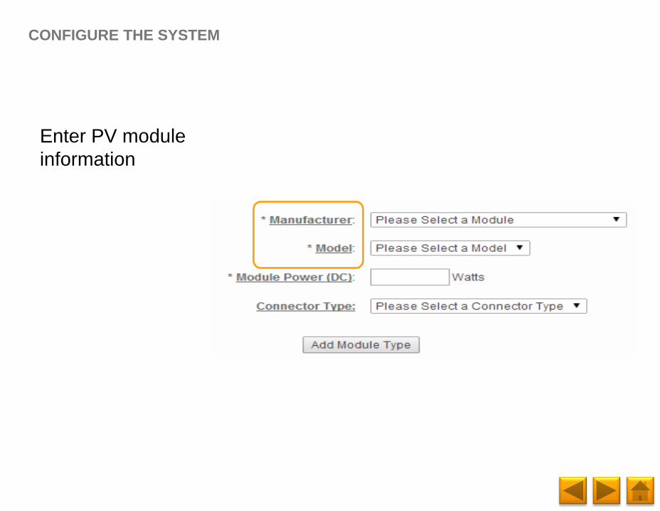
Enter PV module
information
CONFIGURE THE SYSTEM
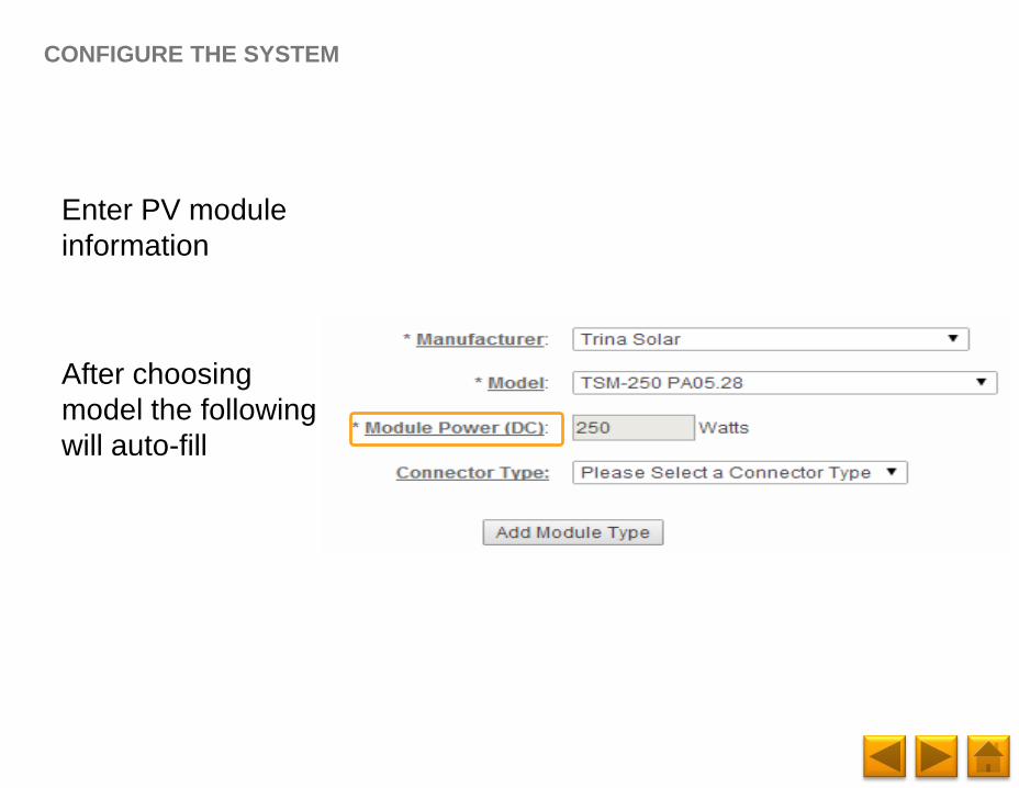
Page 46
Enter PV module
information
After choosing
model the following
will auto-fill
CONFIGURE THE SYSTEM
Page 47
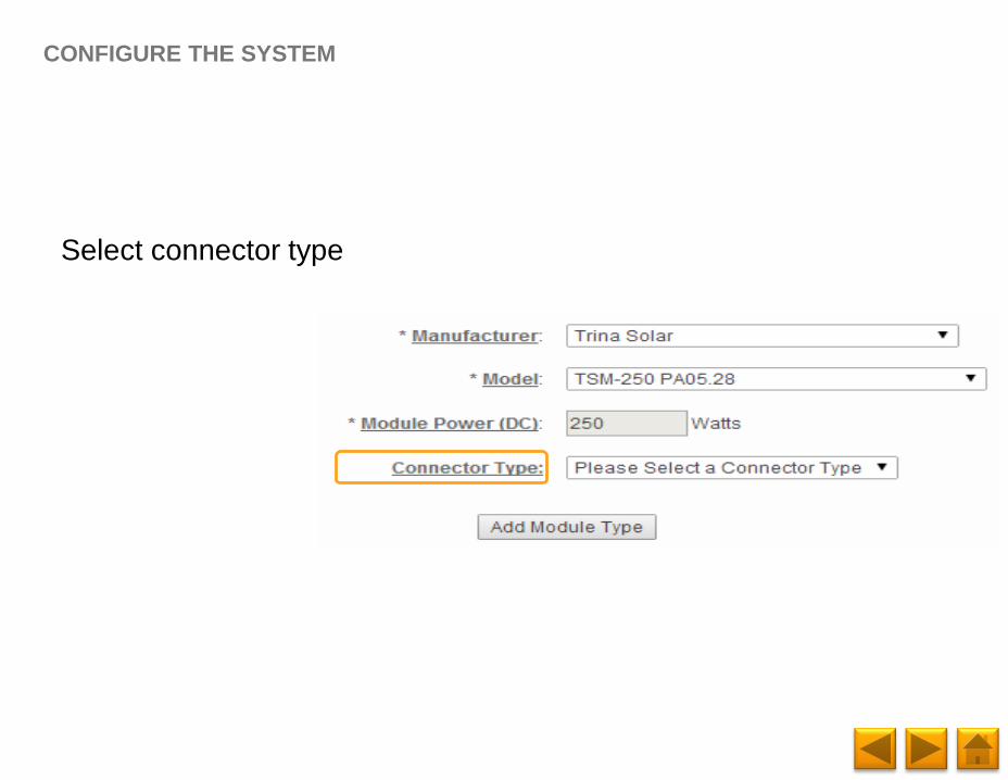
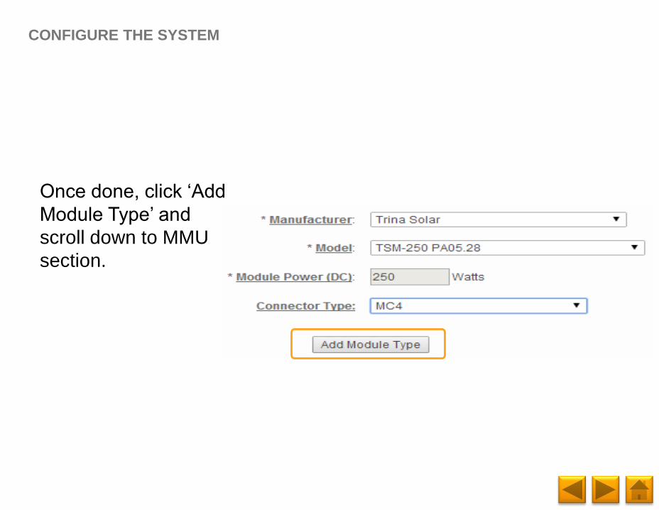
Select connector type
CONFIGURE THE SYSTEM
Page 48
Once done, click ‘Add
Module Type’ and
scroll down to MMU
section.
CONFIGURE THE SYSTEM
Page 49
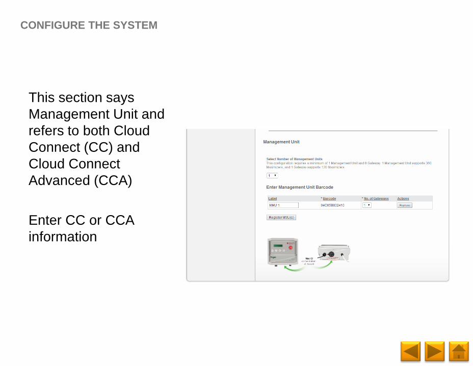
This section says
Management Unit and
refers to both Cloud
Connect (CC) and
Cloud Connect
Advanced (CCA)
Enter CC or CCA
information
CONFIGURE THE SYSTEM
Page 50
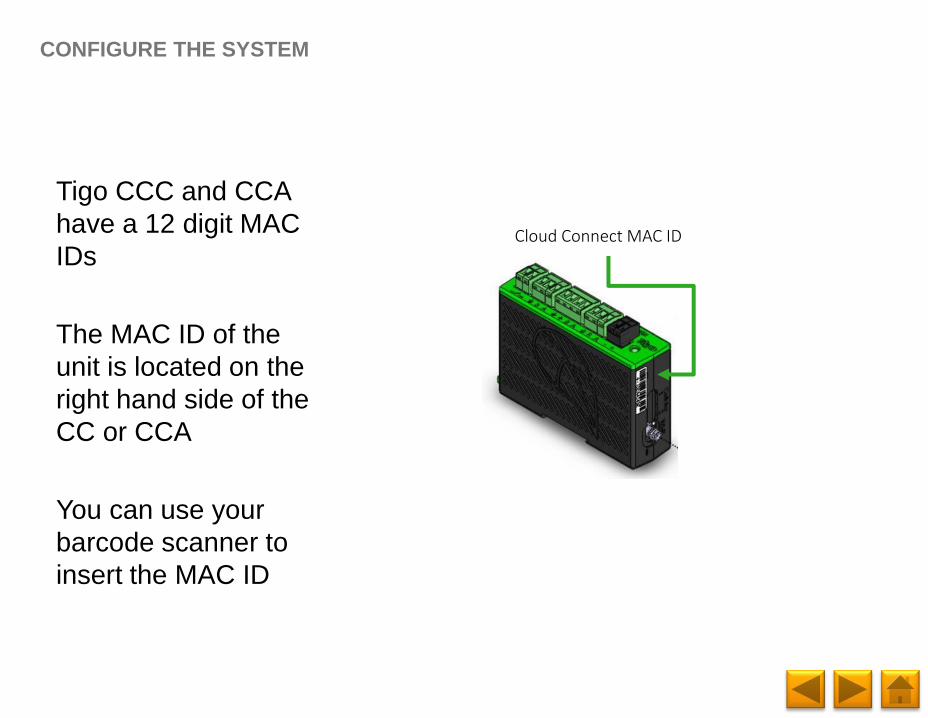
Tigo CCC and CCA
have a 12 digit MAC
IDs
The MAC ID of the
unit is located on the
right hand side of the
CC or CCA
You can use your
barcode scanner to
insert the MAC ID
CONFIGURE THE SYSTEM
Cloud Connect MAC ID
Page 51
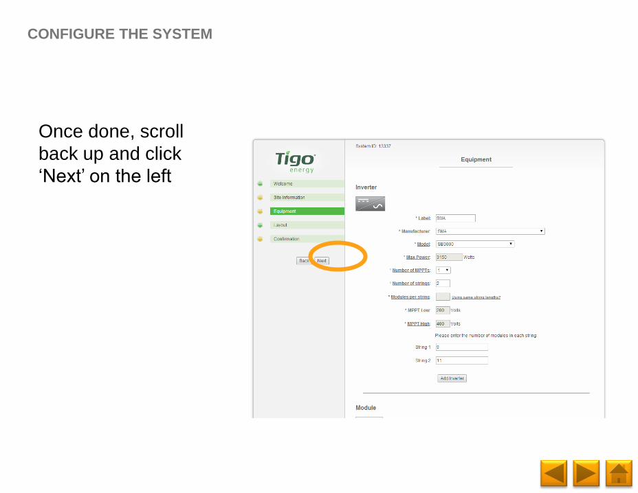
Once done, scroll
back up and click
‘Next’ on the left
CONFIGURE THE SYSTEM
Page 52
CONFIGURE THE SYSTEM
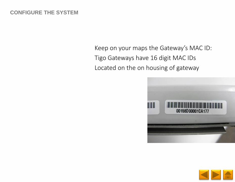
Keep on your maps the Gateway’s MAC ID:
Tigo Gateways have 16 digit MAC IDs
Located on the on housing of gateway
Page 53
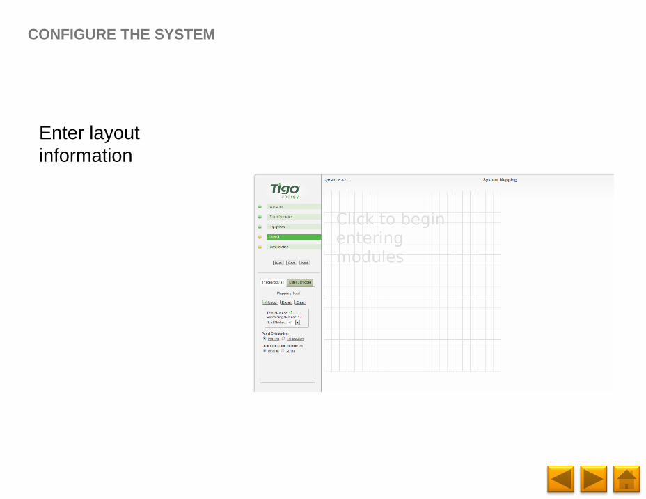
Enter layout
information
CONFIGURE THE SYSTEM
Page 54
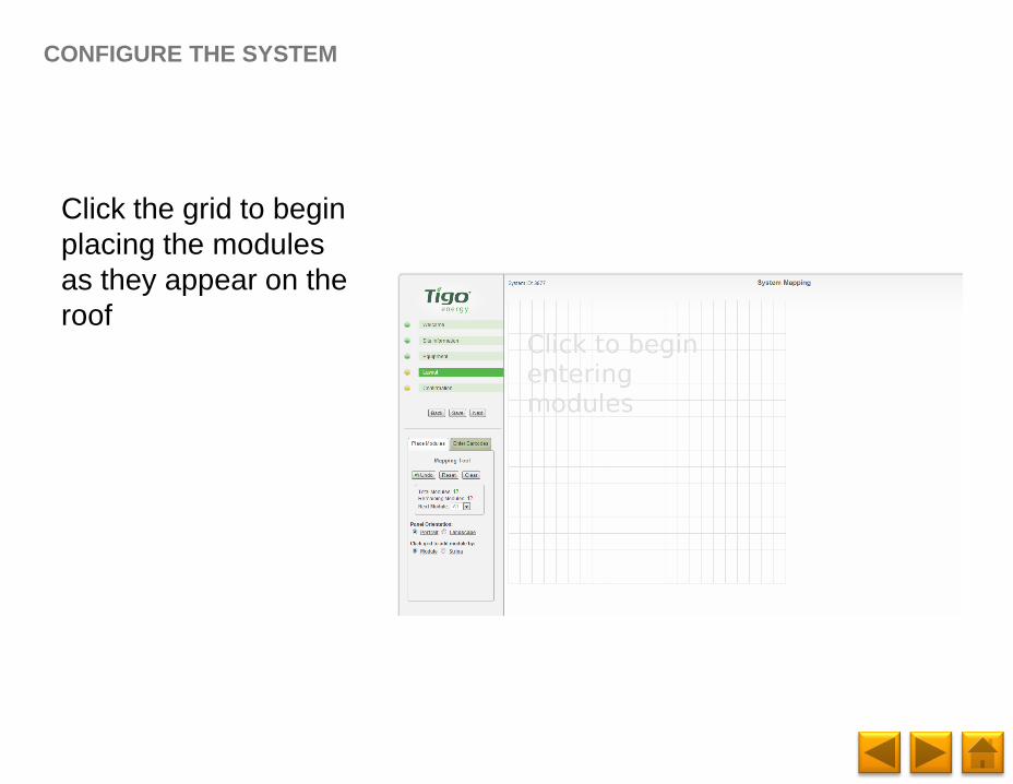
Click the grid to begin
placing the modules
as they appear on the
roof
CONFIGURE THE SYSTEM
Page 55
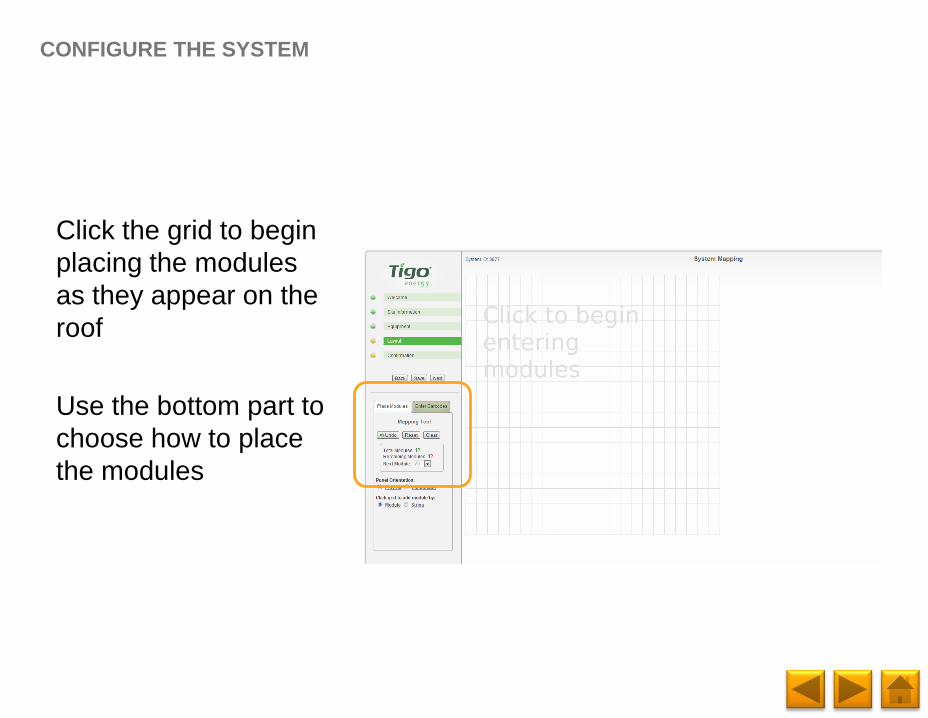
Click the grid to begin
placing the modules
as they appear on the
roof
Use the bottom part to
choose how to place
the modules
CONFIGURE THE SYSTEM
Page 56
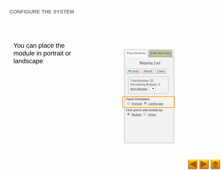
You can place the
module in portrait or
landscape
CONFIGURE THE SYSTEM
Page 57
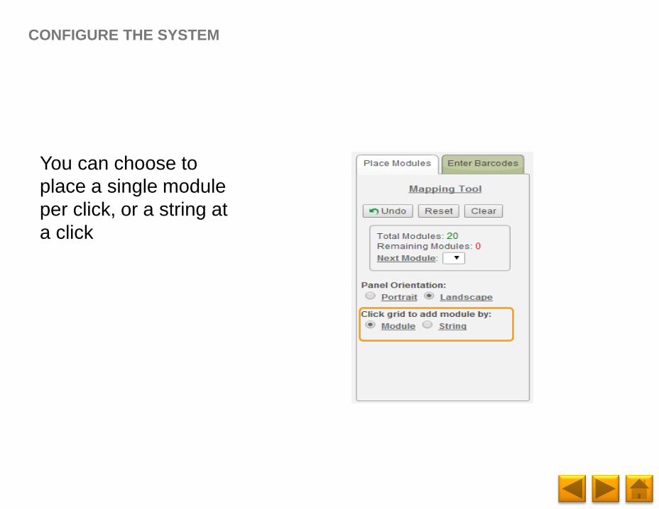
You can choose to
place a single module
per click, or a string at
a click
CONFIGURE THE SYSTEM
Page 58
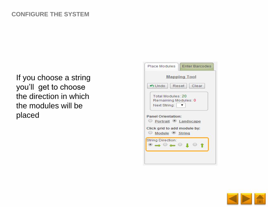
If you choose a string
you’ll get to choose
the direction in which
the modules will be
placed
CONFIGURE THE SYSTEM
Page 59
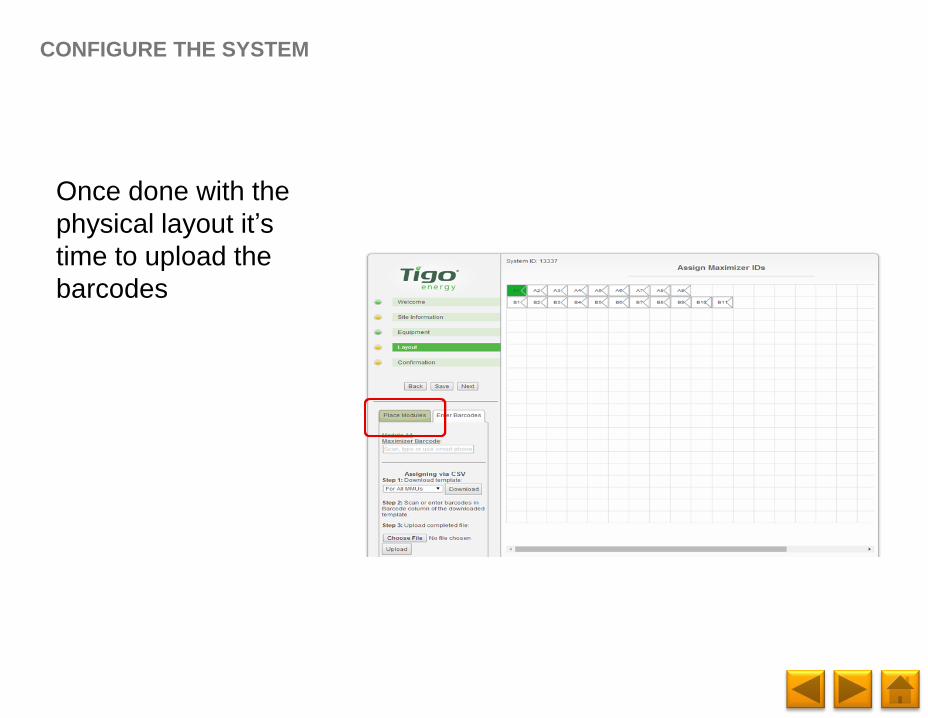
Once done with the
physical layout it’s
time to upload the
barcodes
CONFIGURE THE SYSTEM
Page 60
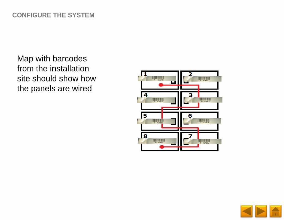
Map with barcodes
from the installation
site should show how
the panels are wired
CONFIGURE THE SYSTEM
Page 61
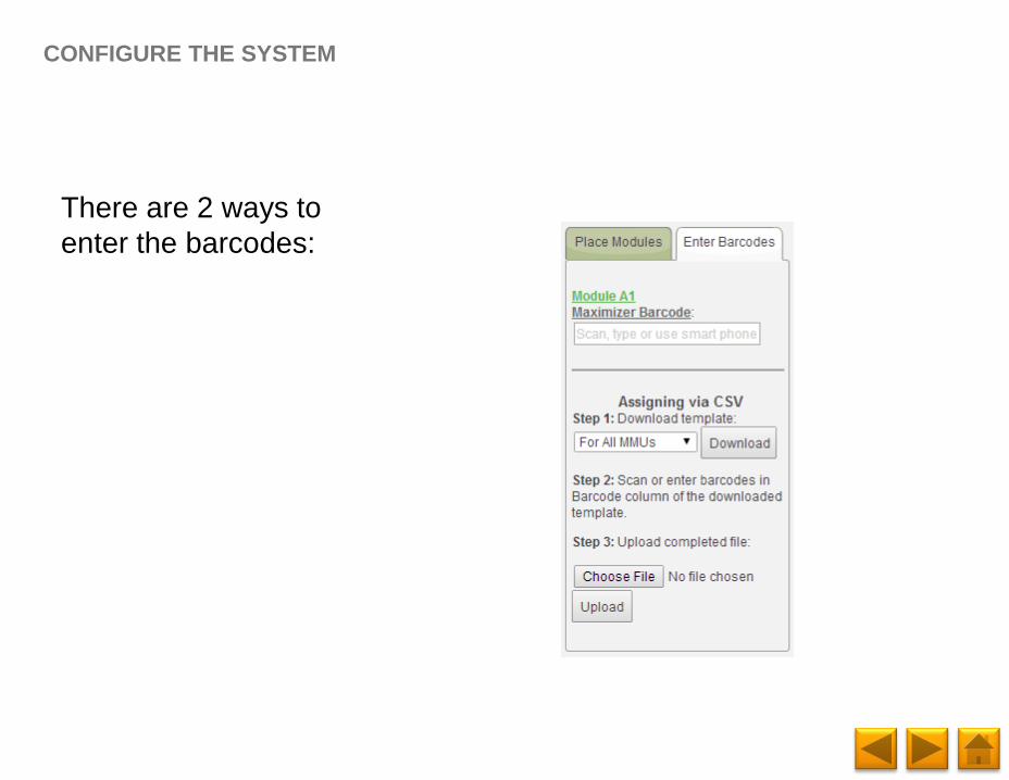
There are 2 ways to
enter the barcodes:
CONFIGURE THE SYSTEM
Page 62
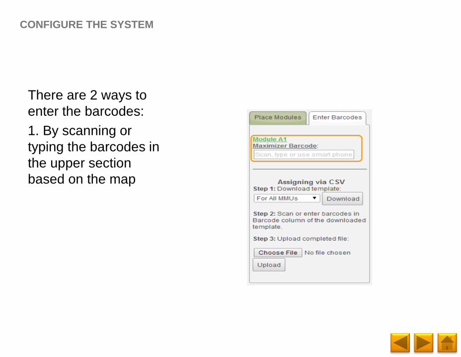
There are 2 ways to
enter the barcodes:
1. By scanning or
typing the barcodes in
the upper section
based on the map
CONFIGURE THE SYSTEM
Page 63
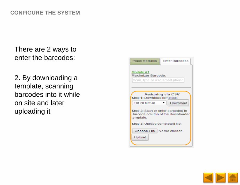
There are 2 ways to
enter the barcodes:
2. By downloading a
template, scanning
barcodes into it while
on site and later
uploading it
CONFIGURE THE SYSTEM
Page 64
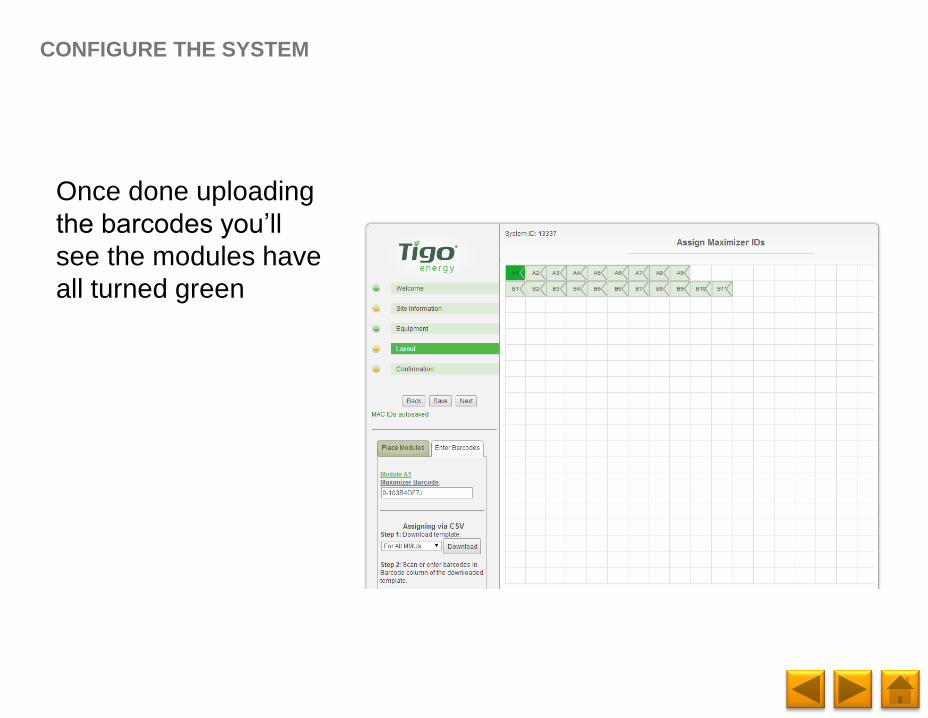
Once done uploading
the barcodes you’ll
see the modules have
all turned green
CONFIGURE THE SYSTEM
Page 65
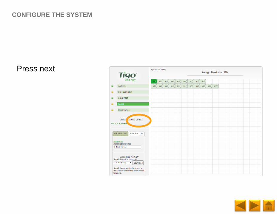
Press next
CONFIGURE THE SYSTEM
Page 66
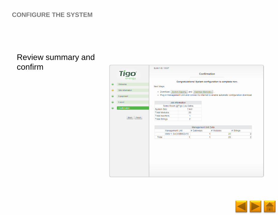
Review summary and
confirm
CONFIGURE THE SYSTEM
Page 67
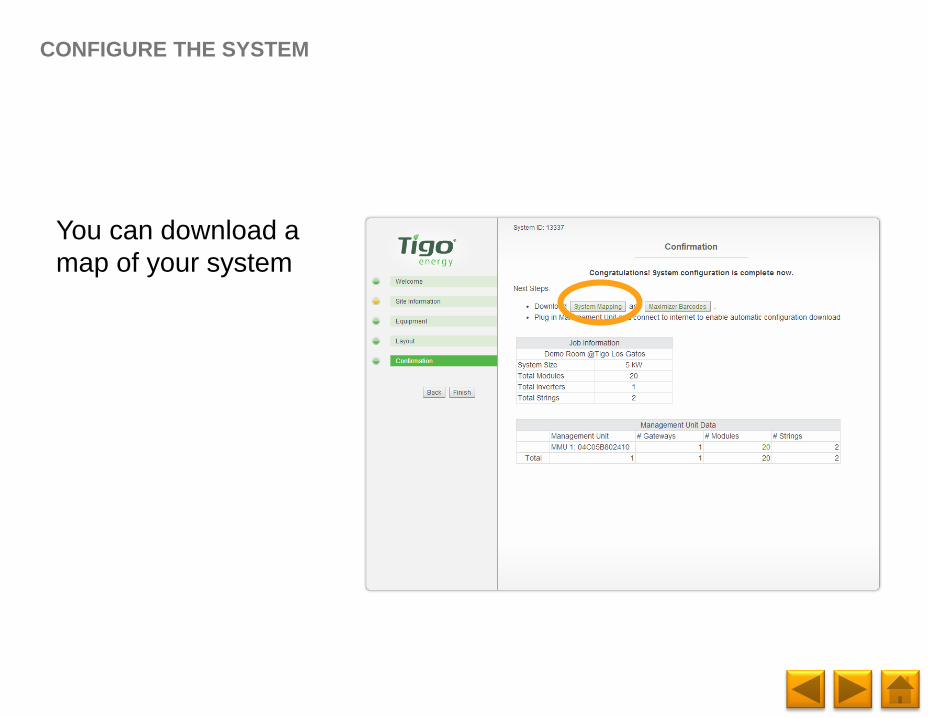
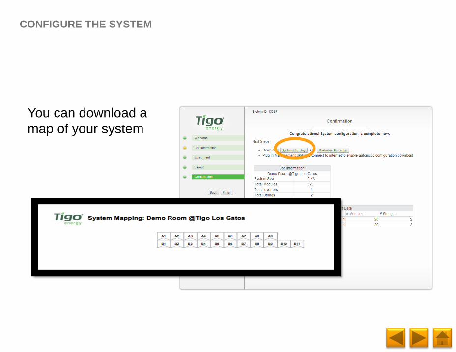
You can download a
map of your system
CONFIGURE THE SYSTEM
Page 68
You can download a
map of your system
CONFIGURE THE SYSTEM
Page 69
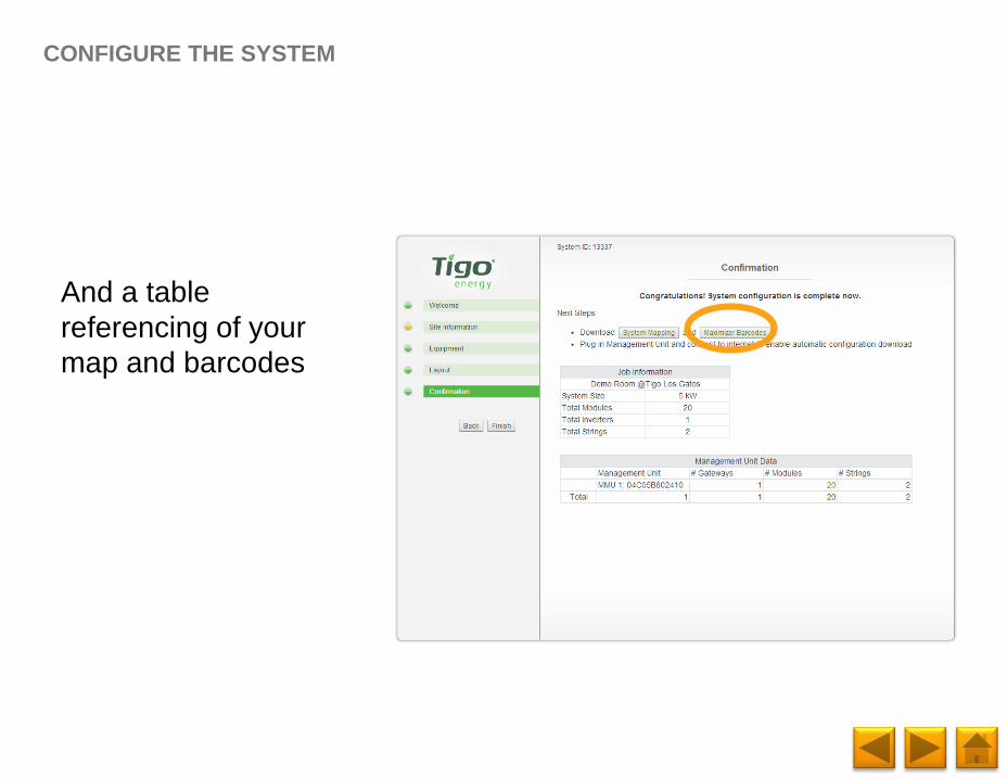
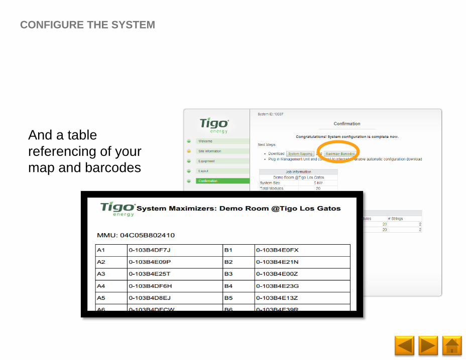
And a table
referencing of your
map and barcodes
CONFIGURE THE SYSTEM
Page 70
And a table
referencing of your
map and barcodes
CONFIGURE THE SYSTEM
Page 71
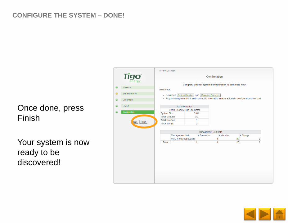
Once done, press
Finish
Your system is now
ready to be
discovered!
CONFIGURE THE SYSTEM – DONE!
Page 72
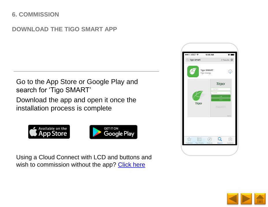
Go to the App Store or Google Play and
search for ‘Tigo SMART’
Download the app and open it once the
installation process is complete
Using a Cloud Connect with LCD and buttons and
wish to commission without the app? Click here
6. COMMISSION
DOWNLOAD THE TIGO SMART APP
Page 73
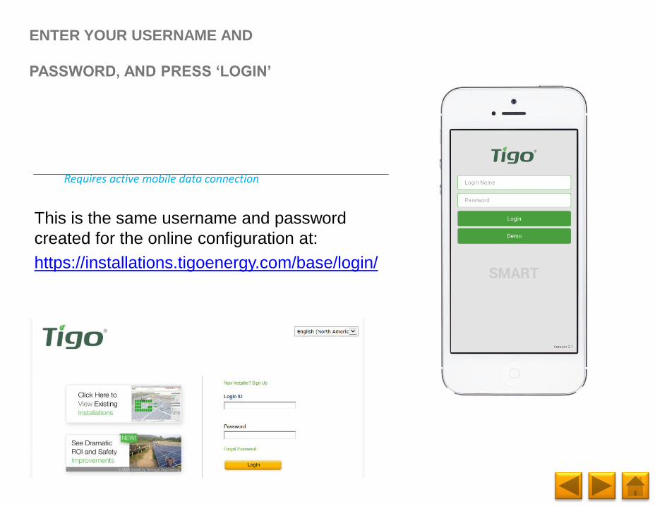
This is the same username and password
created for the online configuration at:
https://installations.tigoenergy.com/base/login/
ENTER YOUR USERNAME AND
PASSWORD, AND PRESS ‘LOGIN’
Requires active mobile data connection
Page 74
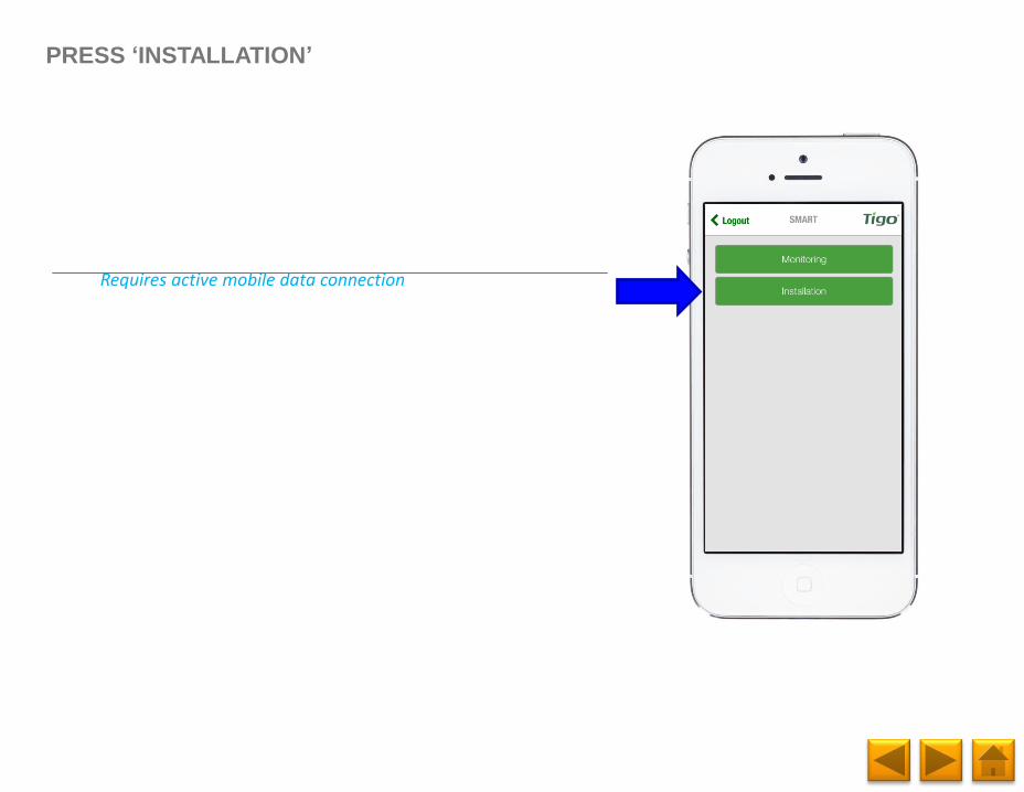
PRESS ‘INSTALLATION’
Requires active mobile data connection
Page 75
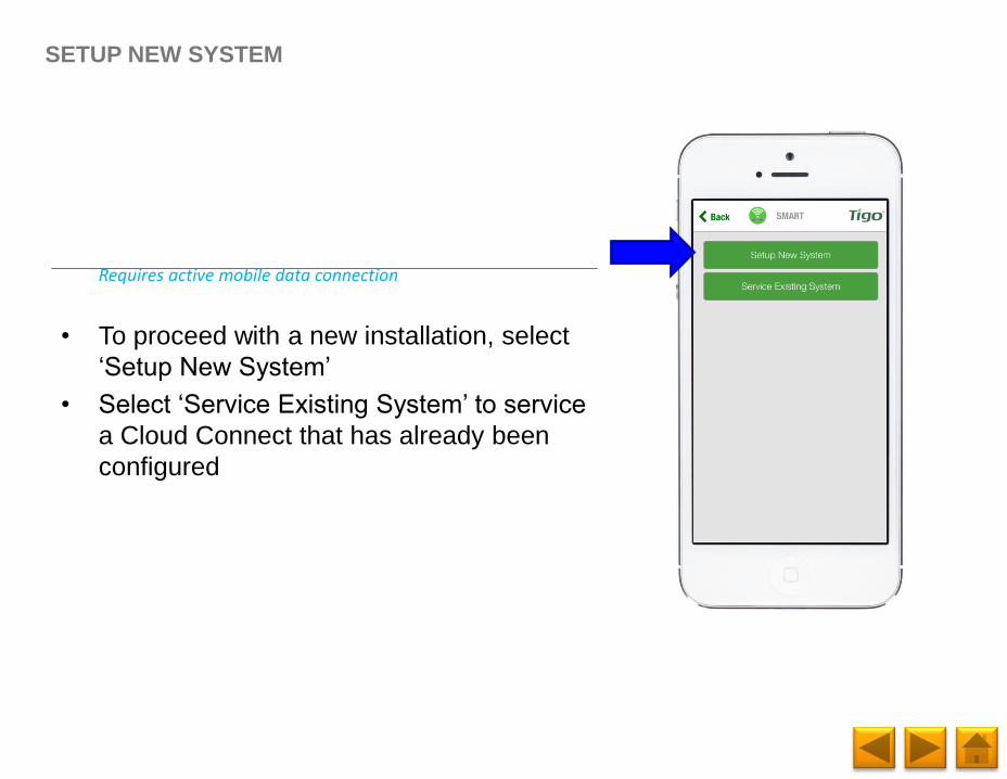
SETUP NEW SYSTEM
Requires active mobile data connection
• To proceed with a new installation, select
‘Setup New System’
• Select ‘Service Existing System’ to service
a Cloud Connect that has already been
configured
Page 76
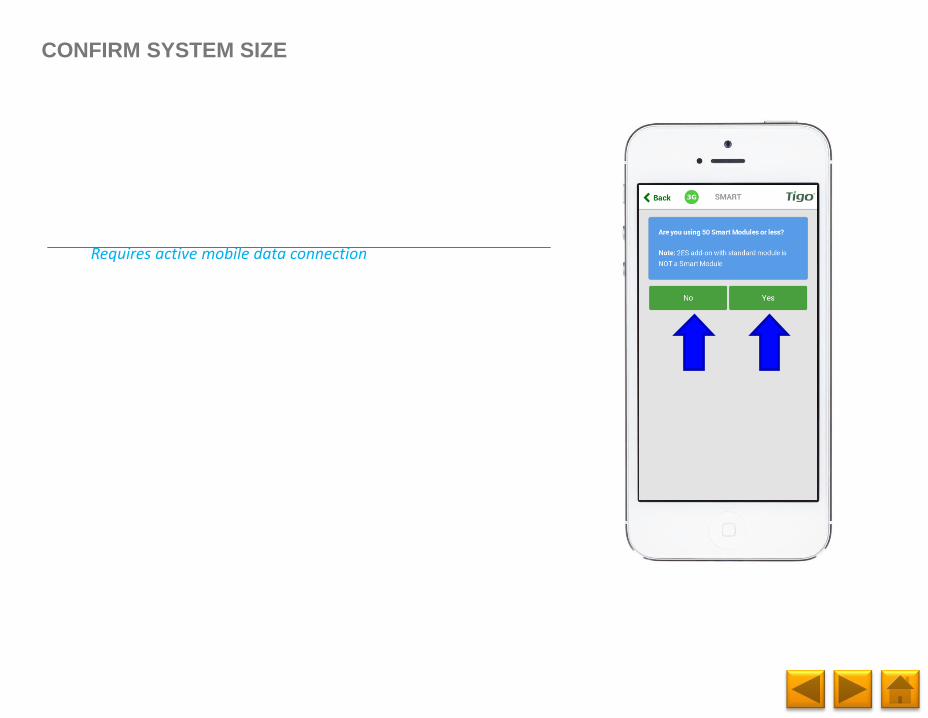
CONFIRM SYSTEM SIZE
Requires active mobile data connection
Page 77
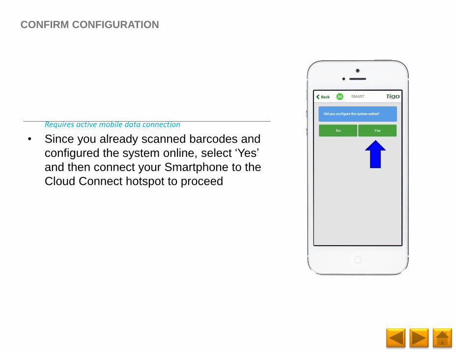
• Since you already scanned barcodes and
configured the system online, select ‘Yes’
and then connect your Smartphone to the
Cloud Connect hotspot to proceed
CONFIRM CONFIGURATION
Requires active mobile data connection
Page 78
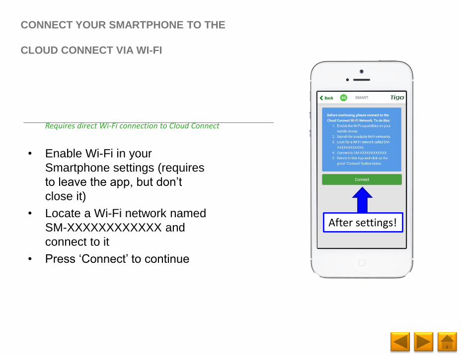
• Enable Wi-Fi in your
Smartphone settings (requires
to leave the app, but don’t
close it)
• Locate a Wi-Fi network named
SM-XXXXXXXXXXXX and
connect to it
• Press ‘Connect’ to continue
CONNECT YOUR SMARTPHONE TO THE
CLOUD CONNECT VIA WI-FI
Requires direct Wi-Fi connection to Cloud Connect
After settings!
Page 79
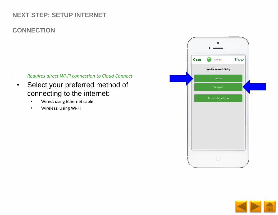
• Select your preferred method of
connecting to the internet:• Wired: using Ethernet cable
• Wireless: Using Wi-Fi
NEXT STEP: SETUP INTERNET
CONNECTION
Requires direct Wi-Fi connection to Cloud Connect
Page 80
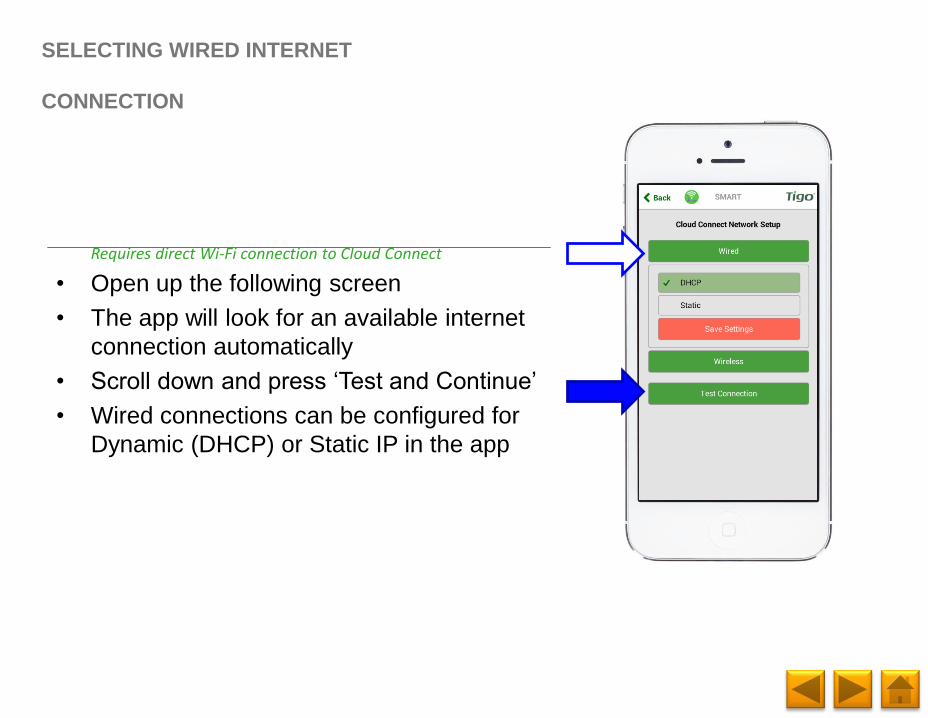
• Open up the following screen
• The app will look for an available internet
connection automatically
• Scroll down and press ‘Test and Continue’
• Wired connections can be configured for
Dynamic (DHCP) or Static IP in the app
SELECTING WIRED INTERNET
CONNECTION
Requires direct Wi-Fi connection to Cloud Connect
Page 81
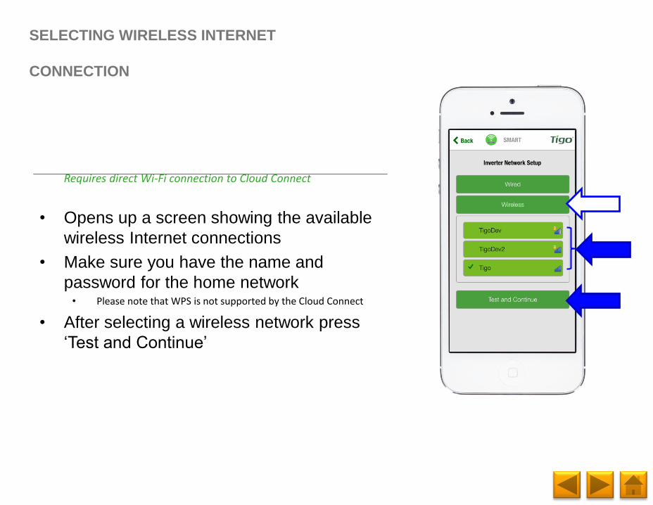
• Opens up a screen showing the available
wireless Internet connections
• Make sure you have the name and
password for the home network• Please note that WPS is not supported by the Cloud Connect
• After selecting a wireless network press
‘Test and Continue’
SELECTING WIRELESS INTERNET
CONNECTION
Requires direct Wi-Fi connection to Cloud Connect
Page 82
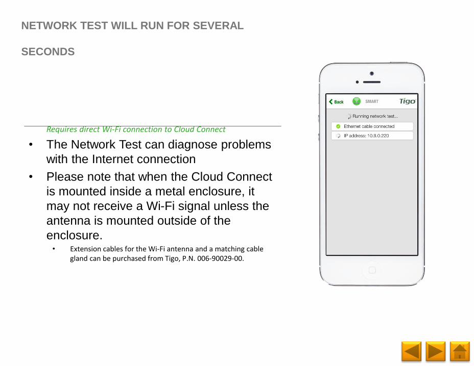
• The Network Test can diagnose problems
with the Internet connection
• Please note that when the Cloud Connect
is mounted inside a metal enclosure, it
may not receive a Wi-Fi signal unless the
antenna is mounted outside of the
enclosure. • Extension cables for the Wi-Fi antenna and a matching cable
gland can be purchased from Tigo, P.N. 006-90029-00.
NETWORK TEST WILL RUN FOR SEVERAL
SECONDS
Requires direct Wi-Fi connection to Cloud Connect
Page 83
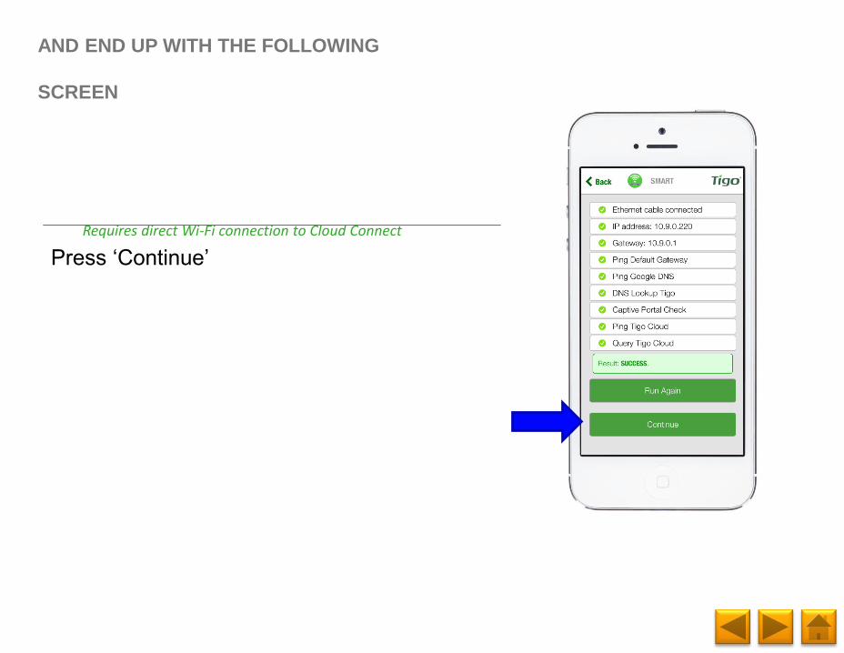
Press ‘Continue’
AND END UP WITH THE FOLLOWING
SCREEN
Requires direct Wi-Fi connection to Cloud Connect
Page 84
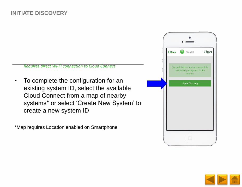
• To complete the configuration for an
existing system ID, select the available
Cloud Connect from a map of nearby
systems* or select ‘Create New System’ to
create a new system ID
*Map requires Location enabled on Smartphone
INITIATE DISCOVERY
Requires direct Wi-Fi connection to Cloud Connect
Page 85
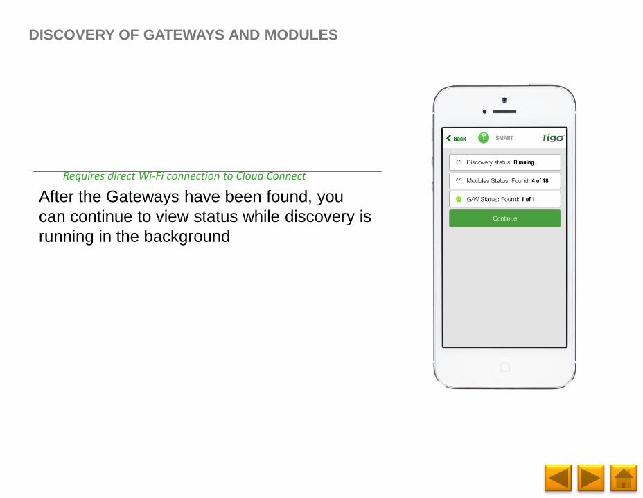
After the Gateways have been found, you
can continue to view status while discovery is
running in the background
DISCOVERY OF GATEWAYS AND MODULES
Requires direct Wi-Fi connection to Cloud Connect
Page 86
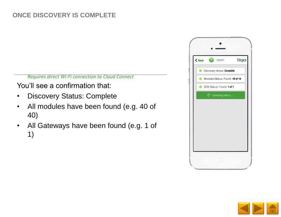
You’ll see a confirmation that:
• Discovery Status: Complete
• All modules have been found (e.g. 40 of
40)
• All Gateways have been found (e.g. 1 of
1)
ONCE DISCOVERY IS COMPLETE
Requires direct Wi-Fi connection to Cloud Connect
Page 87
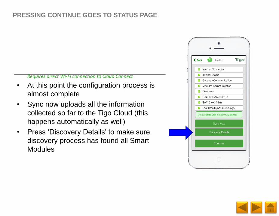
• At this point the configuration process is
almost complete
• Sync now uploads all the information
collected so far to the Tigo Cloud (this
happens automatically as well)
• Press ‘Discovery Details’ to make sure
discovery process has found all Smart
Modules
PRESSING CONTINUE GOES TO STATUS PAGE
Requires direct Wi-Fi connection to Cloud Connect
Page 88
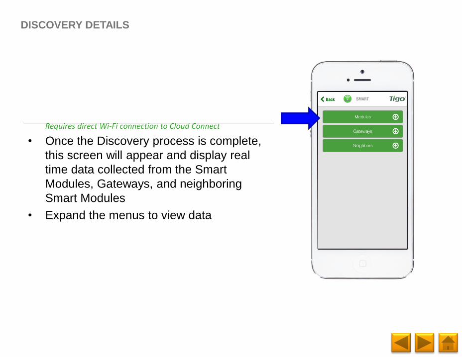
• Once the Discovery process is complete,
this screen will appear and display real
time data collected from the Smart
Modules, Gateways, and neighboring
Smart Modules
• Expand the menus to view data
DISCOVERY DETAILS
Requires direct Wi-Fi connection to Cloud Connect
Page 89
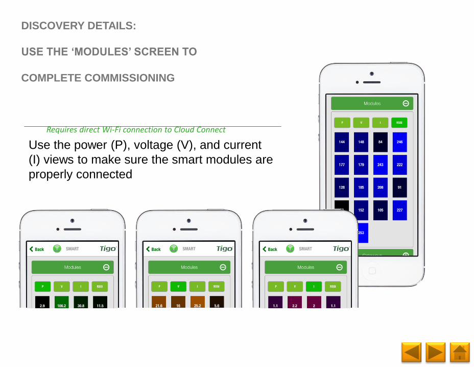
Use the power (P), voltage (V), and current
(I) views to make sure the smart modules are
properly connected
DISCOVERY DETAILS:
USE THE ‘MODULES’ SCREEN TO
COMPLETE COMMISSIONING
Requires direct Wi-Fi connection to Cloud Connect
Page 90
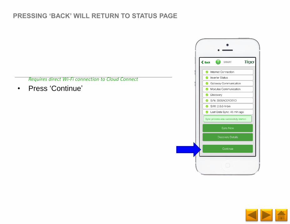
• Press ‘Continue’
PRESSING ‘BACK’ WILL RETURN TO STATUS PAGE
Requires direct Wi-Fi connection to Cloud Connect
Page 91
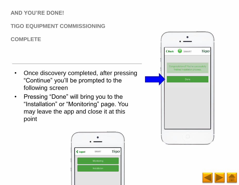
AND YOU’RE DONE!
TIGO EQUIPMENT COMMISSIONING
COMPLETE
• Once discovery completed, after pressing
“Continue” you’ll be prompted to the
following screen
• Pressing “Done” will bring you to the
“Installation” or “Monitoring” page. You
may leave the app and close it at this
point
Page 92
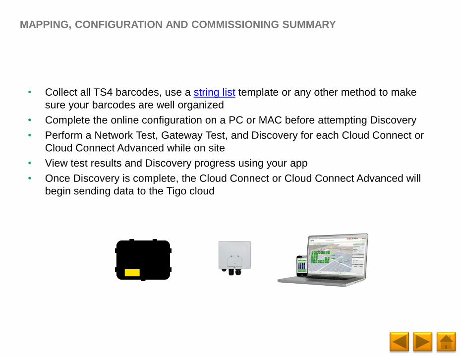
MAPPING, CONFIGURATION AND COMMISSIONING SUMMARY
• Collect all TS4 barcodes, use a string list template or any other method to make
sure your barcodes are well organized
• Complete the online configuration on a PC or MAC before attempting Discovery
• Perform a Network Test, Gateway Test, and Discovery for each Cloud Connect or
Cloud Connect Advanced while on site
• View test results and Discovery progress using your app
• Once Discovery is complete, the Cloud Connect or Cloud Connect Advanced will
begin sending data to the Tigo cloud
Page 93
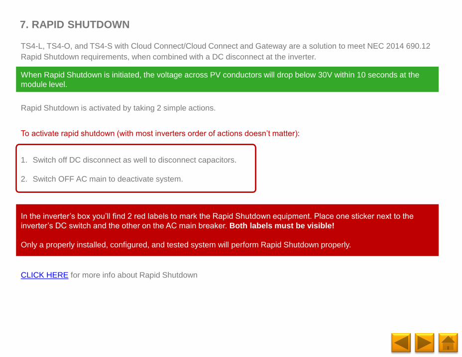
7. RAPID SHUTDOWN
When Rapid Shutdown is initiated, the voltage across PV conductors will drop below 30V within 10 seconds at the
module level.
In the inverter’s box you’ll find 2 red labels to mark the Rapid Shutdown equipment. Place one sticker next to the
inverter’s DC switch and the other on the AC main breaker. Both labels must be visible!
Only a properly installed, configured, and tested system will perform Rapid Shutdown properly.
CLICK HERE for more info about Rapid Shutdown
TS4-L, TS4-O, and TS4-S with Cloud Connect/Cloud Connect and Gateway are a solution to meet NEC 2014 690.12
Rapid Shutdown requirements, when combined with a DC disconnect at the inverter.
Rapid Shutdown is activated by taking 2 simple actions.
To activate rapid shutdown (with most inverters order of actions doesn’t matter):
1. Switch off DC disconnect as well to disconnect capacitors.
2. Switch OFF AC main to deactivate system.
Page 94
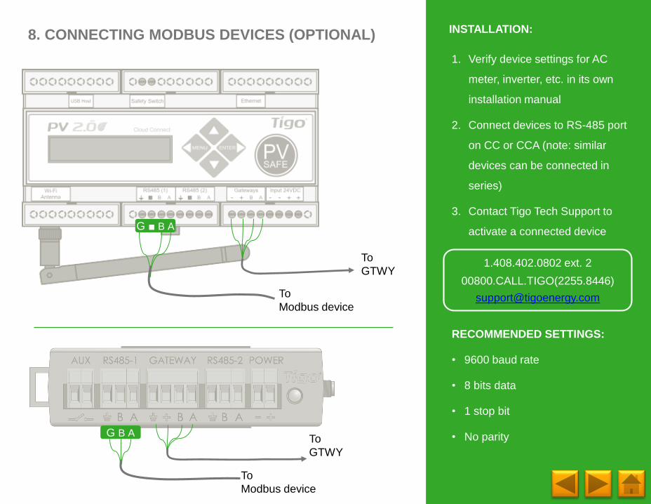
8. CONNECTING MODBUS DEVICES (OPTIONAL)
G ■ B A
To
GTWY1.408.402.0802 ext. 2
00800.CALL.TIGO(2255.8446)
[email protected]
G B ATo
GTWY
To
Modbus device
To
Modbus device
1. Verify device settings for AC
meter, inverter, etc. in its own
installation manual
2. Connect devices to RS-485 port
on CC or CCA (note: similar
devices can be connected in
series)
3. Contact Tigo Tech Support to
activate a connected device
RECOMMENDED SETTINGS:
• 9600 baud rate
• 8 bits data
• 1 stop bit
• No parity
INSTALLATION:
Page 95
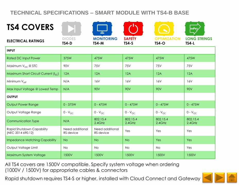
TS4 COVERS
ELECTRICAL RATINGSDIODESTS4-D
MONITORINGTS4-M
SAFETYTS4-S
OPTIMIZATIONTS4-O
LONG STRINGSTS4-L
INPUT
Rated DC Input Power 375W 475W 475W 475W 475W
Maximum VOC @ STC 90V 75V 75V 75V 75V
Maximum Short Circuit Current (ISC) 12A 12A 12A 12A 12A
Minimum VMP N/A 16V 16V 16V 16V
Max Input Voltage @ Lowest Temp N/A 90V 90V 90V 90V
OUTPUT
Output Power Range 0 - 375W 0 - 475W 0 - 475W 0 - 475W 0 - 475W
Output Voltage Range 0 - VOC 0 - VOC 0 - VOC 0 - VOC 0 - VOC
Communication Type N/A802.15.4
2.4GHz
802.15.4
2.4GHz
802.15.4
2.4GHz
802.15.4
2.4GHz
Rapid Shutdown Capability
(NEC 2014 690.12)
Need additional
RS device
Need additional
RS deviceYes Yes Yes
Impedance Matching Capability No No No Yes Yes
Output Voltage Limit No No No No Yes
Maximum System Voltage 1500V 1500V 1500V 1500V 1500V
TECHNICAL SPECIFICATIONS – SMART MODULE WITH TS4-B BASE
All TS4 covers are 1500V compatible. Specify system voltage when ordering (1000V / 1500V) for appropriate cables & connectors
Rapid shutdown requires TS4-S or higher, installed with Cloud Connect and Gateway
Page 96
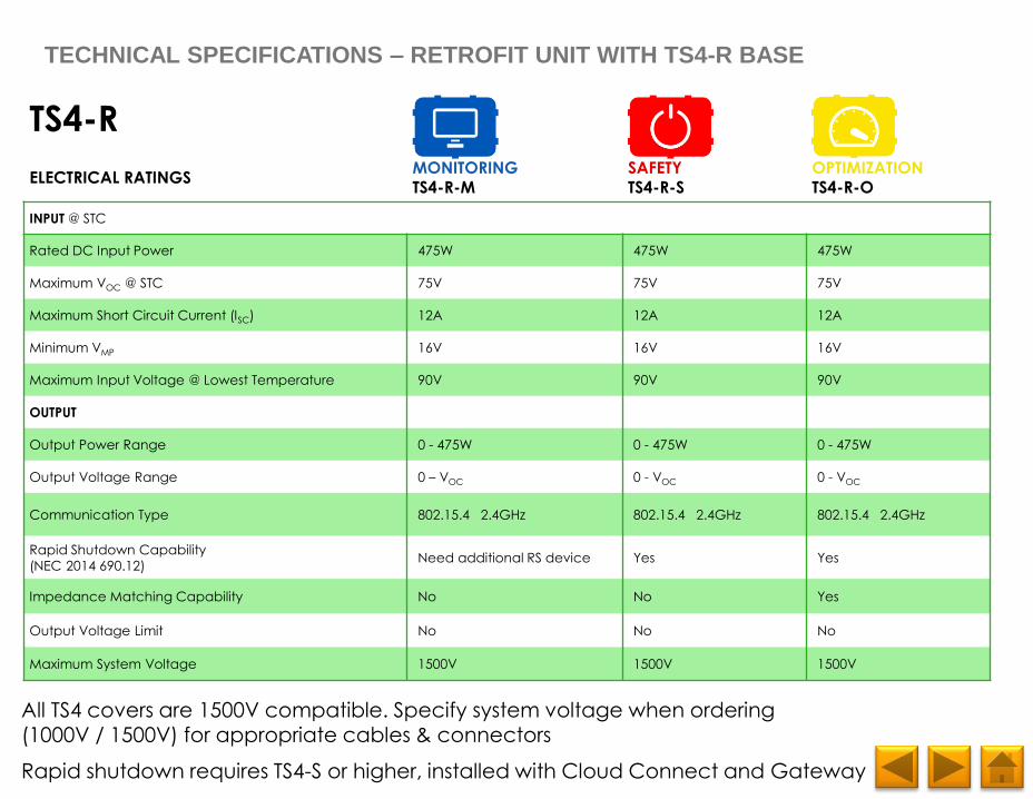
TS4-R
ELECTRICAL RATINGSMONITORINGTS4-R-M
SAFETYTS4-R-S
OPTIMIZATIONTS4-R-O
INPUT @ STC
Rated DC Input Power 475W 475W 475W
Maximum VOC @ STC 75V 75V 75V
Maximum Short Circuit Current (ISC) 12A 12A 12A
Minimum VMP 16V 16V 16V
Maximum Input Voltage @ Lowest Temperature 90V 90V 90V
OUTPUT
Output Power Range 0 - 475W 0 - 475W 0 - 475W
Output Voltage Range 0 – VOC 0 - VOC 0 - VOC
Communication Type 802.15.4 2.4GHz 802.15.4 2.4GHz 802.15.4 2.4GHz
Rapid Shutdown Capability
(NEC 2014 690.12)Need additional RS device Yes Yes
Impedance Matching Capability No No Yes
Output Voltage Limit No No No
Maximum System Voltage 1500V 1500V 1500V
TECHNICAL SPECIFICATIONS – RETROFIT UNIT WITH TS4-R BASE
All TS4 covers are 1500V compatible. Specify system voltage when ordering (1000V / 1500V) for appropriate cables & connectors
Rapid shutdown requires TS4-S or higher, installed with Cloud Connect and Gateway
Page 97
TECHNICAL SPECIFICATIONS
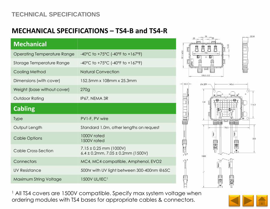
MECHANICAL SPECIFICATIONS – TS4-B and TS4-R
Mechanical
Operating Temperature Range -40°C to +75°C (-40°F to +167°F)
Storage Temperature Range -40°C to +75°C (-40°F to +167°F)
Cooling Method Natural Convection
Dimensions (with cover) 152.5mm x 108mm x 25.3mm
Weight (base without cover) 270g
Outdoor Rating IP67, NEMA 3R
Cabling
Type PV1-F, PV wire
Output Length Standard 1.0m, other lengths on request
Cable Options1000V rated1500V rated
Cable Cross-Section7.15 ± 0.25 mm (1000V)6.4 ± 0.2mm, 7.05 ± 0.2mm (1500V)
Connectors MC4, MC4 compatible, Amphenol, EVO2
UV Resistance 500hr with UV light between 300-400nm @65C
Maximum String Voltage 1500V UL/IEC1
1 All TS4 covers are 1500V compatible. Specify max system voltage when ordering modules with TS4 bases for appropriate cables & connectors.
Page 98
YOU’RE GOOD TO GO!
For more details on designing and installing solutions
powered by Tigo, please visit:
• Tigo Academy
• Resource Center
Or contact us at:
• [email protected]
GOOD LUCK!
Tigo Team