A DIVISION OF DOUGLAS DYNAMICS, LLC September 15, 2020 Lit. No. 74328, Rev. 00 CAUTION Read this document before installing the harness kit. CAUTION See your sales outlet/website for specific vehicle application recommendations before installation. The online selection system has specific vehicle and snowplow requirements. 74973-1 HARNESS KIT 3-PORT ISOLATION MODULE LIGHT SYSTEM w/QUAD HALOGEN-STYLE VEHICLE LIGHTING Parts List and Installation Instructions
Transcript
A DIVISION OF DOUGLAS DYNAMICS, LLC
September 15, 2020Lit. No. 74328, Rev. 00
CAUTIONRead this document before installing the harness kit.
CAUTIONSee your sales outlet/website for specifi c vehicle application recommendations before installation. The online selection system has specifi c vehicle and snowplow requirements.
NOTE: Indicates a situation or action that can lead to damage to your snowplow and vehicle or other property. Other useful information can also be described.
FUSES
The snowplow electrical and hydraulic systems contain several automotive-style fuses. If a problem should occur and fuse replacement is necessary, the replacement fuse must be of the same type and amperage rating as the original. Installing a fuse with a higher rating can damage the system and could start a fi re. Fuse Replacement, including fuse ratings and locations, is located in the Maintenance section of the Owner's Manual.
BATTERY SAFETY
CAUTIONIndicates a potentially hazardous situation that, if not avoided, may result in minor or moderate injury. It may also be used to alert against unsafe practices.
These torque values apply to fastenersexcept those noted in the instructions.
Torque (ft-lb)Grade
5Grade
8
Size SizeTorque (ft-lb)
Class8.8
Class10.9
Torque (ft-lb)Class
8.8Class10.9
Inch Fasteners Grade 5 and Grade 8
CAUTIONRead instructions before assembling. Fasteners should be fi nger tight until instructed to tighten according to the torque chart. Use standard methods and practices when attaching snowplow, including proper personal protective safety equipment.
WARNINGIndicates a potentially hazardous situation that, if not avoided, could result in death or serious personal injury.
CAUTIONBatteries normally produce explosive gases, which can cause personal injury. Therefore, do not allow fl ames, sparks, or lit tobacco to come near the battery. When charging or working near a battery, always cover your face and protect your eyes, and also provide ventilation.• Batteries contain sulfuric acid, which burns
skin, eyes, and clothing.• Disconnect the battery before removing or
replacing any electrical components.
Lit. No. 74328, Rev. 00 4 September 15, 2020
74973-1
* In
clud
ed in
200
A F
use
Kit
(PN
907
30).
200A
Fus
ean
d H
olde
r*
8" C
able
*
Bat
tery
Plug
-In H
arne
ss
Vehi
cle
Con
trol
Har
ness
Vehi
cle
Bat
tery
Cab
le
To S
now
plow
Con
trol
BAT
Rel
ays
Vehi
cle
Ligh
ting
Har
ness
(11-
pin)
10A
Fus
es(s
now
plow
par
k/tu
rn &
sn
owpl
ow c
ontro
l)
RE
D
BLK
To S
witc
hed
Acc
esso
ry(T
his
conn
ectio
nis
not
requ
ired.
)
Fire Wall
3-Po
rt M
odul
e
RED
Factory Vehicle Harness
Fact
ory
Vehi
cle
Har
ness
Rel
ays
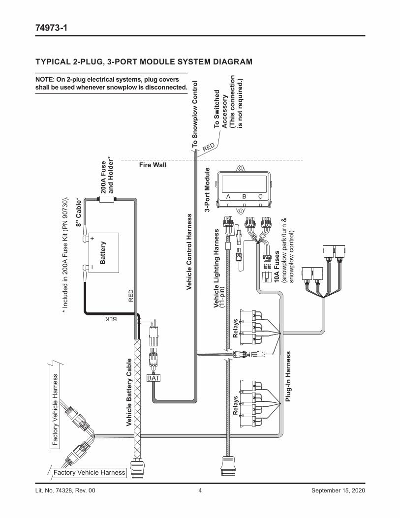
TYPICAL 2-PLUG, 3-PORT MODULE SYSTEM DIAGRAM
NOTE: On 2-plug electrical systems, plug covers shall be used whenever snowplow is disconnected.
Lit. No. 74328, Rev. 00 5 September 15, 2020
74973-1
Vehicle Battery Cable Installation
NOTE: Fuse holder and fuse are to be installed between the POSITIVE (+) vehicle battery terminal and the end of the supplied snowplow vehicle battery cable assembly.
NOTE: When instructed, make all snowplow battery cable connections to the auxiliary battery, if vehicle is so equipped.
NOTE: Use dielectric grease on all electrical connections to prevent corrosion. Fill receptacles and lightly coat ring terminals before assembly.
1. Turn OFF the vehicle ignition.
2. Disconnect both the NEGATIVE (–) and the POSITIVE (+) battery cables from the vehicle battery.
3. Route the supplied vehicle battery cable from the grille or bumper to the battery, avoiding any sharp edges and hot or moving parts. Cable tie only the end section closest to the grille.
CAUTIONBatteries normally produce explosive gases, which can cause personal injury. Therefore, do not allow fl ames, sparks, or lit tobacco to come near the battery. When charging or working near a battery, always cover your face and protect your eyes, and also provide ventilation.• Batteries contain sulfuric acid, which burns
skin, eyes, and clothing.• Disconnect the battery before removing or
replacing any electrical components.
PLUG-IN HARNESS INSTALLATION
1. Remove the passenger-side inner fender liner. Locate the black OEM-supplied 16-position snowplow interface connector attached to the factory wiring harness. Connect the plug-in harness to the mating connections on the factory harness. Refer to the system diagram.
2. Route the plug-in harness to the rear of the fender well so that the two 10-position connectors pass behind the factory fuse box and extend above the factory fuse box to connect to the isolation module.
3. Connect the plug-in harness to the isolation module by matching harness connector B with module port B and harness connector C with module port C. Do not mount the isolation module at this time.
Plug-in harness connection is shown.
Lit. No. 74328, Rev. 00 6 September 15, 2020
74973-1
4. Remove the fuse holder cover, loosen and remove the fuse holder nuts and lock washers. Install a 200A fuse into the fuse holder.
5. Attach one end of the supplied 8" cable to the fuse holder so that the ring terminal is on top of the fuse. Replace the lock washer and nut on this terminal and hand tighten the nut.
6. Attach the red lead from the vehicle battery cable to the second fuse holder terminal, placing the cable ring terminal on top of the fuse lead. Replace the lock washer and nut on this terminal and hand tighten the nut.
7. Torque the fuse holder nuts to 106–159 in-lb and snap the fuse holder cover into place.
8. Route the 8" cable from the fuse holder to the POSITIVE (+) battery terminal. Do not connect at this time.
9. Route the black wire from the vehicle battery cable to the NEGATIVE (–) battery connection point. Do not connect at this time. The 4-position connector from the vehicle battery cable will connect to the mating connector (labeled "BAT") on the end of the vehicle control harness.
Vehicle Lighting and Vehicle Control Harness Installation
For Halogen plow light installation, proceed with the following instructions.
For LED plow light installation, install the vehicle control harness as instructed, but DO NOT install the supplied vehicle lighting harness. Instead, refer to the LED Installation Instructions on page 9.
1. Route the 10-position connector side of the vehicle lighting harness from the radiator bulkhead to where the isolation module will be mounted on top of the vehicle fuse box.
2. Connect the single-wire connector from the vehicle lighting harness to the single-wire connector from the plug-in harness.
3. Connect the 4-position connector on the vehicle control harness to the matching 4-position connector on the plug-in harness.
4. Connect the vehicle lighting harness toposition "A" on the isolation module.
Lit. No. 74328, Rev. 00 7 September 15, 2020
74973-1
CAUTIONBefore installing self-drilling screws or drilling mounting holes, check the selected mounting area for any wires, hoses, or other obstructions.
5. Route the end of the vehicle control harness with the white 4-position connector to the fi re wall.
Connect the black 4-position connector (labeled "BAT") from the end of the vehicle control harness to the 4-position connector from the vehicle battery cable. Do not cable tie the harness at this time.
6. Locate an existing hole through the fi re wall for the vehicle control harness. If access through the fi re wall does not exist, drill a 5/8" hole through the fi re wall in a convenient location away from sharp edges and hot or moving parts.
7. Push the braided harness breakout with the cab control connector through the fi re wall hole into the cab. Use a grommet, existing plug cover, or proper anti-chafi ng material to protect the harness where it passes through the fi re wall. Route the harness to the selected control mounting location.
To mount the control, follow the instructions supplied with the control.
NOTE: Red wire marked "ACC" from the vehicle control harness will not be connected. Coil and cable tie to the body of the vehicle control harness in a convenient location away from any hot, sharp, or moving parts.
NOTE: Cable tie the vehicle control harness, vehicle lighting harness, plug-in harness, and accessory tap away from the brake, clutch, gas, or parking brake pedals, and any sharp, hot, or moving parts.
8. Reinstall the passenger-side inner fender liner.
Lit. No. 74328, Rev. 00 8 September 15, 2020
74973-1
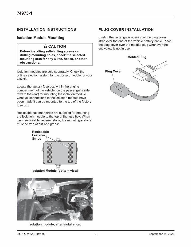
PLUG COVER INSTALLATION
Stretch the rectangular opening of the plug cover strap over the end of the vehicle battery cable. Place the plug cover over the molded plug whenever the snowplow is not in use.
Molded Plug
Plug Cover
INSTALLATION INSTRUCTIONS
Isolation Module Mounting
Isolation modules are sold separately. Check the online selection system for the correct module for your vehicle.
Locate the factory fuse box within the engine compartment of the vehicle (on the passenger's side toward the rear) for mounting the isolation module. Once all connections to the isolation module have been made it can be mounted to the top of the factory fuse box.
Reclosable fastener strips are supplied for mounting the isolation module to the top of the fuse box. When using reclosable fastener strips, the mounting surface must be free of dirt and grease.
Reclosable FastenerStrips
Isolation Module (bottom view)
CAUTIONBefore installing self-drilling screws or drilling mounting holes, check the selected mounting area for any wires, hoses, or other obstructions.
Isolation module, after installation.
Lit. No. 74328, Rev. 00 9 September 15, 2020
74973-1
LED INSTALLATION INSTRUCTIONS
Headlamp Control Module (HCM) Mounting
Locate a fl at surface within the engine compartment of the vehicle near the isolation module. If a suitable fl at surface is not accessible, cable tie the HCM to existing brackets or harnessing.
Mount the HCM so that the harness connections are wire side down.
NOTE: If possible, mount the HCM in an area that is protected from road splash.
Reclosable fastener strips and/or cable ties are supplied for mounting the HCM. When using reclosable fastener strips, the mounting surface must be free of dirt and grease.
CableTies (4)
Reclosable FastenerStrips
Headlamp Control Module(bottom view)
HCM Vehicle Battery Cable Installation
NOTE: When instructed to do so, make all snowplow battery cable connections to the auxiliary battery, if vehicle is so equipped.
NOTE: Use dielectric grease on all electrical connections to prevent corrosion. Fill receptacles and lightly coat ring terminals before assembly.
1. Turn OFF the vehicle ignition.
2. Disconnect both the NEGATIVE (–) and the POSITIVE (+) battery cables from the vehicle battery.
3. Route the supplied HCM vehicle battery cable from the battery to the 2-position mating connector on the HCM vehicle lighting harness, avoiding any sharp edges and hot or moving parts.
CAUTIONBatteries normally produce explosive gases, which can cause personal injury. Therefore, do not allow fl ames, sparks, or lit tobacco to come near the battery. When charging or working near a battery, always cover your face and protect your eyes, and also provide ventilation.• Batteries contain sulfuric acid, which burns
skin, eyes, and clothing.• Disconnect the battery before removing or
replacing any electrical components.
Lit. No. 74328, Rev. 00 10 September 15, 2020
74973-1
HCM Vehicle Lighting Harness Installation
1. Route harnesses around or through the radiator bulkhead to the HCM.
2. Make the following connections:
• 2-position connector from the vehicle lighting harness to the matching 2-position connector from the vehicle cable assembly
• Vehicle lighting harness to position "Y" on the HCM
• Single-position connector from the plug-in harness assembly to the single-position connector on the vehicle lighting harness.
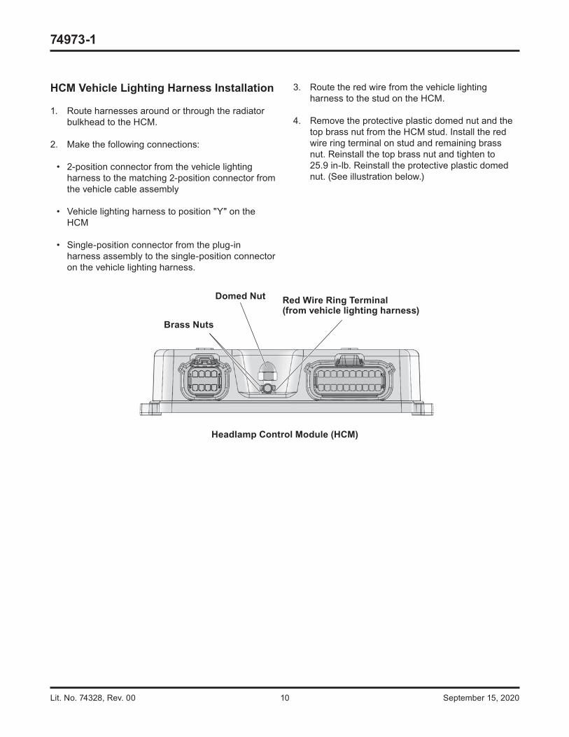
Red Wire Ring Terminal(from vehicle lighting harness)
Domed Nut
Brass Nuts
Headlamp Control Module (HCM)
3. Route the red wire from the vehicle lighting harness to the stud on the HCM.
4. Remove the protective plastic domed nut and the top brass nut from the HCM stud. Install the red wire ring terminal on stud and remaining brass nut. Reinstall the top brass nut and tighten to 25.9 in-lb. Reinstall the protective plastic domed nut. (See illustration below.)
Lit. No. 74328, Rev. 00 11 September 15, 2020
74973-1
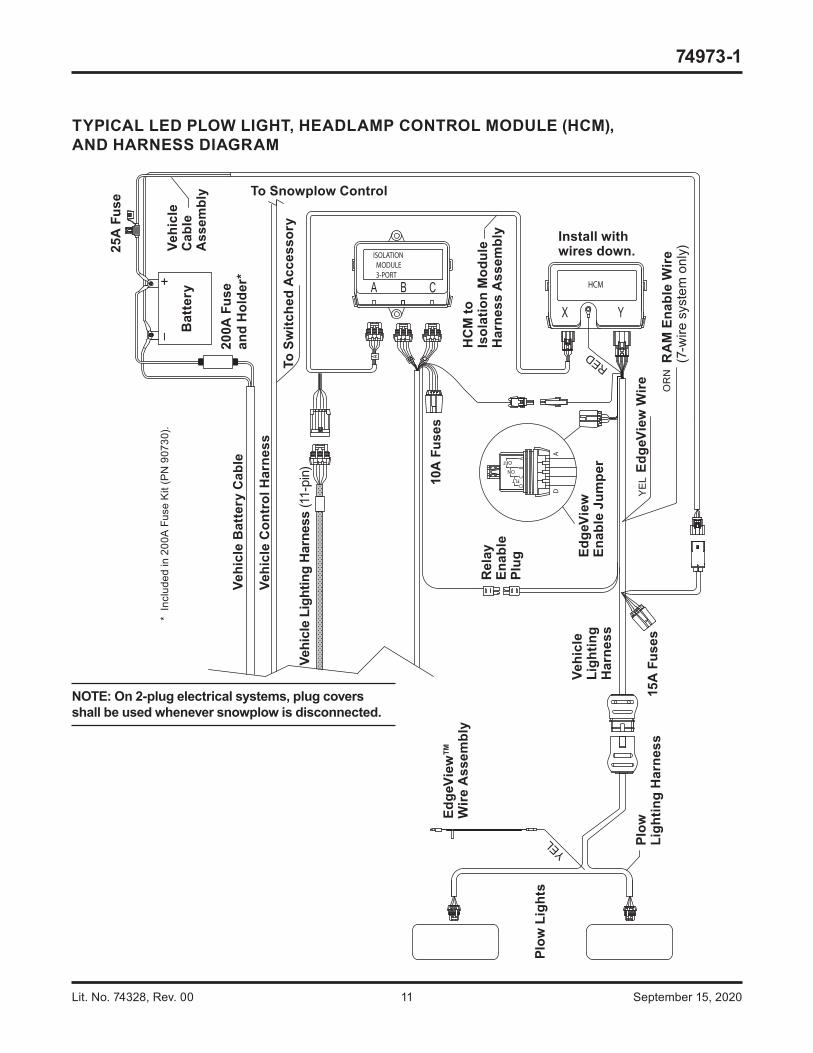
TYPICAL LED PLOW LIGHT, HEADLAMP CONTROL MODULE (HCM),AND HARNESS DIAGRAM
HC
M to
Is
olat
ion
Mod
ule
Har
ness
Ass
embl
y
Vehi
cle
Ligh
ting
Har
ness
(11-
pin)
Bat
tery
Plow
Lig
hts
Plow
Li
ghtin
g H
arne
ss
Vehi
cle
Ligh
ting
Har
ness
Vehi
cle
Con
trol
Har
ness
Vehi
cle
Bat
tery
Cab
le
Vehi
cle
Cab
leA
ssem
bly
Edge
View
™
Wire
Ass
embl
y
Edge
View
En
able
Jum
per
15A
Fus
esEd
geVi
ew W
ire
25A
Fus
e
10A
Fus
es
Rel
ayEn
able
Plug
To Snowplow Control
To S
witc
hed
Acc
esso
ry
YEL
RED
OR
N
YE
L
200A
Fus
e an
d H
olde
r*
RA
M E
nabl
e W
ire(7
-wire
sys
tem
onl
y)
* In
clud
ed in
200
A F
use
Kit
(PN
907
30).
Install withwires down.
NOTE: On 2-plug electrical systems, plug covers shall be used whenever snowplow is disconnected.
Lit. No. 74328, Rev. 00 12 September 15, 2020
74973-1
PLUG COVER INSTALLATION
Stretch the rectangular opening of the plug cover strap over the end of the HCM vehicle lighting harness. Place the plug cover over the molded plug whenever the snowplow is not in use.
Molded Plug
Plug Cover
BATTERY CONNECTIONS
NOTE: Use cable ties to secure cable assemblies and control and lighting harnesses away from any sharp edges and hot or moving parts.
NOTE: Follow OEM battery cable connection recommendations when attaching to the battery.
1. Make the following attachments to the POSITIVE (+) battery terminal:
• POSITIVE (+) OEM cable assembly
• Red 8" cable from fuse holder
• Red cable from headlamp control module power cable.
2. Make the following attachments to the NEGATIVE (–) battery terminal:
• NEGATIVE (–) OEM cable assembly
• Black vehicle battery cable
• Black cable from headlamp control module power cable.
HCM TO ISOLATION MODULE HARNESS INSTALLATION
1. Make the following connections:
• 10-position connector to port A of the isolation module
• 8-position connector to port X of the HCM.
2. As needed, cable tie harnesses away from any sharp, hot, or moving parts.
Lit. No. 74328, Rev. 00 13 September 15, 2020
74973-1
CHANGING BLADE-EDGE ILLUMINATION MODE
On snowplows equipped with LED headlamps, the EdgeView™ technology feature off ers three modes for blade-edge illumination. The factory default setting is ON.
To change the blade-edge illumination mode, remove the cover from the fuse holder located near the "Y" port of the headlamp control module installed in the vehicle engine compartment.
Remove the jumper fuse from the fuse holder and re-insert it in the desired mode position as shown below. Replace the fuse holder cover.
HEADLAMPCONTROL MODULE
Fuse Holder and Cover
Headlamp Control Module
Default – ON:Blade edge lights illuminate when plow has power.
FLT: Blade edge lights illuminate when blade is in FLOAT mode.
OFF: Blade edge lights disabled.
Jumper Fuse
PLOW-SIDE EdgeView LIGHTING CONNECTIONS
The EdgeView FLOAT (FLT) mode activation function will require a second plow-side electrical connection.
1. On the plow-side LED lighting harness, locate the yellow wire cable tied to the body of the harness near the "Y" section.
2. Strip the end of the yellow wire and insert stripped wire end into the pre-installed insulated butt connector on the supplied EdgeView wire assembly.
3. Crimp the connection and heat seal the insulated splice.
4. Remove the snowplow hydraulic unit cover. Route the EdgeView wire assembly along the snowplow structure to the snowplow hydraulic unit, and cable tie wires as needed.
5. Locate the solenoid on the snowplow hydraulic unit that is activated during the snowplow Lower/Float function. Refer to the Mechanic's Guide or snowplow manufacturer's website for further information.
6. Plug the bullet terminal on the end of the supplied EdgeView wire assembly into the receptacle on the corresponding solenoid wire. If a receptacle is not found on the correct solenoid wire, remove the bullet terminal from the EdgeView wire assembly and splice the end of the EdgeView wire into the correct solenoid wire.
7. Cable tie extra wire length to the snowplow assembly and reinstall the hydraulic unit covers.
NOTE: EdgeView light will turn ON or OFF approximately 5 seconds after EdgeView Mode is activated or canceled.
The company reserves the right under its product improvement policy to change construction or design details and furnish equipment when so altered without reference to illustrations or specifi cations used. This equipment manufacturer or the vehicle manufacturer may require or recommend optional equipment for snow removal. Do not exceed vehicle ratings with a snowplow. The company off ers a limited warranty for all snowplows and accessories. See separately printed page for this important information. The following is an unregistered (™) trademark of Douglas Dynamics, LLC: EdgeView™.