Page 1
PLMN
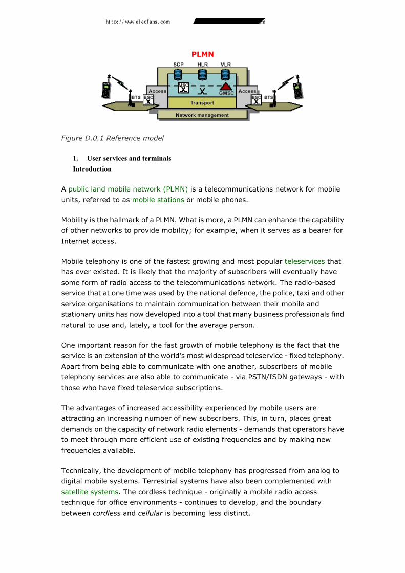
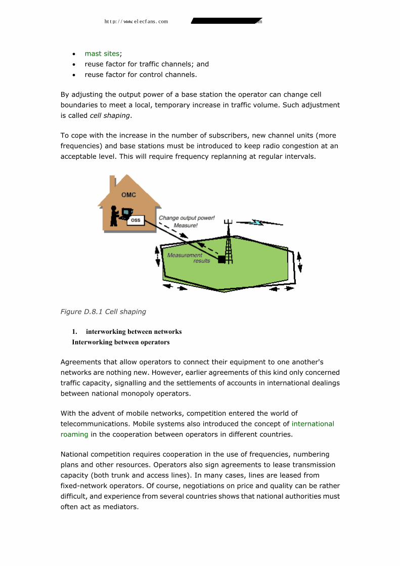
Figure D.0.1 Reference model
1. User services and terminals Introduction
A public land mobile network (PLMN) is a telecommunications network for mobile
units, referred to as mobile stations or mobile phones.
Mobility is the hallmark of a PLMN. What is more, a PLMN can enhance the capability
of other networks to provide mobility; for example, when it serves as a bearer for
Internet access.
Mobile telephony is one of the fastest growing and most popular teleservices that
has ever existed. It is likely that the majority of subscribers will eventually have
some form of radio access to the telecommunications network. The radio-based
service that at one time was used by the national defence, the police, taxi and other
service organisations to maintain communication between their mobile and
stationary units has now developed into a tool that many business professionals find
natural to use and, lately, a tool for the average person.
One important reason for the fast growth of mobile telephony is the fact that the
service is an extension of the world's most widespread teleservice - fixed telephony.
Apart from being able to communicate with one another, subscribers of mobile
telephony services are also able to communicate - via PSTN/ISDN gateways - with
those who have fixed teleservice subscriptions.
The advantages of increased accessibility experienced by mobile users are
attracting an increasing number of new subscribers. This, in turn, places great
demands on the capacity of network radio elements - demands that operators have
to meet through more efficient use of existing frequencies and by making new
frequencies available.
Technically, the development of mobile telephony has progressed from analog to
digital mobile systems. Terrestrial systems have also been complemented with
satellite systems. The cordless technique - originally a mobile radio access
technique for office environments - continues to develop, and the boundary
between cordless and cellular is becoming less distinct.
http://www.elecfans.com 电子发烧友 http://bbs.elecfans.com 电子技术论坛
Page 2
Mobile telephony is advancing worldwide at a time when liberalisation is in full swing.
For the majority of countries, deregulation and privatisation increase competition as
the number of operators increases. Different systems, aimed at promoting mobility,
operate in parallel in the same geographical area or in the same market. Analog and
digital mobile systems, cordless systems and satellite systems are all able to satisfy
user demand for mobile telecommunication in various ways.
D.1.1.1 Mobility
Mobility in a public telecommunications network is no unequivocal concept. (See
Volume 1, Chapter 6, Subsection 6.2.4.) We differentiate between portability,
movability and (complete) mobility.
Portability represents the simple case in which only the terminal is moved and then
connected again at another point in the network. Movability implies that the
subscriber moves his personal access; for example, when logging onto a data
network from different network positions. Mobility refers to the state of complete
ambulatory capability in which both the terminal and subscriber access can be
moved, while the network automatically keeps track of all movement. In other
words, this means both terminal and service mobility.
Mobility requires radio access via base (or radio base) stations. The physical access
in a mobile network is arranged to enable a terminal to connect itself anywhere in
the network and move about while a call is in progress. (Of course, the subscriber's
subscription must be available at all access points.) This movability presupposes
specially designed access ("cells" instead of connection points). It also requires that
the terminal be able to maintain continuous radio contact with the network.
D.1.1.2 Primary PLMN functions - Main network elements
It is necessary to be somewhat familiar with the specialised terminology to
understand mobile networks and their functions. Examples of basic concepts include
location updating, roaming, handover and paging. To elucidate these concepts and
the handling of mobile traffic, we should have used animated illustrations. For
practical reasons, we must leave the animation to the reader's imagination when we
refer to Figure D.1.1,which illustrates the salient elements of a fixed network and of
a PLMN.
Mobile networks require functions for network intelligence, even when handling
"ordinary" calls. Figure D.1.1 shows two of these functions: the home location
register (HLR) and the visitor location register (VLR). The figure also makes clear
that access to the PLMN is significantly different from access to fixed networks. Each
base station controller (BSC) includes a switching function allowing it to switch to
another base station as the terminal moves (roaming). In the figure, imagine the
terminal having moved from location area 1 (LA1), through LA2, to LA3, where it
http://www.elecfans.com 电子发烧友 http://bbs.elecfans.com 电子技术论坛
Page 3
has been called via the associated BSC. The next destination is LA4. Such
movement also involves a number of mobile switching centres (MSCs).
Figure D.1.1 Comparison of a fixed network and a PLMN having cells grouped in
location areas (LA)
D.1.1.3 An orientation - Common concepts
The following concepts are described in this section:
• Cells and base stations - Multiple access
• Radio channels between base stations and mobiles - Control channels and
traffic channels
• Attachment and detachment
• Roaming
• Registration and paging - Location area
• Locating and handover
The various network elements - MSC, BTS, HLR, VLR - are clarified in more detail in
Chapter 2, Section 2.3.
Cells and base stations - Multiple access
Radio access offers subscribers a number of radio channels for communication.
However, radio channels are in short supply. To effectively utilise the frequency
spectrum allocated for use by mobile subscribers, every radio channel should be
reusable, which requires well-defined and separate geographical areas that have
http://www.elecfans.com 电子发烧友 http://bbs.elecfans.com 电子技术论坛
Page 4
access to a range of frequencies. Such areas of service are referred to as cells. The
nomenclature has given rise to the term cellular system that we find in a system
name such as personal digital cellular (PDC).
The number of radio channels in a cell is significantly less than the number of
mobiles, since - in the normal case - only a minority of the mobiles are active at the
same time. The technique used to assign idle traffic channels to calling or called
mobiles is referred to as multiple access. (See also Volume 1, Chapter 5, Section
5.10.) Three variants of multiple access are described in Chapter 4, Subsections
4.3.5 - 4.3.7, of this Part.
Base stations use either omnidirectional or directional antennas. The antenna of an
omnidirectional cell radiates (more or less) an equally strong signal in all horizontal
directions, thereby covering a circular area. A mobile station located in this area will
normally experience good radio contact with the base station. The circle's radius can
be modified by changing the output power of the base station, which in most cases
is done in connection with cell planning (see Chapter 10, Section 10.5). As a rule,
maximum cell size is determined by the mobile's available output power.
Figure D.1.2 Hexagonal patterns are easy to work with
Figure D.1.2 shows a system made up of omnidirectional cells. The figure also
demonstrates the origination of the well-known hexagonal pattern. Hexagonal
patterns are easy to work with: graphically, geometrically and logically. However,
since the hexagonal model provides an idealised representation of coverage one
must always complement this model with actual coverage measurements.
A base station that uses three directional antennas, where each antenna covers an
angle of 120°, has three sector cells around it. Figure D.1.3 illustrates the
appearance of the corresponding cell pattern.
It is not always necessary to have three sector cells together. Occasionally, one
sector cell will suffice; for example, when covering a section of a road or highway.
The transmitters of each of the cells have their own frequencies. Cell pattern
planning is closely related to the use and reuse of frequencies. (See Chapter 5,
Subsection 5.2.1.)
http://www.elecfans.com 电子发烧友 http://bbs.elecfans.com 电子技术论坛
Page 5
Figure D.1.3 Three sector cells
Radio channels between base stations and mobiles
The mobile telephony service is assigned special operating frequency ranges (which
vary depending on the country and the standards employed). These frequency
ranges are in turn subdivided into radio channels, commonly 25-30 kHz wide
(channel separation). Duplex mode is employed for traffic over radio access,
meaning that the base stations and the mobiles must be capable of simultaneous
transmission and reception, requiring two frequency ranges sufficiently separated
from one another. The separation between them is referred to as the duplex
separation; its size, determined by technical factors, varies as a function of the
frequency range being used. The combination of two frequencies (or portions of
frequencies) constitutes a duplex radio channel. As an example, Figure D.1.4 shows
frequency assignment and utilisation for the NMT 450 mobile telephone system.
The channels of a mobile network are divided into two primary groups: control
channels and traffic channels.
• Every cell employs at least one channel as a control channel, on which the
base station continuously transmits an identifying signal that is used by the
mobiles to lock into that particular cell. Control channels are also used for
paging calls; if the called mobile is in the cell, it will respond over the same
(or another) channel. The number of control channels in a cell varies as a
function of the access technique employed and the expected call intensity.
Figure D.1.4 Frequency range for NMT 450
http://www.elecfans.com 电子发烧友 http://bbs.elecfans.com 电子技术论坛
Page 6
• After having completed call connection signalling, the mobile is assigned
another channel - a traffic channel - for the call. The number of traffic
channels in a cell varies with the cell's expected traffic intensity.
Control channels and traffic channels are also referred to as logical channels. These
logical channels are mapped onto physical channels.
A physical channel can be a radio broadcasting frequency, a pair of frequencies
(including duplex separation) in an analog mobile system or a time slot on a pair of
frequencies in a digital mobile system.
Traffic channels are addressed in greater detail in Chapter 4, Subsection 4.3.5.
Control channels are described in Chapter 7.
Attachment and detachment
As soon as a mobile is turned on, it establishes contact with the network. It thus has
"access" to the network, and the network registers its movements.
A user can turn his mobile off occasionally to conserve battery power. Since it would
not make much sense to attempt to call an idle mobile, the system includes
functionality to keep track of whether the mobile is ON (attachment) or OFF
(detachment).
Roaming
Regardless of its location, a mobile that is turned on must maintain constant radio
contact with the network. Both the network and the mobile include special
functionality for this purpose: the roaming function.
Location updating and paging - Location area
A terminal in a fixed network is connected to a fixed access point, which is also
associated with a subscriber number. Information about this association is stored in
the local exchange responsible for the particular access point. If a terminal is moved,
it will normally be assigned a new number depending on which local exchange it is
moved to. This movability places no demands on the network in terms of routing or
connection control.
Fixed access points do not exist in the world of mobile networks. When a mobile is
called, the network must be able to determine its position, and that requires special
intelligence. Registration (or location updating) is the intelligent network function
that keeps track of the mobile's position. Paging is the actual search operation
performed in all or some of the network cells.
http://www.elecfans.com 电子发烧友 http://bbs.elecfans.com 电子技术论坛
Page 7
Figure D.1.5 Location area
Radio resources would be greatly overworked if, for every incoming call, the paging
function were activated to locate the position of the called mobile all over the
network. The solution lies in forcing the mobiles to report their positions, that is, to
register. The question is: How often should a mobile report - upon entering a new
cell or less frequently? The size of the area within which the mobile need not register
becomes a trade-off between location updating and paging. Updating locations per
cell would load the network with too many registrations, while a large area - for
example, an MSC service area - might very well load the network with too many
"paging assignments". The group of cells in which a mobile need not register is
referred to as its location area.The location area can correspond to a BSC service
area (as shown in Figure D.1.5) but can also consist of cells from several different
BSC service areas located in the same MSC service area.
While the use of a traffic channel is related to specific, non-adjacent cells, call
channels are a common resource for a given location area. A location area must not
be made so large as to allow the number of calls in the area to cause call-channel
congestion.
Since the registration and paging functions require network intelligence, they are
also addressed in Chapter 6, Section 6.2.
Locating and handover
The channel used for a call - or for control - must be capable of being switched from
cell to cell as the mobile traverses the cells. The system must be able to detect
whether or not switching is necessary (normally coinciding with the fact that signal
strength has dropped below a given value or the signal-to-noise ratio has become
unsatisfactory). This function is referred to as locating.The technical term for
actually switching from cell to cell - which preferably occurs without the user
noticing it - is handover.
Handover is addressed in greater detail in Chapter 3 (switching aspects) and in
Chapter 5 (transmission aspects).
http://www.elecfans.com 电子发烧友 http://bbs.elecfans.com 电子技术论坛
Page 8
Services
The basic idea of mobile services is to offer the moving subscriber the same services
that are offered to fixed-network subscribers. Subscriber movement requires
sophisticated solutions to maintain service continuity throughout the network.
Information on the individual subscriber's access to a specific service and on the
status of this service must be transmitted between the exchanges of the mobile
network in step with the movement of the subscriber.
D.1.2.1 Telephony
The most important function of a mobile network is the creation of a good and
dependable telephone service. Under favourable radio transmission conditions, the
quality of the telephone service is comparable with fixed-network telephony. Digital
mobile networks are capable of delivering telephony of varying quality, depending
on the voice-coding method employed over radio access. The GSM digital mobile
system uses the terms "full-rate coding" (13 kbit/s) and "half-rate coding" (6.5
kbit/s).
D.1.2.2 Data
The speed normally used by GSM is 9.6 kbit/s, but higher speeds are being
developed (see Chapter 2, Subsection 2.4.4).
The use of modems enables analog systems to offer data services with bit rates up
to 19.2 kbit/s.
D.1.2.3 Telefax
All larger mobile systems support Group 3 telefax.
D.1.2.4 Supplementary services
Mobile network supplementary services are similar to their counterparts in the fixed
network, even if services such as call barring require a greater number of variations.
A subscription for official use can be barred so that incoming calls are not accepted;
for instance, when the mobile is used on an assignment in another country. This
protects the company against the risk of having to pay the high cost of private calls
being made from home to the mobile.
D.1.2.5 Emergency call services
Many mobile networks offer an emergency call service. All the user has to do in an
emergency situation is contact an emergency centre - no knowledge of the
telephone numbers of different centres in the area is required. Even black-listed
http://www.elecfans.com 电子发烧友 http://bbs.elecfans.com 电子技术论坛
Page 9
mobiles and mobiles that are ordinarily unable to pass authentication can use this
service.
D.1.2.6 Messaging services
Messaging services are particularly important in increasing accessibility in a PLMN,
because terminals can be turned off or can be in an area where buildings or hills
create radio shadows. Voice mail, telefax and short message service (SMS) are
examples of messaging services.
SMS allows callers to leave short text messages (GSM allows up to 160 characters).
A message that cannot be delivered immediately will be stored in a short-message
service centre until the mobile can be reached.
Service development
As is evident from Subsection 1.2.2, mobile networks have little data transmission
capacity. Today's analog mobile systems can have greater capacity than their digital
counterparts (19.2 kbit/s for analog and 9.6 kbit/s for digital systems). The
explosive development of mobile communication and Internet-type data
communication has led to demand for significant enhancement of the data
communication capabilities of mobile systems.
The need for video transmission including high resolution can lead to demands for
even greater capacity, up to 384 kbit/s or 2 Mbit/s. In principle, this would result in
mobile systems made up of three transfer-rate classes:
• Today's systems, which are optimised for the transfer of voice.
• Upgraded versions of today's systems having significantly improved data -
transfer capacity - slightly more than 100 kbit/s.
• New systems that complement existing systems. One example is the
universal mobile telecommunication system (UMTS).
The aim of the UMTS is to enable mobile access to offer the same range of services
as those offered by fixed access while providing the same quality. The UMTS and the
upgrading of today's systems are addressed in more detail in Chapter 2 (see Section
2.6 and Subsection 2.4.4).
D.1.3.1 Intelligent mobile terminals
A mobile system is ordinarily considered as simply a "transporter of bits" as far as
data communication is concerned. Any intelligent communication with an Internet
Web server, for example, is managed by a computer connected to the mobile
system. This situation will change as "smarter" mobile terminals appear on the
http://www.elecfans.com 电子发烧友 http://bbs.elecfans.com 电子技术论坛
Page 10
market. The advent of small hand-held computers having built-in communications
ability is a step in this direction.
The trend just described implies that the PLMN - from a data communications point
of view - will develop from being a bearer network into a network that includes
built-in, highly advanced teleservices and value-added services; for instance,
services that allow a mobile to be used as a handy tool for making payment
transactions. (See also Section 1.5, in particular Figure D.1.7.)
Security
Networks that utilise radio communications are especially sensitive to unauthorised
use of terminals and to tapping along the radio path. Mobile networks therefore
require the institution of special security measures. Both the user and the network
operator must be protected against any unauthorised intrusion by a third party. This
protection can either consist of a supplementary service selected by the user; for
example, a smart card (with a personal code) for systems that use such cards, or of
various network functions such as encryption and authentication.
The following functions have been enhanced to protect the network:
• authentication system that protects against unauthorised use of the
network's services;
• encryption to protect against unauthorised tapping of radio access;
• terminal identification that protects against the use of stolen mobiles; and
• temporary telephone numbers that protect against unauthorised access to a
mobile's identity.
Security is addressed in greater detail in Chapter 6, Section 6.4.
http://www.elecfans.com 电子发烧友 http://bbs.elecfans.com 电子技术论坛
Page 11
Terminals
Figure D.1.6 The most important key functions on a mobile telephone
The development of the mobile telephone has been characterised by two dominant
trends: size reduction and increased intelligence. Both trends have the same origins,
namely the endeavour to make components ever smaller and more advanced and
the constant development and refinement of the design. Also, the mobile telephone
has already passed three initial phases: the car-mounted model, the portable model
and the current pocket model.
In digital networks, the mobile assists in the handover process by continuously
measuring base station signal strength and then reporting the measured values to
the network. The mobile's ability to control the handover process (mobile-controlled
handover) will mark the next step in its development (see Chapter 5, Section 5.4).
A pocket telephone has a number of facilities. The most common are:
• alphanumeric display;
• memory for many abbreviated numbers;
• signal strength indicator;
• battery indicator; and
• electronic lock.
The mobile office is a concept that has developed in step with the increase in
teleworking. In addition to the mobile telephone, an important tool is the laptop PC
which can be equipped with a modem card. The laptop can then be connected
http://www.elecfans.com 电子发烧友 http://bbs.elecfans.com 电子技术论坛
Page 12
directly to a mobile telephone's modem port. The portable fax is another terminal
that can be used over a PLMN.
The development towards more advanced terminals as described in Section 1.3.1 is
illustrated in Figure D.1.7.
Figure D.1.7 The development of PLMN terminals from simple mobile telephones
into intelligent mobile terminals
1. standardisation Standardisation organisations
The most important standardisation efforts in the field of mobile systems have been
made by the ITU-T, which has published a large number of mobile network
recommendations. Recommendation Q.1001, "General aspects of Public Land
Mobile Networks", provides an overview of the definitions, architecture and services
related to a public, nationwide, mobile network. Recommendations also deal with
other important areas, such as numbering plans, grade of service (GoS), signalling
and interworking between networks. ITU-R, the ITU's "radio sector", discusses and
regulates the use of the radio frequency spectrum, a limited natural resource
required by mobile networks for their operation.
Another influential standards organisation in the field of mobile systems is the
European Telecommunications Standardisation Institute (ETSI). ETSI has
developed a specification for the global system for mobile communication (GSM)
and has specified a digital system for cordless telephony, digital enhanced cordless
telecommunications (DECT), and a paging system referred to as European radio
message system (ERMES).
Other important standardisation organisations are the Japanese RCR and TTC and
the North American ANSI, EIA and TIA. North American operators are assigned
frequencies by the Federal Communications Commission (FCC ).
http://www.elecfans.com 电子发烧友 http://bbs.elecfans.com 电子技术论坛
Page 13
Voice coding in mobile networks
Due to the scarcity of available frequency bands, all digital mobile systems use
some hybrid form of coding that enables bit rates to be reduced to a level far below
the 64 kbit/s achieved in PCM coding. Hence, all systems use voice-block coding
instead of pure waveform coding. Each voice block (20 milliseconds in GSM) is
analysed and compared with the subsequent block (and with references), and then
parameterised and coded. The long blocks enable lower bit rates but they also result
in delays that create echo problems. Well-balanced echo cancellation is therefore of
great importance to the voice quality in connections involving digital mobile
systems.
D.2.2.1 Human speech
Human speech contains a great deal of redundant information. We can reduce this
redundancy through the use of speech analysis and transfer only that portion of
speech required to reproduce the information at the receiving end.
Figure D.2.1 A model of the human organs of speech
The vocal cords vibrate and create sound of varying frequencies. The sound is
modified when passing through the organs of speech, which function as a frequency
filter.
D.2.2.2 GSM voice coding
The following is a brief description of the voice coding employed by the mobiles of a
GSM system. A number of electronic filters are used to simulate the operation of the
human organs of speech and to extract the vocal cords' original frequencies, called
excitation sequences.
http://www.elecfans.com 电子发烧友 http://bbs.elecfans.com 电子技术论坛
Page 14
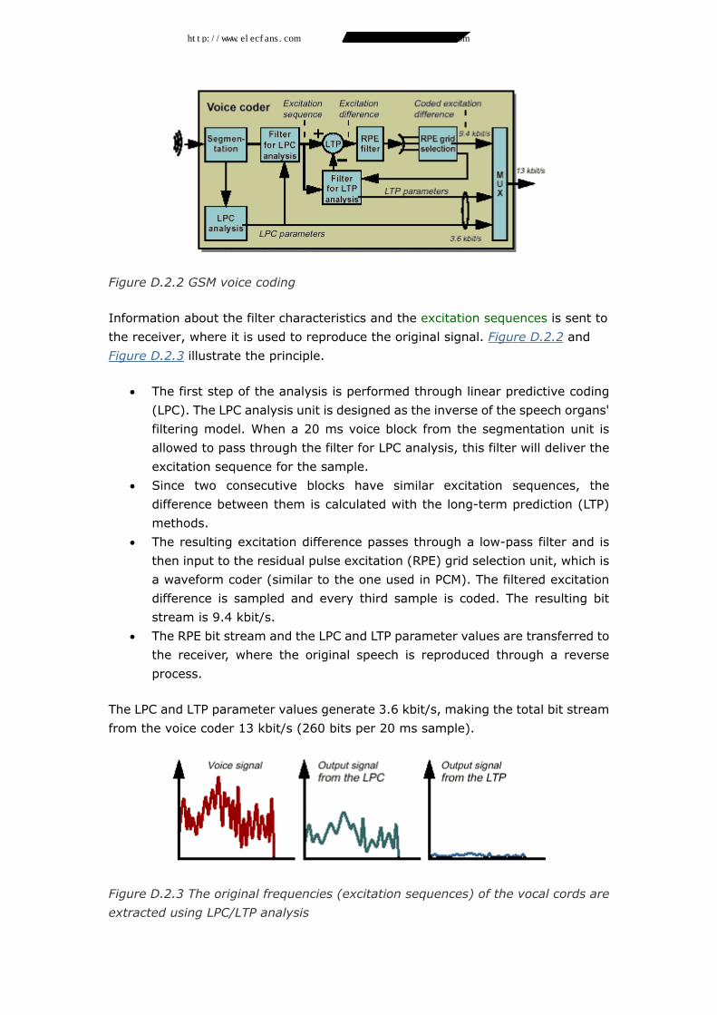
Figure D.2.2 GSM voice coding
Information about the filter characteristics and the excitation sequences is sent to
the receiver, where it is used to reproduce the original signal. Figure D.2.2 and
Figure D.2.3 illustrate the principle.
• The first step of the analysis is performed through linear predictive coding
(LPC). The LPC analysis unit is designed as the inverse of the speech organs'
filtering model. When a 20 ms voice block from the segmentation unit is
allowed to pass through the filter for LPC analysis, this filter will deliver the
excitation sequence for the sample.
• Since two consecutive blocks have similar excitation sequences, the
difference between them is calculated with the long-term prediction (LTP)
methods.
• The resulting excitation difference passes through a low-pass filter and is
then input to the residual pulse excitation (RPE) grid selection unit, which is
a waveform coder (similar to the one used in PCM). The filtered excitation
difference is sampled and every third sample is coded. The resulting bit
stream is 9.4 kbit/s.
• The RPE bit stream and the LPC and LTP parameter values are transferred to
the receiver, where the original speech is reproduced through a reverse
process.
The LPC and LTP parameter values generate 3.6 kbit/s, making the total bit stream
from the voice coder 13 kbit/s (260 bits per 20 ms sample).
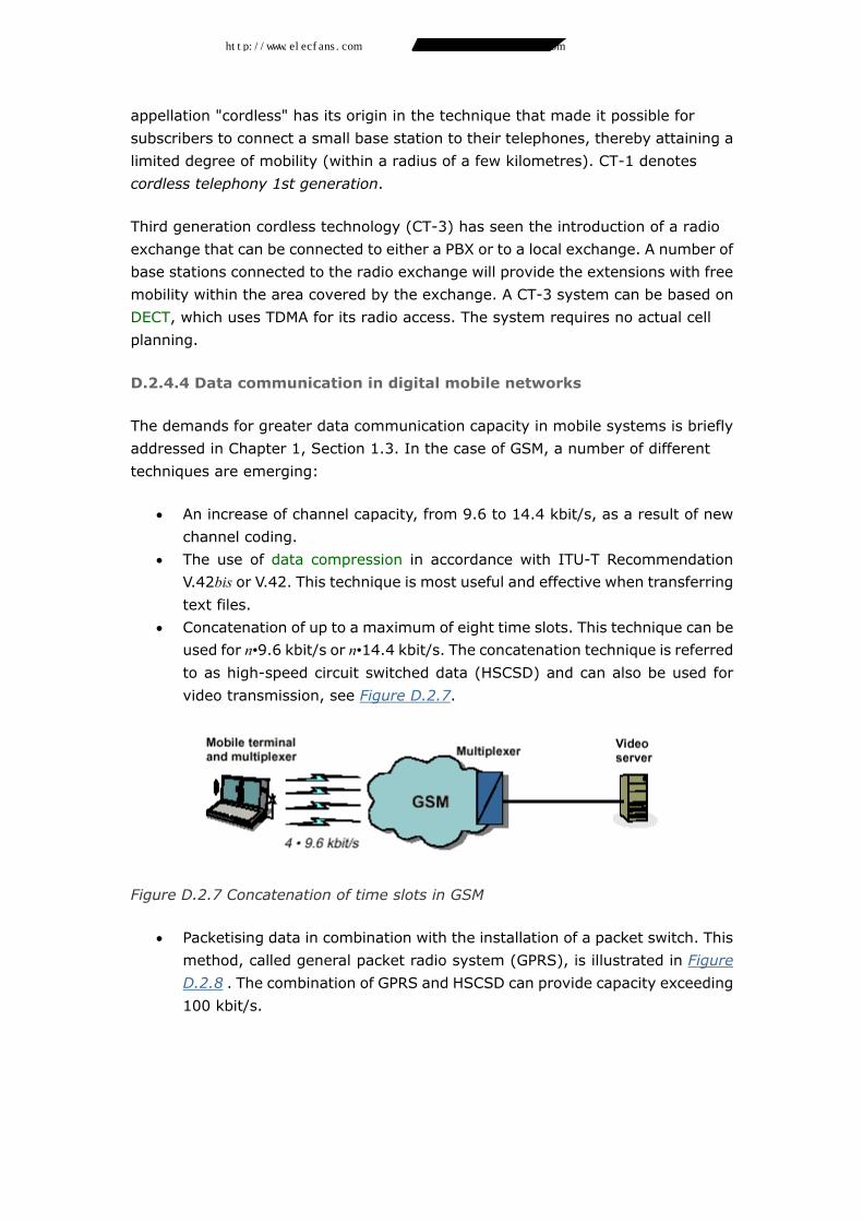
Figure D.2.3 The original frequencies (excitation sequences) of the vocal cords are
extracted using LPC/LTP analysis
http://www.elecfans.com 电子发烧友 http://bbs.elecfans.com 电子技术论坛
Page 15
Network elements
For the most part, the same types of network element are found in all mobile
networks, even if they are named differently in different standards. In Figure
D.2.4,we use GSM as an example.
Figure D.2.4 GSM network elements
D.2.3.1 Network elements for (user) traffic
• MS: A mobile station can be a mobile telephone, a fax having radio access or
a laptop computer equipped with a radio modem.
• BTS: A base transceiver station contains equipment for transmission and
reception, antennas for one or more cells, plus equipment for
encryption/decryption and signal strength measurement and for
communication with the BSC.
• BSC: A base station controller, also referred to as the radio switch, sets up
the radio channels for traffic and for signalling to the MSC (see below) and
monitors the access network portion of the connection. A BSC also performs
traffic concentration and handles handover between the base stations that it
controls. BSCs are only found in the GSM standard. In other standards, the
MSC also handles radio switch functions.
• MSC: A mobile switching centre is a switching node having the specialised
functions required by mobile networks, notably those relating to handover
between MSCs and between different PLMNs. An MSC can be likened to the
local exchange of a fixed network, although it does not have any fixed
http://www.elecfans.com 电子发烧友 http://bbs.elecfans.com 电子技术论坛
Page 16
subscribers (at least not in the case of GSM). A PLMN can have one or several
MSCs, depending on the size of the network and the number of subscribers.
The cells whose base stations are controlled by a particular MSC constitute
an MSC service area.
• A gateway MSC (GMSC) is a specialised MSC that serves as an interface to
other networks. All connections to and from mobile networks pass through a
GMSC (more than one unit can be found within one and the same network).
A GMSC need not handle subscriber data but must be capable of handling
different signalling standards for its communication with other networks.
Charging and settlement of accounts between networks are also functions of
the GMSC.
A GMSC represents a mobile network vis-à-vis other networks.
Fixed-network connections are performed at the national or international
level of the PSTN/ISDN, where a PLMN can be identified in the same manner
as any other operator network.
• Short message service centre (SMS-C): Messaging systems (in the form of
voice mailboxes for short messages and fax mailboxes) are used to increase
accessibility in a PLMN.
D.2.3.2 Network elements as databases
• HLR: Mobile subscribers must be permanently registered somewhere in the
system. In a fixed network, every subscriber belongs to a local exchange; a
mobile subscriber belongs to the network. That is why mobile networks
include one or more databases (HLRs) for permanent storage of subscriber
data. The HLR keeps continuous track of the location of the subscriber -
whether he is in an MSC service area or in a different PLMN. This information
is used by the GMSC when receiving a call from another network. An HLR can
be a stand-alone network element or built into an MSC.
• VLR: An MSC only handles temporary subscribers, namely those who happen
to be in the MSC service area at a given point in time. Data pertaining to
these subscribers is stored in a VLR, which can be a stand-alone network
element used by several MSCs. Ordinarily, though, each MSC has its own VLR.
The VLR keeps track of the service area cells within which a mobile can be
located and is constantly informed of whether the mobile is ON or OFF.
• AUC: The authentication centre stores security information - for example,
encryption keys - for all subscribers of the network. The AUC is also used for
encryption/decryption.
• EIR: The equipment identity register stores information on the identity of
every mobile. The EIR is used to check that a mobile is not reported as stolen
or barred for some other reason.
D.2.3.3 Network elements for additional network intelligence
http://www.elecfans.com 电子发烧友 http://bbs.elecfans.com 电子技术论坛
Page 17
As in the case of the service control points (SCPs) and service switching points
(SSPs) of fixed networks, PLMN operators also have need of such network
intelligence nodes. This intelligence enables them to maintain short lead times when
creating new services and customer-specific applications.
D.2.3.4 Network elements for operation and maintenance
The operation and maintenance centre (OMC) accommodates two network
elements: an operations support system (OSS) and a network management system
(NMS). Both are connected to other network elements in the core and access
networks via a separate X.25 network.
D.2.3.5 Network elements for signalling
Since a GSM network utilises signalling system No. 7 (SS7), either integrated or
stand-alone signal transfer points (STPs) are required.
D.2.3.6 Network elements for transport and transmission
With the exception of transmission over radio access, mobile network standards
contain no guidance as to how network elements are to be interconnected from a
transmission point of view. Ordinarily, plesiochronous digital hierarchy (PDH),
synchronous digital hierarchy (SDH) or synchronous optical network (SONET)
systems are used.
Mobile telephony standards
The following main features distinguish the different types of PLMN from one
another:
• the technique used for radio access (TDMA, FDMA, or CDMA - see Chapter 4,
Subsections 4.3.5 - 4.3.7);
• the disposition of functionality between the network and the mobile (for
example, whether the network or the mobile is responsible for channel
selection); and
• the design of the access network (in some networks, the control of access
network resources and of the air interface resides in the access network; in
other networks, these functions reside in the MSC).
There are currently seven different cellular mobile network standards: three analog
and four digital.
D.2.4.1 Analog mobile networks
http://www.elecfans.com 电子发烧友 http://bbs.elecfans.com 电子技术论坛
Page 18
Analog mobile networks are characterised by the fact that control channels and
traffic channels are analog. Both voice (commonly at 3 kHz) and data are
frequency-modulated on a carrier. Today's analog network standards are:
• NMT - Nordic mobile telephony;
• AMPS - American mobile phone system; and
• TACS - Total access communication system
Figure D.2.5 Analog mobile network standards
NMT
NMT was specified by the Nordic telecommunications administrations and was the
first commercially operated public mobile network (1981). Two variants exist: NMT
450 and NMT 900. The numbers relate to the frequency bands used. NMT 900,
introduced in 1986 as a result of the fact that the number of NMT 450 channels was
insufficient, also offers some international roaming functionality. NMT has been
implemented in Europe, the Middle East and Asia.
AMPS
AMPS is a notable mobile network standard that was specified by the US consortium
TIA/EIA/ANSI. The air interface standard is referred to as EIA/TIA-553. The first
AMPS network became operational as early as 1984 in the US, and in 1988, the
standard was expanded to comprise a wider frequency band, E-AMPS. AMPS
networks are found in the Americas, Australia and in Asia.
TACS
TACS is a modified version of AMPS; its frequency band is somewhat higher. The
modification was made with the British market in view, where the standard was
operational in 1985. TACS also received a wider frequency band in 1988, E-TACS.
Since that time, TACS has spread to many countries around the world.
D.2.4.2 Digital mobile networks
http://www.elecfans.com 电子发烧友 http://bbs.elecfans.com 电子技术论坛
Page 19
Digital mobile networks are primarily characterised by their digital traffic channels,
which means that the speech they carry is coded. However, they can include both
analog and digital control channels.
Examples of systems include:
• GSM, global system for mobile communication;
• PCS, personal communications services (IS-95, IS-136, and others);
• D-AMPS, digital AMPS, referred to earlier as ADC, American digital cellular;
and
• PDC, personal (Pacific) digital cellular, referred to earlier as JDC, Japanese
digital cellular.
Figure D.2.6 Digital mobile network standards
GSM
Both the traffic and control channels of a GSM system are digital. GSM was specified
by ETSI and went into commercial operation in 1992. The acronym GSM originally
stood for groupe spéciale mobile - the ETSI group which, in 1982, was assigned the
task of specifying a digital mobile system that should include international roaming,
open interfaces between network elements, better voice quality and certain ISDN
functionality.
Three different frequency bands - 900, 1800 and 1900 MHz - are available for GSM
systems. By and large, the corresponding standards (called GSM 900, GSM 1800
and GSM 1900) follow the same specification. GSM 1800/1900 is chiefly intended
for areas of high mobile density and is one of many ways to utilise the limited
frequency range available to mobile telephony. That is why GSM 1800/1900 makes
extensive use of microcells within umbrella cells (see Chapter 10, Subsection 10.4.4)
and why the output power from its terminals and base stations is low.
http://www.elecfans.com 电子发烧友 http://bbs.elecfans.com 电子技术论坛
Page 20
GSM networks are found all over the world.
D-AMPS
D-AMPS is a version of AMPS that has been extended to employ digital traffic
channels. Thanks to the access technique used (TDMA, three time slots) one 30 kHz
channel has capacity for three traffic channels at full coding rate. The extended
standard, referred to as IS-54, thus enables D-AMPS to include both analog and
digital traffic channels in one and the same network, indeed, even in the same cell.
Users of such a mobile network experience the best GoS if their mobiles can shift
between analog and digital traffic channels even during handover. D-AMPS became
commercially available in 1991-1992 and has about the same area of distribution as
AMPS.
The extension of D-AMPS to include a digital, physical control channel that occupies
one time slot has since been specified in IS-136 rev. 0. In much the same way as in
GSM, logical control channels are mapped onto the time slot. (See Chapter 7,
Subsection 7.3.4.) The new standard also includes the two older standards. Hence,
a D-AMPS network in accordance with IS-136 rev. 0 can contain both analog and
digital traffic and control channels. Following an additional extension - with IS-136
rev. A - D-AMPS is currently specified for 1900 MHz and is referred to as 1900-AMPS.
Mobiles that use 1900 MHz need not be capable of handling analog channels, but
they should be able to use both the 800 and 1900 MHz bands (dual band).
PCS
Personal communications service (PCS) is a very open standard; it mainly specifies
a service interface. A PCS system can either be analog or digital, using cellular or a
combination of cellular and cordless techniques. Digital access can be based either
on TDMA or on IS-95 (CDMA).
PDC
PDC was specified by RCR in Japan, in cooperation with 11 manufacturers, three of
whom were non-Japanese enterprises. The system became commercially available
in 1993-1994. The air interface is open and similar to that of D-AMPS, while the
network architecture and services are more like GSM. For the time being, PDC is
only available in Asia.
D.2.4.3 Cordless systems
Cellular systems are not the only means of providing mobile telephony. Another
large group is also worth mentioning in this connection, namely cordless systems.
They have not yet been used to build complete logical networks but are primarily
employed in private networks and, increasingly, as a PSTN access method. The
http://www.elecfans.com 电子发烧友 http://bbs.elecfans.com 电子技术论坛
Page 21
appellation "cordless" has its origin in the technique that made it possible for
subscribers to connect a small base station to their telephones, thereby attaining a
limited degree of mobility (within a radius of a few kilometres). CT-1 denotes
cordless telephony 1st generation.
Third generation cordless technology (CT-3) has seen the introduction of a radio
exchange that can be connected to either a PBX or to a local exchange. A number of
base stations connected to the radio exchange will provide the extensions with free
mobility within the area covered by the exchange. A CT-3 system can be based on
DECT, which uses TDMA for its radio access. The system requires no actual cell
planning.
D.2.4.4 Data communication in digital mobile networks
The demands for greater data communication capacity in mobile systems is briefly
addressed in Chapter 1, Section 1.3. In the case of GSM, a number of different
techniques are emerging:
• An increase of channel capacity, from 9.6 to 14.4 kbit/s, as a result of new
channel coding.
• The use of data compression in accordance with ITU-T Recommendation
V.42bis or V.42. This technique is most useful and effective when transferring
text files.
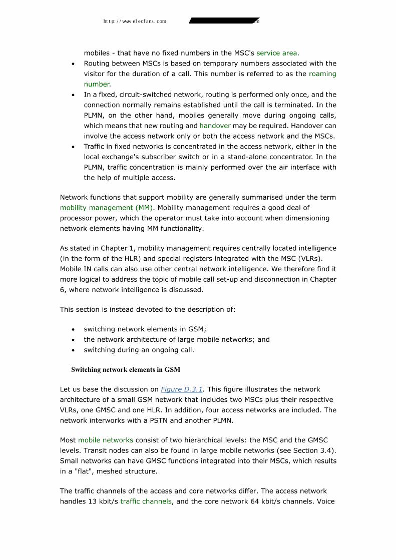
• Concatenation of up to a maximum of eight time slots. This technique can be
used for n•9.6 kbit/s or n•14.4 kbit/s. The concatenation technique is referred
to as high-speed circuit switched data (HSCSD) and can also be used for
video transmission, see Figure D.2.7.
Figure D.2.7 Concatenation of time slots in GSM
• Packetising data in combination with the installation of a packet switch. This
method, called general packet radio system (GPRS), is illustrated in Figure
D.2.8 . The combination of GPRS and HSCSD can provide capacity exceeding
100 kbit/s.
http://www.elecfans.com 电子发烧友 http://bbs.elecfans.com 电子技术论坛
Page 22
Figure D.2.8 Packet nodes implemented in GSM
Related standards
D.2.5.1 Wide area paging networks
As mentioned earlier, ETSI has standardised ERMES for WAP. The first ERMES
network was brought into operation in 1993. ERMES operates using 16 different
carriers with a bit rate of 6.25 kbit/s and includes international roaming between the
different WAP networks (WAPN). The recipient of a call in ERMES can also transmit
a response message. (See Volume 1, Chapter 6, Subsection 6.3.3.)
D.2.5.2 Mobile data networks
An example of a mobile data network - the packet-switched Mobitex - is described
in the following. Mobitex was specified by Televerket, the former National Swedish
Telecommunications Administration, and became operational in 1987. It is now
available on the American and European continents.
http://www.elecfans.com 电子发烧友 http://bbs.elecfans.com 电子技术论坛
Page 23
Figure D.2.9 A mobile data network
The network is cellular and in most cases nationwide. It provides the possibility of
creating closed user groups (CUGs), regarded as highly advantageous by the
system's most customary users - police departments, ambulance services, fire
departments and shipping and forwarding agents. Since the network is
packet-switched, individual users do not have their own physical channels
connected during "calls", which means that there is no need to dimension base
station capacity in accordance with ordinary traffic theory.
Mobile users can be connected to fixed computers via regional exchanges. Since
messages do not generally exceed 40-50 characters, and since connection set-up
times are significantly shorter than is the case in a circuit-switched network,
communication is extremely fast.
While en route to a fire, fire-engines can receive information about the situation at
the site of the fire, ambulances carrying injured persons can receive blood-group
information on the way to the hospital, and truck drivers can be directed in real time
to the right distribution centre in an unknown city.
Future standards
For several years, the ITU-T has been conducting a project aimed at setting future
mobile standards: future public land mobile telecommunications systems (FPLMTS).
The project, nowadays referred to as IMT 2000, addresses mobile systems having
broadband characteristics. UMTS (which stands for universal mobile
telecommunications system) is the designation used in Europe. UMTS should be
regarded as an extension to GSM and not as a replacement.
http://www.elecfans.com 电子发烧友 http://bbs.elecfans.com 电子技术论坛
Page 24
UMTS is specified by ETSI and the UMTS Forum. The most prominent features of the
system are a new air interface for symmetrical or asymmetrical packet traffic
capability and broader and more flexible bandwidths. It will thus be a new radio
access system capable of integration with GSM.
GSM/UMTS is structured into an access and a core network, having two different
radio access systems - GSM radio access and UMTS radio access - and a common
core. Using dual mode, mobiles can be adapted to GSM, UMTS or both.
The interface between the core and the GSM radio access is referred to as A, while
the interface between the core and the UMTS radio access is called generic radio
access network (GRAN), as shown in Figure D.2.10. The UMTS air interface is in the
2 GHz band. Three frequency alternatives - 900, 1800 and 1900 MHz - are available
to the A-interface.
It is believed that data transmission will account for an increasing portion of traffic
and that its destination will often be the Internet. (See Figure D.2.10.)
Figure D.2.10 GSM/UMTS architecture
1. switch and switching Introduction
Mobile network functions for switching and switch control use the same switching
technique as that used in PSTN/ISDN but differ in some other respects from the
corresponding fixed-network functions.
• An MSC in a mobile network only has temporary subscribers - visiting
http://www.elecfans.com 电子发烧友 http://bbs.elecfans.com 电子技术论坛
Page 25
mobiles - that have no fixed numbers in the MSC's service area.
• Routing between MSCs is based on temporary numbers associated with the
visitor for the duration of a call. This number is referred to as the roaming
number.
• In a fixed, circuit-switched network, routing is performed only once, and the
connection normally remains established until the call is terminated. In the
PLMN, on the other hand, mobiles generally move during ongoing calls,
which means that new routing and handover may be required. Handover can
involve the access network only or both the access network and the MSCs.
• Traffic in fixed networks is concentrated in the access network, either in the
local exchange's subscriber switch or in a stand-alone concentrator. In the
PLMN, traffic concentration is mainly performed over the air interface with
the help of multiple access.
Network functions that support mobility are generally summarised under the term
mobility management (MM). Mobility management requires a good deal of
processor power, which the operator must take into account when dimensioning
network elements having MM functionality.
As stated in Chapter 1, mobility management requires centrally located intelligence
(in the form of the HLR) and special registers integrated with the MSC (VLRs).
Mobile IN calls can also use other central network intelligence. We therefore find it
more logical to address the topic of mobile call set-up and disconnection in Chapter
6, where network intelligence is discussed.
This section is instead devoted to the description of:
• switching network elements in GSM;
• the network architecture of large mobile networks; and
• switching during an ongoing call.
Switching network elements in GSM
Let us base the discussion on Figure D.3.1. This figure illustrates the network
architecture of a small GSM network that includes two MSCs plus their respective
VLRs, one GMSC and one HLR. In addition, four access networks are included. The
network interworks with a PSTN and another PLMN.
Most mobile networks consist of two hierarchical levels: the MSC and the GMSC
levels. Transit nodes can also be found in large mobile networks (see Section 3.4).
Small networks can have GMSC functions integrated into their MSCs, which results
in a "flat", meshed structure.
The traffic channels of the access and core networks differ. The access network
handles 13 kbit/s traffic channels, and the core network 64 kbit/s channels. Voice
http://www.elecfans.com 电子发烧友 http://bbs.elecfans.com 电子技术论坛
Page 26
recoding between 13 and 64 kbit/s is performed in the BSC. Encryption equipment
is normally located in the base stations.
Figure D.3.1 The physical network architecture of a PLMN
Switching is performed at four levels of the structure: in the BTS, BSC, MSC and
GMSC, shown in Figure D.3.1.
Concentration is performed in the air interface, because the number of traffic
channels is limited. This concentration is controlled by the BSC, which assigns idle
traffic channels to mobiles. After decryption in the BTS, four 13 kbit/s traffic
channels are multiplexed onto one 64 kbit/s channel - normally a time slot of a PCM
link between the BTS and the BSC.
http://www.elecfans.com 电子发烧友 http://bbs.elecfans.com 电子技术论坛
Page 27
Figure D.3.2 Switching network elements in GSM
The BSC connects traffic channels between the BTS and the MSC, employing a pool
of voice coders that can be connected to the switch in the BSC. The BSC also
performs the required switching during a call in progress, as the mobile moves from
one cell to another within a BSC service area.
Ordinarily, an MSC switches 64 kbit/s traffic channels between the GMSC and one of
its BSCs. It must continuously keep track of (or be able to find out) which section of
its own service area a called mobile is in. It must also be capable of switching to
another MSC whenever a mobile moves to a cell in another MSC's service area
during an ongoing call, as described in Subsection 3.3.
A GMSC switches 64 kbit/s traffic channels between external networks and the
MSCs of its own PLMN as well as between external fixed networks and interworking
PLMNs. As mentioned earlier, GMSCs are connected to external networks at the
national or international hierarchical network levels.
When a GMSC receives a call from an external network, it must determine the MSC
(or the interworking PLMN) that is currently able to reach the called mobile - in other
words, which MSC service area or which interworking PLMN it must connect to. This
is where network intelligence enters the picture. The HLR informs the GMSC of
which MSC to use, and because the calling mobile does not have a fixed extension
to that MSC, the HLR will also provide the GMSC with a temporary routing number
http://www.elecfans.com 电子发烧友 http://bbs.elecfans.com 电子技术论坛
Page 28
to be used for signalling. This number was retrieved by the HLR from the VLR
involved. The roles of the HLR and VLR are described in more detail in Chapter 6
Reswitching during a call (due to handover)
When we have studied other circuit-switched networks, we have come to perceive
all switching as occurring when a call is being set up. In fact, call forwarding is part
of the same procedure.
Mobile networks must be capable of switching during an ongoing call, too, because
the mobile can change base stations and in some instances even MSCs. As
mentioned in Section 3.1, handover can lead to reswitching in the base station, in
the BSC and possibly in the MSC as well.
Figure D.3.3 Handover - changing base stations during an ongoing call
This chapter addresses only the switching aspects of handover. Signal quality
aspects, which determine whether or not handover will actually be performed, are
addressed in Chapter 5, Section 5.4.
Under unfavourable conditions, switching in a mobile network during a call in
progress can interfere with the call. Consequently, it is vital to a network operator's
success that such switching is performed without any disturbance. Calls that are
frequently cut off or disturbed due to badly performed handover can lead to irate
subscribers who may choose to subscribe to another operator or simply stop using
their mobile telephones.
http://www.elecfans.com 电子发烧友 http://bbs.elecfans.com 电子技术论坛
Page 29
Figure D.3.4 Switching in MSCs during handover
There are five types of handover:
• Intra-cell handover: A new channel is selected in the same cell due to
interference or other disturbance on the channel being used by the mobile.
In the case of GSM, the resultant reswitching only involves the BSC.
• Intra-BSC handover (in GSM): A new channel is selected in a cell that is
managed by the same BSC. The resultant reswitching only involves one BSC.
• Intra-MSC handover: A new channel is selected in a cell managed by another
BSC but by the same MSC. In the case of GSM, the resultant reswitching
involves two BSCs and one MSC.
• Inter-MSC handover: A new channel is selected in a cell managed by another
MSC in the same mobile network. The resultant reswitching involves several
MSCs.
• Inter-system handover: A new channel is selected in a cell managed by
another mobile network, with which "our" PLMN interworks.
http://www.elecfans.com 电子发烧友 http://bbs.elecfans.com 电子技术论坛
Page 30
Architecture of large mobile networks
Figure D.3.5 PLMN core networks - three different solutions
The various elements of the core network (the MSC, the GMSC, the HLR and so forth)
are interconnected in much the same way as local, transit and network-intelligence
nodes in PSTN/ISDN. In the dimensioning process, operators must nevertheless
consider a PLMN's special traffic and signalling profiles; for example, the fact that
the majority of connections are set up between a mobile and a PSTN user.
Registration and handover between MSCs (that is, inter-MSC handover) also cause
significant signalling in mobile networks (approximately 4% of all calls make use of
inter-MSC handover).
A PLMN core network can be built in accordance with one of the three principles
illustrated in Figure D.3.5.
Alternative a shows a solution in which all MSCs are connected to each other
regardless of how their service areas are related geographically. In alternative b,
tandem exchanges have been introduced, and all direct routes have been removed
to achieve greater flexibility. All inter-MSC traffic is routed over the tandem
exchanges - a practical solution in cases where traffic demand is uncertain.
Alternative c has combined the routing principles employed in a and b and has
introduced direct routes between MSCs handling high traffic loads (resulting from
frequent handover and great demand for inter-MSC traffic). This is the optimal
solution in most cases - providing the greatest flexibility and dependability at the
lowest transmission and operating costs.
1. transimission technique
http://www.elecfans.com 电子发烧友 http://bbs.elecfans.com 电子技术论坛
Page 31
Introduction
Mobile networks mainly use two types of transmission technique: cellular radio for
subscriber access and point-to-point systems (including radio links) for all
communication above the base station level. A new trend is the use of
point-to-multipoint systems (omnidirectional radio) for the connection of base
stations. Transmission in a point-to-point mobile network differs only slightly from
the transmission technique used in PSTN networks.
• In the PLMN, the access network of digital systems handles voice channels
that are coded using low bit rates, which enables several traffic channels to
be transmitted over a 64 kbit/s connection (four 13 kbit/s connections in
GSM). Conversion between 13 and 64 kbit/s is performed by the BSC.
• The majority of mobile network owners are new operators who have no
transmission networks of their own. They often make use of leased lines to
interconnect the various elements of the access and core networks.
Alternatively, they can build their own radio links for the communication
between base stations and BSCs.
What is typical of mobile network transmission (and indeed challenging) is the radio
path between the base station and the mobile. This chapter will only deal with that
particular transmission path.
The radio medium
D.4.2.1 Mobile transmission frequency ranges
The way in which radio waves propagate makes it possible for us to listen to radio
stations broadcasting from the other side of the earth, even though no galvanic
connection exists between the transmitter and receiver. Radio waves are naturally
employed in applications such as television and radio broadcasting but can also be
used as an alternative to cable.
Different radio frequencies are suited to different fields of application:
http://www.elecfans.com 电子发烧友 http://bbs.elecfans.com 电子技术论坛
Page 32
Figure D.4.1 Propagation and utilisation of different frequency ranges
Low frequencies (below 30 MHz) are able to propagate around the earth using the
ionosphere as a reflector. This can be utilised for long-distance communication with
ships and aircraft. On the other hand, it is difficult to reuse these frequencies - which
happens to be a prerequisite for mobile communications. They are therefore unfit
for use in cellular architectures and, besides, they would not provide any degree of
stable quality comparable with the quality required in the PSTN.
Frequencies between 30 and 300 MHz are especially suitable for nationwide radio
broadcasting. They cannot be reflected by the ionosphere, are only slightly affected
by attenuation and are relatively insensitive to large obstacles, such as buildings
and terrain formations.
Frequencies in the band between 300 and 2000 MHz are more suited to mobile
telephony. Attenuation is no problem, thanks to the limited size of cells; the
connection between transmitter and receiver can contain smaller obstacles without
causing any serious shadowing effects. This ability falls off at higher frequencies,
because a base station's coverage radius is reduced with increased frequency (at
constant output power).
Shadowing effects increase in the frequency band above 2 GHz. These frequencies
are more suitable for use in microcells or in other applications in which free line of
sight exists along the radio path. Precipitation attenuation starts to significantly
reduce radio-wave propagation at frequencies above 20 GHz.
D.4.2.2 Cellular system transmission issues
The part of the transmission network which utilises the air interface must take into
account a number of factors: the radio medium, the frequency range that has been
selected, the topology, the transmission technique used (analog or digital) and the
http://www.elecfans.com 电子发烧友 http://bbs.elecfans.com 电子技术论坛
Page 33
need for frequency reusability. The problems that must be overcome are usually
related to the following categories:
• path loss;
• fading, that is, shadowing or long-term fading and Rayleigh fading, also
called multipath or interference fading;
• time dispersion arising because of multipath propagation causing
intersymbol interference; and
• time alignment (digital systems only).
Path loss
Due to power scattering, the theoretical attenuation of signal strength in free space
is proportional to the square of the distance from the transmitting antenna. For
mobile systems, the increase of this attenuation is proportional to (nearly) the
fourth power of the distance. This is explained by the fact that when signals travel
close to ground level, a great deal of their power is absorbed by the earth. The
output power and receiver sensitivity of the mobile sets an upper limit to the size of
a cell. Above this limit, signal strength starts to fall below receiver sensitivity, both
in the base station and in the mobile.
Path loss affects the minimum number of base stations in an area and the necessary
output power within the cells.
Figure D.4.2 Path loss
Shadow fading
Path loss is a theoretical attenuation which occurs under free-line-of-sight
conditions and which increases with the distance between base station and mobile.
Fading, on the other hand, refers to attenuation that varies between a maximum
and minimum value in an irregular fashion. The mobiles used in a PLMN ordinarily
move through areas with obstacles of various sizes, such as mountains, buildings
and tunnels. Occasionally, these obstacles will shadow or completely cut off the
http://www.elecfans.com 电子发烧友 http://bbs.elecfans.com 电子技术论坛
Page 34
signal. Although the consequences of such shadowing effects will depend on the size
of an obstacle and on the distance to it, the received signal strength will inevitably
vary. This type of fading is referred to as shadow fading.
Figure D.4.3 Shadow fading
Minimising the effects of shadow fading in a network is part of the network planning
process. Satisfactory results can be obtained by placing base stations as high as
possible or closer together so that mobiles can communicate "around" large
obstacles by changing base stations.
The effects of path loss and shadow fading can be illustrated by the following values.
As a mobile moves from the street into a building, signal strength drops by 10 dB
(the result of shadow fading). As the mobile is carried further into the building,
signal strength drops by 0.6 dB per metre (the result of increased shadow fading).
If the mobile is now carried to a higher floor, signal strength will initially increase by
1.2 dB for each floor (the effect of reduced path loss). Above the thirtieth floor, the
difference will be reduced to only 0.05 dB per floor (the effects of the earth on path
loss start to become negligible).
Rayleigh fading
Rayleigh, or multipath, fading is a completely different type of fading that can be
problematic and difficult to overcome. As illustrated in Figure D.4.4 it arises due to
the reception of several signals at the receiver - reflected from objects in the vicinity.
These signals, arriving from different directions, will necessarily be out of phase
with one another when they reach the receiving antenna, because they have
travelled over different distances. As the transmitter moves, the phase difference
varies and causes the signals sometimes to reinforce and sometimes to counteract
one another. This results in fading that at times displays extremely high levels of
attenuation (fading dip).
http://www.elecfans.com 电子发烧友 http://bbs.elecfans.com 电子技术论坛
Page 35
Figure D.4.4 Rayleigh fading (multipath fading)
Rayleigh fading is most perceptible in urban areas. A car mobile in the 900 MHz band,
when used at a speed of 50 kilometres per hour in a densely built-up area, will give
rise to a fading periodicity of 10.7 ms (that is, one dip for every 0.3 metres). Dips
will occur more frequently at higher frequencies and more rapid mobile movement.
Figure D.4.5 Rayleigh fading
Base stations often have two antennas mounted at a certain distance from one
another to counteract the interference that arises as a result of Rayleigh fading. This
arrangement is referred to as space diversity. If the distance between the antennas
is sufficiently large, their signals will be uncorrelated and the risk of simultaneous
fading dips is significantly reduced.
http://www.elecfans.com 电子发烧友 http://bbs.elecfans.com 电子技术论坛
Page 36
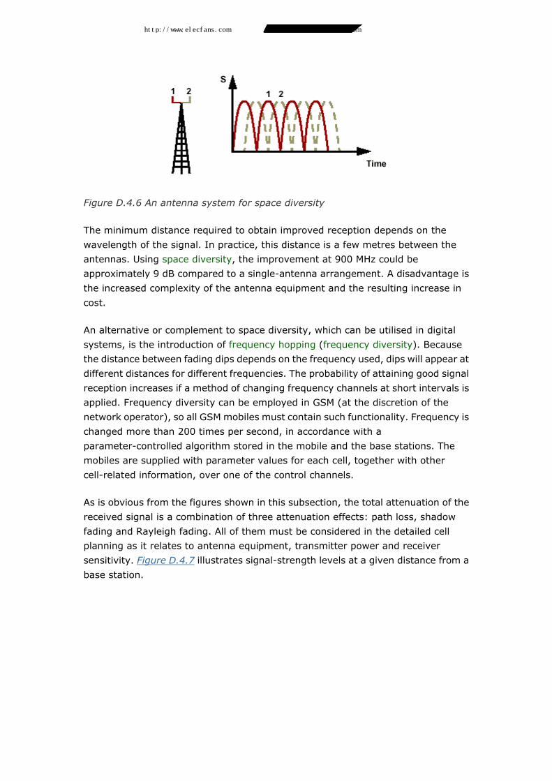
Figure D.4.6 An antenna system for space diversity
The minimum distance required to obtain improved reception depends on the
wavelength of the signal. In practice, this distance is a few metres between the
antennas. Using space diversity, the improvement at 900 MHz could be
approximately 9 dB compared to a single-antenna arrangement. A disadvantage is
the increased complexity of the antenna equipment and the resulting increase in
cost.
An alternative or complement to space diversity, which can be utilised in digital
systems, is the introduction of frequency hopping (frequency diversity). Because
the distance between fading dips depends on the frequency used, dips will appear at
different distances for different frequencies. The probability of attaining good signal
reception increases if a method of changing frequency channels at short intervals is
applied. Frequency diversity can be employed in GSM (at the discretion of the
network operator), so all GSM mobiles must contain such functionality. Frequency is
changed more than 200 times per second, in accordance with a
parameter-controlled algorithm stored in the mobile and the base stations. The
mobiles are supplied with parameter values for each cell, together with other
cell-related information, over one of the control channels.
As is obvious from the figures shown in this subsection, the total attenuation of the
received signal is a combination of three attenuation effects: path loss, shadow
fading and Rayleigh fading. All of them must be considered in the detailed cell
planning as it relates to antenna equipment, transmitter power and receiver
sensitivity. Figure D.4.7 illustrates signal-strength levels at a given distance from a
base station.
http://www.elecfans.com 电子发烧友 http://bbs.elecfans.com 电子技术论坛
Page 37
Figure D.4.7 Received signal strength, distance in metres
It is evident from Figure D.4.7 that cell planning cannot be based only on path loss
and shadow fading. One must also consider Rayleigh fading to attain a sufficient
fading margin. To achieve error-free communications, the global average value
must be as many decibels above receiver sensitivity as the strongest expected
fading dip.
Time dispersion
Another problem caused by reflections is time dispersion.
Figure D.4.8 illustrates the transmission and reception of a bit sequence (here, a
one followed by two zeros). The mobile will receive two signals; one of them is a
reflection that occurred a few kilometres from the mobile. The bit rate of GSM
frequency channels is 270 kbit/s, which is equivalent to 3.7 microseconds per bit -
a time during which the signal travels 1.1 kilometres. If the difference in distance
between the two signals is close on 2 kilometres, the mobile will detect a 0 from the
direct signal (the third bit) and a 1 from the reflected signal (the first bit). This
phenomenon is referred to as inter-symbol interference. If the reflected signal is of
sufficiently high power, such interference will cause the mobile difficulties in
determining whether it received a 1 or a 0.
While Rayleigh fading is caused by small differences in distance between signals
(decimetres or metres), time dispersion is caused by differences on the order of
kilometres. Note also that time dispersion is a phenomenon that only arises in
digital networks.
http://www.elecfans.com 电子发烧友 http://bbs.elecfans.com 电子技术论坛
Page 38
Figure D.4.8 Time dispersion
To neutralise the effects of time dispersion, a technique called equalising is used.
This technique is described in Subsection 4.3.4.
Time alignment
If mobiles in a digital mobile network share a common frequency channel, they must
all send in their assigned time slots so as to avoid overlapping bursts. The instant at
which a mobile is allowed to send will also depend on its distance from the base
station. Both the network and the mobile must therefore include functionality that
continuously regulates the sending instant (time alignment).
Figure D.4.9 Time alignment
Figure D.4.9 illustrates two mobiles which are located at approximately the same
distance from a base station and which have been assigned time slots 3 and 4. This
means that the interval between the instants at which they send is approximately
600 microseconds (the length of one time slot). As mobile M2 moves away from the
http://www.elecfans.com 电子发烧友 http://bbs.elecfans.com 电子技术论坛
Page 39
base station, the time slot it uses (time slot 4) will be received by the base station
later and later. There is then a risk that time slots 4 and 5 will start overlapping one
another (see the bottom illustration in Figure D.4.9 ). Thus, the mobiles' sending
instants must be adjusted at regular intervals, which is controlled via signals from
the base station.
To avoid a need for frequent adjustment, GSM has been designed to include extra
space equivalent to just over an eight-bit sequence (30 microseconds) in its time
slots. This space is used by the base station to balance time delays between
different mobiles. Repeated adjustment is needed only when the signal delay from
a given mobile is close to 30 microseconds (approximately 8 kilometres difference in
distance) in relation to the last adjustment.
The base stations of a D-AMPS network can continuously order adjustment of the
sending instants up to a distance of 92 kilometres.
See also Subsection 4.3.4, which deals with burst formats in GSM.
Transmission technique for the radio path
Digital and analog mobile networks both require the following:
• suitable antennas;
• a modulation method;
• frequency and channel multiplexing; and
• some sort of error handling (both digital and analog mobile networks employ
error-correction techniques for signalling and control information; digital
systems also include functions for error correction on traffic channels).
Additional requirements applicable to digital mobile networks:
• the need for voice coding (see also Chapter 2, Section 2.2) and
• encryption across the air interface.
The "layered" model shown in Figure D.4.10 schematically illustrates the functions
included to support the above requirements. The model is best suited to digital
mobile networks.
The following description focuses on transmission technique for the radio path in
GSM. A short introduction is provided to facilitate understanding of the functions
across the air interface as shown in Figure D.4.10.
Voice is analysed in blocks 20 milliseconds long; in other words, 50 times per
second.
http://www.elecfans.com 电子发烧友 http://bbs.elecfans.com 电子技术论坛
Page 40
Including protection bits, voice blocks are represented by a total of 456 bits
arranged into eight "payload bit sequences" of 57 bits each.
Figure D.4.10 Functions across the air interface
Mobiles send in bursts every fifth millisecond. Between the bursts sent by one
mobile, seven other mobiles (at peak load) send over the same frequency
employing time-division multiplexing (TDM).
Each burst contains 25% of the number of bits representing a block, that is, 114
"payload bits". The length of a burst corresponds to a time slot.
With TDM, eight time slots in a frame are carried by a single frequency channel. At
any particular instant, several mobiles use the same time slot but on different
frequency channels. On one of the frequency channels, two time slots in each cell
are reserved for signalling. The technique for allocating a time slot to a call is called
time division multiple access (TDMA), illustrated in Figure D.4.11.
Figure D.4.11 Time division multiplexing of channels in GSM
D.4.3.1 Voice coding and signalling
In accordance with the structure of our books, we have addressed voice coding in
Chapter 2, Section 2.2. What is most interesting when we study it from the
http://www.elecfans.com 电子发烧友 http://bbs.elecfans.com 电子技术论坛
Page 41
transmission aspect is the resultant 13 kbit/s bit stream from the voice coder -
corresponding to 260 bits per 20 ms block. This user information is carried by traffic
channels.
Air interface signalling is carried by nine types of control channel, described in
greater detail in Chapter 7.
Signalling normally accounts for only a small portion of the total transmission
capacity of the air interface.
D.4.3.2 Error handling
The dependability of the radio medium - with regard to radio interference - cannot
compare with the dependability of a cable. The radio medium contains no insulation
capable of shielding "the line". Consequently, some sort of error handling is required
to attain a transmission quality comparable with that of the fixed network.
Error handling in a mobile network includes both traffic and control channels and is
usually divided into error detection and error correction. Errors are detected by
redundant bits - parity bits, checksums or both - added to the information to be
transmitted across the air interface. Errors are corrected either through
retransmission or through the use of some type of error correcting code (the latter
requires redundant bits over and above those used for error detection). For obvious
reasons, it is not suitable to retransmit information over channels that are used for
telephony (the delays caused by voice coding are enough of a problem to deal with),
whereas retransmission in signalling is fully acceptable. Hence, different error
handling methods are used for traffic channels and control channels.
Control-channel error handling
Relatively advanced error handling methods are applied in mobile networks that use
digital control channels (time slots for signalling). In GSM, a slimmed-down version
of link access procedure on the D-channel (LAPD) is used across the air interface.
This link protocol is referred to as LAPDm. The protocol employs a mode of error
detection based on the use of checksums. Errors are corrected in two different ways:
either through retransmission or by simply discarding faulty signalling messages.
AMPS uses a simpler error handling technique. Twelve parity bits for error detection
are added to the end of each message, and messages found to be faulty are
discarded. This technique assumes that message reception is acknowledged within
a specified time so that incorrectly received messages can be retransmitted.
Digital traffic-channel error handling
http://www.elecfans.com 电子发烧友 http://bbs.elecfans.com 电子技术论坛
Page 42
The following example is based on the error handling method used by GSM for
information transferred on traffic channels. The process includes two phases. In the
first phase - called channel coding - redundant bits are added to the information. In
the second phase, the bits are distributed over a number of bursts in accordance
with a predetermined pattern (interleaving).
Figure D.4.12 Error handling on GSM traffic channels
The majority of the bits delivered by the voice coder to the channel coder are first
block-coded, which means that parity bits are added for error detection. Additional
bits are then added (convolution coding) for error correction. The original 260-bit
sample has now almost doubled in size (456 bits).
The use of channel coding makes it possible to detect and correct single-bit errors,
but one cannot guard against disturbances involving bursts of erroneous bits - a
situation that frequently occurs. Interleaving is a technique that may be able to
solve this problem. The interleaving process is performed in two stages and does
not add any bits. The first stage involves breaking up the 456 bits into groups of 57
bits, as illustrated in Figure D.4.12. A burst can only carry two such groups (as
described in Subsection 4.3.4), so that if portions of a burst are lost, only stray-bit
losses will occur and these losses will be evenly distributed over the voice block. The
lost bits can ordinarily be recovered through channel coding.
If a complete burst is lost, 25% of the total number of bits will be missing, and such
situations cannot be corrected through channel coding. To guard against this
happening, the second stage produces bursts that are a mixture of 57-bit groups
belonging to consecutive voice blocks. The maximum loss will then be reduced to
12.5% of the total number of bits, which can be corrected by channel coding.
However, this technique increases the delay.
http://www.elecfans.com 电子发烧友 http://bbs.elecfans.com 电子技术论坛
Page 43
D.4.3.3 Encryption
Encryption, which is dealt with in Chapter 6 (Subsection 6.2.4). does not contribute
any additional bits.
D.4.3.4 Burst management
Figure D.4.13 An example of a GSM burst format (normal burst)
The principal purpose of burst management is to minimise the effects of bit error
bursts. GSM uses four different burst formats, depending on the type of logical
channel. Figure D.4.13 shows the format used for the majority of logical channels
(normal burst).
Every burst of this sort is capable of carrying 2•57 = 114 encrypted payload bits. 26
known bits, located between the two blocks of payload bits, are used to cope with
any time dispersion and the resultant inter-symbol interference that can have arisen
(see Subsection 4.2.2). By comparing the known bits with the received signal
sequence, it is possible to draw conclusions about the time dispersion. In GSM, this
applies to differences of up to five kilometres between the path travelled by the
direct signal and that travelled by the reflected one. The known bit pattern, along
with a method referred to as equalising, is used to calculate what was actually
transmitted. The tail bits (T-bits) mark the beginning and end of a burst.
The burst format also takes into account the need for time alignment (described in
Subsection 4.2.2). A buffer space 8.25 bits in length (approximately 30
microseconds) is allocated at the end of the bursts, corresponding to about eight
kilometres' difference in distance. Thanks to this buffer, there is no longer any need
for mobiles to constantly adjust their relative sending instants when approaching or
moving away from base stations.
In special cases - primarily for handover control - it may be necessary to utilise
individual bursts for signalling rather than for voice. In such situations, the "stealing
http://www.elecfans.com 电子发烧友 http://bbs.elecfans.com 电子技术论坛
Page 44
flags" (S-bits) are changed to indicate this "theft". See also Chapter 7, Subsection
7.3.3, where the subject of fast associated control channel (FACCH) is addressed.
D.4.3.5 Channel multiplexing: Physical channels in TDMA
The purpose of this section is to describe the GSM subprocess which follows burst
management and which results in traffic from the bursts being loaded onto physical
channels. We also describe the corresponding system techniques in D-AMPS. The
subprocess described in this section is based on TDMA.
Figure D.4.14 Channel multiplexing
As mentioned in the introduction to Section 4.3, a GSM mobile sends in bursts every
fifth millisecond. Every burst contains 25% of the number of bits representing a
voice block. The length of a burst corresponds to one time slot which can be
regarded as a physical channel in the air interface. We usually differentiate between
logical channels, which indicate how a channel is used, and physical channels, which
represent a transmission resource.
A physical channel - for example, a time slot on a particular frequency channel in a
TDMA system - may be said to be a carrier of a logical channel, such as a traffic
channel (sometimes abbreviated TCH), or several logical channels, such as various
control channels in a multiframe structure. The latter case is discussed in Chapter 7,
Subsection 7.3.4.
In digital systems based on TDMA, such as GSM and D-AMPS, the mapping process
means that a time slot and a frequency are allocated to the traffic burst. If frequency
hopping is applied, the frequency of a traffic channel also changes - in GSM slightly
more than 200 times a second (see Subsection 4.2.2).
The frequency channel separation in GSM is 200 kHz; in D-AMPS 30 kHz. In GSM,
each cell is provided with a frequency channel (C0) for control channels. Normally,
time slots 0 and 1 (TS0 and TS1) on C0 are used for this purpose. The remaining six
http://www.elecfans.com 电子发烧友 http://bbs.elecfans.com 电子技术论坛
Page 45
time slots on C0 and all eight time slots on other frequencies are used for traffic
channels. See Figure D.4.15. In D-AMPS, each frequency channel is normally used
for three traffic channels.
The traffic channels convey voice or data (such as Internet traffic) between the
mobile and base station. The channels are allocated on a per call basis. Ordinarily,
a time slot is used for one call only (full rate), but an alternative with two calls per
time slot (half rate) has also been specified.
The physical channel in GSM - that is, the time slot - has a length of 0.577
milliseconds. This length is sufficient for one traffic channel burst plus a guard
period. For the frequency channels between the mobile and base station (uplink),
the frequency range 890-915 MHz is used, while the downlink utilises the range
935-960 MHz.
The total number of duplex frequency channels is 124, resulting in 992 physical
channels (compared to 823 in AMPS and D-AMPS).
In contrast to AMPS, GSM does not dictate how the 124 frequency channels may be
used. However, each GSM cell must have a C0 frequency.
All modern mobile systems are based on multiple access, which means that all users
have simultaneous access to the medium. This requires a number of rules to
prevent situations in which mobiles "all talk at the same time". The medium, which
is a common resource, must satisfy the needs of all users.
Figure D.4.15 The principle of time division multiple access
Traffic channels are assigned through control-channel signalling.
Each cell in a cellular system can be regarded as an individual medium because a
mobile leaving the cell loses contact with that cell's base station. However, all
mobiles in the cell utilise the same radio resource, namely, that portion of the
frequency spectrum which has been assigned to the cell. The following describes
two other techniques applicable to channel multiplexing using multiple access:
FDMA and CDMA.
http://www.elecfans.com 电子发烧友 http://bbs.elecfans.com 电子技术论坛
Page 46
D.4.3.6 Alternative 1: Physical channels in FDMA-based systems
Frequency division multiple access (FDMA) is the technique used by analog mobile
telephone systems, such as NMT and AMPS. The access principle is illustrated in
Figure D.4.16.
The frequency range assigned to the cell consists of one uplink (mobile to base
station) and one downlink (base station to mobile). The frequency separation
between these links must be sufficiently large - normally 45 MHz (duplex separation)
- so that no interference between them will arise at the mobile.
Each link is divided into an equal number of unidirectional channels. One channel
should be sufficiently wide (25-30 kHz) to be able to transmit telephone-quality
voice (approximately 3 kHz). To be able to make use of duplex telephony, the
mobile must have access to one uplink and one downlink channel - two channels
combined to form a traffic channel pair.
Figure D.4.16 The frequency division multiple access principle
However, a cell consists not only of traffic channels; each cell contains a number of
channels that are predefined as control channels. Such channels can use the
downlink for the distribution of cell and network information and to transfer call
requests arriving from the network and use the uplink frequency for call signalling
generated by mobiles. One or more other channels may have been defined as
control channels for two-way signalling between the mobile and the network.
The total number of FDMA system channels is standardised and is specified by the
government agency that allocates frequencies. The uplink frequency range of the
AMPS system is 824-849 MHz and its downlink range is 869-894 MHz. Every link
contains a total of 823 unidirectional channels. Only half of the channels are
available to any given operator, since the standard stipulates that there is to be
room for two competing AMPS operators in every geographical area. AMPS also
stipulates which channels are to be used as control channels and which will be used
for traffic.
http://www.elecfans.com 电子发烧友 http://bbs.elecfans.com 电子技术论坛
Page 47
A comparison between TDMA and FDMA
The primary advantages of TDMA over FDMA are its greater capacity and the fact
that TDMA is less sensitive to noise, so mobiles can operate with lower power.
Another advantage is that the mobile can use a number of time slots freely (since it
can only send in its own time slot). For example, the mobile may perform alternative
frequency signal measurements - a prerequisite for mobile-assisted handover
(MAHO), as in GSM, or mobile-controlled handover (MCHO) as in DECT.
D.4.3.7 Alternative 2: Physical channels in CDMA-based systems
Code division multiple access (CDMA) is no new technique. It has been utilised in
military systems and for satellite communications for many years, but it has also
started to be used in mobile network applications.
CDMA systems are not divided into frequencies, nor are they divided into time slots.
All mobiles are capable of transmitting and receiving over the entire frequency band.
Instead, a "third dimension" is used to separate traffic channels, namely coding.
Figure D.4.17 The code division multiple access principle
A typical feature of the CDMA technique is that all mobiles in the network are
assigned a unique code: a chip sequence. When a mobile wishes to transmit a bit
stream, it replaces every bit with its code (for ones) or with the code's ones
complement (for zeros). Figure D.4.18 illustrates the simultaneous transmission of
two bits from each of two mobiles which have different chip sequences. We assume
in this example that the network uses eight-bit chip sequences; in reality, they are
much longer.
The result is that eight bits (referred to as a "chip") are transmitted for every bit.
Provided that the same modulation methods are used as those used in TDMA, the
required bandwidth will be correspondingly larger. Instead of using some tens of
kHz for a voice channel, the chip will be modulated over approximately 1 MHz. That
is why this technique is also referred to as a spread-spectrum technique.
The two mobiles in Figure D.4.18 transmit at the same time and use the same
frequency band. Consequently, the chip streams will be interleaved in the base
http://www.elecfans.com 电子发烧友 http://bbs.elecfans.com 电子技术论坛
Page 48
station. How then can the base station detect and separate the two bit streams: 01
and 11? The mathematical method is somewhat complicated. It is based partly on
the fact that each mobile has a unique chip sequence, which is also known to the
base station, and partly on the fact that all chip sequences are orthogonally paired.
This means that if any two chip sequences are multiplied, the product is always zero.
Only when a chip sequence is multiplied by itself will the product be a 1. When the
receiver is to extract the chip stream for mobile A, it multiplies this mobile's chip
sequence by the received, interleaved chip stream. Thus, all chip streams except
those pertaining to mobile A are eliminated. It is then a simple matter to reduce the
chip stream to A's bit stream by applying A's chip sequence.
Figure D.4.18 Two mobiles simultaneously transmitting two bits each
D.4.3.8 Modulation
Modulation, transmission and reception are performed at the bottom of the
functional hierarchy, as shown in Figure D.4.10. All channels to the transmitting
antenna and from the receiving antenna are multiplexed and demultiplexed,
respectively, in the base station. Every duplex channel is handled by a separate -
transceiver (TRX). The mobile contains a controllable oscillator for channel selection
and a duplex filter that separates the send and receive frequencies.
Base station transmission power is 1-50 W, depending on the type of system and
the desired cell size: a macrocell, a microcell or a picocell. Mobile output power is
0.6-20 W, depending on the type of mobile (hand-held or car-mounted). Mobiles
must be capable of adjusting their output power in steps if ordered to do so by the
base station (power regulation).
Receiver sensitivity is expressed in dBm.
The modulation methods described in Volume 1, Chapter 4, Subsection 4.4.2, are
also used in mobile networks. Analog systems employ frequency modulation
whereas, as a rule, phase shift modulation is applied in digital systems.
http://www.elecfans.com 电子发烧友 http://bbs.elecfans.com 电子技术论坛
Page 49
D.4.3.9 Antennas
Mobiles are equipped with omnidirectional antennas of the quarter-wave type
adapted to the frequency band used (450, 800, 900, 1800 or 1900 MHz). The mobile
uses the same antenna for transmission and reception. The antenna must have
broadband characteristics, that is, similar radiation characteristics over the entire
frequency range in question (for GSM, 70 MHz between the lowest and highest
frequencies).
A cell's geographical coverage determines the type of antenna that the base
stations are to be equipped with. Omnidirectional antennas are used for
omnidirectional cells, and directional antennas - with or without space diversity -
are used by sector cells. Different antennas are sometimes used for transmission
(high-power) and for reception (low-power) but are usually mounted on the same
mast. If the same antenna is used for transmission and reception, it must be fitted
with a duplex filter.
The ideal antenna radiates all its power in the horizontal plane; if it were
omnidirectional it would do so equally well in all directions. But in reality no antenna
is perfect, because the mast, the proximity to the earth and conductive objects
affect the radiation pattern.
Figure D.4.19 A base station's actual radiation pattern
Figure D.4.19 illustrates the radiation pattern in the horizontal plane. The inner grey
area shows the measured radiation for an omnidirectional antenna mounted a bit up
the mast. Note especially the lobed form and the screening effect of the mast on
radiation. The outer area (dark grey) represents the radiation of another
omnidirectional antenna that is equipped with a quarter-wave reflector, intended to
decrease the lobe formation.
The choice of antenna type, antenna placement on the mast and the resulting
radiation pattern are important factors that operators must consider in their cell
planning.
http://www.elecfans.com 电子发烧友 http://bbs.elecfans.com 电子技术论坛
Page 50
1. trunk and access networks Introduction
In Chapter 4 we stated that the main difference between transmission in a mobile
network and transmission in a fixed network lies in the methods of access. Key
differentiating factors are the PLMN's multiple access and the way in which contact
is maintained between mobiles and the network. In this chapter, we will discuss the
access network seen as an infrastructure for the transport of user information and
signalling. (See Figure D.5.1.) Other functions needed in mobile telephony
(registration, set-up, authentication, and so forth) require considerably more
network intelligence and are therefore discussed in Chapter 6.
The trunk network is viewed as the transport section of the core network. Since it is
technically similar to the trunk part of other networks (such as the PSTN and ISDN),
it will not be treated here.
The access network's resources in the form of traffic channels are shown in Figure
D.5.2.
Figure D.5.1 and Figure D.5.2,together with Figure D.7.1 in Chapter 7, illustrate two
aspects of the access network:
• A rough, geographical division of the PLMN into an access network and a core
network. Here, all MSC functions belong to the core network, while the BSC
is part of the access network.
• A more detailed, function-dependent division (see the introduction to this
chapter) where the access network is regarded as a resource for transporting
user information and signalling between mobiles and the MSC.
The latter alternative is used only when the functionality of the access network must
be divided into layers. This applies to Chapter 7 in particular, but also to the
description given in this chapter.
http://www.elecfans.com 电子发烧友 http://bbs.elecfans.com 电子技术论坛
Page 51
Figure D.5.1 GSM access network
Figure D.5.2 Access network resources for traffic channels in GSM
The access network consists of two main parts: the air interface and the fixed part.
Time slots TS2-TS7 on frequency channel C0 plus all eight time slots on the other
available frequencies are used as traffic channels across the air interface of a cell.
Those PCM time slots which are not dedicated for synchronisation and signalling are
used between the base station and the BSC, and between the BSC and the MSC.
Logical traffic channels are available at two levels: 13 kbit/s full-rate channels (at
the top level), which interconnect the voice coders of the mobile and the MSC, and
64 kbit/s channels between the BSC and the MSC.
http://www.elecfans.com 电子发烧友 http://bbs.elecfans.com 电子技术论坛
Page 52
If the network offers half-rate coding as well, the model will include 6.5 kbit/s
channels and coders in addition to the 13 kbit/s channels and coders. Pooling the
voice coders in the BSC makes it easier (and cheaper) to offer different types of
voice channel than it would be if they were installed in the base station.
To obtain channels having a useful bandwidth of 13 kbit/s and acceptable quality
across the air interface we need functions for error handling, encryption/decryption,
burst management, and the like. (See Chapter 4, Section 4.3.) A 33.8 kbit/s traffic
channel across the air interface is used to accommodate these functions, together
with the useful bandwidth. A 64 kbit/s channel is used for transporting four full-rate
traffic channels between the base station and the BSC. This section requires no
special protection bits.
Access network signalling is dealt with in Chapter 7.
The air interface
The air interface is the shared boundary between a mobile and the base station.
Physically, it is delimited by the cell structure. The characteristics of individual cells
are determined by the structure of the base stations and by the resources allocated
to these stations.
D.5.2.1 Cell pattern
The features of a cell are determined by two basic factors: its geographical reach (in
practice, its coverage) and the frequencies that have been allocated to it. The
geographical reach of a cell is dimensioned by the choice of type of antenna, the
position of the antenna, and its output power. Theoretically, a cell can be described
as a hexagon, but its actual geographical coverage must be determined through
different types of measurement.
Each cell is allocated a number of frequencies for control and traffic channels. The
number of traffic channels is determined by the expected traffic intensity and the
congestion threshold, that is, the GoS. Traffic intensity (measured in Erlangs) is
calculated as the average number of simultaneous calls per unit of time. Using
Erlang's first formula, we can calculate the number of channels that the cell will
need for a given probability of congestion.
Let us look at a simple case. If the average number of mobiles in the cell is 80 and
each mobile is assumed to generate a traffic flow of 0.025 Erlang (corresponding to
a 90-second call every three hours), and if we accept a probability of congestion of
2%, then the cell will need six traffic channels.
If the system is of the AMPS type, we will need six frequency channels for traffic - in
addition to the control channels. If the system is of the GSM type, only one
http://www.elecfans.com 电子发烧友 http://bbs.elecfans.com 电子技术论坛
Page 53
frequency channel (the one for frequency C0) will be needed. Time slots 0 and 1 on
C0 are available for use as traffic channels.
To cover a large area that is visited by many mobiles, we need a large number of
cells, and the available frequencies will also have to be reused. Since two adjacent
cells cannot use the same frequencies because of the risk of interference, we must
set a minimum reuse distance to prevent a given frequency in one of the cells from
interfering with the same frequency in another cell (co-channel interference). We
must also take a closely related phenomenon into account: adjacent channel
interference (C/A).
The reuse distance for frequencies is defined as the relationship between the
desired signal strength (in the cell) and an undesired signal strength (in the nearest
cell allowed to use the same frequency). This relationship is called
carrier-to-interference ratio (C/I).
Figure D.5.3 Co-channel interference
In Figure D.5.3, cell A and cell B use the same frequency f1. This is acceptable as
long as the C/I between the signal strength from B (S(B,f1) = the signal strength in
B of the frequency f1) and the signal strength from A - that is, S(A,f1) - recorded in
all parts of cell B, exceeds the minimum value that the system can accept. See
Figure D.5.4. Minimum values are 18 dB in analog and 7 dB in digital systems.
Figure D.5.4 Reuse distance and carrier-to-interference ratio
http://www.elecfans.com 电子发烧友 http://bbs.elecfans.com 电子技术论坛
Page 54
A similar definition applies to interference between adjacent channels. In GSM, the
term "adjacent channel" denotes a frequency that is 200 kHz from the desired
frequency. In AMPS, the corresponding figure is 30 kHz.
By arranging the cells in clusters we can easily ensure a sufficient reuse distance
between two cells that use the same frequencies, see Figure D.5.5.
Figure D.5.5 A "7/21" cell pattern for reuse of frequencies
Figure D.5.5 illustrates a 7/21 cell pattern, a common method for reusing
frequencies. In 7/21, the available number of frequencies is divided into seven
groups, A to G. A group consists of three cells, and the frequencies are distributed
among the three cells of each group. The seven groups can be arranged in a cluster
consisting of 21 cells. A larger network is then created by adding more clusters (in
the figure there are three clusters). The cells are dimensioned so that the distance
between a group in a cluster and the corresponding group in the neighbouring
cluster meets the requirement for C/I.
However, the traffic intensity in the geographical area covered by the cell is not
homogeneous. The fact that it increases with time must be taken into account in the
original cell planning. Many methods have been designed to adapt cell planning to
the actual traffic situation:
• The number of frequencies in cells with large traffic volume can be increased.
The requirement for reuse distance is a limiting factor, though.
• The reuse of frequencies can be increased through the introduction of
smaller cells in areas where traffic intensity is high (cell split).
http://www.elecfans.com 电子发烧友 http://bbs.elecfans.com 电子技术论坛
Page 55
Figure D.5.6 Cell split
• In networks with analog air interface, we can increase capacity by
introducing digital cells. This solution is attractive on condition that the
mobiles can use both analog and digital traffic channels (dual mode).
• A network consisting of 800 MHz or 900 MHz cells can be extended to include
1800 MHz or 1900 MHz cells as well. A transition from GSM 900 to GSM 1800
means an additional 2,992 traffic channels. The mobiles should be able to
operate on both 800/900 MHz and 1800/1900 MHz (dual band).
• Hierarchical cell patterns can be introduced. Fast-moving mobile units can be
referred to large cells to reduce the network load caused by handover and
registration. (See also Chapter 10, Subsection 10.4.4.)
D.5.2.2 Channel allocation
Channels can be allocated according to two different principles: fixed and dynamic
allocation.
Fixed allocation is the traditional method. This means that the frequency spectrum
is divided into a number of groups corresponding to the number of cells in a cluster.
The cells in the core of a city and other areas with high traffic density are small,
while larger cells are used to cover backstreets with relatively sparse traffic.
However, forecasting traffic intensity with sufficient accuracy is no easy task. We
will either have to make extensive measurements or allow wide margins.
Dynamic channel allocation means that the cell is given access to a channel only
when the need arises. This method takes interference into account: The cell is
allocated a channel that will neither disturb nor be disturbed by adjacent cells. But
then, all cells must be capable of handling all channels of the frequency spectrum,
which requires more advanced antenna equipment and, hence, results in higher
costs.
We also distinguish between two types of dynamic allocation of channels, as
described below.
Channel allocation based on traffic demand
The planned reuse distance is maintained (which means limited flexibility), but the
channels can be reallocated to suit the current traffic demand.
Channel allocation based on traffic demand and interference
The main difference between this method and the previous one is the introduction of
the interference factor, making the reuse distance less important. When the
channels are reallocated, the interference level is assessed by estimating the
http://www.elecfans.com 电子发烧友 http://bbs.elecfans.com 电子技术论坛
Page 56
resultant bit error ratio. In this way, a channel can be used in any of the cells,
provided it does not cause interference.
The latter method means considerably less planning work, which is of great
significance in the case of microcells and picocells. Besides, there will be a certain
increase in capacity because the margins set when planning fixed reuse distances
are usually quite generous.
The fixed part of the access network
D.5.3.1 Base transceiver stations and base station controllers
A base station handles the air interface for one or more cells, its primary task being
to relay traffic between mobiles and the rest of the network (BSCs and MSCs). A
base station also provides the infrastructure for the resources allocated to one or
more cells.
In Figure D.5.7 ,which gives a basic overview of a GSM access network, all base
stations except BTS112 serve a single cell, while BTS112 serves three cells. All base
stations are physically connected to a drop-and-insert transmission system (the
model on the left), but in logical terms each cell must have its own channels in this
transmission system (the model on the right).
Figure D.5.7 Physical and logical structures in the access network
The dimensioning of the access network between the BTS and the BSC is based on
the number of channels required by each cell. To be able to determine this figure,
we must be somewhat familiar with the design of a base station. (See Figure D.5.8.)
http://www.elecfans.com 电子发烧友 http://bbs.elecfans.com 电子技术论坛
Page 57
Figure D.5.8 A base station in GSM
The base station in Figure D.5.8 handles three cells: A, B and C. Each cell has a
separate antenna, but all three antennas are mounted on the same mast. Each cell
is allocated a number of channel units, or transceivers (TRX), one for each
frequency channel used in the cell. The group of TRXs that belongs to a cell is called
a transceiver subsystem (TRS).
Traffic to and from base stations is coordinated by a unit called the transceiver radio
interface (TRI). The TRI contains a selector since its primary functions are to
distribute channels between the BSC and the appropriate channel unit and to relay
channels between the BSC and neighbouring base stations. The TRI can also
communicate with the BSC over a separate 64 kbit/s channel on the PCM link. This
channel can be used by the TRI and its BSC to transfer control channel information
and to communicate in matters related to operation and maintenance in the base
station. The BSC uses the same channel for a number of tasks, such as adjusting the
frequency and power of the channel units (TRXs); determining in which cells these
units should be employed; disconnecting defective channel units; and receiving
alarms.
PCM links are used to interconnect base stations and to connect them to the BSC. A
TRX in GSM is used for six or eight 13 kbit/s traffic channels, depending on whether
the cell's C0 channel or some other frequency channel is used. A 64 kbit/s PCM
channel can transport four such traffic channels to and from the BSC. As we just said,
each TRI (hence, each base station) requires a separate 64 kbit/s channel. We can
use this information, and the number of frequencies allocated to each cell, to
dimension the transmission network between the BSC and its base stations. Figure
D.5.9 exemplifies drop-and-insert transmission between the BSC and three base
stations.
http://www.elecfans.com 电子发烧友 http://bbs.elecfans.com 电子技术论坛
Page 58
Figure D.5.9 Dimensioning access using drop-and-insert transmission in GSM
In the example, only one frequency is used in the BTS114 cell, which means six
traffic channels. This requires two PCM time slots plus one PCM time slot for the TRI
in BTS114. In other words, BTS114 will have access to three PCM time slots on the
link to BTS115. The link between BTS115 and BTS116 will carry time slots to both
BTS114 and BTS115. Between BTS116 and the BSC we need three time slots for
traffic between the TRI and the BSC, or a total of 12 time slots for the 42 traffic
channels. This means that a single PCM link will suffice in our example. There are
plenty of free time slots on the PCM links, plus spare space in the PCM time slots
used, unless all traffic channels on the available frequencies are occupied.
D.5.3.2 Base station controllers and mobile switching centres
The purpose of the BSC concept in GSM is to relieve the MSC of the handling of
functions and resources that relate to the radio medium and to terminal mobility. All
traffic channels in the interface to the MSC are 64 kbit/s channels and use SS7 for
signalling. Under these circumstances, the MSC will have the same basic structure
as an exchange in the PSTN.
When dimensioning the access network in GSM, the operator must determine how
each BSC should be deployed in relation to its MSC. An important consideration in
this deployment is the fact that a BSC will be most cost-effective if it can serve a
whole MSC service area.
http://www.elecfans.com 电子发烧友 http://bbs.elecfans.com 电子技术论坛
Page 59
Figure D.5.10 Deployment of BSCs
A BSC can either be located on the same site as the MSC or it can be a stand-alone
unit deployed as close as possible to the base stations it serves. For several reasons,
co-location can be the most economical solution, but transmission costs must also
be taken into account. Figure D.5.10 shows a possible scenario.
The illustration to the left shows a network section in which the traffic volume is
moderate but expected to increase. Consequently, a BSC has been located centrally
in the area. When the number of subscribers increases to a level that justifies the
use of a separate MSC, this node can be installed at a relatively low cost in the same
building as the BSC (as shown on the right).
Handover
D.5.4.1 Introduction
Reswitching due to handover is described in Chapter 3, Section 3.3. We will now
describe the process leading up to handover.
Since a mobile often moves while communicating, the signal via radio access can
deteriorate, especially near cell boundaries. To cope with this problem, the system
must check whether a free traffic channel in a neighbouring cell would improve
signal quality, and - if this is the case - switch the call to that channel. This process
includes three phases:
• continuous recording of signal strength and signal-to-noise ratio between
mobile and base station;
• analysis resulting in the selection of a suitable cell and radio channel; and
http://www.elecfans.com 电子发烧友 http://bbs.elecfans.com 电子技术论坛
Page 60
• switch-over to the new cell and radio channel.
Locating is the collective term for the first two phases.
D.5.4.2 Locating
Quality supervision
In digital systems, the signal quality is supervised through separate measurements
on every traffic channel. For a change, we will now exemplify the locating function
by means of an application in analog systems. In this application, every frequency
is supervised by a special tone, called the supervisory audio tone (SAT), which is
applied to the traffic channel. The tone is above the upper limit of the speech band
and cannot be perceived by the users.
The base station sends the SAT with voice to the mobile, which receives the tone
and returns it to the base station, where signal strength and signal-to-noise ratio
are measured. However, there is a certain risk of the process going adrift. A channel
in a base station can receive an SAT not only from a mobile in its own cell but also
from a mobile in another cell that uses the same frequency. If so, the base station
might check the wrong channel and obtain a misleading indication. To avoid this,
several SAT frequencies (mostly 5970, 6000 and 6030 Hz) are used. Cells using the
same channels where interference problems are liable to occur have different SATs.
Two alarm levels are used when measuring signal-to-noise ratio:
• signal-to-noise ratio for handover request (SNH) and
• signal-to-noise ratio for release (SNR).
If the result of the measurement is less than the SNH value, handover is requested.
If the handover attempt fails (for example, because of congestion in neighbouring
cells) and the signal-to-noise ratio keeps falling to the SNR value, then the call is
disconnected.
The recorded signal strength is compared with the following levels:
• signal strength decrease (SSD) initiates a request for power reduction;
• signal strength increase (SSI) initiates a request for power increase;
• signal strength handoff (SSH) initiates a request for handover; and
• signal strength blocking (SSB) initiates a request to block a voice channel.
If the measured signal strength exceeds the SSD value, the mobile is ordered to
reduce its output power. (Excessive output power can cause interference in other
cells.) An increase in output power is ordered when the recorded signal strength is
below the SSI value. If the signal strength is decreased further, the network will
http://www.elecfans.com 电子发烧友 http://bbs.elecfans.com 电子技术论坛
Page 61
order the output power to be increased to the maximum value specified for the type
of mobile involved. If the signal strength is not increased, the sound quality will
deteriorate, and when the signal strength has reached the SSH value, the network
will make a handover attempt.
The SSB value is used when measuring idle voice channels. A signal strength value
exceeding SSB is an indication of interference from another cell and will cause
blocking of the channel in question.
Handover methods
Several standardised handover methods are available. (See Figure D.5.11.) In GSM,
the network (that is, the BSC) decides when handover is necessary, whereas in
DECT systems the mobile itself measures signal strength and makes handover
decisions. Of course, delegating the decision-making process to the mobile reduces
network load.
Figure D.5.11 Different handover methods
Network-controlled handover (NCHO) is common in analog systems. The network
measures the transmission quality via the base stations and decides when handover
should be executed. The mobile makes no measurements. This method results in
intense signalling between the base station and the node that decides on handover,
but, on the other hand, signalling on the air interface is minimised because there are
no recorded values to be transferred.
MAHO means that the mobile continuously measures the signal strength from
neighbouring base stations and sends the recorded values to the base station to
which it is currently connected. At the same time, both the mobile and the base
station test the quality of the established connection. On the basis of these test
values, the network decides when handover should take place. An advantage of this
method is the fact that the mobile's situation is taken into account, since the mobile
itself does the measuring. Also, the need for measurements in neighbouring base
stations will decrease drastically. A disadvantage (as compared with the NCHO
method) is considerably increased signalling across the air interface. However,
http://www.elecfans.com 电子发烧友 http://bbs.elecfans.com 电子技术论坛
Page 62
despite this increase, the transfer of recorded values will only represent a few
percent of the total traffic and thus pose no major problem.
MCHO resembles the MAHO method except in one respect: the handover decision
has been delegated to the mobile. The result is a system which reacts quickly to
changes in the radio environment. On the other hand, it can be more difficult to
change the conditions for handover in a decentralised system.
In certain situations, handover cannot be executed. All traffic channels in the new
cell may be busy, especially in those parts of the network where traffic volume is
increasing rapidly. Also, all idle channels can be blocked by radio interference, in
which case the mobile must stay connected to the original channel although the
voice quality decreases. At best, the mobile is approaching a third cell with idle
traffic channels; at worst, the voice quality falls to a level that causes disconnection
of the call.
In countries where different operators compete in the same geographical area, they
sometimes enter into agreements that allow them to use one another's systems.
This means that handover can take place between neighbouring cells that belong to
different mobile networks.
D.5.4.3 Handover - An example
Figure D.5.12 illustrates a complex case of inter-MSC handover in GSM.
The mobile is in cell BTS112 and moving towards cell BTS211. Cell BTS112 is
handled by BSC11 under MSC1, while cell BTS211 is handled by BSC21 under MSC2.
The original connection is assumed to have been established between a subscriber
in the fixed network - via GMSC, MSC1, BSC11 and BTS112 - and the mobile.
The locating function in BSC11 has identified the mobile's need for handover, based
on the quality of its signals reported by BSC11's base stations. The mobile itself has
also reported the quality of signals generated by a number of base stations around
cell BTS112, including base stations in cells handled by other MSCs and BSCs. By
analysing all this data, BSC11 has been able to identify a number of cells (usually
the best six) that provide acceptable signal quality, including BTS211. BSC11 has
also found that it is not responsible for any of the cells.
1. BSC11 informs its MSC that the mobile needs handover. It also indicates the cells
that are suited for handover and gives priority to BTS211.
2. After analysing the situation, MSC1 sends a signal to MSC2, requesting handover
to cell BTS211. MSC1 also sends the mobile's subscriber data which is stored in its
VLR.
http://www.elecfans.com 电子发烧友 http://bbs.elecfans.com 电子技术论坛
Page 63
3. MSC2 orders BSC21 to allocate an idle traffic channel to the mobile.
4. BSC21 allocates an idle channel (provided such a channel is available).
5. MSC2 indicates the channel in BTS211 to which the mobile should be connected.
Then MSC1 and MSC2 reserve new paths for the connection through their switches.
Figure D.5.12 Inter-MSC handover
6. MSC1 orders BSC11 to check that the mobile is connected to the new traffic
channel in BTS211, and BSC11 orders the mobile to change channels.
7. After the mobile has changed channels, it must acknowledge this order. The
acknowledgement is received by BSC21 and sent on to MSC2. If no
acknowledgement appears within a preset time, the connection is cleared.
8. MSC2 now makes a through-connection from MSC1 to BSC21 in its own switch
and sends the acknowledgement on to MSC1. MSC1 sets up the new path between
the GMSC and MSC2 in its switch and disconnects the previous one between the
http://www.elecfans.com 电子发烧友 http://bbs.elecfans.com 电子技术论坛
Page 64
GMSC and BSC11. Then BSC11 is ordered to release the original traffic channel in
BTS112.
The handover process is now finished. If the selected cell does not accept handover,
the next cell on the list will be selected.
1. network intelligence Introduction
Two aspects of network intelligence are addressed in this chapter: the increase in
intelligence required by radio access and terminal mobility functions, and the
significant role that intelligent network services (IN services) play in mobile
networks. Most basic services in mobile systems are more or less identical,
regardless of operator. But by introducing and marketing IN services, an operator
can make his network more attractive than those of his competitors.
In mobile networks recently installed, the trend is towards decentralisation. To
reduce network load and provide space for IN services, operators move the
intelligence that supports terminal mobility and incorporate it in the mobile. This
reduces the need for signalling in the network, because the mobile will be more
autonomous. In the DECT system, for example, the mobile initiates and controls
handover operations.
Some IN services in mobile networks are identical with those available in
PSTN/ISDN, while others are specific to the PLMN. When introducing IN services it is
often advisable to begin by installing an integrated switching and service node
(SSCP). As the demand for these services increases, separate SSP nodes and a
common SCP can be introduced. In a growing network, it can also be advisable to
deploy the SSPs (which are call-switching units) as close to the subscribers as
possible in order to shorten transmission paths. Integration of the SSP and MSC in
one and the same network element can be a viable alternative. Figure D.6.1
illustrates this scenario.
An integrated MSC/SSP must have extremely great processing power, because the
network element must be capable of handling call set-up, registration, paging,
handover and SSP functions. To ensure high availability performance (and satisfied
customers), the operator usually duplicates the network intelligence nodes.
IN is used not only in one or more mobile networks. In combination with universal
personal telecommunication (UPT), for example, IN is also an excellent tool for
integrating different types of bearer network, such as the PSTN, ISDN, PLMN and
satellite-based networks for mobile communications. Number portability is an
important service when mobiles move from one operator to another within the same
type of network or between different networks.
http://www.elecfans.com 电子发烧友 http://bbs.elecfans.com 电子技术论坛
Page 65
Figure D.6.1 Scenario for IN services in the PLMN
Registration and paging
The three concepts registration, paging and location area are explained in Chapter
1, Subsection 1.1.4. An example of how some of these functions and features are
utilised is given below.
Figure D.6.2 exemplifies registration and paging in a GSM mobile network. The
network is logically divided into four location areas, LA1-LA4, each corresponding to
a BSC service area:
1. When the mobile is turned on, it is activated in LA1. (At this stage the network
does not know that the mobile is active.) The mobile locks onto the cell in which it is
currently located and is given the local area identity (LAI) through the cell's control
channel. The LAI consists of three parts - a mobile country code (MCC), a mobile
network code (MNC) and a location area code (LAC) - which together make up the
global identity of the area. Since the mobile is not registered as active in the
network, it must contact the MSC and report its position, that is, LA1. MSC1 enters
the mobile's position in its VLR and then sends a signal to the HLR reporting the
mobile active in its service area. The mobile receives an acknowledgement, which
concludes the registration process.
2. The mobile enters an LA2 cell, reads a new LAI on the control channel and makes
a new registration. This information, too, is received by MSC1, which changes the
LAI in its VLR. Note that the change need not be reported to the HLR, because the
mobile is still in the same MSC service area.
http://www.elecfans.com 电子发烧友 http://bbs.elecfans.com 电子技术论坛
Page 66
Figure D.6.2 Registration and paging
3. The mobile enters an LA3 cell, and now the registration is received by MSC2.
Since the mobile is "new" in MSC2's service area, it is reported to the HLR, which
informs MSC1 that the mobile has entered another MSC service area. Consequently,
MSC1 deletes it from its VLR.
4. This is the paging sequence. Now, assume that the GMSC receives a call
addressed to the mobile after it has been registered in LA3. In answer to a question
to the HLR, the GMSC is informed (indirectly through a routing number) that the
mobile is in MSC2's service area. From its VLR, MSC2 finds out that the mobile was
last registered in LA3. Provided LA3 only consists of cells within BSC21's service
area, MSC2 requests paging from BSC21, which responds by sending a paging call
to all base stations in LA3. If the mobile is still in an LA3 cell, it will answer the call.
The example illustrates the importance of the mobile being able not only to register
when it is turned on and when it enters a new location area, but also to report when
it is turned off. This procedure is called detachment in GSM. Information showing
that the mobile is turned off is stored in the MSC that receives the information and
in the HLR. Thus, if a mobile that is currently off is called from another network, the
call will stop at the GMSC level.
Instead of automatic registration, a manual procedure can be initiated (by means of
a smart card in GSM). The user gains access by inserting the smart card into his
mobile, and registration then proceeds as in step 1 above.
http://www.elecfans.com 电子发烧友 http://bbs.elecfans.com 电子技术论坛
Page 67
Setting up and releasing a mobile call
igure D.6.3 shows how a connection is set up between a telephone in the fixed
network (PSTN) and a mobile in a mobile network.
1. The subscriber in the fixed network dials the B-subscriber's mobile number. The
PSTN identifies the number and sets up a connection to the called network (GMSC).
2. The GMSC does not know through which MSC (or in which interworking mobile
network) the mobile can be reached; nor does it know whether the mobile is free,
busy, turned on or turned off. To be able to continue, the GMSC must therefore
request a routing number from the HLR.
3. The registration function continuously updates the HLR on the location of the
mobile (that is, in which MSC service area it is to be found). Provided the mobile is
turned on and free, the HLR will call that service area's VLR and request a free
routing number. The mobile's subscriber data is sent along with this request.
4. The GMSC receives the routing number and uses it to select a route in the PLMN.
In our example, the GMSC forwards the call to MSC1.
5. MSC1 consults its VLR to find out in which group of cells (location area) the mobile
is at the moment. (Keeping the VLR informed of the mobile's location is also part of
the registration function.) MSC1 then orders BSC11 to find the mobile.
http://www.elecfans.com 电子发烧友 http://bbs.elecfans.com 电子技术论坛
Page 68
Figure D.6.3 Setting up a connection from the PSTN to a mobile
6. BSC11 sends a paging call to all cells in its service area that can be visited by the
mobile at the moment. When the call is answered, BSC11 allocates the mobile a
control channel for signalling with MSC1. A traffic channel over radio access and
between MSC1 and BSC11 is also reserved for the call.
7. Signalling between MSC1 and the mobile concludes with the set-up of a traffic
channel through the switches in BSC11 and MSC1. A connection has now been
established between the telephone in the fixed network and the mobile.
In all essentials, the procedure for clearing the connection is the same as in fixed
networks.
The procedure for setting up calls initiated by a mobile is simpler as far as routing is
concerned; either the GMSC is not involved at all (a call between two mobiles in the
same network) or only has to make a connection to another mobile or fixed network.
A special situation arises if a mobile cannot be allocated any traffic channel across
the air interface because there is no idle channel in the cell it is visiting. The network
will then prompt the mobile to make a new attempt in a neighbouring cell (directed
retry).
http://www.elecfans.com 电子发烧友 http://bbs.elecfans.com 电子技术论坛
Page 69
Security functions
Functions handling security mechanisms are an important part of the intelligence of
a mobile network. For obvious reasons, the need for such functions is considerably
greater in mobile networks than in fixed networks; mobile equipment is especially
liable to be lost or stolen, and radio access invites eavesdropping. Security in the
PLMN encompasses four areas: authentication, encryption, equipment identification
and subscriber identity confidentiality.
D.6.4.1 Authentication
When a new subscription is registered in GSM, the mobile is given a subscriber
authentication key (Ki) and a telephone number, or international mobile subscriber
identity (IMSI), which are used in the network to identify the mobile. The Ki and
IMSI are stored both in the mobile and in a special network element called AUC. The
AUC uses the Ki and IMSI to calculate an identification parameter called signal
response (SRES). SRES is calculated as a function of Ki and a random number
(RAND) generated by the AUC. RAND and SRES are then stored in the HLR for use
in set-up procedures.
Set-up or registration will not be accepted until authentication has been performed.
Using the mobile's IMSI, the MSC fetches the corresponding RAND and SRES from
the HLR. RAND is sent to the mobile, which uses its stored Ki value to calculate SRES.
It then returns the calculated SRES to the MSC, where it is compared with the SRES
value received from the HLR. If the values tally, the set-up is accepted; if not,
set-up is rejected.
Figure D.6.4 Authentication in GSM
D.6.4.2 Encryption
Since radio communications can be intercepted by practically anyone in the
immediate surroundings, protection against eavesdropping is an important service
in a mobile network.
http://www.elecfans.com 电子发烧友 http://bbs.elecfans.com 电子技术论坛
Page 70
The best solution is an encrypted air interface, for both traffic and control channels.
Since encryption of voice requires digital coding, it cannot be used in analog mobile
networks. Control channels can, in principle, be encrypted in both analog and digital
systems, but encryption is more common in mobile networks that use digital control
channels, such as GSM and D-AMPS.
In GSM, voice is encrypted as follows:
In addition to SRES, the AUC calculates an encryption key (Kc) based on Ki and
RAND. This key is stored in the HLR together with RAND and SRES. In connection
with authentication, the mobile calculates a Kc value based on the RAND value
received from the MSC and on the Ki value stored in the mobile. If the result of the
authentication is approved, the MSC will store the encryption key in the base station
(via the BSC) for use in encryption/decryption operations. The BSC then sends a
"test signal" (encryption mode command) to the mobile. In response, the mobile
should generate an encrypted signal (encryption mode complete) which - if the BSC
can interpret it - permits continued signalling and communication. All signals,
including voice signals, are encrypted.
Figure D.6.5 Encryption in GSM
D.6.4.3 Equipment identification
The purpose of equipment identification is to ensure that no stolen or otherwise
unauthorised mobiles are used in the network. To this end, every mobile is provided
with a tamper-proof equipment number in the manufacturing process, in GSM an
international mobile equipment identity (IMEI). During the set-up phase, the MSC
can request this number from the mobile and then send it on for checking in the
http://www.elecfans.com 电子发烧友 http://bbs.elecfans.com 电子技术论坛
Page 71
network element called EIR (in GSM). If the number is barred or unknown, the
set-up attempt is rejected.
D.6.4.4 Subscriber identity confidentiality
Subscriber identity confidentiality means that the operator tries to protect the user's
telephone number (the IMSI) from unauthorised tapping. A temporary mobile
subscriber number (TMSI in GSM) is used in the dialogue between the mobile and
the network, except for the first contact attempt in a set-up phase. The MSC gives
the mobile a random TMSI for each set-up.
Distributed supplementary services Mobile calls are usually more expensive than calls in fixed networks. Besides, many users (at least business subscribers) subscribe to services in one or more additional networks, for example, the PSTN. As a result, supplementary services for call control, such as call barring and call forwarding (see Volume 1, Chapter 6, Section 6.2), are especially important to subscribers in a mobile network. Intelligent network services
D.6.6.1 Personal number
The personal number service can be useful for people who subscribe to services in
more than one network. Callers can always dial the same number: the subscriber's
personal number. Network intelligence connects the call to the terminal where the
subscriber can be reached at that moment (perhaps in another network). The
network selected can depend on the time of day, on the terminal that is turned on
when the call is made or on the temporary terminal number that the subscriber has
registered. Figure D.6.6 shows an example of the use of this service, which can also
include voice mail for storing messages left by the caller if the subscriber is not
accessible.
http://www.elecfans.com 电子发烧友 http://bbs.elecfans.com 电子技术论坛
Page 72
Figure D.6.6 A single personal number for two PLMN subscriptions
An operator can offer his subscribers the personal number service to retain them;
for example, if they already have a subscription in the analog mobile network when
they buy a digital mobile telephone. Of course, the service can also be connected to
networks other than the PLMN.
D.6.6.2 Cellular VPN
Virtual private networks in the PLMN are called cellular virtual private networks
(CVPN). This service enables a group of users (usually employed by the same
company) to specify a common numbering plan of abbreviated numbers, which can
be identical to their office extension numbers. Only the abbreviated number is
dialled for calls within the group, while calls to subscribers outside the group require
an external prefix to the regular number.
In a CVPN, the operator of the mobile network connects a company's PBXs directly
to an MSC in the network.
D.6.6.3 Prepaid calls
Prepaid calls can be an attractive solution when subscribers have no permanent
address or no credit references. Decentralised prepayment systems have been used
by operators in low-income countries for many years. IN technology makes it
possible to centralise this service and make it more flexible. In GSM, users can
access the service through the SIM card, which they replenish with the desired
amount from a cash dispenser.
The prepaid calls service can be implemented in two ways. Information showing the
available balance is stored either on the subscriber's card or in the network. In the
latter case, a database in the network is updated each time the card is used for calls
or replenished, and the card number is only a reference to a field in the database.
Many operators prefer the network-based solution because it makes improper use
more difficult.
One way of making the prepaid calls service attractive is to offer users reduced
tariffs. This is financed by the subscriber paying for his calls in advance, thus
reducing the operator's interest expense.
D.6.6.4 Position-related services
The mobile network is continuously updated on each user's location by the
registration functions, and this information can be used as input data for IN-based
services.
http://www.elecfans.com 电子发烧友 http://bbs.elecfans.com 电子技术论坛
Page 73
• A common number for nationwide local traffic information or weather reports.
The information given by the announcing machine or database depends on
the caller's current location.
• Calls to a company with universal subscriber number. The caller is connected
to the company's nearest office.
• Charging based on the subscriber's position. In predefined areas with special
tariffs, the operator of the mobile network can offer "discount calls" (see
Figure D.6.7) in the subscriber's immediate surroundings. In this way, the
mobile-network operator can compete with PSTN operators.
Figure D.6.7 Economy call from the A-subscriber's "home zone"
Value-added services
In networks with mobile terminals, the need for "mailboxes" for voice or fax
messages is greater than in the PSTN, where the telephones are often combined
with answerphones. Mobile terminals are sometimes turned off and can occasionally
pass through areas where buildings and hills create radio shadows.
Of course, the PLMN can also offer other value-added services, such as information
services and telephonist services.
1. signalling Introduction
The need for signalling in mobile networks has increased gradually as message
services, international roaming and IN services (see Chapter 6) have been
introduced.
The signalling structure can be divided into two functional parts:
http://www.elecfans.com 电子发烧友 http://bbs.elecfans.com 电子技术论坛
Page 74
• The base consists of signalling bearers, that is, functions for the transport of
signalling information between network elements. These bearers can be
either standardised or proprietary.
Figure D.7.1 Signalling bearers (grey), signalling protocols and interfaces in GSM.
(D = DTAP = direct transfer application part; M = initial mobile station message;
TCAP = transaction capabilities application part.)
• The signalling bearers transport signalling protocols that define how
functions in network elements cooperate in the creation of network services,
including operation and maintenance aspects. The signalling protocols are
standardised in those interfaces between network elements which require
interworking between equipment from different suppliers. In GSM, the
mobile application part (MAP) and the ISDN user part (ISUP) are used as
protocols between MSCs, while the ISUP is used between MSCs and the
GMSC. GSM signalling protocols are dealt with in Subsection 7.4.
In AMPS, the EIA/TIA-553 protocol is used in the air interface. This protocol
also defines signalling across the air interface.
Each type of PLMN has its own signalling scheme, especially in the access networks
and across the air interface. This chapter gives a brief description of signalling and
the associated interfaces in GSM. Figure D.7.1 gives a schematic picture of the
signalling bearers, signalling protocols and interfaces of the system.
Interfaces in GSM
D.7.2.1 Air interface
The air interface is called Um interface in the GSM standard. In this interface, the
link access protocol on the Dm-channel, LAPDm, is used according to the
GSM:04.06 standard.
http://www.elecfans.com 电子发烧友 http://bbs.elecfans.com 电子技术论坛
Page 75
D.7.2.2 Base station controller/base station interface
The physical interface between the BSC and base stations (BTSs) is called the Abis
interface. LAPD links according to the GSM:08.56 standard are used for signalling.
Different LAPD addresses are used for signals terminating in the BTS and those
passing the Um interface. The latter are relayed in the radio part of the base station,
that is, the TRS.
D.7.2.3 Mobile switching centre/base station controller interface
The physical interface between the MSC and the BSC is called the A-interface. Two
MTP/SCCP variants are used as signalling bearers. (See Part E - The signalling
network, Chapter 2, Section 2.1, for an explanation of MTP and SCCP.) The signals
involved in a specific connection are carried by SCCP's connection-oriented service,
while other signals are carried by its connectionless service. In addition, all
signalling using SCCP is marked by a discrimination parameter which decides
whether the signals should be relayed by or terminated in the BSC. This function is
part of the standard for the base station system application part (BSSAP). The
BSSAP also defines the signalling protocol between the MSC and the BSC. The
discriminating function in the BSSAP is called "BSSAP discrimination", to distinguish
it from the signalling protocol part.
Signalling resources of the access network
D.7.3.1 Survey
http://www.elecfans.com 电子发烧友 http://bbs.elecfans.com 电子技术论坛
Page 76
Figure D.7.2 Signalling resources of the access network
The task of the access network is to provide the network with resources for
transport of user information and signalling. These resources are designed in
different ways, depending on their location in the access network. In the air
interface they consist of control and traffic channels. Figure D.7.2 shows the
complex configuration of signalling resources in a GSM access network: logical and
physical channels - different in different network interfaces - and relay functions in
the BTS and the BSC.
Figure D.7.2 shows how the GSM network elements in the access network are
utilised to provide functions for call handling, authentication, registration (location
updating), connection handling, locating, handover, base station control and
distribution of network and cell information (broadcast).
Each type of mobile network has its own way of solving this function allocation
problem. In systems with no BSC, the obvious solution is to locate most of the
functions in the MSC, because they require powerful network elements and this
method keeps down the cost of base stations.
D.7.3.2 Physical channels
http://www.elecfans.com 电子发烧友 http://bbs.elecfans.com 电子技术论坛
Page 77
At the very bottom of Figure D.7.2, the physical channels are indicated by "lightning
bolts" and thick lines:
• In the air interface, frequency channel C0and time slots TS0 and TS1 on that
channel constitute the physical channels. Each cell has a dedicated C0
channel. Most logical control channels for signalling across the air interface
are carried by LAPDm.
• In the interface between the base station and the BSC, all signalling is
carried by LAPD links, which in turn use PCM channels. Signalling that is also
transported across the air interface is carried by links having 0 as the service
access point identifier (SAPI) address. Since a BSC is responsible for the
maintenance of its base stations, BSC-BTS communication is extensive. The
maintenance signals are carried by LAPD links having 62 as the SAPI address
for base station maintenance and 63 for maintenance of LAPD. The LAPD
links are in turn carried by a time slot (usually TS1) on the PCM link
connecting a base station to its BSC.
• In the interface between a BSC and its MSC, there are three levels of physical
channels, as shown in Figure D.7.2.The topmost level is the discrimination
mechanism of the BSSAP protocol, which distinguishes between signals to be
transported between a mobile and the MSC and signals that are to be
transported only between the MSC and the BSC. In both cases, BSSAP
signals are carried by the SCCP in SS7. As we mentioned in Subsection 7.2.3,
all call-related signalling uses SCCP's connection-oriented service, while the
connectionless service is used in all other cases. SS7 normally uses one or
more time slots in a PCM system.
The physical channels - together with the relay functions - are used to create logical
channels through all or part of the access network. In the air interface, these logical
channels are divided into nine types of control channel and two types of traffic
channel, all of which are mapped onto the time slots of the physical channels. (For
the mapping of traffic channels, see Chapter 4, Subsection 4.3.5.)
D.7.3.3 Control channels
Control channels are divided into three classes, based on how and when they are
used: broadcast channels (BCH); common control channels (CCCH); and dedicated
control channels (DCCH).
http://www.elecfans.com 电子发烧友 http://bbs.elecfans.com 电子技术论坛
Page 78
Figure D.7.3 The GSM system has 11 logical channels
Broadcast channels
Class BCH channels continuously send information about cell and network
parameters to the mobiles. They are unidirectional (from base station to mobile)
and used jointly by all mobiles.
There are three types of broadcast channel:
• A frequency correction channel (FCCH) carries frequency correction
information.
• A synchronisation channel (SCH) carries frame synchronisation information
and information for identifying the base station.
• A broadcast control channel (BCCH) carries cell-specific information.
These channels are shown in the lower part of Figure D.7.2.
Common control channels
Class CCCH channels are used for access to the network. These three channels, too,
are common to all mobiles.
• A paging channel (PCH) is used by the network to call terminals.
• A random access channel (RACH) is used by a mobile to answer paging calls
and call the network when the mobile initiates set-up.
• An access granted channel (AGCH) is used by the network to allocate a
dedicated control channel (SDCCH - see below) for continued signalling or
some other channel (FACCH - see below) for handover.
All these logical channels are unidirectional: PCH and AGCH from network to mobile,
and RACH from mobile to network. The signals sent on RACH, AGCH and PCH are
http://www.elecfans.com 电子发烧友 http://bbs.elecfans.com 电子技术论坛
Page 79
relayed via the base station and transferred to and from the BSC on LAPD links. (See
Figure D.7.2.)
Dedicated control channels
Class DCCH channels are used for signalling between a mobile and the network
before and during a call. These three channels are allocated to individual
connections and are always bidirectional.
• A stand-alone dedicated control channel (SDCCH) is used for signalling
during the set-up phase; that is, before a traffic channel has been allocated.
This channel is also used for registration, authentication and signalling in
connection with clearing.
• A slow associated control channel (SACCH) is a locating channel that the
mobile uses to continuously report received signal strength in the visited cell
and from surrounding cells. The channel can also be used for controlling the
output power of the mobile. Note, however, that SACCH does not have the
signalling capacity required to control handover.
• A fast associated control channel (FACCH) - only available in conversation
state - is used for handover operations. FACCH is allocated 20 ms of the
traffic channel when rapid signalling is required. The listening party does not
notice the loss of 20 ms conversation because the receiving unit repeats the
last 20 ms. There is one FACCH for each traffic channel.
Signals on SACCH, FACCH and SDCCH are relayed to the BSC via the base station.
As shown in Figure D.7.2 ,signals related to call handling, authentication and
registration are relayed via SDCCH and then sent to the MSC. Connection handling
is performed in both the BSC and the MSC.
All control channels except SCH and FCCH use LAPDm.
The following comments complete the information given in Figure D.7.2:
• Between the BSC and base stations, LAPD links are used for maintenance of
base stations (base control function, BCF, in GSM).
• Between the BSC and the MSC, BSSAP (discrim.) signalling is used for
paging (in the case of a call to a mobile) and for handover, if the MSC is
involved in this handover.
D.7.3.4 Mapping of control channels onto physical channels
http://www.elecfans.com 电子发烧友 http://bbs.elecfans.com 电子技术论坛
Page 80
Figure D.7.4 Example of the mapping of logical channels onto time slot 0, frequency
channel C0
A multiframe structure is used for several of the "downstream" control channels.
Here we will focus on time slot 0 on frequency channel C0. "Downstream", the time
slot is used for control channels FCCH, SCH and BCCH (all of which are of the
broadcast type), and for PCH and AGCH. "Upstream", the time slot is only used for
the random access channel, RACH, so no multiframe is necessary from mobile to
base station.
The multiframe covers 51 TDMA frames; see Figure D.7.4. During the time it takes
to receive the frames (about 0.25 s), BCCH occupies four time slots, SCH and FCCH
five each, and PCH and AGCH together thirty-six time slots.
Time slot 1 on frequency channel C0 is used for control channels SDCCH and SACCH.
As we have seen, the only remaining control channel in the air interface - FACCH -
uses traffic channels (see Subsection 7.3.3).
Signalling protocols in GSM
The signalling protocols used in GSM are shown in Figure D.7.5. All of them, except
ISUP, are specified for GSM. The ISUP protocol is described in Part C - N-ISDN,
Subsection 7.3.
http://www.elecfans.com 电子发烧友 http://bbs.elecfans.com 电子技术论坛
Page 81
Figure D.7.5 Signalling protocols in GSM
Protocols used on the BSC-BTS-MS section
The protocols in the Um and A bisinterfaces (see Figure D.7.5) conform to the ETSI
standard. The following BSC and BTS functions are supported by these protocols:
• Sending of network and cell information. The information is updated from
the BSC but stored in and continuously sent from the BTS.
• Paging. This activity is initiated by the MSC, which orders the BSC (over
BSSMAP) to take the necessary action. The BSC in turn orders the base
stations in the location area to take action. The BTSs concerned send
continuous paging calls, detect answer signals and send reports to the BSC.
They also receive calls initiated by the mobiles and send them on to the BSC
for action.
• Allocation and release of a control channel (SDCCH). The BSC initiates these
activities, and the base station handles the exchange of information to and
from the mobiles.
• Allocation and release of a traffic channel (TCH) in connection with set-up,
clearing and handover. The BSC initiates these activities, and the base
station handles the channel units involved.
• Identification of completed handover. The base station reports to the BSC
when it has detected the mobile's signals on the new traffic channel.
• Control of encryption/decryption. The base station controls the activation
and deactivation of its own encryption function by order of the BSC.
http://www.elecfans.com 电子发烧友 http://bbs.elecfans.com 电子技术论坛
Page 82
• Control of voice coders and rate adaptation of information channels. The
equipment involved (the transcoder rate adaptation unit, TRAU) is usually
located in the BSC but controlled by the base station, since it is dedicated to
individual traffic channels.
• Measurement of transmission quality and signal strength on busy and idle
channels on the uplink. Measurements are made in the base station, and the
results are reported to the BSC.
• Measurement of sending instants for mobiles (time alignment). The base
station measures these parameters on traffic channels. The recorded values
are reported to the BSC.
The air interface protocol also includes functions that are autonomously handled by
the base station:
• Synchronisation information and BTS identity are sent continuously from the
BTS.
• The frequency control function is handled by the BTS. Frequency control
signals are continuously sent from BTS.
In addition, the air interface protocol includes functions for:
• channel coding;
• channel multiplexing;
• burst management (see Chapter 4, Subsection 4.3.4);
• TDMA; and
• modulation.
Protocols used on the MSC-BSC and MSC-MS sections
The BSSAP signalling protocol contains the following components: BSSMAP, DTAP
and INITIAL MS messages. The BSSAP discrimination mentioned in Subsections
7.2.3 and 7.3.2 is a low-layer function and thus not discussed here.
• DTAP messages are exchanged between the MSC and the mobile in
connection with registration and authentication and when the mobile is
turned off. DTAP messages are relayed via the BSC and the base station.
• Initial mobile station messages (IMSMs) are exchanged between the MSC
and the mobile in connection with location updating and paging.
• BSSMAP is the protocol used between the MSC and the BSC in connection
with paging, calling, handover, allocation and maintenance of traffic
channels and to initiate encryption in the base station and in the mobile. This
protocol is also used for maintaining time slots on the PCM link between the
MSC and the BSC.
Protocols between mobile switching centres
http://www.elecfans.com 电子发烧友 http://bbs.elecfans.com 电子技术论坛
Page 83
When handover between MSCs is executed, MAP is used for handover signalling,
while ISUP is used for setting up and clearing connections.
Protocol between gateway mobile switching centres and mobile switching
centres
ISUP is used here in the same way as in PSTN/ISDN.
Protocols between mobile switching centres and the HLR, VLR, AUC and
EIR
MAP is used for all signalling. It primarily supports registration, signalling for
roaming numbers, authentication and equipment identification.
Protocols for communication with other networks
The telephony user part (TUP), ISUP and - where applicable - channel-associated
protocols and national variants are used for communication between the GSM
network and other networks.
A traffic case in GSM
To illustrate how different signalling protocols and signalling bearers interact during
the set-up phase, we have chosen the traffic case that we discussed in Chapter 6,
Section 6.3. The case, shown in Figure D.7.6, involves all interfaces and protocols in
the GSM network.
http://www.elecfans.com 电子发烧友 http://bbs.elecfans.com 电子技术论坛
Page 84
Figure D.7.6 Setting up a connection from the PSTN to a mobile
1. The subscriber in the fixed network dials the B-subscriber's mobile number. The
PSTN identifies the number and sets up a connection to the called network (that is,
to the GMSC).
In Figure D.7.6, we assume that ISUP is the signalling protocol between the GMSC
and the PSTN, but TUP or a channel-associated protocol could also be used. ISUP
and TUP use MTP as a signalling bearer.
2. The GMSC does not know through which MSC (or in what interworking mobile
network) the mobile can be reached; nor does it know whether the mobile is free,
busy, turned on or turned off. To be able to continue, the GMSC must therefore
request a routing number from the HLR.
The GMSC uses the MAP protocol for this request. MAP uses the transaction
capabilities application part (TCAP), which in turn uses the SCCP as a bearer.
3. The registration function continuously updates the HLR on the location of the
mobile (that is, in which MSC service area it is to be found). Provided the mobile is
http://www.elecfans.com 电子发烧友 http://bbs.elecfans.com 电子技术论坛
Page 85
turned on and free, the HLR will call that service area's VLR to request a free routing
number. The mobile's subscriber data is sent along with this request.
The MAP protocol is used for this communication, too.
4. The GMSC receives the routing number and uses it to select a route in the PLMN.
In our example, the GMSC forwards the call to MSC1.
ISUP is used for signalling between the GMSC and the MSC.
5. MSC1 consults its VLR to find out in which group of cells (location area) the mobile
is at the moment. (Keeping the VLR informed of the mobile's location is also part of
the registration function.) MSC1 then orders BSC11 to find the mobile.
Communication at this stage is in the form of BSSMAP signals in the BSSAP protocol.
These signals are carried between the MSC and the BSC by the connectionless SCCP
service.
6. BSC11 sends a paging call to all cells in its service area that can be visited by the
mobile at the moment.
The paging procedure is described in the GSM standard. The paging call is carried by
LAPD (SAPI address 0) between the BSC and the base station, and on control
channel PCH across the air interface.
Next, the call is answered by the mobile.
The answering procedure is described in the GSM standard. The answer is carried by
control channel RACH across the air interface and then sent on to the BSC on LAPD.
BSC11 allocates the mobile a control channel (SDCCH) for signalling with MSC1.
This information is carried by LAPD (SAPI address 0) between the BSC and the base
station, and by control channel AGCH across the air interface.
A traffic channel over radio access and between MSC1 and BSC11 is also reserved
for the call.
7. Now the mobile communicates directly with the MSC.
This communication is in accordance with the DTAP protocol. The signals are carried
by BSSAP/SCCP/MTP between the MSC and the BSC, relayed through the BSC, and
carried by LAPD (SAPI address 0) between the BSC and the base station, and on
SDCCH across the air interface.
http://www.elecfans.com 电子发烧友 http://bbs.elecfans.com 电子技术论坛
Page 86
The DTAP signalling concludes with the set-up of a traffic channel through the
switches in BSC11 and MSC1. An acknowledgement of this through-connection is
sent backwards to the PSTN.
1. network management Time to market is becoming an increasingly important factor for the ever-growing number of mobile-network operators. Operators must get started quickly to be able to create a sufficiently large circle of satisfied, revenue-generating customers. To this end, a powerful and flexible network management system is a must Traffic measurements
The rapid increase in the number of mobile subscribers requires regular
measurements of the traffic generated. The results of these measurements, which
are used as basic data when deciding on modifications and extensions to the
network, indicate:
• Telephone traffic per cell. The recorded data are compiled in statistical form
by the support system for operation and maintenance. These statistics show
the number of call set-ups, the number of prematurely released calls, signal
strength, information on handover, the percentage of imperfect handovers,
and so forth.
• Signalling per cell. Statistics on signalling in the cells show the number of
registrations, the number of calls to each mobile (paging), the number of
calls from each mobile, the number of directed retries, the identities of voice
channels allocated to calls and how often these channels have been used,
the number of handovers and the number of cleared calls.
• Air interference. The number of blocked voice channels, the percentage of
blocked time per voice channel and interference that affects the SAT are
reported.
• Performance. Examples of performance values include: voice quality, the
number of prematurely released calls and the system's access capacity.
Operations support
An operations support system should have functions for:
• statistical processing of traffic-measurement results;
• network configuration;
• graphic representation of cell planning; and
• support for radio-channel testing.
The system must also have a database containing network and system parameters:
• number of subscribers;
• number of cells;
http://www.elecfans.com 电子发烧友 http://bbs.elecfans.com 电子技术论坛
Page 87
• mast sites;
• reuse factor for traffic channels; and
• reuse factor for control channels.
By adjusting the output power of a base station the operator can change cell
boundaries to meet a local, temporary increase in traffic volume. Such adjustment
is called cell shaping.
To cope with the increase in the number of subscribers, new channel units (more
frequencies) and base stations must be introduced to keep radio congestion at an
acceptable level. This will require frequency replanning at regular intervals.
Figure D.8.1 Cell shaping
1. interworking between networks Interworking between operators
Agreements that allow operators to connect their equipment to one another's
networks are nothing new. However, earlier agreements of this kind only concerned
traffic capacity, signalling and the settlements of accounts in international dealings
between national monopoly operators.
With the advent of mobile networks, competition entered the world of
telecommunications. Mobile systems also introduced the concept of international
roaming in the cooperation between operators in different countries.
National competition requires cooperation in the use of frequencies, numbering
plans and other resources. Operators also sign agreements to lease transmission
capacity (both trunk and access lines). In many cases, lines are leased from
fixed-network operators. Of course, negotiations on price and quality can be rather
difficult, and experience from several countries shows that national authorities must
often act as mediators.
http://www.elecfans.com 电子发烧友 http://bbs.elecfans.com 电子技术论坛
Page 88
International roaming requires roaming agreements between operators. So far, this
has applied to operators that have the same type of mobile system, such as GSM.
Today international roaming between systems based on different standards can
also be effected by connecting an interworking location register between the
operators' HLRs (or their equivalent). However, for subscribers to use the same
mobile telephone in areas where different mobile technologies have been deployed,
they must have dual-mode terminals.
Figure D.9.1 Interworking between PLMNs and the Internet
Another type of interworking between operators occurs between mobile operators
and Internet service providers (ISPs) when the Internet is connected to the PLMN,
as shown in Figure D.9.1.
"GSM data services network" corresponds to the intermediate access network dealt
with in Part H - The Internet, Chapter 5, Subsection 5.4.4.
Interworking between bearer networks
igure D.9.2 shows the most important interfaces to other networks. Interworking
with the PSTN is the predominant configuration as far as traffic volume and number
of circuits are concerned. A mobile network is usually connected to the PSTN at the
transit level.
Mobile networks can also establish interworking with public data networks, which as
a rule have been reached through the PSTN and ISDN. Finally, two mobile networks
can be directly interconnected.
The interface between the PLMN and other networks is handled by a GMSC.
http://www.elecfans.com 电子发烧友 http://bbs.elecfans.com 电子技术论坛
Page 89
Figure D.9.2 Interworking between the PLMN and PSTN and between the PLMN and
ISDN
D.9.2.1 Fixed cellular systems
Installing traditional telecom cable in rough country (mountainous regions or dense
forests, for example) can be extremely labour-intensive and costly. Also, updating
and expanding the PSTN in a city with an out-of-date, worn-down cable network can
take a long time. In such cases, radio-based solutions are often attractive. They can
be based on radio in the local loop or on "fixed cellular" systems. For example,
isolated villages in rain-forest regions have been equipped with pay phones
connected to the fixed telecommunications network through a PLMN. Fixed cellular
systems can be profitable and effective, provided that a mobile network is available
and that legislation permits fixed subscribers to use it.
Fixed cellular operation entails a lighter load on the processor in the MSC, compared
with regular mobile telephony. One disadvantage is increased transmission costs;
for instance, when a fixed cellular subscriber makes a call to a neighbour who is
connected to the PSTN in the usual manner. Such calls must be connected through
the PLMN and the MSC as well as through the local PSTN exchange. Fixed cellular
subscribers pay the same tariffs as regular PSTN subscribers.
Interaction between services
D.9.3.1 Universal personal telecommunications
The most frequent example of interaction between services is UPT, described in
Volume 1, Chapter 6. The mobile network is an important part of UPT, and its
mobility represents high added value.
D.9.3.2 Home services abroad
http://www.elecfans.com 电子发烧友 http://bbs.elecfans.com 电子技术论坛
Page 90
To compete for subscribers, GSM operators offer network-specific, often IN-based,
services. These services can be "forwarded" when the subscriber is staying in a
foreign country and has access to a mobile network with which the "home" operator
has signed a roaming agreement.
D.9.3.3 Customised applications for mobile network enhanced logic
Customised applications for mobile network enhanced logic (CAMEL) is a GSM
recommendation covering functions and procedures that make operator-specific
(not standardised) services available to subscribers who are outside their own
network.
CAMEL is based on detectable, well-defined events, such as call set-up, clearing,
service activation, and registration. When one of these events occurs, the visited
network can temporarily interrupt the set-up process and contact an SCP in the
home network. In CAMEL terminology, the SCP is called CAMEL service environment
(CSE). The CSE provides instructions for how the process should continue.
Examples of modification to a set-up procedure are changed B-number, changed
tariff, and set-up process interruption.
Figure D.9.3 shows an example of a VPN. (See Volume 1, Chapter 6, Subsection
6.2.3.) A subscriber who has a VPN service in his home network is "roaming" in a
network abroad. To call a colleague at the home office, all he has to do is dial the
colleague's four-digit extension number. The exchange (SSP/MSC) in the visited
network classifies the call as a "CSE event", the set-up process is temporarily
interrupted and the CSE in the home network is contacted over the signalling
network. The CSE translates the extension number into a B-number for
international routing and transfers the information to the MSC in the visited network,
which resumes the set-up process.
In addition to event-triggered service execution, CAMEL can also request
information at any time from the visited network about the subscriber's terminal;
for example, in which location area it is at the moment, if a call is in progress or if the
terminal is turned off. This function is called any time interrogation. Information
given in response to such a request can be used for other services in the home
network, such as position-related services (see Subsection 6.6.4). A shipping and
forwarding agency can be continuously updated on the whereabouts of its vehicles,
thus improving security, planning and information to customers.
http://www.elecfans.com 电子发烧友 http://bbs.elecfans.com 电子技术论坛
Page 91
Figure D.9.3 A VPN in a visited network using CAMEL
D.9.3.4 Dual mode
In areas with extremely high subscriber density, DECT-type systems (see Part B -
PSTN) might be more economical than a PLMN, as exemplified in Figure D.9.4. For
cars, however, the speed of the terminals would favour the PLMN, so an optimal
solution might be a system combining the PLMN and DECT (PSTN). With seamless
handover and dual-mode mobiles capable of handling both systems, such a
combination would be an attractive solution, especially if it resulted in lower tariffs
than exclusive PLMN switching.
Figure D.9.4 Graphs showing examples of cost differences among radio
technologies
1. network planning
http://www.elecfans.com 电子发烧友 http://bbs.elecfans.com 电子技术论坛
Page 92
Introduction
Basically, the planning and implementation procedures for mobile networks are the
same as those for other types of network. The operator sketches a network
structure based on forecasts of the number of users, their need for services and his
own estimated financial situation. Then he establishes suitable quality of service
(QoS) and grade of service (GoS) levels, to be able to make more accurate forecasts
of traffic volumes and optimise the network technically and economically.
Figure D.10.1 Example of total investment cost evolution (access+terminal)
At all these stages, mobile networks are characterised by the special conditions and
properties discussed in this chapter. The operator must take into account the fact
that mobility is appreciated by more and more users and that the cost trend for
radio solutions is favourable when compared to wire-based solutions. See Figure
D.10.1.
Cost aspects
A prerequisite for effective network planning is that the operator can make a
reasonably correct estimate of the costs involved (operation and maintenance,
licence, hardware, software, personnel, rent, installation and transmission).
Base stations require heavy investment. The number of base stations is mainly
determined by the need for coverage and capacity, but several factors can reduce
costs: short installation time, small sites and easy-to-manage operation and
maintenance. Needless to say, short installation time also means that the system
will start generating revenues more quickly.
The cost of transmission between network nodes is another heavy item on the
investment list. In the normal case, the mobile operator uses leased lines or a
radio-link network of his own. The cost of leased lines varies considerably. If the
owner, besides being in a fixed-network monopoly position, owns a competing
mobile network, the price is likely to be higher than it would be if transmission
capacity were leased from a railway company or municipal authorities.
http://www.elecfans.com 电子发烧友 http://bbs.elecfans.com 电子技术论坛
Page 93
Fundamental technical plans
In some respects, the fundamental technical plans for a mobile network differ
strikingly from the corresponding plans for other networks; see Chapter 10 of
Volume 1 (Subsection 10.8.5).
D.10.3.1 Frequency plan
The frequency plan is much more important to mobile operators than to other
categories of operators. The mobile operator must try to obtain as wide a frequency
band as possible and use the allocated frequencies in the most economical way. The
means available for optimising operations is frequency reuse and detailed planning
that takes into account co-channel interference and adjacent-channel interference
in the network.
In countries where different mobile systems use the same frequency bands (NMT
900, TACS, AMPS and GSM), operators must have a plan that shows which
frequencies the different systems use and a plan for future modifications. Frequency
hopping (frequency diversity), as a method for counteracting multipath fading in
digital systems, should also follow a plan.
D.10.3.2 Numbering plan
The numbering plan for a mobile network can be fully integrated with the plan for
PSTN/ISDN (E.164), but in most cases the PSTN subscriber dials a special access
code when addressing a mobile subscriber. ITU-T Recommendation E.213 includes
a special international numbering plan for the PLMN. If a country has several
mobile-network operators, they can have the same access code and must therefore
coordinate their numbering plans.
D.10.3.3 Routing plan
The routing plan must be supplemented with a plan showing the routing procedure
to be used in connection with inter-MSC handover, taking into account the existing
network structure. (See also Chapter 3, Section 3.3.)
D.10.3.4 Charging plan
A domestic mobile call is usually charged on the basis of call duration and not
distance. In connection with international roaming, however, distance is a factor to
be considered, and this can create complicated situations. It would not be
reasonable to charge the A-subscriber with the extra cost incurred by the
B-subscriber "roaming" to a mobile network in another country; instead, it should
be charged to the B-subscriber. In modern mobile networks, toll-ticketing is used to
deal with this kind of situation.
http://www.elecfans.com 电子发烧友 http://bbs.elecfans.com 电子技术论坛
Page 94
D.10.3.5 Synchronisation plan
Many mobile-network operators extract synchronisation signals from a transport
network run by another operator. For this purpose, it is important to have a detailed
synchronisation plan that prevents errors from occurring in the cooperation
between operators, such as loops in the synchronisation network. Two strict
synchronisation requirements must be met by base stations in a digital system:
absolute time ("When should I send?") and sufficient frequency accuracy to avoid
slip.
Other operators prefer to synchronise their networks through a satellite, for
example, the global positioning system (GPS).
D.10.3.6 Grade-of-service plan
A number of factors affect the GoS in a mobile network. Underdimensioning can
cause congestion in the fixed part of the network, and to this must be added any
radio congestion that can occur in temporarily overloaded cells.
In a mobile network, available set-up facilities are not the only factor that
determines the GoS; another factor is the risk of unsuccessful handover attempts.
This type of fault can result in disconnection of the call, and most subscribers find
this more irritating than an unsuccessful set-up attempt. A standard rule is that the
risk of an ongoing call being disconnected should be 10 to 100 times smaller than
the risk of an unsuccessful set-up attempt.
The following are suggested maximum permissible congestion percentages:
• MSC - PSTN: 1%
• MSC - MSC: 1%
• MSC - BSC: 0.5%
• air interface: 2%
Cell planning
The cell planning phase, which also includes planning the network of base stations,
should give the following results:
• full coverage of the service area;
• compliance with current and future traffic requirements; and
• capability to provide the desired GoS and QoS
while at the same time minimising the operator's total system cost.
The traffic demand - that is, the number of subscribers who will be connected to the
system and the amount of traffic they will generate - forms the basis of cell planning.
http://www.elecfans.com 电子发烧友 http://bbs.elecfans.com 电子技术论坛
Page 95
The volume and the geographical distribution of the traffic demand can be forecast
by using demographic data, such as structure of the population, motor-vehicle
density, distribution of income, telephone density and data on land utilisation. The
result of this forecast is the starting point for the initial cell planning work in areas
that have no previous experience from mobile systems.
Figure D.10.2 shows the basic components of the cell planning process.
Figure D.10.2 The cell planning process
D.10.4.1 Nominal cell plan
A nominal cell plan shows the mast sites of the base stations, the coverage of each
antenna and the distribution of frequencies among the cells. These factors and
others are based on the forecast of traffic demand. The nominal cell plan often takes
the form of a hexagonal pattern.
When preparing the nominal cell plan, the operator must take into account not only
current traffic demand but also the possibility of future cell splitting. Hence, mast
sites should be planned to permit use in future network configurations.
The propagation of radio waves is primarily affected by the topography of the area
but is also affected by the type of vegetation, rivers and lakes, buildings and so forth.
For this purpose, different digitised maps and other land-utilisation data can be
used in preparing the nominal cell plan.
The operator should try to calculate the received signal strength in the different
parts of each cell in the system. Since the operation of cellular systems is limited by
http://www.elecfans.com 电子发烧友 http://bbs.elecfans.com 电子技术论坛
Page 96
interference rather than by noise, the calculation of co-channel and
adjacent-channel interference is a very important part of cell planning work.
D.10.4.2 Radio survey
The purpose of a radio survey is to test the nominal cell plan and the calculated
signal strength and interference values. Movable test transmitters are installed at
the proposed antenna sites, and a specially equipped vehicle is used to measure
received signal levels in all parts of the service area.
The radio survey is followed by calculations aimed at giving a rough description of
how the system will operate. After any required modifications have been made to
the cell plan, the system is installed.
D.10.4.3 Tuning
After the system has been in commercial use for a couple of months, it must be
tuned. The operator uses the traffic data collected to decide on any measures
required to adjust system operation to the actual traffic demand. The following are
examples of such measures:
• changing the parameters for handover in individual cells to transfer traffic
from a frequently congested cell to an adjacent cell;
• changing the routing parameters to optimise traffic handling capacity in the
core network; and
• adding cells and frequencies in overloaded cells and reducing the number of
frequencies in cells that carry less traffic than expected.
To cope with the rapidly increasing number of mobile subscribers, there must be
margins for growth during the period immediately after the planning phase.
However, it can be advisable to start a new cell planning process shortly after the
system has been tuned.
D.10.4.4 Cell hierarchies
A number of hierarchical cell concepts have been developed to ensure better
utilisation of the limited number of frequencies.
"Superimposed" cells
In areas with high traffic intensity, capacity can be increased if one cell is
"superimposed" on another one. The two cells use the same base station
infrastructure and the same control channel, but the coverage of the
"superimposed" cell is limited. This can be a practical solution to capacity problems
http://www.elecfans.com 电子发烧友 http://bbs.elecfans.com 电子技术论坛
Page 97
in cases where the traffic demand near the base station is decidedly higher than
near the cell boundary.
Umbrella cells
An umbrella cell, which covers several smaller cells, can be used to eliminate
coverage gaps and to serve as backup in case of radio congestion. Since it is difficult
to fit the frequency (or frequencies) of the umbrella cell into a reuse pattern, this
solution is only used for systems with spare frequencies.
Hierarchical cell structure
The next developmental stage after umbrella cells is a hierarchical cell structure
(HCS), which means that the cell plan has three levels: microcells, macrocells and
umbrella cells. Mobiles will always try to establish contact within a microcell first,
and fast-moving mobiles will then be directed to the highest possible level to
minimise the number of handovers.
Network architecture
Of course, it is important to fix the boundaries between different exchange areas to
make optimum use of the network. Networks without mobility apply proven
methods for this purpose. The best pattern of boundaries is achieved by
determining the subscribers' geographical positions and mapping their traffic
interest.
A mobile network requires much more advanced methods. Knowing how the
subscribers use their telephones is not enough; the operator must also know their
travelling habits to be able to minimise registration activities and inter-MSC
handover in the network.
D.10.5.1 The access network
Transmission alternatives
Cell planning and frequency planning undergo frequent changes due to the rapid
increase in the number of mobile subscribers. Hence, the access part of the network
demands great flexibility. In principle, two basic methods can be used to achieve
this flexibility:
• Base stations can use over-capacity in an existing transport network. This
alternative is often realistic for use in metropolitan areas.
• Radio-link systems can be used - either the point-to-point or the
point-to-multipoint variant.
http://www.elecfans.com 电子发烧友 http://bbs.elecfans.com 电子技术论坛
Page 98
Both methods are usually employed in the access network. National rules and
regulations can decide the choice in each case.
Positioning of base station controllers
Wherever possible, a BSC's coverage should be chosen such that the boundaries run
across areas with low handover intensity. This is because high handover frequency
put an extra load on MSCs and BSCs. Consequently, boundaries should not run
through town centres or near through-routes and motorways.
Figure D.10.3 BSC boundaries in town centres or near motorways
Location of voice coders
In digital mobile telephony systems, voice is coded to bit rates lower than the 64
kbit/s of the fixed network. This means that the location of the voice coder in the
network hierarchy is an important consideration in mobile-network planning.
Note that, in theory, the rate of expansion in a cell of an analog system could be one
channel at a time, whereas in a digital system this rate - expressed as the number
of channels - cannot be lower than the number of time slots in a frame.
Bit rate per voice channel
Naturally, introducing a half bit rate in digital systems will affect network planning.
Channels with half bit rate will have twice the capacity of today's full-rate channels.
Today's full-rate mobiles must still be served by the system. This means that two
rates in a system will result in three different grades of service: full rate, half rate
and dual rate. A dual-rate mobile will first try to seize a half-rate channel and then,
if no such channel is available, will try to seize a full-rate channel. Since the mobiles
and the network can handle both full rate and half rate at the same time, the
http://www.elecfans.com 电子发烧友 http://bbs.elecfans.com 电子技术论坛
Page 99
capacity of a cell will vary depending on the types of mobile that are within the cell
boundaries at the moment.
D.10.5.2 The core network
Location of mobile switching centres
The location of MSCs depends on users' expected travelling habits and on the
solution chosen for transmission between the base stations and the MSC.
Operators often have to choose between many small and a few large MSCs. The
following factors favour the use of a large number of small MSCs:
• high cost of available transmission or high cost of installation of new
transmission facilities;
• high cost of relaying through the PSTN; and
• low cost of buildings.
The following factors favour the use of a small number of large MSCs:
• the operator owns or can easily build his own radio-link network;
• the operator pays a flat rate for calls to the PSTN; and
• lower cost of operation and maintenance.
Location of gateway mobile switching centres
The geographical distribution of the traffic demand between the PSTN and the PLMN
plays a decisive role in the location of GMSCs. Optimum utilisation of the different
networks is always the goal. Using the PSTN for internal mobile network traffic over
long distances can be advantageous in some - but far from all - configurations. If the
different networks are administrated by different operators, optimisation also
depends on their pricing.
Location of operation and maintenance centres
Before OMCs are deployed in the network, the factors listed below must be carefully
considered.
Arguments that favour dispersed units:
• low travelling cost (personnel) and
• minimum signal load in the network.
Arguments that favour a few, centralised units:
• efficiency gains;
http://www.elecfans.com 电子发烧友 http://bbs.elecfans.com 电子技术论坛
Page 100
• reduced number of staff; and
• low investment cost.
The operation and maintenance plan defines basic rules for operations support,
organisation and the distribution of responsibilities among national and regional
OMCs.
Location of Internet access points
Internet traffic is gradually increasing the load on PLMN systems. This traffic should
preferably be extracted at the MSC trunk side. At that location, the operator can
connect an intermediate access network with servers containing local information.
(See Figure D.9.1.) Other solutions are described in Part H - The Internet.
Dimensioning of the traffic-handling network
A connection in the PSTN seizes some devices for a certain time, which makes
calculation of traffic load relatively easy. The calculating process in a mobile
network is more complicated, because new devices can be seized during a call in
progress. For example, handover between two MSCs will involve another exchange
and additional links.
The signalling network
The mobile network is the most signal-intensive of all public networks.
On the whole, the introduction of new, sophisticated IN functions will increase the
signal load in telecom networks. These functions are used for call handling. In
mobile networks, there is the additional load caused by registration, locating,
handover, paging and authentication. The handover frequency will depend on the
size of the cells (the present trend towards smaller cells will result in more
handovers), the average call duration (which will probably increase with lower
tariffs) and the average speed of the mobiles. The net effect will certainly be more
signalling per call.
Any measures taken with a view to improving network security will also increase the
signalling volume.
In addition, signalling will be used for user data sent as short messages. This type of
traffic can have a considerable effect on future signalling, because it is likely that the
short-message service will be very attractive (such as for notification of stored voice
messages).
The connection between the MSC and the HLR must be of high quality. If the HLR is
a stand-alone, centralised database, it will need links of its own.
http://www.elecfans.com 电子发烧友 http://bbs.elecfans.com 电子技术论坛
Page 101
Given the heavy signalling load that mobile networks can be expected to carry in the
near future, it may be necessary to design a dedicated signalling network for the
PLMN.
Network planning tools
Computerised planning tools facilitate the dimensioning, optimisation and costing of
large mobile networks. The following are examples of tasks that can be supported
by such tools:
• calculation of radio propagation;
• calculation of C/I;
• optimisation of transmission in the core network;
• optimisation of transmission in the access network;
• calculation of signalling volumes;
• planning of radio links; and
• costing.
http://www.elecfans.com 电子发烧友 http://bbs.elecfans.com 电子技术论坛