§ PLUG-IN TRANSDUCER § COMPENDIUM ■ PLUG-IN 1 OUTPUT TYPE Signal/Sensor/AC transducer Product Type code Outlines Withstand voltage Isolator TP2 - □□ Converts a DC input signal into a unified signal which was isolated. Response time 0.5s/99% AC2000V Ultrahigh speed isolator HSTP1 - □□ Converts a DC input signal into a unified signal which was isolated. Response time≦500μs/90% AC1500V Pulse isolator PPTP2 -□□ Outputs a pulse input signal through an isolated 2-output relay contact or an isolated open collector. AC2000V DC transducer TP - □□ DC signal V-Ⅰconversion. Input and output not insulated. - Insulation type distributor DTP2 -C1□□ Supplies electric power to a 2-wire transmitter insulates and converts signal from the transmitter into a proportional DC signal. AC2000V Distributor DTP -C10□ Supplies electric power to a two-wire transmitter, converts signal (4-20mA) from the transmitter into 1-5V by a precise resistance. - Linearizer LTP1 - □□ Converts a nonlinear DC signal into a linearized output signal. AC1500V Square transducer SQTP1 - □□ Converts a DC signal into another one which was proportional to the square of the former one. AC1500V Square root extraction transducer SRTP1 - □□ Converts a DC signal into another one which was proportional to the square root of the former one. AC1500V Multiplying transducer MTP1 - □□ Outputs a DC signal which is equivalent to multiplication of two DC signals. AC1500V Dividing transducer DITP1 - □□ Outputs a DC signal which is equivalent to quotient of two DC signals. AC1500V Analog limiter ALTP - □□ Sets upper/lower limit for the proportional outputs. - Adding transducer ADTP1 - □□ Outputs a DC signal which is equivalent to sum of two DC signals. AC1500V Constant response CRTP - □□ Output converts at a constant speed being set. - Analog memory AMTP - □□ Holds output when "HOLD" terminal is turned OFF. - Isolator with lower limiter TP2 - □□L A transducer that has a limiter (fixed) function only for the lower limit. AC2000V Reverse isolator RVTP2 - □□ Reverses gradients of input/output signal, then outputs them. AC2000V Analog pulse transducer VFTP2 -□□□ Outputs a pulse which frequency was proportional to a DC input signal. AC2000V Ultraslow pulse transducer UGTP2 -□□□ Outputs a DC signal which was proportional to frequency of an ultraslow pulse. AC2000V Pulse rate transducer PRTP2 -□□□ It converts a pulse signal into another pulse signal which frequency was divided by n. AC2000V Thermoelectric temperature transducer HTP1 -□□□□ Converts thermal electromotive force of a thermocouple into a DC signal which was proportional to temperature. AC1500V Resistance temperature transducer RHTP2-□ □□ Converts resistance of a three-wire thermal resistance into a DC signal which was proportional to temperature. AC2000V Potentiometer transducer RTP2 -□□□ Outputs a DC signal which was proportional to resistance of a potentiometer. AC2000V Revolution-speed transducer (Frequency proportion type) GTP2 -□□□□ Outputs a DC signal which was proportional to Revolution-speed (frequency) of a tacho generator. AC2000V Revolution-speed transducer (AC voltage proportion type) GVTP2 -□□□□ Outputs a DC signal which was proportional to Revolution-speed (voltage) of a tacho generator. AC2000V Selsyn transducer STP1 -□□□ Converts displacement of a Revolution angle of a selsyn transmitter into a DC signal. AC1500V AC current transducer AETP2 -□□□ Outputs a DC signal which was proportional to RMS value of an AC current input. AC2000V AC voltage transducer VETP2 -□□□ Outputs a DC signal which was proportional to RMS value of an AC voltage input. AC2000V Frequency transducer FTP2 -□□□ Outputs a DC signal which was proportional to frequency. AC2000V AC current transducer ATP2 -□□ Outputs a DC signal which was proportional to AC current. Power-free Constant current output AC2000V AC voltage transducer VTP2 -□□ Outputs a DC signal which was proportional to AC voltage. Power-free Constant current output AC2000V AC current transducer AP2 -□□ Outputs a DC signal which was proportional to AC current. Power-free Load fixed type. AC2000V AC voltage transducer VP2 -□□ Outputs a DC signal which was proportional to AC voltage. Power-free Load fixed type. AC2000V DC power transducer DWP1 -□□□□□ Outputs a DC signal which was proportional to DC power. AC1500V 1
Isolator TP2 - Converts a DC input signal into a unified signal which was isolated. Response time 0.5s/99% AC2000V
Ultrahigh speed isolator HSTP1 - Converts a DC input signal into a unified signal which was isolated. Response time≦500μs/90% AC1500V
Pulse isolator PPTP2 - Outputs a pulse input signal through an isolated 2-output relay contact or an isolated open collector. AC2000V
DC transducer TP - DC signal V-Ⅰconversion. Input and output not insulated. - Insulation type distributor DTP2 -C1
Supplies electric power to a 2-wire transmitter insulates and converts signal from the transmitter into a proportional DC signal.
AC2000V
Distributor DTP -C10
Supplies electric power to a two-wire transmitter, converts signal (4-20mA) from the transmitter into 1-5V by a precise resistance.
-
Linearizer LTP1 - Converts a nonlinear DC signal into a linearized output signal. AC1500V
Square transducer SQTP1 - Converts a DC signal into another one which was proportional to the square of the former one. AC1500V
Square root extraction transducer
SRTP1 - Converts a DC signal into another one which was proportional to the square root of the former one. AC1500V
Multiplying transducer MTP1 - Outputs a DC signal which is equivalent to multiplication of two DC signals. AC1500V
Dividing transducer DITP1 - Outputs a DC signal which is equivalent to quotient of two DC signals. AC1500V
Analog limiter ALTP - Sets upper/lower limit for the proportional outputs. - Adding transducer ADTP1 - Outputs a DC signal which is equivalent to sum of two DC
signals. AC1500V
Constant response CRTP - Output converts at a constant speed being set. - Analog memory AMTP - Holds output when "HOLD" terminal is turned OFF. - Isolator with lower limiter
TP2 - L A transducer that has a limiter (fixed) function only for the lower limit. AC2000V
Reverse isolator RVTP2 - Reverses gradients of input/output signal, then outputs them. AC2000V Analog pulse transducer VFTP2 - Outputs a pulse which frequency was proportional to a DC
input signal. AC2000V Ultraslow pulse transducer UGTP2 - Outputs a DC signal which was proportional to frequency of
an ultraslow pulse. AC2000V Pulse rate transducer PRTP2 - It converts a pulse signal into another pulse signal which
frequency was divided by n. AC2000V Thermoelectric temperature transducer HTP1 - Converts thermal electromotive force of a thermocouple into a
DC signal which was proportional to temperature. AC1500V
Resistance temperature transducer
RHTP2- Converts resistance of a three-wire thermal resistance into a DC signal which was proportional to temperature. AC2000V
Potentiometer transducer RTP2 - Outputs a DC signal which was proportional to resistance of a
GTP2 - Outputs a DC signal which was proportional to Revolution-speed (frequency) of a tacho generator. AC2000V
Revolution-speed transducer (AC voltage proportion type)
GVTP2 - Outputs a DC signal which was proportional to Revolution-speed (voltage) of a tacho generator. AC2000V
Selsyn transducer STP1 - Converts displacement of a Revolution angle of a selsyn transmitter into a DC signal. AC1500V
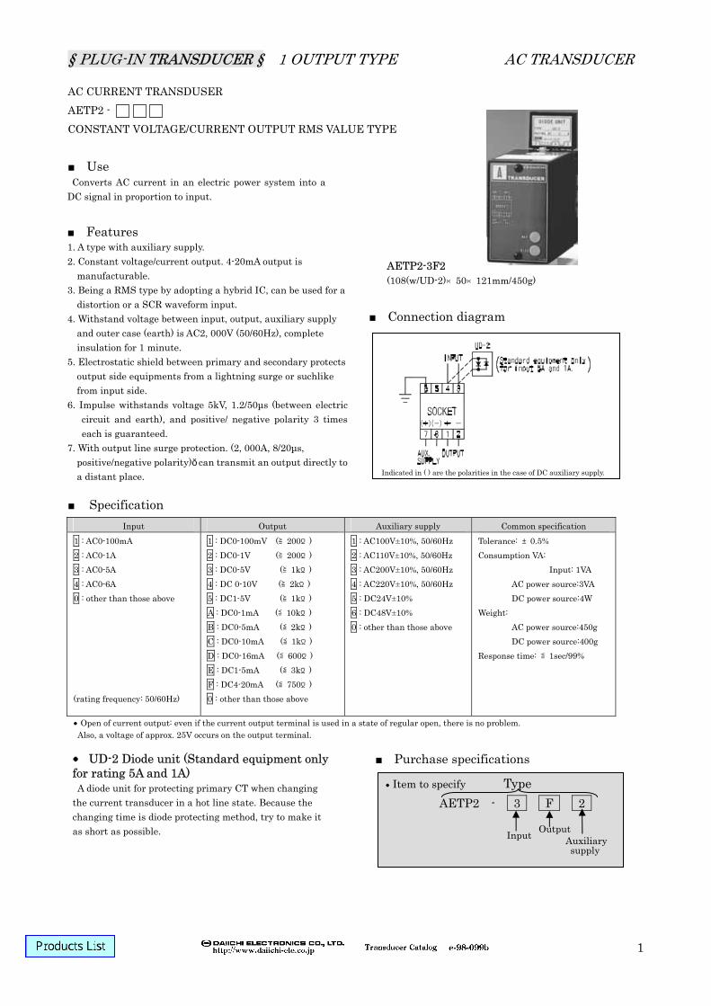
AC current transducer AETP2 - Outputs a DC signal which was proportional to RMS value of an AC current input. AC2000V
AC voltage transducer VETP2 - Outputs a DC signal which was proportional to RMS value of an AC voltage input. AC2000V
Frequency transducer FTP2 - Outputs a DC signal which was proportional to frequency. AC2000V AC current transducer ATP2 - Outputs a DC signal which was proportional to AC current.
Power-free Constant current output AC2000V AC voltage transducer VTP2 - Outputs a DC signal which was proportional to AC voltage.
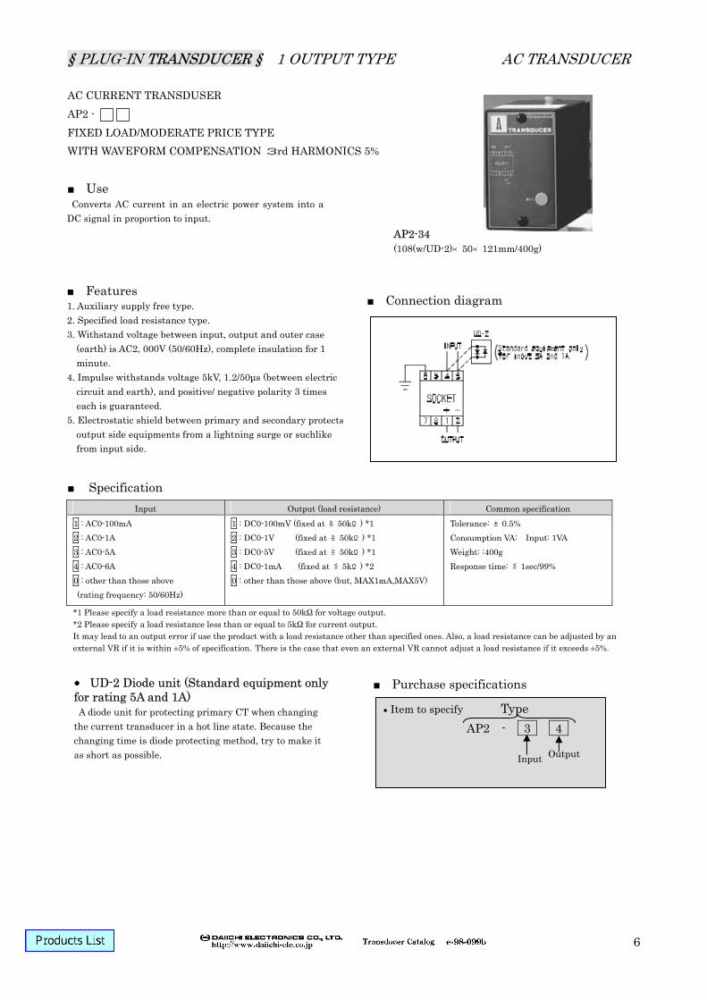
Power-free Constant current output AC2000V AC current transducer AP2 - Outputs a DC signal which was proportional to AC current.
Power-free Load fixed type. AC2000V AC voltage transducer VP2 - Outputs a DC signal which was proportional to AC voltage.
Power-free Load fixed type. AC2000V DC power transducer DWP1 - Outputs a DC signal which was proportional to DC power. AC1500V
1
§ PLUG-IN TRANSDUCER § COMPENDIUM
PLUG-IN 2-OUTPUT TYPE Signal/Sensor/AC transducer
Product Type code Outlines Withstand voltage
Isolator WTP2 -
Converts a DC input signal into a unified signal which was isolated. AC2000V
Distributor WDTP2 -C7 Supplies electric power to a 2-wire transmitter and converts signal from the transmitter into a proportional DC signal. AC2000V
Distributor with square root extraction
WSRDTP2-C7 Supplies electric power to a 2-wire transmitter and converts signal from the transmitter into a DC signal which was proportional to the square root of the signal.
AC2000V
Thermoelectric temperature transducer
WHTP2 - Converts thermal electromotive force of a thermocouple into a DC signal which was proportional to temperature. AC2000V
Resistance temperature transducer
WRHTP2- Converts resistance of a 3-wire thermal resistance into a DC signal which was proportional to temperature. AC2000V
Potentiometer transducer WRTP2 -Z Outputs a DC signal which was proportional to resistance of a
potentiometer. AC2000V AC current transducer WAETP2 - Outputs a DC signal which was proportional to RMS value of
an AC current input. AC2000V AC voltage transducer WVETP2 - Outputs a DC signal which was proportional to RMS value of
an AC voltage input. AC2000V Frequency transducer WFTP2 - Outputs a DC signal which was proportional to frequency. AC2000V Soft spec type
Product Type code Outlines Withstand voltage
Adding/subtracting transducer
CADTP1 -
Does adding and subtracting of three inputs, and then outputs a DC signal equivalent to the value. Parameters can be changed by CCM-1.
AC1500V
Multiplying/dividing transducer
CMLTP1 -
Does multiplication and division of three inputs, and then outputs a DC signal equivalent to the value. Parameters can be changed by CCM-1.
AC1500V
Temperature/pressure correcting transducer
CLTP1 - Processes temperature/pressure condition and converts it into a DC signal which was proportional to flow rate. Parameters can be changed by CCM-1.
AC1500V
Function generating transducer
CFGTP1 - Does broken line operation of a DC input 15 polygonal lines maximum. Parameters can be changed by CCM-1 AC1500V
Analog backup transducer
CAMTP1 - Provides output with a backup when a computer or a PID controller was down. Follow-up movement and output backup are settable by CCM-1.
AC1500V
Voltage pulse transducer CVFTP1 - Outputs a pulse of frequency which was proportional to a DC
input. Pulse frequency, pulse width and output cut against a low input are settable by CCM-1.
AC1500V
Alarm setter
Product Type code Outlines Withstand voltage
Alarm setter (digital % scale)
SDD--105- Compares a preset value of digital % scale with a direct input signal, and outputs a contact signal. AC1500V
Alarm setter (actual scale)
SD--105- Compares value of an actual scale setter with a direct input signal, and outputs a contact signal. AC1500V
Alarm setter (LCD)
SDLC-105- Compares a preset value with a direct input signal, and then outputs a contact signal. 4 digit LCD indication. Actual scale indication is settable.
AC2000V
Deviation alarm setter (LCD)
SDDV-105- Compares deviation between two DC signal inputs and deviation of each input with a preset value, and then outputs a contact signal.
AC2000V
AC voltage alarm setter SVD--105- Inputs AC voltage and outputs a contact signal AC2000V
2
§ PLUG-IN TRANSDUCER § COMMON STANDARD SPECIFICATION/TYPE CODE DESIGNATION
Common standard specifications High quality/high reliability Highly reliable electronic parts are adopted. Aging tests of each part as well as burn-in aging test of the product under a high temperature are implemented. PCB treatment In order to reinforce insulation resistance stability of PCB surfaces and prevent the surfaces from insulation deterioration, B side of the PCB was cleaned and coated with high humidity resistant varnish after parts installation. Output limiter circuit Even if an excessive input is applied, the product confines the output to about 1.5 times of rating and protects the output side equipments.
Item Specification Tolerance % against output span Influence of temperature 23±10 tolerance % Influence of frequency 45-65Hz tolerance % (Reference) IEC, rated Hz±10% tolerance % Characteristics In conformity with JIS C 1111-1989 in tolerance
Response time Time it takes to fall within ±1% of the final steady-state when applied a stepped input. Standard : ≦1.0. sec. (Insulation transducer only: ≦0.5 sec.)
Output ripple ≦1%p-p against output span External adjustment of output
±5% adjustable
Auxiliary supply AC100V or AC200V ±10% (50, 60Hz) (DC100/110V is manufacturable only for TP2) Input 2 times (10 sec.), 1.2 times (continuity) of rated voltage
Overvoltage Aux.supply 1.5 times (10 sec.), 1.1 times (continuity) of rated voltage
AC transducer 40 times (1 sec.), 20 times (4 sec.) 10 times (16 sec.), 1, 2 times (continuity) of rated current Over current
Signal transducer 10 times (5 sec.)
Insulation resistance Between input terminal, output terminal, (auxiliary supply terminal) and outer case (earth) ≧50MΩ at DC500V. Non-insulation type: input terminal and output terminal conducted.
Material of outer case Fire-retardant ABS resin Outer case Black (N 1.5)
Appearance color Rating plate Dark blue (5PB 2/6)
Operating temperature/ humidity range
-10-+55, 30-85%RH
Storage temperature range
-40-+70
Type code designation 1 output type Signal transducer
(1) P (2) – (3) (4) (5)
3
§ PLUG-IN TRANSDUCER § COMMON STANDARD SPECIFICATION/TYPE CODE DESIGNATION
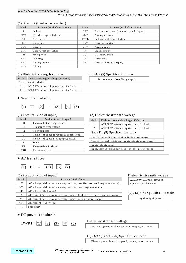
(1) Product (kind of conversion)
Mark Product (kind of conversion) Mark Product (kind of conversion) T Isolator CRT Constant response (constant speed response)
HST Ultrahigh speed isolator AMT Analog memory DT Distributor T***L Isolator with lower limiter LT Linearizer RVT Reverse isolator
SQT Square VFT Analog pulse SRT Square root extraction R Signal switch MT Multiplying UGT Ultraslow pulse DIT Dividing PRT Pulse rate ALT Analog limiter PPT Pulse isolator (2-output) ADT Adding
(2) Dielectric strength voltage (3) / (4) / (5) Specification code Mark Dielectric strength voltage (50/60Hz) None Non-insulation
1 AC1,500V between input/output, for 1 min. 2 AC2,000V between input/output, for 1 min. Sensor transducer (1) TP (2) – (3) (4) (5) (1) Product (kind of input) (2) Dielectric strength voltage
Mark Product (kind of input) H Thermoelectric temperature RH Resistance temperature R Potentiometer G Revolution-speed (Frequency proportion)
GV Revolution-speed (Voltage proportion) S Selsyn
SH Thermoelectric alarm SRH Platinum alarm
AC transducer (1) P2 – (2) (3) (4) (1) Product (kind of input) Dielectric strength voltage Mark Product (kind of input)
V AC voltage (with waveform compensation, load fixation, need no power source)VT AC voltage (with waveform compensation, need no power source)
VET AC voltage (RMS value) A AC current (with waveform compensation, load fixation, need no power source)
AT AC current (with waveform compensation, need no power source) AET AC current (RMS value) FT Frequency
DC power transducer DWP1 – (1) (2) (3) (4) (5)
Input/output/auxiliary supply
Mark Dielectric strength voltage (50/60Hz) 1 AC1,500V between input/output, for 1 min. 2 AC2,000V between input/output, for 1 min.
(3) / (4) / (5) Specification code Kind of thermocouple, input, output, power source Kind of thermal resistance, input, output, power source Input, output, power Input, normal operating voltage, output, power source
AC2,000V(50/60Hz) between input/output, for 1 min.
(2) / (3) / (4) Specification code
Input, output, power
Dielectric strength voltage AC1,500V(50/60Hz) between input/output, for 1 min.
(1) / (2) / (3) / (4) / (5) Specification code
Electric power, input 1, input 2, output, power source
4
§ PLUG-IN TRANSDUCER § COMMON STANDARD SPECIFICATION/TYPE CODE DESIGNATION
2-output type Signal transducer
W (1) P (2) – (3) (4) (5) (6) (1)Product (kind of conversion)
D With contact delay circuit (4) Input (5) Control power source Digital LCD type SDLC – 105 - (1) (2) Deviation alarm setter Pulse isolator SDDV 105 - (1) (2) PPTP2- (1) (2) Power source arrester Signal arrester AR - (1) DA - (1)
(1) Rated line voltage (1) Product (kind of conversion)
Mark Rated line voltage 100 AC100/110V 200 AC200/220V
DA - 1 (1)
Kind of power source rating
Mark Power source rating 1 ≦AC125V/DC180V 2 ≦AC250V 3 ≦DC30V
DA - 2 (1)
Kind of power source rating
Mark Power source rating 1 ≦AC125V/DC180V 2 ≦AC250V
(2) Setting Mark Setting HL Upper/lower limit setting HH Upper/upper limit setting LL Lower/lower limit setting H Upper limit setting L Lower limit setting
(1) Input (2) Control power source
(1) Input (2) Control power source
(1) Input (2) Control power source
Mark Product (kind of conversion) TP DC4-20mA HT Thermocouple RH Thermal resistance RT Potentiometer GT Pulse
6
§ PLUG-IN TRANSDUCER § 1 OUTPUT TYPE SIGNAL TRANSDUCER
1
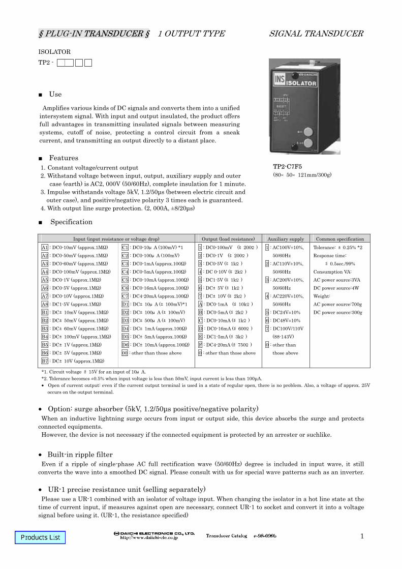
ISOLATOR TP2 -
Use
Features
Specification Option: surge absorber (5kV, 1.2/50µs positive/negative polarity) When an inductive lightning surge occurs from input or output side, this device absorbs the surge and protects
connected equipments. However, the device is not necessary if the connected equipment is protected by an arrester or suchlike.
Built-in ripple filter Even if a ripple of single-phase AC full rectification wave (50/60Hz) degree is included in input wave, it still
converts the wave into a smoothed DC signal. Please consult with us for special wave patterns such as an inverter. UR-1 precise resistance unit (selling separately) Please use a UR-1 combined with an isolator of voltage input. When changing the isolator in a hot line state at the
time of current input, if measures against open are necessary, connect UR-1 to socket and convert it into a voltage signal before using it. (UR-1, the resistance specified)
Amplifies various kinds of DC signals and converts them into a unified intersystem signal. With input and output insulated, the product offers full advantages in transmitting insulated signals between measuring systems, cutoff of noise, protecting a control circuit from a sneak current, and transmitting an output directly to a distant place.
1. Constant voltage/current output 2. Withstand voltage between input, output, auxiliary supply and outer
case (earth) is AC2, 000V (50/60Hz), complete insulation for 1 minute.3. Impulse withstands voltage 5kV, 1.2/50µs (between electric circuit and
outer case), and positive/negative polarity 3 times each is guaranteed. 4. With output line surge protection. (2, 000A, ±8/20µs)
1 : DC0-100mV (≧200Ω)2 : DC0-1V (≧200Ω) 3 : DC0-5V (≧1kΩ) 4 : DC 0-10V (≧2kΩ) 5 : DC1-5V (≧1kΩ) 6 : DC±5V (≧1kΩ) 7 : DC±10V (≧2kΩ) A : DC0-1mA (≦10kΩ) B : DC0-5mA (≦2kΩ) C : DC0-10mA (≦1kΩ) D : DC0-16mA (≦600Ω) E : DC1-5mA (≦3kΩ) F : DC4-20mA (≦750Ω) 0 : other than those above
1 : AC100V±10%, 50/60Hz
2 : AC110V±10%, 50/60Hz
3 : AC200V±10%, 50/60Hz
4 : AC220V±10%, 50/60Hz
5 : DC24V±10% 6 : DC48V±10% 7 : DC100V/110V
(88-143V) 0 : other than
those above
Tolerance: ±0.25% *2 Response time:
≦0.5sec./99% Consumption VA: AC power source:3VA DC power source:4W Weight: AC power source:700g DC power source:300g
*1. Circuit voltage ≦15V for an input of 10μA. *2. Tolerance becomes ±0.5% when input voltage is less than 50mV, input current is less than 100µA. Open of current output: even if the current output terminal is used in a state of regular open, there is no problem. Also, a voltage of approx. 25V
occurs on the output terminal.
§ PLUG-IN TRANSDUCER § 1 OUTPUT TYPE SIGNAL TRANSDUCER
Indicated in ( ) are the polarities in the case of DC auxiliary supply.
§ PLUG-IN TRANSDUCER § 1 OUTPUT TYPE SIGNAL TRANSDUCER
3
ULTRAHIGH SPEED ISOLATOR HSTP1 -
Use
Features
Specification Option: surge absorber (5kV, 1.2/50µs positive/negative polarity) When an inductive lightning surge occurs from input or output side, this device absorbs the surge and protects
connected equipments. However, the device is not necessary if the connected equipment is protected by an arrester or suchlike. Ultrahigh speed response Keep in mind that because this device is high speed response, its ripple-removal ability is not as high as those of
other models. UR-1 precise resistance unit (selling separately) Please use a UR-1 combined with an ultrahigh speed isolator of voltage input. When changing the ultrahigh speed
isolator in a hot line state at the time of current input, if measures against open are necessary, connect UR-1 to socket and convert it into a voltage signal before using it. (UR-1, the resistance specified)
Amplifies various kinds of DC signals and converts them into a unified intersystem signal at an ultrahigh speed. Because the device is high speed response (≦500μs/90%), it can be used for insulating a feedback signal of a control circuit and so on.
1. With built-in ultrahigh speed isolator. 2. Constant voltage/current output. 3. Withstand voltage between input, output, auxiliary supply and outer
case (earth) is AC1, 500V (50/60Hz), complete insulation for 1 minute.4. Impulse withstands voltage 5kV, 1.2/50µs (between electric circuit and
outer case), and positive/negative polarity 3 times each is guaranteed. 5. With output line surge protection. (2, 000A, ±8/20µs, positive/negative
polarity)
HSTP1-C7F1 (80×50×121mm/400g)
Input (input resistance or voltage drop) Output (load resistance) Auxiliary supply Common specification
1 : DC0-100mV (≧200Ω)2 : DC0-1V (≧200Ω) 3 : DC0-5V (≧1kΩ) 4 : DC 0-10V (≧2kΩ) 5 : DC1-5V (≧1kΩ) 6 : DC±5V (≧1kΩ) 7 : DC±10V (≧2kΩ) A : DC0-1mA (≦10kΩ) B : DC0-5mA (≦2kΩ) C : DC0-10mA (≦1kΩ) D : DC0-16mA (≦600Ω) E : DC1-5mA (≦3kΩ) F : DC4-20mA (≦750Ω) 0 : other than those above
1 : AC100V±10%, 50/60Hz
2 : AC110V±10%, 50/60Hz
3 : AC200V±10%, 50/60Hz
4 : AC220V±10%, 50/60Hz
5 : DC24V±10% 6 : DC48V±10% 0 : other than
those above
Tolerance: ±0.25% *2 Response time:
500μs/90% Consumption VA: AC power source:3VA DC power source:4W Weight: AC power source:400g DC power source:300g
*1. Circuit voltage ≦15V for an input of 10μA. *2. Tolerance becomes ±0.5% when input voltage is less than 50mV; input current is less than 100μA. Open of current output: even if the current output terminal is used in a state of regular open, there is no problem. Also, a voltage of approx. 25V
occurs on the output terminal.
§ PLUG-IN TRANSDUCER § 1 OUTPUT TYPE SIGNAL TRANSDUCER
4
Connection diagram Block diagram
Purchase specifications
Type HSTP1 - C 7 F 1 S
Surge absorber (option) Input Output
Auxiliary supply
① Low-drift amplifying circuit ② Output circuit ③ Output line surge protection circuit ④ Insulated power source circuit
Indicated in ( ) are the polarities in the case of DC auxiliary supply.
§ PLUG-IN TRANSDUCER § 1 OUTPUT TYPE SIGNAL TRANSDUCER
5
PULSE ISOLATOR PPTP2 - Connection diagram Use Features
Specification At the time of Tr. open collector output Block diagram
At the time of relay contact output
Insulates and outputs an input pulse signal by a 2-output relay contact or an open collector.
1. Withstand voltage between input, 1st output, 2nd output and power source is AC2, 000V (50/60Hz), complete insulation for 1 minute.
2. Impulse withstands voltage 5kV, 1.2/50µs (between electric circuit and outer case), and positive/negative polarity 3 times each is guaranteed.
3. Product with output by an open collector or a relay contact is manufacturable.
Input Mark Output Mark Auxiliary supply 1 AC100V(-15%, +10%), 50/60Hz
3 Relay contact (2a) AC 100V 2A DC 24V 2A 0 other than those above
Maximum frequency Open collector output: 40Hz Relay contact output : 1Hz Minimum pulse width: 20ms
Response time Open collector output: ≦3ms Relay contact output: ≦10ms
Consumption VA: AC power source:2.5VA DC power source:1.5W
Weight: AC power source:500g DC power source:400g
About output pulse
Load operates when internal transistor Q is ON. Maximum switching capacity of internal transistor Q is DC24V, 100mA. Do not apply a reverse polarity voltage.
About output pulse
Load operates when contact is ON. Relay capacity: AC 100V, 2A
DC 24V, 2 Mechanical life: ≧50,000,000 times Electrical life: ≧100, 000 times (Rated load)
Input terminal open voltage 24V Input terminal shot current 5mA
①Constant current circuit ②Voltage converter ③Comparator ④Switching circuit ⑤Relay ⑥Current insulating circuit ⑦Power source circuit ⑧Reference voltage circuit ⑨Photo coupler
Purchase specifications
Item to specify PPTP2 - Output Auxiliary power
§ PLUG-IN TRANSDUCER § 1 OUTPUT TYPE SIGNAL TRANSDUCER
Amplifies various kinds of DC signals and converts them into a unified intersystem signal. Can be used for unification of signals or V-I conversion in a system.
1. Constant voltage/current output 2. Withstand voltage between electric circuit and
outer case is AC2, 000V (50/60Hz) for 1 minute, or between input/output and auxiliary supply AC1, 500V (50/60Hz) for 1 minute. It is not insulated between input and output.
3. Impulse withstands voltage 5kV, 1.2/50µs (between electric circuit and outer case), and positive/negative polarity 3 times each is guaranteed.
1 : DC0-100mV (≧200Ω)2 : DC0-1V (≧200Ω) 3 : DC0-5V (≧1kΩ) 4 : DC 0-10V (≧2kΩ) 5 : DC1-5V (≧1kΩ) 6 : DC±5V (≧1kΩ) 7 : DC±10V (≧2kΩ) A : DC0-1mA (≦10kΩ) B : DC0-5mA (≦2kΩ) C : DC0-10mA (≦1kΩ) D : DC0-16mA (≦600Ω) E : DC1-5mA (≦3kΩ) F : DC4-20mA (≦750Ω) 0 : other than those above
1 : AC100V±10%, 50/60Hz
2 : AC110V±10%, 50/60Hz
3 : AC200V±10%, 50/60Hz
4 : AC220V±10%, 50/60Hz
5 : DC24V±10% 6 : DC48V±10% 0 : other than
those above
Tolerance: ±0.25% *2 Response time:
≦0.5sec./99% Consumption VA: AC power source:3VA DC power source:4W Weight: AC power source:400g DC power source:250g
*1. Circuit voltage ≦15V for an input of 10μA. *2. Tolerance becomes ±0.5% when input voltage is less than 50mV, input current is less than 100µA. Open of current output: even if the current output terminal is used in a state of regular open, there is no problem. Also, a voltage of approx. 25V
occurs on the output terminal.
Item to specify
TP - C 7 F 5
Indicated in ( ) are the polarities in the case of DC auxiliary supply.
Input Output
Auxiliary supply
Even if a ripple of single-phase AC full rectification wave (50/60Hz) degree is included in input wave, it still converts the wave into a smoothed DC signal. Please consult with us for special wave patterns such as an inverter.
Please use a UR-1 combined with a DC transducer of voltage input. When changing the DC transducer in a hot line state at the time of current input, if measures against open are necessary, connect UR-1 to socket and convert it into a voltage signal before using it. (UR-1, the resistance specified)
Purchase specifications
①Low-drift amplifying circuit ②Output circuit ③Insulated power source circuit
§ PLUG-IN TRANSDUCER § 1 OUTPUT TYPE SIGNAL TRANSDUCER
7
INSULATION TYPE DISTRIBUTOR DTP2 – C 1
Use
Features Connection diagram
Specification Built-in ripple filter Block diagram Withstand voltage Insulation resistance
Supplies electrical power to a 2-wire transmitter receives a DC4-20mA signal from the transmitter and outputs a proportional DC signal.
1. Equipped with functions both of a distributor and a signal exchanger, the transducer is for a 2-wire transmitter's use.
2. Short-circuit protection function for transmitter circuit (≦30mA) .
3. Supplies a 2-wire transmitter with a stable power source.
4. Impulse withstands voltage 5kV, 1.2/50µs (between electric circuit and outer case) positive/ negative polarity 3 times each is guaranteed.
DTP2-C1F1 (80×50×121mm/650g)
Input Output (load resistance) Auxiliary supply Common specification
DC4-20mA (approx.100Ω)
1 : DC0-100mV (≧200Ω) 2 : DC0-1V (≧200Ω) 3 : DC0-5V (≧1kΩ) 4 : DC 0-10V (≧2kΩ) 5 : DC1-5V (≧1kΩ) A : DC0-1mA (≦10kΩ) B : DC0-5mA (≦2kΩ) C : DC0-10mA (≦1kΩ) D : DC0-16mA (≦600Ω) E : DC1-5mA (≦3kΩ) F : DC4-20mA (≦750Ω) 0 : other than those above
1 : AC100V±10%, 50/60Hz 2 : AC110V±10%, 50/60Hz 3 : AC200V±10%, 50/60Hz 4 : AC220V±10%, 50/60Hz 0 : other than those above DC power source is not
manufacturable.
2-wire transmitter power source: DC24-28V (when there is no load)
Current capacity: DC22mA MAX Tolerance: ±0.25% Response time: ≦0.5sec./99% Weight: 650g Consumption VA: 5VA
Item to specify
DTP2 – C 1 F 1
Output Auxiliary supply
Even if a ripple of single-phase AC full rectification wave (50/60Hz) degree is included in input wave, it still converts the wave into a smoothed DC signal.
Between input/output/power source: ≧50MΩ (at DC500V)
Between electric circuit and outer case: ≧50MΩ (at DC500V)
AC2, 000V for 1 min, Between electric circuit and outer case:
AC2, 000V for 1 min,
§ PLUG-IN TRANSDUCER § 1 OUTPUT TYPE SIGNAL TRANSDUCER
8
DISTRIBUTOR DTP – C 1 0
Use
Features Connection diagram
Specification Built-in ripple filter Block diagram Withstand voltage Insulation resistance
Supplies electrical power to a 2-wire transmitter receives a DC4-20mA signal from the transmitter and outputs a proportional DC signal.(DC1-5V)
1. Supplies power to a 2-wire transmitter, receives a current output (DC4-20mA) from the transmitter and outputs a proportional DC signal (DC1-5V) by a precise resistance (250Ω)
2. Short-circuit protection function for transmitter circuit (≦30mA) .
3. Supplies a 2-wire transmitter with a stable power source.
4. Impulse withstands voltage 5kV, 1.2/50µs (between electric circuit and outer case) positive/ negative polarity 3 times each is guaranteed.
DTP-C102 (80×50×121mm/650g)
Input (input resistance)
Output (load resistance)
Auxiliary supply Common specification
C1 DC4-20mA (approx.250Ω) 0 DC1-5V (≧250kΩ)
1 : AC100V±10%, 50/60Hz 2 : AC110V±10%, 50/60Hz 3 : AC200V±10%, 50/60Hz 4 : AC220V±10%, 50/60Hz 0 : other than those above DC power source is not
manufacturable.
Tolerance: ±0.5% Response time: ≦0.5sec./99% 2-wire transmitter power source:
DC24―28V (when there is no load) Current capacity: DC22mA MAX Output impedance: approx. 250Ω Allowable load resistance: ≧250kΩ Weight: 650g Consumption VA: 2VA
* There is no input/output specification for DTP. Please specify auxiliary supply only.
Item to specify
DTP – C 1 0 2
Auxiliary supply
Even if a ripple of single-phase AC full rectification wave (50/60Hz) degree is included in input wave, it still converts the wave into a smoothed DC signal.
Between input/output/power source: ≧50MΩ (at DC500V)
Between electric circuit and outer case: ≧50MΩ (at DC500V)
Purchase specifications
①Power shedding circuit ②Output circuit ③Insulated power source circuit
Between input/output/power source: AC1, 500V for 1 min,
Between electric circuit and outer case: AC1, 500V for 1 min,
§ PLUG-IN TRANSDUCER § 1 OUTPUT TYPE SIGNAL TRANSDUCER
9
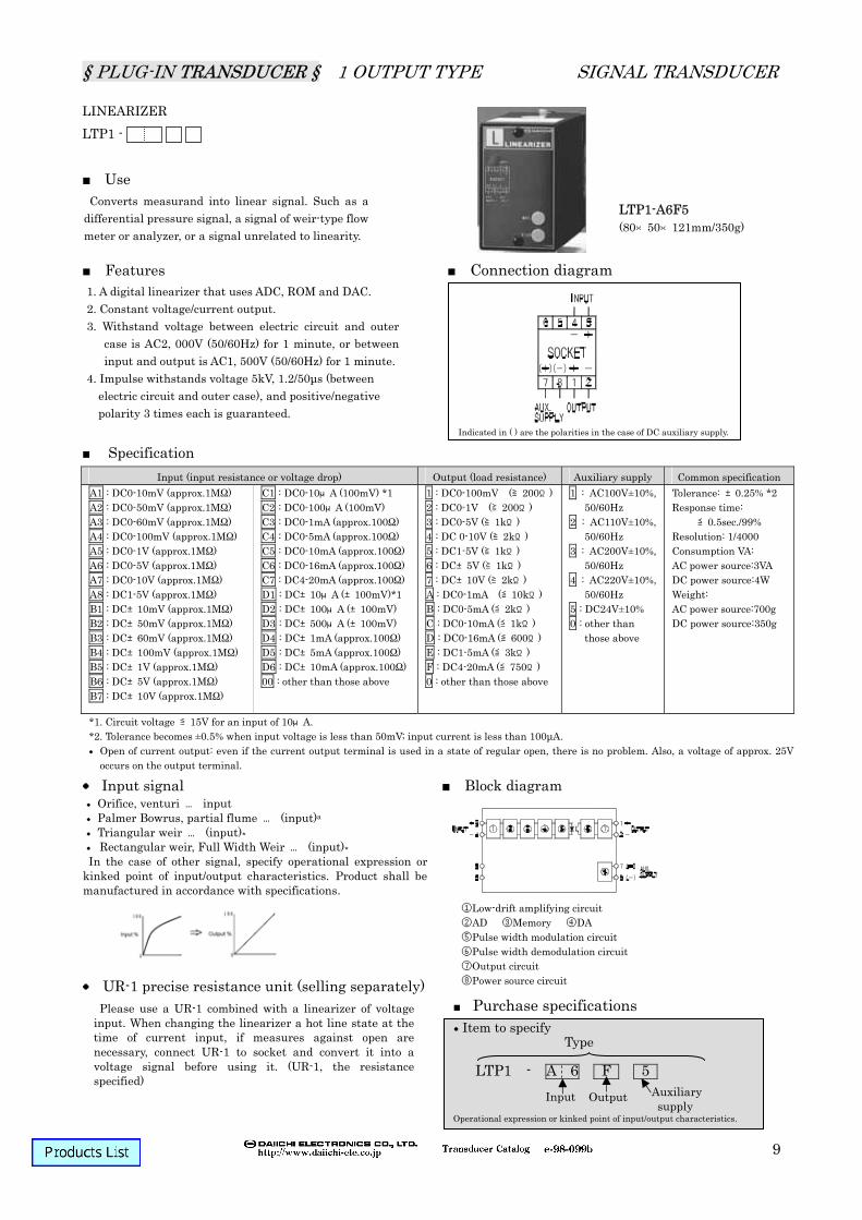
LINEARIZER LTP1 -
Use Features Connection diagram
Specification Input signal Block diagram
UR-1 precise resistance unit (selling separately)
Converts measurand into linear signal. Such as a differential pressure signal, a signal of weir-type flow meter or analyzer, or a signal unrelated to linearity.
1. A digital linearizer that uses ADC, ROM and DAC. 2. Constant voltage/current output. 3. Withstand voltage between electric circuit and outer
case is AC2, 000V (50/60Hz) for 1 minute, or between input and output is AC1, 500V (50/60Hz) for 1 minute.
4. Impulse withstands voltage 5kV, 1.2/50µs (between electric circuit and outer case), and positive/negative polarity 3 times each is guaranteed.
1 : DC0-100mV (≧200Ω)2 : DC0-1V (≧200Ω) 3 : DC0-5V (≧1kΩ) 4 : DC 0-10V (≧2kΩ) 5 : DC1-5V (≧1kΩ) 6 : DC±5V (≧1kΩ) 7 : DC±10V (≧2kΩ) A : DC0-1mA (≦10kΩ) B : DC0-5mA (≦2kΩ) C : DC0-10mA (≦1kΩ) D : DC0-16mA (≦600Ω) E : DC1-5mA (≦3kΩ) F : DC4-20mA (≦750Ω) 0 : other than those above
1 : AC100V±10%, 50/60Hz
2 : AC110V±10%, 50/60Hz
3 : AC200V±10%, 50/60Hz
4 : AC220V±10%, 50/60Hz
5 : DC24V±10% 0 : other than
those above
Tolerance: ±0.25% *2 Response time:
≦0.5sec./99% Resolution: 1/4000 Consumption VA: AC power source:3VA DC power source:4W Weight: AC power source:700g DC power source:350g
*1. Circuit voltage ≦15V for an input of 10μA. *2. Tolerance becomes ±0.5% when input voltage is less than 50mV; input current is less than 100µA. Open of current output: even if the current output terminal is used in a state of regular open, there is no problem. Also, a voltage of approx. 25V
occurs on the output terminal.
Item to specifyType
LTP1 - A 6 F 5
Indicated in ( ) are the polarities in the case of DC auxiliary supply.
Input Output Auxiliary supply
Orifice, venturi … input Palmer Bowrus, partial flume … (input)a Triangular weir … (input) Rectangular weir, Full Width Weir … (input) In the case of other signal, specify operational expression or
kinked point of input/output characteristics. Product shall be manufactured in accordance with specifications.
Please use a UR-1 combined with a linearizer of voltage input. When changing the linearizer a hot line state at the time of current input, if measures against open are necessary, connect UR-1 to socket and convert it into a voltage signal before using it. (UR-1, the resistance specified)
1 : DC0-100mV (≧200Ω)2 : DC0-1V (≧200Ω) 3 : DC0-5V (≧1kΩ) 4 : DC 0-10V (≧2kΩ) 5 : DC1-5V (≧1kΩ) A : DC0-1mA (≦10kΩ) B : DC0-5mA (≦2kΩ) C : DC0-10mA (≦1kΩ) D : DC0-16mA (≦600Ω) E : DC1-5mA (≦3kΩ) F : DC4-20mA (≦750Ω) 0 : other than those above
1 : AC100V±10%, 50/60Hz
2 : AC110V±10%, 50/60Hz
3 : AC200V±10%, 50/60Hz
4 : AC220V±10%, 50/60Hz
5 : DC24V±10% 6 : DC48V±10% 0 : other than
those above
Tolerance: ±0.25% *2 Response time:
≦0.5sec./99% Consumption VA: AC power source:3VA DC power source:4W Weight: AC power source:700g DC power source:350g
*1. Circuit voltage ≦15V for an input of 10μA. *2. Tolerance becomes ±0.5% when input voltage is less than 50mV; input current is less than 100µA. Open of current output: even if the current output terminal is used in a state of regular open, there is no problem. Also, a voltage of approx. 25V
occurs on the output terminal.
Item to specifyType
SQTP1 - A 8 F 5
Indicated in ( ) are the polarities in the case of DC auxiliary supply.
Please use a UR-1 combined with a square transducer of voltage input. When changing the square transducer in a hot line state at the time of current input, if measures against open are necessary, connect UR-1 to socket and convert it into a voltage signal before using it. (UR-1, the resistance specified)
Purchase specifications I-IB
IM-IB
§ PLUG-IN TRANSDUCER § 1 OUTPUT TYPE SIGNAL TRANSDUCER
Outputs a DC signal in proportion to square root of various kinds of DC signals.
1. Constant voltage/current output. 2. Withstand voltage between electric circuit and outer case
is AC1, 500V (50/60Hz) for 1 minute, or between input and output is AC1, 500V (50/60Hz) for 1 minute.
3. Output less than or equal to 10% shall be clamped at 0%.4. Plus/minus input is not manufacturable. 5. Impulse withstands voltage 5kV, 1.2/50µs (between
electric circuit and outer case), and positive/negative polarity 3 times each is guaranteed.
1 : DC0-100mV (≧200Ω)2 : DC0-1V (≧200Ω) 3 : DC0-5V (≧1kΩ) 4 : DC 0-10V (≧2kΩ) 5 : DC1-5V (≧1kΩ) A : DC0-1mA (≦10kΩ) B : DC0-5mA (≦2kΩ) C : DC0-10mA (≦1kΩ) D : DC0-16mA (≦600Ω) E : DC1-5mA (≦3kΩ) F : DC4-20mA (≦750Ω) 0 : other than those above
1 : AC100V±10%, 50/60Hz
2 : AC110V±10%, 50/60Hz
3 : AC200V±10%, 50/60Hz
4 : AC220V±10%, 50/60Hz
5 : DC24V±10% 6 : DC48V±10% 0 : other than
those above
Tolerance: ±0.25% *2 Response time:
≦0.5sec./99% Consumption VA: AC power source:3VA DC power source:4W Weight: AC power source:700g DC power source:350g
*1. Circuit voltage ≦15V for an input of 10μA. *2. Tolerance becomes ±0.5% when input voltage is less than 50mV; input current is less than 100µA. Open of current output: even if the current output terminal is used in a state of regular open, there is no problem. Also, a voltage of approx. 25V
occurs on the output terminal.
Item to specifyType
SRTP1 - C 5 F 5
Indicated in ( ) are the polarities in the case of DC auxiliary supply.
Please use a UR-1 combined with a square root extraction transducer of voltage input. When changing the square root extraction transducer in a hot line state at the time of current input, if measures against open are necessary, connect UR-1 to socket and convert it into a voltage signal before using it. (UR-1, the resistance specified)
Purchase specifications
§ PLUG-IN TRANSDUCER § 1 OUTPUT TYPE SIGNAL TRANSDUCER
Multiplies two DC signals and outputs a DC signal equivalent to the product.
1. Constant voltage/current output. 2. Withstand voltage between electric circuit and outer case,
and between input/output and auxiliary supply are AC1, 500V (50/60Hz) for 1 minute, or between input and output is AC1, 500V (50/60Hz) for 1 minute.
3. of Input X and Y are conducted inside the device. 4. Plus/minus input is not manufacturable. 5. Impulse withstands voltage 5kV, 1.2/50µs (between electric
circuit and outer case), and positive/negative polarity 3 times each is guaranteed.
1 : DC0-100mV (≧200Ω)2 : DC0-1V (≧200Ω) 3 : DC0-5V (≧1kΩ) 4 : DC 0-10V (≧2kΩ) 5 : DC1-5V (≧1kΩ) A : DC0-1mA (≦10kΩ) B : DC0-5mA (≦2kΩ) C : DC0-10mA (≦1kΩ) D : DC0-16mA (≦600Ω) E : DC1-5mA (≦3kΩ) F : DC4-20mA (≦750Ω) 0 : other than those above
1 : AC100V±10%, 50/60Hz
2 : AC110V±10%, 50/60Hz
3 : AC200V±10%, 50/60Hz
4 : AC220V±10%, 50/60Hz
5 : DC24V±10% 6 : DC48V±10% 0 : other than
those above
Tolerance: ±0.25% *2 Response time:
≦0.5sec./99% Consumption VA: AC power source:4VA DC power source:4W Weight: AC power source:700g DC power source:350g
*1. Circuit voltage ≦15V for an input of 10μA. *2. Tolerance becomes ±0.5% when input voltage is less than 50mV; input current is less than 100µA. Open of current output: even if the current output terminal is used in a state of regular open, there is no problem. Also, a voltage of approx. 25V
occurs on the output terminal. *3. Please specify the identical input X and Y.
Item to specifyType
MTP1 - A 6 F 5
Indicated in ( ) are the polarities in the case of DC auxiliary supply.
Please use a UR-1 combined with a multiplying transducer of voltage input. When changing the multiplying transducer in a hot line state at the time of current input, if measures against open are necessary, connect UR-1 to socket and convert it into a voltage signal before using it. (UR-1, the resistance specified)
Purchase specifications
XI-IB IM-IB
YI-IB IM-IB
§ PLUG-IN TRANSDUCER § 1 OUTPUT TYPE SIGNAL TRANSDUCER
Divides two DC signals and outputs a DC signal equivalent to the product.
1. Constant voltage/current output. 2. Withstand voltage between electric circuit and outer case, and
between input/output and auxiliary supply are AC1, 500V (50/60Hz) for 1 minute, or between input and output is AC1, 500V (50/60Hz) for 1 minute.
3. There is no regulation when input Y is less than or equal to 20%.4. of Input X and Y are conducted inside the device. 5. Plus/minus input is not manufacturable. 6. Impulse withstands voltage 5kV, 1.2/50µs (between electric
circuit and outer case), and positive/negative polarity 3 times each is guaranteed.
1 : DC0-100mV (≧200Ω)2 : DC0-1V (≧200Ω) 3 : DC0-5V (≧1kΩ) 4 : DC 0-10V (≧2kΩ) 5 : DC1-5V (≧1kΩ) A : DC0-1mA (≦10kΩ) B : DC0-5mA (≦2kΩ) C : DC0-10mA (≦1kΩ) D : DC0-16mA (≦600Ω) E : DC1-5mA (≦3kΩ) F : DC4-20mA (≦750Ω) 0 : other than those above
1 : AC100V±10%, 50/60Hz
2 : AC110V±10%, 50/60Hz
3 : AC200V±10%, 50/60Hz
4 : AC220V±10%, 50/60Hz
5 : DC24V±10% 6 : DC48V±10% 0 : other than
those above
Tolerance: ±0.25% *2 Response time:
≦0.5sec./99% Consumption VA: AC power source:4VA DC power source:4W Weight: AC power source:700g DC power source:350g
*1. Circuit voltage ≦15V for an input of 10μA. *2. Tolerance becomes ±0.5% when input voltage is less than 50mV; input current is less than 100µA. Open of current output: even if the current output terminal is used in a state of regular open, there is no problem. Also, a voltage of approx. 25V
occurs on the output terminal. *3. Please specify the identical input X and Y.
Item to specifyType
DITP1 - C 7 F 5
Indicated in ( ) are the polarities in the case of DC auxiliary supply.
Input Output Auxiliary supply
Input: IB~IM
Output: OB~OM O= ( )/ ( ) ×(OM-OB)+OB
IB: Min. input value. IM: Max. input value. OB: Min. output value. OM: Max. output value. XI: Input X YI: Input Y O: Output value.
Please use a UR-1 combined with a dividing transducer of voltage input. When changing the dividing transducer in a hot line state at the time of current input, if measures against open are necessary, connect UR-1 to socket and convert it into a voltage signal before using it. (UR-1, the resistance specified)
Purchase specifications
XI-IB IM-IB
YI-IB IM-IB
§ PLUG-IN TRANSDUCER § 1 OUTPUT TYPE SIGNAL TRANSDUCER
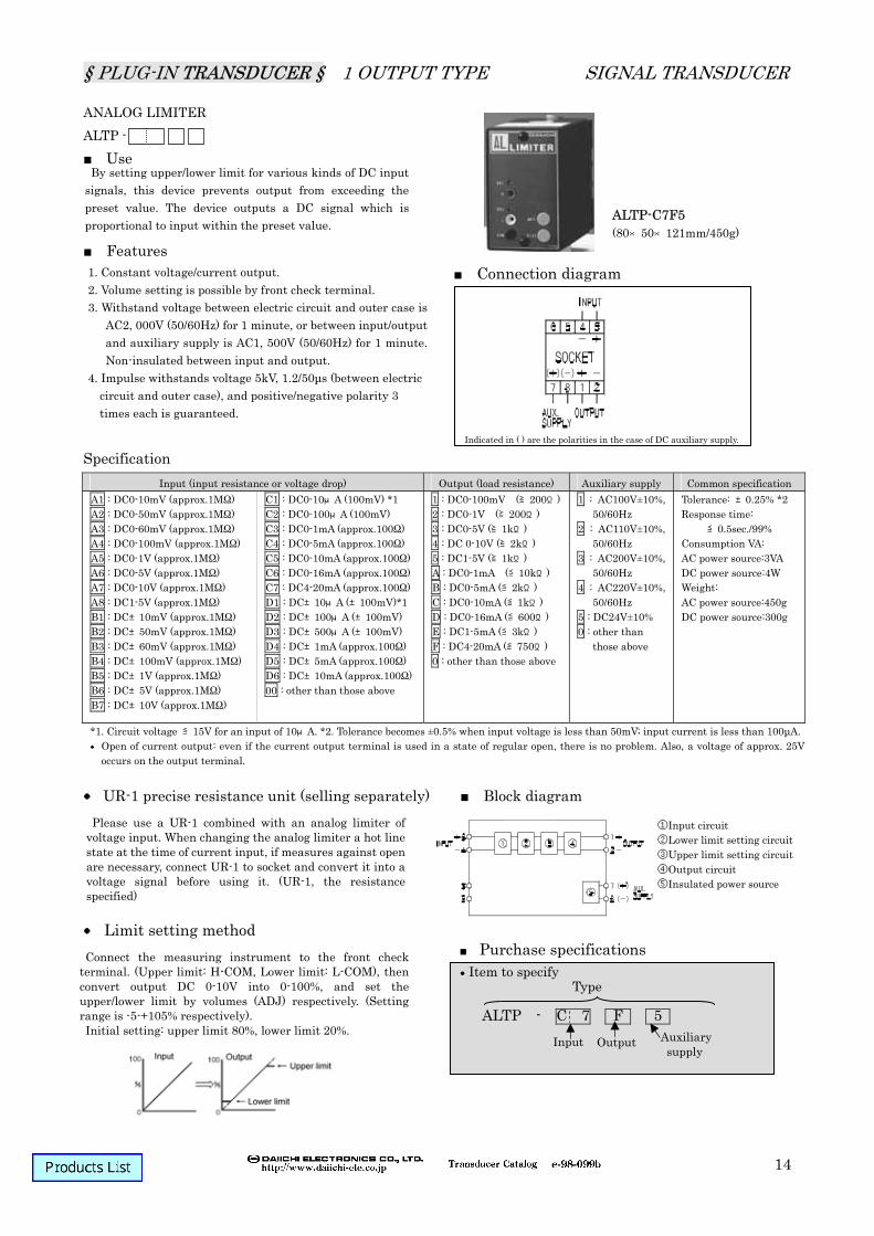
By setting upper/lower limit for various kinds of DC input signals, this device prevents output from exceeding the preset value. The device outputs a DC signal which is proportional to input within the preset value.
1. Constant voltage/current output. 2. Volume setting is possible by front check terminal. 3. Withstand voltage between electric circuit and outer case is
AC2, 000V (50/60Hz) for 1 minute, or between input/output and auxiliary supply is AC1, 500V (50/60Hz) for 1 minute. Non-insulated between input and output.
4. Impulse withstands voltage 5kV, 1.2/50µs (between electric circuit and outer case), and positive/negative polarity 3 times each is guaranteed.
1 : DC0-100mV (≧200Ω)2 : DC0-1V (≧200Ω) 3 : DC0-5V (≧1kΩ) 4 : DC 0-10V (≧2kΩ) 5 : DC1-5V (≧1kΩ) A : DC0-1mA (≦10kΩ) B : DC0-5mA (≦2kΩ) C : DC0-10mA (≦1kΩ) D : DC0-16mA (≦600Ω) E : DC1-5mA (≦3kΩ) F : DC4-20mA (≦750Ω) 0 : other than those above
1 : AC100V±10%, 50/60Hz
2 : AC110V±10%, 50/60Hz
3 : AC200V±10%, 50/60Hz
4 : AC220V±10%, 50/60Hz
5 : DC24V±10% 0 : other than
those above
Tolerance: ±0.25% *2 Response time:
≦0.5sec./99% Consumption VA: AC power source:3VA DC power source:4W Weight: AC power source:450g DC power source:300g
*1. Circuit voltage ≦15V for an input of 10μA. *2. Tolerance becomes ±0.5% when input voltage is less than 50mV; input current is less than 100µA. Open of current output: even if the current output terminal is used in a state of regular open, there is no problem. Also, a voltage of approx. 25V
occurs on the output terminal.
Item to specifyType
ALTP - C 7 F 5
Indicated in ( ) are the polarities in the case of DC auxiliary supply.
Input Output Auxiliary supply
Connect the measuring instrument to the front check terminal. (Upper limit: H-COM, Lower limit: L-COM), then convert output DC 0-10V into 0-100%, and set the upper/lower limit by volumes (ADJ) respectively. (Setting range is -5-+105% respectively). Initial setting: upper limit 80%, lower limit 20%.
Please use a UR-1 combined with an analog limiter of voltage input. When changing the analog limiter a hot line state at the time of current input, if measures against open are necessary, connect UR-1 to socket and convert it into a voltage signal before using it. (UR-1, the resistance specified)
①Input circuit ②Lower limit setting circuit ③Upper limit setting circuit ④Output circuit ⑤Insulated power source i i
Purchase specifications
§ PLUG-IN TRANSDUCER § 1 OUTPUT TYPE SIGNAL TRANSDUCER
15
ADDING TRANSDUCER ADTP1 -
Use Features
Connection diagram
Specification Item to be specified Block diagram
Adds two DC signals and outputs a DC signal equivalent to the sum.
1. Constant voltage/current output. 2. Withstand voltage between input/output and auxiliary supply,
and between input and output are AC1, 500V (50/60Hz) for 1 minute, or between electric circuit and outer case is AC2, 000V (50/60Hz) for 1 minute.
3. of Input 1 and 2 are conducted inside the device. 4. Plus/minus input is manufacturable. 5. Impulse withstands voltage 5kV, 1.2/50µs (between electric
circuit and outer case), and positive/negative polarity 3 times each is guaranteed.
1 : DC0-100mV (≧200Ω)2 : DC0-1V (≧200Ω) 3 : DC0-5V (≧1kΩ) 4 : DC 0-10V (≧2kΩ) 5 : DC1-5V (≧1kΩ) A : DC0-1mA (≦10kΩ) B : DC0-5mA (≦2kΩ) C : DC0-10mA (≦1kΩ) D : DC0-16mA (≦600Ω) E : DC1-5mA (≦3kΩ) F : DC4-20mA (≦750Ω) 0 : other than those above
1 : AC100V±10%, 50/60Hz
2 : AC110V±10%, 50/60Hz
3 : AC200V±10%, 50/60Hz
4 : AC220V±10%, 50/60Hz
5 : DC24V±10% 6 : DC48V±10% 0 : other than
those above
Tolerance: ±0.25% *2 Response time:
≦0.1sec./99% Consumption VA: AC power source:4VA DC power source:4W Weight: AC power source:500g DC power source:350g
*1. Circuit voltage ≦15V for an input of 10μA. *2. Tolerance becomes ±0.5% when input voltage is less than 50mV; input current is less than 100µA. Open of current output: even if the current output terminal is used in a state of regular open, there is no problem. Also, a voltage of approx. 25V
occurs on the output terminal. *3. Please specify the identical input 1 and 2. Even if the input circuit is broken as 4-20mA input or 1-5V input becomes 0mA (0V), it is processed a
signal as 4mA (1V) input equivalency.
Item to specifyType
ADTP1 - C 7 F 5
Indicated in ( ) are the polarities in the case of DC auxiliary supply.
Input Output Auxiliary supply
(1)Addition ratio standard 1: 1= 2 Example: electric power
Input 1 (1kW) 5V Input 2 (1kW) 5V Output (2kW) 5V
(2) Addition ratio special 1: 1= 1
Input 1 (1kW) 5V Input 2 (1kW) 5V Output (1kW) 5V
However, the 5V output saturates at about 150% (7.5V).(3) Addition ratio special 1: 2 = 3
Please specify when the addition ratio is special.
§ PLUG-IN TRANSDUCER § 1 OUTPUT TYPE SIGNAL TRANSDUCER
16
CONSTANT RESPONSE CRTP -
Use
Features Connection diagram
Specification UR-1 precise resistance unit (selling separately) Block diagram
Response speed
Against various kinds of DC input signals which are taking a sudden change, this converter provides a DC output changing at a preset constant speed.
1. Time is settable from front. 2. Constant voltage/current output. 3. Withstand voltage between electric circuit and outer case is
AC2, 000V (50/60Hz) for 1 minute, or between input/output and auxiliary supply is AC1, 500V (50/60Hz) for 1 minute. Non-insulated between input and output.
4. Impulse withstands voltage 5kV, 1.2/50µs (between electric circuit and outer case), and positive/negative polarity 3 times each is guaranteed.
1 : DC0-100mV (≧200Ω)2 : DC0-1V (≧200Ω)3 : DC0-5V (≧1kΩ)4 : DC 0-10V (≧2kΩ)5 : DC1-5V (≧1kΩ)A : DC0-1mA (≦10kΩ)B : DC0-5mA (≦2kΩ)C : DC0-10mA (≦1kΩ)D : DC0-16mA (≦600Ω)E : DC1-5mA (≦3kΩ)F : DC4-20mA (≦750Ω)0 : other than those above
1 : AC100V±10%, 50/60Hz
2 : AC110V±10%, 50/60Hz
3 : AC200V±10%, 50/60Hz
4 : AC220V±10%, 50/60Hz
5 : DC24V±10% 0 : other than
those above
Tolerance: ±0.5% *2 Consumption VA: AC power source:3VA DC power source:4W Weight: AC power source:450g DC power source:300g
*1. Circuit voltage ≦15V for an input of 10μA. Open of current output: even if the current output terminal is used in a state of regular open, there is no problem. Also, a voltage of approx. 25V
occurs on the output terminal.
Item to specifyType
CRTP - C 6 F 5
Indicated in ( ) are the polarities in the case of DC auxiliary supply.
Input Output Auxiliary supply
Range of response time is 0.5-40 sec. (when changing input from 0 to 100%). Set it with the front volume.
Please use a UR-1 combined with a constant response of voltage input. When changing the constant response a hot line state at the time of current input, if measures against open are necessary, connect UR-1 to socket and convert it into a voltage signal before using it. (UR-1, the resistance specified)
①Low-drift amplifying circuit ②Ramp function generating
circuit ③Comparing circuit ④Output circuit ⑤Insulated power source circuit
Purchase specifications
The case of 40sec. setting.
§ PLUG-IN TRANSDUCER § 1 OUTPUT TYPE SIGNAL TRANSDUCER
17
ANALOG MEMORY AMTP -
Use
Connection diagram
Specification UR-1 precise resistance unit (selling separately) Block diagram
Limit setting method
Amplifies various kinds of DC signals and converts them into a unified intersystem signal. By ON→OFF operation between HOLD terminals, the device can hold the output at that time on a permanent basis.
Features 1. Constant voltage/current output. 2. Withstand voltage between electric circuit and outer case is
AC2, 000V (50/60Hz) for 1 minute, or between input/output and auxiliary supply is AC1, 500V (50/60Hz) for 1 minute. Non-insulated between input and output.
3. Impulse withstands voltage 5kV, 1.2/50µs (between electric circuit and outer case), and positive/negative polarity 3 times each is guaranteed.
1 : DC0-100mV (≧200Ω)2 : DC0-1V (≧200Ω)3 : DC0-5V (≧1kΩ)4 : DC 0-10V (≧2kΩ)5 : DC1-5V (≧1kΩ)A : DC0-1mA (≦10kΩ)B : DC0-5mA (≦2kΩ)C : DC0-10mA (≦1kΩ)D : DC0-16mA (≦600Ω)E : DC1-5mA (≦3kΩ)F : DC4-20mA (≦750Ω)0 : other than those above
1 : AC100V±10%, 50/60Hz
2 : AC110V±10%, 50/60Hz
3 : AC200V±10%, 50/60Hz
4 : AC220V±10%, 50/60Hz
5 : DC24V±10% 0 : other than
those above
Tolerance: ±0.5% *2 Response time:
≦0.5sec./99% Consumption VA: AC power source:3VA DC power source:4W Weight: AC power source:650g DC power source:300g
*1. Circuit voltage ≦15V for an input of 10μA. Open of current output: even if the current output terminal is used in a state of regular open, there is no problem. Also, a voltage of approx. 25V
occurs on the output terminal.
Item to specifyType
AMTP - C 7 F 5
Indicated in ( ) are the polarities in the case of DC auxiliary supply.
Input Output Auxiliary supply
Output becomes corresponding to input by turning HOLD terminal 5-6 ON, and it becomes HOLD output when HOLD terminal is turned OFF. Use a no-voltage contact input for input of HOLD terminal.Also, output becomes indefinite if reset power source in
memory state.
Please use a UR-1 combined with an analog memory of voltage input. When changing the analog memory a hot line state at the time of current input, if measures against open are necessary, connect UR-1 to socket and convert it into a voltage signal before using it. (UR-1, the resistance specified)
①Input circuit ②Counter ③DA converter ④Output circuit ⑤Comparator ⑥Insulated power
source circuit
Purchase specifications
§ PLUG-IN TRANSDUCER § 1 OUTPUT TYPE SIGNAL TRANSDUCER
18
ISOLATOR WITH LOWER LIMITER TP2 - L
Use Features
Specification Impulse withstand voltage Impulse withstands voltage between electric circuit and outer case (earth) 5kV, 1.2/50µs, and positive/negative polarity 3 times each is guaranteed. Option: surge absorber (5kV, 1.2/50µs positive/negative polarity 3 times each.) When an inductive lightning surge occurs from input or output side, this device absorbs the surge and protects
connected equipments. However, the device is not necessary if the connected equipment is protected by an arrester or suchlike.
Built-in ripple filter Even if a ripple of single-phase AC full rectification wave (50/60Hz) degree is included in input wave, it still
converts the wave into a smoothed DC signal. Please consult with us for special wave patterns such as an inverter.
A transducer which has a lower limit limiter (fixed) function included in output which is proportional to input.
1. Constant voltage/current output 2. Withstand voltage between input, output, auxiliary supply and outer
case (earth) is AC2, 000V (50/60Hz), complete insulation for 1 minute.3. Input/output line surge protection (2,000A, 8/20µs, positive/negative
polarity) 4. Lower limit limiter function. Output less than -1% against output 0―100% is not available. Consult us for a limiter value equal to or less than -1%.
≦0.5sec./99% Consumption VA: AC power source:3VA DC power source:3.5W Weight: AC power source:400g DC power source:300g
*1. Circuit voltage ≦15V for an input of 10μA. *2. Tolerance becomes ±0.5% when input voltage is less than 50mV, input current is less than 100µA. Open of current output: even if the current output terminal is used in a state of regular open, there is no problem. Also, a voltage of approx. 25V
occurs on the output terminal.
§ PLUG-IN TRANSDUCER § 1 OUTPUT TYPE SIGNAL TRANSDUCER
19
UR-1 precise resistance unit (selling separately) Please use a UR-1 combined with an insulated transducer of voltage input. When changing the insulated
transducer in a hot line state at the time of current input, if measures against open are necessary, connect UR-1 to socket and convert it into a voltage signal before using it. (UR-1, the resistance specified) Connection diagram Block diagram
Purchase specifications
Item to specify
TP2 - C 7 F 5 L S To specify for surge absorber (optional)
Indicated in ( ) are the polarities in the case of DC auxiliary supply.
Type
§ PLUG-IN TRANSDUCER § 1 OUTPUT TYPE SIGNAL TRANSDUCER
20
REVERSE ISOLATOR RVTP2 -
Use Features
Specification Impulse withstand voltage Impulse withstands voltage between electric circuit and outer case (earth) 5kV, 1.2/50µs, and positive/negative polarity 3 times each is guaranteed. Option: surge absorber (5kV, 1.2/50µs positive/negative polarity 3 times each.) When an inductive lightning surge occurs from input or output side, this device absorbs the surge and protects
connected equipments. However, the device is not necessary if the connected equipment is protected by an arrester or suchlike.
Built-in ripple filter Even if a ripple of single-phase AC full rectification wave (50/60Hz) degree is included in input wave, it still
converts the wave into a smoothed DC signal. Please consult with us for special wave patterns such as an inverter.
Converts and outputs various kinds of DC input and output signals into reverse relationship.
1. Constant voltage/current output 2. Withstand voltage between input, output, auxiliary supply and outer
case (earth) is AC2, 000V (50/60Hz), complete insulation for 1 minute.3. Input/output line surge protection (2,000A, 8/20µs, positive/negative
≦0.5sec./99% Consumption VA: AC power source:3VA DC power source:3.5W Weight: AC power source:400g DC power source:300g
*1. Circuit voltage ≦15V for an input of 10μA. *2. Tolerance becomes ±0.5% when input voltage is less than 50mV, input current is less than 100µA. Open of current output: even if the current output terminal is used in a state of regular open, there is no problem. Also, a voltage of approx. 25V
occurs on the output terminal.
§ PLUG-IN TRANSDUCER § 1 OUTPUT TYPE SIGNAL TRANSDUCER
21
UR-1 precise resistance unit (selling separately) Please use a UR-1 combined with an insulated transducer of voltage input. When changing the insulated
transducer in a hot line state at the time of current input, if measures against open are necessary, connect UR-1 to socket and convert it into a voltage signal before using it. (UR-1, the resistance specified) Connection diagram Block diagram
Purchase specifications
Item to specify
RVTP2 - C 7 F 5 S To specify for surge absorber (optional)
Indicated in ( ) are the polarities in the case of DC auxiliary supply.
Type
§ PLUG-IN TRANSDUCER § 1 OUTPUT TYPE SIGNAL TRANSDUCER
22
ANALOG PULSE TRANSDUCER VFTP2 – Use
Features
Specification Output pulse number Output pulse width
Inputs a DC signal of electric power or a current transducer, and converts the signal into a pulse of proportional frequency.
1. Either one of open collector output, voltage output and contact output is selectable as output signal method. In addition, in the case of AC auxiliary supply and open collector output, product equipped with a power source for external relay's (DC24V, 40mA MAX) is manufacturable.
2. Function of cutting output against low input 1-10%. 3. Impulse withstands voltage 5kV, 1.2/50µs (between electric circuit and earth)
positive/ negative polarity 3 times each is guaranteed.
VFTP2 -915 (80×50×133mm/400g)
Kind of input (input resistance)
Output signal method Auxiliary supply Common specification
2 : Tr. open collector(O.C.) DC48V, 100mA 3 : 1a contact (non-voltage contact) DC30V,2A 4 : With power source for external relay.
Tr. open collector(O.C.) DC24V, 40mA MAX, in the case of AC auxiliary supply only,
1 : AC100V+10%, -15% 50/60Hz
2 : AC110V+10%, -15% 50/60Hz
3 : AC200V+10%, -15% 50/60Hz
4 : AC220V+10%, -15% 50/60Hz
5 : DC24V+10%, -15% 6 : DC48V+10%, -15% 0 : other than those
above
Tolerance: ±0.25%
Response time:
100ms + Consumption VA: AC power source:2.5VA DC power source:3W With power source for external relay AC power source:3.5VA Weight: AC power source:500g
DC power source:400g
F.S. Output ≦5pps F. S. Output ≧5pps
1 Output frequency
F.S output of transistor open collector output, voltage pulse output is 0.004306-277.8pps; F.S output of 1a contact output, transistor open collector output with power source for external relay is 0.00001667-1.000pps.
§ PLUG-IN TRANSDUCER § 1 OUTPUT TYPE SIGNAL TRANSDUCER
23
Block diagram according to output At the time of Tr. open collector output
At the time of voltage pulse output
Block diagram of front panel Connection diagram
Block diagram
Item to specify Type
VFTP2 – 9 1 5
Number of output pulse in pps Cut value for low input (1-10%) It shall be 1% if not being specified. Please specify output pulse number by 4 effective digits. For example: 0.2778pps in the case of 0.27777…pps
Output cut against low input Adjusts output to zero with
CUTOUT ADJ/VR against 1-10% of rated input. OPERATION LED LED turns off during output cut
against low input. LED turns on during pulse output. (Green) It turns on when there is an
input which value is greater than low input cut value.
Input
§ PLUG-IN TRANSDUCER § 1 OUTPUT TYPE SIGNAL TRANSDUCER
24
ULTRASLOW PULSE TRANSDUCER UGTP2 - Use Features
Specification Block diagram Common specification
Purchase specifications
Converts an input into a DC signal in proportion to input pulse number, and outputs it. Input signal method is selectable from open collector, voltage pulse and 1a contact.
1. High accuracy transducer with tolerance of ±0.25% 2. Security design to have withstood voltage AC2, 000V between
input, output and power source. 3. Function of slowing down output when input pulse stops.4. Function of cutting low input frequency. (If cut value is not
specified, it does cut when input frequency is equal to or less than 0.5% and returns at 1 %.)
5. By sufficient derating of parts used and reduction of internal heat generation, a long product life is guaranteed.
6. Product with a selector to switch an output between DC4-20mA/DC1-5V is manufacturable.
UGTP2-1F1 (80×50×123mm/500g)
Input signal method Output (load resistance) Auxiliary supply Common specification 1 : Open collector DC12V, 30mA 2 : Voltage pulse 50Vp (≧12kΩ) 3 : Non-voltage contact DC12V, 30mA 0 : other than those above
1 : DC0-100mV (≧200Ω) 2 : DC0-1V (≧200Ω) 3 : DC0-5V (≧1kΩ) 4 : DC 0-10V (≧2kΩ) 5 : DC1-5V (≧1kΩ) A : DC0-1mA (≦12kΩ) B : DC0-5mA (≦2.4kΩ) C : DC0-10mA (≦1.2kΩ) D : DC0-16mA (≦750Ω) E : DC1-5mA (≦3kΩ) F : DC4-20mA (≦750Ω) H: DC4-20mA (≦800Ω) DC1-5V (≧250kΩ) SW switching 0 : other than those above
Tolerance: ±0.25% Sensor power: DC12V±10%, 30mA Consumption VA: AC power source:2.5VA DC power source:3.0W Weight: AC power source:500g DC power source:400g
Open of current output: even if the current output terminal is used in a state of regular open, there is no problem. Also, a voltage of approx. 31V occurs on the output terminal.
Range of input pulse number: minimum range 0-0.01pps, maximum range 0-50pps.Input pulse width: 30-80% of duty ratio of
rated input frequency.
Connection diagram
Open collector input Detection level: ON ≦200Ω
OFF ≧100kΩ Voltage input
Detection level: H level 5-50V L level 0-2V
No-voltage 1a contact input Detection level: ON ≦200Ω
OFF ≧100kΩ
Number of output pulse in pps Cut value for low input (1-10%) It shall be 1% if not being specified.
(cut when lower than or equal to 0.5%, returns at 1%)
§ PLUG-IN TRANSDUCER § 1 OUTPUT TYPE SIGNAL TRANSDUCER
25
PULSE RATE TRANSDUCER PRTP2 - Use Features
Specification Block diagram Common specification
Purchase specifications
Converts a pulse signal into another one with dividing the former one by n. Input is selectable from open collector, voltage pulse, 1a contact, output is selectable from open collector, voltage pulse, 1a contact and photo MOS relay.
1. Security design to have withstood voltage AC2, 000V between input, output and power source.
2. A sensor power source DC12V, 30mA as standard equipment. 3. Input within frequency 0.01―1kHz can be applied commonly.4. Abundant specifications to have input selectable from voltage pulse,
open collector no-voltage contact and output selectable from voltage pulse, open collector, 1a contact and photo MOS relay.
5. By sufficient derating of parts used and reduction of internal heat generation, a long product life is guaranteed.
PRTP2-141 (80×50×123mm/500g)
Input signal method Output (load resistance) Auxiliary supply Common specification 1 : Open collector DC12V, 30mA 2 : Voltage pulse 50Vp (approx.12kΩ) 3 : Non-voltage contact DC12V, 30mA 0 : other than those above
AC125V, 200mA 2,000,000 times (COSφ=1) 4 : Photo MOS relay
AC/DC125V, 70mA MAX. (resistance load) 5 : other than those above
1 : AC100V (+10%, -15%) 50/60Hz
2 : AC110V (+10%, -15%) 50/60Hz
3 : AC200V (+10%, -15%) 50/60Hz
4 : AC220V (+10%, -15%) 50/60Hz
5 : DC24V (+10%, -15%) 0 : other than those above
Sensor power: DC12V±10%, 30mA Consumption VA: AC power source:3.0VA DC power source:3.5VA Weight: AC power source:500g DC power source:400g
Item to specify Type PRTP2 - 1 4 1
Input signal method
Output Auxiliarysupply
①Input circuit ②Input pulse width fixation circuit③CPU operational circuit ④Output part ⑤Constant voltage circuit ⑥power source circuit ⑦Insulation transformer
Input frequency range: minimum range 0-0.01Hz, maximum range 0-1kHz Input pulse width: 30-80% of duty rate of
rated input frequency (1/frequency) Frequency dividing ratio (integer): 1-105
Connection diagram
Open collector input Detection level: ON ≦200Ω
OFF ≧100kΩ Voltage input
Detection level: H level ≧5-50V L level ≦0-2V
No-voltage 1a contact input Detection level:: ON ≦200Ω
OFF ≧100kΩ
Frequency dividing ratio (integer) Specify output pulse width within 0.5-300ms (±20%) *Output3 :50-300ms
§ PLUG-IN TRANSDUCER § 1 OUTPUT TYPE SENSOR TRANSDUCER
1
THERMOELECTRIC TEMPERATURE TRANSDUCER HTP1 -
Use
Features Connection diagram
Specification
By inputting thermal electromotive forces of various kinds of thermocouples based on the JIS, the device insulates and converts thermal electromotive force into an output proportional to temperature.
1. Constant voltage/current output 2. Withstand voltage between input, output, auxiliary supply and outer
case (earth) is AC1, 500V (50/60Hz), complete insulation for 1 minute.3. Impulse withstands voltage 5kV, 1.2/50μs (between electric circuit and
outer case), and positive/negative polarity 3 times each is guaranteed. 4. With output line surge protection (2,000A, 8/20μs, positive/negative
polarity), can transmit an output directly to a distant place.
HTP1-K8F5 (103(w/R.J.C)×50×121mm/350g)
Kind of thermocouple
Standard input range
Input Output (load resistance) Auxiliary supply Common specification
1 : DC0-100mV (≧200Ω) 2 : DC0-1V (≧200Ω) 3 : DC0-5V (≧1kΩ) 4 : DC 0-10V (≧2kΩ) 5 : DC1-5V (≧1kΩ) A : DC0-1mA (≦10kΩ) B : DC0-5mA (≦2kΩ) C : DC0-10mA (≦1kΩ) D : DC0-16mA (≦600Ω) E : DC1-5mA (≦3kΩ) F : DC4-20mA (≦750Ω) 0 : other than those above
1 : AC100V±10%, 50/60Hz 2 : AC110V±10%, 50/60Hz 3 : AC200V±10%, 50/60Hz 4 : AC220V±10%, 50/60Hz 5 : DC24V±10% 6 : DC48V±10% 0 : other than those above
Tolerance: ±0.5% *2 Response time:
≦1sec./99% Consumption VA: AC power source:3VA DC power source:4W Weight: AC power source:700g DC power source:350g
Open of current output: even if the current output terminal is used in a state of regular open, there is no problem. Also, a voltage of approx. 25V occurs on the output terminal.
Please consult with us for N thermocouple.
Indicated in ( ) are the polarities in the case of DC auxiliary supply.
§ PLUG-IN TRANSDUCER § 1 OUTPUT TYPE SENSOR TRANSDUCER
2
Purchase specification
Item to specify HTP1 - K 8 F 5
Kind of thermocouple Input Output Auxiliary
supply
Built-in linearizer Thermal electromotive force of a thermocouple is not
proportional to temperature. Thermal electromotive force is converted into an output proportional to temperature by a linearizer. Built-in burnout Detects disconnection of thermocouple and does
scale-out of output to positive (+) side. Scale-out to negative side is also manufacturable if specified. Cold junction compensation In principle, a thermocouple generates a thermal
electromotive force equivalent to V (T1) -V (T2) as the Vin. A sensor for compensation compensates for a thermal
electromotive force equivalent to V (T2) In the case of cold junction compensation, the sensor
for compensation is connected to terminal part (5・6), and it compensates for temperature of terminal (5・6) as temperature of input terminal (3・4).
External resistance range External resistance range is the resistance value of a
reciprocating circuit. The reciprocating circuit consists of thermocouple, compensating wire and connecting wire connected to a transducer. Use the product within an external resistance range less than or equal to 25Ω. Input wiring Because a signal of input wiring is very weak, try to
make the wirings away from noise sources such as an electrical power line, a precipitous voltage or a line with current fluctuation.
Compensating wire A compensating wire compensates for the temperature
difference between thermocouple terminals and transducer terminals. Because color (material) of compensating wire varies according to thermocouple type, choose a compensating wire compatible with thermocouple. Match positive/negative polarities when connecting.
Type
§ PLUG-IN TRANSDUCER § 1 OUTPUT TYPE SENSOR TRANSDUCER
3
RESISTANCE TEMPERATURE TRANSDUCER RHTP2 -
Use
Features Connection diagram
Specification
By inputting resistance value of a 3-wire thermal resistance based on the JIS, this device insulates and converts the resistance value into a DC signal proportional to temperature.
1. Constant voltage/current output. 2. Withstand voltage between input, output, auxiliary supply and outer
case (earth) is AC2, 000V (50/60Hz), complete insulation for 1 minute. 3. Impulse withstands voltage 5kV, 1.2/50μs (between electric circuit and
earth), and positive/negative polarity 3 times each is guaranteed. 4. With output line surge protection. (2, 000A, 8/20μs, positive/negative
polarity),can transmit an output directly to a distant place.
1 : DC0-100mV (≧200Ω)2 : DC0-1V (≧200Ω)3 : DC0-5V (≧1kΩ)4 : DC 0-10V (≧2kΩ)5 : DC1-5V (≧1kΩ)A : DC0-1mA (≦10kΩ)B : DC0-5mA (≦2kΩ)C : DC0-10mA (≦1kΩ)D : DC0-16mA (≦600Ω)E : DC1-5mA (≦3kΩ)F : DC4-20mA (≦750Ω)0 : other than those above
1 : AC100V±10%, 50/60Hz
2 : AC110V±10%, 50/60Hz
3 : AC200V±10%, 50/60Hz
4 : AC220V±10%, 50/60Hz
5 : DC24V±10% 6 : DC48V±10% 0 : other than
those above
Tolerance: ±0.5% Response time:
≦1sec./99% Consumption VA: AC power source:3VA DC power source:4W Weight: AC power source:450g DC power source:300g
*Operating temperature range of thermal resistance is -200+650. Open of current output: even if the current output terminal is used in a state of regular open, there is no problem. Also, a voltage of approx. 25V
occurs on the output terminal.
Indicated in ( ) are the polarities in the case of DC auxiliary supply.
§ PLUG-IN TRANSDUCER § 1 OUTPUT TYPE SENSOR TRANSDUCER
4
Purchase specifications
Item to specify Type
RHTP2 - 1 A 7 A 1
Kind of thermal resistance Input Output
Auxiliary supply
Built-in linearizer Resistance value of a thermal resistance is not
proportional to temperature. It is converted into an output proportional to temperature by a linearizer. Built-in burnout Detects disconnection of a thermal resistance and does
scale-out of output to positive (+) side. Scale-out to negative side is also manufacturable if
specified. Specified current Specified current is a current flowing into a thermal
resistance. Change of resistance value can be measured by voltage drop caused by the specified current. Standard specified current is 2mA.
Compensating wire A compensating wire compensates for the temperature
difference between thermocouple terminals and transducer terminals. Because color (material) of compensating wire varies according to thermocouple type, choose a compensating wire compatible with thermocouple. Match positive/negative polarities when connecting.
§ PLUG-IN TRANSDUCER § 1 OUTPUT TYPE SENSOR TRANSDUCER
5
POTENTIOMETER TRANSDUCER RTP2 -
Use Features Connection diagram
Specification
Replaces the input of mechanical displacement of an angle or a position with resistance value change, then insulates and converts it into a proportional DC signal.
1. Constant voltage/current output. 2. Can cope with resistance range 100Ω-10kΩof a potentiometer. (RTP2-Z type) 3. Withstand voltage between input, output, auxiliary supply and earth is AC2,
000V (50/60Hz), complete insulation for 1 minute. 4. Impulse withstands voltage 5kV, 1.2/50μs (between electric circuit and outer
case), and positive/negative polarity 3 times each is guaranteed. 5. With output line surge protection. (2, 000A, 8/20μs, positive/negative polarity),
can transmit an output directly to a distant place.
RTP2-ZF2 (80×50×121mm/450g)
Normal total resistance Input (specified current) External resistance Output
100Ω-10kΩ can be used under the following adjustment range.
0 :other than those above
1 : DC0-100mV (≧200Ω)2 : DC0-1V (≧200Ω)3 : DC0-5V (≧1kΩ)4 : DC 0-10V (≧2kΩ)5 : DC1-5V (≧1kΩ)A : DC0-1mA (≦10kΩ)B : DC0-5mA (≦2kΩ)C : DC0-10mA (≦1kΩ)D : DC0-16mA (≦600Ω)E : DC1-5mA (≦3kΩ)F : DC4-20mA (≦750Ω)0 : other than those above
1 : AC100V±10%, 50/60Hz
2 : AC110V±10%, 50/60Hz
3 : AC200V±10%, 50/60Hz
4 : AC220V±10%, 50/60Hz
5 : DC24V±10% 6 : DC48V±10% 0 : other than
those above
Tolerance: ±0. 5% Response time:
≦1sec./99% Consumption VA: AC power source:3.5VA DC power source:4W Weight: AC power source:450g DC power source:300g
Open of current output: even if the current output terminal is used in a state of regular open, there is no problem. Also, a voltage of approx. 25V occurs on the output terminal.
*1.Variable range of BIAS MAX for the following potentiometers are assumed to be ±15%: 50Ω, 80Ω,100Ω, 200Ω, 400Ω,500Ω, 1kΩ, 2kΩ,3kΩ, 5kΩ, 10kΩ.
Indicated in ( ) are the polarities in the case of DC auxiliary supply.
§ PLUG-IN TRANSDUCER § 1 OUTPUT TYPE SENSOR TRANSDUCER
6
Purchase specifications
Item to specify Type RTP2 - Z F 2
Input Output Auxiliary supply
Adjustment range of output signal Specify the actual use range and the normal resistance
value of a potentiometer in the case of use range other than those above.
①BIAS……0%, MAX.……100% Standard ②BIAS……0%, MAX.……50% ③BIAS……50%, MAX.……50% (parallel shift of ②) ④BIAS……50%, MAX.……100% (parallel shift of ①) *Being within 0-50% of input value is sufficient for adjusting the output value to 0%.
Block diagram (RTP2-Z type) Those other than Z type are of constant current method.
①Low-drift voltage amplifying circuit ②Pulse width modulation circuit ③Pulse width demodulation circuit ④Output circuit ⑤Output line surge protection circuit ⑥Insulated power source circuit
Because this device is potential-free type, product is shipped in input of 0-10kΩ/output of graph ① (standard) above. Notes: this device can not be used with a 2-wire potentiometer.
Input form BIAS adjustment range: 0-50% of input span Z (can be changed from the front of converter.)
MAX adjustment range: 50-100% of input span (can be changed from the front of converter.)
§ PLUG-IN TRANSDUCER § 1 OUTPUT TYPE SENSOR TRANSDUCER
7
REVOLUTION-SPEED TRANSDUSER GTP2 - FREQUENCY PROPORTION TYPE Use Features Connection diagram
Specification
Purchase specifications
Kind of input Response (99%)
Normal operating voltage range (input resistance) Output Auxiliary
supply Common
specification A :0-33.3Hz B :0-40Hz
≦2sec.
C :0-50Hz D :0-55Hz E :0-60Hz F :0-65Hz
≦1.5sec.
G :0-66.6Hz H :0-100Hz I :0-120Hz J :0-166.6Hz
≦1sec.
K :0-200Hz L :0-333.3Hz M :0-500Hz N :0-1kHz
≦0.5sec.
0 : other than those above
-
1 : 1-25V (approx.25kΩ) 2 : 2-50V (approx.50kΩ) 3 : 5-110V (approx.110kΩ) 4 : 10-220V (approx.220kΩ) 0 : other than those above
1 : DC0-100mV (≧200Ω)2 : DC0-1V (≧200Ω)3 : DC0-5V (≧1kΩ)4 : DC 0-10V (≧2kΩ)5 : DC1-5V (≧1kΩ)A : DC0-1mA (≦10kΩ)B : DC0-5mA (≦2kΩ)C : DC0-10mA (≦1kΩ)D : DC0-16mA (≦600Ω)E : DC1-5mA (≦3kΩ)F : DC4-20mA (≦750Ω)0 : other than those above
1 : AC100V±10%, 50/60Hz
2 : AC110V±10%, 50/60Hz
3 : AC200V±10%, 50/60Hz
4 : AC220V±10%, 50/60Hz
5 : DC24V±10% 6 : DC48V±10% 0 : other than
those above
Tolerance: ±0.5% Consumption VA: AC power source:1.5VA DC power source:3W Weight: AC power source:800g DC power source:450g
Open of current output: even if the current output terminal is used in a state of regular open, there is no problem. Also, a voltage of approx. 25V occurs on the output terminal.
Item to specify Type GTP2 - H 4 F 5
Normal operating voltage
Input Output Auxiliarysupply
Cutoff power (dead band voltage) At the time of zero revolution or a whit input, to prevent
malfunction in normal mode caused by an induced voltage, it makes output equivalent to zero revolution as cutoff voltage when input is less than or equal to half of the minimum normal operating voltage. Specify the cutoff voltage if the induced voltage exceeds it, please. In the case of a special input waveform Because this device does detection by a zero-cross point, use
GVTP2 for a special input waveform such as an inverter.
Inputs from a tacho-generator installed on a dynamo or suchlike, and convert the input into a DC signal in proportion to the number of revolutions (frequency).
1. Constant voltage/current output 2. Withstand voltage between input, output, auxiliary supply
and outer case (earth) is AC2, 000V (50/60Hz), complete insulation for 1 minute.
3. Impulse withstands voltage 5kV, 1.2/50μs (between electric circuit and earth), and positive/ negative polarity 3 times each is guaranteed.
4. With output line surge protection. (2, 000A, 8/20μs, positive/negative polarity),can transmit an output directly to a distant place.
GTP2-H4F5 (80×50×121mm/450g)
Indicated in ( ) are the polarities in the case of DC auxiliary supply.
§ PLUG-IN TRANSDUCER § 1 OUTPUT TYPE SENSOR TRANSDUCER
8
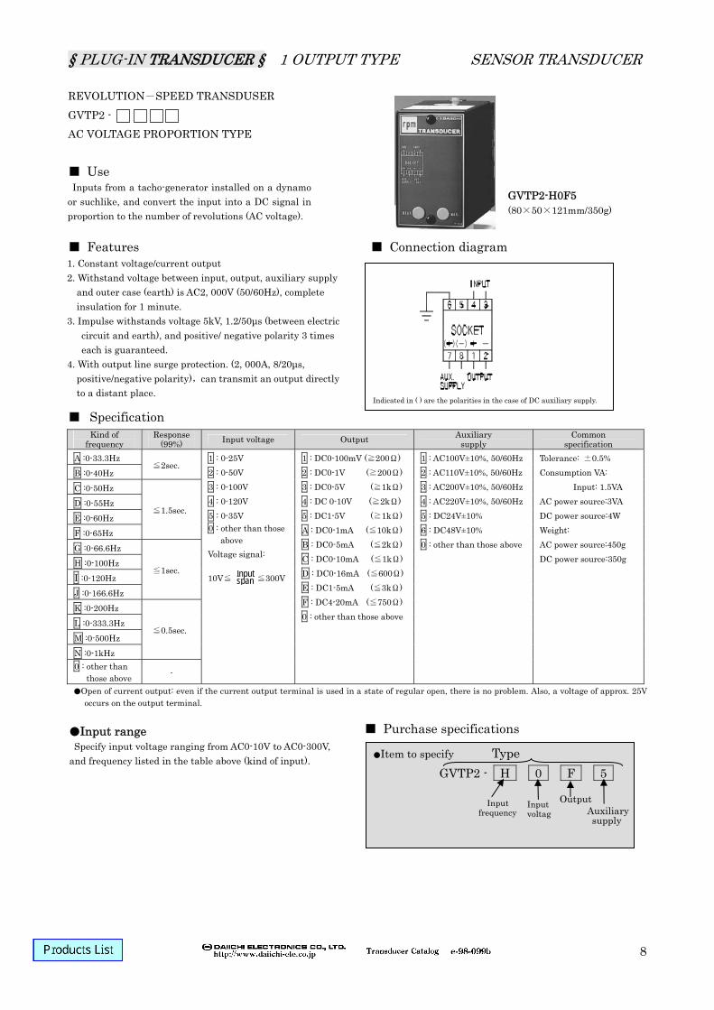
REVOLUTION-SPEED TRANSDUSER GVTP2 - AC VOLTAGE PROPORTION TYPE Use Features Connection diagram
Specification
Purchase specifications
Kind of frequency
Response (99%) Input voltage Output Auxiliary
supply Common
specification A :0-33.3Hz B :0-40Hz
≦2sec.
C :0-50Hz D :0-55Hz E :0-60Hz F :0-65Hz
≦1.5sec.
G :0-66.6Hz H :0-100Hz I :0-120Hz J :0-166.6Hz
≦1sec.
K :0-200Hz L :0-333.3Hz M :0-500Hz N :0-1kHz
≦0.5sec.
0 : other than those above -
1 : 0-25V 2 : 0-50V 3 : 0-100V 4 : 0-120V 5 : 0-35V 0 : other than those
above Voltage signal: 10V≦ ≦300V
1 : DC0-100mV (≧200Ω) 2 : DC0-1V (≧200Ω) 3 : DC0-5V (≧1kΩ) 4 : DC 0-10V (≧2kΩ) 5 : DC1-5V (≧1kΩ) A : DC0-1mA (≦10kΩ) B : DC0-5mA (≦2kΩ) C : DC0-10mA (≦1kΩ) D : DC0-16mA (≦600Ω) E : DC1-5mA (≦3kΩ) F : DC4-20mA (≦750Ω) 0 : other than those above
1 : AC100V±10%, 50/60Hz 2 : AC110V±10%, 50/60Hz 3 : AC200V±10%, 50/60Hz 4 : AC220V±10%, 50/60Hz 5 : DC24V±10% 6 : DC48V±10% 0 : other than those above
Tolerance: ±0.5% Consumption VA:
Input: 1.5VA AC power source:3VA DC power source:4W Weight: AC power source:450g DC power source:350g
Open of current output: even if the current output terminal is used in a state of regular open, there is no problem. Also, a voltage of approx. 25V occurs on the output terminal.
Item to specify Type GVTP2 - H 0 F 5
Input voltag
Output Auxiliarysupply
Input range Specify input voltage ranging from AC0-10V to AC0-300V,
and frequency listed in the table above (kind of input).
Inputs from a tacho-generator installed on a dynamo or suchlike, and convert the input into a DC signal in proportion to the number of revolutions (AC voltage).
1. Constant voltage/current output 2. Withstand voltage between input, output, auxiliary supply
and outer case (earth) is AC2, 000V (50/60Hz), complete insulation for 1 minute.
3. Impulse withstands voltage 5kV, 1.2/50μs (between electric circuit and earth), and positive/ negative polarity 3 times each is guaranteed.
4. With output line surge protection. (2, 000A, 8/20μs, positive/negative polarity),can transmit an output directly to a distant place.
GVTP2-H0F5 (80×50×121mm/350g)
Indicated in ( ) are the polarities in the case of DC auxiliary supply.
Input span
Input frequency
§ PLUG-IN TRANSDUCER § 1 OUTPUT TYPE SENSOR TRANSDUCER
9
SELSYN TRANSDUSER STP1 - Use Features Connection diagram
Specification
Purchase specifications
Input Output (load resistance) Auxiliary supply
Common specification
Selsyn signal 1 : 0-360°, 60Hz 2 : 0-360°, 50Hz 3 : 0-270°, 60Hz 4 : 0-270°, 50Hz 5 : 0-240°, 60Hz 6 : 0-240°, 50Hz 0 : other than those above
1 : DC0-100mV (≧200Ω) 2 : DC0-1V (≧200Ω) 3 : DC0-5V (≧1kΩ) 4 : DC 0-10V (≧2kΩ) 5 : DC1-5V (≧1kΩ) 6 : DC±5V (≧1kΩ) 7 : DC±10V (≧2kΩ) A : DC0-1mA (≦10kΩ) B : DC0-5mA (≦2kΩ) C : DC0-10mA (≦1kΩ) D : DC0-16mA (≦600Ω) E : DC1-5mA (≦3kΩ) F : DC4-20mA (≦750Ω) 0 : other than those above
1 : AC100V±10% 2 : AC110V±10% 3 : AC200V±10% 4 : AC220V±10% 0 : other than those above Power frequency becomes identical to input frequency.
Tolerance: ±0.5% Response time: ≦1sec./99% Consumption VA: AC power source:3.5VA Weight: AC power source:500g
Open of current output: even if the current output terminal is used in a state of regular open, there is no problem. Also, a voltage of approx. 25V occurs on the output terminal.
Manufacturable range (maximum value) is from 210° to 360° by a step of 30°. VR variable range ±20°-±30° is manufacturable.
Item to specify Type STP1 - 1 5 1
InputOutput
Auxiliary supply
Input/output relationship diagram
It replaces displacement of a revolution angle or a position of a selsyn communicator by DC signal of fine linearity.
1. Constant voltage/current output 2. Withstand voltage between electric circuit and outer case;
and between input, output, auxiliary supply is AC2, 000V (50/60Hz), or AC1, 500V (50/60Hz) for 1 minute between input and output.
3. Impulse withstands voltage 5kV, 1.2/50μs (between electric circuit and earth), and positive/ negative polarity 3 times each is guaranteed.
STP1-151 (80×50×121mm/500g)
~ ~ + -
§ PLUG-IN TRANSDUCER § 1 OUTPUT TYPE AC TRANSDUCER
1
AC CURRENT TRANSDUSER AETP2 - CONSTANT VOLTAGE/CURRENT OUTPUT RMS VALUE TYPE Use Connection diagram
Specification
Purchase specifications
Input Output Auxiliary supply Common specification 1 : AC0-100mA 2 : AC0-1A 3 : AC0-5A 4 : AC0-6A 0 : other than those above (rating frequency: 50/60Hz)
1 : DC0-100mV (≧200Ω) 2 : DC0-1V (≧200Ω) 3 : DC0-5V (≧1kΩ) 4 : DC 0-10V (≧2kΩ) 5 : DC1-5V (≧1kΩ) A : DC0-1mA (≦10kΩ) B : DC0-5mA (≦2kΩ) C : DC0-10mA (≦1kΩ) D : DC0-16mA (≦600Ω) E : DC1-5mA (≦3kΩ) F : DC4-20mA (≦750Ω) 0 : other than those above
1 : AC100V±10%, 50/60Hz 2 : AC110V±10%, 50/60Hz 3 : AC200V±10%, 50/60Hz 4 : AC220V±10%, 50/60Hz 5 : DC24V±10% 6 : DC48V±10% 0 : other than those above
Tolerance: ±0.5% Consumption VA:
Input: 1VA AC power source:3VA DC power source:4W
Weight: AC power source:450g DC power source:400g
Response time: ≦1sec/99%
Open of current output: even if the current output terminal is used in a state of regular open, there is no problem. Also, a voltage of approx. 25V occurs on the output terminal.
Item to specify Type AETP2 - 3 F 2
Input Output Auxiliarysupply
UD-2 Diode unit (Standard equipment only for rating 5A and 1A) A diode unit for protecting primary CT when changing
the current transducer in a hot line state. Because the changing time is diode protecting method, try to make it as short as possible.
Converts AC current in an electric power system into a DC signal in proportion to input.
Features 1. A type with auxiliary supply. 2. Constant voltage/current output. 4-20mA output is
manufacturable. 3. Being a RMS type by adopting a hybrid IC, can be used for a
distortion or a SCR waveform input. 4. Withstand voltage between input, output, auxiliary supply
and outer case (earth) is AC2, 000V (50/60Hz), complete insulation for 1 minute.
5. Electrostatic shield between primary and secondary protects output side equipments from a lightning surge or suchlike from input side.
6. Impulse withstands voltage 5kV, 1.2/50µs (between electric circuit and earth), and positive/ negative polarity 3 times each is guaranteed.
7. With output line surge protection. (2, 000A, 8/20µs, positive/negative polarity),can transmit an output directly to a distant place.
AETP2-3F2 (108(w/UD-2)×50×121mm/450g)
Indicated in ( ) are the polarities in the case of DC auxiliary supply.
§ PLUG-IN TRANSDUCER § 1 OUTPUT TYPE AC TRANSDUCER
2
AC VOLTAGE TRANSDUSER VETP2 - CONSTANT VOLTAGE/CURRENT OUTPUT RMS VALUE TYPE Use Connection diagram
Specification
Purchase specifications
Input Output Auxiliary supply Common specification 1 : AC0-63.5V 2 : AC0-86.6V 3 : AC0-110V 4 : AC0-127V 5 : AC0-150V 6 : AC0-173.2V 7 : AC0-220V 8 : AC0-300V 0 : other than those above (rating frequency: 50/60Hz)
1 : DC0-100mV (≧200Ω) 2 : DC0-1V (≧200Ω) 3 : DC0-5V (≧1kΩ) 4 : DC 0-10V (≧2kΩ) 5 : DC1-5V (≧1kΩ) A : DC0-1mA (≦10kΩ) B : DC0-5mA (≦2kΩ) C : DC0-10mA (≦1kΩ) D : DC0-16mA (≦600Ω) E : DC1-5mA (≦3kΩ) F : DC4-20mA (≦750Ω) 0 : other than those above
1 : AC100V±10%, 50/60Hz 2 : AC110V±10%, 50/60Hz 3 : AC200V±10%, 50/60Hz 4 : AC220V±10%, 50/60Hz 5 : DC24V±10% 6 : DC48V±10% 0 : other than those above
Tolerance: ±0.5% Consumption VA:
Input: 1.5VA AC power source:3VA DC power source:4W
Weight: AC power source:400g DC power source:350g
Response time: ≦1sec/99%
Item to specify Type VETP2 - 5 5 1
Input Output Auxiliarysupply
Converts AC voltage in an electric power system into a DC signal in proportion to input.
Features 1. A type with auxiliary supply. 2. Constant voltage/current output. 4-20mA output is manufacturable. 3. Being a RMS type by adopting a hybrid IC, can be used for a
distortion or a SCR waveform input. 4. Withstand voltage between input, output, auxiliary supply and outer
case (earth) is AC2, 000V (50/60Hz), complete insulation for 1 minute.5. Electrostatic shield between primary and secondary protects output
side equipments from a lightning surge or suchlike from input side. 6. Impulse withstands voltage 5kV, 1.2/50µs (between electric circuit
and earth), and positive/ negative polarity 3 times each is guaranteed.
7. 2kV, 1.2/50µs positive/negative polarity between input terminals (3/4), positive/negative polarity 3 times each is guaranteed.
8. Consult with us for an impulse withstand voltage between input terminals exceeds above values
9. With output line surge protection. (2, 000A, 8/20µs, positive/negative polarity),can transmit an output directly to a distant place.
VETP2-551 (80×50×121mm/400g)
Indicated in ( ) are the polarities in the case of DC auxiliary supply.
§ PLUG-IN TRANSDUCER § 1 OUTPUT TYPE AC TRANSDUCER
3
FREQUENCY TRANSDUSER FTP2 - CONSTANT VOLTAGE/CURRENT OUTPUT TYPE Use Connection diagram
Specification
Block diagram Purchase specifications
Input Rating Output (load resistance) Auxiliary supply Common specification 1 : DC0-100mV (≧200Ω) 2 : DC0-1V (≧200Ω) 3 : DC0-5V (≧1kΩ) 4 : DC 0-10V (≧2kΩ) 5 : DC1-5V (≧1kΩ) A : DC0-1mA (≦10kΩ) B : DC0-5mA (≦2kΩ) C : DC0-10mA (≦1kΩ) D : DC0-16mA (≦600Ω) E : DC1-5mA (≦3kΩ) F : DC4-20mA (≦750Ω) 0 : other than those above
1 : AC100V±10%, 50/60Hz
2 : AC110V±10%, 50/60Hz
3 : AC200V±10%, 50/60Hz
4 : AC220V±10%, 50/60Hz
5 : DC24V±10% 0 : other than those above
1 :45-55Hz 2 :55-65Hz 3 :45-65Hz 0 :other than those
above
1 : AC110V±10% 2 : AC220V±10% 0 : other than
those above
H: DC4-20mA (≦800Ω) DC1-5V (≧250kΩ)
With output switching function
1 : AC100V+10%,-15% 50/60Hz
2 : AC110V+10%, -15% 50/60Hz
3 : AC200V+10%, -15% 50/60Hz
4 : AC220V+10%, -15% 50/60Hz
5 : DC24V+10%,-15%
Tolerance: ±0.5% Response time:
≦0.5sec/90% Consumption VA: Input: 0.7VA(110V) 1.4VA(220V) AC power source:3VA DC power source:3.5W Weight: AC power source:500g DC power source:400g
Open of current output: even if the current output terminal is used in a state of regular open, there is no problem. Also, a voltage of approx. 25V occurs on the output terminal.
Item to specify Type FTP2 - 1 1 F 1
Rating voltage
Output Auxiliarysupply
Converts frequency in an electric power system into a DC signal in proportion to input.
Features 1. Constant voltage/current output 2. Withstand voltage between input, output, auxiliary supply
and outer case (earth) is AC2, 000V (50/60Hz), complete insulation for 1 minute.
3. Impulse withstands voltage 5kV, 1.2/50µs (between electric circuit and outer case), and positive/ negative polarity 3 times each is guaranteed.
FTP2-11F1 (80×50×123mm/500g)
Input
①Input circuit ②Monostable detecting circuit ③Pulse conversion DC circuit ④Smoothing circuit ⑤Output circuit ⑥Insulated power source circuit
§ PLUG-IN TRANSDUCER § 1 OUTPUT TYPE AC TRANSDUCER
4
AC CURRENT TRANSDUSER ATP2 - CONSTANT CURRENT OUTPUT /AUXILIARY SUPPLY FREE TYPE WITH WAVEFORM COMPENSATION 3rd HARMONICS 5% Use Connection diagram
Specification
Purchase specifications
Input Output (load resistance) Common specification 1 : AC0-100mA 2 : AC0-1A 3 : AC0-5A 4 : AC0-6A 0 : other than those above (rating frequency: 50/60Hz)
1 : DC0-1mA (≦10kΩ) 2 : DC0-2mA (≦5kΩ) 3 : DC0-5mA (≦2kΩ) 0 : other than those above (but, MAX5mA)
Open of current output: even if the current output terminal is used in a state of regular open, there is no problem. Also, a voltage of approx. 15V occurs on the output terminal.
Item to specify Type ATP2 - 3 1
Input Output
UD-2 Diode unit (Standard equipment only for rating 5A and 1A) A diode unit for protecting primary CT when changing
the current transducer in a hot line state. Because the changing time is diode protecting method, try to make it as short as possible.
Converts AC current in an electric power system into a DC signal in proportion to input.
Features 1. Auxiliary supply free type. 2. Constant voltage/current output. 3. Withstand voltage between input, output, auxiliary supply
and outer case (earth) is AC2, 000V (50/60Hz), complete insulation for 1 minute.
4. Electrostatic shield between primary and secondary protects output side equipments from a lightning surge or suchlike from input side.
5. Impulse withstands voltage 5kV, 1.2/50µs (between electric circuit and earth), and positive/ negative polarity 3 times each is guaranteed.
6. With output line surge protection. (2, 000A, 8/20µs, positive/negative polarity),can transmit an output directly to a distant place.
ATP2-31 (108(w/UD-2)×50×121mm/400g)
Indicated in ( ) are the polarities in the case of DC auxiliary supply.
§ PLUG-IN TRANSDUCER § 1 OUTPUT TYPE AC TRANSDUCER
5
AC VOLTAGE TRANSDUSER VTP2 - CONSTANT CURRENT OUTPUT /AUXILIARY SUPPLY FREE TYPE WITH WAVEFORM COMPENSATION 3rd HARMONICS 5% Use Connection diagram
Open of current output: even if the current output terminal is used in a state of regular open, there is no problem. Also, a voltage of approx. 15V occurs on the output terminal.
Item to specify Type VTP2 - 5 3
Input Output
Converts AC voltage in an electric power system into a DC signal in proportion to input.
Features 1. Auxiliary supply free type. 2. Constant voltage/current output. 3. Withstand voltage between input, output, auxiliary supply and outer
case (earth) is AC2, 000V (50/60Hz), complete insulation for 1 minute.4. Electrostatic shield between primary and secondary protects output
side equipments from a lightning surge or suchlike from input side. 5. Impulse withstands voltage 5kV, 1.2/50µs (between electric circuit
and earth), and positive/ negative polarity 3 times each is guaranteed.
6. 2kV, 1.2/50µs positive/negative polarity between input terminals (3/4), 3 times each is guaranteed.
7. Consult with us for an impulse withstand voltage between input terminals exceeds above values
8. With output line surge protection. (2, 000A, 8/20µs, positive/negative polarity),can transmit an output directly to a distant place.
VTP2-53 (80×50×121mm/400g)
§ PLUG-IN TRANSDUCER § 1 OUTPUT TYPE AC TRANSDUCER
6
AC CURRENT TRANSDUSER AP2 - FIXED LOAD/MODERATE PRICE TYPE WITH WAVEFORM COMPENSATION 3rd HARMONICS 5% Use
Connection diagram
Specification
Purchase specifications
Input Output (load resistance) Common specification 1 : AC0-100mA 2 : AC0-1A 3 : AC0-5A 4 : AC0-6A 0 : other than those above (rating frequency: 50/60Hz)
1 : DC0-100mV (fixed at ≧50kΩ) *1 2 : DC0-1V (fixed at ≧50kΩ) *1 3 : DC0-5V (fixed at ≧50kΩ) *1 4 : DC0-1mA (fixed at ≦5kΩ) *2 0 : other than those above (but, MAX1mA,MAX5V)
*1 Please specify a load resistance more than or equal to 50kΩ for voltage output. *2 Please specify a load resistance less than or equal to 5kΩ for current output. It may lead to an output error if use the product with a load resistance other than specified ones. Also, a load resistance can be adjusted by an external VR if it is within ±5% of specification. There is the case that even an external VR cannot adjust a load resistance if it exceeds ±5%.
Item to specify Type AP2 - 3 4
Input Output
UD-2 Diode unit (Standard equipment only for rating 5A and 1A) A diode unit for protecting primary CT when changing
the current transducer in a hot line state. Because the changing time is diode protecting method, try to make it as short as possible.
Converts AC current in an electric power system into a DC signal in proportion to input.
Features 1. Auxiliary supply free type. 2. Specified load resistance type. 3. Withstand voltage between input, output and outer case
(earth) is AC2, 000V (50/60Hz), complete insulation for 1 minute.
4. Impulse withstands voltage 5kV, 1.2/50µs (between electric circuit and earth), and positive/ negative polarity 3 times each is guaranteed.
5. Electrostatic shield between primary and secondary protects output side equipments from a lightning surge or suchlike from input side.
AP2-34 (108(w/UD-2)×50×121mm/400g)
§ PLUG-IN TRANSDUCER § 1 OUTPUT TYPE AC TRANSDUCER
7
AC VOLTAGE TRANSDUSER VP2 - FIXED LOAD/MODERATE PRICE TYPE WITH WAVEFORM COMPENSATION 3rd HARMONICS 5% Use Connection diagram
Specification
Purchase specifications
Input Output (load resistance) Common specification
*1 Please specify a load resistance more than or equal to 50kΩ for voltage output. *2 Please specify a load resistance less than or equal to 5kΩ for current output. It may lead to an output error if use the product with a load resistance other than specified ones. Also, a load resistance can be adjusted by an external VR if it is within ±5% of specification. There is the case that even an external VR cannot adjust a load resistance if it exceeds ±5%.
Item to specify Type VP2 - 5 3
Input Output
Converts AC voltage in an electric power system into a DC signal in proportion to input.
Features 1. Auxiliary supply free type. 2. Specified load resistance type. 3. Withstand voltage between input, output and outer case (earth) is
AC2, 000V (50/60Hz), complete insulation for 1 minute. 4. Impulse withstands voltage 5kV, 1.2/50µs (between electric circuit
and earth), and positive/ negative polarity 3 times each is guaranteed.5. Electrostatic shield between primary and secondary protects output
side equipments from a lightning surge or suchlike from input side.
VP2-53 (80×50×121mm/400g)
§ PLUG-IN TRANSDUCER § 1 OUTPUT TYPE DC POWER RANSDUCER
1
DC POWER TRANSDUSER DWP1 - Use
Specification
Operational expression
Power Power input 1
(input resistance) Power Input 2
(input resistance) Output
(load resistance) Auxiliary supply
1 : AC100V±10%, 50/60Hz 2 : AC110V±10%, 50/60Hz 3 : AC200V±10%, 50/60Hz 4 : AC220V±10%, 50/60Hz 5 : DC24V±10% 0 : other than those above
Common specification
A : DC0-100mV (approx.1MΩ) B : DC0-1V (approx.1MΩ) C : DC0-5V (approx.1MΩ) D : DC0-10V (approx.1MΩ) 0 : other than those
above *When using primary voltage
as a direct input, voltage which is more than 100V but less than 600V needs an external box DM-1 as V/1mA.
1 : DC0-1mA (approx.100Ω) 2 : DC0-5mA (approx.100Ω) 3 : DC0-10mA (approx.100Ω) 4 : DC 0-20mA (approx.100Ω) 0 : other than those
above [In the case of a shunt input]
*It is 50mVMIN in the case of a shunt input.
1 :K=1 When Voltage V × Current A= Power W Product which full power= 100% output 0 :other than those above
[other than K = 1] *Range of intrinsic sensitivity Power W = K (voltage V × current A) K = 0.6-1.2
of input 1 and input 2 are conducted inside the product.
1 : DC0-100mV (≧200Ω) 2 : DC0-1V (≧200Ω) 3 : DC0-5V (≧1kΩ) 4 : DC 0-10V (≧2kΩ) 5 : DC1-5V (≧1kΩ) A : DC0-1mA (≦10kΩ) B : DC0-5mA (≦2kΩ) C : DC0-10mA (≦1kΩ) D : DC0-16mA (≦600Ω) E : DC1-5mA (≦3kΩ) F : DC4-20mA (≦750Ω) 0 : other than those above
Open of current output: even if the current output terminal is used in a state of regular open, there is no problem. Also, a voltage of approx. 25V occurs on the output terminal.
Outputs a DC signal in proportion to DC power in an electric power system.
Features 1. High noise rejection ratio both in normal mode and common mode. 2. Because the product makes various kinds of outputs such as a DC
current signal for industrial instrumentation, it can be used as a direct input to a computer or other industrial instruments.
3. Withstand voltage between electric circuit and outer case, input/ output and auxiliary supply is AC1, 500V (50/60Hz), complete insulation for 1 minute, or AC1, 500V (50/60Hz) for 1 minute between input and output.
4. of voltage input 1 and the of current input 2 are conducted inside the product. Make sure the connection is a minus common.
5. Impulse withstands voltage 5kV, 1.2/50µs (between electric circuit and outer case), and positive/ negative polarity 3 times each is guaranteed.
DWP1-100F2 (80×50×121mm/350g)
Connection diagram
Indicated in ( ) are the polarities in the case of DC auxiliary supply.
Maximum W (V×A=rated W) Input1: V Input2: A Output: OUT (0-100% output) Output value = Constant number K × ×Rated output Rated W K : When rated V × rated A = maximum W, K=1.
input V×input AMaximum W
§ PLUG-IN TRANSDUCER § 1 OUTPUT TYPE DC POWER RANSDUCER