255
Plug-in Reference

Plug-in Reference

Cristina Bachmann, Heiko Bischoff, Christina Kaboth, Insa Mingers, Matthias Obrecht, Sabine Pfeifer,Benjamin Schütte, Marita Sladek
This PDF provides improved access for vision-impaired users. Please note that due to the complexity andnumber of images in this document, it is not possible to include text descriptions of images.
The information in this document is subject to change without notice and does not represent a commitmenton the part of Steinberg Media Technologies GmbH. The software described by this document is subject toa License Agreement and may not be copied to other media except as specifically allowed in the LicenseAgreement. No part of this publication may be copied, reproduced, or otherwise transmitted or recorded, forany purpose, without prior written permission by Steinberg Media Technologies GmbH. Registered licenseesof the product described herein may print one copy of this document for their personal use.
All product and company names are ™ or ® trademarks of their respective owners. For more information,please visit www.steinberg.net/trademarks.© Steinberg Media Technologies GmbH, 2016.
All rights reserved.

Table of Contents
4 Included Effect Plug-ins4 Delay Plug-ins10 Distortion Plug-ins36 Dynamics Plug-ins64 EQ Plug-ins73 Filter Plug-ins81 Mastering Plug-ins82 Modulation Plug-ins100 Other Plug-ins103 Pitch Shift Plug-ins107 Reverb Plug-ins124 Spatial + Panner Plug-ins137 Surround Plug-ins148 Tools Plug-ins157 MIDI Effects157 Arpache 5159 Arpache SX162 Auto LFO163 Beat Designer170 Chorder175 Compressor175 Context Gate177 Density178 MIDI Control178 MIDI Echo181 MIDI Modifiers181 MIDI Monitor182 Micro Tuner183 Note to CC183 Quantizer184 StepDesigner188 Track Control191 Transformer193 Included VST Instruments193 Groove Agent SE193 HALion Sonic SE193 LoopMash207 Mystic221 Padshop221 Prologue238 Retrologue238 Spector252 Functional Diagrams254 Index
3

Included Effect Plug-ins
The included plug-in effects are arranged according to their categories.
NOTE
Most of the included effects are compatible with VST 3. For more information, see theOperation Manual.
Delay Plug-ins
ModMachineModMachine combines delay modulation and filter frequency/resonance modulation and canprovide many interesting modulation effects. It also features a Drive parameter for distortioneffects.
CubaseLE
CubaseAI
CubaseElements
CubaseArtist
CubasePro
Nuendo NEK
Included with – – – – X X –
4
Included Effect Plug-insDelay Plug-ins
Delay
If tempo sync is activated, this sets the base note value for the delay. If temposync is deactivated, the delay time can be set freely in milliseconds.
Delay – Sync
Activates/Deactivates tempo sync for the Delay parameter.
Rate
If tempo sync is activated, this is where you specify the base note value fortempo-syncing the effect (1/1 to 1/32, straight, triplet, or dotted).
If tempo sync is deactivated, the modulation speed can be set freely with the Rateknob.
Rate – Sync
Activates/Deactivates tempo sync for the Rate parameter.
Width
Sets the amount of delay modulation. This allows you to create a vibrato orchorus-like effect.
Feedback
Sets the number of repeats for the delay.
Drive
Adds distortion to the feedback loop. The longer the feedback, the more the delayrepeats are distorted over time.
Mix
Sets the level balance between the dry signal and the wet signal. If the effectis used as a send effect, set this parameter to the maximum value as you cancontrol the dry/effect balance with the send.
Nudge
Clicking this button once momentarily speeds up the audio coming into the plug-in, simulating the nudge command of analog tape machines.
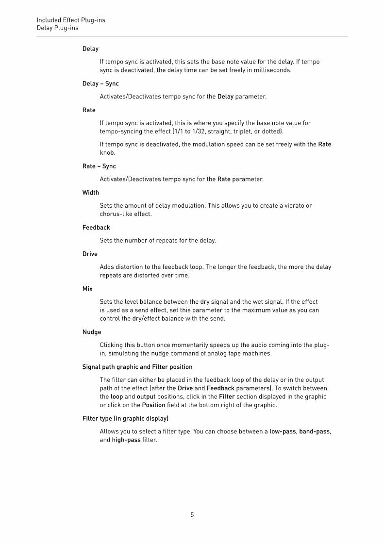
Signal path graphic and Filter position
The filter can either be placed in the feedback loop of the delay or in the outputpath of the effect (after the Drive and Feedback parameters). To switch betweenthe loop and output positions, click in the Filter section displayed in the graphicor click on the Position field at the bottom right of the graphic.
Filter type (in graphic display)
Allows you to select a filter type. You can choose between a low-pass, band-pass,and high-pass filter.
5
Included Effect Plug-insDelay Plug-ins
Filter Frequency LFO ModulationFreq
Sets the cutoff frequency for the filter. It is only available if tempo sync for theSpeed parameter is deactivated and the parameter is set to 0.
Speed
Sets the speed of the filter frequency LFO modulation. If tempo sync is activated,this parameter sets the base note value for synchronizing the modulation to thetempo of the host application.
If tempo sync is deactivated, the speed can be set freely with the Speed knob.
Speed – Sync
Activates/Deactivates tempo sync for the Speed parameter.
Range Lo/Hi
Set the range of the filter frequency modulation. Both positive (for example,Lo set to 50 and Hi set to 10000) and negative (for example, Lo set to 5000 andHi set to 500) ranges can be set. If tempo sync is off and Speed is set to zero,these parameters are inactive and the filter frequency is controlled by the Freqparameter instead.
Spatial
Introduces an offset between the channels to create a stereo panorama effectfor the filter frequency modulation. Turn clockwise for a more pronounced stereoeffect.
Filter Resonance LFO ModulationQ-Factor
Sets the resonance of the filter. It is only available if filter resonance LFOtempo sync is deactivated and the Speed parameter is set to 0. If tempo sync isactivated, the resonance is controlled by the Speed and Range parameters.
Speed
Sets the speed of the filter resonance LFO modulation. If tempo sync is activated,this parameter sets the base note value for tempo syncing the modulation.
If tempo sync is deactivated, the speed can be set freely with the Speed knob.
Speed – Sync
Activates/Deactivates tempo sync for the Speed parameter.
Range Lo/Hi
Set the range of the filter resonance modulation. Both positive (for example, Loset to 50 and Hi set to 100) and negative (for example, Lo set to 100 and Hi set to50) ranges can be set. If tempo sync is deactivated and Speed is set to zero, theseparameters are inactive and the filter resonance is controlled by the Q-Factorparameter instead.
6

Included Effect Plug-insDelay Plug-ins
Spatial
Introduces an offset between the channels to create a stereo panorama effect forthe filter resonance modulation. Turn clockwise for a more pronounced stereoeffect.
MonoDelayThis is a mono delay effect that can either be tempo-based or use freely specified delay timesettings.
CubaseLE
CubaseAI
CubaseElements
CubaseArtist
CubasePro
Nuendo NEK
Included with X X X X X X –
Side-chainsupport
– – – X X X –
Delay
If tempo sync is activated, this sets the base note value for the delay. If temposync is deactivated, the delay time can be set freely in milliseconds.
Sync
Activates/Deactivates tempo sync.
Feedback
Sets the number of repeats for the delay.
Filter Lo
Affects the feedback loop of the effect signal and allows you to roll off lowfrequencies. The button below the knob activates/deactivates the filter.
Filter Hi
Affects the feedback loop of the effect signal and allows you to roll off highfrequencies. The button below the knob activates/deactivates the filter.
Mix
Sets the level balance between the dry signal and the wet signal. If the effectis used as a send effect, set this parameter to the maximum value as you cancontrol the dry/effect balance with the send.
7

Included Effect Plug-insDelay Plug-ins
NOTE
If side-chaining is supported, the delay can also be controlled from another signal sourcevia the side-chain input. If the side-chain signal exceeds the threshold, the delay repeatsare silenced. If the signal drops below the threshold, the delay repeats reappear. For adescription of how to set up side-chain routing, see the Operation Manual.
PingPongDelayThis is a stereo delay effect that alternates each delay repeat between the left and rightchannels. The effect can either be tempo-based or use freely specified delay time settings.
CubaseLE
CubaseAI
CubaseElements
CubaseArtist
CubasePro
Nuendo NEK
Included with – – X X X X –
Side-chainsupport
– – – X X X –
NOTE
This plug-in works only on stereo tracks.
Delay
If tempo sync is activated, this sets the base note value for the delay. If temposync is deactivated, the delay time can be set freely in milliseconds.
Sync
Activates/Deactivates tempo sync.
Feedback
Sets the number of repeats for the delay.
Filter Lo
Affects the feedback loop of the effect signal and allows you to roll off lowfrequencies. The button below the knob activates/deactivates the filter.
Filter Hi
Affects the feedback loop of the effect signal and allows you to roll off highfrequencies. The button below the knob activates/deactivates the filter.
8

Included Effect Plug-insDelay Plug-ins
Spatial
Sets the stereo width for the left/right repeats. Turn clockwise for a morepronounced stereo ping-pong effect.
Mix
Sets the level balance between the dry signal and the wet signal. If the effectis used as a send effect, set this parameter to the maximum value as you cancontrol the dry/effect balance with the send.
NOTE
If side-chaining is supported, the delay can also be controlled from another signal sourcevia the side-chain input. If the side-chain signal exceeds the threshold, the delay repeatsare silenced. If the signal drops below the threshold, the delay repeats reappear. For adescription of how to set up side-chain routing, see the Operation Manual.
StereoDelayStereoDelay has two independent delay lines which either use tempo-based or freelyspecified delay time settings.
CubaseLE
CubaseAI
CubaseElements
CubaseArtist
CubasePro
Nuendo NEK
Included with – – – X X X –
Side-chainsupport
– – – X X X –
NOTE
This plug-in works only on stereo tracks.
Delay
If tempo sync is activated, this sets the base note value for the delay. If temposync is deactivated, the delay time can be set freely in milliseconds.
Sync
Activates/Deactivates tempo sync for the corresponding delay.
Feedback
Set the number of repeats for each delay.
9
Included Effect Plug-insDistortion Plug-ins
Filter Lo
Affects the feedback loop of the effect signal and allows you to roll off lowfrequencies. The button below the knob activates/deactivates the filter.
Filter Hi
Affects the feedback loop of the effect signal and allows you to roll off highfrequencies. The button below the knob activates/deactivates the filter.
Pan
Set the stereo position for each delay.
Mix
Sets the level balance between the dry signal and the wet signal. If the effectis used as a send effect, set this parameter to the maximum value as you cancontrol the dry/effect balance with the send.
NOTE
If side-chaining is supported, the delay can also be controlled from another signal sourcevia the side-chain input. If the side-chain signal exceeds the threshold, the delay repeatsare silenced. If the signal drops below the threshold, the delay repeats reappear. For adescription of how to set up side-chain routing, see the Operation Manual.
Distortion Plug-ins
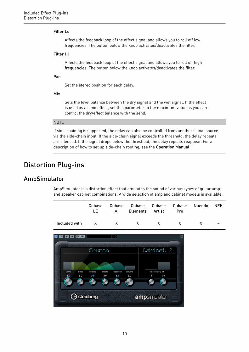
AmpSimulatorAmpSimulator is a distortion effect that emulates the sound of various types of guitar ampand speaker cabinet combinations. A wide selection of amp and cabinet models is available.
CubaseLE
CubaseAI
CubaseElements
CubaseArtist
CubasePro
Nuendo NEK
Included with X X X X X X –
10

Included Effect Plug-insDistortion Plug-ins
Amplifier pop-up menu
Click the amplifier name shown at the top of the amp section to open this pop-upmenu. It allows you to select an amplifier model. This section can be bypassed byselecting No Amp.
Drive
Controls the amount of amp overdrive.
Bass
Tone control for the low frequencies.
Middle
Tone control for the mid frequencies.
Treble
Tone control for the high frequencies.
Presence
Boosts or dampens the higher frequencies.
Volume
Controls the overall output level.
Cabinet pop-up menu
Click the cabinet name shown at the top of the cabinet section to open this pop-up menu. It allows you to select a speaker cabinet model. This section can bebypassed by selecting No Speaker.
Damping Lo/Hi
Further tone controls for shaping the sound of the selected speaker cabinet.Click the values, enter a new value and press Enter.
BitCrusherIf you are into lo-fi sound, BitCrusher is the effect for you. It offers the possibility ofdecimating and truncating the input audio signal by bit reduction, to get a noisy, distortedsound. For example, you can make a 24-bit audio signal sound like an 8 or 4-bit signal, oreven render it completely garbled and unrecognizable.
CubaseLE
CubaseAI
CubaseElements
CubaseArtist
CubasePro
Nuendo NEK
Included with X X X X X X –
11

Included Effect Plug-insDistortion Plug-ins
Mode
Allows you to select one of the four operating modes. In each mode, the plug-insounds differently. Modes I and III are nastier and noisier, while modes II and IVare more subtle.
Sample Divider
Sets the amount by which the audio samples are decimated. At the highestsetting, nearly all of the information describing the original audio signal iseliminated, turning the signal into unrecognizable noise.
Depth (0 to 24 bits)
Defines the bit resolution. A setting of 24 gives the highest audio quality, while asetting of 1 creates mostly noise.
Output
Sets the output level.
Mix
Sets the level balance between the dry signal and the wet signal.
DaTubeThis effect emulates the characteristic warm, lush sound of a tube amplifier.
CubaseLE
CubaseAI
CubaseElements
CubaseArtist
CubasePro
Nuendo NEK
Included with – X X X X X –
Drive
Sets the pre-gain of the amplifier. Use high values if you want an overdrivensound just on the verge of distortion.
12

Included Effect Plug-insDistortion Plug-ins
Balance
Sets the balance between the signal processed by the Drive parameter and thedry input signal. For maximum drive effect, set this to its highest value.
Output
Adjusts the post-gain, or output level, of the amplifier.
DistortionDistortion adds crunch to your tracks.
CubaseLE
CubaseAI
CubaseElements
CubaseArtist
CubasePro
Nuendo NEK
Included with X X X X X X –
Boost
Increases the distortion amount.
Feedback
Feeds part of the output signal back to the effect input. Higher settings increasethe distortion effect.
Tone
Lets you select a frequency range to which to apply the distortion effect.
Spatial
Changes the distortion characteristics of the left and right channels, thuscreating a stereo effect.
Output
Sets the output level.
GrungelizerGrungelizer adds noise and static to your recordings – like listening to a radio with badreception, or a worn and scratched vinyl record.
CubaseLE
CubaseAI
CubaseElements
CubaseArtist
CubasePro
Nuendo NEK
Included with X X X X X X –
13
Included Effect Plug-insDistortion Plug-ins
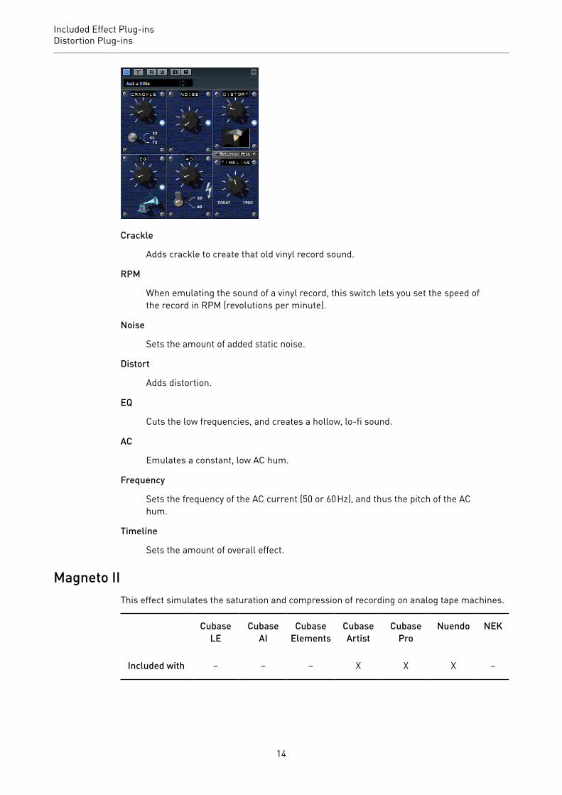
Crackle
Adds crackle to create that old vinyl record sound.
RPM
When emulating the sound of a vinyl record, this switch lets you set the speed ofthe record in RPM (revolutions per minute).
Noise
Sets the amount of added static noise.
Distort
Adds distortion.
EQ
Cuts the low frequencies, and creates a hollow, lo-fi sound.
AC
Emulates a constant, low AC hum.
Frequency
Sets the frequency of the AC current (50 or 60 Hz), and thus the pitch of the AChum.
Timeline
Sets the amount of overall effect.
Magneto IIThis effect simulates the saturation and compression of recording on analog tape machines.
CubaseLE
CubaseAI
CubaseElements
CubaseArtist
CubasePro
Nuendo NEK
Included with – – – X X X –
14

Included Effect Plug-insDistortion Plug-ins
Saturation
Determines the amount of saturation and the generation of overtones. This leadsto a small increase in input gain.
Saturation On/Off
Activates/Deactivates the saturation effect.
Dual Mode
Simulates the use of two machines.
Frequency Range Low/Hi
These parameters set the frequency range of the spectrum band to which thetape effect is applied.
For example, to avoid the saturation of lower frequencies, set the Freq Low valueto 200 Hz or 300 Hz. To avoid the saturation of very high frequencies, set the FreqHi parameter to values below 10 kHz.
Tape Solo
Allows you to hear only the set frequency range including the tape simulationeffect. This helps you to determine the appropriate frequency range.
HF-Adjust
Sets the amount of high frequency content of the saturated signal.
HF-Adjust On/Off
Activates/Deactivates the HF-Adjust filter.
VU Input/Output
The buttons determine whether the VU meter shows the level of the input or ofthe output signal. To set the input/output level, use the knob or enter a value inthe value field.
15

Included Effect Plug-insDistortion Plug-ins
Quadrafuzz v2Quadrafuzz v2 is a multi-band distortion and multi-effect plug-in for processing drums andloops but also for treatment of vocals, for example. You can distort up to 4 bands. 5 differentdistortion modes with several sub-modes are available.
CubaseLE
CubaseAI
CubaseElements
CubaseArtist
CubasePro
Nuendo NEK
Included with – – – X X X –
Frequency Band EditorThe frequency band editor in the upper half of the panel is where you set the width of thefrequency bands as well as the output level. The vertical value scale to the left shows thegain level of each frequency band. The horizontal scale shows the available frequency range.
• To define the frequency range of the different frequency bands, use the handles at thesides of each frequency band.
16

Included Effect Plug-insDistortion Plug-ins
• To attenuate or boost the output level of each frequency band by ±15 dB, use thehandles on top of each frequency band.
Global SettingsSB
Switches between multi band and single band mode.
Scenes
You can save up to 8 different settings. If the default setting of a scene is active,the selected scene button lights up yellow.
If you change the default settings, the button lights up green, indicating that thisscene has customized settings.
To copy the settings of a scene to another scene, select the scene that you wantto copy, click Copy, and click one of the numbered buttons.
You can automate the selection of scenes.
Mix
Sets the level balance between the dry signal and the wet signal.
Output (-24 to 24 dB)
Sets the output level.
Band SettingsMute
To mute each frequency band, activate the M button in each section.
Bypassing Frequency Bands
To bypass each frequency band, activate the Bypass Band button in eachsection.
Soloing Frequency Bands
To solo a frequency band, activate the S button in each section. Only one band canbe soloed at a time.
In/Out meter
Display the input and output level.
Gate
Determines the level at which the gate is activated. Signal levels above the setthreshold trigger the gate to open, and signal levels below the set threshold closethe gate.
17
Included Effect Plug-insDistortion Plug-ins
TapeThis band mode simulates the saturation and compression of recording on analog tapemachines.
Drive
Controls the amount of tape saturation.
Tape Mode Dual
Simulates the use of two machines.
TubeThis band mode simulates the saturation effects using analog tubes.
Drive
Controls the amount of tube saturation.
Tubes
Determine the number of tubes that are simulated.
DistThis band mode adds distortion to your tracks.
Drive
Controls the amount of distortion.
FBK
Feeds part of the output signal back to the effect input. Higher settings increasethe distortion effect.
AmpThis band mode simulates the sound of various types of guitar amps.
Drive
Controls the amount of amp overdrive.
Amp Types
You can select the following types of guitar amps:
• Amp Clean• Amp Crunch• Amp Lead
DecThis band mode allows you to decimate and truncate the input audio signal to create a noisy,distorted sound.
18
Included Effect Plug-insDistortion Plug-ins
Decimator
Controls the resulting bit-resolution. The lower the resolution, the higher thedistortion effect.
Mode
Allows you to select one of the four operating modes. In each mode, the plug-insounds differently. Modes I and III are nastier and noisier, while modes II and IVare more subtle.
S&H
Sets the amount by which the audio samples are decimated. At the highestsetting, nearly all of the information describing the original audio signal iseliminated, turning the signal into unrecognizable noise.
DelayTo open the Delay section, click the Delay button.
Time
If tempo sync is activated, this is where you specify the base note value fortempo-syncing the effect (1/1 to 1/32, straight, triplet, or dotted).
If tempo sync is deactivated, the delay time can be set freely with the Time knob.
Sync
Activates/Deactivates tempo sync for the corresponding delay.
Duck
Determines how much the delay signal ducks when an audio signal is present.
Mix
Sets the level balance between the dry signal and the wet signal.
FBK
Determines the number of repeats for each delay.
Mode
If this option is activated, the delay signal is routed back into the distortion unit tocreate a feedback with distortion.
NOTE
High FBK values and low Duck values in combination with activated Mode can lead tounwanted noise.
SliderWidth
Sets the stereo width for the corresponding band.
19

Included Effect Plug-insDistortion Plug-ins
Out
Sets the output gain for the corresponding band.
Pan
Sets the stereo position for the corresponding band.
Mix
Sets the level balance between the dry signal and the wet signal.
SoftClipperThis effect adds soft overdrive, with independent control over the second and third harmonic.
CubaseLE
CubaseAI
CubaseElements
CubaseArtist
CubasePro
Nuendo NEK
Included with – – – – X X –
Input (-12 to 24 dB)
Sets the pre-gain. Use high values if you want an overdriven sound just on theverge of distortion.
Mix
Sets the level balance between the dry signal and the wet signal.
Output
Sets the output level.
VST Amp RackVST Amp Rack is a powerful guitar amp simulator. It offers a choice of amplifiers andspeaker cabinets that can be combined with stomp box effects.
CubaseLE
CubaseAI
CubaseElements
CubaseArtist
CubasePro
Nuendo NEK
Included with – – X X X X –
20
Included Effect Plug-insDistortion Plug-ins
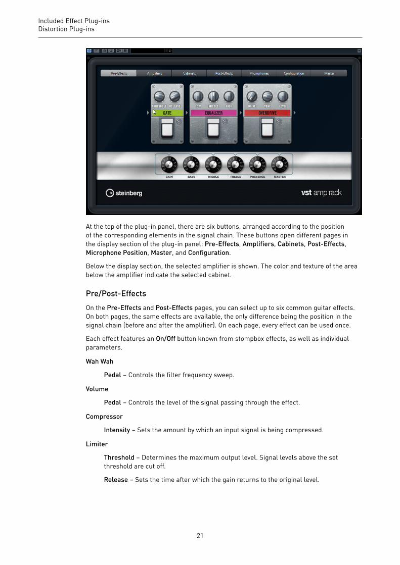
At the top of the plug-in panel, there are six buttons, arranged according to the positionof the corresponding elements in the signal chain. These buttons open different pages inthe display section of the plug-in panel: Pre-Effects, Amplifiers, Cabinets, Post-Effects,Microphone Position, Master, and Configuration.
Below the display section, the selected amplifier is shown. The color and texture of the areabelow the amplifier indicate the selected cabinet.
Pre/Post-EffectsOn the Pre-Effects and Post-Effects pages, you can select up to six common guitar effects.On both pages, the same effects are available, the only difference being the position in thesignal chain (before and after the amplifier). On each page, every effect can be used once.
Each effect features an On/Off button known from stompbox effects, as well as individualparameters.
Wah Wah
Pedal – Controls the filter frequency sweep.
Volume
Pedal – Controls the level of the signal passing through the effect.
Compressor
Intensity – Sets the amount by which an input signal is being compressed.
Limiter
Threshold – Determines the maximum output level. Signal levels above the setthreshold are cut off.
Release – Sets the time after which the gain returns to the original level.
21

Included Effect Plug-insDistortion Plug-ins
Maximizer
Amount – Determines the loudness of the signal.
Chorus
Rate – Allows you to set the sweep rate. This parameter can be synchronized tothe project tempo.
Width – Determines the depth of the chorus effect. Higher settings produce amore pronounced effect.
Phaser
Rate – Allows you to set the sweep rate. This parameter can be synchronized tothe project tempo.
Width – Determines the width of the modulation effect between higher and lowerfrequencies.
Flanger
Rate – Allows you to set the sweep rate. This parameter can be synchronized tothe project tempo.
Feedback – Determines the character of the flanger effect. Higher settingsproduce a more metallic sounding sweep.
Mix – Sets the level balance between the dry signal and the wet signal.
Tremolo
Rate – Allows you to set the modulation speed. This parameter can besynchronized to the project tempo.
Depth – Governs the depth of the amplitude modulation.
Octaver
Direct – Adjusts the mix of the original signal and the generated voices. A valueof 0 means only the generated and transposed signal is heard. By raising thisvalue, more of the original signal is heard.
Octave 1 – Adjusts the level of the signal that is generated one octave below theoriginal pitch. A setting of 0 means that the voice is muted.
Octave 2 – Adjusts the level of the signal that is generated two octaves below theoriginal pitch. A setting of 0 means that the voice is muted.
Delay
Delay – Sets the delay time in milliseconds. This parameter can be synchronizedto the project tempo.
Feedback – Sets the number of repeats for the delay.
Mix – Sets the level balance between the dry signal and the wet signal.
22

Included Effect Plug-insDistortion Plug-ins
Tape Delay
Delay – Tape Delay creates a delay effect known from tape machines. TheDelay parameter sets the delay time in milliseconds. This parameter can besynchronized to the project tempo.
Feedback – Sets the number of repeats for the delay.
Mix – Sets the level balance between the dry signal and the wet signal.
Tape Ducking Delay
Delay – Tape Ducking Delay creates a delay effect known from tape machineswith a ducking parameter. The Delay parameter sets the delay time inmilliseconds. This parameter can be synchronized to the project tempo.
Feedback – Sets the number of repeats for the delay.
Duck – Works like an automatic mix parameter. If the level of the input signalis high, the portion of the effect signal is lowered, or ducked (low internal mixvalue). If the level of the input signal is low, the portion of the effect signal israised (high internal mix value). This way the delayed signal stays rather dryduring loud or intensely played passages.
Overdrive
Drive – Overdrive creates a tube-like overdrive effect. The higher this value, themore harmonics are added to the output signal of this effect.
Tone – Works as a filter effect on the added harmonics.
Level – Adjusts the output level.
Fuzz
Boost – Fuzz creates a rather harsh distortion effect. The higher this value, themore distortion is created.
Tone – Works as a filter effect on the added harmonics.
Level – Adjusts the output level.
Gate
Threshold – Determines the level at which the gate is activated. Signal levelsabove the set threshold trigger the gate to open, and signal levels below the setthreshold close the gate.
Release – Sets the time after which the gate closes.
Equalizer
Low – Changes the level of the low-frequency portion of the incoming signal.
Middle – Changes the level of the mid-frequency portion of the incoming signal.
High – Changes the level of the high-frequency portion of the incoming signal.
Reverb
Type – A convolution-based reverb effect. This parameter allows you to switchbetween different reverb types (Studio, Hall, Plate, and Room).
Mix – Sets the level balance between the dry signal and the wet signal.
23

Included Effect Plug-insDistortion Plug-ins
Sync ModeSome parameters can be synchronized to the tempo of the host application.
The names of these parameters are underlined. Click a knob to activate or deactivate temposync. An LED at the top right of the knob indicates that sync mode is active. You can thenselect a base note value for tempo syncing from the pop-up menu above the control.
Using Effects• To insert a new effect, click the + button that appears if you point the mouse at an
empty plug-in slot or at one of the arrows before or after a used effect slot.• To remove an effect from an effect slot, click the effect name and select None from the
pop-up menu.• To change the order of the effects in the chain, click on an effect and drag it to another
position.• To activate or deactivate an effect, click the pedal-like button below the effect name. If
an effect is active, the LED next to the button is lit.
NOTE
• Pre-effects and post-effects can be mono or stereo, depending on the trackconfiguration.
• Using quick controls you can set up an external MIDI device, such as a foot controller,to control the VST Amp Rack effects. For more information about quick controls, seethe Operation Manual.
AmplifiersThe amps available on the Amplifiers page are modeled on real-life amplifiers. Each ampfeatures settings typical for guitar recording, such as gain, equalizers, and master volume.The sound-related parameters Bass, Middle, Treble, and Presence have a significant impacton the overall character and sound of the corresponding amp.
Plexi
Classic British rock tone; extremely transparent sound, very responsive.
Plexi Lead
British rock tone of the 70s and 80s.
Diamond
The cutting edge hard rock and metal sounds of the 90s.
24

Included Effect Plug-insDistortion Plug-ins
Blackface
Classic American clean tone.
Tweed
Clean and crunchy tones; originally developed as a bass amp.
Deluxe
American crunch sound coming from a rather small amp with a big tone.
British Custom
Produces the sparkling clean or harmonically distorted rhythm sounds of the60s.
The different amps keep their settings if you switch models. However, if you want to use thesame settings after reloading the plug-in, you need to set up a preset.
Selecting and Deactivating Amplifiers
To switch amps on the Amplifiers page, click the model that you want to use. Select NoAmplifier if you only want to use the cabinets and effects.
CabinetsThe cabinets available on the Cabinets page simulate real-life combo boxes or speakers.For each amp, a corresponding cabinet type is available, but you can also combine differentamps and cabinets.
Selecting and Deactivating Cabinets
• To switch cabinets on the Cabinets page, click the model that you want to use. SelectNo Cabinet if you only want to use the amps and effects.
• If you select Link Amplifier & Cabinet Choice, the plug-in automatically selects thecabinet corresponding to the selected amp model.
MicrophonesOn the Microphones page, you can choose between different microphone positions. Thesepositions result from two different angles (center and edge) and three different distancesfrom the speaker, as well as an additional center position at an even greater distance fromthe speaker.
You can choose between two microphone types: a large-diaphragm condenser microphoneand a dynamic microphone. You can crossfade between the characteristics of the twomicrophones.
• To select one of the microphone types or blend between the two types, turn the Mixcontrol between the two microphones.
Placing the Microphone
• To select a microphone position, click the corresponding ball in the graphic. Theselected position is marked in red.
MasterUse the Master page to fine-tune the sound.
25

Included Effect Plug-insDistortion Plug-ins
Input/Output Level Meters
The input and output level meters on the left and the right of the Master section show thesignal level of your audio. The rectangle on the input meter indicates the optimum incominglevel range. In compact view, the input and output levels are indicated by two LEDs at the topleft and right.
Using the Master Controls
• To activate/deactivate the equalizer, click the pedal-like On/Off button. If the equalizeris active, the LED next to the button is lit.
• To activate/deactivate an equalizer band, click the corresponding Gain knob. If a bandis active, the LED to the left of the Gain knob is lit.
• To tune your guitar strings, click the pedal-like On/Off button to activate the Tunerand play a string. If the correct pitch is displayed and the row of LEDs below the digitaldisplay is green, the string is tuned correctly.If the pitch is too low, red LEDs are lit on the left. If the pitch is too high, red LEDs arelit on the right. The more LEDs are lit, the lower/higher is the pitch.
• To mute the output signal of the plug-in, click the pedal-like Master button. If theoutput is muted, the LED is not lit. Use this to tune your guitar in silence, for example.
• To change the volume of the output signal, use the Level control on the Master page.
ConfigurationOn the Configuration page, you can specify whether you want to use VST Amp Rack in stereoor in mono mode.
• To process the pre-effects, the amplifier, and the cabinets in full stereo mode, makesure that the plug-in is inserted on a stereo track, and activate the Stereo button.
• To use the effect in mono-mode, make sure that the plug-in is inserted on a monotrack, and activate the Mono button.
NOTE
In stereo mode, the effect requires more processing power.
View SettingsYou can choose between 2 views: the default view and a compact view, which takes up lessscreen space.
In the default view, you can use the buttons at the top of the plug-in panel to open thecorresponding page in the display section above the amp controls. You can horizontally resizethe plug-in panel by clicking and dragging the edges or corners.
In the compact view, the display section is hidden from view. You can change the ampsettings and switch amps or cabinets using the mouse wheel.
Using the Smart Controls
Smart controls become visible on the plug-in frame when you move the mouse pointer overon the plug-in panel.
Switching between Default and Compact View
26

Included Effect Plug-insDistortion Plug-ins
• To toggle between the different views, click the down/up arrow button (Show/HideExtended Display) at the top center of the plug-in frame.
Changing the Amplifier and Cabinet Selection in the Compact View
In the compact view, a smart control on the lower border of the plug-in frame allows you toselect different amplifier and cabinet models.
• To select a different amplifier or cabinet, click the name and select a different modelfrom the pop-up menu.
• To lock the amplifier and cabinet combination, activate the Link/Unlink Amplifier &Cabinet Choice button. If you now select another amp model, the cabinet selectionfollows. However, if you select a different cabinet model, the lock is deactivated.
Previewing Effect Settings
In both views, you can show a preview of the pre- and post-effects that you selected on thecorresponding pages:
• Click and hold the Show Pre-Effects or Show Post-Effects button at the bottom left orright of the plug-in frame.
VST Bass AmpVST Bass Amp is a bass amp simulator. It offers a choice of amplifiers and speaker cabinetsthat can be combined with stomp box effects.
CubaseLE
CubaseAI
CubaseElements
CubaseArtist
CubasePro
Nuendo NEK
Included with – – – X X X –
27

Included Effect Plug-insDistortion Plug-ins
At the top of the plug-in panel, the following buttons open different pages in the displaysection of the plug-in panel: Pre-Effects, Amplifiers, Cabinets, Post-Effects, Microphones,Configuration, and Master.
These buttons are arranged according to the position of the corresponding elements in thesignal chain.
Below the display section, the selected bass amplifier is displayed. The color and texture ofthe area below the bass amp indicate the selected cabinet.
Pre/Post-EffectsOn the Pre-Effects and Post-Effects pages, you can select up to six common bass effects. Onboth pages, the same effects are available, the only difference being the position in the signalchain (before or after the bass amplifier). On each page, every effect can be used once.
Each effect features an On/Off button known from stompbox effects, as well as individualparameters.
Wah Wah
Pedal – Controls the filter frequency sweep.
Envelope Filter
Range – Determines the frequency range.
Q-Factor – Sets the intensity of the envelope filter effect.
Sensitivity – Determines how sensitive the effect reacts to the instrument level.
Attack – Determines how quickly an effect reacts to the input signal.
Mix – Sets the level balance between the dry signal and the wet signal.
Type – Sets the filter type.
Release – Determines how quickly the effect fades after the input signal stops.
28
Included Effect Plug-insDistortion Plug-ins
Volume
Pedal – Controls the level of the signal passing through the effect.
Compressor
Intensity – Sets the amount by which an input signal is being compressed.
Compressor MB
Lo Intensity – Sets the compressor effect in the low frequency band. Activate/deactivate Auto Makeup Mode by clicking the LED at the top right of the knob.
Hi Intensity – Sets the compressor effect in the high frequency band. Activate/deactivate Auto Makeup Mode by clicking the LED at the top right of the knob.
Crossover – Determines the crossover frequency between the low frequencyband and the high frequency band.
Output – Sets the output level.
Limiter
Threshold – Determines the maximum output level. Signal levels above the setthreshold are cut off.
Release – Sets the time after which the gain returns to the original level.
Maximizer
Amount – Determines the loudness of the signal.
Chorus
Rate – Allows you to set the sweep rate. This parameter can be synchronized tothe project tempo.
Width – Determines the depth of the chorus effect. Higher settings produce amore pronounced effect.
Tone – Allows you to attenuate low frequencies.
Mix – Sets the level balance between the dry signal and the wet signal.
Phaser
Rate – Allows you to set the sweep rate. This parameter can be synchronized tothe project tempo.
Width – Determines the width of the modulation effect between higher and lowerfrequencies.
Tone – Allows you to attenuate the low frequencies.
Mix – Sets the level balance between the dry signal and the wet signal.
Flanger
Rate – Allows you to set the sweep rate. This parameter can be synchronized tothe project tempo.
Feedback – Determines the character of the flanger effect. Higher settingsproduce a more metallic sounding sweep.
29

Included Effect Plug-insDistortion Plug-ins
Tone – Allows you to attenuate the low frequencies.
Mix – Sets the level balance between the dry signal and the wet signal.
DI Driver
Level – Sets the output level.
Blend – Blends between normal and tube emulation circuitry. With Blend at 0,Drive and Presence are not active.
Bass – Boosts or attenuates low frequencies.
Treble – Boosts or attenuates high frequencies.
Presence – Boosts or attenuates upper harmonics and attacks.
Drive – Sets gain and overdrive.
Enhancer
Enhance – Simulates the classic enhancer effect.
Tone – Allows you to attenuate low frequencies.
Octaver
Direct – Adjusts the level of the original signal. A value of 0 means only thegenerated and transposed signal is heard. By raising this value, more of theoriginal signal is heard.
Octave 1 – Adjusts the level of the signal that is generated one octave below theoriginal pitch. A setting of 0 means that the voice is muted.
Tone – Changes the sound character of the generated signal.
Delay
Delay – Sets the delay time in milliseconds. This parameter can be synchronizedto the project tempo.
Feedback – The higher this setting, the more delay repeats are created.
Mix – Sets the level balance between the dry signal and the wet signal.
Tape Ducking Delay
Delay – The Delay parameter sets the delay time in milliseconds.
Feedback – The higher this setting, the more delay repeats are created.
Duck – Works like an automatic mix parameter. If the level of the input signalis high, the portion of the effect signal is lowered, or ducked (low internal mixvalue). If the level of the input signal is low, the portion of the effect signal israised (high internal mix value). This way the delayed signal stays rather dryduring loud or intensely played passages.
Tone – Allows you to attenuate the low frequencies.
Mix – Sets the level balance between the dry signal and the wet signal.
30

Included Effect Plug-insDistortion Plug-ins
Overdrive
Drive – Overdrive creates a tube-like overdrive effect. The higher this value, themore harmonics are added to the output signal of this effect.
Tone – Works as a filter effect on the added harmonics.
Level – Adjusts the output level.
Magneto II
Drive – Controls the amount of tape saturation.
Low/High – These parameters set the frequency range of the spectrum band towhich the tape effect is applied.
HF-Adjust – Sets the amount of high frequency content of the saturated signal.
Gate
Threshold – Determines the level at which the gate is activated. Signal levelsabove the set threshold open the gate and signal levels below the set thresholdclose the gate.
Release – Sets the time after which the gate closes.
Equalizer
Low – Changes the level of the low-frequency portion of the incoming signal.
Middle – Changes the level of the mid-frequency portion of the incoming signal.
High – Changes the level of the high-frequency portion of the incoming signal.
Graphical EQ
Display – Consists of 8 sliders that set the level of each frequency band. Allowsyou to draw response curves by clicking and dragging with the mouse.
Reset Sliders – At the lower right of the Display. Flattens all values to 0 dB.
Output Slider – Allows you to control the frequency response.
Reverb
Type – A convolution-based reverb effect. This parameter allows you to switchbetween the reverb types Studio, Hall, Plate, and Room.
Mix – Sets the level balance between the dry signal and the wet signal.
SyncSome parameters can be synchronized to the tempo of the host application.
The names of these parameters are underlined. Click a knob to activate or deactivate temposync. An LED at the top right of the knob indicates that sync mode is active. You can thenselect a base note value for tempo syncing from the pop-up menu above the control.
31

Included Effect Plug-insDistortion Plug-ins
Using Effects• To insert a new effect, click the + button that appears if you point the mouse at an
empty plug-in slot or at one of the arrows before or after a used effect slot.• To remove an effect from an effect slot, click the effect name and select None from the
pop-up menu.• To change the order of the effects in the chain, click on an effect and drag it to another
position.• To activate or deactivate an effect, click the pedal-like button below the effect name. If
an effect is active, the LED next to the button is lit.
NOTE
• Pre-effects and post-effects can be mono or stereo, depending on the trackconfiguration.
• Using quick controls you can set up an external MIDI device, such as a foot controller,to control the VST Bass Amp effects. For more information about quick controls, seethe Operation Manual.
AmplifiersThe amps available on the Amplifiers page are modeled on real-life amplifiers. Each ampfeatures settings typical for bass recording, such as gain, equalizers, and master volume.The sound-related parameters bass, low mid, high mid, and treble have a significant impacton the overall character and sound of the corresponding amp. Shape 1 and Shape 2 offerpredefined tone shaping.
ValveAmp300
A famous tube amplifier from the 70s, useful for rock playing styles.
Greyhound
An amplifier, well known for its typical growl, useful for several playing styles.
GreenT
A classic amplifier from the 80s, useful for funk and rock playing styles.
Paradise
An amplifier from the 90s, with a hifi-like clear tone, that makes it applicable forseveral styles.
32
Included Effect Plug-insDistortion Plug-ins
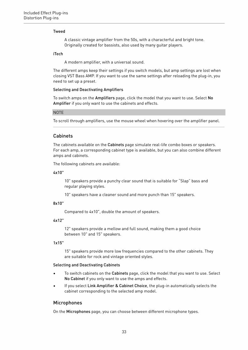
Tweed
A classic vintage amplifier from the 50s, with a characterful and bright tone.Originally created for bassists, also used by many guitar players.
iTech
A modern amplifier, with a universal sound.
The different amps keep their settings if you switch models, but amp settings are lost whenclosing VST Bass AMP. If you want to use the same settings after reloading the plug-in, youneed to set up a preset.
Selecting and Deactivating Amplifiers
To switch amps on the Amplifiers page, click the model that you want to use. Select NoAmplifier if you only want to use the cabinets and effects.
NOTE
To scroll through amplifiers, use the mouse wheel when hovering over the amplifier panel.
CabinetsThe cabinets available on the Cabinets page simulate real-life combo boxes or speakers.For each amp, a corresponding cabinet type is available, but you can also combine differentamps and cabinets.
The following cabinets are available:
4x10"
10" speakers provide a punchy clear sound that is suitable for “Slap” bass andregular playing styles.
10" speakers have a cleaner sound and more punch than 15" speakers.
8x10"
Compared to 4x10", double the amount of speakers.
4x12"
12" speakers provide a mellow and full sound, making them a good choicebetween 10" and 15" speakers.
1x15"
15" speakers provide more low frequencies compared to the other cabinets. Theyare suitable for rock and vintage oriented styles.
Selecting and Deactivating Cabinets
• To switch cabinets on the Cabinets page, click the model that you want to use. SelectNo Cabinet if you only want to use the amps and effects.
• If you select Link Amplifier & Cabinet Choice, the plug-in automatically selects thecabinet corresponding to the selected amp model.
MicrophonesOn the Microphones page, you can choose between different microphone types.
33

Included Effect Plug-insDistortion Plug-ins
57
Dynamic microphone with cardioid pickup pattern.
121
Ribbon microphone with figure-8 pattern.
409
Dynamic microphone with supercardioid pickup pattern.
421
Dynamic microphone with cardioid polar pattern.
545
Dynamic microphone with cardioid pattern that minimizes feedback.
5
Dynamic microphone with cardioid pickup pattern.
30
Reference and measurement microphone with omni directional polar pattern.
87
Condenser microphone with omni directional pattern.
You can choose between different microphone positions. These positions result from twodifferent angles (on axis and off axis) and three different distances from the cabinet.
You can crossfade between the characteristics of the two microphones.
• To select one of the microphone types or blend between the two types, turn the Mixcontrol between the two microphones.
• To select a microphone position, click the corresponding ball in front of the cabinet.The selected position is marked in red.
• To determine the ratio between line and mic, turn the Mix control on the left of thecabinet.
NOTE
To scroll through microphones, use the mouse wheel when hovering over a microphone.
MasterUse the Master page to fine-tune the sound.
Input/Output Level Meters
The input and output level meters on the left and the right of the Master sectionshow the signal level of your audio. The rectangle on the input meter indicatesthe optimum incoming level range. In all other views, the input and output levelsare indicated by two LEDs at the top left and right.
Using the Master Controls
34
Included Effect Plug-insDistortion Plug-ins
• To activate/deactivate the equalizer, click the pedal-like On/Off button. If the equalizeris active, the LED next to the button is lit.
• To activate/deactivate an equalizer band, click the corresponding Gain knob. If a bandis active, the LED to the left of the Gain knob is lit.
• To tune your guitar strings, click the pedal-like On/Off button to activate Tuner andplay a string. If the correct pitch is displayed and the row of LEDs below the digitaldisplay is green, the string is tuned correctly.If the pitch is too low, red LEDs are lit on the left. If the pitch is too high, red LEDs arelit on the right. The more LEDs are lit, the lower/higher is the pitch.
• To mute the output signal of the plug-in, click the pedal-like Master button. If theoutput is muted, the LED is not lit. Use this to tune your guitar in silence, for example.
• To change the volume of the output signal, use the Level control on the Master page.• NOTE
Master EQ functions only when a cabinet is selected.
ConfigurationOn the Configuration page, you can specify whether you want to use VST Bass Amp in stereoor in mono mode.
• To process the pre-effects, the amplifier, and the cabinets in full stereo mode, makesure that the plug-in is inserted on a stereo track, and activate the Stereo button.
• To use the effect in mono-mode, make sure that the plug-in is inserted on a monotrack, and activate the Mono button.
NOTE
In stereo mode, the effect requires more processing power. Use mono configuration on astereo track to save processing power.
View SettingsYou can choose between 2 views: the default view and a compact view, which takes up lessscreen space.
In the default view, you can use the buttons at the top of the plug-in panel to open thecorresponding page in the display section above the amp controls. You can horizontally resizethe plug-in panel by clicking and dragging the edges or corners.
In the compact view, the display section is hidden from view. You can change the ampsettings and switch amps or cabinets using the mouse wheel.
Using the Smart Controls
Smart controls become visible on the plug-in frame when you move the mouse pointer overthe plug-in panel.
Switching between Default and Compact View
• To toggle between the different views, click the down/up arrow button (Show/HideExtended Display) at the top center of the plug-in frame.
35

Included Effect Plug-insDynamics Plug-ins
Changing the Amplifier and Cabinet Selection in the Compact View
In the compact view, a smart control on the lower border of the plug-in frame allows you toselect different amplifier and cabinet models.
• To select a different amplifier or cabinet, click the name and select a different modelfrom the pop-up menu.
• To lock the amplifier and cabinet combination, activate the Link/Unlink Amplifier &Cabinet Choice button. If you now select another amp model, the cabinet selectionfollows. However, if you select a different cabinet model, the lock is deactivated.
Previewing Effect Settings
In both views, you can show a preview of the pre- and post-effects that you selected on thecorresponding pages:
• Click and hold the Show Pre-Effects or Show Post-Effects button at the bottom left orright of the plug-in frame.
RELATED LINKSTuner on page 155
Dynamics Plug-ins
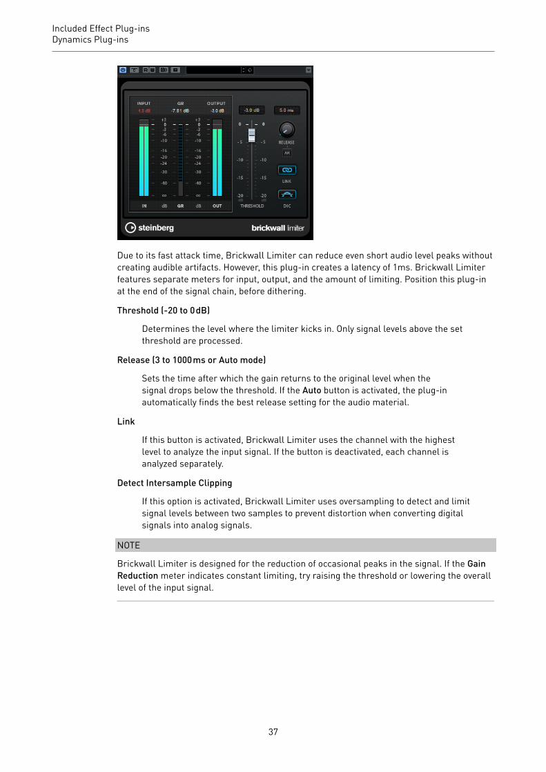
Brickwall LimiterBrickwall Limiter ensures that the output level never exceeds a set limit.
CubaseLE
CubaseAI
CubaseElements
CubaseArtist
CubasePro
Nuendo NEK
Included with – – X X X X –
36
Included Effect Plug-insDynamics Plug-ins
Due to its fast attack time, Brickwall Limiter can reduce even short audio level peaks withoutcreating audible artifacts. However, this plug-in creates a latency of 1ms. Brickwall Limiterfeatures separate meters for input, output, and the amount of limiting. Position this plug-inat the end of the signal chain, before dithering.
Threshold (-20 to 0 dB)
Determines the level where the limiter kicks in. Only signal levels above the setthreshold are processed.
Release (3 to 1000 ms or Auto mode)
Sets the time after which the gain returns to the original level when thesignal drops below the threshold. If the Auto button is activated, the plug-inautomatically finds the best release setting for the audio material.
Link
If this button is activated, Brickwall Limiter uses the channel with the highestlevel to analyze the input signal. If the button is deactivated, each channel isanalyzed separately.
Detect Intersample Clipping
If this option is activated, Brickwall Limiter uses oversampling to detect and limitsignal levels between two samples to prevent distortion when converting digitalsignals into analog signals.
NOTE
Brickwall Limiter is designed for the reduction of occasional peaks in the signal. If the GainReduction meter indicates constant limiting, try raising the threshold or lowering the overalllevel of the input signal.
37
Included Effect Plug-insDynamics Plug-ins
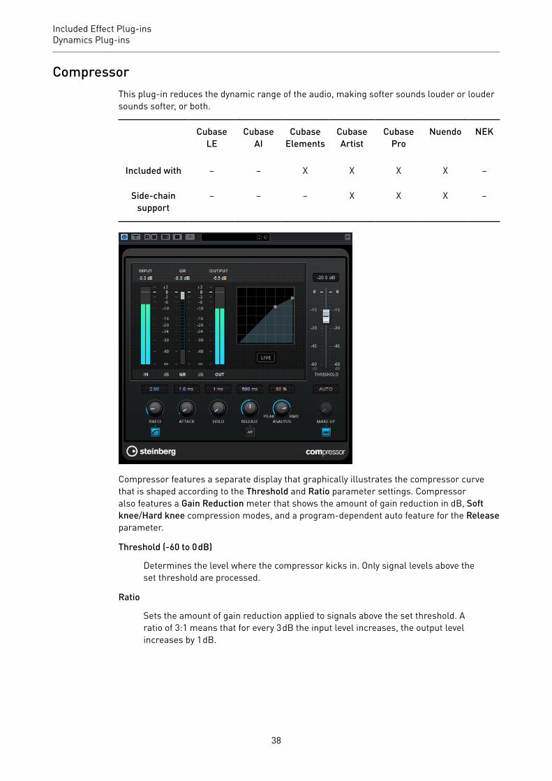
CompressorThis plug-in reduces the dynamic range of the audio, making softer sounds louder or loudersounds softer, or both.
CubaseLE
CubaseAI
CubaseElements
CubaseArtist
CubasePro
Nuendo NEK
Included with – – X X X X –
Side-chainsupport
– – – X X X –
Compressor features a separate display that graphically illustrates the compressor curvethat is shaped according to the Threshold and Ratio parameter settings. Compressoralso features a Gain Reduction meter that shows the amount of gain reduction in dB, Softknee/Hard knee compression modes, and a program-dependent auto feature for the Releaseparameter.
Threshold (-60 to 0 dB)
Determines the level where the compressor kicks in. Only signal levels above theset threshold are processed.
Ratio
Sets the amount of gain reduction applied to signals above the set threshold. Aratio of 3:1 means that for every 3 dB the input level increases, the output levelincreases by 1 dB.
38

Included Effect Plug-insDynamics Plug-ins
Soft Knee
If this button is deactivated, signals above the threshold are compressed instantlyaccording to the set ratio (hard knee). If Soft Knee is activated, the onset ofcompression is more gradual, producing a less drastic result.
Make-Up (0 to 24 dB or Auto mode)
Compensates for output gain loss, caused by compression. If the Auto button isactivated, the knob becomes dark and the output is automatically adjusted forgain loss.
Attack (0.1 to 100 ms)
Determines how fast the compressor responds to signals above the setthreshold. If the attack time is long, more of the early part of the signal passesthrough unprocessed.
Hold (0 to 5000 ms)
Sets the time the applied compression affects the signal after exceeding thethreshold. Short hold times are useful for DJ-style ducking, while longerhold times are required for music ducking, for example, when working on adocumentary film.
Release (10 to 1000 ms or Auto mode)
Sets the time after which the gain returns to its original level when thesignal drops below the threshold. If the Auto button is activated, the plug-inautomatically finds the best release setting for the audio material.
Analysis (Pure Peak to Pure RMS)
Determines whether the input signal is analyzed according to peak or RMSvalues, or a mixture of both. A value of 0 is pure peak and 100 pure RMS. RMSmode operates using the average power of the audio signal as a basis, whereasPeak mode operates more on peak levels. As a general guideline, RMS modeworks better on material with few transients such as vocals, and Peak modeworks better for percussive material with a lot of transient peaks.
Live
If this button is activated, the look-ahead feature of the effect is deactivated.Look-ahead produces more accurate processing, but adds a specific amountof latency as a trade-off. If Live mode is activated, there is no latency, which isbetter for live processing.
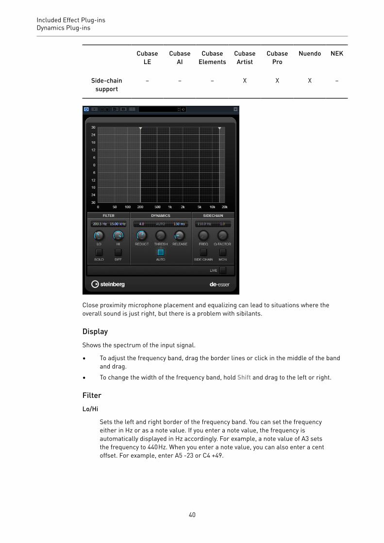
DeEsserThis effect reduces excessive sibilance, primarily for vocal recordings. It is a special type ofcompressor that is tuned to be sensitive to the frequencies produced by the s-sound.
CubaseLE
CubaseAI
CubaseElements
CubaseArtist
CubasePro
Nuendo NEK
Included with – – – X X X –
39
Included Effect Plug-insDynamics Plug-ins
CubaseLE
CubaseAI
CubaseElements
CubaseArtist
CubasePro
Nuendo NEK
Side-chainsupport
– – – X X X –
Close proximity microphone placement and equalizing can lead to situations where theoverall sound is just right, but there is a problem with sibilants.
DisplayShows the spectrum of the input signal.
• To adjust the frequency band, drag the border lines or click in the middle of the bandand drag.
• To change the width of the frequency band, hold Shift and drag to the left or right.
FilterLo/Hi
Sets the left and right border of the frequency band. You can set the frequencyeither in Hz or as a note value. If you enter a note value, the frequency isautomatically displayed in Hz accordingly. For example, a note value of A3 setsthe frequency to 440 Hz. When you enter a note value, you can also enter a centoffset. For example, enter A5 -23 or C4 +49.
40
Included Effect Plug-insDynamics Plug-ins
NOTE
Make sure that you enter a space between the note and the cent offset. Only inthis case, the cent offsets are taken into account.
Solo
Solos the frequency band. This helps you to find the appropriate position andwidth of that band.
Diff
Plays back what DeEsser removed from the signal. This help you to adjust thefrequency band, threshold, and reduction parameters, so that only sharp s-sounds are removed, for example.
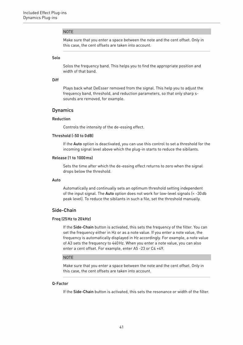
DynamicsReduction
Controls the intensity of the de-essing effect.
Threshold (-50 to 0 dB)
If the Auto option is deactivated, you can use this control to set a threshold for theincoming signal level above which the plug-in starts to reduce the sibilants.
Release (1 to 1000 ms)
Sets the time after which the de-essing effect returns to zero when the signaldrops below the threshold.
Auto
Automatically and continually sets an optimum threshold setting independentof the input signal. The Auto option does not work for low-level signals (< -30 dbpeak level). To reduce the sibilants in such a file, set the threshold manually.
Side-ChainFreq (25 Hz to 20 kHz)
If the Side-Chain button is activated, this sets the frequency of the filter. You canset the frequency either in Hz or as a note value. If you enter a note value, thefrequency is automatically displayed in Hz accordingly. For example, a note valueof A3 sets the frequency to 440 Hz. When you enter a note value, you can alsoenter a cent offset. For example, enter A5 -23 or C4 +49.
NOTE
Make sure that you enter a space between the note and the cent offset. Only inthis case, the cent offsets are taken into account.
Q-Factor
If the Side-Chain button is activated, this sets the resonance or width of the filter.
41

Included Effect Plug-insDynamics Plug-ins
Side
Activates the internal side-chain filter. You can now shape the input signalaccording to the filter parameters. Internal side-chaining can be useful fortailoring how the gate operates.
Monitor
Allows you to monitor the filtered signal.
Live
If this button is activated, the look-ahead feature of the effect is deactivated.Look-ahead produces more accurate processing, but adds a specific amountof latency as a trade-off. If Live mode is activated, there is no latency, which isbetter for live processing.
Positioning the DeEsser in the Signal ChainWhen recording a voice, the DeEsser’s position in the signal chain is usually located after themicrophone pre-amp and before a compressor/limiter. This keeps the compressor/limiterfrom unnecessarily limiting the overall signal dynamics.
EnvelopeShaperThis plug-in can be used to attenuate or boost the gain of the attack and release phase ofaudio material.
CubaseLE
CubaseAI
CubaseElements
CubaseArtist
CubasePro
Nuendo NEK
Included with – – X X X X –
Side-chainsupport
– – – X X X –
You can use the knobs or drag the breakpoints in the graphical display to change parametervalues. Be careful with levels when boosting the gain and if needed reduce the output level toavoid clipping.
42

Included Effect Plug-insDynamics Plug-ins
Attack (-20 to 20 dB)
Sets the gain of the attack phase of the signal.
Length (5 to 200 ms)
Sets the length of the attack phase.
Release (-20 to 20 dB)
Sets the gain of the release phase of the signal.
Output
Sets the output level.
NOTE
If side-chaining is supported, the effect can also be controlled from another signal source viathe side-chain input. If the side-chain signal exceeds the threshold, the effect is triggered.For a description of how to set up side-chain routing, see the Operation Manual.
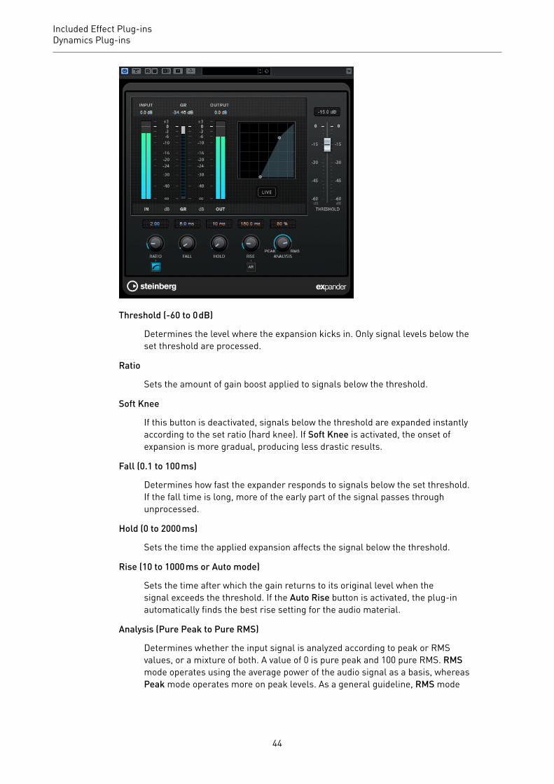
ExpanderExpander reduces the output level in relation to the input level for signals below the setthreshold. This is useful if you want to enhance the dynamic range or reduce the noise inquiet passages.
You can either use the knobs or drag the breakpoints in the graphical display to change theThreshold and the Ratio parameter values.
CubaseLE
CubaseAI
CubaseElements
CubaseArtist
CubasePro
Nuendo NEK
Included with – – – – X X –
Side-chainsupport
– – – – X X –
43
Included Effect Plug-insDynamics Plug-ins
Threshold (-60 to 0 dB)
Determines the level where the expansion kicks in. Only signal levels below theset threshold are processed.
Ratio
Sets the amount of gain boost applied to signals below the threshold.
Soft Knee
If this button is deactivated, signals below the threshold are expanded instantlyaccording to the set ratio (hard knee). If Soft Knee is activated, the onset ofexpansion is more gradual, producing less drastic results.
Fall (0.1 to 100 ms)
Determines how fast the expander responds to signals below the set threshold.If the fall time is long, more of the early part of the signal passes throughunprocessed.
Hold (0 to 2000 ms)
Sets the time the applied expansion affects the signal below the threshold.
Rise (10 to 1000 ms or Auto mode)
Sets the time after which the gain returns to its original level when thesignal exceeds the threshold. If the Auto Rise button is activated, the plug-inautomatically finds the best rise setting for the audio material.
Analysis (Pure Peak to Pure RMS)
Determines whether the input signal is analyzed according to peak or RMSvalues, or a mixture of both. A value of 0 is pure peak and 100 pure RMS. RMSmode operates using the average power of the audio signal as a basis, whereasPeak mode operates more on peak levels. As a general guideline, RMS mode
44
Included Effect Plug-insDynamics Plug-ins
works better on material with few transients such as vocals, and Peak modeworks better for percussive material with a lot of transient peaks.
Live
If this button is activated, the look-ahead feature of the effect is deactivated.Look-ahead produces more accurate processing, but adds a specific amountof latency as a trade-off. If Live mode is activated, there is no latency, which isbetter for live processing.
NOTE
If side-chaining is supported, the expansion can also be controlled from another signalsource via the side-chain input. If the side-chain signal exceeds the threshold, the expansionis triggered. For a description of how to set up side-chain routing, see the Operation Manual.
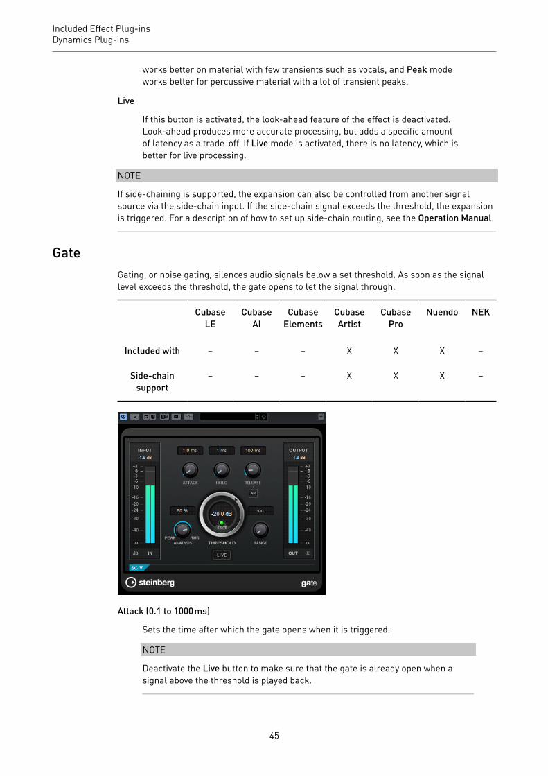
GateGating, or noise gating, silences audio signals below a set threshold. As soon as the signallevel exceeds the threshold, the gate opens to let the signal through.
CubaseLE
CubaseAI
CubaseElements
CubaseArtist
CubasePro
Nuendo NEK
Included with – – – X X X –
Side-chainsupport
– – – X X X –
Attack (0.1 to 1000 ms)
Sets the time after which the gate opens when it is triggered.
NOTE
Deactivate the Live button to make sure that the gate is already open when asignal above the threshold is played back.
45
Included Effect Plug-insDynamics Plug-ins
Hold (0 to 2000 ms)
Determines how long the gate remains open after the signal drops below thethreshold level.
Release (10 to 1000 ms or Auto mode)
Sets the time after which the gate closes (after the set Hold time). If AutoRelease is activated, Gate automatically finds the best release setting for theaudio material.
Threshold (-60 to 0 dB)
Determines the level where the gate is activated. Signal levels above the setthreshold trigger the gate to open, and signal levels below the set threshold closethe gate.
State LED
Indicates whether the gate is open (LED lights up in green), closed (LED lights upin red) or in an intermediate state (LED lights up in yellow).
Analysis (Pure Peak to Pure RMS)
Determines whether the input signal is analyzed according to peak or RMSvalues, or a mixture of both. A value of 0 is pure peak and 100 pure RMS. RMSmode operates using the average power of the audio signal as a basis, whereasPeak mode operates more on peak levels. As a general guideline, RMS modeworks better on material with few transients such as vocals, and Peak modeworks better for percussive material with a lot of transient peaks.
Range
Adjusts the attenuation of the gate when it is shut. If Range is set to minusinfinite , the gate is completely shut. The higher the value, the higher the levelof the signal that passes through the shut gate.
Live
If this button is activated, the look-ahead feature of the effect is deactivated.Look-ahead produces more accurate processing, but adds a specific amountof latency as a trade-off. If Live mode is activated, there is no latency, which isbetter for live processing.
Side-Chain SectionSide-Chain
Activates the internal side-chain filter. The input signal can then be shapedaccording to the filter parameters. Internal side-chaining is useful for tailoringhow the gate operates.
Monitor
Allows you to monitor the filtered signal.
Center (50 to 20000 Hz)
If the Side-Chain button is activated, this sets the center frequency of the filter.
46
Included Effect Plug-insDynamics Plug-ins
Q-Factor
If the Side-Chain button is activated, this sets the resonance or width of the filter.
Filter buttons (LP, BP, and HP)
If the Side-Chain button is activated, you can use these buttons to set the filtertype to low-pass, band-pass, or high-pass.
NOTE
If side-chaining is supported, the gate can also be controlled from another signal source viathe side-chain input. If the side-chain signal exceeds the threshold, the gate opens. For adescription of how to set up side-chain routing, see the Operation Manual.
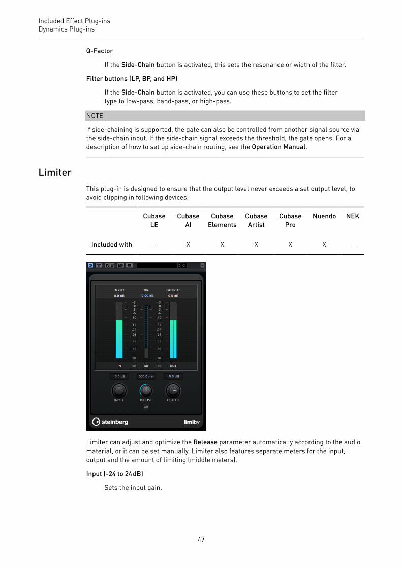
LimiterThis plug-in is designed to ensure that the output level never exceeds a set output level, toavoid clipping in following devices.
CubaseLE
CubaseAI
CubaseElements
CubaseArtist
CubasePro
Nuendo NEK
Included with – X X X X X –
Limiter can adjust and optimize the Release parameter automatically according to the audiomaterial, or it can be set manually. Limiter also features separate meters for the input,output and the amount of limiting (middle meters).
Input (-24 to 24 dB)
Sets the input gain.
47

Included Effect Plug-insDynamics Plug-ins
Release (0.1 to 1000 ms or Auto mode)
Sets the time after which the gain returns to its original level. If Auto Release isactivated, the plug-in automatically finds the best release setting for the audiomaterial.
Output
Sets the maximum output level.
MaximizerMaximizer raises the loudness of audio material without the risk of clipping. The plug-inprovides two modes, Classic and Modern, that offer different algorithms and parameters.
CubaseLE
CubaseAI
CubaseElements
CubaseArtist
CubasePro
Nuendo NEK
Included with – – X X X X –
Classic
Classic mode provides the classic algorithms from previous versions of this plug-in. This mode is suited for all styles of music.
Modern
In Modern mode, the algorithm allows for more loudness than in Classic mode.This mode is particularly suited for contemporary styles of music.
Modern mode also provides additional settings to control the release phase:
• Release sets the overall release time.
48

Included Effect Plug-insDynamics Plug-ins
• Recover allows for a faster signal recovering at the beginning of therelease phase.
Optimize
Determines the loudness of the signal.
Mix
Sets the level balance between the dry signal and the wet signal.
Output
Sets the maximum output level.
Soft Clip
If this button is activated, Maximizer starts limiting or clipping the signal softly. Atthe same time, harmonics are generated, adding a warm, tube-like characteristicto the audio material.
MIDI GateThis plug-in gates audio signals. The gate is triggered by MIDI notes.
CubaseLE
CubaseAI
CubaseElements
CubaseArtist
CubasePro
Nuendo NEK
Included with – – – X X X –
Gating, in its fundamental form, silences audio signals below a set threshold. If a signal risesabove the set level, the gate opens to let the signal through. Signals below the set level aresilenced. MIDI Gate, however, is not triggered by threshold levels, but MIDI notes. Therefore,it needs both audio and MIDI data to function.
Attack (0 to 500 ms)
Sets the time after which the gate opens when it is triggered.
Hold
Determines how long the gate remains open after a note-on or note-off message.The Hold Mode settings are taken into account.
Release (0 to 3000 ms)
Sets the time after which the gate closes after the set Hold time.
49

Included Effect Plug-insDynamics Plug-ins
Note To Attack
Determines to which extent the velocity values of the MIDI notes affect the attacktime. The higher the value, the more the attack time increases with high notevelocities. Negative values result in shorter attack times with high velocities. Ifyou do not want to use this parameter, set it to 0.
Note To Release
Determines to which extent the velocity values of the MIDI notes affect therelease time. The higher the value, the more the release time increases. If you donot want to use this parameter, set it to 0.
Velocity To VCA
Controls to which extent the velocity values of the MIDI notes determine theoutput volume. At a value of 127, the volume is controlled entirely by the velocityvalues, and at a value of 0, the velocities have no effect on the volume.
Hold Mode
Sets the Hold Mode.
• In Note-On mode, the gate only remains open for the time set with the Holdand Release parameters, regardless of the length of the MIDI note thattriggered the gate.
• In Note-Off mode, the gate remains open for as long as the MIDI noteplays. The Hold and Release parameters are applied once a note-off signalhas been received.
Setting Up MIDI GateTo use MIDI Gate for your audio, you need an audio track and a MIDI track.
PROCEDURE1. Select the audio track to which you want to apply MIDI Gate.
This can be recorded or realtime audio material from any audio track.
2. Select MIDI Gate as an insert effect for the audio track.3. Select a MIDI track to control the MIDI Gate effect.
You can either play notes on a connected MIDI keyboard or use recorded MIDI notes.
4. Open the Output Routing pop-up menu for the MIDI track and select MIDI Gate.
Applying MIDI GatePREREQUISITE
Set up the plug-in properly.
How to apply MIDI Gate depends on whether you are using realtime or recorded MIDI. Weassume for the purposes of this manual that you are using recorded audio and play the MIDIin realtime.
PROCEDURE1. If you use realtime MIDI to trigger the plug-in, make sure the MIDI track is selected.
50
Included Effect Plug-insDynamics Plug-ins
2. Start playback.3. If you use realtime MIDI, play a few notes on your keyboard.
RESULT
The MIDI notes trigger the Gate. The plug-in gates the audio signals.
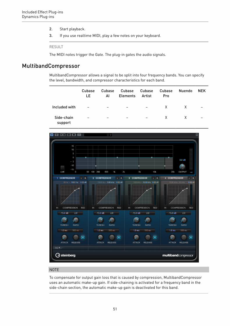
MultibandCompressorMultibandCompressor allows a signal to be split into four frequency bands. You can specifythe level, bandwidth, and compressor characteristics for each band.
CubaseLE
CubaseAI
CubaseElements
CubaseArtist
CubasePro
Nuendo NEK
Included with – – – – X X –
Side-chainsupport
– – – – X X –
NOTE
To compensate for output gain loss that is caused by compression, MultibandCompressoruses an automatic make-up gain. If side-chaining is activated for a frequency band in theside-chain section, the automatic make-up gain is deactivated for this band.
51

Included Effect Plug-insDynamics Plug-ins
Frequency Band EditorThe frequency band editor in the upper half of the panel is where you set the width of thefrequency bands as well as their level after compression. The vertical value scale to theleft shows the gain level of each frequency band. The horizontal scale shows the availablefrequency range.
• To define the frequency range of the different frequency bands, use the handles at thesides of each frequency band.
• To attenuate or boost the gain of the frequency bands by ±15 dB after compression, usethe handles at the top of each frequency band.
Live
If this button is activated, the look-ahead feature of the effect is deactivated.Look-ahead produces more accurate processing, but adds a specific amountof latency as a trade-off. If Live mode is activated, there is no latency, which isbetter for live processing.
Bypassing Frequency Bands
To bypass each frequency band, activate the Bypass Band button in eachsection.
Soloing Frequency Bands
To solo a frequency band, activate the S button in each section. Only one band canbe soloed at a time.
Output (-24 to 24 dB)
Sets the output level.
Compressor SectionYou can specify the Threshold and Ratio by moving breakpoints or using the correspondingknobs. The threshold is marked by the first breakpoint where the line deviates from thestraight diagonal.
Threshold (-60 to 0 dB)
Determines the level where the compressor kicks in. Only signal levels above theset threshold are processed.
Ratio
Sets the amount of gain reduction applied to signals above the set threshold. Aratio of 3:1 means that for every 3 dB the input level increases, the output levelincreases by 1 dB.
Attack (0.1 to 100 ms)
Determines how fast the compressor responds to signals above the setthreshold. If the attack time is long, more of the early part of the signal passesthrough unprocessed.
52
Included Effect Plug-insDynamics Plug-ins
Release (10 to 1000 ms or Auto mode)
Sets the time after which the gain returns to its original level when thesignal drops below the threshold. If the Auto button is activated, the plug-inautomatically finds the best release setting for the audio material.
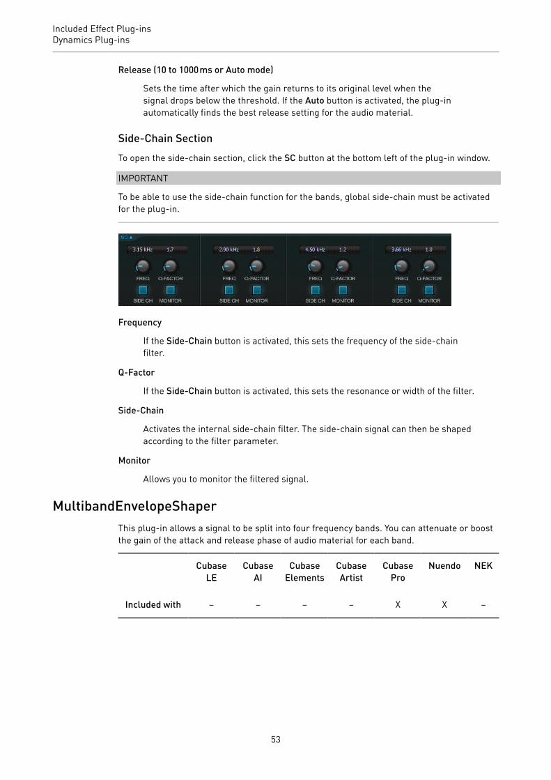
Side-Chain SectionTo open the side-chain section, click the SC button at the bottom left of the plug-in window.
IMPORTANT
To be able to use the side-chain function for the bands, global side-chain must be activatedfor the plug-in.
Frequency
If the Side-Chain button is activated, this sets the frequency of the side-chainfilter.
Q-Factor
If the Side-Chain button is activated, this sets the resonance or width of the filter.
Side-Chain
Activates the internal side-chain filter. The side-chain signal can then be shapedaccording to the filter parameter.
Monitor
Allows you to monitor the filtered signal.
MultibandEnvelopeShaperThis plug-in allows a signal to be split into four frequency bands. You can attenuate or boostthe gain of the attack and release phase of audio material for each band.
CubaseLE
CubaseAI
CubaseElements
CubaseArtist
CubasePro
Nuendo NEK
Included with – – – – X X –
53
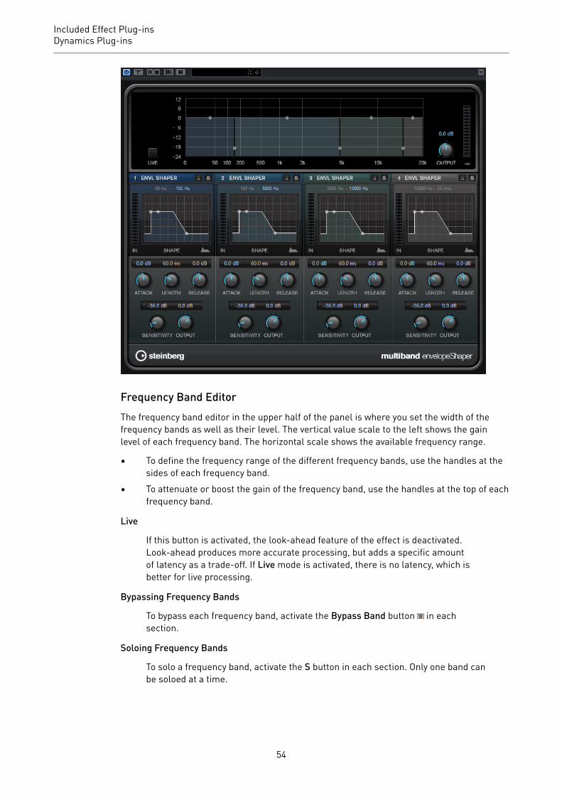
Included Effect Plug-insDynamics Plug-ins
Frequency Band EditorThe frequency band editor in the upper half of the panel is where you set the width of thefrequency bands as well as their level. The vertical value scale to the left shows the gainlevel of each frequency band. The horizontal scale shows the available frequency range.
• To define the frequency range of the different frequency bands, use the handles at thesides of each frequency band.
• To attenuate or boost the gain of the frequency band, use the handles at the top of eachfrequency band.
Live
If this button is activated, the look-ahead feature of the effect is deactivated.Look-ahead produces more accurate processing, but adds a specific amountof latency as a trade-off. If Live mode is activated, there is no latency, which isbetter for live processing.
Bypassing Frequency Bands
To bypass each frequency band, activate the Bypass Band button in eachsection.
Soloing Frequency Bands
To solo a frequency band, activate the S button in each section. Only one band canbe soloed at a time.
54

Included Effect Plug-insDynamics Plug-ins
Output (-24 to 24 dB)
Sets the output level.
Shaper SectionYou can specify the Attack, Length, and Release by moving breakpoints or using thecorresponding knobs. Be careful with levels when boosting the gain. You can reduce theoutput level to avoid clipping.
Attack (-20 to 20 dB)
Sets the gain of the attack phase of the signal.
Length (5 to 200 ms)
Sets the length of the attack phase.
Release (-20 to 20 dB)
Sets the gain of the release phase of the signal.
Sensitivity (-40 to -10 dB)
Sets the sensitivity of the detection.
Output
Sets the output level.
MultibandExpanderThis plug-in allows a signal to be split into four frequency bands. You can reduce the outputlevel in relation to the input level for signals below the set threshold for each band. This isuseful if you want to enhance the dynamic range or reduce the noise in quiet passages.
CubaseLE
CubaseAI
CubaseElements
CubaseArtist
CubasePro
Nuendo NEK
Included with – – – – X X –
Side-chainsupport
– – – – X X –
55

Included Effect Plug-insDynamics Plug-ins
Frequency Band EditorThe frequency band editor in the upper half of the panel is where you set the width of thefrequency bands as well as their level after expansion. The vertical value scale to the leftshows the gain level of each frequency band. The horizontal scale shows the availablefrequency range.
• To define the frequency range of the different frequency bands, use the handles at thesides.
• To attenuate or boost the gain of the frequency band after expansion, use the handleson top of each frequency band.
Live
If this button is activated, the look-ahead feature of the effect is deactivated.Look-ahead produces more accurate processing, but adds a specific amountof latency as a trade-off. If Live mode is activated, there is no latency, which isbetter for live processing.
Bypassing Frequency Bands
To bypass each frequency band, activate the Bypass Band button in eachsection.
Soloing Frequency Bands
To solo a frequency band, activate the S button in each section. Only one band canbe soloed at a time.
56

Included Effect Plug-insDynamics Plug-ins
Output (-24 to 24 dB)
Sets the output level.
Expander SectionYou can specify the Threshold and Ratio by moving breakpoints or using the correspondingknobs. The first breakpoint from which the line deviates from the straight diagonal is thethreshold point.
Threshold (-60 to 0 dB)
Determines the level where the expansion kicks in. Only signal levels below theset threshold are processed.
Ratio
Sets the amount of gain boost applied to signals below the threshold.
Maximum Reduction
Sets the maximum amount by which the level is reduced when the signal fallsbelow the set threshold.
Fall (0.1 to 100 ms)
Determines how fast the expander responds to signals below the set threshold.If the fall time is long, more of the early part of the signal passes throughunprocessed.
Hold (0 to 2000 ms)
Sets the time the applied expansion affects the signal below the threshold.
Rise (10 to 1000 ms or Auto mode)
Sets the time after which the gain returns to its original level when thesignal exceeds the threshold. If the Auto Rise button is activated, the plug-inautomatically finds the best rise setting for the audio material.
Output
Sets the output level.
Side-Chain Section
Frequency
If the Side-Chain button is activated, this sets the frequency of the side-chainfilter.
Q-Factor
If the Side-Chain button is activated, this sets the resonance or width of the filter.
57
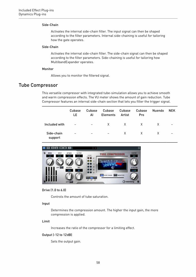
Included Effect Plug-insDynamics Plug-ins
Side-Chain
Activates the internal side-chain filter. The input signal can then be shapedaccording to the filter parameters. Internal side-chaining is useful for tailoringhow the gate operates.
Side-Chain
Activates the internal side-chain filter. The side-chain signal can then be shapedaccording to the filter parameters. Side-chaining is useful for tailoring howMultibandExpander operates.
Monitor
Allows you to monitor the filtered signal.
Tube CompressorThis versatile compressor with integrated tube-simulation allows you to achieve smoothand warm compression effects. The VU meter shows the amount of gain reduction. TubeCompressor features an internal side-chain section that lets you filter the trigger signal.
CubaseLE
CubaseAI
CubaseElements
CubaseArtist
CubasePro
Nuendo NEK
Included with – – X X X X –
Side-chainsupport
– – – X X X –
Drive (1.0 to 6.0)
Controls the amount of tube saturation.
Input
Determines the compression amount. The higher the input gain, the morecompression is applied.
Limit
Increases the ratio of the compressor for a limiting effect.
Output (-12 to 12 dB)
Sets the output gain.
58

Included Effect Plug-insDynamics Plug-ins
Attack (0.1 to 100 ms)
Determines how fast the compressor responds. If the attack time is long, more ofthe initial part of the signal passes through unprocessed.
Release (10 to 1000 ms or Auto mode)
Sets the time after which the gain returns to its original level. If the Auto buttonis activated, the plug-in automatically finds the best release setting for the audiomaterial.
Mix
Adjusts the mix between dry signal and wet signal preserving the transients ofthe input signal.
In/Out Meters
Show the highest peaks of all available input and output channels.
VU Meter
Shows the amount of gain reduction.
Side-Chain
Activates the internal side-chain filter. The input signal can then be shapedaccording to the filter parameters. Internal side-chaining is useful for tailoringhow the gate operates.
Filter buttons (LP, BP, and HP)
If the Side-Chain button is activated, you can use these buttons to set the filtertype to low-pass, band-pass, or high-pass.
Side-chain sectionCenter (50 to 20000 Hz)
If the Side-Chain button is activated, this sets the center frequency of the filter.
Q-Factor
If the Side-Chain button is activated, this sets the resonance or width of the filter.
Monitor
Allows you to monitor the filtered signal.
VintageCompressorVintageCompressor is modeled after vintage type compressors.
CubaseLE
CubaseAI
CubaseElements
CubaseArtist
CubasePro
Nuendo NEK
Included with – – X X X X –
59
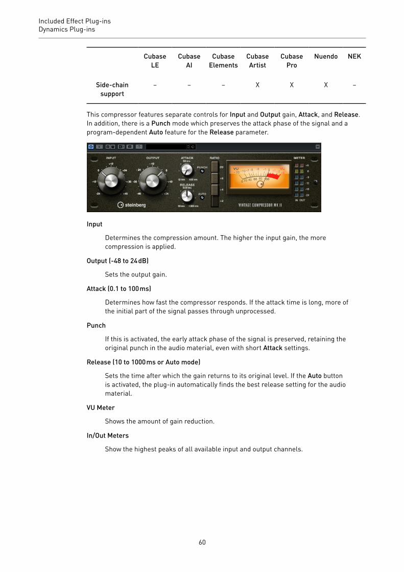
Included Effect Plug-insDynamics Plug-ins
CubaseLE
CubaseAI
CubaseElements
CubaseArtist
CubasePro
Nuendo NEK
Side-chainsupport
– – – X X X –
This compressor features separate controls for Input and Output gain, Attack, and Release.In addition, there is a Punch mode which preserves the attack phase of the signal and aprogram-dependent Auto feature for the Release parameter.
Input
Determines the compression amount. The higher the input gain, the morecompression is applied.
Output (-48 to 24 dB)
Sets the output gain.
Attack (0.1 to 100 ms)
Determines how fast the compressor responds. If the attack time is long, more ofthe initial part of the signal passes through unprocessed.
Punch
If this is activated, the early attack phase of the signal is preserved, retaining theoriginal punch in the audio material, even with short Attack settings.
Release (10 to 1000 ms or Auto mode)
Sets the time after which the gain returns to its original level. If the Auto buttonis activated, the plug-in automatically finds the best release setting for the audiomaterial.
VU Meter
Shows the amount of gain reduction.
In/Out Meters
Show the highest peaks of all available input and output channels.
60
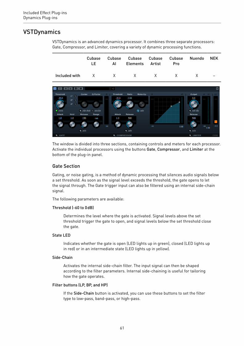
Included Effect Plug-insDynamics Plug-ins
VSTDynamicsVSTDynamics is an advanced dynamics processor. It combines three separate processors:Gate, Compressor, and Limiter, covering a variety of dynamic processing functions.
CubaseLE
CubaseAI
CubaseElements
CubaseArtist
CubasePro
Nuendo NEK
Included with X X X X X X –
The window is divided into three sections, containing controls and meters for each processor.Activate the individual processors using the buttons Gate, Compressor, and Limiter at thebottom of the plug-in panel.
Gate SectionGating, or noise gating, is a method of dynamic processing that silences audio signals belowa set threshold. As soon as the signal level exceeds the threshold, the gate opens to letthe signal through. The Gate trigger input can also be filtered using an internal side-chainsignal.
The following parameters are available:
Threshold (-60 to 0 dB)
Determines the level where the gate is activated. Signal levels above the setthreshold trigger the gate to open, and signal levels below the set threshold closethe gate.
State LED
Indicates whether the gate is open (LED lights up in green), closed (LED lights upin red) or in an intermediate state (LED lights up in yellow).
Side-Chain
Activates the internal side-chain filter. The input signal can then be shapedaccording to the filter parameters. Internal side-chaining is useful for tailoringhow the gate operates.
Filter buttons (LP, BP, and HP)
If the Side-Chain button is activated, you can use these buttons to set the filtertype to low-pass, band-pass, or high-pass.
61

Included Effect Plug-insDynamics Plug-ins
Center (50 to 20000 Hz)
If the Side-Chain button is activated, this sets the center frequency of the filter.
Q-Factor
If the Side-Chain button is activated, this sets the resonance or width of the filter.
Monitor
Allows you to monitor the filtered signal.
Attack (0.1 to 100 ms)
Determines how fast the compressor responds to signals above the setthreshold. If the attack time is long, more of the early part of the signal passesthrough unprocessed.
Hold (0 to 2000 ms)
Determines how long the gate remains open after the signal drops below thethreshold level.
Release (10 to 1000 ms or Auto mode)
Sets the time after which the gate closes after the set Hold time. If the Autobutton is activated, the plug-in automatically finds the best release setting for theaudio material.
Range
Adjusts the attenuation of the gate when it is shut. If Range is set to minusinfinite , the gate is completely shut. The higher the value, the higher the levelof the signal that passes through the shut gate.
Input Gain Meter
Shows the input gain.
Compressor SectionThe compressor reduces the dynamic range of the audio, making softer sounds louder orlouder sounds softer, or both. The compressor features a separate display that graphicallyillustrates the compressor curve shaped according to your settings.
Threshold (-60 to 0 dB)
Determines the level where the compressor kicks in. Only signal levels above theset threshold are processed.
Ratio
Sets the amount of gain reduction applied to signals above the set threshold. Aratio of 3:1 means that for every 3 dB the input level increases, the output levelincreases by 1 dB.
Make-Up (0 to 24 dB or Auto mode)
Compensates for output gain loss, caused by compression. If the Auto button isactivated, the knob becomes dark and the output is automatically adjusted forgain loss.
62
Included Effect Plug-insDynamics Plug-ins
Attack (0.1 to 100 ms)
Determines how fast the compressor responds to signals above the setthreshold. If the attack time is long, more of the early part of the signal (attack)passes through unprocessed.
Release (10 to 1000 ms or Auto mode)
Sets the time after which the gain returns to its original level when thesignal drops below the threshold. If the Auto button is activated, the plug-inautomatically finds the best release setting for the audio material.
Graphical display
Use the graphical display to graphically set the threshold and ratio values. To theleft and right of the graphical display, you find two meters that show the amountof gain reduction in dB.
Limiter SectionThe limiter ensures that the output level never exceeds a set threshold, to avoid clipping infollowing devices. Conventional limiters usually require very accurate setting up of the attackand release parameters to prevent the output level from going beyond the set thresholdlevel. The limiter adjusts and optimizes these parameters automatically according to theaudio material.
Output
Sets the maximum output level.
Soft Clip
If this button is activated, the signal is limited when the signal level exceeds-6 dB. At the same time, harmonics are generated, adding a warm, tube-likecharacteristic to the audio material.
Release (10 to 1000 ms or Auto mode)
Sets the time after which the gain returns to its original level. If the Auto buttonis activated, the plug-in automatically finds the best release setting for the audiomaterial.
Meters
The three meters show the input gain (IN), the gain reduction (GR) and the outputgain (OUT).
Module Configuration ButtonUsing the Module Configuration button in the bottom right corner of the plug-in panel, youcan set the signal flow order for the three processors. Changing the order of the processorscan produce different results, and the available options allow you to quickly compare whatworks best for a given situation. Simply click the Module Configuration button to change to adifferent configuration. There are three routing options:
• C-G-L (Compressor-Gate-Limit)• G-C-L (Gate-Compressor-Limit)• C-L-G (Compressor-Limit-Gate)
63

Included Effect Plug-insEQ Plug-ins
EQ Plug-ins
CurveEQVoxengo CurveEQ is a spline equalizer for professional music and audio productionapplications. CurveEQ shows the filter response you are designing by means of a spline, thatis, a smooth curvy line. This way you can see how the EQ alters the sound.
CubaseLE
CubaseAI
CubaseElements
CubaseArtist
CubasePro
Nuendo NEK
Included with – – – – X X –
CurveEQ implements spectrum matching technology that allows you to transfer the spectralshape of one recording to another. In other words, you can copy the frequency balance ofexisting time-proven mixes so that other mixes can be improved. CurveEQ’s filters canbe switched between linear-phase and minimum-phase modes. CurveEQ also featuresa customizable spectrum analyzer. Furthermore, you can display, save, and load staticspectrum plots for comparison and matching purposes.
For detailed information about CurveEQ and its parameters, refer to the documentationprovided by Voxengo at http://www.voxengo.com.
DJ-EQThis plug-in is an easy-to-use 3-band parametric equalizer that resembles the EQs found ontypical DJ mixers. This plug-in is designed for quick sound fixes.
CubaseLE
CubaseAI
CubaseElements
CubaseArtist
CubasePro
Nuendo NEK
Included with X X X X X X –
• To set the Low, Mid, and Hi frequency bands, click and drag the EQ points.
64

Included Effect Plug-insEQ Plug-ins
• To fine-adjust the Low, Mid, and Hi frequency bands, press Shift and drag the EQpoints.
• To set a parameter to zero, press Ctrl/Cmd and click it.• To change the Gain values, click them and move the mouse up or down.
Low Gain
Sets the amount of boost or attenuation for the low band.
Low Kill (Activates Low Cut)
Cuts the low band.
Mid Gain
Sets the amount of attenuation/boost for the mid band.
Mid Kill (Activates Mid Cut)
Cuts the mid band.
Hi Gain
Sets the amount of boost or attenuation for the high band.
Hi Kill (Activates High Cut)
Cuts the high band.
Output meter
Indicates the level of the output signal.
GEQ-10/GEQ-30These graphic equalizers are identical, except for the number of available frequency bands(10 and 30).
CubaseLE
CubaseAI
CubaseElements
CubaseArtist
CubasePro
Nuendo NEK
Included with –/– –/– –/– X/– X/X X/X –/–
65

Included Effect Plug-insEQ Plug-ins
Each band can be attenuated or boosted by up to 12 dB, allowing for fine control of thefrequency response. In addition, there are several preset modes available that can add colorto the sound of GEQ-10/GEQ-30.
You can draw response curves in the main display by clicking and dragging with the mouse.You have to click one of the sliders before you drag across the display.
At the bottom of the window, the individual frequency bands are shown in Hz. At the top of thedisplay, the amount of attenuation/boost is shown in dB.
Output
Sets the overall gain of the equalizer.
Flatten
Resets all the frequency bands to 0 dB.
Range
Allows you to adjust how much a set curve cuts or boosts the signal.
Invert
Inverts the current response curve.
Mode pop-up menu
This pop-up menu allows you to set the filter mode that determines how thevarious frequency band controls interact to create the response curve.
EQ ModesThe Mode pop-up menu in the lower right corner allows you to select an EQ mode, which addcolor or character to the equalized output in various ways.
True Response
Applies serial filters with an accurate frequency response.
Digi Standard
In this mode, the resonance of the last band depends on the sample rate.
Classic
Applies a classic parallel filter structure where the response does not follow theset gain values accurately.
VariableQ
Applies parallel filters where the resonance depends on the amount of gain.
ConstQ u
Applies parallel filters where the resonance of the first and last bands dependson the sample rate.
ConstQ s
Applies parallel filters where the resonance is raised when boosting the gain andvice versa.
66

Included Effect Plug-insEQ Plug-ins
Resonant
Applies serial filters where a gain increase of one band lowers the gain inadjacent bands.
StudioEQStudio EQ is a high-quality 4-band parametric stereo equalizer with two fully parametricmid-range bands. The low and high bands can act as either shelving filters (three types), oras peak filter (band-pass), or as cut filter (low-pass/high-pass).
CubaseLE
CubaseAI
CubaseElements
CubaseArtist
CubasePro
Nuendo NEK
Included with – – X X X X –
Gain (-20 to +24 dB)
Sets the amount of attenuation/boost for the corresponding band.
Inv
Inverts the gain value of the filter. Use this button to filter out unwanted noise.When looking for the frequency to omit, it sometimes helps to boost it in the firstplace (set the filter to positive gain). After you have found the frequency of thenoise, you can use the Inv button to cancel it out.
Freq (20 to 20000 Hz)
Sets the frequency of the corresponding band. You can set the frequency eitherin Hz or as a note value. If you enter a note value, the frequency is automaticallychanged to Hz. For example, a note value of A3 sets the frequency to 440 Hz.When you enter a note value, you can also enter a cent offset. For example, enterA5 -23 or C4 +49.
NOTE
Ensure that you enter a space between the note and the cent offset. Only in thiscase, the cent offsets are taken into account.
67

Included Effect Plug-insEQ Plug-ins
Q-Factor
Controls the width, or resonance, of the corresponding band.
Filter mode
For the low and high band, you can choose between three types of shelvingfilters, a peak filter (band-pass), and a cut filter (lowpass/high-pass). If Cut modeis selected, the Gain parameter is fixed.
• Shelf I adds resonance in the opposite gain direction slightly above the setfrequency.
• Shelf II adds resonance in the gain direction at the set frequency.• Shelf III is a combination of Shelf I and II.
Output (-24 to +24 dB)
This knob on the top right of the plug-in panel allows you to adjust the overalloutput level.
Auto Gain
If this button is activated, the gain is automatically adjusted, keeping the outputlevel constant regardless of the EQ settings.
Spectrum
Shows the spectrum before and after filtering.
Reset
Resets the EQ settings.
Making Settings
PROCEDURE1. Click the corresponding On/Off button on the left of the plug-in panel to activate any or
all of the 4 equalizer bands (Low, Mid 1, Mid 2, and High).If a band is activated, the corresponding EQ point appears in the EQ curve display.
2. Set the parameters for an activated EQ band.This can be done in several ways:
• By using the knobs.• By clicking on the numeric values and entering new values.• By dragging points in the EQ curve display.
Using Modifier KeysWhen using the mouse to change the parameter settings, modifier keys can be used. Whenno modifier key is pressed and you drag an EQ point in the display, the Gain and Frequencyparameters are adjusted simultaneously.
Shift
If you keep Shift pressed and drag the mouse, the Q-factor of the correspondingEQ band is modified.
68

Included Effect Plug-insEQ Plug-ins
Alt
If you keep Alt pressed and drag the mouse, the frequency of the correspondingEQ band is modified.
Ctrl/Cmd
If you keep Ctrl/Cmd pressed and drag the mouse, the gain value of thecorresponding EQ band is modified.
FrequencyFrequency is a high-quality equalizer with 8 fully parametric bands. The bands can act aseither shelving filter, as peak or notch filter (band-pass), or as cut filter (low-pass/high-pass).
CubaseLE
CubaseAI
CubaseElements
CubaseArtist
CubasePro
Nuendo NEK
Included with – – – – X X –
Main LayoutReset
Resets all parameter values.
69

Included Effect Plug-insEQ Plug-ins
Auto Listen for Filters
If this option is activated and you edit a parameter of a band, the correspondingfrequency range is isolated. This helps you to focus on a particular frequencyrange and allows you to locate unwanted frequencies in your audio.
Global Settings
Opens the settings dialog for the spectrum display.
Show/Hide Keyboard
Shows/Hides the keyboard below the graphical editor.
On the keyboard, color indicators reflect the center frequencies of all activeequalizer bands. You can adjust the frequency of a band by dragging its colorindicator. If you drag the color indicator of a band to a key, the band is set to itsexact frequency.
Output
Adjusts the overall output level.
Band Settings
On/Off
Activates/Deactivates the corresponding band.
Processing Switches
Allow you to switch between left/right, stereo, and mid/side processing. In Left/Right or Mid/Side processing mode, you can make different settings for the twochannels.
NOTE
This setting is only available for stereo tracks.
Linear Phase
Activates/Deactivates linear phase mode for the corresponding band.
Linear phase mode avoids unwanted frequency dependent phase shifts of theaudio signal that might occur with standard minimum phase equalizing.
NOTE
• Linear phase mode leads to an increase in latency.• In rare cases, for example, when using low cut filtering with a high slope
for bass signals, also an unwanted pre-ringing effect may be audible.
70

Included Effect Plug-insEQ Plug-ins
Equalizer Section
Type
You can choose between the EQ types Low Shelf, Peak, High Shelf, and Notch.For band 1 and 8, you can also select the types Cut 6, Cut 12, Cut 24, Cut 48, andCut 96.
• Low Shelf boosts or attenuates frequencies below the cutoff frequency bythe specified amount.
• Peak boosts or attenuates frequencies at the set frequency value with abell shaped filter.
• High Shelf boosts or attenuates frequencies above the cutoff frequency bythe specified amount.
• Notch boosts or attenuates frequencies at the set frequency value with avery narrow filter.
• Cut attenuates frequencies below (band 1) or above (band 8) the setfrequency. You can choose between different slopes: 6 dB, 12 dB, 24 dB, 48 dB, or 96 dB per octave.
FREQ
Sets the center frequency of the corresponding band.
If the band is active, the frequency value is reflected as a highlighted key on thekeyboard below the graphical editor.
Q
For Peak and Notch filters, this parameter controls the width of the band. ForLow Shelf and High Shelf filters, it adds a drop or a boost, depending on the gainsetting of the band. For Cut filters, it adds a resonance.
NOTE
This parameter is not available for Cut 6 filters.
Gain
Sets the amount of attenuation/boost for the corresponding band.
71

Included Effect Plug-insEQ Plug-ins
Invert Gain
Inverts the value of the gain parameter. Positive gain values become negative andvice versa.
Global Settings
• To open the Global Settings, click Global Settings above the spectrum display.
Spectrum DisplayShow Spectrum
Activates/Deactivates the spectrum display.
Peak Hold
Holds the peak values of the spectrum display for a short time.
Smooth
Determines the reaction time of the spectrum display. Lower values result infaster reaction times.
Bar Graph
If this option is activated, the frequency spectrum is analyzed into 60 separatebands that are displayed as vertical bars.
Two Channels
If this option is activated, the spectrum of the left and right channels aredisplayed separately.
Slope
Tilts the spectrum display around the 1 kHz pivot.
EQ CurveShow Curve
Shows/Hides the EQ curve in the spectrum display.
Filled
If this option is activated, the EQ curve is filled. Amount allows you to specify thedegree of coverage between 10 and 80 %.
72

Included Effect Plug-insFilter Plug-ins
Filter Plug-ins
DualFilterThis plug-in filters out specific frequencies while allowing others to pass through.
CubaseLE
CubaseAI
CubaseElements
CubaseArtist
CubasePro
Nuendo NEK
Included with X X X X X X –
Position
Sets the filter cutoff frequency. If you set this to a negative value, DualFilter actsas a low-pass filter. Positive values cause DualFilter to act as a high-pass filter.
Resonance
Sets the sound characteristic of the filter. With higher values, a ringing sound isheard.
MorphFilterThis plug-in lets you mix low-pass, high-pass, band-pass, and band-reduction filter effects,allowing for creative morphings between two filters.
CubaseLE
CubaseAI
CubaseElements
CubaseArtist
CubasePro
Nuendo NEK
Included with – – X X X X –
73

Included Effect Plug-insFilter Plug-ins
1. High Pass (6, 12, 18, 24 dB per decade)Eliminates low-frequency signal components. Several filter slopes are available.
2. Band Rejection (12, 24 dB/per decade)Lets all frequencies pass, except those in the stop band. Several filter slopes areavailable.
3. Resonance FactorChanges the resonance value of the filters.
4. x/y controlAdjusts the Morph Factor and the Frequency parameters simultaneously.
5. Morph FactorLets you mix the output between the two selected filters.
6. Level meterShows the output level, giving you an indication of how the filtering affects the overalllevel of the edited event.
7. FrequencyAdjusts the cutoff frequency of the filters.
8. Band Pass (12, 24 dB per decade)Allows signals falling within a certain frequency range to pass through. Several filterslopes are available.
9. Low Pass (6, 12, 18, 24 dB per decade)Eliminates high-frequency signal components. Several filter slopes are available.
74

Included Effect Plug-insFilter Plug-ins
PostFilterThis effect allows quick and easy filtering of unwanted frequencies, creating room for theimportant sounds in your mix.
CubaseLE
CubaseAI
CubaseElements
CubaseArtist
CubasePro
Nuendo NEK
Included with – – – – – X –
The PostFilter plug-in combines a low-cut filter, a notch filter, and a high-cut filter. Youcan make settings by dragging the curve points in the graphical display, or by adjusting thecontrols below the display section.
Level meter
Shows the output level, giving you an indication of how the filtering affects theoverall level of the edited audio.
Low Cut Freq (20 Hz to 1 kHz, or Off)
Allows you to eliminate low-frequency noise. The filter is inactive if the curvepoint is located all the way to the left. You can set the frequency either in Hz or asa note value. If you enter a note value, the frequency is automatically changed toHz. For example, a note value of A3 sets the frequency to 440 Hz. When you entera note value, you can also enter a cent offset. For example, enter A5 -23 or C4+49.
NOTE
Ensure that you enter a space between the note and the cent offset. Only in thiscase, the cent offsets are taken into account.
Low Cut Slope
Allows you to choose a slope value for the low-cut filter.
75

Included Effect Plug-insFilter Plug-ins
Low Cut Preview
Use this button between the Low Cut Freq button and the graphical display toswitch the filter to a complementary high-cut filter. This deactivates any otherfilters, allowing you to listen only to the frequencies that you want to filter out.
Notch Freq
Sets the frequency of the notch filter. You can set the frequency either in Hz or asa note value. If you enter a note value, the frequency is automatically changed toHz. For example, a note value of A3 sets the frequency to 440 Hz. When you entera note value, you can also enter a cent offset. For example, enter A5 -23 or C4+49.
NOTE
Ensure that you enter a space between the note and the cent offset. Only in thiscase, the cent offsets are taken into account.
Notch Gain
Adjusts the gain of the selected frequency. Use positive values to identify thefrequencies that you want to filter out.
Notch Gain Invert
This button inverts the gain value of the notch filter. Use this button to filter outunwanted noise. When looking for the frequency to omit, it sometimes helps toboost it first (set the notch filter to positive gain). After you have found frequencyof the noise, you can use the Invert button to cancel it out.
Notch Q-Factor
Sets the width of the notch filter.
Notch Preview
Use the Preview button between the notch filter buttons and the graphicaldisplay to create a band-pass filter with the peak filter's frequency and Q. Thisdeactivates any other filters, allowing you to listen only to the frequencies youwant to filter out.
Notches buttons (1, 2, 4, 8)
These buttons add additional notch filters to filter out harmonics.
High Cut Freq (3 Hz to 20 kHz, or Off)
This high-cut filter allows you to remove high-frequency noise. The filter isinactive if the curve point is located all the way to the right. You can set thefrequency either in Hz or as a note value. If you enter a note value, the frequencyis automatically changed to Hz. For example, a note value of A3 sets thefrequency to 440 Hz. When you enter a note value, you can also enter a centoffset. For example, enter A5 -23 or C4 +49.
NOTE
Ensure that you enter a space between the note and the cent offset. Only in thiscase, the cent offsets are taken into account.
76

Included Effect Plug-insFilter Plug-ins
High Cut Slope
Allows you to choose a slope value for the high-cut filter.
High Cut Preview
This button between the High Cut Freq button and the graphical display allowsyou to switch the filter to a complementary low-cut filter. This deactivates anyother filters, allowing you to listen only to the frequencies you want to filter out.
StepFilterThis plug-in is a pattern-controlled multimode filter that can create rhythmic, pulsating filtereffects.
CubaseLE
CubaseAI
CubaseElements
CubaseArtist
CubasePro
Nuendo NEK
Included with – – X X X X –
General OperationStepFilter can produce two simultaneous 16-step patterns for the filter cutoff and resonanceparameters, synchronized to the sequencer tempo.
The horizontal axis shows the pattern steps 1 to 16 from left to right, and the vertical axisdetermines the (relative) filter cutoff frequency and resonance settings. The higher up onthe vertical axis a step value is entered, the higher the relative filter cutoff frequency or filterresonance setting.
By starting playback and editing the patterns for the cutoff and resonance parameters, youcan hear how your filter patterns affect the sound source connected to StepFilter.
Setting Step Values• To enter a step, click in the pattern grid windows.• Individual step entries can be dragged up or down the vertical axis, or directly set by
clicking in an empty grid box. By click-dragging left or right, consecutive step entriesare set at the pointer position.
• Change the value for a step by dragging it up or down.• Draw in a curve by clicking and dragging in the display.
77

Included Effect Plug-insFilter Plug-ins
Selecting New Patterns• Patterns are saved with the project, and up to 8 different cutoff and resonance patterns
can be saved internally. Both the cutoff and resonance settings are saved together inthe 8 pattern slots.
• Use the Pattern Select knob below the Resonance grid to select a new pattern. Newpatterns are all set to the same step value by default.
StepFilter ParametersBase Cutoff
Sets the base filter cutoff frequency. Values set in the Cutoff grid are relative tothe Base Cutoff value.
Base Resonance
Sets the base filter resonance. Values set in the Resonance grid are relative tothe Base Resonance value.
NOTE
Very high Base Resonance settings can produce loud ringing effects at certainfrequencies.
Glide
Applies glide between the pattern steps, causing values to change moresmoothly.
Filter mode
Use this slider to select a filter mode: low-pass, band-pass, or high-pass (fromleft to right).
Sync
If the Sync button to the right of the Sync pop-up menu is activated (yellow), thepattern playback is synchronized to the project tempo.
Use the pop-up menu to set the pattern beat resolution, that is, the note valuesthe pattern plays in relation to the tempo (1/1 to 1/32, straight, triplet, or dotted).
Output
Sets the output level.
Mix
Sets the level balance between the dry signal and the wet signal.
Creating Variations for StepFilter PatternsYou can copy a pattern of the StepFilter to another pattern slot. This is useful for creatingvariations on a pattern of this plug-in.
PROCEDURE1. Select the pattern that you want to copy.2. Click the Copy button.
78
Included Effect Plug-insFilter Plug-ins
3. Select another pattern slot.4. Click the Paste button.
RESULT
The pattern is copied to the new slot, and can now be edited to create variations.
ToneBoosterToneBooster is a filter that allows you to raise the gain in a selected frequency range. Itis particularly useful if it is inserted before AmpSimulator in the plug-in chain, greatlyenhancing the tonal varieties available.
CubaseLE
CubaseAI
CubaseElements
CubaseArtist
CubasePro
Nuendo NEK
Included with – X X X X X –
Tone
Sets the center filter frequency.
Gain
Adjusts the gain of the selected frequency range by up to 24 dB.
Width
Sets the resonance of the filter.
Mode selector
Sets the basic operational mode of the filter: Peak or Band Mode.
RELATED LINKSAmpSimulator on page 10
WahWahThis plug-in is a variable slope band-pass filter that can be auto-controlled by a side-chainsignal (if supported) or via MIDI modeling the well-known analog pedal effect.
CubaseLE
CubaseAI
CubaseElements
CubaseArtist
CubasePro
Nuendo NEK
Included with – X X X X X –
79
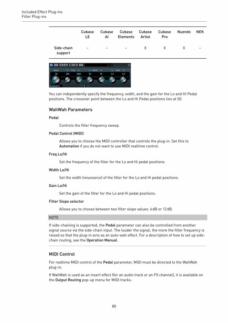
Included Effect Plug-insFilter Plug-ins
CubaseLE
CubaseAI
CubaseElements
CubaseArtist
CubasePro
Nuendo NEK
Side-chainsupport
– – – X X X –
You can independently specify the frequency, width, and the gain for the Lo and Hi Pedalpositions. The crossover point between the Lo and Hi Pedal positions lies at 50.
WahWah ParametersPedal
Controls the filter frequency sweep.
Pedal Control (MIDI)
Allows you to choose the MIDI controller that controls the plug-in. Set this toAutomation if you do not want to use MIDI realtime control.
Freq Lo/Hi
Set the frequency of the filter for the Lo and Hi pedal positions.
Width Lo/Hi
Set the width (resonance) of the filter for the Lo and Hi pedal positions.
Gain Lo/Hi
Set the gain of the filter for the Lo and Hi pedal positions.
Filter Slope selector
Allows you to choose between two filter slope values: 6 dB or 12 dB.
NOTE
If side-chaining is supported, the Pedal parameter can also be controlled from anothersignal source via the side-chain input. The louder the signal, the more the filter frequency israised so that the plug-in acts as an auto-wah effect. For a description of how to set up side-chain routing, see the Operation Manual.
MIDI ControlFor realtime MIDI control of the Pedal parameter, MIDI must be directed to the WahWahplug-in.
If WahWah is used as an insert effect (for an audio track or an FX channel), it is available onthe Output Routing pop-up menu for MIDI tracks.
80

Included Effect Plug-insMastering Plug-ins
If WahWah is selected on the Output Routing menu, MIDI data is directed to the plug-in fromthe selected track.
Mastering Plug-ins
UV22HRThis is an advanced version of Apogee's renowned UV22 dithering algorithm, capable ofdithering to 8, 16, 20, or 24 bits.
CubaseLE
CubaseAI
CubaseElements
CubaseArtist
CubasePro
Nuendo NEK
Included with – – X X X X –
8, 16, 20, 24 bit
These buttons allow you to select the intended bit resolution for the final audio.As when using the internal dithering, it is important to set this to the correctresolution.
Hi
Applies a normal dither gain.
Lo
Applies a lower level of dither noise.
Auto black
If this option is activated, the dither noise is gated during silent passages.
IMPORTANT
Dithering should always be applied post-fader on an output bus.
81

Included Effect Plug-insModulation Plug-ins
Modulation Plug-ins
AutoPanThis auto-pan effect provides several parameters to modulate the left/right stereo position.You can use presets or create individual curves for the modulation waveform. The plug-inalso allows for chopping effects by linking the modulation of left and right channel.
CubaseLE
CubaseAI
CubaseElements
CubaseArtist
CubasePro
Nuendo NEK
Included with X X X X X X –
Side-chainsupport
– – – X X X –
NOTE
The panning effect of this plug-in works only on stereo tracks.
Waveform display
Shows the shape of the modulation waveform and allows you to manually adjustthe shape of the waveform. To draw an individual curve, click a node and movethe mouse. To draw a straight line, Shift-click a node and move the mouse.
Waveform presets
Allows you to select presets for the modulation waveform.
• Sine creates a smooth sweep.
82

Included Effect Plug-insModulation Plug-ins
• Triangle creates a ramp, that is, a linear movement from full right to fullleft and back.
• Pulse creates an instant jump to full right, then to full left, and then back tocenter.
• Random One Shot creates a random curve. Click this button again to createa new random curve.
• Random Continuous automatically creates a new random curve after eachperiod.
Phase
Sets the offset for the starting point of the curve. If multiple AutoPan plug-insare used on different tracks, for example, different offset settings for each trackallow for a more organic overall sound.
Factor
If Sync is activated, this parameter multiplies the sync rate by the selected factor.This allows you to create very slow movements in panorama.
Rate
Sets the auto-pan speed and shows the movement within the panorama. If Syncis deactivated, the speed is set in Hertz. If Sync is activated, you can set the speedin tempo values.
Sync
Activates/Deactivates tempo sync.
Link
If this button is activated, left and right channel are modulated simultaneously.This results in a chopping effect instead of auto-panning.
In this mode, Width sets the intensity of the volume modulation.
Width
Sets the amount of deflection to the left and right side of the stereo panorama. IfLink is activated, this parameter sets the intensity of the volume modulation.
NOTE
If side-chaining is supported, the Width parameter can also be controlled fromanother signal source via the side-chain input. For a description of how to set upside-chain routing, see the Operation Manual.
Smooth
Allows you to smooth the transition between individual steps of the panoramacurve.
83

Included Effect Plug-insModulation Plug-ins
ChopperThis effect allows you to create a tremolo with or without an additional panning effect.
CubaseLE
CubaseAI
CubaseElements
CubaseArtist
CubasePro
Nuendo NEK
Included with X X X X X X –
Waveform
Allows you to select the modulation waveform.
Depth
Sets the intensity of the effect. This can also be set by clicking and dragging inthe graphical display.
Sync
The button above the Speed knob activates/deactivates tempo sync.
Speed
If tempo sync is activated, this is where you specify the base note value fortempo-syncing the effect (1/1 to 1/32, straight, triplet, or dotted).
If tempo sync is deactivated, the tremolo speed can be set freely with the Speedknob.
Mono
If this option is activated, Chopper acts as a tremolo effect only. If this optionis deactivated, the modulation waveforms of the left and the right channel arephase-shifted, creating an additional panning effect.
Mix
Sets the level balance between the dry signal and the wet signal. If the effectis used as a send effect, set this parameter to the maximum value as you cancontrol the dry/effect balance with the send.
84
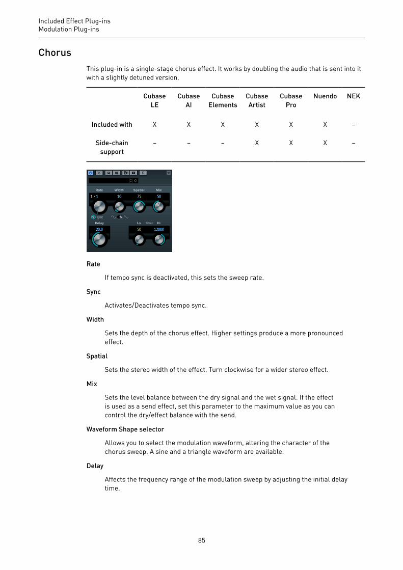
Included Effect Plug-insModulation Plug-ins
ChorusThis plug-in is a single-stage chorus effect. It works by doubling the audio that is sent into itwith a slightly detuned version.
CubaseLE
CubaseAI
CubaseElements
CubaseArtist
CubasePro
Nuendo NEK
Included with X X X X X X –
Side-chainsupport
– – – X X X –
Rate
If tempo sync is deactivated, this sets the sweep rate.
Sync
Activates/Deactivates tempo sync.
Width
Sets the depth of the chorus effect. Higher settings produce a more pronouncedeffect.
Spatial
Sets the stereo width of the effect. Turn clockwise for a wider stereo effect.
Mix
Sets the level balance between the dry signal and the wet signal. If the effectis used as a send effect, set this parameter to the maximum value as you cancontrol the dry/effect balance with the send.
Waveform Shape selector
Allows you to select the modulation waveform, altering the character of thechorus sweep. A sine and a triangle waveform are available.
Delay
Affects the frequency range of the modulation sweep by adjusting the initial delaytime.
85

Included Effect Plug-insModulation Plug-ins
Filter Lo/Hi
Allow you to roll off low and high frequencies of the effect signal.
NOTE
If side-chaining is supported, the modulation can also be controlled from another signalsource via the side-chain input. If the side-chain signal exceeds the threshold, themodulation is controlled by the side-chain signal’s envelope. For a description of how to setup side-chain routing, see the Operation Manual.
ClonerThis plug-in adds up to 4 detuned and delayed voices to the signal, for rich modulation andchorus effects.
CubaseLE
CubaseAI
CubaseElements
CubaseArtist
CubasePro
Nuendo NEK
Included with – – – – X X –
Voices
Sets the number of voices (up to 4). For each voice, a Detune and a Delay sliderare available in the right half of the panel.
Spatial
Spreads the voices across the stereo spectrum. Turn clockwise for a deeperstereo effect.
Mix
Sets the level balance between the dry signal and the wet signal. If the effectis used as a send effect, set this parameter to the maximum value as you cancontrol the dry/effect balance with the send.
Output (-12 to 12 dB)
Sets the output gain.
Detune slider (1 to 4)
Controls the relative detune amount for each voice. Positive and negative valuescan be set. A value of zero means no detune for that voice.
86

Included Effect Plug-insModulation Plug-ins
Delay slider (1 to 4)
Controls the relative delay amount for each voice. A value of zero means no delayfor that voice.
Natural
Changes the pitch algorithm.
Detune – Humanize
Controls the amount of detune variation if Static Detune is deactivated. WithHumanize, the detune is continuously modulated for a more natural effect.
Static Detune
Activate this button to use a static detune amount.
Delay
Governs the overall depth of the delay for all voices. If set to zero, no delay takesplace regardless of the Delay slider settings.
Delay – Humanize
Controls the amount of delay variation if Static Delay is deactivated. WithHumanize, the delay is continuously modulated for a more natural effect.
Static Delay
Activate this button to use a static delay amount.
FlangerThis is a classic flanger effect with added stereo enhancement.
CubaseLE
CubaseAI
CubaseElements
CubaseArtist
CubasePro
Nuendo NEK
Included with X X X X X X –
Side-chainsupport
– – – X X X –
87

Included Effect Plug-insModulation Plug-ins
Rate
If tempo sync is activated, this is where you specify the base note value forsynchronizing the flanger sweep to the tempo of the host application (1/1 to 1/32,straight, triplet, or dotted).
If tempo sync is deactivated, the sweep rate can be set freely with the Rate knob.
Sync
Activates/Deactivates tempo sync.
Range Lo/Hi
Set the frequency boundaries for the flanger sweep.
Feedback
Determines the character of the flanger effect. Higher settings produce a moremetallic sounding sweep.
Spatial
Sets the stereo width of the effect. Turn clockwise for a wider stereo effect.
Mix
Sets the level balance between the dry signal and the wet signal. If the effectis used as a send effect, set this parameter to the maximum value as you cancontrol the dry/effect balance with the send.
Waveform Shape selector
Allows you to select the modulation waveform, altering the character of theflanger sweep. A sine and a triangle waveform are available.
Delay
Affects the frequency range of the modulation sweep by adjusting the initial delaytime.
Manual
If this option is activated, the flanger sweep is static, that is, no modulation takesplace.
If the Manual button is deactivated, a knob is available, allowing you to changethe sweep position manually.
Filter Lo/Hi
Allow you to roll off low and high frequencies of the effect signal.
NOTE
If side-chaining is supported, the modulation can also be controlled from another signalsource via the side-chain input. If the side-chain signal exceeds the threshold, themodulation is controlled by the side-chain signal’s envelope. For a description of how to setup side-chain routing, see the Operation Manual.
88

Included Effect Plug-insModulation Plug-ins
MetalizerThis plug-in feeds the audio signal through a variable frequency filter, with tempo sync ortime modulation and feedback control.
CubaseLE
CubaseAI
CubaseElements
CubaseArtist
CubasePro
Nuendo NEK
Included with – X X X X X –
Feedback
Determines the character of the metal effect. Higher settings produce a moremetallic sound.
Sharpness
Governs the character of the filter effect. The higher the value, the narrowerthe affected frequency area, producing a sharper sound and a more pronouncedeffect.
Tone
Governs the feedback frequency. The effect of this is more noticeable with highFeedback settings.
On
Activates/Deactivates filter modulation. If it is deactivated, Metalizer works as astatic filter.
Mono
Switches the output to mono.
Speed
If tempo sync is activated, this is where you specify the base note value forsynchronizing the effect to the tempo of the host application (1/1 to 1/32, straight,triplet, or dotted).
If tempo sync is deactivated, the modulation speed can be set freely with theSpeed knob.
Sync
Activates/Deactivates tempo sync.
89
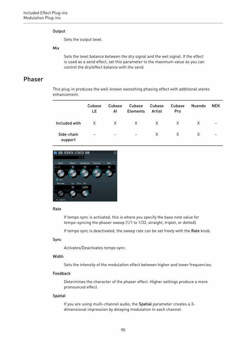
Included Effect Plug-insModulation Plug-ins
Output
Sets the output level.
Mix
Sets the level balance between the dry signal and the wet signal. If the effectis used as a send effect, set this parameter to the maximum value as you cancontrol the dry/effect balance with the send.
PhaserThis plug-in produces the well-known swooshing phasing effect with additional stereoenhancement.
CubaseLE
CubaseAI
CubaseElements
CubaseArtist
CubasePro
Nuendo NEK
Included with X X X X X X –
Side-chainsupport
– – – X X X –
Rate
If tempo sync is activated, this is where you specify the base note value fortempo-syncing the phaser sweep (1/1 to 1/32, straight, triplet, or dotted).
If tempo sync is deactivated, the sweep rate can be set freely with the Rate knob.
Sync
Activates/Deactivates tempo sync.
Width
Sets the intensity of the modulation effect between higher and lower frequencies.
Feedback
Determines the character of the phaser effect. Higher settings produce a morepronounced effect.
Spatial
If you are using multi-channel audio, the Spatial parameter creates a 3-dimensional impression by delaying modulation in each channel.
90

Included Effect Plug-insModulation Plug-ins
Mix
Sets the level balance between the dry signal and the wet signal. If the effectis used as a send effect, set this parameter to the maximum value as you cancontrol the dry/effect balance with the send.
Manual
If this option is activated, the flanger sweep is static, that is, no modulation takesplace.
If the Manual button is deactivated, a knob is available, allowing you to changethe sweep position manually.
Filter Lo/Hi
Allow you to roll off low and high frequencies of the effect signal.
NOTE
If side-chaining is supported, the modulation can also be controlled from another signalsource via the side-chain input. If the side-chain signal exceeds the threshold, themodulation is controlled by the side-chain signal’s envelope. For a description of how to setup side-chain routing, see the Operation Manual.
RingModulatorRingModulator can produce complex, bell-like enharmonic sounds.
CubaseLE
CubaseAI
CubaseElements
CubaseArtist
CubasePro
Nuendo NEK
Included with – X X X X X –
Ring modulators work by multiplying two audio signals. The ring modulated output containsadded frequencies generated by the sum of, and the difference between, the frequencies ofthe two signals.
RingModulator has a built-in oscillator that is multiplied with the input signal to produce theeffect.
91

Included Effect Plug-insModulation Plug-ins
OscillatorLFO Amount
Controls how much the oscillator frequency is affected by the LFO.
Env. Amount
Controls how much the oscillator frequency is affected by the envelope that istriggered by the input signal. Left of center, a loud input signal decreases theoscillator pitch, whereas right of center the oscillator pitch increases if it is fed aloud input.
Waveform buttons
Allow you to select the oscillator waveform: square, sine, saw, or triangle.
Range slider
Determines the frequency range of the oscillator in Hz.
Frequency
Sets the oscillator frequency ± 2 octaves within the selected range.
Roll-Off
Attenuates high frequencies in the oscillator waveform, to soften the overallsound. This is best used with harmonically rich waveforms (square or saw, forexample).
LFOSpeed
Sets the LFO speed.
Env. Amount
Controls how much the input signal level – via the envelope generator – affectsthe LFO speed. With negative values, a loud input signal slows down the LFO,whereas positive values speed it up at loud input signals.
Waveform
Allows you to select the LFO waveform: square, sine, saw, or triangle.
Invert Stereo
Inverts the LFO waveform for the right channel of the oscillator, which produces awider stereo effect for the modulation.
Envelope GeneratorThe Envelope Generator section controls how the input signal is converted to envelope data,which can then be used to control oscillator pitch and LFO speed.
Attack
Controls how fast the envelope output level rises in response to a rising inputsignal.
92

Included Effect Plug-insModulation Plug-ins
Decay
Controls how fast the envelope output level falls in response to a falling inputsignal.
Lock L<R
If this button is activated, the L and R input signals are merged, and producethe same envelope output level for both oscillator channels. If the button isdeactivated, each channel has its own envelope that affects the two channels ofthe oscillator independently.
Final SettingsOutput
Sets the output level.
Mix
Sets the level balance between the dry signal and the wet signal.
RotaryThis modulation effect simulates the classic effect of a rotating speaker.
CubaseLE
CubaseAI
CubaseElements
CubaseArtist
CubasePro
Nuendo NEK
Included with – – X X X X –
A rotary speaker cabinet features speakers rotating at variable speeds to produce a swirlingchorus effect, commonly used with organs.
SpeedSpeed selector (stop/slow/fast)
Allows you to control the speed of the Rotary in three steps.
Speed Change Mode
If this is set to the left, the speed selector settings are taken into account. If thisis set to the right, you can modulate the speed with the Speed Mod knob and/orwith a MIDI controller that you can select on the Speed Mod Control (MIDI) pop-up menu.
93

Included Effect Plug-insModulation Plug-ins
Speed Mod
If the Speed Change Mode setting is set to the right side, this knob allows you tomodulate the rotary speed.
Speed Mod Control (MIDI)
This pop-up menu allows you to select the MIDI controller that controls theRotary speed. If you do not want to use MIDI realtime control, set this toAutomation. If you select Pitchbend as MIDI controller, the speed changes withan up or down flick of the bender. If other MIDI controllers are used, the speedchanges at MIDI value 64.
Additional settingsOverdrive
Applies a soft overdrive or distortion.
CrossOver
Sets the crossover frequency (200 to 3000 Hz) between the low and highfrequency loudspeakers.
HornSlow
Allows for a fine adjustment of the high rotor slow speed.
Fast
Allows for a fine adjustment of the high rotor fast speed.
Accel.
Allows for a fine adjustment of the high rotor acceleration time.
Amp Mod
Controls the high rotor amplitude modulation.
Freq Mod
Controls the high rotor frequency modulation.
BassSlow
Allows for a fine adjustment of the low rotor slow speed.
Fast
Allows for a fine adjustment of the low rotor fast speed.
Accel.
Allows for a fine adjustment of the low rotor acceleration time.
Amp Mod
Adjusts the modulation depth of the amplitude.
94

Included Effect Plug-insModulation Plug-ins
Level
Adjusts the overall bass level.
MicrophonesPhase
Adjusts the phasing amount in the sound of the high rotor.
Angle
Sets the simulated microphone angle. 0 = mono, 180 = a mic on each side.
Distance
Sets the simulated microphone distance from the speaker in inches.
Final SettingsOutput
Sets the output level.
Mix
Sets the level balance between the dry signal and the wet signal.
Directing MIDI to the RotaryFor realtime MIDI control of the speed parameter, MIDI must be directed to the Rotary.
• If Rotary is used as insert effect (for an audio track or an FX channel), it is available onthe Output Routing pop-up menu for MIDI tracks. If Rotary is selected on the OutputRouting pop-up menu, MIDI is directed to the plug-in from the selected track.
StudioChorusStudioChorus is a two-stage chorus effect that adds short delays to the signal and modulatesthe pitch of the delayed signals to produce a doubling effect. The two separate stages ofchorus modulation are independent and are processed serially (cascaded).
CubaseLE
CubaseAI
CubaseElements
CubaseArtist
CubasePro
Nuendo NEK
Included with – – – – X X –
Side-chainsupport
– – – – X X –
95
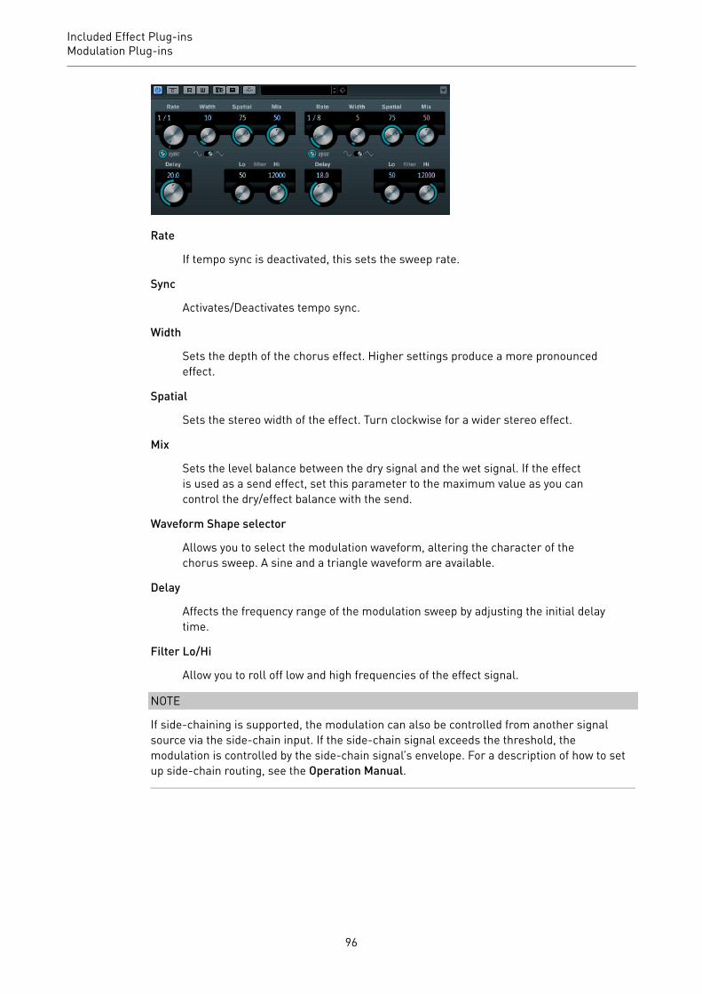
Included Effect Plug-insModulation Plug-ins
Rate
If tempo sync is deactivated, this sets the sweep rate.
Sync
Activates/Deactivates tempo sync.
Width
Sets the depth of the chorus effect. Higher settings produce a more pronouncedeffect.
Spatial
Sets the stereo width of the effect. Turn clockwise for a wider stereo effect.
Mix
Sets the level balance between the dry signal and the wet signal. If the effectis used as a send effect, set this parameter to the maximum value as you cancontrol the dry/effect balance with the send.
Waveform Shape selector
Allows you to select the modulation waveform, altering the character of thechorus sweep. A sine and a triangle waveform are available.
Delay
Affects the frequency range of the modulation sweep by adjusting the initial delaytime.
Filter Lo/Hi
Allow you to roll off low and high frequencies of the effect signal.
NOTE
If side-chaining is supported, the modulation can also be controlled from another signalsource via the side-chain input. If the side-chain signal exceeds the threshold, themodulation is controlled by the side-chain signal’s envelope. For a description of how to setup side-chain routing, see the Operation Manual.
96

Included Effect Plug-insModulation Plug-ins
TranceformerIn this ring modulator effect, the incoming audio is ring modulated by an internal, variablefrequency oscillator, producing new harmonics. A second oscillator can be used to modulatethe frequency of the first oscillator, in sync with the Song tempo if needed.
CubaseLE
CubaseAI
CubaseElements
CubaseArtist
CubasePro
Nuendo NEK
Included with – X X X X X –
Waveform
These buttons allow you to select a pitch modulation waveform.
Tone
Sets the frequency (pitch) of the modulating oscillator.
Depth
Sets the intensity of the pitch modulation.
NOTE
Clicking and dragging in the display allows you to adjust Tone and Depth at the same time.
Speed
If tempo sync is activated, this is where you specify the base note value forsynchronizing the effect to the tempo of the host application (1/1 to 1/32, straight,triplet, or dotted).
If tempo sync is deactivated, the modulation speed can be set freely with theSpeed knob.
Sync
The button above the Speed knob activates/deactivates tempo sync.
On
Activates/Deactivates the modulation of the pitch parameter.
Mono
Switches the output to mono.
97

Included Effect Plug-insModulation Plug-ins
Output
Sets the output level.
Mix
Sets the level balance between the dry signal and the wet signal.
TremoloTremolo produces amplitude modulation.
CubaseLE
CubaseAI
CubaseElements
CubaseArtist
CubasePro
Nuendo NEK
Included with X X X X X X –
Side-chainsupport
– – – X X X –
Rate
If tempo sync is activated, this is where you specify the base note value fortempo-syncing the effect (1/1 to 1/32, straight, triplet, or dotted).
If tempo sync is deactivated, the modulation speed can be set freely with the Rateknob.
Sync
Activates/Deactivates tempo sync.
Depth
Governs the depth of the amplitude modulation.
Spatial
Adds a stereo effect to the modulation.
Output
Sets the output level.
NOTE
If side-chaining is supported, the modulation can also be controlled from another signalsource via the side-chain input. If the side-chain signal exceeds the threshold, themodulation is controlled by the side-chain signal’s envelope. For a description of how to setup side-chain routing, see the Operation Manual.
98
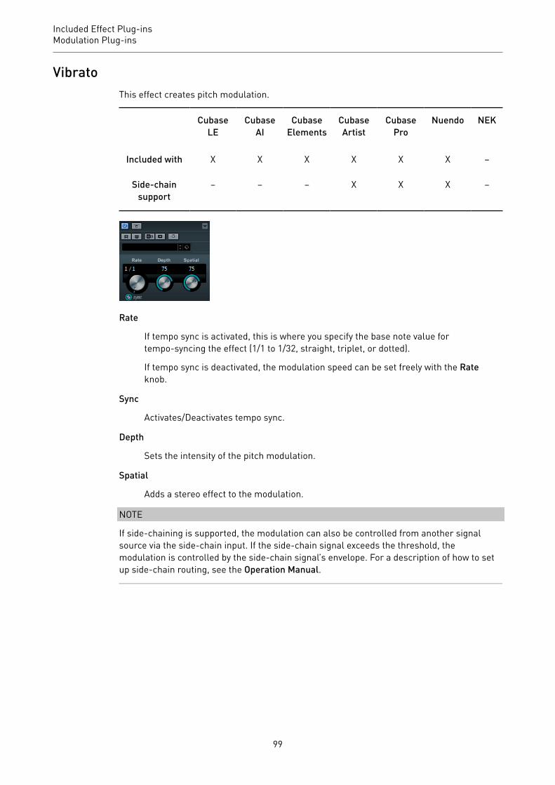
Included Effect Plug-insModulation Plug-ins
VibratoThis effect creates pitch modulation.
CubaseLE
CubaseAI
CubaseElements
CubaseArtist
CubasePro
Nuendo NEK
Included with X X X X X X –
Side-chainsupport
– – – X X X –
Rate
If tempo sync is activated, this is where you specify the base note value fortempo-syncing the effect (1/1 to 1/32, straight, triplet, or dotted).
If tempo sync is deactivated, the modulation speed can be set freely with the Rateknob.
Sync
Activates/Deactivates tempo sync.
Depth
Sets the intensity of the pitch modulation.
Spatial
Adds a stereo effect to the modulation.
NOTE
If side-chaining is supported, the modulation can also be controlled from another signalsource via the side-chain input. If the side-chain signal exceeds the threshold, themodulation is controlled by the side-chain signal’s envelope. For a description of how to setup side-chain routing, see the Operation Manual.
99

Included Effect Plug-insOther Plug-ins
Other Plug-ins
LoopMash FXLoopMash FX is a live performance effect offering DJ effects that can be controlled by a MIDIkeyboard.
CubaseLE
CubaseAI
CubaseElements
CubaseArtist
CubasePro
Nuendo NEK
Included with – – – X X X –
Quantize Note
Sets the note value on which the quantize grid of the effects is based.
Performance ControlsBy clicking these buttons during playback, you can apply effects to your overall performance.
An effect is applied as long as you keep the button pressed.
NOTE
The effects can be automated. The automation of effect parameters is described in theOperation Manual.
Backspin
Simulates a turntable backspin.
100

Included Effect Plug-insOther Plug-ins
Reverse
Plays the slice in reverse.
Tapestart
Simulates a tapestart, that is, speeds the slice up.
Scratch
Plays the slice as if scratched.
Slowdown
Applies a slowdown.
Tapestop 1
Simulates a tapestop, that is, slows the slice down, first lightly then abruptly.
Tapestop 2
Simulates a tapestop, that is, slows the slice down, smoothly.
Stutter
Plays only the initial portion of a slice and repeats it 2, 3, 4, 6, or 8 times duringone slice length.
Slur
Stretches the slice over 2 or 4 slice lengths.
Cycle
Sets up a short cycle over 4, 2, or 1 slice. This short cycle is always set up withinthe loop range that is set in the ruler. Setting up a cycle over 1 slice means thatthis slice is repeated until you release the button.
Staccato
101

Included Effect Plug-insOther Plug-ins
Shortens the slice.
Mute
Mutes the slice.
Triggering the Performance Controls with Your MIDI KeyboardYou can trigger the performance controls with your MIDI keyboard starting from C3upwards. You can also use the virtual keyboard for triggering the performance controls (forinformation about the virtual keyboard see the Operation Manual).
Controlling LoopMash FX with a MIDI Keyboard
PROCEDURE1. Create an audio track and import an audio file, a drum loop, for example.2. Insert LoopMash FX as an insert effect.3. Play back the drum loop in a cycle.4. Create a MIDI track.5. On the Output Routing pop-up menu for the MIDI track, select LoopMash FX.
RESULT
You can trigger the different LoopMash FX performance effects with a MIDI keyboard.
VST Connect CUE Mix
CubaseLE
CubaseAI
CubaseElements
CubaseArtist
CubasePro
Nuendo NEK
Included with – – – – X X –
This plug-in is described in detail in the separate PDF document VST Connect SE.
VST Connect SE
CubaseLE
CubaseAI
CubaseElements
CubaseArtist
CubasePro
Nuendo NEK
Included with – – – – X X –
This plug-in is described in detail in the separate PDF document VST Connect SE.
102

Included Effect Plug-insPitch Shift Plug-ins
Pitch Shift Plug-ins
OctaverThis plug-in can generate two additional voices that track the pitch of the input signal oneoctave and two octaves below the original pitch. Octaver is best used with monophonicsignals.
CubaseLE
CubaseAI
CubaseElements
CubaseArtist
CubasePro
Nuendo NEK
Included with – X X X X X –
Direct
Sets the level balance between the dry signal and the wet signal. A value of 0means that only the generated and transposed signal is heard. By raising thisvalue, more of the original signal is heard.
Octave 1
Adjusts the level of the generated signal one octave below the original pitch. Asetting of 0 means that the voice is muted.
Octave 2
Adjusts the level of the generated signal two octaves below the original pitch. Asetting of 0 means that the voice is muted.
Pitch CorrectPitch Correct automatically detects, adjusts, and fixes slight pitch and intonationinconsistencies in monophonic vocal and instrumental performances in realtime. Theadvanced algorithms preserve the formants of the original sound and allow for naturalsounding pitch correction without the typical Mickey Mouse effect.
CubaseLE
CubaseAI
CubaseElements
CubaseArtist
CubasePro
Nuendo NEK
Included with – – X X X X –
103

Included Effect Plug-insPitch Shift Plug-ins
You can use Pitch Correct creatively. You can create backing vocals, for example, bymodifying the lead vocals or vocoder sounds by using extreme values. You can use anexternal MIDI controller, a MIDI track, or the virtual keyboard to play a note or a scale oftarget pitches that determine the current scale notes to which the audio is shifted. Thisallows you to change your audio in a very quick and easy way, which is extremely useful forlive performances. In the keyboard display, the original audio is displayed in blue while thechanges are displayed in orange.
CorrectionSpeed
Determines the smoothness of the pitch change. Higher values cause the pitchshift to occur immediately. 100 is a very drastic setting that is designed mainly forspecial effects.
Tolerance
Determines the sensitivity of analysis. A low Tolerance value lets Pitch Correctfind pitch changes quickly. If the Tolerance value is high, pitch variations in theaudio (for example, vibrato) are not immediately interpreted as note changes.
Transpose
With this parameter you can adjust, or retune, the pitch of the incoming audio insemitone steps. A value of zero means that the signal is not transposed.
Scale sourceInternal
If you choose the Internal option from the Scale Source pop-up menu, you canuse the pop-up menu next to it to decide to which scale the source audio isadapted.
• Chromatic: The audio is pitched to the closest semitone.• Major/Minor: The audio is pitched to the major/minor scale specified on
the pop-up menu to the right. This is reflected on the keyboard display.
104
Included Effect Plug-insPitch Shift Plug-ins
• Custom: The audio is pitched to the notes that you specify by clicking keyson the keyboard display. To reset the keyboard, click the orange line belowthe display.
External MIDI Scale
Select this option if you want the audio to be shifted to a scale of target pitches,using an external MIDI controller, the virtual keyboard, or a MIDI track.
NOTE
You have to assign the audio track as the output of your MIDI track and the Speedparameter has to be set to a value other than Off.
External MIDI Note
Select this option if you want the audio to be shifted to a target note, using anexternal MIDI controller, the Virtual Keyboard or a MIDI track.
NOTE
You have to assign the audio track as the output of your MIDI track and the Speedparameter has to be set to a value other than Off.
Chord Track – Chords
Select this option if you want the audio to be shifted to target chords, using thechord information from the Chord track.
NOTE
You have to add a MIDI track in addition to the Chord track and assign PitchCorrect as output of the MIDI track.
Chord Track – Scale
Select this option if you want the audio to be shifted to a scale of target pitches,using the scale information from the Chord track.
NOTE
You have to add a MIDI track in addition to the Chord track and assign PitchCorrect as output of the MIDI track.
FormantShift
Changes the natural timbre, that is, the characteristic frequency components ofthe source audio.
Optimize (General, Male, Female)
Allows you to specify the sound characteristics of the sound sources. General isthe default setting, Male is designed for low pitches and Female for high pitches.
105

Included Effect Plug-insPitch Shift Plug-ins
Preservation (On/Off)
If this parameter is set to Off, formants are raised and lowered with the pitch,provoking strange vocal effects. Higher pitch correction values result in MickeyMouse effects, lower pitch correction values in Monster sounds. If this parameteris set to On, the formants are kept, maintaining the character of the audio.
Master Tuning
Detunes the output signal.
PitchDriverThis effect allows for sound design in postproduction. It can be used for extreme up or downpitching of voices or effect samples (for example, to create eerie monster sounds). Shiftingthe pitch with this plug-in does not keep the formants.
CubaseLE
CubaseAI
CubaseElements
CubaseArtist
CubasePro
Nuendo NEK
Included with – – – – – X –
Detune
Lets you detune the pitch of the incoming audio.
Mix
Sets the level balance between the dry signal and the wet signal.
Spatial
Creates an ambience effect. It introduces a light pitch offset to the incomingsignal. Different offset values are used for the individual input channels in orderto create a panorama effect.
NOTE
The created panorama effect can be unstable. For a stable panorama, deactivatethe Spatial parameter. Then, the incoming signals are summed up to a monosignal.
Output
Sets the output level.
106

Included Effect Plug-insReverb Plug-ins
To avoid hearing artifacts, it is recommended to set the ASIO buffer for your audio card to atleast 128 samples. The buffer size can be set on the control panel for the card (opened viathe Device Setup dialog).
Reverb Plug-ins
REVelationThis effect produces a high-quality algorithmic reverb with early reflections and reverb tail.
CubaseLE
CubaseAI
CubaseElements
CubaseArtist
Cubase Nuendo NEK
Included with – – – X X X –
The early reflections are responsible for the spatial impression in the first milliseconds ofthe reverb. For emulating different rooms, you can choose between different early reflectionspatterns and adjust their size. The reverb tail, or late reverberation, offers parameters forcontrolling the room size and the reverb time. You can adjust the reverb time individually in 3frequency bands.
Pre-Delay
Determines how much time passes before the reverb is applied. This allows youto simulate larger rooms by increasing the time it takes for the first reflections toreach the listener.
Early Reflections
Here, you select an early reflections pattern. The early reflections patterncontains the most important delays that deliver the key information for thespatial impression of the room.
107

Included Effect Plug-insReverb Plug-ins
ER/Tail Mix
Sets the level balance between the early reflections and the reverb tail. At asetting of 50 %, early reflections and tail have the same volume. Settings below50 % raise the early reflections and lower the tail, as a result the sound sourcemoves towards the front of the room. Settings above 50 % raise the tail and lowerthe early reflections, as a result the sound source moves towards the back of theroom.
Size
Adjusts the length of the early reflections pattern. At a setting of 100 %, thepattern is applied with its original length and the room sounds the most natural.At settings below 100 %, the early reflections pattern is compressed and the roomis perceived smaller.
Low Cut
Attenuates the low frequencies of the early reflections. The higher this value, theless low frequencies are present in the early reflections.
High Cut
Attenuates the high frequencies of the early reflections. The lower this value, theless high frequencies the early reflections will have.
Delay
Delays the onset of the reverb tail.
Room Size
Controls the dimensions of the simulated room. At a setting of 100 %, thedimensions correspond to a cathedral or a large concert hall. At a setting of 50 %,the dimensions correspond to a medium-sized room or studio. Settings below 50 % simulate the dimensions of small rooms or a booth.
Main Time
Controls the overall reverb time of the tail. The higher this value, the longer thereverb tail will decay. At a setting of 100 %, the reverb time is infinitely long. TheMain Time parameter also represents the mid band of the reverb tail.
High Time
Controls the reverb time for the high frequencies of the reverb tail. With positivevalues, the decay time of the high frequencies is longer. With negative values, it isshorter. Frequencies are affected depending on the High Freq parameter.
Low Time
Controls the reverb time for the low frequencies of the reverb tail. For positivevalues, low frequencies decay longer and vice versa. Frequencies will be affecteddepending on the Low Freq parameter.
High Freq
Sets the cross-over frequency between the mid and the high band of the reverbtail. You can offset the reverb time for frequencies above this value from the mainreverb time with the High Time parameter.
108
Included Effect Plug-insReverb Plug-ins
Low Freq
Sets the cross-over frequency between the low and the mid band of the reverbtail. The reverb time for frequencies below this value can be offset from the mainreverb time with the Low Time parameter.
Shape
Controls the attack of the reverb tail. At a setting of 0 %, the attack is moreimmediate, which is a good setting for drums. The higher this value, the lessimmediate the attack.
Density
Adjusts the echo density of the reverb tail. At a setting of 100 %, single reflectionsfrom walls cannot be heard. The lower this value, the more single reflections canbe heard.
High Cut
Attenuates the high frequencies of the reverb tail. The lower this value, the lesshigh frequencies the reverb tail will have.
Width
Adjusts the output of the reverb signal between mono and stereo. At a setting of 0 %, the output of the reverb is mono, at 100 % it is stereo.
Mix
Sets the level balance between the dry signal and the wet signal. If the effectis used as a send effect, set this parameter to the maximum value as you cancontrol the dry/effect balance with the send.
Lock
Activate this button (padlock symbol) next to the Mix parameter to lock the dry/wet balance while browsing through the available presets.
ModulationModulation allows you to enrich the reverb tail through subtle pitch modulations.
Modulation Enable
Activates/Deactivates the chorusing effect.
Modulation Rate
Specifies the frequency of the pitch modulation.
Modulation Depth
Sets the intensity of the pitch modulation.
109

Included Effect Plug-insReverb Plug-ins
REVerenceREVerence is a convolution tool that allows you to apply room characteristics (reverb) to theaudio.
CubaseLE
CubaseAI
CubaseElements
CubaseArtist
CubasePro
Nuendo NEK
Included with – – – – X X –
This is done by processing the audio signal according to an impulse response – a recordingof an impulse in a room or another location that recreates the characteristics of the room. Asa result, the processed audio sounds as if it were played in the same location. Included withthe plug-in are top quality samples of real spaces to create reverberation.
NOTE
REVerence can be very demanding in terms of RAM. This is because the impulse responsesthat you load into the program slots are preloaded into RAM to guarantee artifact-freeswitching between programs. Therefore, you should always load only those programs thatyou need for a given task.
Program MatrixA program is the combination of an impulse response and its settings. These include reverbsettings, EQ settings, pictures, and output settings. The program matrix allows you to loadprograms or to view the name of the impulse response.
110
Included Effect Plug-insReverb Plug-ins
Program name
In the upper left corner of the plug-in panel, either the name of the loadedimpulse response file or the name of the program is shown. After loadingan impulse response, its number of channels and the length in seconds aredisplayed for a few seconds.
Browse
This button opens a browser window showing the available programs. If youselect a program in the browser, it is loaded into the active program slot. Tofilter the list of impulse responses by room type or the number of channels,for example, activate the Filters section (by clicking the Set Up Window Layoutbutton at the bottom left of the window).
Import
Click this button to load your own impulse response files from disk. The filesshould have a maximum length of 10 seconds. Longer files are automatically cut.
Program slots
Use these slots to load all the impulse responses that you want to work with ina session. The selected program slot is indicated by a white frame. Used slotsare shown in a different color. Double-clicking an empty program slot opens abrowser window, showing the available programs. Clicking a used program slotrecalls the corresponding program and loads it into REVerence. If you move themouse over a used slot, the corresponding program name is displayed below theactive program name.
Smooth Parameter Changes
This button is located between the program slots and the Store/Erase buttons.If it is activated, a crossfade is performed when switching programs. Leave thisbutton deactivated while looking for a suitable program or an appropriate settingfor an impulse response. Once you have set up the program matrix to your liking,activate the button to avoid hearing artifacts when switching between programs.
Store
Stores the active impulse response and its settings as a program.
Erase
Removes the selected program from the matrix.
Programs vs. PresetsYou can save your REVerence settings as VST plug-in presets or programs. Both presetsand programs use the file extension .vstpreset and appear in the same category in theMediaBay, but they are represented by different icons.
Preset
A REVerence preset contains all settings and parameters for the plug-in, that is,all loaded impulse responses along with their parameter settings and positionsin the program matrix. Presets are loaded via the Presets pop-up menu at the topof the plug-in panel.
111
Included Effect Plug-insReverb Plug-ins
Program
A REVerence program only contains the settings related to a single impulseresponse. Programs are loaded and managed via the program matrix.
PresetsPresets are useful in the following situations:
• To save a complete setup with different impulse responses for later use (for example,different setups for explosion sounds that can be reused for other scenes or movies).
• When you want to save different parameter sets for the same impulse response so thatyou can later choose the set that best suits your needs.
ProgramsPrograms offer the following advantages:
• Up to 36 programs can be loaded into the program matrix for instant recall.• A program provides a quick and easy way to save and recall the settings for a single
impulse response, allowing for short loading times.• When automating a project and loading a REVerence program, only one automation
event is written.If you load a plug-in preset instead (which contains a lot more settings than aprogram), a lot of unnecessary automation data (for the settings that you did not use) iswritten.
RELATED LINKSReverb Settings on page 113EQ Settings on page 115The Pictures Section on page 116Custom Impulse Responses on page 117
Setting up Programs
PROCEDURE1. In the program matrix, click on a program slot to select it.
A blinking white frame indicates that this program slot is selected.
2. Click the Browse button or click the empty slot again to load one of the includedprograms.You can also import a new impulse response file.
3. In the browser, select the program containing the impulse response that you want touse and click OK.The name of the loaded impulse response is shown in the upper left corner of theREVerence panel.
4. Set up the REVerence parameters as and click the Store button to save the impulseresponse with the current settings as a new program.
5. Set up as many programs as you need by following the steps above.
112

Included Effect Plug-insReverb Plug-ins
NOTEIf you want to use your set of programs in other projects, save your settings as a plug-in preset.
RELATED LINKSImporting Impulse Responses on page 117
Reverb SettingsThe reverb settings allow you to change the characteristics of the room.
Main
All values shown in the top row apply to all speakers or to the front channels ifyou are working with surround tracks.
Rear
If you are working with surround tracks up to 5.1, you can use this row to set upan offset for the rear channels.
Auto Gain
If this button is activated, the impulse response is automatically normalized.
Reverse
Reverses the impulse response.
Pre-Delay
Determines how much time passes before the reverb is applied. This allows youto simulate larger rooms by increasing the time it takes for the first reflections toreach the listener.
Time Scaling
Controls the reverb time.
Size
Determines the size of the simulated room.
Level
A level control for the impulse response. This governs the volume of the reverb.
ER Tail Split
Sets a split point between the early reflections and the tail, allowing you todetermine where the reverb tail begins. A value of 60 means that the earlyreflections are heard for 60 ms.
113

Included Effect Plug-insReverb Plug-ins
ER Tail Mix
Allows you to set up the relation of early reflections and tail. Values above 50attenuate the early reflections and values below 50 attenuate the tail.
The Impulse Response DisplayThe display section allows you to view the impulse response details and to change the lengthof the response.
Play
When clicking this button to apply the loaded impulse response, a short click isplayed. This provides a neutral test sound that makes it easier for you to knowhow different settings influence the reverb characteristics.
Time Scaling
This wheel lets you adjust the reverb time.
Time Domain
This display shows the waveform of the impulse response.
Spectrogram
This display shows the analyzed spectrum of the impulse response. Time isdisplayed along the horizontal axis, frequency along the vertical axis, and volumeis represented by the color.
Information
This display shows additional information, such as the name of the program andthe loaded impulse response, the number of channels, the length, and BroadcastWave File information.
Activate Impulse Trimming
Use this button at the bottom right of the impulse display section to activateimpulse trimming. The Trim slider is shown below the Impulse display.
Trim
This slider allows you to trim the start and end of the impulse response. Drag thefront handle to trim the start of the impulse response, and the end handle to trimthe reverb tail.
114
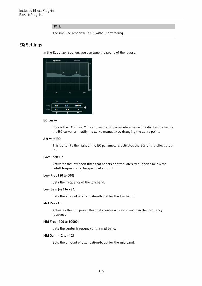
Included Effect Plug-insReverb Plug-ins
NOTE
The impulse response is cut without any fading.
EQ SettingsIn the Equalizer section, you can tune the sound of the reverb.
EQ curve
Shows the EQ curve. You can use the EQ parameters below the display to changethe EQ curve, or modify the curve manually by dragging the curve points.
Activate EQ
This button to the right of the EQ parameters activates the EQ for the effect plug-in.
Low Shelf On
Activates the low shelf filter that boosts or attenuates frequencies below thecutoff frequency by the specified amount.
Low Freq (20 to 500)
Sets the frequency of the low band.
Low Gain (-24 to +24)
Sets the amount of attenuation/boost for the low band.
Mid Peak On
Activates the mid peak filter that creates a peak or notch in the frequencyresponse.
Mid Freq (100 to 10000)
Sets the center frequency of the mid band.
Mid Gain(-12 to +12)
Sets the amount of attenuation/boost for the mid band.
115

Included Effect Plug-insReverb Plug-ins
Hi Shelf On
Activates the high shelf filter that boosts or attenuates frequencies above thecutoff frequency by the specified amount.
Hi Freq (5000 to 20000)
Sets the frequency of the high band.
Hi Gain (-24 to +24)
Sets the amount of attenuation/boost for the high band.
The Pictures SectionIn the Pictures section, you can load graphics files to illustrate the setting, for example, therecording location or microphone arrangement of the loaded impulse response. Up to fivepictures can be loaded.
NOTE
Pictures are only referenced by the plug-in and are not copied to the project folder.
Add
Opens a file dialog where you can navigate to the graphics file that you want toimport. JPG, GIF, and PNG file formats are supported.
Next
If several pictures are loaded, you can click this button to display the next image.
Remove
Deletes the active picture.
NOTE
This does not remove the graphics file from your hard disk.
116
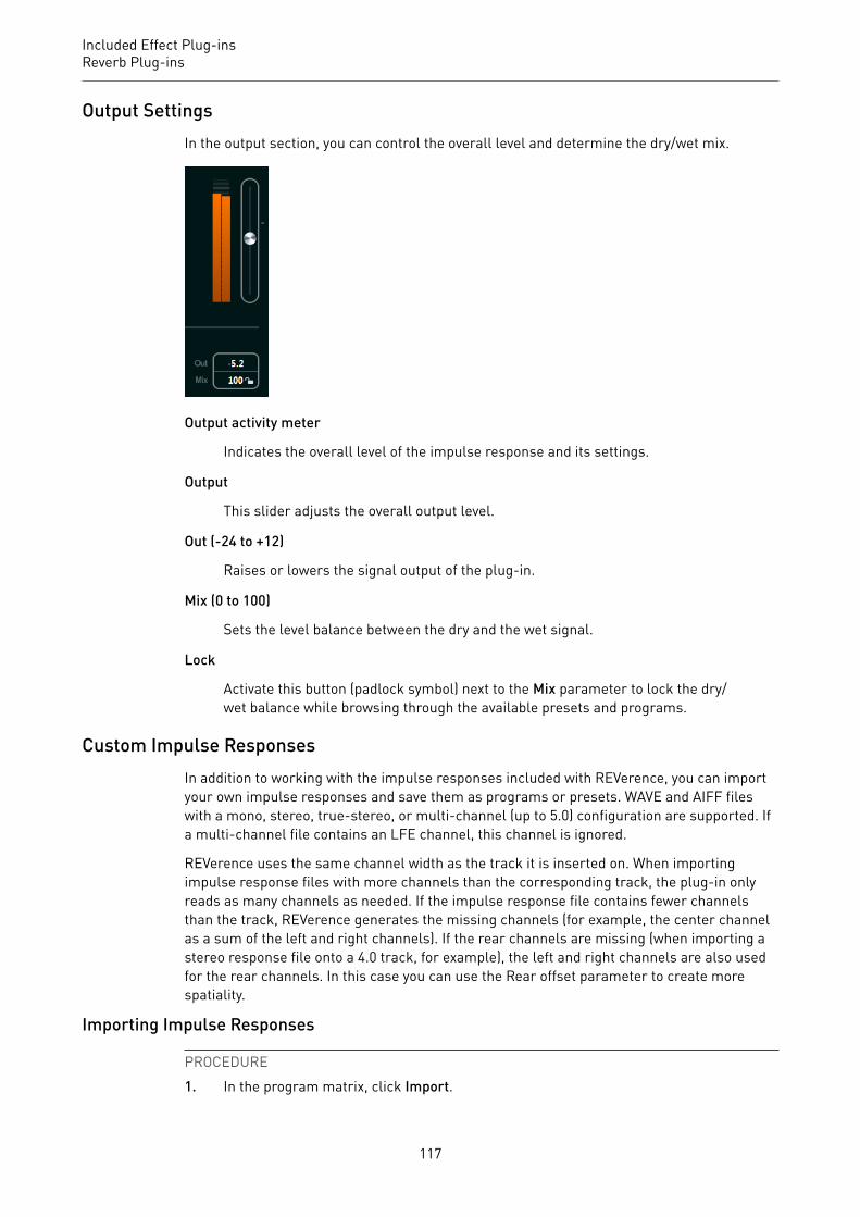
Included Effect Plug-insReverb Plug-ins
Output SettingsIn the output section, you can control the overall level and determine the dry/wet mix.
Output activity meter
Indicates the overall level of the impulse response and its settings.
Output
This slider adjusts the overall output level.
Out (-24 to +12)
Raises or lowers the signal output of the plug-in.
Mix (0 to 100)
Sets the level balance between the dry and the wet signal.
Lock
Activate this button (padlock symbol) next to the Mix parameter to lock the dry/wet balance while browsing through the available presets and programs.
Custom Impulse ResponsesIn addition to working with the impulse responses included with REVerence, you can importyour own impulse responses and save them as programs or presets. WAVE and AIFF fileswith a mono, stereo, true-stereo, or multi-channel (up to 5.0) configuration are supported. Ifa multi-channel file contains an LFE channel, this channel is ignored.
REVerence uses the same channel width as the track it is inserted on. When importingimpulse response files with more channels than the corresponding track, the plug-in onlyreads as many channels as needed. If the impulse response file contains fewer channelsthan the track, REVerence generates the missing channels (for example, the center channelas a sum of the left and right channels). If the rear channels are missing (when importing astereo response file onto a 4.0 track, for example), the left and right channels are also usedfor the rear channels. In this case you can use the Rear offset parameter to create morespatiality.
Importing Impulse Responses
PROCEDURE1. In the program matrix, click Import.
117
Included Effect Plug-insReverb Plug-ins
2. Navigate to the file that you want to import, and click Open.The file is loaded into REVerence. The channels from an interleaved file are importedin the same order as in other areas of the program (for example, the VST Connectionswindow), see below.
3. Make the appropriate settings and add a picture, if available.Pictures residing in the same folder as the impulse response file or in the parentfolder are automatically found and displayed.
4. Click the Store button to save the impulse response and its settings as a program.That way you can recall the setup at any time.
RESULT
The program slot turns blue, indicating that a program is loaded.
NOTE
When saving a program, the impulse response file itself is only referenced. It still resides inthe same location as before and is not modified in any way.
AFTER COMPLETING THIS TASK
Repeat these steps for any impulse response files that you want to work with.
Reading Order of Input ChannelsREVerence reads input channels in the following order.
Number ofinput channels
Channel order in REVerence
1 L
2 L/R
3 L/R/C
4 L/R/LS/RS (if inserted on a track with a 4.0 channel configuration)
4 LL/LR/RL/RR (if inserted on a track with a stereo configuration)
5 L/R/C/LS/RS
6 L/R/C/LFE/LS/RS (LFE is being ignored.)
True StereoImpulse responses recorded as true-stereo files allow you to create a very realisticimpression of the corresponding room.
REVerence can only process true-stereo impulse response files with the following channelconfiguration (in exactly that order): LL, LR, RL, RR.
The channels are defined as follows:
118
Included Effect Plug-insReverb Plug-ins
Channel The signal from this source… …was recorded withthis microphone
LL left source left microphone
LR left source right microphone
RL right source left microphone
RR right source right microphone
NOTE
If your true-stereo impulse responses are only available as separate mono files, you can usethe Export Audio Mixdown function to create REVerence compliant interleaved files (see theOperation Manual).
REVerence automatically works in true-stereo mode if the plug-in is inserted on a stereotrack and you load a 4-channel impulse response.
Therefore, if you are working with surround files, that is, 4-channel impulse responsesrecorded with a Quadro configuration (L/R, LS/RS), you need to insert the plug-in on an audiotrack with a 4.0 configuration. On a stereo track, these files would be processed in true-stereo mode, too.
So how can you prevent REVerence from unintentionally processing surround files in true-stereo mode? The answer is a Recording Method attribute that can be written to the iXMLchunk of the corresponding impulse response file. Whenever you load an impulse responsewith a 4-channel configuration on a stereo track, REVerence searches the iXML chunk of thefile. If the plug-in finds the Recording Method attribute, the following happens:
• If the attribute is set to TrueStereo, the plug-in works in true-stereo mode.• If the attribute is set to A/B or Quadro, the plug-in works in normal stereo mode and
processes only the L/R channels of the surround file.
NOTE
You can use the Attribute Inspector in the MediaBay to tag your own impulse response fileswith the Recording Method attribute. For more information, see the Operation Manual.
Relocating ContentOnce you have imported your own impulse responses to REVerence, you can comfortablywork with them on your computer. But what if you need to transfer your content to anothercomputer, for example, because you work sometimes with a PC and sometimes with anotebook, or you need to hand over a project to a colleague in the studio?
The factory content is not a problem because it is also present on the other computer. Forthese impulse responses, you just need to transfer your REVerence programs and presets tobe able to access your setups.
User content is a different matter, though. If you have transferred your audio files to anexternal drive or a different hard disk location on the other computer, REVerence cannotaccess the impulse responses any more because the old file paths have become invalid.
119

Included Effect Plug-insReverb Plug-ins
PROCEDURE1. Transfer you audio files to a location that you can access from the second computer
(for example, an external hard disk).If you keep the files in the same folder structure as on the first computer, REVerenceautomatically finds all files contained in this structure.
2. Transfer any REVerence presets or programs that you need to the second computer.If you are unsure where the presets need to be stored, you can find the paths in theMediaBay (see the Operation Manual).
3. Open REVerence on the second computer and try to load the preset or program thatyou want to work with.The Locate Impulse Response dialog opens.
4. Navigate to the folder that contains your impulse responses.5. Click Open.
RESULT
REVerence is now able to access all the impulse responses stored in this location.
IMPORTANT
The new path to these audio files has not been saved yet. To make the files permanentlyavailable without having to use the locate dialog, you need to save your programs or presetsunder a different name.
RoomWorksRoomWorks is a highly adjustable reverb plug-in for creating realistic room ambience andreverb effects in stereo and surround formats. The CPU usage is adjustable to fit the needsof any system. From short room reflections to cavern-sized reverb, this plug-in delivers highquality reverberation.
CubaseLE
CubaseAI
CubaseElements
CubaseArtist
CubasePro
Nuendo NEK
Included with – – – – X X –
120
Included Effect Plug-insReverb Plug-ins
Input FiltersLo Freq
Determines the frequency at which the low-shelving filter takes effect. Both thehigh and low settings filter the input signal prior to reverb processing.
Hi Freq
Determines the frequency at which the high-shelving filter takes effect. Both thehigh and low settings filter the input signal prior to reverb processing.
Lo Gain
Sets the amount of boost or attenuation for the low-shelving filter.
Hi Gain
Sets the amount of boost or attenuation for the high-shelving filter.
Reverb CharacterPre-Delay
Determines how much time passes before the reverb is applied. This allows youto simulate larger rooms by increasing the time it takes for the first reflections toreach the listener.
Reverb Time
Allows you to set the reverb time in seconds.
Size
Alters the delay times of the early reflections to simulate larger or smallerspaces.
Diffusion
Affects the character of the reverb tail. Higher values lead to more diffusion and asmoother sound, while lower values lead to a clearer sound.
Width
Controls the width of the stereo image. At a setting of 0 %, the output of thereverb is mono, at 100 % it is stereo.
Variation
Clicking this button generates a new version of the same reverb program usingaltered reflection patterns. This is helpful if some sounds are causing odd ringingor undesirable results. Creating a new variation often solves these issues. Thereare 1000 possible variations.
Hold
Activating this button freezes the reverb buffer in an infinite loop. You can createsome interesting pad sounds using this feature.
121
Included Effect Plug-insReverb Plug-ins
DampingLo Freq
Determines the frequency below which low-frequency damping occurs.
Hi Freq
Determines the frequency above which high-frequency damping occurs.
Lo Level
Affects the decay time of the low frequencies. Normal room reverb decaysquicker in the high- and low-frequency range than in the mid-range. Loweringthe level percentage causes low frequencies to decay quicker. Values above 100 %cause low frequencies to decay more slowly than the mid-range frequencies.
Hi Level
Affects the decay time of the high frequencies. Normal room reverb decaysquicker in the high- and low-frequency range than in the mid-range. Loweringthe level percentage causes high frequencies to decay quicker. Values above 100 % cause high frequencies to decay more slowly than the mid-range frequencies.
EnvelopeAmount
Determines how much the envelope attack and release controls affect the reverbitself. Lower values have a more subtle effect while higher values lead to a moredrastic sound.
Attack
The envelope settings in RoomWorks control how the reverb follows the dynamicsof the input signal in a fashion similar to a noise gate or downward expander.Attack determines how long it takes for the reverb to reach full volume aftera signal peak (in milliseconds). This is similar to a pre-delay, but the reverb isramping up instead of starting all at once.
Release
Determines how long after a signal peak the reverb can be heard before being cutoff, similar to a release time of a gate.
OutputMix
Sets the level balance between the dry signal and the wet signal. If RoomWorks isused as an insert effect for an FX channel, you most likely want to set this to 100 % or use the wet only button.
Wet only
This button deactivates the Mix parameter, setting the effect to 100 % wet oraffected signal. This button should normally be activated if RoomWorks is used asa send effect for an FX channel or a group channel.
122

Included Effect Plug-insReverb Plug-ins
Efficiency
Determines how much processing power is used for RoomWorks. The lower thevalue, the more CPU resources are used, and the higher the quality of the reverb.Interesting effects can be created with very high Efficiency settings (>90 %).
Export
Determines if during audio export RoomWorks uses the maximum CPU powerfor the highest quality reverb. During export, you may want to keep a higherefficiency setting to achieve a specific effect. If you want the highest qualityreverb during export, make sure this button is activated.
Output meter
Indicates the level of the output signal.
RoomWorks SERoomWorks SE is a smaller version of the RoomWorks plug-in. This plug-in delivers highquality reverberation, but has fewer parameters and is less CPU demanding than the fullversion.
CubaseLE
CubaseAI
CubaseElements
CubaseArtist
CubasePro
Nuendo NEK
Included with X X X X X X –
Pre-Delay
Determines how much time passes before the reverb is applied. This allows youto simulate larger rooms by increasing the time it takes for the first reflections toreach the listener.
Reverb Time
Allows you to set the reverb time in seconds.
Diffusion
Affects the character of the reverb tail. Higher values lead to more diffusion and asmoother sound, while lower values lead to a clearer sound.
Hi Level
Affects the decay time of the high frequencies. Normal room reverb decaysquicker in the high- and low-frequency range than in the mid-range. Loweringthe level percentage causes high frequencies to decay quicker. Values above 100 % cause high frequencies to decay more slowly than the mid-range frequencies.
123
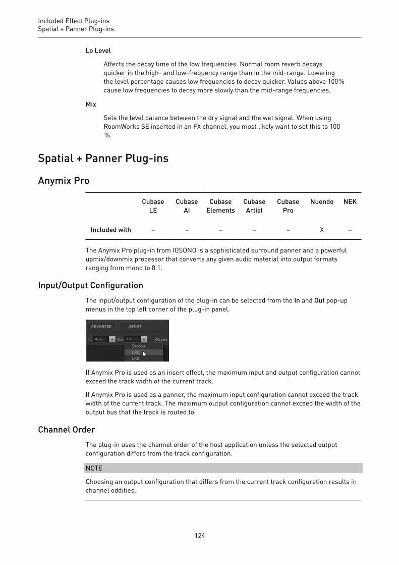
Included Effect Plug-insSpatial + Panner Plug-ins
Lo Level
Affects the decay time of the low frequencies. Normal room reverb decaysquicker in the high- and low-frequency range than in the mid-range. Loweringthe level percentage causes low frequencies to decay quicker. Values above 100 %cause low frequencies to decay more slowly than the mid-range frequencies.
Mix
Sets the level balance between the dry signal and the wet signal. When usingRoomWorks SE inserted in an FX channel, you most likely want to set this to 100 %.
Spatial + Panner Plug-ins
Anymix Pro
CubaseLE
CubaseAI
CubaseElements
CubaseArtist
CubasePro
Nuendo NEK
Included with – – – – – X –
The Anymix Pro plug-in from IOSONO is a sophisticated surround panner and a powerfulupmix/downmix processor that converts any given audio material into output formatsranging from mono to 8.1.
Input/Output ConfigurationThe input/output configuration of the plug-in can be selected from the In and Out pop-upmenus in the top left corner of the plug-in panel.
If Anymix Pro is used as an insert effect, the maximum input and output configuration cannotexceed the track width of the current track.
If Anymix Pro is used as a panner, the maximum input configuration cannot exceed the trackwidth of the current track. The maximum output configuration cannot exceed the width of theoutput bus that the track is routed to.
Channel OrderThe plug-in uses the channel order of the host application unless the selected outputconfiguration differs from the track configuration.
NOTE
Choosing an output configuration that differs from the current track configuration results inchannel oddities.
124

Included Effect Plug-insSpatial + Panner Plug-ins
If the output configuration of the track is not a subset of the plug-in output configuration, forexample, track = 6.1 cine and plug-in output = 7.0 music, the channels are routed as follows:
1 2 3 4 5 6 7 8 9
L R C LFE LS RS RSS/ RC LSS/ LC CS
NOTE
Channels that are missing in the output configuration are automatically skipped.
1 2 3 4 5 6 7 8 9
Track configuration:6.1 Cine
L R C LFE LS RS CS
Plug-in outputconfiguration: 7.0 Music
L R C LS RS LSS RSS
Result OK Mismatch
Latency CompensationAnymix Pro causes a processing delay. The amount of latency depends on the buffer size ofthe audio card and the processing mode of the plug-in, that is, panning or upmix. Steinberghost applications can compensate this delay automatically.
The Plug-in PanelThe panel of Anymix Pro is divided into several sections, with the stage view taking the mostspace to display the position and movement of the input channels, output configuration, anddistance-dependent filter values. On the right side, there are the controls for position andmovement, and the lower section of the plug-in panel contains the upmix controls.
NOTE
The plug-in panel has two different display modes: panning and upmix.
125

Included Effect Plug-insSpatial + Panner Plug-ins
Panning Mode
In the stage view, input channels are represented by red icons, output channels by grayspeakers in the background.
Moving the input channels outside the loudspeaker setup results in panning between thetwo nearest output speakers. The input channels that are placed at smaller distances aredistributed to several output speakers.
• To change the position of the input group, click and drag anywhere in the stage view,or right-click in the stage view. Right-clicking causes the channels to jump to the newposition.
NOTE
The distance between the input channels automatically shrinks if they are moved to theborder of the stage. This lets you create the illusion of depth when moving stereo or multi-channel material.
Position SectionIn addition to using the stage view, the input channels can also be moved using the controlsat the top right of the plug-in panel.
Rotation
Rotates the input group around its center point.
126
Included Effect Plug-insSpatial + Panner Plug-ins
Link Angle & Rotation
Changes the rotation of the input group from self-centered to stage-centered.
Depth
Scales the input group vertically.
Width
Scales the input group horizontally.
Link Depth & Width
Keeps the aspect ratio between Depth and Width scaling.
NOTE
To fine-adjust the parameters, press Shift while using the controls.
Individual Channel AdjustmentYou can change the positions of the input channels individually by double-clicking thecorresponding input icon in the stage view. A separate panel with channel-specificparameters opens.
Radius/Angle
Control the position of the selected input channel, relative to the center of theinput group.
X/Y
Move the selected input channel horizontally and vertically.
Volume
Applies gain to the selected input channel.
LFE Volume
Controls the amount of LFE for the selected input channel.
Spread
Distributes the audio from the selected input channel to more than two outputchannels.
• At 0 % the audio source is rendered where the channel icon is placed.• At 100 % the audio is evenly distributed to all speakers of the output
configuration.
127

Included Effect Plug-insSpatial + Panner Plug-ins
Manual Delay
Adds a delay to the selected input channel.
Link
Activate these buttons to link the corresponding parameters in the current plug-in instance. Adjusting the value of a linked parameter changes the other linkedparameters, too.
IMPORTANT
The individual input channel parameters cannot be automated from the host application, butthe adjustments you make for each input channel are saved for each plug-in instance andpanner in the session.
Restricting MovementYou can use the double-arrow buttons at the top right of the stage view to restrict thedirection of movement of the object in the stage view to orthogonal or diagonal, for easyautomation.
NOTE
In most cases, objects move on very simple routes around the audience. By restricting thedirection of movement, you can quickly create accurate movements.
Distance-Dependent FiltersTo create immersive mixes even faster, Anymix Pro is equipped with a distance-dependentfilter unit that lets you adjust the volume and air damping of moving objects automatically.
Loudness
Lowers the volume for objects that are further away.
EQ
Dampens the high frequencies of objects that are further away.
For both of the filters, you can select one the following options from the corresponding pop-up menu:
• OffDeactivates the distance-dependent filter.
• LinearThe filtering starts right from the center point and is applied linearly. Select this curvetype if even tiny movements should have an impact on the distance-dependent filter.
128

Included Effect Plug-insSpatial + Panner Plug-ins
• SinusoidalThe filtering starts approximately at loudspeaker distance and increases exponentiallywith distance. Select this curve type if movements in the center circle should have noaudible impact on the distance-dependent filter.
• EllipticalThe filtering starts approximately at two thirds of the stage with an exponentialattenuation curve. Select this curve type if only movements along the border of thestage should have an impact on the distance-dependent filter.
NOTE
The current values can be shown in the speaker icon labels, using the Display pop-up menuabove the stage view.
The distance-dependent filters can be further adjusted using the advanced options.
RELATED LINKSAdvanced Options on page 134
UpmixThe upmix feature of Anymix Pro is very useful if rearranging tracks with fewer inputchannels into a specific surround format is not enough.
The upmix algorithm analyzes the incoming audio signal and separates it into parts of directsound and ambient sound. While the direct sound parts are sent to the direct sound streamand can be placed at the virtual front speaker configuration, the ambient sound parts can bemodified and arranged around the virtual stage. Note that this does not add any additionalinformation to the audio stream. All sound parts that you hear from the ambient sound werealready part of the original audio material.
IMPORTANT
If your audio does not contain spatial information, there cannot be an ambient sound stream.For example, you cannot extract ambient sound from a dry recording of a narrator sitting in arecording booth.
IMPORTANT
Lossy compression, such as in MP3 files, or other deficiencies of the incoming audio cannotbe remedied using the upmix mode. For example, compression artifacts can easily bemisinterpreted and redistributed to the ambient sound stream.
Switching to Upmix Mode• To switch to upmix mode, activate the Enable option in the Upmix section to the right of
the stage view.
NOTE
The upmix algorithm is very sophisticated and can cause a high CPU load. Therefore, youcannot automate the Enable option.
129

Included Effect Plug-insSpatial + Panner Plug-ins
Stage ViewIn upmix mode, the parameters are represented by segments of a circle in the stage view.
NOTE
The position parameters for the input group and any created automation are preserved whenthe upmix is enabled. In upmix mode, the sound image created by the upmix algorithm canbe moved around the stage and is also fully automatable. The parameters that you haveadjusted for a single channel have no influence on the upmix, but they are kept and areautomatically reloaded when the upmix is disabled.
Upmix PresetsAnymix Pro comes with a set of preconfigured upmix presets. If a preset is loaded, the upmixand advanced parameters are set accordingly and can be further adjusted.
An upmix preset contains settings for the following upmix parameters:
• Divergence• Stage Width• Direct Dry/Wet• Ambience Gain• Ambience Front/Rear• Ambience Low Pass
130

Included Effect Plug-insSpatial + Panner Plug-ins
• Ambience Delay.
Furthermore, the following parameters on the Advanced panel are affected by the preset:
• LFE Gain• LFE Low Pass Enable• LFE Low Pass Order• LFE Low Pass Cutoff Frequency• Output Gain.
NOTE
Upmix presets from the Cinema category are designed for the use with X-curve tunedspeaker systems. The other presets are designed for listening environments with a flatspeaker tuning.
Input – BalanceAdjusts the balance of the input signal if the input signal is stereo or higher.
Upmix – Orig./UpmixAdjusts the plug-in output between original and processed signal.
Direct Sound Stream ParametersDivergence
Controls the strength of the center signal.
• At 0 % the mono components of the direct sound stream are distributed tothe center channel.
• At 100 % the mono components of the direct sound stream are distributedto the front left and right channels.
Stage Width
Controls the position of the front channels to adjust the stereo base.
Dry/Wet
Controls the amount of ambience that remains in the direct sound stream afterthe ambience extraction.
Ambient Sound Stream ParametersGain
Applies gain to the ambient sound stream to either emphasize (high gain) ordampen (low gain) the amount of ambience in the mix.
Front/Rear
Adjusts the front/rear balance of the ambient sound stream.
Low Pass
Controls the ambient sound stream with a low-pass filter to prevent hissing.
131
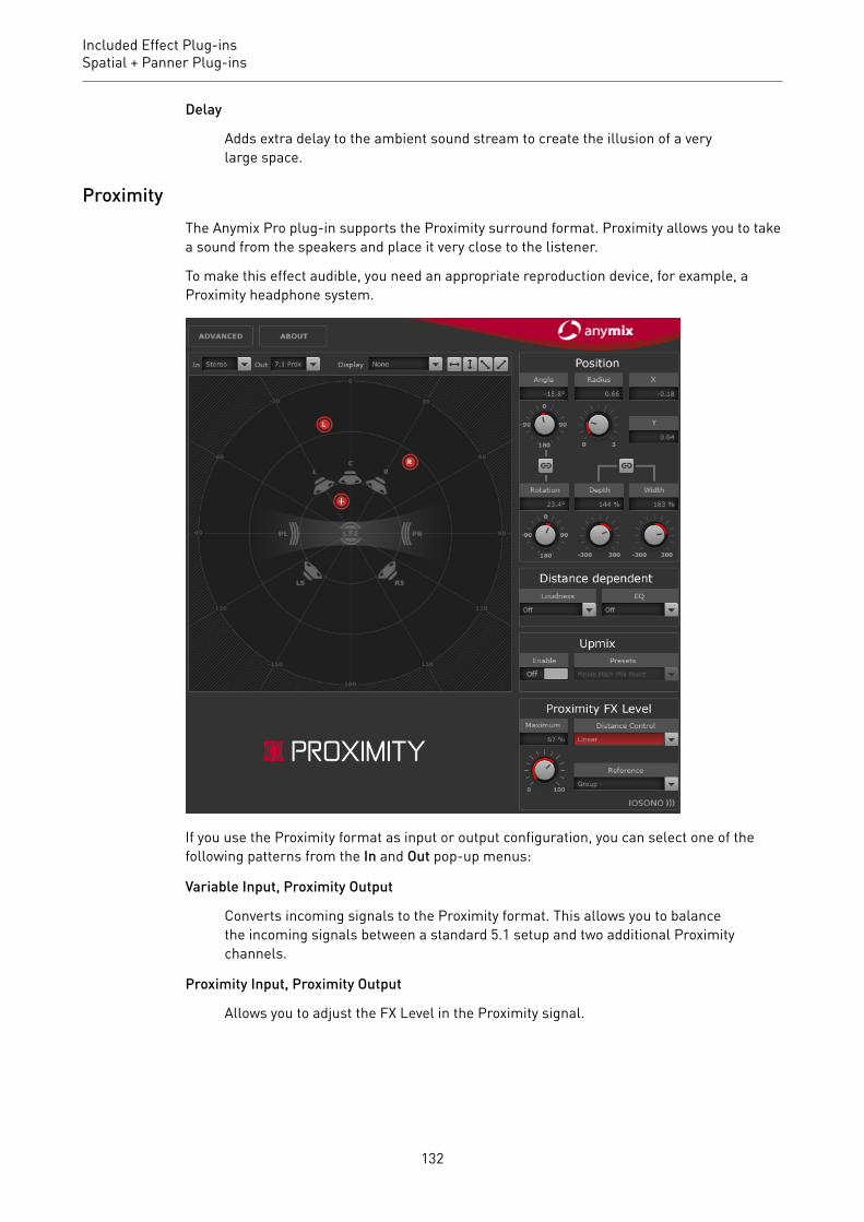
Included Effect Plug-insSpatial + Panner Plug-ins
Delay
Adds extra delay to the ambient sound stream to create the illusion of a verylarge space.
ProximityThe Anymix Pro plug-in supports the Proximity surround format. Proximity allows you to takea sound from the speakers and place it very close to the listener.
To make this effect audible, you need an appropriate reproduction device, for example, aProximity headphone system.
If you use the Proximity format as input or output configuration, you can select one of thefollowing patterns from the In and Out pop-up menus:
Variable Input, Proximity Output
Converts incoming signals to the Proximity format. This allows you to balancethe incoming signals between a standard 5.1 setup and two additional Proximitychannels.
Proximity Input, Proximity Output
Allows you to adjust the FX Level in the Proximity signal.
132
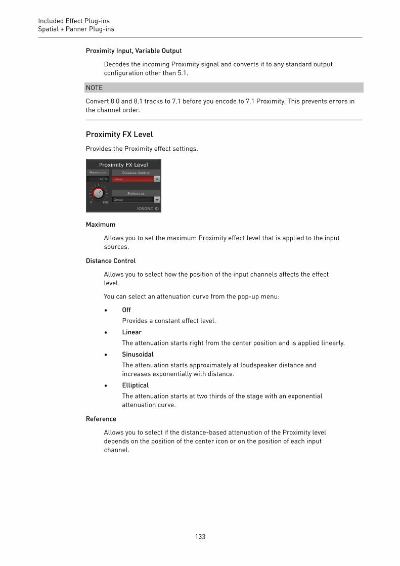
Included Effect Plug-insSpatial + Panner Plug-ins
Proximity Input, Variable Output
Decodes the incoming Proximity signal and converts it to any standard outputconfiguration other than 5.1.
NOTE
Convert 8.0 and 8.1 tracks to 7.1 before you encode to 7.1 Proximity. This prevents errors inthe channel order.
Proximity FX LevelProvides the Proximity effect settings.
Maximum
Allows you to set the maximum Proximity effect level that is applied to the inputsources.
Distance Control
Allows you to select how the position of the input channels affects the effectlevel.
You can select an attenuation curve from the pop-up menu:
• OffProvides a constant effect level.
• LinearThe attenuation starts right from the center position and is applied linearly.
• SinusoidalThe attenuation starts approximately at loudspeaker distance andincreases exponentially with distance.
• EllipticalThe attenuation starts at two thirds of the stage with an exponentialattenuation curve.
Reference
Allows you to select if the distance-based attenuation of the Proximity leveldepends on the position of the center icon or on the position of each inputchannel.
133
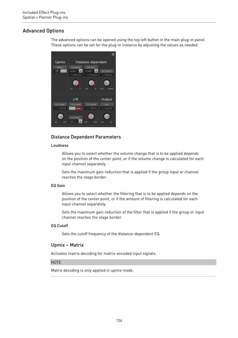
Included Effect Plug-insSpatial + Panner Plug-ins
Advanced OptionsThe advanced options can be opened using the top left button in the main plug-in panel.These options can be set for the plug-in instance by adjusting the values as needed.
Distance Dependent ParametersLoudness
Allows you to select whether the volume change that is to be applied dependson the position of the center point, or if the volume change is calculated for eachinput channel separately.
Sets the maximum gain reduction that is applied if the group input or channelreaches the stage border.
EQ Gain
Allows you to select whether the filtering that is to be applied depends on theposition of the center point, or if the amount of filtering is calculated for eachinput channel separately.
Sets the maximum gain reduction of the filter that is applied if the group or inputchannel reaches the stage border.
EQ Cutoff
Sets the cutoff frequency of the distance-dependent EQ.
Upmix – MatrixActivates matrix decoding for matrix-encoded input signals.
NOTE
Matrix decoding is only applied in upmix mode.
134

Included Effect Plug-insSpatial + Panner Plug-ins
LFE ParametersLFE Gain
Sets a separate gain level for the LFE channel that is applied to the plug-inoutput.
LP Enable
Enables a low-pass filter that is applied to the LFE output channel after summingthe signals from the input channels.
LP Cutoff
Sets the cutoff frequency for the generated LFE channel.
LP Order
Allows you to select the order, or slope, of the low-pass filter.
• 2nd order = 12 dB/octave• 3rd order = 18 dB/octave• 4th order = 24 dB/octave
NOTE
The amount of LFE can be adjusted for each input channel individually.
NOTE
If the selected input configuration includes an LFE channel, but the selected outputconfiguration does not, the LFE input channel is distributed to front left and front right at alevel of -3 dB automatically. The low-pass filter is applied to the incoming LFE signal beforeit is distributed to the front speakers.
MonoToStereoThis effect turns a mono signal into a pseudo-stereo signal. The plug-in can be used on amono file or a stereo file with equal channels.
CubaseLE
CubaseAI
CubaseElements
CubaseArtist
CubasePro
Nuendo NEK
Included with – X X X X X –
NOTE
This plug-in works only on stereo tracks.
135

Included Effect Plug-insSpatial + Panner Plug-ins
Width
Controls the width or depth of the stereo enhancement. Turn clockwise toincrease the enhancement.
Delay
Increases the amount of differences between the left and right channels tofurther increase the stereo effect.
Color
Generates additional differences between the channels to increase the stereoenhancement.
Mono
Switches the output to mono, to check for possible unwanted coloring of thesound which sometimes can occur when creating an artificial stereo image.
StereoEnhancerThis plug-in expands the stereo width of (stereo) audio material. It cannot be used with monofiles.
CubaseLE
CubaseAI
CubaseElements
CubaseArtist
CubasePro
Nuendo NEK
Included with – – X X X X –
NOTE
This plug-in works only on stereo tracks.
Width
Controls the width or depth of the stereo enhancement. Turn clockwise toincrease the enhancement.
136

Included Effect Plug-insSurround Plug-ins
Delay
Increases the amount of differences between the left and right channels tofurther increase the stereo effect.
Color
Generates additional differences between the channels to increase the stereoenhancement.
Mono
Switches the output to mono, to check for possible unwanted coloring of thesound which sometimes can occur when enhancing the stereo image.
VST MultiPanner
CubaseLE
CubaseAI
CubaseElements
CubaseArtist
CubasePro
Nuendo NEK
Included with – – – – X X –
For a description of VST MultiPanner, see the Operation Manual.
NOTE
In Cubase, VST MultiPanner is only available as a channel panner, but not as an insert effect.
Surround Plug-ins
Bass ManagerIf your main speakers are small, this plug-in allows you to achieve full-range sound by usingthe LFE speaker of the studio as a subwoofer. If your LFE is small but the main speakersprovide full-range sound, the plug-in allows you to strengthen the LFE sound by routinghigher frequencies from the LFE to the main speakers.
CubaseLE
CubaseAI
CubaseElements
CubaseArtist
CubasePro
Nuendo NEK
Included with – – – – – X –
137

Included Effect Plug-insSurround Plug-ins
If your monitoring system is connected directly to your audio interface and lacks a bassmanagement system, you can use Bass Manager in the Control Room inserts to adjust thesignal levels and signal routing of the LFE and main speakers. Thus, small speakers canachieve full-range sound.
Input/Output Level MetersLevel In
Shows the level of the input signal.
Level Out
Shows the level of the output signal.
MainsSubwoofer
If this is activated, the low part of the main speakers is routed to the subwoofer.
Freq
Sets the crossover frequency. Frequencies below this value are routed to thesubwoofer.
Gain
Sets the amount of attenuation/boost of the signal that is routed to thesubwoofer.
LFECenter
If this is activated, the LFE signal is routed to the center channel.
L/R
If this is activated, the LFE signal is routed to the left and right channels.
138

Included Effect Plug-insSurround Plug-ins
Freq
Sets the crossover frequency. Frequencies above this value are routed to the leftand right channels or to the center channel.
Gain
Sets the amount of attenuation/boost of the signal that is routed to the left andright channels or to the center channel.
+10 dB
Boosts the level of the LFE signal by 10 dB.
SubwooferSolo
Solos the subwoofer signal.
Mute
Mutes the subwoofer signal.
Low Cut
Additional low-cut filter for the subwoofer.
High Cut
Additional high-cut filter for the subwoofer.
+10 dB
Boosts the level of the subwoofer signal by 10 dB.
NOTE
You can also use the graphical displays to set the parameters or enter the parameter valuesmanually in the value fields.
MatrixDecoderThe MatrixDecoder reverses the encoder process performed by the MatrixEncoder. It is usedfor monitoring how an encoded mix sounds when played back on a Pro Logic compatiblesystem.
CubaseLE
CubaseAI
CubaseElements
CubaseArtist
CubasePro
Nuendo NEK
Included with – – – – – X –
139
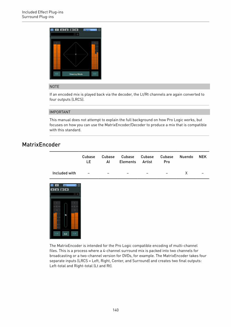
Included Effect Plug-insSurround Plug-ins
NOTE
If an encoded mix is played back via the decoder, the Lt/Rt channels are again converted tofour outputs (LRCS).
IMPORTANT
This manual does not attempt to explain the full background on how Pro Logic works, butfocuses on how you can use the MatrixEncoder/Decoder to produce a mix that is compatiblewith this standard.
MatrixEncoder
CubaseLE
CubaseAI
CubaseElements
CubaseArtist
CubasePro
Nuendo NEK
Included with – – – – – X –
The MatrixEncoder is intended for the Pro Logic compatible encoding of multi-channelfiles. This is a process where a 4-channel surround mix is packed into two channels forbroadcasting or a two-channel version for DVDs, for example. The MatrixEncoder takes fourseparate inputs (LRCS = Left, Right, Center, and Surround) and creates two final outputs:Left-total and Right-total (Lt and Rt).
140

Included Effect Plug-insSurround Plug-ins
Setting Up
PROCEDURE1. In the VST Connections window, create an output bus with the LRCS channel
configuration and route it to the physical outputs of your audio hardware.This is if you want to make a four-channel surround mix. If you want to make a five-channel mix, use MatrixEncoder with the 5.0 Surround Format.
2. Place the MatrixEncoder in the first post-fader insert slot (#7) for the output bus,followed by the MatrixDecoder (#8).
RELATED LINKSUsing the MatrixEncoder with the 5.0 Surround Format on page 142
Using the MatrixEncoder/Decoder
PROCEDURE1. Set up the mix roughly the way you want it.
Use the VST MultiPanner to place channels in the surround mix, or assign channels tothe individual LRCS outputs.
2. Activate the MatrixEncoder.What you now hear is the encoded stereo mix, the way it sounds when it is played backon a normal stereo reproducer. On the MatrixEncoder control panel, you can adjust theGain of the Lt/Rt output by using the fader.
3. Activate the MatrixDecoder, open the control panel and click the Steering Mode button.Now you can hear how the mix is reproduced in surround on a Pro Logic compatiblesystem.
The Steering display shows an x within the surround field. The position of this xindicates the dominant direction of the mix, sometimes referred to as the dominancevector. Part of the processing that is applied results in the dominant channel beingenhanced and the non-dominant channels being reduced in gain.
4. By activating and deactivating the Bypass button in the MatrixDecoder, you cancompare the decoded mix with the encoded stereo mix, and make adjustments in theMixConsole as necessary.The main goal is to produce a mix that sounds good in both the encoded and thedecoded version. To compare the encoded or decoded mix with the unprocessed mix,switch off both the MatrixEncoder and the Decoder.
141
Included Effect Plug-insSurround Plug-ins
IMPORTANTThe encoding/decoding process produces significant signal loss compared to theunprocessed mix. This is normal, and does not indicate that something is not workingproperly. However, with careful tweaking of the mix, you can decrease the signaldegradation to a much more acceptable level. You have to adjust levels and othersettings before the signal runs through the MatrixEncoder, because neither theencoder or decoder can control the mix in any way.
5. If you are satisfied with the result, bypass the MatrixDecoder, or remove it from itseffect slot.
6. Connect a master recording device to the stereo mix output and perform a mixdown asusual.
RESULT
The resulting encoded stereo mix is compatible with common home systems that use the ProLogic standard.
Using the MatrixEncoder with the 5.0 Surround FormatThere are situations where you may want to mix for several surround formats. For example,you might need to mix the same material for 5.1 and LRCS.
5.1 is similar to LRCS. Omitting the LFE channel is easy, but more of a problem is that LRCSonly has one surround channel whereas 5.1 has two.
For this reason, the MatrixEncoder sums up the surround channels to a mono signal.
PROCEDURE1. Create your mix for 5.1.2. In the VST Connections window, create an output bus with a 5.0 channel configuration
and route it to the physical outputs of your audio hardware.3. Run the mix through the MatrixEncoder.
RESULT
First, the two surround channels are merged to make the mix compatible with LRCS.Then, the four resulting signals are encoded as usual. This way, far fewer adjustments arenecessary when working with 5.1 and LRCS at the same time.
Using the MatrixDecoder with the 5.0 Surround FormatNormally, two surround speakers are used even when playing back LRCS. The two speakersthen simply use the same material. The MatrixDecoder simulates this by delivering thesurround channel to two outputs. This allows you to move between formats and listeningsituations with less repatching of speaker channels.
142
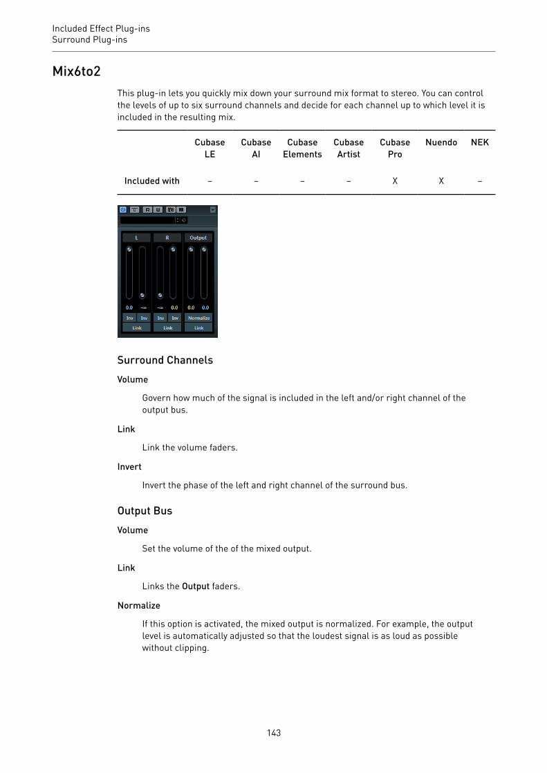
Included Effect Plug-insSurround Plug-ins
Mix6to2This plug-in lets you quickly mix down your surround mix format to stereo. You can controlthe levels of up to six surround channels and decide for each channel up to which level it isincluded in the resulting mix.
CubaseLE
CubaseAI
CubaseElements
CubaseArtist
CubasePro
Nuendo NEK
Included with – – – – X X –
Surround ChannelsVolume
Govern how much of the signal is included in the left and/or right channel of theoutput bus.
Link
Link the volume faders.
Invert
Invert the phase of the left and right channel of the surround bus.
Output BusVolume
Set the volume of the of the mixed output.
Link
Links the Output faders.
Normalize
If this option is activated, the mixed output is normalized. For example, the outputlevel is automatically adjusted so that the loudest signal is as loud as possiblewithout clipping.
143
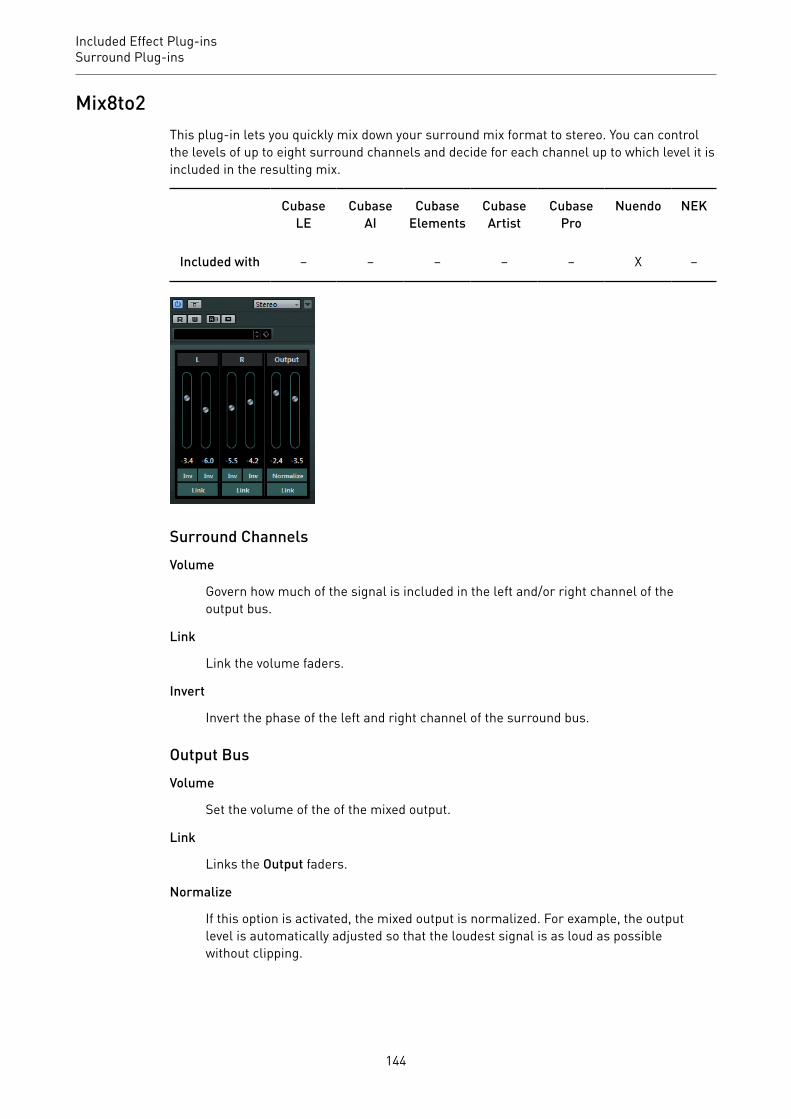
Included Effect Plug-insSurround Plug-ins
Mix8to2This plug-in lets you quickly mix down your surround mix format to stereo. You can controlthe levels of up to eight surround channels and decide for each channel up to which level it isincluded in the resulting mix.
CubaseLE
CubaseAI
CubaseElements
CubaseArtist
CubasePro
Nuendo NEK
Included with – – – – – X –
Surround ChannelsVolume
Govern how much of the signal is included in the left and/or right channel of theoutput bus.
Link
Link the volume faders.
Invert
Invert the phase of the left and right channel of the surround bus.
Output BusVolume
Set the volume of the of the mixed output.
Link
Links the Output faders.
Normalize
If this option is activated, the mixed output is normalized. For example, the outputlevel is automatically adjusted so that the loudest signal is as loud as possiblewithout clipping.
144

Included Effect Plug-insSurround Plug-ins
MixConvert V6The MixConvert V6 plug-in can be used to quickly convert a multi-channel mix to a formatwith a different channel configuration, for example, to mix down a 7.1 cinema surroundformat to a 5.1 home theater format.
CubaseLE
CubaseAI
CubaseElements
CubaseArtist
CubasePro
Nuendo NEK
Included with – – – – X X –
MixConvert V6 can be used as an insert effect like other plug-ins but it also has specialfunctions. The MixConvert V6 plug-in is also used to convert an audio-related channel intoa different format if the corresponding input/output configuration is not handled by VSTMultiPanner. The sequencer application places MixConvert V6 automatically where needed.
Input/Output Channel ConfigurationThe input configuration is determined by the channel width of the track, group, or output buson which MixConvert V6 is inserted.
If MixConvert V6 replaces the panner, the output configuration is determined by thedestination of the channel or cue send.
If MixConvert V6 is used as an insert effect, the output configuration can be modified usingthe Select Output Channel Configuration pop-up menu. You can select any configurationfrom the VST 3 specification that contains speakers that are also present in the inputconfiguration.
NOTE
You can change the output configuration by loading a preset.
ParametersThe plug-in panel is divided into three sections: By default, only the center section is visible,the input and output channel displays can be shown to the left and right of the centersection.
145

Included Effect Plug-insSurround Plug-ins
• To show/hide the input or output channel configuration, click the corresponding arrowbutton.
The center section contains the main plug-in parameters as well as buttons for soloingseveral speakers in one go.
Solo Channel buttons
Solo all front channels, the LFE channel, or all surround channels in the input oroutput display. All other channels are muted.
Listen to Solo Channels on Center Channel
Routes all soloed channels to the center channel. If no center channel is present,the signal from the soloed channels is distributed equally to the left and rightspeakers.
Listen to Surround Channels on Front Channels
Solos all surround channels, including the side channels, and routes ordownmixes them to the front speakers.
Center Level
Controls the level of the front center channel.
LFE fader
Controls the level of the LFE channel.
Surround Level
Controls the level of the surround channels. The level of the surround channelscannot be adjusted individually.
Global Gain
Controls the level of all output channels.
Activate/Deactivate Low-Pass Filter
Activates the low-pass filter that is applied to the LFE channel.
RELATED LINKSVST MultiPanner on page 137
Soloing Channels in the Channel Displays• To solo a channel, click the corresponding speaker icon.
You can solo several channels at the same time. All other channels are muted.• To deactivate the solo state of a channel, click the corresponding speaker icon again.• To solo a channel exclusively, Ctrl/Cmd-click the corresponding speaker icon.• To solo the LFE channel, click the corresponding cross-hair icon in the center of the
channel display.This corresponds to the Solo Input/Output LFE Channel button in the center section.
146

Included Effect Plug-insSurround Plug-ins
• To mute a channel, Shift-click the corresponding speaker icon.
Depending on whether you solo a channel in the input or output configuration, the followingapplies:
• For output configurations, you can only hear the soloed speaker’s channel in thedownmix.
• For input configurations, you can hear the influence of the soloed speaker’s channel onthe downmix.
MixerDelayMixerDelay allows you to adjust and manipulate each individual channel in a surround track,group or bus.
CubaseLE
CubaseAI
CubaseElements
CubaseArtist
CubasePro
Nuendo NEK
Included with – – – – X X –
Above the individual channel controls, you find global buttons for turning off Mute, Solo andInvert Phase switches for all channels.
Mute
Allows you to mute individual channels.
Solo
Allows you to solo individual channels.
Inv
Lets you invert the phase or polarity for individual channels.
Delay
Allows you to delay individual speaker channels. The delay times are shownin milliseconds and centimeters, making this feature very useful for distancecompensation when playing back surround mixes on different speaker setups,etc.
Level
Allows you to fine-tune the volume balance between the surround channels.
Volume
Shows the level of the input signal.
147
Included Effect Plug-insTools Plug-ins
Routing
Lets you select/switch the outputs for the channels quickly. You can assign thesame output to several channels by holding down Alt while selecting. Note thatthere are also several channel routing presets available.
NOTE
It is common for the center channel in a 5.1 speaker configuration to be closer to the mixposition in order to accommodate large video monitors or projection screens. MixerDelay canbe used to compensate for the center channel being too close. Simply adjust the delay for thecenter channel by the difference in distance (in cm) between it and the other speakers to themix position. You must delay the closer speaker so that the sound from it arrives at the sametime as the sound from the more distant speakers. Note that MixerDelay has a wide range(up to 1000 ms) and fine adjustments are best made by numerically entering the delay time incentimeters for speaker alignment.
IMPORTANT
The MixerDelay is not a mixer – the number of outputs is the same as the number of inputs.If you need to mix down a surround signal to stereo, use the Mix6to2, Mix8to2 or MixConvertV6 plug-ins.
Tools Plug-ins
MultiScopeMultiScope can be used for viewing the waveform, phase linearity, or frequency content of asignal.
CubaseLE
CubaseAI
CubaseElements
CubaseArtist
CubasePro
Nuendo NEK
Included with – – – – X X –
There are three different modes:
• Oscilloscope (Ampl.)• Phase Correlator (Scope)• Frequency Spectrum Analyzer (Freq.)
148

Included Effect Plug-insTools Plug-ins
Oscilloscope Mode (Ampl.)
If Ampl. is activated, the display shows signal waveform.
Channel menu
If the source signal is stereo, you can select the Left or Right channel for viewing,or Stereo for both channels to be shown in the window.
If MultiScope is used with a multi-channel track or output bus, you can select anyspeaker channel for viewing, or All Channels to view them all at once.
Freeze
Freezes the display.
Mode A/Mode B
This option is not available for this mode.
Amplitude
Allows you to increase/decrease the vertical size of the waveform.
Frequency
Allows you to select the frequency area for viewing.
149
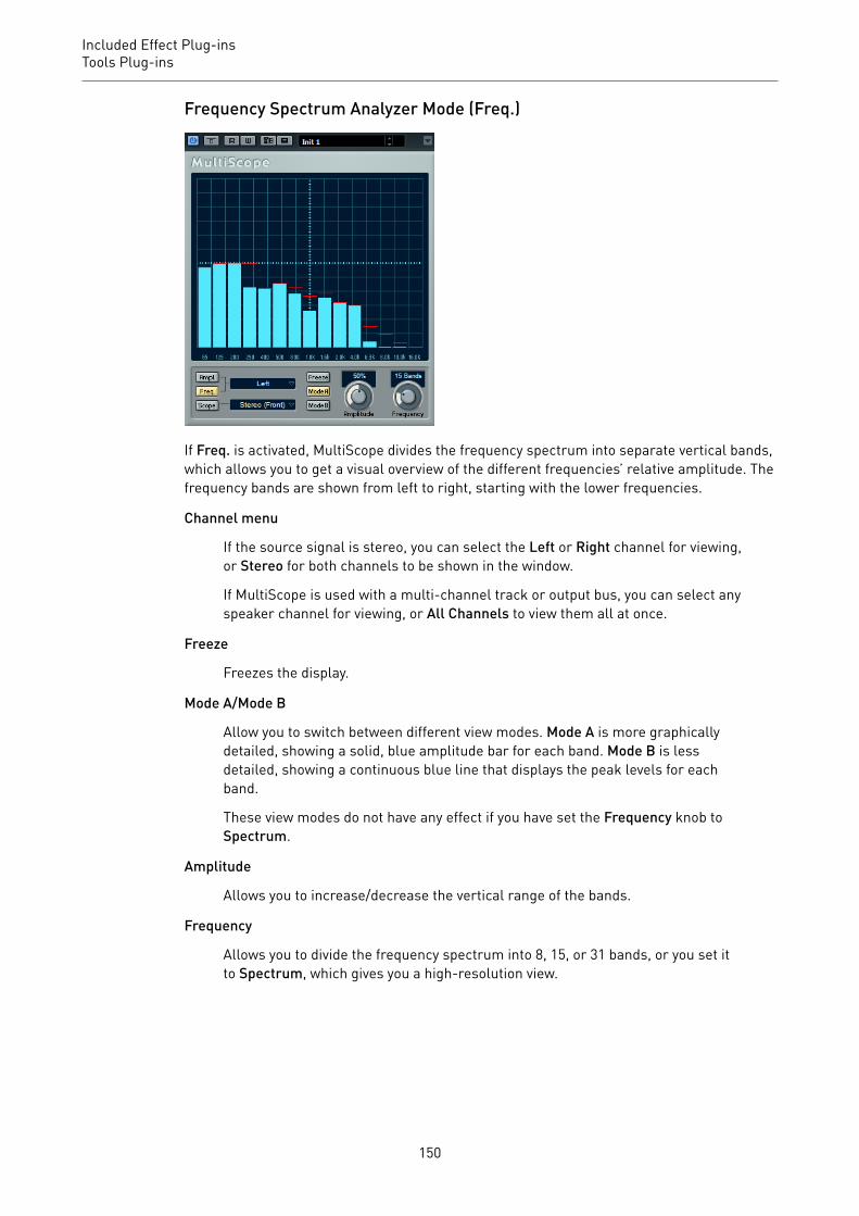
Included Effect Plug-insTools Plug-ins
Frequency Spectrum Analyzer Mode (Freq.)
If Freq. is activated, MultiScope divides the frequency spectrum into separate vertical bands,which allows you to get a visual overview of the different frequencies’ relative amplitude. Thefrequency bands are shown from left to right, starting with the lower frequencies.
Channel menu
If the source signal is stereo, you can select the Left or Right channel for viewing,or Stereo for both channels to be shown in the window.
If MultiScope is used with a multi-channel track or output bus, you can select anyspeaker channel for viewing, or All Channels to view them all at once.
Freeze
Freezes the display.
Mode A/Mode B
Allow you to switch between different view modes. Mode A is more graphicallydetailed, showing a solid, blue amplitude bar for each band. Mode B is lessdetailed, showing a continuous blue line that displays the peak levels for eachband.
These view modes do not have any effect if you have set the Frequency knob toSpectrum.
Amplitude
Allows you to increase/decrease the vertical range of the bands.
Frequency
Allows you to divide the frequency spectrum into 8, 15, or 31 bands, or you set itto Spectrum, which gives you a high-resolution view.
150
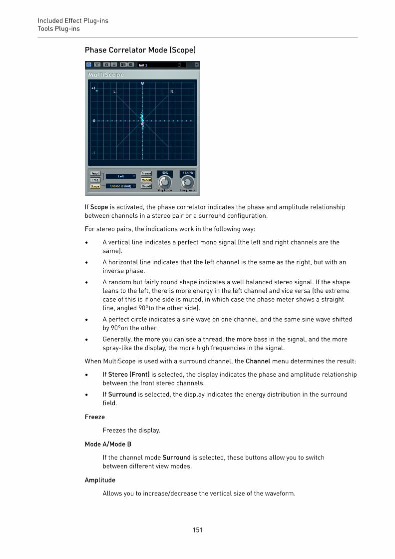
Included Effect Plug-insTools Plug-ins
Phase Correlator Mode (Scope)
If Scope is activated, the phase correlator indicates the phase and amplitude relationshipbetween channels in a stereo pair or a surround configuration.
For stereo pairs, the indications work in the following way:
• A vertical line indicates a perfect mono signal (the left and right channels are thesame).
• A horizontal line indicates that the left channel is the same as the right, but with aninverse phase.
• A random but fairly round shape indicates a well balanced stereo signal. If the shapeleans to the left, there is more energy in the left channel and vice versa (the extremecase of this is if one side is muted, in which case the phase meter shows a straightline, angled 90°to the other side).
• A perfect circle indicates a sine wave on one channel, and the same sine wave shiftedby 90°on the other.
• Generally, the more you can see a thread, the more bass in the signal, and the morespray-like the display, the more high frequencies in the signal.
When MultiScope is used with a surround channel, the Channel menu determines the result:
• If Stereo (Front) is selected, the display indicates the phase and amplitude relationshipbetween the front stereo channels.
• If Surround is selected, the display indicates the energy distribution in the surroundfield.
Freeze
Freezes the display.
Mode A/Mode B
If the channel mode Surround is selected, these buttons allow you to switchbetween different view modes.
Amplitude
Allows you to increase/decrease the vertical size of the waveform.
151

Included Effect Plug-insTools Plug-ins
Frequency
Allows you to select the frequency area for viewing.
SMPTEGeneratorThis plug-in is not a real audio effect. It sends out SMPTE timecode to an audio output,allowing you to synchronize other equipment to your host application (provided that theequipment can synchronize directly to SMPTE timecode). This can be very useful if you do nothave access to a MIDI-to-timecode converter.
CubaseLE
CubaseAI
CubaseElements
CubaseArtist
CubasePro
Nuendo NEK
Included with – – – – X X –
Main timecode display
This display shows the current timecode.
If Link to Transport is deactivated, the generator is in free run mode. You can usethe timecode display to set the SMPTE start time.
If Link to Transport is activated, you cannot change any of the values. This displayshows the current timecode in sync with the Transport panel. Where applicable,the offset defined in the offset timecode display is taken into account.
Frame rate display and pop-up menu
The frame rate shown to the right of the timecode display corresponds to theframe rate set in the Project Setup dialog. To generate timecode in a differentframe rate (for example, to stripe a tape), select another format on the pop-upmenu (only available if Link to Transport is deactivated).
NOTE
For another device to synchronize correctly to your host, the same frame ratehas to be set in the Project Setup dialog, the SMPTE Generator, and the receivingdevice.
Offset timecode display
This display is only available if Link to Transport is activated. It allows you toset an offset with regard to the timecode used by your host application. Theoffset affects the generated SMPTE signal, the current cursor position remainsunaffected.
152
Included Effect Plug-insTools Plug-ins
For example, use this when playing back video using an external device, wherethe video starts at a different timecode position than in your host. A scenariocould be as follows: You have placed the same video several times on thetimeline, in order to record different audio versions for that video one after theother. However, since video playback is done via an external machine (replayingthe same video), you need an offset to match the different timecode positions inyour host with the (unchanging) start position on the external machine.
Generate Code
If this button is activated, the plug-in generates SMPTE timecode in free runmode, meaning that it outputs continuous timecode independent from theTransport panel. Use this mode if you want to stripe tape with SMPTE.
Link to Transport
If this button is activated, the timecode is synchronized to the Transport panel.
Timecode in Still Mode
If this button is activated, the plug-in also generates SMPTE timecode instop mode. However, note that this is not continuous timecode, but timecodegenerated at the current cursor position. For example, this can be useful whenworking with video editing software that interprets the absence of timecode asa stop command. By using this option, the video software can enter still modeinstead so that a still frame is shown instead of a blank screen.
NOTE
To change one of the timecode values (main and offset timecode displays), double-click onany of the timecode fields and enter a new value.
Synchronizing a Device to Your Host
PROCEDURE1. Use the SMPTE Generator as an insert effect on an audio track, and route that track to
a separate output.Make sure that no other insert or send effect is used on this track. Deactivate any EQsettings for this track.
2. Connect the corresponding output on the audio hardware to the timecode input on thedevice that you want to synchronize to your host application.Make all necessary settings for the external device so that it synchronizes to incomingtimecode.
3. Optional: Adjust the level of the timecode, either in your host application or in thereceiving device.Activate the Generate Code button (make the device send the SMPTE timecode in freerun mode) to test the level.
4. Make sure that the frame rate in the receiving device matches the frame rate set in theSMPTE Generator.
5. Activate the Link to Transport button.The SMPTE Generator now outputs timecode that corresponds to the time display ofyour host application.
153
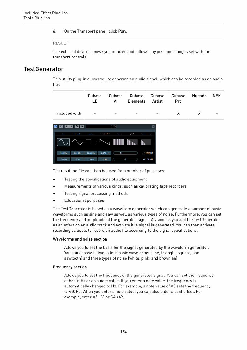
Included Effect Plug-insTools Plug-ins
6. On the Transport panel, click Play.
RESULT
The external device is now synchronized and follows any position changes set with thetransport controls.
TestGeneratorThis utility plug-in allows you to generate an audio signal, which can be recorded as an audiofile.
CubaseLE
CubaseAI
CubaseElements
CubaseArtist
CubasePro
Nuendo NEK
Included with – – – – X X –
The resulting file can then be used for a number of purposes:
• Testing the specifications of audio equipment• Measurements of various kinds, such as calibrating tape recorders• Testing signal processing methods• Educational purposes
The TestGenerator is based on a waveform generator which can generate a number of basicwaveforms such as sine and saw as well as various types of noise. Furthermore, you can setthe frequency and amplitude of the generated signal. As soon as you add the TestGeneratoras an effect on an audio track and activate it, a signal is generated. You can then activaterecording as usual to record an audio file according to the signal specifications.
Waveforms and noise section
Allows you to set the basis for the signal generated by the waveform generator.You can choose between four basic waveforms (sine, triangle, square, andsawtooth) and three types of noise (white, pink, and brownian).
Frequency section
Allows you to set the frequency of the generated signal. You can set the frequencyeither in Hz or as a note value. If you enter a note value, the frequency isautomatically changed to Hz. For example, a note value of A3 sets the frequencyto 440 Hz. When you enter a note value, you can also enter a cent offset. Forexample, enter A5 -23 or C4 +49.
154

Included Effect Plug-insTools Plug-ins
NOTE
Ensure that you enter a space between the note and the cent offset. Only in thiscase, the cent offsets are taken into account.
Gain section
Allows you to set the amplitude of the signal. The higher the value, the strongerthe signal. You can select one of the preset values, or use the slider to set a valuebetween -81 and 0 dB.
TunerThis is a guitar tuner.
IMPORTANT
Make sure that you deactivate any other effect that alters pitch, like chorus or vibrato.
CubaseLE
CubaseAI
CubaseElements
CubaseArtist
CubasePro
Nuendo NEK
Included with X X X X X X –
Simply connect a guitar or other instrument to an audio input and select Tuner as an inserteffect.
IMPORTANT
To use Tuner, you must activate Monitor for the track with Tuner.
You can display Tuner in an analog view or in a digital view.
• To switch between analog view and digital view, click the Switch between analog view
and digital view button in the upper left corner of the plug-in.
Analog View
When you play a note, the pitch is shown in the middle of the display. The frequency in Hz isshown in the bottom left corner and the octave range in the bottom right corner.
The two arrows indicate any deviation in pitch. If the pitch is flat, they are positioned in theleft half of the display, if the pitch is sharp they are in the right half. The deviation is alsoshown in the upper area of the display.
155

Included Effect Plug-insTools Plug-ins
• If a string is out of tune (for example, if the pitch for the E string is shown as Eb), tunethe string so that the correct pitch is shown and the two arrows are in the middle.Repeat this procedure for each string.
• To mute the output signal so that you can tune the strings in silence, activate the Mutebutton at the bottom middle of the plug-in panel.
Digital View (Cubase Pro and Nuendo only)
Note
Displays the currently played pitch.
Cent
Displays the value, deviating from Note. A negative value indicates that the pitchis flat. A positive value indicates that the pitch is sharp.
Strobe/Classic
You can switch the display between two modes: Strobe and Classic.
In Strobe mode, a blue indicator constantly runs from right to left, that is frompositive to negative. The more flat a note is, the faster the indicator moves. Assoon as you play a sharp tone, the running direction of the indicator runs fromleft to right, that is from negative to positive. When you play the correct pitch, theindicator stops and the display turns gray.
When you play a note in Classic mode, the pitch is shown in the middle of thedisplay. When you play the correct pitch, the middle of the indicator turns gray.
Base
Displays the frequency of the base note A. Its default value is 440 Hz. You canadjust Base by ± 15 Hz.
Octave
Displays the octave.
156
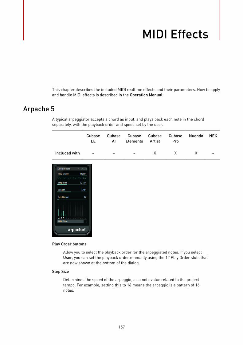
MIDI Effects
This chapter describes the included MIDI realtime effects and their parameters. How to applyand handle MIDI effects is described in the Operation Manual.
Arpache 5A typical arpeggiator accepts a chord as input, and plays back each note in the chordseparately, with the playback order and speed set by the user.
CubaseLE
CubaseAI
CubaseElements
CubaseArtist
CubasePro
Nuendo NEK
Included with – – – X X X –
Play Order buttons
Allow you to select the playback order for the arpeggiated notes. If you selectUser, you can set the playback order manually using the 12 Play Order slots thatare now shown at the bottom of the dialog.
Step Size
Determines the speed of the arpeggio, as a note value related to the projecttempo. For example, setting this to 16 means the arpeggio is a pattern of 16notes.
157
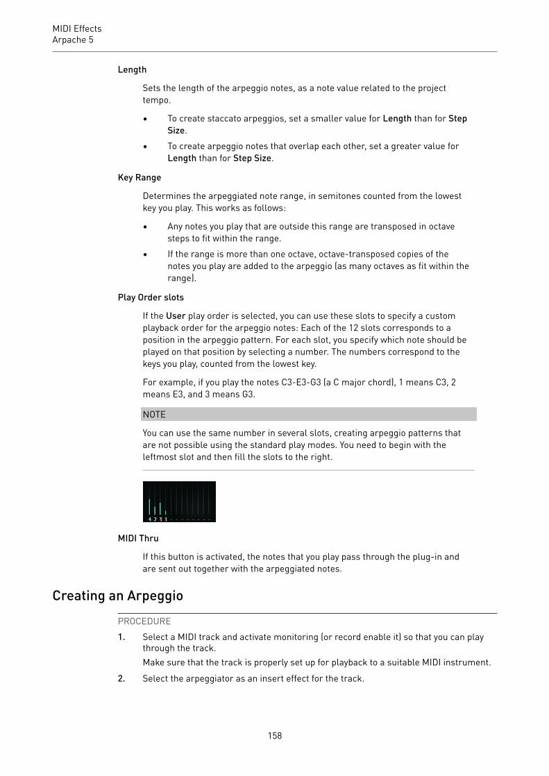
MIDI EffectsArpache 5
Length
Sets the length of the arpeggio notes, as a note value related to the projecttempo.
• To create staccato arpeggios, set a smaller value for Length than for StepSize.
• To create arpeggio notes that overlap each other, set a greater value forLength than for Step Size.
Key Range
Determines the arpeggiated note range, in semitones counted from the lowestkey you play. This works as follows:
• Any notes you play that are outside this range are transposed in octavesteps to fit within the range.
• If the range is more than one octave, octave-transposed copies of thenotes you play are added to the arpeggio (as many octaves as fit within therange).
Play Order slots
If the User play order is selected, you can use these slots to specify a customplayback order for the arpeggio notes: Each of the 12 slots corresponds to aposition in the arpeggio pattern. For each slot, you specify which note should beplayed on that position by selecting a number. The numbers correspond to thekeys you play, counted from the lowest key.
For example, if you play the notes C3-E3-G3 (a C major chord), 1 means C3, 2means E3, and 3 means G3.
NOTE
You can use the same number in several slots, creating arpeggio patterns thatare not possible using the standard play modes. You need to begin with theleftmost slot and then fill the slots to the right.
MIDI Thru
If this button is activated, the notes that you play pass through the plug-in andare sent out together with the arpeggiated notes.
Creating an ArpeggioPROCEDURE1. Select a MIDI track and activate monitoring (or record enable it) so that you can play
through the track.Make sure that the track is properly set up for playback to a suitable MIDI instrument.
2. Select the arpeggiator as an insert effect for the track.
158
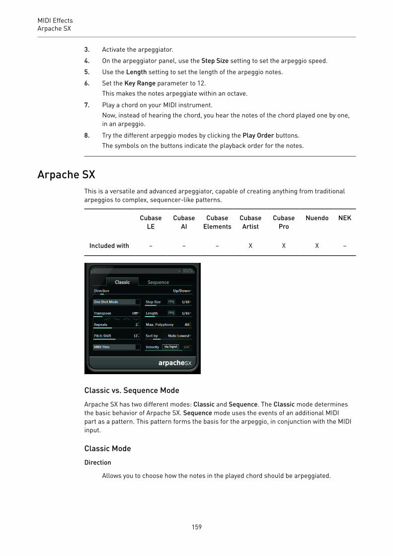
MIDI EffectsArpache SX
3. Activate the arpeggiator.4. On the arpeggiator panel, use the Step Size setting to set the arpeggio speed.5. Use the Length setting to set the length of the arpeggio notes.6. Set the Key Range parameter to 12.
This makes the notes arpeggiate within an octave.
7. Play a chord on your MIDI instrument.Now, instead of hearing the chord, you hear the notes of the chord played one by one,in an arpeggio.
8. Try the different arpeggio modes by clicking the Play Order buttons.The symbols on the buttons indicate the playback order for the notes.
Arpache SXThis is a versatile and advanced arpeggiator, capable of creating anything from traditionalarpeggios to complex, sequencer-like patterns.
CubaseLE
CubaseAI
CubaseElements
CubaseArtist
CubasePro
Nuendo NEK
Included with – – – X X X –
Classic vs. Sequence ModeArpache SX has two different modes: Classic and Sequence. The Classic mode determinesthe basic behavior of Arpache SX. Sequence mode uses the events of an additional MIDIpart as a pattern. This pattern forms the basis for the arpeggio, in conjunction with the MIDIinput.
Classic ModeDirection
Allows you to choose how the notes in the played chord should be arpeggiated.
159
MIDI EffectsArpache SX
One Shot Mode
Activate this option if you want the phrase to be played only once. If this option isdeactivated, the phrase is looped.
Transpose
With a setting other than Off, the arpeggio is expanded upwards, downwards, orboth (depending on the mode). This is done by adding transposed repeats of thebasic arpeggio pattern.
Repeats
Sets the number of transposed repeats.
Pitch Shift
Determines the transposition of each repeat.
MIDI Thru
If this is activated, the played notes pass through the plug-in and are sent outtogether with the arpeggiated notes.
Step Size
Determines the resolution of the arpeggio, that is, its speed (in fixed note valuesor PPQ, if the PPQ button is activated). In Sequence mode you can also activatethe from sequence option.
Length
Determines the length of the arpeggio notes (in fixed note values or PPQ, if thePPQ button is activated).
Max. Polyphony
Determines how many notes should be accepted in the input chord. The Allsetting means there are no limitations.
Sort by
If you play a chord, the arpeggiator sorts the notes in the chord in the orderspecified here. For example, if you play a C-E-G chord, with Note Lowestselected, C is the first note, E is the second and G the third. This affects the resultof the Arp Style setting.
Velocity
Determines the velocity of the notes in the arpeggio. Using the slider you can seta fixed velocity, or you can activate the via Input button to use the velocity valuesof the notes in the chord you play. In Sequence mode you can also activate thefrom sequence option.
Sequence ModeIn Sequence mode, you can import a MIDI part into Arpache SX by dragging it from theProject window onto the Drop MIDI Sequence field on the right of the Arpache SX panel.
The notes in the dropped MIDI part are sorted internally, either according to their pitch if theMIDI Seq. sort by pitch checkbox is activated or according to their play order in the part. This
160

MIDI EffectsArpache SX
results in a list of numbers. For example, if the notes in the MIDI part are C E G A E C andthey are sorted according to pitch, the list of numbers reads 1 2 3 4 2 1. Here, there are 4different notes/numbers and 6 trigger positions.
The MIDI input (the chord you play) generates a list of numbers, with each note in the chordcorresponding to a number depending on the Sort by setting.
Furthermore, the two lists of numbers are matched – Arpache SX tries to play back thepattern from the dropped MIDI part but using the notes from the MIDI input. The resultdepends on the Play Mode setting.
Trigger
The whole pattern from the dropped MIDI file is played back, but transposedaccording to one of the notes in the MIDI input. Which note is used fortransposing depends on the Sort by setting.
Trigger Cnt.
As above, but even if all keys are released, the phrase continues playing from thelast position (where it stopped), if a new key is pressed on the keyboard. This istypically used when playing live through the Arpache SX.
Sort Normal
Matches the notes in the MIDI input with the notes in the dropped MIDI part. Ifthere are fewer notes in the MIDI input, some steps in the resulting arpeggioremain empty.
Sort First
As above, but if there are fewer notes in the MIDI input, the missing notes arereplaced by the first note.
Sort Any
As above, but if there are fewer notes in the MIDI input, the missing notes arereplaced by random notes.
Arp. Style
As above, but if there are fewer notes in the MIDI input, the missing notes arereplaced by the last valid note in the arpeggio.
Repeat
In this mode, the chords played are not separated into notes. Instead, they areused as is, and only the rhythm of the dropped MIDI part is used for playback.
NOTE
You can choose to keep the original note timing, note length, and note velocities from thedropped MIDI part, by selecting from sequence for the Step Size, Length, and Velocityoptions.
161

MIDI EffectsAuto LFO
Auto LFOThis effect works like an LFO in a synthesizer, allowing you to send out continuouslychanging MIDI controller messages. One typical use for this is automatic MIDI panning, butyou can select any MIDI continuous controller event type.
CubaseLE
CubaseAI
CubaseElements
CubaseArtist
CubasePro
Nuendo NEK
Included with – – – X X X –
Waveform
Determines the shape of the controller curves that are sent out. You can click awaveform symbol or choose a value from the pop-up menu.
Wavelength
Sets the speed of Auto LFO, or rather the length of a single controller curve cycle.You can set this to rhythmically exact note values or PPQ values if the PPQ buttonis activated. The lower the note value, the slower the speed.
Controller Type
Determines which continuous controller type is sent out. Typical choiceswould include pan, volume, and brightness, but your MIDI instrument mayhave controllers mapped to various settings, allowing you to modulate thesynth parameter of your choice. Check the MIDI implementation chart for yourinstrument for details.
Density
Determines the density of the controller curves that are sent out. The valuecan be set to small, medium, or large, or to rhythmically exact note values. Thehigher the note value, the smoother the controller curve.
Value Range
These sliders determine the range of controller values that are sent out, in otherwords, the bottom and top of the controller curves.
162
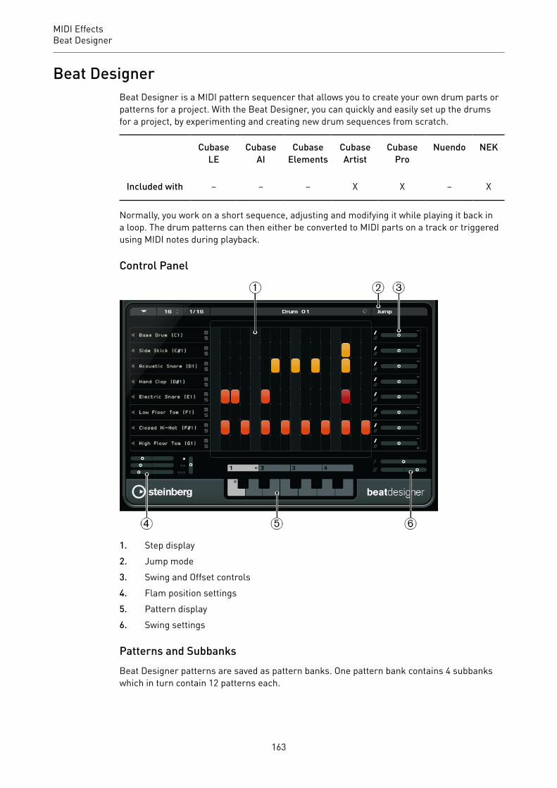
MIDI EffectsBeat Designer
Beat DesignerBeat Designer is a MIDI pattern sequencer that allows you to create your own drum parts orpatterns for a project. With the Beat Designer, you can quickly and easily set up the drumsfor a project, by experimenting and creating new drum sequences from scratch.
CubaseLE
CubaseAI
CubaseElements
CubaseArtist
CubasePro
Nuendo NEK
Included with – – – X X – X
Normally, you work on a short sequence, adjusting and modifying it while playing it back ina loop. The drum patterns can then either be converted to MIDI parts on a track or triggeredusing MIDI notes during playback.
Control Panel
1. Step display2. Jump mode3. Swing and Offset controls4. Flam position settings5. Pattern display6. Swing settings
Patterns and SubbanksBeat Designer patterns are saved as pattern banks. One pattern bank contains 4 subbankswhich in turn contain 12 patterns each.
163
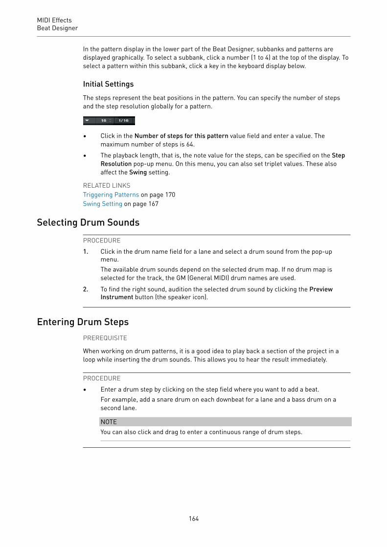
MIDI EffectsBeat Designer
In the pattern display in the lower part of the Beat Designer, subbanks and patterns aredisplayed graphically. To select a subbank, click a number (1 to 4) at the top of the display. Toselect a pattern within this subbank, click a key in the keyboard display below.
Initial SettingsThe steps represent the beat positions in the pattern. You can specify the number of stepsand the step resolution globally for a pattern.
• Click in the Number of steps for this pattern value field and enter a value. Themaximum number of steps is 64.
• The playback length, that is, the note value for the steps, can be specified on the StepResolution pop-up menu. On this menu, you can also set triplet values. These alsoaffect the Swing setting.
RELATED LINKSTriggering Patterns on page 170Swing Setting on page 167
Selecting Drum SoundsPROCEDURE1. Click in the drum name field for a lane and select a drum sound from the pop-up
menu.The available drum sounds depend on the selected drum map. If no drum map isselected for the track, the GM (General MIDI) drum names are used.
2. To find the right sound, audition the selected drum sound by clicking the PreviewInstrument button (the speaker icon).
Entering Drum StepsPREREQUISITE
When working on drum patterns, it is a good idea to play back a section of the project in aloop while inserting the drum sounds. This allows you to hear the result immediately.
PROCEDURE• Enter a drum step by clicking on the step field where you want to add a beat.
For example, add a snare drum on each downbeat for a lane and a bass drum on asecond lane.
NOTEYou can also click and drag to enter a continuous range of drum steps.
164

MIDI EffectsBeat Designer
Removing StepsPROCEDURE• To remove a drum step, simply click on the corresponding field again.
NOTETo remove a range of drum steps, click and drag over them.
Velocity SettingsWhen entering a drum step, the velocity setting of this step is determined by where you click:Click in the upper part of a step for the highest velocity setting, in the middle section fora medium velocity and in the lower part for the lowest velocity setting. In the display, thedifferent velocity settings are indicated by different colors.
• To fine-tune the velocity setting for an existing drum step, click on it and drag up ordown. The current velocity is indicated numerically while you drag.
• To fine-tune the velocity for a range of drum steps, click on the first step, drag up ordown to enter velocity edit mode, and then drag sideways and up or down to modify thevelocity for all the steps.If you change the velocity for several steps at the same time, the relative velocitydifferences are kept for as long as possible (until the minimum or maximum setting isreached). The velocity for the steps is increased or decreased by the same amount.
NOTEIf you hold down Shift while dragging up or down, you can change the velocity for allsteps on a lane.
• To create a crescendo or decrescendo for an existing range of drum steps, hold downAlt, click on the first step, drag up or down, and then drag to the left or right.
Editing Operations• To move all drum steps on a lane, hold down Shift, click on the lane, and drag to the
left or right.• To invert a lane, that is, add drum sounds for all steps that were empty while removing
all existing drum steps, hold down Alt and drag the mouse over the lane. This lets youcreate unusual rhythmic patterns.
• To copy the content of a lane onto another lane, hold down Alt, click in the section tothe left of the lane that you want to copy, and drag.
Lane Handling• To add a lane, click the Add Instrument Lane button at the bottom right of the last
lane.• To remove a lane, click the Remove Instrument Lane button in the controls section at
the far right of the lane.• To change the order of the drum lanes, click in an empty area in the section to the left
of a lane, and drag it to another position.
165

MIDI EffectsBeat Designer
• To mute or solo a lane, click the corresponding buttons to the left of the step display.
IMPORTANT
Lane operations always affect all patterns in the Beat Designer instance.
Pattern Functions Menu
Shift Left
Moves all steps of the current pattern on all lanes to the left.
Shift Right
Moves all steps of the current pattern on all lanes to the right.
Reverse
Reverses the pattern, so that it plays backwards.
Copy Pattern
Copies the pattern to the clipboard. Copied patterns can be pasted into anotherpattern subbank and even directly into the project.
Paste Pattern
Allows you to paste a complete pattern, for example, into another patternsubbank, or into another instance of the Beat Designer. This is useful if you wantto create variations based on existing patterns.
Clear Pattern
Resets the current pattern.
Insert Pattern at Cursor
Creates a MIDI part for the current pattern and inserts it in the Project window, atthe position of the project cursor.
Insert Subbank at Cursor
Creates a MIDI part for each used pattern in the subbank and inserts the partsone after the other, starting at the project cursor.
166
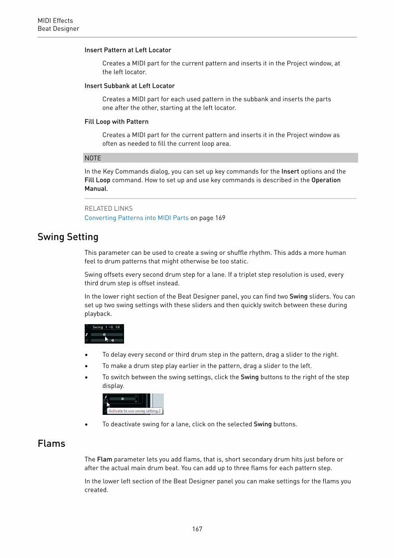
MIDI EffectsBeat Designer
Insert Pattern at Left Locator
Creates a MIDI part for the current pattern and inserts it in the Project window, atthe left locator.
Insert Subbank at Left Locator
Creates a MIDI part for each used pattern in the subbank and inserts the partsone after the other, starting at the left locator.
Fill Loop with Pattern
Creates a MIDI part for the current pattern and inserts it in the Project window asoften as needed to fill the current loop area.
NOTE
In the Key Commands dialog, you can set up key commands for the Insert options and theFill Loop command. How to set up and use key commands is described in the OperationManual.
RELATED LINKSConverting Patterns into MIDI Parts on page 169
Swing SettingThis parameter can be used to create a swing or shuffle rhythm. This adds a more humanfeel to drum patterns that might otherwise be too static.
Swing offsets every second drum step for a lane. If a triplet step resolution is used, everythird drum step is offset instead.
In the lower right section of the Beat Designer panel, you can find two Swing sliders. You canset up two swing settings with these sliders and then quickly switch between these duringplayback.
• To delay every second or third drum step in the pattern, drag a slider to the right.• To make a drum step play earlier in the pattern, drag a slider to the left.• To switch between the swing settings, click the Swing buttons to the right of the step
display.
• To deactivate swing for a lane, click on the selected Swing buttons.
FlamsThe Flam parameter lets you add flams, that is, short secondary drum hits just before orafter the actual main drum beat. You can add up to three flams for each pattern step.
In the lower left section of the Beat Designer panel you can make settings for the flams youcreated.
167

MIDI EffectsBeat Designer
The first position slider specifies the flam position for all steps containing one single flam,the second slider the flam positions for all steps containing two flams, and the third sliderthe flam position for all steps containing three flams.
Adding Flams
PROCEDURE1. Click in the lower left corner of the step you want to add a flam to.
Little squares appear in the step when you point the mouse at it. If you click a step, thefirst square is filled to indicate that you added a flam.
2. Click again to add the second and third flam.3. In the lower left section of the Beat Designer panel, make settings for the flams that
you created.
• To add the flams before or after the drum step, drag a position slider to the leftor right.If you add flams before the first drum step in a pattern, this is indicated in thedisplay by a small arrow in the top left corner of this step. Starting playback atthe normal pattern start would result in these flams not being played.
• To set the velocity for the flams, use the vertical sliders to the right of the flamsliders.
4. Start playback to hear the flams you created.
Offsetting LanesTo the right of the step display, you can find the Offset sliders for the lanes. These allow youto offset all drum steps on this lane.
PROCEDURE1. Drag a slider to the left to make the drum steps start a little earlier and to the right to
let them start later.For example, playing the bass drum or snare a little earlier allows you to add moreurgency to the drums, while delaying these drum sounds results in a more relaxeddrum pattern.
2. Experiment with the settings to find out which fit best in your project.
NOTEThis function can also be used to correct faulty drum samples: If a drum sound has anattack that is slightly late, simply adjust the Offset slider for the lane.
168

MIDI EffectsBeat Designer
Using the Drum Patterns in Your Project
Converting Patterns into MIDI PartsYou can convert the drum patterns created in the Beat Designer into a MIDI part by draggingthem into the Project window.
PROCEDURE1. Set up one or more patterns of the same subbank.2. In the lower part of the window, click on a pattern or subbank and drag it onto a MIDI
or instrument track in the Project window.
• If you drag the pattern or subbank to an empty area in the Project window, a newMIDI track is created. This is an exact copy of the original track for which youopened the Beat Designer.
• If you drag a single pattern into the Project window, one MIDI part is createdcontaining the drum sounds of the pattern.
• If you drag a subbank into the Project window, several MIDI parts (one for eachused pattern in the subbank) are created and inserted one after the other in theproject.
IMPORTANTOnly the used patterns in a subbank are inserted. If you did not enter drum steps in apattern, this is not converted into a MIDI part.
You can also use the Pattern Functions menu to insert patterns or subbanks into theproject.
IMPORTANTWhen you have created MIDI parts for your drum patterns this way, make sure todeactivate the Beat Designer, to avoid doubling of the drums. The Beat Designercontinues to play as long as it is activated.
• If you import patterns that sound before the first step (due to flams or laneoffsets), the MIDI part is lengthened accordingly.
The inserted MIDI parts can now be edited as usual in the project. For example, youcan fine-tune your settings in the Drum Editor.
NOTEOnce a pattern is converted into a MIDI part, it cannot be opened in the Beat Designeragain.
RELATED LINKSPattern Functions Menu on page 166
169

MIDI EffectsChorder
Triggering PatternsIf you want to modify your drum patterns in Beat Designer while working on the project, youcan trigger the patterns from within the project.
You can trigger the patterns in Beat Designer using note-on events. These can either beevents on a MIDI track or be played live via a MIDI keyboard. Which pattern is triggereddepends on the pitch of the MIDI notes. The trigger range is four octaves starting with C1(that is, C1 to B4).
PROCEDURE1. Open Beat Designer for a track.2. Click the Jump field to activate Jump mode.
In this mode, a MIDI note-on event triggers a new pattern.
• To trigger the patterns using a MIDI part containing trigger events, you canspecify whether the pattern is switched instantly (at the moment the eventis received) or at the next bar: Activate the Now button to switch patternsimmediately. If Now is deactivated, patterns switch at the beginning of the nextbar in the project.
• If you want to trigger the patterns live via a MIDI keyboard, the new patterns arealways played when the next bar in the project is reached. Switching immediatelywould always produce an undesirable interruption in playback.
3. Play back the project and press a key on your MIDI keyboard to trigger the next pattern.The pattern starts at the next bar line.
4. Create a MIDI part and enter notes at the positions in the project where you want toswitch patterns.Depending on the Jump mode setting, the new pattern is played instantly, or starts atthe following bar.
• You can also drag a pattern or subbank into the Project with Jump modeactivated to automatically create MIDI parts containing the trigger events.
NOTEWhen triggering a pattern that contains sound before the first step (due to flams orlane offsets), these are taken into account as well.
ChorderChorder is a MIDI chord processor, allowing you to assign complete chords to single keys in amultitude of variations. These can then be played back live or using recorded notes on a MIDItrack.
CubaseLE
CubaseAI
CubaseElements
CubaseArtist
CubasePro
Nuendo NEK
Included with – – – X X X –
170
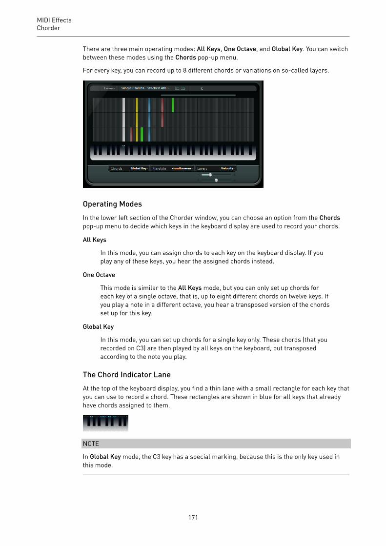
MIDI EffectsChorder
There are three main operating modes: All Keys, One Octave, and Global Key. You can switchbetween these modes using the Chords pop-up menu.
For every key, you can record up to 8 different chords or variations on so-called layers.
Operating ModesIn the lower left section of the Chorder window, you can choose an option from the Chordspop-up menu to decide which keys in the keyboard display are used to record your chords.
All Keys
In this mode, you can assign chords to each key on the keyboard display. If youplay any of these keys, you hear the assigned chords instead.
One Octave
This mode is similar to the All Keys mode, but you can only set up chords foreach key of a single octave, that is, up to eight different chords on twelve keys. Ifyou play a note in a different octave, you hear a transposed version of the chordsset up for this key.
Global Key
In this mode, you can set up chords for a single key only. These chords (that yourecorded on C3) are then played by all keys on the keyboard, but transposedaccording to the note you play.
The Chord Indicator LaneAt the top of the keyboard display, you find a thin lane with a small rectangle for each key thatyou can use to record a chord. These rectangles are shown in blue for all keys that alreadyhave chords assigned to them.
NOTE
In Global Key mode, the C3 key has a special marking, because this is the only key used inthis mode.
171

MIDI EffectsChorder
RELATED LINKSUsing Layers on page 173
Entering ChordsPROCEDURE1. Activate the Learn button at the top of the Chorder window to activate Learn mode.
The chord indicator lane is now tinted red, indicating that it is active.
The keyboard display in Learn mode
The second layer in Learn mode
2. Select the key to which you want to assign a chord by clicking on it on the keyboarddisplay or by pressing the key on a connected MIDI keyboard.The red bar now moves to the first layer, indicating that you are ready to record thefirst chord.
NOTEIn Global Key mode, you do not have to choose a trigger key. The first layer is activatedautomatically.
3. Play a chord on the MIDI keyboard and/or use the mouse to enter or change the chordin the layer display.
• Any notes you enter are immediately shown in the Chorder display. The notes areshown in different colors, depending on the pitch.
• If you are entering chords via a MIDI keyboard, Chorder learns the chord as soonas you release all keys of your MIDI keyboard.As long as a key is pressed, you can continue looking for the right chord.
• If more than one layer is shown, Chorder jumps automatically to the next layerwhere you can record another chord.If all layers for a key are filled, the red bar jumps back to the keyboard display sothat you can choose a different trigger key (in Global Key mode, the Learn modeis deactivated).
• If you are entering chords with the mouse, Chorder does not jump to the nextlayer automatically.You can select/deselect as many notes as you want and then click on anotherlayer or deactivate the Learn mode to continue.
4. Repeat the above with any other keys you want to use.
172

MIDI EffectsChorder
Using LayersThe Layers pop-up menu at the bottom right of the window allows you to set up chordvariations in the layer display above the keyboard. This works with all three modes andprovides up to 8 variations for each assignable key, that is, a maximum of 8 different chordsin Global Key mode, 12 x 8 chords in One Octave mode and 128 x 8 chords in All Keys mode.
The different layers can be triggered by velocity or interval.
PROCEDURE1. On the Layers pop-up menu, select Velocity or Interval. Set this to Single Mode if you
want to set up only one chord per key.2. Use the slider below the Layers pop-up menu to specify how many variations you want
to use.3. Enter the chords.
RESULT
Now you can play the keyboard and trigger the variations according to the selected layermode.
RELATED LINKSEmpty Layers on page 173
Layer ModesYou can play the keyboard and trigger the variations according to the selected layer mode.
Velocity
The full velocity range (1 to 127) is divided into zones, according to the number oflayers you specified. For example, if you are using 2 variations, 2 velocity zonesare used: 1 to 63 and 64 to 127. Playing a note with velocity 64 or higher triggersthe second layer, while playing a softer note triggers the first layer.
With the Velocity spread slider at the bottom right of the window, you can changethe velocity ranges of the layers.
Interval
In this mode Chorder plays one chord at a time. If the Interval mode isselected, you trigger a layer by pressing 2 keys on your keyboard. The lower keydetermines the base note for the chord. The layer number is determined by thedifference between the 2 keys. To select layer 1, press a key one semitone higherthan the base note, for layer 2, press a key two semitones higher, and so on.
Single Mode
Select this if you want to use only 1 layer.
Empty LayersIf you enter fewer chords than layers are available for a key, these layers are filledautomatically when you deactivate the Learn mode.
The following applies:
173
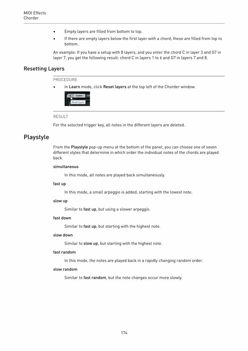
MIDI EffectsChorder
• Empty layers are filled from bottom to top.• If there are empty layers below the first layer with a chord, these are filled from top to
bottom.
An example: If you have a setup with 8 layers, and you enter the chord C in layer 3 and G7 inlayer 7, you get the following result: chord C in layers 1 to 6 and G7 in layers 7 and 8.
Resetting Layers
PROCEDURE• In Learn mode, click Reset layers at the top left of the Chorder window.
RESULT
For the selected trigger key, all notes in the different layers are deleted.
PlaystyleFrom the Playstyle pop-up menu at the bottom of the panel, you can choose one of sevendifferent styles that determine in which order the individual notes of the chords are playedback.
simultaneous
In this mode, all notes are played back simultaneously.
fast up
In this mode, a small arpeggio is added, starting with the lowest note.
slow up
Similar to fast up, but using a slower arpeggio.
fast down
Similar to fast up, but starting with the highest note.
slow down
Similar to slow up, but starting with the highest note.
fast random
In this mode, the notes are played back in a rapidly changing random order.
slow random
Similar to fast random, but the note changes occur more slowly.
174

MIDI EffectsCompressor
CompressorThis MIDI compressor is used for evening out or expanding differences in velocity.
CubaseLE
CubaseAI
CubaseElements
CubaseArtist
CubasePro
Nuendo NEK
Included with – – – X X X –
Threshold
Only notes with velocities above this value are affected by the compression/expansion.
Ratio
Sets the amount of compression applied to the velocity values above the setthreshold. Ratios greater than 1:1 result in compression. Ratios lower than 1:1result in expansion.
Gain
Adds or subtracts a fixed value from the velocities. Since the maximum range forvelocity values is 0 to 127, you can use the Gain setting to compensate, keepingthe resulting velocities within the range. Typically, negative Gain settings areused for expansion and positive settings for compression.
Context GateContext Gate allows for selective triggering/filtering of MIDI data.
CubaseLE
CubaseAI
CubaseElements
CubaseArtist
CubasePro
Nuendo NEK
Included with – – – X X X –
175

MIDI EffectsContext Gate
This effect features two modes: in Poly Mode the Context Gate recognizes certain chords thatare played and in Mono Mode only certain MIDI notes are let through.
Poly ModePolyphony Gate
Allows you to filter MIDI according to the number of pressed keys within a givenkey range. This can be used independently or in conjunction with the Chord Gatefunction.
• The Key Range Limit sliders set the key range. Only notes within this rangeare let through.
• The Minimum Polyphony value field allows you to specify the minimumnumber of notes required to open the gate.
Chord Gate
If Chord Gate is activated, only notes in recognized chords are let through. TwoRecognition modes are available: Simple and Normal.
• In Simple mode, all standard chords (major/minor/b5/dim/sus/maj7 etc.)are recognized.
• Normal mode takes more tensions into account.
Mono ModeChannel Gate
If this is activated, only single note events of the specified MIDI channel are letthrough. This can be used with MIDI controllers that can send MIDI on severalchannels simultaneously, for example, guitar controllers which send data foreach string over a separate channel.
• You can set Mono Channel to a specific channel (1 to 16), or to Any, that is,no channel gating.
Velocity Gate
This can be used independently or in conjunction with the Channel Gate function.Notes are played back until another note within the set range is played.
• The Key Range Limit sliders set the key range. Only notes within this rangeare let through.
176

MIDI EffectsDensity
• Notes below the Minimum Velocity threshold value are gated.
Auto Gate Time
If there is no input activity, you can specify the time, after which note-offmessages are sent for the notes that are playing.
Panic Reset
Sends an “All Notes Off” message over all channels, in case of hanging notes.
Learn Reset
If this is activated, you can specify a reset trigger event via MIDI. Whenever thisspecific MIDI event is sent, it triggers an “All Notes Off” message. When you haveset the reset event, deactivate the Learn Reset button.
RELATED LINKSApplication Examples on page 177
Application Examples
Poly ModeIn this mode, you can use Context Gate to accompany yourself during a live guitarperformance using a VST instrument. To do this, you might use a guitar-to-MIDI converter:You could then program Context Gate, for example, to allow only those notes to pass the gatethat are part of a four-note chord. During your performance you would then play a four-notechord every time that you want to trigger the VST instrument. The instrument plays untilthe Auto Gate Time is reached and fades out. For more complex performances this can becombined with an arpeggiator, without having to use external pedals to trigger the effect.
Mono ModeIn this mode you could use Context Gate to trigger variations played with a drum machine/VST instrument. To do this, you need a guitar-to-MIDI converter: You could then filter theMIDI channel using the Input Transformer (optional) and program the Context Gate toallow only certain notes on your guitar to pass the gate (for example, beginning at the 12thband). When you now play one of these notes, the note-off command is not send out and thecorresponding note sounds until the note is played again, a new note is let through, or theAuto Gate Time is reached. This way you can trigger lots of different effects or notes usingthe high notes on you guitar without having to use an additional MIDI instrument.
Density
CubaseLE
CubaseAI
CubaseElements
CubaseArtist
CubasePro
Nuendo NEK
Included with – – – X X X –
177
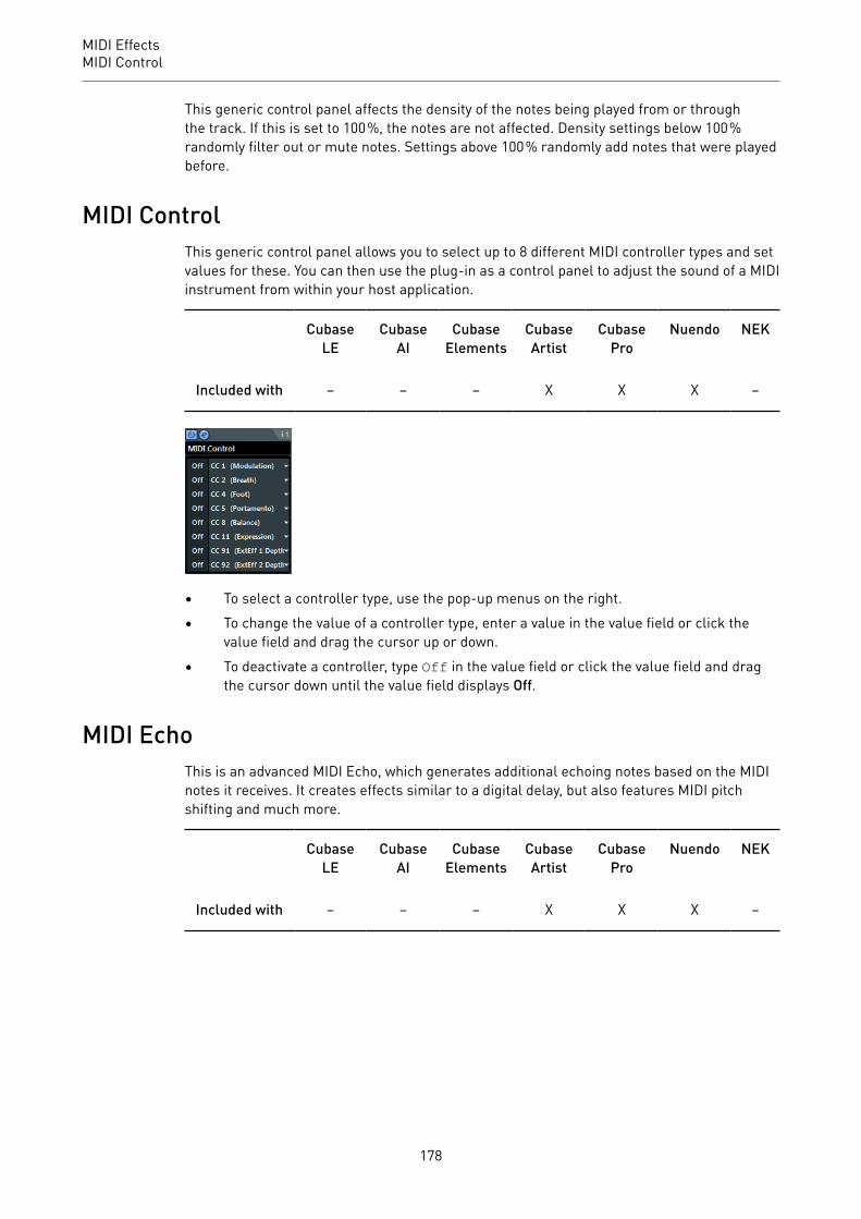
MIDI EffectsMIDI Control
This generic control panel affects the density of the notes being played from or throughthe track. If this is set to 100 %, the notes are not affected. Density settings below 100 %randomly filter out or mute notes. Settings above 100 % randomly add notes that were playedbefore.
MIDI ControlThis generic control panel allows you to select up to 8 different MIDI controller types and setvalues for these. You can then use the plug-in as a control panel to adjust the sound of a MIDIinstrument from within your host application.
CubaseLE
CubaseAI
CubaseElements
CubaseArtist
CubasePro
Nuendo NEK
Included with – – – X X X –
• To select a controller type, use the pop-up menus on the right.• To change the value of a controller type, enter a value in the value field or click the
value field and drag the cursor up or down.• To deactivate a controller, type Off in the value field or click the value field and drag
the cursor down until the value field displays Off.
MIDI EchoThis is an advanced MIDI Echo, which generates additional echoing notes based on the MIDInotes it receives. It creates effects similar to a digital delay, but also features MIDI pitchshifting and much more.
CubaseLE
CubaseAI
CubaseElements
CubaseArtist
CubasePro
Nuendo NEK
Included with – – – X X X –
178
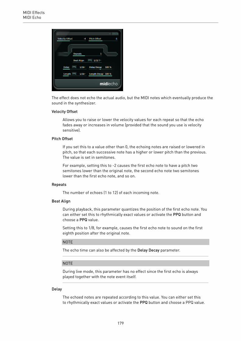
MIDI EffectsMIDI Echo
The effect does not echo the actual audio, but the MIDI notes which eventually produce thesound in the synthesizer.
Velocity Offset
Allows you to raise or lower the velocity values for each repeat so that the echofades away or increases in volume (provided that the sound you use is velocitysensitive).
Pitch Offset
If you set this to a value other than 0, the echoing notes are raised or lowered inpitch, so that each successive note has a higher or lower pitch than the previous.The value is set in semitones.
For example, setting this to -2 causes the first echo note to have a pitch twosemitones lower than the original note, the second echo note two semitoneslower than the first echo note, and so on.
Repeats
The number of echoes (1 to 12) of each incoming note.
Beat Align
During playback, this parameter quantizes the position of the first echo note. Youcan either set this to rhythmically exact values or activate the PPQ button andchoose a PPQ value.
Setting this to 1/8, for example, causes the first echo note to sound on the firsteighth position after the original note.
NOTE
The echo time can also be affected by the Delay Decay parameter.
NOTE
During live mode, this parameter has no effect since the first echo is alwaysplayed together with the note event itself.
Delay
The echoed notes are repeated according to this value. You can either set thisto rhythmically exact values or activate the PPQ button and choose a PPQ value.
179

MIDI EffectsMIDI Echo
This makes it easy to find rhythmically relevant delay values, but still allows forexperimental settings in between.
Delay Decay
Adjusts how the echo time changes with each successive repeat. The value is setas a percentage.
• If this is set to 100 % the echo time is the same for all repeats.• If you raise the value above 100 %, the echoing notes play with gradually
longer intervals, that is, the echo becomes slower.• If you lower the value below 100 %, the echoing notes become gradually
faster, like the sound of a bouncing ball.
Length
Sets the length of the echoed notes. This can either be identical with the lengthof the original notes (parameter set to its lowest value) or the length you specifymanually. You can either set this to rhythmically exact values (displayed as notevalues – see the table below) or activate the PPQ button and choose a PPQ value.
NOTE
The length can also be affected by the Length Decay parameter.
Length Decay
Adjusts how the length of the echoed notes changes with each successive repeat.The higher the setting, the longer the echoed notes.
About Ticks and Note Values
The timing and position-related parameters (Delay, Length, and Beat Align) canall be set in ticks. There are 480 ticks to each quarter note. The parameters allowyou to step between the rhythmically relevant values. The following table showsthe most common note values and the corresponding number of ticks.
Note Value Ticks
1/32 note 60
1/16 note triplet 90
1/16 note 120
1/8 note triplet 160
1/8 note 240
Quarter note triplet 320
Quarter note 480
Half note 960
180

MIDI EffectsMIDI Modifiers
MIDI ModifiersThis plug-in is essentially a duplicate of the MIDI Modifiers section in the Inspector. This canbe useful, for example, if you need extra Random or Range settings.
CubaseLE
CubaseAI
CubaseElements
CubaseArtist
CubasePro
Nuendo NEK
Included with – – – X X X –
The MIDI Modifiers effect also includes the Scale Transpose function that is not availableamong the track parameters.
Scale Transpose
Allows you to transpose each incoming MIDI note, so that it fits within a selected musicalscale. The scale is specified by selecting a key (C, C#, D, etc.) and a scale type (major,melodic or harmonic minor, blues, etc.).
• To deactivate Scale Transpose, select No Scale from the Scale pop-up menu.
MIDI MonitorThis effect monitors incoming MIDI events.
CubaseLE
CubaseAI
CubaseElements
CubaseArtist
CubasePro
Nuendo NEK
Included with – – – X X X –
You can choose whether to analyze live or playback events and which types of MIDI data areto be monitored. Use this, for example, to analyze which MIDI events are generated by a MIDItrack, or to find suspicious events, such as notes with velocity 0 that certain MIDI devicesmight fail to interpreted as note-off events.
181
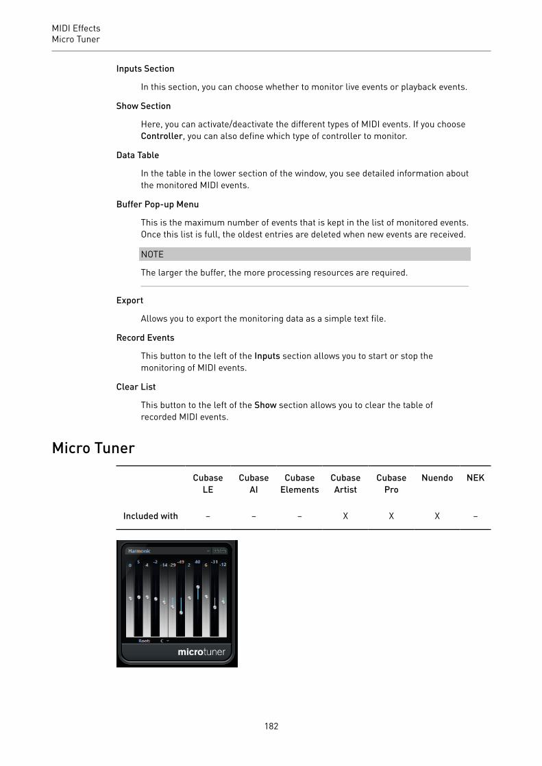
MIDI EffectsMicro Tuner
Inputs Section
In this section, you can choose whether to monitor live events or playback events.
Show Section
Here, you can activate/deactivate the different types of MIDI events. If you chooseController, you can also define which type of controller to monitor.
Data Table
In the table in the lower section of the window, you see detailed information aboutthe monitored MIDI events.
Buffer Pop-up Menu
This is the maximum number of events that is kept in the list of monitored events.Once this list is full, the oldest entries are deleted when new events are received.
NOTE
The larger the buffer, the more processing resources are required.
Export
Allows you to export the monitoring data as a simple text file.
Record Events
This button to the left of the Inputs section allows you to start or stop themonitoring of MIDI events.
Clear List
This button to the left of the Show section allows you to clear the table ofrecorded MIDI events.
Micro Tuner
CubaseLE
CubaseAI
CubaseElements
CubaseArtist
CubasePro
Nuendo NEK
Included with – – – X X X –
182
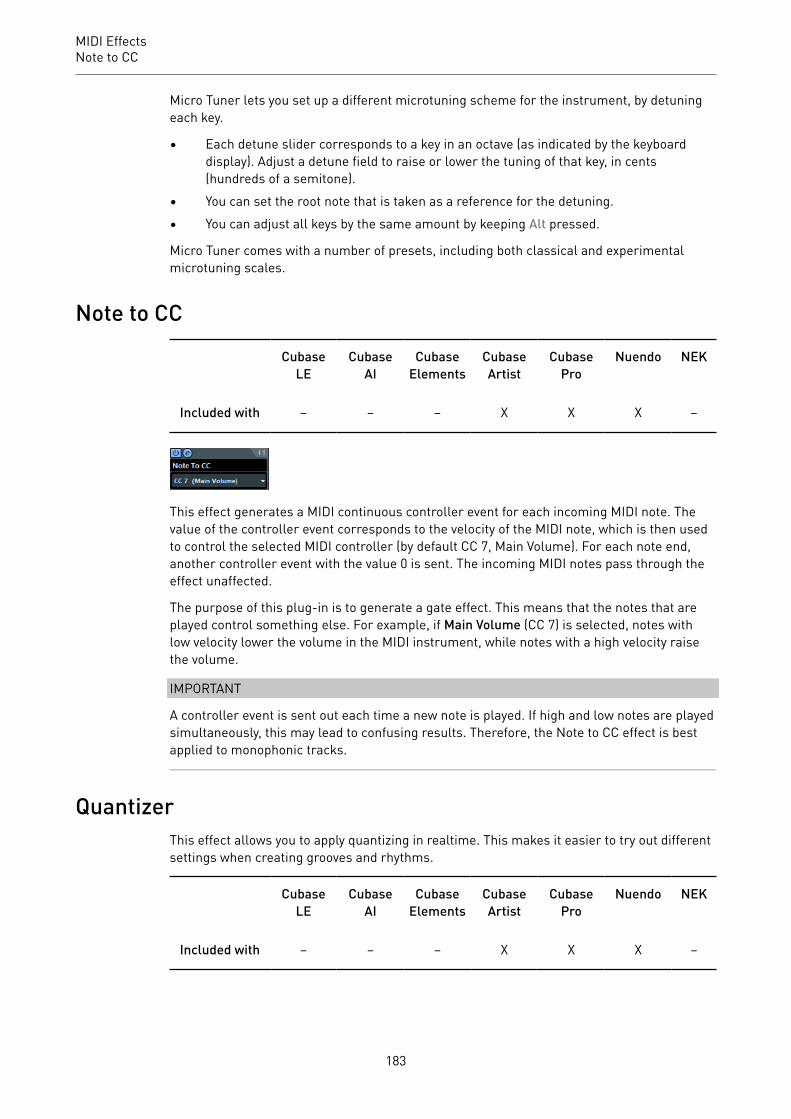
MIDI EffectsNote to CC
Micro Tuner lets you set up a different microtuning scheme for the instrument, by detuningeach key.
• Each detune slider corresponds to a key in an octave (as indicated by the keyboarddisplay). Adjust a detune field to raise or lower the tuning of that key, in cents(hundreds of a semitone).
• You can set the root note that is taken as a reference for the detuning.• You can adjust all keys by the same amount by keeping Alt pressed.
Micro Tuner comes with a number of presets, including both classical and experimentalmicrotuning scales.
Note to CC
CubaseLE
CubaseAI
CubaseElements
CubaseArtist
CubasePro
Nuendo NEK
Included with – – – X X X –
This effect generates a MIDI continuous controller event for each incoming MIDI note. Thevalue of the controller event corresponds to the velocity of the MIDI note, which is then usedto control the selected MIDI controller (by default CC 7, Main Volume). For each note end,another controller event with the value 0 is sent. The incoming MIDI notes pass through theeffect unaffected.
The purpose of this plug-in is to generate a gate effect. This means that the notes that areplayed control something else. For example, if Main Volume (CC 7) is selected, notes withlow velocity lower the volume in the MIDI instrument, while notes with a high velocity raisethe volume.
IMPORTANT
A controller event is sent out each time a new note is played. If high and low notes are playedsimultaneously, this may lead to confusing results. Therefore, the Note to CC effect is bestapplied to monophonic tracks.
QuantizerThis effect allows you to apply quantizing in realtime. This makes it easier to try out differentsettings when creating grooves and rhythms.
CubaseLE
CubaseAI
CubaseElements
CubaseArtist
CubasePro
Nuendo NEK
Included with – – – X X X –
183

MIDI EffectsStepDesigner
Quantizing is a function that changes the timing of notes by moving them towards a quantizegrid. For example, this grid may consist of straight sixteenth notes, in which case the notesall get perfect sixteenth note timing.
NOTE
The main Quantize function in your Steinberg DAW is described in the Operation Manual.
Quantize Note
Sets the note value on which the quantize grid is based. Straight notes, triplets.and dotted notes are available. For example, 16 means straight sixteenth notesand 8T means eighth note triplets.
Swing
Allows you to offset every second position in the grid, creating a swing or shufflefeel. The value is a percentage – the higher you set this, the farther to the rightevery even grid position is moved.
Strength
Determines how close the notes should be moved to the quantize grid. If this isset to 100 %, all notes are forced to the closest grid position. Lowering the settinggradually loosens the timing.
Delay
Sets the delay time in milliseconds. This delay can be automated.
Realtime quantize
During live mode, this option can be used to change the timing of the notes thatare played so that they fit the quantize grid.
StepDesignerStepDesigner is a MIDI pattern sequencer that sends out MIDI notes and additionalcontroller data according to the defined pattern. It does not make use of the incoming MIDI,other than automation data (such as recorded pattern changes).
CubaseLE
CubaseAI
CubaseElements
CubaseArtist
CubasePro
Nuendo NEK
Included with – – – X X X –
184

MIDI EffectsStepDesigner
1. Shift octave up/down2. Shift steps left/right3. Number of steps4. Step size5. Swing6. Controller pop-up menu7. Pattern selector
Creating a Basic PatternPROCEDURE1. Use the Pattern selector to choose which pattern to create.
Each StepDesigner can hold up to 200 different patterns.
2. Use the Step size setting to specify the resolution of the pattern.This setting determines the step length.
3. Specify the number of steps in the pattern with the Number of steps setting.The maximum number of steps is 32. For example, setting Step size to 16 and Numberof steps to 32 creates a 2 bar pattern with sixteenth note steps.
4. Click in the note display to insert notes.You can insert notes on any of the 32 steps, but StepDesigner only plays back thenumber of steps set with the Step size parameter.
• The display spans one octave (as indicated by the pitch list to the left). You canscroll the displayed octave up or down by clicking in the pitch list and draggingup or down.This way you can insert notes at any pitch.
185

MIDI EffectsStepDesigner
• To remove a note from the pattern, click on it again.
NOTEEach step can contain one note only – StepDesigner is monophonic.
RESULT
If you now start playback in your host application, the pattern plays as well, sending out MIDInotes on the track’s MIDI output and channel (or, if you activated StepDesigner as a sendeffect, on the MIDI output and channel selected for the send in the Inspector).
Adding Controller CurvesPROCEDURE1. Open the Controller pop-up menu and select a controller.
The selection is displayed in the lower controller display.
2. Click in the controller display to draw events.The MIDI controller events are sent out during playback along with the notes.
NOTEIf you drag a controller event bar all the way down, no controller value is sent out onthat step.
Setting Up the Controller MenuYou can specify which two controller types (filter cutoff, resonance, volume, etc.) should beavailable on the Controller pop-up menu.
PROCEDURE1. Click Setup.2. Select the controllers that you want to have available in the Controller pop-up menu
and click OK.This selection is global, that is, it applies to all patterns.
Adjusting the Step Length• To make notes shorter, select Gate on the Controller pop-up menu and lower the bars
in the controller display.
186

MIDI EffectsStepDesigner
If a bar is set to its maximum value, the corresponding note is the full length of thestep.
• To make notes longer, you can tie two notes together. This is done by inserting twonotes and clicking in the Tie column for the second note.If 2 notes are tied, the second note is not triggered – the previous note is lengthenedinstead. Also, the second note gets the same pitch as the first note. You can add morenotes and tie them in the same way, creating longer notes.
Other Pattern FunctionsShift Octave up/down
Shift the entire pattern up or down in octave steps.
Shift Steps left/right
Move the pattern one step to the left or right.
Reverse
Reverses the pattern, so that it plays backwards.
Copy/Paste
Allow you to copy the current pattern and paste it in another pattern location (inthe same StepDesigner instance or another).
Reset
Clears the pattern, removing all notes and resetting controller values.
Randomize
Generates a completely random pattern.
Swing
Offsets every second step, creating a swing or shuffle feel. The value is apercentage – the higher you set this, the farther to the right every even step ismoved.
Presets
Allows you to load/save presets for the effect.
NOTE
A stored preset contains all 200 patterns in the StepDesigner.
Automating Pattern ChangesYou can create up to 200 different patterns in each StepDesigner instance.
Typically, you want the pattern selection to change during the project. You can accomplishthis by automating the pattern selector, either in realtime by activating Write automation andswitching patterns during playback or by drawing on the automation track for StepDesigner’sMIDI track.
187

MIDI EffectsTrack Control
Note that you can also press a key on your MIDI keyboard to change patterns. For this, youhave to set up the StepDesigner as an insert effect for a record enabled MIDI track. PressC1 to select pattern 1, C#1 to select pattern 2, D1 to select pattern 3, D#1 to select pattern 4and so on. You can record these pattern changes as note events on a MIDI track.
PROCEDURE1. Select a MIDI track or create a new one and activate StepDesigner as an insert effect.2. Set up several patterns.3. Activate the Record button and press keys on your keyboard to select the
corresponding patterns.The pattern changes are recorded on the MIDI track.
4. Stop recording and play back the MIDI track.
RESULT
You now hear the recorded pattern changes.
NOTE
You can only automate the first 92 patterns.
Track Control
CubaseLE
CubaseAI
CubaseElements
CubaseArtist
CubasePro
Nuendo NEK
Included with – – – X X X –
The Track Control effect contains three control panels for adjusting parameters on a GS orXG compatible MIDI device. The Roland GS and Yamaha XG protocols are extensions of theGeneral MIDI standard, allowing for more sounds and better control of various instrument
188

MIDI EffectsTrack Control
settings. If your instrument is compatible with GS or XG, the Track Controls effect allows youto adjust sounds and effects in your instrument from within your host application.
The Available Control PanelsYou select the control panel from the pop-up menu at the top of the effect panel. Thefollowing panels are available:
GS 1
Contains effect sends and various sound control parameters for use withinstruments compatible with the Roland GS standard.
XG 1
Contains effect sends and various sound control parameters for use withinstruments compatible with the Yamaha XG standard.
XG 2
Global settings for instruments compatible with the Yamaha XG standard.
About the Reset and Off ButtonsYou find two buttons labeled Off and Reset at the top of the control panel:
• Clicking the Off button sets all controls to their lowest value, without sending out anyMIDI messages.
• Clicking the Reset button resets all parameters to their default values, and sends outthe corresponding MIDI messages.
GS 1The following controls are available if the GS 1 Controls mode is selected:
Send 1
Send level for the reverb effect.
Send 2
Send level for the chorus effect.
Send 3
Send level for the variation effect.
Attack
Adjusts the attack time of the sound. Lowering the value shortens the attack,while raising it makes the attack time longer.
Decay
Adjusts the decay time of the sound. Lowering the value shortens the decay,while raising it makes the decay longer.
Release
Adjusts the release time of the sound. Lowering the value shortens the release,while raising it makes the release time longer.
189
MIDI EffectsTrack Control
Cutoff
Adjusts the filter cutoff frequency.
Resonance
Sets the sound characteristic of the filter. With higher values, a ringing sound isheard.
Express
Allows you to send out expression pedal messages on the track’s MIDI channel.
Ch. Press
Allows you to send out aftertouch (channel pressure) messages on the track’sMIDI channel. This is useful if your keyboard cannot send aftertouch, but youhave sound modules that respond to aftertouch.
Breath
Allows you to send breath control messages on the track’s MIDI channel.
Modul.
Allows you to send modulation messages on the track’s MIDI channel.
XG 1The following controls are available if the XG 1 mode is selected.
Send 1
Send level for the reverb effect.
Send 2
Send level for the chorus effect.
Send 3
Send level for the variation effect.
Attack
Adjusts the attack time of the sound. Lowering this value shortens the attack,while raising it makes the attack time longer.
Release
Adjusts the release time of the sound. Lowering this value shortens the release,while raising it makes the release time longer.
Harm.Cont
Adjusts the harmonic content of the sound.
Bright
Adjusts the brightness of the sound.
CutOff
Adjusts the filter cutoff frequency.
190
MIDI EffectsTransformer
Resonance
Sets the sound characteristic of the filter. With higher values, a ringing sound isheard.
XG 2In this mode, the parameters affect global settings in the instruments. Changing one ofthese settings for a track affects all MIDI instruments connected to the same MIDI output,regardless of the MIDI channel setting of the track. Therefore, it might be a good idea tocreate an empty track and use this only for these global settings.
Eff. 1
Allows you to select which type of reverb effect should be used: No effect (reverbdeactivated), Hall 1–2, Room 1–3, Stage 1–2, or Plate.
Eff. 2
Allows you to select which type of chorus effect should be used: No effect (chorusdeactivated), Chorus 1–3, Celeste 1–3, or Flanger 1–2.
Eff. 3
Allows you to select one of a large number of variation effect types. Select NoEffect to deactivate the variation effect.
Reset
Sends an XG reset message.
MastVol
Controls the Master Volume of an instrument. Normally, you should leave this atits highest position and set the volumes individually for each channel (with thevolume faders in the MixConsole or in the Inspector).
TransformerThe Transformer is a realtime version of the Logical Editor. With this you can perform verypowerful MIDI processing on the fly, without affecting the actual MIDI events on the track.
CubaseLE
CubaseAI
CubaseElements
CubaseArtist
CubasePro
Nuendo NEK
Included with – – – X X X –
191
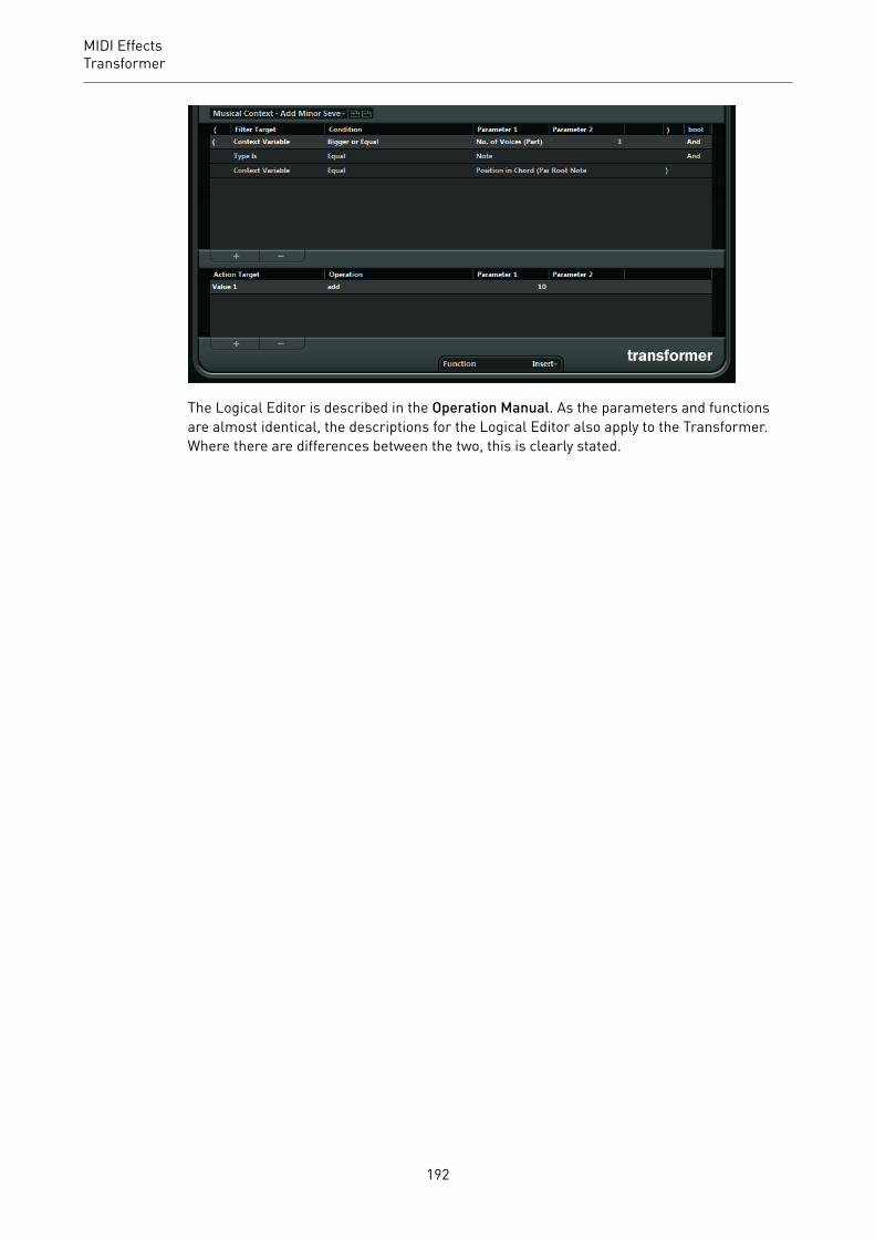
MIDI EffectsTransformer
The Logical Editor is described in the Operation Manual. As the parameters and functionsare almost identical, the descriptions for the Logical Editor also apply to the Transformer.Where there are differences between the two, this is clearly stated.
192
Included VST Instruments
This chapter contains descriptions of the included VST instruments and their parameters.
NOTE
Most of the included instruments are compatible with VST 3. For further information, see theOperation Manual.
Groove Agent SE
CubaseLE
CubaseAI
CubaseElements
CubaseArtist
CubasePro
Nuendo NEK
Included with – X X X X – X
This VST instrument is described in detail in the separate PDF document Groove Agent SE.
HALion Sonic SE
CubaseLE
CubaseAI
CubaseElements
CubaseArtist
CubasePro
Nuendo NEK
Included with X X X X X X –
This VST instrument is described in detail in the separate PDF document HALion Sonic SE.
LoopMash
CubaseLE
CubaseAI
CubaseElements
CubaseArtist
CubasePro
Nuendo NEK
Included with – – – X X X –
193

Included VST InstrumentsLoopMash
LoopMash is a powerful tool for slicing and instant re-assembling of any kind of rhythmicaudio material. With LoopMash, you can preserve the rhythmic pattern of one audio loop, butyou can replace all sounds of this loop with the sounds from up to seven other loops.
LoopMash provides dozens of possibilities to influence the way the slices are re-assembled,thus giving you full control over the results of your performance. You can choose from avariety of effects and apply them to single slices or to your overall performance. Finally, youcan store your configuration as scenes on scene pads, and trigger these scene pads withyour MIDI keyboard.
LoopMash is fully integrated into your host application, which allows you to drag anddrop audio loops from the MediaBay or Project window directly onto the LoopMash panel.Furthermore, you can drag and drop slices from LoopMash to the sample pads of GrooveAgent SE. This allows you to extract certain sounds that you like from LoopMash and usethem with Groove Agent SE.
The LoopMash window has two main areas: the track section in the upper part of the panel,and the parameter section at the bottom.
The selected track is indicated by the background color of the track and the lit button to theleft of the waveform display.
The selected track holds the master loop. The rhythmic pattern of the LoopMash output isgoverned by the master loop – that is, what you hear is the rhythmic pattern of this loop.
On the left of each track, you find the similarity gain sliders. The further to the right youmove the similarity gain slider of a track, the more slices are played back from this track.
194

Included VST InstrumentsLoopMash
Getting StartedTo give you a first impression of what you can do with LoopMash, open the tutorial preset.
PROCEDURE1. In your host application, create an instrument track with LoopMash as the associated
VST instrument.2. In the Inspector for the new track, click the Edit Instrument button to open the
LoopMash panel.3. At the top of the plug-in panel, click on the icon to the right of the preset field and
select Load Preset from the pop-up menu.4. The Presets browser opens, showing presets found in the VST 3 Presets folder for
LoopMash.5. Select the preset called “A Good Start…(Tutorial) 88”.
The preset is loaded into LoopMash.
6. At the bottom of the panel, make sure that the sync button in the transport controls isoff, and start playback by clicking the play button.
7. Look at the 24 pads below the track section: the pad labeled Original is selected.Select the pad named Clap.A new loop is displayed on the second track in the track display, and you hear that thesnare drum sound of the first loop has been replaced with a handclap sound.
8. Select the pad labeled Trio, and then the pad labeled Section. Each time you click, anew loop is added to the mash.Note how the rhythmic pattern of the music stays the same, although an increasingnumber of sounds is taken from the other loops.
9. Select other pads to find out how different parameter settings influence the LoopMashoutput.Some of the pads have the same label, for example, Original and Replaced. The scenesthat are associated with these pads form the basis for variations of that scene. Thevariations of a scene are associated with the scene pads to the right of the originalscene, that is, the scene labeled SliceFX is a variation of the scene labeled Originaland shows an example for the usage of slice effects.
RELATED LINKSLoopMash Parameters on page 197Applying Slice Selection Modifiers and Slice Effects on page 201
How Does LoopMash Work?Whenever you import a loop into LoopMash, the plug-in analyzes the audio material. Itgenerates perceptual descriptors (information on tempo, rhythm, spectrum, timbre, etc.) andthen slices the loop into eighth-note segments.
This means that after you have imported several loops, LoopMash knows the rhythmicpattern of each loop and the location of various sounds that make up this pattern within eachloop. During playback, LoopMash uses the perceptual descriptors to determine how similareach slice is to the current slice of the master track.
195

Included VST InstrumentsLoopMash
NOTE
LoopMash does not categorize the sounds, but looks for overall similarity in the sound.For example, LoopMash might replace a low snare drum sound with a kick drum sound,even though a high snare sound is also available. LoopMash always tries to create a loopacoustically similar to the master loop, but using other sounds.
The similarity is shown by the brightness of each slice on each track, and also by the positionof each slice on the similarity gain slider to the left of each track (if you click a slice, itsposition is highlighted on the similarity gain slider). The brighter a slice, the more similara slice is to the current master track slice, and the further to the right it is displayed on thesimilarity gain slider. Darker slices are less similar and can be found further to the left onthe slider.
The similarity gain settings of the various tracks determine which slice gets playbackpriority. This creates a new loop, over and over again, but with the rhythmic pattern of theoriginal master loop.
In the following figure, you can see four tracks. The track at the top is the master track.During playback, LoopMash moves through the master loop step-by-step (which is indicatedby a rectangle in the track’s color around the current slice) and automatically selects fourslices from these tracks to replace the slices of the master track. The currently playing sliceis indicated by a white rectangle around the slice.
The following figure shows the result of the selection process for each playback step.
1. Master track slices for playback steps 1 to 4.2. Slices 1 to 4 selected for playback.
For best performance, use audio files that have the same sample rate as your project (toavoid sample rate conversion when loading presets or storing scenes).
Experiment with the provided LoopMash presets, and with your own loops of differentlengths and with different rhythms, containing many different sounds – LoopMash is like aninstrument, and we very much encourage you to play it!
196
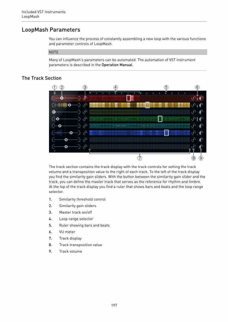
Included VST InstrumentsLoopMash
LoopMash ParametersYou can influence the process of constantly assembling a new loop with the various functionsand parameter controls of LoopMash.
NOTE
Many of LoopMash’s parameters can be automated. The automation of VST instrumentparameters is described in the Operation Manual.
The Track Section
The track section contains the track display with the track controls for setting the trackvolume and a transposition value to the right of each track. To the left of the track displayyou find the similarity gain sliders. With the button between the similarity gain slider and thetrack, you can define the master track that serves as the reference for rhythm and timbre.At the top of the track display you find a ruler that shows bars and beats and the loop rangeselector.
1. Similarity threshold control2. Similarity gain sliders3. Master track on/off4. Loop range selector5. Ruler showing bars and beats6. VU meter7. Track display8. Track transposition value9. Track volume
197

Included VST InstrumentsLoopMash
Importing and Removing LoopsYou can import up to eight audio loops onto the eight tracks in the track display.
PROCEDURE1. Locate the audio loop that you want to import in one of the following locations:
MediaBay and the MediaBay related browsers (for example, the Mini Browser), Projectwindow, Pool, Sample Editor (regions), Audio Part Editor, or the Explorer/Finder.The quickest way to find the LoopMash content is to use the MediaBay: Navigate to theLoopMash content via the VST Sound node.
2. Drag the loop file onto a track in LoopMash.Dragging a loop to a track already occupied replaces the original loop.
RESULT
LoopMash separates the loop into slices, analyzes them, and displays them as a waveformon the track. One track can hold up to 32 slices. If a long loop contains more than 32 slices,LoopMash imports only the first 32. Ideally, you would use a loop file cut at bar boundaries.If you import your file from the MediaBay, LoopMash uses the tempo information supplied bythe MediaBay for the slicing of the loop.
NOTE
To remove a loop from a LoopMash track, right-click the track and select Clear track.
Defining the Master LoopOne track is always selected. This is the master track: it provides the rhythmic pattern thatyou hear. The sounds of this loop are replaced by slices selected from the other loops in thecurrent LoopMash configuration.
PROCEDURE• To make a track the master track, activate the button to the left of it, next to the track
display.
Auditioning Slices
PROCEDURE1. Click on the slice that you want to hear.2. Use the Step function in the transport controls to step through the slices.
RELATED LINKSTransport Controls on page 202
Playback and Master Slice IndicatorsA rectangle in the track color around a slice indicates the current position within themaster loop, that is, the master slice. The slice selected for playback is indicated by a whiterectangle.
198

Included VST InstrumentsLoopMash
Setting a Loop RangeAt the top of the track display, a ruler showing bars and beats (using the project’s timesignature) is displayed. In the ruler, you also find the loop range selector (the bracket) thatdefines the play length.
PROCEDURE1. To shorten the play length, click and drag the handles of the loop range selector (the
bracket) at the top of the track display.This allows you to select even a very small range within your master loop for playback– the rest of the loop is not taken into account.
NOTEShort loop ranges (less than 1 bar) may conflict with the jump interval setting.
2. To change the playback range, click the loop range selector and drag it to a differentposition as a whole.
RELATED LINKSStoring Your Configuration as Scenes on page 203
Setting Track Transposition Value and Track VolumeThe track controls to the right of each track allow you to set a track transposition value andthe track volume for each track individually.
PROCEDURE1. To set a track transposition value, click the button to the right of the track and select a
transposition interval from the pop-up menu.The set value is displayed on the button.
NOTEThis function is tied to the setting for the Slice Timestretch parameter. If SliceTimestretch is deactivated, transposition is created by increasing/decreasing theplayback speed of the slices (transposing a track up by one octave corresponds toplaying the slices twice as fast). With Slice Timestretch on, you get true pitch shifting,that is, there is no change in playback speed.
2. You can change the relative volumes of your tracks with the volume controls on the farright of each track.This is useful for level adjustments between tracks. A VU meter to the left of thevolume control provides visual feedback of the current volume.
RELATED LINKSAudio Parameters on page 205
Setting the SimilarityWith the similarity gain slider (to the left of each track), you determine how important aparticular track is for the mashing up of the master loop. By moving the slider, you specifythat a track is more/less similar to the master track, thus overruling the result of the
199

Included VST InstrumentsLoopMash
LoopMash analysis. As a result, more/less slices from this track are included in the currentmash.
PROCEDURE1. Move the slider to the right to select more slices from the corresponding track for
playback, and to the left to reduce the number of slices for playback.The vertical lines on the similarity gain slider correspond to the slices in this loop. Thechanging pattern of slices indicates similarity of each slice, on all tracks, to the currentmaster track slice. The further to the right a line is, the greater the similarity of thisslice to the master slice.
2. Drag the similarity threshold control (the thin line with handles at the top and bottomintersecting all similarity gain sliders) to the left or right to determine a minimumsimilarity that slices must match to be considered for playback.Slices with a similarity below this threshold are not played.
NOTEOn the Slice Selection page at the bottom of the LoopMash panel, you can makefurther settings for influencing which slices are played.
RELATED LINKSSlice Selection on page 204
Creating Composite TracksLoopMash allows you to build composite tracks.
PROCEDURE1. Import the loop that you want to extract sounds from.2. Audition the slices and drag the slices that you want to use onto an empty track.
A dialog opens asking you to confirm that you want to create a composite track, and todetermine the number of slices that the track contains. If you enter a higher number ofslices than the track actually contains, the track is filled up with empty slices.
3. Click OK.
RESULT
The destination track of the dragged slice becomes composite, indicated by a C to the left ofthe track.
You can use this feature in a very versatile way:
• You can assemble a combination of sounds that you like most on one track.
200

Included VST InstrumentsLoopMash
• You can define a certain rhythmic pattern by combining slices from different loops on acomposite track and making this track the master loop.
• You can use a composite track as a clipboard, allowing you to include sounds frommore than eight loops into your mash.You can use one track for importing and removing the loops that you want to searchfor sounds, and use the remaining seven tracks as composite tracks. This allowsfor including up to 32 sounds from up to 32 different loop files on each of the sevencomposite tracks.
NOTE
Composite tracks are quantized according to the set tempo.
RELATED LINKSTransport Controls on page 202
Applying Slice Selection Modifiers and Slice EffectsRight-clicking a slice opens a context menu where you can influence the selection ofindividual slices and which effect is applied to them. The upper part of the context menushows the slice selection modifiers.
Always
Only available for master track slices. The slice is played always.
Always Solo
Only available for master track slices. The slice is played always and exclusively(independent of the Voices parameter that you set on the Slice Selection page).
Exclude
The slice is never selected for playback.
Boost
Increases the similarity for this particular slice, so that it is played back moreoften.
Below the selection modifiers, the context menu shows the slice effects.
Mute
Mutes the slice.
Reverse
Plays the slice in reverse.
Staccato
Shortens the slice.
Scratch A, B
Plays the slice as if scratched.
Backspin 4
Simulates a turntable backspin lasting over 4 slices.
201
Included VST InstrumentsLoopMash
Slowdown
Applies a slowdown.
Tapestart
Simulates a tapestart, that is, speeds the slice up.
Tapestop 1, 2
Simulates a tapestop, that is, slows the slice down.
Slur 4
Stretches the slice over 4 slice lengths.
Slur 2
Stretches the slice over 2 slice lengths.
Stutter 2, 3, 4, 6, 8
Plays only the initial portion of a slice, and repeats it 2, 3, 4, 6, or 8 times duringone slice length, respectively.
RELATED LINKSSlice Selection on page 204Performance Controls on page 206
Transport Controls
The transport controls can be found at the bottom of the LoopMash panel.
Play
Click the Play button to start or stop playback.
Locate
Click the Locate button to return to the beginning of the loop (bar 1/beat 1).Playback always starts automatically when clicking this button.
Step left/right
Clicking the Step left/right button steps backwards/forwards through thetimeline, playing one slice at a time.
Setting the LoopMash TempoDuring playback, LoopMash can be synchronized to the tempo set in your host application, orcan follow its own tempo setting.
• Activate the sync button (to the right of the Play button) to synchronize LoopMash tothe project tempo set in your host application.If sync is activated, you can start playback using the transport controls of your hostapplication. With sync deactivated, LoopMash starts playing when you click the Playbutton in LoopMash.
202
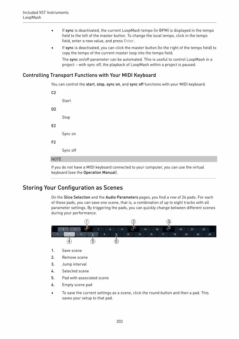
Included VST InstrumentsLoopMash
• If sync is deactivated, the current LoopMash tempo (in BPM) is displayed in the tempofield to the left of the master button. To change the local tempo, click in the tempofield, enter a new value, and press Enter.
• If sync is deactivated, you can click the master button (to the right of the tempo field) tocopy the tempo of the current master loop into the tempo field.The sync on/off parameter can be automated. This is useful to control LoopMash in aproject – with sync off, the playback of LoopMash within a project is paused.
Controlling Transport Functions with Your MIDI KeyboardYou can control the start, stop, sync on, and sync off functions with your MIDI keyboard.
C2
Start
D2
Stop
E2
Sync on
F2
Sync off
NOTE
If you do not have a MIDI keyboard connected to your computer, you can use the virtualkeyboard (see the Operation Manual).
Storing Your Configuration as ScenesOn the Slice Selection and the Audio Parameters pages, you find a row of 24 pads. For eachof these pads, you can save one scene, that is, a combination of up to eight tracks with allparameter settings. By triggering the pads, you can quickly change between different scenesduring your performance.
1. Save scene2. Remove scene3. Jump interval4. Selected scene5. Pad with associated scene6. Empty scene pad
• To save the current settings as a scene, click the round button and then a pad. Thissaves your setup to that pad.
203

Included VST InstrumentsLoopMash
• To recall a scene, click the corresponding scene pad.• To remove a scene from a pad, click the x button and then a pad.• To edit a scene pad label, double-click on the scene pad and enter a name.• To rearrange the scene pads, click on a scene pad and drag it to a new position.
IMPORTANT
Once you have set up a LoopMash configuration, save it to a scene pad. Changing sceneswithout saving means discarding any unsaved changes.
Setting a Jump IntervalYou can determine the point at which LoopMash changes to the next scene during playbackwhen you trigger a pad.
PROCEDURE• Click the Jump interval button and select an option from the pop-up menu.
RESULT
NOTE
The option e: End means that the current loop is played to the end before switching scenes.When you set up a short loop range, you may need to set the interval to e: End to ensure thatthe jump point is reached.
Triggering Scene Pads with Your MIDI KeyboardThe scene pads are arranged according to the keys on a MIDI keyboard. You can trigger the24 scene pads with a connected MIDI keyboard starting from C0 and ending with B1.
Slice SelectionClick the Slice Selection button (above the transport controls) to open the Slice Selectionpage. The options on this page allow you to further influence which slices are selected forplayback.
Number of Voices
Here you can set the total number of slices from all tracks that replace themaster slice (according to the current similarity gain settings). The range is fromone (left) to four (right) voices, that is, sounds from up to four loops can playsimultaneously. Increasing the number of voices increases the CPU load.
Voices per Track
This is the maximum number of slices that can be selected from a single track.The range is from one to four. The fewer slices can be picked from the sametrack, the more variety you get in the LoopMash output.
Selection Offset
Move this slider to the right to allow slices that are less similar to be selected forplayback. This setting affects all tracks of this scene.
204

Included VST InstrumentsLoopMash
Random Selection
Move this slider to the right to allow more variation when selecting slices forplayback, adding a more random feel to the selection process. This settingaffects all tracks of this scene.
Selection Grid
Determines how often LoopMash looks for similar slices during playback: always(left position), or only every 2nd, 4th, or 8th (right position) step. For example, ifyou set the Selection Grid to every 8th step (right position), LoopMash replacessimilar slices every 8th step. Between two replacement steps it plays backthe tracks of the slices that have been selected in the last replacement step,resulting in longer playback sequences on one track.
Similarity Method
Here, you can modify the criteria that LoopMash considers when comparing theslices for similarity. There are three similarity methods:
• Standard – This is the standard method, where all slices on all tracks arecompared and various characteristics regarding rhythm, tempo, spectrum,etc. are taken into account.
• Relative – This method does not only consider the overall similarity of allslices on all tracks, but also takes the relation to the other slices on thesame track into account. For example, LoopMash can replace the loudest,lowest sound on one track with the loudest, lowest sound on another track.
• Harmonic – This method only takes the analyzed tonal information intoaccount, so that a slice is replaced by a harmonically similar slice, ratherthan by a rhythmically similar slice. With this method, also the tracktransposition value is considered, that is, a master slice with a C majorchord is not replaced by a slice with a D major chord. But it is replaced ifyou set the transposition value of the track of the slice with the D majorchord to -2. It is advisable to keep the similarity gain sliders in a lowposition when you work with this method, because otherwise you mayproduce disharmonies. You can modify the transposition values to playback more slices of a specific track.
RELATED LINKSStoring Your Configuration as Scenes on page 203
Audio ParametersClick the Audio Parameters button (above the transport controls) to open the AudioParameters page. With the options on this page, you can influence the sound of theLoopMash audio output.
Adapt Mode
With this mode, you can adapt the sound of the selected slice to the sound of themaster slice. The available options are:
• Volume – changes the overall volume of the selected slice.• Envelope – modifies volume changes within the slice.• Spectrum – modifies the spectrum of the slice (equalization).
205

Included VST InstrumentsLoopMash
• Env + Spectrum – this is a combination of the Envelope and Spectrummodes.
Adapt Amount
Move this slider to the right to increase the adaptation specified with the AdaptMode parameter.
Slice Quantize
Move this slider to the right to apply quantizing to the slices, that is, the slicesare aligned to an eighth-note grid. If the slider is all the way to the left, the slicesfollow the rhythmic pattern defined by the original master loop.
Slice Timestretch
Allows you to apply realtime timestretching to the slices, filling gaps or avoidingoverlaps between slices that are not played back at their original tempo, orwhen combining slices with different original tempos. Applying timestretchincreases the CPU load and may affect the sound quality. Reduce the need fortimestretching by using loops with similar original tempos.
Staccato Amount
If you move this slider to the right, the length of the slices is gradually reduced,giving the output a staccato feel.
Dry/Wet Mix
Sets the balance between the volumes of the master loop and the selected slicesfrom the other tracks.
RELATED LINKSSetting Track Transposition Value and Track Volume on page 199
Performance Controls
Click the Performance Controls button to open the Performance Controls page. On thispage, you find a row of buttons that are arranged according to the keys on a MIDI keyboard.
• By clicking these buttons during playback, you can apply effects to your overallperformance.An effect is applied as long as the button is activated.
Most of the available effects correspond to the effects that you can apply to single slices, withthe green buttons corresponding to the stutter and slur effects and the red buttons to theMute, Reverse, Staccato effects, etc.
NOTE
Effects triggered with the Performance Controls buttons override the slice effects.
With the blue buttons and the yellow button, you can apply additional effects that cannot beapplied to single slices:
206

Included VST InstrumentsMystic
Cycle 4, 2, 1
Sets up a short cycle over 4, 2, and 1 slices, respectively. This short cycle isalways set up within the loop range that is set in the ruler. Setting up a cycle over1 slice means that this slice is repeated until you release the button.
Continue
Plays back the tracks of the selected slices continuously until you release thebutton.
NOTE
You cannot save global effects in scenes. To apply effects and save them in scenes, use sliceeffects.
Triggering the Performance Controls with Your MIDI KeyboardYou can trigger the Performance Controls with your MIDI keyboard starting from C3 upwards.
RELATED LINKSApplying Slice Selection Modifiers and Slice Effects on page 201
Mystic
CubaseLE
CubaseAI
CubaseElements
CubaseArtist
CubasePro
Nuendo NEK
Included with – – – X X – X
207

Included VST InstrumentsMystic
The synthesis method used by Mystic is based on three parallel comb filters with feedback.A comb filter is a filter with a number of notches in its frequency response, with the notchfrequencies harmonically related to the frequency of the fundamental (lowest) notch.
A typical example of comb filtering occurs if you are using a flanger effect or a delay effectwith very short delay time. Raising the feedback (the amount of signal sent back into thedelay or flanger) causes a resonating tone – this tone is basically what the Mystic produces.This synthesis method is capable of generating a wide range of sounds, from gentle plucked-string tones to weird, non-harmonic timbres.
The basic principle is the following:
• You start with an impulse sound, typically with a very short decay.The spectrum of the impulse sound largely affects the tonal quality of the final sound.
• The impulse sound is fed into the three comb filters, in parallel. Each of these has afeedback loop.This means the output of each comb filter is fed back into the filter. This results in aresonating feedback tone.
• When the signal is fed back into the comb filter, it goes via a separate, variable low-pass filter.This filter corresponds to the damping of high frequencies in a physical instrument –if this is set to a low cutoff frequency it causes high harmonics to decay faster than thelower harmonics (as when plucking a string on a guitar, for example).
• The level of the feedback signal is governed by a feedback control.This determines the decay of the feedback tone. Setting this to a negative valuesimulates the traveling wave in a tube with one open end and one closed end. Theresult is a more hollow, square wave-like sound, pitched one octave lower.
208

Included VST InstrumentsMystic
• A detune control offsets the fundamental frequencies of the three comb filters, forchorus-like sounds or drastic special effects.
Finally you have access to the common synth parameters – two LFOs, four envelopes and aneffect section.
• By default, envelope 2 controls the level of the impulse sound – this is where you setup the short impulse decay when emulating string sounds, etc.
RELATED LINKSMystic Diagram on page 252
Sound Parameters
The Impulse Control Section
This is where you set up the impulse sound – the sound fed into the comb filters, servingas a starting point for the sound. The Impulse Control has two basic waveforms that arefiltered through separate spectrum filters with adjustable base frequency. The output is anadjustable mix between the two waveform/spectrum filter signals.
Spectrum Displays
The displays allow you to draw a filter contour with your mouse for spectrum filters A and B.
• To set up the contour, click in one of the displays and drag the mouse to draw a curve.This produces the inverse contour in the other display, for maximum sonic versatility.To set up the contour independently for the two filters, hold down Shift and click anddrag the mouse in either display.
• Use the Preset pop-up menu to select a preset contour.• If you want to calculate a random spectrum filter curve, you can choose the Randomize
function from the Preset pop-up menu.Each time you choose this function, a new randomized spectrum appears.
209

Included VST InstrumentsMystic
Waveform Pop-up Menu
The pop-up menu at the bottom of the waveform section (the central box at the top of thepanel) allows you to select a basic waveform to be sent through filter contour A. The optionsare especially suited for use with the spectrum filter.
Cut
Offsets the frequency of the filter contour, working somewhat like a cutoff controlon a standard synth filter. To use the filter contour in its full frequency range, setCut to its maximum value.
Morph
Adjusts the mix between the two signal paths: waveform A spectrum contour Aand waveform B spectrum contour B.
Coarse
Offsets the pitch for the impulse sound. In a typical string setup, when theimpulse sound is very short, this does not change the pitch of the final sound, butthe tonal color.
Raster
This removes harmonics from the impulse sound. As the harmonic content of theimpulse sound is reflected in the comb filter sound, this changes the final timbre.
Comb Filter Sound Parameters
Damping
This is a 6 dB/oct low-pass filter that affects the sound being fed back into thecomb filters. This means the sound becomes gradually softer when decaying,that is, high harmonics decay faster than the lower harmonics (as when pluckinga string on a guitar, for example).
• The lower the Damping, the more pronounced this effect.If you open the filter completely (turn Damping up to max) the harmoniccontent is static – the sound does not get softer when decaying.
210
Included VST InstrumentsMystic
Level
Determines the level of the impulse sound being fed into the comb filters. Bydefault, this parameter is modulated by envelope 2. That is, you use envelope 2 asa level envelope for the impulse sound.
• For a string-type sound, you want an envelope with a quick attack, a veryshort decay and no sustain (an impulse in other words), but you can alsouse other envelopes for other types of sounds.Try raising the attack for example, or raising the sustain to allow theimpulse sound to be heard together with the comb filter sound.
Crackle
Allows you to send noise directly into the comb filters. Small amounts of noiseproduce a crackling, erratic effect, higher amounts give a more pronounced noisesound.
Feedback
Determines the amount of signal sent back into the comb filters (the feedbacklevel).
• Setting Feedback to zero (twelve o’clock) effectively turns off the combfilter sound, as no feedback tone is produced.
• Setting Feedback to a positive value creates a feedback tone, with highersettings generating longer decays.
• Setting Feedback to a negative value creates a feedback tone with a morehollow sound, pitched one octave lower. Lower settings generate longerdecays.
Detune
Offsets the notch frequencies of the three parallel comb filters, effectivelychanging the pitches of their feedback tones. At low settings, this creates achorus-like detune effect. Higher settings detunes the three tones in widerintervals.
Pitch and Fine
Overall pitch adjustment of the final sound. This changes the pitch of both theimpulse sound and the final comb filter sound.
Key Tracking
Determines whether the impulse sound should track the keyboard. This affectsthe sound of the comb filters in a way similar to a key track switch on a regularsubtractive synth filter.
Portamento
Makes the pitch glide between the notes you play. The parameter settingdetermines the time it takes for the pitch to glide from one note to the next. Turnthe knob clockwise for longer glide time.
The Mode switch allows you to apply glide only when you play a legato note(switch is set to Legato). Legato is when you play a note without releasing thepreviously played note. Note that Legato mode only works with monophonicparts.
211

Included VST InstrumentsMystic
Master Volume and Pan
The master Volume knob controls the master volume (amplitude) of the instrument. Bydefault, this parameter is controlled by Envelope 1, to generate an amplitude envelope forthe oscillators.
The Pan knob controls the position of the instrument in the stereo spectrum. You can usePan as a modulation destination.
Modulation and ControllersThe lower half of the control panel displays the various modulation and controllerassignment pages available, as well as the EFX page. You switch between these pages usingthe buttons above this section.
The following pages are available:
• The LFO page has two low frequency oscillators (LFOs) for modulating parameters.• The ENV page contains the four envelope generators that can be assigned to control
parameters.• The Event page contains the common MIDI controllers (Mod wheel, Aftertouch, etc.)
and their assignments.• The EFX page offers three separate effect types: Distortion, Delay, and Modulation.
RELATED LINKSEnvelope Page on page 215Event Page on page 217Effects (EFX) Page on page 218
LFO PageThe LFO page is opened by clicking the LFO button at the top of the lower half of the controlpanel. The page contains all parameters and the modulation and velocity destinations for twoindependent LFOs.
Depending on the selected preset, there may already be modulation destinations assigned, inwhich case these are listed in the Mod Dest box for each LFO.
A low frequency oscillator (LFO) is used for modulating parameters, for example the pitch ofan oscillator (to produce vibrato), or for any parameter where cyclic modulation is required.
212
Included VST InstrumentsMystic
The two LFOs have identical parameters.
Speed
Governs the rate of the LFO. If the sync mode is set to MIDI, the available ratevalues are selectable as note values, so the rate is synchronized to the sequencertempo.
Depth
Controls the amount of modulation applied by the LFO. If this is set to zero, nomodulation is applied.
Waveform
Sets the LFO waveform.
Sync mode (Part/MIDI/Voice/Key)
Sets the sync mode for the LFO.
RELATED LINKSAssigning LFO Modulation Destinations on page 214
About the Sync ModesThe Sync modes determine how the LFO cycle affects the notes you play.
Part
In this mode, the LFO cycle is free running and affects all the voices in sync. Freerunning means that the LFO cycles continuously, and does not reset when a noteis played.
MIDI
In this mode, the LFO rate is synced in various beat increments to MIDI clock.
Voice
In this mode, each voice in the Part has its own independent LFO cycle (the LFO ispolyphonic). These cycles are also free running – each key down starts anywherein the LFO cycle phase.
Key
Same as Voice except that it is not free running – for each key down the LFO cyclestarts over.
About the WaveformsMost standard LFO waveforms are available for LFO modulation. You use sine and trianglewaveforms for smooth modulation cycles, square and ramp up/down for different typesof stepped modulation cycles and random or sample for random modulation. The samplewaveform is different:
• In this mode, the LFO makes use of the other LFO as well.For example, if LFO 2 is set to use Sample, the resulting effect also depends on thespeed and waveform of LFO 1.
213

Included VST InstrumentsMystic
Assigning LFO Modulation DestinationsYou can assign a modulation destination for an LFO.
PROCEDURE1. Click in the Mod Dest box for one of the LFOs.
A pop-up menu appears in which all possible modulation destinations are shown. AllSound parameters as well as most LFO and Envelope parameters are available asdestinations.
2. Select a destination, for example, Cut.The selected modulation destination is now shown in the list. Beside the destination, adefault value (50) has been set. The value represents the modulation amount.
• You can set positive and negative modulation values by clicking on the value inthe list, typing in a new value, and pressing Enter.
To enter negative values, type a minus sign followed by the value.
3. Select a suitable LFO Waveform, Speed, Depth, and Sync mode.You should now hear the Cut parameter being modulated by the LFO.
4. Using the same basic method, you can add any number of modulation destinations forthe LFO.They are all listed in the Mod Dest box.
• To remove a modulation destination, click on its name in the list and select Offfrom the pop-up menu.
Assigning LFO Velocity DestinationsYou can also assign velocity-controlled LFO modulation.
PROCEDURE1. Click in the Vel Dest box for one of the LFOs.
A pop-up menu appears in which all possible velocity destinations are shown.
2. Select a destination.The selected velocity destination is now shown in the list. Beside the destination, adefault value (50) has been set. The value represents the modulation amount.
• You can set positive and negative values by clicking on the value in the list, typingin a new value, and pressing Enter.
To enter negative values, type a minus sign followed by the value.
3. Using the same basic method, you can add any number of velocity destinations for theLFO.
214

Included VST InstrumentsMystic
They are all listed in the Vel Dest box.
• To remove a velocity destination, click on its name in the list and select Off fromthe pop-up menu.
LFO modulation velocity controlIf you follow the steps above and select the Cut parameter as a Velocity destination, thefollowing happens:
• The harder you strike the key, the more the Cut parameter is modulated by the LFO.• If you enter a negative value for the velocity modulation amount, the opposite happens:
the harder you play, the less the Cut parameter is modulated by the LFO.
Envelope PageThe Envelope page is opened by clicking the ENV button at the top of the lower half of thecontrol panel. The page contains all parameters and the modulation and velocity destinationsfor the four independent envelope generators.
Envelope generators govern how a parameter value changes when a key is pressed, when akey is held and finally when a key is released.
On the Envelope page, the parameters for one of the four envelope generators is shown at atime.
• You switch between the four envelopes in the section to the left.Clicking on either of the four mini curve displays selects it and displays thecorresponding envelope parameters to the right.
• Envelope generators have four parameters: Attack, Decay, Sustain, and Release(ADSR).
• You can set envelope parameters in 2 ways: by using the sliders or by clicking anddragging the curve in the Envelope curve display.You can also do this in the mini curve displays.
• By default, Envelope 1 is assigned to the master volume, and therefore acts as anamplitude envelope. The amplitude envelope adjusts how the volume of the soundchanges from the time you press a key until the key is released.If no amplitude envelope is assigned, there is no output.
• Envelope 2 is by default assigned to the Level parameter.
The Envelope parameters are as follows:
Attack
The attack phase is the time it takes from zero to the maximum value. Howlong this takes is governed by the Attack setting. If the Attack is set to 0, the
215

Included VST InstrumentsMystic
maximum value is reached instantly. If this value is raised, it takes time beforethe maximum value is reached. Range is from 0.0 milliseconds to 91.1 seconds.
Decay
After the maximum value has been reached, the value starts to drop. How longthis takes is governed by the Decay parameter. The Decay has no effect if theSustain parameter is set to maximum.
Sustain
Determines the level for the envelope after the Decay phase. Note that Sustainrepresents a level, whereas the other envelope parameters represent times.
Release
Determines the time it takes for the value to fall back to zero after releasing thekey. Range is from 0.0 milliseconds to 91.1 seconds.
Punch
If Punch is activated, the start of the decay phase is delayed a few milliseconds,that is, the envelope stays at top level for a moment before moving on to thedecay phase. The result is a punchier attack similar to a compressor effect. Thiseffect is more pronounced with short attack and decay times.
Retrigger
If Retrigger is activated, the envelope retriggers each time you play a new note.However, with certain textures/pad sounds and a limited number of voices, itis recommended to leave the button deactivated, due to click noises that mightoccur.
Assigning Envelope Modulation DestinationsYou can assign a modulation destination for an envelope.
PROCEDURE1. Click in the Mod Dest box for one of the envelopes.
A pop-up menu appears in which all possible modulation destinations are shown. AllSound parameters as well as most LFO and Envelope parameters are available asdestinations.
2. Select a destination, for example, Cut.The selected modulation destination is now shown in the list. Beside the destination, adefault value (50) has been set. The value represents the modulation amount.
• You can set positive and negative modulation values by clicking on the value inthe list, typing in a new value, and pressing Enter.To enter negative values, type a minus sign followed by the value.
3. Select a suitable envelope curve for the modulation.You should now hear the Cut parameter being modulated by the envelope as you play.
4. Using the same basic method, you can add any number of modulation destinations forthe envelope.They are all listed in the Mod Dest box.
216

Included VST InstrumentsMystic
• To remove a modulation destination, click on its name in the list and select Offfrom the pop-up menu.
Assigning Envelope Velocity DestinationsYou can also assign velocity-controlled envelope modulation, that is, the modulation isgoverned by how hard or soft you strike a key.
PROCEDURE1. Click in the Vel Dest box for one of the envelopes.
A pop-up menu appears in which all possible velocity destinations are shown.
2. Select a destination.The selected velocity destination is now shown in the list. Beside the destination, adefault value (50) has been set. The value represents the modulation amount. Seebelow for an example of how velocity modulation works.
• You can set positive and negative values by clicking on the value in the list, typingin a new value, and pressing Enter.To enter negative values, type a minus sign followed by the value.
3. Using the same basic method, you can add any number of velocity destinations for theEnvelope.They are all listed in the Vel Dest box.
• To remove a velocity destination, click on its name in the list and select Off fromthe pop-up menu.
Envelope modulation velocity controlIf you follow the steps above and select the Cut parameter as a Velocity destination, thefollowing happens:
• The harder you strike the key, the more the parameter is modulated by the envelope.• If you enter a negative value for the velocity modulation amount, the opposite happens;
the harder you play the less the Cut parameter is modulated by the Envelope.
Event PageThe Event page is opened by clicking the EVENT button at the top of the lower half of thecontrol panel. This page contains the most common MIDI controllers and their assignments.
Modulation Wheel
The modulation wheel on your keyboard can be used to modulate parameters.
217

Included VST InstrumentsMystic
Velocity
Controls parameters according to how hard or soft you play notes on yourkeyboard. A common application of velocity is to make sounds brighter andlouder if you strike the key harder.
Aftertouch
Aftertouch, or channel pressure, is MIDI data sent when pressure is appliedto a keyboard after the key has been struck, and while it is being held down orsustained. Aftertouch is often routed to control filter cutoff, volume, and otherparameters to add expression.
Key Pitch Tracking
This can change parameter values linearly according to where on the keyboardyou play.
Assign a Controller to a Parameter
PROCEDURE1. Click in the Mod Dest box for one of the controllers.
A pop-up menu appears in which all possible modulation destinations are shown. AllSound parameters as well as most LFO and Envelope parameters are available asdestinations.
2. Select a destination.The selected modulation destination is now shown in the list. Beside the destination, adefault value (50) has been set. The value represents the modulation amount when thecontroller is at its full range.
• You can set positive and negative modulation values by clicking on the value inthe list, typing in a new value, and pressing Enter.To enter negative values, type a minus sign followed by the value.
3. Using the same basic method, you can add any number of modulation destinations forthe controllers.They are all listed in the Mod Dest box for each controller.
• To remove a modulation destination, click on its name in the list and select Offfrom the pop-up menu.
Effects (EFX) PageThis page features three separate effect units: Distortion, Delay, and Modulation (Phaser/Flanger/Chorus). The Effect page is opened by clicking the EFX button at the top of the lowerhalf of the control panel.
218
Included VST InstrumentsMystic
• Each separate effect section is laid out with a row of buttons that determine the effecttype or characteristic and a row of sliders for making parameter settings.
• To activate an effect, click the Active button so that a dot appears.Clicking again deactivates the effect.
DistortionYou can choose between 4 basic distortion characteristics:
• Distortion provides hard clipping distortion.• Soft Distortion provides soft clipping distortion.• Tape Emulation produces distortion similar to magnetic tape saturation.• Tube Emulation produces distortion similar to valve amplifiers.
Drive
Sets the amount of distortion by amplifying the input signal.
Filter
Sets the crossover frequency of the distortion filter. The distortion filter consistsof a low-pass filter and a high-pass filter with a cutoff frequency equal to thecrossover frequency.
Tone
Controls the relative amount of low-pass and high-pass filtered signal.
Level
Controls the output level of the effect.
DelayYou can choose between 3 basic delay characteristics:
• Stereo Delay has two separate delay lines panned left and right.• In Mono Delay, the two delay lines are connected in series for monophonic dual tap
delay effects.• In Cross Delay, the delayed sound bounces between the stereo channels.
Song Sync
Activates/Deactivates tempo sync of the delay times.
Delay 1
Sets the delay time ranging from 0 ms to 728 ms. If MIDI sync is activated, therange is from 1/32 to 1/1; straight, triplet or dotted.
Delay 2
Same as Delay 1.
Feedback
Controls the decay of the delays. With higher settings, the echoes repeat longer.
219

Included VST InstrumentsMystic
Filter
A low-pass filter is built into the feedback loop of the delay. This parametercontrols the cutoff frequency of this feedback filter. Low settings result insuccessive echoes sounding darker.
Level
Controls the output level of the effect.
ModulationYou can choose between 3 basic modulation characteristics:
• Phaser uses an 8-pole all-pass filter to produce the classic phasing effect.• Flanger is composed of two independent delay lines with feedback for the left and the
right channel. The delay time of both delays is modulated by one LFO with adjustablefrequency.
• Chorus produces a rich chorus effect with 4 delays modulated by four independentLFOs.
Song Sync
Activates/Deactivates tempo sync of the Rate parameter.
Rate
Sets the rate of the LFOs modulating the delay time. If Song Sync is activated, therate is synchronized to various beat increments.
Depth
Controls the depth of the delay time modulation.
Delay
Sets the delay time of the four delay lines.
Feedback
Controls the amount of positive or negative feedback for all four delay lines.
Level
Controls the output level of the effect.
SR ParametersWith these buttons, you can change the sample rate. Lower sample rates basically reducethe high frequency content and sound quality, but the pitch is not altered. This is useful toemulate the lo-fi sounds of older digital synths.
• If the F button is active, the program of the selected part plays back with the samplerate set in the host application.
• If the 1/2 button is active, the program of the selected part plays back with half theoriginal sample rate.
• If the 1/4 button is active, the program of the selected part plays back with a quarter ofthe original sample rate.
220
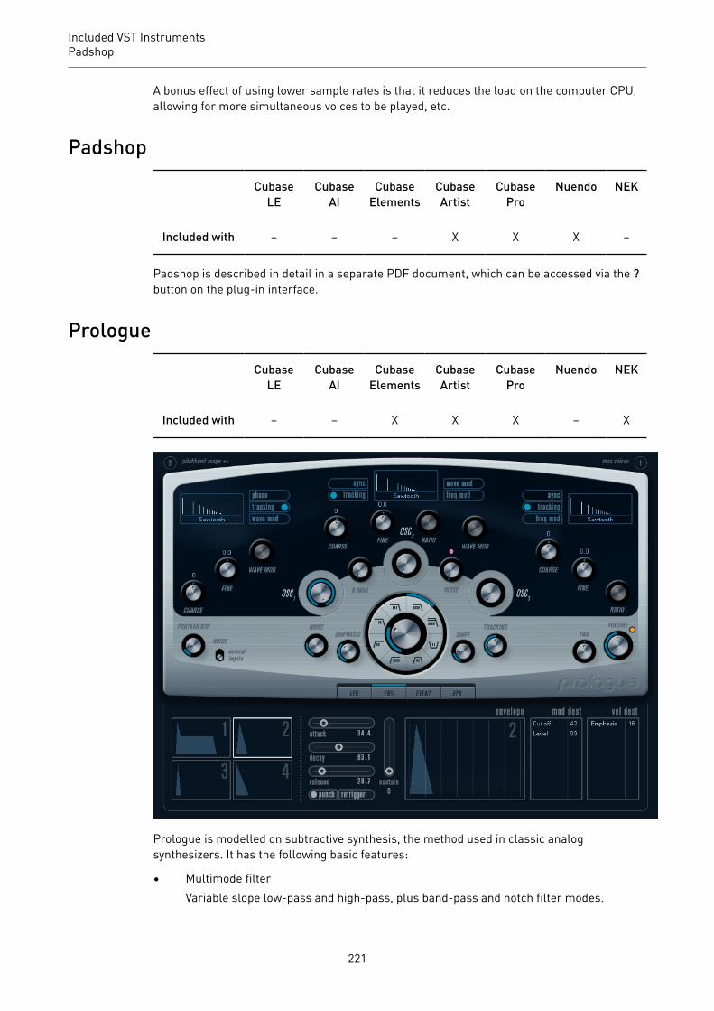
Included VST InstrumentsPadshop
A bonus effect of using lower sample rates is that it reduces the load on the computer CPU,allowing for more simultaneous voices to be played, etc.
Padshop
CubaseLE
CubaseAI
CubaseElements
CubaseArtist
CubasePro
Nuendo NEK
Included with – – – X X X –
Padshop is described in detail in a separate PDF document, which can be accessed via the ?button on the plug-in interface.
Prologue
CubaseLE
CubaseAI
CubaseElements
CubaseArtist
CubasePro
Nuendo NEK
Included with – – X X X – X
Prologue is modelled on subtractive synthesis, the method used in classic analogsynthesizers. It has the following basic features:
• Multimode filterVariable slope low-pass and high-pass, plus band-pass and notch filter modes.
221

Included VST InstrumentsPrologue
• Three oscillators, each with 4 standard waveforms plus an assortment of specializedwaveforms.
• Frequency modulation.• Ring Modulation.• Built-in effects.• Prologue receives MIDI on all MIDI channels.
You do not have to select a MIDI channel to direct MIDI to the Prologue.
RELATED LINKSAbout the Filter Types on page 228Selecting Waveforms on page 222About Frequency Modulation on page 226Ring Modulation on page 227Effects (EFX) Page on page 218Functional Diagrams on page 252
Sound Parameters
Oscillator Section
This section contains parameters affecting the 3 oscillators. These are located in upper halfof the instrument panel.
Selecting WaveformsEach oscillator has a number of waveforms that can be selected by clicking on the waveformname in the box located in each oscillator section.
222

Included VST InstrumentsPrologue
Sawtooth
This waveform contains all harmonics and produces a bright and rich sound.
Parabolic
This can be described as a rounded sawtooth waveform, producing a softertimbre.
Square
Square waveforms only contain odd number harmonics, which produces adistinct, hollow sound.
Triangle
The triangle waveform generates only a few harmonics, spaced at odd harmonicnumbers, which produces a slightly hollow sound.
Sine
The sine wave is the simplest possible waveform, with no harmonics (overtones).The sine wave produces a neutral, soft timbre.
Formant 1–12
Formant waveforms emphasizes certain frequency bands. Like the humanvoice, musical instruments have a fixed set of formants, which give it a unique,recognizable tonal color or timbre, regardless of pitch.
Vocal 1–7
These are also formant waveforms, but specifically vocal-oriented. Vowel sounds(A/E/I/O/U) are among the waveforms found in this category.
Partial 1–7
Partials, also called harmonics or overtones, are a series of tones whichaccompany the prime tone (fundamental). These waveforms produce intervalswith two or more frequencies heard simultaneously with equal strength.
Reso Pulse 1–12
This waveform category begins with a complex waveform (Reso Pulse 1) thatemphasizes the fundamental frequency (prime). For each consecutive waveformin this category, the next harmonic in the harmonic series is emphasized.
223

Included VST InstrumentsPrologue
Slope 1–12
This waveform category begins with a complex waveform (Slope 1), with graduallydecreasing harmonic complexity the higher the number selected. Slope 12produces a sine wave (no harmonics).
Neg Slope 1–9
This category also begins with a complex waveform (NegSlope 1), but withgradually decreasing low frequency content the higher the number selected.
• To hear the signal generated by the oscillators, the corresponding Osc controls in theoscillator sections must be set to a suitable value.
OSC 1 ParametersOscillator 1 acts as a master oscillator. It determines the base pitch for all three oscillators.
Osc 1 (0–100)
This controls the output level of the oscillator.
Coarse (±48 semitones)
This determines the base pitch used by all oscillators.
Fine (±50 cent)
Fine-tunes the oscillator pitch in cent increments (100th of a semitone). This alsoaffects all oscillators.
Wave Mod (±50)
This parameter is only active if the Wave Mod button is activated beside thewaveform selection box. Wave modulation works by adding a phase-shiftedcopy of the oscillator output to itself, which produces waveform variations.For example if a sawtooth waveform is used, activating WM produces a pulsewaveform. By modulating the WM parameter with for example an LFO, classicPWM (pulse width modulation) is produced. However, wave modulation can beapplied to any waveform.
Phase button (On/Off)
If phase synchronization is activated, all oscillators restart their waveform cycleswith every note that is played. With Phase deactivated, the oscillators generatea waveform cycle continuously, which produces slight variations when playing aseach note starts from a random phase in the cycle, adding warmth to the sound.For bass sounds or drum sounds, it is often required that the attack of every notesounds the same, therefore, for these purposes activate phase sync. Phase syncalso affects the noise generator.
Tracking button (On/Off)
If Tracking is activated, the oscillator pitch tracks the notes played on thekeyboard. If Tracking is deactivated, the oscillator pitch remains constant,regardless of the note that is played.
Wave Mod button (On/Off)
Activates/Deactivates wave modulation.
224

Included VST InstrumentsPrologue
Waveform pop-up menu
Sets the basic waveform for the oscillator.
OSC 2 ParametersOsc 2 (0–100)
Controls the output level of the oscillator.
Coarse (±48semitones)
Determines the coarse pitch for Osc 2. If FM is enabled, this determinesfrequency ratio of the oscillator regarding Osc 1.
Fine (±50 cent)
Fine-tunes the oscillator pitch in cent increments (100th of a semitone). If FM isactivated, this determines the frequency ratio of the oscillator regarding Osc 1.
Wave Mod (±50)
This parameter is only active if the Wave Mod button next to the waveformselector is activated. Wave modulation works by adding a phase-shifted copy ofthe oscillator output to itself, which produces waveform variations. For example,if a sawtooth waveform is used, activating WM produces a pulse waveform.By modulating the WM parameter with an LFO, classic PWM (pulse widthmodulation) is produced. Wave modulation can be applied to any waveform.
Ratio (1–16)
This parameter is only active if Freq Mod is activate. It adjusts the amount offrequency modulation applied to oscillator 2. It is normally referred to as FMindex.
Sync button (On/Off)
If Sync is activated, Osc 2 is slaved to Osc 1. This means that every time Osc 1completes its cycle, Osc 2 is forced to start its cycle from the beginning. Thisproduces a characteristic sound, suitable for lead playing. Osc 1 determines thepitch, and varying the pitch of Osc 2 produces changes in timbre. For classic syncsounds, try modulating the pitch of Osc 2 with an envelope or an LFO. The Osc 2pitch should also be set higher than the pitch of Osc 1.
Tracking button (On/Off)
If Tracking is activated, the oscillator pitch tracks the notes played on thekeyboard. If Tracking is deactivated, the oscillator pitch remains constant,regardless of the note that is played.
Freq Mod button (On/Off)
Activates/Deactivates frequency modulation.
Wave Mod button (On/Off)
Activates/Deactivates wave modulation.
Waveform pop-up menu
Sets the basic waveform for the oscillator.
225

Included VST InstrumentsPrologue
OSC 3 ParametersOsc 3 (0–100)
Controls the output level of the oscillator.
Coarse (±48semitones)
Determines the coarse pitch for Osc 3. If FM is activated, this determines thefrequency ratio of the oscillator regarding Osc 1/2.
Fine (±50 cent)
Fine-tunes the oscillator pitch in cent increments. If FM is activated, thisdetermines the frequency ratio of the oscillator regarding Osc 1/2.
Ratio (1–16)
This parameter is only active if the Freq Mod button is activated. It adjusts theamount of frequency modulation applied to oscillator 3. It is normally referred toas “FM index”.
Sync button (On/Off)
If Sync is activated, Osc 3 is slaved to Osc 1. This means that every time Osc 1completes its cycle, Osc 3 is forced to start its cycle from the beginning. Thisproduces a characteristic sound, suitable for lead playing. Osc 1 determines thepitch, and varying the pitch of Osc 3 produces changes in timbre. For classic syncsounds, try modulating the pitch of Osc 3 with an envelope or an LFO. The Osc 3pitch should also be set higher than the pitch of Osc 1.
Tracking button (On/Off)
If Tracking is activated, the oscillator pitch tracks the notes played on thekeyboard. If Tracking is deactivated, the oscillator pitch remains constant,regardless of the note that is played.
Freq Mod button (On/Off)
Activates/Deactivates frequency modulation.
Wave Mod button (On/Off)
Activates/Deactivates wave modulation.
Waveform pop-up menu
Sets the basic waveform for the oscillator.
About Frequency ModulationFrequency modulation or FM means that the frequency of one oscillator, called the carrier, ismodulated by the frequency of another oscillator, called the modulator.
• In Prologue, Osc 1 is the modulator, and Osc 2 and 3 are carriers.However, Osc 2 can be both carrier and modulator as if frequency modulation isapplied to Osc 2 it is modulated by Osc 3. If Osc 2 also uses frequency modulation, Osc3 is modulated by both Osc 1 and Osc 2.
• The pure sound of frequency modulation is output through the modulator oscillators.
226

Included VST InstrumentsPrologue
This means that you should turn off the Osc 1 output when using frequencymodulation.
• The Freq Mod button activates/deactivates frequency modulation.• The Ratio parameter determines the amount of frequency modulation.
PortamentoThis parameter makes the pitch glide between the notes you play. The parameter settingdetermines the time it takes for the pitch to glide from one note to the next. Turn the knobclockwise for longer glide time.
The Mode switch allows you to apply glide only if you play a legato note. Legato mode onlyworks with monophonic parts.
Ring ModulationRing modulators multiply two audio signals. The ring-modulated output contains addedfrequencies generated by the sum of, and the difference between, the frequencies of thetwo signals. In Prologue, Osc 1 is multiplied with Osc 2 to produce sum and differencefrequencies. Ring modulation is often used to create bell-like sounds.
• To hear the ring modulation, turn down the output level for Osc 1 and 2, and turn upthe R.Mod level all the way.
• If Osc 1 and 2 are tuned to the same frequency and no modulation is applied to the Osc2 pitch, nothing happens.However, if you change the pitch of Osc 2, drastic changes in timbre can be heard.If the oscillators are tuned to a harmonic interval, such as fifth or octave, the ringmodulated output sounds harmonic, other intervals produce inharmonious, complextimbres.
• Deactivate oscillator sync when using ring modulation.
Noise GeneratorA noise generator can be used for simulating drum sounds and breath sounds for windinstruments, for example.
• To hear only the sound of the noise generator, turn down the output level for theoscillators, and turn up the Noise parameter.
• The noise generator level is routed to Envelope 1 by default.
RELATED LINKSEnvelope Page on page 215
Filter Section
The circle in the middle contains the filter parameters. The central control sets the filtercutoff and the outer ring the filter type.
227
Included VST InstrumentsPrologue
Filter type
Sets the filter type to low-pass, high-pass, band-pass, or notch.
Cutoff
Controls the filter frequency or cutoff. If a low-pass filter is used, it can controlthe opening and closing of the filter, producing the classic sweeping synthesizersound. How this parameter operates is governed by the filter type.
Emphasis
This is the resonance control for the filter. For low-pass and high-pass filters,raising the Emphasis value emphasizes the frequencies around the set cutofffrequency. This produces a generally thinner sound, but with a sharper, morepronounced cutoff sweep. The higher the filter Emphasis value, the moreresonant the sound becomes until it starts to self-oscillate, generating a distinctpitch. For band-pass or notch filters, the Emphasis setting adjusts the widthof the band. If you raise the value, the band where frequencies are let through(band-pass), or cut (notch) becomes narrower.
Drive
Adjusts the filter input level. Levels above 0 dB gradually introduce a softdistortion of the input signal, and decrease the filter resonance.
Shift
Internally, each filter consists of two or more subfilters connected in series. Thisparameter shifts the cutoff frequency of the subfilters. The result depends on thefilter type: For low-pass and high-pass filter types, it changes the filter slope. Forband-pass and notch filter types, it changes the bandwidth. The Shift parameterhas no effect for the filter types 12 dB LP or 12 dB HP.
Tracking
If this parameter is set to values over the 12 o’clock position, the filter cutofffrequency increases the further up on the keyboard you play. Negative valuesinvert this relationship.
If the Tracking parameter is set fully clockwise, the cutoff frequency tracks thekeyboard by a semitone per key.
About the Filter TypesYou select the filter type using the buttons around the filter cutoff knob. The following filtertypes are available (listed clockwise starting from the 9 o’clock position):
12 dB LP
Low-pass filters let low frequencies pass and cut out the high frequencies. Thislow-pass filter has a gentler slope (12 dB/octave above the cutoff frequency),leaving more of the harmonics in the filtered sound.
18 dB LP
This low-pass filter also has a cascade design, attenuating frequencies above thecutoff frequency with a 18 dB/octave slope, as used in the classic TB 303 synth.
228

Included VST InstrumentsPrologue
24 dB LP
This filter type attenuates frequencies above the cutoff frequency with a 24 dB/octave slope that produces a warm and fat sound.
24 dB LP II
This low-pass filter has a cascade design that attenuates frequencies above thecutoff frequency with a 24 dB/octave slope, which produces a warm and darksound.
12 dB Band
This band-pass filter cuts both high and low frequencies above and below thecutoff frequency with a 12 dB/octave slope, producing a nasal and thin sound.
12 dB Notch
This notch filter cuts off frequencies near the cutoff frequency by 12 dB/octave,letting the frequencies below and above through. This produces a phaser-likesound.
12 dB HP
A high-pass filter cuts out the lower frequencies and lets the high frequenciespass. This high-pass filter has a 12 dB/octave slope, producing a bright and thinsound.
24 dB HP
This filter has a 24 dB/octave slope, producing a bright and sharp sound.
Master Volume and Pan
The master Volume knob controls the master volume (amplitude) of the instrument. Bydefault, this parameter is controlled by Envelope 1, to generate an amplitude envelope forthe oscillators.
The Pan knob controls the position of the instrument in the stereo spectrum. You can usePan as a modulation destination.
Modulation and ControllersThe lower half of the control panel displays the various modulation and controllerassignment pages available, as well as the EFX page. You switch between these pages usingthe buttons above this section.
The following pages are available:
• The LFO page has two low frequency oscillators (LFOs) for modulating parameters.• The ENV page contains the four envelope generators that can be assigned to control
parameters.
229
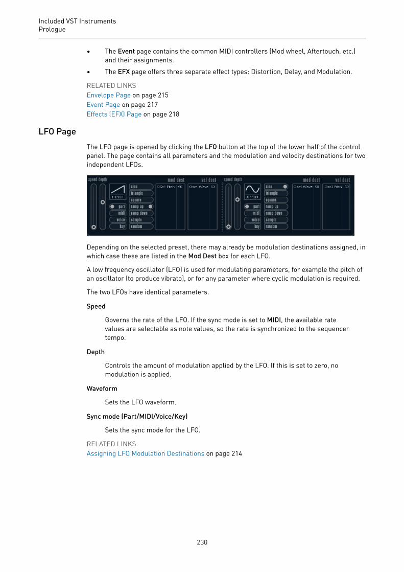
Included VST InstrumentsPrologue
• The Event page contains the common MIDI controllers (Mod wheel, Aftertouch, etc.)and their assignments.
• The EFX page offers three separate effect types: Distortion, Delay, and Modulation.
RELATED LINKSEnvelope Page on page 215Event Page on page 217Effects (EFX) Page on page 218
LFO PageThe LFO page is opened by clicking the LFO button at the top of the lower half of the controlpanel. The page contains all parameters and the modulation and velocity destinations for twoindependent LFOs.
Depending on the selected preset, there may already be modulation destinations assigned, inwhich case these are listed in the Mod Dest box for each LFO.
A low frequency oscillator (LFO) is used for modulating parameters, for example the pitch ofan oscillator (to produce vibrato), or for any parameter where cyclic modulation is required.
The two LFOs have identical parameters.
Speed
Governs the rate of the LFO. If the sync mode is set to MIDI, the available ratevalues are selectable as note values, so the rate is synchronized to the sequencertempo.
Depth
Controls the amount of modulation applied by the LFO. If this is set to zero, nomodulation is applied.
Waveform
Sets the LFO waveform.
Sync mode (Part/MIDI/Voice/Key)
Sets the sync mode for the LFO.
RELATED LINKSAssigning LFO Modulation Destinations on page 214
230
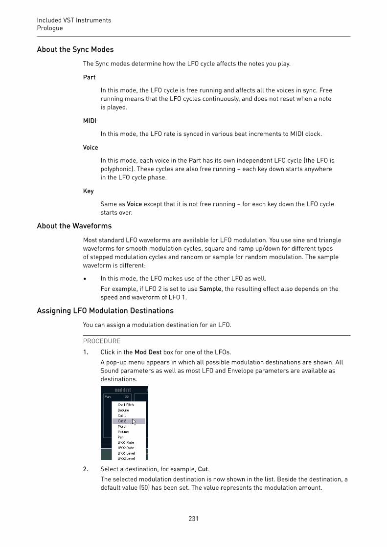
Included VST InstrumentsPrologue
About the Sync ModesThe Sync modes determine how the LFO cycle affects the notes you play.
Part
In this mode, the LFO cycle is free running and affects all the voices in sync. Freerunning means that the LFO cycles continuously, and does not reset when a noteis played.
MIDI
In this mode, the LFO rate is synced in various beat increments to MIDI clock.
Voice
In this mode, each voice in the Part has its own independent LFO cycle (the LFO ispolyphonic). These cycles are also free running – each key down starts anywherein the LFO cycle phase.
Key
Same as Voice except that it is not free running – for each key down the LFO cyclestarts over.
About the WaveformsMost standard LFO waveforms are available for LFO modulation. You use sine and trianglewaveforms for smooth modulation cycles, square and ramp up/down for different typesof stepped modulation cycles and random or sample for random modulation. The samplewaveform is different:
• In this mode, the LFO makes use of the other LFO as well.For example, if LFO 2 is set to use Sample, the resulting effect also depends on thespeed and waveform of LFO 1.
Assigning LFO Modulation DestinationsYou can assign a modulation destination for an LFO.
PROCEDURE1. Click in the Mod Dest box for one of the LFOs.
A pop-up menu appears in which all possible modulation destinations are shown. AllSound parameters as well as most LFO and Envelope parameters are available asdestinations.
2. Select a destination, for example, Cut.The selected modulation destination is now shown in the list. Beside the destination, adefault value (50) has been set. The value represents the modulation amount.
231

Included VST InstrumentsPrologue
• You can set positive and negative modulation values by clicking on the value inthe list, typing in a new value, and pressing Enter.
To enter negative values, type a minus sign followed by the value.
3. Select a suitable LFO Waveform, Speed, Depth, and Sync mode.You should now hear the Cut parameter being modulated by the LFO.
4. Using the same basic method, you can add any number of modulation destinations forthe LFO.They are all listed in the Mod Dest box.
• To remove a modulation destination, click on its name in the list and select Offfrom the pop-up menu.
Assigning LFO Velocity DestinationsYou can also assign velocity-controlled LFO modulation.
PROCEDURE1. Click in the Vel Dest box for one of the LFOs.
A pop-up menu appears in which all possible velocity destinations are shown.
2. Select a destination.The selected velocity destination is now shown in the list. Beside the destination, adefault value (50) has been set. The value represents the modulation amount.
• You can set positive and negative values by clicking on the value in the list, typingin a new value, and pressing Enter.
To enter negative values, type a minus sign followed by the value.
3. Using the same basic method, you can add any number of velocity destinations for theLFO.They are all listed in the Vel Dest box.
• To remove a velocity destination, click on its name in the list and select Off fromthe pop-up menu.
LFO modulation velocity controlIf you follow the steps above and select the Cut parameter as a Velocity destination, thefollowing happens:
• The harder you strike the key, the more the Cut parameter is modulated by the LFO.• If you enter a negative value for the velocity modulation amount, the opposite happens:
the harder you play, the less the Cut parameter is modulated by the LFO.
Envelope PageThe Envelope page is opened by clicking the ENV button at the top of the lower half of thecontrol panel. The page contains all parameters and the modulation and velocity destinationsfor the four independent envelope generators.
Envelope generators govern how a parameter value changes when a key is pressed, when akey is held and finally when a key is released.
232
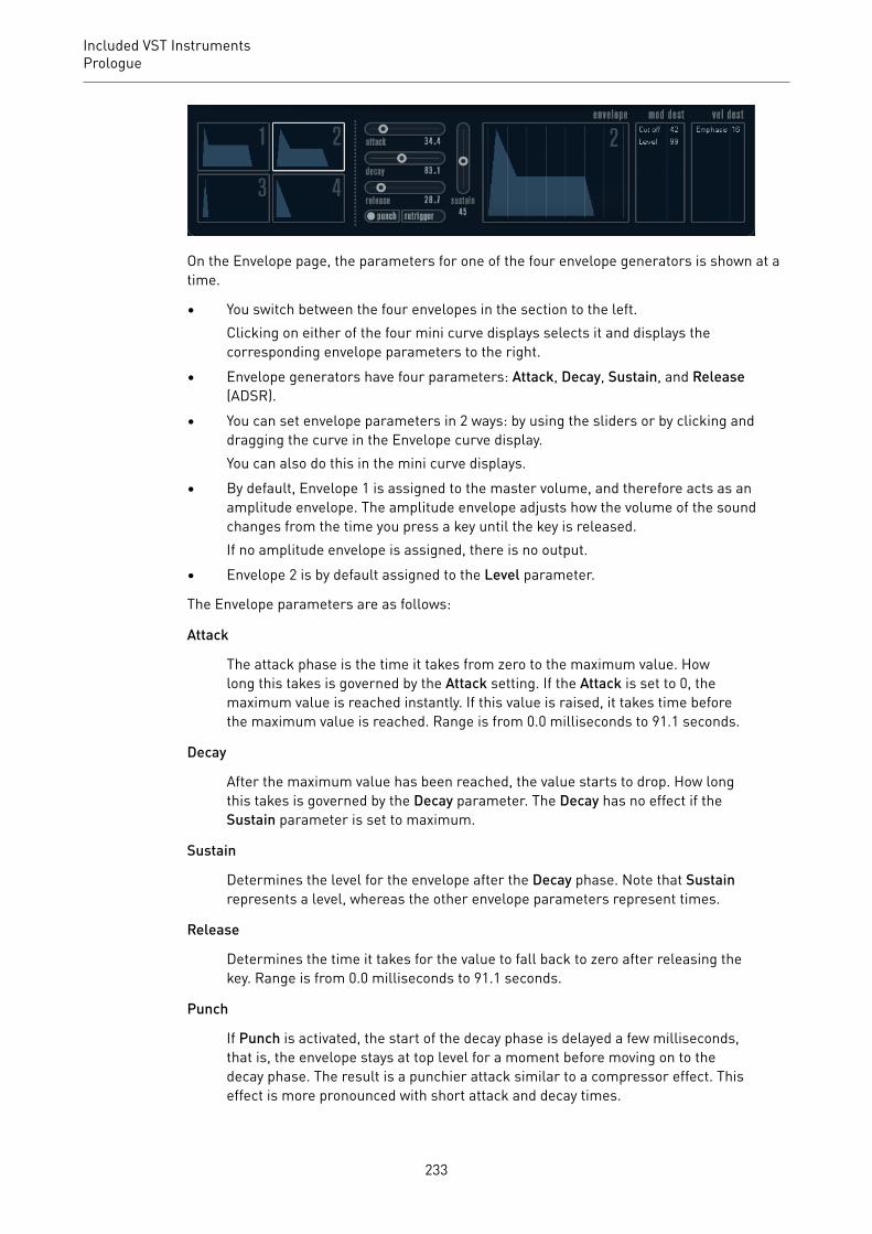
Included VST InstrumentsPrologue
On the Envelope page, the parameters for one of the four envelope generators is shown at atime.
• You switch between the four envelopes in the section to the left.Clicking on either of the four mini curve displays selects it and displays thecorresponding envelope parameters to the right.
• Envelope generators have four parameters: Attack, Decay, Sustain, and Release(ADSR).
• You can set envelope parameters in 2 ways: by using the sliders or by clicking anddragging the curve in the Envelope curve display.You can also do this in the mini curve displays.
• By default, Envelope 1 is assigned to the master volume, and therefore acts as anamplitude envelope. The amplitude envelope adjusts how the volume of the soundchanges from the time you press a key until the key is released.If no amplitude envelope is assigned, there is no output.
• Envelope 2 is by default assigned to the Level parameter.
The Envelope parameters are as follows:
Attack
The attack phase is the time it takes from zero to the maximum value. Howlong this takes is governed by the Attack setting. If the Attack is set to 0, themaximum value is reached instantly. If this value is raised, it takes time beforethe maximum value is reached. Range is from 0.0 milliseconds to 91.1 seconds.
Decay
After the maximum value has been reached, the value starts to drop. How longthis takes is governed by the Decay parameter. The Decay has no effect if theSustain parameter is set to maximum.
Sustain
Determines the level for the envelope after the Decay phase. Note that Sustainrepresents a level, whereas the other envelope parameters represent times.
Release
Determines the time it takes for the value to fall back to zero after releasing thekey. Range is from 0.0 milliseconds to 91.1 seconds.
Punch
If Punch is activated, the start of the decay phase is delayed a few milliseconds,that is, the envelope stays at top level for a moment before moving on to thedecay phase. The result is a punchier attack similar to a compressor effect. Thiseffect is more pronounced with short attack and decay times.
233
Included VST InstrumentsPrologue
Retrigger
If Retrigger is activated, the envelope retriggers each time you play a new note.However, with certain textures/pad sounds and a limited number of voices, itis recommended to leave the button deactivated, due to click noises that mightoccur.
Assigning Envelope Modulation DestinationsYou can assign a modulation destination for an envelope.
PROCEDURE1. Click in the Mod Dest box for one of the envelopes.
A pop-up menu appears in which all possible modulation destinations are shown. AllSound parameters as well as most LFO and Envelope parameters are available asdestinations.
2. Select a destination, for example, Cut.The selected modulation destination is now shown in the list. Beside the destination, adefault value (50) has been set. The value represents the modulation amount.
• You can set positive and negative modulation values by clicking on the value inthe list, typing in a new value, and pressing Enter.To enter negative values, type a minus sign followed by the value.
3. Select a suitable envelope curve for the modulation.You should now hear the Cut parameter being modulated by the envelope as you play.
4. Using the same basic method, you can add any number of modulation destinations forthe envelope.They are all listed in the Mod Dest box.
• To remove a modulation destination, click on its name in the list and select Offfrom the pop-up menu.
Assigning Envelope Velocity DestinationsYou can also assign velocity-controlled envelope modulation, that is, the modulation isgoverned by how hard or soft you strike a key.
PROCEDURE1. Click in the Vel Dest box for one of the envelopes.
A pop-up menu appears in which all possible velocity destinations are shown.
2. Select a destination.The selected velocity destination is now shown in the list. Beside the destination, adefault value (50) has been set. The value represents the modulation amount. Seebelow for an example of how velocity modulation works.
• You can set positive and negative values by clicking on the value in the list, typingin a new value, and pressing Enter.To enter negative values, type a minus sign followed by the value.
3. Using the same basic method, you can add any number of velocity destinations for theEnvelope.They are all listed in the Vel Dest box.
234

Included VST InstrumentsPrologue
• To remove a velocity destination, click on its name in the list and select Off fromthe pop-up menu.
Envelope modulation velocity controlIf you follow the steps above and select the Cut parameter as a Velocity destination, thefollowing happens:
• The harder you strike the key, the more the parameter is modulated by the envelope.• If you enter a negative value for the velocity modulation amount, the opposite happens;
the harder you play the less the Cut parameter is modulated by the Envelope.
Event PageThe Event page is opened by clicking the EVENT button at the top of the lower half of thecontrol panel. This page contains the most common MIDI controllers and their assignments.
Modulation Wheel
The modulation wheel on your keyboard can be used to modulate parameters.
Velocity
Controls parameters according to how hard or soft you play notes on yourkeyboard. A common application of velocity is to make sounds brighter andlouder if you strike the key harder.
Aftertouch
Aftertouch, or channel pressure, is MIDI data sent when pressure is appliedto a keyboard after the key has been struck, and while it is being held down orsustained. Aftertouch is often routed to control filter cutoff, volume, and otherparameters to add expression.
Key Pitch Tracking
This can change parameter values linearly according to where on the keyboardyou play.
Assign a Controller to a Parameter
PROCEDURE1. Click in the Mod Dest box for one of the controllers.
A pop-up menu appears in which all possible modulation destinations are shown. AllSound parameters as well as most LFO and Envelope parameters are available asdestinations.
2. Select a destination.
235
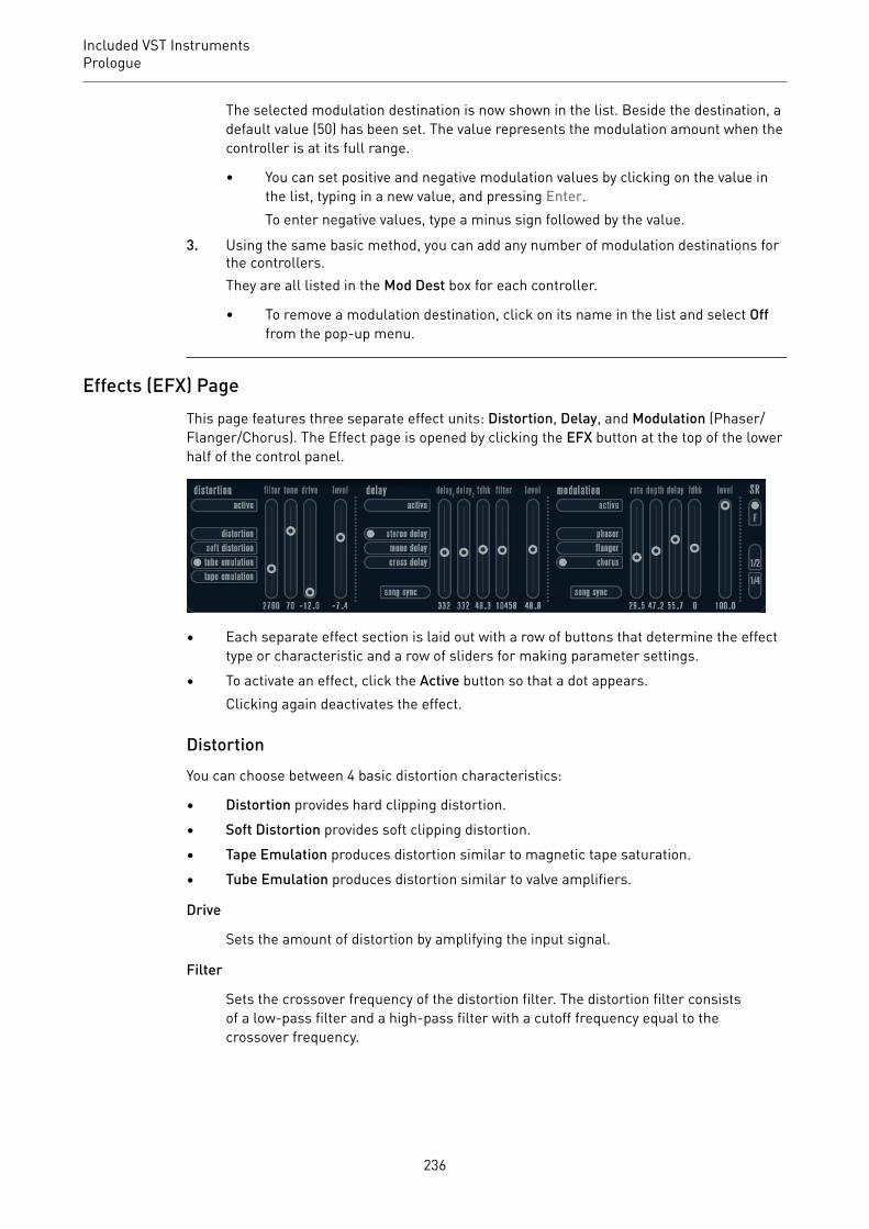
Included VST InstrumentsPrologue
The selected modulation destination is now shown in the list. Beside the destination, adefault value (50) has been set. The value represents the modulation amount when thecontroller is at its full range.
• You can set positive and negative modulation values by clicking on the value inthe list, typing in a new value, and pressing Enter.To enter negative values, type a minus sign followed by the value.
3. Using the same basic method, you can add any number of modulation destinations forthe controllers.They are all listed in the Mod Dest box for each controller.
• To remove a modulation destination, click on its name in the list and select Offfrom the pop-up menu.
Effects (EFX) PageThis page features three separate effect units: Distortion, Delay, and Modulation (Phaser/Flanger/Chorus). The Effect page is opened by clicking the EFX button at the top of the lowerhalf of the control panel.
• Each separate effect section is laid out with a row of buttons that determine the effecttype or characteristic and a row of sliders for making parameter settings.
• To activate an effect, click the Active button so that a dot appears.Clicking again deactivates the effect.
DistortionYou can choose between 4 basic distortion characteristics:
• Distortion provides hard clipping distortion.• Soft Distortion provides soft clipping distortion.• Tape Emulation produces distortion similar to magnetic tape saturation.• Tube Emulation produces distortion similar to valve amplifiers.
Drive
Sets the amount of distortion by amplifying the input signal.
Filter
Sets the crossover frequency of the distortion filter. The distortion filter consistsof a low-pass filter and a high-pass filter with a cutoff frequency equal to thecrossover frequency.
236

Included VST InstrumentsPrologue
Tone
Controls the relative amount of low-pass and high-pass filtered signal.
Level
Controls the output level of the effect.
DelayYou can choose between 3 basic delay characteristics:
• Stereo Delay has two separate delay lines panned left and right.• In Mono Delay, the two delay lines are connected in series for monophonic dual tap
delay effects.• In Cross Delay, the delayed sound bounces between the stereo channels.
Song Sync
Activates/Deactivates tempo sync of the delay times.
Delay 1
Sets the delay time ranging from 0 ms to 728 ms. If MIDI sync is activated, therange is from 1/32 to 1/1; straight, triplet or dotted.
Delay 2
Same as Delay 1.
Feedback
Controls the decay of the delays. With higher settings, the echoes repeat longer.
Filter
A low-pass filter is built into the feedback loop of the delay. This parametercontrols the cutoff frequency of this feedback filter. Low settings result insuccessive echoes sounding darker.
Level
Controls the output level of the effect.
ModulationYou can choose between 3 basic modulation characteristics:
• Phaser uses an 8-pole all-pass filter to produce the classic phasing effect.• Flanger is composed of two independent delay lines with feedback for the left and the
right channel. The delay time of both delays is modulated by one LFO with adjustablefrequency.
• Chorus produces a rich chorus effect with 4 delays modulated by four independentLFOs.
Song Sync
Activates/Deactivates tempo sync of the Rate parameter.
237

Included VST InstrumentsRetrologue
Rate
Sets the rate of the LFOs modulating the delay time. If Song Sync is activated, therate is synchronized to various beat increments.
Depth
Controls the depth of the delay time modulation.
Delay
Sets the delay time of the four delay lines.
Feedback
Controls the amount of positive or negative feedback for all four delay lines.
Level
Controls the output level of the effect.
SR ParametersWith these buttons, you can change the sample rate. Lower sample rates basically reducethe high frequency content and sound quality, but the pitch is not altered. This is useful toemulate the lo-fi sounds of older digital synths.
• If the F button is active, the program of the selected part plays back with the samplerate set in the host application.
• If the 1/2 button is active, the program of the selected part plays back with half theoriginal sample rate.
• If the 1/4 button is active, the program of the selected part plays back with a quarter ofthe original sample rate.
A bonus effect of using lower sample rates is that it reduces the load on the computer CPU,allowing for more simultaneous voices to be played, etc.
Retrologue
CubaseLE
CubaseAI
CubaseElements
CubaseArtist
CubasePro
Nuendo NEK
Included with – – – X X – X
This VST instrument is described in detail in the separate PDF document Retrologue.
Spector
CubaseLE
CubaseAI
CubaseElements
CubaseArtist
CubasePro
Nuendo NEK
Included with – – – X X – X
238
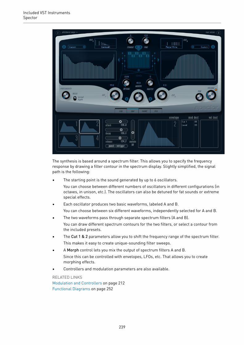
Included VST InstrumentsSpector
The synthesis is based around a spectrum filter. This allows you to specify the frequencyresponse by drawing a filter contour in the spectrum display. Slightly simplified, the signalpath is the following:
• The starting point is the sound generated by up to 6 oscillators.You can choose between different numbers of oscillators in different configurations (inoctaves, in unison, etc.). The oscillators can also be detuned for fat sounds or extremespecial effects.
• Each oscillator produces two basic waveforms, labeled A and B.You can choose between six different waveforms, independently selected for A and B.
• The two waveforms pass through separate spectrum filters (A and B).You can draw different spectrum contours for the two filters, or select a contour fromthe included presets.
• The Cut 1 & 2 parameters allow you to shift the frequency range of the spectrum filter.This makes it easy to create unique-sounding filter sweeps.
• A Morph control lets you mix the output of spectrum filters A and B.Since this can be controlled with envelopes, LFOs, etc. That allows you to createmorphing effects.
• Controllers and modulation parameters are also available.
RELATED LINKSModulation and Controllers on page 212Functional Diagrams on page 252
239
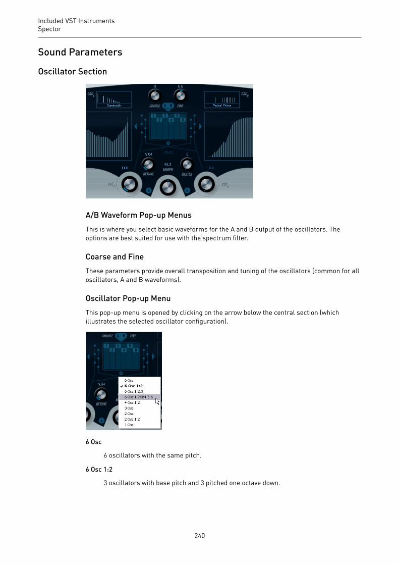
Included VST InstrumentsSpector
Sound Parameters
Oscillator Section
A/B Waveform Pop-up MenusThis is where you select basic waveforms for the A and B output of the oscillators. Theoptions are best suited for use with the spectrum filter.
Coarse and FineThese parameters provide overall transposition and tuning of the oscillators (common for alloscillators, A and B waveforms).
Oscillator Pop-up MenuThis pop-up menu is opened by clicking on the arrow below the central section (whichillustrates the selected oscillator configuration).
6 Osc
6 oscillators with the same pitch.
6 Osc 1:2
3 oscillators with base pitch and 3 pitched one octave down.
240

Included VST InstrumentsSpector
6 Osc 1:2:3
Three groups of two oscillators with the pitch ratio 1:2:3 (2 oscillators with basepitch, 2 oscillators at half the frequency of the base pitch, and 2 oscillators at athird of the frequency).
6 Osc 1:2:3:4:5:6
6 oscillators tuned with the pitch ratio 1:2:3:4:5:6 (known as the subharmonicseries).
4 Osc 1:2
2 oscillators with base pitch and 2 pitched one octave down.
3 Osc
3 oscillators with the same pitch.
2 Osc
2 oscillators with the same pitch.
2 Osc 1:2
One oscillator with base pitch and one pitched one octave down.
1 Osc
A single oscillator. In this mode, the Detune and Cut II parameters are not active.
DetuneDetunes the oscillators. Low values give gentle chorus-like detuning. Raising the controldetunes the oscillators by several semitones for special effects.
RasterReduces the number of harmonics present in the oscillator waveforms in the followingmanner:
• If 0 is selected, all harmonics are present.• If 1 is selected, only every second harmonic is present.• If 2 is selected, only every third harmonic is present.
And so on.
PortamentoThis parameter makes the pitch glide between the notes you play. The parameter settingdetermines the time it takes for the pitch to glide from one note to the next. Turn the knobclockwise for longer glide time.
The Mode switch allows you to apply glide only if you play a legato note. Legato mode onlyworks with monophonic parts.
241

Included VST InstrumentsSpector
Spectrum Filter Sections
This is where you create the contours, that is, frequency response characteristics, for the two128 pole resonant spectrum filters A and B.
• You can use the Preset pop-up menu to select a preset contour.• To change the contour, click and draw with the mouse.• If you want to calculate a random spectrum filter curve, select Randomize from the
Preset pop-up menu.Each time you choose this function, a new randomized spectrum is calculated.
Cut I and II
These parameters work like cutoff frequency controls on a conventional filter: With the Cutcontrols at the maximum setting, the full frequency range is used for the spectrum filter.Lowering the Cut controls gradually moves the entire contour down in frequency, closing thefilter.
NOTE
• If a 2 oscillator configuration is used, you can set different cutoffs for the twooscillators. If more than two oscillators are used, they are internally divided into twogroups, for which you can set independent cutoffs with Cut I and Cut II.
• If the Spectrum Sync button (link symbol) between the cut controls is activated, thetwo knobs are linked and follow each other and are set to the same value.
MorphControls the mix between the sound of spectrum filters A and B. If the Morph knob is turnedfully left, only the A sound is heard. If it is turned right only the B sound is heard. This allowsyou to seamlessly morph between two totally different sounds.
Master Volume and Pan
242

Included VST InstrumentsSpector
The master Volume knob controls the master volume (amplitude) of the instrument. Bydefault, this parameter is controlled by Envelope 1, to generate an amplitude envelope forthe oscillators.
The Pan knob controls the position of the instrument in the stereo spectrum. You can usePan as a modulation destination.
Modulation and ControllersThe lower half of the control panel displays the various modulation and controllerassignment pages available, as well as the EFX page. You switch between these pages usingthe buttons above this section.
The following pages are available:
• The LFO page has two low frequency oscillators (LFOs) for modulating parameters.• The ENV page contains the four envelope generators that can be assigned to control
parameters.• The Event page contains the common MIDI controllers (Mod wheel, Aftertouch, etc.)
and their assignments.• The EFX page offers three separate effect types: Distortion, Delay, and Modulation.
RELATED LINKSEnvelope Page on page 215Event Page on page 217Effects (EFX) Page on page 218
LFO PageThe LFO page is opened by clicking the LFO button at the top of the lower half of the controlpanel. The page contains all parameters and the modulation and velocity destinations for twoindependent LFOs.
Depending on the selected preset, there may already be modulation destinations assigned, inwhich case these are listed in the Mod Dest box for each LFO.
A low frequency oscillator (LFO) is used for modulating parameters, for example the pitch ofan oscillator (to produce vibrato), or for any parameter where cyclic modulation is required.
The two LFOs have identical parameters.
Speed
Governs the rate of the LFO. If the sync mode is set to MIDI, the available ratevalues are selectable as note values, so the rate is synchronized to the sequencertempo.
243

Included VST InstrumentsSpector
Depth
Controls the amount of modulation applied by the LFO. If this is set to zero, nomodulation is applied.
Waveform
Sets the LFO waveform.
Sync mode (Part/MIDI/Voice/Key)
Sets the sync mode for the LFO.
RELATED LINKSAssigning LFO Modulation Destinations on page 214
About the Sync ModesThe Sync modes determine how the LFO cycle affects the notes you play.
Part
In this mode, the LFO cycle is free running and affects all the voices in sync. Freerunning means that the LFO cycles continuously, and does not reset when a noteis played.
MIDI
In this mode, the LFO rate is synced in various beat increments to MIDI clock.
Voice
In this mode, each voice in the Part has its own independent LFO cycle (the LFO ispolyphonic). These cycles are also free running – each key down starts anywherein the LFO cycle phase.
Key
Same as Voice except that it is not free running – for each key down the LFO cyclestarts over.
About the WaveformsMost standard LFO waveforms are available for LFO modulation. You use sine and trianglewaveforms for smooth modulation cycles, square and ramp up/down for different typesof stepped modulation cycles and random or sample for random modulation. The samplewaveform is different:
• In this mode, the LFO makes use of the other LFO as well.For example, if LFO 2 is set to use Sample, the resulting effect also depends on thespeed and waveform of LFO 1.
Assigning LFO Modulation DestinationsYou can assign a modulation destination for an LFO.
PROCEDURE1. Click in the Mod Dest box for one of the LFOs.
244
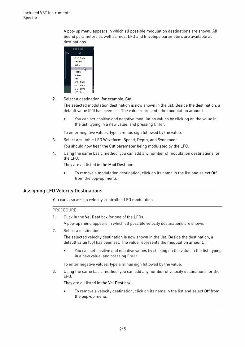
Included VST InstrumentsSpector
A pop-up menu appears in which all possible modulation destinations are shown. AllSound parameters as well as most LFO and Envelope parameters are available asdestinations.
2. Select a destination, for example, Cut.The selected modulation destination is now shown in the list. Beside the destination, adefault value (50) has been set. The value represents the modulation amount.
• You can set positive and negative modulation values by clicking on the value inthe list, typing in a new value, and pressing Enter.
To enter negative values, type a minus sign followed by the value.
3. Select a suitable LFO Waveform, Speed, Depth, and Sync mode.You should now hear the Cut parameter being modulated by the LFO.
4. Using the same basic method, you can add any number of modulation destinations forthe LFO.They are all listed in the Mod Dest box.
• To remove a modulation destination, click on its name in the list and select Offfrom the pop-up menu.
Assigning LFO Velocity DestinationsYou can also assign velocity-controlled LFO modulation.
PROCEDURE1. Click in the Vel Dest box for one of the LFOs.
A pop-up menu appears in which all possible velocity destinations are shown.
2. Select a destination.The selected velocity destination is now shown in the list. Beside the destination, adefault value (50) has been set. The value represents the modulation amount.
• You can set positive and negative values by clicking on the value in the list, typingin a new value, and pressing Enter.
To enter negative values, type a minus sign followed by the value.
3. Using the same basic method, you can add any number of velocity destinations for theLFO.They are all listed in the Vel Dest box.
• To remove a velocity destination, click on its name in the list and select Off fromthe pop-up menu.
245
Included VST InstrumentsSpector
LFO modulation velocity controlIf you follow the steps above and select the Cut parameter as a Velocity destination, thefollowing happens:
• The harder you strike the key, the more the Cut parameter is modulated by the LFO.• If you enter a negative value for the velocity modulation amount, the opposite happens:
the harder you play, the less the Cut parameter is modulated by the LFO.
Envelope PageThe Envelope page is opened by clicking the ENV button at the top of the lower half of thecontrol panel. The page contains all parameters and the modulation and velocity destinationsfor the four independent envelope generators.
Envelope generators govern how a parameter value changes when a key is pressed, when akey is held and finally when a key is released.
On the Envelope page, the parameters for one of the four envelope generators is shown at atime.
• You switch between the four envelopes in the section to the left.Clicking on either of the four mini curve displays selects it and displays thecorresponding envelope parameters to the right.
• Envelope generators have four parameters: Attack, Decay, Sustain, and Release(ADSR).
• You can set envelope parameters in 2 ways: by using the sliders or by clicking anddragging the curve in the Envelope curve display.You can also do this in the mini curve displays.
• By default, Envelope 1 is assigned to the master volume, and therefore acts as anamplitude envelope. The amplitude envelope adjusts how the volume of the soundchanges from the time you press a key until the key is released.If no amplitude envelope is assigned, there is no output.
• Envelope 2 is by default assigned to the Level parameter.
The Envelope parameters are as follows:
Attack
The attack phase is the time it takes from zero to the maximum value. Howlong this takes is governed by the Attack setting. If the Attack is set to 0, themaximum value is reached instantly. If this value is raised, it takes time beforethe maximum value is reached. Range is from 0.0 milliseconds to 91.1 seconds.
246

Included VST InstrumentsSpector
Decay
After the maximum value has been reached, the value starts to drop. How longthis takes is governed by the Decay parameter. The Decay has no effect if theSustain parameter is set to maximum.
Sustain
Determines the level for the envelope after the Decay phase. Note that Sustainrepresents a level, whereas the other envelope parameters represent times.
Release
Determines the time it takes for the value to fall back to zero after releasing thekey. Range is from 0.0 milliseconds to 91.1 seconds.
Punch
If Punch is activated, the start of the decay phase is delayed a few milliseconds,that is, the envelope stays at top level for a moment before moving on to thedecay phase. The result is a punchier attack similar to a compressor effect. Thiseffect is more pronounced with short attack and decay times.
Retrigger
If Retrigger is activated, the envelope retriggers each time you play a new note.However, with certain textures/pad sounds and a limited number of voices, itis recommended to leave the button deactivated, due to click noises that mightoccur.
Assigning Envelope Modulation DestinationsYou can assign a modulation destination for an envelope.
PROCEDURE1. Click in the Mod Dest box for one of the envelopes.
A pop-up menu appears in which all possible modulation destinations are shown. AllSound parameters as well as most LFO and Envelope parameters are available asdestinations.
2. Select a destination, for example, Cut.The selected modulation destination is now shown in the list. Beside the destination, adefault value (50) has been set. The value represents the modulation amount.
• You can set positive and negative modulation values by clicking on the value inthe list, typing in a new value, and pressing Enter.To enter negative values, type a minus sign followed by the value.
3. Select a suitable envelope curve for the modulation.You should now hear the Cut parameter being modulated by the envelope as you play.
4. Using the same basic method, you can add any number of modulation destinations forthe envelope.They are all listed in the Mod Dest box.
• To remove a modulation destination, click on its name in the list and select Offfrom the pop-up menu.
247
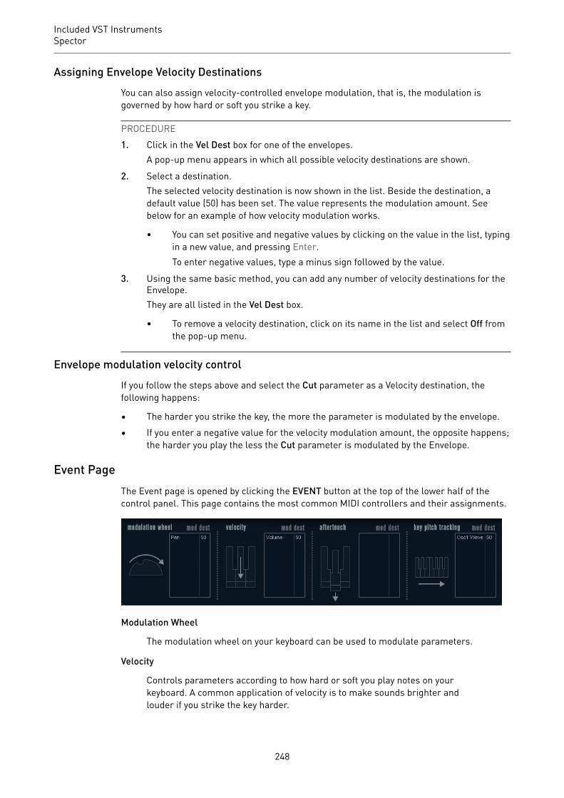
Included VST InstrumentsSpector
Assigning Envelope Velocity DestinationsYou can also assign velocity-controlled envelope modulation, that is, the modulation isgoverned by how hard or soft you strike a key.
PROCEDURE1. Click in the Vel Dest box for one of the envelopes.
A pop-up menu appears in which all possible velocity destinations are shown.
2. Select a destination.The selected velocity destination is now shown in the list. Beside the destination, adefault value (50) has been set. The value represents the modulation amount. Seebelow for an example of how velocity modulation works.
• You can set positive and negative values by clicking on the value in the list, typingin a new value, and pressing Enter.To enter negative values, type a minus sign followed by the value.
3. Using the same basic method, you can add any number of velocity destinations for theEnvelope.They are all listed in the Vel Dest box.
• To remove a velocity destination, click on its name in the list and select Off fromthe pop-up menu.
Envelope modulation velocity controlIf you follow the steps above and select the Cut parameter as a Velocity destination, thefollowing happens:
• The harder you strike the key, the more the parameter is modulated by the envelope.• If you enter a negative value for the velocity modulation amount, the opposite happens;
the harder you play the less the Cut parameter is modulated by the Envelope.
Event PageThe Event page is opened by clicking the EVENT button at the top of the lower half of thecontrol panel. This page contains the most common MIDI controllers and their assignments.
Modulation Wheel
The modulation wheel on your keyboard can be used to modulate parameters.
Velocity
Controls parameters according to how hard or soft you play notes on yourkeyboard. A common application of velocity is to make sounds brighter andlouder if you strike the key harder.
248
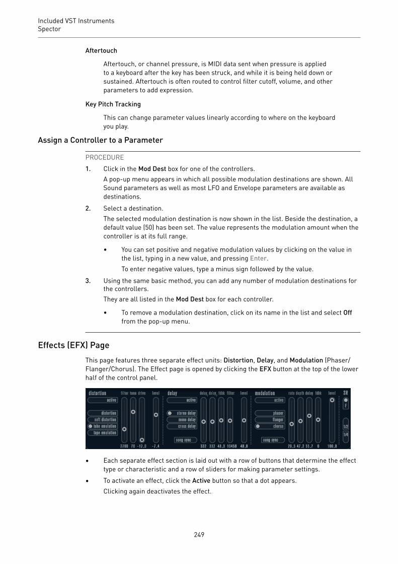
Included VST InstrumentsSpector
Aftertouch
Aftertouch, or channel pressure, is MIDI data sent when pressure is appliedto a keyboard after the key has been struck, and while it is being held down orsustained. Aftertouch is often routed to control filter cutoff, volume, and otherparameters to add expression.
Key Pitch Tracking
This can change parameter values linearly according to where on the keyboardyou play.
Assign a Controller to a Parameter
PROCEDURE1. Click in the Mod Dest box for one of the controllers.
A pop-up menu appears in which all possible modulation destinations are shown. AllSound parameters as well as most LFO and Envelope parameters are available asdestinations.
2. Select a destination.The selected modulation destination is now shown in the list. Beside the destination, adefault value (50) has been set. The value represents the modulation amount when thecontroller is at its full range.
• You can set positive and negative modulation values by clicking on the value inthe list, typing in a new value, and pressing Enter.To enter negative values, type a minus sign followed by the value.
3. Using the same basic method, you can add any number of modulation destinations forthe controllers.They are all listed in the Mod Dest box for each controller.
• To remove a modulation destination, click on its name in the list and select Offfrom the pop-up menu.
Effects (EFX) PageThis page features three separate effect units: Distortion, Delay, and Modulation (Phaser/Flanger/Chorus). The Effect page is opened by clicking the EFX button at the top of the lowerhalf of the control panel.
• Each separate effect section is laid out with a row of buttons that determine the effecttype or characteristic and a row of sliders for making parameter settings.
• To activate an effect, click the Active button so that a dot appears.Clicking again deactivates the effect.
249

Included VST InstrumentsSpector
DistortionYou can choose between 4 basic distortion characteristics:
• Distortion provides hard clipping distortion.• Soft Distortion provides soft clipping distortion.• Tape Emulation produces distortion similar to magnetic tape saturation.• Tube Emulation produces distortion similar to valve amplifiers.
Drive
Sets the amount of distortion by amplifying the input signal.
Filter
Sets the crossover frequency of the distortion filter. The distortion filter consistsof a low-pass filter and a high-pass filter with a cutoff frequency equal to thecrossover frequency.
Tone
Controls the relative amount of low-pass and high-pass filtered signal.
Level
Controls the output level of the effect.
DelayYou can choose between 3 basic delay characteristics:
• Stereo Delay has two separate delay lines panned left and right.• In Mono Delay, the two delay lines are connected in series for monophonic dual tap
delay effects.• In Cross Delay, the delayed sound bounces between the stereo channels.
Song Sync
Activates/Deactivates tempo sync of the delay times.
Delay 1
Sets the delay time ranging from 0 ms to 728 ms. If MIDI sync is activated, therange is from 1/32 to 1/1; straight, triplet or dotted.
Delay 2
Same as Delay 1.
Feedback
Controls the decay of the delays. With higher settings, the echoes repeat longer.
Filter
A low-pass filter is built into the feedback loop of the delay. This parametercontrols the cutoff frequency of this feedback filter. Low settings result insuccessive echoes sounding darker.
250

Included VST InstrumentsSpector
Level
Controls the output level of the effect.
ModulationYou can choose between 3 basic modulation characteristics:
• Phaser uses an 8-pole all-pass filter to produce the classic phasing effect.• Flanger is composed of two independent delay lines with feedback for the left and the
right channel. The delay time of both delays is modulated by one LFO with adjustablefrequency.
• Chorus produces a rich chorus effect with 4 delays modulated by four independentLFOs.
Song Sync
Activates/Deactivates tempo sync of the Rate parameter.
Rate
Sets the rate of the LFOs modulating the delay time. If Song Sync is activated, therate is synchronized to various beat increments.
Depth
Controls the depth of the delay time modulation.
Delay
Sets the delay time of the four delay lines.
Feedback
Controls the amount of positive or negative feedback for all four delay lines.
Level
Controls the output level of the effect.
SR ParametersWith these buttons, you can change the sample rate. Lower sample rates basically reducethe high frequency content and sound quality, but the pitch is not altered. This is useful toemulate the lo-fi sounds of older digital synths.
• If the F button is active, the program of the selected part plays back with the samplerate set in the host application.
• If the 1/2 button is active, the program of the selected part plays back with half theoriginal sample rate.
• If the 1/4 button is active, the program of the selected part plays back with a quarter ofthe original sample rate.
A bonus effect of using lower sample rates is that it reduces the load on the computer CPU,allowing for more simultaneous voices to be played, etc.
251

Included VST InstrumentsFunctional Diagrams
Functional Diagrams
Prologue Diagram
Mystic Diagram
252

Included VST InstrumentsFunctional Diagrams
Spector Diagram
253
Index
AAmp Simulation
AmpSimulator 10Quadrafuzz v2 16VST Amp Rack 20VST Bass Rack 27
AmpSimulator 10Anymix Pro 124Arpache 5 157Arpache SX 159Auto LFO 162AutoPan 82
BBass Manager 137Beat Designer 163BitCrusher 11Brickwall Limiter 36
CChopper Effects
AutoPan 82Chopper 84
Chorder 170Chorus Effects
Chorus 85StudioChorus 95
Cloner 86Compressors
Compressor 38Compressor (MIDI) 175DeEsser 39Maximizer 48MultibandCompressor 51Tube Compressor 58Vintage Compressor 59VSTDynamics 61
Context Gate 175CurveEQ 64
DDaTube 12DeEsser 39Delays
Cloner 86ModMachine 4
MonoDelay 7PingPongDelay 8Quadrafuzz v2 16StereoDelay 9
Density 177Distortion 13Dithering
UV22HR 81DJ-EQ 64DualFilter 73
EEnvelope Shapers
EnvelopeShaper 42MultibandEnvelopeShaper 53
ExpandersExpander 43MultibandExpander 55
FFlanger 87Frequency 69
GGates
Gate 45Quadrafuzz v2 16VSTDynamics 61
GEQ-10 65GEQ-30 65Groove Agent SE 193Grungelizer 13
HHALion Sonic SE 193
LLimiters
Brickwall Limiter 36Limiter 47Maximizer 48VSTDynamics 61
LoopMash 193LoopMash FX 100
254

Index
MMagneto II 14MatrixDecoder 139MatrixEncoder 140Maximizer 48Metalizer 89Micro Tuner 182MIDI Control 178MIDI Echo 178MIDI Gate 49MIDI Modifiers 181MIDI Monitor 181Mix6to2 143Mix8to2 144MixConvert V6 145MixerDelay 147ModMachine 4MonoDelay 7MonoToStereo 135MorphFilter 73MultibandCompressor 51MultibandEnvelopeShaper 53MultibandExpander 55MultiScope 148Mystic 207
Functional Diagram 252
NNote to CC 183
OOctaver 103
PPadshop 221Phaser 90PingPongDelay 8Pitch Correct 103PitchDriver 106PostFilter 75Prologue 221
Functional Diagram 252
QQuadrafuzz v2 16Quantizer 183
RRetrologue 238REVelation 107REVerence 110RingModulator 91RoomWorks 120RoomWorks SE 123Rotary 93
SSaturation
DaTube 12Magneto II 14Quadrafuzz v2 16
SMPTEGenerator 152SoftClipper 20Spector 238
Functional Diagram 252StepDesigner 184StepFilter 77StereoDelay 9StereoEnhancer 136StudioChorus 95StudioEQ 67
TTestGenerator 154ToneBooster 79Track Control 188Tranceformer 97Transformer 191Tremolo 98Tube Compressor 58Tuner 155
UUV22HR 81
VVibrato 99Vintage Compressor 59VST Amp Rack 20VST Bass Amp 27VST Connect CUE Mix 102VST Connect SE 102VST MultiPanner 137VSTDynamics 61
WWahWah 79
255


