74
PMC Coordination Meeting Supplemental Meeting Information July 2020 Virtual

PMC Coordination Meeting
Supplemental Meeting Information
July 2020
Virtual

1
TABLE OF CONTENTS
PMC & CMC MEETING SCHEDULE ....................................................................................... 2
TECHNICAL WORKING AND TASK GROUPS ...................................................................... 4
SAE AMS - P-17 COMMITTEE .................................................................................................. 9
PMC HANDBOOK DEVELOPMENT PLAN ........................................................................... 10
PMC OUTLINE AND PROGRESS REPORT ........................................................................ 63
INFORMATION ACCESS ......................................................................................................... 65
IMPORTANT DATES ................................................................................................................. 67
CMH-17 PMC CHAIRS AND COORDINATORS ................................................................... 69

2
PMC & CMC MEETING SCHEDULE
July 2020
See Agendas posted in PMC/CMC Agenda Booklet
NOTE: Meetings links will be sent to all registered attendees for all meetings except PMC Private/Working Meetings.
PMC Public/Main Meeting
PMC Private/Working Meeting
CMC Public/Main Meeting
Joint Meetings
Tutorials
MONDAY TUESDAY WEDNESDAY THURSDAY FRIDAY
Europe (pm) EDT PDT 7/6/2020 7/7/2020 7/8/2020 7/9/2020 7/10/2020
3:00 9:00 6:00
3:30 9:30 6:30
4:00 10:00 7:00
4:30 10:30 7:30
5:00 11:00 8:00
5:30 11:30 8:30
6:00 12:00 9:00
6:30 12:30 9:30
7:00 1:00 10:00
7:30 1:30 10:30
8:00 2:00 11:00
8:30 2:30 11:30
9:00 3:00 12:00
9:30 3:30 12:30
10:00 4:00 13:00
MONDAY TUESDAY WEDNESDAY THURSDAY FRIDAY
Europe (pm) EDT PDT 7/13/2020 7/14/2020 7/15/2020 7/16/2020 7/17/2020
3:00 9:00 6:00
3:30 9:30 6:30
4:00 10:00 7:00
4:30 10:30 7:30
5:00 11:00 8:00
5:30 11:30 8:30
6:00 12:00 9:00
6:30 12:30 9:30
7:00 1:00 10:00
7:30 1:30 10:30
8:00 2:00 11:00
8:30 2:30 11:30
9:00 3:00 12:00
9:30 3:30 12:30
CrashworthinessCrashworthiness
working meeting
Testing Spacecraft
Certification Tutorial
Part 1
Certification Tutorial
Part 2
WEEK 1
WEEK 2
Damage Tolerance
working meeting
Damage Tolerance
Damage Tolerance
working meeting
PMC Forum - Rev H
Content
Guidelines Bolted
Joints
Guidelines Bonded
Joints
Statistics
PMC/CMC
Coordination
Engine Applications
(PMC/CMC)
PMC/CMC Forum
CMC Testing
Sandwich working
meeting
Sandwich
Safety Management
Debond/Delam
Data Review
Debond/Delam
working meeting
CMC Materials and
Processes
Guidelines
Supportability SOBR
working meeting
CMC Data Review
CMC Design and
Analysis
SupportabilityTesting working
meeting
Guidelines Design,
Building Block, Cert,
etc
Certification Tutorial
Part 3
M&P

3
NOTE: Meetings links will be sent to all registered attendees for all meetings except PMC Private/Working Meetings.
MONDAY TUESDAY WEDNESDAY THURSDAY FRIDAY
Europe (pm) EDT PDT 7/20/2020 7/21/2020 7/22/2020 7/23/2020 7/24/2020
3:00 9:00 6:00
3:30 9:30 6:30
4:00 10:00 7:00
4:30 10:30 7:30
5:00 11:00 8:00
5:30 11:30 8:30
6:00 12:00 9:00
6:30 12:30 9:30
7:00 1:00 10:00
7:30 1:30 10:30
8:00 2:00 11:00
8:30 2:30 11:30
9:00 3:00 12:00
9:30 3:30 12:30
MONDAY TUESDAY
Europe (pm) EDT PDT 7/27/2020 7/28/2020
3:00 9:00 6:00
3:30 9:30 6:30
4:00 10:00 7:00
4:30 10:30 7:30
5:00 11:00 8:00
5:30 11:30 8:30
6:00 12:00 9:00
6:30 12:30 9:30
7:00 1:00 10:00
7:30 1:30 10:30
8:00 2:00 11:00
8:30 2:30 11:30
9:00 3:00 12:00
9:30 3:30 12:30
WEEK 3
WEEK 4
Statistics Tutorial
Part 1
Statistics Tutorial
Part 2
Spacecraft working
meeting
Core Task Group
working meeting
M&P working
meeting (Bonding
Process)
Spacecraft working
meeting
Coordination Executive
M&P working
meeting

4
POLYMER MATRIX COMPOSITES COMPOSITE MATERIALS HANDBOOK 17
TECHNICAL WORKING AND TASK GROUPS BONDED JOINT TASK GROUP (under Guidelines)
Mr. Rick Cole, NRC Aerospace Dr. Carl Q. Rousseau, Lockheed Martin Aeronautics
BONDING PROCESSES TASK GROUP (under Materials & Processes) Mr. Howard Creel, 3M CERTIFICATION TASK GROUP (under Guidelines)
Dr. Simon Waite, European Aviation Safety Agency (EASA) Ms. Cindy Ashforth, FAA/ANM A new CMH-17 Chapter to present certification guidance and identify issues of concern when using composite materials and showing compliance with Design, Production, and Continued Airworthiness Requirements. This recognizes the integrated link between all activities in accordance with Safety Management principles. COMPOSITES FOR SPACE WORKING GROUP Mr. Jeffrey D. Eichinger, Boeing Mr. Jeremy Jacobs, NASA Johnson Space Center The Spacecraft WG addresses the special concerns related to the application of polymer matrix composites in a space environment, including the introduction of additional physical property measurements into the handbook. In addition, the group will encourage the inclusion of material property data of interest to the spacecraft community. SPECIFICALLY:
To develop guidance on the qualification and usage of polymer matrix composites for spacecraft applications.
To differentiate development methodologies employed for spacecraft vs aircraft certification.
To influence spacecraft certification authorities to mature technical requirements To share “lessons learned” unique to spacecraft development challenges.

5
CORE TASK GROUP (under Sandwich) Dr. Susan Daggett, Absolute Value, LLC. Mr. Shannon Jones, Bell Helicopter Textron CRASHWORTHINESS WORKING GROUP
Mr. Allan Abramowitz Dr. Mostafa Rassaian
The newly formed Working Group will provide the support for the development of a new, self-contained section of the handbook on composite Crashworthiness and Energy Management for vehicle safety certification. The Work Group will also attempt to address the needs of the composites and aeronautics community at large, and to provide a unique forum of discussion for those working in industry, research institutions, and government agencies. Through a close interaction with ASTM Committee D-30, the Work Group will try to develop standards for the characterization of the energy-absorbing characteristics of composite material systems, such as the axial crushing of column-like members and of thin-wall tubular structures, representative of aircraft sub-floors and automotive-sized rails. In general, it will try to present, for the first time in a concise and comprehensive fashion, some recommended design guidelines and practices for the experimental and numerical characterization of the crash resistance of advanced composite structures. DAMAGE TOLERANCE TASK GROUP (under Safety Management)
Dr. Douglas S. Cairns, Montana State University Mr. Patrick Enjuto, Boeing Mr. Allen Fawcett Mr. Mike Smeets, Fokker Landing Gear Dr. Simon Waite, European Aviation Safety Agency (EASA)
DATA REVIEW WORKING GROUP Mr. Curtis R. Davies, Federal Aviation Administration - Materials and Structures
Dr. John S. Tomblin, Wichita State University, National Institute for Aviation Research
Establishes data documentation requirements, develops formats for data presentation, and provides the final technical and editorial review of all data prior to inclusion in the Handbook. Data Review Working Group (DRWG) performs data review according to a set of published procedures that have been developed by the working group To facilitate the data review process, the DRWG has established an electronic voting protocol that allows data reviews between CMH-17 formal meetings. DRWG works closely with

6
NCAMP in order that the data generated by that organization meets the requirements of CMH-17. Future tasks will address data requirements and formats for data presentation for adhesives. DISBOND AND DELAMINATION TASK GROUP (under Safety Management) Dr. Ronald Krueger, NIA/NASA LaRc Ms. Lisa McHugh, Northrop Grumman The Disbonding and Delamination is a Task Group under Safety Management. The group will determine an overall strategy for the handbook to address disbonding and delamination. The task group will examine methodologies needed to assure through-thickness integrity of bonds and laminations in polymer matrix composites. The group will review the existing document to assure that the sections related to delamination and disbonding are up-to-date. The group will inherit maintenance responsibility for sections on bonded joints written by the Joints WG. Appropriate interfaces will be made with existing groups to address identified gaps, in particular a strong interface will be created with the Damage Tolerance Task Group. The creation of new sections may be recommended if the current outline does not meet the needs of the strategic approach. GUIDELINES WORKING GROUP Dr. Carl Q. Rousseau, Lockheed Martin Aeronautics Mr. Stephen H. Ward, Collins Aerospace Develops and documents generic guidance information and data which is essential for the adequate design, certification or qualification, and production of composite parts and assemblies. The Guidelines Working Group also provides leadership and recommendations regarding the scope, responsibilities, and future direction of the Handbook. The current focus is on characterization test procedures and philosophy, materials property data, statistical analysis requirements, general design and analysis methodology, design data usage and quality assurance practices.

7
MATERIALS & PROCESS WORKING GROUP Dr. Margaret E. Roylance, Nano Tech Labs Mr. Daniel R. Ruffner Provides guidelines, descriptions and case studies of material types and processing options for the characterization and fabrication of polymer matrix composite materials. Current efforts are focused on revising Volume 3, Chapter 5 (Materials & Processes), preparing a new section in Volume 1, Chapter 5, which addresses test planning, and establishing guidelines for qualification of composite materials. SAFETY MANAGEMENT WORKING GROUP Dr. Larry Ilcewicz, FAA Aircraft Certification Service, Policy & Innovation Division
Ms. Cindy Ashforth, FAA Aircraft Certification Service, Policy & Innovation Division
The objective of the Safety Management Working Group is to provide the basis for assessing and managing risk by various means to assure and improve aircraft safety. The group is leading the development of the chapter in Volume 3 - Chapter 17 "Structural Safety Management". Chapter 17 includes considerations, analysis procedures and practical applications of safety management. In addition, the Safety Management Working Group is coordinating current initiatives involving the structural safety task group and efforts by the damage tolerance and disbond & delamination task groups. SANDWICH WORKING GROUP Mr. Lawrence A. Gintert, Independent Consultant Dr. Melanie Violette, Federal Aviation Administration Dr. Zhi Chen, The Aerospace Corporation The Sandwich Working Group is responsible for Volume 6, Structural Sandwich Composites. Volume 6 includes information on core, adhesive, and face sheet materials, and on testing, design, analysis, fabrication, quality control, and supportability of sandwich structure. Current efforts are focused on developing a long-term approach to data for core and adhesives, updating the volume with new information, and coordinating the content with other volumes of the Handbook.

8
STATISTICS WORKING GROUP
Dr. Elizabeth Clarkson, Wichita State University, National Institute for Aviation Research Mr. Curtis R. Davies, Federal Aviation Administration - Materials and Structures
Analyzes and/or develops statistical procedures for composite materials evaluation and quality control, and provides other statistical support to the Handbook as requested. Currently, the Statistics Working Group is addressing methodology for setting specification requirement values, and is also considering new, revised, and alternate methods of calculating material basis values. Statistics is working in close coordination with the Data Review Working Group relative to this latter subject. SUPPORTABILITY WORKING GROUP
Dr. Joseph Rakow, Exponent Failure Analysis Associates Mr. Stephen Starnes, US Navy
The objective of the Supportability Working Group is to provide the guidelines needed for post-production support of composite structures including inspection, repair, design, facilities, maintenance and disposal. The group is leading the development of two chapters in Volume 3 - Chapter 13 "Defects, Damage and Inspection" and Chapter 14 "Supportability, Maintenance, and Repair" which are intended for inclusion in Revision G of the handbook. TESTING WORKING GROUP
Dr. Daniel Adams, University of Utah Mr. John Moylan, Element Materials Technology
Offers descriptive and guidance information relating to the usage of chemical, physical and mechanical test methods for polymer matrix composites and their constituents. Currently, sections on failure modes, matrix test methods, prepreg characterization, tensile testing, damage tolerance testing, multi-axial testing, strain measurement, glass transition temperature, void volume analysis, and density determination are being prepared or rewritten (Volume 1, Chapters 4, 5 and 6).

9
SAE AMS - P-17 COMMITTEE
SAE AMS P-17 POLYMER MATRIX COMPOSITES
Shannon Jones, Chair Margaret Roylance, Vice-Chair SAE AMS P-17, Polymer Matrix Composites, is a technical committee in SAE’s Aerospace Materials Systems Group with the responsibility to develop and maintain material specifications and other SAE technical reports for composite materials, including prepregs, reinforcing fibers and fabrics, matrix resins, adhesives, and core materials. The committee works in conjunction with related bodies such as the Composite Materials Handbook-17 (CMH-17), ASTM Committee D30 on Composite Materials, the National Center for Advanced Materials Performance (NCAMP), the Performance Review Institute (PRI), and regulatory authorities such as FAA and EASA. The objectives of AMS P-17 are to: • Develop Aerospace Material Specifications (AMS) for the procurement of polymer matrix composites, sandwich construction, bonded structures, and associated materials used in structural applications. When applicable, ensure the material specification is tied to the CMH-17 Database. • Document best practices for processing and fabrication of end products from polymer matrix composites, sandwich construction, and bonded structures. • Provide a forum for the exchange of technical information related to polymer matrix composites. • Further the adaptation of industry sponsored material specifications through coordination with CMH-17, PRI, NCAMP, and associated organizations. • Coordinate with CMH-17 Materials and Processing Working Group in the preparation of material specifications for all new materials to be included in the CMH-17 Handbook. • Establish a system to ensure material specifications are controlled. Coordinate with PRI P-17 Qualified Products Group (QPG) to ensure the maintenance of Qualified Products Lists for appropriate specifications.

10
PMC HANDBOOK DEVELOPMENT PLAN
Working Groups
C Crashworthiness M Materials & Processes SD Specialized Data
D Data Review P Spacecraft SM Safety Mgmt
DD Disbond/Delam R Supportability SW Sandwich
DT Damage Tol. S Statistics T Testing
G Guidelines
Coding for this column Coding for this
column
White - open item In YP ballot
Approved YP item Planned for next YP
ballot
Closed item
Volume Chapter
Working Group
Responsibility
AI CH
Year Assign
ed Planned Revisions for Vol 1 - 3 Rev H / Vol 6 Rev A
Actual / Planned YP for Next Rev
EXEC 02-15
0 2002 Develop the CMH-17 SOP
Secretariat 05-12
0 2005 Propose a trial section with revision dates, post on exec forum
M&P + Guidelines + Stats
17-04
0 2017 Develop content for a shared database tutorial
EXEC 0 2020 Develop Post Rev H Handbook format, content, WGs, etc
VOLUME 1
CHAPTER 1 GENERAL INFORMATION
G Guidelines
1 2015 1.7.1.2 Laminae and laminates – revised SLC 3/2015

11
1 2015 1.8 Defintions – revised (applies to all PMC volumes) SLC 3/2015, SLC
3/2017 1 2018 1.8 Defintions – revised Fall 2018 1 Mar-19 1.8 Defintions – will reballot 4 definitions Spring 2019 1 Mar-19 Review Intro paragraphs before final publishing 1 Oct-19 Update Roadmaps
CHAPTER 2 GUIDELINES FOR PROPERTY TESTING OF COMPOSITES
G Guidelines
2 Complete chapter revision Fall 2018
2 Mar-19 Update to address comments from Fall 2018 YP ballot Spring 2019
P Spacecraft
2 Oct-19 Update to address comments from Spring 2019 YP ballot Fall 2019 YP 1
CHAPTER 3 EVALUATION OF REINFORCEMENT FIBERS
T Testing
3 Mar-19 Remove outdated sections Spring 2019
3 Mar-19 Needs review of "dated" material Fall 2019 YP 1
CHAPTER 4 MATRIX CHARACTERIZATION
T Testing
4 Mar-19 Update 4.1 to add adhesive characterization Spring 2019
4 Mar-19 Remove outdated sections Spring 2019 4 Mar-19 Needs review of "dated" material Summer 2020 YP1
4 Oct-19 Discussion of ASTM D14 test methods Identified ~ 16 adhesive characterization test methods to add.
Summer 2020 YP2
CHAPTER 5 PREPREG MATERIALS CHARACTERIZATION
T Testing
15-03
5 2015 Section 5.4 PREPREG PHYSICAL AND CHEMICAL PROPERTIES
Wichita 11/2017
5 Mar-19 Remove outdated sections Spring 2019

12
CHAPTER 6 LAMINA, LAMINATE, AND SPECIAL FORM CHARACTERIZATION
T Testing
15-03
6 2015 Section 6.6 THERMAL/PHYSICAL PROPERTY TESTS Wichita 11/2017
6 Mar-19 Update moisture conditioning sections Spring 2019
P Spacecraft
6 6.6 Thermal/Physical Property Tests
Fall 2019 YP 1
6 6.3.3 Accelerating conditioning times Fall 2019 YP 1
11-07
6 2011 Revise Volume 1 Section 6.8.5 Flexure testing Summer 2020 YP1
DD Disbond/Delam
11-08
6 2011 Revise Volume 1 Section 6.8.6 Mode III testing Summer 2020
DD Disbond/Delam
6 Mar-19 6.8.6, 6.9.4 Fracture mechanics sections need update Summer 2020
6 Mar-19 Tests to Develop Input Data for Composites Structural Simulation (ACP)
Summer 2020
6 Minor chapter cleanup Summer 2020 tbd
CHAPTER 7 STRUCTURAL ELEMENT CHARACTERIZATION
T Testing
7 Mar-19 Update moisture conditioning and bolted joint sections Spring 2019
DD Disbond/Delam
11-09
7 2011 Revise Volume 1 Section 7.4.2 and 7.4.3 Notched Laminate testing
Spring 2019
7 7.3.4 Structural Element Characterization (2 sub-sections) Fall 2019 YP 1
11-10
7 2011 Review/revise Volume 1 Chapter 7 bonded joint test methods Summer 2020 tbd
7 2020 Add bonding surface preparation test methods Summer 2020 tbd 7 Mar-19 7.8 High load rate testing of fastened joints (ACP Content) Summer 2020 tbd 7 Mar-19 7.8 ASTM Dynamic Impact Test (ACP) Summer 2020 tbd
7 Mar-19 7.8 High rate bonded joint testing – mode 1 (wedge), mode 2 (ENF) (ACP content)
Summer 2020 tbd
7 Minor chapter cleanup Summer 2020 tbd
CHAPTER 8 STATISTICAL METHODS
S Statistics
8 General linear statistical models - placement of this section will be in Vol 1 Ch8 per StatsWG meeting in SLC 3/2019
Fall 2018
8 Mar-19 8.3.7 regression analysis section revision Spring 2019

13
8 Mar-19 8.4.1 Equivalency section revision Spring 2019 8 Mar-19 8.4.1 Specification limits section Spring 2019 8 Mar-19 8.4.7 add General linear statistical models section (from Rev D) Spring 2019
VOLUME 2
CHAPTER 1 GENERAL INFORMATION
G Guidelines
1 2017 1.10 Data Reduction SLC 3/2017
D Data Review
09-10
1 2009 Set up requirements for adhesive data for future revision Rev J Item
CHAPTER 2 CARBON FIBER COMPOSITES
D Data Review
14-01
2 2014 Add fracture toughness data to CMH-17 Volume 2. Joint activity with Data Review and the Testing WGs as well as ASTM D30.06.
DDTG wants open for Rev J
2 2.2.1.11 T800SC 24k/3900-2C Unidirectional Tape Fall 2019 YP 1 2 2.2.2.11 T830HB 6k/3900-2D Plain Weave Fabric Fall 2019 YP 1 2 2.2.2.12 T700S 12k/2511 Plain Weave Fabric Fall 2019 YP 1
CHAPTER 3 BORON FIBER COMPOSITES
D Data Review
3
CHAPTER 4 GLASS FIBER COMPOSITES
D Data Review
4
CHAPTER 5 QUARTZ FIBER COMPOSITES
D Data Review
5
APPENDIX A1. CMH-17A DATA
D Data Review
6

14
VOLUME 3
CHAPTER 1 GENERAL INFORMATION
G Guidelines
1 Mar-19 Review Intro paragraphs before final publishing
CHAPTER 2 INTRODUCTION TO COMPOSITE STRUCTURE DEVELOPMENT
G Guidelines
2 No Revision
Planned for Rev H
CHAPTER 3 AIRCRAFT STRUCTURE CERTIFICATION AND COMPLIANCE
G Guidelines
09-08
3 2009 Update Volume 3, Chapter 3 to incorporate 20-107B changes and AMC 20-29
Summer 2020
CHAPTER 4 BUILDING
BLOCK APPROACH
FOR COMPOSITE
STRUCTURES
G Guidelines
4 4.6 Statistical methods for BB SLC 3/2017
4 Mar-19 4.1 - 4.3 revision (Enjuto, et al) Summer 2020
4 Mar-19 Analysis correlation vs design criteria, etc Modelling validation. Boeing input
Spring 2021
4 Mar-19 4.3.4 ACP input on robust analysis methods Verification and Validation
Summer 2020
4 4.4.2.3 Add historical military a/c BB programs Summer 2020 4 4.5 Add detailed BB plan vs program schedule Summer 2020
4 Mar-19 4.4.X Building Blocks for Analysis Supported by Test (Bombardier Case Study)
Spring 2021
CHAPTER 5 MATERIALS AND PROCESSES - THE EFFECT OF VARIABILITY
M Materials & Processes
5 2016 5.13 Generic Basis Values and Equivalencies St Paul 8/2016
5 2017 5.5.2.5 Long Discontinuous Fiber Reinforced Materials SLC 3/2017 5 2018 5.9.1.3 Cocuring Fall 2018

15
ON COMPOSITE PROPERTIES
S Statistics
09-14
5 2009 Additional verbiage in support of analyzing nested design - Rev H Summer 2020??
5 2013 5.4.2 Resin (add thermoplastics) Summer 2020
13-02
5 Jul-05 Prepare a new M&P content on Bonding:
5 2013 5.9.1.1 Adhesives Processing Summer 2020 5 2013 5.9.1.3 Cocuring Summer 2018
5 2013 5.9.1.4 Introduction/Philosophy of Bonding (Testing/Inspection/Quality)
Spring 2021
5 Jul-05 Thermoplastics "bonding"? Nothing specific for Rev H 5 5.9.5 Surface Preparation Fall 2019 YP 2
5 Mar-19 General discussion of AFP processes; description of closed-loop control (ACP content)
Summer 2020?
5 Mar-19 General discussion of process simulation; current capabilities and limitation (ACP content / Anoush P)
Summer 2020?
5 Mar-19 Discussion of elements of DFM, applications, validation examples (ACP content)
Summer 2020?
CHAPTER 6 QUALITY CONTROL OF PRODUCTION MATERIALS AND PROCESSES
M Materials & Processes
6 Mar-19 Surface preparation – process monitoring and automation; secondary bonding inspection (ACP content)
Summer 2020?
6 Mar-19 Surface preparation – process monitoring and automation; secondary bonding inspection (ACP content) - copy to Chapter 5
Summer 2020?
CHAPTER 7 DESIGN OF COMPOSITES
G Guidelines
7 2017 Chapter 7 section 7.4.4.2 changes Spring 2019
7 Mar-19 Guidelines for the current composite design process SMWG
7 Jun-20 Updated Outline for Sections 7.1, 7.2 and 7.6 (Including: A) Design Requirements, Criteria and Constraints, B) IPT, C) Technology Readiness Criteria and D) Design Cost Models)
Summer 2020
7 Jun-20 7.1 Update Spring 2021 7 Jun-20 7.2 Update Spring 2021 7 Jun-20 7.6 Update Spring 2021

16
CHAPTER 8 ANALYSIS OF LAMINATES
G Guidelines
8 Jul-18 8.2.5, add backing out E11 from multiple Exx data - Hendrix - from DRWG minutes Charleston meeting
Spring 2019
05-06
8 2005 Hybrid structure design and analysis close once v3ch7 reballot passes. No content for v3ch8.
8 8.2.5 Determining lamina moduli from laminate moduli test data Fall 2019 YP 1
DD Disbond/Delam
8 Mar-19 8.7.3.2 Delamination/disbonding arrest Summer 2020
DD Disbond/Delam
14-03
8 2014 8.7.5 Add a section on cohesive zone modeling for disbonding/delamination analysis.
Summer 2020
DD Disbond/Delam
14-04
8 2014 8.7.6 Add a chapter on disbonding/delamination arrest methods such as stitching, Z-pinning and rivets. Joint activity with DTWG
Summer 2020
DD Disbond/Delam
8.7.4 add CSDE fracture method for sandwich disbond usage Spring 2021
8 Mar-19 8.8 General progressive damage failure criteria (ACP content) Summer 2020 8 8.8.? Progressive damage modelling (Steve Russell) Summer 2020
C Crashworthiness
8 8.9 Dynamic progressive damage methods for impact modelling Spring 2021
CHAPTER 9 STRUCTURAL STABILITY ANALYSES
G Guidelines
9 Mar-19 Update chapter with non-normalized industry data, additional plate buckling eqns and refs
Spring 2019
9 Additional plate and stiffened panel buckling info (Enjuto/Mabson) Spring 2021
CHAPTER 10 DESIGN AND ANALYSIS OF BONDED JOINTS
G Guidelines
11-04
10 2011 Revise Volume 3 Chapter 10 Bonded Joints analysis NA
10 2014 Chapter 10 Bonded Joints Outline Miami 8/2014 10 2015 10.1 & 10.2 SLC 3/2015 10 2011 Full chapter to YPs Spring 2019 10 10.2 Design and Analysis of Bonded Joints - Introduction Fall 2019 YP 1

17
10 10.5.4 Bonded Joint Certification Issues – AIRCRAFT, Damage Tolerance
Fall 2019 YP 1
10 10.6 Bonded Joint Certification Issues / QUALIFICATION ISSUES – NON-AIRCRAFT
Fall 2019 YP 1
10 10.4.1 Metallic Adherend Bonded Joint Analysis Fall 2019 YP 2 10 10.5.2 Bonded Joint Certification Issues - Aircraft, Static Strength Fall 2019 YP 2 10 10.7 Derivation of Elastic-Perfectly-Plastic Shear Bondline Stress Fall 2019 YP 2 10 10.8 Bonded Joint Cert example (Fawcett, et al)
19-01
10 Mar-19 Future tutorial on Bonded Joints
CHAPTER 11 DESIGN AND ANALYSIS OF BOLTED JOINTS
G Guidelines
11-05
11 2011 Revise Volume 3 Chapter 11 Bolted Joints analysis NA
11 2011 95% content Summer 2020 11 2011 Full content Spring 2021
VOLUME 3
CHAPTER 12 DAMAGE RESISTANCE, DURABILITY, AND DAMAGE TOLERANCE
DT Damage Tol.
12 2015 12.3, Design Development and Substantiation - revision Wichita 10/2015
12 2013 12.4.6 Probability of detection - revision Wichita 12/2013 12 2014 12.5 Miami 8/2014 12 2017 12.6.2 Design issues and guidelines Wichita 11/2017
12 2015 12.6.4 Analysis Methods – revised SLC 3/2015
12 2017 12.7.4 Analysis Methods – Residual Strength Wichita 11/2017
12 2017 12.8.4 Thermal loads in a business jet horizontal stabilizer (designed by Fokker)
Wichita 11/2017
12 2017 12.8.5 General aviation (KC-100, KAI) Wichita 11/2017 12 2018 12.6 - Durability and Damage Growth under Cyclic Loading Fall 2018 12 2018 12.6.1 - Influencing factors Fall 2018 12 2018 12.6.2 - Design issues and guidelines Fall 2018 12 2018 12.6.3 - Test issues Fall 2018 12 2020 12.X? ARAC Extension Bonding Content Fall 2021 --- 12 Mar-19 12.2 Rules, requirements and compliance for aircraft ---
18
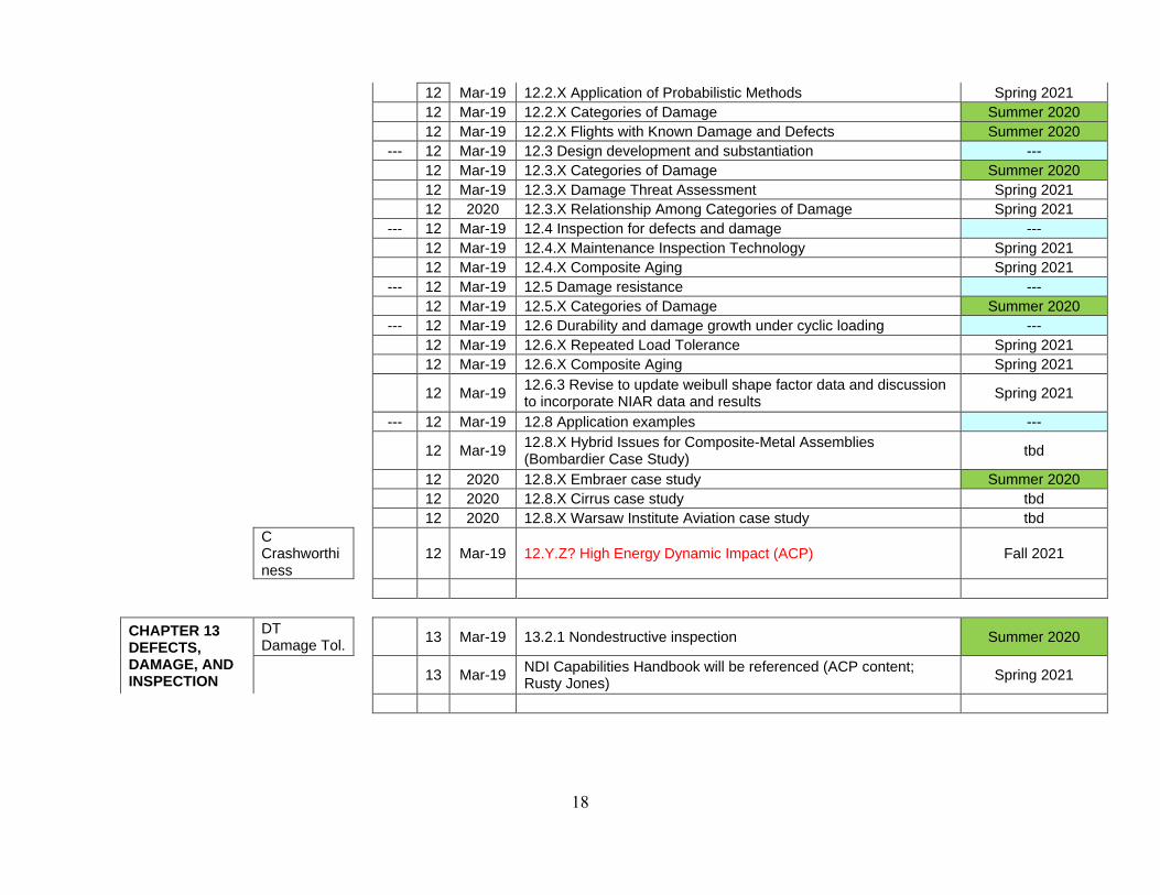
12 Mar-19 12.2.X Application of Probabilistic Methods Spring 2021 12 Mar-19 12.2.X Categories of Damage Summer 2020 12 Mar-19 12.2.X Flights with Known Damage and Defects Summer 2020 --- 12 Mar-19 12.3 Design development and substantiation --- 12 Mar-19 12.3.X Categories of Damage Summer 2020 12 Mar-19 12.3.X Damage Threat Assessment Spring 2021 12 2020 12.3.X Relationship Among Categories of Damage Spring 2021 --- 12 Mar-19 12.4 Inspection for defects and damage --- 12 Mar-19 12.4.X Maintenance Inspection Technology Spring 2021 12 Mar-19 12.4.X Composite Aging Spring 2021 --- 12 Mar-19 12.5 Damage resistance --- 12 Mar-19 12.5.X Categories of Damage Summer 2020 --- 12 Mar-19 12.6 Durability and damage growth under cyclic loading --- 12 Mar-19 12.6.X Repeated Load Tolerance Spring 2021 12 Mar-19 12.6.X Composite Aging Spring 2021
12 Mar-19 12.6.3 Revise to update weibull shape factor data and discussion to incorporate NIAR data and results
Spring 2021
--- 12 Mar-19 12.8 Application examples ---
12 Mar-19 12.8.X Hybrid Issues for Composite-Metal Assemblies (Bombardier Case Study)
tbd
12 2020 12.8.X Embraer case study Summer 2020 12 2020 12.8.X Cirrus case study tbd 12 2020 12.8.X Warsaw Institute Aviation case study tbd
C Crashworthiness
12 Mar-19 12.Y.Z? High Energy Dynamic Impact (ACP) Fall 2021
CHAPTER 13 DEFECTS, DAMAGE, AND INSPECTION
DT Damage Tol.
13 Mar-19 13.2.1 Nondestructive inspection Summer 2020
13 Mar-19 NDI Capabilities Handbook will be referenced (ACP content; Rusty Jones)
Spring 2021

19
CHAPTER 14 SUPPORTABILITY, MAINTENANCE, AND REPAIR
R Supportability
14 2016 complete chapter reorganization St. Paul (2016)
14 2016 14.1 – 14.5, 14.8, 14.9 updated St. Paul (2016)
14 2016 4.12 (Repair Case Studies) added, including introduction and 1st case study
St. Paul (2016)
14 2017 Initial work on Sec 14.6 (Composite & Metalbond Structure Repair)
SLC (2017)
14 2017 Parts of 14.6.2 Prerequisites for Repair SLC (2017)
14 2017 14.6.3 Repair Design and Processing + 14.6.4 Repair Quality Assurance (with CACRC refs)
SLC (2017)
14 2017 Most remaining parts of 14.6.2 Prerequisites for Repair Wichita (2017) 14 2018 14.6.2.7 - Contact and non-contact materials Fall 2018 14 2018 14.6.3.2.3.4 - Example of a bolted repair Fall 2018 14 2018 new outline for Section 14.6.4 (Repair Substantiation) Fall 2018
13-09
14 2013 Create Volume 3 content for best industry practices in composite bonded repair design development and structural substantiation
NA
14 Mar-19 Significant coordination with V3/Ch10 (Bonded) and V3/Ch11 (Bolted) Analyses
NA
14 Mar-19 Initial work on Sec 14.6.4 (Repair Substantiation) Spring 2019 14 Mar-19 14.6.4 Building block planning considerations Fall 2019 YP 1 14 Mar-19 14.6.3.2.5 Sandwich structure repairs Fall 2019 YP 2 14 Mar-19 14.12 Case Studies Fall 2019 YP 2 14 Oct-19 Complete Sec 14.6.4 (Interdependencies Section) Summer 2020 14 Mar-19 Case Studies #2, #3, #5 & #6 (maybe #4 and #9 in Spring 2021) Summer 2020 YP2 14 Jun-20 Complete Sec 14.6.3 Repair Design and Processing Summer 2020 YP1 14 Jun-20 Complete Sec 14.7 Repair Analysis Spring 2021
14 Jun-20 Consolidate Chapter 14 - Collapse Outline & Relocate New Content
Spring 2021
14 Mar-19 Complete Chapter 14 Review and Final YPs Spring 2021
CHAPTER 15 THICK-SECTION COMPOSITES
SD Specialized Data
15 No Revision
Planned for Rev H

20
CHAPTER 16 CRASHWORTHINESS AND ENERGY MANAGEMENT
C Crashworthiness
09-07
16 2009 Crashworthiness Task Group to focus on systems/vehicles level NA
16 2016 Section 16.2 - Numerical Round Robin Results St Paul 8/2016
09-04
16 2009 16.4.2 Crashworthiness Roadmap; Provide overview/roadmap of use of analysis and test to support crashworthiness of large structures
Summer 2020
16 16.1 revision Summer 2020 16 16.2 revision Summer 2020 16 16.3 revision Summer 2020 16 16.4 revision Summer 2020
16 Mar-19 16.1.5 High Energy Dynamic Impact (ACP) - modelling strategies and best practices
Fall 2021
CHAPTER 17 STRUCTURAL SAFETY MANAGEMENT
SM Safety Mgmt
17 Mar-19 17.7 Structural Safety Awareness Course Structure - Outline Spring 2019
17 Mar-19 17.7 Structural Safety Awareness Course Structure - Complete Spring 2021 17 Mar-19 FAA Guidance Ref. Structural Mods Involving Composites TBD 17 Mar-19 Technology Readiness Guidelines TBD 17 Jun-20 CSET Sections 17.7.1 through 17.7.2.3 Summer 2020-A 17 Jun-20 Section 17.6.2 (cross-reference to Repair Case Study 1, 14.6.2) Summer 2020-A 17 Jun-20 CSET Sections 17.7.2.4 through 17.7.4.5 Summer 2020-B 17 Jun-20 CSET Sections 17.7.3.1 through 17.7.3.9 Spring 2021 17 Jun-20 CSET Sections 17.7.5.1 through 17.7.6.4 Spring 2021 17 Jun-20 17.7 Structural Safety Awareness Course Structure - Complete Fall 2021
17 Jun-20 New 17.4.7 to 17.4.9 (Intros to: IPT, Innovation/Design Constraint, Technology Readiness, under 17.4 Structural Safety Assessment Procedure)
Spring 2021
17 Jun-20 New 17.5.6 Economic Challenges (under 17.5 Structural Safety Mgmt. Procedure)
Spring 2021

21
CHAPTER 18 ENVIRONMENTAL MANAGEMENT
M Materials & Processes
18 No Revision
Planned for Rev H
CHAPTER 19 SPACECRAFT GUIDELINES
P Spacecraft
19 Mar-19 19 Launch Vehicles and Spacecraft YP Ready ECD
19 Mar-19 19.1 Life Cycle Considerations Fall 2019 YP 1
19 Mar-19 19.2 Material Selection Fall 2019 YP 1
19 Mar-19 19.3 Durability & Damage Tolerance Summer 2020
19 Mar-19 19.4 Spacecraft Sandwich Structure Unique Design Considerations
Spring 2019
19 Mar-19 19.4.1 Requirements and Policies Spring 2019
19 Mar-19 19.4.2 Managing Moisture and Internal Pressure in Spacecraft Sandwich Structure
Spring 2019
19 Mar-19 19.4.3 Cryogenic Sandwich Structural Design Complexities Summer 2020
19 Mar-19 19.4.4A Analysis and Design Substantiation (Move Content & Delete)
Summer 2020
19 Mar-19 19.4.4B Analysis And Test Methods for Structural Capability of Sandwich Structure
Summer 2020
19 Mar-19 19.5 EMI/EMC Spring 2019
19 Mar-19 19.6 Structural Redundancy/Fracture Critical Structures Spring 2019
19 Mar-19 19.6.1 Considerations for Non-redundant Structures Summer 2020
19 Mar-19 19.7 Design Substantiation Spring 2019
19 Mar-19 19.7.1 Definitions Spring 2021
19 Mar-19 19.7.2 Design Value Development Spring 2021
19 Mar-19 19.7.2.1 Material Property Databases Spring 2021
19 Mar-19 19.7.3 Analysis Supported by Test Spring 2021
19 Mar-19 19.7.4 Workmanship Verification Spring 2021
19 Mar-19 19.7.5 Structural Substantiation Approach (Building Block Management)
Spring 2021
19 Mar-19 19.8 Composite Overwrapped Pressure Vessels Spring 2019

22
VOLUME 6
CHAPTER 1 GENERAL INFORMATION
SW Sandwich
1 Mar-19 Review Intro paragraphs before final publishing
1 Expand DT intro discussion Spring 2021 1 Expand sandwich intro disbond discussion Spring 2021
CHAPTER 2 GUIDELINES FOR PROPERTY TESTING
SW Sandwich
13-05
2 2013 Update Volume 6 Chapter 2 with new sandwich testing techniques/ standards
Fall 2021
T Testing
18-01
2 2018 Volume 6 Chapter 2 - Provide test method descriptive text to accompany tables currently in chapter
Spring 2021
2 Add sandwich disbond test methods 2022
CHAPTER 3 MATERIAL DATA
SW Sandwich
03-07
3 2003 Obtain Pin/Insert Data for Chapter 2 Fall 2021
13-01
3 2013 Set up requirements and data tables for core data 2022
3 Add Kevlar hex core data 2022 3 Add DIAB foam core data 2022
CHAPTER 4 DESIGN AND ANALYSIS OF SANDWICH STRUCTURES
SW Sandwich
4 2015 Section 4.12, Finite Element Modeling of Sandwich Structure – revised
SLC 3/2015
13-04
4 2013
Review content in Volumes 3 & 6, identify areas that need additional content regarding design features, manufacturing processes, field repairs, durability and damage tolerance of sandwich structure.
P Spacecraft
13-08
4 2013 Add information on CTE behavior to Volume 6
DD Disbond/Delam
14-02
4 2014 Add a chapter on testing and analysis for sandwich face sheet/core disbonding. Joint activity with Damage Tolerance and Sandwich Includes disbond analysis tools and examples
2022
4 Update chapter outline Summer 2020 4 Update Intro to Sandwich Design 2022 4 Expand DT discussions 2022

23
4 New content for orthotropic facesheet wrinkling 2021
4 Update other design/analysis equations from isotropic to orthotropic layups
2022
CHAPTER 5 FABRICATION OF SANDWICH STRUCTURES
SW Sandwich
5 Discussion of process simulation; predicting core crush, refer to Vol. 3, Chap. 5 (ACP); maybe move to V6 Chapter 4
M Materials & Processes
CHAPTER 6 QUALITY CONTROL
SW Sandwich
13-07
6 2013 Update Volume 6 Chapter 6 with current/evolving inspection techniques
Fall 2019 YP 2
CHAPTER 7 SUPPORTABILITY
SW Sandwich
13-03
4 2013 Review Volume 3 (Ch. 12 - 14) for content that should move to Volume 6. (Joint w/ DT, Supportability?)
closed Fall 2019
17-02
7 2017 Review and recommend updates; Need to coordinates with Supportabiltiy WG and V3 Chapter 14
2021
CHAPTER 8 SW Sandwich
8 Chapter outline 2021
8 Sandwich structural case studies - design, analysis, testing 2021 8 Sandwich structure in-service issues 2021

Abbreviations:
Status Approved by Coordination Group C Crashworthiness R Supportabilityd Draft D Data Review S Statisticsf Reserved for future use DD Disbond/Delam SD Specialized Datam Modification of previously approved document underway DT Damage Tol. SM Safety Mgmtp Partially completed and approved G Guidelines SW Sandwichr Under review by Coordination Group M Materials & Processes T Testing=1 Same as Volume 1 P Spacecraft
X/Y X writes with review by YX-Y X and Y share responsibility
VOLUME 1 - Rev H Working Draft StatusWorking Group Responsibility
CHAPTER 1 GENERAL INFORMATION1.1 INTRODUCTION TO THE HANDBOOK G1.2 OVERVIEW OF HANDBOOK CONTENT G1.3 PURPOSE AND SCOPE OF VOLUME 1 G1.4 USE OF THE DOCUMENT AND LIMITATIONS G
1.4.1 Roadmaps for use of Volumes 1 - 3 G1.4.2 Source of information G1.4.3 Use of data and guidelines in applications G1.4.4 Strength properties and allowables terminology G1.4.5 Use of references G1.4.6 Use of tradenames and product names M1.4.7 Toxicity, health hazards, and safety M1.4.8 Ozone depleting chemicals M
1.5 APPROVAL PROCEDURES G1.6 MATERIAL ORIENTATION CODES G
1.6.1 Laminate orientation codes G1.6.1.1 Stacking sequence notation G1.6.1.2 Ply percentage notation G
1.6.2 Braiding orientation codes SD1.7 SYMBOLS, ABBREVIATIONS, AND SYSTEMS OF UNITS G
1.7.1 Symbols and abbreviations G1.7.1.1 Constituent properties G1.7.1.2 Laminae and laminates G1.7.1.3 Subscripts G1.7.1.4 Superscripts G1.7.1.5 Acronyms G
1.7.2 System of units G1.8 DEFINITIONS G
CHAPTER 2 GUIDELINES FOR PROPERTY TESTING OF COMPOSITES2.1 INTRODUCTION G
2.1.1 Building-block approach to substantiation of composite structures r G
2.1.2 Test levels and data uses G2.1.2.1 Structural complexity levels G2.1.2.2 Data application categories G2.1.2.3 Test program definition G
2.2 TEST PROGRAM PLANNING G2.2.1 Overview G2.2.2 Baseline and alternate approaches for statistically-based properties G2.2.3 Issues of data equivalence G2.2.4 Test method selection T/G2.2.5 Population sampling and sizing G
2.2.5.1 Sample size selection G2.2.5.2 Batch quantity effects on ANOVA G
2.2.6 Material and processing variation, specimen preparation and NDE M2.2.6.1 Materials and material processing M2.2.6.2 Specimen preparation and NDE M
2.2.7 Moisture absorption and conditioning factors G2.2.7.1 Moisture diffusivity G2.2.7.2 Moisture equilibrium content G2.2.7.3 Conditioning and test environment G
Working Groups
CMH-17 OUTLINE AND PROGRESS REPORT
Volume 124

VOLUME 1 - Rev H Working Draft StatusWorking Group Responsibility
2.2.8 Material operational limit (MOL) G2.2.8.1 Steam pressure delamination G2.2.8.2 MOL considerations for high temperature composite systems G2.2.8.3 Hot Wet testing - report moisture content at failure G
2.2.9 Nonambient testing G2.2.10 SPACE ENVIRONMENTAL EFFECTS ON MATERIAL PROPERTIES P
2.2.10.1 Introduction P2.2.10.2 Atomic oxygen P2.2.10.3 Micrometeoroid Debris P2.2.10.4 Ultraviolet radiation P2.2.10.5 Charged particles P
2.2.11 Unidirectional lamina properties from laminates G2.2.12 Data normalization G2.2.13 Data documentation G2.2.14 Application specific testing needs G
2.3 RECOMMENDED TEST MATRICES G2.3.1 Material screening test matrices G
2.3.1.1 Mechanical property screening G2.3.1.2 Mechanical property screening for high-temperature material systems G2.3.1.3 Fluid sensitivity screening G
2.3.2 Material qualification and lamina basis values test matrices G2.3.2.1 Constituent test matrix G2.3.2.2 Prepreg test matrix G2.3.2.3 Lamina test matrices G2.3.2.4 Alternate approaches for lamina basis values G2.3.2.5 Filament-wound materials test matrix G
2.3.3 Material acceptance test matrices G2.3.4 Alternate material equivalence test matrices G
2.3.4.1 Qualification of alternate source composite materials G2.3.4.1.1 Introduction G2.3.4.1.2 Goal and approach G2.3.4.1.3 Material compatibility G2.3.4.1.4 Key material or structural performance parameters G2.3.4.1.5 Success criteria G2.3.4.1.6 Lamina-level test matrices for alternate material assessment G2.3.4.1.7 Laminate-level test matrices for alternate material assessment G
2.3.4.2 Evaluation of changes made to previously qualified materials G2.3.4.2.1 Modification categories G2.3.4.2.2 Actions required for each modification category G2.3.4.2.3 Implementation G2.3.4.2.4 Validation test matrices G
2.3.5 Generic laminate/structural element test matrices G2.3.5.1 Introduction G2.3.5.2 Suggested unnotched laminate strength test matrix G2.3.5.3 Suggested open-hole laminate strength test matrix G2.3.5.4 Suggested filled-hole laminate strength test matrix G2.3.5.5 Overview of mechanically-fastened joint testing G
2.3.5.5.1 Failure modes G2.3.5.5.2 Bearing/bypass interaction effects G2.3.5.5.3 Effects of thickness/gaps/shimming G2.3.5.5.4 Shear-out strength G
2.3.5.6 Suggested mechanically-fastened joint test matrices G2.3.5.6.1 Suggested joint bearing test matrices - static loading G2.3.5.6.2 Suggested joint bearing test matrices - fatigue loading G2.3.5.6.3 Suggested bearing/bypass test matrix G2.3.5.6.4 Suggested fastener pull-through strength test matrix G2.3.5.6.5 Suggested fastener-in-composite qualification test matrices G
2.3.5.6.5.1 Overview G2.3.5.6.5.2 Fastener shear tests G2.3.5.6.5.3 Fastener tension tests G2.3.5.6.5.4 Fastener pull-thru tests G2.3.5.6.5.5 Bearing tests G
2.3.5.7 Suggested bonded joint test matrices G2.3.5.8 Suggested damage characterization test matrices G
2.3.6 Alternate approaches to basis values G
CHAPTER 3 EVALUATION OF REINFORCEMENT FIBERS3.1 INTRODUCTION r T
Volume 125

VOLUME 1 - Rev H Working Draft StatusWorking Group Responsibility
3.2 CHEMICAL TECHNIQUES r T3.2.1 Elemental analysis r T3.2.2 Titration r T3.2.3 Fiber structure r T3.2.4 Fiber surface chemistry r T3.2.5 Sizing content and composition r T3.2.6 Moisture content r T3.2.7 Thermal stability and oxidative resistance r T3.2.8 Chemical resistance r T
3.3 PHYSICAL TECHNIQUES (INTRINSIC) r T3.3.1 Filament diameter r T3.3.2 Density of fibers r T
3.3.2.1 Overview r T3.3.2.2 ASTM D3800, Standard Test Method for Density of High-Modulus Fibers r T3.3.2.3 Recommended procedure changes to Section 6.4.4.4.1 (helium pycnometry) for use in measuring fiber density
r T
3.3.2.4 Density test methods for CMH-17 data submittal r T3.3.3 Electrical resistivity r T3.3.4 Coefficient of thermal expansion r T3.3.5 Thermal conductivity r T3.3.6 Specific heat r T3.3.7 Thermal transition temperatures r T
3.4 PHYSICAL TECHNIQUES (EXTRINSIC) r T3.4.1 Yield of yarn, strand, or roving r T3.4.2 Cross-sectional area of yarn or tow r T3.4.3 Twist of yarn r T3.4.4 Fabric construction r T3.4.5 Fabric areal density r T
3.5 MECHANICAL TESTING OF FIBERS r T3.5.1 Tensile properties r T
3.5.1.1 Filament tensile testing r T3.5.1.2 Tow tensile testing r T3.5.1.3 Fiber properties from unidirectional laminate tests r T
3.5.2 Filament compression testing r T3.6 TEST METHODS r T
3.6.1 Determination of pH r T3.6.1.1 Scope r T3.6.1.2 Apparatus r T3.6.1.3 Procedure r T
3.6.2 Determination of amount of sizing on carbon fibers r T3.6.2.1 Scope r T3.6.2.2 Apparatus r T3.6.2.3 Materials r T3.6.2.4 Procedure r T3.6.2.5 Calculation r T3.6.2.6 Preparation of crucibles for reuse r T
3.6.3 Determination of moisture content or moisture regain r T3.6.3.1 Scope r T3.6.3.2 Apparatus r T3.6.3.3 Sample preparation r T3.6.3.4 Procedure r T3.6.3.5 Calculations r T
3.6.4 Determination of fiber diameter r T3.6.4.1 Description and application r T3.6.4.2 Apparatus r T3.6.4.3 Calibration r T3.6.4.4 Prepare slide r T3.6.4.5 Measuring procedure r T3.6.4.6 Calculation r T
3.6.5 Determination of electrical resistivity r T3.6.5.1 Scope r T3.6.5.2 Apparatus r T3.6.5.3 Sample preparation r T3.6.5.4 Procedure r T3.6.5.5 Calculation r T3.6.5.6 Calibration and maintenance r T3.6.5.7 Definition of units of measurement r T
Volume 126

VOLUME 1 - Rev H Working Draft StatusWorking Group Responsibility
CHAPTER 4 MATRIX CHARACTERIZATION4.1 INTRODUCTION r T4.2 MATRIX SPECIMEN PREPARATION T
4.2.1 Introduction T4.2.2 Thermoset polymers T4.2.3 Thermoplastic polymers T4.2.4 Specimen machining T
4.3 CONDITIONING AND ENVIRONMENTAL EXPOSURE T4.4 CHEMICAL ANALYSIS TECHNIQUES T
4.4.1 Elemental analysis T4.4.2 Functional group and wet chemical analysis T4.4.3 Spectroscopic analysis T4.4.4 Chromatographic analysis T4.4.5 Molecular weight and molecular weight distribution analysis T4.4.6 General scheme for resin material characterization r T
4.5 THERMAL/PHYSICAL ANALYSIS AND PROPERTY TESTS T4.5.1 Introduction f T4.5.2 Thermal analysis T4.5.3 Rheological analysis T4.5.4 Morphology T4.5.5 Density/specific gravity T
4.5.5.1 Overview T4.5.5.2 Recommended procedure changes to Sections 6.4.4.2, 6.4.4.3 and 6.4.4.4 (D792, D1505 and helium pycnometry) for use in measuring cured resin density
T
4.5.5.3 Density test methods for CMH-17 data submittal T4.5.6 Volatiles content T4.5.7 Moisture content T
4.6 STATIC MECHANICAL PROPERTY TESTS T4.6.1 Introduction T4.6.2 Tension T
4.6.2.1 Introduction T4.6.2.2 Specimen preparation T4.6.2.3 Test apparatus and instrumentation T4.6.2.4 Tensile test methods for CMH-17 data submittal T
4.6.3 Compression T4.6.3.1 Introduction T4.6.3.2 Specimen preparation T4.6.3.3 Test apparatus and instrumentation T4.6.3.4 Limitations T4.6.3.5 Compressive test methods for CMH-17 data submittal T
4.6.4 Shear T4.6.4.1 Test methods available T4.6.4.2 Torsion specimen preparation T4.6.4.3 Iosipescu shear specimen preparation T4.6.4.4 Test apparatus and instrumentation T4.6.4.5 Limitations T4.6.4.6 Shear testing methods for CMH-17 data submittal T
4.6.5 Flexure T4.6.5.1 Introduction T4.6.5.2 Specimen preparation T4.6.5.3 Test apparatus and instrumentation T4.6.5.4 Flexural test methods for CMH-17 data submittal T
4.6.6 Impact T4.6.7 Hardness f T
4.7 FATIGUE TESTING T4.8 TESTING OF VISCOELASTIC PROPERTIES T
CHAPTER 5 PREPREG MATERIALS CHARACTERIZATION 5.1 INTRODUCTION T
5.1.1 Background T5.2 PREPREG SAMPLING PLANS AND SPECIMEN PREPARATION T5.3 CONDITIONING AND ENVIRONMENTAL EXPOSURE T5.4 PREPREG PHYSICAL AND CHEMICAL PROPERTIES T
5.4.1 Prepreg physical properties T5.4.1.1 Resin content T
5.4.1.1.1 Destructive measurements T5.4.1.1.2 Nondestructive measurements T
Volume 127

VOLUME 1 - Rev H Working Draft StatusWorking Group Responsibility
5.4.1.2 Fiber content or fiber areal weight T5.4.1.3 Volatile Content T5.4.1.4 Resin flow T5.4.1.5 Gel time T5.4.1.6 Moisture content T5.4.1.7 Surface tack T5.4.1.8 Drape T5.4.1.9 Percentage of Cure T5.4.1.10 Insoluble Content T5.4.1.11 Differential scanning calorimetry T5.4.1.12 Rheology T5.4.1.13 Dynamic mechanical analysis T5.4.1.14 Retesting of physical properties T
5.4.2 Prepreg chemical properties T5.4.2.1 High pressure liquid chromatography (HPLC) T5.4.2.2 Fourier transform infrared spectroscopy T
5.5 TEST METHODS T5.5.1 Resin extraction procedure for epoxy resin prepregs T5.5.2 Procedure for HPLC/HPSEC analysis of glass, aramid, and graphite fiber prepregs
T
5.5.2.1 Reverse phase HPLC analysis T5.5.2.2 Size Exclusion Chromatography (SEC) analysis T
5.5.3 Procedure for Fourier transform infrared spectroscopy (FTIR) T5.5.4 Procedure for differential scanning calorimetry (DSC) T5.5.5 Procedure for dynamic mechanical analysis (DMA) T5.5.6 Procedure for rheological characterization T
CHAPTER 6 LAMINA, LAMINATE, AND SPECIAL FORM CHARACTERIZATION6.1 INTRODUCTION T6.2 SPECIMEN PREPARATION T
6.2.1 Introduction T6.2.2 Traceability T6.2.3 Test article fabrication T6.2.4 Specimen fabrication T
6.3 CONDITIONING AND ENVIRONMENTAL EXPOSURE T6.3.1 Introduction T6.3.2 Fixed-time conditioning T6.3.3 Equilibrium conditioning r T
6.3.3.1 Accelerating conditioning times r T6.3.3.2 Procedural hints r T6.3.3.3 Prediction of initial moisture content r T
6.4 INSTRUMENTATION AND CALIBRATION6.4.1 Introduction T6.4.2 Test specimen dimensional measurement T
6.4.2.1 Introduction T6.4.2.2 Calibrated microscopes T6.4.2.3 Micrometers T6.4.2.4 Scaled calipers T6.4.2.5 Precision scales T6.4.2.6 Rulers and tape measures T6.4.2.7 Special hole diameter measuring devices T6.4.2.8 Calibration of dimensional measurement devices T
6.4.3 Load measurement devices T6.4.3.1 Introduction T6.4.3.2 Load cells T
6.4.3.2.1 Design and specification considerations T6.4.3.3 Other load measuring systems T6.4.3.4 Instrumentation and calibration T6.4.3.5 Precautions T
6.4.4 Strain/displacement measurement devices T6.4.4.1 Introduction T6.4.4.2 LVDT (Linear Variable Differential Transformer) deflectometers T6.4.4.3 Contacting extensometers T
6.4.4.3.1 Contacting extensometers, applications T6.4.4.4 Bondable resistance strain gages T
6.4.4.4.1 Strain gage selection T6.4.4.4.2 Surface preparation and bonding of strain gages T6.4.4.4.3 Strain gage circuits T
Volume 128

VOLUME 1 - Rev H Working Draft StatusWorking Group Responsibility
6.4.4.4.4 Strain gage instrumentation T6.4.4.4.5 Strain gage instrumentation calibration T
6.4.4.4.5.1 Shunt calibration (for 1/4 bridge) T6.4.4.5 Other methods T
6.4.4.5.1 Optical methods of extensometry T6.4.4.5.2 Capacitative extensometers T
6.4.4.6 Special considerations for textile composites T6.4.5 Temperature measurement devices T
6.4.5.1 Introduction T6.4.5.2 Thermocouples T6.4.5.3 Metallic resistive temperature devices T6.4.5.4 Thermistors T6.4.5.5 Bimetallic devices T6.4.5.6 Liquid expansion devices T6.4.5.7 Change-of-state devices T6.4.5.8 Infrared detectors T6.4.5.9 Calibration of temperature measurement devices T
6.4.6 Data acquisition systems f T6.5 TESTING ENVIRONMENTS f T
6.5.1 Introduction f T6.5.2 Laboratory ambient test environment f T6.5.3 Non-ambient testing environment T
6.5.3.1 Introduction T6.5.3.2 Subambient testing T6.5.3.3 Above ambient testing T
6.6 THERMAL/PHYSICAL PROPERTY TESTS r T6.6.1 Introduction r T6.6.2 Extent of cure r T6.6.3 Glass transition temperature r T
6.6.3.1 Overview r T6.6.3.2 Tg Measurements r T
6.6.3.2.1 Differential scanning calorimetry (DSC) r T6.6.3.2.2 Thermomechanical analysis (TMA) r T6.6.3.2.3 Dynamic mechanical analysis (DMA) r T
6.6.3.3 Glass transition test methods for CMH-17 data submittal r T6.6.3.4 Crystalline melt temperature r T
6.6.4 Density r T6.6.4.1 Overview r T6.6.4.2 ASTM D792, Standard Test Method for Density and Specific Gravity (Relative Density) of Plastics by Displacement
r T
6.6.4.3 ASTM D1505, Standard Test Method for Density of Plastics by the Density-Gradient Technique
r T
6.6.4.4 Use of helium pycnometry to determine density of composites r T6.6.4.4.1 Helium pycnometry test procedure for determining composite density r T
6.6.4.5 Summary of helium pycnometry experimental results r T6.6.4.6 Density test methods for CMH-17 data submittal r T
6.6.5 Cured ply thickness r T6.6.5.1 Overview r T6.6.5.2 Thickness measurement using direct means r T6.6.5.3 Thickness measurement using indirect means r T6.6.5.4 SRM 10R-94, SACMA Recommended Method for Fiber Volume, Percent Resin Volume and Calculated Average Cured Ply Thickness of Plied Laminates
r T
6.6.5.5 Cured ply thickness test methods for CMH-17 data submittal r T6.6.6 Fiber volume (Vf) fraction r T
6.6.6.1 Introduction r T6.6.6.2 Matrix digestion r T6.6.6.3 Ignition loss r T6.6.6.4 Areal weight/thickness r T6.6.6.5 Determination of fiber volume using image analysis r T
6.6.6.5.1 Background r T6.6.6.5.2 Apparatus r T6.6.6.5.3 Specimen preparation r T6.6.6.5.4 Image analysis r T6.6.6.5.5 Sources of error r T
6.6.7 Void volume (Vv) fraction r T
6.6.7.1 Introduction r T
Volume 129

VOLUME 1 - Rev H Working Draft StatusWorking Group Responsibility
6.6.7.2 Digestive evaluation r T6.6.7.3 Determination of void volume using image analysis r T
6.6.7.3.1 Background r T6.6.7.3.2 Sources of Error r T
6.6.8 Moisture/diffusivity r T6.6.8.1 Standard test methods r T6.6.8.2 Moisture diffusion property test methods for CMH-17 data submittal r T
6.6.9 Dimensional stability (thermal and moisture) r T6.6.9.1 Dimensional stability (thermal) r T
6.6.9.1.1 Introduction r T6.6.9.1.2 Existing test methods r T6.6.9.1.3 Test specimens r T6.6.9.1.4 Test apparatus and instrumentation r T6.6.9.1.5 CTE test methods for CMH-17 data submittal r T
6.6.9.2 Dimensional stability (moisture) r T6.6.9.2.1 Introduction r T6.6.9.2.2 Specimen preparation r T6.6.9.2.3 Test apparatus and instrumentation r T6.6.9.2.4 CME test methods for CMH-17 data submittal r T
6.6.10 Thermal conductivity r T6.6.10.1 Introduction r T6.6.10.2 Available methods r T
6.6.10.2.1 ASTM C177 r T6.6.10.2.2 ASTM E1225 r T6.6.10.2.3 ASTM C518 r T6.6.10.2.4 Fourier thermal conductivity test method for flat plates r T
6.6.10.3 Thermal conductivity test methods for CMH-17 r T6.6.11 Specific heat r T
6.6.11.1 Introduction r T6.6.11.2 Available method r T
6.6.11.2.1 ASTM E1269 r T6.6.11.3 Specific heat test methods for CMH-17 data submittal r T
6.6.12 Thermal diffusivity r T6.6.12.1 Introduction r T6.6.12.2 Available test methods r T
6.6.12.2.1 ASTM E1461 r T6.6.12.2.2 ASTM C714 r T
6.6.12.3 Thermal diffusivity test methods for CMH-17 data submittal r T6.6.13 Outgassing P/T6.6.14 Absorptivity and emissivity P/T6.6.15 Thermal cycling T6.6.16 Microcracking T
6.6.16.1 Introduction T6.6.16.2 Microcracking due to manufacturing T6.6.16.3 Microcracking due to thermal cycling T6.6.16.4 Microcracking due to mechanical cycling (fatigue) T
6.6.17 Thermal oxidative stability (TOS) f6.6.18 Flammability and smoke generation
6.6.18.1 Introduction T6.6.18.2 Fire growth test methods T
6.6.18.2.1 ASTM E84 - Surface burning characteristics of building materials T6.6.18.2.2 ASTM E162 - Surface flammability of materials using a radiant heat energy source
T
6.6.18.2.3 ISO 9705 fire test – full-scale room test for surface products T6.6.18.2.4 ASTM E1321 - Determining material ignition and flame spread properties
T
6.6.18.3 Smoke and toxicity test methods T6.6.18.3.1 ASTM E662 - Specific optical density of smoke generated by solid materials
T
6.6.18.3.2 NFPA 269 - Developing toxic potency data for use in fire hazard modeling
T
6.6.18.4 Heat release test methods T6.6.18.4.1 ASTM E1354 - Heat and visible smoke release rates for materials and products using an oxygen consumption calorimeter
T
6.6.18.4.2 ASTM E906 – Heat and visible smoke release rates for materials and products
T
6.6.18.5 Fire resistance test methods T6.6.18.5.1 ASTM E119 - Fire tests for building construction and materials T
Volume 130

VOLUME 1 - Rev H Working Draft StatusWorking Group Responsibility
6.6.18.5.2 ASTM E1529 - Determining effects of large hydrocarbon pool fires on structural members and assemblies and UL 1709 - Rapid rise fire tests of protection materials for structural steel
T
6.7 ELECTRICAL PROPERTY TESTS T6.7.1 Introduction T6.7.2 Electrical permittivity f6.7.3 Dielectric strength f6.7.4 Magnetic permeability f6.7.5 Electrical property tests - electro-magnetic interference (EMI) shielding effectiveness
T
6.7.5.1 Coupon testing T6.7.5.2 Enclosure testing T
6.7.6 Electrostatic discharge f6.8 STATIC UNIAXIAL MECHANICAL PROPERTY TESTS T
6.8.1 Introduction T6.8.2 Tensile properties T
6.8.2.1 Overview T6.8.2.2 In-plane tension test methods T
6.8.2.2.1 Straight-sided coupon tension tests T6.8.2.2.2 Filament-wound tubes T6.8.2.2.3 Width tapered specimens T6.8.2.2.4 Split-disk ring tensile test T6.8.2.2.5 Sandwich beam test T
6.8.2.3 Out-of-plane tension test methods T6.8.2.3.1 Introduction T6.8.2.3.2 Direct out-of-plane loading T
6.8.2.3.2.1 Introduction T6.8.2.3.2.2 Flatwise tension strength test method T
6.8.2.3.3 Curved beam test methods T6.8.2.3.3.1 Introduction T6.8.2.3.3.2 Curved beam strength test method of ASTM D6415 T
6.8.2.4 Tension test methods for CMH-17 data submittal T6.8.3 Compressive properties T
6.8.3.1 Overview T6.8.3.2 In-plane compression tests T
6.8.3.2.1 ASTM D3410/D 3410M, Compressive Properties of Polymer Matrix Composite Materials With Unsupported Gage Section by Shear Loading
T
6.8.3.2.2 ASTM D6641, Compressive Properties of Polymer Matrix Composite Laminates Using a Combined Loading Compression (CLC) Test Fixture
T
6.8.3.2.3 ASTM D5467, Compressive Properties of Unidirectional Polymer Matrix Composites Using a Sandwich Beam
T
6.8.3.2.4 ASTM C393, Flexural Properties of Flat Sandwich Constructions T
6.8.3.2.5 ASTM D695, Compressive Properties of Rigid Plastics T6.8.3.2.6 SACMA SRM 1R, Compressive Properties of Oriented Fiber-Resin Composites
T
6.8.3.2.7 SACMA SRM 6, Compressive Properties of Oriented Cross-Plied Fiber-Resin Composites
T
6.8.3.2.8 Through-thickness compression tests T6.8.3.3 Compression test methods for developing CMH-17 data submittal T
6.8.4 Shear properties T6.8.4.1 Overview T6.8.4.2 In-plane shear tests T
6.8.4.2.1 ±45° tensile shear tests T6.8.4.2.2 Iosipescu shear test T6.8.4.2.3 Rail shear tests T6.8.4.2.4 V-notched rail shear test T6.8.4.2.5 Ten-degree off-axis shear test T6.8.4.2.6 Tube torsion tests T
6.8.4.3 Out-of-plane shear tests T6.8.4.3.1 Short-beam strength tests T6.8.4.3.2 Iosipescu shear test T6.8.4.3.3 V-notched rail shear test T6.8.4.3.4 ASTM D3846, Standard Test Method for In-Plane Shear Strength of Reinforced Plastics
T
6.8.4.4 Shear test methods for CMH-17 data submittal T
Volume 131

VOLUME 1 - Rev H Working Draft StatusWorking Group Responsibility
6.8.5 Flexural properties T6.8.6 Fracture toughness DD/T
6.8.6.1 Overview DD/T6.8.6.2 Delamination fracture toughness DD/T
6.8.6.2.1 Common issues in delamination testing DD/T6.8.6.2.2 Mode I test methods DD/T
6.8.6.2.2.1 Double cantilever beam (DCB) test, ASTM D5528 and ISO 15024 DD/T
6.8.6.2.2.2 Other mode I tests DD/T6.8.6.2.3 Mode II test methods DD/T
6.8.6.2.3.1 Four point end notched flexure (4ENF) test DD/T6.8.6.2.3.2 Three point end notched flexure (3ENF) test DD/T6.8.6.2.3.3 Other mode II tests DD/T
6.8.6.2.4 Mode III test methods DD/T6.8.6.2.4.1 Edge crack torsion (ECT) test DD/T6.8.6.2.4.2 Other mode III tests DD/T
6.8.6.2.5 Mixed-mode test methods DD/T6.8.6.2.5.1 Mixed-mode bending (MMB) test, ASTM D6671 DD/T6.8.6.2.5.2 Other mixed-mode tests DD/T
6.8.6.3 Through-thickness fracture tests DD/T6.8.6.4 Intraply fracture of composites DD/T6.8.6.5 Fracture toughness tests for CMH-17 data submittal DD/T
6.9 UNIAXIAL FATIGUE TESTING T6.9.1 Overview T6.9.2 Fatigue test key parameters T
6.9.2.1 Controlling parameter T6.9.2.2 R-ratio (constant-amplitude only) T6.9.2.3 Frequency T6.9.2.4 Waveform T6.9.2.5 Cycle counting algorithm T6.9.2.6 Runout – applied cycle count limit T6.9.2.7 Failure criteria T6.9.2.8 Test environment T6.9.2.9 Data acquisition T6.9.2.10 Specimen quantity T
6.9.3 Fatigue strength test methods T6.9.3.1 Tension-tension fatigue T6.9.3.2 Bearing fatigue f T6.9.3.3 Shear fatigue f T6.9.3.4 Flexure fatigue f T
6.9.4 Fatigue fracture toughness T6.9.4.1 Overview T6.9.4.2 Effect of matrix toughness T6.9.4.3 Effect of mixed mode ratio T6.9.4.4 Effect of R-ratio T6.9.4.5 Mode I test methods T
6.9.4.5.1 Mode I fatigue delamination growth onset, ASTM D6115 T6.9.4.5.2 Mode I delamination growth T
6.9.4.6 Mode II test methods T6.9.4.6.1 Mode II fatigue delamination growth onset, 3ENF specimen T6.9.4.6.2 Mode II fatigue delamination growth, 3ENF specimen T6.9.4.6.3 Mode II fatigue delamination growth onset, 4ENF specimen T6.9.4.6.4 Mode II fatigue delamination growth, 4ENF specimen T6.9.4.6.5 Mode II fatigue delamination growth onset, ELS specimen T6.9.4.6.6 Mode II fatigue delamination growth, ELS specimen T
6.9.4.7 Mixed-mode test methods T6.9.4.7.1 Mixed-mode bending delamination growth onset T
6.9.4.8 Load history effects T6.10 MULTIAXIAL MECHANICAL PROPERTY TESTING T6.11 VISCOELASTIC PROPERTIES TESTS
6.11.1 Introduction T6.11.2 Creep and stress relaxation T
6.12 FORM-SPECIFIC MECHANICAL PROPERTY TESTS T6.12.1 Tests unique to filament winding T
6.12.1.1 Overview SD/T6.12.1.2 History SD/T6.12.1.3 Tension tests for uniaxial material properties SD/T
6.12.1.3.1 Zero degree tension SD/T
Volume 132

VOLUME 1 - Rev H Working Draft StatusWorking Group Responsibility
6.12.1.3.2 Transverse tension SD/T6.12.1.4 Compression tests for uniaxial material properties SD/T
6.12.1.4.1 Zero degree compression SD/T6.12.1.4.2 Transverse compression SD/T
6.12.1.5 Shear tests for uniaxial material properties SD/T6.12.1.5.1 In-plane shear SD/T6.12.1.5.2 Transverse shear SD/T
6.12.1.6 Test methods for CMH-17 data submittal SD/T6.12.2 Tests unique to textiles composites T
6.12.2.1 Overview T6.12.2.2 Background T6.12.2.3 Fabric and two-dimensional weaves T
6.12.2.3.1 Physical property tests T6.12.2.3.2 Mechanical testing T6.12.2.3.3 Impact considerations T
6.12.2.4 Complex braiding considerations T6.12.2.4.1 Three-dimensional weave and braids
6.12.2.4.2 Through the thickness test methods
6.12.2.5 Test methods for submission to CMH-17 T6.12.3 Tests unique to thick-section composites SD/T
6.12..3.1 Uniaxial tests SD6.12.3.2 Multiaxial tests SD
6.12.3.2.1 Lineal test specimens/techniques SD6.12.3.2.2 Cylindrical test specimens/techniques SD
CHAPTER 7 STRUCTURAL ELEMENT CHARACTERIZATION7.1 INTRODUCTION T7.2 SPECIMEN PREPARATION T
7.2.1 Introduction T7.2.2 Mechanically fastened joint tests T7.2.3 Bonded joint tests T
7.3 CONDITIONING AND ENVIRONMENTAL EXPOSURE T7.3.1 Introduction T7.3.2 General specimen preparation T
7.3.2.1 Strain gaging T7.3.2.2 Notched laminates and mechanically fastened joint specimens T
7.3.3 Bonded joints T7.3.4 Damage characterization specimens r T7.3.5 Sandwich Structure T7.4 NOTCHED LAMINATE TESTS r T
7.4.1 Overview T7.4.2 Notched laminate tension r T
7.4.2.1 Open-hole tensile test methods r T7.4.2.2 Filled-hole tensile test methods r T
7.4.3 Notched laminate compression T7.4.3.1 Open-hole compressive test methods T7.4.3.2 Filled-hole compressive test methods T
7.4.4 Notched laminate test methods for CMH-17 data submittal T7.5 MECHANICALLY-FASTENED JOINT TESTS T
7.5.1 Definitions T7.5.2 Bearing Tests T
7.5.2.1 Overview T7.5.2.2 Double shear bearing tests T
7.5.2.2.1 ASTM D953 bearing strength of plastics T7.5.2.2.2 ASTM D5961, Procedure A T7.5.2.2.3 ASTM D5961, Procedure D T
7.5.2.3 Single shear bearing tests T7.5.2.3.1 Overview T7.5.2.3.2 ASTM D5961, Procedure B T
7.5.2.4 Failure modes T7.5.3 Bearing/by-pass evaluation T
7.5.3.1 Overview T7.5.3.2 Specimen design and testing T7.5.3.3 Bearing/bypass test methods T7.5.3.4 Data reduction T
7.5.4 Fastener pull-thru resistance T7.5.4.1 Overview T
Volume 133

VOLUME 1 - Rev H Working Draft StatusWorking Group Responsibility
7.5.4.2 Summary of test methods T7.5.4.2.1 Procedure A, compressive-loaded fixture T7.5.4.2.2 Procedure B, tensile-loaded fixture T7.5.4.2.3 Test specimens T7.5.4.2.4 Test procedure T
7.5.4.3 Significance T7.5.4.4 Apparatus T7.5.4.5 Test specimen T7.5.4.6 Specimen assembly T7.5.4.7 Report T
7.5.5 Bearing/mechanical joint test methods for CMH-17 data submittal T7.6 BONDED JOINT TESTS T
7.6.1 Overview T7.6.2 Adhesive characterization tests T
7.6.2.1 Shear tests T7.6.2.1.1 ASTM D5656 (thick adherend specimen) T7.6.2.1.2 ASTM E229 (tubular specimen) T7.6.2.1.3 ASTM D1002 (thin single lap spec. - QA test only) T
7.6.2.2 Tension tests T7.6.2.2.1 ASTM D2095 T
7.6.2.3 Fracture mechanics properties DD/T7.6.2.4 Suggested adhesive characterization test matrix T
7.6.3 Bonded joint characterization tests T7.6.3.1 Honeycomb to face sheet flatwise tensile test (ASTM C297) T7.6.3.2 Skin to stiffener bond tests T7.6.3.3 Double overlap joint tests T7.6.3.4 Single overlap joint tests T
7.6.3.4.1 ASTM D3165 T7.6.3.4.2 European Aircraft Industry Standard EN 6066 T7.6.3.4.3 Other examples T
7.7 DAMAGE CHARACTERIZATION T7.7.1 Overview T7.7.2 Damage resistance T
7.7.2.1 Falling weight impact T7.7.2.2 Izod and charpy impact T7.7.2.3 Quasi-static indentation T7.7.2.4 Other damage resistance tests T
7.7.3 Damage tolerance tests T7.7.3.1 Compression after impact tests T
7.7.3.1.1 Overview T7.7.3.1.2 SACMA SRM 2R-94 "Compression after Impact Properties of Oriented Fiber-Resin Composites"
T
7.7.3.1.3 NASA 1142, B.11 "Compression after Impact Test" T7.7.3.1.4 ASTM D7137 “Standard Test Method for Compressive Residual Strength Properties of Damaged Polymer Matrix Composite”
T
CHAPTER 8 STATISTICAL METHODS8.1 INTRODUCTION S
8.1.1 Overview of methods for calculating statistically-based properties S8.1.2 Computer software S8.1.3 Symbols S8.1.4 Statistical terms S
8.2 BACKGROUND S8.2.1 Statistically-based design values S8.2.2 Basis values for unstructured data S8.2.3 Basis values in the presence of batch-to-batch variability S8.2.4 Batches, panels, and confounding S8.2.5 Sample size guidelines for determining basis values S
8.2.5.1 Example S8.2.5.2 Mean and standard deviations of normal basis values S8.2.5.3 Basis values using the ANOVA method S
8.3 CALCULATION OF STATISTICALLY-BASED MATERIAL PROPERTIES S8.3.1 Guide to computational procedures S
8.3.1.1 Computational flowcharts S8.3.1.2 Significant figures S
8.3.2 Subpopulation compatibility - structured or unstructured S8.3.2.1 Notation for grouped data S8.3.2.2 The k-sample Anderson-Darling test S
Volume 134

VOLUME 1 - Rev H Working Draft StatusWorking Group Responsibility
8.3.3 Detecting outliers S8.3.3.1 The maximum normed residual S
8.3.4 Equality of variances S8.3.4.1 Levene's test for equality of variances S8.3.4.2 The F-test for equality of means S
8.3.5 Computational procedures for basis values using the pooling across environments method (Figure 8.3.1(a))
S
8.3.5.1 Preparation of data S8.3.5.2 Outliers within each material batch and environmental condition S8.3.5.3 Between-batch variability within each environmental condition S8.3.5.4 Outliers within each condition S8.3.5.5 Pooling of data S
8.3.5.5.1 Basis values using pooled coefficient of variation method S8.3.5.5.1.1 Calculation of tolerance factors S8.3.5.5.1.2 Calculation of reduction factors S8.3.5.5.1.3 Calculation of basis values S
8.3.5.5.2 Basis values using pooled standard deviation method S8.3.6 Computational procedures for basis values using the single point method (Figure 8.3.1(b))
S
8.3.6.1 Preparation of data S8.3.6.2 Outliers within each material batch S8.3.6.3 Between-batch variability S8.3.6.4 Outliers within the pooled data set S8.3.6.5 Statistical distribution models (goodness-of-fit tests) for basis value calculations
S
8.3.6.5.1 Normal distribution S8.3.6.5.1.1 Estimating the mean and standard deviation parameters for the normal distribution
S
8.3.6.5.1.2 Goodness-of-fit test for the normal distribution S8.3.6.5.2 Two-parameter Weibull distribution S
8.3.6.5.2.1 Estimating the shape and scale parameters of a Weibull distribution
S
8.3.6.5.2.2 Goodness-of-fit test for the two-parameter Weibull distribution S8.3.6.5.3 Lognormal distribution S8.3.6.5.4 Selecting among several models S
8.3.6.6 Calculation of basis values for unstructured data S8.3.6.6.1 Basis values for the normal distribution S8.3.6.6.2 Basis values for the two-parameter Weibull distribution S8.3.6.6.3 Basis values for the lognormal distribution S8.3.6.6.4 Nonparametric basis values S
8.3.6.6.4.1 Nonparametric basis values for large samples S8.3.6.6.4.2 The Hanson-Koopmans method for small samples S
8.3.6.7 Calculation of basis values for structured data using Analysis of Variance (ANOVA)
S
8.3.6.7.1 One-way ANOVA computations based on individual measurements S
8.3.6.7.2 One-way ANOVA computations based on summary statistics S8.3.6.7.3 The ANOVA table for a one-way model S8.3.6.7.4 Calculation of summary statistics for one-way ANOVA basis values S
8.3.6.7.5 Calculations for five or more batches S8.3.6.7.6 Cases for three or four batches S8.3.6.7.7 Cases with two batches S
8.3.7 Calculation of basis values for structured data using regression analysis r S
8.3.7.1 Regression analysis of linear statistical models S8.3.7.2 Analysis of variance S8.3.7.3 Simple linear regression S8.3.7.4 Linear regression with multiple predictor variables S
8.3.8 Exploratory data analysis S8.3.8.1 The quantile box plot S8.3.8.2 The informative quantile function S
8.3.9 Acceptable grouping of environmental conditions for pooling S8.3.10 Guidelines for applying experience and judgment to statistical results S
8.3.10.1 Between-batch variability S8.3.10.2 Equality of variances S8.3.10.3 Test for normality S
8.3.11 Examples S
Volume 135

VOLUME 1 - Rev H Working Draft StatusWorking Group Responsibility
8.3.11.1 Agate Statistical Analysis Program (ASAP) S8.3.11.1.1 ASAP Example 1 – data that fails poolability tests S8.3.11.1.2 ASAP example 2 – poolable data S
8.3.11.2 Single-point analysis using the STAT17 program S8.3.11.2.1 STAT17 Example 1 - nonparametric distribution S8.3.11.2.2 STAT17 Example 2 – ANOVA S
8.3.11.3 Example - Linear regression – Problem 1 S8.3.11.4 Example - Simple linear regression with a random effect – Problem 2 S
8.3.11.5 Example - One-way mixed-model ANOVA: basis values with data from multiple sources – Problem 3
S
8.4 STATISTICAL METHODS S8.4.1 Tests for determining equivalency between an existing database and a new dataset for the same material
S
8.4.2 Alternate material statistical procedures S8.4.2.1 Comparing two groups of batches S
8.4.3 Confidence intervals for the coefficient of variation S8.4.3.1 Example of CV confidence interval calculation S8.4.3.2 Comment on the approximation S
8.4.4 Modified coefficient of variation approach S8.4.4.1 Modification rules S8.4.4.2 Modified standard deviation (S*) S8.4.4.3 Pooling across environments using the modified CV S8.4.4.4 Transformation of data for the Anderson-Darling k-sample test S8.4.4.5 Guidelines for use of the modified CV approach S
8.4.5 Statistical procedures for process control S8.4.5.1 Basics of control charts S
8.4.5.1.1 Purpose of control charts S8.4.5.1.2 Two charts are better than one S8.4.5.1.3 Types of control charts S8.4.5.1.4 Rules for flagging results as being ‘out-of-control’ S
8.4.5.2 x bar chart including batch effect S8.4.5.3 s2 chart for the within-batch component of variance S8.4.5.4 Test for trend in batch means S
8.4.6 Average stress-strain curves and bearing load-deformation curves S8.4.6.1 Fitting equations S
8.4.7 General linear statistical models S8.5 STATISTICAL TABLES AND APPROXIMATIONS S
8.5.1 Quantiles of the F-distribution S
8.5.2 Quantiles of the 2 distribution S
8.5.3 Upper-tail quantiles for the t-distribution S8.5.4 Two-tail probabilities for the t-distribution S8.5.5 Upper-tail probabilities for the standard normal distribution S8.5.6 Critical values for the k-sample Anderson-Darling test at the a = 0.05 significance level
S
8.5.7 Critical values for the MNR outlier test S8.5.8 One-sided B-basis tolerance factors, VB, for the Weibull distribution S
8.5.9 One-sided A-basis tolerance factors, VA, for the Weibull distribution S
8.5.10 One-sided B-basis tolerance factors, kB, for the normal distribution S
8.5.11 One-sided A-basis tolerance factors, kA, for the normal distribution S
8.5.12 Ranks, rB, for determining nonparametric B-basis values S
8.5.13 Ranks, rA, for determining nonparametric A-basis values S
8.5.14 Nonparametric B-basis values for small sample sizes S8.5.15 Non-parametric A-basis values for small sample sizes S8.5.16 Critical values for approximate confidence limits on the coefficient of variation S
8.5.17 One-sided tolerance factors for acceptance limits on mean values, for normal distribution
S
8.5.18 One-sided tolerance factors for acceptance limits on individual values, for normal distribution
S
8.5.19 Upper and lower tail quantiles for two-sided t-distribution S
Volume 136

VOLUME 2 - Rev H StatusWorking Group Responsibility
CHAPTER 1 GENERAL INFORMATION1.1 Introduction to the Handbook G1.2 Overview of Handbook Content G1.3 Purpose and Scope of Volume 2 D1.4 Organization of Data in Volume 2 D1.5 Presentation of Data D 1.5.1 Complete Documentation D 1.5.1.1 Rev H Data 1.5.1.1.1 Data set description D 1.5.1.1.2 Summary tables D 1.5.1.1.3 Individual data tables - normalized data D 1.5.1.1.4 Individual data tables - unnormalized data D 1.5.1.1.5 Individual data tables - notched laminate data D 1.5.1.1.6 Individual data tables - bearing data D 1.5.1.1.7 Individual data tables - bearing/bypass data D 1.5.1.2 Rev G Data D 1.5.2 Legacy Data D 1.5.3 Appended MIL-HDBK-17 Rev A Data D1.6 Materials Systems D/M
1.6.1 Materials system codes D/M1.6.2 Index of materials f D/M
1.7 Material Orientation Codes G1.7.1 Laminate orientation codes G
1.7.1.1 Stacking sequence notation G1.7.1.2 Ply percentage notation G
1.7.2 Braiding orientation codes G1.8 Symbols, Abbreviations, and Systems of Units 1
1.8.1 Symbols and abbreviations 11.8.1.1 Constituent properties 11.8.1.2 Laminae and laminates 11.8.1.3 Subscripts 11.8.1.4 Superscripts 11.8.1.5 Acronyms 1
1.8.2 System of units 1
1.9 Definitions r 11.10 DATA REDUCTION AND DOCUMENTATION (sections moved from Volume 1 Section 2.3.7 and 2.4) 1.10.1 Introduction D
1.10.2 Lamina properties from laminates D
1.10.2.1 Methodology D
1.10.2.2 Tension strength tests D
1.10.2.3 Compression strength tests D
1.10.2.4 Other properties D
1.10.3 Data normalization D
1.10.3.1 Normalization theory D
1.10.3.2 Normalization methodology D
1.10.3.3 Practical application of normalization D
1.10.4 Disposition of outlier data D
1.10.5 Data documentation D
1.11 MATERIAL TESTING FOR SUBMISSION OF DATA TO CMH-17 D
1.11.1 Introduction D
1.11.2 Material and process specification requirements D
1.11.3 Sampling requirements D
1.11.3.1 Additional requirements for B and A data classes D
1.11.3.2 Data pooling D
1.11.4 Conditioning requirements D
1.11.5 Test method requirements T/D
1.11.6 Data documentation requirements D
1.11.7 Data normalization D
1.11.8 Statistical analysis D
1.11.9 Mechanical properties of laminae and laminates D
Volume 237

VOLUME 2 - Rev H StatusWorking Group Responsibility
1.11.9.1 Unidirectional properties from laminates D
1.11.9.2 Strength and strain-to-failure D
1.11.9.3 Failure modes and locations D
1.11.9.4 Elastic moduli, Poisson's ratios, and stress/strain curves D
1.11.10 Chemical properties f D
1.11.11 Physical properties of laminae and laminates D
1.11.11.1 Density D
1.11.11.2 Composition f D
1.11.11.3 Equilibrium moisture content D
1.11.11.4 Moisture diffusivity D
1.11.11.5 Coefficient of moisture expansion D
1.11.11.6 Glass transition temperature D
1.11.12 Thermal properties D
1.11.12.1 Coefficient of thermal expansion D
1.11.12.2 Specific heat D
1.11.12.3 Thermal conductivity D
1.11.12.4 Thermal diffusivity D
1.11.13. Electrical properties f D
1.11.14 Fatigue D
1.12 Data substantiation for use of basis values from CMH-17 or other large databases
D
1.12.1 Equivalency Testing Requirements f D
CHAPTER 2 CARBON FIBER COMPOSITES2.1 Introduction D2.2 Complete Documentation D 2.2.1 Carbon - Epoxy Prepreg Tape D 2.2.1.1 T700GC 12k 31E/2510 Unidirectional Tape D 2.2.1.2 T700 24k/E765 Unidirectional Tape D
2.2.1.3 AS4 12k/8552 unidirectional tape D 2.2.1.4 IM7 12k/8552 unidirectional tape D 2.2.1.5 T650 6k/5320-1 unidirectional tape D 2.2.1.6 IM7 12k/MTM45-1 unidirectional tape D 2.2.1.7 HTS40 12k/MTM45-1 unidirectional tape D 2.2.1.8 AS4 12k/MTM45-1 unidirectional tape D 2.2.1.9 IM7 / EP2202 unidirectional tape D 2.2.1.10 IM7 GP 12k/BT250E-6 unidirectional tape D 2.2.1.11 T800SC 24k/3900-2C Unidirectional Tape r D
2.2.2 Carbon - Epoxy Prepreg Fabric D 2.2.2.1 T700SC 12k/2510 50C/2510 Plain Weave Fabric D 2.2.2.2 T300 3k/E765 Plain Weave Fabric D 2.2.2.3 T300 6k/E765 5-Harness Satin Fabric D 2.2.2.4 HTA 5131 3k/M20 Plain Weave Fabric D 2.2.2.5 AS4 3k/8552 Plain Weave Fabric D 2.2.2.6 HTS40 E13 3k/MTM45-1 Plain Weave Fabric D 2.2.2.7 T650 3k/5320-1 Plain Weave Fabric D 2.2.2.8 HTS40/TC250 plain weave fabric D 2.2.2.9 AS4C 3k/BT250-E Plain Weave Fabric D 2.2.2.10 T650/EP2202 Plain Weave Fabric D 2.2.2.11 T830HB 6k/3900-2D Plain Weave Fabric r D 2.2.2.12 T700S 12k/2511 Plain Weave Fabric r D
2.2.3 Carbon - Epoxy Wet-Lay-Up Fabric D 2.2.3.1 HTA5131 3k/Epocast A/B Plain Weave Fabric D
2.3 Legacy Data D 2.3.1 Carbon - Epoxy Prepreg Tape D 2.3.1.1 T500 12k/976 Unidirectional Tape D 2.3.1.2 HITEX 33 6k/E7K8 Unidirectional Tape D 2.3.1.3 AS4 12k/E7K8 Unidirectional Tape D 2.3.1.4 Celion 12k/E7K8 Unidirectional Tape D
Volume 238

VOLUME 2 - Rev H StatusWorking Group Responsibility
2.3.1.5 AS4 12k/938 Unidirectional Tape D 2.3.1.6 Celion 12k/938 Unidirectional Tape D 2.3.1.7 AS4 12k/3502 Unidirectional Tape D 2.3.1.8 AS4/3501-6 (bleed) Unidirectional Tape D 2.3.1.9 AS4/3501-6 (no bleed) Unidirectional Tape D 2.3.1.10 T300 15k/976 Unidirectional Tape D 2.3.1.11 IM7 12k/8551-7A Unidirectional Tape D 2.3.1.12 IM6 12k/3501-6 Unidirectional Tape D 2.3.1.13 IM7 12k/8552 Unidirectional Tape D 2.3.1.14 IM7 12k/977-2 Unidirectional Tape D 2.3.1.15 AS4 12k/997 Unidirectional Tape D 2.3.1.16 T650-35 12k/976 Unidirectional Tape D 2.3.1.17 IM7 12k/PR381 Unidirectional Tape D 2.3.1.18 T800HB 12k/3900-2 Unidirectional Tape D 2.3.2 Carbon - Epoxy Prepreg Fabric D 2.3.2.1 T300 3k/934 Plain Weave Fabric D 2.3.2.2 Celion 3000/E7K8 Plain Weave Fabric D 2.3.2.3 HITEX 33 6k/E7K8 Plain Weave Fabric D 2.3.2.4 AS4 3k/E7K8 Plain Weave Fabric D 2.3.2.5 AS4 3k/3501-6 Plain Weave Fabric D 2.3.2.6 AS4 3k/3501-6S 5-Harness Satin Weave Fabric D 2.3.2.7 AS4 6k/3502-6S 5-Harness Satin Weave Fabric D 2.3.2.8 AS4 3k/3501-6 (bleed) 5-Harness Satin Weave Fabric D 2.3.2.9 AS4 3k/3501-6 (no bleed) 5-Harness Satin Weave Fabric D 2.3.2.10 T300 3k/977-2 Plain Weave Fabric D 2.3.2.11 T300 3k/977-2 8-Harness Satin Weave Fabric D 2.3.2.12 T650-35 3k/976 Plain Weave Fabric D 2.3.2.13 T650-35 3k/976 8-Harness Satin Weave Fabric D 2.3.2.14 T700S 12k/3900-2 plain weave fabric D 2.3.2.15 AS4C 3k/HTM45 8-Harness Satin Fabric D 2.3.2.16 AS4C 3k/HTM45 Plain Weave Fabric D 2.3.3 Carbon - Epoxy Wet-Lay-Up Fabric D 2.3.3.1 T300 3k/EA9396 8-Harness Satin Weave Fabric D 2.3.4 Carbon - Epoxy Resin-Transfer-Molded Fabric D 2.3.4.1 AS4 6k/PR500 5-Harness Satin Weave Fabric D 2.3.4.2 IM7 6k/PR500 4-Harness Satin Weave Fabric D 2.3.5 Carbon - Bismaleimide Prepreg Tape and Fabric D 2.3.5.1 T300 3k/F650 Unidirectional Tape D 2.3.5.2 T300 3k/F650 8-Harness Satin Weave Fabric D 2.3.5.3 T300 3k/F652 8-Harness Satin Weave Fabric D 2.3.5.4 AS4/5250-3 Unidirectional Tape D 2.3.5.5 T650-35 3k/5250-4 8-Harness Satin Weave Fabric D 2.3.5.6 T650-35 3k/5250-4 Plain Weave Fabric D 2.3.6 Carbon - Bismaleimide Resin-Transfer-Molded Fabric D 2.3.6.1 IM7 6k/5250-4 ATM 4-Harness Satin Weave Fabric D 2.3.7 Carbon - Polyimide Prepreg Fabric D 2.3.7.1 Celion 3000/F670 8-Harness Satin Weave Fabric D 2.3.8 Carbon - Thermoplastic Prepreg Tape D 2.3.8.1 IM6 12k/APC-2 Unidirectional Tape D 2.3.9 Carbon - Cyanate Ester Prepreg Tape D 2.3.9.1 M55J 6k/954-3 Unidirectional Tape D
CHAPTER 3 BORON FIBER COMPOSITES3.1 Introduction D3.2 Complete Documentation f D3.3 Legacy Data f M 3.3.1 Boron - Epoxy Prepreg Tape M 3.3.1.1 B4.0/5521 Unidirectional Tape M
CHAPTER 4 GLASS FIBER COMPOSITES4.1 Introduction D4.2 Complete Documentation f D 4.2.1 Glass - Epoxy Prepreg Tape f D 4.2.1.1 S-2 Glass/BT250E-6 Unidirectional Tape D 4.2.2 Glass - Epoxy Prepreg Fabric
Volume 239

VOLUME 2 - Rev H StatusWorking Group Responsibility
4.2.2.1 E-Glass 7781 Finish 558/2510 8-Harness Satin Weave Fabric D 4.2.2.2 6781 S-2 Glass/MTM45-1 8-Harness Satin Weave Fabric D 4.2.2.3 E-Glass 7781/MTM45-1 8-Harness Satin Weave Fabric D
4.3 Legacy Data f D 4.3.1 Glass - Epoxy Prepreg Tape and Fabric f D 4.3.1.1 S2-449 43k/SP381 Unidirectional Tape D 4.3.1.2 S2-449 17k/SP381 Unidirectional Tape D 4.3.1.3 E-Glass 7781 G-816/PR381 Plain Weave Fabric D 4.3.2 Glass - Epoxy Wet-Lay-Up D 4.3.2.1 7781/EA9396 8-Harness Satin Weave Fabric D
CHAPTER 5 QUARTZ FIBER COMPOSITES5.1 Introduction D5.2 Complete Documentation f D5.3 Legacy Data f D 5.3.1 Quartz - Bismaleimide Prepreg Fabric D 5.3.1.1 Astroquartz II/F650 8-Harness Satin Weave Fabric D
APPENDIX A1. MIL-HDBK-17A DATAA1.1 General Information A1.2 Introduction A1.3 Handbook Test Program A1.3.1 Objectives A1.3.2 Preimpregnated materials A1.3.3 Test panels A1.3.4 Test procedures A1.3.4.1 Tensile tests A1.3.4.2 Compression tests A1.3.4.3 Shear tests A1.3.4.4 Interlaminar shear A1.3.4.5 Flexural tests A1.3.4.6 Bearing strength A1.3.5 Dry conditioning A1.3.6 Wet conditioning A1.3.7 Test schedule A1.4 Data Presentation A1.4.1 Epoxy fiberglass laminates A1.4.2 Phenolic fiberglass laminates A1.4.3 Silicone fiberglass laminates A1.4.4 Polyester fiberglass laminates A1.4.5 Boron epoxy laminates
Volume 240

VOLUME 3 - Rev H Working Draft Status Working Group Responsibility
CHAPTER 1 GENERAL INFORMATION 1.1 INTRODUCTION TO THE HANDBOOK G 1.2 OVERVIEW OF HANDBOOK CONTENT G 1.3 PURPOSE AND SCOPE OF VOLUME 3 G 1.4 MATERIAL ORIENTATION CODES G 1.4.1 Laminate orientation codes G 1.4.1.1 Stacking sequence notation G 1.4.1.2 Ply percentage notation G 1.4.2 Braiding orientation codes SD 1.5 SYMBOLS, ABBREVIATIONS, AND SYSTEMS OF UNITS 1 1.5.1 Symbols and abbreviations 1 1.5.1.1 Constituent properties 1 1.5.1.2 Laminae and laminates 1 1.5.1.3 Subscripts 1 1.5.1.4 Superscripts 1 1.5.1.5 Acronyms 1 1.5.2 System of units 1 1.6 DEFINITIONS 1
CHAPTER 2 INTRODUCTION TO COMPOSITE STRUCTURE DEVELOPMENT 2.1 INTRODUCTION G 2.1.1 Why composites are different G 2.1.2 A different development approach G 2.1.3 Limitations on this Chapter G 2.2 BEHAVIOR OF COMPOSITES - MECHANICS G 2.2.1 Materials terminology and coordinate systems G 2.2.2 Mechanical properties at the material level G 2.2.3 Stacking sequence issues G 2.2.4 Environmental effects G 2.2.5 Damage effects G 2.2.6 Variability issues G 2.2.7 Mechanical properties for design G 2.3 MATERIAL SELECTION G 2.3.1 Structural materials G 2.3.1.1 Fiber types G 2.3.1.2 Composite material forms G 2.3.1.3 Resin types G 2.3.1.4 Fiber forms G 2.3.1.5 Adhesive types G 2.3.1.6 Sandwich material types G 2.3.2 Ancillary materials G 2.3.3 Material selection considerations G 2.4 MANUFACTURING PROCESS SELECTION G 2.4.1 Process steps and options G 2.4.2 Tooling approaches G 2.4.3 Quality assurance processes G 2.4.4 Process selection considerations G 2.5 STRUCTURAL CONCEPTS G 2.5.1 Basic construction types G 2.5.2 Joint types G 2.5.3 Assembly of detail parts G 2.5.4 Integration of large composite structures G 2.5.5 Assembly into complete structure G 2.6 DEFECT AND DAMAGE ISSUES G 2.6.1 General defect and damage design considerations G 2.6.2 Defect and damage sources G 2.6.2.1 Manufacturing sources G 2.6.2.2 In-service damage sources G 2.6.3 Defect and damage characteristics G 2.6.4 Inspection for defects and damage G
Volume 341

VOLUME 3 - Rev H Working Draft Status Working Group Responsibility
2.6.5 Addressing defects and damage during design and development G 2.6.5.1 General design and development considerations G 2.6.5.2 Specific design considerations and approaches G 2.6.5.3 Development of an aircraft inspection program: impact surveys G 2.7 LIFETIME CONSIDERATIONS G 2.7.1 Environmental degradation G 2.7.2 Maintenance issues G 2.7.3 Issues related to changes in "mission spectrum" G 2.7.4 Environmental management G 2.8 DEVELOPMENT PROGRAM OUTLINE G
CHAPTER 3 AIRCRAFT STRUCTURE CERTIFICATION AND COMPLIANCE 3.1 INTRODUCTION G 3.1.1 General (background) G 3.1.2 Purpose and scope G 3.2 CERTIFICATION CONSIDERATIONS G 3.2.1 Product development (initial airworthiness) G 3.2.2 Continued airworthiness G 3.2.3 Product modification (changed product) G 3.2.4 Qualified workforce and teamwork G 3.3 REGULATIONS G 3.3.1 Structure, design, and construction G 3.3.2 Production approval G 3.3.3 Continued airworthiness (maintenance) G 3.4 DESIGN SUBSTANTIATION G 3.4.1 Design and process documentation G 3.4.2 Material/adhesive qualification G 3.4.3 Environmental exposure and fluid compatibility G 3.4.4 Structural bonding G 3.4.5 Tools and part cure G 3.4.6 Flaws experienced in production G 3.4.7 Structural conformity process G 3.4.8 Structural substantiation (static strength and damage tolerance) G 3.4.9 Flutter substantiation (aero-elastic stability) G 3.4.10 Fire protection, flammability, and thermal issues G 3.4.11 Lightning strike protection G 3.4.12 Crashworthiness G 3.5 PRODUCTION - ESSENTIALS G 3.5.1 Production implementation G 3.5.2 Manufacturing quality control G 3.5.3 Defect disposition and manufacturing records G 3.5.4 Modification of the production process G 3.6 MAINTENANCE - TECHNICAL ISSUES G 3.6.1 Repair design and process substantiation G 3.6.2 Teamwork and disposition G 3.6.3 Damage detection and characterization G 3.6.4 Repair processes (bonded vs. bolted) G 3.7 GUIDANCE AND REPORTS G 3.7.1 Advisory circulars G 3.7.2 Policy statements G 3.7.3 Technical reports G
CHAPTER 4 BUILDING BLOCK APPROACH FOR COMPOSITE STRUCTURES 4.1 INTRODUCTION AND PHILOSOPHY G 4.2 RATIONALE AND ASSUMPTIONS G 4.2.1 Risk reduction G 4.3 METHODOLOGY G 4.3.1 Failure modes G 4.3.2 Analysis G 4.3.3 Material qualification and allowables (coupon level) G 4.3.4 Design detail allowables (element test level) G 4.3.5 Critical structure pre-production assurance (subcomponent test level) G
4.3.6 Full-scale structure validation-component level tests G
Volume 342

VOLUME 3 - Rev H Working Draft Status Working Group Responsibility
4.3.6.1 Full-scale static test G 4.3.6.2 Full-scale aircraft durability and damage tolerance testing G 4.4 CONSIDERATIONS FOR SPECIFIC APPLICATIONS G 4.4.1 Aircraft for prototypes G
4.4.1.1 PMC composite allowables generation for DOD/NASA prototype aircraft structure
G
4.4.1.2 PMC composites building block structural development for DOD/NASA prototype aircraft
G
4.4.1.3 Summary of allowables and building block test efforts for DOD/NASA prototype composite aircraft structure
G
4.4.2 Aircraft for EMD and production G4.4.2.1 PMC composite allowables generation for DOD/NASA EMD and production aircraft structure
G
4.4.2.2 PMC composite building block structural development for DOD/NASA EMD and production aircraft
G
4.4.2.3 Summary of allowables and building block test efforts for DOD/NASA EMD and production composite aircraft structure.
G
4.4.3 Commercial aircraft G 4.4.3.1 Introduction G 4.4.3.2 The building block approach G 4.4.3.2.1 Certification approaches G 4.4.3.2.2 Allowables versus design values G 4.4.3.2.3 Lamina vs. laminate derived allowables for predicting strength G 4.4.3.2.4 Product development G 4.4.3.3 Composite road map G 4.4.3.3.1 Criteria G 4.4.3.3.1.1 Generic criteria G 4.4.3.3.1.2 Program criteria issues G 4.4.3.3.2 Regulations G 4.4.3.4 Commercial building block approach G 4.4.3.5 Group A, material property development G 4.4.3.5.1 Block 1 - material screening and selection G 4.4.3.5.2 Block 2 - material and process specification development G 4.4.3.5.3 Block 3 - allowables development G 4.4.3.6 Group B, design-value development G 4.4.3.6.1 Block 4 - structural element tests G 4.4.3.6.1.1 Bolted joints G 4.4.3.6.1.2 Stiffener sections G 4.4.3.6.1.3 Beam and clip flanges G 4.4.3.6.1.4 Sandwich structure G 4.4.3.6.2 Block 5 - subcomponent tests G 4.4.3.7 Group C, analysis verification G 4.4.3.7.1 Block 6 - component test G
4.4.3.8 Boeing 777 aircraft composite primary structure building block approach G
4.4.3.8.1 Introduction G 4.4.3.8.2 Coupons and elements G 4.4.3.8.3 Subcomponents G 4.4.3.8.4 Components G 4.4.3.8.5 777 pre-production horizontal stabilizer test G 4.4.3.8.6 Fin root attachment test G 4.4.3.8.7 777 horizontal stabilizer tests G 4.4.3.8.8 777 vertical stabilizer test G 4.4.3.8.9 Future programs G 4.4.4 Business and private aircraft G 4.4.4.1 High performance f G 4.4.4.1.1 Introduction f G 4.4.4.1.1.1 Background G 4.4.4.1.1.2 Building block rationale G 4.4.4.1.2 Typical building block program G 4.4.4.1.2.1 Material lamina tests G 4.4.4.1.2.2 Material laminate tests G 4.4.4.1.2.3 Element tests - critical laminates G 4.4.4.1.2.4 Element tests - critical joints and details G
Volume 343

VOLUME 3 - Rev H Working Draft Status Working Group Responsibility
4.4.4.1.2.5 Sub-component tests G 4.4.4.1.2.6 Full scale tests - static G 4.4.4.1.2.7 Full scale tests - durability and damage tolerance tests G 4.4.4.2 Lightweight and kit f G 4.4.5 Rotorcraft G 4.4.5.1 Design allowables testing G 4.4.5.1.1 Airframe G 4.4.5.1.2 Rotor system G 4.4.5.1.3 Drive system G 4.4.5.2 Design development testing G 4.4.5.2.1 Airframe P 4.4.5.2.2 Rotor system G 4.4.5.2.3 Drive system G 4.4.5.3 Full scale substantiation testing G 4.4.5.3.1 Airframe G 4.4.5.3.2 Rotor system G 4.4.5.3.3 Drive system G 4.4.6 Spacecraft G
4.5 SPECIAL CONSIDERATION AND VARIANCES FOR SPECIFIC PROCESSES AND MATERIAL FORMS
G
4.5.1 Room temperature f G 4.6 STATISTICAL METHODS FOR HIGHER BUILDING BLOCK LEVELS G 4.6.1 Method for Estimating Laminate Basis Values from Small Sample Datasets G
4.6.1.1 Recommendations for Assumed Laminate CoVs G 4.6.1.2 Basic Method for Estimating Laminate Basis Values G 4.6.1.3 Accounting for Batch-to-Batch Variation G
CHAPTER 5 MATERIALS AND PROCESSES 5.1 INTRODUCTION M 5.2 PURPOSE M 5.3 SCOPE M 5.4 CONSTITUENT MATERIALS M 5.4.1 Fibers M 5.4.1.1 Carbon and graphite fibers M 5.4.1.1.1 Carbon vs. graphite M 5.4.1.1.2 General material description M 5.4.1.1.3 Processing M 5.4.1.1.3.1 Manufacture M 5.4.1.1.3.1.1 White fiber M 5.4.1.1.3.1.2 Black fiber M 5.4.1.1.3.1.3 Carbon fiber differences due to pitch/PAN/rayon precursors M 5.4.1.1.3.2 Processing to microstructure M 5.4.1.1.3.3 Microstructure to properties M 5.4.1.1.3.4 Testing M 5.4.1.1.4 Typical properties M 5.4.1.2 Aramid M 5.4.1.3 Glass M 5.4.1.3.1 Chemical description M 5.4.1.3.2 Physical forms available M 5.4.1.3.3 Advantages and disadvantages M 5.4.1.3.4 Common manufacture methods and variable M 5.4.1.4 Boron M 5.4.1.5 Alumina M 5.4.1.6 Silicon carbide M 5.4.1.7 Quartz M 5.4.1.8 Ultrahigh molecular weight polyethylene M 5.4.2 Resins M OUTLINE r M 5.4.2.1 Overview M 5.4.2.2 Epoxy M 5.4.2.3 Polyester (thermosetting) M 5.4.2.4 Phenolic M 5.4.2.4.1 Resoles M
Volume 344
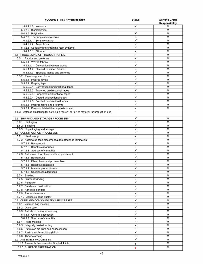
VOLUME 3 - Rev H Working Draft Status Working Group Responsibility
5.4.2.4.2 Novolacs M 5.4.2.5 Bismaleimide M 5.4.2.6 Polyimides M 5.4.2.7 Thermoplastic materials M 5.4.2.7.1 Semi crystalline M 5.4.2.7.2 Amorphous M 5.4.2.8 Specialty and emerging resin systems M 5.4.2.8.1 Silicone M 5.5 PROCESSING OF PRODUCT FORMS M 5.5.1 Fabrics and preforms M 5.5.1.1 Woven fabrics M 5.5.1.1.1 Conventional woven fabrics M 5.5.1.1.2 Stitched or knitted fabrics M 5.5.1.1.3 Specialty fabrics and preforms M 5.5.2 Preimpregnated forms M 5.5.2.1 Prepreg roving M 5.5.2.2 Prepreg tape M 5.5.2.2.1 Conventional unidirectional tapes M 5.5.2.2.2 Two-step unidirectional tapes M 5.5.2.2.3 Supported unidirectional tapes M 5.5.2.2.4 Coated unidirectional tapes M 5.5.2.2.5 Preplied unidirectional tapes M 5.5.2.3 Prepreg fabric and preforms M 5.5.2.4 Preconsolidated thermoplastic sheet M
5.5.3 Detailed guidelines for defining a "batch" or "lot" of material for production use
5.6 SHIPPING AND STORAGE PROCESSES M 5.6.1 Packaging M 5.6.2 Shipping M 5.6.3 Unpackaging and storage M 5.7 CONSTRUCTION PROCESSES M 5.7.1 Hand lay-up M 5.7.2 Automated tape placement/automated tape lamination M 5.7.2.1 Background M 5.7.2.2 Benefits/capabilities M 5.7.2.3 Sources of variability M 5.7.3 Automated tow placement/fiber placement M 5.7.3.1 Background M 5.7.3.2 Fiber placement process flow M 5.7.3.3 Benefits/capabilities M 5.7.3.4 Material product forms M 5.7.3.5 Special considerations M 5.7.4 Braiding M 5.7.5 Filament winding M 5.7.6 Pultrusion M 5.7.7 Sandwich construction M 5.7.8 Adhesive bonding M 5.7.9 Prebond moisture M 5.7.10 Adhesive bond quality M 5.8 CURE AND CONSOLIDATION PROCESSES M 5.8.1 Vacuum bag molding M 5.8.2 Oven cure M 5.8.3 Autoclave curing processing M 5.8.3.1 General description M 5.8.3.2 Sources of variability M 5.8.4 Press molding M 5.8.5 Integrally heated tooling M 5.8.6 Pultrusion die cure and consolidation M 5.8.7 Resin transfer molding (RTM) M 5.8.8 Thermoforming M 5.9 ASSEMBLY PROCESSES M 5.9.1 Assembly Processes for Bonded Joints r M
5.9.5 SURFACE PREPARATION r M
Volume 345

VOLUME 3 - Rev H Working Draft Status Working Group Responsibility
5.10 PROCESS CONTROL M 5.10.1 Common process control schemes M 5.10.1.1 Empirical methods M 5.10.1.2 Active sensor based control M 5.10.1.3 Passive model based control M 5.10.2 Example - autoclave cure of a thermoset composite M 5.10.2.1 Degree of cure M 5.10.2.2 Viscosity M 5.10.2.3 Resin pressure M 5.10.2.4 Void prevention M 5.10.2.5 Flow M 5.11 PREPARING MATERIAL AND PROCESSING SPECIFICATIONS M 5.11.1 Types of specifications M 5.11.1.1 Material specifications M 5.11.1.2 Process specs - controls end product M 5.11.2 Format for specifications M 5.11.2.1 Scope M 5.11.2.2 Applicable documents M 5.11.2.3 Technical requirements/process controls M 5.11.2.4 Receiving inspection and qualification testing M 5.11.2.5 Delivery M 5.11.2.6 Notes M 5.11.2.7 Approved sources and other M 5.11.3 Specification examples M 5.11.3.1 Industry M 5.11.3.2 Military M 5.11.4 Configuration management M 5.12 Determining sources of variability during a composite material qualification M 5.12.1 Introduction M 5.12.1.1 Composite material property variability from sources other than batch M 5.12.1.2 Conventional qualification and allowables calculation M 5.12.2 Development and application of the nested qualification approach M 5.12.2.1 Development background M 5.12.2.1.1 Regression approach M 5.12.2.1.2 Crossplied testing M 5.12.2.1.3 General aviation "AGATE" process lot approach M 5.12.2.1.4 Single panel testing M 5.12.2.1.5 Nested experiments M 5.12.2.2 Carbon/epoxy qualification approach M 5.12.2.3 Data review M 5.12.2.4 Data analysis M 5.12.2.4.1 Tension M 5.12.2.4.2 Compression M 5.12.2.4.3 Glass transition temperature M 5.12.2.5 Nested development review and conclusions M
5.12.3 Example of nested qualification data allowables calculation results using regression
M
5.12.4 Qualification of Vendor C manufacturing Vendor A material M 5.12.4.1 Introduction M 5.12.4.2 Qualification layout M 5.12.4.3 Autoclave cure schedule for process lots M 5.12.4.4 Process and test lot schedule M 5.12.4.5 Vendor C S2 G/Ep material sources of variability M 5.12.4.6 Summary M 5.12.5 Design allowables using nested approach M 5.12.6 Nested qualification cost issues M 5.12.7 Summary M 5.13 GENERIC BASIS VALUES AND EQUIVALENCE CRITERIA S
CHAPTER 6 QUALITY CONTROL OF PRODUCTION MATERIALS AND PROCESSES 6.1 INTRODUCTION M 6.2 MATERIAL PROCUREMENT QUALITY ASSURANCE PROCEDURES M 6.2.1 Specifications and documentation M
Volume 346

VOLUME 3 - Rev H Working Draft Status Working Group Responsibility
6.2.2 Material control at the supplier level M 6.2.2.1 Process control documents (PCD) M 6.2.2.2 Statistical process control (SPC) M 6.2.2.3 Lot release testing M 6.2.3 Material control at the user level M 6.2.3.1 Lot acceptance/receiving inspection M 6.2.3.2 Shelf life and out time control M 6.3 PART FABRICATION VERIFICATION M 6.3.1 Process verification M 6.3.2 Nondestructive inspection (NDI) M 6.3.3 Destructive tests (DT) M 6.3.3.1 Background M 6.3.3.2 Usage M 6.3.3.3 Destructive test approaches M 6.3.3.4 Implementation guidelines M 6.3.3.5 Test types M 6.4 Managing Change in Materials and Processes M 6.4.1 Introduction M 6.4.2 Qualification of new materials or processes M 6.4.2.1 Problem statement M 6.4.2.2 Business case M 6.4.2.3 Divergence and risk M 6.4.2.4 Technical acceptability M 6.4.2.5 Allowables development and equivalency validation M 6.4.2.6 Production readiness M 6.4.2.7 Lessons learned M 6.4.3 Divergence and risk M 6.4.3.1 Divergence M 6.4.3.2 Risk assessment M 6.4.3.3 Risk analysis M 6.4.4 Production readiness M 6.5 STATISTICAL tools for improving processes M 6.5.1 Process feedback adjustment M 6.5.2 Design of experiments M 6.5.3 Taguchi M
CHAPTER 7 DESIGN OF COMPOSITES
7.1 OVERVIEW OF UNIQUE ISSUES ASSOCIATED WITH COMPOSITE DESIGN G 7.2 DESIGN PROCESS G 7.3 MATERIAL AND PROCESS SELECTION G 7.3.1 Materials selection G 7.3.2 Manufacturing process selection G 7.3.3 Quality control G 7.3.4 Producibility G 7.3.5 Tooling G 7.3.6 Environmental effects G 7.4 STRUCTURAL CONCEPTS G 7.4.1 Solid laminate vs. sandwich vs. stiffened structure f G 7.4.2 Layup selection G 7.4.3 Tailored properties G 7.4.4 Hybrid Structure Design G 7.5 DETAILED PART DESIGN G 7.5.1 Elastic properties G 7.5.2 Laminate design considerations G 7.5.3 Thermal compatibility/low CTE G 7.5.4 Composite/metal interfaces G 7.5.5 Design for supportability G 7.5.6 Design of joints G 7.5.6.1 Mechanically-fastened joints G 7.5.6.2 Bonded joints G
7.5.6.2.1 Problems associated with adhesive bonding to peel-ply composite surfaces
G
7.5.7 Damage resistance/tolerance G 7.5.8 Durability G
Volume 347

VOLUME 3 - Rev H Working Draft Status Working Group Responsibility
7.5.9 Lightning strike f G 7.6 OPTIMIZATION G 7.7 LESSONS LEARNED G
CHAPTER 8 ANALYSIS OF LAMINATES 8.1 INTRODUCTION G 8.2 LAMINA PROPERTIES AND MICROMECHANICS G 8.2.1 Assumptions G 8.2.1.1 Material homogeneity G 8.2.1.2 Material orthotropy G 8.2.1.3 Material linearity G 8.2.1.4 Residual stresses G 8.2.2 Fiber composites: stress-strain properties G 8.2.2.1 Elastic properties G 8.2.2.2 Visco-elastic properties G 8.2.3 Fiber composites: physical properties G 8.2.3.1 Thermal expansion and moisture swelling G 8.2.3.2 Thermal conduction and moisture diffusion G 8.2.4 Thick composite 3-D lamina properties G 8.2.5 Determining lamina moduli from laminate moduli test data r G 8.3 LAMINATE STIFFNESS ANALYSIS G 8.3.1 Lamination theory G 8.3.2 Laminate properties G 8.3.2.1 Membrane stresses G 8.3.2.2 Bending G 8.3.2.3 Thermal expansion G 8.3.2.4 Moisture expansion G 8.3.2.5 Conductivity G 8.3.3 Usage of moduli values for analysis G 8.3.4 Thermal and hygroscopic analysis G 8.3.4.1 Symmetric laminates G 8.3.4.2 Unsymmetric laminates G 8.3.5 Thick composite 3-D laminate analysis G 8.4 LAMINATE IN-PLANE STRESS ANALYSIS G 8.4.1 Stresses and strains due to mechanical loads G 8.4.2 Stresses and strains due to temperature and moisture G 8.4.3 Netting analysis G 8.4.3.1 Netting analysis for design of filament wound pressure vessels G 8.4.4 Nonlinear stress analysis G 8.5 GENERAL LAMINATE STRENGTH CONSIDERATIONS G 8.5.1 Lamina strength and failure modes G 8.5.1.1 Axial tensile strength G 8.5.1.1.1 Weakest link failure G 8.5.1.1.2 Cumulative weakening failure G 8.5.1.1.3 Fiber break propagation failure G 8.5.1.1.4 Cumulative group mode failure G 8.5.1.2 Axial compressive strength G 8.5.1.3 Matrix mode strength G 8.5.2 Laminate level failure modes G 8.5.2.1 Tension G 8.5.2.2 Compression G 8.5.2.3 Matrix cracks G 8.5.3 Effects of transverse tensile properties in unidirectional tape G 8.5.4 Effect of stacking sequence on strength G 8.5.5 Lamina versus laminate strength G 8.6 LAMINATE IN-PLANE STRENGTH PREDICTION G 8.6.1 Lamina to laminate analysis approach G 8.6.1.1 Initial lamina failure G 8.6.1.2 Subsequent failures G 8.6.2 Fiber failure approach (laminate level failure) G 8.6.2.1 Maximum strain theory for glass fiber composites G 8.6.2.2 Truncated maximum strain theory for carbon fiber composites G 8.6.2.3 Strength values for use with maximum strain theory G
Volume 348

VOLUME 3 - Rev H Working Draft Status Working Group Responsibility
8.6.3 Laminate strength prediction at stress concentrations G 8.7 INTRA- AND INTER-LAMINAR STRESS AND FAILURE ANALYSIS G 8.7.1 Out-of-plane loads G 8.7.2 Interlaminar stresses G 8.7.2.1 Edge effects G 8.7.2.2 Internal ply drop-offs G 8.7.2.3 Interlaminar stresses in curved laminates G 8.7.3 Delamination G 8.7.3.1 Compression G 8.7.4 Calculation of strain energy release rate interlaminar fracture mechanics G 8.7.4.1 Introduction G 8.7.4.2 Major steps in determination of G G 8.7.4.2.1 Definition of delamination in finite element model G 8.7.4.2.1.1 Delamination location selection G 8.7.4.2.1.2 Element selection G 8.7.4.2.1.3 Mesh refinement G 8.7.4.2.1.4 Element coordinates G 8.7.4.2.1.5 Simulation of delamination and contact G 8.7.4.2.1.6 Global-local modeling G 8.7.4.2.2 Finite element solution G 8.7.4.3 Calculation of G G 8.7.4.3.1 Virtual crack closure technique - 2-D linear continuum element G 8.7.4.3.2 Virtual crack closure technique - 2-D quadratic continuum element G 8.7.4.3.3 Virtual crack closure technique - 3-D linear continuum element G 8.7.4.3.4 Corrections for non-uniform mesh G 8.7.4.4 Determination of mode mix G 8.7.4.4.1 Finite crack advance G 8.7.4.5 Practical 2-D and 3-D applications G 8.7.5 Simulation of delamination failure using cohesive zone models - OUTLINE G
CHAPTER 9 STRUCTURAL STABILITY ANALYSES 9.1 INTRODUCTION G
9.2 COMPRESSIVE BUCKLING AND CRIPPLING G 9.2.1 Plate buckling G 9.2.1.1 Introduction G 9.2.1.2 Initial buckling G 9.2.1.3 Uniaxial loading - long plate with all sides simply supported G 9.2.1.4 Uniaxial loading - long plate with all sides fixed G 9.2.1.5 Uniaxial loading - long plate with three sides simply supported and one unloaded edge free
G
9.2.1.6 Uniaxial and biaxial loading - plate with all sides simply supported G 9.2.1.7 Uniaxial loading - plate with loaded edges simply supported and unloaded edges fixed
G
9.2.1.8 Stacking sequence effects in buckling G 9.2.2 Compression postbuckling and crippling G 9.2.2.1 Analytical models G 9.2.2.2 Crippling curve determination G 9.2.2.3 Stiffener crippling strength determination G 9.2.2.4 Effects of corner radii and fillets G 9.2.2.5 Slenderness correction G 9.2.2.6 Fatigue effects G 9.2.3 Summary G 9.3 SHEAR BUCKLING G 9.4 STIFFENED PANEL STABILITY G
CHAPTER 10 DESIGN AND ANALYSIS OF BONDED JOINTSRevised Outline G 10.1 BACKGROUND G 10.2 INTRODUCTION r G 10.3 DESIGN OF BONDED JOINTS G 10.3.1 Effects of adherend thickness: adherend failures vs. bond failures G 10.3.2 Joint geometry effects G
Volume 349

VOLUME 3 - Rev H Working Draft Status Working Group Responsibility
10.3.3 Effects of adherend stiffness unbalance G 10.3.4 Effects of ductile adhesive response G 10.3.5 Behavior of composite adherends G 10.3.6 Effects of bond defects G 10.4 ANALYSIS OF BONDED JOINTS G 10.4.1 Metallic adherend bonded joint analysis G 10.4.1.1 Joint behavior assumptions r G 10.4.1.2 Failure criteria G 10.4.1.3 Configuration-specific analysis G 10.4.2 Composite adherend bonded joint analysis G 10.4.2.1 Joint behavior assumptions G 10.4.2.2 Failure criteria G 10.4.2.3 Configuration-specfic analysis G 10.4.2.3.1 Light general aviation and other lightly loaded structure G 10.4.2.3.2 Highly-loaded skin-to-spar joints G 10.4.2.3.3 Stiffener run-outs G 10.4.2.3.4 Honeycomb ramp terminations G 10.4.2.3.5 Bonded composite repairs G 10.5 BONDED JOINT CERTIFICATION ISSUES - AIRCRAFT G 10.5.1 Process quality assurance G 10.5.2 Static strength r G 10.5.2.1 Adhesive elastic-plastic design / analysis approach G 10.5.2.2 Static strength approaches G 10.5.3 Durability G 10.5.3.1 Principles G 10.5.3.2 Environmental effects on durability G 10.5.3.3 Fatigue G 10.5.4 Damage Tolerance r G 10.5.4.1 Principles r G 10.5.4.2 Categories of bonded join anomalies r G 10.5.4.3 Assessment under cyclic loading of bonded joints r G 10.5.4.4 Residual strength assessment of bonded joints r G 10.5.5 Bonded repair G 10.5.5.1 In-service inspection of bonded joints G 10.6 BONDED JOINT CERTIFICATION / QUALIFICATION ISSUES – NON-AIRCRAFT r G
10.7 DERIVATION OF ELASTIC-PERFECTLY-PLASTIC LAP-SHEAR BONDLINESTRESS
r G
10.7.1 Governing equations r G 10.7.2 Joint conditions r G 10.7.3 Boundary conditions r G 10.7.4 Application of boundary conditions r G 10.7.4.1 Condition 1 Example r G 10.7.4.2 Condition 2a Example r G 10.7.4.3 Condition 2b Example r G 10.7.4.4 Condition 3 Example r G 10.7.4.5 Condition 4 Example r G 10.7.5 Scarf joint analysis r G
CHAPTER 11 DESIGN AND ANALYSIS OF BOLTED JOINTS 11.1 BACKGROUND G 11.2 INTRODUCTION G 11.3 ANALYSIS OF BOLTED JOINTS G 11.3.1 Load sharing in a joint G 11.3.2 Analysis of local failure G 11.3.3 Failure criteria G 11.4 DESIGN OF BOLTED JOINTS G 11.4.1 Geometry G 11.4.2 Lay-up and stacking sequence G 11.4.3 Fastener selection G 11.5 FATIGUE EFFECTS ON BOLTED JOINTS G 11.5.1 Influence of loading mode G 11.5.2 Influence of joint geometry G
Volume 350

VOLUME 3 - Rev H Working Draft Status Working Group Responsibility
11.5.3 Influence of attachment details G 11.5.4 Influence of laminate lay-up G 11.5.5 Influence of environment G 11.5.6 Influence of specimen thickness G 11.5.7 Residual strength G 11.6 TEST VERIFICATION G
CHAPTER 12 DAMAGE RESISTANCE, DURABILITY, AND DAMAGE TOLERANCE 12.1 INTRODUCTION DT 12.1.1 Principles DT 12.1.2 Composite-related issues DT 12.1.3 Aircraft damage tolerance DT 12.1.4 General guidelines DT 12.2 RULES, REQUIREMENTS AND COMPLIANCE FOR AIRCRAFT DT 12.2.1 Civil aviation regulations and guidance DT 12.2.1.1 Static strength with damage DT 12.2.1.2 Damage tolerance and fatigue DT 12.2.2 Categories of damage DT 12.2.2.1 Category 1 DT 12.2.2.2 Category 2 DT 12.2.2.3 Category 3 DT 12.2.2.4 Category 4 DT 12.2.2.5 Category 5 DT 12.2.2.6 Factors affecting placement of damage in categories DT 12.2.3 Load and damage relationships DT 12.2.4 Compliance approaches DT 12.2.4.1 Deterministic compliance method DT 12.2.4.2 Probabilistic or semi-probabilistic compliance methods DT 12.3 DESIGN DEVELOPMENT AND SUBSTANTIATION DT 12.3.1 Damage threat assessment f DT 12.3.1.1 Category 1 f DT 12.3.1.2 Category 2 f DT 12.3.1.3 Category 3 f DT 12.3.1.4 Category 4 f DT 12.3.1.5 Large damage from undefined events f DT 12.3.2 Damage design criteria f DT 12.3.2.1 Category 1 f DT 12.3.2.2 Category 2 f DT 12.3.2.3 Category 3 f DT 12.3.2.4 Category 4 f DT 12.3.2.5 Full-scale testing f DT 12.3.3 Substantiation DT 12.3.2.1 Category 1 DT 12.3.2.2 Category 2 DT 12.3.2.3 Category 3 DT 12.3.2.4 Category 4 DT 12.3.2.5 Large-scale testing DT 12.3.3.6 Considerations for Metal/Composite Hybrid Structure DT 12.3.3.6.1 Environmentally Environmentally Environmentally Environmentally - DT 12.3.3.6.2 Differing Fatigue Sensitivities DT 12.3.3.7 Other Considerations DT 12.3.4 Addressing Category 5 Damage f DT 12.3.5 Additional design development guidance DT 12.4 INSPECTION FOR DEFECTS AND DAMAGE DT 12.4.1 Aircraft in-service inspection programs DT 12.4.2 Development of damage inspection data DT 12.4.3 Development of inspection programs DT 12.4.4 Environmental deterioration and accidental damage rating systems DT 12.4.5 Fleet leader programs DT 12.4.6 Probability of detection studies DT 12.5 DAMAGE RESISTANCE DT 12.5.1 Influencing factors DT 12.5.1.1 Summary of results from previous impact studies DT
Volume 351

VOLUME 3 - Rev H Working Draft Status Working Group Responsibility
12.5.1.2 Through-penetration impacts DT 12.5.1.3 High velocity impacts f DT 12.5.1.4 Material type and form effects DT 12.5.1.5 Depth of damage DT 12.5.1.6 Laminate thickness effects DT 12.5.1.7 Structural size effects DT 12.5.1.8 Sandwich structure DT 12.5.2 Design issues and guidelines DT 12.5.2.1 Use of impact surveys for establishing critical damages DT 12.5.2.2 Structural arrangement and design details DT 12.5.2.3 Mechanical impact f DT 12.5.2.4 Bird strike f DT 12.5.2.5 Ground hail DT 12.5.2.6 In-flight hail DT 12.5.2.7 Lightning DT 12.5.2.8 Handling and step loads DT 12.5.2.9 Edge erosion DT 12.5.2.10 Fluid ingress f DT 12.5.2.11 Overheating f DT 12.5.2.12 Aging f DT 12.5.2.13 Chemical contamination f DT 12.5.2.14 Disassembly for repair f DT 12.5.3 Test issues f DT 12.5.4 Analysis methods f DT 12.6 DURABILITY AND DAMAGE GROWTH UNDER CYCLIC LOADING r DT 12.6.1 Influencing factors r DT 12.6.1.1 Cyclic stress ratio (R-Ratio) and spectrum effects r DT 12.6.1.2 Environment r DT 12.6.2 Design issues and guidelines r DT 12.6.2.1 Design details r DT 12.6.2.2 Damage tolerance considerations r DT 12.6.3 Test issues r DT 12.6.3.1 Scatter analysis of composites r DT 12.6.3.1.1 Individual Weibull method r DT 12.6.3.1.2 Joint Weibull method r DT 12.6.3.1.3 Sendeckyj equivalent static strength model r DT 12.6.3.2 Life factor approach r DT 12.6.3.3 Load enhancement factor using scatter analysis r DD 12.6.3.4 Ultimate strength approach r DD 12.6.3.5 Spectrum truncation and clipping r DD 12.6.3.6 Test environment r DD 12.6.3.7 Damage growth r DD 12.6.4 Analysis methods DD 12.6.4.1 Durability and damage onset analysis DD 12.6.4.1.1 In-plane fatigue analysis DT 12.6.4.1.2 Matrix cracking onset analysis DT 12.6.4.1.3 Delamination onset analysis DT 12.6.4.2 Damage growth analysis DD 12.6.4.2.1 Large through-penetration damage DT 12.6.4.2.2 Delaminations and disbonds DT 12.6.4.2.3 Impact damages DT 12.6.4.2.4 Cuts and gouges DT 12.6.4.3 Cumulative life prediction DD 12.6.4.4 Damage growth analysis DD 12.7 RESIDUAL STRENGTH DT 12.7.1 Influencing Factors DT 12.7.1.1 Relationships between damage resistance and residual strength DT 12.7.1.2 Structure with impact damage DT 12.7.1.2.1 Material effects DT 12.7.1.2.2 Interlaminar toughness effects DT 12.7.1.2.3 Stacking sequence effects DT 12.7.1.2.4 Laminate thickness effects DT 12.7.1.2.5 Through-thickness stitching DT
Volume 352

VOLUME 3 - Rev H Working Draft Status Working Group Responsibility
12.7.1.2.6 Sandwich structure DT 12.7.1.2.7 Impact characteristic damage states DT 12.7.1.2.8 Residual strength - compression/shear loads DT 12.7.1.2.9 Residual strength - tensile loads DT 12.7.1.2.10 Stiffened panels DT 12.7.1.3 Structure with through-penetration damage DT 12.7.1.3.1 Stitched skin/stiffener panels DT 12.7.2 Design issues and guidelines DT 12.7.2.1 Stacking sequences DT 12.7.2.2 Sandwich structure DT 12.7.3 Test issues DT 12.7.3.1 Impact tests on coupons f DT 12.7.3.2 Impact tests on stiffened panels f DT 12.7.3.3 Impact tests on sandwich panels f DT 12.7.3.4 Tests for large through-penetration damage to stiffened panels f DT 12.7.3.5 Tests for large through-penetration damage to sandwich panels f DT 12.7.4 Analysis methods DT 12.7.4.1 Large through-penetration damage DT 12.7.4.1.1 Power-Law (Mar-Lin) model DT 12.7.4.1.2 Strain softening laws DT 12.7.4.1.3 LEFM - based methods DT 12.7.4.1.4 R-curves DT 12.7.4.2 Single delaminations and disbonds DD/DT 12.7.4.2.1 Fracture mechanics approaches DD/DT 12.7.4.2.2 Sublaminate buckling methods DD/DT 12.7.4.3 Impact damages DT 12.7.4.3.1 Sublaminate buckling methods DT 12.7.4.3.2 Strain softening methods DT 12.7.4.4 Cuts and gouges DT 12.8 APPLICATIONS/EXAMPLES DT 12.8.1 Rotorcraft (Sikorsky) DT 12.8.1.1 Damage DT 12.8.1.2 Environment DT 12.8.1.3 Test loading conditions related to critical failure modes DT 12.8.1.4 Test loads - load enhancement factor (LEF) DT 12.8.1.5 Spectrum - truncation DT 12.8.1.6 Residual strength test DT 12.8.2 Commercial aircraft (Boeing 777 empennage torque boxes) DT 12.8.2.1 Durability - environmental DT 12.8.2.2 Durability - mechanical loads DT 12.8.2.3 Damage DT 12.8.2.4 Damage tolerance - "no growth" tests DT 12.8.2.5 Damage tolerance - residual strength DT 12.8.2.6 Inspection plan DT 12.8.3 General aviation (Beech Starship) DT 12.8.3.1 Introduction DT 12.8.3.2 Damage tolerance evaluation DT 12.8.3.2.1 Regulatory basis DT 12.8.3.2.2 Typical damage scenarios and related requirements DT 12.8.3.2.3 Damage source and modes DT 12.8.3.2.4 Element testing DT 12.8.3.2.5 Test results DT 12.8.3.2.6 Full scale tests DT 12.8.3.2.7 Continued airworthiness inspections DT 12.8.3.3 Service experience DT 12.8.3.4 Conclusions DT 12.8.4 Thermal loads in a business jet horizontal stabilizer (designed by Fokker) DT
12.8.5 General aviation (KC-100, KAI) DT 12.9 SUPPORTING DISCUSSIONS DT OUTLINE DT 12.9.1Compliance DT 12.9.1.1 Realistic impact energy threats to aircraft DT
Volume 353

VOLUME 3 - Rev H Working Draft Status Working Group Responsibility
12.9.2 Damage resistance DT 12.9.2.1 Development of hail threat distributions DT 12.9.3 Durability and damage growth DT 12.9.3.1 Durability and damage onset case studies DT 12.9.3.1.1 Skin/stringer disbonding strength and life DT 12.9.3.1.2 Rotor hub flexbeam fatigue life DT 12.9.3.2 Damage growth case studies DT 12.9.3.2.1 Impact damage growth testing (CEAT, Aerospatiale, et.al.) DT 12.9.4 Residual strength DT 12.9.4.1 Comparisons of closed-form predictions of unconfigured notch strength DT 12.9.4.2 NASA/Boeing ATCAS methodology for determining Mar-Lin parameters, Hc and n
DT
12.9.4.3 Examples of structural damage tolerance predictions using configuration factors
DT
12.9.4.4 Issues associated with strain-softening implementation DT 12.9.4.5 Application of strain-softening methods to notched compression DT 12.9.4.6 R-curve examples DT
CHAPTER 13 DEFECTS, DAMAGE, AND INSPECTION 13.1 Defects and Damage DT 13.1.1 Defect and damage sources DT 13.1.1.1 Manufacturing and repair DT 13.1.1.2 Service DT 13.1.2 Damage types DT 13.1.2.1 Matrix imperfections DT 13.1.2.2 Delaminations and disbonds DT 13.1.2.3 Fiber breakage DT 13.1.2.4 Cracks DT 13.1.2.5 Nicks, scratches and gouges DT 13.1.2.6 Dents DT 13.1.2.7 Puncture DT 13.1.2.8 Damaged fastener holes DT 13.1.2.9 Erosion DT 13.1.2.10 Heat damage DT 13.1.2.11 Lightning strike damage DT 13.1.2.12 Combined damages DT 13.1.2.13 Damage from fluid ingression into sandwich panels DT 13.2 Inspection Methods DT 13.2.1 Nondestructive inspection DT 13.2.1.1 Visual DT 13.2.1.2 Tap testing/lamb wave DT 13.2.1.3 Ultrasonics DT 13.2.1.4 Radiography DT 13.2.1.5 Shearography DT 13.2.1.6 Thermography DT 13.2.1.7 Moisture meters DT 13.2.1.8 Bond testers DT 13.2.1.9 Eddy current DT 13.2.2 Destructive Inspection DT 13.2.3 Examples DT 13.2.3.1 Visual inspection DT 13.2.3.2 Ultrasonic DT 13.2.3.3 Radiography DT 13.2.3.4 Shearography DT 13.2.3.5 Thermography DT 13.2.3.6 Destructive inspection (cross-sectioning) DT
CHAPTER 14 SUPPORTABILITY, MAINTENANCE, AND REPAIR
Section 14.1 Introduction R
Section 14.2 Important Considerations R
Section 14.3 Service Experience R
Section 14.4 Inspection R
Section 14.5 Damage Assessment R
Section 14.6 Repair of Composite and Metalbond Structure R
– Sections completed and sent to Yellow Pages –Blue
– Sections in work or some work performed on–Green
– Sections in work with some sub‐sections sent to yellow Pages –Green/Blue
Volume 354

VOLUME 3 - Rev H Working Draft Status Working Group Responsibility
14.6.1 Introduction R
14.6.2 Prerequisites for the repair of composite and metalbond structure R
14.6.3 Repair design and processing R
14.6.3.1 Design criteria R
14.6.3.2 Repair design and processing R
14.6.3.2.1 Introduction R
14.6.3.2.2 Damage removal and site preparation R
14.6.3.2.3 Bolted repair R
14.6.3.2.4 Bonded repair R
14.6.3.2.4.1 Repair concepts R
14.6.3.2.4.2 Repair materials R
14.6.3.2.4.3 Repair processing R
14.6.3.2.4.4 Repair examples R
14.6.3.2.5 Sandwich structure repair r R
14.6.3.4 Repair quality assurance R
14.6.4 Composite and metalbond repair substantiation R
14.6.4.1 Introduction R
14.6.4.2 Aircraft regulations and requirements R 14.6.4.2.1 Civil aircraft regulations R
14.6.4.2.2 Military aircraft requirements R
14.6.4.3 Guidance and policy statements R
14.6.4.3.1 Structural criticality and other considerations R
14.6.4.4 Structural substantiation approaches used for certification R
14.6.4.4.1 Prerequisite and design data needs R
14.6.4.4.2 Substantiation predominantly by test R
14.6.4.4.3 Substantiation by analysis supported by test R
14.6.4.5 Building block planning considerations R
14.6.4.5.1 Introduction to the building block methodology R
14.6.4.5.2 Building block substantiation approach for a structure wi r R
14.6.4.5.3 Substantiation approach for a structure with a single dam r R
14.6.4.6 Temporary or time‐limited and interim repairs R
14.6.4.7 Continued airworthiness R
14.6.4.8 Interdependencies R
14.6.4.8.1 Bolted repairs R
14.6.4.8.2 Bonded repairs R
Section 14.7 Repair Analysis R
Section 14.8 Composite Repair of Metallic Structure R
Section 14.9 Maintenance Documentation R
Section 14.10 Design for Supportability R
Section 14.11 Logistics Requirements R
Section 14.12 Bonded Repair Case Studies R
14.12.1 Introduction r R
14.12.2 Case study #1 ‐ Substantiation of metalbond process changes R
14.12.3 Case study #2 ‐ Pressurized fuselage bonded repair d R
14.12.4 Case study #3 ‐ Unpressurized fuselage bolted repair d R
14.12.5 Case study #4 ‐ Horizontal stabilizer wet lay‐up bonded repair d R
14.12.6 Case study #5 ‐ Horizontal stablizer lower skin (constant gage zone) bonded rep d R
14.12.7 Case study #6 ‐ Horizontal stabilizer lower skin (skin damage with stringer bond d R
14.12.8 Case study #7 ‐ Fan Cowl, VID damage, bonded repair r R
14.12.9 Case study #8 ‐ Transport Category Co‐bonded Fueled Wing Skin Damage r R
14.12.10 Case study #9 ‐ GA case study of bodned wing‐spar/skin damage d R
CHAPTER 15 THICK-SECTION COMPOSITES 15.1 INTRODUCTION AND DEFINITION OF THICK-SECTION SD 15.2 MECHANICAL PROPERTIES REQUIRED FOR THICK-SECTION COMPOSITE THREE-DIMENSIONAL ANALYSIS
SD
15.2.1 2-D composite analysis SD 15.2.2 3-D composite analysis SD
yellow Pages –Green/Blue
– Sections not yet worked on – Red
Volume 355

VOLUME 3 - Rev H Working Draft Status Working Group Responsibility
15.2.2.1 Unidirectional lamina 3-D properties SD 15.2.2.2 Oriented orthotropic laminate 3-D properties SD 15.2.3 Theoretical property determination SD 15.2.3.1 3-D lamina property determination SD 15.2.3.2 3-D laminate property determination SD 15.2.4 Test specimen design considerations f SD 15.3 STRUCTURAL ANALYSIS METHODS FOR THICK-SECTION COMPOSITES f SD
5.4 PHYSICAL PROPERTY ANALYSIS REQUIRED FOR THICK-SECTION COMPOSITE THREE-DIMENSIONAL ANALYSIS
f SD
15.5 PROCESS ANALYSIS METHODS FOR THICK-SECTION COMPOSITES f SD 15.6 FAILURE CRITERIA f SD
15.7 FACTORS INFLUENCING THICK-SECTION ALLOWABLES (i.e., SAFETY MARGINS)
f SD
15.8 THICK LAMINATE DEMONSTRATION PROBLEM f SD
CHAPTER 16 CRASHWORTHINESS AND ENERGY MANAGEMENT 16.1 OVERVIEW AND GENERAL GUIDELINES C 16.1.1 Section organization C 16.1.2 Principles of crashworthiness C 16.1.3 Composite-related issues C 16.1.4 Terminology C 16.1.5 Existing research and development C 16.1.6 Overview of regulating bodies and safety standards C 16.2 Numerical Round Robin Results C 16.2.1 - LS-DYNA MAT54 C 16.2.2 - LS-DYNA MAT 58 C 16.2.3 - PAM-CRASH C
CHAPTER 17 STRUCTURAL SAFETY MANAGEMENT 17.1 Introduction SM 17.1.1 Background SM 17.1.2 Purpose and scope SM 17.2 Safety risk management overview SM 17.2.1 Definitions SM 17.2.2 Process of safety risk management SM 17.2.3 Hazard identification and initial safety assessment SM 17.2.4 Risk analysis and strategies SM 17.2.5 Risk assessment and mitigation actions SM 17.3 Structural safety and regulations SM 17.3.1 Sources of information SM 17.3.2 Regulations SM 17.3.3 Guidance documents SM 17.4 Structural safety assessment considerations SM 17.4.1 Design SM 17.4.2 Manufacturing SM 17.4.3 Maintenance SM 17.4.4 Operations SM 17.4.5 Airworthiness requirements SM 17.4.6 Structural integrity SM
1.7.4.6.1 Life cycle considerations SM17.4.7 Illustration SM
1.7.4.7.1 Flight 261 SM 17.5 Structural safety management procedure SM 17.5.1 Describe structure SM 17.5.2 Identify unsafe conditions and damage threats SM 17.5.3 Analyze risk SM 17.5.4 Assess risk SM 17.5.5 Mitigate risk SM 17.6 Structural safety management applications SM 17.6.1 Application: implication of less reliance on OEMs for repaired parts SM 17.6.2 Application: nonconforming extensive repair involving metal bonding SM 17.6.3 Application: nonconforming extensive repair involving composite repair SM 17.7 Structural safety awareness course structure SM
Volume 356

VOLUME 3 - Rev H Working Draft Status Working Group Responsibility
CHAPTER 18 ENVIRONMENTAL MANAGEMENT 18.1 INTRODUCTION M 18.1.1 Scope M 18.1.2 Glossary of recycling terms M 18.2 RECYCLING INFRASTRUCTURE M 18.2.1 Recycling infrastructure development models M 18.2.2 Infrastructure needs M 18.2.3 Recycling education M 18.3 ECONOMICS OF COMPOSITE RECYCLING M 18.4 COMPOSITE WASTE STREAMS M 18.4.1 Process waste M 18.4.2 Post consumer composite waste M 18.5 COMPOSITE WASTE STREAM SOURCE REDUCTION M 18.5.1 Just-in-time and just enough material delivery M 18.5.2 Electronic commerce acquisition management M 18.5.3 Waste minimization guidelines M 18.5.3.1 Prepreg M 18.5.3.2 Resin M 18.5.3.3 Fiber f M 18.5.3.4 Curing agents f M 18.5.3.5 Autoclaving materials f M 18.5.3.6 Packaging materials f M 18.5.4 Lightweighting M 18.6 REUSE OF COMPOSITE COMPONENTS AND MATERIALS M 18.6.1 Reuse of composite components M 18.6.2 Machining to smaller components M 18.7 MATERIALS EXCHANGE M 18.7.1 Reallocation of precursors M 18.7.2 Composite materials exchange services M 18.7.2.1 Care of unused materials M 18.7.2.2 Packaging M 18.7.2.3 Documentation of care M 18.7.2.4 Description of unused materials M 18.7.2.5 DOD resale restrictions M 18.8 RECYCLING OF COMPOSITE MATERIALS M 18.8.1 Design for disassembly and recycling M 18.8.1.1 Fasteners M 18.8.1.2 Adhesives M 18.8.1.3 Hybrid composites M 18.8.2 Recycling logistics M 18.8.2.1 Collection and transportation M 18.8.2.2 Identification of fibers and matrices M 18.8.2.2.1 Fourier transform infrared spectroscopy M 18.8.2.2.2 Densitometry M 18.8.2.2.3 Coding of components M 18.8.2.2.4 Routing of waste streams f M 18.8.3 Processing of composite recyclate M 18.8.3.1 Size reduction M 18.8.3.2 Matrix removal M 18.8.3.3 Fiber reuse M 18.8.3.4 Products of matrix removal M 18.8.3.5 Other recycling and processing methods M 18.8.4 Recycling of waste prepreg M
CHAPTER 19 LAUNCH VEHICLES AND SPACECRAFT 19.1 LIFE CYCLE CONSIDERATIONTINTRODUCTION r P 19.2 MATERIAL SELECTION r P 19.3 DURABILITY AND DAMAGE TOLERANCE r P 19.4 SPACECRAFT SANDWICH STRUCTURE DESIGN CONSIDERATIONS P 19.4.1 Requirements and policies P 19.4.2 Managing Moisture and Internal Pressure in Spacecraft Sandwich Structure P
Volume 357

VOLUME 3 - Rev H Working Draft Status Working Group Responsibility
19.4.3 Cryogenic Sandwich Structural Design Complexities P 19.4.4 Design Substantiation Testing and Analysis P 19.5 ELECTROMAGNETIC COMPATIBILITY (EMC) P 19.6 STRUCTURAL REDUNDANCY AND FRACTURE CRITICAL STRUCTURES P
19.7 DESIGN SUBSTANTIATION P 19.8 COMPOSITE OVERWRAPPED PRESSURE VESSELS P 19.8.1 COPV design and fabrication P 19.8.2 Material allowables development P
Volume 358

VOLUME 6 Rev A Working Draft Status Working Group Responsibility
CHAPTER 1 GENERAL INFORMATION 1.1 INTRODUCTION TO THE HANDBOOK SW
1.2 OVERVIEW OF HANDBOOK CONTENT SW
1.3 INTRODUCTION SW
1.4 NOMENCLATURE AND DEFINITIONS SW
1.4.1 Loads, geometry, and material properties SW
1.4.1.1 Subscripts SW
1.4.1.2 Superscripts SW
1.4.1.3 Assumptions and definitions SW
1.4.2 System of units SW
CHAPTER 2 GUIDELINES FOR PROPERTY TESTING 2.1 INTRODUCTION SW
2.2 DATA REDUCTION AND PRESENTATION SW
2.3 EVALUATION OF CORE MATERIALS SW
2.3.1 Mechanical properties SW
2.3.2 Environmental effects SW
2.3.3 Test Methods SW
2.4 EVALUATION OF CORE-TO-FACE SHEET BONDS SW
2.4.1 Introduction SW
2.4.2 Mechanical properties SW
2.4.3 Environmental effects SW
2.4.4 Test Methods SW
2.5 EVALUATION OF FACE SHEET PROPERTIES SW
2.5.1 Introduction SW
2.5.2 Mechanical properties SW
2.5.3 Environmental effects SW
2.5.4 Test Methods SW
2.6 EVALUATION OF SANDWICH PANELS SW
2.6.1 Introduction SW
2.6.2 Mechanical properties SW
2.6.3 Environmental effects SW
2.6.4 Damage resistance SW
2.6.5 Damage tolerance SW
2.6.6 Repair SW
2.6.7 Test Methods SW
2.7 EVALUATION OF INSERTS AND FASTENERS SW
2.7.1 Introduction SW
2.7.2 Mechanical properties SW
2.7.3 Environmental effects SW
2.7.4 Test Methods SW
2.8 EVALUATION OF OTHER FEATURES SW
2.8.1 Introduction SW
2.8.2 Mechanical properties SW
2.8.3 Environmental effects SW
2.8.4 Test Methods SW
CHAPTER 3 MATERIAL DATA 3.1 CORES SW
3.1.1 Description of cores SW
3.1.2 Core specifications SW
3.1.3 Honeycomb cores SW
3.1.4 Cross-banded cores SW
3.1.5 Corrugated cores SW
3.1.6 Waffle-type cores SW
3.1.7 Foam cores SW
3.1.8 Wood cores SW
3.1.9 Core properties SW
3.1.9.1 Estimation of core properties SW
3.2 FACE SHEETS SW
Volume 659

VOLUME 6 Rev A Working Draft Status Working Group Responsibility
3.2.1 Description of face shets SW
3.2.1.1 Adhesive-bonded pre-fabricated face sheets SW
3.2.1.2 Co-cured or co-bonded face sheets with adhesive SW
3.2.1.3 Self-adhesive face sheets SW
3.2.2 Face sheet properties SW
3.3 ADHESIVES SW
3.3.1 Description of adhesives SW
3.3.2 Adhesive specifications SW
3.3.3 Adhesive forms/types and uses SW
3.3.3.1 Resins from self-adhesive face sheets SW
3.3.3.2 Film adhesives SW
3.3.3.3 Paste adhesives SW
3.3.3.4 Liquid resins SW
3.3.3.5 Foaming adhesives SW
3.3.4 Adhesive chemistries SW
3.3.4.1 Epoxy SW
3.3.4.2 Bismaleimide SW
3.3.4.3 Phenols SW
3.3.4.4 Polyester SW
3.3.4.5 Polyimide SW
3.3.5 Adhesive properties SW
CHAPTER 4 DESIGN AND ANALYSIS OF SANDWICH STRUCTURES 4.1 INTRODUCTION SW
4.2 DESIGN AND CERTIFICATION SW
4.2.1 Basic design principles SW
4.2.2 Design process SW
4.2.3 Aircraft Damage tolerance SW
4.3 CERTIFICATION SW
4.3.1 Introduction to certification issues SW
4.3.2 Approach to certification testing SW
4.3.3 Analysis validation SW
4.3.4 Conformity oversight SW
4.3.5 Nondestructive testing (NDT) SW
4.3.6 Documentation requirements SW
4.3.7 Continued airworthiness SW
4.4 SANDWICH PANEL FAILURE MODES SW
4.5 STIFFNESS AND INTERNAL LOADS SW
4.5.1 Beam stiffness analysis SW
4.5.2 Plate stiffness analysis SW
4.5.3 Combined Transverse and in-plane loadings SW
4.5.4 Face sheet internal loads SW
4.6 LOCAL STRENGTH ANALYSIS METHODS SW
4.6.1 Face sheet failure SW
4.6.2 Core shear SW
4.6.3 Flatwise tension and compression SW
4.6.4 Flexural core crushing SW
4.6.5 Intracell buckling (dimpling) SW
4.6.5.1 Sandwich having cellular (honeycomb) core SW
4.6.5.2 Sandwich having corrugated core SW
4.6.5.3 Shear intracell buckling SW
4.6.5.4 Combined compression and shear intracell buckling SW
4.6.6 Face sheet wrinkling SW
4.6.6.1 Wrinkling of sandwich face sheets under edgewise load SW
4.6.6.2 Sandwich with core supporting face sheets continuously SW
4.6.6.3 Sandwich with honeycomb core SW
4.6.6.4 Shear face sheet wrinkling SW
4.6.6.5 Face sheet wrinkling - combined loads SW
4.6.6.6 Face sheet wrinkling - curved panels SW
4.6.7 Core shear crimping SW
Volume 660

VOLUME 6 Rev A Working Draft Status Working Group Responsibility
4.6.8 Attachments and hard points SW
4.6.8.1 Design of flat circular sandwich panels loaded an an insert SW
4.7 FLAT PANEL INTERNAL LOADS AND STRESSES - PRESSURE LOADING SW
4.7.1 Design of flat rectangular sandwich beams under various normal loadings SW
4.7.2 Design of flat sandwich panels under uniformly distributed normal load SW
4.7.2.1 Determining face sheet thickness, core thickness, and core shearmodulus for simply supported flat rectangular panels under uniform load
SW
4.7.2.1.1 Use of design charts SW
4.7.2.1.2 Determining core shear stress SW
4.7.2.1.3 Checking procedures SW
4.7.2.2 Determining face sheet thickness, core thickness, and core shearmodulus for simply supported flat circular panels under uniform load
SW
4.7.2.2.1 Use of design charts SW
4.7.2.2.2 Determining core shear stress SW
4.7.2.2.3 Checking procedure SW
4.8 CURVED SANDWICH PANEL INTERNAL LOADS AND STRESSES SW
4.8.1 General equations and analysis method SW
4.9 FLAT PANEL STABILITY ANALYSIS METHODS SW
4.9.1 Buckling of flat rectangular sandwich columns SW
4.9.2 Design of flat rectangular sandwich panels under edgewise compression load SW
4.9.2.1 Determining face sheet thickness SW
4.9.2.2 Determining core thickness and core shear modulus SW
4.9.2.2.1 Determination of minimum values of d SW
4.9.2.2.2 Determination of actual values of d SW
4.9.2.3 Checking procedure for determining buckling stress, Fcr SW
4.9.3 Design of flat rectangular sandwich panels under edgewise shear load SW
4.9.3.1 Determining face sheet thickness SW
4.9.3.2 Determining core thickness and core shear modulus SW
4.9.3.2.1 Determination of minimum values of d SW
4.9.3.2.2 Determination of actual values of d SW
4.9.3.3 Checking procedure for determining buckling stress, Fcr SW
4.9.4 Design of sandwich strips under torsion load SW
4.9.4.1 Determining face sheet thickness, core thickness and core shearmodulus for sandwich strips of trapezoidal and rectangular cross section
SW
4.9.4.1.1 Determination of minimum values of d and t SW
4.9.4.1.2 Determination of actual values of d and t SW4.9.4.1.3 Checking procedure for sandwich strips of trapezoidal and
rectangular cross section SW
4.9.4.2 Determining face sheet thickness, core thickness and core shearmodulus for sandwich strips of triangular cross section
SW
4.9.4.2.1 Determination of minimum values of t SW
4.9.4.2.2 Determination of actual values of t SW4.9.5 Design of flat rectangular sandwich panels under edgewise bending
moment SW
4.9.5.1 Determining face sheet thickness SW
4.9.5.2 Determining core thickness and core shear modulus SW
4.9.5.2.1 Determination of minimum values of d SW
4.9.5.2.2 Determination of actual values of d SW
4.9.5.3 Checking procedure for determining buckling stress, Fcr SW4.10 DESIGN OF FLAT RECTANGULAR SANDWICH PANELS UNDER
COMBINED LOADS SW
4.10.1 Combined load buckling SW 4.10.1.1 Biaxial compression SW 4.10.1.2 Bending and compression SW 4.10.1.3 Compression and shear SW
Volume 661

VOLUME 6 Rev A Working Draft Status Working Group Responsibility
4.10.1.4 Bending and shear SW 4.10.2 Combined in-plane and transverse loads SW 4.11 DESIGN OF SANDWICH CYLINDERS SW 4.11.1 Introduction SW 4.11.2 Sandwich cylinders under external radial pressure SW 4.11.2.1 Determining face sheet thickness, core thickness, and coreshear modulus for sandwich cylinders under external radialpressure
SW
4.11.2.2 Final design SW 4.11.3 Sandwich cylinders under torsion SW
4.11.2.1 Determining facesheet thickness, core thickness, and one core shear modulus to sandwich cylinders under external radial pressure
SW
4.11.2.2 Final design SW 4.11.3 Sandwich cylinders under torsion SW
4.11.3.1 Determining face sheet thickness for sandwich cylinders undertorsion
SW
4.11.3.2 Determining core thickness and core shear modulus forsandwich cylinders under torsion
SW
4.11.3.3 Check to determine whether sideways buckling will occur SW 4.11.4 Sandwich cylinders under axial compression or bending SW
4.11.4.1 Determining facesheet thickness, core thickness, and core shear modulus
SW
4.11.4.2 Checking procedure for determining cylinder wall buckling stress, Fcr SW
4.11.4.3 Check to determine whether column buckling will occur SW4.11.5 Sandwich cylinders under combined loads SW
4.11.5.1 Axial compression and external lateral pressure SW4.11.5.2 Axial compression and torsion SW4.11.5.3 Torsion and lateral external or internal pressure SW
4.12 FINITE ELEMENT MODELING OF SANDWICH STRUCTURE SW
4.12.1 Introduction SW
4.12.2 Global models SW
4.12.3 Layered models SW
4.12.4 Solid models SW
4.12.5 Sandwich element models SW
4.13 Optimum sandwich SW
4.13.1 Sandwich weight SW
4.13.2 Sandwich bending stiffness SW
4.13.3 Sandwich bending moment capacity SW
4.13.4 Sandwich panel buckling SW
CHAPTER 5 FABRICATION OF SANDWICH STRUCTURES5.1 INTRODUCTION SW
5.2 MATERIALS SW
5.2.1 Cores SW
5.2.2 Face sheets SW
5.2.3 Adhesives SW
5.2.4 Surfacing and sealing SW
5.3 PROCESSES SW
5.3.1 Core SW
5.3.1.1 Cleaning SW
5.3.1.2 Drying SW
5.3.1.3 Forming SW
5.3.1.4 Splicing SW
5.3.1.5 Potting SW
5.3.1.6 Septums SW
5.3.1.7 Core stabilization for machining SW
5.3.1.8 Machining SW
5.3.1.9 Tolerances SW
5.3.2 Face sheets - co-cure vs. pre-cure and resin pressure SW
5.3.3 Adhesive SW
5.3.3.1 Impression check SW
Volume 662

VOLUME 6 Rev A Working Draft Status Working Group Responsibility
5.3.3.2 Bonding SW
5.3.3.3 Filleting SW
5.4 HONEYCOMB CORE CRUSH SW
5.4.1 Core crush during cure SW
5.4.2 Core crush - theoretical discussion SW
5.4.3 Core crush stabilization for cure SW
5.4.4 Core material characteristics and core crush SW
5.4.5 Prepreg and adhesive material characteristics and core crush SW
5.4.6 Cure cycles and core crush SW
5.4.7 Quality issues including nondestructive evaluation (NDI) SW
CHAPTER 6 QUALITY CONTROL 6.1 INTRODUCTION r SW
6.2 MATERIAL PROCUREMENT QUALITY ASSURANCE PROCEDURES r SW
6.2.1 Specifications and documentation r SW
6.2.2 Receiving inspection r SW
6.3 PART FABRICATION VERIFICATION r SW
6.3.1 Process verification r SW
6.3.2 Nondestructive inspection r SW
6.3.3 Destructive tests r SW
6.4 STATISTICAL PROCESS CONTROL r SW
6.5 MANAGING CHANGE IN MATERIALS AND PROCESSES r SW
CHAPTER 7 SUPPORTABILITY 7.1 INTRODUCTION SW
7.2 DESIGN FOR SUPPORTABILITY SW
7.2.1 In-service experience SW
7.2.2 Inspectability SW
7.2.3 Material selection SW
7.2.4 Damage resistance SW
7.2.5 Environmental compliance SW
7.2.6 Reliability and maintainability SW
7.2.7 Repairability SW
7.3 SUPPORT IMPLEMENTATION SW
7.3.1 Part inspection SW
7.3.2 Damage assessment SW
7.3.3 Repair design criteria SW
7.3.4 Repair of composite structures SW
7.3.4.1 Damage removal and site preparation SW
7.3.4.2 Bonded repairs SW
7.3.4.3 Repair analysis SW
7.3.4.4 Repair procedures SW
7.3.4.5 Repair inspection SW
7.3.4.6 Repair validation SW
7.4 LOGISTICS REQUIREMENTS SW
Volume 663

64
COMPOSITE MATERIALS HANDBOOK 17
INFORMATION ACCESS

65
INFORMATION ACCESS
HOMEPAGE
The World Wide Web homepage for the handbook is located at http://www.cmh17.org.
The Working Group Web Site is located at https://www.cmh17.org. A password can be obtained through
the Secretariat ([email protected]). Any active participant can obtain a password.
Coordination Group approved Proceedings, meeting information, RECIPE and other information are
available at the website.
OBTAINING CMH-17
VOLUMES 1 and 3 REVISION G (2012), 2 REVISION H (2018), Volume 4B (2013), Volume 5A (2017)
Volume 6 (2013)
Copies of published versions of CMH-17 Volumes 1, 2, 3, 4, 5 and 6 can be obtained from SAE only. SAE
(http://store.sae.org/cmh-17/) offers a hardcopy version of the five volumes of the handbook (Volumes
1 and 3 – G, 2-H, 4-B, 6). Print and e-book versions are available.
SOFTWARE – CMH17-STATS
The statistical methods included in the Composite Materials Handbook are available in the newly released
software - CMH17 STATS. This software (Excel based) is approved for use in CMH-17. For more
information or to purchase CMH17 STATS, visit the online store –
http://cmh17.org/RESOURCES/StatisticsSoftware.aspx
Update: 10/30/2018

66
COMPOSITE MATERIALS HANDBOOK 17
IMPORTANT DATES

67
IMPORTANT DATES
COMPOSITE MATERIALS HANDBOOK PMC COORDINATION July 2020 THROUGH March 2021 DUE DATES
July 2020 PMC Coordination Meeting
July 6 – 21, 2020 - Virtual
August
August 28 - Minutes, Yellow Pages and
Presentations due to Secretariat (PMC) –
send to [email protected]
September
September 21 – Proceedings and 1st Yellow
Page cycle complete and posted on website
October October 23, 2020 – 1st Yellow Page ballot
comments due to Secretariat (PMC)
November
December 2nd Yellow Pages Ballot posted – tentative
January 2021
February 2nd Yellow Page Cycle ballot and comments
due to Secretariat - tentative
March
March 8 – 12, 2021
PMC Coordination Meeting, University of
Utah, Salt Lake City, UT (in conjunction
with ASTM D30)

68
COMPOSITE MATERIALS HANDBOOK 17
CHAIRS AND COORDINATORS

69
CMH-17 PMC CHAIRS AND COORDINATORS CMH-17 and PMC Coordination Group Chair Dr. Larry Ilcewicz FAA Aircraft Certification Service, Policy and Innovation Division 2200 S 216th St, 3W-450 Des Moines, WA 98198 Tel: 206-231-3147 Email: [email protected]
CMH-17 and PMC Coordination Group Chair Mr. Curtis R. Davies Federal Aviation Administration FAA Technical Center, ANG-E231 Atlantic City Intl. Airport, NJ 08405 Tel: 609-485-8758 Fax: 609-485-4004 Email: [email protected]
CMH-17 Industry Chair Dr. Carl Q. Rousseau Lockheed Martin Aeronautics P.O. Box 748, MZ 6516 Fort Worth, TX 76101 Tel: 817-763-7727 Fax: 817-762-5673 Email: [email protected]
CMH-17 Industry Chair Mr. Stephen H. Ward Collins Aerospace 850 Lagoon Drive Chula Vista, CA 91910 Tel: 619-691-2811 Email: [email protected]
CMH-17 Secretariat Wichita State University 1845 Fairmount Wichita, KS 67260-0093 Tel: 316-218-2773 Email: [email protected]
WORKING GROUP CHAIRS
Bonding Process Cochair (Task Group under M&P) Dr. Howard Creel 3M Automotive and Aerospace Solutions Division 3M Center, 280-2W-21 | St. Paul, MN 55144 Tel: 651-737-9955 Email: [email protected]

70
Bonded Joints Cochair (Task Group under Guidelines) Mr. Rick Cole National Research Council Canada (NRC) Building M-3, 1200 Montreal Road, Ottawa, Ontario, Canada K1A 0R6 Tel: 613-993-4058 Fax: 613-998-8609 E-mail: [email protected]
Bonded Joints Cochair (Task Group under Guidelines) Dr. Carl Q. Rousseau Lockheed Martin Aeronautics P.O. Box 748, MZ 6516 Fort Worth, TX 76101 Tel: 817-763-7727 Fax: 817-762-5673 Email: [email protected]
Certification Cochair (Task Group under Guidelines) Dr. Simon Waite European Aviation Safety Agency (EASA) 1 Ottoplatz Koln 50679 GERMANY Tel: 49-221-89990 4082 Fax: 49-221 89990 4582 Email: [email protected]
Certification Cochair (Task Group under Guidelines) Ms. Cindy Ashforth Federal Aviation Administration 2200 S. 216th Street Des Moines, WA 98198 Tel: 206-231-3239 Email: [email protected]
Composites for Spacecraft Cochair Mr. Jeffrey D. Eichinger Boeing 5301 Bolsa Avenue Huntington Beach, CA 92647 Tel: 714-317-0394 Fax: Email: [email protected]
Composites for Spacecraft Cochair Mr. Jeremy Jacobs NASA Johnson Space Center 2101 Nasa Parkway, M.S. ES4 Houston, TX 77058 Tel: 281-483-8825 Fax: Email: [email protected]
Core Cochair (Task Group under Sandwich) Dr. Susan Daggett Absolute Value, LLC. Tel: 912-650-0693 Email: [email protected]
Core Cochair (Task Group under Sandwich) Mr. Shannon Jones Bell Helicopter Textron Email: [email protected]
Crashworthiness Cochair Mr. Allan Abramowitz Email: [email protected]
Crashworthiness Cochair Dr. Mostafa Rassaian PO Box 6683 Bellevue, WS 98008-0683 Tel: 206-715-6358 Email: [email protected]

71
Damage Tolerance Cochair (Task Group under Safety Management) Dr. Douglas S. Cairns Montana State University Mechanical & Industrial Engineering 220 Roberts Hall Boseman, MT 59717 Tel: 406-994-0393 Fax: 406-539-6292 Email: [email protected]
Damage Tolerance Cochair (Task Group under Safety Management) Mr. Patrick Enjuto Boeing Email: [email protected]
Damage Tolerance Cochair (Task Group under Safety Management) Mr. Allen Fawcett Email: [email protected]
Damage Tolerance Cochair (Task Group under Safety Management) Mr. Mike Smeets Fokker Landing Gear Grasbeemd 28 Helmond 5705 DG The Netherlands Tel: 31 0 492-575286 Email: [email protected]
Damage Tolerance Cochair (Task Group under Safety Management) Dr. Simon Waite European Aviation Safety Agency (EASA) Postfach 10 12 53 Koln D-50452 GERMANY Tel: 49-221-89990 4082 Fax: 49-221 89990 4582 Email: [email protected]
Data Review Cochair Mr. Curtis R. Davies Federal Aviation Administration FAA Technical Center Atlantic City Intl. Airport, NJ 08215 Tel: 609-485-8758 Fax: 609-485-4004 Email: [email protected]
Data Review Cochair Dr. John S. Tomblin Wichita State University 1845 Fairmount Wichita, KS 67260-0093 Tel: 316-978-5234 Fax: 316-978-3175 Email: [email protected]

72
Disbonding and Delamination Cochair (Task Group under Safety Management) Ms. Lisa McHugh Northrop Grumman 1 Hornet Way M/C 902/W2 El Segundo, CA 90245 Tel: 310-332-6352 Fax: Email: [email protected]
Disbonding and Delamination Cochair (Task Group under Safety Management) Dr. Ronald Krueger National Institute of Aerospace (NIA) NASA Langley Research Center Mail Stop 188E Hampton, VA 23681-2199 Tel: 757-864-3482 Fax: 757-864-8911 Email: [email protected]
Guidelines Cochair Dr. Carl Q. Rousseau Lockheed Martin Aeronautics P.O. Box 748, MZ 6516 Fort Worth, TX 76101 Tel: 817-763-7727 Fax: 817-762-5673 Email: [email protected]
Guidelines Cochair Mr. Stephen H. Ward Collins Aerospace 850 Lagoon Drive Chula Vista, CA 91910 Tel: 619-691-2811 Email: [email protected]
Materials & Processes Cochair Dr. Margaret E. Roylance Nano Tech Labs Tel: 617- 930-6572 Email: [email protected]
Materials & Processes Cochair Mr. Daniel R. Ruffner Email: [email protected]
P17 Cochair (Task Group under M&P) Mr. Shannon Jones Bell Helicopter Textron Email: [email protected]
Safety Management Cochair Ms. Cindy Ashforth FAA Aircraft Certification Service, Policy and Innovation Division 2200 S. 216th Street Des Moines, WA 98198 Tel: 206-231-3239 Email: [email protected]
Safety Management Cochair Dr. Larry Ilcewicz FAA Aircraft Certification Service, Policy and Innovation Division 2200 S 216th St, 3W-450 Des Moines, WA 98198 Tel: 206-231-3147 Email: [email protected]

73
Sandwich Cochair Mr. Lawrence A. Gintert Independent Consultant 3 Cross St, Apt 1 Jaffrey, NH 03452 Tel: 727-403-5769 Email: [email protected]
Sandwich Cochair Dr. Melanie G. Violette Federal Aviation Administration 2200 S 216th St Des Moines, WA 98198 Tel: 206-231-3506 Email: [email protected]
Sandwich Cochair Dr. Zhi Chen Email: [email protected]
Statistics Cochair Mr. Curtis R. Davies Federal Aviation Administration FAA Technical Center, ANG-E231 Atlantic City Intl. Airport, NJ 08405 Tel: 609-485-8758 Fax: 609-485-4004 Email: [email protected]
Statistics Cochair Dr. Elizabeth Clarkson WSU/NIAR 1845 Fairmount Box 93 Wichita, KS 67260 Tel: 316-978-3952 Fax: 316-978-3175 Email: [email protected]
Supportability, Maintenance, and Repair Cochair Dr. Joseph Rakow Exponent Failure Analysis Associates 149 Commonwealth Drive Menlo Park, CA 94025 Tel: 650-688-7316 Fax: 650-688-7231 Email: [email protected]
Supportability, Maintenance, and Repair Cochair Mr. Stephen Starnes US Navy 101 Wasp Street Jacksonville, FL 32212-0016 Tel: 904-790-6410 Email: [email protected]
Testing Cochair Dr. Daniel O. Adams University of Utah 50 S. Central Campus Drive Room 2110 MEB Salt Lake City, UT 84112 Tel: 801-585-9807 Fax: 801-585-9826 Email: [email protected]
Testing Cochair Mr. John Moylan Element Materials Technologies 1857 Business Center Dr Duarte, CA 91010 Tel: 818-296-0444 Email: [email protected]


