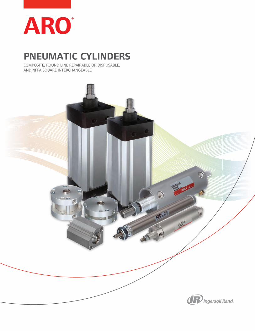
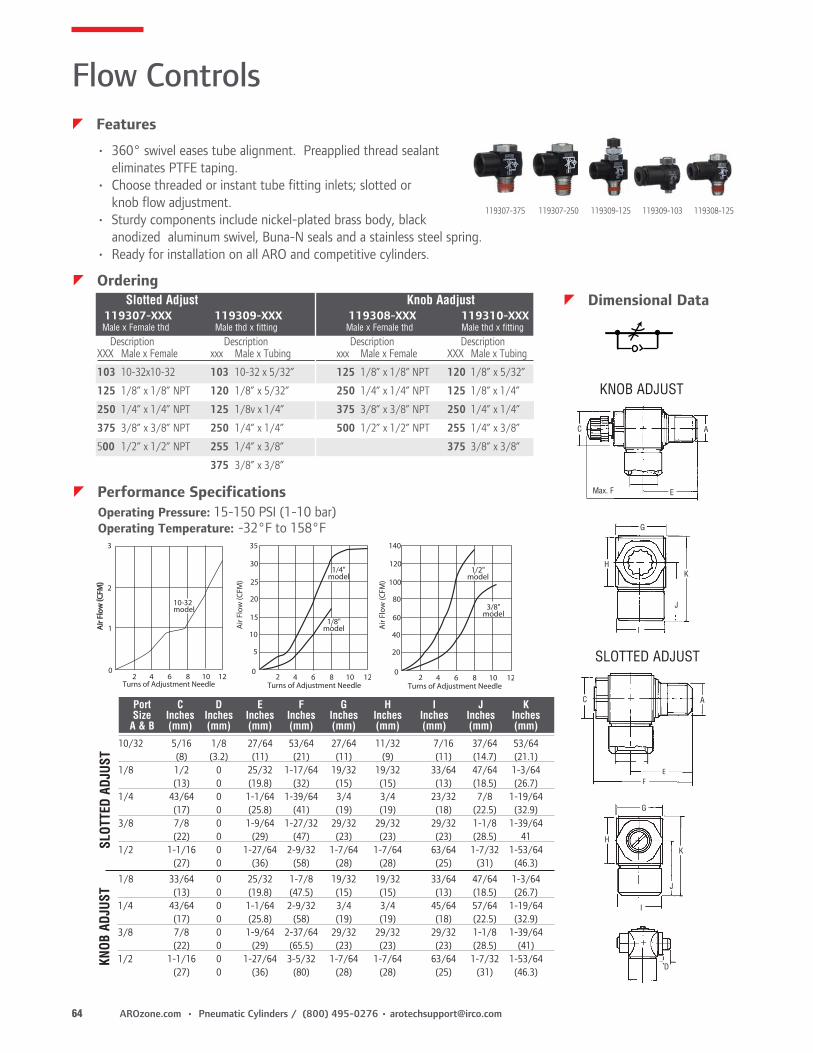
Pneumatic Cylinders Composite, round line repairable and disposable, and NFPA square interchangeable PNEUMATIC CYLINDERS COMPOSITE, ROUND LINE REPAIRABLE OR DISPOSABLE, AND NFPA SQUARE INTERCHANGEABLE
Transcript
Pneumatic CylindersComposite, round line repairable and disposable, and NFPA square interchangeable
PNEUMATIC CYLINDERSCOMPOSITE, ROUND LINE REPAIRABLE OR DISPOSABLE,AND NFPA SQUARE INTERCHANGEABLE
About ARO®ARO® is a worldwide manufacturer of fluid management products that are skill-fully engineered to deliver performance and serviceability, allowing success to flow freely in our customers’ businesses. That’s why ARO is fluid intelligence—the smart choice in fluid management products for industrial operations.
With over an 85-year legacy of premier product performance and service excel-lence, ARO provides fluid management equipment for customers and industries around the globe; including chemical, manufacturing, energy, pharmaceutical, min-ing and more.
ARO has the right product to meet our customers’ specific needs. We offer air-operated diaphragm pumps, piston pumps and packages, filters, regulators, and lubricators (FRLs), lubrication equipment, and pneumatic valves and cylinders.
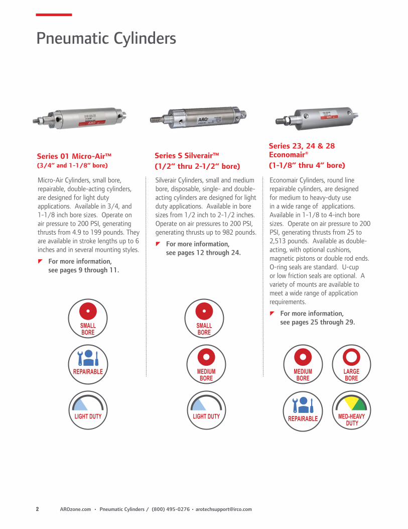
Silverair Cylinders, small and medium bore, disposable, single- and double-acting cylinders are designed for light duty applications. Available in bore sizes from 1/2 inch to 2-1/2 inches. Operate on air pressures to 200 PSI, generating thrusts up to 982 pounds.
zFor more information, see pages 12 through 24.
Series 01 Micro-Air™(3/4” and 1-1/8” bore)
Micro-Air Cylinders, small bore, repairable, double-acting cylinders, are designed for light duty applications. Available in 3/4, and 1-1/8 inch bore sizes. Operate on air pressure to 200 PSI, generating thrusts from 4.9 to 199 pounds. They are available in stroke lengths up to 6 inches and in several mounting styles.
z For more information, see pages 9 through 11.
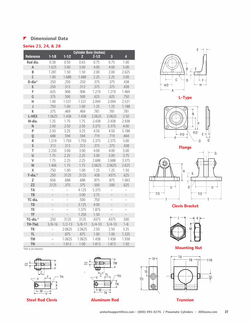
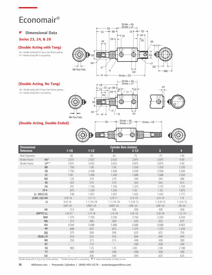
Series 23, 24 & 28Economair®(1-1/8” thru 4” bore)
Economair Cylinders, round line repairable cylinders, are designed for medium to heavy-duty use in a wide range of applications. Available in 1-1/8 to 4-inch bore sizes. Operate on air pressure to 200 PSI, generating thrusts from 25 to 2,513 pounds. Available as double-acting, with optional cushions, magnetic pistons or double rod ends. O-ring seals are standard. U-cup or low friction seals are optional. A variety of mounts are available to meet a wide range of application requirements.
zFor more information, see pages 25 through 29.REPAIRABLESMALL
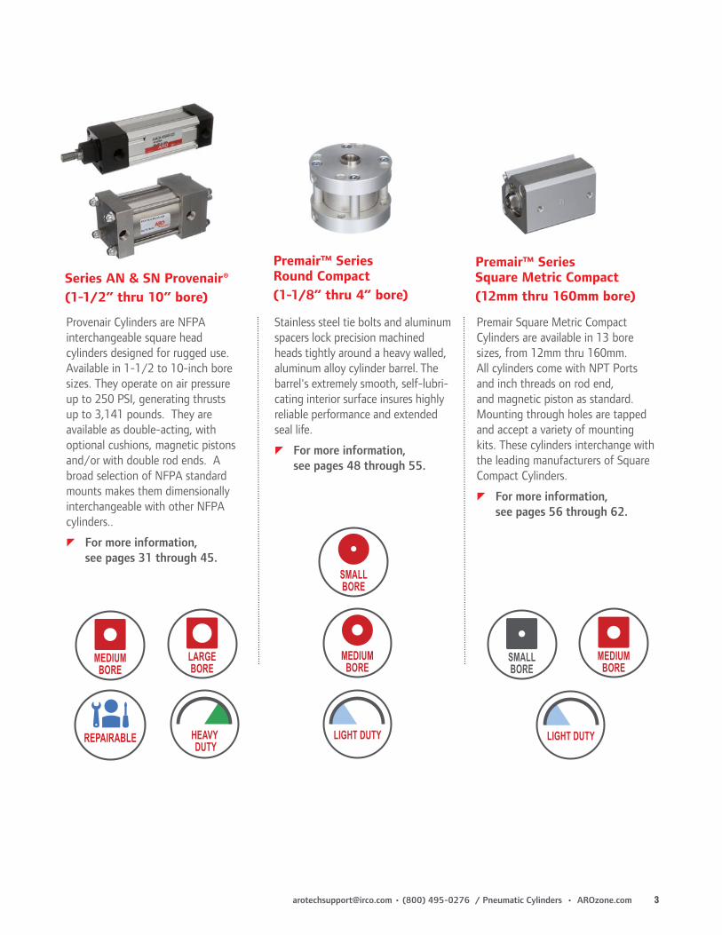
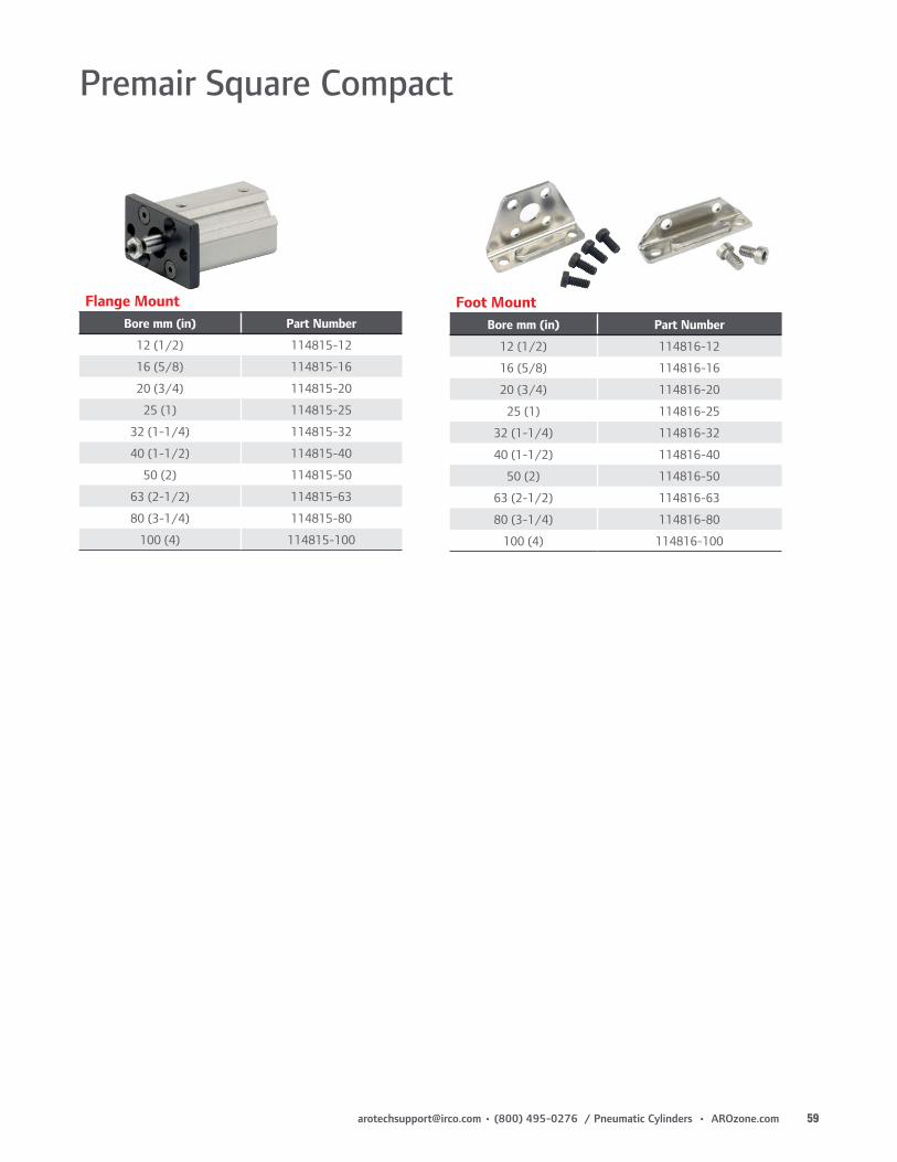
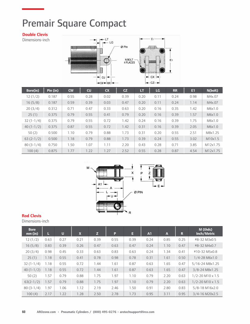
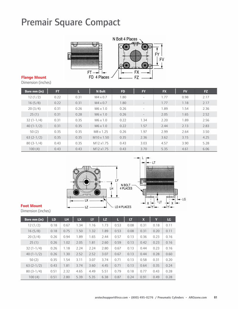
Premair™ Series Round Compact(1-1/8” thru 4” bore)
Stainless steel tie bolts and aluminum spacers lock precision machined heads tightly around a heavy walled, aluminum alloy cylinder barrel. The barrel's extremely smooth, self-lubri-cating interior surface insures highly reliable performance and extended seal life.
zFor more information, see pages 48 through 55.
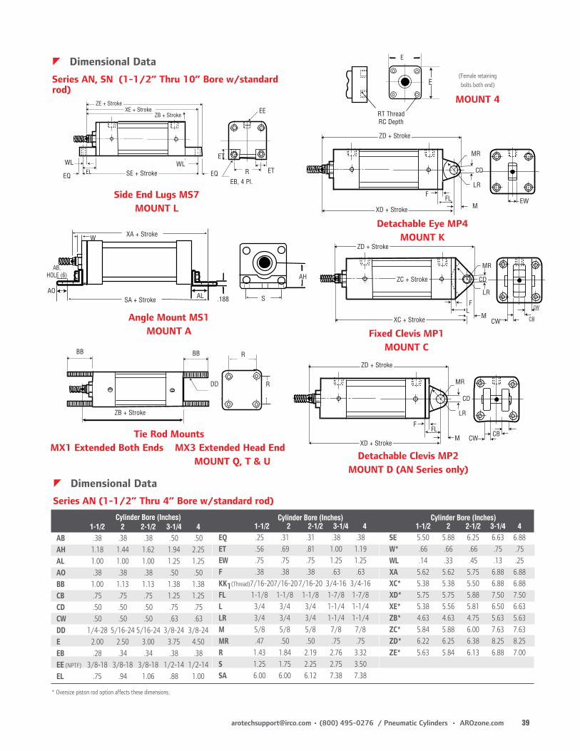
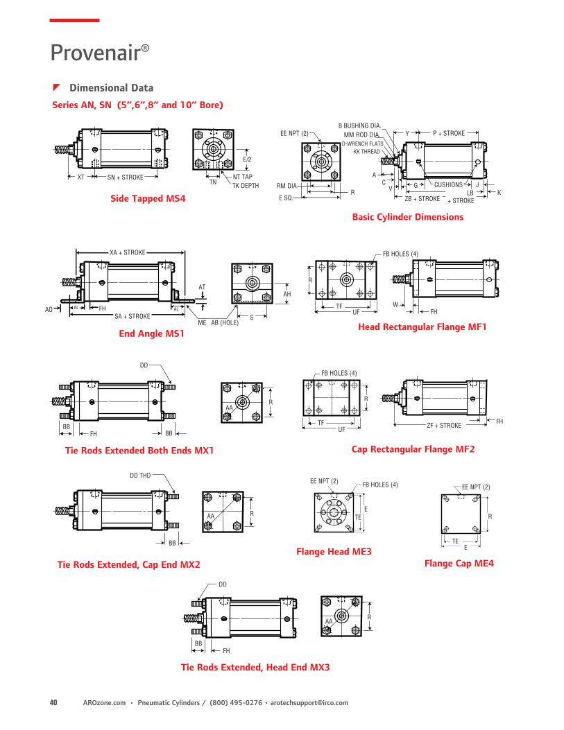
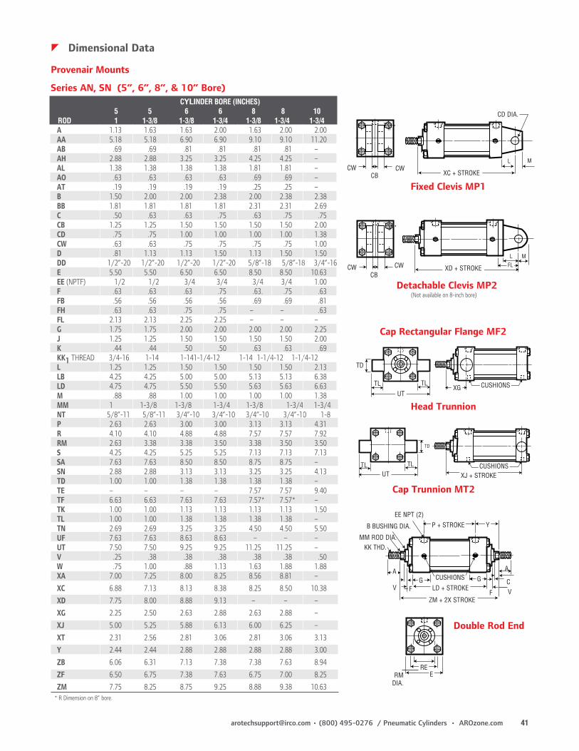
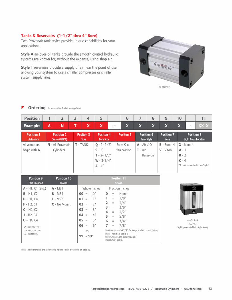
Series AN & SN Provenair® (1-1/2” thru 10” bore)
Provenair Cylinders are NFPA interchangeable square head cylinders designed for rugged use. Available in 1-1/2 to 10-inch bore sizes. They operate on air pressure up to 250 PSI, generating thrusts up to 3,141 pounds. They are available as double-acting, with optional cushions, magnetic pistons and/or with double rod ends. A broad selection of NFPA standard mounts makes them dimensionally interchangeable with other NFPA cylinders..
zFor more information, see pages 31 through 45.
Premair™ Series Square Metric Compact(12mm thru 160mm bore)
Premair Square Metric Compact Cylinders are available in 13 bore sizes, from 12mm thru 160mm. All cylinders come with NPT Ports and inch threads on rod end, and magnetic piston as standard. Mounting through holes are tapped and accept a variety of mounting kits. These cylinders interchange with the leading manufacturers of Square Compact Cylinders.
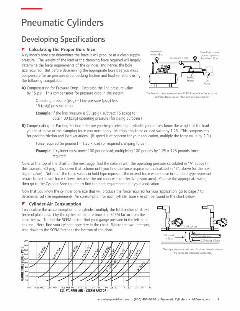
Developing SpecificationszCalculating the Proper Bore SizeA cylinder’s bore size determines the force it will produce at a given supply pressure. The weight of the load or the clamping force required will largely determine the force requirements of the cylinder, and hence, the bore size required. But before determining the appropriate bore size you must compensate for air pressure drop, packing friction and load variations using the following computation:
A) Compensating for Pressure Drop – Decrease the line pressure value by 15 p.s.i. This compensates for pressure drop in the system.
Operating pressure (psig) = Line pressure (psig) less 15 (psig) pressure drop
Example: If the line pressure is 95 (psig), subtract 15 (psig) to obtain 80 (psig) operating pressure (for sizing purposes)
B) Compensating for Packing Friction – Before you begin selecting a cylinder you already know the weight of the load you must move or the clamping force you must apply. Multiply this force or load value by 1.25. This compensates for packing friction and load variations. (If speed is of concern for your application, multiply the force value by 2.0.)
Force required (in pounds) = 1.25 x load (or required clamping force)
Example: If cylinder must move 100 pound load, multiplying 100 pounds by 1.25 = 125 pounds force required.
Now, at the top of the chart on the next page, find the column with the operating pressure calculated in “A” above (in this example, 80 psig). Go down that column until you find the force requirement calculated in “B”, above (or the next higher value). Note that the force values in bold type represent the extend force while those in standard type represent retract force (retract force is lower because the rod reduces the effective piston area). Choose the appropriate value, then go to the Cylinder Bore column to find the bore requirements for your application.
Now that you know the cylinder bore size that will produce the force required for your application, go to page 7 to determine rod size requirements. Air consumption for each cylinder bore size can be found in the chart below.
Downstream pressure because of pressure loss in lines: 80 psipressure loss in lines
Air pressure at source. 95 psi
LoadFriction
Packing Friction
This illustration shows a pressure loss of 15 PSI through the airlines and points out friction factors, both of which must be compensated for.
2-inch cylinder
5/8-inch diameter
227 pounds of force
251 pounds of force
Given equal pressure on both sides of a piston, the surface area on the extend side will provide greater force.
zCylinder Air ConsumptionTo calculate the air consumption of a cylinder, multiply the total inches of stroke (extend plus retract) by the cycles per minute times the SCFM factor from the chart below. To find the SCFM factor, find your gauge pressure in the left hand column. Next, find your cylinder bore size in the chart. Where the two intersect, read down to the SCFM factor at the bottom of the chart.
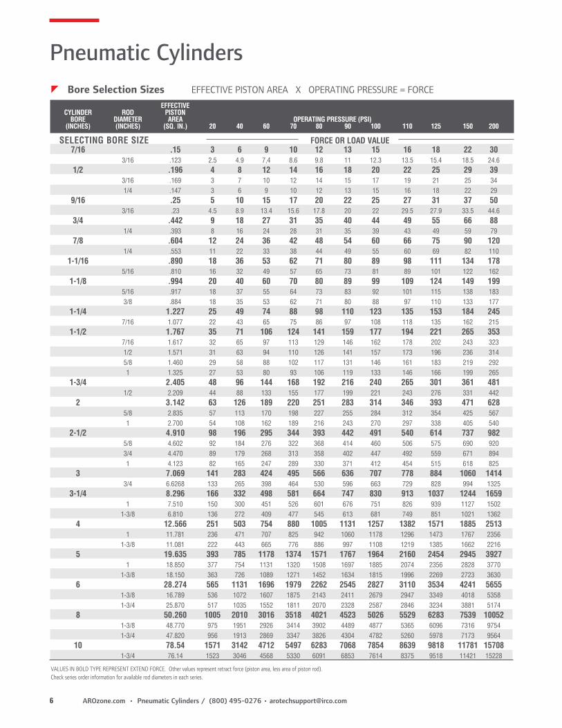
Pneumatic CylinderszBore Selection Sizes EFFECTIVE PISTON AREA X OPERATING PRESSURE = FORCE
SELECTING BORE SIZE FORCE OR LOAD VALUE
VALUES IN BOLD TYPE REPRESENT EXTEND FORCE. Other values represent retract force (piston area, less area of piston rod). Check series order information for available rod diameters in each series.
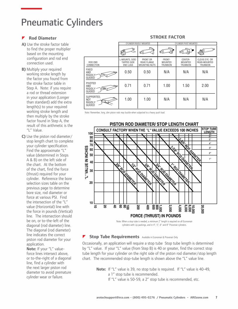
zStop Tube Requirements Available in Economair & Provenair Only
Occasionally, an application will require a stop tube Stop tube length is determined by “L” value. If your “L” value (from Step B) is 40 or greater, find the correct stop tube length for your cylinder on the right side of the piston rod diameter/stop length chart. The recommended stop-tube length is shown above the “L” value line.
Note: If “L” value is 39, no stop tube is required. If “L” value is 40-49, a 1” stop tube is recommended. If “L” value is 50-59, a 2” stop tube is recommended, etc.
Note: When a stop tube is needed, a minimum 2” length is required on all Economair cylinders with Lip packings, and in 4”, 5”, 6” and 8” Provenair cylinders.
STROKE FACTOR
L-MOUNTS, SIDE- FRONT OR FRONT- CENTER- CLEVIS EYE. OR ROD END TAPPED SIDE REAR FLANGE MOUNTED MOUNTED REAR-MOUNTED CONNECTION END LUGS MOUNTING NUTS TRUNNION TRUNNION TRUNNION
FIXEDAND 0.50 0.50 N/A N/A N/ARIGIDLYGUIDED
PIVOTED AND 0.71 0.71 1.00 1.50 2.00RIGIDLYGUIDED
SUPPORTED,NOT 1.00 1.00 N/A N/A N/ARIGIDLY GUIDED
CYLINDER RIGIDLY MOUNTED CYLINDER PIVOT MOUNTED
Note: Remember, long ,slim piston rods may buckle when subjected to a heavy push load.
zRod DiameterA) Use the stroke factor table
to find the proper multiplier based on the mounting configuration and rod end connection used.
B) Multiply your required working stroke length by the factor you found from the stroke factor table in Step A. Note: if you require a rod or thread extension in your application (Longer than standard) add the extra length(s) to your required working stroke length and then multiply by the stroke factor found in Step A, the result of this arithmetic is the “L” Value.
C) Use the piston rod diameter/ stop length chart to complete your cylinder specification. Find the approximate “L” value (determined in Steps A & B) on the left side of the chart. At the bottom of the chart, find the force (thrust) required for your cylinder. Reference the bore selection sizes table on the previous page to determine bore size, rod diameter or force at various PSI. Find the intersection of the “L” value (Horizontal) line with the force in pounds (Vertical) line. The intersection should be on, or to-the-left of the diagonal (rod diameter) line. The diagonal (rod diameter) line indicates the correct piston rod diameter for your application. Note: If your “L” value-force lines intersect above, or to-the-right of a diagonal line, find a cylinder with the next larger piston rod diameter to avoid premature cylinder wear or failure.
Pneumatic CylinderszOptions Additional options required will help determine which cylinder series will be selected:
Stainless steel piston rods are beneficial in corrosive environments. Stainless steel rods are standard on Micro-Air and Silverair Series. Stainless Steel rods are options on Economair and Provenair Series.
Cylinder cushions are designed to reduce the shock experienced at the end of the stroke by reducing piston speed the last fraction of an inch of stroke. Cylinder cushions are available in Economair and Provenair Series, only.
zPacking shape and material affect cylinder performance: • O-Ring packings are good, general purpose packings, but they require more breakaway force than other packing
shapes.
• O-Ring – Low Friction packings provide the effective sealing characteristics of Buna N with the low friction characteristics of PTFE. This design is effective where the cylinder must operate at low pressures.
• U-Cup packings offer low breakaway friction and better sealing characteristics at low pressure than O-Ring packings. U-cups are wear compensating seals; they offer longer wear life than O-rings.
• U-Cup – Self Lube (“Slippery Seals”) packings are ideal in applications where air line lubrication cannot be used. This packing design helps reduce cylinder “chatter” in low pressure applications and it offers the same sealing characteristics as Buna N.
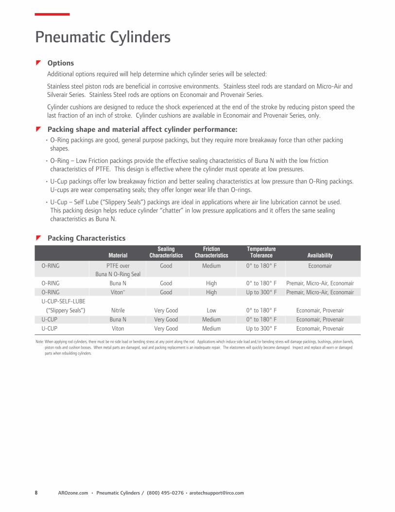
zPacking Characteristics Sealing Friction Temperature Material Characteristics Characteristics Tolerance Availability
O-RING PTFE over Good Medium 0° to 180° F Economair Buna N O-Ring SealO-RING Buna N Good High 0° to 180° F Premair, Micro-Air, EconomairO-RING Viton® Good High Up to 300° F Premair, Micro-Air, EconomairU-CUP-SELF-LUBE (“Slippery Seals”) Nitrile Very Good Low 0° to 180° F Economair, ProvenairU-CUP Buna N Very Good Medium 0° to 180° F Economair, ProvenairU-CUP Viton Very Good Medium Up to 300° F Economair, Provenair
Note: When applying rod cylinders, there must be no side load or bending stress at any point along the rod. Applications which induce side load and/or bending stress will damage packings, bushings, piston barrels, piston rods and cushion bosses. When metal parts are damaged, seal and packing replacement is an inadequate repair. The elastomers will quickly become damaged. Inspect and replace all worn or damaged parts when rebuilding cylinders.
Micro-Air Cylinders are ideal for small part positioning, clamping and ejecting. Also they’re the perfect choice for applications where small bore, medium duty, repairable cylinders are preferred. Prelubed, they’re suitable for operations without externally applied lubrication.
• Micro-Air Cylinders are repairable. Service kits are available to extend the useable life of the cylinder.
• Micro-Air Cylinders operate on air pressure to 200 p.s.i. (14 bar). A tough little cylinder that can handle the pressures!
• Superior performance over a wide temperature range – 0° to 180° F (-18° to 82° C), even to 300° F (149° C) when Viton seals are used (consult factory).
• Micro-Air Cylinders have superior wear characteristics, thanks to the hard coated aluminum tubing I.D. In addition to an internal hardness of 60 Rockwell C, the barrel has an internal finish of 16 microinches or better.
• Micro-Air Cylinders are equipped with Series 303 stainless steel piston rods for corrosion resistance. Also, the ground and polished finish on the rods minimizes friction, providing longer packing life.
• Micro-Air Cylinders provide greater durability than disposable cylinders.
• Double end-mount cylinders can also be used as a pivot mount. Pivot pin included with each cylinder.
zPerformance Specs
Bore Sizes: 3/4” and 1-1/8”
Maximum Output Force: 199 pounds (1-1/8” bore)
Standard Operating 0° to 180°F (-18° to 82°C)Temperature Range:
Viton Seals Models: For high heat applications. Consult factory.
Range of mounting styles and attachable mounts/ accessories to meet nearly any application requirement.
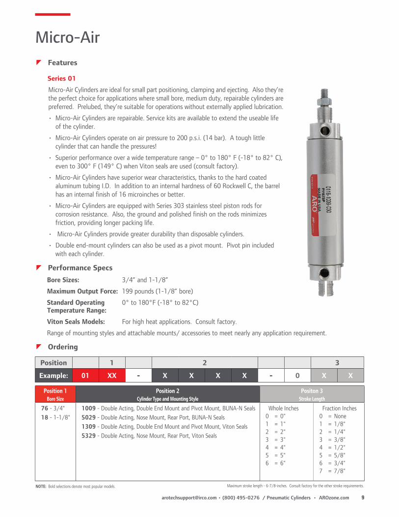
Series 01
NOTE: Bold selections denote most popular models. Maximum stroke length - 6-7/8-inches. Consult factory for the other stroke requirements.
Position 1 2 3
Example: 01 XX - X X X X - 0 X X
Position 1Bore Size
Position 2Cylinder Type and Mounting Style
Positon 3Stroke Length
76 - 3/4"18 - 1-1/8"
1009 - Double Acting, Double End Mount and Pivot Mount, BUNA-N Seals5029 - Double Acting, Nose Mount, Rear Port, BUNA-N Seals1309 - Double Acting, Double End Mount and Pivot Mount, Viton Seals5329 - Double Acting, Nose Mount, Rear Port, Viton Seals
Silverair round cylinders are designed for application in OEM and MRO applications where a disposable, light duty cylinder is preferred. Prelubed, they’re suitable for operations without externally applied lubrication. Constructed of stainless steel and aluminum, they stand up to the attack of corrosive environments.
• Silverair cylinders feature stainless steel (Series 304) barrels. Drawn and polished internal diameters have superior lube-holding characteristics for a low friction surface that gives smooth performance and outstanding cycle life.
• Piston rods are centerless ground and polished Series 303 stainless steel, providing smooth rod movement.
• Lightweight aluminum heads feature full flow ports for maximum air flow and smooth response.
• Piston rod threads are roll formed to provide superior strength and durability.
• U-cup design on piston seals provides continuous cylinder barrel contact, minimizes blow-by and offers longer seal life than O-ring piston seals.
• The oil-permeated bronze rod bushing is precision ball sized for reduced friction and increased cylinder life.
• Return springs on single-acting cylinders are made from a high tensile alloy for exceptional performance and long service life.
• Silverair cylinders are prelubricated, so they’re ideal in applications where external lubrication can’t be supplied.
Series S
zPerformance Specifications
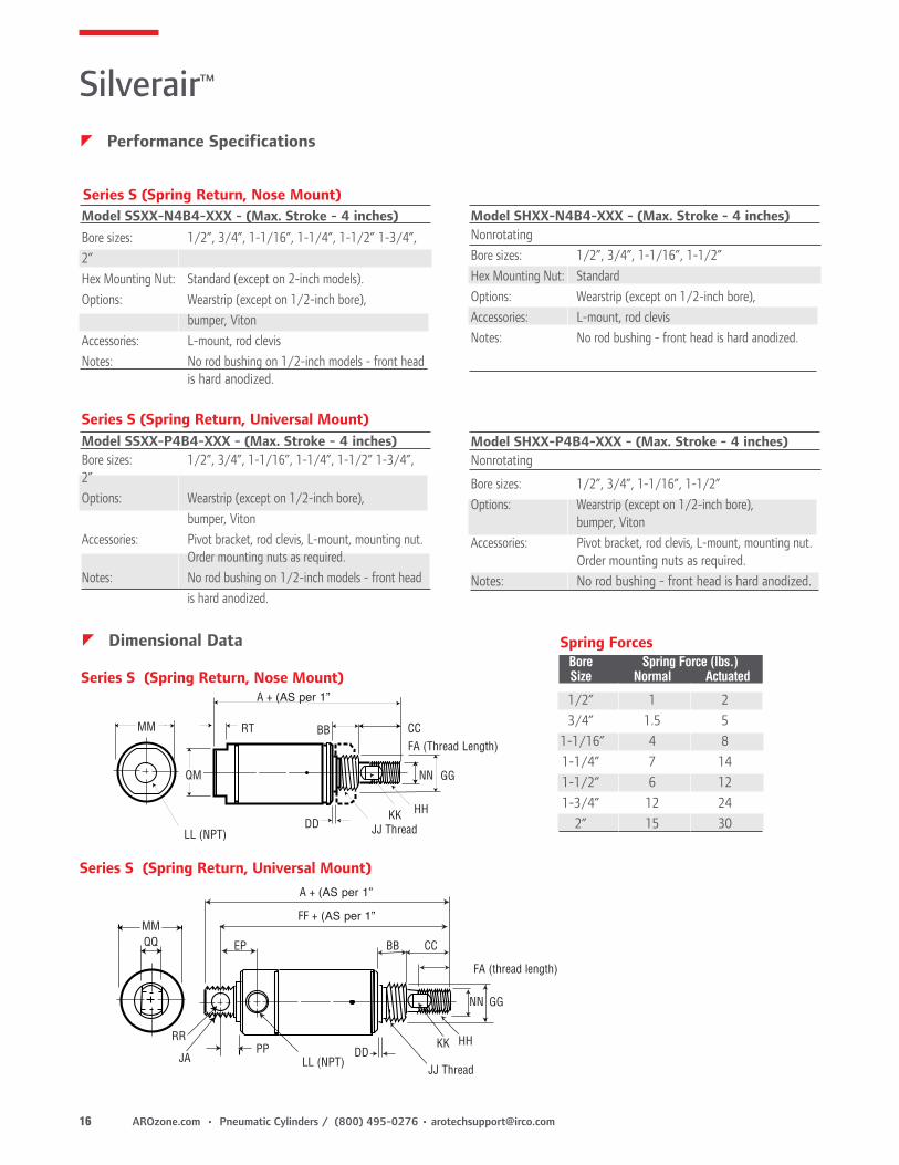
Bore Sizes: 1/2”, 3/4”, 1-1/16”, 1-1/4”, 1-1/2”, 2” & 2-1/2”Air Pressure: to 200 p.s.i. (14 bar)Operating Temperature Range: -40° to 160° F (18° to 82° C)Maximum Output Force: 982 pounds (2-1/2-inch bore cylinder)Viton Seals Models: For high heat applications, consult factoryRange of mounting styles and attachable mounts/accessories covers wide range of application requirements.Magnetic pistons available for use with Hall Effect or Reed Switches.
Note A: Bumpers • Not available with magnetic piston option. • Standard on double rod ends. • Do not affect external dimensions.
Note B: Wearstrip is standard on double-acting nose mount, universal mount and block front mount of 5” or more of stroke. Also on single acting, spring extend cylinders with 3” or more of stroke. Not available on 1/2” bore cylinders. Not available on single acting, hex rod (non-rotating rod)
zOrdering Include dashes. Dashes are significant.
Position 1 2 3 4 5 6 7 8
Example: S X XX - X X X X - XX X
Position 1Series
Position 2Cylinder Type
Positon 3Bore Size
S - Stainless Steel S - Single Acting, Spring Return (Not available on 25 bore size)
D - Double ActingR - Single Acting, Spring Extend
(Not available on 25 bore size)H - Single Acting, Hex Rod (Non-rotating rod)
(Spring return only)Not available on 14, 17,20 or 25 bore sizes)
05 1/2"07 3/4"11 1-1/16"14 1-1/4" (Not available on type SH)15 1-1/2"17 1-3/4" (Not available on type SH)20 2" (Not available on type SH)25 2-1/2" (Not available on type SS, SR or SH)
Position 4Mounting Style
Position 5Magnet/Bumpers (Note A)
Positon 6Packing
Positon 7Wearsrtip (Note B)
B - Block Mount (Available on 05, 07, 11 and 15 bore size only) (Not available on type SH)
D - Double Rod End (Double Acting Only)
N - Nose Mount P - Universal Mount
(Pivot or Double End)Silverair attachable mounts must be ordered separately.See page 14
4 - No Bumpers, no magnetB - BumpersM - Magnetic Piston
(Not available in 1/2” bore or for single-acting cylinders)
* FOR DOUBLE END MOUNTING OF SINGLE-ACTING CYLINDERS, ORDER THE FOLLOWING:1/2-inch bore One 118108-5 L-Mount and one 118109-5 Nut for rear mounting thread. One 118108-50
L-Mount and one 118109-50 Nut for front mounting thread.3/4-inch bore Two 118108-7 L-Mounts, one 118109-7 Nut for rear mounting thread and one 118109-11 Nut
for front mounting thread.
NOTE: Silverair accessories are bright zinc plated steel.
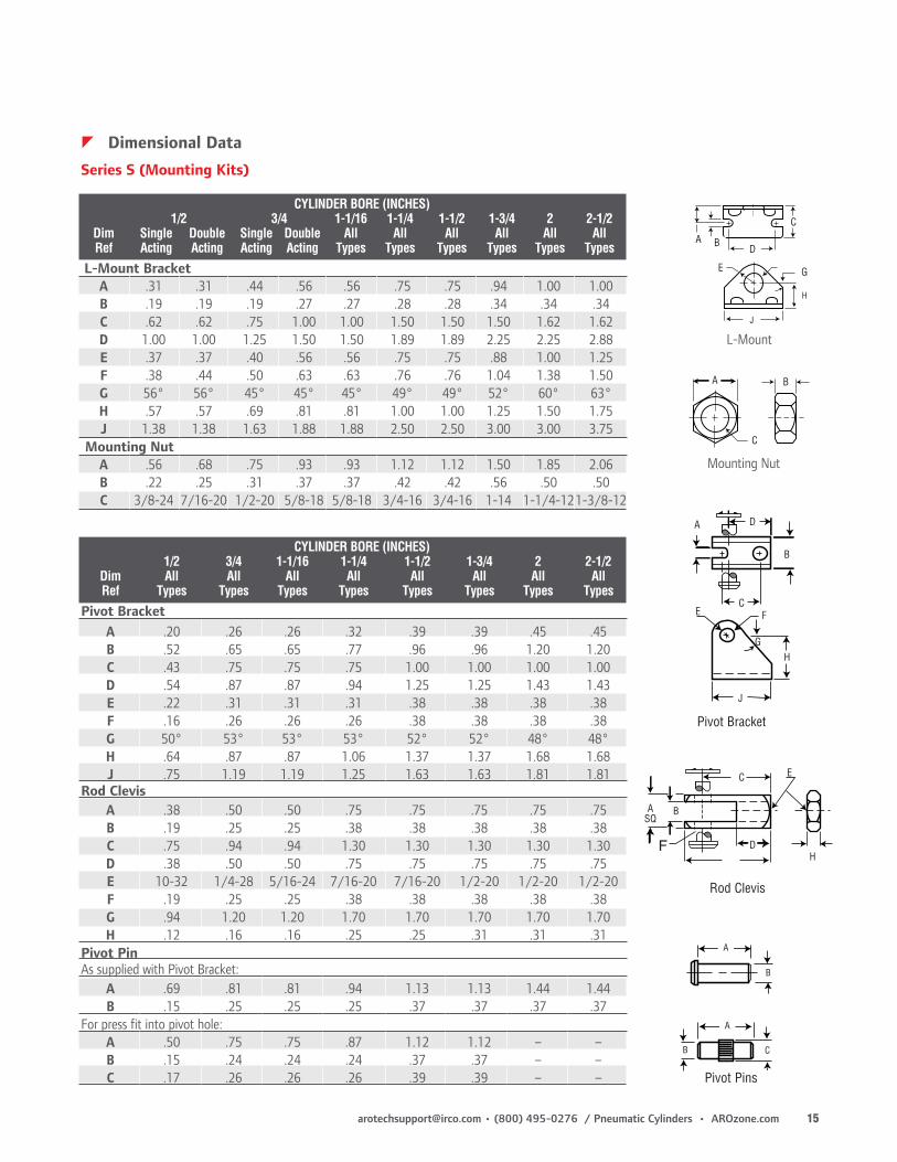
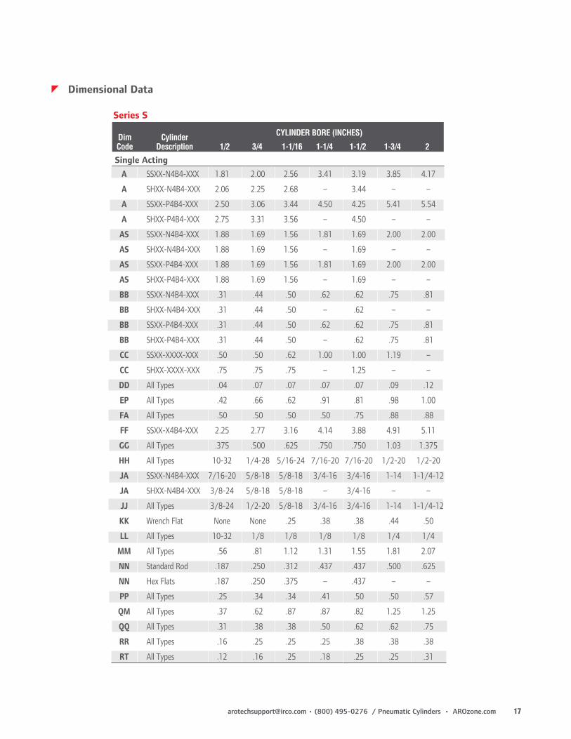
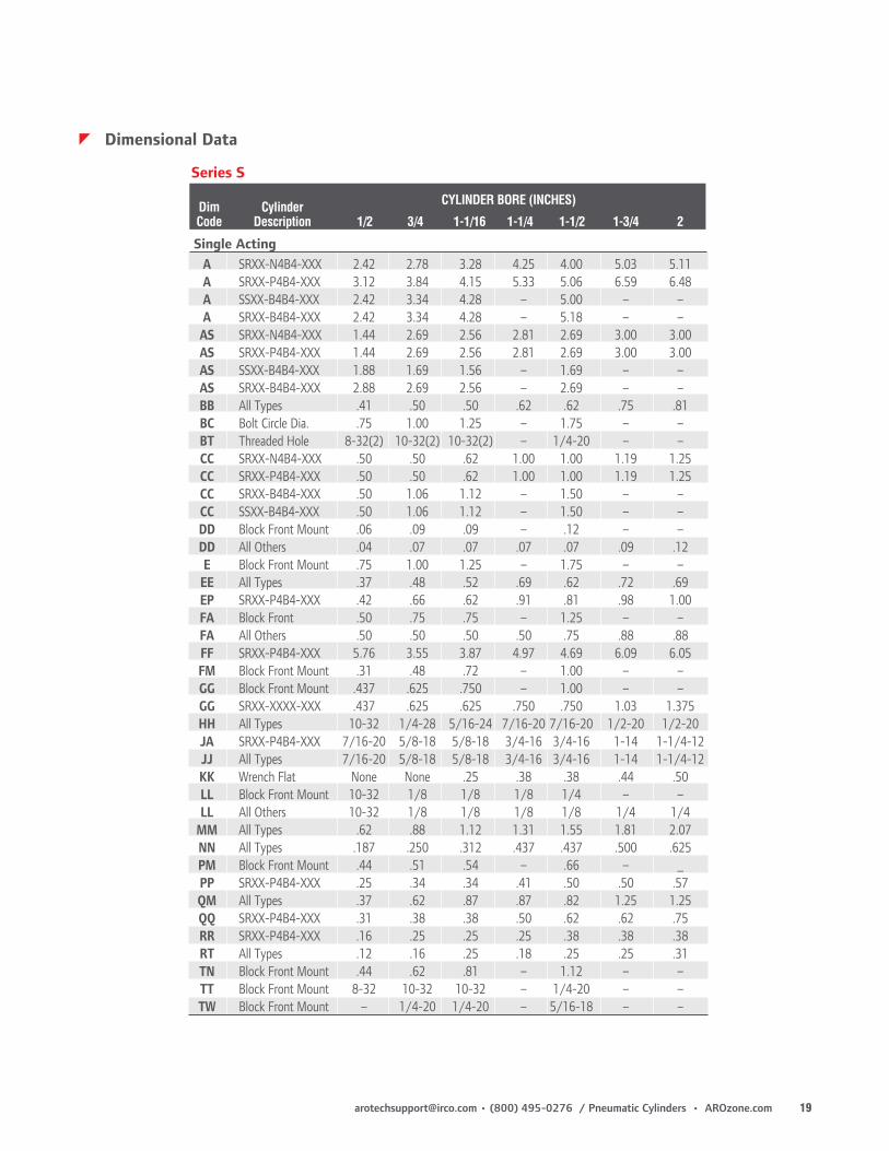
CYLINDER BORE (INCHES) 1/2 3/4 1-1/16 1-1/4 1-1/2 1-3/4 2 2-1/2 Dim Single Double Single Double All All All All All All Ref Acting Acting Acting Acting Types Types Types Types Types Types
CYLINDER BORE (INCHES) 1/2 3/4 1-1/16 1-1/4 1-1/2 1-3/4 2 2-1/2 Dim All All All All All All All All Ref Types Types Types Types Types Types Types Types
Pivot Bracket A .20 .26 .26 .32 .39 .39 .45 .45 B .52 .65 .65 .77 .96 .96 1.20 1.20 C .43 .75 .75 .75 1.00 1.00 1.00 1.00 D .54 .87 .87 .94 1.25 1.25 1.43 1.43 E .22 .31 .31 .31 .38 .38 .38 .38 F .16 .26 .26 .26 .38 .38 .38 .38 G 50° 53° 53° 53° 52° 52° 48° 48° H .64 .87 .87 1.06 1.37 1.37 1.68 1.68 J .75 1.19 1.19 1.25 1.63 1.63 1.81 1.81Rod Clevis A .38 .50 .50 .75 .75 .75 .75 .75 B .19 .25 .25 .38 .38 .38 .38 .38 C .75 .94 .94 1.30 1.30 1.30 1.30 1.30 D .38 .50 .50 .75 .75 .75 .75 .75 E 10-32 1/4-28 5/16-24 7/16-20 7/16-20 1/2-20 1/2-20 1/2-20 F .19 .25 .25 .38 .38 .38 .38 .38 G .94 1.20 1.20 1.70 1.70 1.70 1.70 1.70 H .12 .16 .16 .25 .25 .31 .31 .31Pivot PinAs supplied with Pivot Bracket: A .69 .81 .81 .94 1.13 1.13 1.44 1.44 B .15 .25 .25 .25 .37 .37 .37 .37For press fit into pivot hole: A .50 .75 .75 .87 1.12 1.12 – – B .15 .24 .24 .24 .37 .37 – – C .17 .26 .26 .26 .39 .39 – –
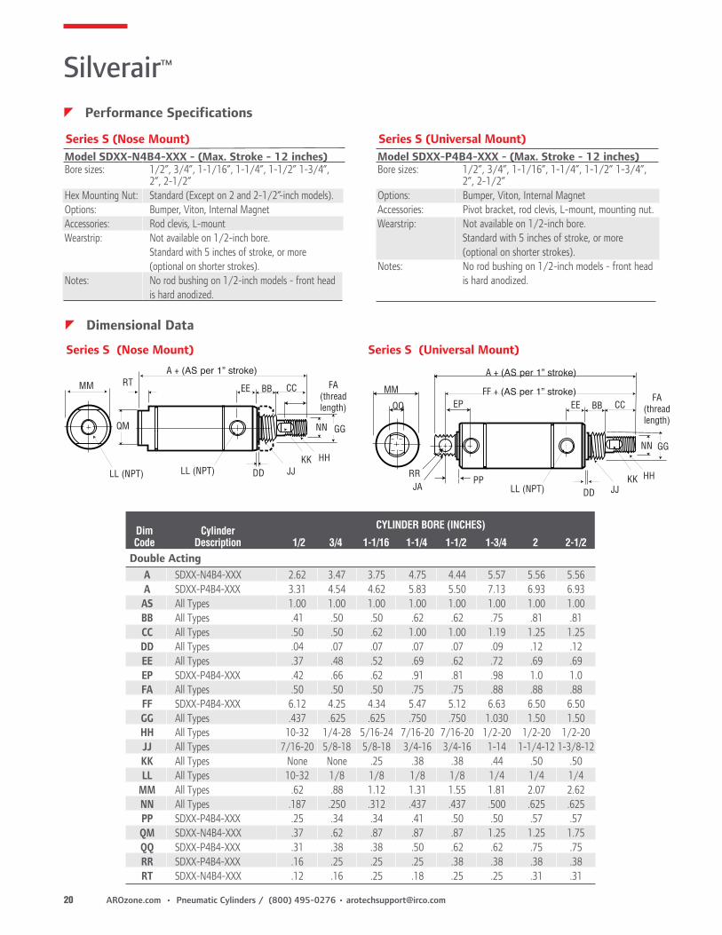
Model SSXX-P4B4-XXX - (Max. Stroke - 4 inches)Bore sizes: 1/2”, 3/4”, 1-1/16”, 1-1/4”, 1-1/2” 1-3/4”, 2”Options: Wearstrip (except on 1/2-inch bore), bumper, VitonAccessories: Pivot bracket, rod clevis, L-mount, mounting nut. Order mounting nuts as required.Notes: No rod bushing on 1/2-inch models - front head is hard anodized.
zPerformance Specifications
zDimensional Data
Model SSXX-N4B4-XXX - (Max. Stroke - 4 inches)Bore sizes: 1/2”, 3/4”, 1-1/16”, 1-1/4”, 1-1/2” 1-3/4”, 2”Hex Mounting Nut: Standard (except on 2-inch models).Options: Wearstrip (except on 1/2-inch bore), bumper, VitonAccessories: L-mount, rod clevisNotes: No rod bushing on 1/2-inch models - front head is hard anodized.
MM
GGNN
KK HH
JJ ThreadDD
CCRT BB
QM
LL (NPT)
A + (AS per 1”
FA (Thread Length)
Series S (Spring Return, Nose Mount)
Series S (Spring Return, Universal Mount)
Series S (Spring Return, Nose Mount)
Series S (Spring Return, Universal Mount)
MM
HHKK
NN GG
DDPP
CCBB
LL (NPT)JJ Thread
EPQQ
RR
JA
A + (AS per 1”
FF + (AS per 1”
FA (thread length)
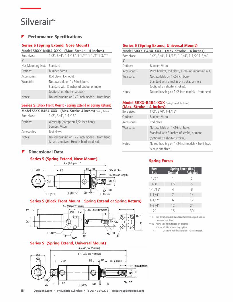
Spring Forces Bore Spring Force (lbs.) Size Normal Actuated
Model SHXX-P4B4-XXX - (Max. Stroke - 4 inches)Nonrotating
Bore sizes: 1/2”, 3/4”, 1-1/16”, 1-1/2”Options: Wearstrip (except on 1/2-inch bore), bumper, VitonAccessories: Pivot bracket, rod clevis, L-mount, mounting nut. Order mounting nuts as required.Notes: No rod bushing - front head is hard anodized.
Model SHXX-N4B4-XXX - (Max. Stroke - 4 inches)NonrotatingBore sizes: 1/2”, 3/4”, 1-1/16”, 1-1/2”Hex Mounting Nut: StandardOptions: Wearstrip (except on 1/2-inch bore),Accessories: L-mount, rod clevisNotes: No rod bushing - front head is hard anodized.
*TT - Two thru holes drilled and counterbored on port side for cap screw size listed.
** TW - Above thru holes tapped on opposite side for additional mounting option.
† - Mounting hole locations for 1/2-inch models.
Model SSXX-B4B4-XXX - (Max. Stroke-4 inches) (Spring Return)
Bore sizes: 1/2”, 3/4”, 1-1/16”
Options: Wearstrip (except on 1/2-inch bore), bumper, VitonAccessories: Rod clevisNotes: No rod bushing on 1/2-inch models - front head is hard anodized. Head is hard anodized.
zPerformance Specifications
zDimensional Data
Model SRXX-N4B4-XXX - (Max. Stroke - 4 inches)Bore sizes: 1/2”, 3/4”, 1-1/16”, 1-1/4”, 1-1/2” 1-3/4”, 2”Hex Mounting Nut: StandardOptions: Bumper, VitonAccessories: Rod clevis, L-mountWearstrip: Not available on 1/2-inch bore. Standard with 3 inches of stroke, or more (optional on shorter strokes).Notes: No rod bushing on 1/2-inch models - front head
(Max. Stroke - 4 inches)Bore sizes: 1/2”, 3/4”, 1-1/16”Options: Bumper, VitonAccessories: Rod clevisWearstrip: Not available on 1/2-inch bore. Standard with 3 inches of stroke, or more (optional on shorter strokes).Notes: No rod bushing on 1/2-inch models - front head is hard anodized.
Model SRXX-P4B4-XXX - (Max. Stroke - 4 inches)Bore sizes: 1/2”, 3/4”, 1-1/16”, 1-1/4”, 1-1/2” 1-3/4”, 2”Options: Bumper, VitonAccessories: Pivot bracket, rod clevis, L-mount, mounting nut.Wearstrip: Not available on 1/2-inch bore. Standard with 3 inches of stroke, or more (optional on shorter strokes).Notes: No rod bushing on 1/2-inch models - front head
Series S (Spring Extend, Universal Mount)
Series S (Block Front Mount - Spring Extend or Spring Return)
Series S (Spring Extend, Universal Mount)
Series S (Spring Extend, Nose Mount)
Silverair™
Series S (Block Front Mount - Spring Extend or Spring Return)
Model SDXX-N4B4-XXX - (Max. Stroke - 12 inches)Bore sizes: 1/2”, 3/4”, 1-1/16”, 1-1/4”, 1-1/2” 1-3/4”, 2”, 2-1/2”Hex Mounting Nut: Standard (Except on 2 and 2-1/2”-inch models).Options: Bumper, Viton, Internal MagnetAccessories: Rod clevis, L-mountWearstrip: Not available on 1/2-inch bore. Standard with 5 inches of stroke, or more (optional on shorter strokes).Notes: No rod bushing on 1/2-inch models - front head is hard anodized.
Series S (Nose Mount)Model SDXX-P4B4-XXX - (Max. Stroke - 12 inches)Bore sizes: 1/2”, 3/4”, 1-1/16”, 1-1/4”, 1-1/2” 1-3/4”, 2”, 2-1/2”Options: Bumper, Viton, Internal MagnetAccessories: Pivot bracket, rod clevis, L-mount, mounting nut.Wearstrip: Not available on 1/2-inch bore. Standard with 5 inches of stroke, or more (optional on shorter strokes).Notes: No rod bushing on 1/2-inch models - front head is hard anodized.
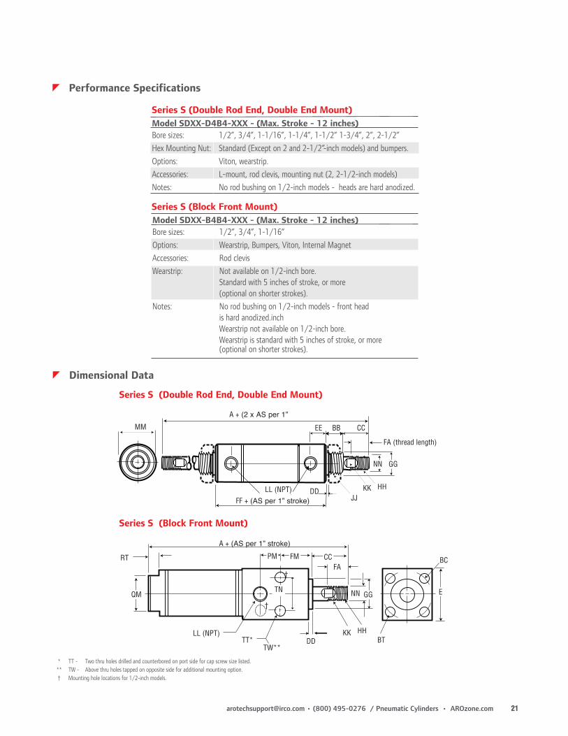
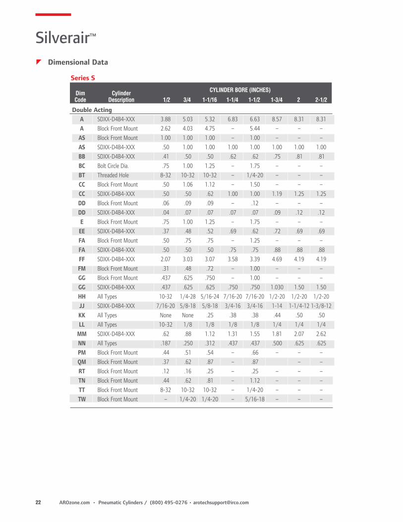
Model SDXX-D4B4-XXX - (Max. Stroke - 12 inches)Bore sizes: 1/2”, 3/4”, 1-1/16”, 1-1/4”, 1-1/2” 1-3/4”, 2”, 2-1/2”Hex Mounting Nut: Standard (Except on 2 and 2-1/2”-inch models) and bumpers.Options: Viton, wearstrip.Accessories: L-mount, rod clevis, mounting nut (2, 2-1/2-inch models)Notes: No rod bushing on 1/2-inch models - heads are hard anodized.
Series S (Double Rod End, Double End Mount)
Model SDXX-B4B4-XXX - (Max. Stroke - 12 inches)Bore sizes: 1/2”, 3/4”, 1-1/16”Options: Wearstrip, Bumpers, Viton, Internal MagnetAccessories: Rod clevisWearstrip: Not available on 1/2-inch bore. Standard with 5 inches of stroke, or more (optional on shorter strokes).Notes: No rod bushing on 1/2-inch models - front head is hard anodized.inch Wearstrip not available on 1/2-inch bore. Wearstrip is standard with 5 inches of stroke, or more (optional on shorter strokes).
Series S (Block Front Mount)
MM EE
NN GG
DDJJ
KK HH
FA (thread length)
BB CC
A + (2 x AS per 1”
FF + (AS per 1” stroke)LL (NPT)
Series S (Double Rod End, Double End Mount)
zDimensional Data
RT
LL (NPT)DD
KK
E
BT
BC
HH
PM FM
NN GG
CCFA
TT*TW**
TN
†
†QM
A + (AS per 1” stroke)
Series S (Block Front Mount)
* TT - Two thru holes drilled and counterbored on port side for cap screw size listed. ** TW - Above thru holes tapped on opposite side for additional mounting option. † Mounting hole locations for 1/2-inch models.
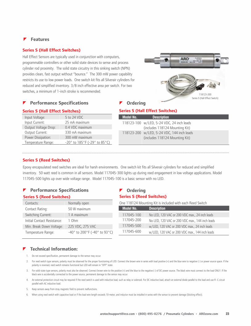
Hall Effect Sensors are typically used in conjunction with computers, programmable controllers or other solid state devices to sense and process cylinder rod proximity. The solid state circuitry in this sinking switch (NPN) provides clean, fast output without “bounce.” The 300 mW power capability restricts its use to low power loads. One switch kit fits all Silverair cylinders for reduced and simplified inventory. 3/8 inch effective area per switch. For two switches, a minimum of 1-inch stroke is recommended.
Series S (Hall Effect Switches)
Input Voltage: 5 to 24 VDC Input Current: 25 mA maximum Output Voltage Drop: 0.4 VDC maximum Output Current: 330 mA maximum Power Dissipation: 300 mW maximum Temperature Range: -20° to 185°F (-29° to 85°C)
zPerformance Specifications
Series S (Hall Effect Switches)
zOrdering
Series S (Hall Effect Switches) Model No. Description
zTechnical Information:1. Do not exceed specification, permanent damage to the sensor may occur.
2. For reed switch type sensors, polarity must be observed for the proper functioning of LED. Connect the brown wire in series with load positive (+) and the blue wire to negative (-) or power source space. If the polarity is reversed, reed switch remains functional but LED will remain in “OFF” state.
3. For solid-state type sensors, polarity must also be observed. Connect brown wire to the positive (+) and the blue to the negative (-) of DC power source. The black wire must connect to the load ONLY. If the black wire is accidentally connected to the power source, permanent damage to the sensor may occur.
4. An external protection circuit may be required if the reed switch is used with inductive load, such as relay or solenoid. For DC inductive load, attach an external diode parallel to the load and use R -C circuit parallel with AC inductive load.
5. Keep sensors away from stray magnetic field to prevent malfunctions.
6. When using reed switch with capacitive load or if the lead wire length exceeds 10-meter, and inductor must be installed in series with the sensor to prevent damage (Sticking effect).
Epoxy encapsulated reed switches are ideal for harsh environments. One switch kit fits all Silverair cylinders for reduced and simplified inventory. 50 watt reed is common in all sensors. Model 117045-300 lights up during reed engagement in low voltage applications. Model 117045-500 lights up over wide voltage range. Model 117045-100 is a basic sensor with no LED.
Series S (Reed Switches)
zPerformance Specifications
Contacts: Normally open Contact Rating: 50 W maximum Switching Current: 1 A maximum Initial Contact Resistance: 1 Ohm Min. Break Down Voltage: 225 VDC, 275 VAC Temperature Range: -40° to 200°F (-40° to 93°C)
Series S (Reed Switches)zOrderingSeries S (Reed Switches)
Model No. Description
117045-100 No LED, 120 VAC or 200 VDC max., 24 inch leads 117045-200 No LED, 120 VAC or 200 VDC max., 144 inch leads 117045-500 w/LED, 120 VAC or 200 VDC max., 24 inch leads 117045-600 w/LED, 120 VAC or 200 VDC max., 144 inch leads
One 118124 Mounting Kit is included with each Reed Switch
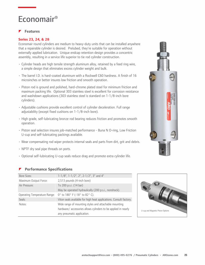
Series 23, 24, & 28 Economair round cylinders are medium to heavy-duty units that can be installed anywhere that a repairable cylinder is desired. Prelubed, they’re suitable for operation without externally applied lubrication. Unique endcap retention design provides a concentric assembly, resulting in a service life superior to tie rod cylinder construction.
• Cylinder heads are high tensile strength aluminum alloy, retained by a feed ring wire, a simple design that eliminates excess cylinder weight and bulk.
• The barrel I.D. is hard-coated aluminum with a Rockwell C60 hardness. A finish of 16 microinches or better insures low friction and smooth operation.
• Piston rod is ground and polished, hard-chrome plated steel for minimum friction and maximum packing life. Optional 303 stainless steel is excellent for corrosion resistance and washdown applications (303 stainless steel is standard on 1-1/8-inch bore cylinders).
• Adjustable cushions provide excellent control of cylinder deceleration. Full range adjustability (except fixed cushions on 1-1/8-inch bore).
• High grade, self-lubricating bronze rod bearing reduces friction and promotes smooth operation.
• Piston seal selection insures job-matched performance - Buna N O-ring, Low Friction U-cup and self-lubricating packings available.
• Wear compensating rod wiper protects internal seals and parts from dirt, grit and debris.
• NPTF dry seal pipe threads on ports.
• Optional self-lubricating U-cup seals reduce drag and promote extra cylinder life.
U-cup and Magnetic Piston Options
zPerformance Specifications
Bore Sizes: 1-1/8”, 1-1/2”, 2”, 2-1/2”, 3” and 4” Maximum Output Force: 2,513 pounds (4-inch bore) Air Pressure: To 200 p.s.i. (1 4 bar) May be operated hydraulically (200 p.s.i., nonshock). Operating Temperature Range: 0° to 180° F (-18° to 82° C). Seals: Viton seals available for high heat applications. Consult factory. Notes: Wide range of mounting styles and attachable mounting
hardware/ accessories allows cylinders to be applied in nearly any pneumatic application.
Note: Order cylinder, rod clevis and clevis bracket separately. Every Economair Cylinder includes rod nut. Trunnion Mount does not include pillow block.
Technical Information:1. Do not exceed specification, permanent damage to the sensor may occur.
2. For reed switch type sensors, polarity must be observed for the proper functioning of LED. Connect the brown wire in series with load positive (+) and the blue wire to negative (-) or power source space. If the polarity is reversed, reed switch remains functional but LED will remain in “OFF” state.
3. For solid-state type sensors, polarity must also be observed. Connect brown wire to the positive (+) and the blue to the negative (-) of DC power source. The black wire must connect to the load ONLY. If the black wire is accidentally connected to the power source, permanent damage to the sensor may occur.
4. An external protection circuit may be required if the reed switch is used with inductive load, such as relay or solenoid. For DC inductive load, attach an external diode parallel to the load and use R -C circuit parallel with AC inductive load.
5. Keep sensors away from stray magnetic field to prevent malfunctions.
6. When using reed switch with capacitive load or if the lead wire length exceeds 10-meter, and inductor must be installed in series with the sensor to prevent damage (Sticking effect).
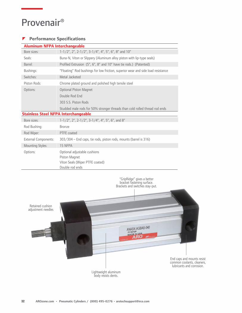
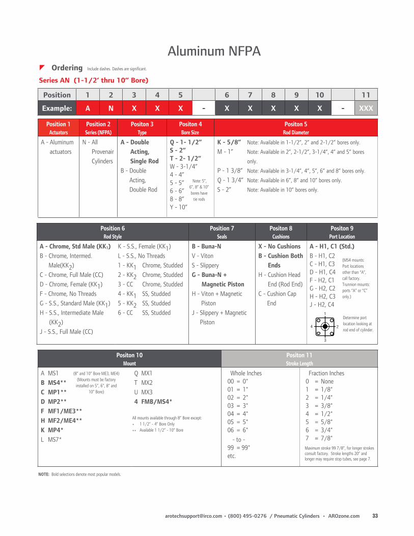
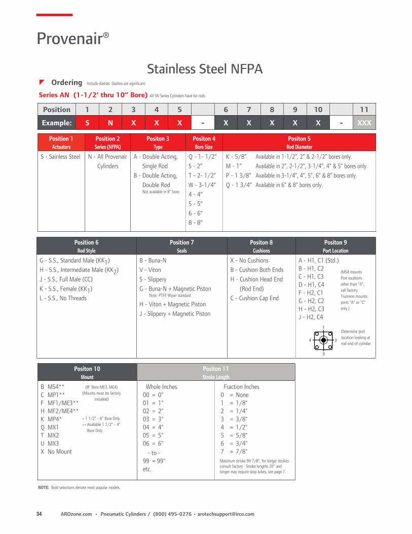
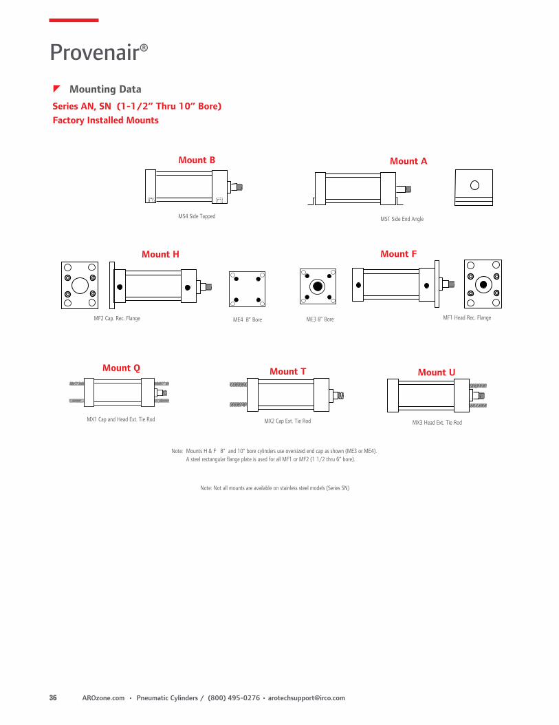
• Tie bolt construction eliminates rod binding and tie rod torque problems. (Series AN up to 4” bore)• Series SN all stainless steel cylinders are corrosion resistant and have tie rods.• Rugged thick walled tubes resist denting.• NFPA repairable and interchangeable.• 15 NFPA mounting styles.• Factory lubricated grease that won’t wash out.• Optional oversized rods available to provide extra column strength. (Series AN and SN)• Operates on air pressure up to 250 p.s.i.• Output forces up to 19,635 lbs. (10” bore at 250 p.s.i.).• Std. operating temp: 0° to 185°(F), -18° to 82° (C).• Rotated ports are optional.• Viton seals for high heat applications (up to 300° F, 149° C)
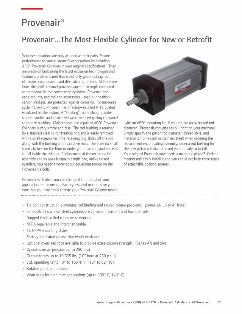
Your best creations are only as good as their parts. Ensure performance to your customer’s expectations by including ARO® Provenair Cylinders in your original specifications. They are precision built using the latest extrusion technologies and feature a profiled barrel that is not only good looking, but eliminates cumbersome and dirt-catching tie rods. At the same time, the profiled barrel provides superior strength compared to traditional tie rod constructed cylinders. Provenair end caps, mounts, and rod end accessories - even our position sensor brackets, are protected against corrosion. To maximize cycle life, every Provenair has a factory-installed PTFE coated wearband on the piston. A “Floating” rod bushing provides smooth strokes and maximized wear; reduced galling compared to bronze bushings. Maintenance and repair of ARO® Provenair Cylinders is very simple and fast. The rod bushing is retained by a stainless steel spiro retaining ring and is easily removed with a small screwdriver. The retaining ring slides off the rod along with the bushing and its captive seals. There are no small screws to lose on the floor or under your machine, and no seals to fall inside the cylinder. Replacement of the reciprocating assembly and its seals is equally simple and, unlike tie rod cylinders, you needn’t worry about equalizing torque on the Provenair tie bolts!
Provenair is flexible, you can change it to fit most of your application requirements. Factory installed mounts save you time, but you may easily change your Provenair Cylinder mount
with an ARO® mounting kit. If you require an oversized rod diameter, Provenair converts easily - right on your machine! Simply specify the piston rod diameter, thread style, and material (chrome steel or stainless steel) when ordering the replacement reciprocating assembly; order a rod bushing for the new piston rod diameter and you’re ready to install. Your original Provenair now needs a magnetic piston? Order a magnet and easily install it and you can select from three types of attachable position sensors.
Provenair®...The Most Flexible Cylinder for New or Retrofit
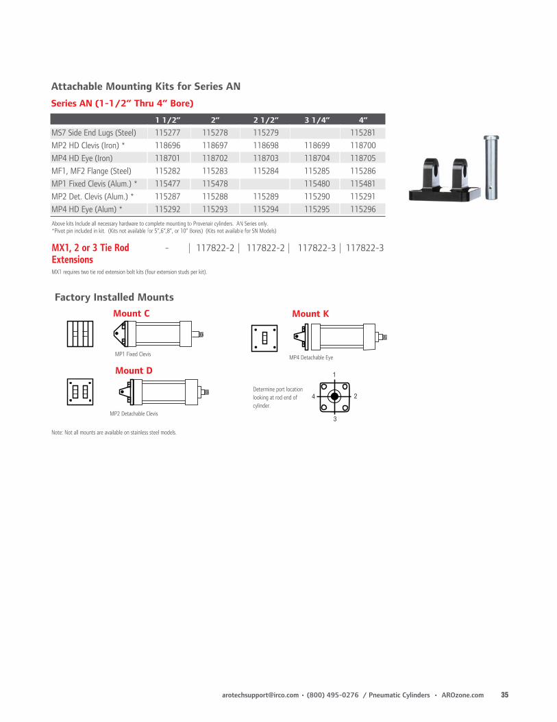
Note: Not all mounts are available on stainless steel models.
Mount K
MP4 Detachable Eye
MP2 Detachable Clevis
MP1 Fixed Clevis
Mount C
Mount D
4
3
2
1
Determine port location looking at rod end of cylinder.
Above kits Include all necessary hardware to complete mounting to Provenair cylinders. AN Series only. *Pivot pin included in kit. (Kits not available for 5”,6”,8”, or 10” Bores) (Kits not available for SN Models)
MX1, 2 or 3 Tie Rod - 117822-2 117822-2 117822-3 117822-3ExtensionsMX1 requires two tie rod extension bolt kits (four extension studs per kit).
MX3 Head Ext. Tie RodMX1 Cap and Head Ext. Tie Rod
MS1 Side End Angle
MX2 Cap Ext. Tie Rod
Mount B
MS4 Side Tapped
Note: Not all mounts are available on stainless steel models (Series SN)
Note: Mounts H & F 8” and 10” bore cylinders use oversized end cap as shown (ME3 or ME4). A steel rectangular flange plate is used for all MF1 or MF2 (1 1/2 thru 6” bore).
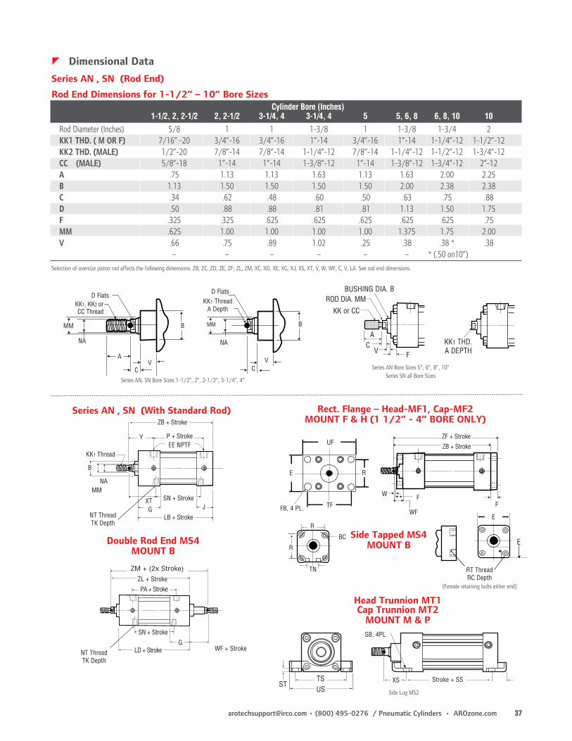
Selection of oversize piston rod affects the following dimensions: ZB, ZC, ZD, ZE, ZF, ZL, ZM, XC, XD, XE, XG, XJ, XS, XT, V, W, WF, C, V, LA. See rod end dimensions.
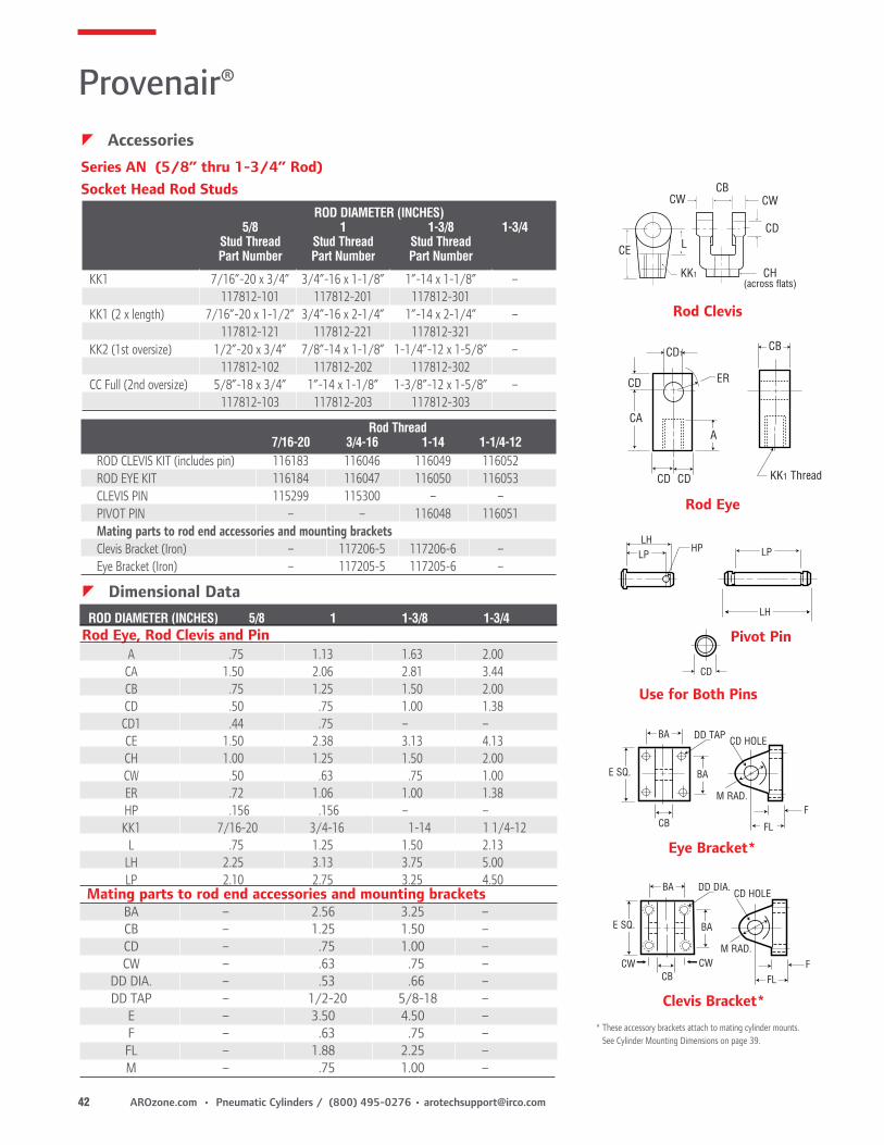
Series AN (5/8” thru 1-3/4” Rod)Socket Head Rod Studs
Use for Both Pins
Eye Bracket*
BA
F
FL
M RAD.
CD HOLE
CB
BA
DD TAP
E SQ.
Clevis Bracket*
CW CW
BA
FFL
M RAD.
CD HOLE
CB
BA
DD DIA.
E SQ.
CD
Pivot Pin
LP LP
LH
HPLH
* These accessory brackets attach to mating cylinder mounts. See Cylinder Mounting Dimensions on page 39.
CA
CD
Rod Clevis
CE
KK1
CD
CWCWCB
CH(across flats)
L
KK1 Thread
CB
A
ER
CD1
CD CD
Rod Eye
ROD DIAMETER (INCHES) 5/8 1 1-3/8 1-3/4 Stud Thread Stud Thread Stud Thread Part Number Part Number Part Number
KK1 7/16”-20 x 3/4” 3/4”-16 x 1-1/8” 1”-14 x 1-1/8” – 117812-101 117812-201 117812-301KK1 (2 x length) 7/16”-20 x 1-1/2” 3/4”-16 x 2-1/4” 1”-14 x 2-1/4” – 117812-121 117812-221 117812-321KK2 (1st oversize) 1/2”-20 x 3/4” 7/8”-14 x 1-1/8” 1-1/4”-12 x 1-5/8” – 117812-102 117812-202 117812-302CC Full (2nd oversize) 5/8”-18 x 3/4” 1”-14 x 1-1/8” 1-3/8”-12 x 1-5/8” – 117812-103 117812-203 117812-303
zDimensional Data ROD DIAMETER (INCHES) 5/8 1 1-3/8 1-3/4Rod Eye, Rod Clevis and Pin A .75 1.13 1.63 2.00 CA 1.50 2.06 2.81 3.44 CB .75 1.25 1.50 2.00 CD .50 .75 1.00 1.38 CD1 .44 .75 – – CE 1.50 2.38 3.13 4.13 CH 1.00 1.25 1.50 2.00 CW .50 .63 .75 1.00 ER .72 1.06 1.00 1.38 HP .156 .156 – – KK1 7/16-20 3/4-16 1-14 1 1/4-12 L .75 1.25 1.50 2.13 LH 2.25 3.13 3.75 5.00 LP 2.10 2.75 3.25 4.50Mating parts to rod end accessories and mounting brackets
BA – 2.56 3.25 – CB – 1.25 1.50 – CD – .75 1.00 – CW – .63 .75 – DD DIA. – .53 .66 – DD TAP – 1/2-20 5/8-18 – E – 3.50 4.50 – F – .63 .75 – FL – 1.88 2.25 – M – .75 1.00 –
Rod Thread 7/16-20 3/4-16 1-14 1-1/4-12ROD CLEVIS KIT (includes pin) 116183 116046 116049 116052ROD EYE KIT 116184 116047 116050 116053CLEVIS PIN 115299 115300 – –PIVOT PIN – – 116048 116051Mating parts to rod end accessories and mounting bracketsClevis Bracket (Iron) – 117206-5 117206-6 –Eye Bracket (Iron) – 117205-5 117205-6 –
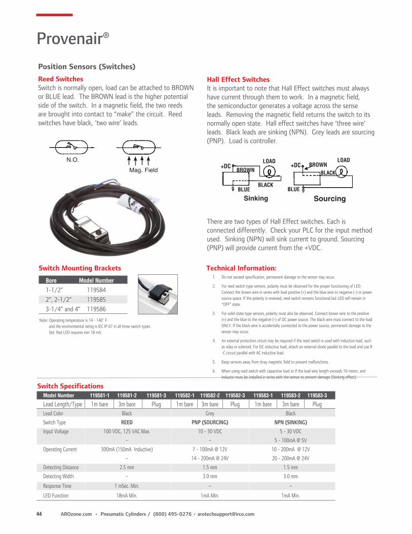
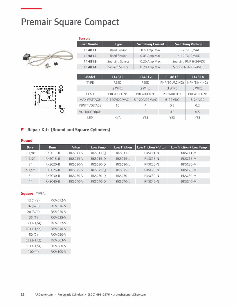
Position Sensors (Switches)Reed SwitchesSwitch is normally open, load can be attached to BROWN or BLUE lead. The BROWN lead is the higher potential side of the switch. In a magnetic field, the two reeds are brought into contact to “make” the circuit. Reed switches have black, ‘two wire’ leads.
Sinking Sourcing
+DC +DCBROWN
BROWN
BLACK
BLACK
LOADLOAD
BLUE BLUE
N.O.Mag. Field
Note: Operating temperature is 14 - 140˚ F and the environmental rating is IEC IP 67 in all three switch types. Std. Red LED requires min 18 mA.
Hall Effect SwitchesIt is important to note that Hall Effect switches must always have current through them to work. In a magnetic field, the semiconductor generates a voltage across the sense leads. Removing the magnetic field returns the switch to its normally open state. Hall effect switches have ‘three wire’ leads. Black leads are sinking (NPN). Grey leads are sourcing (PNP). Load is controller.
There are two types of Hall Effect switches. Each is connected differently. Check your PLC for the input method used. Sinking (NPN) will sink current to ground. Sourcing (PNP) will provide current from the +VDC.
Switch Mounting Brackets
Bore Model Number
1-1/2” 1195842”, 2-1/2” 1195853-1/4” and 4” 119586
Technical Information:1. Do not exceed specification, permanent damage to the sensor may occur.
2. For reed switch type sensors, polarity must be observed for the proper functioning of LED. Connect the brown wire in series with load positive (+) and the blue wire to negative (-) or power source space. If the polarity is reversed, reed switch remains functional but LED will remain in “OFF” state.
3. For solid-state type sensors, polarity must also be observed. Connect brown wire to the positive (+) and the blue to the negative (-) of DC power source. The black wire must connect to the load ONLY. If the black wire is accidentally connected to the power source, permanent damage to the sensor may occur.
4. An external protection circuit may be required if the reed switch is used with inductive load, such as relay or solenoid. For DC inductive load, attach an external diode parallel to the load and use R -C circuit parallel with AC inductive load.
5. Keep sensors away from stray magnetic field to prevent malfunctions.
6. When using reed switch with capacitive load or if the lead wire length exceeds 10-meter, and inductor must be installed in series with the sensor to prevent damage (Sticking effect).
Provenair®
Model Number 119581-1 119581-2 119581-3 119582-1 119582-2 119582-3 119583-1 119583-2 119583-3
Lead Length/Type 1m bare 3m bare Plug 1m bare 3m bare Plug 1m bare 3m bare PlugLead Color Black Grey Black
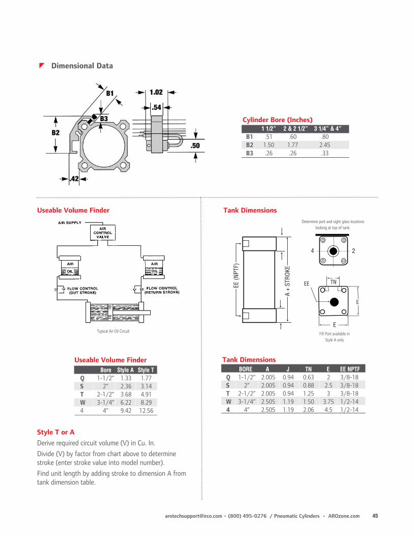
Determine port and sight glass locations looking at top of tank.
Useable Volume Finder
Typical Air Oil Circuit
EE (N
PTF)
E
E
EE TNA
+ ST
ROKE
Fill Port available in Style A only
Style T or ADerive required circuit volume (V) in Cu. In.Divide (V) by factor from chart above to determine stroke (enter stroke value into model number).Find unit length by adding stroke to dimension A from tank dimension table.
To order a reciprocating assembly, 1) Obtain model number from label on cylinder. 2) Write “RA” for reciprocating assembly 3) Using number from cylinder label, construct proper assembly number as directed below.
X - No Cushion SealsB - Cushion Both EndsC - Cushion CapH - Cushion Head
Port Location Not Used, Mounts Not Used, Stroke Not Used
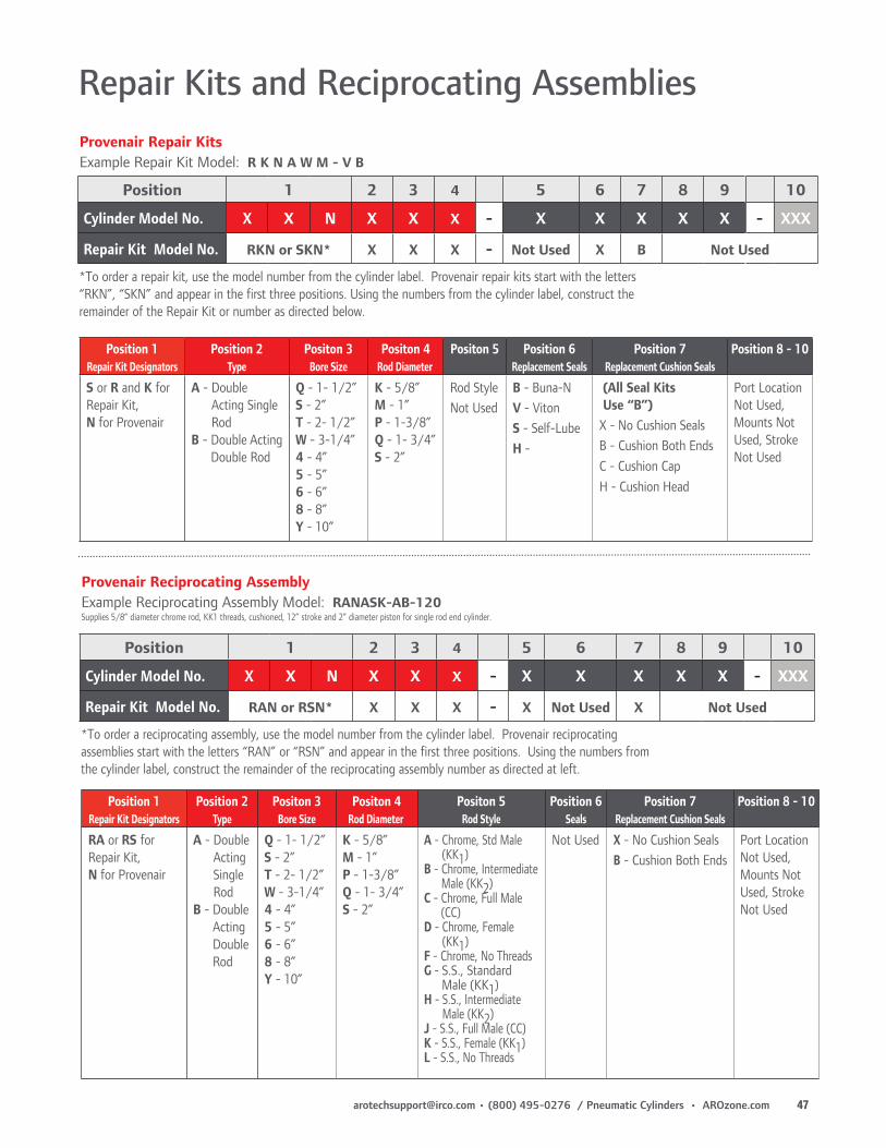
*To order a repair kit, use the model number from the cylinder label. Provenair repair kits start with the letters “RKN”, “SKN” and appear in the first three positions. Using the numbers from the cylinder label, construct the remainder of the Repair Kit or number as directed below.
Provenair Repair Kits Example Repair Kit Model: R K N A W M - V B
Position 1 2 3 4 5 6 7 8 9 10
Cylinder Model No. X X N X X X - X X X X X - XXX
Repair Kit Model No. RAN or RSN* X X X - X Not Used X Not Used
Male (KK2)J - S.S., Full Male (CC)K - S.S., Female (KK1) L - S.S., No Threads
Not Used X - No Cushion SealsB - Cushion Both Ends
Port Location Not Used, Mounts Not Used, Stroke Not Used
*To order a reciprocating assembly, use the model number from the cylinder label. Provenair reciprocating assemblies start with the letters “RAN” or “RSN” and appear in the first three positions. Using the numbers from the cylinder label, construct the remainder of the reciprocating assembly number as directed at left.
Provenair Reciprocating Assembly Example Reciprocating Assembly Model: RANASK-AB-120Supplies 5/8” diameter chrome rod, KK1 threads, cushioned, 12” stroke and 2” diameter piston for single rod end cylinder.
Premair Series Round Compact, Interchangeable Cylinders
Premair Round Compact
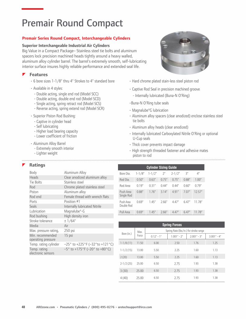
Superior Interchangeable Industrial Air Cylinders Big Value in a Compact Package– Stainless steel tie bolts and aluminum spacers lock precision machined heads tightly around a heavy walled, aluminum alloy cylinder barrel. The barrel's extremely smooth, self-lubricating interior surface insures highly reliable performance and extended seal life.
• 6 bore sizes 1-1/8" thru 4" Strokes to 4" standard bore
• Available in 4 styles:- Double acting, single end rod (Model SCC)- Double acting, double end rod (Model SCD)- Single acting, spring retract rod (Model SCS)- Reverse acting, spring extend rod (Model SCR)
• Superior Piston Rod Bushing: - Captive in cylinder head - Self lubricating
- Higher load bearing capacity - Lower coefficient of friction
tie bolts• Aluminum alloy heads (clear anodized)• Internally lubricated Carboxylated Nitrile O'Ring or optional
U-Cup seals• Thick cover prevents impact damage• High strength threaded fastener and adhesive mates
piston to rod
zFeatures
zRatings Body Aluminum Alloy Heads Clear anodized aluminum alloy Tie Bolts Stainless steel Rod Chrome plated stainless steel Piston Aluminum alloy Rod end Female thread with wrench flats Ports Position #1 Seals Internally lubricated Nitrile Lubrication Magnalube®-G Rod bushing High density iron Stroke tolerance ± 1/64" Media Air Max. pressure rating, 250 psi Min. recommended 15 psi operating pressure Temp. rating cylinder –25° to +225°F (–32°to +121°C) Temp. rating –5° to +175°F (–20° to +80°C) electronic sensors
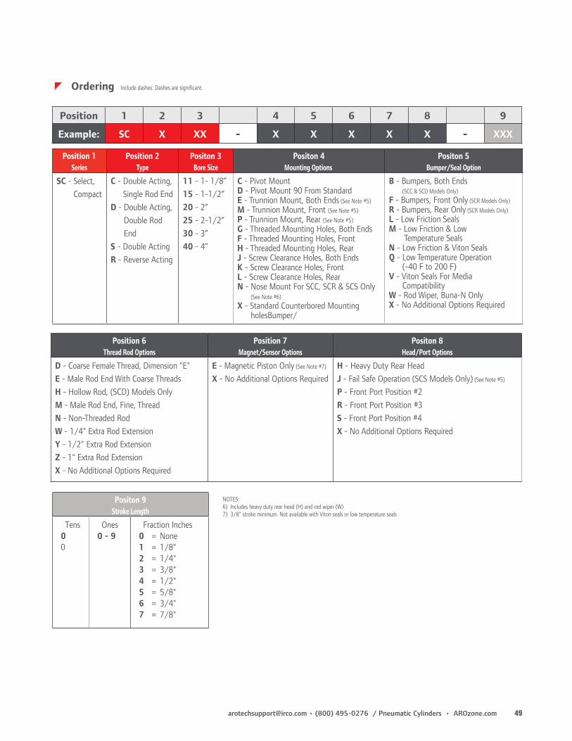
C - Pivot MountD - Pivot Mount 90 From StandardE - Trunnion Mount, Both Ends (See Note #5)M - Trunnion Mount, Front (See Note #5) P - Trunnion Mount, Rear (See Note #5)G - Threaded Mounting Holes, Both EndsF - Threaded Mounting Holes, FrontH - Threaded Mounting Holes, RearJ - Screw Clearance Holes, Both EndsK - Screw Clearance Holes, FrontL - Screw Clearance Holes, Rear N - Nose Mount For SCC, SCR & SCS Only (See Note #6) X - Standard Counterbored Mounting holesBumper/
B - Bumpers, Both Ends (SCC & SCD Models Only)F - Bumpers, Front Only (SCR Models Only)R - Bumpers, Rear Only (SCR Models Only)L - Low Friction SealsM - Low Friction & Low Temperature SealsN - Low Friction & Viton SealsQ - Low Temperature Operation (-40 F to 200 F)V - Viton Seals For Media CompatibilityW - Rod Wiper, Buna-N OnlyX - No Additional Options Required
Position 6Thread Rod Options
Position 7Magnet/Sensor Options
Positon 8Head/Port Options
D - Coarse Female Thread, Dimension "E"E - Male Rod End With Coarse ThreadsH - Hollow Rod, (SCD) Models OnlyM - Male Rod End, Fine, ThreadN - Non-Threaded Rod W - 1/4" Extra Rod ExtensionY - 1/2" Extra Rod ExtensionZ - 1" Extra Rod ExtensionX - No Additional Options Required
E - Magnetic Piston Only (See Note #7)
X - No Additional Options RequiredH - Heavy Duty Rear HeadJ - Fail Safe Operation (SCS Models Only) (See Note #5)
P - Front Port Position #2R - Front Port Position #3S - Front Port Position #4X - No Additional Options Required
Deviations from Standard Dimensions Hollow Rod Option
Hole Diameter
Bore Female RodThread
Male RodThread
1-1/8 (11) 0.22 0.16
1-1/2 (15) 0.28 0.19
2 (20) 0.38 0.25
2-1/2 (25) 0.38 0.25
3 (30) 0.44 0.31
4 (40) 0.50 0.38
‡ Heavy duty rear head is recommended for applications where the cylinder is mounted onthe front face or trunnion-mounted, and impact loading (20 or more cycles/minute) occursbetween the piston and rear head. It increases the overall length of the cylinder as shown.† A minimum stroke of 3/8” is required to sense end-of-stroke positions. For low friction sealsused in conjunction with magnetic position sensing, use “E” or “M” sensor options only.
Threaded Mounting Holes Nose MountAvailable on SCC, SCS, SCR.Included heavy duty rear head. See length adder above.
Low-profile, aluminum cylinders are designed for compact, spacesaving applications. All models have magnetic pistons and are switch-ready for accurate position sensing. Low-profile, solid state switches slide into machined grooves located on the cylinder body. Stainless steel piston rods are hard chrome plated for superior wear and corrosion resistance. Piston is attached to rod with a flat head screw to minimize pounding and vibration. Mounting through holes are threaded for easy mounting hardware installation.
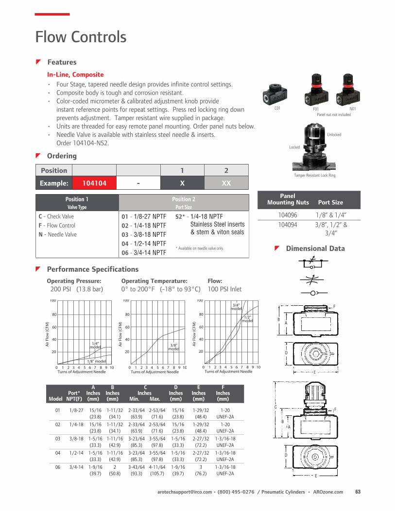
• Four Stage, tapered needle design provides infinite control settings.• Composite body is tough and corrosion resistant.• Color-coded micrometer & calibrated adjustment knob provide instant reference points for repeat settings. Press red locking ring down
prevents adjustment. Tamper resistant wire supplied in package.• Units are threaded for easy remote panel mounting. Order panel nuts below.• Needle Valve is available with stainless steel needle & inserts.
Order 104104-NS2.
Operating Pressure: Operating Temperature: Flow: 200 PSI (13.8 bar) 0° to 200°F (-18° to 93°C) 100 PSI Inlet
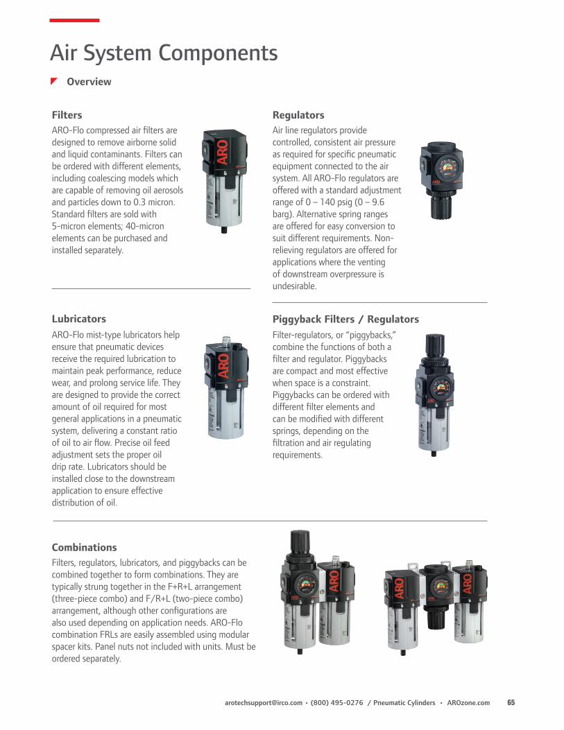
RegulatorsAir line regulators provide controlled, consistent air pressure as required for specific pneumatic equipment connected to the air system. All ARO-Flo regulators are offered with a standard adjustment range of 0 – 140 psig (0 – 9.6 barg). Alternative spring ranges are offered for easy conversion to suit different requirements. Non-relieving regulators are offered for applications where the venting of downstream overpressure is undesirable.
ARO-Flo mist-type lubricators help ensure that pneumatic devices receive the required lubrication to maintain peak performance, reduce wear, and prolong service life. They are designed to provide the correct amount of oil required for most general applications in a pneumatic system, delivering a constant ratio of oil to air flow. Precise oil feed adjustment sets the proper oil drip rate. Lubricators should be installed close to the downstream application to ensure effective distribution of oil.
Filter-regulators, or “piggybacks,” combine the functions of both a filter and regulator. Piggybacks are compact and most effective when space is a constraint. Piggybacks can be ordered with different filter elements and can be modified with different springs, depending on the filtration and air regulating requirements.
Filters, regulators, lubricators, and piggybacks can be combined together to form combinations. They are typically strung together in the F+R+L arrangement (three-piece combo) and F/R+L (two-piece combo) arrangement, although other configurations are also used depending on application needs. ARO-Flo combination FRLs are easily assembled using modular spacer kits. Panel nuts not included with units. Must be ordered separately.
FiltersARO-Flo compressed air filters are designed to remove airborne solid and liquid contaminants. Filters can be ordered with different elements, including coalescing models which are capable of removing oil aerosols and particles down to 0.3 micron. Standard filters are sold with 5-micron elements; 40-micron elements can be purchased and installed separately.
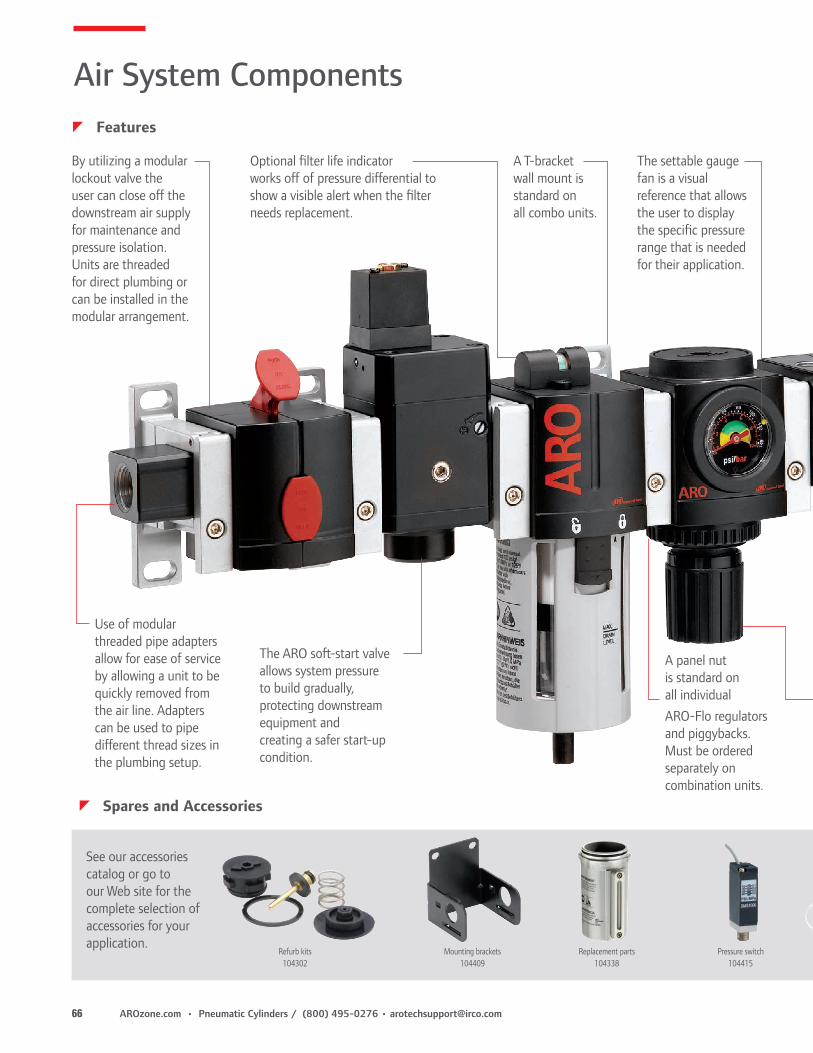
By utilizing a modular lockout valve the user can close off the downstream air supply for maintenance and pressure isolation. Units are threaded for direct plumbing or can be installed in the modular arrangement.
Use of modular threaded pipe adapters allow for ease of service by allowing a unit to be quickly removed from the air line. Adapters can be used to pipe different thread sizes in the plumbing setup.
The ARO soft-start valve allows system pressure to build gradually, protecting downstream equipment and creating a safer start-up condition.
Optional filter life indicator works off of pressure differential to show a visible alert when the filter needs replacement.
A T-bracket wall mount is standard on all combo units.
See our accessories catalog or go to our Web site for the complete selection of accessories for your application.
Pressure switch104415
Mounting brackets104409
Replacement parts104338
Refurb kits104302
A panel nut is standard on all individual ARO-Flo regulators and piggybacks. Must be ordered separately on combination units.
The settable gauge fan is a visual reference that allows the user to display the specific pressure range that is needed for their application.
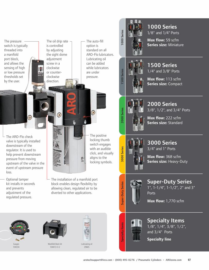
The installation of a manifold port block enables design flexibility by allowing clean, regulated air to be diverted to other applications.
The pressure switch is typically threaded into a manifold port block, and allows the sensing of high or low pressure thresholds set by the user.
The positive locking thumb switch engages with an audible click, and visually aligns to the locking symbols.
The auto-fill option is standard on all ARO-Flo lubricators. Lubricating oil can be added while lubricators are under pressure.
1000 Series1/8" and 1/4" Ports
Max flow: 59 scfmSeries size: Miniature
1500 Series1/4" and 3/8" Ports
Max flow: 113 scfmSeries size: Compact
2000 Series3/8", 1/2", and 3/4" Ports
Max flow: 222 scfmSeries size: Standard
3000 Series3/4" and 1" Ports
Max flow: 368 scfmSeries size: Heavy-Duty
Super-Duty Series1", 1-1/4", 1-1/2", 2" and 3" Ports
Max flow: 1,770 scfm
Specialty Items1/8", 1/4", 3/8", 1/2", and 3/4" Ports
Specialty line
1000
Ser
ies
1500
Ser
ies
2000
Ser
ies
3000
Ser
ies
Supe
r-D
uty
Serie
sSp
ecia
lty
Item
s
Lubricating oil29665
Manifold block kit104413-3-2
Gauges104334
The oil drip rate is controlled by adjusting the sight dome adjustment screw in a clockwise or counter-clockwise direction.
The ARO-Flo check valve is typically installed downstream of the regulator. It is used to help prevent downstream pressure from moving upstream of the valve in the event of upstream pressure loss.
Optional tamper kit installs in seconds and prevents adjustment of the regulated pressure.
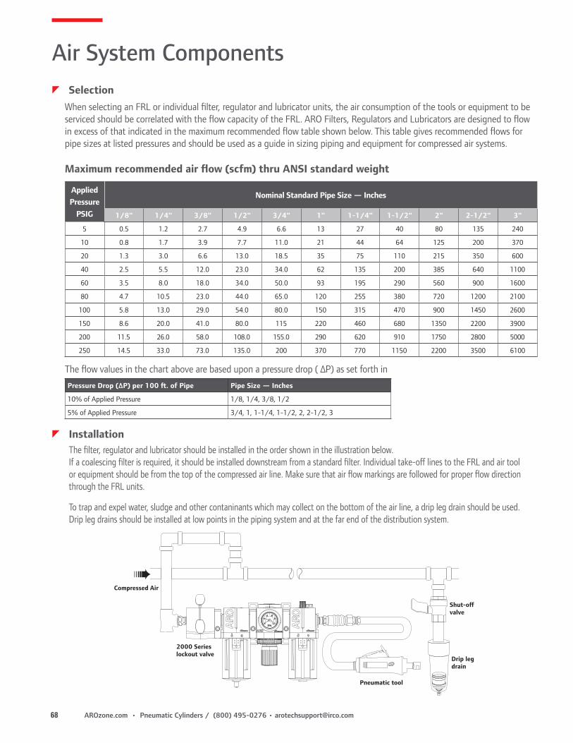
When selecting an FRL or individual filter, regulator and lubricator units, the air consumption of the tools or equipment to be serviced should be correlated with the flow capacity of the FRL. ARO Filters, Regulators and Lubricators are designed to flow in excess of that indicated in the maximum recommended flow table shown below. This table gives recommended flows for pipe sizes at listed pressures and should be used as a guide in sizing piping and equipment for compressed air systems.
The filter, regulator and lubricator should be installed in the order shown in the illustration below. If a coalescing filter is required, it should be installed downstream from a standard filter. Individual take-off lines to the FRL and air tool or equipment should be from the top of the compressed air line. Make sure that air flow markings are followed for proper flow direction through the FRL units.
To trap and expel water, sludge and other contaninants which may collect on the bottom of the air line, a drip leg drain should be used. Drip leg drains should be installed at low points in the piping system and at the far end of the distribution system.
Maximum recommended air flow (scfm) thru ANSI standard weight
CAUTION: Compounded oils containing graphite and fillers are not recommended for use with cylinders.
To obtain information or to receive technical literature for specific cylinders: contact ARO® Customer Service at (800) 495-0276 or contact your nearest ARO® distributor. Selected parts are provided in kit form. The ARO® Parts List/Service Instructions contain Repair Kit information and complete Service Parts information and are available upon request. Order Manuals as shown. The following Operator’s Manuals are available.
Air Pressure: Limited to 200 psig (14 bar)* FILTRATION: 40 Micron. Proper moisture removal and filtration of contaminates will promote good service life and operation. Install an air regulator to control the operating pressure, insure smooth operation and conserve energy.
Lubrication: All ARO® Cylinders are lubricated at the factory. This lubrication should provide satisfactory operation and cycle life. For maximum performance and life expectancy, standard air line lubrication should be used. If air line cylinders or other air line devices, used in conjunction with ARO® valve, require lubrication, be sure the lubricating oils used are compatible with the valve seals and are of sufficient viscosity to assure adequate lubrication. ARO® recommends an oil lubricant with a viscosity of 100-200 SUS at 100° F and an airline point above 200° F.
NOTICE: The use of compound oils containing graphite filters, extremely low viscosities an other non-fluid lubricants is not recommended.RECOMMENDED: ARO 29665 air line lubricator oil is available in one quart containers.
WARNINGThe following are hazards or unsafe practices which could result in severe personal injury, death or substantial property damage. Heed the following. Use safeguards. Insure that provisions are made to prevent the valve from being accidentally operated (actuated.)
Hazardous Air Pressure. Shut off, disconnect and relieve any trapped air pressure from system before performing service or maintenance.
Hazardous Voltage. Do not attempt any service without disconnecting all electrical supply sources.
* Provenair Cylinder inlet is up to 250-psi (17-bar)
General InformationzWarnings
Harmful Compressor Oils & Other Materials
zGeneral Information
Some oils used in air compressors contain chemicals harmful to Buna-N seals, if not adequately filtered at the compressor. The most common of these oils, in addition to other harmful material, are listed below.
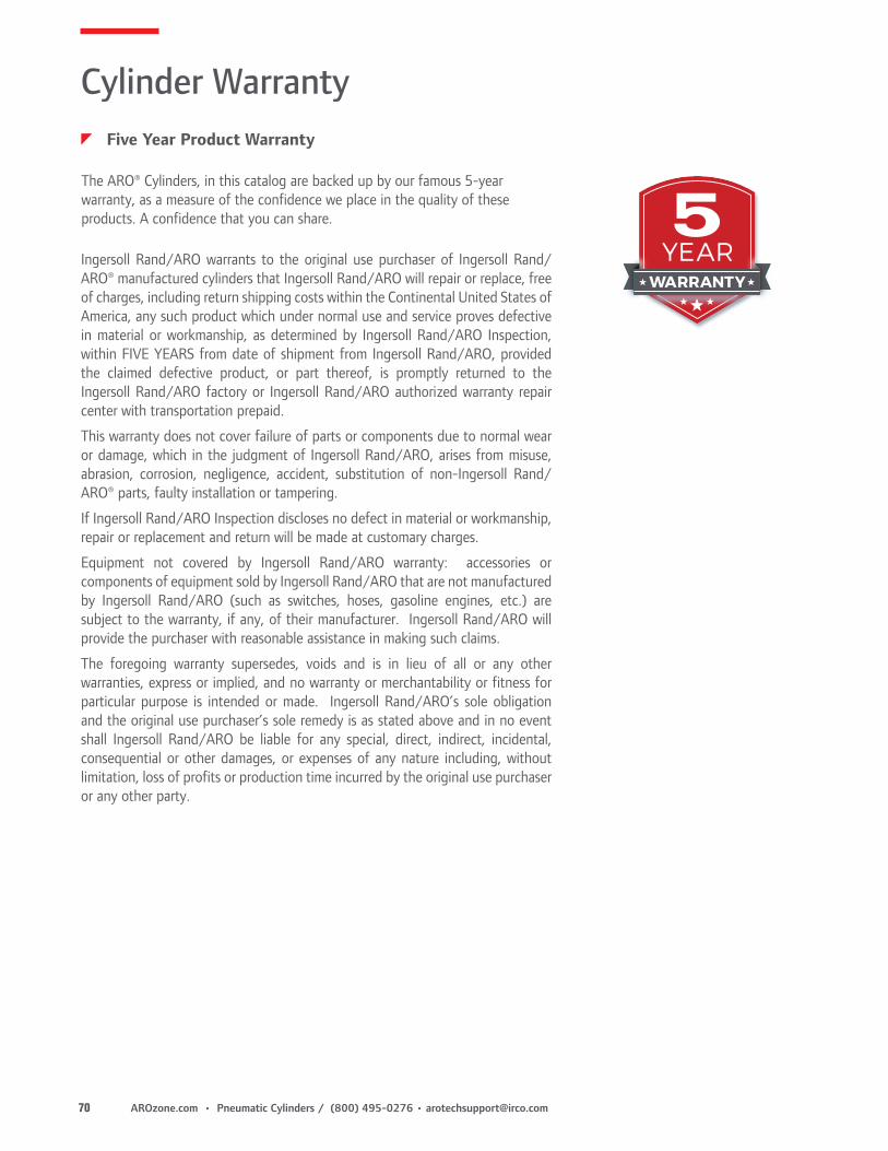
The ARO® Cylinders, in this catalog are backed up by our famous 5-year warranty, as a measure of the confidence we place in the quality of these products. A confidence that you can share.
Ingersoll Rand/ARO warrants to the original use purchaser of Ingersoll Rand/ARO® manufactured cylinders that Ingersoll Rand/ARO will repair or replace, free of charges, including return shipping costs within the Continental United States of America, any such product which under normal use and service proves defective in material or workmanship, as determined by Ingersoll Rand/ARO Inspection, within FIVE YEARS from date of shipment from Ingersoll Rand/ARO, provided the claimed defective product, or part thereof, is promptly returned to the Ingersoll Rand/ARO factory or Ingersoll Rand/ARO authorized warranty repair center with transportation prepaid.
This warranty does not cover failure of parts or components due to normal wear or damage, which in the judgment of Ingersoll Rand/ARO, arises from misuse, abrasion, corrosion, negligence, accident, substitution of non-Ingersoll Rand/ARO® parts, faulty installation or tampering.
If Ingersoll Rand/ARO Inspection discloses no defect in material or workmanship, repair or replacement and return will be made at customary charges.
Equipment not covered by Ingersoll Rand/ARO warranty: accessories or components of equipment sold by Ingersoll Rand/ARO that are not manufactured by Ingersoll Rand/ARO (such as switches, hoses, gasoline engines, etc.) are subject to the warranty, if any, of their manufacturer. Ingersoll Rand/ARO will provide the purchaser with reasonable assistance in making such claims.
The foregoing warranty supersedes, voids and is in lieu of all or any other warranties, express or implied, and no warranty or merchantability or fitness for particular purpose is intended or made. Ingersoll Rand/ARO’s sole obligation and the original use purchaser’s sole remedy is as stated above and in no event shall Ingersoll Rand/ARO be liable for any special, direct, indirect, incidental, consequential or other damages, or expenses of any nature including, without limitation, loss of profits or production time incurred by the original use purchaser or any other party.
Cylinder WarrantyzFive Year Product Warranty
ARO® is a brand of Ingersoll Rand. Ingersoll Rand (NYSE:IR) advances the quality of life by creating comfortable, sustainable and efficient environments. Our people and our family of brands—including Club Car®, Ingersoll Rand®, Thermo King® and Trane®—work together to enhance the quality and comfort of air in homes and buildings; transport and protect food and perishables; and increase industrial productivity and efficiency. We are a $14 billion global business committed to a world of sustainable progress and enduring results. For more information, visit www.ingersollrand.com.