152
PNEUMATIC DIRECTIONAL CONTROL VALVES INDUSTRIAL TYPE
PNEUMATIC DIRECTIONAL CONTROL VALVES INDUSTRIAL TYPE
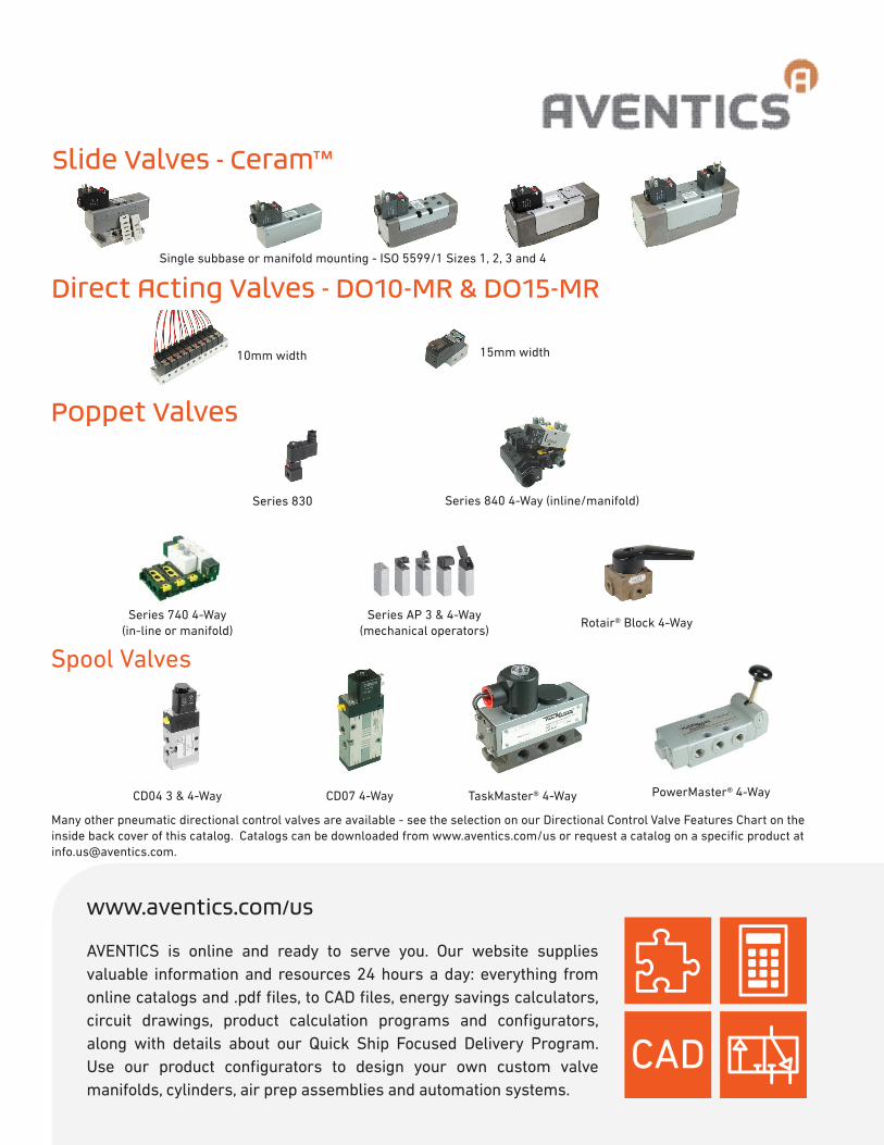
Slide Valves - Ceram™
www.aventics.com/us
AVENTICS is online and ready to serve you. Our website supplies valuable information and resources 24 hours a day: everything from online catalogs and .pdf files, to CAD files, energy savings calculators, circuit drawings, product calculation programs and configurators, along with details about our Quick Ship Focused Delivery Program. Use our product configurators to design your own custom valve manifolds, cylinders, air prep assemblies and automation systems.
Single subbase or manifold mounting - ISO 5599/1 Sizes 1, 2, 3 and 4
Direct Acting Valves - DO10-MR & DO15-MR
10mm width 15mm width
Poppet Valves
Series 830 Series 840 4-Way (inline/manifold)
Spool Valves
Series 740 4-Way (in-line or manifold)
Series AP 3 & 4-Way(mechanical operators)
Rotair® Block 4-Way
CD04 3 & 4-Way CD07 4-Way TaskMaster® 4-Way PowerMaster® 4-Way
Many other pneumatic directional control valves are available - see the selection on our Directional Control Valve Features Chart on the inside back cover of this catalog. Catalogs can be downloaded from www.aventics.com/us or request a catalog on a specific product at [email protected].

Pneumatic Directional Control Valves AVENTICS Corporation 3
TABLE OF CONTENTS PAGE
Slide Valves Ceram™ 4-way Directional Slide Valves (sliding ceramic plates)………………………….. 5 ISO 5599/1sizes 1, II, III & IV, 1/4”, 3/8”, 3/4” & 1” port size. Cv = 1.1, 2.4, 4.3, & 7.5. Subbase and manifold mounted 4-way 2 and 3 position solenoids & air pilot operators.
Direct Operated Valves Series DO10-MR 2/2 and 3/2 valves, 10 mm body width, Cv = .014………………………. 39 Series DO15-MR 2/2 and 3/2 valves, 15 mm body width, Cv up to 0.05………………….. 44 Poppet Valves Series 830™ 3-Way Directional Poppet Valve……………………………………………….. 50 1/8” NPT or 10-32 port size, Cv =0.06 with 3 SCFM @ 150 psi, locking manual override, manifold capabilities, strain relief connector included with valve. Series 840™ 4-Way Directional Poppet Valve……………………………………………….. 51 Polyacetal construction. Built-in tube fittings for 1/4” O.D. tubing. Cv = 0.2. Single and double solenoid, plus single and double air pilot operators. Inline or modular manifold. Series 740™ 4-Way Directional Poppet Valve……………………………………………….. 56 Polyacetal construction. Integral tube fittings for 1/4” and 5/16” O.D. tubing. Cv = 0.7. Single and double solenoid, plus single and double air pilot operators. Built-in exhaust flow controls in two position valves. Inline or modular manifold system. Series AP 3-Way and 4-Way Directional Poppet Valves……………………………………. 66 3/2 and 4/2 mechanically operated valves with flows up to 0.60 Cv. Operators include plunger, roller, pushbutton, roller lever, lever, control panel installation versions. Rotair® Block 4-Way Directional Poppet Valve……………………………………………….. 80 1/8”, 1/4” & 3/8” NPT port sizes. Cv = 1.0, 1.1 & 1.2. 4-way, 2 and 3 position, detented, handle operated, closed and exhaust open center.
Spool Valves Series CD04 4-Way Directional Spool Valve…………………………………………………. 82 1/8” PTF and G1/8 ported 5/2 valves, 0.9 Cv. Single and double solenoid, single and double air pilot, plus mechanical operators. Series CD07 4-Way Directional Spool Valve…………………………………………………. 110 1/4” NPT ported valves, 1.1 Cv. 4-way, two and three position solenoid, manual and air pilot operated. Standard and explosion proof operators available. TaskMaster® 4-Way Directional Spool Valve…………………………………………………. 120 1/4” and 3/8” NPT subplate models. Cv = 1.0. 4-way function, solenoid, air pilot, lever and button operators. PowerMaster® 4-Way Directional Spool Valve………………………………………………. 124 1/4” , 3/8”, 1/2”, 1” & 1-1/4” NPT port sizes. Cv ranges from 2.39 to 15.75. Tapped body models. Solenoid, air pilot and mechanical operators.
Technical Section Valve Diagrams, Application Sketches, Sizing Guide, etc………………………………….. 132 Including vacuum and dual pressure applications, metric conversion chart. Solenoid Connectors……………………………………………………………………………. 145 Electrical Hook-up Information; Cables……………………………………………………….. 146 Surge Suppression………………………………………………………………………………. 147 Valve Features Summary Chart………………………………………………………….......... 148

4 Pneumatic Directional Control Valves AVENTICS Corporation
Ceram™ Valves, ISO 5599-1 Sizes 1-4 Index
Needle Bearing Assembly
Pilot chamber and piston
Static ceramic plate
Dynamic ceramic plate
TABLE OF CONTENTS PAGE Specifications and features ................................................................. 5-6 Model number identification ................................................................. 7 Single solenoid, metal spring return .................................................... 8 Single solenoid, air spring return ......................................................... 9 Double solenoid, 5/2 ............................................................................ 10 Single air pilot, metal and air spring return .......................................... 11 Double air pilot, 5/2 .............................................................................. 12 Double solenoid, 5/3, closed center ..................................................... 13 Double solenoid, 5/3, exhaust open center ......................................... 14 Double air pilot, 5/3, closed center and exhaust open center .............. 15 cURus approved operators .................................................................. 16 Externally piloted valves without coil ................................................... 16 CSA approved operator: 3 or 5 pin connections .................................. 17 4 pin M12 connections ......................................................................... 18 CSA appr. operator, single 4/5 pin conn. for dbl. solenoid valves ....... 19 Explosion proof and intrinsically safe solenoid valves ......................... 20 Repair kits and parts ............................................................................ 21 Subbase and manifolds, Size 1 ........................................................... 22 Manifold accessories, Size 1 ............................................................... 23-24 Subbase and manifolds, Size 2 ........................................................... 25 Manifold accessories, Size 2 ............................................................... 26-27 Subbase and manifolds, Size 3 ........................................................... 28 Manifold accessories, Size 3 ............................................................... 29 Subbase and manifolds, Size 4 ........................................................... 30-31 Subbase and manifold accessories, Size 4 ......................................... 31 Air pilot valve manifolds, Size 1-3 ........................................................ 32-34 Pressure gauges for sandwich regulators ........................................... 35 Internal to external pilot field conversion, Sizes 1 and 2 ..................... 36 Internal to external pilot field conversion, Sizes 3 and 4 ..................... 37 Piping procedures ................................................................................ 38

Pneumatic Directional Control Valves AVENTICS Corporation 5
Ceram™ Valves, ISO 5599-1 Sizes 1-4 Specifications and features
Specified by industries that demand tough valves due to their harsh operating environment. Ceram™ valves are very prevalent in industries where ordinary valves just don’t last. Industries such as: tire plants, foundries, paper mills, steel plants, concrete batch plants, sawmills, plywood and board plants, automotive assembly, glass manufacturers, rubber and plastics, sheet metal fabrication, etc.
Eliminate downtime—they don’t stick Normal air valves can stick or jam and cause start-up problems because of their inability to handle accumulations of dir, dust, oil or water in air lines. Not with the Ceram valve. There’s no gap between the plates for dirt and oil to accumulate. The plates are finished so precise that they act like sliding magnets or jo blocks. Solenoid operators of the same voltage on standard valves are interchangeable between all sizes, reducing spare parts inventory and downtime. They work great in normal applications too Just because they are so popular in harsh environments, don’t think they won’t work great in a more normal application. Ceram valves save air and money The tight shut-off with Ceram valves eliminates costly loss of air that is common in other designs. Compressed air that you pay for. Overcomes design limitations of other valves Lapped spool valves normally have a small gap between spool and sleeve that is prone to oil and dirt accumulation, resulting in sticking and the waste of air. Packed spool valves using elastomer seals are subject to deterioration and excessive wear when contamination and/or incompatible lubricants are present.
Valve Size Ports NPT, ISO G(BSPP) Cv S.C.F.M.*
Size 1 1/4”, 3/8” 1.1 40 SCFM
Size 2 3/8”, 1/2” 2.4 86 SCFM
Size 3 1/2”, 3/4” 4.3 155 SCFM
Size 4 3/4”,1” 7.5 269 SCFM
Valve Sizes/Specifications
*Flow measured with 87 psi (6 bar) supply pressure and 14.5 psi (1 bar) pressure drop across the valve.
Extended life Years of proven field service verifies an anticipated life of 150 million cycles even under adverse conditions. World Standard ISO mounting ISO 5599/1 mounting dimensions mean that wherever you send it, it’s interchangeable with other ISO valves. Four basic valves sizes - ISO 1 through 4 with subbases or manifolds with NPT or ISO G (BSPP) ports.
Concrete batching plant application. Ceram valves withstand harsh conditions and dirty air without “sticking”.

6 Pneumatic Directional Control Valves AVENTICS Corporation
Summary of Specifications For Ceram Valves TECHNICAL DATA: Port Sizes: 1/4” - 3/8” ISO Size 1, 3/8” - 1/2” ISO Size 2 1/2” - 3/4” ISO Size 3, 3/4” - 1” ISO Size 4 Working Pressure: 0 to 150 PSI (0 to 10.3 bar) (Intrinsically Safe versions: Maximum internal pilot valve pressure is 115 PSI or 7.9 bar) Vacuum applications: to 24” Hg Pilot Pressure: SIZES 1 & 2 29 PSI (2.0 bar) minimum, all 2 position valves 44 PSI (3.0 bar) minimum, all 3 position valves 150 PSI (10.3 bar) maximum (Intrinsically Safe versions: Maximum external pilot pressure is 115 PSI or 7.9 bar) SIZES 3 & 4 36 PSI (2.5 bar) minimum, all 2 position valve 44 PSI (3.0 bar) minimum, all 3 position valve 150 PSI(10.3 bar) maximum (Intrinsically Safe versions: Maximum external pilot pressure is 115 PSI or 7.9 bar) Flow: Valve Size 1 2 3 4 Cv 1.1 2.4 4.3 7.5 Nl/min 1100 2400 4300 7500 Temperature Range: Solenoid Valves: +5°F to +150°F (-15°C to 66°C) (-10°F or –23°C operation possible with low temperature solenoid operators. Available for 2-position double solenoid and air Spring return valves.) Air Pilot Valves: -10°F to +175°F (-23°C to 79°C) Media: Air, either Lubricated or Non-lubricated Service Life: over 150 million Cycles with or without Line Lubrication Material: Body - Die Cast Anodized Aluminum (Sizes 2 - 4) Die Cast Zinc (Size 1) Valve Elements - Ceramic Slide Plates (AI2O3) Combination Manual Override: Explosion-proof models: Non-locking only Other models: Locking & Non-Locking sizes 1 - 4 (3 and 4: Oct. ‘92 & later) Non-Locking sizes 3 & 4 (Prior to Oct. ‘92)
Ceram™ Valves, ISO 5599-1 Sizes 1-4 Specifications and features
ELECTRICAL DATA:
ISO Valve
Size
Standard Voltages (All coils are rated for
continuous duty)
Power Consumption
Inrush Holding
1 and 2 (3 and 4 Oct. ‘92
and later)
24 VAC - 50/60 Hz 110 VAC - 50 Hz/120 VAC - 60 Hz 220 VAC - 50 Hz/240 VAC - 60 Hz
6.4 VA
3.7 VA
12, 24 VDC 2.7 W
120, 240 VAC (50/60 Hz) 15.6 VA 9.4 VA
12, 24 VDC 6.1 W
3 and 4 (Prior to Oct.
‘92)
Voltage Tolerance: +/- 10% (Except for Explosion proof and Intrinsically safe solenoids.) All standard valves are rated for NEMA 4. SOLENOID CONNECTORS AND SUBBASES: Plug-in solenoid connectors conform to DIN standard #43650 and must be ordered separately. Order one connector per solenoid. Connector options Include strain relief and one-half inch (1/2”) conduit. Both are available in Lighted and non-lighted versions. 1/2” conduit connector also available in metallic version; see page main solenoid connectors page. Subbases, manifold and accessories are ordered separately.
FEATURES • Ceramic plates guaranteed for life of valve • Sliding ceramic plates form seal • Operates with or without line lubrication • Interchangeable with other ISO valves • Expected service life exceeds 150 million
cycles • NEMA 4 Standard • Sub-bases and manifolds available 1/4” thru
1” NPT ISO G1/8 to G1 piping • Wide range of accessories, including
sandwich speed controls and regulators • Explosion-proof and intrinsically safe
solenoids available. • Brad Harrison® Connector Solenoids • cURus (Dual CSA / UL Recognized)
solenoids
ISO I pictured

Pneumatic Directional Control Valves AVENTICS Corporation 7
Model Code Identification
Ceram™ Valves, ISO 5599-1 Sizes 1-4 Model code identification
NOTE: The previous version of the GS series was the GA series. The GS valves are direct functional/dimensional replacements for the previous GA series. Size I valves are now GT series, and are direct functional/dimensional replacements. Also, there are various special CERAM valves which have old part numbers that begin with “P” (such as P –069431-00001). Effective April 2008, part numbers begin with “R” and are 10 digits. For online part number crossover: www.aventics.com/us/ceram
GX - 0X 00 X X - OPERATORS
“14” END “12” END
G X X (SIZE) 00 X (DESCRIPTION) X (Solenoid Arrangement)
4-Way, 5-Ported CERAM Valve
S or T 1 ISO 1 1 3 Position Valves, Exhaust Open Ctr. Ext. Pilot 0 None
2 ISO 2 2 3 Position Valves, Closed Ctr. Ext. Pilot 1 Single Solenoid
S 3 ISO 3 3 3 Position Valves, Exhaust Open Ctr. Int. Pilot 2 Double Solenoid
4 ISO 4 4 3 Position Valves, Closed Ctr. Internal Pilot
5 2 Position Valves, Ext. Pilot
6 2 Position Valves, Int. Pilot
3rd and 4th digits are always zero
0
0
0
0
0
VALVE OPERATORS 02 2 or 3 Positon ANSI 4 pin MicroConnection 24 VDC
03 2 or 3 Position ANSI 3 pin MiniConnection 120 VAC 50/60 Hz
05 2 or 3 Position ANSI 5 pin MiniConnection 120 VAC 50/60
06 2 or 3 Position ANSI 3 pin MiniConnection 24 VDC
07 2 or 3 Position ANSI 5 pin Mini.Dbl.Sol/Sgl.Conn.120 VAC 50/60 Hz
08 2 or 3 Position ANSI 5 pin Mini.Dbl.Sol/Sgl.Conn.24 VDC
09 2 or 3 Position ANSI 4 pin Micro.Dbl.Sol/Sgl.Conn.24 VDC
10 2 or 3 Position ANSI 5 pin MiniConnection 24 VDC
11 2 Position Low Temp Operator 120 VAC 50/60 Hz
13 2 Position Low Temp Operator 24 VDC
•
•
•
•
•
•
•
•
14 2 Position 240 VAC 50/60 Hz Low Temp
15 2 or 3 Position 12 VAC 50/60 Hz
16 2 or 3 Position 480 VAC 50/60 Hz or 253 VDC
17 2 or 3 Position 36 VDC
18 2 or 3 Position 76 VDC
19 2 or 3 Position 125 VDC
20 2 or 3 Position 24 VDC 2.1 W (For Contact Bridge)
24 2 Position 120 VAC 50/60 Hz
26 3 Position with Centering Springs 120 VAC 50/60 Hz
27 2 Position 240 VAC 50/60 Hz
29 3 Position with Centering Springs 240 VAC 50/60 Hz
33 Air Pilot—2 Position Valves
35 Air Pilot with Centering Springs—3 Position Valves
36 2 Position 12 VDC
38 3 Position with Centering Springs 12 VDC
39 2 Position 24 VDC
40 Metal Spring Return
41 3 Position with Centering Springs 24 VDC
43 Explosion Proof 2 Position 120 VAC 50/60 Hz
46 Explosion Proof 2 Position 24 VDC
49 Explosion Proof 2 Position 240 VAC 50/60 Hz
†
51 † Air Spring Return
53 Explosion Proof 3 Pos. w/ Centering Springs 120 VAC 50/60 Hz
56 Explosion Proof 3 Pos. w/ Centering Springs 24 VDC
57 2 or 3 Position cURus 120 VAC 50/60 Hz (dual UR/CSA)
58 2 or 3 Position cURus 24 VDC (dual UR/CSA)
59 Explosion Proof 3 Pos. w/ Centering Springs 240 VAC 50/60 Hz
61 2 Position 24 VAC 50/60 Hz
62 3 Position with Centering Springs 24 VAC 50/60 Hz
90 2 or 3 Position Factory Mutual Approved Intrinsically Safe 24 VDC
† Used on “12” end only. • ANSI Connection universally known as Brad Harrison®.
8 Pneumatic Directional Control Valves AVENTICS Corporation
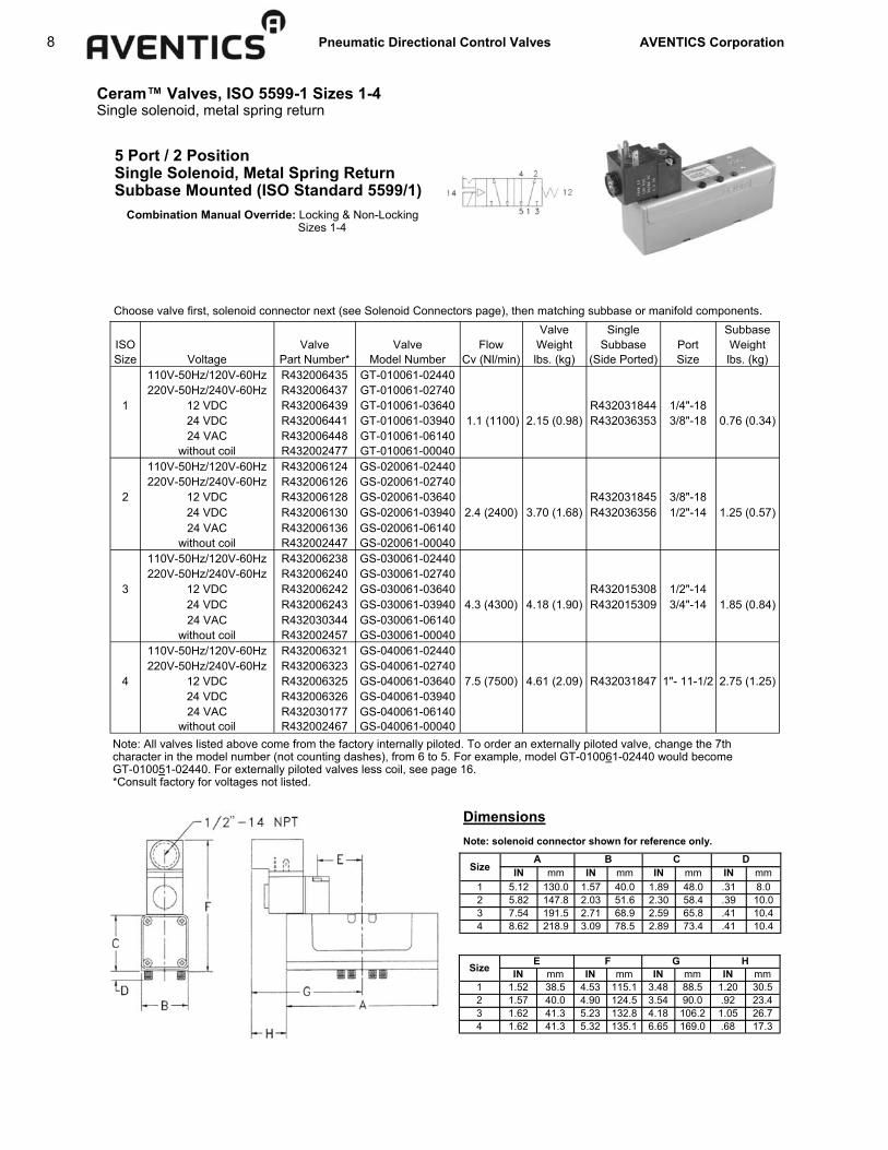
Ceram™ Valves, ISO 5599-1 Sizes 1-4 Single solenoid, metal spring return
Choose valve first, solenoid connector next (see Solenoid Connectors page), then matching subbase or manifold components.
5 Port / 2 Position Single Solenoid, Metal Spring Return Subbase Mounted (ISO Standard 5599/1) Combination Manual Override: Locking & Non-Locking Sizes 1-4
Valve Single Subbase ISO Valve Valve Flow Weight Subbase Port Weight Size Voltage Part Number* Model Number Cv (Nl/min) lbs. (kg) (Side Ported) Size lbs. (kg)
110V-50Hz/120V-60Hz R432006435 GT-010061-02440 220V-50Hz/240V-60Hz R432006437 GT-010061-02740
1 12 VDC R432006439 GT-010061-03640 R432031844 1/4"-18 24 VDC R432006441 GT-010061-03940 1.1 (1100) 2.15 (0.98) R432036353 3/8"-18 0.76 (0.34) 24 VAC R432006448 GT-010061-06140 without coil R432002477 GT-010061-00040 110V-50Hz/120V-60Hz R432006124 GS-020061-02440 220V-50Hz/240V-60Hz R432006126 GS-020061-02740
2 12 VDC R432006128 GS-020061-03640 R432031845 3/8"-18 24 VDC R432006130 GS-020061-03940 2.4 (2400) 3.70 (1.68) R432036356 1/2"-14 1.25 (0.57) 24 VAC R432006136 GS-020061-06140
without coil R432002447 GS-020061-00040 110V-50Hz/120V-60Hz R432006238 GS-030061-02440 220V-50Hz/240V-60Hz R432006240 GS-030061-02740 3 12 VDC R432006242 GS-030061-03640 R432015308 1/2"-14 24 VDC R432006243 GS-030061-03940 4.3 (4300) 4.18 (1.90) R432015309 3/4"-14 1.85 (0.84) 24 VAC R432030344 GS-030061-06140 without coil R432002457 GS-030061-00040 110V-50Hz/120V-60Hz R432006321 GS-040061-02440 220V-50Hz/240V-60Hz R432006323 GS-040061-02740 4 12 VDC R432006325 GS-040061-03640 7.5 (7500) 4.61 (2.09) R432031847 1"- 11-1/2 2.75 (1.25) 24 VDC R432006326 GS-040061-03940 24 VAC R432030177 GS-040061-06140 without coil R432002467 GS-040061-00040
Note: All valves listed above come from the factory internally piloted. To order an externally piloted valve, change the 7th character in the model number (not counting dashes), from 6 to 5. For example, model GT-010061-02440 would become GT-010051-02440. For externally piloted valves less coil, see page 16. *Consult factory for voltages not listed.
Size A B C
IN mm IN mm IN mm IN mm 1 5.12 130.0 1.57 40.0 1.89 48.0 .31 8.0 2 5.82 147.8 2.03 51.6 2.30 58.4 .39 10.0 3 7.54 191.5 2.71 68.9 2.59 65.8 .41 10.4 4 8.62 218.9 3.09 78.5 2.89 73.4 .41 10.4
D
Size E F G IN mm IN mm IN mm IN mm
1 1.52 38.5 4.53 115.1 3.48 88.5 1.20 30.5 2 1.57 40.0 4.90 124.5 3.54 90.0 .92 23.4 3 1.62 41.3 5.23 132.8 4.18 106.2 1.05 26.7 4 1.62 41.3 5.32 135.1 6.65 169.0 .68 17.3
H
Dimensions Note: solenoid connector shown for reference only.

Pneumatic Directional Control Valves AVENTICS Corporation 9
Ceram™ Valves, ISO 5599-1 Sizes 1-4 Single solenoid, air spring return
Note: All valves listed above come from the factory internally piloted. To order an externally piloted valve, change the 7th character in the model number (not counting dashes), from 6 to 5. For example, model GT-010061-02451 would become GT-010051-02451. For externally piloted valves less coil, see page 16. *Consult factory for voltages not listed.
5 Port / 2 Position Single Solenoid, Air Spring Return Subbase Mounted (ISO Standard 5599/1) Combination Manual Override: Locking & Non-Locking Sizes 1-4
Choose valve first, solenoid connector next (see Solenoid Connectors page), then matching subbase or manifold components. Valve Single Subbase ISO Valve Valve Flow Weight Subbase Port Weight Size Voltage Part Number* Model Number Cv (Nl/min) lbs. (kg) (Side Ported) Size lbs. (kg)
110V-50Hz/120V-60Hz R432006436 GT-010061-02451 220V-50Hz/240V-60Hz R432006438 GT-010061-02751
1 12 VDC R432006440 GT-010061-03651 R432031844 1/4"-18 24 VDC R432006442 GT-010061-03951 1.1 (1100) 2.15 (0.98) R432036353 3/8"-18 0.76 (0.34) 24 VAC R432006449 GT-010061-06151 without coil R432002478 GT-010061-00051 110V-50Hz/120V-60Hz R432006125 GS-020061-02451 220V-50Hz/240V-60Hz R432006127 GS-020061-02751
2 12 VDC R432006129 GS-020061-03651 R432031845 3/8"-18 24 VDC R432006131 GS-020061-03951 2.4 (2400) 3.70 (1.68) R432036356 1/2"-14 1.25 (0.57) 24 VAC R432006137 GS-020061-06151
without coil R432002448 GS-020061-00051 110V-50Hz/120V-60Hz R432006239 GS-030061-02451 220V-50Hz/240V-60Hz R432006241 GS-030061-02751 3 12 VDC R432030345 GS-030061-03651 R432015308 1/2"-14 24 VDC R432006244 GS-030061-03951 4.3 (4300) 4.18 (1.90) R432015309 3/4"-14 1.85 (0.84) 24 VAC R432030343 GS-030061-06151 without coil R432002458 GS-030061-00051 110V-50Hz/120V-60Hz R432006322 GS-040061-02451 220V-50Hz/240V-60Hz R432006324 GS-040061-02751 4 12 VDC R432030378 GS-040061-03651 7.5 (7500) 4.61 (2.09) R432031847 1"- 11-1/2 2.75 (1.25) 24 VDC R432006327 GS-040061-03951 24 VAC R432030352 GS-040061-06151 without coil R432002468 GS-040061-00051
Dimensions Note: solenoid connector shown for reference only.
Size A B C
IN mm IN mm IN mm IN mm 1 5.12 130.0 1.57 40.0 1.89 48.0 .31 8.0 2 5.82 147.8 2.03 51.6 2.30 58.4 .39 10.0 3 7.54 191.5 2.71 68.9 2.59 65.8 .41 10.4 4 8.62 218.9 3.09 78.5 2.89 73.4 .41 10.4
D
Size E F G IN mm IN mm IN mm IN mm
1 1.52 38.5 4.53 115.1 3.48 88.5 1.20 30.5 2 1.57 40.0 4.90 124.5 3.54 90.0 .92 23.4 3 1.62 41.3 5.23 132.8 4.18 106.2 1.05 26.7 4 1.62 41.3 5.32 135.1 6.65 169.0 .68 17.3
H

10 Pneumatic Directional Control Valves AVENTICS Corporation
Ceram™ Valves, ISO 5599-1 Sizes 1-4 Double solenoid, 5/2
5 Port / 2 Position Double Solenoid Subbase Mounted (ISO Standard 5599/1) Combination Manual Override: Locking & Non-Locking Sizes 1-4
Choose valve first, solenoid connector next (see Solenoid Connectors page), then matching subbase or manifold components.
Note: All valves listed above come from the factory internally piloted. To order an externally piloted valve, change the 7th character in the model number (not counting dashes), from 6 to 5. For example, model GT-010062-02424 would become GT-010052-02424. For externally piloted valves less coils, see page 16. *Consult factory for voltages not listed.
Valve Single Subbase ISO Valve Valve Flow Weight Subbase Port Weight Size Voltage Part Number* Model Number Cv (Nl/min) lbs. (kg) (Side Ported) Size lbs. (kg)
110V-50Hz/120V-60Hz R432006471 GT-010062-02424 220V-50Hz/240V-60Hz R432006472 GT-010062-02727
1 12 VDC R432006473 GT-010062-03636 R432031844 1/4"-18 24 VDC R432006474 GT-010062-03939 1.1 (1100) 3.21 (1.46) R432036353 3/8"-18 0.76 (0.34) 24 VAC R432006478 GT-010062-06161 without coil R432002479 GT-010062-00000 110V-50Hz/120V-60Hz R432006156 GS-020062-02424 220V-50Hz/240V-60Hz R432006157 GS-020062-02727
2 12 VDC R432030350 GS-020062-03636 R432031845 3/8"-18 24 VDC R432006158 GS-020062-03939 2.4 (2400) 4.75 (2.15) R432036356 1/2"-14 1.25 (0.57) 24 VAC R432006162 GS-020062-06161
without coil R432002449 GS-020062-00000 110V-50Hz/120V-60Hz R432006265 GS-030062-02424 220V-50Hz/240V-60Hz R432006266 GS-030062-02727 3 12 VDC R432030342 GS-030062-03636 R432015308 1/2"-14 24 VDC R432006267 GS-030062-03939 4.3 (4300) 4.99 (2.26) R432015309 3/4"-14 1.85 (0.84) 24 VAC R432030341 GS-030062-06161 without coil R432002459 GS-030062-00000 110V-50Hz/120V-60Hz R432006339 GS-040062-02424 220V-50Hz/240V-60Hz R432006340 GS-040062-02727 4 12 VDC R432030353 GS-040062-03636 7.5 (7500) 5.42 (2.46) R432031847 1"- 11-1/2 2.75 (1.25) 24 VDC R432006341 GS-040062-03939 24 VAC R432030178 GS-040062-06161 without coil R432002469 GS-040062-00000
Dimensions Note: solenoid connector shown for reference only.
Size A B C E IN mm IN mm IN mm IN mm IN mm
1 5.12 130.0 1.57 40.0 1.89 48.0 .31 8.0 1.52 38.5 2 5.82 147.8 2.03 51.6 2.30 58.4 .39 10.0 1.57 40.0 3 7.54 191.5 2.71 68.9 2.59 65.8 .41 10.4 1.62 41.3 4 8.62 218.9 3.09 78.5 2.89 73.4 .41 10.4 1.62 41.3
D
Size F G H K IN mm IN mm IN mm IN mm IN mm
1 4.53 115.1 3.48 88.5 6.97 177.0 3.03 77.0 1.20 30.5 2 4.90 124.5 3.54 90.0 7.09 180.0 3.15 80.0 .92 23.4 3 5.23 132.8 4.18 106.2 8.36 212.3 3.25 82.6 1.05 26.7 4 5.32 135.1 6.65 169.0 13.31 338.1 3.25 82.6 .68 17.3
J

Pneumatic Directional Control Valves AVENTICS Corporation 11
Ceram™ Valves, ISO 5599-1 Sizes 1-4 Single air pilot, metal and air spring return
5 Port / 2 Position Single Air Pilot/Metal Spring Return & Single Air Pilot/Air Spring Return (ISO Standard 5599/1)
Choose valve first, then matching subbase or manifold components. Single Air Pilot/Metal Spring Return Valve Single Subbase ISO Valve Valve Flow Weight Subbase Port Weight Size Part Number Model Number Cv (Nl/min) lbs. (kg) (Side Ported) Size lbs. (kg)
1 R432006393 GT-010050-03340 1.1 (1100) 1.22 (0.55) R432031844 1/4"-18 0.76 (0.34) R432036353 3/8"-18
R432006085 GS-020050-03340 2.4 (2400) 2.77 (1.26) R432031845 3/8"-18 1.25 (0.57) R432036356 1/2"-14
3 R432006204 GS-030050-03340 4.3 (4300) 3.37 (1.53) R432015308 1/2"-14 1.85 (0.84) R432015309 3/4"-14
4 R432006297 GS-040050-03340 7.5 (7500) 3.80 (1.72) R432031847 1"- 11-1/2 2.75 (1.25)
2
Single Air Pilot/Air Spring Return Valve Single Subbase ISO Valve Valve Flow Weight Subbase Port Weight Size Part Number Model Number Cv (Nl/min) lbs. (kg) (Side Ported) Size lbs. (kg)
1 R432006394 GT-010050-03351 1.1 (1100) 1.22 (0.55) R432031844 1/4"-18 0.76 (0.34) R432036353 3/8"-18
2 R432006086 GS-020050-03351 2.4 (2400) 2.77 (1.26) R432031845 3/8"-18 1.25 (0.57) R432036356 1/2"-14
R432006205 GS-030050-03351 4.3 (4300) 3.37 (1.53) R432015308 1/2"-14 1.85 (0.84) R432015309 3/4"-14
4 R432006298 GS-040050-03351 7.5 (7500) 3.80 (1.72) R432031847 1"- 11-1/2 2.75 (1.25)
3
Dimensions
Size A B C E
IN mm IN mm IN mm IN mm IN mm 1 5.12 130.0 1.57 40.0 1.89 48.0 .31 8.0 1.52 38.5 2 5.82 147.8 2.03 51.6 2.30 58.4 .39 10.0 1.57 40.0 3 7.54 191.5 2.71 68.9 2.59 65.8 .41 10.4 1.62 41.3 4 8.62 218.9 3.09 78.5 2.89 73.4 .41 10.4 1.62 41.3
D

12 Pneumatic Directional Control Valves AVENTICS Corporation
Ceram™ Valves, ISO 5599-1 Sizes 1-4 Double air pilot, 5/2
5 Port / 2 Position Double Air Pilot/ Subbase Mounted (ISO Standard 5599/1)
Choose valve first, then matching subbase or manifold components.
Valve Single Subbase ISO Valve Valve Flow Weight Subbase Port Weight Size Part Number Model Number Cv (Nl/min) lbs. (kg) (Side Ported) Size lbs. (kg)
1 R432006392 GT-010050-03333 1.1 (1100) 1.22 (0.55) R432031844 1/4"-18 0.76 (0.34) R432036353 3/8"-18
2 R432006084 GS-020050-03333 2.4 (2400) 2.77 (1.26) R432031845 3/8"-18 1.25 (0.57) R432036356 1/2"-14
3 R432006203 GS-030050-03333 4.3 (4300) 3.37 (1.53) R432015308 1/2"-14 1.85 (0.84) R432015309 3/4"-14
4 R432006296 GS-040050-03333 7.5 (7500) 3.80 (1.72) R432031847 1"- 11-1/2 2.75 (1.25)
Dimensions
Size A B C E
IN mm IN mm IN mm IN mm IN mm
1 5.12 130.0 1.57 40.0 1.89 48.0 .31 8.0 1.52 38.5
2 5.82 147.8 2.03 51.6 2.30 58.4 .39 10.0 1.57 40.0
3 7.54 191.5 2.71 68.9 2.59 65.8 .41 10.4 1.62 41.3
4 8.62 218.9 3.09 78.5 2.89 73.4 .41 10.4 1.62 41.3
D

Pneumatic Directional Control Valves AVENTICS Corporation 13
Ceram™ Valves, ISO 5599-1 Sizes 1-4 Double solenoid, 5/3, closed center
5 Port / 3 Position - Closed Center Double Solenoid Subbase Mounted (ISO Standard 5599/1) Combination Manual Override: Locking & Non-Locking Sizes 1-4
Choose valve first, solenoid connector next (see Solenoid Connectors page), then matching subbase or manifold components.
Note: All valves listed above come from the factory internally piloted. To order an externally piloted valve, change the 7th character in the model number (not counting dashes), from 4 to 2. For example, model GT-010042-02626 would become GT-010022-02626. For externally piloted valves less coils, see page 16. *Consult factory for voltages not listed.
Valve Single Subbase ISO Valve Valve Flow Weight Subbase Port Weight Size Voltage Part Number* Model Number Cv (Nl/min) lbs. (kg) (Side Ported) Size lbs. (kg)
110V-50Hz/120V-60Hz R432006382 GT-010042-02626 220V-50Hz/240V-60Hz R432006383 GT-010042-02929
1 12 VDC R432006384 GT-010042-03838 R432031844 1/4"-18 24 VDC R432006385 GT-010042-04141 1.1 (1100) 3.21 (1.46) R432036353 3/8"-18 0.76 (0.34) 24 VAC R432006388 GT-010042-06262 without coil R432002473 GT-010042-00000 110V-50Hz/120V-60Hz R432006076 GS-020042-02626 220V-50Hz/240V-60Hz R432006077 GS-020042-02929
2 12 VDC R432006078 GS-020042-03838 R432031845 3/8"-18 24 VDC R432006079 GS-020042-04141 2.4 (2400) 4.75 (2.15) R432036356 1/2"-14 1.25 (0.57) 24 VAC R432006082 GS-020042-06262
without coil R432002443 GS-020042-00000 110V-50Hz/120V-60Hz R432006196 GS-030042-02626 220V-50Hz/240V-60Hz R432006197 GS-030042-02929 3 12 VDC R432006198 GS-030042-03838 R432015308 1/2"-14 24 VDC R432006199 GS-030042-04141 4.3 (4300) 4.99 (2.26) R432015309 3/4"-14 1.85 (0.84) 24 VAC R432030346 GS-030042-06262 without coil R432002453 GS-030042-00000 110V-50Hz/120V-60Hz R432006290 GS-040042-02626 220V-50Hz/240V-60Hz R432006291 GS-040042-02929 4 12 VDC R432006292 GS-040042-03838 7.5 (7500) 5.42 (2.46) R432031847 1"- 11-1/2 2.75 (1.25) 24 VDC R432006293 GS-040042-04141 24 VAC R432030338 GS-040042-06262 without coil R432002463 GS-040042-00000
Dimensions Note: solenoid connector shown for reference only.
Size A B C E
IN mm IN mm IN mm IN mm IN mm 1 5.12 130.0 1.57 40.0 1.89 48.0 .31 8.0 1.52 38.5 2 5.82 147.8 2.03 51.6 2.30 58.4 .39 10.0 1.57 40.0 3 7.54 191.5 2.71 68.9 2.59 65.8 .41 10.4 1.62 41.3 4 8.62 218.9 3.09 78.5 2.89 73.4 .41 10.4 1.62 41.3
D
Size F G H K
IN mm IN mm IN mm IN mm IN mm 1 4.53 115.1 3.48 88.5 6.97 177.0 3.03 77.0 1.20 30.5 2 4.90 124.5 3.54 90.0 7.09 180.0 3.15 80.0 .92 23.4 3 5.23 132.8 4.18 106.2 8.36 212.3 3.25 82.6 1.05 26.7 4 5.32 135.1 6.65 169.0 13.31 338.1 3.25 82.6 .68 17.3
J

14 Pneumatic Directional Control Valves AVENTICS Corporation
Ceram™ Valves, ISO 5599-1 Sizes 1-4 Double solenoid, 5/3, exhaust open center
5 Port / 3 Position - Exhaust Open Center Double Solenoid Subbase Mounted (ISO Standard 5599/1) Combination Manual Override: Locking & Non-Locking Sizes 1-4
Choose valve first, solenoid connector next (see Solenoid Connectors page), then matching subbase or manifold components.
Note: All valves listed above come from the factory internally piloted. To order an externally piloted valve, change the 7th character in the model number (not counting dashes), from 3 to 1. For example, model GT-010032-02626 would become GT-010012-02626. For externally piloted valves less coils, see page 16. *Consult factory for voltages not listed.
Valve Single Subbase ISO Valve Valve Flow Weight Subbase Port Weight Size Voltage Part Number* Model Number Cv (Nl/min) lbs. (kg) (Side Ported) Size lbs. (kg)
110V-50Hz/120V-60Hz R432006365 GT-010032-02626 220V-50Hz/240V-60Hz R432006366 GT-010032-02929
1 12 VDC R432006367 GT-010032-03838 R432031844 1/4"-18 24 VDC R432006368 GT-010032-04141 1.1 (1100) 3.21 (1.46) R432036353 3/8"-18 0.76 (0.34) 24 VAC R432006371 GT-010032-06262 without coil R432002472 GT-010032-00000 110V-50Hz/120V-60Hz R432006058 GS-020032-02626 220V-50Hz/240V-60Hz R432006059 GS-020032-02929
2 12 VDC R432030023 GS-020032-03838 R432031845 3/8"-18 24 VDC R432006060 GS-020032-04141 2.4 (2400) 4.75 (2.15) R432036356 1/2"-14 1.25 (0.57) 24 VAC R432006063 GS-020032-06262
without coil R432002442 GS-020032-00000 110V-50Hz/120V-60Hz R432006184 GS-030032-02626 220V-50Hz/240V-60Hz R432006185 GS-030032-02929 3 12 VDC R432006186 GS-030032-03838 R432015308 1/2"-14 24 VDC R432006187 GS-030032-04141 4.3 (4300) 4.99 (2.26) R432015309 3/4"-14 1.85 (0.84) 24 VAC R432030359 GS-030032-06262 without coil R432002452 GS-030032-00000 110V-50Hz/120V-60Hz R432006283 GS-040032-02626 220V-50Hz/240V-60Hz R432030340 GS-040032-02929 4 12 VDC R432029042 GS-040032-03838 7.5 (7500) 5.42 (2.46) R432031847 1"- 11-1/2 2.75 (1.25) 24 VDC R432006284 GS-040032-04141 24 VAC R432030339 GS-040032-06262 without coil R432002462 GS-040032-00000
Dimensions Note: solenoid connector shown for reference only.
Size A B C E
IN mm IN mm IN mm IN mm IN mm 1 5.12 130.0 1.57 40.0 1.89 48.0 .31 8.0 1.52 38.5 2 5.82 147.8 2.03 51.6 2.30 58.4 .39 10.0 1.57 40.0 3 7.54 191.5 2.71 68.9 2.59 65.8 .41 10.4 1.62 41.3 4 8.62 218.9 3.09 78.5 2.89 73.4 .41 10.4 1.62 41.3
D
Size F G H K
IN mm IN mm IN mm IN mm IN mm 1 4.53 115.1 3.48 88.5 6.97 177.0 3.03 77.0 1.20 30.5 2 4.90 124.5 3.54 90.0 7.09 180.0 3.15 80.0 .92 23.4 3 5.23 132.8 4.18 106.2 8.36 212.3 3.25 82.6 1.05 26.7 4 5.32 135.1 6.65 169.0 13.31 338.1 3.25 82.6 .68 17.3
J

Pneumatic Directional Control Valves AVENTICS Corporation 15
Ceram™ Valves, ISO 5599-1 Sizes 1-4 Double air pilot , 5/3, closed center and exhaust open center
5 Port / 3 Position Double Air Pilot - Closed Center Double Air Pilot - Exhaust Open Center Subbase Mounted (ISO Standard 5599/1)
Choose valve first, then matching subbase or manifold components.
Double Air Pilot - Closed Center
Double Air Pilot - Exhaust Open Center
Valve Single Subbase ISO Valve Valve Flow Weight Subbase Port Weight Size Part Number Model Number Cv (Nl/min) lbs. (kg) (Side Ported) Size lbs. (kg)
1 R432006352 GT-010020-03535 1.1 (1100) 1.22 (0.55) R432031844 1/4"-18 0.76 (0.34) R432036353 3/8"-18
2 R432006047 GS-020020-03535 2.4 (2400) 2.77 (1.26) R432031845 3/8"-18 1.25 (0.57) R432036356 1/2"-14
3 R432006173 GS-030020-03535 4.3 (4300) 3.37 (1.53) R432015308 1/2"-14 1.85 (0.84) R432015309 3/4"-14
4 R432006276 GS-040020-03535 7.5 (7500) 3.80 (1.72) R432031847 1"- 11-1/2 2.75 (1.25)
Valve Single Subbase ISO Valve Valve Flow Weight Subbase Port Weight
Size Part Number Model Number Cv (Nl/min) lbs. (kg) (Side Ported) Size lbs. (kg)
1 R432006345 GT-010010-03535 1.1 (1100) 1.22 (0.55) R432031844 1/4"-18 0.76 (0.34) R432036353 3/8"-18
2 R432006040 GS-020010-03535 2.4 (2400) 2.77 (1.26) R432031845 3/8"-18 1.25 (0.57) R432036356 1/2"-14
R432006167 GS-030010-03535 4.3 (4300) 3.37 (1.53) R432015308 1/2"-14 1.85 (0.84) R432015309 3/4"-14
4 R432006272 GS-040010-03535 7.5 (7500) 3.80 (1.72) R432031847 1"- 11-1/2 2.75 (1.25)
3
Dimensions
Size A B C E IN mm IN mm IN mm IN mm IN mm
1 5.12 130.0 1.57 40.0 1.89 48.0 .31 8.0 1.52 38.5 2 5.82 147.8 2.03 51.6 2.30 58.4 .39 10.0 1.57 40.0 3 7.54 191.5 2.71 68.9 2.59 65.8 .41 10.4 1.62 41.3 4 8.62 218.9 3.09 78.5 2.89 73.4 .41 10.4 1.62 41.3
D

16 Pneumatic Directional Control Valves AVENTICS Corporation
Ceram™ Valves, ISO 5599-1 Sizes 1-4 cURus approved operators/Externally piloted valves less coil
Solenoid Operated Valves with cURus Operators (dual UL Recognized / CSA Approved)
Available in 120VAC (suffix code 57 for 2 or 3 position valves) or 24VDC (suffix code 58 for 2 or 3-position valves). Ordering example: Model code GT-010061-02440 is the model code for a standard valve with 120VAC operator. To get the model code for the same valve with a U.L. approved 120VAC operator, substitute 57 for the 24. Reference Model Code Identification page for complete listing. Valve is not supplied with DIN solenoid connector, must order separately, see Solenoid Connectors page. For online model code to part number crossover: www.aventics.com/us/ceram NOTE: Dimensions are identical to standard solenoid valve.
Externally Piloted Ceram Valve - without Coils
Part Number Description R432002470 SIZE 1 EP OC DS LESS COILS (GT-010012-00000) R432002471 SIZE 1 EP CC DS LESS COILS (GT-010022-00000) R432002474 SIZE 1 EP SS LESS COIL (GT-010051-00040) R432002475 SIZE 1 EP SS LESS COIL (GT-010051-00051) R432002476 SIZE 1 EP DS LESS COILS (GT-010052-00000) R432002440 SIZE 2 EP OC DS LESS COILS (GS-020012-00000) R432002441 SIZE 2 EP CC DS LESS COILS (GS-020022-00000) R432002444 SIZE 2 EP SS LESS COIL (GS-020051-00040) R432002445 SIZE 2 EP SS LESS COIL (GS-020051-00051) R432002446 SIZE 2 EP DS LESS COILS (GS-020052-00000) R432002450 SIZE 3 EP OC DS LESS COILS (GS-030012-00000) R432002451 SIZE 3 EP CC DS LESS COILS (GS-030022-00000) R432002454 SIZE 3 EP SS LESS COIL (GS-030051-00040) R432002455 SIZE 3 EP SS LESS COIL (GS-030051-00051) R432002456 SIZE 3 EP DS LESS COILS (GS-030052-00000) R432002460 SIZE 4 EP OC DS LESS COILS (GS-040012-00000) R432002461 SIZE 4 EP CC DS LESS COILS (GS-040022-00000) R432002464 SIZE 4 EP SS LESS COIL (GS-040051-00040) R432002465 SIZE 4 EP SS LESS COIL (GS-040051-00051) R432002466 SIZE 4 EP DS LESS COILS (GS-040052-00000)

Pneumatic Directional Control Valves AVENTICS Corporation 17
VOLTAGE CONNECTOR INSERT
PART NUMBER SUFFIX
120 VAC 50/60 Hz VIEW A 03 24 VDC VIEW B 06
120 VAC 50/60 Hz VIEW C 05 24 VDC VIEW D 10
Ceram™ Valves, ISO 5599-1 Sizes 1-4 CSA approved 3- and 5-pin connections
Solenoid Operated Valves Meeting ANSI B93.55 Electrical Connections (Brad Harrison® style): CSA approved 3- and 5-pin Mini
Electrical Hook-up and Ordering Information*
Ordering example: To order a 120VAC single solenoid/metal spring return valve with ANSI B93.55 pin connection: Substitute 03 for the 24 in the model code (GT-010061-02440 would become GT-010061-00340). Reference Model Code Identification page for complete listing. For online model code to part number crossover: www.aventics.com/us/ceram
*Electrical connector/cable must be ordered separately from the valve. One connector/cable assembly is required for each solenoid. See Solenoid Connectors page for selection.
Size A B C E
IN mm IN mm IN mm IN mm IN mm 1 5.12 130.0 1.57 40.0 1.89 48.0 .31 8.0 1.52 38.5 2 5.82 147.8 2.03 51.6 2.30 58.4 .39 10.0 1.57 40.0 3 7.54 191.5 2.71 68.9 2.59 65.8 .41 10.4 1.62 41.3 4 8.62 218.9 3.09 78.5 2.89 73.4 .41 10.4 1.62 41.3
D
Size F G H K
IN mm IN mm IN mm IN mm IN mm 1 4.53 115.1 3.48 88.5 6.97 177.0 3.03 77.0 1.20 30.5 2 4.90 124.5 3.54 90.0 7.09 180.0 3.15 80.0 .92 23.4 3 5.23 132.8 4.18 106.2 8.36 212.3 3.25 82.6 1.05 26.7 4 5.32 135.1 6.65 169.0 13.31 338.1 3.25 82.6 .68 17.3
J
Dimensions **Operator does not overhang body assembly.
2 or 3 position valves*
NON-LOCKING MANUAL OVERRIDE
(STANDARD)
ANSI/B93.55M ELECTRICAL CONNECTION
INDICATOR LIGHT
(STANDARD)
18 Pneumatic Directional Control Valves AVENTICS Corporation
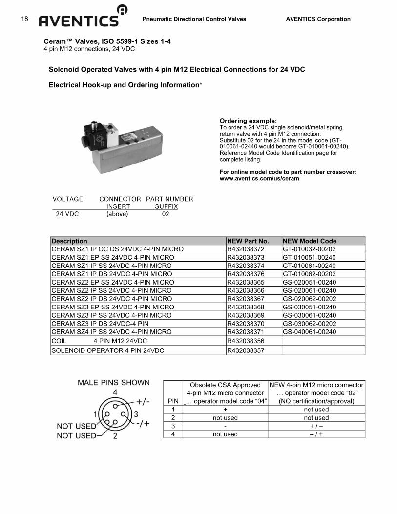
Ceram™ Valves, ISO 5599-1 Sizes 1-4 4 pin M12 connections, 24 VDC
Solenoid Operated Valves with 4 pin M12 Electrical Connections for 24 VDC Electrical Hook-up and Ordering Information*
Obsolete CSA Approved NEW 4-pin M12 micro connector 4-pin M12 micro connector … operator model code “02”
PIN … operator model code “04” (NO certification/approval) 1 + not used 2 not used not used 3 - + / – 4 not used – / +
Description NEW Part No. NEW Model Code CERAM SZ1 IP OC DS 24VDC 4-PIN MICRO R432038372 GT-010032-00202 CERAM SZ1 EP SS 24VDC 4-PIN MICRO R432038373 GT-010051-00240 CERAM SZ1 IP SS 24VDC 4-PIN MICRO R432038374 GT-010061-00240 CERAM SZ1 IP DS 24VDC 4-PIN MICRO R432038376 GT-010062-00202 CERAM SZ2 EP SS 24VDC 4-PIN MICRO R432038365 GS-020051-00240 CERAM SZ2 IP SS 24VDC 4-PIN MICRO R432038366 GS-020061-00240 CERAM SZ2 IP DS 24VDC 4-PIN MICRO R432038367 GS-020062-00202 CERAM SZ3 EP SS 24VDC 4-PIN MICRO R432038368 GS-030051-00240 CERAM SZ3 IP SS 24VDC 4-PIN MICRO R432038369 GS-030061-00240 CERAM SZ3 IP DS 24VDC-4 PIN R432038370 GS-030062-00202 CERAM SZ4 IP SS 24VDC 4-PIN MICRO R432038371 GS-040061-00240 COIL 4 PIN M12 24VDC R432038356 SOLENOID OPERATOR 4 PIN 24VDC R432038357
VOLTAGE CONNECTOR PART NUMBER INSERT SUFFIX 24 VDC (above) 02
Ordering example: To order a 24 VDC single solenoid/metal spring return valve with 4 pin M12 connection: Substitute 02 for the 24 in the model code (GT-010061-02440 would become GT-010061-00240). Reference Model Code Identification page for complete listing. For online model code to part number crossover: www.aventics.com/us/ceram

Pneumatic Directional Control Valves AVENTICS Corporation 19
Ceram™ Valves, ISO 5599-1 Sizes 1-4 CSA approved operator, single 4 or 5 pin connection For double solenoid valves
Solenoid Operated Valves with CSA Approved Operator Meeting ANSI B93.55 Electrical Connections (Brad Harrison® style)
Single 4 or 5 Pin Connection for Double Solenoid Valves, 2 or 3 Position
Ordering example: To order a 120VAC double solenoid, 2 position size 1 valve with single ANSI B93.55 5-pin connection: Substitute 07 for the 24 in the model code (GT-010061-02424 would become GT-010061-00707). Reference Model Code Identification page for complete listing. For online model code to part number crossover: www.aventics.com/us/ceram
Voltage Model Code Number of Pins Suffix
120 VAC 50/60 Hz 07 5 (mini)
24 VDC 08 5 (mini)
24 VDC 09 4 (micro)
Dimensions shown above are for Size 1 valve; for other sizes, add dimensions below to Size 1 valve body dimensions above. Electrical portion of valve does not change, regardless of valve size. Dimension Adders (inches)
Size Height Width
2 0.41 0.45
3 0.70 1.13
4 1.00 1.51
Length
0.50
2.22
3.30
5 PIN MALE CONNECTOR ANSI/B93.55M
INDICATOR LIGHT (RED)
MANUAL OVERRIDE

20 Pneumatic Directional Control Valves AVENTICS Corporation
Ceram™ Valves, ISO 5599-1 Sizes 1-4 Explosion proof and intrinsically safe solenoid valves
Explosion Proof Solenoid Valves for Hazardous Locations NEMA 7C & 7D & U.L. Class I-Groups C & D-Explosion Proof NEMA 8C & 8D & U.L. Class I-Groups C & D-Explosion Proof NEMA 9E, 9F & 9G & U.L. Class II-Groups E, F, G-Explosion Proof
Explosion Proof valves do not require solenoid connectors, as they come standard with 1/2” conduit housing and 18 inch wire leads.
Intrinsically Safe Solenoid Valves for Hazardous Locations (CSA approved) Classes I, II and III, DIV I Groups A, B, C, D, E, F and G
For use in low voltage (24VDC) Intrinsically Safe applications. NO OTHER VOLTAGE IS APPROVED.
Comes standard with non-lighted DIN solenoid connector.
Must be connected to an FM approved Zener Diode Barrier.* For dimensions, reference standard solenoid models. Maximum internally piloted valve pressure is 115 psi. Pressures to 150 psi can be used when external pilot is utilized and pilot pressure is limited to 115 psi. *FM Approved Barrier Manufacturer Stahl Incorporated—Woburn, MA Request AVENTICS Application Memo Issue#35 and ADV-300.ISSV for Intrinsically Safe Valve information and Stahl Barrier part numbers. Installation Information:
Ordering example: Model GT-010061-03940 = standard valve, same valve with intrinsically safe operator would be GT-010061-09040. Reference Model Code Identification page for complete listing. For online model code to part number crossover: www.aventics.com/us/ceram
Reference Model Code Identification page for model code information. For online model code to part number crossover: www.aventics.com/us/ceram
Dimensions **Operator does not overhang body assembly.
Size A B C E
IN mm IN mm IN mm IN mm IN mm 1 5.12 130.0 1.57 40.0 1.89 48.0 .31 8.0 1.52 38.5 2 5.82 147.8 2.03 51.6 2.30 58.4 .39 10.0 1.57 40.0 3 7.54 191.5 2.71 68.9 2.59 65.8 .41 10.4 1.62 41.3 4 8.62 218.9 3.09 78.5 2.89 73.4 .41 10.4 1.62 41.3
D
Size F G H K
IN mm IN mm IN mm IN mm IN mm 1 4.17 105.9 3.75 95.3 7.50 190.5 3.03 77.0 1.19 30.2 2 4.58 116.3 3.80 96.5 7.61 193.3 3.15 80.0 .90 22.9 3 4.87 123.7 3.86 98.0 7.71 195.8 3.25 82.6 .09 2.29 4 5.71 145.0 4.31 109.5 ** ** 3.25 82.6 ** **
J
Note:(1) Maximum non-hazardous voltage not to exceed 250V RMS.
(2) Connect per barrier manufacturers instructions (3) Connect per ISA RP 12.6 instructions (4) Maximum valve pressure 115 PSI. (5) Maximum inductance of solenoid operators when
mounted on valve body not to exceed 375 mH. (6) Solenoid operator for 3/2 way function normally
closed.
HAZARDOUS LOCATION CLASS 1, 2, AND 3. DIV. 1 GROUPS A, B, C, D, E, F, AND G V MAX. = 28V I MAX. = 115 mA Ci = 0uF Li = 0uH
SOLENOID VALVE
Pneumatic Directional Control Valves AVENTICS Corporation 21
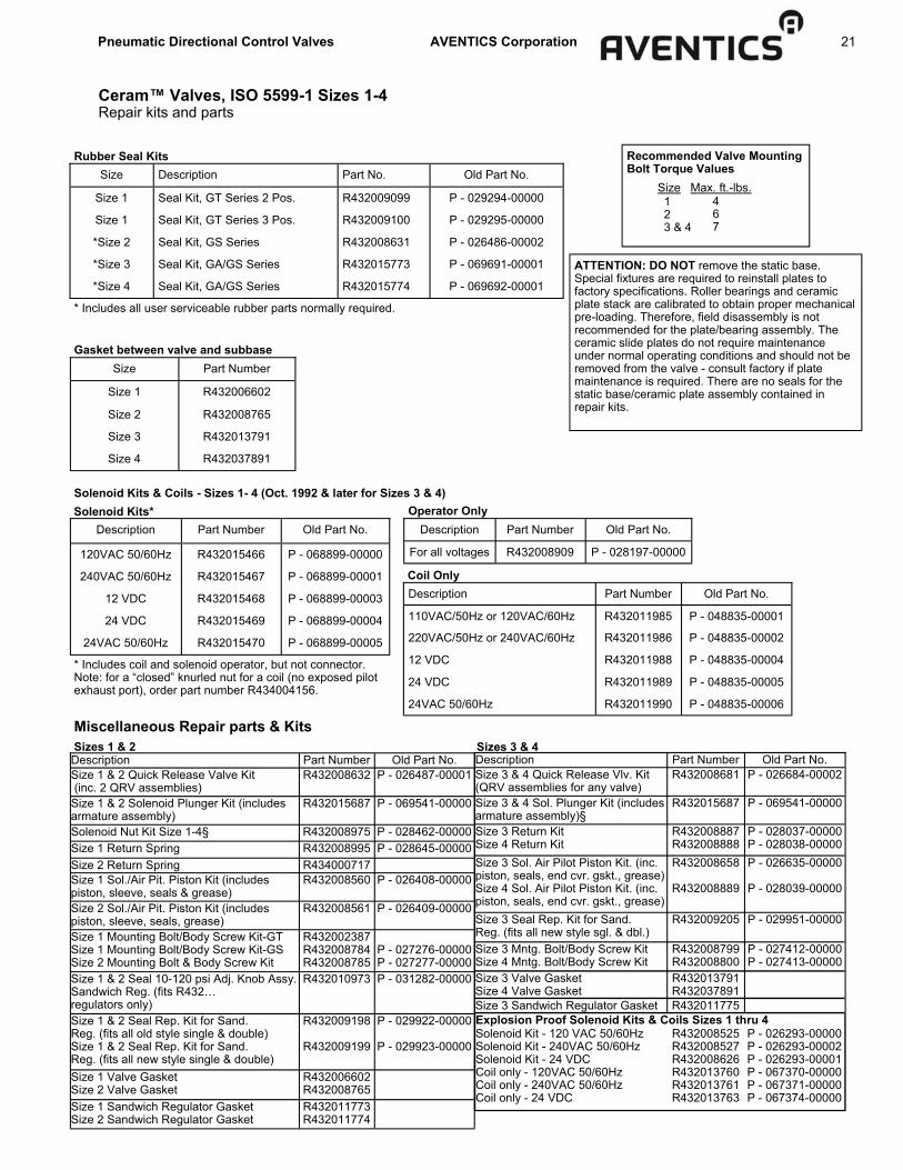
Ceram™ Valves, ISO 5599-1 Sizes 1-4 Repair kits and parts
Size Description Part No. Old Part No.
Size 1 Seal Kit, GT Series 2 Pos. R432009099 P - 029294-00000
Size 1 Seal Kit, GT Series 3 Pos. R432009100 P - 029295-00000
*Size 2 Seal Kit, GS Series R432008631 P - 026486-00002
*Size 3 Seal Kit, GA/GS Series R432015773 P - 069691-00001
*Size 4 Seal Kit, GA/GS Series R432015774 P - 069692-00001
ATTENTION: DO NOT remove the static base. Special fixtures are required to reinstall plates to factory specifications. Roller bearings and ceramic plate stack are calibrated to obtain proper mechanical pre-loading. Therefore, field disassembly is not recommended for the plate/bearing assembly. The ceramic slide plates do not require maintenance under normal operating conditions and should not be removed from the valve - consult factory if plate maintenance is required. There are no seals for the static base/ceramic plate assembly contained in repair kits.
* Includes all user serviceable rubber parts normally required.
Rubber Seal Kits
Size Part Number
Size 1 R432006602
Size 2 R432008765
Size 3 R432013791
Size 4 R432037891
Gasket between valve and subbase
Recommended Valve Mounting Bolt Torque Values Size Max. ft.-lbs.
1 2 3 & 4
4 6 7
Solenoid Kits & Coils - Sizes 1- 4 (Oct. 1992 & later for Sizes 3 & 4)
Description Part Number Old Part No.
120VAC 50/60Hz R432015466 P - 068899-00000
240VAC 50/60Hz R432015467 P - 068899-00001
12 VDC R432015468 P - 068899-00003
24 VDC R432015469 P - 068899-00004
24VAC 50/60Hz R432015470 P - 068899-00005
Solenoid Kits*
* Includes coil and solenoid operator, but not connector. Note: for a “closed” knurled nut for a coil (no exposed pilot exhaust port), order part number R434004156.
Description Part Number Old Part No.
For all voltages R432008909 P - 028197-00000
Operator Only
Description Part Number Old Part No.
110VAC/50Hz or 120VAC/60Hz R432011985 P - 048835-00001
220VAC/50Hz or 240VAC/60Hz R432011986 P - 048835-00002
12 VDC R432011988 P - 048835-00004
24 VDC R432011989 P - 048835-00005
24VAC 50/60Hz R432011990 P - 048835-00006
Coil Only
Description Part Number Old Part No. Size 1 & 2 Quick Release Valve Kit (inc. 2 QRV assemblies)
R432008632 P - 026487-00001
Size 1 & 2 Solenoid Plunger Kit (includes armature assembly)
R432015687 P - 069541-00000
Solenoid Nut Kit Size 1-4§ R432008975 P - 028462-00000 Size 1 Return Spring R432008995 P - 028645-00000 Size 2 Return Spring R434000717 Size 1 Sol./Air Pit. Piston Kit (includes piston, sleeve, seals & grease)
R432008560 P - 026408-00000
Size 2 Sol./Air Pit. Piston Kit (includes piston, sleeve, seals, grease)
R432008561 P - 026409-00000
Size 1 Mounting Bolt/Body Screw Kit-GT Size 1 Mounting Bolt/Body Screw Kit-GS Size 2 Mounting Bolt & Body Screw Kit
R432002387 R432008784 R432008785
P - 027276-00000 P - 027277-00000
Size 1 & 2 Seal 10-120 psi Adj. Knob Assy. Sandwich Reg. (fits R432… regulators only)
R432010973 P - 031282-00000
Size 1 & 2 Seal Rep. Kit for Sand. Reg. (fits all old style single & double) Size 1 & 2 Seal Rep. Kit for Sand. Reg. (fits all new style single & double)
R432009198
R432009199
P - 029922-00000
P - 029923-00000
Size 1 Valve Gasket Size 2 Valve Gasket
R432006602 R432008765
Size 1 Sandwich Regulator Gasket Size 2 Sandwich Regulator Gasket
R432011773 R432011774
Miscellaneous Repair parts & Kits
Description Part Number Old Part No. Size 3 & 4 Quick Release Vlv. Kit (QRV assemblies for any valve)
R432008681 P - 026684-00002
Size 3 & 4 Sol. Plunger Kit (includes armature assembly)§
R432015687 P - 069541-00000
Size 3 Return Kit Size 4 Return Kit
R432008887 R432008888
P - 028037-00000 P - 028038-00000
Size 3 Sol. Air Pilot Piston Kit. (inc. piston, seals, end cvr. gskt., grease) Size 4 Sol. Air Pilot Piston Kit. (inc. piston, seals, end cvr. gskt., grease)
R432008658
R432008889
P - 026635-00000
P - 028039-00000
Size 3 Seal Rep. Kit for Sand. Reg. (fits all new style sgl. & dbl.)
R432009205 P - 029951-00000
Size 3 Mntg. Bolt/Body Screw Kit Size 4 Mntg. Bolt/Body Screw Kit
R432008799 R432008800
P - 027412-00000 P - 027413-00000
Solenoid Kit - 120 VAC 50/60Hz Solenoid Kit - 240VAC 50/60Hz Solenoid Kit - 24 VDC Coil only - 120VAC 50/60Hz Coil only - 240VAC 50/60Hz Coil only - 24 VDC
R432008525 R432008527 R432008626 R432013760 R432013761 R432013763
P - 026293-00000 P - 026293-00002 P - 026293-00001 P - 067370-00000 P - 067371-00000 P - 067374-00000
Explosion Proof Solenoid Kits & Coils Sizes 1 thru 4
Size 3 Valve Gasket Size 4 Valve Gasket
R432013791 R432037891
Size 3 Sandwich Regulator Gasket R432011775
Sizes 1 & 2 Sizes 3 & 4

22 Pneumatic Directional Control Valves AVENTICS Corporation
Manifold Station Segment Part No.* R432037640 - 1/4” NPTF (side), 3/8” NPTF (bottom) R432037639 - 1/4 BSPP (side), 3/8 BSPP (bottom) Left & Right End Plate Kit Part No.* R432039422 - 3/8” NPTF R432041042 - 3/8 BSPP Port Plug, 3/8” NPTF: Part No. R431009434 Pressure Separation Disc Part No.** R432038306
Ceram™ Valves, ISO 5599-1 Sizes 1-4 Subbases and manifolds, Size 1 ISO SIZE 1 SUBBASES
Single Subbase (side ported) 1/4” or 3/8” NPT ports
Part No. R432031844 - Port Size 1/4” R432036353 - Port Size 3/8” (shown) 1825503143 - Port Size 1/4” BSPP R432036352 - Port Size 3/8” BSPP
*Includes gaskets and all hardware ** Includes 1 disc for multiple pressure zone
End and Bottom Ported Manifolds 1/4” NPT and 3/8” NPT delivery ports
Size A 1 B 1 C 1 D 1 E F G H J K L M N P Q R S T U 1 1/4 3/8 3/8 none 23 18 15.5 30 20 37.5 60.6 10.5 25 45 18 25 13.3 14.7 15
Size V W X Y Z AA AB AC AD AE AF AG AH AJ AK AL AM AN AP 1 150.5 135 102.5 66 50.3 27.3 24 18.5 57.5 18 23.8 11.8 none 8.3 5.8 none 12 5.5 8.5
1AVAILABLE IN G (BSPP) OR NPT THREADS ALL DIMENSIONS IN MM
NOTE: Not intended for use with Air Pilot valves. For manifolds for Air Pilot Valves, see page 32.
ISO SIZE 1 MANIFOLDS

Pneumatic Directional Control Valves AVENTICS Corporation 23
Ceram™ Valves, ISO 5599-1 Sizes 1-4 Manifold accessories, Size 1
Dual Sandwich Regulator (Ports 2 & 4) Both delivery port pressures are adjustable individually. Ideal for applications within a manifold where independent regulation of two supply pressures is required; no external pilot supply is required if minimum pilot pressure is available. Lip seal opens when down- stream pressure is >30 psi than upstream pressure to allow reverse flow. With locking adjustment knobs at "Control 12" for port 2 and "Control 14" end for port 4. Kit includes regulator (1), gasket (1), screws (4) and gauges (2). Part No. 0821302051 (10-120 psi) Dimensions: Height: 1.77" (45mm) Max. Overall Length: 11.50" (292mm)
Optional design (w/o gauge): (1/8" NPT gauge ports) R432015497 (5-60 psi) R432015498 (3-30 psi)
Single Sandwich Regulator Ideal for applications within a manifold where a particular pressure is required for one or more valves. Our regulator controls inlet pressure through to each cylinder port or delivery port pressures independently. A relieving type, the knob will also lock into a given position. Kit includes regulator (1), gasket (1), screws (4) and gauge (1). Port Part (10-120 psi) Regulation Number
1 0821302048
2 0821302054
4 0821302057
Dimensions: Height: 1.77" (45mm) Max. Overall Length: 7.80" (198mm) Optional design (w/o gauge, 1/8" NPT gauge port): R432009189 (Port 1, 5-60 psi) R432009190 (Port 1, 3-30 psi)
SIZE 1 ACCESSORIES Sandwich Flow Controls (Meter Out Ports 5 & 3) Our flow controls sandwich between the valve and subbase eliminating the need for addition piping and external controls for both working ports. Adjustment is with a knob on each side thread, along with our two stage needle design ensures excel-lent control. Kit includes flow control (1), gasket (1), and screws (4).
Part No. 0821201023 Dimensions Height: .98” (25mm) Maximum Overall Length: 3.15” (80mm)
Maintenance Plate Mounts between valve and sub-base. Used when servicing individual valves in a manifold system, or replacing a cylinder while the rest of the system is still operating. Two positions, can be locked with a cotter pin: 0. Maintenance position, flow is minimal and valve is isolated§; 1. Open position, normal operation - full flow in the system. § The low flow in the maintenance position allows slow pressurizing when the valve is returned to service. This low flow also requires the removal of trapped downstream pressure before removing or servicing these same components. CAUTION: Before service or removal of any components, all trapped pressure must be released. Vertically mounted cylinders, gravity and mechanically loaded actuators must be blocked/disable to avoid injury or system damage. Install blanking station segment kit if this minimal flow is undesirable when the valve is not present. Material: Aluminum, black anodized. Pressure range: Vacuum to 150 psi. dim= IN (mm)
ISO Part Number A1 A2 B C 1 580 159 000 0 2.76 (70) 3.35 (85) 1.57 (40) 0.98 (25)

24 Pneumatic Directional Control Valves AVENTICS Corporation
Ceram™ Valves, ISO 5599-1 Sizes 1-4 Manifold accessories, Size 1
ACCESSORIES (continued) SIZE 1 Sandwich Auxiliary Pressure Block (Port 1) The separate pressure block allows for more than two pressures to be provided to a manifold of valves. This unit sandwiches between the valve and base. Pressure to the balance of the manifold is isolated. Kit includes plate (1), gasket (1), screws (4). Part No. R432015767* Part No. R432015768* (Allows 3 or more pressures to be applied to the same manifold assembly. See manifold assembly page.) R432015767: auxiliary pressure supply blocked from manifold base port 1 channel R432015768: auxiliary pressure supply open to valve AND mani-fold base port 1 channel
1/4”-18 NPT INLET
Dimensions Height 1.19” (30.2mm) Maximum Overall Length: 3.45” (87.6mm)
SIZE 1 Blanking Plate Kit Allow for valve to be added later. Can be removed to add valve to existing manifold. Kit includes plate (1), gasket (1), screws (4). Shown on 1/4” base. Part No. 5801870000
ISO 5599-1 TRANSITION PLATE KIT ISO Size 1 to ISO Size 2 Dimensions: 5.6” x 1.4” x 3.2” Part No - R432037658 ISO Size 1 to ISO Size 3 Dimensions: 6.4” x 2.0” x 3.9” Part No - R432037659

Pneumatic Directional Control Valves AVENTICS Corporation 25
Single Subbase (side ported) 3/8” or 1/2” NPT ports
Ceram™ Valves, ISO 5599-1 Sizes 1-4 Subbases and manifolds, Size 2
Silencers: R432012058 Silencer, 3/8” NPT R432011952 Silencer, 1/2” NPT R432012059 Silencer, 3/4” NPT
Size A 1 B 1 C 1 D 1 E F G H J K L M N P Q R S T U 2 1/2 3/4 1/2 3/8 39 39 60 41.5 38 42.5 79.7 53 32 59.5 25 29.5 18 24.8 53
Size V W X Y Z AA AB AC AD AE AF AG AH AJ AK AL AM AN AP 2 162.5 143 119.6 66 63 26.1 29 23 73.5 20 39.5 19 11 9.1 6.6 8.2 21 6.3 9.3
*Includes gaskets and all hardware ** Includes 1 disc for multiple pressure zone
NOTE: Not intended for use with Air Pilot valves. For manifolds for Air Pilot Valves, see page 33.
Part No. R432036356 - Port Size 1/2” NPT R432031845 - Port Size 3/8” NPT (shown) 1825503146 - Port Size 3/8” BSPP R432036355 - Port Size 1/2” BSPP
ISO SIZE 2 SUBBASES
ISO SIZE 2 MANIFOLDS
Manifold Station Segment Part No.* R432037642 - 1/2” NPTF (side), 1/2” NPTF (bottom) R432037641 - 1/2 BSPP (side), 1/2 BSPP (bottom) Left & Right End Plate Kit* R432039423 - 1/2” NPTF R432041043 - 1/2 BSPP Port Plug, 1/2” NPTF: Part No. R432027755 Pressure Separation Disc Part No.** R432037662
End and Bottom Ported Manifolds 1/2” NPT and 1/2” NPT delivery ports

26 Pneumatic Directional Control Valves AVENTICS Corporation
Ceram™ Valves, ISO 5599-1 Sizes 1-4 Manifold accessories, Size 2
Dual Sandwich Regulator (Ports 2 & 4) Our pressure regulators sandwich between the valve and subbase eliminating the need for additional piping. Ideal for applications within a manifold where independent regulation of two supply pressures is required; no external pilot supply is required if minimum pilot pressure is available. Lip seal opens when downstream pressure is >30 psi than upstream pressure to allow reverse flow. With locking adjustment knobs at "Control 12" for port 2 and "Control 14" end for port 4. Kit includes regulator (1), gasket (1), and screws (4) Part No. R422103094 (10-120 psi) Dimensions: Height: 2.00” (50.9mm) Max Overall Length: 15.29” (388.3mm) Optional design (w/o gauge): (1/8” NPT gauge ports) R432015495 (5-60 psi)
Sandwich Flow Controls (Meter Out Ports 3 & 5)
Our flow controls sandwich between the valve and subbase eliminating the need for additional piping and external controls for both working ports. Adjustment is with a knob on each side. A fine thread, along with our two stage needle design assures excellent control. Kit includes speed control (1), gasket (1), and screws (4), Part No. 0821201024 Dimensions Height: 0.98” (25mm) Maximum Overall Length: 4.02” (102mm)
ISO SIZE 2 ACCESSORIES ISO SIZE 2 ACCESSORIES
Single Sandwich Regulator Ideal for applications within a manifold where a particular pressure is required for one or more valves. Our regulator controls inlet pressure through to each cylinder port or delivery port pressures independently. A relieving type, the knob will also lock into a given position. Kit includes regulator (1), gasket (1), and screws (4)
Port Regulation
Part Number
(10-120 psi)
1 R422103092
2 R422103093
Dimensions: Height: 2.00” (50.9mm) Max Overall Length: 9.01” (228.9mm) Optional design (w/o gauge, 1/8” NPT gauge port): R432009192 (Port 1, 5-60 psi) R432030015 (Port 1, 3-30 psi)
Maintenance Plate (Size 1, 2, 3) Mounts between valve and sub-base. Used when servicing individual valves in a manifold system, or replacing a cylinder while the rest of the system is still operating. Two positions, can be locked with a cotter pin: 0. Maintenance position, flow is minimal and valve is isolated§; 1. Open position, normal operation - full flow in the system. § The low flow in the maintenance position allows slow pressurizing when the valve is returned to service. This low flow also requires the removal of trapped downstream pressure before removing or servicing these same components. CAUTION: Before service or removal of any components, all trapped pressure must be released. Vertically mounted cylinders, gravity and mechanically loaded actuators must be blocked/disable to avoid injury or system damage. Install blanking station segment kit if this minimal flow is undesirable when the valve is not present. Material: Aluminum, black anodized. Pressure range: Vacuum to 150 psi. dim= IN (mm)
Pneumatic Directional Control Valves AVENTICS Corporation 27
Ceram™ Valves, ISO 5599-1 Sizes 1-4 Manifold accessories, Size 2
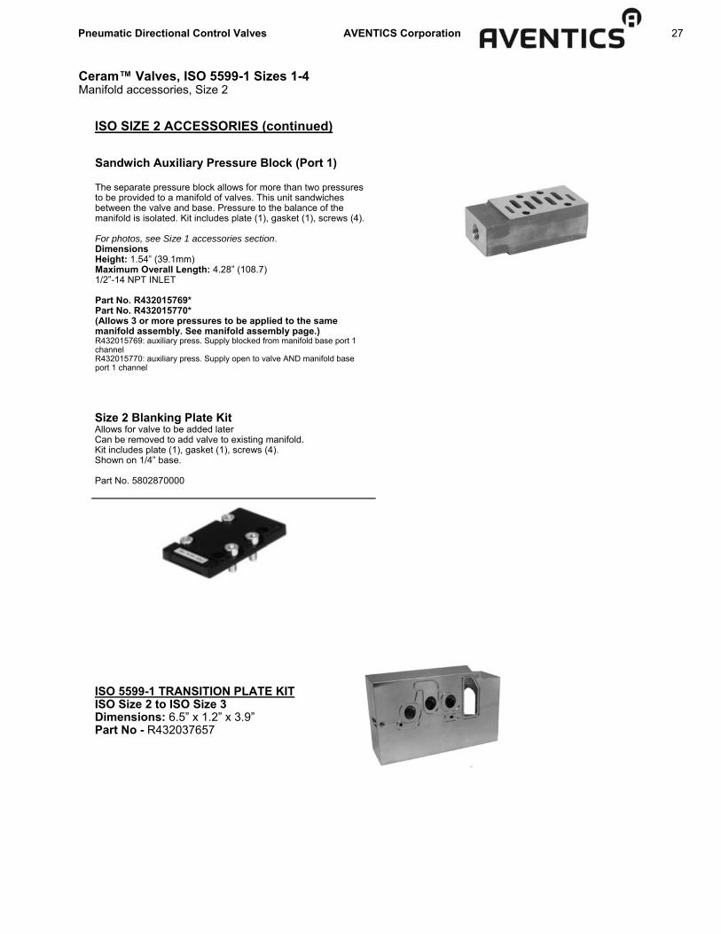
ISO SIZE 2 ACCESSORIES (continued)
Sandwich Auxiliary Pressure Block (Port 1) The separate pressure block allows for more than two pressures to be provided to a manifold of valves. This unit sandwiches between the valve and base. Pressure to the balance of the manifold is isolated. Kit includes plate (1), gasket (1), screws (4). For photos, see Size 1 accessories section. Dimensions Height: 1.54” (39.1mm) Maximum Overall Length: 4.28” (108.7) 1/2”-14 NPT INLET Part No. R432015769* Part No. R432015770* (Allows 3 or more pressures to be applied to the same manifold assembly. See manifold assembly page.) R432015769: auxiliary press. Supply blocked from manifold base port 1 channel R432015770: auxiliary press. Supply open to valve AND manifold base port 1 channel
Size 2 Blanking Plate Kit Allows for valve to be added later Can be removed to add valve to existing manifold. Kit includes plate (1), gasket (1), screws (4). Shown on 1/4” base. Part No. 5802870000
ISO 5599-1 TRANSITION PLATE KIT ISO Size 2 to ISO Size 3 Dimensions: 6.5” x 1.2” x 3.9” Part No - R432037657

28 Pneumatic Directional Control Valves AVENTICS Corporation
Ceram™ Valves, ISO 5599-1 Sizes 1-4 Subbases and manifold, Size 3
ISO SIZE 3 SUBBASES Single Subbase (side ported) 1/2" or 3/4" NPT ports
DIM A B C D E F G H J
IN 5.87 2.80 1.97 0.71 0.26 dia. 5.34 1.89 1.26 3.15
mm 149.0 71.0 50.0 18.0 6.6 dia. 136.0 48.0 32.0 80.0
DIM K P R S T U V W
IN 4.72 1.42 0.79 1.58 3.62 1.22 0.79 2.52
mm 120.0 36.0 20.0 40.1 92.0 31.0 20.0 64.0
Part No. R432015309 - port Size 3/4” NPT R432015308 - port Size 1/2” NPT 1825503149 - port Size 1/2” BSPP R432009166 - port Size 3/4” BSPP
M8 THREAD (4) PLS.
SIDE VIEW
SIDE VIEW (FROM OTHER SIDE)
3/4”-14 NPT or 1/2”-14 NPT
(5) PLS.
1/8”-27 NPT (2) PLS.
(PILOT PORTS)
Size A 1 B 1 C 1 D 1 E F G H J K L M N P Q R S T U 3 3/4 1 3/4 1/2 49 49 76 53 32 53 100 88 37 80 38 36 24.5 20.5 88
Size V W X Y Z AA AB AC AD AE AF AG AH AJ AK AL AM AN AP
3 183 164.7 99 72 73 30.5 28 22 96 22 46.3 25.1 11.2 6.8 6.8 15.8 22.5 6.3 9.3
Silencers 1/2" NPT Silencer, Part No. R432011952 3/4" NPT Silencer, Part No. R432012059
Manifold Station Segment Part No.* R432037644 - 3/4” NPTF (side), 3/4” NPTF (bottom) R432037643 - 3/4 BSPP (side), 3/4 BSPP (bottom) Left & Right End Plate Kit* R432039657 - 1” NPTF R432041044 - 1 BSPP Port Plug, 1” NPTF: Part No. R432027756 Pressure Separation Disc Part No.** R432037663
*Includes gaskets and all hardware ** Includes 1 disc for multiple pressure zone
Metric manifolds and subbases are available from online catalog at www.aventics.com/pneumatics-catalog
NOTE: Not intended for use with Air Pilot valves. For manifolds for Air Pilot Valves, see page 34.
ISO SIZE 3 MANIFOLDS
End and Bottom Ported Manifolds 3/4” NPT and 1” NPT delivery ports

Pneumatic Directional Control Valves AVENTICS Corporation 29
ISO SIZE 3 ACCESSORIES Dual Sandwich Regulator (Ports 2 & 4) Our pressure regulators sandwich between the valve and subbase eliminating the need for additional piping. Ideal for applications within a manifold where independent regulation of two supply pressures is required; no external pilot supply is required if minimum pilot pressure is available. Supplying ports 2 and 4, free flow reverse check valves allow flow in both directions. With locking adjustment knobs at "Control 12" for port 2 and "Control 14" end for port 4. Kit includes regulator (1), gasket (1), and screws (4)
Silencers 1/2" NPT Silencer, Part No. R432011952 3/4" NPT Silencer, Part No. R432012059 Metric manifolds and subbases are available from online catalog at www.aventics.com/pneumatics-catalog
Ceram™ Valves, ISO 5599-1 Sizes 1-4 Subbases and manifold accessories, Size 3
Sandwich Flow Controls (Meter Out Ports 3 & 5) Our flow controls sandwich between the valve and subbase eliminating the need for additional piping and external controls for both working ports. Adjustment is via a screw on each side, assuring excellent control. Kit includes speed control (1), gasket (1) and screws (4). Part No. R432008895 Dimensions Height: 0.94" (23.9mm) Maximum Overall Length: 6.44" (163.6mm) Width: 2.50" (63.5mm) (Cannot be combined with sandwich regulator.)
ISO SIZE 3 ACCESSORIES Single Sandwich Regulator Ideal for applications within a manifold where a particular pressure is required for one or more valves. Our regulator controls inlet pressure through to each cylinder port or delivery port pressures independently. A relieving type, the knob will also lock into a given position. Kit includes regulator (1), gasket (1), and screws (4)
Port Regulation
Part Number
(10-120 psi)
1 R422103096
2 R422103097
Dimensions: Height: 2.76” (70mm) Max Overall Length: 11.37” (288.8mm) Optional design (w/o gauge, 1/8” NPT gauge port): R432009194 (Port 1, 5-60 psi) R432009195 (Port 1, 3-30 psi)
Part No. R422103098 (10-120 psi) Dimensions: Height: 2.76” (70mm) Max. Overall Length: 18.46” (469mm) Optional design (w/o gauge): (1/8” NPT gauge port) R432009411 (5-60 psi)
Maintenance Plate Mounts between valve and sub-base. Used when servicing individual valves in a manifold system, or replacing a cylinder while the rest of the system is still operating. Two positions, can be locked with a cotter pin: 0. Maintenance position, flow is minimal and valve is isolated§; 1. Open position, normal operation - full flow in the system. § The low flow in the maintenance position allows slow pressurizing when the valve is returned to service. This low flow also requires the removal of trapped downstream pressure before removing or servicing these same components. CAUTION: Before service or removal of any components, all trapped pressure must be released. Vertically mounted cylinders, gravity and mechanically loaded actuators must be blocked/disable to avoid injury or system damage. Install blanking station segment kit if this minimal flow is undesirable when the valve is not present. Material: Aluminum, black anodized. Pressure range: Vacuum to 150 psi. dim= IN (mm)
ISO Part Number A1 A2 B C 3 580 359 000 0 4.65 (118) 5.39 (137) 2.56 (65) 1.42 (36)
Blanking Plate Kit - Size 3 Allow for valve to be added later. Kit includes plate, gasket and screws. Part No. 5803870000

30 Pneumatic Directional Control Valves AVENTICS Corporation
Ceram™ Valves, ISO 5599-1 Sizes 1-4 Subbases, Size 4
DIM C D E F G H J K L M N P Q R S
IN 8.46 6.30 3.23 2.17 2.28 1.18 2.20 .59 .47 2.13 1.10 2.05 5.59 .31 .35
mm 215 160 82 55 58 30 56 15 12 54 28 52 142 8 9
* Includes gaskets and all hardware
ISO SIZE 4 MANIFOLDS Manifold Station Segment Part No.* R432039362 - 3/4” NPTF (bottom) 8985041422- 3/4 BSPP (bottom) End Plate Kit Part No.* R432039363 - 1” NPTF 8985041442 - 1 BSPP

Pneumatic Directional Control Valves AVENTICS Corporation 31
Ceram™ Valves, ISO 5599-1 Sizes 1-4 Subbases and manifold accessories, Size 4
ISO SIZE 4 SUBBASES ISO SIZE 4 ACCESSORIES
Sandwich Flow Controls (Meter Out Ports 3 & 5) Our flow controls sandwich between the valve and subbase eliminating the need for additional piping and external controls for both working ports. Adjustment is via a screw on each side, assuring excellent control. Kit includes speed control (1), gasket (1), and screws (4).
Dimensions Height: 0.94” Maximum Overall Length: 7.75” Width: 3.00”
Part No. R432009004
Single Subbase (side ported) 1” NPT ports TOP VIEW
DIM A B C D E F G H J IN 7.32 3.15 2.44 .71 .26 6.77 2.28 1.97 4.17
mm 186.0 80.0 62.0 18.0 6.5 172.0 58.0 50.0 106.0
DIM K M N P R S T
IN 1.97 4.57 1.85 1.10 3.15 1.58 .33
mm 50.0 116.0 47.0 28.0 80.0 40.0 8.5
Metric manifolds and subbases are available from online catalog.
Part No. R432031847 - Port Size 1”
Blanking Plate Kit - Size 4 Allows for valve to be added later. Kit includes plate, Gasket and screws. Part No. 5804870000 R432011952 Silencer, 1/2” NPT R432012059 Silencer, 3/4” NPT

32 Pneumatic Directional Control Valves AVENTICS Corporation
End Ported Manifolds 1/4” NPT delivery ports
Part Number R432015314* - Manifold Station Segment** Part Number R432015316* - End Plates (Includes both ends)**
*Manifold gaskets included. **All hardware is included.
DIM NUMBER OF VALVES
2 3 4 5 6 7 8 IN mm IN mm IN mm IN mm IN mm IN mm IN mm
5.91 150.0 7.60 193.0 9.29 236.0 10.9 322.0 12.6 322.0 14.37 365.0 16.0 408.0 B 5.39 136.8 7.08 179.8 8.77 222.8 10.4 265.8 12.1 308.8 13.85 351.8 15.5 394.8
A
Air Pilot Valve Manifolds Size 1 - 3
END PORTED MANIFOLDS STATION SEGMENT (R432015314) Each station segment kit comes complete with pipe plugs (to block unused delivery ports), fastening hardware, and a gasket. The gasket is placed between each station segment. The standard sealing gasket (A GASKET, PART NUMBER - R432008985) including has windows open for ports 1,3, & 5 END PLATE KITS (R432015316) Consists of two end plates complete with pipe plugs (to block unused supple and exhaust ports), fastening hardware, and the standard sealing gasket (A GASKET, Part Number - R432008985) MANIFOLD WITH TWO DIFFERENT SUPPLY PRESSURES Different supply pressures can be provided by placing blocking gasket B (1821015043) between two of the station segments to divide the two different pressures.
BLOCKING GASKET A R432008985
BLOCKING GASKET B 1821015043
ISO SIZE 1 MANIFOLDS

Pneumatic Directional Control Valves AVENTICS Corporation 33
ISO SIZE 2 MANIFOLDS End Ported Manifold 1/2” NPT delivery port
DIM C D E F G H J K M N
IN 3.15 2.82 .17R 4.96 7.09 .79 .79 2.52 2.68 .67
mm 80.0 71.6 R4.3 126.0 104.0 20.0 20.0 64.0 68.0 17.0
DIM P R S T U V W X Y
IN 1.02 1.02 2.68 2.20 2.68 1.42 1.18 2.44 2.44
mm 26.0 26.0 68.0 56.0 68.0 36.0 30.0 62.0 62.0
DIM NUMBER OF VALVES
2 3 4 5 6 7 8
IN mm IN mm IN mm IN mm IN mm IN mm IN mm
7.56 192.0 9.76 248.0 11.97 304.0 14.17 360.0 16.38 416.0 18.58 472.0 20.79 528.0
B 6.01 168.0 8.82 224.0 11.00 279.4 13.23 336.0 15.43 392.0 17.64 448.0 19.84 504.0
A
*Manifold gaskets included. **All hardware is included.
Part Number R432015318* - Manifold Station Segment Part Number R432015319 - End Plates (Includes both ends)**
Air Pilot Valve Manifolds Size 1 - 3
AVENTICS END PORTED MANIFOLDS STATION SEGMENT Each station segment kit comes complete with hardware, seals, and a sealing plate. The sealing plate is placed between each segment to ensure sealing between the Buna N gaskets. The standard sealing plate (PLATE A) included has windows open for ports 1,3, & 5. END PLATE KITS Consists of two end plates complete with hardware and seals. Pressure is blocked on Size II end plates with 3/4” pipe plugs (included). MANIFOLD WITH TWO DIFFERENT SUPPLY PRESSURES On size 2 manifolds, place plate B where the pressure division is desired and remove pipe plugs from the end cover.
PLATE A 1, 3, & 5 Open R432015343
PLATE B All ports blocked R432015342
PLATE C 1, 3, 5, 12 & 14 Open R432015344

34 Pneumatic Directional Control Valves AVENTICS Corporation
ISO SIZE 3 MANIFOLDS 1/2” or 3/4” NPT Delivery Ports
Part No. R432015491 - Manifold Station Segment (1/2” NPT) Part No. R432015490 for 3/4” NPT Delivery Ports Part No. R432015492 - End Plates (includes both ends)
DIM NUMBER OF VALVES
2 3 4 5 6 7 8
IN mm IN mm IN mm IN mm IN mm IN mm IN mm
8.10 205.7 10.90 276.9 13.70 348.0 16.50 419.1 19.30 490.2 22.10 561.3 24.90 632.5
B 6.38 162.1 9.18 233.2 11.98 304.3 14.78 375.4 17.58 446.5 20.38 517.7 23.18 588.8
A
Air Pilot Valve Manifolds Size 1 - 3

Pneumatic Directional Control Valves AVENTICS Corporation 35
Ceram™ Valves, ISO 5599/1 Sizes 1-4 Pressure gauges for sandwich regulators
Figure 1 Figure 2
Compressed Air Connection Nominal diameter Application Display
range Operating pressure Scale value Part No.
Size Location
R 1/8 Bottom 50 mm 0 - 10 bar 0 - 12 bar 0 / 12 bar 0.2 bar 8901703200 1
G 1/8 Back 40 mm 0 - 8 bar 0 - 10 bar 0 / 10 bar 0.2 bar R412003857 2
1/8” NPT Back 1.58” 0 - 150 psi 0 - 200 psi 0 / 200 psi 5 psi R412010064 2
Figure

36 Pneumatic Directional Control Valves AVENTICS Corporation
Ceram™ Valves, ISO 5599/1 Sizes 1-4 Internal to external pilot field conversions, Sizes 1 and 2
GT Series Size 1 and GS Series Size 2 Valves ** Solenoid Valve Internal To External Pilot Field Conversion** CAUTION: Air Supply should be removed before modification. EXTERNALLY PILOTED VALVES ARE AVAILABLE DIRECTLY FROM THE FACTORY. See model explanation on page 7 as well as individual notes on pages 8-14 under standard valve models for ordering instructions. The following procedure should be used to convert a solenoid valve from internal pilot pressure operation. All valves come from the factory internally piloted. External pilot function is required if the supply pressure is below the minimum pilot pressure of 29 psi (2-position valves; 44 psi for 3-position models) or if the customer is using vacuum for supply pressure.
SIZE 1 GT SERIES VALVE EXTERNAL PILOT CONVERSION
SIZE 2 GS SERIES VALVE EXTERNAL PILOT CONVERSION
For external pilot conversion, remove gasket from valve body as shown in Figure 1 and 2. Flip gasket end-to-end so that Tab “A” will cover the internal pilot port shown in Figure 1. Remove Tab “E” shown in Figure 2. Mount valve to base. Apply a minimum of 29 psi (2-position valves) or 44 psi (3-position valves) to Port 14. Port 14 will provide pilot pressure to all solenoids regardless of single or double configuration. NOTE: Port 12 does not need to be plugged. Port 12 is used only on Double Air Pilot models. Note: This page does not apply to air piloted/air spring return valves.
Pneumatic Directional Control Valves AVENTICS Corporation 37
Ceram™ Valves, ISO 5599/1 Sizes 1-4 Internal to external pilot field conversion, Sizes 3 and 4
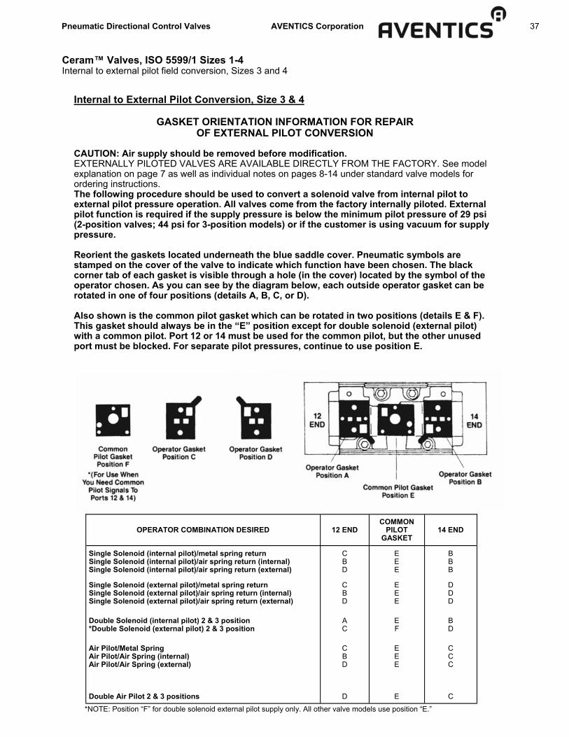
Internal to External Pilot Conversion, Size 3 & 4
GASKET ORIENTATION INFORMATION FOR REPAIR OF EXTERNAL PILOT CONVERSION
CAUTION: Air supply should be removed before modification. EXTERNALLY PILOTED VALVES ARE AVAILABLE DIRECTLY FROM THE FACTORY. See model explanation on page 7 as well as individual notes on pages 8-14 under standard valve models for ordering instructions. The following procedure should be used to convert a solenoid valve from internal pilot to external pilot pressure operation. All valves come from the factory internally piloted. External pilot function is required if the supply pressure is below the minimum pilot pressure of 29 psi (2-position valves; 44 psi for 3-position models) or if the customer is using vacuum for supply pressure. Reorient the gaskets located underneath the blue saddle cover. Pneumatic symbols are stamped on the cover of the valve to indicate which function have been chosen. The black corner tab of each gasket is visible through a hole (in the cover) located by the symbol of the operator chosen. As you can see by the diagram below, each outside operator gasket can be rotated in one of four positions (details A, B, C, or D). Also shown is the common pilot gasket which can be rotated in two positions (details E & F). This gasket should always be in the “E” position except for double solenoid (external pilot) with a common pilot. Port 12 or 14 must be used for the common pilot, but the other unused port must be blocked. For separate pilot pressures, continue to use position E.
GASKET POSITION CHART
OPERATOR COMBINATION DESIRED 12 END COMMON
PILOT GASKET
14 END
Single Solenoid (internal pilot)/metal spring return Single Solenoid (internal pilot)/air spring return (internal) Single Solenoid (internal pilot)/air spring return (external)
C B D
E E E
B B B
Single Solenoid (external pilot)/metal spring return Single Solenoid (external pilot)/air spring return (internal) Single Solenoid (external pilot)/air spring return (external)
C B D
E E E
D D D
Double Solenoid (internal pilot) 2 & 3 position *Double Solenoid (external pilot) 2 & 3 position
A C
E F
B D
Air Pilot/Metal Spring Air Pilot/Air Spring (internal) Air Pilot/Air Spring (external)
C B D
E E E
C C C
Double Air Pilot 2 & 3 positions D E C
*NOTE: Position “F” for double solenoid external pilot supply only. All other valve models use position “E.”

38 Pneumatic Directional Control Valves AVENTICS Corporation
Port Marking 1=
2 & 4= 3 & 5=
12 & 14=
Common Exhaust Port Delivery (Cylinder) Ports Supply Pressures External Pilot Ports
Ceram™ Valves, ISO 5599/1 Sizes 1-4 Piping procedures
Dual Pressure Valve Conversion Instructions (Size 1 & 2) Please note that the supply pressure in Port 5 must be at least 29 psi (for 2-position models) or 44 psi (for 3-position models). If minimum pressure is not met on port 5, external piloting must be used; see page 38 for directions. Size 1 & 2 CERAM Valves are designed for dual pressure applications. For this service “replumb” the subbase by using ports “3” and “5” for the two different supplies, and port “1” for a common exhaust. (Ports “2” and “4” are still the delivery ports.) Port “3” will supply port “2”, and port “5” will supply port “4”. After the subbase has been “replumbed”, remove the valve from the subbase and remove the bottom gasket as shown in Figure 1 and 2. Flip the gasket end-to-end so the internal pilot hole will be covered by the gasket as shown in Figure 3. remove tab “B” as shown in Figure 3. Remount valve to base.
Dual Pressure Valve Conversion Instructions (Sizes 3 & 4) Convert to external pilot according to instructions on previous page, then follow instructions at top right of this page.
Piping Instructions - All Sizes (1, 2, 2, 4) CAUTION: Air supply should be removed before modification. Normal Piping Procedure Use these connections if you have one supply pressure only. Single Pressure
Dual Pressure Piping Procedure 2 Position Valve Piping. (Do not use unless you must use 2 different supply pressures.)
Port Marking 1=
2 & 4= 3 & 5=
12 & 14=
Supply Pressure Delivery (Cylinder) Ports Exhaust Ports External Pilot Ports 3 Position Valve Piping. (Use
for supplied center or for 2 different supply pressure.)
SIZE 1 GT SERIES VALVE DUAL PRESSURE CONVERSION
SIZE 2 GS SERIES VALVE DUAL PRESSURE CONVERSION

Pneumatic Directional Control Valves AVENTICS Corporation 39
Series DO10-MR Miniature Pneumatic Valves Directional control, direct operated solenoid, 10mm body width
Version Configurations Working pressure Orifice size Ambient temperature Medium Max. flow (at 6 bar, with press. Drop of 1 bar) Exhaust flow Manual override Max. no. of cycles per min. Life expectancy Pneumatic ports Electrical protection class Voltages Voltage tolerance Coil insulation Switch (response) time Power consumption Materials: Housing Seals Springs
Direct operated solenoid 2/2 NC, 3/2 NC, 3/2 NO 0 to 102 psi (0 to 7 bar) 0.7 mm 23° to 122°F (-5° to +55°C) Compressed air 0.014Cv (14 NI/min) 0.022Cv (22 NI/min) Push type, non-locking 2,700 50 million cycles Single subbase, manifold IP65 (NEMA 4) 6, 12, 24VDC, other specials -5% to +10% F class standards 8 ms on 10 ms off 0.5 to 1.3 watts Nylon NBR 302 stainless steel
1 = Supply Port 2 = Outlet Port 3 = Exhaust Port
Normally closed NC 3/2 Normally open NO 3/2 Normally closed NC 2/2
De-Actuated Actuated De-Actuated Actuated De-Actuated Actuated

40 Pneumatic Directional Control Valves AVENTICS Corporation
Series DO10-MR Miniature Pneumatic Valves Directional control, direct operated solenoid, 10mm body width
Model Code/Ordering Options
MR10-__ __ __ - __
Type Voltage Electrical Connection Open Exhaust
1 = 2/2 NC 1 = 24 VDC 1 = 2-pin 90° Conn. with LED S = Standard (channeled exhaust)
20 = 3/2 NC 2 = 12 VDC 2 = Flying leads (300mm) E = Open exhaust (only NC types)
3 = 3/2 NO 3 = 24 VAC 3 = 2-pin 180° Conn. + LED
4 = 6 VDC 4 = 2-pin 90° Conn., no LED
5 = 24 VDC (0.5 watt)
5 = 2-pin 180° Conn., no LED
6 = 100mm cable + Molex male conn.*
7 = 100mm cable + MODU II conn.*
8 = 100mm cable + Molex female conn.*
9 = M3 threaded ports for inline use (no subbase needed) and open exhaust
Example: MR10-211-E = 10mm valve, 3/2 NC, 24VDC, 2-pin 90° connector with LED, open exhaust Note: Items highlighted in grey are standard, other options available upon request, contact Technical Support at the factory. *Molex male connector = Molex part number 51006-0200. Molex female connector = Molex part number 51065-0200. MODU II connector = Tyco part number 280358-0.
Part Number to Model Number Crossover for DO10-MR Valves Model Code Part No. Type Voltage Connector Figure
MR10-111-S R432033293 2/2 NC 24 VDC 90 + LED 1
MR10-112-S R432033292 2/2 NC 24 VDC 300 mm cable 2
MR10-121-S R432033291 2/2 NC 12 VDC 90 + LED 1
MR10-122-S R432033290 2/2 NC 12 VDC 300 mm cable 2
MR10-211-S R432033297 3/2 NC 24 VDC 90 + LED 1
MR10-212-S R432033296 3/2 NC 24 VDC 300 mm cable 2
MR10-221-S R432033295 3/2 NC 12 VDC 90 + LED 1
MR10-222-S R432033294 3/2 NC 12 VDC 300 mm cable 2
MR10-311-S R432033301 3/2 NO 24 VDC 90 + LED 1
MR10-312-S R432033300 3/2 NO 24 VDC 300 mm cable 2
MR10-321-S R432033299 3/2 NO 12 VDC 90 + LED 1
MR10-322-S R432033298 3/2 NO 12 VDC 300 mm cable 2
Note: Scope of delivery includes mounting hardware.

Pneumatic Directional Control Valves AVENTICS Corporation 41
Series DO10-MR Miniature Pneumatic Valves Directional control, direct operated solenoid, 10mm body width
Figure 1: 2-pin 90° Connector
Figure 2: Flying leads (300mm)
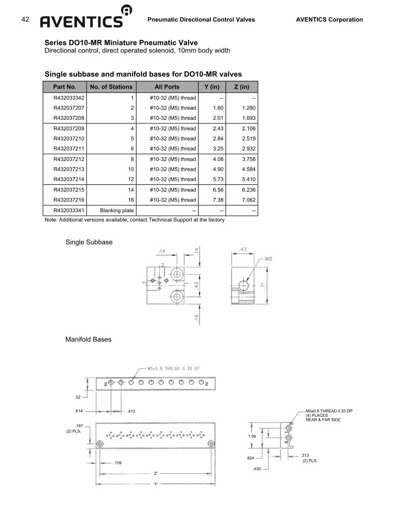
42 Pneumatic Directional Control Valves AVENTICS Corporation
Series DO10-MR Miniature Pneumatic Valve Directional control, direct operated solenoid, 10mm body width
Single subbase and manifold bases for DO10-MR valves Part No. No. of Stations All Ports Y (in) Z (in)
R432033342 1 #10-32 (M5) thread -- --
R432037207 2 #10-32 (M5) thread 1.60 1.280
R432037208 3 #10-32 (M5) thread 2.01 1.693
R432037209 4 #10-32 (M5) thread 2.43 2.106
R432037210 5 #10-32 (M5) thread 2.84 2.519
R432037211 6 #10-32 (M5) thread 3.25 2.932
R432037212 8 #10-32 (M5) thread 4.08 3.758
R432037213 10 #10-32 (M5) thread 4.90 4.584
R432037214 12 #10-32 (M5) thread 5.73 5.410
R432037215 14 #10-32 (M5) thread 6.56 6.236
R432037216 16 #10-32 (M5) thread 7.38 7.062
R432033341 Blanking plate -- -- --
Note: Additional versions available, contact Technical Support at the factory
Single Subbase
Manifold Bases
.159
.197
.614
.52
‘Z’
‘Y’
.413
(2) PLS.
.824
.430
1.06
.313
M5x0.8 THREAD 0.20 DP (4) PLACES NEAR & FAR SIDE
(2) PLS.

Pneumatic Directional Control Valves AVENTICS Corporation 43
Series DO10-MR Miniature Pneumatic Valves Directional control, direct operated solenoid, 10mm body width
Blanking plate for DO10-MR valves, Part no.
Part No. Cable Length
R432033338 300mm
R432033339 600mm
R432033340 1 meter
Connector Cables (for 2-pin connectors)

44 Pneumatic Directional Control Valves AVENTICS Corporation
Version Configurations Working pressure Orifice size Ambient temperature Medium Max. flow Exhaust flow Manual override Max. no. of cycles per min. Life expectancy Pneumatic ports Electrical protection class Voltages Voltage tolerance Coil insulation Switch (response) time Power consumption Materials: Housing Seals Springs
Direct operated solenoid 2/2 N/C, 2/2 NO, 3/2 NC, 3/2 NO See table 0.8mm, 1.1mm and 1.6mm 23° to 122°F (-5° to +50°C) Compressed air See table Push type, locking and non-locking 2,700 50 million cycles Single subbase, manifold IP65 (NEMA 4) w/ cables or connectors IP00 without cables/connectors 12 and 24VDC 24, 110 & 220 VAC 50/60Hz -5% to +10% F class standards 10 ms on 12 ms off See table Nylon NBR 302 stainless steel
Series DO15-MR Miniature Pneumatic Valves Directional control, direct operated solenoid, 15mm body width
Normally closed NC 3/2 Normally open NO 3/2
De-Actuated Actuated De-Actuated Actuated
Orifice Size
Working pressure psi (bar) for NC
Working pressure psi (bar) for NO
Max. Flow Cv (NI/min)*
Voltages VDC
Voltages VAC 50/60Hz
Power Watts (VDC)
Power VA (VAC)
0.8 mm 0 to 145 (0 to 10) - - 0.02 (20) 24 - - 1.0 - -
1.1 mm 0 to 145 (0 to 10) 0 to 102 (0 to 7) 0.03 (30) 12 & 24 24, 110 & 220 2.3 2.8 VA at starting 2.5 VA at speed
1.6 mm 0 to 102 (0 to 7) 0 to 73 (0 to 5) 0.05 (50) 12 & 24 24, 110 & 220 2.3 2.8 VA at starting 2.5 VA at speed
*at 6 bar, with pressure drop of 1 bar
1 = Supply Port 2 = Outlet Port 3 = Exhaust Port

Pneumatic Directional Control Valves AVENTICS Corporation 45
Series DO15-MR Miniature Pneumatic Valves Directional control, direct operated solenoid, 15mm body width
Model Code/Ordering Options MR15- __ __ __ - __ __ __
Type Voltage Electrical Connection
Orifice Dia. (mm)
Manual Override Open Exhaust
1 = 2/2 NC 1 = 24 VDC 0 = AMP Faston
A = 1.1 - 1.1 1 = Without man. override and M3
insert
S = Standard (channeled
exhaust)
2 = 3/2 NC 2 = 12 VDC 1 = 2-pin 90° Conn. with LED
B = 1.6 - 1.6 2 = Without man. override
E = Open exhaust (only
NC types
3 = 3/2 NO 3 = 24 VAC 50/60 Hz
2 = Flying leads (300mm)
C = 1.6 - 1.1 NO 3 = Without M3 insert
4 = 2/2 NO 6 = 110 VAC 50/60 Hz
3 = 2-pin 180° Conn. with LED
D = 0.8 - 1.1 NC 4 = With 2 pos. man. override
7 = 220 VAC 50/60 Hz
D = DIN 43650 Form C
5 = With push type man. override
8 = 24 VDC 1 watt
(0.8 size only)
9 = 24 VDC + Earth ground
Example: MR15-221-B4E = 15mm valve, 3/2 NC, 12 VDC, 2-pin 90° connector with LED, orifice diameter 1.6 - 1.6, with 2 position manual override, open exhaust Notes: Items highlighted in grey are standard, contact Technical Support at the factory. Scope of delivery includes mounting hardware.

46 Pneumatic Directional Control Valves AVENTICS Corporation
Series DO15-MR Miniature Pneumatic Valves Directional control, direct operated solenoid, 15mm body width
Model Code Part No. Type Voltage Connector Manual Override Figure
MR15-111-B4S R432033324 2/2 NC 24 VDC 90 + LED 2 position (locking) 1
MR15-111-B5S R432033306 2/2 NC 24 VDC 90 + LED Push type 1
MR15-112-B4S R432033323 2/2 NC 24 VDC 300 mm cable 2 position (locking) 2
MR15-112-B5S R432033305 2/2 NC 24 VDC 300 mm cable Push type 2
MR15-11D-B4S R432033325 2/2 NC 24 VDC DIN 2 position (locking) 3
MR15-11D-B5S R432033307 2/2 NC 24 VDC DIN Push type 3
MR15-121-B4S R432033321 2/2 NC 12 VDC 90 + LED 2 position (locking) 1
MR15-121-B5S R432033303 2/2 NC 12 VDC 90 + LED Push type 1
MR15-122-B4S R432033320 2/2 NC 12 VDC 300 mm cable 2 position (locking) 2
MR15-122-B5S R432033302 2/2 NC 12 VDC 300 mm cable Push type 2
MR15-12D-B4S R432033322 2/2 NC 12 VDC DIN 2 position (locking) 3
MR15-12D-B5S R432033304 2/2 NC 12 VDC DIN Push type 3
MR15-211-B4S R432033330 3/2 NC 24 VDC 90 + LED 2 position (locking) 1
MR15-211-B5S R432033312 3/2 NC 24 VDC 90 + LED Push type 1
MR15-212-B4S R432033329 3/2 NC 24 VDC 300 mm cable 2 position (locking) 2
MR15-212-B5S R432033311 3/2 NC 24 VDC 300 mm cable Push type 2
MR15-21D-B4S R432033331 3/2 NC 24 VDC DIN 2 position (locking) 3
MR15-21D-B5S R432033313 3/2 NC 24 VDC DIN Push type 3
MR15-221-B4S R432033327 3/2 NC 12 VDC 90 + LED 2 position (locking) 1
MR15-221-B5S R432033309 3/2 NC 12 VDC 90 + LED Push type 1
MR15-222-B4S R432033326 3/2 NC 12 VDC 300 mm cable 2 position (locking) 2
MR15-222-B5S R432033308 3/2 NC 12 VDC 300 mm cable Push type 2
MR15-22D-B4S R432033328 3/2 NC 12 VDC DIN 2 position (locking) 3
MR15-22D-B5S R432033310 3/2 NC 12 VDC DIN Push type 3
MR15-311-B4S R432033336 3/2 NO 24 VDC 90 + LED 2 position (locking) 1
MR15-311-B5S R432033318 3/2 NO 24 VDC 90 + LED Push type 1
MR15-312-B4S R432033335 3/2 NO 24 VDC 300 mm cable 2 position (locking) 2
MR15-312-B5S R432033317 3/2 NO 24 VDC 300 mm cable Push type 2
MR15-31D-B4S R432033337 3/2 NO 24 VDC DIN 2 position (locking) 3
MR15-31D-B5S R432033319 3/2 NO 24 VDC DIN Push type 3
MR15-321-B4S R432033333 3/2 NO 12 VDC 90 + LED 2 position (locking) 1
MR15-321-B5S R432033315 3/2 NO 12 VDC 90 + LED Push type 1
MR15-322-B4S R432033332 3/2 NO 12 VDC 300 mm cable 2 position (locking) 2
MR15-322-B5S R432033314 3/2 NO 12 VDC 300 mm cable Push type 2
MR15-32D-B4S R432033334 3/2 NO 12 VDC DIN 2 position (locking) 3
MR15-32D-B5S R4320333169 3/2 NO 12 VDC DIN Push type 3
Part Number to Model Number Crossover for DO15-MR Valves
Note: Scope of delivery includes mounting hardware.
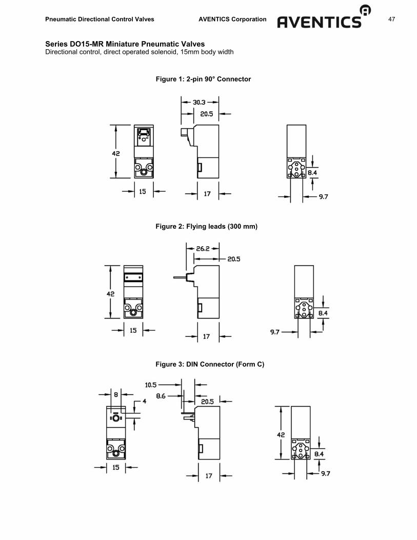
Pneumatic Directional Control Valves AVENTICS Corporation 47
Series DO15-MR Miniature Pneumatic Valves Directional control, direct operated solenoid, 15mm body width
Figure 1: 2-pin 90° Connector
Figure 2: Flying leads (300 mm)
Figure 3: DIN Connector (Form C)

48 Pneumatic Directional Control Valves AVENTICS Corporation
Series DO15-MR Miniature Pneumatic Valves Directional control, direct operated solenoid, 15mm body width
Single Subbase
Manifold Bases
Part No. No. of Stations Supply & Exhaust Ports
Working Port Y (in) Z (in)
R432033359 1 #10-32 (M5) thread #10-32 (M5) thread -- --
R432037218 2 1/8” NPT #10-32 (M5) thread 2.00 1.610
R432037219 3 1/8” NPT #10-32 (M5) thread 2.63 2.240
R432037220 4 1/8” NPT #10-32 (M5) thread 3.26 2.870
R432037221 5 1/8” NPT #10-32 (M5) thread 3.89 3.500
R432037222 6 1/8” NPT #10-32 (M5) thread 4.52 4.130
R432037223 8 1/8” NPT #10-32 (M5) thread 5.78 5.390
R432037224 10 1/8” NPT #10-32 (M5) thread 7.04 6.650
R432037225 12 1/8” NPT #10-32 (M5) thread 8.30 7.910
R432037226 14 1/8” NPT #10-32 (M5) thread 9.56 9.170
R432037227 16 1/8” NPT #10-32 (M5) thread 10.82 10.430
R432033358 Blanking plate -- -- -- --
Single subbase and manifold bases for DO15-MR valves
Note: Additional versions available, contact Technical Support at the factory.
1/8-27 NPT .440DP (4) PLS. NEAR & FAR SIDE
Ø .325 .177 DP Ø .177 THRU (2) PLS.
M5x0.8 THREAD 0.20 DP
‘Y’
.377
.820 .630
.197 ‘Z’
I . 208 (2) PLS.
.609
1.398
.869
.350
.837

Pneumatic Directional Control Valves AVENTICS Corporation 49
Series DO15-MR Miniature Pneumatic Valves Directional control, direct operated solenoid, 15mm body width
Blanking plate for DO15-MR valves, Part no. R432033358
Connector Cables (for 2-pin connectors)
Solenoid Connectors
(DIN 43650 Form C connectors shown)
Part No. Cable Length
R432033338 300mm
R432033339 600mm
R432033340 1 meter
Part No. Type Description
8941012202 DIN 43650 Form C Non-lighted, without lead
R432011982 DIN 43650 Form C LED, 24VDC, without lead
R432011962 DIN 43650 Form C LED, 24VDC, 3’ lead
R432011964 DIN 43650 Form C LED, 24VDC, 6’ lead
R432034286 AMP Faston Non-lighted, without lead
R432034287 AMP Faston LED, 24VDC, without lead
R432034288 AMP Faston LED, 110VAC, without lead
R432034289 AMP Faston LED, 220VAC, without lead
(Non-lighted) (mm)
(With LED) (inches)

50 Pneumatic Directional Control Valves AVENTICS Corporation
Voltage tolerance: ±10%
FEATURES ■ Direct acting, poppet design ■ 3-way normally closed, single solenoid ■ Manifold capabilities, 2 thru 8 stations ■ Operates with lubricated or nonlubricated air
NOTE: Valve mounting screws provided with subbases and manifolds are M3 x 18mm
Valve Dimensions
Subbase Dimensions
Series 830 3-Way Directional Poppet Valve Solenoid operated
Voltage Part No. 120 VAC-50/60 Hz R432006547
240 VAC-50/60 Hz R432006549
12 VDC R432006552
24 VDC R432006555
24 VAC-50/60 Hz R432006557
Valves with non-lighted connector
Voltage Part No. 120 VAC-50/60 Hz R432006548
240 VAC-50/60 Hz R432006550
12 VDC R432006553
24 VDC R432006556
24 VAC-50/60 Hz R432030351
Valves with lighted connector
Voltage Part No. 120 VAC-50/60 Hz R432006534
240 VAC-50/60 Hz R432030356
12 VDC R432006535
24 VDC R432006536
24 VAC/ 50/60Hz R432006537
Replacement Coils
TECHNICAL DATA: Port Sizes: 10-32 delivery ports with G 1/8 supply Working Pressure: 0-150 psi Flow: Cv = .06
(up to 3 SCFM w/ 150 psi pressure supply; up to 2.25 SCFM w/ 80 psi supply (15 psi pressure drop)
Temperature Range: +5°F to +122°F Media: Air, either lubricated or non-lubricated Materials: Rugged engineering plastic body with nylon
coil, subbase and manifolds or black anodized aluminum.
Manual Override: Locking
Standard Voltages (all coils rated for continuous duty)
Power Consumption
Inrush Holding
24, 120 VAC (50/60 Hz)
8.5 VA 6.9 VA
6, 12, 24 VDC 4.8 W
ELECTRICAL DATA: NEMA 4 (IP65) electrical protection
NOTE: All dimensions expressed in IN MM
dimensions in mm
Number of Valve Positions Part No. e1 e2 e3 e4 e5 e6 e7 L
Single station R432038820 22 – – – – – 34 44 2-station R432038821 22 23 – – – – 57 67 3-station R432038822 22 23 46 – – – 80 90 4-station R432038823 22 23 46 69 – – 103 113 5-station R432038824 22 23 46 69 92 – 126 136 6-station R432038825 22 23 46 69 92 115 149 159

Pneumatic Directional Control Valves AVENTICS Corporation 51
4 Way / 2 Position Solenoid & Air Pilot Poppet Valves TECHNICAL DATA: Port Sizes: Integrated Fittings: 1/4” O.D. x .040” wall poly tubing (gray tube nuts) Flow: Cv = .20 Working Pressure: 20 psi minimum (External pilots not available) 150 psi maximum (Below 105°F) - solenoid & air pilot valves 115 psi maximum (105°F - 122°F) - solenoid valves 115 psi maximum (105°F - 140°F) - air pilot valves No vacuum service Temperature Ranges: +5° to +122°F (20-115 psi) - solenoid valves +5° to +140°F (20-150 psi) - air pilot valves +5° to 105°F (20-150 psi) - solenoid & air pilot valves Media: Air (either lubricated or non-lubricated) Materials: Polyacetal Engineering Plastic with polyurethane seals and diaphragm Weight: 2.6 oz. (single solenoid) Manual Override: Locking
FEATURES ■ 4 way/4 ported directional control valve ■ Compact and lightweight (only 2.6 oz. and
requires less than 3 cubic inches of space). ■ Designed to operate on non-lubricated air. ■ Integral fitting (for 1/4” plastic tubing) for fast,
leak free connections. ■ Modular wireway system ■ NEMA 4 Electrical Protection (valve only) ■ UL Recognized ■ “Clip type” valve to manifold mounting means
valve installation and removal takes only seconds (similar to Type 740TM concept).
■ Polyacetal Engineering Plastic construction provides excellent corrosion resistance.
■ Poppet type valve design provides millions of trouble free cycles.
■ Manual override standard. ■ Twist lock coil design (no tools required) permits
convenient interchangeability between AC and DC coils
■ 3 snap together modular manifold sections facilitate most manifold requirements (accommodates 3/8” O.D. tubing for both supply and exhaust).
■ Cycle life - 20-100 million cycles ■ Response time: Supply pressure 90 psi Energized-(0-81psi): 16ms De-energized-(90-9 psi): 18ms Response time based on 24 VDC Single
Solenoid
Series 840 Valves, 4-Way Directional Control Solenoid and air pilot, for 1/4” tubing
Standard Voltages (all coils rated for continuous duty)
Power Consumption
Inrush Holding
24, 120 VAC (50/60 Hz)
2.9 VA 2.0 VA
12, 24 VDC 1.6 W
ELECTRICAL DATA:
Voltage Tolerance: ±10% NEMA 4 ELECTRICAL PROTECTION NOTE: Solenoid connectors must be ordered sepa-rately, one per solenoid. See complete listing on the Solenoid Connectors page. OPTIONS: Wireways - (see following pages) Solenoids with indicators lights available-contact AVENTICS
MANIFOLD MOUNTING (Simple field assembly, or factory assembled manifold are available.)
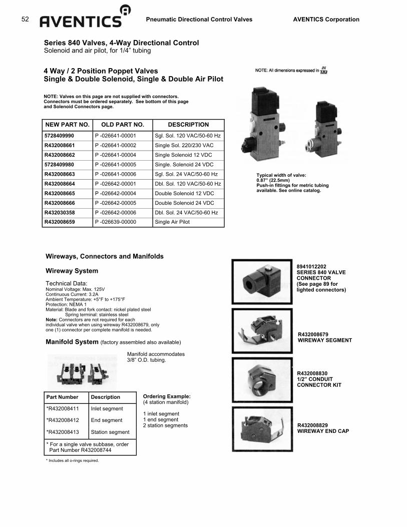
52 Pneumatic Directional Control Valves AVENTICS Corporation
Series 840 Valves, 4-Way Directional Control Solenoid and air pilot, for 1/4” tubing
NOTE: Valves on this page are not supplied with connectors. Connectors must be ordered separately. See bottom of this page and Solenoid Connectors page.
* Includes all o-rings required.
8941012202 SERIES 840 VALVE CONNECTOR (See page 89 for lighted connectors)
R432008679 WIREWAY SEGMENT
R432008830 1/2” CONDUIT CONNECTOR KIT
R432008829 WIREWAY END CAP
NEW PART NO. OLD PART NO. DESCRIPTION
5728409990 P -026641-00001 Sgl. Sol. 120 VAC/50-60 Hz
R432008661 P -026641-00002 Single Sol. 220/230 VAC
R432008662 P -026641-00004 Single Solenoid 12 VDC
5728409980 P -026641-00005 Single. Solenoid 24 VDC
R432008663 P -026641-00006 Sgl. Sol. 24 VAC/50-60 Hz
R432008664 P -026642-00001 Dbl. Sol. 120 VAC/50-60 Hz
R432008665 P -026642-00004 Double Solenoid 12 VDC
R432008666 P -026642-00005 Double Solenoid 24 VDC
R432030358 P -026642-00006 Dbl. Sol. 24 VAC/50-60 Hz
R432008659 P -026639-00000 Single Air Pilot
Typical width of valve: 0.87” (22.5mm) Push-in fittings for metric tubing available. See online catalog.
4 Way / 2 Position Poppet Valves Single & Double Solenoid, Single & Double Air Pilot
Wireways, Connectors and Manifolds Wireway System Technical Data: Nominal Voltage: Max. 125V Continuous Current: 3.2A Ambient Temperature: +5°F to +175°F Protection: NEMA 1 Material: Blade and fork contact: nickel plated steel Spring terminal: stainless steel Note: Connectors are not required for each individual valve when using wireway R432008679, only one (1) connector per complete manifold is needed. Manifold System (factory assembled also available) Manifold accommodates 3/8” O.D. tubing.
Part Number Description
*R432008411 Inlet segment
*R432008412 End segment
*R432008413 Station segment
* For a single valve subbase, order Part Number R432008744
Ordering Example: (4 station manifold) 1 inlet segment 1 end segment 2 station segments

Pneumatic Directional Control Valves AVENTICS Corporation 53
Series 840 Valves, 4-Way Directional Control Solenoid and air pilot, for 1/4 tubing
DIMENSIONS SGL AIR PILOT
1.) Mounting space for nameplate.
SGL SOLENOID DBL SOLENOID
1.) Connector rotates at 90° intervals. 2.) LED indicator. 3.) Coil rotates at 90° intervals. 4.) Mounting space for nameplate.
1.) Manual overrides. 2.) Connector rotates at 90° intervals. 3.) LED indicator. 4.) Coil rotates at 90° intervals. 5.) Mounting spaces for nameplate. 6.) Hole for M5 fitting or silencer (Ø 4.5mm).

54 Pneumatic Directional Control Valves AVENTICS Corporation
Series 840 Valves, 4-Way Directional Control System drawing and wireway electrical information
Total System Drawing
Wireway Electrical Connection
NOTE: Optional supply ports are available by drilling and tapping a #10-32 thread into the bottom or side of the manifold. “O” rings (provided with each manifold segment) should be lubricated before installation. Valve to manifold “O” ring - Part no. 8970724744 Manifold to manifold “O” ring - Part no. 8970862504 Subbases can be mounted with DIN rail (en 50 022) or with #8 screws. First, last, and every fourth station should be secured if DIN rail mounting is not used.

Pneumatic Directional Control Valves AVENTICS Corporation 55
Series 840 Valves, 4-Way Directional Control Accessories and repair parts
ACCESSORIES
PART NUMBER DESCRIPTION
8930715002 Blanking Cap (for either delivery port)
R432008328 Elbow Fitting (1/4” for valve)
R432008416 Double Elbow Fitting (1/4” for valve)
5324002000 Exhaust Silencer (for valve)
5324002020 Exhaust Silencer (for manifold)
R432015479 Elbow Fitting (1/4” for manifold)
R432015301 Elbow Fitting (3/8” for manifold)
R432008420 Manifold Blanking Plate Kit
5728400092 Dual Pressure Manifold Kit
R432008514 Tube Nut Kit (2 pcs.) for manifold 3/8”
R432015689 Tube Nut Kit (2 pcs.) for valve 1/4”
8930714804 Tube nut, black. For 6 mm x 1 mm wall Poly tubing
8993800114 Exhaust Muffler (Silencer for pilot)
R432015679 Exhaust Fitting Kit (2 pcs.)
Blanking Cap 8930715002 Single Elbow R432008328 Double Elbow R432008416 Valve Exhaust Silencer 5324002000 Manifold Exhaust Silencer 5324002020 1/4” Manifold Elbow R432015479 3/8” Manifold Elbow R432015301 Manifold Blanking Plate R432008420 Dual Pressure Manifold Kit 5728400092 Exhaust Silencer for Pilot 8993800114 Exhaust Fitting Kit R432015679
MANIFOLDS
PART NUMBER DESCRIPTION
R432008411 Inlet Segment
R432008412 End Segment
R432008413 Station Segment
R432008744 Single Subbase (used to manifold mount a single valve.)
DIN RAIL MOUNTING BARS PART NUMBER DESCRIPTION
R432008414 DIN Rail Mounting Bar (6”)
R432008415 DIN Rail Mounting Bar (12”)
Complete manifold assemblies snap or slide onto DIN rail. Consult factory for longer lengths of DIN rail.
“SNAP” COILS
(Includes coil, armature, & plunger)
PART NUMBER DESCRIPTION
5420935270 120 VAC/50-60 Hz
5420930210 12 VDC
5420930220 24 VDC
5420935220 24 VAC/50-60 Hz
5428405480 220/230 VAC
Accessories & Repair Parts 4 Way / 2 Position Poppet Valves

56 Pneumatic Directional Control Valves AVENTICS Corporation
Series 740 Valves Specifications and features
Flow: Cv=0.7 - with Integrated Fittings (Cv=1.3 - comparable flow to threaded port valve)
4 Way / 2 & 3 Position Solenoid & Air Pilot Operated Diaphragm-Poppet Valve TECHNICAL DATA: Port Sizes: Integrated Fittings for 3/8”, 5/16”, and 8mm tubing Push-in fitting styles bodies available for metric tubing only (2 position only) Working Pressure: 20 PSI minimum 150 PSI maximum External Pilots not available
ELECTRICAL DATA:
Standard Voltage (all coils are rated for
continuous duty)
Power Consumption
Inrush Holding
24 VAC-50/60 Hz, 110V-50 Hz/120V-60 Hz 220V-50 Hz/240V
6.4 VA
3.7 VA
6, 12, 24 VDC 2.7 W
Voltage Tolerance: +10% (Except for Explosion proof and Intrinsically safe solenoids.) NOTE: Electrical connectors must be ordered separately. One per solenoid required. See complete listing on Solenoid Connectors page.
Recommended Tubing: Standard 3/8” O.D> x 0.062” wall - poly tubing *5/16” O.D. x 0.040 wall - nylon tubing *8mm x 1.00mm wall poly tubing *Requires optional tube nut kit (R432015289) Valves designed for 10mm O.D. x 1mm wall poly tubing are also available. Adapters available: 1/4” O.D. x 0.040 wall - poly tubing. Tube nuts are supplied with each valve for 3/8” x 0.062 wall poly tubing Features: ■ NEMA 4 Electrical protection ■ cURus (Dual CSA/UL Recognized) coil versions available ■ Packaged as a cylinder/valve combination with TaskMaster® cylinders sizes 1 1/2” thru 4”. See catalog SC-200. ■ Integrated fittings ■ Adjustable built-in flow controls in R and S exhausts on two position valves ■ Cycle life: 20 to 150 million cycles ■ Response time for 24VDC single solenoid valve: (at supply pressure 85 psi) On (0-77 psi) 18ms or less Off (85-8 psi) 32 ms or less

Pneumatic Directional Control Valves AVENTICS Corporation 57
Series 740 Valves Single and double solenoid, 5/2
Unique Manual Override Feature: Single solenoid valves are equipped with a convertible manual override button. Valve comes standard with extended locking override. By snipping tab off of plastic button, override becomes non-locking extended. By snipping button at first scored line, it becomes a flush non-locking override. By snipping at second scored line, a flush locking override is ob-tained, requiring a screwdriver to actuate.
NEW PART NO. OLD PART NO. VOLTAGE
R432016659 PW-067715-00001 110 VAC 50Hz/120 VAC 60Hz
R432016660 PW-067715-00002 220 VAC 50Hz/240 VAC 60Hz
R432016661 PW-067715-00003 6 VDC
R432016662 PW-067715-00004 12 VDC
R432016663 PW-067715-00005 24 VDC
R432016664 PW-067715-00006 24 VAC 50/60 Hz
R432002437 without coil
NEW PART NO. OLD PART NO. VOLTAGE
5727495270 PW-067697-00001 110 VAC 50Hz/120 VAC 60Hz
R432016655 PW-067697-00002 220 VAC 50Hz/240 VAC 60Hz
R432016656 PW-067697-00003 6 VDC
R432016657 PW-067697-00004 12 VDC
5727490220 PW-067697-00005 24 VDC
R432016658 PW-067697-00006 24 VAC 50/60 Hz
R432002436 without coil
NOTE: Electrical connector must be ordered separately. One per solenoid required, see Solenoid Connectors page. All valves on this page come with 3/8” tube nuts designed to accommodate 3/8” x 0.062” wall poly tubing. Valves with tube nuts for 5/16” (8mm) tubing, 10mm tubing, and push-in fitting style bodies available.
4 Way / 2 Position Solenoid Operated Diaphragm Poppet Valve
SINGLE SOLENOID WITH AIR SPRING RETURN
DOUBLE SOLENOID OPERATED The external non-locking manual override button may be pushed from one side to the other to select which delivery port is pressurized initially.
2 POSITIONS
Typical width of valve: 1.38” (35.0mm) See next page for U.L. recognized and CSA approved coils.
THE CONNECTOR CAN BE FIXED IN POSITIONS AT 90 INTERVALS

58 Pneumatic Directional Control Valves AVENTICS Corporation
Series 740 Valves Double solenoid 5/3 and U.L. recognized/CSA approved models
4 Way / 3 Position, Double Solenoid Operated Diaphragm-Poppet Valve
NEW PART NO. OLD PART NO. DESCRIPTION SYMBOL
CLOSED CENTER VERSION R432016670 PW-067717-00001 110 VAC 50 Hz/120 VAC 60 Hz
R432016671 PW-067717-00002 220 VAC 50 Hz/240 VAC 60 Hz
R432016672 PW-067717-00003 6 VDC
R432016673 PW-067717-00004 12 VDC
R432016674 PW-067717-00005 24 VDC
R432016675 PW-067717-00006 24 VAC 50/60 Hz
R432002438 without coil EXHAUST OPEN CENTER VERSION
R432016665 PW-067716-00001 110 VAC 50 Hz/120VAC 60 Hz
R432016666 PW-067716-00002 220 VAC 50 Hz/240 VAC 60 Hz
R432016667 PW-067716-00004 12 VDC
R432016668 PW-067716-00005 24 VDC
R432016669 PW-067716-00006 24 VAC 50/60 Hz
R432002439 without coil
Warning: Do not energize both solenoids at same time or all ports may be pressurized or exhausted. __________________________________________________________________________________________________________________
PART NO. DESCRIPTION
R432038437 5/2 Single Solenoid, w/ 24VDC
R432038419 5/2 Single Solenoid, w/ 110VAC 50/60Hz
R432038438 5/2 Double Solenoid, w/ 24VDC
R432038420 5/2 Double Solenoid, w/ 110VAC 50/60Hz
R432038439 5/3 Closed Center, w/ 24VDC
R432038421 5/3 Closed Center, w/ 110VAC 50/60Hz
R432038440 5/3 Open Center, w/ 24VDC
R432038422 5/3 Open Center, w/ 110VAC 50/60Hz
These valves do not include solenoid connectors. Order one per solenoid. See com-plete listing on Solenoid Connectors page. Dimensions are the same as our standard models.
NOTE: Electrical connector must be ordered separately. One per solenoid required, see Solenoid Connectors page. All valves on this page come with 3/8” tube nuts designed to accommodate 3/8” x 0.062” wall poly tubing.
4 Way / 2 Position, Solenoid Operated Valves With cURus Approved Operators

Pneumatic Directional Control Valves AVENTICS Corporation 59
Series 740 Valves Intrinsically safe solenoid valves, 5/2
4 Way 2 Position Intrinsically Safe Solenoid Valve for Hazardous Locations Notice: Part number R432008894 has been discontinued.

60 Pneumatic Directional Control Valves AVENTICS Corporation
Series 740 Valves Solenoid valves 5/2 with larger integrated fittings
NEW PART NO. OLD PART NO. DESCRIPTION
R432016647 PW-027860-00001 110 VAC 50 Hz/120VAC 60 Hz Single Solenoid
R432016648 PW-027860-00002 220 VAC 50 Hz/240VAC 60 Hz Single Solenoid
R432016649 PW-027860-00005 24 VDC Single Solenoid
R432016650 PW-027860-00006 24 VAC 50/60 Hz Single Solenoid
NEW PART NO. OLD PART NO. DESCRIPTION
R432016651 PW-027897-00001 110 VAC 50 Hz/120VAC 60 Hz Double Solenoid
R432016652 PW-027897-00002 220 VAC 50 Hz/240VAC 60 Hz Double Solenoid
R432030385 PW-027897-00004 12 VDC Double Solenoid
R432016653 PW-027897-00005 24 VDC Double Solenoid
R432016654 PW-028797-00006 24 VAC 505/60 Hz Double Solenoid
NEW PART NO. OLD PART NO. DESCRIPTION
5727475280 572-747-528-0 220 VAC 50 Hz/240vac 60 Hz Single Solenoid
5727470220 572-747-022-0 24 VDC Single Solenoid
5727475302 572-747-530-2 Base Valve - No Solenoid*
NEW PART NO. OLD PART NO. DESCRIPTION
5727485280 572-748-528-0 220 VAC 50 Hz/240vac 60 Hz Double Solenoid
5727480220 572-748-022-0 24 VDC Double Solenoid
5727485302 572-748-530-2 Base Valve - No Solenoid*
NEW PART NO. OLD PART NO. DESCRIPTION
R432015405 P -068700-K0000 Single Solenoid
R432015410 P -068704-K0000 Double Solenoid
4 Way / 2 Position Solenoid Operated Standard Series 740 valve with tube nuts for 5/16” (0.040 wall) nylon tubing or 8mm (1mm wall) poly tubing. Push-in fittings are for 10mm (1mm wall) poly tubing. NOTE: Electrical connectors must be ordered separately. One per solenoid required, see Solenoid Connectors page.
2 Position, Standard fittings
Single Solenoid
Double Solenoid
2 Position, Push-in fittings (10mm O.D. tubing)
Single Solenoid
Double Solenoid
* Base valves are supplied without coil(s) or connector(s) which must be ordered separately (see later page)
Series 740 Valve with 10mm Supply and Delivery Ports for higher flow applications - 2 Position
Note: Use with 10mm O.D. x 1mm wall poly tubing
10mm Valves are supplied without coil(s) or connector(s) which must be ordered separately (see later pages).

Pneumatic Directional Control Valves AVENTICS Corporation 61
Series 740 Valves Corrosion Resistant version
CORROSION RESISTANT MODELS
2-POSITION VALVES Without Indicator Lights
New Part Old Part Description Number Number
R432015590 P -069294-00001 110VAC-50Hz/120VAC-60Hz Single Sol. R432015591 P -069294-00002 220VAC-50Hz/240VAC-60Hz Single Sol. R432015592 P -069294-00004 12 VDC Single Solenoid R432015593 P -069294-00005 24 VDC Single Solenoid R432015594 P -069294-00006 24 VAC-50/60Hz Single Solenoid R432015597 P -069297-00001 110VAC-50Hz/120VAC-60Hz Double Sol. R432015598 P -069297-00002 220VAC-50Hz/240VAC-60Hz Double Sol. R432015599 P -069297-00005 24 VDC Double Solenoid
2-POSITION VALVES With Indicator Lights
New Part Old Part Description Number Number
R432015613 P -069344-00001 110VAC-50Hz/120VAC-60Hz Single Sol. R432015614 P -069344-00004 12 VDC Single Solenoid R432015615 P -069344-00005 24 VDC Single Solenoid R432015616 P -069344-00006 24 VAC-50/60Hz Single Solenoid R432015617 P -069345-00001 110VAC-50Hz/120VAC-60Hz Double Sol. R432015618 P -069345-00002 220V-50Hz/240V-60Hz Double Solenoid R432015619 P -069345-00005 24 VDC Double Solenoid
R432008862 P -027873-00001 110VAC-50Hz/120VAC-60Hz Open Center R432008863 P -027873-00005 24 VDC Exhaust Open Center
3-POSITION VALVES Without Indicator Lights
New Part Old Part Description Number Number
R432008644 P -026564-00001 110VAC-50Hz/120VAC-60Hz Closed Ctr. R432008645 P -026564-00005 24 VDC Closed Center
All fasteners and exposed metallic parts for the 2-position valves are 300 series stainless steel. The adjustable built-in flow control adjustment screws for the 3-position valves are zinc plated carbon steel, with all other fasteners and exposed metallic parts 300 series stainless steel. These valves are recommended for most daily wash-down applications such as food processing, breweries and dairy plants, or anywhere else that corrosion can be a problem. Dimensions are the same as standard valves.
4 Way / 2 and 3 Position Solenoid Operated Corrosion Resistant Series 740 Valves

62 Pneumatic Directional Control Valves AVENTICS Corporation
Series 740 Valves Air pilot, single and double
4 Way / 2 Position Air Pilot Operated SINGLE AIR PILOT VALVES Part No. R432013808 (old P - 067698-00000)
DOUBLE AIR PILOT VALVES
Part No. R432013810 (old P - 067700-00000)
FOR DOUBLE AIR PILOT Manual override standard. This unique, external non-locking manual override button for the double air pilot may be pushed from one side to the other to select which delivery port is pressurized. Double Air Bleeder Valve: Part No. R432008442 (old P - 026125-00000 OPERATION Exhausting either air pilot port while the opposite port is still pressurized will shift the valve. Valve features stainless steel fasteners for corrosion resistance.
Typical width of valve: 1.38” (35.0mm)
NOTE: All dimensions expressed in IN MM

Pneumatic Directional Control Valves AVENTICS Corporation 63
ORDERING EXAMPLE (4 Station Manifold): 1 - Inlet segment 1 - End segment 2 - Station segment
Series 740 Valves Manifolds and gang stacking
NEW PART NO. OLD PART NO. DESCRIPTION
R432013811 *P -067701-00000 Inlet Segment R432013812 *P -067702-00000 End Segment R432013813 *P -067703-00000 Station Segment R432015880 *P -069881-00000 Single Subbase (Identical to inlet
segment except rear cavities are blocked. Used to manifold mount one valve only.
4 Way / 2 and 3 Position Manifold Mounts & Gang Stacking Manifold Mounting, Snap-Together Assembly (Factory assembled manifolds also available)
Gang Stacking Arrangement
SHEAR PLUG KNOCKOUT Ganged assembly-common supply pressure obtainable by knockout shear plugs Mounting Accessories Kit Part Number R432013852 Includes O-ring (for sealing between the valve bodies) and an inlet port blanking cap. (Bolts and Nuts are not included). Stack can be held together and mounted with readily available 1/8” ‘all thread” material. MANIFOLD INSTALLATION NOTE: The first and last segment should always be securely mounted to a plate. If more than five valves are used, every third valve segment should also be securely mounted.
NOTE: Yellow lock tab on manifold segments are scored. This allows the end to be broken off (if desired), making it tamper resistant, thus requiring a screwdriver to remove valve.
No of Stations A B
2.89 3.01 (73.5) (76.5)
3 4.39 4.51 (111.5) (114.5)
4 5.89 6.00 (149.5) (152.5)
5 7.38 7.50 (187.5) (190.5)
6 8.88 9.00 (225.5) (228.5)
7 10.37 10.49 (263.5) (266.5)
8 11.87 11.99 (301.5) (304.5)
9 13.37 13.48 (339.5) (342.5)
10 14.86 14.98 (377.5) (380.5)
2
* Required O-rings included
MANIFOLDS - OUTLINE DIMENSIONS
Part No. R432013853 O-Ring Kit (included with manifold segments)
NOTE: All dimensions expressed in IN MM
O-Ring Pc. No 8970701004 Included with Segments Lubricate “O” Rings with Dow Corning 55 before assembly

64 Pneumatic Directional Control Valves AVENTICS Corporation
Series 740 Valves Accessories
ACCESSORIES
R432015301 Elbow Fitting with nuts for
3/8” & 5/16” O.D. tubing
R432015479 Reducer Elbow Fitting with nut for 1/4” O.D. (.040” wall) tubing
R432015475 Reducer Fitting with nut
For 1/4” O.D. tubing
R432013850 Exhaust Tube Nut & Silencer
(2 kits shown)
8919905502 (3/8”, 5/16” or 8 mm) 8919905512 (10 mm)
Blanking Cap (converts 4-way to 3-way)
R432013852 Sheer Plug Knockout for
Stacking
R432015513 Exhaust Fitting Adapter Kit
(converts the standard exhaust fitting to a tube fitting for external piping)
R432015289 Tube Nuts (3 ea.) for 5/16”
(.040” wall) O.D. nylon tubing or 8mm (1mm wall) O.D. poly
tubing
R432015287 Tube Nuts (3 ea.) for 3/8”
O.D. (.062” wall) poly tubing
R432015511 Manifold Blanking Plate
(use to block one segment)
R432015330 Manifold Bushing Kit
for two supply pressures
R432015512 Individual Manifold Supply Pres-
sure Kit-mounts underneath mani-fold segment (not included)
R432015527 Double Elbow Fitting for 1/4”
O.D. tubing
R432015526 Double Elbow Fitting for 3/8” &
5/16” O.D. tubing
R432015525 Barb Fitting for 1/4” I.D.
Reinforced Hose

Pneumatic Directional Control Valves AVENTICS Corporation 65
Series 740 Valves Repair Kits
Part No. Old Part No. Description R432013884 P -067916-00000 Single Solenoid Body Repair Kit R432013885 P -067917-00000 Double Solenoid Body Repair Kit
(includes 3 position valves also) R432013854 P -067817-00000 Air Pilot Operator Kit R432013816 P -067705-K0000 Single Solenoid Body Assembly R432013814 P -067704-K0000 Double Solenoid Body Assembly R432015687 P -069541-00000 Solenoid Repair Kit, includes
armature, plunger/spring & seal 8994702802 H -899470-02802 Solenoid Retainer Kit R432013839 P -067782-00000 Valve Latch & Spring R432013853 P -067816-00000 Valve Manifold Station "O" Ring Kit,
(to attach valve to manifold)
Repair Kits and Parts
Solenoid Kits (Includes Armature, Coil, & Mtg. Hardware)
Part No. Old Part No. Description R432015349 P -068648-00000 24 VAC-50/60Hz R432013840 P -067783-00000 110VAC-50Hz/120VAC-60Hz R432013841 P -067784-00000 220VAC-50Hz/240VAC-60Hz R432029180 P -067785-00000 6 VDC R432013842 P -067786-00000 12 VDC R432013843 P -067787-00000 24 VDC
U.L. Recognized & C.S.A. Approved Coils Part No. Description
R432034080 12 VDC R432009779 24 VDC R432009778 110 VAC-50/60Hz
Part No. Model Number Description R432011985 P -048835-00001 110VAC-50Hz/120VAC-60Hz R432011986 P -048835-00002 220VAC-50Hz/240VAC-60Hz R432011988 P -048835-00004 12 VDC R432011989 P -048835-00005 24 VDC R432011990 P -048835-00006 24 VAC-50/60Hz
Standard Coils
Part No. Model Number Description 5428457072 H -542845-07072 110VAC-50Hz/120VAC-60Hz 5428457082 H -542845-07082 220VAC-50Hz/240VAC-60Hz 5420507012 H -542050-07012 12 VDC 5420507022 H -542050-07022 24 VDC 5428457022 H -542845-07022 24 VAC-50/60Hz
Coils for Corrosion Resistant Valves
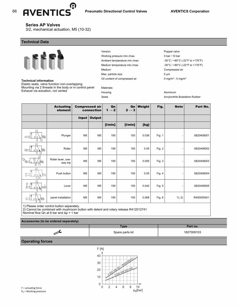
66 Pneumatic Directional Control Valves AVENTICS Corporation
Series AP Valves 3/2, mechanical actuation, M5 (10-32)
Technical Data
Technical information Elastic seals, valve function non-overlapping Mounting via 2 threads in the body or in control panel Exhaust via actuation, not vented
Operating forces
Accessories (to be ordered separately) Type Part no.
Spare parts kit 1827009103
Version Poppet valve Working pressure min./max. 0 bar / 10 bar Ambient temperature min./max. -30°C / +80°C (-22°F to +176°F) Medium temperature min./max. -30°C / +80°C (-22°F to +176°F) Medium Compressed air Max. particle size 5 µm Oil content of compressed air 0 mg/m³ - 5 mg/m³
Materials:
Housing Aluminum Seals Acrylonitrile Butadiene Rubber
F = actua ng force PB = Working pressure
Actuating element
Compressed air connection
Qn 1 → 2
Qn 2 → 3
Weight Fig. Note Part No.
Input Output
[l/min] [l/min] [kg]
Plunger M5 M5 190 150 0.036 Fig. 1 - 0820408001
Roller M5 M5 190 150 0.05 Fig. 2 - 0820408002
Roller lever, one-way trip M5 M5 190 150 0.055 Fig. 3 - 0820408003
Push button M5 M5 190 150 0.05 Fig. 4 - 0820408004
Lever M5 M5 190 150 0.042 Fig. 5 - 0820408005
panel installation M5 M5 190 150 0.068 Fig. 6 1); 2) R450055451
1) Please order control button separately. 2) Cannot be combined with mushroom button with detent and rotary release R412012741 Nominal flow Qn at 6 bar and Δp = 1 bar
00
10
20
30
40
F [N]
2 4 6 8 10pB[bar]
0 820 408 002-004
0 820 408 001 / R450055451
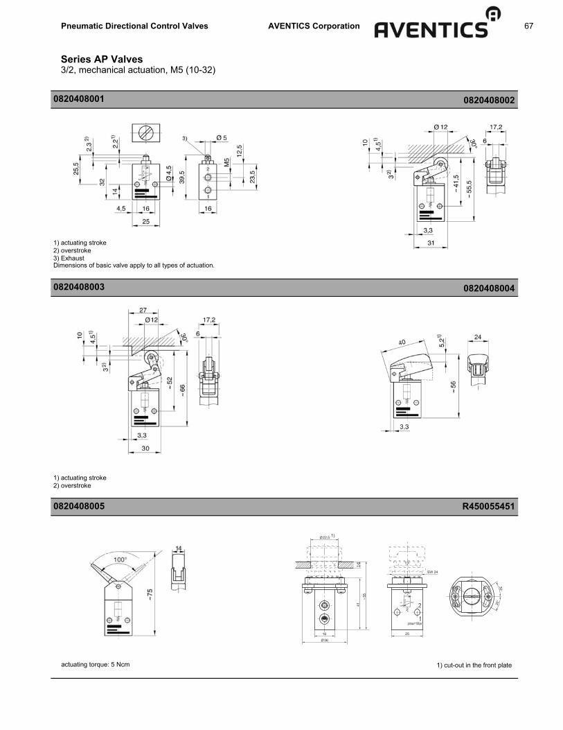
Pneumatic Directional Control Valves AVENTICS Corporation 67
Series AP Valves 3/2, mechanical actuation, M5 (10-32)
0820408001 0820408002
0820408003 0820408004
0820408005
1) actuating stroke 2) overstroke
actuating torque: 5 Ncm 1) cut-out in the front plate
1) actuating stroke 2) overstroke 3) Exhaust Dimensions of basic valve apply to all types of actuation.
36
22,5
16
411-
6
55
25
SW 24
213
pmax=10bar
1)
R450055451

68 Pneumatic Directional Control Valves AVENTICS Corporation
Series AP Valves 3/2, mechanical actuation, 1/8” NPT or G1/8
Technical Data Valve type Poppet valve Working pressure 0 - 10 bar (0-10psi) Nominal flow rate 1 → 2: 250 l/min (0.25 Cv); 2 → 3: 150 l/min (0.15 Cv) Operating force see diagram Temperature range -30°C to +80°C (-22°F to +176°F) Medium Compressed air, lubricated (class 5-4-5 acc. to ISO 8573-1:2001) or non-lubricated (class 3-4-3 acc. to ISO 8573-1:2001) Weight see table Material Valve body Aluminum Seals Acrylonitrile Butadiene Rubber Technical information Elastic sealing, valve function non-overlapping Vented exhaust at all exhaust ports Mounting via 2 threads in the body or in control panel Can also be used as 2/2 by closing off one port
Part no.
Symbol Control device Weight [kg] (lbs) Part no. G1/8 Part no. 1/8” NPT
Plunger 0,070 (0.154) 0820402101 —
Roller 0,080 (0.176) 0820402102 0820402108
Roller lever, one-way trip 0,085 (0.187) 0820402103 0820402109
Push button 0,085 (0.187) 0820402104 —
Lever 0,075 (0.165) 0820402105 —
Control panel installation* 0,090 (0.198) R450055452 —
Accessories (to be ordered separately) Type Part no.
Spare parts kit 1827009379 *Control device for panel installation
Name plates for control devices Additional accessories
Operating forces
F = actuating force PB = Working pressure
00
20
10
30
40
50
2 4 6 8 10
F [N]
pB[bar]
0 820 402 102-104
0 820 402 101 / R450055452 / 4
53

Pneumatic Directional Control Valves AVENTICS Corporation 69
Cut-out in the front plate
0820408001 or 0820402111 R450055452
0820408001 or 0820402109 0820402104 or 0820402110
0820408001 0820402102 or 0820402108
Series AP Valves 3/2, mechanical actuation, 1/8” NPT or G1/8
1) actuating stroke 2) overstroke Dimensions of basic valve apply to all types of actuation.
1) actuating stroke 2) overstroke
213
pmax=10bar
22,5
32 16
36
601-
6
74
SW 24
1)

70 Pneumatic Directional Control Valves AVENTICS Corporation
Part no.
Symbol Control device Weight [kg] (lbs) Part no. G1/4 Part no. 1/4” NPT
Plunger 0,165 (0.364) 0820400001 0820400010
Roller 0,265 (0.584) 0820400002 —
Roller lever, one-way trip 0,280 (0.617) 0820400003 0820400012
Lever, horizontal 0,290 (0.639) 0820400004 —
Lever, vertical 0,270 (0.595) 0820400005 0820400014
Pedal 1,200 (2.646) 0820400006 0820400015
Pedal with detent 1,220 (2.690) 0820400008 —
Series AP Valves 3/2, mechanical actuation, 1/4” NPT or G1/4
Technical Data Valve type Poppet valve Working pressure 0 - 10 bar (0 - 145psi) Nominal flow rate 550 l/min (0.55 Cv) Operating force See diagram Temperature range -30°C to +80°C (-22°F to +176°F) Medium Compressed air, lubricated (class 5-4-5 acc. to ISO 8573-1:2001) or Non-lubricated (class 3-4-3 acc. to ISO 8573-1:2001) Weight see table Material Valve body Aluminum Seals Acrylonitrile Butadiene Rubber
Technical information Elastic sealing, valve function non-overlapping Vented exhaust at all exhaust ports Reverse flow also possible Optionally with protective cover or pedal actuation Pressure gauge connection on front Accident prevention regulations: The actuating mechanism of machines must exclude an unintentional actuation If necessary, the switch must be secured. If protected installation not possible, than installation of the pedal-operated valve under protection cover.
Accessories (to be ordered separately) Type Part no.
Spare parts kit 1827009097
Protective covers for pedal valves See end of section

Pneumatic Directional Control Valves AVENTICS Corporation 71
Series AP Valves 3/2, mechanical actuation, 1/4” NPT or G1/4
Operating forces
0820400001 or 0820400010
0820400002 0820400003 or 0820400012
F = actuating force PB = Working pressure
1) actuating stroke 2) overstroke Dimensions of basic valve apply to all types of actuation.
1) actuating stroke 2) overstroke

72 Pneumatic Directional Control Valves AVENTICS Corporation
Series AP Valves 3/2, mechanical actuation, 1/4” NPT or G1/4
0820400004 or 0820400013 0820400005 or 0820400014
0820400006 or 0820400015 0820400008 or 0820400016
1) actua ng stroke actua ng torque: 40 Ncm 1) Ball
8,3
160
138
135
1)
22
46
90
102
120
45
G1/4
200
205
119
9
160
215
1)
5 85
163
96 112
40
3727
1) optional protective cover, part number 1828104001 1) optional protective cover, part number 1828104002

Pneumatic Directional Control Valves AVENTICS Corporation 73
Series AP Valves 4/2, mechanical actuation, 1/4” NPT or G1/4
Technical Data Valve type Poppet valve Working pressure 0 - 10 bar (0 - 145psi) Nominal flow rate 550 l/min (0.55 Cv) Operating force See diagram Temperature range -30°C to +80°C (-22°F to +176°F) Medium Compressed air, lubricated (class 5-4-5 acc. to ISO 8573-1:2001) or Non-lubricated (class 3-4-3 acc. to ISO 8573-1:2001) Weight see table Material Valve body Aluminum Seals Acrylonitrile Butadiene Rubber Technical information Elastic sealing, valve function non-overlapping Vented exhaust at all exhaust ports Reverse flow also possible Optionally with protective cover or pedal actuation Pressure gauge connection on front Accident prevention regulations: The actuating mechanism of machines must exclude an unintentional actuation If necessary, the switch must be secured. If protected installation not possible, than installation of the pedal-operated valve under protection cover.
Part no.
Symbol Control device Weight [kg] (lbs) Part no. G1/4 Part no. 1/4” NPT
Plunger 0,330 (0.728) 0820401001 0820401012
Roller 0,500 (1.102) 0820401002 0820401013
Lever, horizontal 0,520 (1.146) 0820401004 —
Lever, vertical 0,530 (1.168) 0820401005 0820401016
Pedal 1,300 (2.866) 0820401006 0820401017
Pedal with detent 1,420 (3.131) 0820401008 —
Accessories (to be ordered separately) Type Part no.
Spare parts kit 1827009097
Protective covers for pedal valves See end of section

74 Pneumatic Directional Control Valves AVENTICS Corporation
Series AP Valves 4/2, mechanical actuation, 1/4” NPT or G1/4
Operating forces
0820401001 or 0820401013
F = actuating force PB = Working pressure
1) actuating stroke 2) overstroke Dimensions of basic valve apply to all types of actuation.

Pneumatic Directional Control Valves AVENTICS Corporation 75
Series AP Valves 4/2, mechanical actuation, 1/4” NPT or G1/4
0820401006 or 0820401017 / 0820401008
0820401002 or 0820401013 0820401003
0820401004 0820401005 or 0820400016
1) actuating stroke 2) overstroke
1) actuating stroke actuating torque: 40 Ncm 1) Ball
8,3
160
138
135
1)
22
46
90
102
120
45
G1/4
200
205
119
9
160
215
1)
5 85
163
96 112
40
3727
1) optional protective cover, part number 1828104001 1) optional protective cover, part number 1828104002

76 Pneumatic Directional Control Valves AVENTICS Corporation
Series AP Valves Control devices for panel installation, labels and spare parts
Control devices for panel installation
Ambient temperature min./max.
-30°C / +70°C (-22°F / 158°F)
Version Color Material Weight Delivery quantity
Fig. Note Part No.
[kg] [Piece]
Push button
Red
Polyamide 0.011 1 Fig. 1 -
R412012734
Black R412012735
Yellow R412012736
Green R412012737
Mushroom button
Red
Polyamide 0.024 1 Fig. 2 -
R412012738
Green R412012739
Yellow R412012740
Mushroom button with detent and rotary
release Red Polyamide 0.047 1 Fig. 3 1) R412012741
Lever switch Red
Polyamide 0.014 1 Fig. 4 - R412012742
White R412012743
Rotary switch with two notched positions
Red Polyamide 0.02 1 Fig. 5 -
R412012744
Grey R412012745
Push button with detent and rotary release Black Polyamide 0.032 1 Fig. 6 - R412012748
Rotary lock with two keys Grey Polyamide 0.05 1 Fig. 7 2)
3) R412012746 R412015479
1) Only for ST series spring-return valves (R422002211, R422002213) 2) The key can be removed only if the button is in the actuated state. 3) The key can be removed in the actuated or non-actuated state. Note: For dimensions, see online catalog
Technical Remarks
■ Combining an ST control panel valve with an actuating control may create an emergency OFF control device, which must comply with the applicable regulations in the EC Machinery Directive 2006/42/EC and the EN ISO 13850 and EN ISO 13849 standards. In terms of EN ISO 13849, an ST control panel valve is a single-channel component. A sturdier architecture must be selected to attain a higher performance level (c, d, e).

Pneumatic Directional Control Valves AVENTICS Corporation 77
Series AP Valves Control devices for panel installation, labels and spare parts
Installation opening and spacings for control devices
For version with label base 55 mm
Version Color Material Weight Fig. Note Part No.
[kg]
Label base Anthracite Polyamide 0.003 Fig. 1 - R412012749
Name plates, angular silver Polyvinyl chloride 0.001 Fig. 2 - R412012750
Emergency OFF sign, round Yellow Polyvinyl chloride 0.001 Fig. 3 1) R412012751
Blanking plug Anthracite Polyamide 0.026 Fig. 4 - R412012752
Mounting nut M22x1 Black Polyamide 0.007 Fig. 5 - R412012753
Spare key - - 0.001 Fig. 6 - R412012989
Reduction , Ø30.5 to Ø22.5 - Polyamide 0.001 Fig. 7 - R412015512
1) Only for ST series spring-return valves (R422002211, R422002213) Note: for dimensions, see online catalog.
Ambient temperature min./max.
-30°C / +70°C (-22°F / 158°F)
24,1
+0,
4 0
22,3
2,2 +0,2
+0,4
0
0

78 Pneumatic Directional Control Valves AVENTICS Corporation
Series AP Valves Protective covers for 3/2 and 4/2 pedal-operated valves
Protective covers for 3/2 and 4/2 pedal-operated valves
Suitable for pedal-operated valves 0820400006, 0820400015, 0820401006, 0820401017 Protection against unintended activation Support surface with ribbed rubber (secured against slipping) Sheet metal housing, varnished Optional mounting of the protective cover on the pedal-operated valve or protective cover and pedal-operated valve on the machine
Type Weight [kg] (lbs) Part no.
Protective cover 1,000 (2.205) 1828104001
Part no.
Assembly option: 1. Pedal-operated valve with protective cover for loose mounting 2. Pedal-operated valve with protective cover for fixed mounting on a base
200
160
135
1) 2)
119
138 10
2
35
1) Ribbed rubber 2) Flat-head screw with hexagon socket M6 x 20

Pneumatic Directional Control Valves AVENTICS Corporation 79
Series AP Valves Protective covers for 3/2 and 4/2 pedal-operated valves with detent
Protection covers for 3/2 and 4/2 pedal-operated valves with detent Suitable for pedal-operated valve with detent 0820400008, 0820400016, 0820401008, 0820401018 Protection against unintended activation Varnished aluminum housing
Type Weight [kg] (lbs) Part no.
Protective cover 0,350 (0.772) 1828104002
Part no.
2 mounting screws (DIN 8458, galvanized) are included in the scope of delivery.
160
163

80 Pneumatic Directional Control Valves AVENTICS Corporation
4 Way / 2 Position Detented 4 Way / 3 Position Detented (exhaust open center) 4 Way /3 Position Detented (closed center)
TECHNICAL DATA: Port Sizes: 1/8”, 1/4” and 3/8” NPTF Working Pressure: 0 to 150 psi Flow: Cv 1/8” = 1.0, 1/4” = 1.1, 3/8” = 1.2 Temperature Range: -10°F to +175°F Media: Air, either lubricated or non-lubricated Materials: Body: Zinc die casting Seals: Buna N
1/8”, 1/4” and 3/8” NPTF 4-WAY 5-PORTED
ORDERING REFERENCE Port Size
Flow Cv
Weight lb.
New Part No. Old Part No. Description
R432013830 P -067772-00001 5 ports, 2-pos. detented
1/8” NPTF
1.0 R432013833 P -067773-00001 5 ports, 3-pos. detented (exhaust open center)
R432013836 P -067774-00001 5 ports, 3 pos. detented (closed center)
1.6
1/8” VALVES
ORDERING REFERENCE Port Size
Flow Cv
Weight lb.
New Part No. Old Part No. Description
R432013831 P -067772-00002 5 ports, 2-pos. detented
1/4” NPTF
1.1 R432013834 P -067773-00002 5 ports, 3-pos. detented (exhaust open center)
R432013837 P -067774-00002 5 ports, 3 pos. detented (closed center)
1.6
1/4” VALVES
ORDERING REFERENCE Port Size
Flow Cv
Weight lb.
New Part No. Old Part No. Description
R432013832 P -067772-00003 5 ports, 2-pos. detented
3/8” NPTF
1.2 R432013835 P -067773-00003 5 ports, 3-pos. detented (exhaust open center)
R432013838 P -067774-00003 5 ports, 3-pos. detented (closed center)
1.6
3/8” VALVES
Rotair® Block Valves 5/2 and 5/3, lever operated

Pneumatic Directional Control Valves AVENTICS Corporation 81
New Part Number Old Part Number Description
R432013883
1/8” Kit, for part numbers R432013830, R432013833, and R432013836 (old part numbers P -067772-00001, P -067773-00001, and P -067774-00001) (Includes seals, valve inserts, springs, etc.)
1/4” & 3/8” Kit, 2 and 3 Position (Includes seals, valve inserts, springs, etc.). For old and new style valves.
P -067911-00000
Rotair® Block Valves Dimensions and repair kits
Dimensions for 1/8”, 1/4” and 3/8” (all same except port sizes)
Repair Kits:
Note: Repair kits for old design part numbers P-067769-00000, P-067770-00000, and P-067771-00000 are no longer available.
Port Marking P=
A & B= R & S=
Supply Pressure Delivery (Cylinder) Ports Exhaust Ports

82 Pneumatic Directional Control Valves AVENTICS Corporation
Series CD04 Valves 3/2-way valve, 0.9 Cv, 1/8” PTF* or G 1/8 ports Manual override, with detent
Version Pilot Sealing principle Working pressure min./max. Control pressure min./max. Ambient temperature min./max. Medium temperature min./max. Medium Max. particle size Oil content of compressed air Compressed air connection Connector standard Protection call according to EN 60529:2000 with electrical connector/plug Compatibility index Duty cycle Materials: Housing Seals
Spool valve, zero overlap internal soft sealing 3 bar / 10 bar (44 psi / 145 psi) 3 bar / 10 bar (44 psi / 145 psi) -15°C / +50°C (+5°F / +122°F) -15°C / +50°C (+5°F / +122°F) Compressed air 50 µm 0 mg/m3 - 1 mg/m3 According to ANSI B1.20.3 EN 175301-803:2006 IP 65 (NEMA 4) 14 100% Die cast zinc; Polyamide, fiber-glass reinforced Acrylonitrile Butadience Rubber
Technical Remarks ■ The pressure dew point must be at least 15°C (59°F) under ambient and medium temperature and may not exceed 3°C (37°F). ■ The oil content of air pressure must remain constant during the life cycle. ■ Use only the approved oil form AVENTICS, see online chapter “Technical information”. ■ Option valve: The input and output compressed air connections can be exchanged.
The valve can thereby be used in the NC or NO operating mode.
Operating voltage Voltage tolerance Power consumption Switch-on power
DC AC 50 Hz AC 60 Hz DC AC 50 Hz AC 60 Hz DC AC 50 Hz AC 60 Hz AC 50 Hz AC 60 Hz
W VA VA VA VA 12 V - - -10% / +10% - - 4.6 - - - - 24 V - - -10% / +10% - - 4.8 - - - -
- 110 V 110 V - -20% / +10% -10% / +20% - 10.8 9.5 8.3 7.2
Holding power
Inch (PTF) Ported Versions: MO Compressed air connection Operating voltage Flow rate
value Part No.
Input Output Exhaust Pilot
control exhaust
DC AC 50 Hz
AC 60 Hz Qn Qn
1 2
NC, NO PTF
1/8-27 PTF
1/8-27 PTF
1/8-27 M5 12 V 24 V
-
- -
110 V
- -
110 V 900 900
R412012695 R412012696 R412012698
NC, NO PTF
1/8-27 PTF
1/8-27 PTF
1/8-27 M5 - - - 900 900 R412012700
[l/min]
*PTF-SAE short (NPT short) threads

Pneumatic Directional Control Valves AVENTICS Corporation 83
Series CD04 Valves 3/2-way valve, 0.9 Cv, 1/8” PTF* or G 1/8 ports Manual override, with detent
Inch (PTF) Ported Versions (cont.): Part No. Flow rate value Switch-on time Switch-off time Weight Note
Qn 2 3
[l/min] [ms] [ms] [kg]
R412012695 R412012696 R412012698
900 13 27 0.32 -
R412012700 900 - - 0.26 1)
MO = Manual override 1.) Basic valve without coil Nominal flow Qn at 6 bar (87 psi) and ∆p = 1 bar (14.5 psi)
Metric (ISO G 1/8) Ported Versions: MO Compressed air connection
Flow rate
value Part no.
Input Output Exhaust Pilot
connec-tion
Pilot control exhaust
DC AC 50 Hz
AC 60 Hz Qn
[l/min]
NC, NO G 1/8 G 1/8 G 1/8 - M5
24 V - - -
- 110 V 230 V 24 V
- 110 V 230 V 24 V
900 5772550220 5772555270 5772555280 5772555220
NC, NO G 1/8 G 1/8 G 1/8 - M5 - - - 900 5772555302
NC, NO G 1/8 G 1/8 G 1/8 G 1/8 M5
24 V - -
- 110 V 230 V
- 110 V 230 V
900 5772560220 5772565270 5772565280
NC, NO G 1/8 G 1/8 G 1/8 G 1/8 M5 - - - 900 5772565302
NC, NO - G 1/8 G 1/8 G 1/8 - M5 24 V - - 900 5772590220
Operating voltage
MO = Manual override 1) Pilot: internal 2) Pilot: external 3) Basic valve without coil 4) Higher power consumption Nominal flow Qn at 6 bar and ∆p = 1 bar
Part No. Flow rate value
Flow rate value
Working pressure min./max.
Control pressure min./max.
Ambient tempera-ture min./
max.
Medium tempera-ture min./
max.
Switch-on time
Switch-off time Weight Note
Qn 1 2
Qn 2 3
[l/min] [l/min] [bar] [bar] [°C] [°C] [ms] [ms] [kg] 5772550220 5772555270 5772555280 5772555220
900 900 3 / 10 3 / 10 -15°C / +50°C
-15°C / +50°C 13 27 0.3 1)
5772555302 900 900 3 / 10 3 / 10 -15°C / +50°C
-15°C / +50°C - - 0.25 1); 3)
5772560220 5772565270 5772565280
900 900 -0.95 / 10 3 / 10 -15°C / +50°C
-15°C / +50°C 13 27 0.3 2)
5772565302 900 900 -0.95 / 10 3 / 10 -15°C / +50°C
-15°C / +50°C - - 0.25 2); 3)
5772590220 900 900 2.6 / 10 2.6 / 10 -20°C / +80°C
-20°C / +80°C 13 27 0.3 1); 4)

84 Pneumatic Directional Control Valves AVENTICS Corporation
Series CD04 Valves 3/2-way valve, 0.9 Cv, 1/8” PTF* or G 1/8 ports Manual override, with detent
Dimensions mm (Ports 1/8” PTF or ISO G1/8)
1) Metric version only with external pilot control G1/8 2) Coil can be rotated at 90° internals 3) After removal of cap M5 internal thread M5 4) Electrical connector can be plugged at 180° intervals 5) Manual override
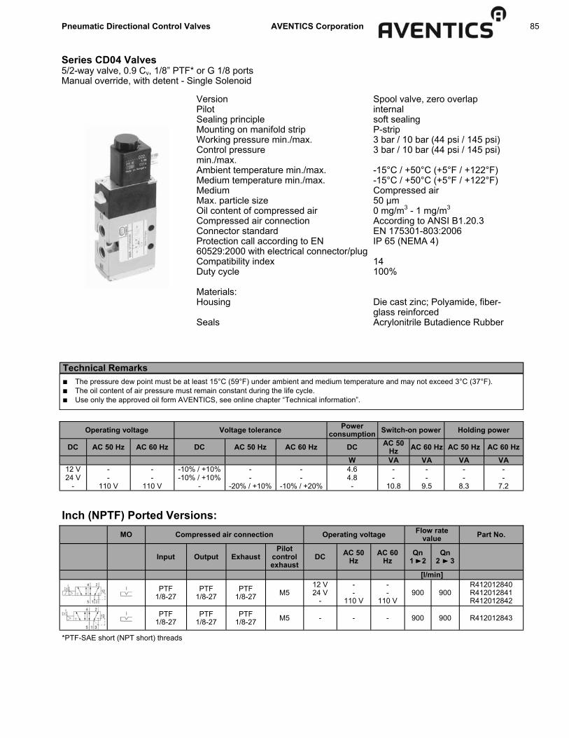
Pneumatic Directional Control Valves AVENTICS Corporation 85
Series CD04 Valves 5/2-way valve, 0.9 Cv, 1/8” PTF* or G 1/8 ports Manual override, with detent - Single Solenoid
Version Pilot Sealing principle Mounting on manifold strip Working pressure min./max. Control pressure min./max. Ambient temperature min./max. Medium temperature min./max. Medium Max. particle size Oil content of compressed air Compressed air connection Connector standard Protection call according to EN 60529:2000 with electrical connector/plug Compatibility index Duty cycle Materials: Housing Seals
Spool valve, zero overlap internal soft sealing P-strip 3 bar / 10 bar (44 psi / 145 psi) 3 bar / 10 bar (44 psi / 145 psi) -15°C / +50°C (+5°F / +122°F) -15°C / +50°C (+5°F / +122°F) Compressed air 50 µm 0 mg/m3 - 1 mg/m3 According to ANSI B1.20.3 EN 175301-803:2006 IP 65 (NEMA 4) 14 100% Die cast zinc; Polyamide, fiber-glass reinforced Acrylonitrile Butadience Rubber
Technical Remarks ■ The pressure dew point must be at least 15°C (59°F) under ambient and medium temperature and may not exceed 3°C (37°F). ■ The oil content of air pressure must remain constant during the life cycle. ■ Use only the approved oil form AVENTICS, see online chapter “Technical information”.
Operating voltage Voltage tolerance Power consumption Switch-on power
DC AC 50 Hz AC 60 Hz DC AC 50 Hz AC 60 Hz DC AC 50 Hz AC 60 Hz AC 50 Hz AC 60 Hz
W VA VA VA VA 12 V - - -10% / +10% - - 4.6 - - - - 24 V - - -10% / +10% - - 4.8 - - - -
- 110 V 110 V - -20% / +10% -10% / +20% - 10.8 9.5 8.3 7.2
Holding power
MO Compressed air connection Operating voltage Flow rate value Part No.
Input Output Exhaust Pilot
control exhaust
DC AC 50 Hz
AC 60 Hz
Qn 1 2
Qn 2 3
[l/min]
PTF 1/8-27
PTF 1/8-27
PTF 1/8-27 M5
12 V 24 V
-
- -
110 V
- -
110 V 900 900
R412012840 R412012841 R412012842
PTF 1/8-27
PTF 1/8-27
PTF 1/8-27 M5 - - - 900 900 R412012843
Inch (NPTF) Ported Versions:
*PTF-SAE short (NPT short) threads

86 Pneumatic Directional Control Valves AVENTICS Corporation
Series CD04 Valves 5/2-way valve, 0.9 Cv, 1/8” PTF* or G 1/8 ports Manual override, with detent - Single Solenoid
MO Compressed air connection Operating voltage Flow rate value Part No.
Input Output Exhaust Pilot
control exhaust
DC AC 50 Hz
AC 60 Hz
Qn 1 2
Qn 2 3
[l/min]
PTF 1/8-27
PTF 1/8-27
PTF 1/8-27 M5
12 V 24 V
-
- -
110 V
- -
110 V 900 900
R412012708 R412012709 R412012711
PTF 1/8-27
PTF 1/8-27
PTF 1/8-27 M5 - - - 900 900 R412012713
Inch (NPTF) Ported Versions (cont.):
Part No. Switch-on time Switch-off time Weight Note [ms] [ms] [kg]
R412012840 R412012841 R412012842
12 21 0.38 -
R412012843 12 21 0.33 1) R412012708 R412012709 R412012711
12 21 0.38 -
R412012713 12 21 0.33 1) MO = Manual override 1) Basic valve without coil Nominal flow Qn at 6 bar (87 psi) and ∆p = 1 bar (14.5 psi)
Metric (ISO G 1/8) Ported Versions: MO Compressed air connection Operating voltage Flow rate value Part No.
Input Output Exhaust Pilot
connec-tion
Pilot control exhaust
DC AC 50 Hz
AC 60 Hz Qn Qn
1 2
G 1/8 G 1/8 G 1/8 - M5
12 V 24 V
- - -
- -
110 V 230 V 24 V
- -
110 V 230 V 24 V
900 900
5777050210 5777050220 5777055270 5777055280 5777055220
G 1/8 G 1/8 G 1/8 - M5 - - - 900 900 5777055302
G 1/8 G 1/8 G 1/8 G 1/8 M5 24 V
- - -
- 110 V 230 V 24 V
- 110 V 230 V 24 V
900 900 5777060220 5777065270 5777065280 5777065220
G 1/8 G 1/8 G 1/8 G 1/8 M5 - - - 900 900 5777065302
G 1/8 G 1/8 G 1/8 - M5 24 V -
- 110 V
- 110 V 900 900 5777150220
5777155270
[l/min]

Pneumatic Directional Control Valves AVENTICS Corporation 87
Series CD04 Valves 5/2-way valve, 0.9 Cv, 1/8” PTF* or G 1/8 ports Manual override, with detent - Single Solenoid
Metric (ISO G 1/8) Ported Versions (cont.): Part No. Flow rate value Working pres-
sure min./max. Switch-on time Switch-off time Weight Note
Qn 2 3
[l/min] [bar] [ms] [ms] [kg] 5777050210 5777050220 5777055270 5777055280 5777055220
900 3 / 10 12 21 0.39 1)
5777055302 900 3 / 10 - - 0.34 1); 3) 5777060220 5777065270 5777065280 5777065220
900 -0.95 / 10 12 21 0.39 2)
5777065302 900 -0.95 / 10 - - 0.34 2); 3) 5777150220 5777155270 900 3 / 10 12 21 0.39 1)
MO = Manual override 1) Pilot: internal 2) Pilot: external 3) Basic valve without coil Nominal flow Qn at 6 bar and ∆p = 1 bar
Dimensions mm (Ports 1/8” PTF or ISO G1/8)
1) Metric version only with external pilot control G1/8 2) Coil can be rotated at 90° internals 3) After removal of cap M5 internal thread M5 4) Electrical connector can be plugged at 180° intervals 5) Manual override

88 Pneumatic Directional Control Valves AVENTICS Corporation
Series CD04 Valves 5/2-way valve, 0.9 Cv, 1/8” PTF* or G 1/8 ports Manual override, with detent - Double Solenoid
Version Pilot Sealing principle Mounting on manifold strip Working pressure min./max. Control pressure min./max. Ambient temperature min./max. Medium temperature min./max. Medium Max. particle size Oil content of compressed air Compressed air connection Connector standard Protection call according to EN 60529:2000 with electrical connector/plug Compatibility index Duty cycle Materials: Housing Seals
Spool valve, zero overlap internal soft sealing P-strip 2 bar / 10 bar (29 psi / 145 psi) 2 bar / 10 bar (29 psi / 145 psi) -15°C / +50°C (+5°F / +122°F) -15°C / +50°C (+5°F / +122°F) Compressed air 50 µm 0 mg/m3 - 1 mg/m3 According to ANSI B1.20.3 EN 175301-803:2006 IP 65 (NEMA 4) 14 100% Die cast zinc; Polyamide, fiber-glass reinforced Acrylonitrile Butadience Rubber
Technical Remarks ■ The pressure dew point must be at least 15°C (59°F) under ambient and medium temperature and may not exceed 3°C (37°F). ■ The oil content of air pressure must remain constant during the life cycle. ■ Use only the approved oil form AVENTICS, see online chapter “Technical information”.
Operating voltage Voltage tolerance Power consumption Switch-on power
DC AC 50 Hz AC 60 Hz DC AC 50 Hz AC 60 Hz DC AC 50 Hz AC 60 Hz AC 50 Hz AC 60 Hz
W VA VA VA VA 12 V - - -10% / +10% - - 4.6 - - - - 24 V - - -10% / +10% - - 4.8 - - - -
- 110 V 110 V - -20% / +10% -10% / +20% - 10.8 9.5 8.3 7.2
Holding power
MO Compressed air connection Operating voltage Flow rate value Part No.
Input Output Exhaust Pilot con-
trol ex-haust
DC AC 50 Hz AC 60 Hz Qn 1 2
Qn 2 3
[l/min]
PTF 1/8-27
PTF 1/8-27
PTF 1/8-27 M5
12 V 24 V
-
- -
110 V
- -
110 V 900 900
R412012999 R412013000 R412013001
PTF 1/8-27
PTF 1/8-27
PTF 1/8-27 M5 - - - 900 900 R412013002
Inch (NPTF) Ported Versions:
*PTF-SAE short (NPT short) threads

Pneumatic Directional Control Valves AVENTICS Corporation 89
Series CD04 Valves 5/2-way valve, 0.9 Cv, 1/8” PTF* or G 1/8 ports Manual override, with detent - Double Solenoid
Inch (NPTF) Ported Versions (cont.): Part No. Switch-on time Switch-off time Weight Note
[ms] [ms] [kg]
R412012999 R412013000 R412013001
12 21 0.46 -
R412013002 12 21 0.36 1) MO = Manual override 1) Basic valve without coil Nominal flow Qn at 6 bar (87 psi) and ∆p = 1 bar (14.5 psi)
Metric (ISO G 1/8) Ported Versions: MO Compressed air connection Operating voltage Flow rate value Part No.
Input Output Exhaust Pilot
connec-tion
Pilot control exhaust
DC AC 50 Hz
AC 60 Hz Qn Qn
1 2
[l/min]
G 1/8 G 1/8 G 1/8 - M5
12 V 24 V
- - -
- -
24 V 110 V 230 V
- -
24 V 110 V 230 V
900 900
R412008841 5777250220 5777255220 5777255270 5777255280
MO Compressed air connection Operating voltage Flow rate value Part No.
Input Output Exhaust Pilot
connec-tion
Pilot control exhaust
DC AC 50 Hz
AC 60 Hz Qn Qn
1 2
[l/min]
G 1/8 G 1/8 G 1/8 - M5 - - - 900 900 5777255302
G 1/8 G 1/8 G 1/8 G 1/8 M5 24 V -
- 230 V
- 230 V 900 900 5777260220
5777265280
G 1/8 G 1/8 G 1/8 G 1/8 M5 - - - 900 900 5777265302
Part No. Flow rate value Working pressure min./max. Switch-on time Switch-off time Weight Note
Qn 2 3
[l/min] [bar] [ms] [ms] [kg] R412008841 5777250220 5777255220 5777255270 5777255280
900 2 / 10 12 12 0.49 1)
5777055302 900 2 / 10 - - 0.36 1); 3)
5777260220 5777265280 900 -0.95 / 10 12 12 0.5 2)
5777065302 900 -0.95 / 10 - - 0.36 2); 3) MO = Manual override 1) Pilot: internal 2) Pilot: external 3) Basic valve without coil Nominal flow Qn at 6 bar and ∆p = 1 bar

90 Pneumatic Directional Control Valves AVENTICS Corporation
Series CD04 Valves 5/2-way valve, 0.9 Cv, 1/8” PTF* or G 1/8 ports Manual override, with detent - Double Solenoid
Dimensions mm (Ports 1/8” PTF or ISO G1/8)
1) Metric version only with external pilot control G1/8 2) Coil can be rotated at 90° internals 3) After removal of cap M5 internal thread M5 4) Electrical connector can be plugged at 180° intervals 5) Manual override

Pneumatic Directional Control Valves AVENTICS Corporation 91
Series CD04 Valves 5/3-way valve, 0.9 Cv, 1/8” PTF* or G 1/8 ports Manual override, with detent - Double Solenoid
Version Pilot Sealing principle Mounting on manifold strip Working pressure min./max. Control pressure min./max. Ambient temperature min./max. Medium temperature min./max. Medium Max. particle size Oil content of compressed air Compressed air connection Connector standard Protection call according to EN 60529:2000 with electrical connector/plug Compatibility index Duty cycle Materials: Housing Seals
Spool valve, zero overlap internal soft sealing P-strip 3.5 bar / 10 bar (51 psi / 145 psi) 3.5 bar / 10 bar (51 psi / 145 psi) -15°C / +50°C (+5°F / +122°F) -15°C / +50°C (+5°F / +122°F) Compressed air 50 µm 0 mg/m3 - 1 mg/m3 According to ANSI B1.20.3 EN 175301-803:2006 IP 65 (NEMA 4) 14 100% Die cast zinc; Polyamide, fiber-glass reinforced Acrylonitrile Butadience Rubber
Technical Remarks ■ The pressure dew point must be at least 15°C (59°F) under ambient and medium temperature and may not exceed 3°C (37°F). ■ The oil content of air pressure must remain constant during the life cycle. ■ Use only the approved oil form AVENTICS, see online chapter “Technical information”.
Operating voltage Voltage tolerance Power consumption Switch-on power
DC AC 50 Hz AC 60 Hz DC AC 50 Hz AC 60 Hz DC AC 50 Hz AC 60 Hz AC 50 Hz AC 60 Hz
W VA VA VA VA 12 V - - -10% / +10% - - 4.6 - - - - 24 V - - -10% / +10% - - 4.8 - - - -
- 110 V 110 V - -20% / +10% -10% / +20% - 10.8 9.5 8.3 7.2
Holding power
MO Compressed air connection Operating voltage Flow rate value Part No.
Input Output Exhaust Pilot con-
trol ex-haust
DC AC 50 Hz
AC 60 Hz
Qn 1 2
Qn 2 3
[l/min]
PTF 1/8-27
PTF 1/8-27
PTF 1/8-27 M5
12 V 24 V
-
- -
110 V
- -
110 V 900 900
R412013018 R412013019 R412013020
PTF 1/8-27
PTF 1/8-27
PTF 1/8-27 M5 - - - 900 900 R412012852
PTF 1/8-27
PTF 1/8-27
PTF 1/8-27 M5
12 V 24 V
-
- -
110 V
- -
110 V 900 900
R412013015 R412013016 R412013017
Qn
900
900
900
Inch (NPTF) Ported Versions:
*PTF-SAE short (NPT short) threads

92 Pneumatic Directional Control Valves AVENTICS Corporation
Series CD04 Valves 5/3-way valve, 0.9 Cv, 1/8” PTF* or G 1/8 ports Manual override, with detent - Double Solenoid
MO Compressed air connection Operating voltage Flow rate value Part No.
Input Output Exhaust Pilot con-
trol ex-haust
DC AC 50 Hz AC 60 Hz Qn
1 2 Qn
2 3
[l/min]
PTF 1/8-27
PTF 1/8-27
PTF 1/8-27 M5 - - - 900 900 R412012861
PTF 1/8-27
PTF 1/8-27
PTF 1/8-27 M5
12 V 24 V
-
- -
110 V
- -
110 V 900 900
R412013011 R412013012 R412013014
PTF 1/8-27
PTF 1/8-27
PTF 1/8-27 M5 - - - 900 900 R412012858
Qn
900
900
900
Inch (NPTF) Ported Versions (cont.):
Part No. Switch-on time Switch-off time Weight Note [ms] [ms] [kg]
R412013018 R412013019 R412013020
12 27 0.49 -
R412012852 12 27 0.39 1)
R412012858 12 27 0.39 1)
R412013011 R412013012 R412013014
12 27 0.49 -
R412012861 12 27 0.39 1)
R412013015 R412013016 R412013017
12 27 0.49 -
MO = Manual override 1) Basic valve without coil Nominal flow Qn at 6 bar (87 psi) and ∆p = 1 bar (14.5 psi)
Metric (ISO G 1/8) Ported Versions: MO Compressed air connection Operating voltage Flow rate value Part No.
Input Output Exhaust Pilot
control exhaust
DC AC 50 Hz
AC 60 Hz Qn Qn
1 2 Qn
2 3
G 1/8 G 1/8 G 1/8 M5 24 V -
- 230 V
- 230 V 900 900 900 5777420220
5777425280
G 1/8 G 1/8 G 1/8 M5 - - - 900 900 900 5777425302
G 1/8 G 1/8 G 1/8 M5 24 V -
- 230 V
- 230 V 900 900 900 5777410220
5777415280
G 1/8 G 1/8 G 1/8 M5 - - - 900 900 900 5777415302
G 1/8 G 1/8 G 1/8 M5 24 V -
- 230 V
- 230 V 900 900 900 5777400220
5777405280
G 1/8 G 1/8 G 1/8 M5 - - - 900 900 900 5777405302
[l/min]
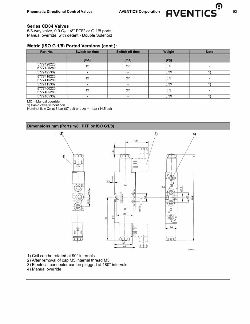
Pneumatic Directional Control Valves AVENTICS Corporation 93
Series CD04 Valves 5/3-way valve, 0.9 Cv, 1/8” PTF* or G 1/8 ports Manual override, with detent - Double Solenoid
Metric (ISO G 1/8) Ported Versions (cont.): Part No. Switch-on time Switch-off time Weight Note
[ms] [ms] [kg]
5777420220 5777425280 12 27 0.5 -
5777425302 - - 0.39 1)
5777405302 - - 0.39 1)
5777400220 5777405280 12 27 0.5 -
5777415302 - - 0.39 1)
5777410220 5777415280 12 27 0.5 -
MO = Manual override 1) Basic valve without coil Nominal flow Qn at 6 bar (87 psi) and ∆p = 1 bar (14.5 psi)
Dimensions mm (Ports 1/8” PTF or ISO G1/8)
1) Coil can be rotated at 90° internals 2) After removal of cap M5 internal thread M5 3) Electrical connector can be plugged at 180° intervals 4) Manual override

94 Pneumatic Directional Control Valves AVENTICS Corporation
Series CD04 Valves Electrical accessories - Electrical connector
Electrical connectors, Series CN1 ISO 6952 Electrical connector, form B
Ambient temperature min./max. -25°C / +40°C Protection class according to EN 60529: IP 65 Cable fitting M16x1,5 Mounting screw tightening torque 0.4 Nm
Max. current Contact assignment Cable exit Protection
circuit Suitable cable-
Ø min./max. Part No.
DC AC [V] [V] [A] [mm]
230 230 10 2+E angled 90° - 5 / 8 1834484096
24 24 - 2+E angled 90° Z-diode 5 / 8 1834484104
- 110
230
- 2+E angled 90° Varistor 5 / 8 1834484105
1834484106
Operating voltage
Part No. Number of plug options 1 LED status display Housing color Weight Note [kg]
1834484096 2 positions each 180° - Black 0.02 Fig. 1 1834484104 2 positions each 180° Yellow Transparent 0.02 Fig. 2 1834484105 1834484106 2 positions each 180° Red Transparent 0.02 Fig. 2
Fig. 1 Fig. 2

Pneumatic Directional Control Valves AVENTICS Corporation 95
Series CD04 Valves Electrical accessories - Electrical connector, with cable
Electrical connectors, Series CN1 ISO 6952 Electrical connector, form B with cable
Ambient temperature min./max. -20°C / +80°C Protection class according to EN 60529: IP 67 Cable exit angled 90° Tightening torque for mounting screws 0.4 Nm
Electrical interface
Number of plug options Max. current Protective
circuit Contact
assignment Part No
[Port 1] [for port 1] [V DC] [V AC] [A]
Electrical
connector, form B
1 position 230 230 10 - 2+E 1834484148 1834484149 1834484150 1834484151
Electrical
connector, form B
1 position 24 24 10 Z-diode 2+E 1834484152 1834484153 1834484154 1834484155
Electrical
connector, form B
1 position 230 230 10 Varistor 2+E 1834484156 1834484157 1834484158 1834484159
Operating voltage
Part No. LED status display Housing color Cable length Weight Note [m] [kg]
1834484148 1834484149 1834484150 1834484151
- Black 3 3 5 5
0.2 0.2
0.31 0.31
Fig. 1 Fig. 2 Fig. 1 Fig. 2
1834484152 1834484153 1834484154 1834484155
Yellow Black 3 3 5 5
0.2 0.2
0.31 0.31
Fig. 3 Fig. 4 Fig. 3 Fig. 4
1834484156 1834484157 1834484158 1834484159
Red Black 3 3 5 5
0.2 0.2
0.31 0.31
Fig. 3 Fig. 4 Fig. 3 Fig. 4
Fig. 1 Fig. 2
1) 0° female insert 2) 180° female insert
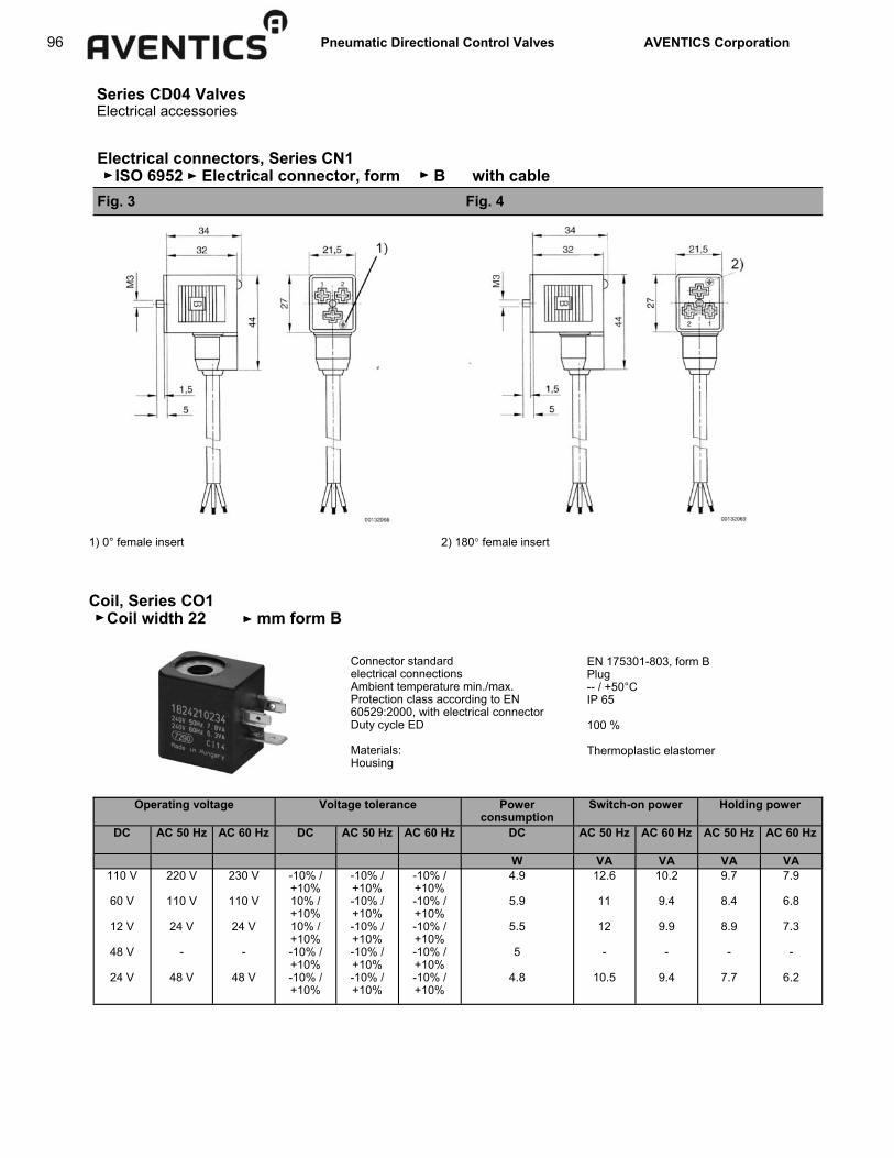
96 Pneumatic Directional Control Valves AVENTICS Corporation
Series CD04 Valves Electrical accessories
Electrical connectors, Series CN1 ISO 6952 Electrical connector, form B with cable Fig. 3 Fig. 4
1) 0° female insert 2) 180° female insert
Coil, Series CO1 Coil width 22 mm form B
Connector standard electrical connections Ambient temperature min./max. Protection class according to EN 60529:2000, with electrical connector Duty cycle ED Materials: Housing
EN 175301-803, form B Plug -- / +50°C IP 65 100 % Thermoplastic elastomer
Operating voltage Voltage tolerance Power consumption
Switch-on power
DC AC 50 Hz AC 60 Hz DC AC 50 Hz AC 60 Hz DC AC 50 Hz AC 60 Hz AC 50 Hz AC 60 Hz
W VA VA VA VA 110 V
60 V
12 V
48 V
24 V
220 V
110 V
24 V -
48 V
230 V
110 V
24 V -
48 V
-10% / +10% 10% / +10% 10% / +10% -10% / +10% -10% / +10%
-10% / +10% -10% / +10% -10% / +10% -10% / +10% -10% / +10%
-10% / +10% -10% / +10% -10% / +10% -10% / +10% -10% / +10%
4.9
5.9
5.5
5
4.8
12.6
11
12 -
10.5
10.2
9.4
9.9 -
9.4
9.7
8.4
8.9 -
7.7
7.9
6.8
7.3 -
6.2
Holding power

Pneumatic Directional Control Valves AVENTICS Corporation 97
Series CD04 Valves Electrical accessories/Silencers
Coil, Series CO1 (cont.) Coil width 22 mm form B
Compatibility index Weight Part No.
DC AC 50 Hz AC 60 Hz [kg]
110 V 60 V 12 V 48 V 24 V
220 V 110 V 24 V
- 48 V
230 V 110 V 24 V
- 48 V
14 0.07
1824210235 1824210237 1824210239 1824210241 1824210243
Operating voltage
Dimensions
Silencers 1/8” NPTF or ISO G 1/8 threads
Part No. Threads Type Order Multiple* Length R432012062 1/8” NPTF Silencer, metal 1 1.38” 1827000000 G 1/8 Silencer, sintered bronze/brass, series SI1, conical 10 24 mm 1827000031 G 1/8 Silencer, sintered bronze/brass, series SI1, flat 10 11.5 mm 1827430004 G 1/8 Silencer, sintered bronze/brass, series SI1, recessed in port 10 4 mm 1827000019 G 1/8 Silencer, polyethylene, series SI1 5 34 mm
*Due to bag quantity, this is the order multiple per part number.

98 Pneumatic Directional Control Valves AVENTICS Corporation
Series CD04 Valves 3/2-way valve, 0.9 Cv, 1/8” PTF* or G 1/8 ports Air Pilot
Version Sealing principle Working pressure min./max. Control pressure min./max. Ambient temperature min./max. Medium temperature min./max. Medium Max. particle size Oil content of compressed air Compressed air connection Material: Housing Seals
Spool Valve, zero overlap soft sealing -0.95 bar / 10 bar (-14 psi / 145 psi) 3.5 bar / 10 bar (51 psi / 145 psi) -15°C / +50°C (+5°F / +122°F) -15°C / +50°C (+5°F / +122°F) Compressed air 50µm 0 mg/m3 - 1 mg/m3 according to ANSI B1.20.3 Die cast zinc; Polyamide, fiber-glass reinforced Acrylonitrile Butadiene Rubber
Technical Remarks ■ The pressure dew point must be at least 15°C (59°F) under ambient and medium temperature and may not exceed 3°C (37°F). ■ The oil content of air pressure must remain constant during the life cycle. ■ Use only the approved oil form AVENTICS, see online chapter “Technical information”.
Compressed air connection Flow rate value
Input Output Exhaust Pilot connection Qn Qn
1 2 Qn
2 3 Weight Part No.
[kg]
NO/NC PTF 1/8-27
PTF 1/8-27
PTF 1/8-27
PTF 1/8-27 900 900 900 0.29 R412013298
NO/NC G 1/8 G 1/8 G 1/8 G 1/8 900 900 900 0.29 5710200100
[l/min]
Dimensions in inches
Nominal flow Qn at 6 bar (87 psi) and ∆p = 1 bar (14.5 psi)
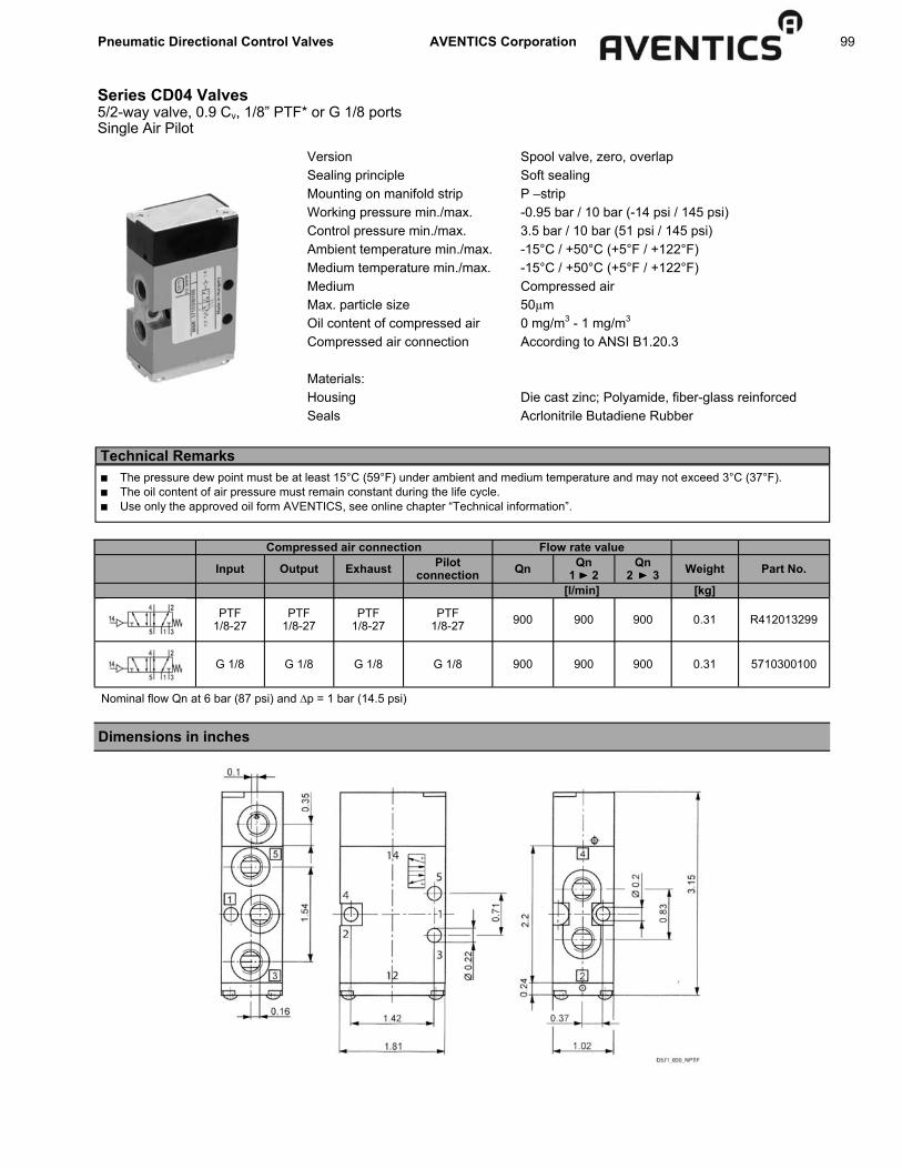
Pneumatic Directional Control Valves AVENTICS Corporation 99
Series CD04 Valves 5/2-way valve, 0.9 Cv, 1/8” PTF* or G 1/8 ports Single Air Pilot
Compressed air connection Flow rate value
Input Output Exhaust Pilot connection Qn Qn
1 2 Qn
2 3 Weight Part No.
[l/min] [kg]
PTF 1/8-27
PTF 1/8-27
PTF 1/8-27
PTF 1/8-27 900 900 900 0.31 R412013299
G 1/8 G 1/8 G 1/8 G 1/8 900 900 900 0.31 5710300100
Version Spool valve, zero, overlap Sealing principle Soft sealing Mounting on manifold strip P –strip Working pressure min./max. -0.95 bar / 10 bar (-14 psi / 145 psi) Control pressure min./max. 3.5 bar / 10 bar (51 psi / 145 psi) Ambient temperature min./max. -15°C / +50°C (+5°F / +122°F) Medium temperature min./max. -15°C / +50°C (+5°F / +122°F) Medium Compressed air Max. particle size 50µm Oil content of compressed air 0 mg/m3 - 1 mg/m3 Compressed air connection According to ANSI B1.20.3 Materials: Housing Die cast zinc; Polyamide, fiber-glass reinforced Seals Acrlonitrile Butadiene Rubber
Dimensions in inches
Technical Remarks ■ The pressure dew point must be at least 15°C (59°F) under ambient and medium temperature and may not exceed 3°C (37°F). ■ The oil content of air pressure must remain constant during the life cycle. ■ Use only the approved oil form AVENTICS, see online chapter “Technical information”.
Nominal flow Qn at 6 bar (87 psi) and ∆p = 1 bar (14.5 psi)

100 Pneumatic Directional Control Valves AVENTICS Corporation
Series CD04 Valves 5/2-way valve, 0.9 Cv, 1/8” PTF* or G 1/8 ports Double Air Pilot
Version Sealing principle Mounting on manifold strip Working pressure min./max. Control pressure min./max. Ambient temperature min./max. Medium temperature min./max. Medium Max. particle size Oil content of compressed air Compressed air connection Materials: Housing Seals
Spool valve, zero overlap soft sealing P-strip -0.95 bar / 10 bar (-14 psi / 145 psi) 2 bar / 10 bar (29 psi / 145 psi) -15°C / +50°C (+5°F / +122°F) -15°C / +50°C (+5°F / +122°F) Compressed air 50 µm 0 mg/m3 - 1 mg/m3 according to ANSI B1.20.3 Die cast zinc; Polyamide, fiber-glass reinforced Acrylonitrile Butadience Rubber
Technical Remarks ■ The pressure dew point must be at least 15°C (59°F) under ambient and medium temperature and may not exceed 3°C (37°F). ■ The oil content of air pressure must remain constant during the life cycle. ■ Use only the approved oil form AVENTICS, see online chapter “Technical information”.
Compressed air connection Flow rate value
Input Output Exhaust Pilot con-nection Qn Qn
1 2 Qn
2 3 Weight Part No.
[l/min] [kg]
PTF 1/8-27
PTF 1/8-27
PTF 1/8-27
PTF 1/8-27 900 900 900 0.3 R412013300
G 1/8 G 1/8 G 1/8 G 1/8 900 900 900 0.3 5710301100
Dimensions in inches
Nominal flow Qn at 6 bar (87 psi) and ∆p = 1 bar (14.5 psi)

Pneumatic Directional Control Valves AVENTICS Corporation 101
Series CD04 Valves 3/2-way valve, 0.9 Cv, 1/8” PTF* or G 1/8 ports Mechanically Operated
Version Sealing principle Working pressure min./max. Ambient temperature min./max. Medium temperature min./max. Medium Max. particle size Oil content of compressed air Compressed air connection Materials: Housing Seals
Spool valve, zero overlap soft sealing -0.95 bar / 10 bar (-14 psi / 145 psi) -15°C / +50°C (+5°F / +122°F) -15°C / +50°C (+5°F / +122°F) Compressed air 50 µm 0 mg/m3 - 1 mg/m3 according to ANSI B1.20.3 Die cast zinc; Polyamide, fiber-glass reinforced Acrylonitrile Butadience Rubber
Technical Remarks ■ The pressure dew point must be at least 15°C (59°F) under ambient and medium temperature and may not exceed 3°C (37°F). ■ The oil content of air pressure must remain constant during the life cycle. ■ Use only the approved oil form AVENTICS, see online chapter “Technical information”.
Inch (PTF) Ported Versions: Control
element Version Qn Qn 1 2
Qn 2 3 Part No.
Input Output Exhaust [l/min] [l/min] [l/min]
Plunger NC/NO PTF 1/8-27
PTF 1/8-27
PTF 1/8-27 900 900 900 R412013026
Roller NC/NO PTF 1/8-27
PTF 1/8-27
PTF 1/8-27 900 900 900 R412013021
R412013022
Hand lever, with detent,
without detent NC/NO PTF
1/8-27 PTF
1/8-27 PTF
1/8-27 900 900 900 R412013025
Hand lever NC/NO PTF 1/8-27
PTF 1/8-27
PTF 1/8-27 900 900 900 R412013023
Rotary lever, with detent NC/NO PTF
1/8-27 PTF
1/8-27 PTF
1/8-27 900 900 900 R412013024
Button NC/NO PTF 1/8-27
PTF 1/8-27
PTF 1/8-27 900 900 900 R412013027
Compressed air connection
Part No. Operating force Min. Material: Actuating control Weight Note [N] [kg]
R412013026 60 Stainless steel 0.23 Fig. 1 R412013021 R412013022 30 Polyoxymethylene Stainless
steel 0.29 Fig. 2
R412013025 15 Polyoxymethylene 0.32 Fig. 3 R412013023 15 Aluminum 0.29 Fig. 4 R412013024 15 Stainless steel; Plastic 0.5 Fig. 5 R412013027 60 Polyoxymethylene 0.25 Fig. 6
Nominal flow Qn at 6 bar (87 psi) and ∆p = 1 bar (14.5 psi)
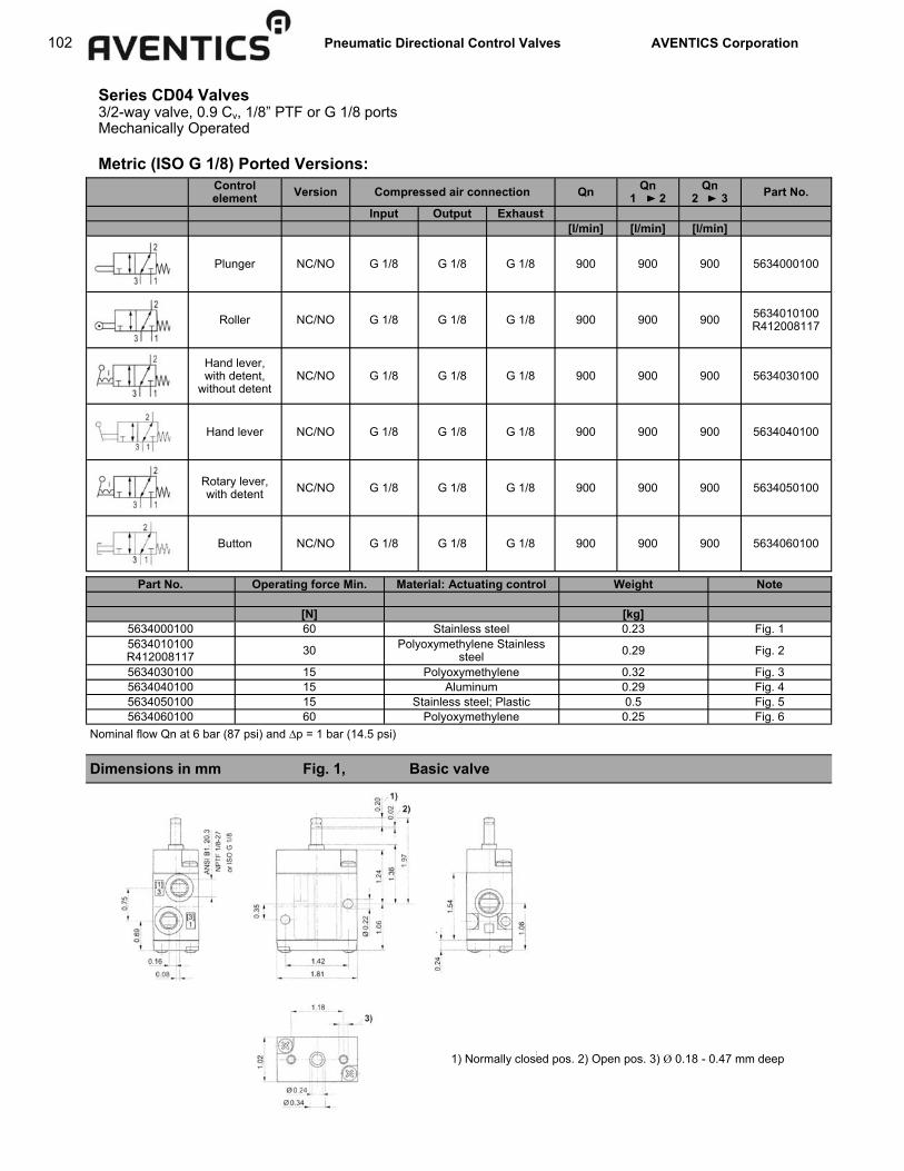
102 Pneumatic Directional Control Valves AVENTICS Corporation
Series CD04 Valves 3/2-way valve, 0.9 Cv, 1/8” PTF or G 1/8 ports Mechanically Operated
Control element Version Qn Qn
1 2 Qn
2 3 Part No.
Input Output Exhaust [l/min] [l/min] [l/min]
Plunger NC/NO G 1/8 G 1/8 G 1/8 900 900 900 5634000100
Roller NC/NO G 1/8 G 1/8 G 1/8 900 900 900 5634010100 R412008117
Hand lever, with detent,
without detent NC/NO G 1/8 G 1/8 G 1/8 900 900 900 5634030100
Hand lever NC/NO G 1/8 G 1/8 G 1/8 900 900 900 5634040100
Rotary lever, with detent NC/NO G 1/8 G 1/8 G 1/8 900 900 900 5634050100
Button NC/NO G 1/8 G 1/8 G 1/8 900 900 900 5634060100
Compressed air connection
Metric (ISO G 1/8) Ported Versions:
Part No. Operating force Min. Material: Actuating control Weight Note [N] [kg]
5634000100 60 Stainless steel 0.23 Fig. 1 5634010100 R412008117 30 Polyoxymethylene Stainless
steel 0.29 Fig. 2
5634030100 15 Polyoxymethylene 0.32 Fig. 3 5634040100 15 Aluminum 0.29 Fig. 4 5634050100 15 Stainless steel; Plastic 0.5 Fig. 5 5634060100 60 Polyoxymethylene 0.25 Fig. 6
Nominal flow Qn at 6 bar (87 psi) and ∆p = 1 bar (14.5 psi)
Dimensions in mm Fig. 1, Basic valve
1) Normally closed pos. 2) Open pos. 3) Ø 0.18 - 0.47 mm deep

Pneumatic Directional Control Valves AVENTICS Corporation 103
Series CD04 Valves 3/2-way valve, 0.9 Cv, 1/8” PTF or G 1/8 ports Mechanically Operated
Dimensions in inches Fig. 2
Dimensions in inches Fig. 3
1) Approach angle of rollers max. 30° 2) Normally closed pos. 3) Open pos. 4) POM versions 0.79” dia. / stainless steel versions 0.75” dia. Dimensions of basic valve apply to all types of actuation.
Position 0: initial position Position I: automatic spring return Position II: with detent, manual return. Dimensions of basic valve apply to all types of actuation.

104 Pneumatic Directional Control Valves AVENTICS Corporation
Dimensions of basic valve apply to all types of actuation.
Dimensions in inches Fig. 4
Dimensions in inches Fig. 5
Series CD04 Valves 3/2-way valve, 0.9 Cv, 1/8” PTF or G 1/8 ports Mechanically Operated
Dimensions of basic valve apply to all types of actuation.

Pneumatic Directional Control Valves AVENTICS Corporation 105
Dimensions in inches Fig. 6
Series CD04 Valves 3/2-way valve, 0.9 Cv, 1/8” PTF or G 1/8 ports Mechanically Operated
1) Normally closed pos. 2) Open pos. 3) Ø 0.18 - 0.47 in. deep Dimensions of basic valve apply to all types of actuation.

106 Pneumatic Directional Control Valves AVENTICS Corporation
Series CD04 Valves 5/2-way valve, 0.9 Cv, 1/8” PTF or G 1/8 ports Mechanically Operated
Version Sealing principle Working pressure min./max. Ambient temperature min./max. Medium temperature min./max. Medium Max. particle size Oil content of compressed air Compressed air connection Materials: Housing Seals
Spool valve, zero overlap soft sealing -0.95 bar / 10 bar (-14 psi / 145 psi) -15°C / +50°C (+5°F / +122°F) -15°C / +50°C (+5°F / +122°F) Compressed air 50 µm 0 mg/m3 - 1 mg/m3 according to ANSI B1.20.3 Die cast zinc; Polyamide, fiber-glass rein-forced Acrylonitrile Butadience Rubber
Technical Remarks ■ The pressure dew point must be at least 15°C (59°F) under ambient and medium temperature and may not exceed 3°C (37°F). ■ The oil content of air pressure must remain constant during the life cycle. ■ Use only the approved oil form AVENTICS, see online chapter “Technical information”.
Inch (PTF) Ported Versions: Control
element Compressed air connection Qn Qn 1 2
Qn 2 3 Part No.
Input Output Exhaust [l/min] [l/min] [l/min]
Plunger PTF 1/8-27
PTF 1/8-27
PTF 1/8-27 900 900 900 R412013032
Roller PTF 1/8-27
PTF 1/8-27
PTF 1/8-27 900 900 900 R412013028
Hand lever, with detent,
without detent PTF
1/8-27 PTF
1/8-27 PTF
1/8-27 900 900 900 R412013031
Hand lever PTF 1/8-27
PTF 1/8-27
PTF 1/8-27 900 900 900 R412013029
Rotary lever, with detent
PTF 1/8-27
PTF 1/8-27
PTF 1/8-27 900 900 900 R412013030
Button PTF 1/8-27
PTF 1/8-27
PTF 1/8-27 900 900 900 R412013033
Operating force Min.
[N]
70
35
15
60
20
70
Part No. Material: Actuating control Weight Note [kg]
R412013032 Stainless steel 0.29 Fig. 1 R412013028 Polyoxymethylene 0.35 Fig. 2 R412013031 Polyoxymethylene 0.38 Fig. 3 R412013029 Aluminum 0.36 Fig. 4 R412013030 Stainless steel; Plastic 0.56 Fig. 5 R412013033 Polyoxymethylene 0.32 Fig. 6
Nominal flow Qn at 6 bar (87 psi) and ∆p = 1 bar (14.5 psi)
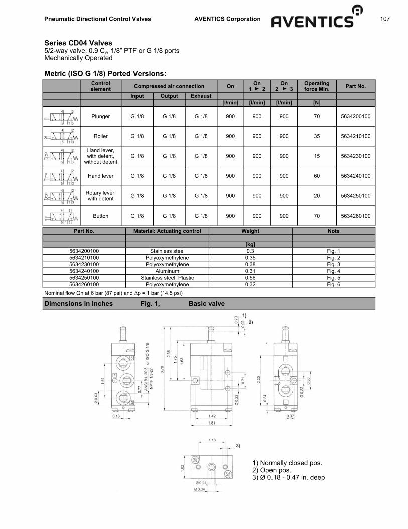
Pneumatic Directional Control Valves AVENTICS Corporation 107
Control element Compressed air connection Qn Qn
1 2 Qn
2 3 Part No.
Input Output Exhaust [l/min] [l/min] [l/min]
Plunger G 1/8 G 1/8 G 1/8 900 900 900 5634200100
Roller G 1/8 G 1/8 G 1/8 900 900 900 5634210100
Hand lever, with detent,
without detent G 1/8 G 1/8 G 1/8 900 900 900 5634230100
Hand lever G 1/8 G 1/8 G 1/8 900 900 900 5634240100
Rotary lever, with detent G 1/8 G 1/8 G 1/8 900 900 900 5634250100
Button G 1/8 G 1/8 G 1/8 900 900 900 5634260100
Operating force Min.
[N]
70
35
15
60
20
70
Series CD04 Valves 5/2-way valve, 0.9 Cv, 1/8” PTF or G 1/8 ports Mechanically Operated
Metric (ISO G 1/8) Ported Versions:
Part No. Material: Actuating control Weight Note [kg]
5634200100 Stainless steel 0.3 Fig. 1 5634210100 Polyoxymethylene 0.35 Fig. 2 5634230100 Polyoxymethylene 0.38 Fig. 3 5634240100 Aluminum 0.31 Fig. 4 5634250100 Stainless steel; Plastic 0.56 Fig. 5 5634260100 Polyoxymethylene 0.32 Fig. 6
Nominal flow Qn at 6 bar (87 psi) and ∆p = 1 bar (14.5 psi)
Dimensions in inches Fig. 1, Basic valve
1) Normally closed pos. 2) Open pos. 3) Ø 0.18 - 0.47 in. deep

108 Pneumatic Directional Control Valves AVENTICS Corporation
1) Approach angle of rollers max. 30° 2) Normally closed pos. 3) Open pos. 4) POM versions 0.79” dia. / stainless steel versions 0.75” dia. Dimensions of basic valve apply to all types of actuation.
Series CD04 Valves 5/2-way valve, 0.9 Cv, 1/8” PTF or G 1/8 ports Mechanically Operated
Dimensions in inches Fig. 2
Dimensions in inches Fig. 3
Position 0: initial position Position I: automatic spring return Position II: with detent, manual return. Dimensions of basic valve apply to all types of actuation.

Pneumatic Directional Control Valves AVENTICS Corporation 109
Series CD04 Valves 5/2-way valve, 0.9 Cv, 1/8” PTF or G 1/8 ports Mechanically Operated
Dimensions in inches Fig. 4
Dimensions in inches Fig. 5 Fig. 6
Dimensions of basic valve apply to all types of actuation.
Dimensions of basic valve apply to all types of actuation.
1) Normally closed pos. 2) Open pos. 3) Ø 0.18 - 0.47 in. deep Dimensions of basic valve apply to all types of actuation.

110 Pneumatic Directional Control Valves AVENTICS Corporation
CD07 Valves, Solenoid and Air Pilot Specifications and features
ELECTRICAL DATA: Standard Voltage
(all coils are rated for continues duty) Power Consumption
Inrush Holding
110 VAC 50 Hz/120 VAC 60 Hz 24 VAC 50/60 Hz
6.4 VA 3.7 VA
12, 24 VDC 2.7 W
VOLTAGE TOLERENCE: +10% NOTE: Electrical connectors must be ordered separately. One per solenoid required, see Solenoid Connectors page.
All Standard valves are rated for NEMA 4. Brad Harrison® coils available - consult factory.
4 bank pressure port with 2 single solenoid valves and 2 double solenoid valves.
4 Way / 2 Position 1/4” NPT Solenoid & Air Pilot Operated TECHNICAL DATA: Port Sizes: 1/4” NPT Working Pressure: Vacuum service to 150 PSI Pilot Pressure: 22 PSI minimum - Double Solenoid & Double Air Pilot (2 position models) 45 PSI minimum - Single Solenoid & Single Air Pilot 45 PSI minimum - Double Solenoid & Double Air Pilot (3 position models) Dual pressure applications acceptable when external pilot supply is used. Flow: Cv 1.1 Temperature Range: Solenoid Valve +5°F to +120°F Air Pilot -20°F to + 175°F Explosion Proof Solenoid: 0° to +150°F Media: Air (either lubricated or non-lubricated)
Seals: Buna-N
Manual Override: Locking
FEATURES ■ The 1/4” 4-way, 5-ported CD07 Valve is an extremely
versatile, yet compact, design. This low-profile spool type design will not only enhance the appearance of your equipment, but will save valuable engineering space. A new simplified internal design allows for consistently reliable performance and ease of operation.
■ The CD07 Valve is available with a wide range of solenoid, air pilot and mechanical operators. This new design allows each valve body to be readily STACKED through a convenient and simplified single pressure port bar. Unique optional sole-noid connectors offer neon indicator lights for (AC) circuits and L.E.D. displays for (DC) circuits.
■ Standard Plug-In DIN Connection “Low wattage” (2.1W) solenoid and connector, available with
or without built-in indicator light. ■ External Pilot: (not shown) Allows an independent air supply
to be connected to the pilot port of the solenoid operator. ■ Manual Locking Overrides: Allow supplementary manual
control and permit operating the valve when the electric power is off.
■ Solenoid Coil Removal: Un-screw coil retaining nut and slip off the coil.
■ Seal Spacers: New lightweight acetal cartridge assembly. ■ Manifold System: Common pressure port bar

Pneumatic Directional Control Valves AVENTICS Corporation 111
CD07 Valves, Solenoid and Air Pilot Single and double solenoid, 5/2
*For all applications when supply pressure is 45 psi or higher. Use external pilot version if supply pressure is under 45 psi (including vacuum or dual pressure applications). Take care to note which version is required before ordering since internal/external conversion is not field convertible.
Single Solenoid 4-Way, 2 Position (less connector)
Part Number Old Part No. Description Part Number Old Part No. Description
*Internal Pilot: *Internal Pilot:
R432016582 PS-031010-01355 110V-50Hz/120V-60Hz R432016587 PS-032010-01313 110V-50Hz/120V-60Hz
R432016583 PS-031010-01655 220V-50Hz/240V-60Hz R432016589 PS-032010-01616 220V-50Hz/240V-60Hz
R432016585 PS-031010-07255 12 VDC R432016593 PS-032010-07272 12 VDC
R432016584 PS-031010-06955 24 VDC R432016591 PS-032010-06969 24 VDC
R432016586 PS-031010-07855 24 VAC-50/60Hz R432016595 PS-032010-07878 24 VAC-50/60Hz
External Pilot: External Pilot:
R432016605 PS-034010-01355 110V-50Hz/120V-60Hz R432016604 PS-034010-01313 110V-50Hz/120V-60Hz
R432016609 PS-034010-01655 220V-50Hz/240V-60Hz R432016608 PS-034010-01616 220V-50Hz/240V-60Hz
R432016615 PS-034010-07255 12 VDC R432016616 PS-034010-07272 12 VDC
R432016613 PS-034010-06955 24 VDC PS-034010-06969 24 VDC
R432016618 PS-034010-07855 24 VAC-50/60Hz PS-034010-07878 24 VAC-50/60Hz
Double Solenoid 4-Way, 2 Position (less connector)
4 Way / 2 Position 1/4” NPT Solenoid & Air Pilot Operated
SINGLE SOLENOID PLUG-IN (DIN) CONNECTION
DOUBLE SOLENOID PLUG-IN (DIN) CONNECTION
NOTE: All dimensions expressed in IN MM
.79 DIA.,02 DEEP [Ø 20.0] [0.5]
(5) PL’S.
.79 DIA.,02 DEEP [Ø 20.0] [0.5]
(5) PL’S.
1/4 - 1/8 NPTF .46 [11.7] DP (5) PLACES
1/4 - 1/8 NPTF .46 [11.7] DP (5) PLACES
.22 DIA. [Ø 5.5]
THRU(2) PL’S
.22 DIA. [Ø 5.5]
THRU(2) PL’S

112 Pneumatic Directional Control Valves AVENTICS Corporation
4 Way / 2 Position 1/4” NPT Explosion Proof Solenoid Valves for Hazardous Locations
CD07 Valves, Solenoid and Air Pilot Explosion proof and air pilot models
Single Air Pilot: Part Number R432016611 (Old Part No. PS-034010-03355)
Double Air Pilot: Part Number R432016610 (Old Part No. PS-034010-03333)
Model Part No. Coil Voltage
Single Solenoid R432032544 120 VAC 50/60 Hz
Single Solenoid R432032545 240 VAC 50/60 Hz
Double Solenoid R432032546 120 VAC 50/60 Hz
CSA: Class I, Zone 1, Ex m II T4 Class I, Div. 1, Gr. A, B, C and D Class II, GR. E, F and G, Class III; T4
FM: Class I, Zone 1, Aex m II T4 Class I, Div. 1, Gr. A, B, C and D Class II, GR. E, F and G, Class III; T4
4 Way / 2 Position 1/4” NPT Air Pilot Operated Valves

Pneumatic Directional Control Valves AVENTICS Corporation 113
4 Way / 3 Position, 1/4” NPT Double Solenoid and Air Pilot Operated
CD07 Valves, Solenoid and Air Pilot 5/3 double solenoid and double air pilot
Air Pilot Model Part No. Old Part No.
Closed Center R432016612 PS-034010-03535
Exh. Open Ctr. R432016619 PS-034020-03535
Supply Open Ctr. R432016620 PS-034030-03535
Double Sol., 3 Pos. Closed Center Exhaust Center
Coil Voltage Part No. Old Part No. Part No. Old Part No. Part No. Old Part No.
110V-50Hz/120V-60Hz R432016588 PS-032010-01515 R432016597 PS-032020-01515 R432016601 PS-032030-01515
220V-50Hz/240V-60Hz R432016590 PS-032010-01818 PS-032020-01818 PS-032030-01818
12 VDC R432016594 PS-032010-07474 R432016599 PS-032020-07474 R432030384 PS-032030-07474
24 VDC R432016592 PS-032010-07171 R432016598 PS-032020-07171 R432016602 PS-032030-07171
24 VAC-50/60Hz R432016596 PS-032010-07979 R432016600 PS-032020-07979 R432016603 PS-032030-07979
Supply Center

114 Pneumatic Directional Control Valves AVENTICS Corporation
CD07 Valves, Solenoid and Air Pilot Repair kits and parts
BODY REPAIR KIT BODY REPAIR KIT (Includes all rubber parts, 2 cartridges (Includes all rubber parts and 2 cartridges)
and 2 pilot piston assemblies) Part No. Old Part No. Description Part No. Old Part No. Description
R432008496 P -026235-00000 PS3…Series R432013712 P -067189-K0000 PS2Series (Obs. STACKMASTER)
SOLENOID PILOT OPERATOR KIT SOLENOID PLUNGER REPAIR KIT
(One per solenoid required) (Includes armature, plunger/spring and seal) Part No. Old Part No. Description Part No. Old Part No. Description
R432008497 P -026236-00000 Internal Pilot R432015687 P -069541-00000 PS3…Series Standard Models R432008657 P -026628-00000 External Pilot
SOLENOID KITS (Includes Complete Solenoid Operator and Coil)
INTERNAL PILOT Part No. Old Part No. Description R432008498 P -026240-00000 110V-50Hz/120V-60Hz R432008499 P -026241-00000 220V-50Hz/240V-60Hz R432008500 P -026242-00000 24 VAC 50/60Hz R432008501 P -026243-00000 12 VDC R432008502 P -026244-00000 24 VDC
SOLENOID COILS For Standard CD07 Valves For Explosion Proof CD07 Valves
Part Old Part Part Old Part Number Number Voltage Number Number Voltage R432011985 P -048835-00001 110V-50Hz/120V-60Hz R432013760 P -067370-00000 110V-50Hz/120V-60Hz R432011986 P -048835-00002 220V-50Hz/240V-60Hz R432013761 P -067371-00000 220V-50Hz/240V-60Hz R432011990 P -048835-00006 24 VAC 50/60Hz n/a P -067373-00000 24 VAC 50/60Hz * R432011988 P -048835-00004 12 VDC n/a P -067373-00000 12 VDC * R432011989 P -048835-00005 24 VDC R432013763 P -067374-00000 24 VDC * 12VDC is dual rated for 24VAC and 60Hz service. With these repair kits, the elastomer seals and some common wear parts on the component are renewed. On severely worn or damaged valves, additional parts may be required. For additional parts, information and service instructions, refer to Service Bulletin SM-300.30.

Pneumatic Directional Control Valves AVENTICS Corporation 115
CD07 Valves, Solenoid and Air Pilot Pressure port manifold bar
1/4” NPT Pressure Port Bar Manifold System for CD07 Valves Will accommodate a mixture of all types of CD07 valves and operators. However, the Rotary Lever, Plain Knob and Explosion Proof operators may not have operating clearance. How to Order: Select the valves or combination of CD07 valves. Then select the number of stations by the part number listed below:
No. of Stations
Part No. Old Part No.
2 R432015553 P -069258-00002 3 R432015554 P -069258-00003 4 R432015555 P -069258-00004 5 R432015556 P -069258-00005 6 R432015557 P -069258-00006 7 R432015558 P -069258-00007 8 R432015559 P -069258-00008
“A” IN/mm
3.62/92.0 4.84/123.0 6.06/154.0 7.28/185.0 8.50/216.0 9.72/247.0 10.94/278.0

116 Pneumatic Directional Control Valves AVENTICS Corporation
CD07 Valves, Manual & Mechanical Operators Specifications, features, pedal and rotary lever operators
4 Way / 2 Position 1/4” NPT Manual and Mechanical Operators TECHNICAL DATA: Port Sizes: 1/4 NPT Working Pressure: Vacuum service to 150 psi Can be used for dual pressure applications Flow: Cv = 1.1 Temperature Range: -20° to +175°F Media: Air (Lubricated or non-lubricated) Materials: Body: Zinc die casting Spools: Stainless Steel FEATURES: ■ The 1/4” 4-way, 5-ported CD07 valve is an extremely
versatile, yet compact design. This low profile spool type design will not only enhance the appearance of your equipment, but will save valuable engineering space
■ A simplified internal design allows for consistently reliable performance and ease of operation
Plunger (2-Position, Spring Return) Part No. R432016625 (Old Part No. PS-034040-05155)
NOTE: All dimensions expressed in IN MM
Part Number R432016624 (Old Part No. PS-034040-02255)

Pneumatic Directional Control Valves AVENTICS Corporation 117
CD07 Valves, Manual & Mechanical Operators Roller, one-way trip, toggle, paddle and plunger operators
Part Number R432016623 (Old Part No. PS-034040-00855)
4 Way / 2 Position 1/4” NPT Manual and Mechanical Operators Roller (2-Position, Spring Return)
Toggle (2-Position, Spring Return or Detented) Part Number R432016626 (Old Part No. PS-034040-05855) 60° Travel-Spring Rtn. 57° Travel-Detented
Paddle (2-Position, Spring Return) Part Number R432016621 (Old Part No. PS-034040-00255)
NOTE: All dimensions expressed in IN MM

118 Pneumatic Directional Control Valves AVENTICS Corporation
CD07 Valves, Manual & Mechanical Operators Knob and treadle operators
Knob (2-Position) Detented Part Number R432032606 (Old Part No. R432016557) Knob (2-Position) w/o Spring Return Part Number R432032607 (Old Part No. R432016553)
Knob (2-Position) with Spring Return Part No. R432016622 (Old Part No. PS-034040-00555)
For Air Pilot return, order Part Number R432009214 (Old Part No. P-029992-00000)

Pneumatic Directional Control Valves AVENTICS Corporation 119
CD07 Valves, Manual & Mechanical Operators Operator Kits
PART NUMBER OLD PART NUMBER OPERATOR KITS
R432016570 PS-030000-K0002 Paddle, w/Return Spring
R432030377 PS-020000-K0004 Knob, Less Return Spring
R432030362 PS-020000-K0005 Knob, w/Return Spring
R432016571 PS-030000-K0005 Knob, w/Return Spring
R432016572 PS-030000-K0008 Roller, w/Return Spring
R432016494 PS-020000-K0022 Pedal, w/Return Spring
R432030379 PS-020000-K0033 Air Pilot Less Return Spring
Operator Kits include all Operator Portions, Springs, Spacers, Plates, O-Rings, Mounting Screws & Angle Plates necessary in mounting the Operator Portion to the Main Valve Body. PS2…Series valves use PS20000-…kits. PS3…Series valves use PS30000-…kits.
PART NUMBER OLD PART NUMBER OPERATOR KITS
R432016578 PS-030000-00033 Air Pilot Less Return Spring
R432030357 PS-020000-K0051 Plunger, w/Return Spring
R432030383 PS-030000-K0051 Plunger, w/Return Spring
R432016495 PS-020000-K0052 Treadle, w/Return Spring
R432030391 PS-020000-K0055 End Cover w/Return Spring
R432030381 PS-020000-K0056 End Cover, Less Return Spring
R432016573 PS-030000-K0058 Toggle, w/Return Spring
MANUAL/MECHANICAL AIR PILOT OPERATOR PORTIONS
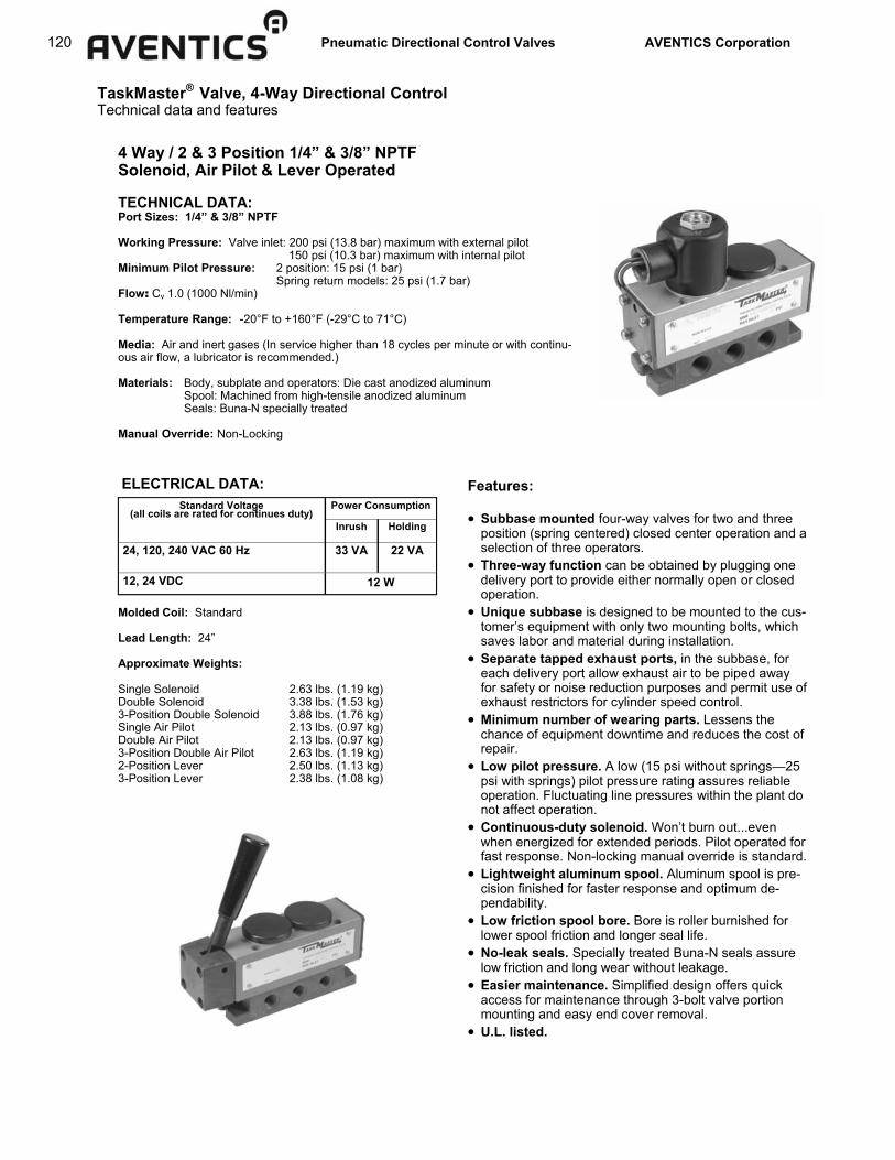
120 Pneumatic Directional Control Valves AVENTICS Corporation
ELECTRICAL DATA: Standard Voltage
(all coils are rated for continues duty) Power Consumption
Inrush Holding
24, 120, 240 VAC 60 Hz 33 VA 22 VA
12, 24 VDC 12 W
4 Way / 2 & 3 Position 1/4” & 3/8” NPTF Solenoid, Air Pilot & Lever Operated TECHNICAL DATA: Port Sizes: 1/4” & 3/8” NPTF Working Pressure: Valve inlet: 200 psi (13.8 bar) maximum with external pilot 150 psi (10.3 bar) maximum with internal pilot Minimum Pilot Pressure: 2 position: 15 psi (1 bar) Spring return models: 25 psi (1.7 bar) Flow: Cv 1.0 (1000 Nl/min) Temperature Range: -20°F to +160°F (-29°C to 71°C) Media: Air and inert gases (In service higher than 18 cycles per minute or with continu-ous air flow, a lubricator is recommended.) Materials: Body, subplate and operators: Die cast anodized aluminum Spool: Machined from high-tensile anodized aluminum Seals: Buna-N specially treated Manual Override: Non-Locking
Molded Coil: Standard Lead Length: 24” Approximate Weights: Single Solenoid 2.63 lbs. (1.19 kg) Double Solenoid 3.38 lbs. (1.53 kg) 3-Position Double Solenoid 3.88 lbs. (1.76 kg) Single Air Pilot 2.13 lbs. (0.97 kg) Double Air Pilot 2.13 lbs. (0.97 kg) 3-Position Double Air Pilot 2.63 lbs. (1.19 kg) 2-Position Lever 2.50 lbs. (1.13 kg) 3-Position Lever 2.38 lbs. (1.08 kg)
Features: • Subbase mounted four-way valves for two and three
position (spring centered) closed center operation and a selection of three operators.
• Three-way function can be obtained by plugging one delivery port to provide either normally open or closed operation.
• Unique subbase is designed to be mounted to the cus-tomer’s equipment with only two mounting bolts, which saves labor and material during installation.
• Separate tapped exhaust ports, in the subbase, for each delivery port allow exhaust air to be piped away for safety or noise reduction purposes and permit use of exhaust restrictors for cylinder speed control.
• Minimum number of wearing parts. Lessens the chance of equipment downtime and reduces the cost of repair.
• Low pilot pressure. A low (15 psi without springs—25 psi with springs) pilot pressure rating assures reliable operation. Fluctuating line pressures within the plant do not affect operation.
• Continuous-duty solenoid. Won’t burn out...even when energized for extended periods. Pilot operated for fast response. Non-locking manual override is standard.
• Lightweight aluminum spool. Aluminum spool is pre-cision finished for faster response and optimum de-pendability.
• Low friction spool bore. Bore is roller burnished for lower spool friction and longer seal life.
• No-leak seals. Specially treated Buna-N seals assure low friction and long wear without leakage.
• Easier maintenance. Simplified design offers quick access for maintenance through 3-bolt valve portion mounting and easy end cover removal.
• U.L. listed.
TaskMaster® Valve, 4-Way Directional Control Technical data and features

Pneumatic Directional Control Valves AVENTICS Corporation 121
Solenoid Operated, 2 Position Subbase Mounted Single or Double Solenoid Operated
Port Size Part No. Model No.
With 1/4” subbase R431008482 PJ-025771-00000
With 3/8” subbase R431008499 PJ-035771-00000
Less subbase R431008466 PJ-015771-00000
Coil Voltages *Last Digit in Model Code
**Primary **Secondary
120VAC, 60 Hz 38VDC 1
240VAC, 60 Hz 70VDC 2
480VAC, 60 Hz 145VDC 3
12VDC 42VAC, 60 Hz 4
24VDC 86VAC, 60Hz 5
3 Position Subbase Mounted Spring-Centered Double Sole-noid
*See valve model codes. (Does not apply to Hopper Dump Valve version P –060681-00001 or explosion proof models.) **Primary and secondary voltages will be stenciled on the solenoid data plate.
Coil Voltages: The coil voltage of a solenoid operator is identified by the last digit of the valve model code. The last digit of all solenoid valve model codes listed iden-tifies a 120VAC, 60 Hz coil. Solenoid valves with other ratings may be ordered by using the table at right and substituting the appropriate digit in the model code (not part number beginning with R). Other Notes: Solenoid pilot pressure must be a minimum of 25 psi with return springs, 15 psi less return springs and a maximum of 150 psi. A flush, non-locking manual override is standard for manual operation when the electric power is off. Other optional fea-tures are available upon request such as high pressure (200 psi) solenoids.
Explosion Proof Valves
Model code (and old part number) shown in parenthesis.
Port Size (120VAC version)
See Coil Voltages Note
Single Solenoid Double Solenoid
Internal External Internal External
With 1/4” subbase R431008475 (PJ-022711-00000)
R431008471 (PJ-021711-00000)
R431008479 (PJ-022771-00000)
R431008474 (PJ-021771-00000)
With 3/8” subbase R431008491 (PJ-032711-00000)
R431008488 (PJ-031711-00000)
R431008495 (PJ-032771-00000)
R431008490 (PJ-031771-00000)
Valve less subbase R431008459 (PJ-012711-00000)
R431008456 (PJ-011711-00000)
R431008462 (PJ-012771-00000)
R431009192 (PJ-011771-00000)
Port Size Part No. Model No.
1/4” - 120VAC, like PJ22711 R431005866 P -061772-00000
1/4” - 120VAC, like PJ12711 R431009194 P -060887-K0000
1/4” - 24VDC, like PJ12715 R431005602 P -060887-00004
TaskMaster® Valve, 4-Way Directional Control Solenoid operated models, 2 & 3 Position, 1/4” & 3/8” NPTF
For 3 position, Spring-centered models only
Solenoid Exhaust
1/2 - 14 NPS Conduit Connection
Manual Override
1/4 - 18 PTF OR
3/8 - 18 PTF 5 Places
External Solenoid Pilot Port (plugged when Internal ported) 1/8 - 27 NPTF

122 Pneumatic Directional Control Valves AVENTICS Corporation
TaskMaster® Valve, 4-Way Directional Control Air pilot and lever operated models
2 Position Subbase Mounted Single or Double Air Pilot Operated
Model code (and old part number) shown in parenthesis.
Port Size Single A.P. Double A.P.
With 1/4” subbase R431008469 (PJ-021610-00000)
R431008470 (PJ-021660-00000)
With 3/8” subbase R431008486 (PJ-031610-00000)
R431008487 (PJ-031660-00000)
Less subbase R431008454 (PJ-011610-00000)
PJ-015771-00000 (PJ-011660-00000)
2 and 3 Position Subbase Mounted Lever Operated
Port Size 2 Pos. with Spring 2 Pos. w/o Spring
With 1/4” subbase R431008468 (PJ-020210-00000)
R431008467 (PJ-020200-00000)
With 3/8” subbase R431008485 (PJ-030210-00000)
R431008484 (PJ-030200-00000)
Less subbase R431009175 (PJ-010210-00000)
R431008453 (PJ-010200-00000)
3 Pos. Spring Ctr.
R431008481 (PJ-023210-00000)
R431008498 (PJ-033210-00000)
R431008465 (PJ-013210-00000)

Pneumatic Directional Control Valves AVENTICS Corporation 123
Note: All subbase ports are 3/8” NPT.
Hopper Dump Valve
Last Digit*
Coil Voltage Part Numbers
Solenoid Operator Kit
Ext. Pilot Internal Pilot
1 120VAC, 60 Hz R431005146 R431005137 R431002779
2 240VAC, 60 Hz R431005149 R431005143 R431002780
3 480VAC, 60 Hz — R431005144 R431002781
4 12VDC R431005147 R431005140 R431002783
5 24VDC R431005148 R431005142 R431002782
Solenoid
Repair Kits, Subplates and Miscellaneous Parts
Part No. Description
R431005395 Valve body kit
R431006634 Valve body kit, Viton
R431005396 Operator kit
R431005397 Operator kit, Viton
R431005645 Solenoid repair kit (includes plunger, spring &
gasket)
R431006057 Solenoid exhaust filter
R431006858 Solenoid sleeve (armature)
Repair Kits/Parts
Subplates
Part No. Description
R431005110 1/4” NPT subplate
R431005109 3/8” NPT subplate
Solenoid Operators and Kits
Coils Last Digit* Part no.
1 R431005915 (P –061920-00000)
2 R431005916 (P –061920-00001)
Coil Voltage
120VAC, 60 Hz
240VAC, 60 Hz 3 R431005917 (P –061920-00002) 480VAC, 60 Hz 4 R431005919 (P –061920-00004) 12VDC 5 R431005918 (P –061920-00003) 24VDC
*Last digit in model code. (Does not apply to Hopper Dump Valve version P –060681-00001 or explosion proof models.)
TaskMaster® Valve, 4-Way Directional Control Hopper dump valve; repair kits, subplates and parts
Part No. R431005556 (old P –060681-00001) Part No. R431005557 (old P –060681-00002)* This unique version is typically used for operating hoppers on many types of trailers hauling different types of aggregate. The valve has solenoid and handle operators. The solenoid permits remote operation of the valve. The handle operates in conjunction with a bleeder button which depressurizes the air spring return allowing the handle to be moved. Manual operation can only be obtained with the solenoid de-energized. *Higher flow due to plugs omitted from EA and EB ports.

124 Pneumatic Directional Control Valves AVENTICS Corporation
PowerMaster® Valve, 4-Way Directional Control Technical data and features
4 Way / 2 & 3 Position 1/4” - 1-1/4” NPTF Solenoid, Air Pilot & Mechanical Operators TECHNICAL DATA: Port Sizes: 1/4”, 3/8”, 1/2”, 3/4”,1” 1-1/4” NPTF Working Pressure: Maximum valve inlet air pressure: 150 psi (10.3 bar) Minimum air pilot pressure: 15 psi (1.0 bar) w/o return spring (all sizes) 30 psi (2.1 bar) 1” and 1-1/4” valves w/return spring 40 psi (2.8 bar) 1/2” and 3/4” valves w/return spring 50 psi (3.4 bar) 1/4” and 3/8” valves w/return spring Valves can also be used for vacuum or dual pressure service when externally piloted. Flow: Cv 2.39 (2390 Nl/min) 1/4” NPTF Cv 3.73 (3730 Nl/min) 3/8” NPTF Cv 6.17 (6170 Nl/min) 1/2” NPTF Cv 7.88 (7880 Nl/min) 3/4” NPTF Cv 13.61 (13,610 Nl/min) 1” NPTF Cv 15.75 (15,750 Nl/min) 1-1/4” NPTF Temperature Range: -20°F to +160°F (-29°C to 71°C) Media: Air and inert gases (In service higher than 18 cycles per minute or with continuous air flow, a lubricator is recommended.) Materials: Bodies and operators: Die cast aluminum Spool: Machined from high-tensile aluminum, hard anodized, ground & polished to 8 micro-inch finish Seals: Buna-N, oil-resistant, and bonded to a metallic ring (Hl-Nitrile Buna-N seals are also available. Manual Override: Non-Locking Electrical Data:
Features: • Response time. Actual test data shows only 175
milliseconds is required to fill a 250 cubic inch volume to 80% of line pressure with a normally closed solenoid operated valve. Where a spring is used to open the valve (normally open valve) only 253 milliseconds is required to fill the same volume.
• Continuous-duty solenoid. Won’t burn out...even when energized for extended periods. Pilot operated for fast response.
• Lightweight aluminum spool of extra large diameter assures high-speed performance. Requires only short movement to deliver high-capacity air flow. File-hard anodized surface, polished to an 8 micro-inch finish, withstands wear and abrasion; offers greatest sealing qualities, minimum friction and maximum speed. Spool is balanced so air pressure won’t affect its position.
• Low-friction, positive sealing ring is actually two seals in one; an outer static seal and an inner dynamic seal bonded to a metallic spacer ring. The ring protects the inner seal from the radical compression absorbed by the other seal. Assures longest life with positive sealing.
• Seal retainers keep inner and outer sealing surfaces in
precise position for maximum reliability and efficiency. Combined with the non-compressible seal rings, PowerMaster valve retainers eliminate tolerance build-up in the free stack height of both retainers and seals.
• Free-floating piston with extra large surface area means faster response at lower pressures.
• Manual non-locking overrides allow supplementary manual control an permits operating the valve when the electric power is off.
• External pilot allows an independent air supply to be connected to the pilot port in the valve operator or subplate for air pilot pressure.
• Wire leads of 24” allows simplified conduit wiring. • Solenoid coil removal. Unscrew hex nut and slip off the
solenoid housing and coil. • Exhaust restrictors can be used in either or both exhaust
port to provide speed control of cylinders. (Refer to Accessory Valve catalog SC-400.)
Standard Voltage (all coils are rated for continues duty)
Power Consumption
Inrush Holding
120, 240 VAC 60 Hz 33 VA 22 VA
12, 24 VDC 12 W

Pneumatic Directional Control Valves AVENTICS Corporation 125
Single & Double Solenoid Coil Voltages 120 VAC part numbers are shown on this page, for other voltages, use the following table and substitute the appropriate suffix on the MODEL number of the valve being used. Single Solenoid
4 Way, Tapped Exhaust
PowerMaster® Valve, 4-Way Directional Control 4 Way, 2 & 3 Position, single and double solenoid operated Tapped body, 1/4” through 3/4” NPTF models
Double Solenoid: 4 Way, Tapped Exhaust
Suffix: Single
Solenoid
Suffix: Double
Solenoid
AC 120 Volts 60 Hz 8500 8484
AC 240 Volts 60 Hz 8700 8686
AC 480 Volts 60 Hz 8900 8888
AC 110 Volts 50 Hz 8100 8080
AC 220 Volts 50 Hz 8300 8282
DC 12 Volts 9500 9494
DC 24 Volts 9100 9090
DC 240 Volts 9300 9292
Coil Voltages
Port Size
Internal Air Pilot External Air Pilot
Center Spring, 3 Pos. Closed Ctr.
2 Position No Springs
Center Spring, 3 Pos. Closed Ctr.
2 Position No Springs
1/4” R431008524 (PT-024117-08484)
R431008521 (PT-024107-08484)
— (PT-024115-08484)
R431009183 (PT-024105-08484)
3/8” R431008550 (PT-034117-08484)
R431008545 (PT-034107-08484)
R431008549 (PT-034115-08484)
R431008541 (PT-034105-08484)
1/2” R431008575 (PT-044117-08484)
R431008571 (PT-044107-08484)
R431008574 (PT-044115-08484)
R431009193 (PT-044105-08484)
3/4” R431008601 (PT-064117-08484)
R431008598 (PT-064107-08484)
R431008600 (PT-064115-08484)
R431008593 (PT-064105-08484)
Internal Air Pilot External Air Pilot
Part No. Model No. Part No. Model No.
1/4” R431008519 PT-024106-08500 R431008516 PT-024104-08500
3/8” R431008542 PT-034106-08500 R431008538 PT-034104-08500
1/2” R431008566 PT-044106-08500 R431008564 PT-044104-08500
3/4” R431008595 PT-064106-08500 R431008589 PT-064104-08500
Port Size
B C D E F G H I J IN mm IN mm IN mm IN mm IN mm IN mm IN mm IN mm IN mm
SINGLE 1/4” & 3/8” 1.50 38 2.56 65 2.44 62 6.65 169 1.00 25 2.00 51 .69 18 1.69 43 .28 7 SOLENOID 1/2” & 3/4” 1.88 48 3.06 78 2.94 75 8.03 204 1.19 30 2.38 60 .94 24 2.00 56 .28 7 DOUBLE 1/4” & 3/8” 1.50 38 2.56 65 2.56 65 6.91 176 1.00 25 2.00 51 .69 18 1.81 46 .28 7
SOLENOID 1/2” & 3/4” 1.88 48 3.06 78 3.06 78 8.28 210 1.19 30 2.38 60 .94 24 2.12 54 .28 7
A
L M N O P Q R S T IN mm IN mm IN mm IN mm IN mm IN mm IN mm IN mm IN mm IN mm
SINGLE .50 13 1.12 28 1.06 27 1.56 40 1.94 49 3.31 84 4.38 111 1.56 40 1.50 38 3.00 76 SOLENOID .50 13 1.44 37 1.06 27 1.69 43 2.06 52 3.44 87 4.50 114 1.56 40 1.75 44 3.50 89 DOUBLE .50 13 1.12 28 1.06 27 1.56 40 5.25 133 3.31 84 4.38 111 1.56 40 1.50 38 3.00 76
SOLENOID .50 13 1.44 37 1.06 27 1.69 43 6.62 168 3.44 87 4.50 114 1.56 40 1.75 44 3.50 89
K
For part number, contact factory.

126 Pneumatic Directional Control Valves AVENTICS Corporation
Single Solenoid, Tapped Exhaust Port Size
Part No. Model No.
1” R431008610 PT-084106-03100
1-1/4” R431008619 PT-094106-03100
Approx. Weight lbs. (kg)
10 (4.5)
10 (4.5)
Note: All valves on this page are also available in 24VDC. Substitute –04300 as the suffix in the model code for single solenoid models, or –04242 for double solenoid valves. 120VAC and 24VDC are the only voltages available in 1” and 1- 1/4” models. A com-plete listing of model codes to new part numbers is available online on the Power-Master Valve page at: www.aventics.com/us/pmvalve
Dimensions in inches (mm)
A B C D E F G H
1”-11 1/2 1 1/4”-11 1/2
13.44 (341)
4.13 (105)
2.59 (66)
4.38 (111)
4.19 (106)
4.00 (102)
1.31 (33)
J K L M N O P Q R S T
2.69 (68)
2.63 (67)
2.75 (70)
2.13 (54)
1.31 (33)
1.50 (38)
0.34 (8.7)
0.63 (15.9)
3.00 (76)
2.06 (52)
2.19 (56)
Double Solenoid, Tapped Exhaust Port Size
Internal Air Pilot Approx. Weight lbs. (kg)
Center Spring, 3 Pos. Closed Ctr.
Center Spring, 3 Pos. Exhaust Open Ctr. No Springs
1” R431008613 PT-084117-03030
R431008615 PT-084517-03030
R431008611 PT-084107-03030 12.25 (5.57)
1-1/4””
R431008623 PT-094117-03030
R431008625 PT-094517-03030
R431008621 PT-094107-03030 12.25 (5.57)
A B C
1”-11 1/2 1 1/4”-11 1/2
16.25 (413)
4.13 (105)
2.13 (54)
1.31 (33)
1.50 (38)
D
2.59 (66)
0.34 (8.7)
E
4.38 (111)
0.63 (15.9)
F
4.19 (106)
4.06 (103)
G
2.75 (75)
2.63 (67)
H
1.31 (33)
2.19 (56)
J
2.88 (68)
2.06 (52)
M N O P Q R S T U
K
2.63 (67)
V
3.00 (76)
L
2.88 (73)
Dimensions in inches (mm)
PowerMaster® Valve, 4-Way Directional Control 4 Way, 2 & 3 Position, single and double solenoid operated Tapped body, 1” through 1-1/4” NPTF models

Pneumatic Directional Control Valves AVENTICS Corporation 127
4 Way, Tapped Exhaust, Lever Operated Port Size
Two Position
Return Spring Detents No Spring or Detents
1/4” R431008510 (PT-024101-00200)
R431008508 (PT-024101-00114)
R431008507 (PT-024101-00100) 3.25 (1.48)
3/8” R431008532 (PT-034101-00200)
R431008530 (PT-034101-00114)
R431008529 (PT-034101-00100) 3.25 (1.48)
1/2” R431008558 (PT-044101-00200)
R431008556 (PT-044101-00114)
R431008555 (PT-044101-00100) 4.25 (1.93)
3/4” R431008583 (PT-064101-00200)
R431008581 (PT-064101-00114)
R431008580 (PT-064101-00100) 4.25 (1.93)
Approx. Weight lbs. (kg)
Port Size
Three Position Approx. Weight lbs. (kg)
Closed Center
Center Springs Detents Center Springs Detents
1/4” R431008511 (PT-024101-00300)
R431008509 (PT-024101-00115)
R431008526 (PT-024501-00300)
R431008525 (PT-024501-00115) 3.25 (1.48)
3/8” R431008533 (PT-034101-00300)
R431008531 (PT-034101-00115)
R431008553 (PT-034501-00300)
R431008552 (PT-034501-00115) 3.25 (1.48)
1/2” R431008559 (PT-044101-00300)
R431008557 (PT-044101-00115)
R431008577 (PT-044501-00300)
R431008576 (PT-044501-00115) 4.25 (1.93)
3/4” R431008584 (PT-064101-00300)
R431008582 (PT-064101-00115)
R431008604 (PT-064501-00300)
R431008603 (PT-064501-00115) 4.25 (1.93)
Exhaust Open Center
A B C 1/4-18 3/8-18
8.13 (207)
7.25 (184)
1.50 (38)
1.06 (27)
0.88 (22.2)
D 3.00 (76)
1.56 (40)
E 1.50 (38)
37°
F 2.44 (62)
5.19 (132)
G 0.69
(17.5)
2.00 (51)
H 1.00 (25)
1.38 (35)
J 1.13 (29)
2.75 (70)
M N O P Q R S T U
K 0.44
(11.2)
V 1.94 (49)
L 1.69 (43)
1/2-14 3/4-14
9.44 (240)
8.69 (221)
3.50 (89)
1.75 (44)
2.94 (75)
0.94 (23.9)
1.19 (30)
1.34 (34)
0.63 (16.0)
2.00 (51)
1.88 (48)
1.06 (27)
1.09 (43)
1.69 (43) 35° 5.44
(138) 2.38 (60)
1.63 (41)
3.25 (83)
2.06 (52)
Dimensions in inches (mm)
PowerMaster® Valve, 4-Way Directional Control 4 Way, 2 & 3 Position, lever operated Tapped body, 1/4” through 3/4” NPTF models

128 Pneumatic Directional Control Valves AVENTICS Corporation
4 Way, Tapped Exhaust, Treadle Operated Port Size
Approx. Weight lbs. (kg) Less Springs Center Springs
Closed Center
1/4” R431008513 (PT-024101-01100)
R431008514 (PT-024101-01200) 4.25 (1.93)
3/8” R431008535 (PT-034101-01100)
R431008536 (PT-034101-01200) 4.25 (1.93)
1/2” R431008561 (PT-044101-01100)
R431008562 (PT-044101-01200) 5.50 (2.49)
3/4” R431008586 (PT-064101-01100)
R431008587 (PT-064101-01200) 5.50 (2.49)
A B C D E F G H J K 1/4-18 3/8-18
1.06 (27)
1.56 (40)
3.31 (84)
5.31 (135)
10.44 (265)
1.50 (38)
0.69 (17.5)
1.69 (43)
3.00 (76)
1/2-14 3/4-14
1.06 (27)
1.69 (43)
3.88 (99)
5.75 (146)
11.94 (303)
1.88 (48)
0.94 (23.9)
2.00 (51)
3.50 (89)
L M N O P Q R S T U 2.00 (51)
1.00 (25)
2.44 (62)
3.56 (90)
1.78 (45)
1.50(38)
2.75 (70)
1.38 (35)
1.94 (49)
7.25 (184)
3.38 (86)
1.19 (30)
2.94 (75)
3.56 (90)
1.78 (45)
1.75 (44)
3.25 (83)
1.63 (41)
2.06 (52)
8.69 (221)
Dimensions in inches (mm)
Treadle Operators Treadle operators are furnished without a return spring for two-position heel and toe operation. For three-position operation, centering springs are used. The two-position model may also be used as a three-position, closed center combination.
PowerMaster® Valve, 4-Way Directional Control 4 Way, 2 & 3 Position, treadle operated Tapped body, 1/4” through 3/4” NPTF models
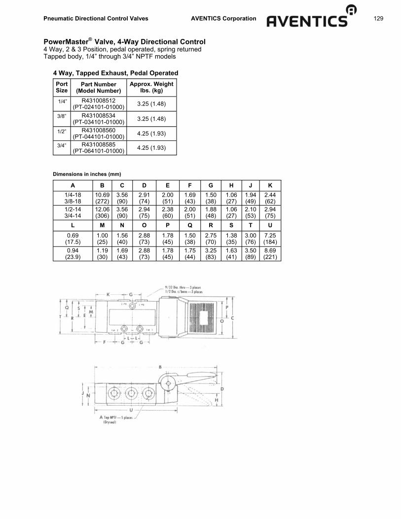
Pneumatic Directional Control Valves AVENTICS Corporation 129
4 Way, Tapped Exhaust, Pedal Operated Port Size
Part Number (Model Number)
Approx. Weight lbs. (kg)
1/4” R431008512 (PT-024101-01000) 3.25 (1.48)
3/8” R431008534 (PT-034101-01000) 3.25 (1.48)
1/2” R431008560 (PT-044101-01000) 4.25 (1.93)
3/4” R431008585 (PT-064101-01000) 4.25 (1.93)
A B C D E F G H J K 1/4-18 3/8-18
10.69 (272)
3.56 (90)
2.91 (74)
2.00 (51)
1.69 (43)
1.50 (38)
1.06 (27)
1.94 (49)
2.44 (62)
1/2-14 3/4-14
12.06 (306)
3.56 (90)
2.94 (75)
2.38 (60)
2.00 (51)
1.88 (48)
1.06 (27)
2.10 (53)
2.94 (75)
L M N O P Q R S T U 0.69
(17.5) 1.00 (25)
1.56 (40)
2.88 (73)
1.78 (45)
1.50(38)
2.75 (70)
1.38 (35)
3.00 (76)
7.25 (184)
0.94 (23.9)
1.19 (30)
1.69 (43)
2.88 (73)
1.78 (45)
1.75 (44)
3.25 (83)
1.63 (41)
3.50 (89)
8.69 (221)
Dimensions in inches (mm)
PowerMaster® Valve, 4-Way Directional Control 4 Way, 2 & 3 Position, pedal operated, spring returned Tapped body, 1/4” through 3/4” NPTF models

130 Pneumatic Directional Control Valves AVENTICS Corporation
4 Way, Tapped Exhaust, Air Pilot Operated
A B C D E F G H J K 1/4-18 3/8-18
6.63 (168)
3.00 (76)
1.50 (38)
1.00 (25)
2.56 (65)
0.69 (17.5)
1.88 (48)
0.69 (17.5)
1.13 (29)
1/2-14 3/4-14
8.00 (203)
3.50 (89)
1.75 (44)
1.19 (30)
3.06 (78)
0.94 (23.9)
2.38 (60)
0.69 (17.5)
1.44 (37)
L M N O P Q R S T 1.50 (38)
1.94 (49)
1.06 (27)
1.56 (40)
0.28 (7.1)
0.50 (12.7)
2.00 (51)
1.38 (35)
2.75 (70)
1.88 (48)
2.06 (52)
1.06 (27)
1.69 (43)
0.28 (7.1)
0.50 (12.7)
2.38 (60)
1.63 (41)
3.25 (83)
1-11 1/2 1 1/4—11 1/2
10.63 (270)
4.38 (111)
5.19 (132)
1.50 (38)
4.00 (102)
1.31 (33)
3.25 (83)
0.75 (19.1)
1.94 (49)
2.63 (67)
2.59 (66)
1.31 (33)
2.13 (54)
0.34 (8.6)
0.63 (15.9)
3.00 (76)
2.06 (52)
4.13 (105)
Dimensions in inches (mm)
Port Size
Double Air Pilot Approx. Weight lbs. (kg)
Center Springs, Closed Center
Center Springs, Exh. Open Center No Springs
1/4” R431008515 (PT-024104-01700)
R431008523 (PT-024115-01616)
R431008528 (PT-024515-01616)
R431008518 (PT-024105-01616) 2.75 (1.25)
3/8” R431008537 (PT-034104-01700)
R431008547 (PT-034115-01616)
R431008554 (PT-034515-01616)
R431008540 (PT-034105-01616) 2.75 (1.25)
1/2” R431008563 (PT-044104-01700)
R431008573 (PT-034115-01616)
R431008578 (PT-044515-01616)
R431008565 (PT-044105-01616) 4.25 (1.93)
3/4” R431008588 (PT-064104-01700)
R431008599 (PT-064115-01616)
R431008606 (PT-064515-01616)
R431008592 (PT-064105-01616) 4.25 (1.93)
Single Air Pilot
1” R431008607 (PT-084104-01700)
R431008612 (PT-084115-01616)
R431008614 (PT-084515-01616)
R431008609 (PT-084105-01616) 7.75 (3.52)
1-1/4”
R431008616 (PT-094104-01700)
R431008622 (PT-094115-01616)
R431008624 (PT-094515-01616)
R431008618 (PT-094105-01616) 7.75 (3.52)
PowerMaster® Valve, 4-Way Directional Control 4 Way, 2 & 3 Position, air pilot operated Tapped body, 1/4” through 1-1/4” NPTF models

Pneumatic Directional Control Valves AVENTICS Corporation 131
* These seals have been tested and have proven compatible with ASTM #1 and #3 oils as well as ANDEROL 500.
Repair Kits (Buna-N elastomers)
* Two each required for double operator valves.
With these repair kits, the elastomer seals and some common wear parts on the component are renewed. On se-verely worn or damaged components, additional parts may be required. For additional parts, information and service instructions, refer to Service Manual SM-300.8000.
Port Size Old Part No. Repair Kit Part No.
1/4” - 3/8” Valve spool kit R431004790 P -058875-00000
1/2” - 3/4” Valve spool kit R431004795 P -058884-00000
1” - 1 1/4” Valve spool kit R431004793 P -058880-00000
1/4” - 3/8” *Solenoid Repair R431006971 P -066948-00000
1/2” - 3/4” *Solenoid Repair R431006972 P -066948-00001
1” - 1 1/4” *Solenoid Repair R431004792 P -058878-00000
1/4” - 3/8” *Air Pilot Operator R431005569 P -060693-00000
1/2” - 3/4” *Air Pilot Operator R431005568 P -060692-00000
1” - 1 1/4” *Air Pilot Operator R431005567 P -060691-00000
Repair Kits (Hi-Nitrile)** Port Size Repair Kit Part No. Old Part No.
1/4” - 3/8” Valve spool kit R431004791 P -058875-00001
1/2” - 3/4” Valve spool kit R431004796 P -058884-00001
1” - 1 1/4” Valve spool kit R431004794 P -058880-00001
Voltage Coil Only Complete Solenoid Operator
120VAC, 60 Hz R431005915 R431002779
240VAC, 60 Hz R431005916 R431002780
480VAC, 60 Hz R431005917 R431002781
12VDC R431005918 R431002782
24VDC R431005919 R431002783
240VDC R431005920 R431002789
120VAC, 50 Hz — R431005751
240VAC, 50 Hz — R431005750
Sol. Operator Repair Kit ** R431005645
Solenoid Exhaust Muffler R431006057
Solenoid Repair for 1/4” – 3/4” Valves
Voltage Coil Only
120VAC, 60 Hz R431004228
240VAC, 60 Hz R431004229
480VAC, 60 Hz R431009174
12VDC R431004223
24VDC R431004222
230VDC R431004224
120VAC, 50 Hz R431004225
240VAC, 50 Hz —
Sol. Operator Repair Kit*** Part No.
External Pilot R431004647
Internal Pilot R431004652
Solenoid Repair for 1” – 1 1/4” Valves
*** Coils are not included and must be ordered separately.
** Includes plunger, return spring and gasket. Order coil separately.
PowerMaster® Valve, 4-Way Directional Control Repair kits

132 Pneumatic Directional Control Valves AVENTICS Corporation
Technical Section Valve diagrams
AVENTICS CERAM™ 4 WAY DIRECTIONAL CONTROL VALVE-SLIDE TYPE
Air Pilot 2 Position Metal Spring Return
12 End for Air Spring Return
12 End for Double Air Pilot
Air Pilot 3 Position Exhaust Open Center
Air Pilot 3 Position Closed Center
Single Solenoid 2 Position Metal Spring Return
Single Solenoid 2 Position Air Spring Return
Double Solenoid 2 Position
Double Solenoid 3 Position Exhaust Open Center
Double Solenoid 3 Position Closed Center
Port Marking 1=
2 & 4= 3 & 5=
12 & 14=
Supply Pressure Delivery (Cylinder) Ports Exhaust Ports External Pilot Ports

Pneumatic Directional Control Valves AVENTICS Corporation 133
Technical Section Valve diagrams
Miniblock 3-Way Valve
2mm Miniblock™ Roller Cam Operated
Series 840 4-Way Valve
Single Solenoid Air Spring Return
Port Marking P= A= R=
Supply Pressure Delivery (Cylinder) Ports Exhaust Ports
Port Marking 1(P)=
2(B) & 4(A)= 3(R)=
Supply Pressure Delivery (Cylinder) Ports Exhaust Ports
Series 740 4-Way Directional Control Valves - Diaphragm/Poppet Type
Port Marking 1=
2(B) & 4(A)= 3(S) & 5(R)=
12(Y) & 14(Z)=
Supply Pressure Delivery (Cylinder) Ports Exhaust Ports Air Pilot Ports
Single Solenoid Air Spring Return
Double Solenoid 2 Position
Single Air Pilot Air Spring Return
Double Air Pilot 2 Position

134 Pneumatic Directional Control Valves AVENTICS Corporation
Technical Section Valve diagrams
Series CD07 4-Way Directional Control Valves - Spool Type
Mechanically Operated Single Air Pilot Double Air Pilot 2 Position
Double Air Pilot 2 Position Closed Center
Single Solenoid Operated Double Solenoid 2 Position
Double Solenoid 3 Position Exhaust Open Center
Port Marking 1=
2 & 4= 3 & 5=
12 & 14=
Supply Pressure Delivery (Cylinder) Ports Exhaust Ports External Pilot Ports

Pneumatic Directional Control Valves AVENTICS Corporation 135
Technical Section Application sketches
AVENTICS DIRECTIONAL CONTROL VALVE APPLICATION - to move cylinders & actuators.
Single acting cylinders need a 3/2 valve, meaning 3 ports and 2 positions. Port 1 = supply pressure; 2 = out to cylinder; 3 = exhaust from cylinder. (Unused port of a 4/2 or 5/2 valve can be plugged to provide a 3/2 function.)
Double acting cylinders need a 4/2 or 5/2 valve (4 or 5 ports, 2 positions).
Connect a single acting cylinder to a 3/2 valve (simple cir-cuit).
Connecting a double acting cylinder to a 5/2 valve.
Connecting meter-out flow controls for speed control in both directions.
Rodless cylinders: regulated in same way as conven-tional cylinders (shown here with 5/2 valve with built-in flow control).
For vertical applications it is possible to use an extra pressure regulator for mass equilibrium and chick-choke valves for speed control.
Dual pressure piping with a lower pressure returning a piston rod with no load can reduce energy costs up to 30%
Pneumatic rectifier circuit allows unidirectional air motor to operate at two different, adjustable speeds, with brak-ing action, using only one closed center valve.

136 Pneumatic Directional Control Valves AVENTICS Corporation
Technical Section Vacuum Applications
#1 VACUUM-PRESSURE APPLICATION Vacuum-Pick up object (Non-energized) Pressure-Blow off object (Energized) (Switching Ports 2 & 4, 3 & 5 will reverse the above action) 3 Way Application-Internal pilot supply Port use: 1. Supple Pressure 2. Plugged 3. Not Used 4. To Vacuum Cup 5. From Vacuum Source
#3 VACUUM-GRAVITY APPLICATION Vacuum-Pick up object (Energized) Atmosphere-Gravity drop object (Non-energized) (Switching Ports 2 & 4 will reverse the above action) 3 Way Application-External Pilot Supply required Port use: 1. Vacuum source 2. Plugged 3. Not Used 4. To Vacuum Cup 5. Atmosphere
#2 VACUUM-PRESSURE APPLICATION Vacuum-Pick up object Pressure-Blow off object 4 Way Application-Internal Supply Conditions Non-Energized-Blow off Port 2, Pick up Port 4 Energized-Blow off Port 4, Pick up Port 2 Port use: 1. Supply pressure 2. To vacuum cap 1 3. & 5. To vacuum source 4. To vacuum cup 2
#4 VACUUM-GRAVITY APPLICATION Vacuum-Pick up object Atmosphere-Gravity drop object 4 Way Application-External Pilot Supply required Conditions: Non-energized-Pick ip cup 1, Drop cup 2 Energized-Pick up cup 2, Drop cup 1 Port use: 1. From vacuum source 2. To Vacuum Cup 1 3. & 5. Atmosphere (exhaust) 4. To Vacuum Cup 2
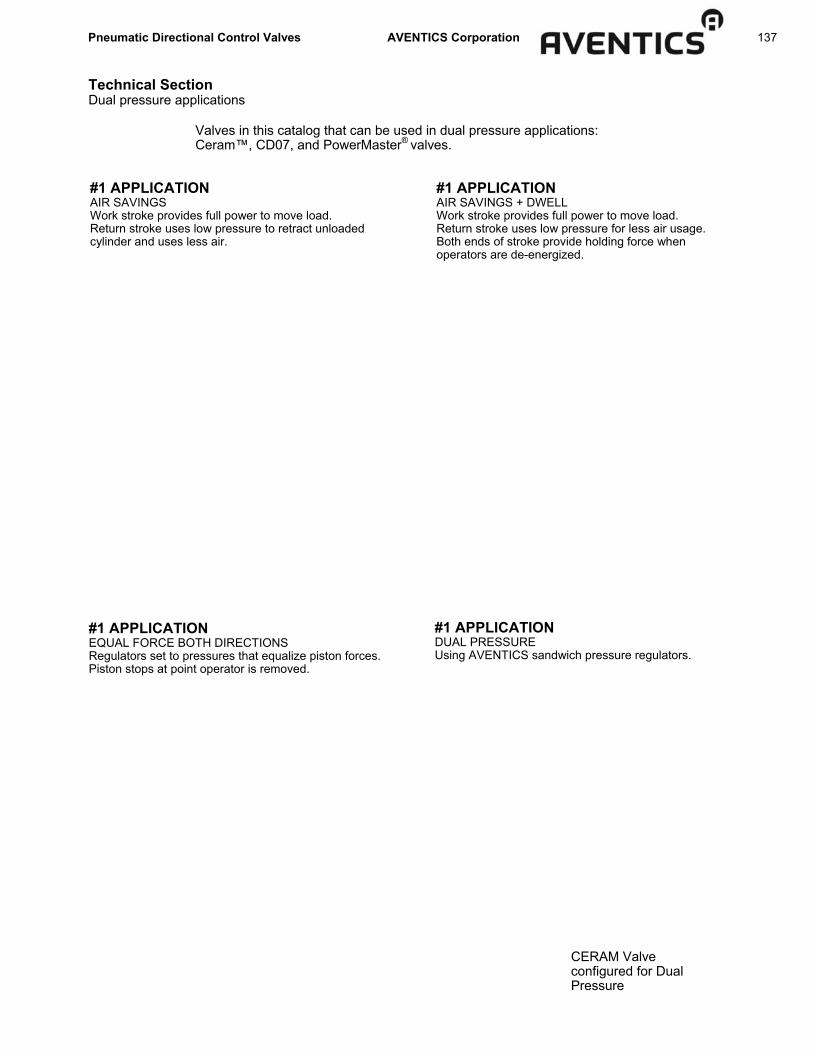
Pneumatic Directional Control Valves AVENTICS Corporation 137
#1 APPLICATION AIR SAVINGS Work stroke provides full power to move load. Return stroke uses low pressure to retract unloaded cylinder and uses less air.
#1 APPLICATION AIR SAVINGS + DWELL Work stroke provides full power to move load. Return stroke uses low pressure for less air usage. Both ends of stroke provide holding force when operators are de-energized.
#1 APPLICATION EQUAL FORCE BOTH DIRECTIONS Regulators set to pressures that equalize piston forces. Piston stops at point operator is removed.
#1 APPLICATION DUAL PRESSURE Using AVENTICS sandwich pressure regulators.
Technical Section Dual pressure applications
Valves in this catalog that can be used in dual pressure applications: Ceram™, CD07, and PowerMaster® valves.
CERAM Valve configured for Dual Pressure

138 Pneumatic Directional Control Valves AVENTICS Corporation
Technical Section Air valve sizing
AIR VALVE SIZING (Note: for cylinder sizing information see catalog SC-200)
FOREWORD The purpose of this section is to provide a convenient method for estimating the port sizes of air valves to be used in general industrial applications. Cylinder bore size, cylinder speeds, operating pressure and the pressure drop through the components are considered in the selection process. Some general guidelines are offered for line lengths and piping. This section is not intended to be an engineering paper on the subject of air flow in pneumatic components. For very critical applications, the user should refer to the more extensive technical literature on the subject. GENERAL INSTRUCTIONS The air valve selected must be capable of delivering the necessary flow of air at an acceptable pressure drop through the valve, lines, and fittings to the power device...most typically a double acting cylinder. For general applications, a pressure drop of 10 to 15 psi through the valve is usually satisfactory. Since pressure drops in a system are additive when components are piped in series, a lower pressure drop such as 5 psi should be used in complex circuits. The Cv charts in this section list actual air flow at the commonly used pressure drops. For other applications, an even lower pressure drop may be indicated. Consult AVENTICS for assistance on critical applications. The Cv value of a component is used to designate the actual flow capacity of that device. The actual flow at various pressure drops, operating pressures and temperature can be mathematically calculated form the Cv value. By definition, a flow path with a Cv value of 1.0 will pass 1 gpm of water with a 1 psi pressure drop under certain standard conditions. The Cv value can also be used to calculate the flow of a compressible fluid such as air, and these methods are widely used in both hydraulics and pneumatics. It is very popular to sized an air valve by matching the NPT port size of the cylinder being used. This usually results in a satisfactory application. The port size on cylinders have been developed over many years of experience. In most cases, the NPT cylinder port has a higher Cv value than the typical valve of the same pipe size. SIZING AIR VALVES WITH THE USE OF FLOW CHARTS The following procedure can be used to size an air valve when the cylinder speed or other conditions do not meet the parameters previously stated. Matching the proper valve with a standard cylinder is very simple by using the following A & B Charts. 1. CHOOSE SYSTEM SUPPLY PRESSURE Choose proper set of A & B Charts by matching system supply pressure (located on upper right corner of following pages). For air motors, spray guns or other continuous flow devices, use the SCFM (Standard Cubic Feet per Minute) listed by the component manufacturers. 2. DETERMINE AIR FLOW REQUIREMENT IN SCFM Find SCFM required in Chart A by matching cylinder bore and cylinder speed (Vips—inches per second) required. Use the extending or retracting stroke speed, whichever is fastest. If the cylinder has a large oversize piston rod, refer to the section titled “Additional Sizing Considerations.”
Vips = S or S T 30/CPM where: Vips = velocity (inches per second) S = stroke (inches) T = time to complete on stroke (seconds) CPM = cycles per minute (a complete cycle consists of one extension and one retraction) 3. DETERMINE THE Cv VALUE REQUIRED Use Chart B to match SCFM (calculated in step 2 above) with acceptable pressure drop columns of r5-r25 psi. For most general applications, a pressure drop of r10 is acceptable. If application speed is critical, r5 psi should be considered. If speed is not critical, r15-r25 psi will choose the most economical (smaller Cv) value. 4. SELECT THE AIR VALVE SIZE Select an air valve with a Cv value equal to or larger than that determined in the previous step. EXAMPLES: 1. What Cv is required for a 2 1/2” bore x 20” stroke cylinder that
must extend completely in 2 seconds? Assume a supply pressure of 60 psi and a pressure drop across the valve of 5 psi.
-Go to the 60 psi supply chart. -Determine the velocity (Vips = S/T) required by dividing stroke (in inches) by extension time: 20”/2 seconds = 10 inches/second -On Chart A, find where the 10 inches per second column intersects the 2 1/2” bore row. SCFM required is 8.7 SCFM. On Chart B, under the pressure drop column of 5 psi, choose a valve that can deliver at least 8.7 SCFM. This indicates that a TaskMaster®, CD07, Size 1 Ceram™, etc. (or any other valve which can deliver at least 8.7 SCFM) has a capacity large enough for this application. 2. What Cv is required for a 6” bore x 30” stroke cylinder
operating at 10 cycles per minute? Assume a supply pressure of 80 psi and a pressure drop of 10 psi.
-Go to the 80 psi supply chart. -Because cycles per minute is a known factor, the velocity must be determined by using the following formula: Vips = S 30/cpm 30” = 30/3 = 10 inches/second (30/10cpm) -On chart A, find where the 10 inches per second column intersects the 6” bore row. SCFM required is 63.2 SCFM. On Chart B, under the pressure drop column of 10 psi, choose a valve that can deliver at least 63.2 SCFM. This indicates that a 1/4” PowerMaster®, Size II Ceram, 3/8” PowerMaster, Size III Ceram, etc. (or any other valve which can deliver at least 63.2 SCFM) has a capacity large enough for this application. Note: If the Vips is not located on Chart A, add 2 or more values to determine required Vips. In example 2, assume that 45 cpm is required. Vips = S = 45 ips. 30/45cpm Add the 25 ips column (158.1 SCFM) and the 20 ips column (126.5 SCFM) for a total of 284.6 SCFM for 45 cpm.
Please Note: As an alternative to these procedures, an online air valve sizing tool is available at www.aventics.com/us
Pneumatic Directional Control Valves AVENTICS Corporation 139
P1 + Pa P2 + Pa
Vp = S T x 12
( ) Supply Pressure + 14.7 14.7
Cv = Q 22.48
T1xG ∆P x (P2+Pa)
Technical Section Air valve sizing
AIR VALVE SIZING (continued)
CYLINDERS If the cylinder has an oversize piston rod and the retracting stroke is fastest and is being used to size the air valve, the volume represented by the rod may be subtracted from the SCFM requirement (common rod diameters are shown in the charts). The speed of the cylinder in inches per second (ips) is the stroke divided by the time in seconds required to complete that stroke. LINES AND LINE LENGTHS If the line lengths between the delivery ports of the air valve and the cylinder ports significantly exceed 10ft. in length, it may be necessary to add the line volume to the SCFM requirement. ADD additional SCFM if the line volume exceeds 20% of the cylinder volume (this occurs often on small cylinders). SCFM=Line Volume (cu. in.) x 60 x RESPONSE TIME CONSIDERATION If the system speed is critical and the cycles per minute required is high, the response time of the valve should be considered. Consult the factory to determine corrected cycles per minute for the individual valve performance in question. In most applications, this is not necessary. VALVE FITTING RESTRICTIONS If tubing is used instead of standard pipe, the valve fitting can sometimes restrict the flow of the valve and the rest of the system. This is normally not a problem, but if the system speed is considered critical, this should be considered. This restriction can be approximated by applying the following equation to the minimum inside diameter of the fitting (I.D.): Corrected Cv = 18 x (I.D.)2
Example: A 3/8” Powermaster™ valve has a Cv of 3.73. A 1/2” tubing fitting is installed in the port that has a minimum inside diameter of .38”. The valve is therefore estimated to have a corrected Cv of 18 x (.38” x .38”) = 2.60 OTHER CONDITIONS The air temperature has some effect on the SCFM requirements and flow capacities. The charts are calculated at 70°F standard temperature. Unless very extreme temperature are present, the margin of error is within the limits of these sizing methods. High humidity tends to decrease the flow capacities of valves. This can be allowed for the Cv selection. MULTIPLE VALVE PATHS & COMPLEX SYSTEMS COMPONENTS IN A SERIES - In a pneumatic circuit where air passes through more than one device in series, the pressure drops are additive (including line pressure losses). In general industrial applications involving cylinders, this occurs most often when the cylinder(s) is speed controlled with the use of flow control check and choke valves. The Cv value of the flow control valve in the free flow direction must be considered. PRESSURE REGULATORS - The capacity of a pressure regulating valve is determined by the drop from set pressure on the delivery side of the regulator. Be sure to check the capacity of a pressure regulator in the manufacturer’s catalog. It is common for a regulator to be one or more pipe sizes larger than the directional valve it is supplying. The regulator should deliver the desired flow with a drop from set pressure that does not affect the performance of the system (usually less than 10%). This is a very common error in general industrial applications.
There are several Cv formulas in use today. The National Fluid Power Association is currently using the following Cv formula (Table A & B as well as all stated AVENTICS Pneumatics Cv values are calculated with this same formula): CAPACITY COEFFICIENT FORMULA Where Cv = capacity coefficient (a numeral) Q = flow in standard cubic feet per minute (SCFM) G = specific gravity of the flowing medium (G = 1 for air) T1 = absolute temperature (degrees F + 460) P1 = inlet pressure (psig) P2 = outlet pressure (psig) (P2 = P1 - ∆P) ∆P = pressure drop (psi) static to static pressure Pa = atmospheric pressure (normally 14.7 psi) NOTE: This equation is valid for Subsonic flow only. To insure subsonic flow (velocities below the speed of sound: 11fps), limit pressure drop so that is between 0.85 and 1.0
PNEUMATIC CYLINDER SPEED where Vp = Cylinder speed (fps) S = Stroke (inches) T = Time to complete above stroke (seconds) PNEUMATIC FLOW REQUIRED (Average) “Q” SCFM avg = C x Dp x S x SPM where SCFM avg = Avg ft3 free air per minute required Dp = Displacement of cylinder in ft3 per inc of stroke S = Stroke in inches SPM = Strokes per minute, count both in and out strokes C = Compression ratio:
Supply pressure (psig) + 14.7 psi 14.7 psi

140 Pneumatic Directional Control Valves AVENTICS Corporation
Technical Section Air valve sizing
BOR
E SC
FM
SCFM
SC
FM
SCFM
SC
FM
SCFM
SC
FM
SCFM
SC
FM
SCFM
SC
FM
SCFM
SC
FM
SCFM
SC
FM
0.62
5 0.
0 0.
1 0.
1 0.
2 0.
2 0.
3 0.
3 0.
4 0.
5 0.
8 1.
1 1.
4 1.
6 1.
9 2.
2 0.
750
0.0
0.1
0.2
0.2
0.3
0.4
0.5
0.6
0.8
1.2
1.6
1.9
2.3
2.7
3.1
1.00
0 0.
1 0.
1 0.
3 0.
4 0.
6 0.
7 0.
8 1.
1 1.
4 2.
1 2.
8 3.
5 4.
2 4.
9 5.
5 1.
125
0.1
0.2
0.4
0.5
0.7
0.9
1.1
1.4
1.8
2.6
3.5
4.4
5.3
6.1
7.0
1.37
5 0.
1 0.
3 0.
5 0.
8 1.
0 1.
3 1.
6 2.
1 2.
6 3.
9 5.
2 6.
6 7.
9 9.
2 10
.5
1.50
0 0.
2 0.
3 0.
6 0.
9 1.
2 1.
6 1.
9 2.
5 3.
1 4.
7 6.
2 7.
8 9.
4 10
.9
12.5
1.
750
0.2
0.4
0.8
1.3
1.7
2.1
2.5
3.4
4.2
6.4
8.5
10.6
12
.7
14.9
17
.0
2.00
0 0.
3 0.
6 1.
1 1.
7 2.
2 2.
8 3.
3 4.
4 5.
5 8.
3 11
.1
13.9
16
.6
19.4
22
.2
2.50
0 0.
4 0.
9 1.
7 2.
6 3.
5 4.
3 5.
2 6.
9 8.
7 13
.0
17.3
21
.7
26.0
30
.3
34.6
3.
000
0.6
1.2
2.5
3.7
5.0
6.2
7.5
10.0
12
.5
18.7
24
.9
31.2
37
.4
43.7
49
.9
3.25
0 0.
7 1.
5 2.
9 4.
4 5.
9 7.
3 8.
8 11
.7
14.6
22
.0
29.3
36
.6
43.9
51
.2
58.6
4.
000
1.1
2.2
4.4
6.7
8.9
11.1
13
.3
17.7
22
.2
33.3
44
.3
55.4
66
.5
77.6
88
.7
5.00
0 1.
7 3.
5 6.
9 10
.4
13.9
17
.3
20.8
27
.7
34.6
52
.0
69.3
86
.6
103.
9 12
1.3
138.
6 6.
000
2.5
5.0
10.0
15
.0
20.0
24
.9
29.9
39
.9
49.9
74
.8
99.8
12
4.7
149.
7 17
4.6
199.
6 7.
000
3.4
6.8
13.6
20
.4
27.2
34
.0
40.7
54
.3
67.9
10
1.9
135.
8 16
9.8
203.
7 23
7.7
271.
6 8.
000
4.4
8.9
17.7
26
.6
35.5
44
.3
53.2
71
.0
88.7
13
3.0
177.
4 22
1.7
266.
1 31
0.4
354.
8 10
.000
6.
9 13
.9
27.7
41
.6
55.4
69
.3
83.1
11
0.9
138.
6 20
7.9
277.
2 34
6.5
415.
7 48
5.0
554.
3 12
.000
10
.0
20.0
39
.9
59.9
79
.8
99.8
11
9.7
159.
6 19
9.6
299.
3 39
9.1
498.
9 59
8.7
698.
4 79
8.2
14.0
00
13.6
27
.2
54.3
81
.5
108.
6 13
5.8
163.
0 21
7.3
271.
6 40
7.4
543.
2 67
9.0
814.
9 95
0.7
1086
.5
16.0
00
17.7
35
.5
71.0
10
6.4
141.
9 17
7.4
212.
9 28
3.8
354.
8 53
2.1
709.
5 88
6.9
1064
.3
1241
.7
1419
.1
18.0
00
22.5
44
.9
89.8
13
4.7
179.
6 22
4.5
269.
4 35
9.2
449.
0 67
3.5
898.
0 11
22.5
13
47.0
15
71.5
17
96.0
CH
AR
T A
- SC
FM F
LOW
REQ
UIR
ED B
Y ST
AN
DA
RD
AIR
CYL
IND
ERS
60
PSI
0.5
1.0
2.0
3.0
4.0
5.0
6.0
8.0
10.0
15
.0
20.0
25
.0
30.0
35
.0
40.0
SPEE
D O
F C
YLIN
DER
(inc
hes
per s
econ
d) @
60
psi
CH
AR
T B
- C
v R
EQU
IRED
TO
MEE
T SC
FM @
60
PSI
Supp
ly P
ress
ure
P1
60
60
60
60
60
Supp
ly P
ress
ure
P1
60
60
60
60
60
Out
let P
ress
ure
P2
55
50
45
40
35
Out
let P
ress
ure
P2
55
50
45
50
35
Pres
sure
Dro
p D
elta
P
5 10
15
20
25
Pr
essu
re D
rop
Del
ta P
5
10
15
20
25
Valv
e Li
ne
Cv
SCFM
SC
FM
SCFM
SC
FM
SCFM
Va
lve
Line
C
v SC
FM
SCFM
SC
FM
SCFM
SC
FM
1/
4” “D
” PIL
OTA
IR
1.47
26
.80
36.5
1 42
.95
47.4
8 50
.60
1/
4” P
OW
ERM
ASTE
R
2.39
43
.57
59.3
6 69
.84
77.1
9 82
.26
2mm
MIN
IBLO
CK
0.15
2.
73
3.73
4.
38
4.84
5.
16
Size
II C
ERAM
2.
40
43.7
5 59
.61
70.1
3 77
.51
82.6
1 TY
PE 8
40
0.20
3.
65
4.97
5.
84
6.46
6.
88
3/8”
PO
WER
MAS
TER
3.
73
67.9
9 92
.64
108.
99
120.
47
128.
39
1/8”
Rot
ary
Valv
e 0.
30
5.47
7.
45
8.77
9.
69
10.3
3 Si
ze II
I CER
AM
4.30
78
.38
106.
80
125.
65
138.
88
148.
00
1/
2” “D
” PIL
OTA
IR
4.53
82
.58
112.
51
132.
37
146.
31
155.
92
MIN
IMAS
TER
0.
50
9.11
12
.42
14.6
1 16
.15
17.2
1 1/
2” P
OW
ERM
ASTE
R
6.17
11
2.47
15
3.25
18
0.29
19
9.27
21
2.37
TA
SKM
ASTE
R
1.00
18
.23
24.8
4 29
.22
32.3
0 34
.42
Size
IV C
ERAM
7.
50
136.
72
186.
28
219.
16
242.
23
258.
15
CD
-7
1.10
20
.05
27.3
2 32
.14
35.5
3 37
.86
3/4”
PO
WER
MAS
TER
7.
88
143.
64
195.
72
230.
26
254.
50
271.
23
1/4”
Rot
ary
Valv
e 1.
10
20.0
5 27
.32
32.1
4 35
.53
37.8
6 1”
PO
WER
MAS
TER
13
.61
248.
09
338.
04
397.
69
439.
57
468.
45
Size
I C
ERAM
1.
10
20.0
5 27
.32
32.1
4 35
.53
37.8
6 1-
1/4”
PO
WER
MAS
TER
15
.75
287.
10
391.
19
460.
23
508.
68
542.
11
TYPE
740
1.
30
23.7
0 32
.29
37.9
9 41
.99
44.7
5

Pneumatic Directional Control Valves AVENTICS Corporation 141
Technical Section Air valve sizing
CH
AR
T A
- SC
FM F
LOW
REQ
UIR
ED B
Y ST
AN
DA
RD
AIR
CYL
IND
ERS
80
PSI
BOR
E SC
FM
SCFM
SC
FM
SCFM
SC
FM
SCFM
SC
FM
SCFM
SC
FM
SCFM
SC
FM
SCFM
SC
FM
SCFM
SC
FM
0.62
5 0.
0 0.
1 0.
1 0.
2 0.
3 0.
3 0.
4 0.
5 0.
7 1.
0 1.
4 1.
7 2.
1 2.
4 2.
7 0.
750
0.0
0.1
0.2
0.3
0.4
0.5
0.6
0.8
1.0
1.5
2.0
2.5
3.0
3.5
4.0
1.00
0 0.
1 0.
2 0.
4 0.
5 0.
7 0.
9 1.
1 1.
4 1.
8 2.
6 3.
5 4.
4 5.
3 6.
1 7.
0 1.
125
0.1
0.2
0.4
0.7
0.9
1.1
1.3
1.8
2.2
3.3
4.4
5.6
6.7
7.8
8.9
1.37
5 0.
2 0.
3 0.
7 1.
0 1.
3 1.
7 2.
0 2.
7 3.
3 5.
0 6.
6 8.
3 10
.0
11.6
13
.3
1.50
0 0.
2 0.
4 0.
8 1.
2 1.
6 2.
0 2.
4 3.
2 4.
0 5.
9 7.
9 9.
9 11
.9
13.8
15
.8
1.75
0 0.
3 0.
5 1.
1 1.
6 2.
2 2.
7 3.
2 4.
3 5.
4 8.
1 10
.8
13.5
16
.1
18.8
21
.5
2.00
0 0.
4 0.
7 1.
4 2.
1 2.
8 3.
5 4.
2 5.
6 7.
0 10
.5
14.1
17
.6
21.1
24
.6
28.1
2.
500
0.5
1.1
2.2
3.3
4.4
5.5
6.6
8.8
11.0
16
.5
22.0
27
.5
32.9
38
.4
43.9
3.
000
0.8
1.6
3.2
4.7
6.3
7.9
9.5
12.6
15
.8
23.7
31
.6
39.5
47
.4
55.3
63
.2
3.25
0 0.
9 1.
9 3.
7 5.
6 7.
4 9.
3 11
.1
14.8
18
.6
27.8
37
.1
46.4
55
.7
64.9
74
.2
4.00
0 1.
4 2.
8 5.
6 8.
4 11
.2
14.1
16
.9
22.5
28
.1
42.2
56
.2
70.3
84
.3
98.4
11
2.4
5.00
0 2.
2 4.
4 8.
8 13
.2
17.6
22
.0
26.4
35
.1
43.9
65
.9
87.8
10
9.8
131.
8 15
3.7
175.
7 6.
000
3.2
6.3
12.6
19
.0
25.3
31
.6
37.9
50
.6
63.2
94
.9
126.
5 15
8.1
189.
7 22
1.4
253.
0 7.
000
4.3
8.6
17.2
25
.8
34.4
43
.0
51.7
68
.9
86.1
12
9.1
172.
2 21
5.2
258.
3 30
1.3
344.
3 8.
000
5.6
11.2
22
.5
33.7
45
.0
56.2
67
.5
89.9
11
2.4
168.
7 22
4.9
281.
1 33
7.3
393.
5 44
9.7
10.0
00
8.8
17.6
35
.1
52.7
70
.3
87.8
10
5.4
140.
5 17
5.7
263.
5 35
1.4
439.
2 52
7.1
614.
9 70
2.7
12.0
00
12.6
25
.3
50.6
75
.9
101.
2 12
6.5
151.
8 20
2.4
253.
0 37
9.5
506.
0 63
2.5
759.
0 88
5.4
1011
.9
14.0
00
17.2
34
.4
68.9
10
3.3
137.
7 17
2.2
206.
6 27
5.5
344.
3 51
6.5
688.
7 86
0.8
1033
.0
1205
.2
1377
.4
16.0
00
22.5
45
.0
89.9
13
4.9
179.
9 22
4.9
269.
8 25
9.8
449.
7 67
4.6
899.
5 11
24.4
13
49.2
15
74.1
17
99.0
18
.000
28
.5
56.9
11
3.8
170.
8 22
7.7
284.
6 34
1.5
455.
4 56
9.2
853.
8 11
38.4
14
23.0
17
07.6
19
92.3
22
76.9
0.5
1.0
2.0
3.0
4.0
5.0
6.0
8.0
10.0
15
.0
20.0
25
.0
30.0
35
.0
40.0
SPEE
D O
F C
YLIN
DER
(inc
hes
per s
econ
d) @
60
psi
Supp
ly P
ress
ure
P1
80
80
80
80
80
Supp
ly P
ress
ure
P1
80
80
80
80
80
Out
let P
ress
ure
P2
75
70
65
60
55
Out
let P
ress
ure
P2
75
70
65
60
55
Pres
sure
Dro
p D
elta
P
5 10
15
20
25
Pr
essu
re D
rop
Del
ta P
5
10
15
20
25
Valv
e Li
ne
Cv
SCFM
SC
FM
SCFM
SC
FM
SCFM
Va
lve
Line
C
v SC
FM
SCFM
SC
FM
SCFM
SC
FM
1/
4” “D
” PIL
OTA
IR
1.47
30
.40
41.7
8 49
.63
55.4
8 59
.92
1/
4” P
OW
ERM
ASTE
R
2.39
49
.42
67.9
2 80
.69
90.2
1 97
.42
2mm
MIN
IBLO
CK
0.15
3.
10
4.26
5.
06
5.66
6.
11
Size
II C
ERAM
2.
40
49.6
3 68
.20
81.0
3 90
.58
97.8
3 TY
PE 8
40
0.20
4.
14
5.68
6.
75
7.55
8.
15
3/8”
PO
WER
MAS
TER
3.
73
77.1
3 10
6.00
12
5.93
14
0.78
15
2.04
1/
8” R
otar
y Va
lve
0.30
6.
20
8.53
10
.13
11.3
2 12
.23
Size
III C
ERAM
4.
30
88.9
2 12
2.20
14
5.18
16
2.29
17
5.27
1/2”
“D” P
ILO
TAIR
4.
53
93.6
8 12
8.74
15
2.94
17
0.97
18
4.65
M
INIM
ASTE
R
0.50
10
.34
14.2
1 16
.88
18.8
7 20
.38
1/2”
PO
WER
MAS
TER
6.
17
127.
59
175.
34
208.
31
232.
87
251.
50
TASK
MAS
TER
1.
00
20.6
8 28
.42
33.7
6 37
.74
40.7
6 Si
ze IV
CER
AM
7.50
15
5.10
21
3.14
25
3.22
28
3.07
30
5.71
C
D-7
1.
10
22.7
5 31
.26
37.1
4 41
.52
44.8
4 3/
4” P
OW
ERM
ASTE
R
7.88
16
2.95
22
3.94
26
6.05
29
7.41
32
1.20
1/
4” R
otar
y Va
lve
1.10
22
.75
31.2
6 37
.14
41.5
2 44
.84
1” P
OW
ERM
ASTE
R
13.6
1 28
1.45
38
6.77
45
9.51
51
3.68
55
4.76
Si
ze I
CER
AM
1.10
22
.75
31.2
6 37
.14
41.5
2 44
.84
1-1/
4” P
OW
ERM
ASTE
R
15.7
5 32
5.70
44
7.59
53
1.76
59
4.45
64
1.99
TY
PE 7
40
1.30
26
.88
36.9
4 43
.89
49.0
7 52
.99
CH
AR
T B
- C
v R
EQU
IRED
TO
MEE
T SC
FM @
80
PSI

142 Pneumatic Directional Control Valves AVENTICS Corporation
Technical Section Air valve sizing
BOR
E SC
FM
SCFM
SC
FM
SCFM
SC
FM
SCFM
SC
FM
SCFM
SC
FM
SCFM
SC
FM
SCFM
SC
FM
SCFM
SC
FM
0.62
5 0.
0 0.
1 0.
2 0.
2 0.
3 0.
4 0.
5 0.
7 0.
8 1.
2 1.
7 2.
1 2.
5 2.
9 3.
3 0.
750
0.1
0.1
0.2
0.4
0.5
0.6
0.7
1.0
1.2
1.8
2.4
3.0
3.6
4.2
4.8
1.00
0 0.
1 0.
2 0.
4 0.
6 0.
9 1.
1 1.
3 1.
7 2.
1 3.
2 4.
3 5.
3 6.
4 7.
4 8.
5 1.
125
0.1
0.3
0.5
0.8
1.1
1.3
1.6
2.2
2.7
4.0
5.4
6.7
8.1
9.4
10.8
1.
375
0.2
0.4
0.8
1.2
1.6
2.0
2.4
3.2
4.0
6.0
8.0
10.1
12
.1
14.1
16
.1
1.50
0 0.
2 0.
5 1.
0 1.
4 1.
9 2.
4 2.
9 3.
8 4.
8 7.
2 9.
6 12
.0
14.4
16
.8
19.2
1.
750
0.3
0.7
1.3
2.0
2.6
3.3
3.9
5.2
6.5
9.8
13.0
16
.3
19.5
22
.8
26.1
2.
000
0.4
0.9
1.7
2.6
3.4
4.3
5.1
6.8
8.5
12.8
17
.0
21.3
25
.5
29.8
34
.0
2.50
0 0.
7 1.
3 2.
7 4.
0 5.
3 6.
6 8.
0 10
.6
13.3
19
.9
26.6
33
.2
39.9
46
.5
53.2
3.
000
1.0
1.9
3.8
5.7
7.7
9.6
11.5
15
.3
19.2
28
.7
38.3
47
.9
57.5
67
.0
76.6
3.
250
1.1
2.2
4.5
6.7
9.0
11.2
13
.5
18.0
22
.5
33.7
45
.0
56.2
67
.4
78.7
89
.9
4.00
0 1.
7 3.
4 6.
8 10
.2
13.6
17
.0
20.4
27
.2
34.0
51
.1
68.1
85
.1
102.
1 11
9.2
136.
2 5.
000
2.7
5.3
10.6
16
.0
21.3
26
.6
31.9
42
.6
53.2
79
.8
106.
4 13
3.0
159.
6 18
6.2
212.
8 6.
000
3.8
7.7
15.3
23
.0
30.6
38
.3
46.0
61
.3
76.6
11
4.9
153.
2 19
1.5
229.
8 26
8.1
306.
4 7.
000
5.2
10.4
20
.9
31.3
41
.7
52.1
62
.6
83.4
10
4.3
156.
4 20
8.5
260.
7 31
2.8
364.
9 41
7.1
8.00
0 6.
8 13
.6
27.2
40
.9
54.5
68
.1
81.7
10
8.9
136.
2 20
4.3
272.
4 34
0.5
408.
6 47
6.6
544.
7 10
.000
10
.6
21.3
42
.6
63.8
85
.1
106.
4 12
7.7
170.
2 21
2.8
319.
2 42
5.6
532.
0 63
8.4
744.
8 85
1.1
12.0
00
15.3
30
.6
61.3
91
.8
122.
6 15
3.2
183.
8 24
5.1
306.
4 45
9.2
612.
8 76
6.0
919.
2 10
72.4
12
25.7
14
.000
20
.9
41.7
83
.4
125.
1 16
6.8
208.
5 25
0.2
333.
6 41
7.1
625.
6 83
4.1
1042
.7
1251
.2
1459
.7
1668
.2
16.0
00
27.2
54
.5
108.
9 16
3.4
217.
9 27
2.4
326.
8 43
5.8
544.
7 81
7.1
1089
.5
1361
.8
1634
.2
1906
.6
2178
.9
18.0
00
34.5
68
.9
137.
9 20
6.8
275.
8 34
4.7
413.
7 55
1.5
689.
4 10
34.1
13
78.9
17
23.6
20
68.3
24
13.0
27
57.7
CH
AR
T A
- SC
FM F
LOW
REQ
UIR
ED B
Y ST
AN
DA
RD
AIR
CYL
IND
ERS
10
0 PS
I
CH
AR
T B
- C
v R
EQU
IRED
TO
MEE
T SC
FM @
100
PSI
Supp
ly P
ress
ure
P1
100
100
100
100
100
Supp
ly P
ress
ure
P1
100
100
100
100
100
Out
let P
ress
ure
P2
95
90
85
80
75
Out
let P
ress
ure
P2
95
90
85
80
75
Pres
sure
Dro
p D
elta
P
5 10
15
20
25
Pr
essu
re D
rop
Del
ta P
5
10
15
20
25
Valv
e Li
ne
Cv
SCFM
SC
FM
SCFM
SC
FM
SCFM
Va
lve
Line
C
v SC
FM
SCFM
SC
FM
SCFM
SC
FM
1/
4” “D
” PIL
OTA
IR
1.47
33
.62
46.4
5 55
.51
62.4
7 67
.97
1/
4” P
OW
ERM
ASTE
R
2.39
54
.66
75.5
1 90
.25
101.
57
110.
52
2mm
MIN
IBLO
CK
0.15
3.
43
4.74
5.
66
6.37
6.
94
Size
II C
ERAM
2.
40
54.8
9 75
.83
90.6
3 10
1.99
11
0.98
TY
PE 8
40
0.20
4.
57
6.32
7.
55
8.50
9.
25
3/8”
PO
WER
MAS
TER
3.
73
85.3
0 11
7.85
14
0.85
15
8.51
17
2.48
1/
8” R
otar
y Va
lve
0.30
6.
86
9.48
11
.33
12.7
5 13
.87
Size
III C
ERAM
4.
30
98.3
4 13
5.86
16
2.38
18
2.73
19
8.84
1/2”
“D” P
ILO
TAIR
4.
53
103.
60
142.
13
171.
06
192.
51
209.
47
MIN
IMAS
TER
0.
50
11.4
3 15
.80
18.8
8 21
.25
23.1
2 1/
2” P
OW
ERM
ASTE
R
6.17
14
1.10
19
4.95
23
2.99
26
2.20
28
5.31
TA
SKM
ASTE
R
1.00
22
.87
31.6
0 37
.76
42.5
0 46
.24
Size
IV C
ERAM
7.
50
171.
52
236.
97
283.
21
318.
72
346.
81
CD
-7
1.10
25
.16
34.7
6 41
.54
46.7
5 50
.86
3/4”
PO
WER
MAS
TER
7.
88
180.
21
248.
98
297.
56
334.
87
364.
38
1/4”
Rot
ary
Valv
e 1.
10
25.1
6 34
.76
41.5
4 46
.75
50.8
6 1”
PO
WER
MAS
TER
13
.61
311.
25
430.
02
513.
94
578.
37
629.
34
Size
I C
ERAM
1.
10
25.1
6 34
.76
41.5
4 46
.75
50.8
6 1-
1/4”
PO
WER
MAS
TER
15
.75
360.
19
497.
64
594.
75
669.
31
728.
29
TYPE
740
1.
30
29.7
3 41
.07
49.0
9 55
.24
60.1
1
0.5
1.0
2.0
3.0
4.0
5.0
6.0
8.0
10.0
15
.0
20.0
25
.0
30.0
35
.0
40.0
SPEE
D O
F C
YLIN
DER
(inc
hes
per s
econ
d) @
60
psi

Pneumatic Directional Control Valves AVENTICS Corporation 143
Technical Section Air valve sizing
BOR
E SC
FM
SCFM
SC
FM
SCFM
SC
FM
SCFM
SC
FM
SCFM
SC
FM
SCFM
SC
FM
SCFM
SC
FM
SCFM
SC
FM
0.62
5 0.
1 0.
1 0.
2 0.
4 0.
5 0.
6 0.
7 1.
0 1.
2 1.
8 2.
4 3.
0 3.
6 4.
2 4.
8 0.
750
0.1
0.2
0.3
0.5
0.7
0.9
1.0
1.4
1.7
2.6
3.4
4.3
5.2
6.0
6.9
1.00
0 0.
2 0.
3 0.
6 0.
9 1.
2 1.
5 1.
8 2.
4 3.
1 4.
6 6.
1 7.
6 9.
2 10
.7
12.2
1.
125
0.2
0.4
0.8
1.2
1.5
1.9
2.3
3.1
3.9
5.8
7.7
9.7
11.6
13
.5
15.5
1.
375
0.3
0.6
1.2
1.7
2.3
2.9
3.5
4.6
5.8
8.7
11.6
14
.4
17.3
20
.2
23.1
1.
500
0.3
0.7
1.4
2.1
2.7
3.4
4.1
5.5
6.9
10.3
13
.7
17.2
20
.6
24.1
27
.5
1.75
0 0.
5 0.
9 1.
9 2.
8 3.
7 4.
7 5.
6 7.
5 9.
4 14
.0
18.7
23
.4
28.1
32
.8
37.4
2.
000
0.6
1.2
2.4
3.7
4.9
6.1
7.3
9.8
12.2
18
.3
24.4
30
.6
36.7
42
.8
48.9
2.
500
1.0
1.9
3.8
5.7
7.6
9.5
11.5
15
.3
19.1
28
.6
38.2
47
.7
57.3
66
.8
76.4
3.
000
1.4
2.7
5.5
8.2
11.0
13
.7
16.5
22
.0
27.5
41
.2
55.0
68
.7
82.5
96
.2
110.
0 3.
250
1.6
3.2
6.5
9.7
12.9
16
.1
19.4
25
.8
32.3
48
.4
64.5
18
0.7
96.8
11
3.0
129.
1 4.
000
2.4
4.9
9.8
14.7
19
.6
24.4
29
.3
39.1
48
.9
73.3
97
.8
122.
2 14
6.7
171.
1 19
5.5
5.00
0 3.
8 7.
6 15
.3
22.9
30
.6
38.2
45
.8
61.1
76
.4
114.
6 15
2.8
191.
0 22
9.2
267.
4 30
5.5
6.00
0 5.
5 11
.0
22.0
33
.0
44.0
55
.0
66.0
88
.0
110.
0 16
5.0
220.
0 27
5.0
330.
0 38
5.0
440.
0 7.
000
7.5
15.0
29
.9
44.9
59
.9
74.9
89
.8
119.
8 14
9.7
224.
6 29
9.4
374.
3 44
9.2
524.
0 59
8.9
8.00
0 9.
8 19
.6
39.1
58
.7
78.1
97
.8
117.
3 15
6.4
195.
5 29
3.3
391.
1 48
8.9
586.
6 68
4.4
782.
2 10
.000
15
.3
30.6
61
.1
91.7
12
2.2
152.
8 18
3.3
244.
4 30
5.5
458.
3 61
1.1
763.
9 91
6.6
1069
.4
1222
.2
12.0
00
22.0
44
.0
88.0
13
2.0
176.
0 22
0.0
264.
0 35
2.0
440.
0 66
0.0
880.
0 11
00.0
13
20.0
15
39.9
17
59.9
14
.000
29
.9
59.9
11
9.8
179.
7 23
9.5
299.
4 35
9.3
479.
1 59
8.9
898.
3 11
97.7
14
97.2
17
96.6
20
96.0
23
95.5
16
.000
39
.1
78.2
15
6.4
234.
7 31
2.9
391.
1 46
9.3
625.
8 78
2.2
1173
.3
1564
.4
1955
.5
2346
.6
2737
.7
3128
.8
18.0
00
49.5
99
.0
198.
0 29
7.0
396.
0 49
5.0
594.
0 79
2.0
990.
0 14
84.9
19
79.9
24
74.9
29
69.9
34
64.9
39
59.9
CH
AR
T A
- SC
FM F
LOW
REQ
UIR
ED B
Y ST
AN
DA
RD
AIR
CYL
IND
ERS
15
0 PS
I
CH
AR
T B
- C
v R
EQU
IRED
TO
MEE
T SC
FM @
150
PSI
Supp
ly P
ress
ure
P1
150
150
150
150
150
Supp
ly P
ress
ure
P1
150
150
150
150
150
Out
let P
ress
ure
P2
145
140
135
130
125
Out
let P
ress
ure
P2
145
140
135
130
125
Pres
sure
Dro
p D
elta
P
5 10
15
20
25
Pr
essu
re D
rop
Del
ta P
5
10
15
20
25
Valv
e Li
ne
Cv
SCFM
SC
FM
SCFM
SC
FM
SCFM
Va
lve
Line
C
v SC
FM
SCFM
SC
FM
SCFM
SC
FM
1/
4” “D
” PIL
OTA
IR
1.47
40
.56
56.4
6 68
.02
77.2
2 84
.83
1/
4” P
OW
ERM
ASTE
R
2.39
65
.95
91.7
9 11
0.59
12
5.55
13
7.92
2m
m M
INIB
LOC
K 0.
15
4.14
5.
76
6.94
7.
88
8.66
Si
ze II
CER
AM
2.40
66
.22
92.1
8 11
1.05
12
6.07
13
8.50
TY
PE 8
40
0.20
5.
52
7.68
9.
25
10.5
1 11
.54
3/8”
PO
WER
MAS
TER
3.
73
102.
92
143.
26
172.
59
195.
94
215.
25
1/8”
Rot
ary
Valv
e 0.
30
8.28
11
.52
13.8
8 15
.76
17.3
1 Si
ze II
I CER
AM
4.30
11
8.65
16
5.15
19
8.97
22
5.88
24
8.14
1/2”
“D” P
ILO
TAIR
4.
53
125.
00
173.
98
209.
61
237.
96
261.
41
MIN
IMAS
TER
0.
50
13.8
0 19
.20
23.1
4 26
.27
28.8
5 1/
2” P
OW
ERM
ASTE
R
6.17
17
0.25
23
6.97
28
5.50
32
4.11
35
6.05
TA
SKM
ASTE
R
1.00
27
.59
38.4
1 46
.27
52.5
3 57
.71
Size
IV C
ERAM
7.
50
206.
95
288.
05
347.
04
393.
98
432.
80
CD
-7
1.10
30
.35
42.2
5 50
.90
57.7
8 63
.48
3/4”
PO
WER
MAS
TER
7.
88
217.
43
302.
64
364.
62
413.
94
454.
73
1/4”
Rot
ary
Valv
e 1.
10
30.3
5 42
.25
50.9
0 57
.78
63.4
8 1”
PO
WER
MAS
TER
13
.61
375.
54
522.
71
629.
76
714.
93
785.
39
Size
I C
ERAM
1.
10
30.3
5 42
.25
50.9
0 57
.78
63.4
8 1-
1/4”
PO
WER
MAS
TER
15
.75
434.
59
604.
90
728.
78
827.
35
908.
88
TYPE
740
1.
30
35.8
7 49
.93
60.1
5 68
.29
75.0
2
0.5
1.0
2.0
3.0
4.0
5.0
6.0
8.0
10.0
15
.0
20.0
25
.0
30.0
35
.0
40.0
SPEE
D O
F C
YLIN
DER
(inc
hes
per s
econ
d) @
60
psi

144 Pneumatic Directional Control Valves AVENTICS Corporation
Technical Section Metric Conversion Chart
METRIC CONVERSION CHART SELECTED ‘SI’ UNITS FOR GENERAL PURPOSE
FLUID POWER USAGE
QUANTITY SI UNIT FOR FLUID POWER ‘CUSTOMARY U.S.’ UNITS CONVERSION Length millimeter (mm) inch (in) 25.4 mm = 1 inch
Pressure(1) Bar (assuming gage unless otherwise stated)
Pounds per square inch (psig or psia) 1 bar = 14.5 psi
Pressure(2) Bar (value less than 1.0) Inches of mercury (in Hg) 0.034 bar = 1 in Hg @ 60°
Flow(3) Liters per minute (1/min) Gallons per minute (USGPM) 3.79 1/min = 1USGPM
Flow(4) Normal liters per minute (NI/min) Standard cubic feet per min. NI/min –283 = SCFM
Flow(4) Cubic decimeters per second (dm/s) Cubic feet per minute (cfm) 1 dm 3/s = 2.12 scfm
Force Newton (N) Pound (f) lb (f) 4.44 N = 1 lb (f)
Mass Kilogram (kg) Pound (m) lb (m) 1 kg = 2.20 lb (m)
Time Second (s) Seconds (s) ——————
Volume Liter (l) Gallons (US gal) 3.791 = 1 US gal
Temperature Degrees Celsius (°C) Degrees Fahrenheit (°F) °C = 5/9 (°F-32)
Torque Newton-meters (N-m) Pounds (f) - inches (lb (f) - in) 1 N-m = 8.88 kb (f) - in
Power Kilowatt (kW) Horsepower (HP) 1 kW = 1.34 HP
Shaft Speed Revolutions per minute (rev/min) Revolutions per minute (RPM) ——————
Frequency Hertz (Hz) Cycles per second (cps) 1 Hz = 1 cps
Displacement Milliliters per revolutions (ml/rev) Cubic inches per revolution 1 ml/rev = .061 cipr
Kinematic Viscosity Centistrokes (cSt) Saybolt (SUS) 1 cSt = 4.635 SUS(5)
Velocity Meters per second (m/s) Feet per second (fps) 1 m/s = 3.28 fps
Lateral Stress Deka Newtons per square millimeter (da N/mm²) Pounds per square inch (psi) 1 da N/mm² = 1
NOTES: (1) Pressure above atmospheric (2) Pressure below atmospheric (3) Liquid (4) Gas - under standard temperature, humidity and pressure conditions per ISO/R 554- 1967 (5) @ 38°; factor is 4.667 @99°C

Pneumatic Directional Control Valves AVENTICS Corporation 145
Solenoid Connectors and Cables
Solenoid Connectors for Ceram™, Series 740, and CD07™ Valves (DIN 43650-FORM A/ISO 4400 30MM)
STRAIN RELIEF CONNECTORS NON-LIGHTED
1/2” CONDUIT CONNECTORS NON-LIGHTED
8941000302* (Old Part No. H -894100-00302)
(Standard)
**Part No. R432013747 (Old Part No. P -067325-00000)
(for use with wireways)
Part No. R432015626 (Old Part No P -069390-00000) (Molded Engineering Plastic)
Part No. R432015781** (Old Part No. P -069707-00000)
(Metallic)
Part No. Old Part No. **R432013726 P -067261-00000 110 VAC **R432013728 P -067262-00000 230 VAC **R432013729 P -067264-00000 12 VDC **R432013730 P -067265-00000 24 VDC **R432015629 P -069417-00000 24 VAC
3/8” CONDUIT CONNECTOR NON-LIGHTED
Part No. R432015404*** (Old Part No. P -068674-00000)
Part No. Old Part No. R432008421 P -026078-00001 110V AC/DC*** R432008422 P -026078-00002 230V AC/DC*** R432008423 P -026078-00004 12V AC/DC*** R432008424 P -026078-00005 24V AC/DC***
Solenoid Connectors For Series 581 and Series 830 Valves ONLY (INDUSTRIAL FORM§ 22MM)
Non-Lighted STRAIN RELIEF CONNECTORS Lighted
*8941004702 Old Part No. H -894100-04702
Part No. Old Part No. *R432013878 P -067854-00000 110 VAC *R432013879 P -067855-00000 230 VAC *R432013880 P -067857-00000 12 VDC *R432013881 P -067858-00000 24 VDC *R432008426 P -026079-00000 24 VAC
Solenoid Connectors for Series 840, Series 579, & Series TC Valves ONLY (Form C) 15MM
VOLTAGE (lighted version) PART NO. OLD PART NO.
110 VAC/DC (Without Lead) R432011981 P -048824-00001
110 VAC/DC (W/3’ LEAD) R432011961 P -048803-00001
110 VAC/DC (W/6’ LEAD) R432011963 P -048804-00001
24 VAC/DC (Without Lead) R432011982 P -048824-00005
24 VAC/DC (w/3’ LEAD) R432011962 P -048803-00005
24 VAC/DC (W/6’ LEAD) R432011964 P -048804-00005
Solenoid Connector Lighted
Strain Relief Solenoid Connector Non-Lighted
Part No. 8941012202 (Old part no. H -894101-02202)
Recommended Wire Size for Solenoid Connector: 18-22 gauge wire Cable diameter: .080” to .265” O.D. R432008830 (Old Part No. P -027609-00000) 1/2” conduit connector for 840 wireway. *0.236-0.315 O.D. Cable Diameter, **0.315-0.394 O.D. Cable Diameter, ***Cable Diameter up to 0.200 All connectors this page: Maximum Wire Size A.W.G. #14. (14 gauge may not fit in lighted connector.)
§ Not FORM B.
Lighted Lighted

146 Pneumatic Directional Control Valves AVENTICS Corporation
Connectors and Accessories Electrical hook-up information, cables, cables w/ connectors
Electrical Hook-up Information for standard DIN connectors on Ceram™, CD-7, and Series 740 valves.
Cables ANSI Cables for (Brad Harrison®) Ceram™ Valves One connector/cable per solenoid. ANSI B93.55 Female Plug Connector (Mini)/Cable Assemblies
Part Number No. of Poles Cord Length “L”
R432011957 3 3 Ft.
R432011958 3 6 Ft.
R431001675 5 3 Ft.
R432011960 5 6 Ft.
NFPA Color Coding: 3 Pole Cord - no. 1 Green, No. 2 & 3 Red 5 Pole Cord - no. 3 Green, No. 1, 2, 4 & 5 Red DIN Connectors with Attached Cable, Strain Relief with U.L. “S” Type Cable, Form A
(For Ceram, CD-7 Part Number Description
R432011965 w/o Ind. Lights, w/3' Leads
R432011969 w/o Ind. Lights, w/6' Leads
R432011966 120 VAC Lighted w/3' Leads
R432011970 120 VAC Lighted w/6' Leads
R432011967 24 VDC Lighted w/3' Leads
R432011971 24 VDC Lighted w/6' Leads

Pneumatic Directional Control Valves AVENTICS Corporation 147
Connectors and Accessories DIN connectors with surge suppression
Advantages of Suppression • Reduce contact burnout, increasing switch life up to ten times. • High frequency interference pulses eliminated, lowering electronic noise. • Protect programmable controllers and other types of electronic controllers from inductive spikes
without addition of extra modules or hardware.
DIN Connectors with Surge Suppression - VAC Models
DIN Connectors with Surge Suppression - VDC Models
Part Number Description
R432011974 120 VAC Lighted w/6' Leads
Part Number Description
R432030348 12 VDC Lighted w/6' Leads
R432011975 24 VDC Lighted w/6' Leads
MOV (metal oxide varistor) in parallel with coil. When switch (S1) is opened or closed, the ener-gy in the coil is limited by the MOV. • Protects both supply and switch • Good drop out time • Good for AC or DC voltage • Not polarity dependent
Diode in parallel with coil. When switch (S1) is opened, the energy stored in the coil is trapped and dissipated by the diode (D1). • Works only with DC voltage • Increases drop out time • Polarity dependent

148 Pneumatic Directional Control Valves AVENTICS Corporation
DESCRIPTION PORT SIZE TYPE
Flow (C
v )
Inline/Tapped Body
Manifold
Plug-in
Single Subbase Available
External Pilot
Maxim
um Pressure (psi)
Dual Pressure
Vacuum Service
Air Pilot Operated
Solenoid Operated
NEM
A 4/6
UL, U
R or C
SA
Explosion Proof
Brad Harrison®
Connector
Intrinsically Safe
3 Position Offered
Dual 3/2 Valve O
ffered
Non-Lubricated O
peration
Quick Ship D
elivery2
Ceram™ Size 1 1/4", 3/8"NPT; G1/8, G1/4 Slide 4 Way 1.10 • • • 150 • • • • 4 • • • • • • • Ceram™ Size 2 3/8", 1/2"NPT; G1/4, G3/8 Slide 4 Way 2.40 • • • 150 • • • • 4 • • • • • • • Ceram™ Size 3 1/2", 3/4"NPT; G3/8, G1/2 Slide 4 Way 4.30 • • • 150 • • • • 4 • • • • • • • Ceram™ Size 4 3/4" NPT; G1/2, G3/4 Slide 4 Way 7.50 • • • 150 • • • • 4 • • • • • • Series DO10-MR M5 (10-32 UNF) Dir. Acting 2/3 Way 0.01 • • 101 • • Series DO15-MR M5 (10-32 UNF) Dir. Acting 2/3 Way 0.05 • • 101 • • Series 830™ M5 (10-32 UNF) Poppet 3 Way 0.06 • • 150 • 4 • MiniBlock™ M5 (10-32 UNF); 1/4” Tube Poppet 3 Way 0.15 • 150 • Series AP (mech.) 10-32,1/8",1/4"NPT;M5,G1/8,G1/4 Poppet 2/3/4 Way 0.15-0.60 • 145 • • Series 840 Tube (1/4" and 6mm) Poppet 4 Way 0.20 • • • 150 • • 4 • • Series 579 / 589 Tube (1/4", 5/16", 6mm, 8mm) Poppet 3/4 Way 0.52-0.85 • • • 150 • • • • 4 • • Series 740 Tube (3/8”, 5/16", 8mm,10mm) Poppet 4 Way 0.70-0.95 • • • 150 • • 4 • • • • Rotair® Block 1/8", 1/4", 3/8" NPT Poppet 4 Way 1.00-1.20 • 150 • • Series WV02 1/8” NPT; G1/8 Spool 3 & 4 Way 0.25-0.60 • • • • 145 • • • • • Series LS04 Tube (4mm and 6mm) Spool 3 & 4 Way 0.20-0.32 • • • 116 • • • • • Series ST (mech.) G1/8 Spool 3 & 4 Way 0.28 • 145 • • • Series AV03 Tube (1/8", 1/4" or 3, 4, 6, 8mm) Spool 3 & 4 Way 0.30 • • • 145 • • • 4 • • • • Series LP04 Tube (1/8", 1/4", 4mm, 6mm) Spool 3 & 4 Way 0.35 • • • 145 • • • 4 • • • • Series HF04 M7; Tube (6mm) Spool 3 & 4 Way 0.40 • • • 145 • • • 4 • • • • Series ES05 Tube (3/8”, 5/16”, 8mm) Spool 3 & 4 Way 0.61 • • • • 116 • 4 • • • Series AV05 Tube (1/8”, 1/4”, 3, 4, 6, 8mm) Spool 3 & 4 Way 0.70 • • • 145 • • • 4 • • • • Series HF03-LG 1/8"NPT; G1/8; Tube (5/16"; 8mm) Spool 3 & 4 Way 0.70 • • • 145 • • • 4 • • • • • Series HF02-LG G1/4; Tube (10mm) Spool 3 & 4 Way 1.40 • • • 145 • • • 4 • • • • Series TC08 1/8”NPT; G1/8 Spool 3 & 4 Way 0.70-0.80 • • • 145 • • • • 4 • • • Series TC15 1/4”NPT; G1/4 Spool 3 & 4 Way 1.30-1.50 • • • 145 • • • • 4 • • • Series CL03-EV G1/8; Tube (5/16”; 8mm) Spool 3 & 4 Way 0.70 • • • 145 • • • 6+1 • • • • Series CL03 G1/4; Tube (5/16” 8mm) Spool 3 & 4 Way 0.75-0.85 • • • • 145 • • • 6+1 • • • • Series CL03-XL G1/4; Tube (10mm) Spool 3 & 4 Way 1.10 • • • 145 • • • 6+1 • • • • Series CD01-PI 26mm 1/4"NPT; G1/4; Tube (3/8"; 10mm) Spool 3 & 4 Way 0.65-1.01 • • • • 145 • • • 4 • • • Series CD01-PA 26mm G1/8, G1/4; Tube (4,6,8,10mm) Spool 3 & 4 Way 0.70-1.01 • • • 145 • • • 4 • • • Series CD04 1/8’PTF; G1/8 Spool 3 & 4 Way 0.90 • • 145 • • • • 4 • • • TaskMaster® 1/4"NPT, 3/8NPT Spool 4 Way 1.00 • • 200 • • • • • Series CD07 1/4”NPT, G1/4 Spool 4 Way 1.10 • • • 150 • • • • 4 • • • • Series 581 Size 1 1/4", 3/8"NPT; G1/8, G1/4 Spool 4 Way 1.40 • • • 150 • • • • • • • Series 581 Size 2 3/8", 1/2"NPT; G1/4, G3/8 Spool 4 Way 2.70 • • • 150 • • • • • • • Series 581 Size 3 1/2", 3/4"NPT; G3/8, G1/2 Spool 4 Way 4.80 • • • 150 • • • • • • • Series 581 Size 4 3/4" NPT; G1/2, G3/4 Spool 4 Way 6.00 • • • 150 • • • • • • Series CD10-PI Size 1 1/4", 3/8"NPT; G1/4, G3/8 Spool 3 & 4 Way 0.95-1.40 • • • • 150 • • • 4 • • • Series CD20-PI Size 2 1/2"NPT; G1/2 Spool 4 Way 2.70 • • • • 150 • • • 4 • • Series CD30-PI Size 3 3/4"NPT; G3/4 Spool 4 Way 4.10-4.80 • • • • 150 • • • 4 • • Type D Pilotair ® 1/4NPT”, 1/2”NPT Spool 2, 3, 4 Way 2.10-5.10 • • 250 • • • • • • PowerMaster® 1/4”NPT, 3/8”NPT Spool 4 Way 3.70 • • 150 • • • • • PowerMaster® 1/2”NPT, 3/4”NPT Spool 4 Way 7.90 • • 150 • • • • • PowerMaster® 1”NPT, 1-1/4”NPT Spool 4 Way 15.70 • 150 • • •
• = Available
Mechanical Operators Available:
Lever
Rotary Lever
Toggle Lever
Pedal
Treadle
Roller
One-w
ay Trip
Knob
Nose M
ounted Knob
Paddle
Plunger
Mushroom
Button
Panel Installation Series ST (stainless steel) Spool 3, 4 Way • • • • • • Series CD04 Spool 4 Way • • • • • • Series CD07 Spool 4 Way • • • • • • • • • TaskMaster® Spool 4 Way • Type D Pilotair® Spool 2, 3, 4 Way • • • • • • PowerMaster® Spool 4 Way • • • MiniBlock™ Poppet 3 Way • Series AP Poppet 2, 3, 4 Way • • • • • • • Rotair® Block Poppet 4 Way •
Pneumatic Directional Control Valve Features Available
Notes: 1 CL03, CL03-EV, CL03-XL are IP69K wash down rated 2 See www.aven cs.com/us/QuickShip for details.
Pneumatic Directional Control Valves AVENTICS Corporation 149
1. WARNING: FLUID MEDIA
AVENTICS pneumatic devices are designed and tested for use with filtered, clean, dry, chemical free air at pressures and temperatures within the specified limits of the device. For use with media other than air or for human life support systems, AVENTICS must be consulted. Hydraulic cylinders are designed for operation with filtered, clean, petroleum based hydraulic fluid; operation using fire-resistant or other special types of fluids may require special packing and seals. Consult the factory.
2. WARNING: MATERIAL COMPATIBILITY
Damage to product seals or other parts caused by the use of non-compatible lubricants, oil additives or synthetic lubricants in the air system compressor or line lubrication devices voids the AVENTICS warranty and can result in product failure or other malfunction. See lubrication recommendations below.
AIR LINE LUBRICANTS! In service higher than 18 cycles per minute or with continuous flow of air through the device, an air line lubricator is recommended.* (Do not use line lubrication with vacuum products.) However, the lubricator must be maintained since the oil will wash out the grease, and lack of lubrication will greatly shorten the life expectancy. The oils used in the lubricator must be compatible with the elastomers in the device. The elastomers are normally BUNA-N, NEOPRENE, VITON, SILICONE and HYTREL. AVENTICS recommends the use of only petroleum based oils without synthetic additives, and with an aniline point between 180° F and 210° F.
COMPRESSOR LUBRICANTS! All compressors (with the exception of special "oil free" units) pass oil mist or vapor from the internal crankcase lubricating system through to the compressed air. Since even small amounts of non-compatible lubricants can cause severe seal deterioration (which could result in component and system failure) special care should be taken in selecting compatible compressor lubricants.
3. WARNING: INSTALLATION AND MOUNTING
The user of these devices must conform to all applicable electrical, mechanical, piping and other codes in the installation, operation or repair of these devices.
INSTALLATION ! Do not attempt to install, operate or repair these devices without proper training in the technique of working on pneumatic or
hydraulic systems and devices, unless under trained supervision. Compressed air and hydraulic systems contain high levels of stored energy. Do not attempt to connect, disconnect or repair these products when a system is under pressure. Always exhaust or drain the pressure from a system before performing any service work. Failure to do so can result in serious personal injury.
MOUNTING! Devices should be mounted and positioned in such a manner that they cannot be accidentally operated.
4. WARNING: APPLICATION AND USE OF PRODUCTS
The possibility does exist for any device or accessory to fail to operate properly through misuse, wear or malfunction. The user must consider these possibilities and should provide appropriate safe guards in the application or system design to prevent personal injury or property damage in the event of a malfunction.
5. WARNING: CONVERSION, MAINTENANCE AND REPAIR
When a device is disassembled for conversion to a different configuration, maintenance or repair, the device must be tested for leakage and proper operation after being reassembled and prior to installation.
MAINTENANCE AND REPAIR! Maintenance periods should be scheduled in accordance with frequency of use and working conditions. All AVENTICS products should provide a minimum of 1,000,000 cycles of maintenance free service when used and lubricated as recommended. However, these products should be visually inspected for defects and given an "in system" operating performance and leakage test once a year. Where devices require a major repair as a result of the one million cycles, one year, or routine inspection, the device must be disassembled, cleaned, inspected, parts replaced as required, rebuilt and tested for leakage and proper operation prior to installation. See individual catalogs for specific cycle life estimates.
6. PRODUCT CHANGES
Product changes including specifications, features, designs and availability are subject to change at any time without notice. For critical dimensions or specifications, contact factory.
*Many AVENTICS pneumatic valves and cylinders can operate with or without air line lubrication; see individual sales catalogs for details.
-Refer to the appropriate service manual for parts and service information, most are available for download from www.aventics.com/us
LIMITATIONS OF WARRANTIES & REMEDIES AVENTICS warrants its products sold by it to be free from defects in material and workmanship to the following: For twelve months after shipment AVENTICS will repair or replace (F.O.B. our works), at its option, any equipment which under normal conditions of use and service proves to be defective in material or workmanship at no charge to the purchaser. No charge will be made for labor with respect to defects covered by this Warranty, provided that the work is done by AVENTICS or any of its authorized service facilities. However, this Warranty does not cover expenses incurred in the removal and reinstallation of any product, nor any downtime incurred, whether or not proved defective. All repairs and replacement parts provided under this Warranty policy will assume the identity, for warranty purposes, of the part replaced, and the warranty on such replacement parts will expire when the warranty on the original part would have expired. Claims must be submitted within thirty days of the failure or be subject to rejection. This Warranty is not transferable beyond the first using purchaser. Specifically, excluded from this Warranty are failures caused by misuse, neglect, abuse, improper operation or filtration, extreme temperatures, or unauthorized service or parts. This Warranty also excludes the use of lubricants, fluids or air line additives that are not compatible with seals or diaphragms used in the products. This Warranty sets out the purchaser's exclusive remedies with respect to products covered by it, whether for negligence or otherwise. Neither, AVENTICS nor any of its affiliates will be liable for consequential or incidental damages or other losses or expenses incurred by reason of the use or sale of such products. Our liability (except as to title) arising out of the sale, use or operation of any product or parts, whether on warranty, contract or negligence (including claims for consequential or incidental damage) shall not in any event exceed the cost of replacing the defective products and, upon expiration of the warranted period as herein provided, all such liability is terminated. THIS WARRANTY IS IN LIEU OF ALL OTHER WARRANTIES, EXPRESS OR IMPLIED, WHETHER FOR MERCHANTABILITY OR FITNESS FOR A PARTICULAR PURPOSE OR OTHERWISE. No attempt to alter, amend or extend this Warranty shall be effective unless authorized in writing by an officer of AVENTICS Corporation. AVENTICS reserves the right to discontinue manufacture of any product, or change product materials, design or specifications without notice.
NOTICE TO PRODUCT USERS

150 Pneumatic Directional Control Valves AVENTICS Corporation
AVENTICS Quick Ship Focused Delivery Program for Pneumatics
Saving you time The AVENTICS Quick Ship program gives you access to a wide selection of our most popular pneumatic products with fast, reliable lead times that meet or exceed market lead times. Quick Ship saves you delivery time, and by stand-ardizing on these products, you will save time over the life of your projects by using products that are readily available. Add to this your reduced downtime due to using quality, reliable AVENTICS pneumatic products vs. inferior choices. Quick Ship Catalog SC-QS available in hard copy and PDF: • The Quick Ship catalog provides an overview of the product lines included in Quick Ship in the categories of Air Preparation, Pneumatic Valves, Pneumatic Actuators and Accessories. On each product overview page is an Internet shortcut to the specific product line Quick Ship web page, for example: www.aventics.com/us/QuickShipCeram for Ceram™ valves. The online version (with updates) of the complete SC-QS catalog is available at www.aventics.com/us/QuickShip. • After each product overview page, you will find specific part numbers that are included in the Quick Ship program. Listed for each part number is the lead time in business days (many are next business day shipping) and the maxi-mum quantity that can be ordered as a Quick Ship item at one time. Products will be shipped from your local distributor or AVENTICS in the USA within the time frame stated.

For customers in the USA and Canada, Quick Ship offers fast and reliable delivery on many standard pneumatic components, plus various custom cylinders and valve manifolds.
The AVENTICS Quick Ship program replaces the former Rexroth Pneumatics GoTo focused delivery program and works the same way.
For a Quick Ship catalog PDF, request a hard copy, or for current Quick Ship information and part numbers, go to: www.aventics.com/us/QuickShip
Air Preparation and Accessories
Pneumatic Valves Pneumatic Cylinders

AVENTICS Corporation1953 Mercer RoadLexington, KY 40511Tel 859.254.8031Fax 800.489.1488www.aventics.com/[email protected]
AVENTICS Incorporated5515 North Service RdSuite #100Burlington, Ontario L7L 6A6Tel 905.332.0399Fax 905.332.8596www.aventics.com/[email protected]
AVENTICS México, S. de R.L. de C.V.AV. Paseo de la Reforma 250, Esquina NizaDeleg. Cuauhtémoc06280 México, D.F.Tel 866.873.0635www.aventics.com/[email protected]
Further contacts:www.aventics.com/en/contact
The data specified only serve to describe the product. No statements concerning a certain condition or suitability for a certain application can be derived from our information. The information given does not re- lease the user from the obligation of own judgment and verification. It must be remembered that our products are subject to a natural process of wear and aging.
SC-300 2018-05 Subject to change. Printed in USA. © AVENTICS Corporation This document, as well as the data, specifications and other information set forth in it, are the exclusive property of AVENTICS. It may not be reproduced or given to third parties without its consent.


