ISSN 1453 – 7303 “HIDRAULICA” (No. 1/2013) Magazine of Hydraulics, Pneumatics, Tribology, Ecology, Sensorics, Mechatronics PNEUMATIC PRESSURE SERVOREGULATOR WITH PIEZOELECTRIC ACTUATION PhD.Eng. Gabriela MATACHE 1 , PhD.St.Eng. Ioana ILIE 2 , PhD.Eng. Radu RADOI 3 1,2,3 Hydraulics and Pneumatics Research Institute, Bucharest Romania, [email protected]1. Introduction For achieving a modern and competitive economy, it is required to create highly improved automation equipments using some performant tehnological methods. Until now the domain of regulation and control equipment has known a remarkable evolution, reaching max.operational frequencies below 10 Hz. These kind of equipments have the following advantages: - are plain and compact; - perform an easy and very accurate adjustment of the output pressure, as a result of the precision of positioning of the electro pneumatic convertors used (couple motor, electromagnet or piezoelectric motors) - present a short and speedy feedback; - low electric consumption at actuation; - may perform the regulation of the output pressure from distance on a wide range; - maintains constant the output pressure. The firms which manufacture such devices are developing a new domain of mechatronics, that of active and intelligent materials of the following type: piezoelectric, magnetostrictive, with shape memory , integrated in the servoequipments elaborated[1]. 2. Presentation of the pneumatic pressure servoregulator with piezoelectric actuation The pneumatic pressure servoregulator with the functional role of adjusting the output pressure, depending on the electric drive size (given tension U c , prescribed or softare processed), promoted by the present Ph.D final thesis, use in the actuation level a bimorph lamella type piezoelectric actuator, fig. 1. In what regards its structure, the servoregulator proposed has a classic mechanical structure – aimed objective, similar with that of the piloted pressure regulators at which the drive pressure was installed manually, an electromechanical convertor (piezoelectric actuator) a pressure trnasducer and an electronic drive system (SEC)- for generating and installing the drive tension U c . The modern constructions of such regulators have the pressure transducer and the electronics integrated (encapsulated) which allowed the achievemtn of some compact structures, with a low electric consumption and high operational performance, which confers them the character of mechatronic products (due to data processing and an adequate software for the intelligence level). The operation of the pneumatic pressure servoregulator with piezoelectric lamella in relation with the constructive and functional diagram from fig.1 is described below. The value of the regulated output pressure may be monitored by means of a pressure transducer, whose signal is compared with the input electric signal of reference. 31
PNEUMATIC PRESSURE SERVOREGULATOR WITH PIEZOELECTRIC ACTUATION
PhD.Eng. Gabriela MATACHE1, PhD.St.Eng. Ioana ILIE2, PhD.Eng. Radu RADOI3
1,2,3Hydraulics and Pneumatics Research Institute, Bucharest Romania, [email protected] 1. Introduction For achieving a modern and competitive economy, it is required to create highly improved automation equipments using some performant tehnological methods. Until now the domain of regulation and control equipment has known a remarkable evolution, reaching max.operational frequencies below 10 Hz. These kind of equipments have the following advantages: - are plain and compact; - perform an easy and very accurate adjustment of the output pressure, as a result of the precision of positioning of the electro pneumatic convertors used (couple motor, electromagnet or piezoelectric motors) - present a short and speedy feedback; - low electric consumption at actuation; - may perform the regulation of the output pressure from distance on a wide range; - maintains constant the output pressure. The firms which manufacture such devices are developing a new domain of mechatronics, that of active and intelligent materials of the following type: piezoelectric, magnetostrictive, with shape memory , integrated in the servoequipments elaborated[1]. 2. Presentation of the pneumatic pressure servoregulator with piezoelectric actuation The pneumatic pressure servoregulator with the functional role of adjusting the output pressure, depending on the electric drive size (given tension Uc, prescribed or softare processed), promoted by the present Ph.D final thesis, use in the actuation level a bimorph lamella type piezoelectric actuator, fig. 1. In what regards its structure, the servoregulator proposed has a classic mechanical structure – aimed objective, similar with that of the piloted pressure regulators at which the drive pressure was installed manually, an electromechanical convertor (piezoelectric actuator) a pressure trnasducer and an electronic drive system (SEC)- for generating and installing the drive tension Uc. The modern constructions of such regulators have the pressure transducer and the electronics integrated (encapsulated) which allowed the achievemtn of some compact structures, with a low electric consumption and high operational performance, which confers them the character of mechatronic products (due to data processing and an adequate software for the intelligence level). The operation of the pneumatic pressure servoregulator with piezoelectric lamella in relation with the constructive and functional diagram from fig.1 is described below. The value of the regulated output pressure may be monitored by means of a pressure transducer, whose signal is compared with the input electric signal of reference.
Fig. 1 If the value of the regulated output pressure is lower than the corresponding value of the signal of reference, the electronic drive system SEC will generate a higher drive signal Uc which determines the approach of the flap or piezoelectric lamella and implicitly the increase of pressure in the actuation chamber pcom. This increase leads to the opening of the circuit entry exit, by the displacement downward of the main valve 3 which means a larger flow section, a higher flow which determines an increase of the output pressure in the volumes from below the servoregulator. In the cases in which output pressures are higher the direction of the moves and their effects are reverse. The pneumatic pressure servoregulator consists of the body 4 which has two ports ‘’i’’and ‘’e’’(of equal dyameters), corresponding to the entry and exit of the compressed air. In the body 4 is mounted the main valve 3 which is maintained in normal position - Uc=0 closed by the spring 2. When is pressure supplied on port ‘’i’’ this enters both chamber ‘’a’’ and the port ‘’b’’ the crossing track 9 , calibration nozzle 10, through the nozzle 17 reaching the piezoelectric flap- lamella 15. In the same time a certain drive pressure pcom corresponding to the input pressure is installed through
port ‘’f’’and in the pilot chamber ‘’c’’ delimited by membrane 5 of the servoregulator. Subsequently the mechanical subassembly from below the mebrane 5 is identical with those of the piloted pressure regulators. In the moment when the piezoelectric lamella (flap)15, fixed on the body 6 of the servoregulator by means of the support plate 12 with some clamping screws 14, is supplied with a drive tension,it occurs a distortion of the lamella meaning an approach of the nozzle 17, where according to the principle ‘’nozzle - flap”, is generated a proportional drive pressure - pcom required for achieving the membrane imbalance 5. Cause of this membrane imbalance 5, it is reached by means of the rod 18, the move away of the main valve 3 from its seat enclosed in part 19. In this moment the section of the flowing circuit between the chamber ‘’a’’ and port ‘’e’’ opens, obtaining an increasing output pressure. When it is reached the desired value at the exit pressure, permanently present in chamber d’’of the body 4 by means of port ‘’m’’ it takes place a displacement of the membrane 5 corresponding to a new balance position of the forces on mebrane. This balance of foreces will have effect upon the displacement of the main valve 3, leading to the installation of a flowing section between valve and the seat 19 corresponding to the regulation of the output pressure at the necessary value, imposed by UC.[3]. This is the operational mode involving pressure regulation. Additionally the servoregulator ensures the maintaining of a constant value of the regulated pressure, irrespective of the air consumption from down under. If at exit is connected a closed chamber of constant volume, case which is rare in use, but is extreme for the regulation function, the output pressure increase tendency above the regulated value, leads to the diminishing of the flowing section seat – chamber, even until its entire closing. If downstream the consumption-flow of air in a chamber with variable volume is stabilized when installing the regulated pressure, the flowing section is preserved. In the case when the air consumption decreases, the flow from the stabilized mode becoming in excess, this leads to an increase of the regulated pressure. This output pressure increase tendency permanently installed in chamber ‘’d’’ will unbalance the membrane which produces the decrease of the flowing section, meaning a subsequent flow decrease at a level equal with consumption followed by a preservation of the regulated pressure value. In evolutions of reverse directions, when the consumed flow increases appears a tendency of diminishing the regulated pressure, the drive pressure installed by Uc generates an increase of the flowing section, meaning a flow increase as well and its accordance to the value of the consumed one. 3. The calculation of design of the main level and the equations afferent to the mathematical model Congruent with the structure from fig. 1 for the sizes which appear in the mathematical model, are used the following symbols: P0, T0 – air pressure and temperature in normal conditions; P1, T1 – input pressure and temperature; P2, T2 – output pressure and temperature; P3, T3 , V3 – pressure, temperature and volume from the drive chamber; Aij – the geometric areas of the functional flowing sections; αij- the flow coefficients corresponding to the flowing sections;
jim - the mass air flows through sections; x – the opening variation of the flap, equal with the distortion of the piezoelectric lamella;
y,y,y - position, speed and acceleration of the central mobile assembly (valve 3, rod 18, membrane 5); Farc=F0 +k .y – the force of the compression spring 2; m = m1 +m2 +m3– the mass of the mobile assembly valve + membrane; m3 = 1/3 spring s mass.
All the status parameters like pressure P=p+1,013 temperature T = t[0C] + 273,15[K] are at their absolute values. Other notations will be defined in the calculation diagrams or during the elaboration of the model.[3] Are adopted the following simplifying hypothesis, unanimously accepted in pneumatics [1]: - The instant massic flow through the flowing sections it is considered equal with that from the
stationary mode, for the same value of the relation between the downstream-upstream pressures;
- The air flow through the ports takes place without any heat exchange with the outside environment (adiabatic evolution n=k=1,4);
- The air evolution in the functional chambers in transitory mode occurs without any heat exchange (adiabatic evolution);
- The influence of the temperature variations from chambers upon the dynamic parameters (flow, pressure) is negligible, so that the temperatures are considered constant and equal with the normal temperature (T= 293,15 K; t = 200C );
- The pressure losses on internal circuits of the servoregulator are negligible, taking into account their relatively short length and the low air viscosity;
- The elastic force of the nemetallic membrane is negligible (its distortion is stood by the geometrical shape, not by the material), the active surfacxe is considered constant and equal with the initial geometreic value;
- The flow coefficients are considered constant; - The flowing forces are considered negligible in comparison with the forces developed by
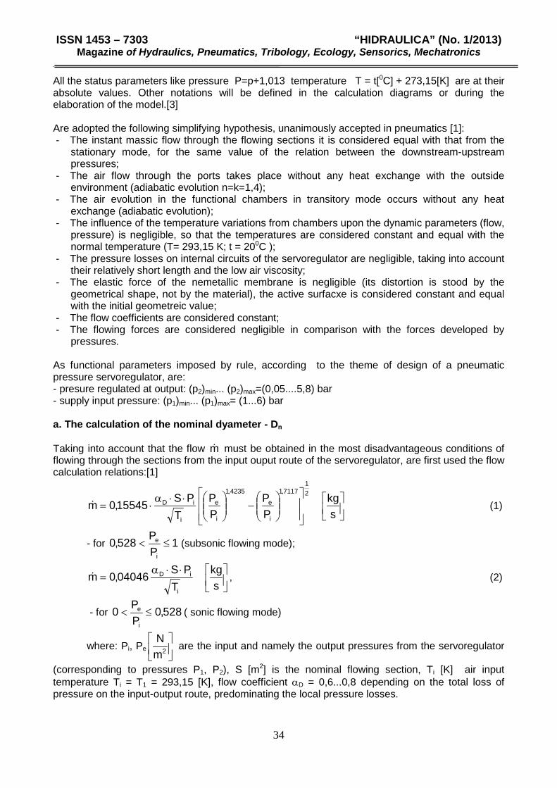
pressures. As functional parameters imposed by rule, according to the theme of design of a pneumatic pressure servoregulator, are: - presure regulated at output: (p2)min... (p2)max=(0,05....5,8) bar - supply input pressure: (p1)min... (p1)max= (1...6) bar a. The calculation of the nominal dyameter - Dn Taking into account that the flow m must be obtained in the most disadvantageous conditions of flowing through the sections from the input ouput route of the servoregulator, are first used the flow calculation relations:[1]
−
⋅⋅α⋅=
skg
PP
PP
TPS15545,0m
21
7117,1
i
e
4235,1
i
e
i
iD (1)
- for 1PP528,0
i
e ≤< (subsonic flowing mode);
⋅⋅α=
skg
TPS04046,0m
i
iD , (2)
- for 528,0PP0
i
e ≤< ( sonic flowing mode)
where: Pi, Pe
2m
N are the input and namely the output pressures from the servoregulator
(corresponding to pressures P1, P2), S [m2] is the nominal flowing section, Ti [K] air input temperature Ti = T1 = 293,15 [K], flow coefficient αD = 0,6...0,8 depending on the total loss of pressure on the input-output route, predominating the local pressure losses.
On this route there are two sudden variations of section, a decrease from the nominal section
4DS
2n
n⋅π
= at the flowing section dydS ⋅⋅= 3π and an increase from S to Sn. In the dame time
there are two changes in what regards the flowing direction with angles of 900 and three transformations of section shape (of jet). Since P1 [i T1 are the same, it means that only the
function
1
2
PPF from the paranthesis of the subsosnic flow relation (1) remains in discussion. Its
value decreases at the increase of the P2/P1 relationship value. The numeric coefficients of the relations from the subsonic flowing mode (1) and from the sonic flowing mode (2), even if different, the lowest flow it results to be that given by the relation (1). For the required massic flow: m , at
pressure pi in the most disadvantageous case of relation between pressures i
e
pp
, Ti=T1=293,15 K
and αD = 0,7, nominal section Sn [ ]2m must have the value:
7117,1
1
2
4235,1
1
21
1
15545,0
−
⋅⋅⋅
⋅=
PP
PPP
TmS
D
n
α
Knowing the nominal section it is calculated the nominal dyameter Dn:
ππ n
nn
nS
DD
S⋅
=⇒⋅
=4
4
2
b. The calculation of the maximum opening stroke – yd . the continuity of the flowing section ( fig. 2) imposes:[2]
dDn
D ydD⋅⋅⋅=
⋅⋅ 32
2
1 4παπα , or correspinding to the real flowing sections:
dn ydD ⋅⋅=⋅ 32 3,264,0 (3)
For the circular section as it is Sn, αD1= 0,815, and for the flowing section plane valve- seat S (the lateral surface of a cylinder) αD2= 0,732. Although the section from downstream of S is of a ring shape, is affected by the rod dyameter – d4, generally it is adopted d3= Dn. With the relation 3 it is calculated yd:
32
21
4 dD
yD
nDd ⋅⋅⋅
⋅⋅=
παπα
c. The dimensioning of the main valve (fig. 2). Being known the dyameter d3 it is calculated from the condition of resistence at the contact pressure of the non metallic sealing zone (from rubber) the dyameter d22. The most detrimental situation is when the valve seals the seat and p2=0. In relation with the distribution of pressure p1 on the valve, the dimensioning relation becomes:
1ac
ac322 pp
pdd−
⋅= (4)
Because it was ignored the force Farc of the spring, in reality reduced in relation with the force developed by pressure p1 it will be taken the admisible contact pressure: pac = (15...18).105 N/m2.
Due to constructive considerations, for placing the rubber ring in the valve (by means of vulcanization, pasting or crimping) the dyameter d2 it is dimensioned at the size: d2 = d22 + (3...4) mm. The calculation of the dyameter d1 it is made taking into account the balance of forces on the valve. For diminishing the forces developed by the different pressures p1 and p2 the valve is balanced (pressure p2 is brought under the valve too), solution which imposes the sealing of this chamber with a seal ring.For a more accurate evaluation of these forces it was stated the hypothesis that the transition from pressure p1 to p2 it is not step but ramp type, with the geometrical limits defined by the dyameters of the valve seat d22, namely d3 [3]
Knowing the numerical values of the dyameters d22, d4,d2,d3, it results the following dimensioning formula:
212121 4650)( ppppd ⋅−⋅=−⋅ (5)
Generalized for any ∆p=pi-pe,the relation (5) becomes :
pppppp
∆−=∆=−
12
21
ppppppd ∆⋅+⋅=∆−⋅−⋅=∆ 464)(4650 111
21 , meaning
pppd ∆⋅+⋅=∆ 464 121 (6)
The friction force from the seal, input by this ring will have the value:
(7) )( 211 ppbdFe −⋅⋅⋅⋅= πµ d. The force developed by pressure on valve and the friction force from the seal Considering the sense of force Fs developed by the pressures that charge it (in bars), with preset geometric elements (în cm), force Fs (în daN) has the expression:
( ) ( ) ( ) ( )
4444242
122
1221
24
232
23
222
12222
221 dpddpddpddppddpFs
πππππ⋅−−⋅−−⋅+−⋅
++−⋅= (8)
e. The dimensioning of the valve rod. The dyameter of the rod d4 is chosen constructively. For having a domain of the regulated output pressures close to the drive pressure values, the rod dyameter should be smaller. f. The calculation of the force on the membrane of the pneumatic pressure servoregulator In fig. 3 is shown the distribution of pressures on the elastic membrane of the servoregulator. Upon the assembly membrane rod act two forces developed by pressure: on the upper part of the membrane the drive pressure p3 and on the lower part the output pressure (regulated) p2.
As a result the force generated on the membrane is :
Fm = ( )2
24
25
3
25
44pddpd
⋅−⋅
−⋅⋅ ππ
4. The study of the piloting-command level and the equations of the model The force developed by the piezoelectric lamella, used as electro mechanic convertor was calculated and checked experimentally. From the relation (9), it results the equation of connection displacement lamella x – drive tension Uc of shape:
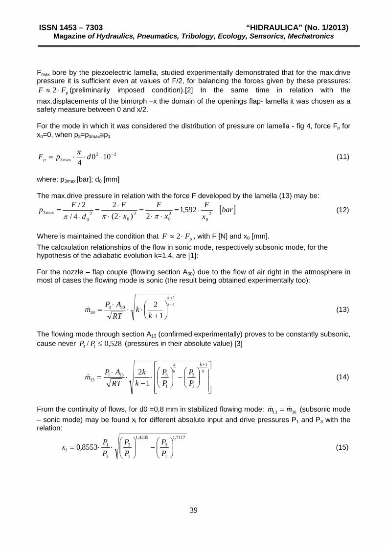
Fmax bore by the piezoelectric lamella, studied experimentally demonstrated that for the max.drive pressure it is sufficient even at values of F/2, for balancing the forces given by these pressures:
pFF ⋅≈ 2 (preliminarily imposed condition).[2] In the same time in relation with the max.displacements of the bimorph –x the domain of the openings flap- lamella it was chosen as a safety measure between 0 and x/2. For the mode in which it was considered the distribution of pressure on lamella - fig 4, force Fp for x0=0, when p3=p3max≅p1
22max3 100
4−⋅⋅⋅= dpFp
π (11)
where: p3max [bar]; d0 [mm] The max.drive pressure in relation with the force F developed by the lamella (13) may be:
[ ]barxF
xF
xF
dFp 592,1
2)2(2
4/2/
20
20
20
20
max3 ⋅=⋅⋅
=⋅⋅⋅
=⋅
=πππ
(12)
Where is maintained the condition that pFF ⋅≈ 2 , with F [N] and x0 [mm]. The calcxulation relationships of the flow in sonic mode, respectively subsonic mode, for the hypothesis of the adiabatic evolution k=1.4, are [1]: For the nozzle – flap couple (flowing section A30) due to the flow of air right in the atmosphere in most of cases the flowing mode is sonic (the result being obtained experimentally too):
11
30330 1
2 −+
+⋅⋅
⋅=
kk
kk
RTAPm (13)
The flowing mode through section A13 (confirmed experimentally) proves to be constantly subsonic, cause never 528,0/ 13 ≤PP (pressures in their absolute value) [3]
−
⋅
−⋅
⋅=
+k
kk
PP
PP
kk
RTAPm
1
1
3
2
1
313113 1
2 (14)
From the continuity of flows, for d0 =0,8 mm in stabilized flowing mode: 3013 mm = (subsonic mode – sonic mode) may be found xl for different absolute input and drive pressures P1 and P3 with the relation:
4. The mathematical model of the pneumatic pressure servoregulator For structuring the mathematical model of the pneumatic pressure servoregulator, it is used the schematic presentation from fig. 5 in which are configured the forces (previously determined) interferring in the operation of the servoregulator. The balance of forces at the level of the central mobile subassembly (valve - rod - membrane) has the following form: 0)y(sign)FF(FGFF iearcmaxms =⋅+−−++ (16) For eliminating pressure p3 from the equations of the mathematical model and their correlation with Uc – the drive-supply tension of the lamella:
5. Conclusions The pneumatic pressure servoregulator differs from a classic proportional regulator, at which the regulated pressures are installed due to a mechanic prompt, performed by hand. In its structure it was introduced a piloting step, operationally based on the pneumatic circuit nozzle-flap, which determine drive pressure p3 depending on the position of the flap –xl materialized by a piezoelectric actuator with bimorph lamella. The study of this circuit, in relation with the real flow modes of the air through its two sections of reference (A13 [i A30) allowed the determination of function p3 = p3(xl), which by means of the force of distortion of the lamella: x = x(Uc) and its constructive connection : xl=x0-x, was brought to the form p3=p3(Uc). The study of the piloting step,has shown that after certain openings xl the drive pressure - p3 does not decrease below certain values. In this situation for tensions Uc< 30 V have no regulation effect in the field Uc = (30...60) V are obtained desired regulated pressure values. The mathematical model set and its numerical simulation proves the theoretical possibility of achieving a pneumatic pressure servoregulator with proportional regulation characteristic. On the servoregulator obtained after design, the mathematical model allowed with an error caused by approximations, the achievement in theory of a proportional characteristic of regulation, whose validity will be subsequently studied on a physical model realized at the dimensions obtained in the stage of design of the pneumatic piezoelectric pressure servoregulator. REFERENCES [1[ Radcenco, Vs., Alexandrescu, N. – Calculation and design of the pneumatic elements and diagrams of automation, Technical Publishing house Bucuresti 1985 [2] Belforte, G., Gastaldi, L., Sorli, M. – Gli azionamenti piezoelettrici nel comando di valvole pneumatiche – O+P, septembre1998 [3] Matache, G – The study and improvement of the equipement regulating pressure in the pneumatic systems – Ph.D thesis