2060 S. 1/12 www.burkert.com Pneumatically operated 2/2-way angle seat valve with stainless steel actuator The pneumatically operated angle seat valve with stainless steel actuators fulfils the demands of tough process environments. Unrivalled cycle life and sealing integrity is guaranteed by the trusted self-adjusting spindle packing with V-seals. The stainless steel actuator is designed to withstand tough conditions. Laser welding allows a design without seals and smooth sur- faces that is both cleanable and robust. With a ducted exhaust air port the actuator can be isolated from the environment an optimum from a lifetime and hygienic point of view. High flow rates are attained with the optimized cast stainless steel 2 way body. Placed within the Bürkert process valves various port con- nections and a large accessory program are available. All wetted parts comply with the EC-Regulation 1935/2004, variants with FDA conformity are available on request, also explosion proof variants are available. Type 2060 Welded can be combined with... • Flow optimized stainless steel bodies with various port connections • Trusted inner parts for long cycle life • Actuator in stainless steel for demanding environments • Large accessory program with stroke limitation and feedback Content Valve specifications System spec. On/Off ELEMENT Request for quotation Type 2060 Type 8801-YE Type 8801-YE Technical data & ordering info. p. 1-4 Technical data & ordering info. p. 9 p. 11 Type 8697 feedback Stroke limiter Technical data Orifice DN15 to DN65; 1/2" to 2 1/2" Port connections Welded acc. to Clamp and threaded DIN EN ISO 1127/ISO 4200/DIN 11866 series B DIN 11850 series 2/DIN 11866 series A/DIN EN 10357 series A ASME BPE / DIN 11866 series C on request: SMS 3008 and BS485 on request Body material Stainless steel 316L Nominal pressure PN25 (Body) Actuator material 1.4404 (316L), 1.4308 Sealing material PTFE (others on request) Medium Water, alcohol, oils, fuels, hydraulic fluids, salt solution, alkali solutions, organic solvents, steam Viscosity max. 600 mm^2/s Spindle packing PTFE V-rings with spring compensation Medium temperature -10°C to 185°C Ambient temperature 0°C to 100°C at 150°C ambient temparature 0°C to 80°C at 150°C < ambient temparature ≤ 185°C Control medium Neutral gases, air Max. pilot pressure 10.5 bar 7.5 bar for actuator size 130mm (P) Pilot air ports thread G1/8 Installation As required, preferably with actuator in upright position Surface Finish Int. Ra ≤ 3,2μm (others on request) Type 8640/8644 valve island Type 6012/6014 P pilot valve
Transcript
2060
S. 1/12www.burkert.com
Pneumatically operated 2/2-way angle seat valve with stainless steel actuator
The pneumatically operated angle seat
valve with stainless steel actuators fulfi ls the
demands of tough process environments.
Unrivalled cycle life and sealing integrity is
guaranteed by the trusted self-adjusting
spindle packing with V-seals.
The stainless steel actuator is designed to
withstand tough conditions. Laser welding
allows a design without seals and smooth sur-
faces that is both cleanable and robust. With
a ducted exhaust air port the actuator can be
isolated from the environment an optimum
from a lifetime and hygienic point of view.
High fl ow rates are attained with the optimized
cast stainless steel 2 way body. Placed within
the Bürkert process valves various port con-
nections and a large accessory program are
available.
All wetted parts comply with the EC-Regulation
1935/2004, variants with FDA conformity are
available on request, also explosion proof
variants are available.
Type 2060 Welded can be combined with...
• Flow optimized stainless steel bodies with various port connections
• Trusted inner parts for long cycle life
• Actuator in stainless steel for demanding environments
• Large accessory program with stroke limitation and feedback
Content
Valve specifi cations System spec. On/Off ELEMENT Request for quotation
Type 2060 Type 8801-YE Type 8801-YE
Technical data & ordering info. p. 1-4 Technical data & ordering info. p. 9 p. 11
Type 8697
feedback
Stroke limiter
Technical data
Orifi ce DN15 to DN65; 1/2" to 2 1/2"
Port connections
Welded acc. to
Clamp and threaded
DIN EN ISO 1127/ISO 4200/DIN 11866 series B
DIN 11850 series 2/DIN 11866 series A/DIN EN 10357
series A ASME BPE / DIN 11866 series C
on request: SMS 3008 and BS485
on request
Body material Stainless steel 316L
Nominal pressure PN25 (Body)
Actuator material 1.4404 (316L), 1.4308
Sealing material PTFE (others on request)
Medium Water, alcohol, oils, fuels, hydraulic fl uids, salt solution,
alkali solutions, organic solvents, steam
Viscosity max. 600 mm^2/s
Spindle packing PTFE V-rings with spring compensation
Medium temperature -10°C to 185°C
Ambient temperature 0°C to 100°C at 150°C ambient temparature
0°C to 80°C at 150°C < ambient temparature ≤ 185°C
Control medium Neutral gases, air
Max. pilot pressure 10.5 bar
7.5 bar for actuator size 130mm (P)
Pilot air ports thread G1/8
Installation As required, preferably with actuator in upright position
Surface Finish Int. Ra ≤ 3,2μm (others on request)
Type 8640/8644
valve island
Type 6012/6014 P
pilot valve
2060
S. 2/12
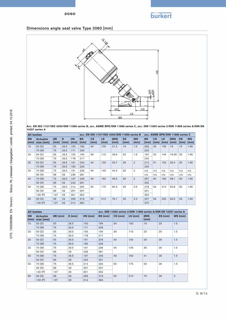
Technical data angle seat valve Type 2060 flow direction below the seat (for gases and liquids)
→
Control function A
→
Control function B
Normally closed by spring action Normally open by spring action
Pressure charts with control function B and fl ow direction below the seat
Actuator size 50 mm Actuator size 70 mm
16141210
86420
0 1 2 3 4 5 6 7 8 9 10
DN
15
DN
20
DN
25
Op
era
tin
g p
ress
ure
[b
ar]
Pilot pressure [bar]
16141210
86420
0 1 2 3 4 5 6 7 8 9 10
DN
15D
N20
DN
25
DN
32
DN
40
DN
50
11
Op
era
tin
g p
ress
ure
[b
ar]
Pilot pressure [bar]
Actuator size 90 mm Actuator size 130 mm
16141210
86420
0 1 2 3 4 5 6 7 8 9 10 11
DN
32D
N40
DN
50
DN
65
Op
era
tin
g p
ress
ure
[b
ar]
Pilot pressure [bar]
16141210
86420
0 1 2 3 4 5 6 7 8 9 10
DN
40D
N50
DN
65
Op
era
tin
g p
ress
ure
[b
ar]
Pilot pressure [bar]
Orifi ce Actuator size [mm]
Kv value water [m³/h]
Minimum pilot pressure CFA [bar]
Operating pressure up to +185ºC
[mm] [inch] CFA [bar] CFB [bar]
15 1/2“ 50 (D) 4.2 4.0 16 16
20 3/4“ 50 (D) 8 4.0 16 16
70 (M) 11 5.0 16 16
25 1“ 50 (D) 14 4.0 9 16
70 (M) 18 5.0 16 16
32 1 1/4“ 70 (M) 27 5.0 8.5 16
90 (N) 28 5.0 16 16
40 1 1/2“ 70 (M) 38 5.0 6 16
90 (N) 40 5.0 16 16
50 2“ 90 (N) 55 5.0 10 16
130 (P) 62 5.0 16 16
65 2 1/2“ 90 (N) 85 5.0 5 12
130 (P) 95 5.6 12 12
Flow rate: Kv value water [m3/h]: Measured at +20°C, 1 bar pressure at valve inlet and free outlet.
Pressure valves [bar]: Overpressure to the atmospheric pressure
2060
S. 3/12
Weld end body, flow direction below the seat, others on requestC
on
tro
l fu
ncti
on
Orifi ce
Po
rt c
on
ne
c-
tio
n t
ub
e Ø
x
wa
ll t
hik
ne
ss
[mm
]
Actu
ato
r siz
e
[mm
]
Pil
ot
pre
ssu
re
[ba
r]
Op
era
tin
g
pre
ssu
re u
pt
to +
185°C
[b
ar]
Ite
m n
o.
[mm
]
[in
ch
]
Acc. EN ISO 1127/ISO 4200/DIN 11866 series B
A
2/2-way valve,
externally controlled,
normally closed by
spring operation with
pilot valve (NC)
15 1/2“ 21.3 x 1.6 50 (D) 4.0 - 10.5 16 285 215
20 3/4“ 26.9 x 1.6 50 (D) 4.0 - 10.5 16 285 217
70 (M) 5.0 - 10.5 16 285 218
25 1“ 33.7 x 2.0 50 (D) 4.0 - 10.5 9 285 219
70 (M) 5.0 - 10.5 16 285 220
32 1 1/4“ 42.4 x 2.0 70 (M) 5.0 -10.5 8.5 285 221
90 (N) 5.0 -10.5 16 285 222
40 1 1/2“ 48.3 x 2.0 70 (M) 5.0 -10.5 6 285 223
90 (N) 5.0 -10.5 16 285 224
50 2“ 60.3 x 2.0 90 (N) 5.0 -10.5 10 285 515
130 (P) 5.0 - 7.5 16 285 705
65 2 1/2“ 76.1 x 2.3 90 (N) 5.0 -10.5 5 285 227
130 (P) 5.6 - 7.5 12 285 228
Acc. DIN 11850 series 2/DIN 11866 series A/DIN EN 10357 series A
15 1/2“ 19.0 x 1.5 50 (D) 4.0 - 10.5 16 285 201
20 3/4“ 23.0 x 1.5 50 (D) 4.0 - 10.5 16 285 203
70 (M) 5.0 - 10.5 16 285 204
25 1“ 29.0 x 1.5 50 (D) 4.0 - 10.5 9 285 205
70 (M) 5.0 - 10.5 16 285 206
32 1 1/4“ 35.0 x 1.5 70 (M) 5.0 -10.5 8.5 285 207
90 (N) 5.0 -10.5 16 285 208
40 1 1/2“ 41.0 x 1.5 70 (M) 5.0 -10.5 6 285 209
90 (N) 5.0 -10.5 16 285 210
50 2“ 53.0 x 1.5 90 (N) 5.0 -10.5 10 285 211
130 (P) 5.0 - 7.5 16 285 212
65 2 1/2“ 70.0 x 2.0 90 (N) 5.0 -10.5 5 285 213
130 (P) 5.6 - 7.5 12 285 214
Acc. ASME BPE/DIN 11866 series C
15 1/2“ 12.7 x 1.65 50 (D) 4.0 - 10.5 16 285 189
20 3/4“ 19.05 x 1.65 50 (D) 4.0 - 10.5 16 285 191
70 (M) 5.0 - 10.5 16 285 192
25 1“ 25.4 x 1.65 50 (D) 4.0 - 10.5 9 285 193
70 (M) 5.0 - 10.5 16 285 194
40 1 1/2“ 38.1 x 1.65 70 (M) 5.0 -10.5 6 285 195
90 (N) 5.0 -10.5 16 285 196
50 2“ 50.8 x 1.65 90 (N) 5.0 -10.5 10 285 197
130 (P) 5.0 - 7.5 16 285 198
65 2 1/2“ 63.5 x 1.65 90 (N) 5.0 -10.5 5 285 199
130 (P) 5.6 - 7.5 12 285 200
Ordering chart angle seat valve Type 2060, flow direction below the seat (for gases and liquids)
A
2/2-way valve,
externally controlled,
normally closed by
spring operation with
pilot valve (NC)
A
2/2-way valve,
externally controlled,
normally closed by
spring operation with
pilot valve (NC)
Control functionI (double-acting)
Port connection(threaded port / clamp)
2060
S. 4/12
Ordering chart angle seat valve Type 2060, flow direction below the seat (for gases and liquids)
Weld end body, flow direction below the seat, others on requestC
on
tro
l fu
ncti
on
Orifi ce
Po
rt c
on
ne
c-
tio
n t
ub
e Ø
x w
all
th
ik-
ne
ss [
mm
]
Actu
ato
r siz
e [
mm
]
Pil
ot
pre
ssu
-re
[b
ar]
Op
era
tin
g
pre
ssu
re u
pt
to +
185°C
[b
ar]
Ite
m n
o.
[mm
]
[in
ch
]
Acc. EN ISO 1127/ISO 4200/DIN 11866 series B
15 1/2“ 21.3 x 1.6 50 (D) see pressure
chart
16 285 500
70 (M) 16 287 565
20 3/4“ 26.9 x 1.6 50 (D) 16 285 501
70 (M) 16 287 566
25 1“ 33.7 x 2.0 70 (M) 16 285 503
32 1 1/4“ 42.4 x 2.0 70 (M) 16 285 504
40 1 1/2“ 48.3 x 2.0 70 (M) 16 285 505
50 2“ 60.3 x 2.0 70 (M) 16 287 567
65 2 1/2“ 76.1 x 2.3 90 (N) 12 285 511
Acc. DIN 11850 series 2/DIN 11866 series A/DIN EN 10357 series A
15 1/2“ 19.0 x 1.5 50 (D) see pressure
chart
16 287 555
70 (M) 16 287 556
20 3/4“ 23.0 x 1.5 50 (D) 16 287 557
70 (M) 16 287 558
25 1“ 29.0 x 1.5 70 (M) 16 287 559
32 1 1/4“ 35.0 x 1.5 70 (M) 16 287 560
40 1 1/2“ 41.0 x 1.5 70 (M) 16 287 561
50 2“ 53.0 x 1.5 90 (N) 16 287 562
65 2 1/2“ 70.0 x 2.0 90 (N) 12 287 563
Acc. ASME BPE/DIN 11866 series C
15 1/2“ 12.7 x 1.65 50 (D) see pressure
chart
16 285 499
70 (M) 16 287 548
20 3/4“ 19.05 x 1.65 50 (D) 16 287 549
70 (M) 16 287 550
25 1“ 25.4 x 1.65 70 (M) 16 287 551
40 1 1/2“ 38.1 x 1.65 70 (M) 16 287 552
50 2“ 50.8 x 1.65 70 (M) 16 285 509
65 2 1/2“ 63.5 x 1.65 90 (N) 12 287 553
B
2/2-way valve,
externally controlled,
normally opened by
spring, operation with
pilot valve (NO)
B
2/2-way valve,
externally controlled,
normally opened by
spring, operation with
pilot valve (NO)
B
2/2-way valve,
externally controlled,
normally opened by
spring, operation with
pilot valve (NO)
2060
S. 5/12
Technical data angle seat valve Type 2060 flow direction above the seat (for gases and liquids)
→Control function A Attention!
Valves with fl ow above the seat are only
conditionally usable for liquid medium.
There is a danger of waterhammer!
Normally closed by spring action
Pressure charts with control function A and fl ow direction above the seat
Actuator size 50 mm Actuator size 70 mm
16141210
86420
0 1 2 3 4 5 6 7 8 9 10
DN
15
DN
20
DN
25
Op
era
tin
g p
ress
ure
[b
ar]
Pilot pressure [bar]
16141210
86420
0 1 2 3 4 5 6 7 8 9 10
DN
32
DN
40
DN
50
Op
era
tin
g p
ress
ure
[b
ar]
Pilot pressure [bar]
Actuator size 90 mm
16141210
86420
0 1 2 3 4 5 6 7 8 9 10
DN
40
DN
50
Op
era
tin
g p
ress
ure
[b
ar]
Pilot pressure [bar]
Orifi ce Actuator size [mm]
Kv value water [m³/h]
Operating pressure up to +185ºC
[mm] [inch] CFA [bar]
15 1/2“ 50 (D) 4.2 16
20 3/4“ 50 (D) 8 16
25 1“ 50 (D) 14 16
32 1 1/4“ 70 (M) 28 16
40 1 1/2“ 70 (M) 38 16
50 2“ 70 (M) 50 12
90 (N) 55 15
Flow rate: Kv value water [m3/h]: Measured at +20°C, 1 bar pressure at valve inlet and free outlet.
Pressure valves [bar]: Overpressure to the atmospheric pressure
S. 6/12
2060
Ordering chart angle seat valve Type 2060, flow direction above the seat (for gases and liquids)
Weld end body, flow direction above the seat, others on request
Co
ntr
ol
fun
cti
on
Orifi ce
Po
rt c
on
ne
c-
tio
n t
ub
e Ø
x
wa
ll t
hik
ne
ss
[mm
]
Actu
ato
r siz
e
[mm
]
Pil
ot
pre
ssu
re
[ba
r]
Op
era
tin
g
pre
ssu
re u
pt
to +
185°C
[b
ar]
Ite
m n
o.
[mm
]
[in
ch
]
Acc. EN ISO 1127/ISO 4200/DIN 11866 series B
15 1/2“ 21.3 x 1.6 50 (D) see pressure
chart
16 287 541
20 3/4“ 26.9 x 1.6 50 (D) 16 287 542
25 1“ 33.7 x 2.0 50 (D) 16 287 543
32 1 1/4“ 42.4 x 2.0 70 (M) 16 287 544
40 1 1/2“ 48.3 x 2.0 70 (M) 16 287 545
50 2“ 60.3 x 2.0 70 (M) 12 287 546
90 (N) 16 287 547
Acc. DIN 11850 series 2/DIN 11866 series A/DIN EN 10357 series A
15 1/2“ 19.0 x 1.5 50 (D) see pressure
chart
16 287 534
20 3/4“ 23.0 x 1.5 50 (D) 16 287 535
25 1“ 29.0 x 1.5 50 (D) 16 287 536
32 1 1/4“ 35.0 x 1.5 70 (M) 16 287 537
40 1 1/2“ 41.0 x 1.5 70 (M) 16 287 538
50 2“ 53.0 x 1.5 70 (M) 12 287 539
90 (N) 16 287 540
Acc. ASME BPE/DIN 11866 series C
15 1/2“ 12.7 x 1.65 50 (D) see pressure
chart
16 287 528
20 3/4“ 19.05 x 1.65 50 (D) 16 287 529
25 1“ 25.4 x 1.65 50 (D) 16 287 530
40 1 1/2“ 38.1 x 1.65 70 (M) 16 287 531
50 2“ 50.8 x 1.65 70 (M) 12 287 532
90 (N) 16 287 533
A
2/2-way valve, externally
controlled, normally closed
by spring operation with pilot
valve (NC)
A
2/2-way valve, externally
controlled, normally closed
by spring operation with pilot
valve (NC)
A
2/2-way valve, externally
controlled, normally closed
by spring operation with pilot
valve (NC)
S. 7/12
2060
Materials angle seat valve Type 2060
1 Optical position indicator Transparent cap polysulfone PSU
2 Pilot air ports Threaded port G1/8“
Stainless steel 1.4404 (316L)
3 Spring seat Stainless steel 1.4308
4 Spindle extension Stainless steel 1.4104
5 Actuator cover Stainless steel 1.4404 (316L)
6 Piston seal FKM
7 Actuator base (interface) Stainless steel 1.4308